1
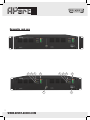
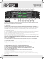
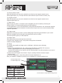
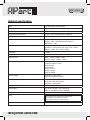
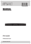
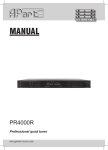
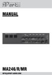
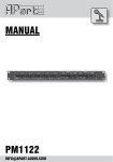
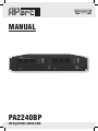
MANUAL
PA2240BP
[email protected]
Removable rack ears
5
4
2
3
5
6
WWW.APART-AUDIO.COM
4
2
3
1
Front panel
1. Power switch
To turn the power on and off.
2. Overload indicator CH1 & CH2
This red LED illuminates when one of the protections have been activated. No sound will be heard
anymore. This will be in case of overheating being the result of drawing too much power from your
amplifier or the impedance connected is below the minimum load impedance.
See also point 17 “bass control”.
3. Level indicators/clip-limit CH1 & CH2
The bottom LED will light green after powering on. To work under normal conditions the volume
indicator should be kept under 0dB. At +4dB a limiter will be activated. This red LED indicates that the
“auto gain circuit” reduces the level below clipping. This can be bypassed by qualified personnel only
(see jumper inside), but voids the guarantee and the LED will continue to flicker.
This is NOT a clip indicator!
When the overheating protection circuit is active, the level indicators will all go dark. If this occurs
regularly, check the total load impedance and make sure the airflow around the amplifier is
not obstructed.
4. Prior LED CH1 & CH2
This yellow LED will illuminate when the prior input has been selected by means of the priority input
contact (see 11b). In bridge mode only the indication of CH1 are valid.
5. Program LED CH1 & CH2
This green LED tells you that the ‘program’ input is active.
6. Bridged LED
This yellow LED tells you when the amplifier is in BRIDGE mode (= 480Watts)
Connect a sound source to the program or priority input 2 in bridge mode.
[email protected]
9
19
20
14 13
11a
11b
11c
12
15 16
17
18
10
19
REAR panel
14 13 11a 11b 11c 12 15 16 17 18
9. Earth lift switch
In case hum and buzz appears when a line source has been connected, lifting the audio ground can
be a solution. Correct wiring can avoid this problem.
10. Mains socket
The unit can be connected to the mains circuit by a standard IEC type power cord. This socket
contains a 8.0 AT, slow blow fuse. Use a screw driver to flip out the fuse compartment and to replace
it by the same type. When this fuse blows frequently you should check the speaker load or bring the
PA-2240BP to a qualified service centre. First check whether you didn’t use a quick-blow fuse!
11. Priority control connector
a. At these terminals (-/+) 24V DC will be available (max. 0,6A) from the moment the ‘priority switch’
has been activated, to activate priority relays of local volume attenuators or other devices.
In bridge mode only the channel 1 terminals can be used.
b. prior contact: when you shorten these contacts, the input of the priority line input will be activated.
At the same time 24 V DC will be presented to terminals 11a.
c. prior input: here you can feed the audio source for paging, emergency messages, etc.. The signal
should be at line level. Please use a balanced, shielded line cable. Connect the HOT signal to +, the
COLD to - and the shield to G.
No microphones should be connected directly to this input without using a mic to line preamplifier.
12. Program input connector
Here you can feed the audio source for music playback (background music)
The signal should be at line level. Please use a balanced, shielded line cable. Connect the
HOT signal to +, the COLD to - and the shield to G.
13. Speaker output connector. (2 channel operation mode)
For low impedance use COM and 4 Ω. Keep the impedance above 4 Ω.
For 35, 50, 70 or 100V speaker lines use COM and 35, 50, 70 or 100V terminals.
For 100V operation, the total minimum impedance of the loudspeaker line has to be 42Ω
70V = 21Ω / 50V = 10Ω / 35V = 5.1Ω .
Don’t mix the types of speaker connections. Only one at the time should be used.
14. Emergency power supply.
You can power the amplifier directly from a emergency battery or power supply with
24V DC/6.5A (each channel). Remember that output power capacity will be reduced on emergency
power supply.
WWW.APART-AUDIO.COM
15. Priority volume control
With this attenuator you can set the desired level of the line level signal inserted into the
priority signal input (11c). This input becomes active when the prior contact is closed (11b)
16. Program volume
With this attenuator you can set the desired level of the line level signal inserted into the
program signal input (12)
17. Bass control
Adjust as per your taste. In reverbant rooms intelligibility can be increased by decrasing the
amount of bass. The centre position gives you a flat response.
In 100V applications, it’s not recommended to really boost bass because it can overload the amplifier
or speakers to easily. We recommend to use this control only as low-cut or as well considered bass
response adjustment.
18. Treble control
Adjust the level as per your taste or needs. Adding high frequencies gives brillance to your sound.
High freq. feedback can be removed by decreasing the amount of treble.
The centre position gives you a flat response.
19. Airflow output
This airflow outputs should be kept free at all times !
To give the fan a longer life time, it only starts running when the heatsink
reaches a certain temperature.
20. Bridge
To configure the amplifier to bridge mode (= 480Watts / 100Volts) use the following
connections.
1) Connect the loudspeaker line, the + (hot) pole to the channel 1 amplifier 50V connector
and the -(negative) pole to the channel 2 amplifier 50V connector.
Use the 35V connectors if you want to use the 70Volts setting or the 4Ω connections if you want to
connect an 8Ω speaker.
2) Connect the audio signal to the channel 1 inputs. (in bridge mode the channel 2 inputs
are not in use).
3) Push the bridge button, verify if the yellow led on the frontpanel is on.
Now your amplifier is capable of producing up to 480Watts into 100Volts speaker lines.
Push the bridge button
to enable bridge mode.
Bridge mode
output
Min. impedance
100Volts
21 Ω
70Volts
10.5 Ω
4Ω
8Ω
Use the channel 1 audio inputs for bridge mode.
[email protected]
Controls inside
Inside settings should only be done by persons familiar to electrical equipment!
A. Limiter active jumper
Your PA-2240BP has been shipped with the limiters enabled for both channels.
The jumpers are located on the inner PCB’s on the rear side.
Channel 1 = jumper JP101 / Channel 2 = jumper JP201
Caution : removing the jumpers voids warranty.
B. Power supply fuses (inside the housing)
When one of these fuses blows, replace them by the same type.
Fuses marked F403 and F404 : 20A quick blow
Fuses marked F405 and F406 : 3.15A slow blow
The fuses are located inside on the power supply pcb.
When this happens frequently, contact your nearest dealer.
19” Rack mounting
The BP2240BP can be rackmounted. In this case, remove the 3 screws from the left and right side
and mount the rack-ears with the supplied screws. Remember to provide adequate support at the rear
of the amplifier, special mounting holes are provided at the rear.
Warning: never obstruct the free airflow around the amplifier’s front, side and rear.
Maintenace
The amplifier is free of maintenace however regular cleaning of the air vents with compressed air is
adviseable to ensure long term reliability.
The cooling fan is a mechanical device and its function should be checked regularly.
If replacement becomes necessary, contact your local dealer.
WWW.APART-AUDIO.COM
Technical specifications
Type
2 x 240 watts power amplifier
Output power capacity
2 x 240 watts rms or 1 x 480 watts rms
Frequency response
35Hz - 22KHz (low cut inside at 50Hz)
Total harmonic distortion
<0.5% (1KHz nominal power capacity)
Signal to noise ratio
>95dB
Inputs
Program : 0dB - 10K / Balanced Euroblock
Priority : 0dB - 10K / Balanced Euroblock
Sensitivity : -1dB
Speaker outputs
channel 1 : 4 ohm, 35V, 50V, 70V, 100V / 240W
channel 2 : 4 ohm, 35V, 50V, 70V, 100V / 240W
Bridge : 8 ohm, 70V , 100V / 480W
Crosstalk
>75dB
Additional outputs
2 X 24V Piority output , MAX 0.6A
Tone control
Bass : 100Hz +10dB / -14dB
Treble : 10KHz +10dB / -14dB
Controls rear panel
Priority volume control
Program volume control
treble control
bass control
priority control
bridge - stereo
earth lift switch
Power supply
230V AC (+/-5%) 50Hz
24V DC emergency supply
Power consumption
230V AC /1050VA MAX
230V AC / 500 VA Program
24V DC / 13A Program
Fuse
8.0T (rear panel)
Dimensions
D X W X H in MM : 412 X 430 X 90
With 19” brackets monted : 483MM
Weight
Net weight: 21.70Kg / Shipping weight : 24.10Kg
Note
Above specs. are measured for lab purpose.
As standard use, limiters are active
and might influence the values above.
[email protected]
ANY SUGGESTION?
They are well appreciated and eventually rewarded!
Send your ideas or suggestions to
[email protected]
PA2240BP is developed by
Audioprof nv
Lanteernhofstraat 90
BE-2100 Deurne
BELGIUM
WWW.APART-AUDIO.COM