1
PJL6223/PJL6233
LCD Projector
User Guide
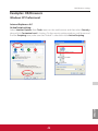
IMPORTANT: Please read this User Guide to obtain important information on installing
and using your product in a safe manner, as well as registering your product for future
service. Warranty information contained in this User Guide will describe your limited
coverage from ViewSonic Corporation, which is also found on our web site at http://www.
YLHZVRQLFFRPLQ(QJOLVKRULQVSHFL¿FODQJXDJHVXVLQJWKH5HJLRQDOVHOHFWLRQER[LQ
the upper right corner of our website. “Antes de operar su equipo lea cu idadosamente
las instrucciones en este manual”
Compliance Information
FCC Statement
This device complies with part 15 of FCC Rules. Operation is subject to the following two conditions: (1) this device
may not cause harmful interference, and (2) this device must accept any interference received, including interference
that may cause undesired operation.
This equipment has been tested and found to comply with the limits for a Class B digital device, pursuant to part 15 of
the FCC Rules. These limits are designed to provide reasonable protection against harmful interference in a residential
installation. This equipment generates, uses, and can radiate radio frequency energy, and if not installed and used
in accordance with the instructions, may cause harmful interference to radio communications. However, there is no
guarantee that interference will not occur in a particular installation. If this equipment does cause harmful interference
to radio or television reception, which can be determined by turning the equipment off and on, the user is encouraged
to try to correct the interference by one or more of the following measures:
5HRULHQWRUUHORFDWHWKHUHFHLYLQJDQWHQQD
,QFUHDVHWKHVHSDUDWLRQEHWZHHQWKHHTXLSPHQWDQGUHFHLYHU
&RQQHFWWKHHTXLSPHQWLQWRDQRXWOHWRQDFLUFXLWGLIIHUHQWIURPWKDWWRZKLFKWKHUHFHLYHULVFRQQHFWHG
&RQVXOWWKHGHDOHURUDQH[SHULHQFHGUDGLR79WHFKQLFLDQIRUKHOS
Warning: <RXDUHFDXWLRQHGWKDWFKDQJHVRUPRGL¿FDWLRQVQRWH[SUHVVO\DSSURYHGE\WKHSDUW\UHVSRQVLEOHIRU
compliance could void your authority to operate the equipment.
For Canada
7KLV&ODVV%GLJLWDODSSDUDWXVFRPSOLHVZLWK&DQDGLDQ,&(6
&HWDSSDUHLOQXPpULTXHGHODFODVVH%HVWFRQIRUPHjODQRUPH10%GX&DQDGD
CE Conformity for European Countries
7KHGHYLFHFRPSOLHVZLWKWKH(0&'LUHFWLYH(&DQG/RZ9ROWDJH'LUHFWLYH(&
Following information is only for EU-member states:
7KHPDUNLVLQFRPSOLDQFHZLWKWKH:DVWH(OHFWULFDODQG(OHFWURQLF(TXLSPHQW'LUHFWLYH(&:(((
The mark indicates the requirement NOT to dispose the equipment including any spent or discarded batteries
or accumulators as unsorted municipal waste, but use the return and collection systems available.
If the batteries, accumulators and button cells included with this equipment, display the chemical symbol Hg,
&GRU3EWKHQLWPHDQVWKDWWKHEDWWHU\KDVDKHDY\PHWDOFRQWHQWRIPRUHWKDQ0HUFXU\RUPRUH
WKDQ&DGPLXPRUPRUHWKDQ/HDG
ViewSonic
i
i
PJL6223/PJL6233
Important Safety Instructions
1.
2.
5.
7.
Read these instructions.
Keep these instructions.
+HHGDOOZDUQLQJV
)ROORZDOOLQVWUXFWLRQV
Do not use this unit near water.
&OHDQZLWKDVRIWGU\FORWK
Do not block any ventilation openings. Install the unit in accordance with the manufacturer’s instructions.
'RQRWLQVWDOOQHDUDQ\KHDWVRXUFHVVXFKDVUDGLDWRUVKHDWUHJLVWHUVVWRYHVRURWKHUGHYLFHVLQFOXGLQJ
DPSOL¿HUVWKDWSURGXFHKHDW
'RQRWGHIHDWWKHVDIHW\SXUSRVHRIWKHSRODUL]HGRUJURXQGLQJW\SHSOXJ$SRODUL]HGSOXJKDVWZREODGHVZLWKRQH
wider than the other. A grounding type plug has two blades and a third grounding prong. The wide blade and the
WKLUGSURQJDUHSURYLGHGIRU\RXUVDIHW\,IWKHSURYLGHGSOXJGRHVQRW¿WLQWR\RXURXWOHWFRQVXOWDQHOHFWULFLDQIRU
replacement of the obsolete outlet.
3URWHFWWKHSRZHUFRUGIURPEHLQJZDONHGRQRUSLQFKHGSDUWLFXODUO\DWSOXJV&RQYHQLHQFHUHFHSWDFOHVDQG
WKHSRLQWZKHUHWKH\H[LWIURPWKHXQLW%HVXUHWKDWWKHSRZHURXWOHWLVORFDWHGQHDUWKHXQLWVRWKDWLWLVHDVLO\
accessible.
2QO\XVHDWWDFKPHQWVDFFHVVRULHVVSHFL¿HGE\WKHPDQXIDFWXUHU
8
VHRQO\ZLWKWKHFDUWVWDQGWULSRGEUDFNHWRUWDEOHVSHFL¿HGE\WKHPDQXIDFWXUHURUVROGZLWKWKHXQLW
When a cart is used, use caution when moving the cart/unit combination to avoid injury from tipping over.
8
QSOXJWKLVXQLWZKHQXQXVHGIRUORQJSHULRGVRIWLPH
5
HIHUDOOVHUYLFLQJWRTXDOL¿HGVHUYLFHSHUVRQQHO6HUYLFLQJLVUHTXLUHGZKHQWKHXQLWKDVEHHQGDPDJHGLQDQ\
ZD\VXFKDVLIWKHSRZHUVXSSO\FRUGRUSOXJLVGDPDJHGLIOLTXLGLVVSLOOHGRQWRRUREMHFWVIDOOLQWRWKHXQLWLIWKH
XQLWLVH[SRVHGWRUDLQRUPRLVWXUHRULIWKHXQLWGRHVQRWRSHUDWHQRUPDOO\RUKDVEHHQGURSSHG
ViewSonic
ii
ii
PJL6223/PJL6233
Declaration of RoHS Compliance
7KLVSURGXFWKDVEHHQGHVLJQHGDQGPDQXIDFWXUHGLQFRPSOLDQFHZLWK'LUHFWLYH(&RIWKH(XURSHDQ
3DUOLDPHQWDQGWKH&RXQFLORQUHVWULFWLRQRIWKHXVHRIFHUWDLQKD]DUGRXVVXEVWDQFHVLQHOHFWULFDODQGHOHFWURQLF
HTXLSPHQW5R+6'LUHFWLYHDQGLVGHHPHGWRFRPSO\ZLWKWKHPD[LPXPFRQFHQWUDWLRQYDOXHVLVVXHGE\WKH(XURSHDQ
Technical Adaptation Committee (TAC) as shown below:
Substance
Proposed Maximum Concentration
Actual Concentration
/HDG3E
Mercury (Hg)
Cadmium (Cd)
+H[DYDOHQW&KURPLXP&U)
Polybrominated biphenyls (PBB)
Polybrominated diphenyl ethers (PBDE)
&HUWDLQFRPSRQHQWVRISURGXFWVDVVWDWHGDERYHDUHH[HPSWHGXQGHUWKH$QQH[RIWKH5R+6'LUHFWLYHVDVQRWHG
below:
([DPSOHVRIH[HPSWHGFRPSRQHQWVDUH
0HUFXU\LQFRPSDFWÀXRUHVFHQWODPSVQRWH[FHHGLQJPJSHUODPSDQGLQRWKHUODPSVQRWVSHFL¿FDOO\PHQWLRQHGLQ
WKH$QQH[RI5R+6'LUHFWLYH
/HDGLQJODVVRIFDWKRGHUD\WXEHVHOHFWURQLFFRPSRQHQWVÀXRUHVFHQWWXEHVDQGHOHFWURQLFFHUDPLFSDUWVHJ
SLH]RHOHFWURQLFGHYLFHV
/HDGLQKLJKWHPSHUDWXUHW\SHVROGHUVLHOHDGEDVHGDOOR\VFRQWDLQLQJE\ZHLJKWRUPRUHOHDG
/HDGDVDQDOORWWLQJHOHPHQWLQVWHHOFRQWDLQLQJXSWROHDGE\ZHLJKWDOXPLQLXPFRQWDLQLQJXSWROHDGE\
ZHLJKWDQGDVDFRRSHUDOOR\FRQWDLQLQJXSWROHDGE\ZHLJKW
ViewSonic
iii
iii
PJL6223/PJL6233
Copyright Information
Copyright © ViewSonic®&RUSRUDWLRQ$OOULJKWVUHVHUYHG
Macintosh and Power Macintosh are registered trademarks of Apple Inc.
Microsoft, Windows, Windows NT, and the Windows logo are registered trademarks of Microsoft Corporation in the
United States and other countries.
ViewSonic, the three birds logo, OnView, ViewMatch, and ViewMeter are registered trademarks of ViewSonic
Corporation.
VESA is a registered trademark of the Video Electronics Standards Association. DPMS and DDC are trademarks of
VESA.
PS/2, VGA and XGA are registered trademarks of International Business Machines Corporation.
Disclaimer: ViewSonic Corporation shall not be liable for technical or editorial errors or omissions contained herein;
nor for incidental or consequential damages resulting from furnishing this material, or the performance or use of this
product.
In the interest of continuing product improvement, ViewSonic Corporation reserves the right to change product
VSHFL¿FDWLRQVZLWKRXWQRWLFH,QIRUPDWLRQLQWKLVGRFXPHQWPD\FKDQJHZLWKRXWQRWLFH
No part of this document may be copied, reproduced, or transmitted by any means, for any purpose without prior
written permission from ViewSonic Corporation.
Product Registration
To meet your future needs, and to receive any additional product information as it becomes available, please register your
product on the Internet at: www.viewsonic.com. The ViewSonic®:L]DUG&'520DOVRSURYLGHVDQRSSRUWXQLW\IRU\RXWR
SULQWWKHUHJLVWUDWLRQIRUPZKLFK\RXPD\PDLORUID[WR9LHZ6RQLF
For Your Records
Product Name:
Model Number:
Document Number:
Serial Number:
Purchase Date:
3-/3-/
9LHZ6RQLF/&'3URMHFWRU
963-/963-/
3-/B3-/B8*B(1*5HY$
BBBBBBBBBBBBBBBBBBBBBBBBBBBBBBBBBBBBBBBB
BBBBBBBBBBBBBBBBBBBBBBBBBBBBBBBBBBBBBBBB
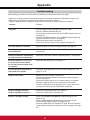
Product disposal at end of product life
The lamp in this product contains mercury which can be dangerous to you and the environment. Please use care and
dispose of in accordance with local, state or federal laws.
ViewSonic respects the environment and is committed to working and living green. Thank you for being part of Smarter,
Greener Computing. Please visit ViewSonic website to learn more.
86$&DQDGDKWWSZZZYLHZVRQLFFRPFRPSDQ\JUHHQUHF\FOHSURJUDP
(XURSHKWWSZZZYLHZVRQLFHXURSHFRPXNVXSSRUWUHF\FOLQJLQIRUPDWLRQ
7DLZDQKWWSUHF\FOHHSDJRYWZUHF\FOHLQGH[DVS[
ViewSonic
iv
iv
PJL6223/PJL6233
User Guide
Network Set-up and Operation
PJ Network Manager for Windows
User Guide
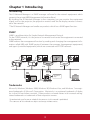
Features and Design
This Multimedia Projector is designed with the most advanced technology for portability, durability, and ease of use.
7KLVSURMHFWRUXWLOL]HVEXLOWLQPXOWLPHGLDIHDWXUHVDSDOHWWHRIPLOOLRQFRORUVDQGPDWUL[OLTXLGFU\VWDOGLVSOD\
/&'WHFKQRORJ\
Ƈ
Compact Design
Ƈ
7KLVSURMHFWRULVGHVLJQHGFRPSDFWLQVL]HDQGZHLJKW
It is easy to carry and installed anywhere you wish to
use.
Ƈ
Simple Computer System Setting
7KHSURMHFWRUKDVWKH0XOWLVFDQV\VWHPWRFRQIRUPWR
Ƈ Helpful Maintenance Functions
DOPRVWDOOFRPSXWHURXWSXWVLJQDOVTXLFNO\S8SWR
/DPSDQGILOWHUPDLQWHQDQFHIXQFWLRQVSURYLGHIRU
WUXGA resolution can be accepted.
better and proper maintenance of the projector.
Ƈ
Useful Functions for Presentations
7KH GLJLWDO ]RRP IXQFWLRQ DOORZV \RX WR IRFXV RQ WKH
FUXFLDOLQIRUPDWLRQGXULQJDSUHVHQWDWLRQS
%ODFNERDUGV FDQ EH XVHG DV D SURMHFWLRQ VFUHHQ
7KHERDUGFRORULVOLPLWHGWR*UHHQSS
Ƈ
Lamp Control
The Security function helps you to ensure security
of the projector. With the Key lock function, you can
lock the operation on the top control or remote control
S 3,1 FRGH ORFN IXQFWLRQ SUHYHQWV XQDXWKRUL]HG
XVHRIWKHSURMHFWRUSS±
Ƈ
Ƈ
Direct Off Function
Ƈ
With the Direct Off function, you can disconnect the
power cord from the wall outlet or turn off the breaker
HYHQGXULQJSURMHFWLRQS
7KLV SURMHFWRU LV ORDGHG ZLWK WKH :LUHG /$1 QHWZRUN
function. You can operate and manage the projector
via network. For details, refer to the User Guide of
³1HWZRUN6HWXSDQG2SHUDWLRQ´
Auto Setup Function
Colorboard Function
At the time of simple projection on the colored wall,
you can get the close color image to the color image
projected on a white screen by selecting the similar
color to the wall color from the preset four colors.
Ƈ
Logo Function
7KH/RJRIXQFWLRQDOORZV\RXWRFXVWRPL]HWKHVFUHHQ
ORJR SS <RX FDQ FDSWXUH DQ LPDJH IRU WKH
VFUHHQ ORJR DQG XVH LW IRU WKH VWDUWLQJXS GLVSOD\ RU
between presentations.
Ƈ
Multilanguage Menu Display
Ƈ
Ƈ
LAN Network Function
This function enables Input search, Auto Keystone
correction and Auto PC adjustment by simple pressing
WKH$8726(783EXWWRQRQWKHWRSFRQWUROS
Brightness of the projection lamp can be selected
SS
Ƈ
Security Function
Switchable Interface Terminal
The projector provides a switchable interface terminal.
You can use the terminal as computer input or monitor
RXWSXWFRQYHQLHQWO\S
Power Management
The Power management function reduces power
FRQVXPSWLRQDQGPDLQWDLQVWKHODPSOLIHS
2SHUDWLRQPHQXLVDYDLODEOHLQODQJXDJHV(QJOLVK
German, French, Italian, Spanish, Portuguese, Dutch,
Swedish, Finnish, Polish, Hungarian, Romanian,
5XVVLDQ7XUNLVK.D]DNK9LHWQDPHVH&KLQHVH
.RUHDQ-DSDQHVHDQG7KDLS
Ƈ
Closed Caption
This is a printed version of the program sound or other
information displayed on the screen. You can turn on
the feature and switch the channels. (p.52)
3Note:
7KH2Q6FUHHQ0HQXDQGILJXUHVLQWKLVPDQXDOPD\GLIIHUVOLJKWO\IURPWKHSURGXFW
7KHFRQWHQWVRIWKLVPDQXDODUHVXEMHFWWRFKDQJHZLWKRXWQRWLFH
2
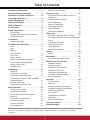
Table of Contents
Remote Control Operation
Compliance Information . . . . . . . . . . . . . . . . i
Important Safety Instructions . . . . . . . . . . . .ii
Declaration of RoHS Compliance . . . . . . . . iii
Copyright Information . . . . . . . . . . . . . . . . . iv
Product Registration . . . . . . . . . . . . . . . . . . iv
Features and Design . . . . . . . . . . . . . . . . . . .2
Table of Contents . . . . . . . . . . . . . . . . . . . . . .3
To the Owner. . . . . . . . . . . . . . . . . . . . . . . . . .4
Safety Instructions . . . . . . . . . . . . . . . . . . . . .5
$LU&LUFXODWLRQ
,QVWDOOLQJWKH3URMHFWRULQ3URSHU3RVLWLRQ
0RYLQJWKH3URMHFWRU
Computer Input . . . . . . . . . . . . . . . . . . . . . .27
Input Source Selection (RGB: Computer 1/
Computer 2)
&RPSXWHU6\VWHP6HOHFWLRQ
$XWR3&$GMXVWPHQW
0DQXDO3&$GMXVWPHQW
,PDJH0RGH6HOHFWLRQ
,PDJH$GMXVWPHQW
6FUHHQ6L]H$GMXVWPHQW
,QSXW6RXUFH6HOHFWLRQ9LGHR6YLGHR
Input Source Selection (Component, RGB Scart
SLQ
9LGHR6\VWHP6HOHFWLRQ
,PDJH0RGH6HOHFWLRQ
,PDJH$GMXVWPHQW
6FUHHQ6L]H$GMXVWPHQW
7
Part Names and Functions . . . . . . . . . . . . . .8
)URQW
%DFN
%RWWRP
5HDU7HUPLQDO
7RS&RQWURO
Remote Control
Remote Control Battery Installation
Remote Control Operating Range
Remote Control Code
Adjustable Foot
11
12
12
12
12
Setting . . . . . . . . . . . . . . . . . . . . . . . . . . . . . .43
6HWWLQJ
,QSXW6RXUFH,QIRUPDWLRQ'LVSOD\
Maintenance and Cleaning . . . . . . . . . . . . .59
:$51,1*LQGLFDWRU
&OHDQLQJWKH)LOWHUV
5HVHWWLQJWKH)LOWHU&RXQWHU
$WWDFKLQJWKH/HQV&DS
&OHDQLQJWKH3URMHFWLRQ/HQV
&OHDQLQJWKH3URMHFWRU&DELQHW
/DPS5HSODFHPHQW
15
Appendix . . . . . . . . . . . . . . . . . . . . . . . . . . .64
17
17
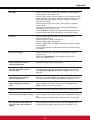
7URXEOHVKRRWLQJ
0HQX7UHH
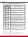
,QGLFDWRUVDQG3URMHFWRU&RQGLWLRQ
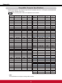
&RPSDWLEOH&RPSXWHU6SHFLILFDWLRQV
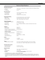
Technical Specifications
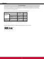
3-/LQN1RWLFH
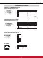
&RQILJXUDWLRQVRI7HUPLQDOV
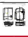
'LPHQVLRQV
Serial Control Interface
Basic Operation . . . . . . . . . . . . . . . . . . . . . .18
7XUQLQJ2QWKH3URMHFWRU
7XUQLQJ2IIWKH3URMHFWRU
+RZWR2SHUDWHWKH2Q6FUHHQ0HQX
Menu Bar
=RRPDQG)RFXV$GMXVWPHQW
$XWR6HWXS)XQFWLRQ
.H\VWRQH&RUUHFWLRQ
6RXQG$GMXVWPHQW
Information . . . . . . . . . . . . . . . . . . . . . . . . . .58
Installation. . . . . . . . . . . . . . . . . . . . . . . . . . .13
6HWWLQJXS
&RQQHFWLQJWRD&RPSXWHU
Connecting to Video Equipment
Connecting to Component Video and RGB
6FDUW(TXLSPHQW
Using the Ferrite Core
Connecting the AC Power Cord
27
Video Input . . . . . . . . . . . . . . . . . . . . . . . . . .36
Compliance . . . . . . . . . . . . . . . . . . . . . . . . . . .7
Contents of package
25
22
71
75
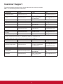
Customer Support . . . . . . . . . . . . . . . . . . . .77
Limited Warranty . . . . . . . . . . . . . . . . . . . . .78
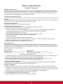
Trademarks
Each name of corporations or products in this book is either a registered trademark or a trademark of its respective
corporation.
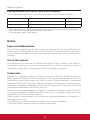
To the Owner
Before installing and operating this projector, read this
manual thoroughly.
This projector provides many convenient features and
functions. Operating the projector properly enables
you to manage those features and maintains it in good
condition for many years to come.
Improper operation may result in not only shortening the
SURGXFWOLIHEXWDOVRPDOIXQFWLRQVILUHKD]DUGRURWKHU
accidents.
If your projector seems to operate improperly, read this
manual again, check operations and cable connections
and try the solutions in the “Troubleshooting” section on
SDJHVRIWKLVPDQXDO,IWKHSUREOHPVWLOOSHUVLVWV
contact the dealer where you purchased the projector or
the service center.
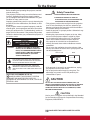
Safety Precaution
WARNING:
ELECTRIC SHOCK, DO NOT EXPOSE THIS
APPLIANCE TO RAIN OR MOISTURE.
±7KLVSURMHFWRUSURGXFHVLQWHQVHOLJKWIURPWKHSURMHFWLRQ
lens. Do not stare directly into the lens, otherwise eye
damage could result. Be especially careful that children
do not stare directly into the beam.
±,QVWDOOWKHSURMHFWRULQDSURSHUSRVLWLRQ2WKHUZLVHLWPD\
UHVXOWLQILUHKD]DUG
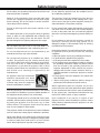
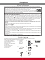
±$OORZLQJWKHSURSHUDPRXQWRIVSDFHRQWKHWRSVLGHV
and rear of the projector cabinet is critical for proper
air circulation and cooling of the unit. The dimension
shown here indicate the minimum space required.
If the projector is to be built into a compartment or
similarly enclosed, these minimum distances must be
maintained.
±'RQRWFRYHUWKHYHQWLODWLRQVORWRQWKHSURMHFWRU+HDW
EXLOGXSFDQUHGXFHWKHVHUYLFHOLIHRI\RXUSURMHFWRUDQG
can also be dangerous.
CAUTION
RISK OF ELECTRIC SHOCK
DO NOT OPEN
CAUTION:
Ɣ THIS APPARATUS MUST BE EARTHED.
Ɣ TO REDUCE THE RISK OF FIRE OR
TO REDUCE THE RISK OF ELECTRIC
SHOCK, DO NOT REMOVE COVER (OR
BACK). NO USER-SERVICEABLE PARTS
INSIDE EXCEPT LAMP REPLACEMENT.
REFER SERVICING TO QUALIFIED
SERVICE PERSONNEL.
SIDE and TOP
REAR
0.7’(20cm)
7+,66<0%2/,1',&$7(67+$7'$1*(5286
92/7$*(&2167,787,1*$5,6.2)(/(&75,&
SHOCK IS PRESENT WITHIN THIS UNIT.
1.5’(50cm)
7+,66<0%2/,1',&$7(67+$77+(5($5(
IMPORTANT OPERATING AND MAINTENANCE
INSTRUCTIONS IN THE USER GUIDE WITH THIS
UNIT.
3’(1m)
3’(1m)
±,IWKHSURMHFWRULVXQXVHGIRUDQH[WHQGHGWLPHXQSOXJ
the projector from the power outlet.
±'RQRWSURMHFWWKHVDPHLPDJHIRUDORQJWLPH7KH
DIWHULPDJHPD\UHPDLQRQWKH/&'SDQHOVE\WKH
characteristic of panel.
NOTE FOR CUSTOMERS IN THE US
+J/$036,16,'(7+,6352'8&7&217$,1
0(5&85<$1'0867%(5(&<&/('25
',6326('2)$&&25',1*72/2&$/67$7(25
)('(5$//$:6
CAUTION
DO NOT SET THE PROJECTOR IN GREASY, WET, OR
SMOKY CONDITIONS SUCH AS IN A KITCHEN TO PREVENT
A BREAKDOWN OR A DISASTER. IF THE PROJECTOR
COMES IN CONTACT WITH OIL OR CHEMICALS, IT MAY
BECOME DETERIORATED.
CAUTION
Not for use in a computer room as defined in the Standard
for the Protection of Electronic Computer/Data Processing
Equipment, ANSI/NFPA 75.
READ AND KEEP THIS USER GUIDE FOR LATER
USE.
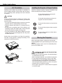
Safety Instructions
All the safety and operating instructions should be read
before the product is operated.
Do not install the projector near the ventilation duct of
DLUFRQGLWLRQLQJHTXLSPHQW
Read all of the instructions given here and retain them
for later use. Unplug this projector from AC power supply
before cleaning. Do not use liquid or aerosol cleaners.
Use a damp cloth for cleaning.
This projector should be operated only from the type
of power source indicated on the marking label. If you
are not sure of the type of power supplied, consult your
DXWKRUL]HGGHDOHURUORFDOSRZHUFRPSDQ\
Follow all warnings and instructions marked on the
projector.
'RQRWRYHUORDGZDOORXWOHWVDQGH[WHQVLRQFRUGVDVWKLV
can result in fire or electric shock. Do not allow anything
to rest on the power cord. Do not locate this projector
where the cord may be damaged by persons walking on
it.
For added protection to the projector during a lightning
storm, or when it is left unattended and unused for long
periods of time, unplug it from the wall outlet. This will
prevent damage due to lightning and power line surges.
'R QRW H[SRVH WKLV XQLW WR UDLQ RU XVH QHDU ZDWHU IRU
H[DPSOHLQDZHWEDVHPHQWQHDUDVZLPPLQJSRROHWF
Do not attempt to service this projector yourself as
RSHQLQJ RU UHPRYLQJ &RYHUV PD\ H[SRVH \RX WR
GDQJHURXV YROWDJH RU RWKHU KD]DUGV 5HIHU DOO VHUYLFLQJ
to qualified service personnel.
Unplug this projector from wall outlet and refer servicing
to qualified service personnel under the following
conditions:
a. When the power cord or plug is damaged or frayed.
b. If liquid has been spilled into the projector.
F,IWKHSURMHFWRUKDVEHHQH[SRVHGWRUDLQRUZDWHU
d. If the projector does not operate normally by following
the operating instructions. Adjust only those controls
that are covered by the operating instructions as
improper adjustment of other controls may result in
GDPDJH DQG ZLOO RIWHQ UHTXLUH H[WHQVLYH ZRUN E\ D
qualified technician to restore the projector to normal
operation.
e. If the projector has been dropped or the cabinet has
been damaged.
I :KHQ WKH SURMHFWRU H[KLELWV D GLVWLQFW FKDQJH LQ
SHUIRUPDQFHWKLVLQGLFDWHVDQHHGIRUVHUYLFH
Do not use attachments not recommended by the
PDQXIDFWXUHUDVWKH\PD\FDXVHKD]DUGV
Do not place this projector on an unstable cart, stand,
or table. The projector may fall, causing serious injury
to a child or adult, and serious damage to the projector.
Use only with a cart or stand recommended by the
manufacturer, or sold with the projector. Wall or shelf
mounting should follow the manufacturer’s instructions,
and should use a mounting kit approved by the
manufacturers.
An appliance and cart combination
should be moved with care. Quick
VWRSV H[FHVVLYH IRUFH DQG XQHYHQ
surfaces may cause the appliance
and cart combination to overturn.
When replacement parts are required, be sure the
service technician has used replacement parts specified
by the manufacturer that have the same characteristics
DV WKH RULJLQDO SDUW 8QDXWKRUL]HG VXEVWLWXWLRQV PD\
result in fire, electric shock, or injury to persons.
Slots and openings in the back and bottom of the cabinet
are provided for ventilation, to ensure reliable operation of
the equipment and to protect it from overheating.
The openings should never be covered with cloth or other
materials, and the bottom opening should not be blocked
by placing the projector on a bed, sofa, rug, or other
similar surface. This projector should never be placed
near or over a radiator or heat register.
Upon completion of any service or repairs to this
projector, ask the service technician to perform routine
safety checks to determine that the projector is in safe
operating condition.
7KLVSURMHFWRUVKRXOGQRWEHSODFHGLQDEXLOWLQLQVWDOODWLRQ
such as a book case unless proper ventilation is provided.
Never push objects of any kind into this projector through
cabinet slots as they may touch dangerous voltage points
or short out parts that could result in a fire or electric
shock. Never spill liquid of any kind on the projector.
5
Safety Instructions
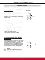
Air Circulation
Installing the Projector in Proper Position
Openings in the cabinet are provided for ventilation. To
ensure reliable operation of the product and to protect it
from overheating, these openings must not be blocked
or covered.
Install the projector properly. Improper installation may
UHGXFHWKHODPSOLIHDQGFDXVHDILUHKD]DUG
'RQRWUROOWKHSURMHFWRUPRUHWKDQ
degrees from side to side.
CAUTION
'RQRWSLWFKWKHSURMHFWRUPRUHWKDQ
degrees from above and below.
+RWDLULVH[KDXVWHGIURPWKHH[KDXVWYHQW:KHQXVLQJ
or installing the projector, the following precautions
should be taken.
±'RQRWSXWDQ\IODPPDEOHREMHFWRUVSUD\FDQQHDUWKH
SURMHFWRUKRWDLULVH[KDXVWHGIURPWKHDLUYHQWV
±.HHSWKHH[KDXVWYHQWDWOHDVW¶PDZD\IURPDQ\
objects.
±'R QRW WRXFK D SHULSKHUDO SDUW RI WKH H[KDXVW YHQW
especially screws and metallic parts. These areas will
become hot while the projector is being used.
±'RQRWSXWDQ\WKLQJRQWKHFDELQHW2EMHFWVSXWRQWKH
cabinet will not only get damaged but also may cause
ILUHKD]DUGE\KHDW
Do not point the projector up to project an
image.
Do not point the projector down to project
an image.
Do not put the projector on either side to
project an image.
Cooling fans are provided to cool down the projector.
The fans’ running speed is changed according to the
temperature inside the projector.
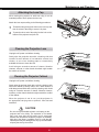
Moving the Projector
When moving the projector, replace the lens cap and
retract adjustable foot to prevent damage to the lens and
cabinet.
:KHQWKHSURMHFWRULVQRWLQXVHIRUDQH[WHQGHGSHULRG
put it into a suitable case.
Air Intake Vent
CAUTION IN CARRYING OR TRANSPORTING
THE PROJECTOR
±'RQRWGURSRUEXPSWKHSURMHFWRURWKHUZLVHGDPDJHV
or malfunctions may result.
±:KHQFDUU\LQJWKHSURMHFWRUXVHDVXLWDEOHFDUU\LQJFDVH
±'RQRWWUDQVSRUWWKHSURMHFWRUE\FRXULHURUDQ\RWKHU
transport service in an unsuitable transport case. This
may cause damage to the projector. For information
about transporting the projector by courier or any other
transport service, consult your dealer.
± 'RQRWSXWWKHSURMHFWRULQDFDVHEHIRUHWKHSURMHFWRU
is cooled enough.
Air Intake Vent
([KDXVW9HQW
+RWDLUH[KDXVW
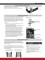
Compliance
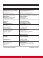
AC Power Cord Requirement
The AC Power Cord supplied with this projector meets the requirement for use in the country you purchased it.
AC Power Cord for the United States and Canada:
AC Power Cord used in the United States and Canada is listed by the Underwriters
/DERUDWRULHV8/DQGFHUWLILHGE\WKH&DQDGLDQ6WDQGDUG$VVRFLDWLRQ&6$
$&3RZHU&RUGKDVDJURXQGLQJW\SH$&OLQHSOXJ7KLVLVDVDIHW\IHDWXUHWREHVXUHWKDWWKH
plug will fit into the power outlet. Do not try to defeat this safety feature. Should you be unable
to insert the plug into the outlet, contact your electrician.
GROUND
AC Power Cord for the United Kingdom:
This cord is already fitted with a moulded plug incorporating a fuse, the value of which is indicated on the pin
IDFHRIWKHSOXJ6KRXOGWKHIXVHQHHGWREHUHSODFHGDQ$67$DSSURYHG%6IXVHPXVWEHXVHGRIWKH
same rating, marked thus . If the fuse cover is detachable, never use the plug with the cover omitted. If a
replacement fuse cover is required, ensure it is of the same colour as that visible on the pin face of the plug
(i.e. red or orange). Fuse covers are available from the Parts Department indicated in your User Instructions.
If the plug supplied is not suitable for your socket outlet, it should be cut off and destroyed.
7KHHQGRIWKHIOH[LEOHFRUGVKRXOGEHVXLWDEO\SUHSDUHGDQGWKHFRUUHFWSOXJILWWHG
WARNING : A PLUG WITH BARED FLEXIBLE CORD IS HAZARDOUS IF ENGAGED IN A LIVE SOCKET
OUTLET.
The Wires in this mains lead are coloured in accordance with the following code:
*UHHQDQG\HOORZ Earth
Blue . . . . . . . . . . . Neutral
Brown . . . . . . . . . /LYH
As the colours of the wires in the mains lead of this apparatus may not correspond with the coloured markings
identifying the terminals in your plug proceed as follows:
7KHZLUHZKLFKLVFRORXUHGJUHHQDQG\HOORZPXVWEHFRQQHFWHGWRWKHWHUPLQDOLQWKHSOXJZKLFKLVPDUNHGE\
the letter E or by the safety earth symbol RUFRORXUHGJUHHQRUJUHHQDQG\HOORZ
The wire which is coloured blue must be connected to the terminal which is marked with the letter N or
coloured black.
7KH ZLUH ZKLFK LV FRORXUHG EURZQ PXVW EH FRQQHFWHG WR WKH WHUPLQDO ZKLFK LV PDUNHG ZLWK WKH OHWWHU / RU
coloured red.
WARNING: THIS APPARATUS MUST BE EARTHED.
ASA
THE SOCKET-OUTLET SHOULD BE INSTALLED NEAR THE EQUIPMENT AND EASILY ACCESSIBLE.
Contents of package
Your projector should come with the items shown below. Check that all the items are included.
Require of your dealer immediately if any items are missing.
8VHU*XLGH&'520[
4XLFN6WDUW*XLGH%RRN[
$&3RZHU&RUG
5HPRWH&RQWURODQG%DWWHULHV
(5) VGA Cable
/HQV&DSZLWK6WULQJ
3,1&RGH/DEHO
)HUULWHFRUH
(1)
(7)
(2)
(5)
7
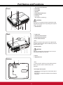
Part Names and Functions
① Top controls and Indicators
② Zoom Ring
③ Focus Ring
④ Speaker
⑤ Infrared Remote Receiver
⑥ Projection Lens
⑦ Lens Cap
6HHSDJHIRUDWWDFKLQJ
Front
①
② ③
CAUTION
Do not turn on a projector with lens cap attached. High
temperature from light beam may damage lens cap and
UHVXOWLQILUHKD]DUG
⑧ Air Intake Vent
④
⑤
⑥
⑦
⑧
⑨ Lamp Cover
⑩ Terminals and Connectors
⑪ LAN Connection Terminal
⑫ Power Cord Connector
Back
⑨
⑩
⑪
3Note:
Replace only with the same types of the supplied cords
or cables. Using improper cords or cables may cause an
electric shock or a fire.
⑬ Exhaust Vents
CAUTION
⑫⑬
⑬
¼
⑭
+RWDLULVH[KDXVWHGIURPWKHH[KDXVWYHQW'RQRWSXW
KHDWVHQVLWLYHREMHFWVQHDUWKLVVLGH
⑧
⑭ Filters
⑮ Adjustable Foot
Bottom
⑭
⑮
3Note:
⑪/$1&RQQHFWLRQ7HUPLQDOLVIRUWKH1HWZRUNIXQFWLRQ
5HIHUWRWKH8VHU*XLGHRI³1HWZRUN6HWXSDQG
Operation” .
¼Kensington Security Slot
This slot is for a Kensington lock used to deter theft of
the projector.
Kensington is a registered trademark of ACCO Brands
Corporation.
Part Names and Functions
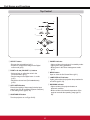
Rear Terminal
①
②
③
⑤
⑦
⑧
⑥
④
① CONTROL PORT
When the projector is controlled by a computer,
connect to this jack with serial control cable.
⑤ VIDEO IN
Connect the composite video output signal to this
jack (p.15).
② COMPUTER IN 1 /S-VIDEO IN / COMPONENT IN
Connect output signal from a computer, component
YLGHRRXWSXW5*%VFDUWSLQYLGHRRXWSXWRU
6YLGHRRXWSXWWRWKLVWHUPLQDOSS
⑥ LAN Connection Terminal
&RQQHFWWKH/$1FDEOHUHIHUWRWKH8VHU*XLGHRI
³1HWZRUN6HWXSDQG2SHUDWLRQ´
③
⑦ AUDIO IN(Video)
Connect the audio output signal from video
equipment connected to ⑤ to this jack. For a mono
audio signal (a single audio jack), connect it to
/0212MDFNSS
COMPUTER IN 2 / MONITOR OUT
±&RQQHFWDQDORJ5*%RXWSXWVLJQDOIURPD
FRPSXWHUWRWKLVWHUPLQDOS
±7KLVWHUPLQDOFDQEHXVHGWRRXWSXWWKHLQFRPLQJ
analog RGB and Component signal from
&20387(5,169,'(2,1&20321(17,1
WHUPLQDOWRWKHRWKHUPRQLWRUSS
⑧ AUDIO IN (PC)
Connect the audio output signal from computer
or video equipment connected to ② and ③ to this
MDFNSS
④ AUDIO OUT (VARIABLE)
&RQQHFWDQH[WHUQDODXGLRDPSOLILHUWRWKLVMDFN
SS
This terminal outputs sound from AUDIO IN
terminal.
Never plug headphones into this jack.
Part Names and Functions
Top Control
⑤
⑧
④
⑦
③
②
①
⑥
① SELECT button
±([HFXWHWKHVHOHFWHGLWHPS
±([SDQGRUFRPSUHVVWKHLPDJHLQWKH'LJLWDO
]RRPPRGHS
⑤
② POINT ŸźŻŹ (VOLUME –/+) buttons
±6HOHFWDQLWHPRUDGMXVWWKHYDOXHLQWKH
2Q6FUHHQ0HQXS
±3DQWKHLPDJHLQWKH'LJLWDO]RRPPRGH
S
±$GMXVWWKHYROXPHOHYHO3RLQWŻŹbuttons)
S
POWER indicator
±/LJKWVUHGZKHQWKHSURMHFWRULVLQVWDQGE\PRGH
±/LJKWVJUHHQGXULQJRSHUDWLRQV
±%OLQNVJUHHQLQWKH3RZHUPDQDJHPHQWPRGH
S
⑥ MENU button
2SHQRUFORVHWKH2Q6FUHHQ0HQXS
⑦ LAMP REPLACE indicator
/LJKWV\HOORZZKHQWKHSURMHFWLRQODPSUHDFKHVLWV
HQGRIOLIHSS
⑧ WARNING indicator
±/LJKWVUHGZKHQWKHSURMHFWRUGHWHFWVDQ
abnormal condition.
±%OLQNVUHGZKHQWKHLQWHUQDOWHPSHUDWXUHRIWKH
SURMHFWRUH[FHHGVWKHRSHUDWLQJUDQJHSS
③ AUTO SETUP button
([HFXWHWKHVHWWLQJRI$XWRVHWXSLQFOXGHV,QSXW
search, Auto PC adj. and Auto Keystone functions)
in the setting menu.SS
④ ON/STAND–BY button
7XUQWKHSURMHFWRURQRURIISS
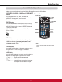
Part Names and Functions
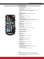
Remote Control
① ON/STAND-BY button
7XUQWKHSURMHFWRURQRURIISS
② AUTO SET button
([HFXWHWKHVHWWLQJRI$XWRVHWXSLQFOXGHV,QSXWVHDUFK$XWR3&DGM
and Auto Keystone functions) in the setting menu.
SS
③ COMPUTER 1/2 buttons
Select the COMPUTER 1 or COMPUTER 2 input source.
SS
②
①
③
④
⑳
⑲
⑤
⑥
⑦
⑱
⑧
⑰
⑨
⑯
⑮
⑭
⑩
⑪
⑬
④ VIDEO button
6HOHFWWKH9,'(2LQSXWVRXUFHS
⑤ S-VIDEO button
6HOHFWWKH69,'(2LQSXWVRXUFHS
⑥ Point ŸźŻŹ buttons
±6HOHFWDQLWHPRUDGMXVWWKHYDOXHLQWKH2Q6FUHHQ0HQXS
±3DQWKHLPDJHLQWKH'LJLWDO]RRPPRGHS
⑦ SCREEN button
6HOHFWDVFUHHQPRGHSS
⑧ MENU button
2SHQRUFORVHWKH2Q6FUHHQ0HQXS
⑨ FREEZE button
)UHH]HWKHSLFWXUHRQWKHVFUHHQS
⑩ NO SHOW button
7HPSRUDULO\WXUQRIIWKHLPDJHRQWKHVFUHHQS
⑪ D.ZOOM Ÿź buttons
=RRPLQDQGRXWWKHLPDJHVSS
⑫ VOLUME +/- buttons
Adjust the volume level.S
⑫
⑬ MUTE button
0XWHWKHVRXQGS
⑭ IMAGE button
6HOHFWWKHLPDJHPRGHSS
⑮ P-TIMER button
2SHUDWHWKH3WLPHUIXQFWLRQSS
⑯ LAMP button
6HOHFWDODPSPRGHSS
⑰ INFO. button
2SHUDWHWKHLQIRUPDWLRQIXQFWLRQS
⑱ KEYSTONE button
&RUUHFWNH\VWRQHGLVWRUWLRQSS
⑲ SELECT button
±([HFXWHWKHVHOHFWHGLWHPS
±([SDQGRUFRPSUHVVWKHLPDJHLQ'LJLWDO]RRPPRGHS
⑳ COMPONENT button
Select the COMPONENT input source. S
3Note:
To ensure safe operation, please observe the following precautions:
± 'RQRWEHQGGURSRUH[SRVHWKHUHPRWHFRQWUROWRPRLVWXUHRUKHDW
± )RUFOHDQLQJXVHDVRIWGU\FORWK'RQRWDSSO\EHQ]HQHWKLQQHUVSUD\
or any chemical material.
11
Part Names and Functions
Remote Control Battery Installation
1
Open the battery
compartment lid.
2
Install new batteries
into the compartment.
3
Replace the
compartment lid.
Two AAA size batteries
For correct polarity
DQG±EHVXUH
battery terminals are
in contact with pins in
compartment.
To ensure safe operation, please observe the following precautions :
Ɣ 8VHWZR$$$RU/5W\SHDONDOLQHEDWWHULHV
Ɣ Always replace batteries in sets.
Ɣ Do not use a new battery with a used battery.
Ɣ Avoid contact with water or liquid.
Ɣ 'RQRWH[SRVHWKHUHPRWHFRQWUROWRPRLVWXUHRUKHDW
Ɣ Do not drop the remote control.
Ɣ If the battery has leaked on the remote control, carefully wipe the case clean and install new batteries.
Ɣ 5LVNRIDQH[SORVLRQLIEDWWHU\LVUHSODFHGE\DQLQFRUUHFWW\SH
Ɣ Dispose of used batteries according to the instructions or your local disposal rule or guidelines.
Remote Control Operating Range
Point the remote control toward the projector (Infrared
5HPRWH 5HFHLYHU ZKHQ SUHVVLQJ WKH EXWWRQV 0D[LPXP
RSHUDWLQJ UDQJH IRU WKH UHPRWH FRQWURO LV DERXW P
DQGGHJUHHVLQIURQWRIWKHSURMHFWRU
(5 m)
Remote control
Remote Control Code
7KH GLIIHUHQW UHPRWH FRQWURO FRGHV &RGH ±&RGH DUH
assigned to this projector. Switching the remote
control codes prevents interference from other remote
controls when several projectors or video equipment
QH[W WR HDFK RWKHU DUH RSHUDWHG DW WKH VDPH WLPH &KDQJH
the remote control code for the projector first before
changing that for the remote control. See "Remote control"
LQWKH6HWWLQJ0HQXRQSDJH
MENU button
IMAGE button
Press and hold the MENU and IMAGE buttons for more
than five seconds to switch between the Code 1 and Code
2. The initial code is set to Code 1.
Adjustable Foot
3URMHFWLRQDQJOHFDQEHDGMXVWHGXSWRGHJUHHVZLWK
the adjustable foot.
/LIWWKHIURQWRIWKHSURMHFWRUDQGSXVKWKHIRRWORFNODWFKRQ
the projector.
Release the foot lock latch to lock the adjustable foot and
rotate the adjustable foot to adjust the position and
tilt.
To retract the adjustable foot, lift the front of the projector
and push and undo the foot lock latch.
Keystone distortion of the projected image can be corrected
E\PHQXRSHUDWLRQVHHSDJHV
12
)RRW/RFN/DWFK
Adjustable Foot
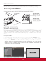
Installation
Setting up
Install the projector according to the environment and manner the projector will be used in.
For the case of installation in a special state such as ceiling mount, the specified mounting accessories and service
may be required. Before installing the projector, consult your dealer about your installation.
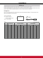
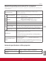
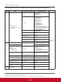
Arrangement
Refer to the following tables T-1 to determine the screen size and projection distance. The values shown in the
table are calculated for a full size screen.
(H) x (V) : Screen size
(a) : Projection distance
(from the projectior’s end)
(H)
(a)
(b)
(V)
(b), (c) : Screen height
(c)
(1024X768) (±10%)
T- 1
Screen
Type
4:3
inch
40
50
60
70
80
90
100
120
150
200
250
300
Screen size
(H)
m
0.8
1.0
1.2
1.4
1.6
1.8
2.0
2.4
3.0
4.1
5.1
6.1
(V)
m
0.6
0.8
0.9
1.1
1.2
1.4
1.5
1.8
2.3
3.0
3.8
4.6
Projection distance
(a) min.
m
inch
1.3
51
1.6
64
1.9
77
2.3
89
2.6
102
2.9
115
3.3
128
3.9
154
4.9
193
6.5
258
8.2
323
9.8
387
(a) max
m
inch
1.6
61
1.9
77
2.3
92
2.7
108
3.1
123
3.5
139
3.9
154
4.7
186
5.9
232
7.9
310
9.8
388
11.8
466
13
Screen height
(b)
cm
52
65
78
91
105
118
131
157
196
261
327
392
(c)
inch
20
26
31
36
41
46
52
62
77
103
129
154
cm
-9
-11
-13
-15
-17
-20
-22
-26
-33
-44
-54
-65
inch
-4
-4
-5
-6
-7
-8
-9
-10
-13
-17
-21
-26
Installation
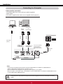
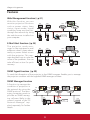
Connecting to a Computer
Cables used for connection
9*$&DEOHV0LQL'VXESLQ2QO\RQHFDEOHLVVXSSOLHG
$XGLR&DEOHV
(2QHFDEOHLVVXSSOLHGRWKHUcables are not supplied with the projector.)
Audio Output
Monitor
Output
Monitor Input
or
Monitor Output
([WHUQDO$XGLR(TXLSPHQW
VGA
cable
VGA
cable
Audio cable
(stereo)
Audio Input
COMPUTER IN 1
69,'(2,1
/COMPONENT IN
COMPUTER IN 2 /
MONITOR OUT
This terminal is switchable.
Set up the terminal as
either Computer input or
Monitor output. (See Page
Audio cable
(stereo)
AUDIO OUT
(stereo)
AUDIO IN
3Note:
,QSXWVRXQGWRWKH$8',2,1WHUPLQDOZKHQXVLQJWKH&20387(5,169,'(2,1&20321(17,1
and the COMPUTER IN 2/MONITOR OUT terminals as input.
:KHQWKH$8',2287LVSOXJJHGLQWKHSURMHFWRU
VEXLOWLQVSHDNHULVQRWDYDLODEOH
:KHQWKHFDEOHLVRIWKHORQJHUYDULHW\LWLVDGYLVDEOHWRXVHWKH&20387(5,169,'(2,1&20321(17,1DQG
not the COMPUTER IN 2/MONITOR OUT.
8QSOXJWKHSRZHUFRUGVRIERWKWKHSURMHFWRUDQGH[WHUQDOHTXLSPHQWIURPWKH$&RXWOHWEHIRUHFRQQHFWLQJ
cables.
Installation
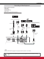
Connecting to Video Equipment
Cables used for connection
9LGHR&DEOH
69LGHR&DEOH
69LGHR9*$&DEOH
$XGLR&DEOHV
(Cables are not supplied with the projector. )
69LGHR2XWSXWDQG$XGLRRXWSXW
Composite Video and Audio Output
([WHUQDO$XGLR(TXLSPHQW
69LGHRFDEOH
Audio
cable
(stereo)
Audio
cable
(stereo)
69LGHR9*$
cable
COMPUTER IN 1
69,'(2,1
/COMPONENT IN
AUDIO IN
AUDIO IN
Video cable
VIDEO IN
Audio Input
Audio cable
(stereo)
AUDIO OUT
(stereo)
3Note:
:KHQWKH$8',2287LVSOXJJHGLQWKHSURMHFWRU
VEXLOWLQVSHDNHULVQRWDYDLODEOH
8QSOXJWKHSRZHUFRUGVRIERWKWKHSURMHFWRUDQGH[WHUQDOHTXLSPHQWIURPWKH$&RXWOHWEHIRUHFRQQHFWLQJ
cables.
15
Installation
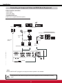
Connecting to Component Video and RGB (Scart) Equipment
Cables used for connection
$XGLR&DEOHV
6FDUW9*$&DEOH
&RPSRQHQW&DEOH
&RPSRQHQW9*$&DEOH
(Cables are not supplied with this projector.)
Audio Output
5*%6FDUW
pin Output
Component Video Output
(Y, Pb/Cb, Pr/Cr)
Component
cable
Audio Input
([WHUQDO$XGLR(TXLSPHQW
6FDUW9*$
cable
Audio cable
(stereo)
Audio cable
(stereo)
&RPSRQHQW
VGA cable
AUDIO OUT
(stereo)
&20387(5,169,'(2,1&20321(17,1
AUDIO IN
3Note:
:KHQWKH$8',2287LVSOXJJHGLQWKHSURMHFWRU
VEXLOWLQVSHDNHULVQRWDYDLODEOH
8QSOXJWKHSRZHUFRUGVRIERWKWKHSURMHFWRUDQGH[WHUQDOHTXLSPHQWIURPWKH$&RXWOHWEHIRUHFRQQHFWLQJ
cables.
Installation
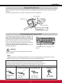
Using the Ferrite Core
Before using the AC Power Cord, attach the ferrite core (supplied) as shown below. (See below for mounting
location.)
The Power Cord with ferrite core must be used for RF interference suppression.
PP
Ferrite Core
AC Power Cord
Keep closing until it makes
a clicking sound.
Connecting the AC Power Cord
7KLVSURMHFWRUXVHVQRPLQDOLQSXWYROWDJHVRI9$&
and it automatically selects the correct input voltage. It is
GHVLJQHGWRZRUNZLWKVLQJOHSKDVHSRZHUV\VWHPVKDYLQJD
grounded neutral conductor. To reduce the risk of electrical
shock, do not plug into any other type of power system.
If you are not sure of the type of power being supplied,
FRQVXOW\RXUDXWKRUL]HGGHDOHURUVHUYLFHFHQWHU
Connect the projector with all peripheral equipment before
turning the projector on.
Connect the AC power cord (supplied) to the
projector.
CAUTION
The AC outlet must be near this equipment and must be
easily accessible.
3Note:
Unplug the AC power cord when the projector is not in use. When this projector is connected to an outlet
ZLWKWKH$&SRZHUFRUGLWLVLQ6WDQGE\PRGHDQGFRQVXPHVDOLWWOHHOHFWULFSRZHU
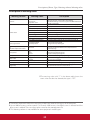
NOTE ON THE POWER CORD
AC power cord must meet requirement of the country where you use the projector.
Confirm the AC plug type with the chart below and proper AC power cord must be used.
If supplied AC power cord does not match your AC outlet, contact your sales dealer.
Projector side
AC outlet side
For the U.S.A. and Canada
For Continental Europe
For the U.K.
Ground
¹
Ground
º
To power cord
connector on your
projector.
To the AC outlet.
(120 V AC)
To the AC outlet.
(200 - 240 V AC)
17
To the AC outlet.
(200 - 240 V AC)
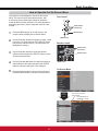
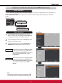
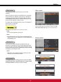
Basic Operation
Turning On the Projector
1
Complete peripheral connections (with a computer,
VCR, etc.) before turning on the projector.
2
Connect the projector’s AC power cord into an AC
outlet. The POWER indicator lights red. Open the lens
FDSVHHSDJHV
3
3UHVVWKH2167$1'%<EXWWRQRQWKHWRSFRQWURORU
on the remote control. The POWER indicator lights
green and the cooling fans start to operate. The
preparation display appears on the screen.
4
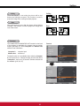
$IWHUDERXWVHFRQGVWKHLQSXWVRXUFHWKDWZDV
selected the last time and the lamp control status icon
VHHSDJHDSSHDURQWKHVFUHHQ
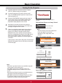
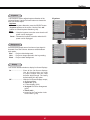
5
If there is no signal input when start on the projector,
or the current signal is missed while operating the
projector, the Video/PC selection window will be
displayed on the screen, please move the pointer to
input source desired by pressing the Point Ÿź buttons
DQGSUHVVWKH6(/(&7EXWWRQ$QGWKHQIROORZWKH
input signal guidance window to correct the signal and
connection.
7KHSUHSDUDWLRQGLVSOD\ZLOOGLVDSSHDUDIWHU
seconds.
Selected Input Source and Lamp Control
Video
/DPSFRQWUROVWDWXV
6HHSDJHIRU/DPSFRQWUROVWDWXV
3Note:
7KH)LOWHUZDUQLQJDQG/DPSUHSODFHPHQW
icons may appear on the screen
depending on the usage state of the
projector.
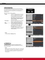
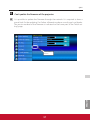
Video / PC selection window
ProjectVideo
Video
Project
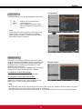
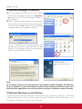
If the projector is locked with a PIN code, PIN code input
GLDORJER[ZLOODSSHDU(QWHUWKH3,1FRGHDVLQVWUXFWHG
RQWKHQH[WSDJH
Project Computer
Cancel
Input signal guidance window
No signal
Current Input setting:Video
Is signal processed correctly?
Is cable connected properly?
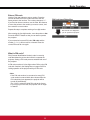
Video / PC selection window
Project Video
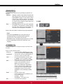
3Note:
Project Computer
:KHQWKH/RJRVHOHFWIXQFWLRQLVVHWWROff, the logo will
QRWEHVKRZQRQWKHVFUHHQS
:KHQOff is selected in the Display function, the
preparation display will not be shown on the screen
S
:KHQWKH,QSXW6HDUFKIXQFWLRQLVVHWWROn2, the input
VLJQDOZLOOEHVHDUFKHGDXWRPDWLFDOO\S
:KHQOff is selected in the Display function, the Video/
PC selection window and the input signal guidance
ZLQGRZDUHQRWVKRZQRQWKHVFUHHQS
Cancel
Input signal guidance window
No signal
Current Input setting:RGB
Is signal processed correctly?
Is cable connected properly?
Basic Operation
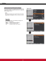
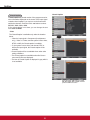
Enter a PIN code
Use the Point Ÿź buttons to enter a number. Press the
Point Ż ŹEXWWRQVWRIL[WKHQXPEHUDQGPRYHWKHUHG
IUDPHSRLQWHUWRWKHQH[WER[7KHQXPEHUFKDQJHVWR³¼”.
,I\RXIL[HGDQLQFRUUHFWQXPEHUXVHWKH3RLQWŻ Ź buttons
to move the pointer to the number you want to correct, and
then enter the correct number.
5HSHDWWKLVVWHSWRFRPSOHWHHQWHULQJDIRXUGLJLWQXPEHU
$IWHUHQWHULQJWKHIRXUGLJLWQXPEHUPRYHWKHSRLQWHUWRSet.
3UHVVWKH6(/(&7EXWWRQVRWKDW\RXFDQVWDUWWRRSHUDWH
the projector.
If you entered an incorrect PIN code, PIN code and the
number (¼¼¼¼) will turn red for a moment. Enter the
correct PIN code all over again.
What is PIN code?
PIN (Personal Identification Number) code is a security
code that allows the person who knows it to operate the
SURMHFWRU6HWWLQJD3,1FRGHSUHYHQWVXQDXWKRUL]HGXVHRI
the projector.
$3,1FRGHFRQVLVWVRIDIRXUGLJLWQXPEHU5HIHUWRWKH3,1
FRGHORFNIXQFWLRQLQWKH6HWWLQJ0HQXRQSDJHVIRU
locking operation of the projector with your PIN code.
3Note:
,IWKH3,1FRGHQXPEHULVQRWHQWHUHGRUZURQJ3,1
code number is entered within three minutes after the
3,1FRGHGLDORJER[DSSHDUHGWKHSURMHFWRUZLOOEH
turned off automatically.
7KH³´LVVHWDVWKHLQLWLDO3,1FRGHDWWKHIDFWRU\
If you forget your PIN code, the projector can no longer
be started.
PIN Code Input Dialog Box
After the OK icon disappears,
you can operate the projector.
Basic Operation
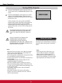
Turning Off the Projector
1
3UHVVWKH2167$1'%<EXWWRQRQWKHWRSFRQWURORU
on the remote control, and Power off? appears on the
screen.
2
3UHVVWKH2167$1'%<EXWWRQDJDLQWRWXUQRIIWKH
projector. The POWER indicator lights red and the
cooling fans stop (default setting), and you can unplug
the AC power cord.
Power off?GLVDSSHDUVDIWHUVHFRQGV
If L1LVVHOHFWHGLQ)DQPHQXSWKH32:(5
indicator starts to blink red and the cooling fans keep
UXQQLQJIRUDERXWVHFRQGVWKHQWKH32:(5
indicator lights red and the cooling fans stop. You can
unplug the AC power cord even if the cooling fans are
still running.
720$,17$,17+(/,)(2)7+(/$0321&(
YOU TURN THE PROJECTOR ON, WAIT AT
/($67),9(0,187(6%()25(7851,1*,7
OFF.
DO NOT OPERATE THE PROJECTOR
&217,18286/<:,7+2875(67
&217,1828686(0$<5(68/7,1
6+257(1,1*7+(/$03/,)(78512))7+(
352-(&725$1'/(767$1')25$%287$1
+285,1(9(5<+2856
Direct Off Function
You can disconnect the power cord from the
wall outlet or turn off the breaker even during
SURMHFWLRQZLWKRXWSUHVVLQJWKHRQVWDQGE\
button.
3Note:
3Note:
:KHQWKH'LUHFWRQIXQFWLRQLVVHWWROn, the projector
will be turned on automatically by connecting the AC
SRZHUFRUGWRDQ$&RXWOHWS
7KHUXQQLQJVSHHGRIFRROLQJIDQVLVFKDQJHGDFFRUGLQJ
to the temperature inside the projector.
'RQRWSXWWKHSURMHFWRULQDFDVHEHIRUHWKHSURMHFWRULV
cooled enough.
,IWKH:$51,1*LQGLFDWRUEOLQNVRUOLJKWVUHGVHH
³:$51,1*LQGLFDWRU´RQSDJH
:KLOHWKH32:(5LQGLFDWRULVEOLQNLQJWKHODPSLV
being cooled down and the projector cannot be turned
on. Wait until the POWER indicator stops blinking to turn
on the projector again.
7KHSURMHFWRUFDQEHWXUQHGRQDIWHUWKH32:(5
indicator lights red.
:KHQL2LVVHOHFWHGLQ)DQPHQXSDQGWKH
projector is turned on right after it turns off, it takes a
while to start projecting.
When using the Direct Off function, you
cannot restart the projector immediately
after the power is disconnected. If the
H[WHUQDOSRZHUVXSSO\LVVXGGHQO\FXWRII
the fans stop immediately. The lamp remains
high temperature and needs to be cooled.
Basic Operation
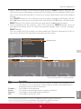
How to Operate the On-Screen Menu
7KHSURMHFWRUFDQEHDGMXVWHGRUVHWYLDWKH2Q6FUHHQ
Menu. The menus have a hierarchical structure, with
a main menu that is divided into submenus, which are
further divided into other submenus. For each adjustment
and setting procedure, refer to respective sections in this
manual.
1
Press the MENU button on the top control or the
UHPRWHFRQWUROWRGLVSOD\WKH2Q6FUHHQ0HQX
2
Use the Point Ÿź buttons to highlight or select a main
menu item. Press the Point ŹRUWKH6(/(&7button
to access the submenu items. (The selected item is
highlighted in orange.)
Top Control
POINT buttons
(arrowhead)
SELECT button
MENU button
Remote Control
POINT buttons
(arrowhead)
3
Use the Point Ÿź buttons to select the desired
VXEPHQXLWHPDQGSUHVVWKH6(/(&7EXWWRQWRVHWRU
access the selected item.
4
Use the Point ŸźŻŹbuttons to adjust the setting or
VZLWFKEHWZHHQHDFKRSWLRQDQGSUHVVWKH6(/(&7
button to activate it and return to the submenu.
5
Press the Point Żbutton to return to the main menu.
3UHVVWKH0(18EXWWRQWRH[LWWKH2Q6FUHHQ0HQX
SELECT button
MENU button
On-Screen Menu
►
Point
Red
The currently set item is
check marked.
The selected item is
highlighted in orange.
Ź or SELECT
button
►
21
Dynamic
Standard
Real
Blackboard(Green)
Colorboard
Image 1
Image 2
Image 3
Image 4
Dynamic
Standard
Real
Blackboard(Green)
Colorboard
Image 1
Image 2
Image 3
Image 4
Red
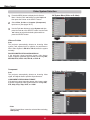
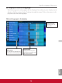
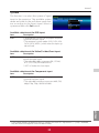
Basic Operation
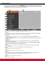
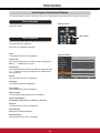
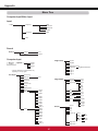
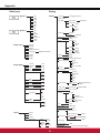
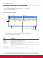
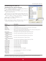
Menu Bar
)RUGHWDLOHGIXQFWLRQVRIHDFKPHQXVHH³0HQX7UHH´RQSDJHV
6XE0HQX
Main Menu
►
①
②
Computer 1
RGB
Computer 2
RGB
Video
③
④
⑤
⑥
⑦
⑧
Network
⑨
ˉˉˉ
⑩
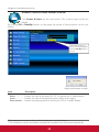
① Input
Used to select an input source from Computer 1, Computer 2 or Video SS
② PC adjust
Select Auto PC adj., Fine sync, Total dots, Horizontal, Vertical, Current mode, Clamp, Display area-H and Display
area-VWRDGMXVWWKHSDUDPHWHUVWRPDWFKZLWKWKH3&LQSXWVLJQDOIRUPDWSS
③ Image select
For computer source, used to select an image mode from among Dynamic, Standard, Real, Blackboard(Green),
Colorboard and image 1 - 4S
For Video source, used to select an image mode among Dynamic, Standard, Cinema, Blackboard(Green), Colorboard
and Image 1- 4S
④ Image adjust
For computer source, used to adjust computer image [Contrast, Brightness, Color temp., White balance (R/G/B),
Sharpness and Gamma@SS
For Video source, used to adjust picture image [Contrast, Brightness, Color, Tint, Color temp., White balance (R/G/
B), Sharpness, Gamma, Noise reduction and Progressive@SS
⑤ Screen
)RUFRPSXWHUVRXUFHXVHGWRDGMXVWVL]HRIWKHLPDJH>Normal, True, Wide, Full, Custom, Custom adj. and Digital
zoom +/–@SS
)RU9LGHRVRXUFHXVHGWRVHWVL]HRILPDJH>Normal, Wide, Custom and Custom adj.@S
⑥ Sound
8VHGWRDGMXVWWKHYROXPHRUPXWHWKHVRXQGS
⑦ Setting
8VHGWRVHWWKHSURMHFWRU¶VRSHUDWLQJFRQILJXUDWLRQVSS
⑧ Information
Display the input source information: Input , H-sync freq., V-sync freq., Screen, Language, Lamp status, Lamp
counter , Power management, Key lock, PIN code lock and Remote controlS
⑨ Network
6HHWKH8VHU*XLGHRI³1HWZRUN6HWXSDQG2SHUDWLRQ´
⑩ Guide
The key operation is displayed.
22
Basic Operation
Zoom and Focus Adjustment
5RWDWHWKH=RRP5LQJWR]RRPLQDQGRXW
Rotate the Focus Ring to adjust the focus of the image.
Zoom Ring
Focus Ring
Auto Setup Function
$XWRVHWXSIXQFWLRQLVSURYLGHGWRDXWRPDWLFDOO\H[HFXWHWKH
setting of Auto setup (includes Input search, Auto PC adj.
and Auto Keystone functions) in the setting menu by just
pressing the AUTO SETUP button on the top control or the
$8726(7EXWWRQRQWKHUHPRWHFRQWURO5HIHUWRSDJH
for the setting of the Auto setup function.
Top Control
AUTO SETUP button
POINT Ÿźbuttons
3Notes:
$XWR.H\VWRQHFRUUHFWVYHUWLFDOGLVWRUWLRQRQO\LWGRHV
QRWFRUUHFWKRUL]RQWDOGLVWRUWLRQ
$XWR.H\VWRQHFDQQRWZRUNZKHQ&HLOLQJIHDWXUHLVVHW
to OnLQWKH6HWWLQJPHQXS
3HUIHFWFRUUHFWLRQRIWKHLPDJHGLVWRUWLRQFDQQRWEH
ensured with the Auto setup function. If the distortion
cannot be corrected properly by pressing the AUTO
SETUP or AUTO SET button, adjust manually by
pressing the KEYSTONE button on the remote control
RUVHOHFWLQJ.H\VWRQHLQWKH6HWWLQJPHQXS
Fine sync, Total dots, Horizontal and Vertical
position of some computers cannot be fully adjusted
with the Auto PC Adjustment function. When the image
is not provided properly with this operation, manual
DGMXVWPHQWVDUHUHTXLUHGSS
Remote Control
AUTO SET button
POINT Ÿź buttons
KEYSTONE button
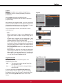
Keystone Correction
If a projected picture still has keystone distortion after
pressing the AUTO SETUP button on the top control or the
AUTO SET button on the remote control, correct the image
manually as follows:
Press the KEYSTONE button on the remote control. The
.H\VWRQHGLDORJER[DSSHDUV8VHWKH3RLQWŸź buttons to
correct keystone distortion. The keystone adjustment can be
VWRUHGVHHSDJH
Reduce the upper width
with the Point Ÿ button.
Reduce the lower width
with the Point ź button.
7KHZKLWHDUURZVLQGLFDWHWKDWWKHUHLVQR
correction.
$UHGDUURZLQGLFDWHVWKHGLUHFWLRQRIFRUUHFWLRQ
$QDUURZGLVDSSHDUVDWWKHPD[LPXPFRUUHFWLRQ
,I\RXSUHVVWKH.(<6721(EXWWRQRQWKH
remote control once more while the keystone
GLDORJER[LVEHLQJGLVSOD\HGWKHNH\VWRQH
adjustment will be canceled.
7KHDGMXVWDEOHUDQJHLVOLPLWHGGHSHQGLQJRQWKH
input signal.
Basic Operation
Sound Adjustment
Top Control
Direct Operation
Volume
VOLUME+/buttons
3UHVVWKH92/80(±EXWWRQVRQWKHWRSFRQWURORURQWKH
UHPRWHFRQWUROWRDGMXVWWKHYROXPH7KHYROXPHGLDORJER[
appears on the screen for a few seconds.
Remote Control
Mute
Press the MUTE button on the remote control to select On
to temporarily turn off the sound. To turn the sound back
on, press the MUTE button again to select Off or press the
92/80(±EXWWRQV7KH0XWHIXQFWLRQLVDOVRHIIHFWLYHIRU
the AUDIO OUT jack.
VOLUME+ button
MUTE button
VOLUME- button
Menu Operation
1
2
3UHVVWKH0(18EXWWRQWRGLVSOD\WKH2Q6FUHHQ0HQX
Use the Point Ÿź buttons to select Sound. Press the
Point Ź or WKH 6(/(&7 EXWWRQ WR DFFHVV WKH VXEPHQX
items.
Volume Dialog Box
$SSUR[LPDWHOHYHO
of the volume.
Use the Point Ÿź buttons to select the desired submenu
LWHPDQGSUHVVWKH6(/(&7EXWWRQWRDFFHVVWKH
selected item.
Volume
Press the Point Ź button to turn up the volume; press the
Point Ż button to turn down the volume.
Press the MUTE button to set the
Mute function On or Off. The dialog
ER[GLVDSSHDUVDIWHUVHFRQGV
Sound Menu
Mute
3UHVVWKH6(/(&7EXWWRQWRVZLWFKWKHPXWHIXQFWLRQOn/
Off. When the sound is turned off, On is displayed. Press
WKH92/80(±EXWWRQVDJDLQWRWXUQWKHVRXQGEDFNRQ
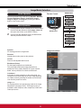
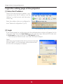
Basic Operation
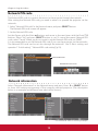
Remote Control Operation
Using the remote control for some frequently used operations is advisable. Just pressing one of the buttons
HQDEOHV\RXWRPDNHWKHGHVLUHGRSHUDWLRQTXLFNO\ZLWKRXWFDOOLQJXSWKH2Q6FUHHQ0HQX
COMPUTER 1/2, VIDEO, S-VIDEO and COMPONENT
buttons
3UHVVWKH&20387(59,'(269,'(2DQG
COMPONENT buttons on the remote control to select the
LQSXWVRXUFH6HHSDJHVIRUGHWDLOV
FREEZE button
3UHVVWKH)5((=(EXWWRQRQWKHUHPRWHFRQWUROWRIUHH]H
the picture on the screen, meanwhile, volume is muted. To
FDQFHOWKH)UHH]HIXQFWLRQSUHVVWKH)5((=(EXWWRQDJDLQ
or press any other button.
)LJZLOODSSHDURQWKH6FUHHQPHQXZKLOHWKH)UHH]H
function is working.
Fig.1
Remote Control
COMPUTER 1/2
buttons
S-VIDEO
button
VIDEO
button
FREEZE
button
D.ZOOM
buttons
COMPONENT
button
INFO.
button
LAMP
button
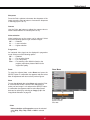
INFO. button
Display the input source information: Input, H-sync freq.,
V-sync freq., Screen, Language, Lamp status, Lamp
counter, Power management, Keylock, PIN code lock
and Remote controlS
3Note:
6HHWKHQH[WSDJHIRUWKHGHVFULSWLRQRIRWKHU
buttons.
D.ZOOM buttons
Press the D.ZOOM buttons on the remote control to enter to
WKH'LJLWDO]RRP±PRGH6HHSDJHIRUGHWDLOV
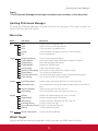
LAMP button
3UHVV WKH /$03 EXWWRQ RQ WKH UHPRWH FRQWURO WR VHOHFW WKH
lamp mode for changing the brightness on the screen.
High ........... Brighter than the Normal mode.
Normal ....... Normal brightness
Eco ............ /RZHUEULJKWQHVVUHGXFHVWKHODPSSRZHU
FRQVXPSWLRQDQGH[WHQGVWKHODPSOLIH
25
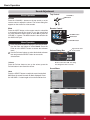
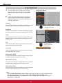
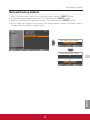
Basic Operation
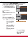
NO SHOW button
Press the NO SHOW button on the remote control to black out
the image. To restore to normal, press the NO SHOW button
again or press any other button. When the projected image is
FDSWXUHGDQGLVVHWDV8VHULQWKH/RJRVHOHFWLRQSWKH
screen changes each time you press the NO SHOW button as
follows.
EODFNRXWĺFDSWXUHGLPDJHĺQRUPDOĺ
No show GLVDSSHDUVDIWHUVHFRQGV
3Note:
When use the MUTE button to release the No Show
function, the mute function can not be operated at the same
time.
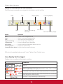
P-TIMER button
3UHVVWKH37,0(5EXWWRQRQWKHUHPRWHFRQWUROWRRSHUDWH
the Count up/Count down function. Refer to p.51 for detail of
6HWWLQJIRUWKH3WLPHUIXQFWLRQ
7RVWRSWKHFRXQWWLPHSUHVVWKH37,0(5EXWWRQ
7RFDQFHOWKH3WLPHUIXQFWLRQSUHVVDQGKROGWKH37,0(5
button.
0
37LPHUGLVSOD\
SCREEN button
IMAGE button
P-TIMER button
Press the IMAGE button on the remote control to select a
GHVLUHGLPDJHPRGHRIWKHVFUHHQ6HHSDJHVIRU
details.
NO SHOW button
IMAGE button
SCREEN button
6HOHFWWKHVFUHHQVL]H6HHSDJHVIRUGHWDLOV
3Note:
See the previous page for the description of
other buttons.
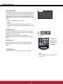
Computer Input
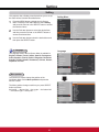
Input Source Selection (RGB: Computer 1/Computer 2)
Direct Operation
Choose either Computer 1(RGB) or Computer 2(RGB) by pressing the COMPUTER 1 or COMPUTER 2 button
on the remote control.
Before using these buttons, correct input source should be selected through Menu operation as described
below.
Remote Control
COMPUTER 1 button
Computer 1(RGB)
Computer 1(Scart)
COMPUTER 2 button
Computer 2 (RGB)
Input Menu
Menu Operation
1
3UHVVWKH0(18EXWWRQWRGLVSOD\WKH2Q6FUHHQ
Menu. Use the Point Ÿź buttons to select Input and
then press the Point ŹRUWKH6(/(&7EXWWRQ
2
Use the Point Ÿź buttons to select Computer 1.
3
When Computer 1 is selected, press the Point Ź
button to access the submenu items. Use the Point Ÿ
ź buttons to select the RGB input source and then
SUHVVWKH6(/(&7EXWWRQ
Computer
1
►
3Note:
When the Input Search function is set to On1 or On2 in
the Auto setup function, the input signal will be searched
DXWRPDWLFDOO\S
27
Computer 1
RGB
Component
RGB(Scart)
S-video
Computer Input
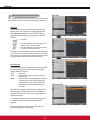
Computer System Selection
7KLVSURMHFWRUDXWRPDWLFDOO\WXQHVWRYDULRXVW\SHVRIFRPSXWHUVZLWKLWV0XOWLVFDQV\VWHPDQG$XWR3&
Adjustment. If a computer is selected as a signal source, this projector automatically detects the signal format
and tunes to project a proper image without any additional settings. (Signal formats provided in this projector are
VKRZQRQSDJH
One of the following messages may appear when:
-----
:KHQWKHSURMHFWRUFDQQRWUHFRJQL]HWKH
connected signal conforming to the provided
PC systems, Auto is displayed on the System
0HQXER[DQGWKH$XWR3&$GMXVWPHQWIXQFWLRQ
works to display proper images. If the image is
not projected properly, a manual adjustment is
UHTXLUHGSS
PC System Menu
►
Auto
There is no signal input from the computer.
Check the connection between your computer
and the projector. (See “Troubleshooting” on
S
Mode 1
The preset system is manually adjusted in the
PC adjust Menu. The adjusted data can be
stored in Mode 1–10SS
SVGA 1
PC Systems provided in this projector is chosen.
The projector chooses a proper system provided
in the projector and displays it.
Computer 1
Computer 2
Video
RGB
RGB
System
XGA 1
The PC System Menu
Selected system is
displayed.
0RGHDQG69*$DUHH[DPSOHV
&XVWRPL]HGMode
(1–10) set in the
PC adjust Menu
SS
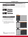
Selecting Computer System Manually
PC system can also be selected manually.
PC System Menu
1
3UHVVWKH0(18EXWWRQWRGLVSOD\WKH2Q6FUHHQ
Menu. Use the Point Ÿź buttons to select Input and
then press the Point ŹRUWKH6(/(&7EXWWRQ
2
Use the Point Ÿź buttons to select System and then
press the Point ŹRUWKH6(/(&7EXWWRQ
3
Use the Point Ÿź buttons to select the desired system
DQGWKHQSUHVVWKH6(/(&7EXWWRQ
6\VWHPVLQWKLVGLDORJER[
can be selected.
►
Computer Input
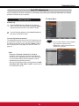
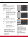
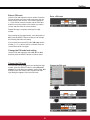
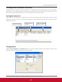
Auto PC Adjustment
Auto PC Adjustment function is provided to automatically adjust Fine sync, Total dots, Horizontal and Vertical
positions to conform to your computer.
PC adjust Menu
Menu Operation
Auto PC adj.
1
2
3UHVVWKH0(18EXWWRQWRGLVSOD\WKH2Q6FUHHQ
Menu. Use the Point Ÿź buttons to select PC adjust
and then press the Point ŹRUWKH6(/(&7EXWWRQ
►
Use the Point Ÿź buttons to select Auto PC adj. and
WKHQSUHVVWKH6(/(&7EXWWRQ
To store adjustment parameters
The adjusted parameters from the Auto PC Adjustment can
be stored in the projector. Once the parameters are stored,
the setting can be done just by selecting a Mode (1–10) in
WKH3&6\VWHP0HQXVHHSDJH6HHDOVR³6WRUH´RQ
SDJH
0
1365
0
0
0
1024
768
Use Point Ÿź buttons to select Auto PC
adj. DQGSUHVVWKH6(/(&7EXWWRQ
Please wait... appears while the Auto PC
adjustment is in process.
►
3Note:
Fine sync, Total dots, Horizontal and Vertical
position of some computers cannot be fully adjusted
with the Auto PC Adjustment function. When the image
is not provided properly with this operation, manual
DGMXVWPHQWVDUHUHTXLUHGSS
7KH$XWR3&$GMXVWPHQWFDQQRWEHRSHUDWHGZKHQ480i,
576i, 480p, 576p, 720p,1035i or 1080i is selected in the
3&6\VWHP0HQXS
Auto PC adj.
Fine sync
Total dots
Horizontal
Vertical
Current mode
Clamp
Display area H
Display area V
Reset
Mode free
Store
Auto PC adj.
Fine sync
Total dots
Horizontal
Vertical
Current mode
Clamp
Display area H
Display area V
Reset
Mode free
Store
0
1365
0
0
0
1024
768
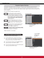
Computer Input
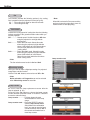
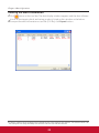
Manual PC Adjustment
6RPHFRPSXWHUVHPSOR\VSHFLDOVLJQDOIRUPDWVZKLFKPD\QRWEHWXQHGE\0XOWLVFDQV\VWHPRIWKLVSURMHFWRU
Manual PC Adjustment enables you to precisely adjust several parameters to match those signal formats. The
SURMHFWRUKDVLQGHSHQGHQWPHPRU\DUHDVWRVWRUHWKRVHSDUDPHWHUVPDQXDOO\DGMXVWHG,WDOORZV\RXWRUHFDOO
the setting for a specific computer.
1
2
3UHVVWKH0(18EXWWRQWRGLVSOD\WKH2Q6FUHHQ
Menu. Use the Point Ÿź buttons to select PC adjust
and then press the Point ŹRUWKH6(/(&7EXWWRQ
PC adjust Menu
►
Use the Point Ÿź buttons to select the desired item
DQGWKHQSUHVVWKH6(/(&7EXWWRQWRGLVSOD\WKH
DGMXVWPHQWGLDORJER[8VHWKH3RLQWŻŹ buttons to
adjust the setting value.
Auto PC adj.
Fine sync
Total dots
Horizontal
Vertical
Current mode
Clamp
Display area H
Display area V
Reset
Mode free
Store
0
1365
0
0
0
1024
768
Fine sync
Use the Point ŻŹ buttons to adjust the value, eliminating a
IOLFNHUIURPWKHLPDJHGLVSOD\HGIURPWR
Total dots
Horizontal
Use the Point ŻŹEXWWRQVWRDGMXVWWKHKRUL]RQWDOSLFWXUH
position.
Vertical
Use the Point ŻŹ buttons to adjust the vertical picture
position.
Current mode
3UHVVWKH6(/(&7EXWWRQWRVKRZH-sync freq. and V-sync
freq. of the connected computer.
Clamp
Use the Point ŻŹ buttons to adjust the clamp level. When
the image has dark bars, try this adjustment.
Display area H
Use the Point ŻŹ EXWWRQV WR DGMXVW WKH KRUL]RQWDO DUHD
displayed by this projector.
Display area V
Use the Point ŻŹ buttons to adjust the vertical area
displayed by this projector.
►
Use the Point ŻŹ buttons to adjust the number of total dots
LQRQHKRUL]RQWDOSHULRGWRPDWFK\RXU3&LPDJH
Auto PC adj.
Fine sync
Total dots
Horizontal
Vertical
Current mode
Clamp
Display area H
Display area V
Reset
Mode free
Store
0
1365
0
0
0
1024
768
Computer Input
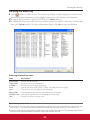
Reset
Mode free
►
To reset the adjusted data, select Reset and press the
6(/(&7EXWWRQ$FRQILUPDWLRQER[DSSHDUVDQGWKHQVHOHFW
Yes. All adjustments will return to their previous figures.
Mode free
To clear the stored data, select Mode free and then press
the Point ŹRUWKH6(/(&7EXWWRQ0RYHWKHKLJKOLJKWWRWKH
0RGHWKDW\RXZDQWWRFOHDUDQGWKHQSUHVVWKH6(/(&7
button.
Auto PC adj.
Fine sync
Total dots
Horiznotal
Vertical
Current mode
Clamp
Display area H
Display area V
Reset
Mode free
Store
0
1365
0
0
0
1024
768
►
This Mode has stored
parameters.
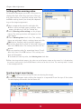
Store
To store the adjusted data, select Store and then press the
Point ŹRUWKH6(/(&7EXWWRQ. Move the highlight to one
RIWKH0RGHVWRLQZKLFK\RXZDQWWRVWRUHDQGWKHQ
SUHVVWKH6(/(&7EXWWRQ
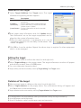
Where to free?
Mode 1
Mode 2
Mode 3
Mode 4
Mode 5
Mode 6
Mode 7
Mode 8
Mode 9
Mode 10
Total dots
Horizontal
Vertical
Display area H
Display area V
1344
0
255
34
0
1024
768
►
Values of Total dots, Horizontal,
Vertical, Display area H, and
Display area V.
Vacant
Store
Store
►
Press MENU button
to close this dialog
ER[
Mode 1
Mode 2
Mode 3
Mode 4
Mode 5
Mode 6
Mode 7
Mode 8
Mode 9
Mode 10
Where to store?
store?
Free
Total
Total dots
dots
Position
H
Horizontal
Position
Vertical V
Display
Display area H
Display
Display area V
1344
00
255
0
0
34
1024
768
3UHVV6(/(&7EXWWRQWR
store the data.
3Note:
Display area (H/V) cannot be selected when 480i, 576i, 480p, 576p, 720p, 1035i or 1080i is selected in the
3&6\VWHP0HQXS
When input computer signal to the projector, PC adjust will become available.
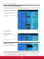
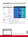
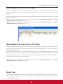
Computer Input
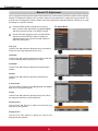
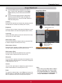
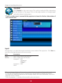
Image Mode Selection
Direct Operation
Remote Control
Select the desired image mode among Dynamic, Standard,
Real, Blackboard (Green), Colorboard, Image 1, Image 2,
Image 3 and Image 4 by pressing the IMAGE button on the
remote control.
IMAGE button
Dynamic
Standard
Real
Blackboard(Green)
IMAGE button
Colorboard
Image 1
Image 2
Menu Operation
1
2
Image 3
3UHVVWKH0(18EXWWRQWRGLVSOD\WKH2Q6FUHHQ0HQX
Use the Point Ÿź buttons to select Image select and
then press the Point ŹRUWKH6(/(&7EXWWRQ
Image 4
Use the Point Ÿź buttons to select the desired item
DQGWKHQSUHVVWKH6(/(&7EXWWRQ
Dynamic
For viewing pictures in a bright room.
Image select Menu
Standard
Normal picture mode preset on the projector.
Real
Picture mode with improved halftone for graphics.
Blackboard (Green)
For the image projected on a blackboard.
This mode helps enhance the image projected on a
blackboard. This is mainly effective on a green colored
board, not truly effective on a black colored board.
Image 1–4
For viewing with the user preset image mode in the Image
$GMXVW0HQXVHHSDJHV7KLV,PDJHPHPRU\LV
SURYLGHGLQHDFKFRPSXWHUFRPSRQHQW6YLGHRDQGYLGHR
input source.
►
Colorboard
At the time of simple projection on the colored wall, you
can get the close color image to the color image projected
on a white screen by selecting the similar color to the wall
color from the preset four colors.
Dynamic
Standard
Real
Blackboard(Green)
Colorboard
Image 1
Image 2
Image 3
Image 4
Red
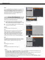
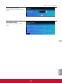
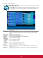
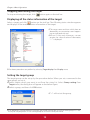
Computer Input
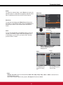
Image Adjustment
1
3UHVVWKH0(18EXWWRQWRGLVSOD\WKH2Q6FUHHQ
Menu. Use the Point Ÿź buttons to select Image
adjust and then press the Point ŹRUWKH6(/(&7
button.
2
Use the Point Ÿź buttons select the desired item
DQGWKHQSUHVVWKH6(/(&7EXWWRQWRGLVSOD\WKH
DGMXVWPHQWGLDORJER[8VHWKH3RLQWŻŹ buttons to
adjust the setting value.
Image Adjust Menu
Contrast
Press the Point Ż button to decrease the contrast; press the
Point ŹEXWWRQWRLQFUHDVHWKHFRQWUDVWIURPWR
Brightness
Selected Image mode
Press the Point Ż button to decrease the brightness; press
the Point ŹEXWWRQWRLQFUHDVHWKHEULJKWQHVVIURPWR
Color temp.
Use the Point ŻŹ buttons to select the desired Color temp.
OHYHO;/RZ/RZ0LGRU+LJK
White balance (Red)
Press the PointŻ button to lighten red tone; press the Point
ŹEXWWRQWRGHHSHQUHGWRQHIURPWR
Use the Point ŻŹ
buttons to adjust the
setting value.
White balance (Green)
Press the Point Ż button to lighten green tone; press the
Point ŹEXWWRQWRGHHSHQJUHHQWRQHIURPWR
White balance (Blue)
Press the Point Ż button to lighten blue tone; press the
Point ŹEXWWRQWRGHHSHQEOXHWRQHIURPWR
Sharpness
Press the Point Ż button to decrease the sharpness of the
image; press the Point Ź button to increase the sharpness
RIWKHLPDJHIURPWR
Gamma
Use the Point ŻŹ buttons to adjust the gamma value to
REWDLQDEHWWHUEDODQFHRIFRQWUDVWIURPWR
Reset
To reset the adjusted data, select Reset and press the
6(/(&7EXWWRQ$FRQILUPDWLRQER[DSSHDUVDQGWKHQVHOHFW
Yes. All adjustments will return to their previous figures.
3Note:
:KHQ:KLWHEDODQFH Red, Green or Blue is
adjusted, Color temp. will change to User.
:KHQBlackboard(Green) or Colorboard
is selected in Image select, Color temp. will
change to Blackboard or Colorboard.
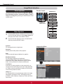
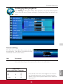
Computer Input
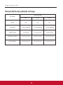
Where to store?
Store
►
To store the adjusted data, select Store and press the Point
ŹRUWKH6(/(&7EXWWRQ8VHWKH3RLQWŸź buttons to
select one from Image 1 to 4DQGSUHVVWKH6(/(&7EXWWRQ
$FRQILUPDWLRQER[DSSHDUVDQGWKHQVHOHFWYes. Stored
data can be called up by selecting an Image (1–4) in the
,PDJH0RGH6HOHFWLRQRQSDJH
Image 1
Image 2
Image 3
Image 4
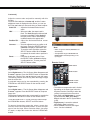
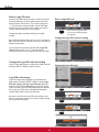
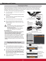
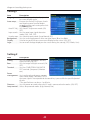
Screen Size Adjustment
7KLVSURMHFWRUKDVWKHSLFWXUHVFUHHQUHVL]HIXQFWLRQZKLFK
HQDEOHV\RXWRFXVWRPL]HWKHLPDJHVL]H
1
3UHVVWKH0(18EXWWRQWRGLVSOD\WKH2Q6FUHHQ
Menu. Use the Point Ÿź buttons to select Screen and
then press the Point ŹRUWKH6(/(&7 button.
2
Use the Point Ÿźbuttons select the desired item and
WKHQSUHVVWKH6(/(&7EXWWRQ
$FRQILUPDWLRQER[DSSHDUVDQG
then select Yes.
Screen Menu
Normal
3URYLGHWKHLPDJHWRILWWKHVFUHHQVL]H
True
3URYLGHWKHLPDJHLQLWVRULJLQDOVL]H:KHQWKHRULJLQDO
LPDJHVL]HLVODUJHURUVPDOOHUWKDQWKHVFUHHQVL]H
[WKHSURMHFWRUHQWHUVWRWKHSDQQLQJPRGH
automatically. Use the Point ŸźŻŹbuttons to pan the
image. When adjusted, the arrows will turn red. When
reached to the correction limits, the arrows will disappear.
►
Wide
3URYLGHWKHLPDJHWRILWWKHZLGHYLGHRDVSHFWUDWLRE\
H[SDQGLQJWKHLPDJHZLGWKXQLIRUPO\7KLVIXQFWLRQFDQEH
XVHGIRUSURYLGLQJDVTXHH]HGYLGHRVLJQDODW
Normal
True
Wide
Full
Custom
Custom adj.
Digital zoom +
Digital zoom -
Normal
True
Full
Wide
Custom
Custom adj.
Digital zoom +
Digital zoom -
►
Full
Provide the full screen image.
Custom
Provide the last stored aspect screen image.
3Note:
7KH6FUHHQ0HQXonly Normal and Custom can be operated, Wide will be disabled and displayed in gray
when 720p, 1035i, or 1080iLVVHOHFWHGLQWKH3&6\VWHP0HQXS
7KLVSURMHFWRUFDQQRWGLVSOD\DQ\UHVROXWLRQKLJKHUWKDQ[,I\RXUFRPSXWHU¶VVFUHHQUHVROXWLRQLV
higher than it, reset the resolution to the lower before connecting to the projector.
7KHLPDJHGDWDLQRWKHUWKDQ[LVPRGLILHGWRILWWKHVFUHHQVL]HLQLQLWLDOPRGH
True, Full, and Digital zoom +/– are disabled and cannot be displayed when 480i, 576i, 480p or 576p is
VHOHFWHGLQWKH3&6\VWHP0HQXS
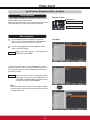
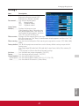
Computer Input
Custom adj.
Adjust the screen scale and position manually with this
function.
Press the Point Źbutton at Custom adj. and the Custom
adjustment menu is displayed on the screen, you can use
the Point Ÿź buttons to choose the item you want to adjust.
►
Scale H/V .......... $GMXVWWKH+RUL]RQWDO9HUWLFDOVFUHHQ
scale.
H&V ................... When set to On, the aspect ratio is
IL[HG7KHScale V appears dimmed and
becomes unavailable. Adjust Scale H,
then the screen scale is automatically
modified based on the aspect ratio.
Position H/V ..... $GMXVW WKH +RUL]RQWDO9HUWLFDO VFUHHQ
position.
Common ........... Save the adjusted scale or position to all
WKHLQSXWV3UHVVWKH6(/(&7EXWWRQDW
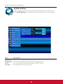
CommonWRGLVSOD\DFRQILUPDWLRQER[
To save the scale or position, press the
6(/(&7EXWWRQDWYes. When Custom
is selected, the saved scale or position is
used.
Reset ................. Reset the all adjusted values. Press
WKH6(/(&7EXWWRQDWReset to display
DFRQILUPDWLRQER[7RUHVHWSUHVVWKH
6(/(&7EXWWRQDWYes.
adj.
3Note:
:KHQQRVLJQDOLVGHWHFWHGNormal is set
automatically .
7KHDGMXVWDEOHUDQJHIRUScale H/V and
Position H/V is limited depending on the
input signal.
Remote Control
POINT buttons
For zooming in and out the images
Digital zoom +
Select Digital zoom +7KH2Q6FUHHQ0HQXGLVDSSHDUVDQG
D. zoom +DSSHDUV3UHVVWKH6(/(&7EXWWRQWRH[SDQGWKH
LPDJHVL]H8VHWKH3RLQWŸźŻŹ buttons to pan the image.
The Panning function can work only when the image is larger
WKDQWKHVFUHHQVL]H
$ SURMHFWHG LPDJH FDQ EH DOVR H[SDQGHG E\ SUHVVLQJ WKH
D.ZOOM ŸRUWKH6(/(&7EXWWRQRQWKHUHPRWHFRQWURO
Digital zoom –
Select Digital zoom –7KH2Q6FUHHQ0HQXGLVDSSHDUVDQG
D. zoom –DSSHDUV3UHVVWKH6(/(&7EXWWRQWRFRPSUHVV
LPDJHVL]H
The projected image can be also compressed by pressing the
D.ZOOM ź RUWKH6(/(&7 button on the remote control.
7RH[LWWKH'LJLWDO]RRP±PRGHSUHVVDQ\EXWWRQH[FHSW
the D.ZOOM ŸźEXWWRQV6(/(&7DQG3RLQWEXWWRQV
7R UHWXUQ WR WKH SUHYLRXV VFUHHQ VL]H VHOHFW D VFUHHQ VL]H
IURP WKH 6FUHHQ 6L]H$GMXVWPHQW 0HQX RU VHOHFW DQ LQSXW
source from the Input Source Selection Menu (see page
DJDLQ RU DGMXVW WKH VFUHHQ VL]H ZLWK WKH '=220 Ÿź
buttons.
SELECT button
D.ZOOM + button
D.ZOOM - button
3Note:
7KHPLQLPXPFRPSUHVVLRQUDWLRLVOLPLWHG
depending on the input signal, when the
Keystone function is working or when the
FXVWRPLVVHOHFWHGIRUWKHVFUHHQVL]H
True, Full, and Digital zoom +/– cannot
be selected when 480i, 576i, 480p or
576p is selected in the PC System Menu
S
Digital zoom +/- cannot be selected
when Full or True is selected.
:KHQCustom is selected, the Digital
]RRPIXQFWLRQLVGLVDEOHG
Video Input
Input Source Selection (Video, S-video)
Direct Operation
Choose Video or S-videoE\SUHVVLQJWKH9,'(2RUWKH6
VIDEO button on the remote control.
Before using these buttons, correct input source should be
selected through menu operation as described below.
Remote Control
VIDEO button
Video
S-VIDEO button
S-video
Menu Operation
1
3UHVVWKH0(18EXWWRQWRGLVSOD\WKH2Q6FUHHQ
Menu. Use the Point Ÿź buttons to select Input and
then press the Point Źor WKH6(/(&7EXWWRQ
2
Use the Point Ÿźbuttons to select Video and then
SUHVVWKH6(/(&7EXWWRQ
Video
Input Menu
When video input signal is connected to the
VIDEO jack, select Video.
Auto
Use the Point Ÿźbuttons to select Computer 1. And then
press the Point Źbutton to access the submenu items. Use
the Point Ÿź buttons to select the S-video and then press
WKH6(/(&7EXWWRQ
S-video
When the input source is coming from video
equipment connected to the COMPUTER IN
69,'(2 ,1&20321(17 ,1 WHUPLQDO ZLWK D
6YLGHR9*$FDEOHVHOHFWS-VIDEO.
Auto
3Note:
When the Input Search function is set to On1 or On2 in
the Auto setup function, the input signal will be searched
DXWRPDWLFDOO\S
Computer
1
Video Input
Input Source Selection (Component, RGB Scart 21-pin)
Direct Operation
Choose Computer 1(Component) or Computer 1(Scart) by pressing the COMPONENT or the COMPUTER 1
button on the remote control.
Before using these buttons, correct input source should be selected through Menu operation as described
below.
Remote Control
COMPUTER 1 button
Computer 1(RGB)
Computer 1(Scart)
COMPONENT button
Computer 1(Component)
Input Menu
Menu Operation
1
3UHVVWKH0(18EXWWRQWRGLVSOD\WKH2Q6FUHHQ
Menu. Use the Point Ÿź buttons to select Input and
then press the Point ŹRUWKH6(/(&7EXWWRQ
2
Use the Point Ÿź buttons to select Computer 1 and
then press the Point Ź button.
3
Use the Point Ÿź buttons to select Component or
RGB(Scart) and then SUHVVWKH6(/(&7EXWWRQ
Component
When the input source is coming from video
equipment connected to the COMPUTER
,169,'(2,1&20321(17,1WHUPLQDO
ZLWKD&RPSRQHQW9*$&DEOHVHOHFW
Component.
RGB (Scart)
When the input source is coming from video
equipment connected to the COMPUTER
,169,'(2,1&20321(17,1WHUPLQDO
ZLWKD6FDUW9*$&DEOHVHOHFWRGB
(Scart).
S-video
3Note:
When the Input Search function is set to On1 or On2,
WKHLQSXWVLJQDOZLOOEHVHDUFKHGDXWRPDWLFDOO\S
Video Input
Video System Selection
1
3UHVVWKH0(18EXWWRQWRGLVSOD\WKH2Q6FUHHQ
Menu. Use the Point Ÿź buttons to select Input and
then press the Point ŹRUWKH6(/(&7EXWWRQ
2
Select Video, S-video or Computer 1(Component)
LQSXWVRXUFH6HHSDJHV
3
Use the Point Ÿź buttons to select System and then
press the Point Ź RUWKH6(/(&7EXWWRQ8VHWKH3RLQW
Ÿźbuttons to select the desired system and then
SUHVVWKH6(/(&7EXWWRQ
AV System Menu (Video or S-video)
Video or S-video
Auto
The projector automatically detects an incoming video
V\VWHP DQG DGMXVWV LWVHOI WR RSWLPL]H LWV SHUIRUPDQFH
When Video System is PAL-M or PAL-N, select the system
manually.
PAL/SECAM/NTSC/NTSC4.43/PAL-M/PAL-N
If the projector cannot reproduce proper video image,
select a specific broadcast signal format from among PAL,
SECAM, NTSC, NTSC 4.43, PAL-M, and PAL-N.
Component
Auto
The projector automatically detects an incoming video
VLJQDODQGDGMXVWVLWVHOIWRRSWLPL]HLWVSHUIRUPDQFH
COMPONENT VIDEO SIGNAL FORMAT
If the projector cannot reproduce proper video image, select
a specific component video signal format from among 480i,
576i, 480p, 576p, 720p, 1035i, and 1080i.
3Note:
The AV System Menu cannot be selected when selecting
RGB (Scart).
AV System Menu (Component)
Video Input
Image Mode Selection
Remote Control
Direct Operation
IMAGE button
Dynamic
Select the desired image mode among Dynamic, Standard,
Cinema, Blackboard (Green), Colorboard, Image 1,
Image 2, Image 3 and Image 4 by pressing the IMAGE
button on the remote control.
Standard
Cinema
Menu Operation
1
2
Blackboard (Green)
3UHVVWKH0(18EXWWRQWRGLVSOD\WKH2Q6FUHHQ0HQX
Use the Point Ÿź buttons to select Image select and
then press the Point ŹRUWKH6(/(&7EXWWRQ
IMAGE button
Use the Point Ÿź buttons to select the desired item
DQGWKHQSUHVVWKH6(/(&7EXWWRQ
Colorboard
Image 1
Image 2
Image 3
Image 4
Dynamic
For viewing pictures in a bright room.
Image select Menu
Standard
Normal picture mode preset on the projector.
Cinema
Picture mode adjusted with fine tone.
Blackboard (Green)
For the image projected on a blackboard.
This mode help enhance the image projected on a
blackboard. This is mainly effective on a green colored
board, not truly effective on a black colored board.
Image 1–4
For viewing with the user preset image mode in the Image
$GMXVW0HQXVHHSDJHV7KLV,PDJHPHPRU\LV
SURYLGHGLQHDFKFRPSXWHUVFDUWFRPSRQHQW6YLGHRDQG
video input source.
►
Colorboard
At the time of simple projection on the colored wall, you
can get the close color image to the color image projected
on a white screen by selecting the similar color to the wall
color from the preset four colors.
Video Input
Image Adjustment
1
3UHVVWKH0(18EXWWRQWRGLVSOD\WKH2Q6FUHHQ
Menu. Use the Point Ÿź buttons to select Image
adjust and then press the Point Źor the6(/(&7
button.
2
Use the Point Ÿź buttons select the desired item
DQGWKHQSUHVVWKH6(/(&7EXWWRQWRGLVSOD\WKH
DGMXVWPHQWGLDORJER[8VHWKH3RLQWŻŹ buttons to
adjust the setting value.
Image Adjust Menu
Contrast
Press the Point Ż button to decrease the contrast; press the
Point ŹEXWWRQWRLQFUHDVHWKHFRQWUDVWIURPWR
Selected Image mode
Brightness
Press the Point Ż button to decrease the brightness; press
the Point ŹEXWWRQWRLQFUHDVHWKHEULJKWQHVVIURPWR
Color
Press the Point Ż button decrease the intensity of the color;
press the Point Źbutton increase the intensity of the color
IURPWR
Tint
Press the Point ŻŹbuttons to adjust the tint value to get a
SURSHUFRORUEDODQFHIURPWR
Use the Point ŻŹ
buttons to adjust the
setting value.
Color temp.
Use the Point ŻŹ buttons to select the desired Color temp.
OHYHO+LJK0LG/RZRU;/RZ
White balance (Red)
Press the Point Żbutton to lighten red tone; press the Point
ŹEXWWRQWRGHHSHQUHGWRQHIURPWR
White balance (Green)
Press the Point Ż button to lighten green tone; press the
Point ŹEXWWRQWRGHHSHQJUHHQWRQHIURPWR
White balance (Blue)
Press the Point Ż button to lighten blue tone; press the
Point ŹEXWWRQWRGHHSHQEOXHWRQHIURPWR
3Note:
:KHQWKHWhite balance Red, Green or Blue is adjusted, the Color temp. level will change to User.
7LQWFDQQRWEHVHOHFWHGZKHQWKHYLGHRV\VWHPLVPAL, SECAM, PAL-M or PAL-NS
:KHQBlackboard(Green) or Colorboard is selected in Image select, Color temp. will change to
Blackboard or Colorboard.
Video Input
Sharpness
Press the Point Ż button to decrease the sharpness of the
image; press the Point Ź button to increase the sharpness
RIWKHLPDJHIURPWR
Gamma
Use the Point ŻŹ buttons to adjust the gamma value to
REWDLQDEHWWHUEDODQFHRIFRQWUDVWIURPWR
Noise reduction
Noise interference on the screen can be reduced. Select
one of the following options to get smoother images.
Off ......... Disabled.
L1 ........../RZHUUHGXFWLRQ
L2 .......... Higher reduction
Progressive
An interlaced video signal can be displayed in progressive
mode. Select one of the following options.
Off ......... Disabled.
L1 .......... For an active picture.
L2 .......... For a still picture.
Film ....... For watching a film. With this function, the
projector reproduces pictures faithful to the
original film quality.
Store Menu
Reset
To reset the adjusted data, select Reset and press the
6(/(&7EXWWRQ$FRQILUPDWLRQER[DSSHDUVDQGWKHQVHOHFW
Yes. All adjustments will return to their previous figures.
Store
To store the adjusted data, select Store and press the Point
ŹRUWKH6(/(&7EXWWRQ8VHWKH3RLQWŸź buttons to
VHOHFWRQHIURP,PDJHWRDQGSUHVVWKH6(/(&7EXWWRQ
$FRQILUPDWLRQER[DSSHDUVDQGWKHQVHOHFWYes. Stored
data can be called up by selecting an Image (1–4) in the
,PDJH0RGH6HOHFWLRQRQSDJH
$FRQILUPDWLRQER[
appears and then
select Yes.
3Note:
Noise reduction and Progressive cannot be selected
when 480p, 576p, 720p, 1035i or 1080i is selected
S
Video Input
Screen Size Adjustment
7KLVSURMHFWRUKDVWKHSLFWXUHVFUHHQUHVL]HIXQFWLRQZKLFKHQDEOHV\RXWRFXVWRPL]HWKHLPDJHVL]H
1
3UHVVWKH0(18EXWWRQWRGLVSOD\WKH2Q6FUHHQ
Menu. Use the Point Ÿź buttons to select Screen and
then press the Point ŹRUWKH6(/(&7EXWWRQ
2
Use the Point Ÿź buttons select the desired item and
WKHQSUHVVWKH6(/(&7EXWWRQ
Screen Menu
►
►
Normal
3URYLGHWKHLPDJHWRILWWKHVFUHHQVL]HZKLOHPDLQWDLQLQJ
the aspect ratio of the input signal.
Wide
0RGLI\WKHDVSHFWUDWLRLPDJHWRILWWKHVFUHHQVL]H
aspect ratio) by streching the image.
Custom
Provide the last stored aspect screen image.
Custom adj.
Scale H/V .......... $GMXVWWKH+RUL]RQWDO9HUWLFDOVFUHHQ
scale.
H&V ................... When set to On, the aspect ratio is
IL[HG7KHScale V appears dimmed and
becomes unavailable. Adjust Scale H,
then the screen scale is automatically
modified based on the aspect ratio.
Position H/V ..... $GMXVW WKH +RUL]RQWDO9HUWLFDO VFUHHQ
position.
Common ........... Save the adjusted scale or position to all
WKHLQSXWV3UHVVWKH6(/(&7EXWWRQDW
CommonWRGLVSOD\DFRQILUPDWLRQER[
To save the scale or position, press the
6(/(&7EXWWRQDWYes. When Custom
is selected, the saved scale or position is
used.
Reset ................. Reset the all adjusted values. Press
WKH6(/(&7EXWWRQDWReset to display
DFRQILUPDWLRQER[7RUHVHWSUHVVWKH
6(/(&7EXWWRQDWYes.
►
Adjust the screen scale and position manually with this
function.
Press the Point Źbutton at Custom adj. and the Custom
adjustment menu is displayed on the screen, you can use
the Point Ÿź buttons to choose the item you want to adjust.
3Note:
:KHQQRVLJQDOLVGHWHFWHGNormal is set
automatically.
7KHDGMXVWDEOHUDQJHIRUScale H/V and
Position H/V is limited depending on the
input signal.
Wide cannot be operated when 720p,
1035i or 1080i is selected in the AV
6\VWHP0HQXS
Setting
Setting
This projector has a Setting menu that allows you to set up
the other various functions described below.
1
3UHVVWKH0(18EXWWRQWRGLVSOD\WKH2Q6FUHHQ
Menu. Press the Point Ÿź buttons to select Setting
and press the Point ŹRUWKH6(/(&7EXWWRQWRDFFHVV
the submenu items.
2
Use the Point Ÿź buttons to select the desired item
and then press the Point ŹRUWKH6(/(&7EXWWRQWR
access the selected item.
3
Setting Menu
Standby mode
Use the Point Ÿź buttons select the desired item and
WKHQSUHVVWKH6(/(&7EXWWRQ
Language
Language
7KHODQJXDJHXVHGLQWKH2Q6FUHHQ0HQXLVDYDLODEOHLQ
English, German, French, Italian, Spanish, Portuguese,
Dutch, Swedish, Finnish, Polish, Hungarian, Romanian,
Russian,Turkish, Kazakh, Vietnamese, Chinese, Korean,
Japanese and Thai.
Language
English
Standby mode
Menu position
This function is used to change the position of the
2Q6FUHHQ0HQX6HOHFWMenu position and press the
6(/(&7EXWWRQ
7KH0HQXSRVLWLRQFKDQJHVHDFKWLPH\RXSUHVV6(/(&7
button as follows.
the top left ĺ the top right ĺ the center ĺ the bottom left
ĺ the bottom right ĺ the top left ĺ.....
►
1/2
Setting
Auto setup
Auto setup
English
This function enables Input search, Auto Keystone correction
and Auto PC adjustment by pressing the AUTO SETUP button
on the top control or the AUTO SET button on the remote
control. Settings for those functions can be altered as follows:
Input search
This function detects the input signal automatically. When
a signal is found, the search will stop. Use the Point Ÿź
buttons to select one of the following options.
Off ........... Input search does not work.
On1.......... Input search works under the following situation.
±:KHQSUHVVLQJWKHAUTO SETUP button on
the top control.
±:KHQ SUHVVLQJ WKHAUTO SET button on the
remote control.
On2.......... Input search works under the following situation.
±:KHQWXUQLQJRQWKHSURMHFWRUE\SUHVVLQJWKH
2167$1'%<EXWWRQRQWKHWRSFRQWURORUWKH
remote control.
±:KHQ SUHVVLQJ WKHAUTO SET button on the
remote control.
±:KHQ SUHVVLQJ WKH AUTO SETUP button on
the top control.
±:KHQWKHFXUUHQWLQSXWVLJQDOLVFXWRII
,IWKH1RVKRZRU)UHH]HIXQFWLRQLVDFWLYHFDQFHOLWWR
DFWLYDWHWKH,QSXWVHDUFK,WLVDOVRXQDYDLODEOHZKHQ2Q
Screen menu is displayed.
►
Blue
On
Off
Off
Computer 2
►
Direct on
Standby mode
Off
Off
Network
1/2
On 1
On
Auto PC adj.
Auto
Auto Keystone
►
On 1
On
Auto
Auto PC adj.
On............ Enables Auto PC Adjustment when pressing
the AUTO SET button on the remote control or
the AUTO SETUP button on the top control.
Off.............. Disables Auto PC Adjustment.
►
Auto Keystone
Auto........... Always works and corrects keystone distortion
DFFRUGLQJWRWKHSURMHFWRU
VWLOW
Manual....... Works only when pressing the AUTO SETUP
button on the top control or the AUTO SET
button on the remote control.
Off.............. Disables Auto Keystone.
3Note:
:KLOHInput search is set to On1 or On2, the status of Input
DQG/DPSDUHGLVSOD\HGHYHU\WLPHWKHVLJQDOLVVZLWFKHG
2QO\WKHODVWVHOHFWHGLQSXWVRXUFHFDQEHGHWHFWHG
'XULQJInput search is in progress, If the MENU button or the
2167$1'%<EXWWRQLVSUHVVHGInput search will stop. If
the COMPUTER 1/2 button or9,'(2RU&20321(17RU6
VIDEO button is pressed, Input search will stop and go back
WRWKHEXWWRQ
VLQSXWVLJQDO
Input search, Auto PC adj. and Auto Keystone cannot be
set Off at the same time.
3Note:
Auto Keystone corrects vertical distortion only,
QRWFRUUHFWKRUL]RQWDOGLVWRUWLRQ
7KH$XWR.H\VWRQHIXQFWLRQFDQQRWZRUNZKHQ
the Ceiling feature is set On in the Setting menu
S
3HUIHFWFRUUHFWLRQRIWKHLPDJHGLVWRUWLRQFDQQRW
be ensured with the Auto setup function. If the
distortion is not corrected properly by pressing the
AUTO SETUP or the AUTO SET button, adjust
manually by pressing the KEYSTONE button on
the remote control or selecting Keystone in the
6HWWLQJPHQXSS
Fine sync, Total dots, Horizontal and Vertical
position of some computers cannot be fully
adjusted with the Auto PC Adjustment function.
When the image is not provided properly with
this operation, manual adjustments are required
SS
Setting
Keystone
Keystone
English
Blue
On
Off
Computer 2
Direct on
Standby mode
Off
Off
Network
1/2
Background
Keystone
Store
Select the background screen for when no input signal is
detected. Press the Point Ÿź buttons to switch between
each option.
Display
7KLVIXQFWLRQGHFLGHVZKHWKHUWRGLVSOD\2Q6FUHHQ'LVSOD\V
On ........................... 6KRZ DOO WKH 2Q6FUHHQ GLVSOD\V
Use this function when you want
to project images after the lamp
becomes bright enough. The factory
default setting is in this option.
Off ........................... +LGHWKH2Q6FUHHQ'LVSOD\VH[FHSW
Ɣ2Q6FUHHQ0HQX
Ɣ Power off?S
Ɣ37LPHUGLVSOD\S
Ɣ No signal for Power management
S
Ɣ Please wait ...
Ɣ Arrows for the True function in the
6FUHHQ0HQXS
►
Blue . . . Project a blue background.
User . . . 3URMHFWDQLPDJHFDSWXUHGLQWKH/RJRVHWWLQJ
Black . . Project a black background.
►
Off
►
This function is used to adjust keystone distortion of the
projected image. Use the Point Ÿź buttons to choose the
item you want to adjust.
Keystone
7RFRUUHFWNH\VWRQHGLVWRUWLRQSUHVVWKH6(/(&7EXWWRQ
KeystoneDSSHDUVRQWKHVFUHHQ8VHWKH3RLQWŸź
EXWWRQVWRFRUUHFWNH\VWRQHGLVWRUWLRQS
Store
Store ..... Keep the keystone correction even when the AC
power cord is unplugged.
Reset ..... Release the keystone correction when the AC
power cord is unplugged.
Store
Setting
Logo (Logo and Logo PIN code lock settings)
3Note:
When OnLVVHOHFWHGLQWKH/RJR3,1FRGHORFNIXQFWLRQ
Logo select and Capture functions cannot be selected.
Logo select
English
Store
Blue
On
►
Off
Off
Computer 2
►
7KLVIXQFWLRQDOORZV\RXWRFXVWRPL]HWKHVFUHHQORJRZLWK
Logo select, capture, Logo PIN code lock and Logo PIN
code change functions.
Direct on
Standby mode
Off
Off
Network
1/2
Logo select
7KLVIXQFWLRQGHFLGHVRQWKHVWDUWLQJXSGLVSOD\IURP
among following options.
User ........ Show the image you captured.
Default .... 6KRZWKHIDFWRU\VHWORJR
Off ........... Nothing is shown on the screen.
Default
Off
Off
►
Default
Setting
Capture
This function enables you to capture an image being
SURMHFWHGWRXVHLWIRUDVWDUWLQJXSGLVSOD\RULQWHUYDORI
presentations.
Capture
Off
Off
Select CaptureDQGSUHVVWKH6(/(&7EXWWRQ
$FRQILUPDWLRQER[DSSHDUVDQGVHOHFWYes to capture the
projected image.
►
$IWHU FDSWXULQJ WKH SURMHFWHG LPDJH JR WR WKH /RJR VHOHFW
function and set it to User. Then the captured image will be
GLVSOD\HG WKH QH[W WLPH \RX WXUQ RQ WKH SURMHFWRU RU ZKHQ
\RXSUHVVWKH126+2:EXWWRQVHHSDJH
Move
Start
To cancel the capture function, select Yes in the "Quit?"
FRQILUPDWLRQER[
3Note:
%HIRUH FDSWXULQJ DQ LPDJH VHOHFW Standard in the
,PDJH VHOHFW 0HQX WR FDSWXUH D SURSHU LPDJH SS
$ VLJQDO IURP D FRPSXWHU FDQ EH FDSWXUHG XS WR ;*$
[ $ VLJQDO IURP YLGHR HTXLSPHQW FDQ EH
FDSWXUHGH[FHSWIRUSLDQGL
:KHQ FDSWXULQJ WKH LPDJH WKDW KDV EHHQ DGMXVWHG E\
the Keystone function, the adjusted data is automatically
reset and the projector captures an image without
keystone correction.
:KHQLogo PIN code lock is set to On, capture cannot
be selected.
:KHQ VWDUWLQJ WR FDSWXUH D QHZ LPDJH WKH SUHYLRXVO\
stored image is cleared even if you cancel the capturing.
:KHQ WKHUH LV QR FDSWXUHG LPDJH RU LW LV LQWHUUXSWHG
while capturing an image, User cannot be selected, you
can only switch between Default and Off.
Logo PIN code lock
Logo PIN code lock
7KLVIXQFWLRQSUHYHQWVDQXQDXWKRUL]HGSHUVRQIURP
changing the screen logo.
Off
Off
If you want to change the Logo PIN code lock setting,
SUHVVWKH6(/(&7EXWWRQDQGWKH/RJR3,1FRGHGLDORJ
ER[DSSHDUV(QWHUD/RJR3,1FRGHE\IROORZLQJWKHVWHSV
below. The initial Logo PIN codeLVVHWWR³´DWWKH
factory.
►
Off ........... The screen logo can be changed freely from
WKH/RJR0HQXS
On ........... The screen logo cannot be changed without a
/RJR3,1FRGH
Setting
Enter a Logo PIN code
Use the Point Ÿź buttons to enter a number. Press the
Point ŻŹEXWWRQVWRIL[WKHQXPEHUDQGPRYHWKHUHG
IUDPHSRLQWHUWRWKHQH[WER[7KHQXPEHUFKDQJHVWR
¼,I\RXIL[HGDQLQFRUUHFWQXPEHUXVHWKH3RLQWŻŹ
buttons to move the pointer to the number you want to
correct, and then enter the correct number.
Enter a Logo PIN code
Logo PIN code
$IWHUDFRUUHFW/RJR3,1FRGH
is entered, the following dialog
ER[DSSHDUV
5HSHDWWKLVVWHSWRFRPSOHWHHQWHULQJDIRXUGLJLW
number.
Change the Logo PIN code lock setting
$IWHUHQWHULQJWKHIRXUGLJLWQXPEHUPRYHWKHSRLQWHUWR
Set 3UHVV WKH 6(/(&7 EXWWRQ VR WKDW \RX FDQ VWDUW WR
operate the projector.
Off
,I\RXHQWHUHGDQLQFRUUHFW/RJR3,1FRGHLogo PIN
code and the number (¼¼¼¼) will turn red for a
PRPHQW(QWHUWKHFRUUHFW/RJR3,1FRGHDOORYHUDJDLQ
►
Select
Change the Logo PIN code lock setting
Use the Point Ÿźbuttons to switch On or Off, and then
SUHVVWKH6(/(&7EXWWRQWRPDNHDFKLRFH
Change the Logo PIN code
Off
Logo PIN code change
►
/RJR3,1FRGHFDQEHFKDQJHGWR\RXUGHVLUHGIRXU
GLJLWQXPEHU3UHVVWKH6(/(&7EXWWRQWRVHOHFWLogo
PIN code change. Current Logo PIN code GLDORJER[
appears, use the Point Ÿźbuttons to enter the correct
FRGH7KH1HZ/RJR3,1FRGHLQSXWGLDORJER[DSSHDUV
6HWDQHZ/RJR3,1FRGHFRQILUPDWLRQER[DSSHDUV
choose YesWRVHWWKHQHZ/RJR3,1FRGH
Next
Current Logo PIN code
%HVXUHWRQRWHWKHQHZ/RJR3,1FRGHDQGNHHSLWRQ
hand. If you lost the number, you could no longer change
WKH/RJR3,1FRGHVHWWLQJ
---Exit
Setting
Ceiling
Ceiling
When this function is set to On, the picture will be top/
bottom and left/right reversed. This function is used to
SURMHFWWKHLPDJHIURPDFHLOLQJPRXQWHGSURMHFWRU
Rear
When this function is set to On, the picture will be left/right
reversed. This function is used to project the image from
rear of the screen.
Rear
Terminal
The COMPUTER IN 2/MONITOR OUT terminal on the back
of the projector is switchable for computer input or monitor
RXWSXW 6HH SDJH 6HOHFW Computer 2 or Monitor Out
with the Point Ÿź buttons.
Terminal
Computer 2 . . computer input
Monitor Out . . monitor out
Computer 2
Terminal function is not available when selecting Computer
2 to the input source. Change the input source to the others
(Computer 1, and so on) so that the Terminal function will
EHDYDLODEOHS
Standby mode
Standby mode
Setting
Power management
Power management
For reducing power consumption as well as maintaining
the lamp life, the Power management function turns off the
projection lamp when the projector is not operated for a
certain period.
7LPHOHIWEHIRUH/DPSLVRII
English
Blue
On
Off
Off
Computer 2
►
Select one of the following options:
Ready ............... When the lamp has been fully cooled
down, the POWER indicator changes
to green blinking. In this condition,
the projection lamp will be turned on if
the input signal is reconnected or any
button on the top control or remote
control is pressed.
Shut down ....... When the lamp has been fully cooled
down, the power will be turned off.
Off .................... Power management function is off.
Timer ................ If the input signal is interrupted and
no button is pressed for more than
VHFRQGVWKHWLPHUGLVSOD\ZLWK
No signal appears. It starts the
countdown until the lamp is turned off.
Use the Point Ÿź buttons to set the
7LPHUaPLQ
Off ►
Direct on
Standby mode
On
Network
1/2
Off
3Note:
Factory default is Ready: 5 min.
Timer
Direct on
When this function is set to On, the projector will be
automatically turned on just by connecting the AC power
cord to a wall outlet.
3Note:
Be sure to turn off the projector properly (see “Turning Off
WKH3URMHFWRU´RQSDJH,IWKHSURMHFWRULVWXUQHGRIILQ
the incorrect sequence, the Direct on function will not
work properly.
5 Min
Setting
Standby mode
This function is available when operating the projector via
network.
Network .... Supply the power to the network function even
after turning off the projector by pressing the
2167$1'%< EXWWRQ RQ WKH UHPRWH FRQWURO
You can turn on/off the projector via network,
modify network environment, and receive
DQ HPDLO DERXW SURMHFWRU VWDWXV ZKLOH WKH
projector is powered off.
Eco ............ Select Eco when you do not use the projector
via network. The projector’s network function
will stop when turning off the projector, you
can not turn on the projector via network.
5HIHUWRWKH8VHU*XLGHRI³1HWZRUN6HWXSDQG2SHUDWLRQ´
P-TIMER
0
3WLPHUGLVSOD\
P-timer
3Note:
:KHQVHOHFWLQJNetwork, the cooling fans may be
running depending on the temperature inside the
projector even if the projector is turned off.
:KHQEcoPRGHLVVHOHFWHGDQGWKHSURMHFWRULVLQ6WDQG
E\WKHFRPPXQLFDWLRQRI56&VHULDOSRUWLVQRW available.
P-timer
7KLVIXQFWLRQDOORZV\RXWRFKDQJHWKHVHWWLQJRIWKH3WLPHUDQG
H[HFXWHLW
Select one of the following options:
Count up ............. 7KH3WLPHUGLVSOD\000:00 appears on the
screen and the count starts (000:00–180:00)
Count down......... The time set in the Timer setting appears on
the screen and the countdown starts.
Timer.................... Use the Point Ÿź buttons to set the Timer
(1–180 Min). Timer is available in Count
down only. Factory default velue is 10 Min.
Start ..................... ,WH[HFXWHV the count up or count down
IXQFWLRQ3UHVVWKH6(/(&7EXWWRQDW
Start and the indication changes into
Stop. To stop Count up or Count down,
SUHVVWKH6(/(&7EXWWRQDWStop on the
screen menu,then the indication changes
into Restart3UHVVWKH6(/(&7EXWWRQ
at Restart to resume Count up or Count
down.
Reset ................... 5HVHWWKH3WLPHUYDOXHV
3UHVVWKH6(/(&7EXWWRQDWReset to return
to the following value;
Count up
Count down ... Timer that you set
Exit ....................... 7RH[LWWKH3WLPHURSHUDWLRQ
51
Count up
Timer
Start
10 Min
Reset
Exit
10
Stop or Cancel the P-timer via Remote Control
7RVWRSWKH3WLPHUSUHVVWKH37,0(5EXWWRQ
7RFDQFHOWKH3WLPHUSUHVVDQGKROGWKH37,0(5
button for a few seconds.
Setting
Closed Caption
Closed Caption
Closed Caption is a printed version of the program sound or
other information displayed on the screen. If the input signal
contains closed captions, you can turn on the feature and
switch the channels. Press the Point Ÿź buttons to select
Off, CC1, CC2, CC3 or CC4.
II WKHFORVHGFDSWLRQLVQRWFOHDU\RXFDQFKDQJHWKHWH[W
from Color to White.
Closed caption
3Note:
Off
Color
►
The Closed Caption is available only under the situation
below.
When the input signal is Component (for adjustment
RQO\9LGHRRU6YLGHR and the system is set to Auto,
176&RULWKH&ORVHGFDSWLRQLVDYDLODEOH
,IWKHV\VWHPLVVHWWR$XWRDQGFKRRVH176&RU
LDVWKHLQSXWVLJQDOWKH&ORVHGFDSWLRQZLOOEH
available.
&ORVHG&DSWLRQZLOOEHXQDYDLODEOHZKHQXQGHURWKHU
setting conditions.
7KH&ORVHGFDSWLRQLVXQDYDLODEOHZKHQ2Q6FUHHQ
PHQXDQG3WLPHUDUHGLVSOD\HG
7KHLWHPRI&ORVHG&DSWLRQLVGLVSOD\HGLQJUD\ZKLOHLW
is not available.
CC1
Color
►
Press the Point Ÿź buttons to select
Off, CC1, CC2, CC3 or CC4, and then
SUHVVWKH6(/(&7EXWWRQ
52
Setting
Lamp control
Lamp control
This function allows you to change brightness of the screen.
High ........... Brighter than the Normal mode.
Normal ....... Normal brightness
Eco ............ /RZHUEULJKWQHVVUHGXFHVWKHODPS
SRZHUFRQVXPSWLRQDQGH[WHQGVWKH
lamp life.
3Note:
/DPSPRGHFDQQRWEHFKDQJHGIRUDZKLOHDIWHUWXUQLQJ
RQWKHSURMHFWRU/DPSQHHGVVRPHWLPHWRVWDELOL]H
after the power is turned on. Stored lamp mode will be
DFWLYHDIWHUWKHODPSLVVWDELOL]HG
Remote control
This projector provides two different remote control codes:
WKHIDFWRU\VHWLQLWLDOFRGHCode 1) and the secondary code
(Code 2). This switching function prevents remote control
interference when operating several projectors or video
equipment at the same time.
When operating the projector in Code 2, both the projector
and the remote control must be switched to Code 2.
Remote control
To change the code for the projector:
Select either Code 1 or Code 2 in this Setting Menu.
To change the code for the remote control:
Press and hold both the MENU and IMAGE buttons
together for 5 seconds or more. After changing the code,
make sure the remote control operates properly.
3Note:
:KHQGLIIHUHQWFRGHVDUHVHWRQWKHSURMHFWRUDQGRQWKHUHPRWHFRQWURODQ\RSHUDWLRQFDQQRWEHPDGH,QWKDWFDVH
switch the code on the remote control to fit the code on the projector.
,IWKHEDWWHULHVDUHUHPRYHGIURPWKHUHPRWHFRQWUROIRUDORQJSHULRGRIWLPHWKHUHPRWHFRQWUROFRGHZLOOEHUHVHW
Setting
Key lock
Security (Key lock and PIN code lock)
This function allows you to use the Key lock and PIN code
lock function to set the security for the projector operation.
Key lock
This function locks the top control and remote control
EXWWRQVWRSUHYHQWRSHUDWLRQE\XQDXWKRUL]HGSHUVRQV
Select Key lockDQGWKHQSUHVVWKH6(/(&7EXWWRQ
and select the desired item by pressing the Point Ÿź
buttons.
..... Unlocked.
..... /RFNWKHRSHUDWLRQRIWKHWRSFRQWURO7R
unlock, use the remote control.
..... /RFNWKHRSHUDWLRQRIWKHUHPRWHFRQWURO
To unlock, use the top control.
If the top control accidentally becomes locked and you do
not have the remote control nearby or there is something
wrong with your remote control, contact the dealer where
you purchased the projector or the service center.
PIN code lock
This function prevents the projector from being operated
E\XQDXWKRUL]HGSHUVRQVDQGSURYLGHVWKHIROORZLQJ
setting options for security.
Off ........... Unlocked.
On1 ......... Enter the PIN code every time turning on
the projector.
On2 ......... Enter the PIN code to operate the projector
once the power cord is disconnected; as
long as the AC power cord is connected,
the projector can be operated without a
PIN code.
Whenever you change the PIN code lock setting or the
3,1FRGHWKHIRXUGLJLWQXPEHU\RXDUHUHTXLUHGWR
HQWHUWKH3,1FRGH7KH³´LVVHWDVWKHLQLWLDO3,1
code at the factory.
If you want to change the PIN code lock setting, press
WKH6(/(&7EXWWRQDQGWKH3,1FRGHGLDORJER[
appears.
When the projector is locked with the PIN code, the
Security icon appears on the guide.
PIN code lock
Setting
Enter a PIN code
Use the Point Ÿź buttons to enter a number. Press the
Point Ż ŹEXWWRQVWRIL[WKHQXPEHUDQGPRYHWKHUHG
IUDPHSRLQWHUWRWKHQH[WER[7KHQXPEHUFKDQJHVWR
¼,I\RXIL[HGDQLQFRUUHFWQXPEHUXVHWKH3RLQWŻ Ź
buttons to move the pointer to the number you want to
correct, and then enter the correct number.
Enter a PIN code
5HSHDWWKLVVWHSWRFRPSOHWHHQWHULQJDIRXUGLJLW
number.
$IWHUHQWHULQJWKHIRXUGLJLWQXPEHUPRYHWKHSRLQWHUWR
Set3UHVVWKH6(/(&7EXWWRQVRWKDW\RXFDQFKDQJH
the following PIN code lock setting.
If you entered an incorrect PIN code, PIN code and the
number (¼¼¼¼) will turn red for a moment. Enter the
correct PIN code all over again.
Change the PIN code lock setting
Use the Point Ÿź buttons to select Off, On1 or On2,
DQGWKHQSUHVVWKH6(/(&7EXWWRQWRPDNHDFKRLFH
Change the PIN code
7KH3,1FRGHFDQEHFKDQJHGWR\RXUGHVLUHGIRXUGLJLW
QXPEHU3UHVVWKH6(/(&7EXWWRQWRVHOHFWPIN code
change3LQFRGHGLDORJER[DSSHDUVXVHWKH3RLQWŸź
buttons to enter the correct code. The New PIN code
LQSXWGLDORJER[DSSHDUV6HWDQHZ3,1FRGH
Change the PIN code
Current PIN code
55
Setting
Fan
This function provides the following options in the cooling
IDQV¶RSHUDWLRQZKHQWKHSURMHFWRULVWXUQHGRIIS
L1 ......7KHFRROLQJIDQVURWDWHIRUDERXWVHFRQGV
L2 ...... The cooling fans stop.
3Note:
When L2 is selected in Fan menu and the
projector is turned on right after it turns off,
it takes a while to start projecting.
Fan control
Choose the running speed of cooling fans from the following
options according to the ground elevation under which you
use the projector.
Off................ Normal speed. Set this function to Off when
XVLQJWKHSURMHFWRULQQRQKLJKDOWLWXGH
environment.
On1............. Faster than Off mode. Select this mode
when using the projector in high altitudes
DERXWPHWHUVWRPHWHUVDERYH
the sea level) where the fans have less
cooling effect.
On2............. Faster than On1 mode. Select this mode
when using the projector in higher altitudes
DERXWPHWHUVWRPHWHUV
above the sea level) where the fans have
lesser cooling effect.
3Note:
The fan noise becomes louder in On1 and On2.
Video delay control
When you want to make a digital processing of a projected
image faster, set this function.
8VHWKH3RLQWŸźEXWWRQVVHOHFWDQLWHPRIOff or On.
3Note:
Noise reduction and Progressive can not be selected
when Video delay control is set to On.
Lamp counter
%H VXUH WR UHVHW WKH /DPS UHSODFHPHQW FRXQWHU DIWHU WKH
ODPSLVUHSODFHGS
Press the Point Ÿź EXWWRQV WR FKRRVH WKH /DPS FRXQWHU
function and then press the Point Ź or the 6(/(&7EXWWRQWR
access the submenu items.
Lamp counter................This item shows the total
accumulated time of the lamp
usage.
Lamp counter reset.......3UHVVWKH6(/(&7 button to
choose Lamp counter reset.
Select Yes in the confirmation
ER[LI\RXZDQWWRUHVHWWKHODPS
counter, and then choose Yes in
WKHVHFRQGFRQILUPDWLRQER[WR
reset lamp counter.
Lamp counter reset
Setting
Filter counter
Filter counter
This function is used to set a frequency for the filter
cleaning.
When the projector reached a specified time for cleanings,
a Filter warning icon appears on the screen, notifying the
cleaning is necessary. After cleaning the filter, be sure to
select Reset and set the timer. The Filter warning icon will
not turn off until the filter counter is reset.
For details about resetting the timer, refer to “Resetting the
)LOWHU&RXQWHU´RQSDJH
Fig.1 Filter warning icon
3UHVVWKH6(/(&7EXWWRQWRVHOHFWTimer, and then use
the Point Ÿźbuttons to set the timer. Select from (Off/
100H/ 200H/ 300H) depending on the use environment.
Filter warning icon appears on the screen at a set time.
3Note:
This icon also appears at turning on.
3Note:
The Filter warning icon (Fig.1) will not appear when the
Display function is set to OffSGXULQJFreeze(p.25),
or No showS
Factory default
Warning log
This function records anomalous operations while the
projector is in operation and use it when diagnosing faults.
8SWRZDUQLQJORJVDUHGLVSOD\HGZLWKWKHODWHVWZDUQLQJ
message at the top of the list, followed by previous warning
messages in chronological order.
3Note:
:KHQWKH)DFWRU\GHIDXOWIXQFWLRQLVH[HFXWHGDOOWKH
warning log records will be deleted.
Factory default
7KLVIXQFWLRQUHWXUQVDOOVHWWLQJYDOXHVH[FHSWIRUWKHUser
logo, PIN code lock, Logo PIN code lock, Lamp counter
and Filter counter to the factory default settings.
57
Factory default
Information
Input Source Information Display
The Information Menu is used for checking the status of the image signal being projected and the operation of the projector.
Direct Operation
Press the INFO. button on the remote control to display the
Information Menu.
Remote Control
INFO. button
Menu Operation
Press the Point Ÿź buttons to select the Information. The
Information Menu is displayed.
See below for displayed information.
Input
The selected input source is displayed.
Information Menu
H-sync freq.
7KHKRUL]RQWDOIUHTXHQF\RIWKHLQSXWVLJQDOLVGLVSOD\HGLQ
KHz, or - - - - KHz when no signal.
V-sync freq.
The vertical frequency of the input signal is displayed in Hz,
or - - - - Hz ZKHQQRVLJQDO1XPEHUVRI+]GRXEOHVZKHQ
during Interlace.
Screen
7KHVHOHFWHGVFUHHQVL]HLVGLVSOD\HG
Language
The selected language is displayed.
Lamp status
The selected lamp mode is displayed.
Lamp counter
The cumulative lamp operating time is displayed.
Power management
Off, Ready or Shut down, and Timer are displayed.
Key lock
The selected Key lock icon is displayed.
PIN code lock
Off or On1 or On2 is displayed.
Remote control
The selected remote code is displayed.
Maintenance and Cleaning
WARNING indicator
The WARNING indicator shows the state of the function which protects the projector. Check the state of the
WARNING indicator and the POWER indicator to take proper maintenance.
The projector is shut down and the WARNING
indicator is blinking red.
Top Control
When the temperature inside the projector reaches a
certain level, the projector will be automatically shut down to
protect the inside of the projector. The POWER indicator is
blinking while the projector is being cooled down. When the
projector has cooled down enough (to its normal operating
temperature), it can be turned on again by pressing the ON/
67$1'%<EXWWRQ
WARNING blinking
red
3Note:
The WARNING indicator continues to blink even after
the temperature inside the projector returns to normal.
When the projector is turned on again, the WARNING
indicator stops blinking.
Then check the matters below:
±'LG\RXSURYLGHDSSURSULDWHVSDFHIRUWKHSURMHFWRUWREH
ventilated? Check the installing condition to see if the air
vents of the projector are not blocked.
±+DVWKHSURMHFWRUEHHQLQVWDOOHGQHDUDQ$LU&RQGLWLRQLQJ
Heating Duct or Vent? Move the installation of the
projector away from the duct or vent.
±,VWKHILOWHUFOHDQ"&OHDQWKHILOWHUSHULRGLFDOO\
The projector is shut down and the WARNING
indicator lights red.
Top Control
When the projector detects an abnormal condition, it is
automatically shut down to protect the inside of the projector
and the WARNING indicator lights red. In this case, unplug
the AC power cord and reconnect it, and then turn the
projector on once again to verify operation. If the projector
cannot be turned on and the WARNING indicator still lights
red, unplug the AC power cord and contact the service
center.
CAUTION
'2127/($9(7+(352-(&725:,7+7+(
AC POWER CORD CONNECTED UNDER AN
$%1250$/&21',7,21,70$<5(68/7,1
),5(25(/(&75,&6+2&.
WARNING lights
red
Maintenance and Cleaning
Cleaning the Filters
Filter prevents dust from accumulating on the optical elements inside the projector. Should the filters become
clogged with dust particles, it will reduce cooling fans’ effectiveness and may result in internal heat buildup
and adversely affect the life of the projector. If a “Filter warning” icon appears on the screen, clean the filters
immediately. Clean the filters by following the steps below.
1
Turn off the projector, and unplug the AC power cord
from the AC outlet.
2
Remove the panel front assembly by pulling the latch
KRUL]RQWDOO\
Remove the panel net by pulling the latch KRUL]RQWDOO\
and then remove it leftward.
Spacer filter front
Panel
front
Panel front assembly
3
Clean the filters with a brush or rinse them softly.
4
When cleaning the filters by rinsing, dry them well.
Replace the filters properly. Make sure that the filters
are fully inserted.
3XOOKRUL]RQWDOO\DQGUHPRYH
CAUTION
Do not operate the projector with the filter removed.
Dust may accumulate on the optical elements
degrading picture quality.
Do not put anything into the air vents. Doing so
may result in malfunction of the projector.
RECOMMENDATION
We recommend avoiding dusty/smoky environments
when you operate the projector. Usage in these
environments may cause poor image quality.
When using the projector under dusty or smoky conditions,
GXVWPD\DFFXPXODWHRQDOHQV/&'SDQHOVRURSWLFDO
elements inside the projector degrading the quality of a
projected image. When the symptoms above are noticed,
FRQWDFW\RXUDXWKRUL]HGGHDOHURUVHUYLFHFHQWHUIRUSURSHU
cleaning.
3Note:
Please be sure to
fit this edge when
inserting this panel
front assembly.
Panel net (filter back)
3XOOKRUL]RQWDOO\DQGWKHQUHPRYHLWOHIWZDUG
Filter counter
Resetting the Filter Counter
Be sure to reset the Filter counter after cleaning or replacing
the filter.
1
3UHVVWKH0(18EXWWRQWRGLVSOD\WKH2Q6FUHHQ
Menu. Use the Point Ÿź buttons to select Setting and
then press the Point ŹRUWKH6(/(&7 button.
Filter counter
Reset? appears.
2
Use the Point Ÿź buttons to select Filter counter and
then press the Point Ź or the 6(/(&7EXWWRQ8VHWKH
Point Ÿźbuttons to select Filter counter reset and
WKHQSUHVVWKH6(/(&7EXWWRQFilter counter Reset?
appears. Select Yes to continue.
Select Yes, then
another confirmation
ER[DSSHDUV
3
$QRWKHUFRQILUPDWLRQGLDORJER[DSSHDUVVHOHFWYes to
reset the Filter counter.
Select Yes again
to reset the Filter
counter.
Maintenance and Cleaning
Attaching the Lens Cap
When moving this projector or while not using it over an
H[WHQGHGSHULRGRIWLPHUHSODFHWKHOHQVFDS
Attach the lens cap according to the following procedures.
1
Thread the string through the hole on the lens cap and
then tie a knot in the string to secure it in place.
2
To pass the other end of the string into the hole on the
bottom of the projector and pull at it.
Cleaning the Projection Lens
Unplug the AC power cord before cleaning.
Gently wipe the projection lens with a cleaning cloth that
FRQWDLQV D VPDOO DPRXQW RI QRQDEUDVLYH FDPHUD OHQV
cleaner, or use a lens cleaning paper or commercially
available air blower to clean the lens.
$YRLG XVLQJ DQ H[FHVVLYH DPRXQW RI FOHDQHU$EUDVLYH
cleaners, solvents, or other harsh chemicals might scratch
the surface of the lens.
Cleaning the Projector Cabinet
Unplug the AC power cord before cleaning.
Gently wipe the projector body with a soft dry cleaning cloth.
When the cabinet is heavily soiled, use a small amount of
mild detergent and finish with a soft dry cleaning cloth. Avoid
XVLQJ DQ H[FHVVLYH DPRXQW RI FOHDQHU$EUDVLYH FOHDQHUV
solvents, or other harsh chemicals might scratch the surface
of the cabinet.
When the projector is not in use, put the projector in
an appropriate carrying case to protect it from dust and
scratches.
CAUTION
Do not use any flammable solvents or air sprays on the
SURMHFWRU DQG LQ LWV YLFLQLW\ 7KH H[SORVLRQ RU ILUH KD]DUG
may occur even after the AC power cord is unplugged
EHFDXVHWKHWHPSHUDWXUHLQVLGHWKHSURMHFWRULVH[WUHPHO\
high due to the lamps. In addition, there is a risk that the
internal parts may be damaged not only by the flammable
air spray but also by the cold air.
Maintenance and Cleaning
Lamp Replacement
When the projection lamp of the projector reaches its end
RIOLIHWKH/DPSUHSODFHPHQWLFRQDSSHDUVRQWKHVFUHHQ
DQG/$035(3/$&(LQGLFDWRUOLJKWV\HOORZ5HSODFHWKH
ODPSZLWKDQHZRQHSURPSWO\7KHWLPLQJZKHQWKH/$03
5(3/$&(LQGLFDWRUVKRXOGOLJKWLVGHSHQGLQJRQWKHODPS
mode.
Top Control
LAMP REPLACE
indicator
Lamp replacement icon
3Note:
7KH/DPSUHSODFHPHQWLFRQZLOOQRWDSSHDUZKHQWKH'LVSOD\IXQFWLRQLVVHWWROffSGXULQJFreeze
(p.25), or No showS
CAUTION
CAUTION
$OORZDSURMHFWRUWRFRROIRUDWOHDVWPLQXWHV
EHIRUH\RXRSHQWKH/DPS&RYHU7KHLQVLGHRI
the projector can become very hot.
For continued safety, replace with a lamp of the
same type. Do not drop a lamp or touch a glass
bulb! The glass can shatter and may cause injury.
CAUTION
When replacing the lamp because it has stopped illuminating, there is a possibility that the lamp may be
broken.
If replacing the lamp of a projector which has been installed on the ceiling, you should always assume that
the lamp is broken, and you should stand to the side of the lamp cover, not underneath it. Remove the
lamp cover gently. Small pieces of glass may fall out when the lamp cover is opened. If pieces of glass get
into your eyes or mouth, seek medical advice immediately.
/DPS&RYHU
Follow these steps to replace the lamp.
1
8QSOXJWKH$&SRZHUFRUG/HWWKHSURMHFWRUFRROIRUDW
OHDVWPLQXWHV
2
3
/RRVHQWKHVFUHZDQGRSHQWKHODPSFRYHU
4
Replace the lamp with a new one and secure the three
VFUHZV0DNHVXUHWKDWWKHODPSLVVHWSURSHUO\
Close the lamp cover and secure the screw.
5
Connect the AC power cord to the projector and turn
on the projector.
6
Reset the lamp replacement counter.
6HH/DPS&RXQWHURQSDJH
/RRVHQWKHWKUHHVFUHZVWKDWVHFXUHWKHODPS/LIW
the lamp out of the projector by using the handles.
Screw
Screw
Handles
/DPS
Screw
Screw
Maintenance and Cleaning
ORDER REPLACEMENT LAMP
Replacement lamp can be ordered through your dealer. When ordering a projection lamp, give the following
information to the dealer.
Model No. of your projector
Ɣ Replacement Lamp Type No.
Ɣ
: PJL6223, PJL6233
: RLC-065
LAMP HANDLING PRECAUTIONS
7KLVSURMHFWRUXVHVDKLJKSUHVVXUHODPSZKLFKPXVWEHKDQGOHGFDUHIXOO\DQGSURSHUO\
,PSURSHUKDQGOLQJPD\UHVXOWLQDFFLGHQWVLQMXU\RUFUHDWHDILUHKD]DUG
Ɣ/DPSOLIHPD\GLIIHUIURPODPSWRODPSDQGDFFRUGLQJWRWKHHQYLURQPHQWRIXVH7KHUHLVQRJXDUDQWHH
of the same life for each lamp. Some lamps may fail or terminate their life in a shorter period of time
than other similar lamps.
Ɣ,IWKHSURMHFWRULQGLFDWHVWKDWWKHODPSVKRXOGEHUHSODFHGLHLIWKH/$035(3/$&(LQGLFDWRUOLJKWV
XSUHSODFHWKHODPSZLWKDQHZRQH,00(',$7(/<DIWHUWKHSURMHFWRUKDVFRROHGGRZQ
)ROORZFDUHIXOO\WKHLQVWUXFWLRQVLQWKH/DPS5HSODFHPHQWVHFWLRQRIWKLVPDQXDO&RQWLQXRXVXVHRI
WKHODPSZLWKWKH/$035(3/$&(LQGLFDWRUOLJKWHGPD\LQFUHDVHWKHULVNRIODPSH[SORVLRQ
Ɣ$ /DPS PD\ H[SORGH DV D UHVXOW RI YLEUDWLRQ VKRFN RU GHJUDGDWLRQ DV D UHVXOW RI KRXUV RI XVH DV LWV
OLIHWLPH GUDZV WR DQ HQG 5LVN RI H[SORVLRQ PD\ GLIIHU DFFRUGLQJ WR WKH HQYLURQPHQW RU FRQGLWLRQV LQ
which the projector and lamp are being used.
IF A LAMP EXPLODES, THE FOLLOWING SAFETY PRECAUTIONS SHOULD BE TAKEN.
,I D ODPS H[SORGHV GLVFRQQHFW WKH SURMHFWRU¶V $& SOXJ IURP WKH $& RXWOHW LPPHGLDWHO\ &RQWDFW DQ
DXWKRUL]HG VHUYLFH FHQWHU IRU D FKHFNXS RI WKH XQLW DQG UHSODFHPHQW RI WKH ODPS$GGLWLRQDOO\ FKHFN
carefully to ensure that there are no broken shards or pieces of glass around the projector or coming out
from the cooling air circulation holes. Any broken shards found should be cleaned up carefully. No one
VKRXOG FKHFN WKH LQVLGH RI WKH SURMHFWRU H[FHSW WKRVH ZKR DUH DXWKRUL]HG WUDLQHG WHFKQLFLDQV DQG ZKR
are familiar with projector service. Inappropriate attempts to service the unit by anyone, especially those
who are not appropriately trained to do so, may result in an accident or injury caused by pieces of broken
glass.
Appendix
Troubleshooting
Before calling your dealer or service center for assistance, check the items below once again.
±0DNHVXUH\RXKDYHSURSHUO\FRQQHFWHGWKHSURMHFWRUWRSHULSKHUDOHTXLSPHQWDVGHVFULEHGRQSDJHV
±0DNHVXUHDOOHTXLSPHQWLVFRQQHFWHGWR$&RXWOHWDQGWKHSRZHULVWXUQHGRQ
±:KHQWKHSURMHFWRUGRHVQRWSURMHFWDQLPDJHIURPWKHFRQQHFWHGFRPSXWHUUHVWDUWWKHFRPSXWHU
Problem:
±6ROXWLRQV
±3OXJWKHSRZHUFRUGRIWKHSURMHFWRULQWRWKH$&RXWOHW
±6HHLIWKH32:(5LQGLFDWRUOLJKWVUHG
±7KHSURMHFWRUFDQEHWXUQHGRQDIWHUWKH32:(5LQGLFDWRUWXUQVUHG
6HHSDJH
±&KHFNWKH:$51,1*LQGLFDWRU,IWKH:$51,1*LQGLFDWRUOLJKWVUHG
SURMHFWRUFDQQRWEHWXUQHGRQ6HHSDJH
±&KHFNWKHSURMHFWLRQODPS6HHSDJH
±8QORFNWKH.H\ORFNIXQFWLRQIRUWKHSURMHFWRU6HHSDJH
The initial display is not shown.
±0DNHVXUHOffLVQRWFKRVHQDWGLVSOD\IXQFWLRQ6HHSDJH
The initial display is not same
as the default set.
±0DNHVXUHUser or OffDUHQRWFKRVHQDW/RJRVHOHFWIXQFWLRQ
6HHSDJH
Input signal switches automatically.
(or does not switch automatically)
±0DNHVXUH,QSXWVHDUFKIXQFWLRQLVDGMXVWHGSURSHUO\6HHSDJH
No power
When the projector is on and you ±7KDWLVWKH)LOWHUZDUQLQJLFRQ6HHSDJH
press the input source buttons,
an icon other than the Lamp mode
icon appears.
An icon other than Input mode or
Lamp mode icon appears.
±7KDWLVWKH/DPSUHSODFHPHQWLFRQRUWKH)LOWHUZDUQLQJLFRQ6HH
SDJHVRU
Image is out of focus.
±$GMXVWIRFXVRIWKHSURMHFWRU6HHSDJH
±3URYLGHSURSHUGLVWDQFHEHWZHHQWKHSURMHFWRUDQGWKHSURMHFWLRQ
VFUHHQ6HHSDJH
±&KHFNWKHSURMHFWLRQOHQVWRVHHLILWQHHGVFOHDQLQJ6HHSDJH
±0RYLQJWKHSURMHFWRUIURPDFRROWRZDUPSODFHPD\UHVXOWLQ moisture condensation on the projection lens. In such cases, leave
the projector off and wait until condensation evaporates.
Image is Left/Right reversed.
Image is Top/Bottom reversed.
±&KHFNWKH&HLOLQJ5HDUIXQFWLRQ6HHSDJH
±&KHFNWKH&HLOLQJIXQFWLRQ6HHSDJH
Picture is not bright enough.
±&KHFNLIWKHContrast or Brightness is adjusted properly. See
SDJHV
±&KHFNLIImage modeLVVHOHFWHGSURSHUO\6HHSDJHV
±&KHFNWKHODPSFRQWUROIXQFWLRQ6HHSDJHV
±&KHFNWKH/$035(3/$&(LQGLFDWRU,ILWOLJKWVWKHHQGRIODPSOLIH
is approaching. Replace the lamp with a new one promptly. See page
Appendix
No image
No sound
The color is strange.
Some displays are not seen
during the operation.
±&KHFNWKHFRQQHFWLRQEHWZHHQ\RXUFRPSXWHURUYLGHRHTXLSPHQW
DQGWKHSURMHFWRU6HHSDJHV
±6HHLIWKHLQSXWVLJQDOLVFRUUHFWO\RXWSXWIURP\RXUFRPSXWHU6RPH
laptop computers may need to change the setting for monitor output
when connecting to a projector. See your computer’s instruction
manual for the setting.
±&KHFNWKH,QSXWVLJQDOFRORUV\VWHPYLGHRV\VWHPRUFRPSXWHU
system mode.
±0DNHVXUHWKHWHPSHUDWXUHLVQRWRXWRIWKHVSHFLILHG2SHUDWLQJ
Temperature (Û)±Û)>Û&±Û&@.
±:KHQNo Show is operating, the image cannot be displayed. Press
the NO SHOW button or any other button on the remote control.
±&KHFNWKHDXGLRFDEOHFRQQHFWLRQIURPDXGLRLQSXWVRXUFH
±$GMXVWWKHDXGLRVRXUFH
±3UHVVWKH9ROXPHEXWWRQ6HHSDJH
±3UHVVWKH0XWHEXWWRQ6HHSDJH
±:KHQWKH$8',2287LVSOXJJHGLQWKHSURMHFWRU
VEXLOWLQVSHDNHU
is not available.
±,VWKHLPDJHSURMHFWHG"<RXZLOOKHDUWKHVRXQGRQO\ZKHQWKHLPDJH
is projected.
±&KHFNWKH,QSXWVLJQDOFRORUV\VWHPYLGHRV\VWHPRUFRPSXWHU
system mode.
±0DNHVXUHWKHBlackboard is not selected on Image select
PHQX6HHSDJHV
±&KHFNWKH'LVSOD\IXQFWLRQ6HHSDJH
Auto PC adjustment function
does not work.
±&KHFNWKH,QSXWVLJQDO$XWR3&DGMXVWPHQWIXQFWLRQFDQQRWZRUN
when 480p,576p.720p,480i,576i,1035i or 1080i is selected. See
SDJH
The setting does not remain after turning off power.
±0DNHVXUH\RXVHOHFWHGStore after adjusting setting. Some settings
can not be stored if not registered with Store6HHSDJHV
Power management does not
work.
±3RZHUPDQDJHPHQWIXQFWLRQFDQQRWZRUNZKLOHFreeze or No
ShowIXQFWLRQLVUXQQLQJ6HHSDJH
Capture function does not work.
±&KHFNWKHFRQQHFWLRQDQGWKHLQSXWVLJQDOWRVHHLIWKHUHLVVLJQDO
Auto setup does not work properly. ±Make sure Off is not selected at any function of Auto setup. See page
±0DNHVXUHOnLVQRWVHOHFWHGDWWKH&HLOLQJIXQFWLRQ6HHSDJH
Auto keystone function does not work even when the projector is
tipped.
±0DNHVXUHWKH$XWRNH\VWRQHIXQFWLRQLVQRWVHWWRManual. Press
WKH$8726(783EXWWRQRQWKHWRSFRQWURO6HHSDJHV
Appendix
The image is distorted or runs off.
±&KHFNPC adjust menu or Screen menu and adjust them.
6HHSDJHV
PIN code dialog box appears
at start-up.
±3,1FRGHORFNLVEHLQJVHW(QWHUD3,1FRGHWKH³´RUQXPEHUV
\RXKDYHVHW6HHSDJHV
The Remote Control does
not work.
±&KHFNWKHEDWWHULHV
±0DNHVXUHQRREVWUXFWLRQLVEHWZHHQWKHSURMHFWRUDQGUHPRWH
control.
±0DNHVXUH\RXDUHQRWWRRIDUIURPWKHSURMHFWRUZKHQXVLQJWKH
UHPRWHFRQWURO0D[LPXPRSHUDWLQJUDQJHLV
P
±0DNHVXUHWKHFRGHRIWKHUHPRWHFRQWUROLVFRQIRUPHGWRWKH SURMHFWRU¶VFRGH6HHSDJH
±8QORFNWKH.H\ORFNIXQFWLRQIRUWKHUHPRWHFRQWUROIXQFWLRQ6HH
SDJH
Indicator blinks or lights.
±&KHFNWKHVWDWXVRIWKHSURMHFWRUZLWKUHIHUULQJWR,QGLFDWRUVDQG
SURMHFWRU&RQGLWLRQ6HHSDJH The exclamation mark appears
on the screen.
±<RXURSHUDWLRQLVLQYDOLG2SHUDWHFRUUHFWO\
Top control does not work.
±7KHWRSFRQWUROLVQRWDYDLODEOHLIWKHWRSFRQWUROLVORFNHGDWKey lock
under SecurityRI6(77,1*VHFWLRQ6HHSDJH
Unable to unlock the Logo PIN
code lock, Security key lock
or Security PIN code lock.
±&RQWDFWWKHGHDOHUZKHUH\RXSXUFKDVHGWKHSURMHFWRURUWKHVHUYLFH
center.
WARNING :
High voltages are used to operate this projector. Do not attempt to open the cabinet.
If problems still persist after following all operating instructions, contact the dealer where you purchased the
SURMHFWRURUWKHVHUYLFHFHQWHU6SHFLI\WKHPRGHOQXPEHUDQGH[SODLQDERXWWKHSUREOHP:HZLOODGYLVH\RX
how to obtain service.
Appendix
Menu Tree
Computer Input/Video Input
Input
Input
RGB
Computer 1
Component
RGB (Scart)
6YLGHR
RGB
Computer 2
Video
Sound
±
On/Off
Volume
Mute
Sound
Computer Input
Image select
Dynamic
Standard
Real
Blackboard (Green)
Red/Blue/Yellow/Green
Colorboard
Image 1
Image 2
,PDJH
,PDJH
Image Adjust
Contrast
Brightness
Color temp.
SVGA 1
Mode 1
Mode 2
System (1)
6\VWHPVGLVSOD\HGLQWKH6\VWHP0HQXYDU\
depending on an input signal.
PC adjust
Auto PC adj.
Fine sync
±
Total dots
+RUL]RQWDO
Vertical
Current mode
Clamp
Display area H
Display area V
Reset
Mode free
Yes/No
Mode 1
Mode 2
0RGH
0RGH
Mode 5
Red
Green
Blue
Sharpness
Gamma
Reset
Store
0RGH
Mode 7
0RGH
0RGH
0RGH
Store
Screen
Mode 1
Mode 2
0RGH
0RGH
Mode 5
0RGH
Mode 7
0RGH
0RGH
0RGH
Normal
True
Wide
Full
Custom
Custom adj.
'LJLWDO]RRP
'LJLWDO]RRP±
±
±
;/RZ
/RZ
Mid
High
User
±
±
±
±
±
Yes/No
Image 1
Image 2
,PDJH
,PDJH
Scale
H&V
Position
Common
Reset
H/V
On/Off
H/V
Yes/No
Yes/No
Appendix
Video Input
Setting
/DQJXDJH
ODQJXDJHVSURYLGHG
Menu position
Auto
3$/
SECAM
NTSC
176&
3$/0
3$/1
System Image select
Setting
Auto
L
L
S
S
S
L
L
System (2)
Auto setup
Input search
Keystone
Auto PC adj.
On/Off
Auto keystone
Auto
Manual
Off
Keystone
Dynamic
Standard
Cinema
Blackboard (Green)
Colorboard
Red/Blue/Yellow/Green
Image 1
Image 2
,PDJH
,PDJH
Blue/User/Black
Off /On
/RJRVHOHFW
Off
Default
User
Capture
Yes/No
/RJR3,1FRGHORFN
Off/On
/RJR3,1FRGHFKDQJH
Ceiling
On/Off
Rear
On/Off
Terminal
Computer 2/Monitor out
Power management
Image Adjust
Contrast
Brightness
Color
Tint
Color temp.
Red
Green
Blue
Sharpness
Gamma
Noise reduction
Progressive
Reset
Store
±
±
±
±
;/RZ
/RZ
Mid
High
User
±
±
±
±
±
Off
/
/
Off
/
/
Film
Yes/No
Image 1
Image 2
,PDJH
,PDJH
On/Off
Standby mode
Eco/Network
3WLPHU
Count up
Count down
Timer
Start
Reset
([LW
Closed Caption
Closed Caption
2II&&&&&&&&
Color
Color/White
/DPSFRQWURO
/DPSFRQWURO
Remote control
&RGH±&RGH
Security
Key lock
High/Normal/ECO
Off
Projector
Remote control
PIN code lock
Off/On1/On2
PIN code change
//
Off/On1/On2
Fan
Fan control
/DPSFRXQWHU
Normal
Off/On
/DPSFRXQWHU
H
/DPSFRXQWHUreset
Wide
Filter counter
Custom
Custom adj.
Ready
Shut down
Off
7LPHU±0LQ
Direct on
Video delay control
Screen
Store/Reset
Store
Background
Display
/RJR
Off/On1/On2
Scale
H&V
Position
Common
Reset
H/V
On/Off
H/V
Yes/No
Yes/No
Yes/No
Filter counter H
2II+++
Timer
Filter counter reset
Yes/No
Warning log
Factory default
Information
Yes/No
Input Source Information Display
Appendix
Indicators and Projector Condition
Check the indicators for projector condition.
Indicators
POWER
WARNING
red/green
red
Projector Condition
/$03
5(3/$&(
yellow
The projector is off. (The AC power cord is unplugged.)
¼
7KHSURMHFWRULVLQVWDQGE\PRGH3UHVVWKH2167$1'%<EXWWRQ
to turn on the projector.
¼
The projector is operating normally.
¼
7KHSURMHFWRULVSUHSDULQJIRUVWDQGE\RUWKHSURMHFWLRQODPSLV
being cooled down. The projector cannot be turned on until cooling
is completed and the POWER indicator stops blinking.
¼
The projector is in the Power management mode.
¼
The temperature inside the projector is abnormally high. The
projector cannot be turned on. When the projector is cooled down
enough and the temperature returns to normal, the POWER
indicator stops blinking and the projector can be turned on. (The
WARNING indicator keeps blinking.)
¼
The projector has been cooled down enough and the temperature
returns to normal. When turning on the projector, the WARNING
indicator stops blinking.
¼
The projector detects an abnormal condition and cannot be turned
on. Unplug the AC power cord and plug it again to turn on the
projector. If the projector is turned off again, unplug the AC power
cord and contact the dealer or the service center for service and
checkup. Do not leave the projector on. It may cause an electric
VKRFNRUDILUHKD]DUG
JUHHQ
UHG
EOLQNVJUHHQ
EOLQNVUHG
RII
¼:KHQWKHSURMHFWLRQODPSUHDFKHVLWVHQGRIOLIHWKH/$035(3/$&(LQGLFDWRUOLJKWV\HOORZ:KHQWKLV
LQGLFDWRUOLJKWV\HOORZUHSODFHWKHSURMHFWLRQODPSZLWKDQHZRQHSURPSWO\SS
Appendix
Compatible Computer Specifications
%DVLFDOO\WKLVSURMHFWRUFDQDFFHSWWKHVLJQDOIURPDOOFRPSXWHUVZLWKWKH9+)UHTXHQF\PHQWLRQHGEHORZ
DQGOHVVWKDQ0+]RI'RW&ORFN
When selecting these modes, PC adjustment can be limited.
ON-SCREEN
DISPLAY
VGA 1
VGA 2
9*$
9*$
VGA 5
9*$
VGA 7
0$&/&
0$&
S
S
L
L
SVGA 1
SVGA 2
69*$
69*$
SVGA 5
69*$
SVGA 7
69*$
69*$
69*$
SVGA 11
0$&
0$&
XGA 1
XGA 2
;*$
;*$
XGA 5
;*$
XGA 7
;*$
;*$
;*$
XGA 11
XGA 12
;*$
;*$
XGA 15
SXGA 1
SXGA 2
6;*$
6;*$
RESOLUTION
[
[
[
[
[
[
[
[
[
[
[
[
[
[
[
[
[
[
[
[
[
[
[
[
[
[
[
[
[
[
[
[
[
[
[
[
[
[
[
[
[
[
[
[
[
H-Freq.
(KHz)
V-Freq.
(Hz)
(Interlace)
(Interlace)
(Interlace)
(Interlace)
ON-SCREEN
DISPLAY
SXGA 5
6;*$
SXGA 7
6;*$
6;*$
6;*$
SXGA 11
SXGA 12
6;*$
6;*$
SXGA 15
6;*$
SXGA 17
6;*$
6;*$
6;*$
6;*$
6;*$
6;*$
MAC21
MAC
MAC
WXGA 1
WXGA 2
:;*$
:;*$
:;*$
WXGA 7
:;*$
:;*$
:;*$
WXGA 11
WXGA 12
WUXGA 1
WUXGA 2
:6;*$
:;*$
:;*$
UXGA 1
UXGA 2
8;*$
8;*$
S
S
L
L
L
3Note:
The specifications are subject to change without notice.
RESOLUTION
[
[
[
[
[
[
[
[
[
[
[
[
[
[
[
[
[
[
[
[
[
[
[
[
[
[
[
[
[
[
[
[
[
[
[
[
[
[
[
[
[
[
[
[
[
[
[
H-Freq.
(KHz)
V-Freq.
(Hz)
(Interlace)
(Interlace)
(Interlace)
(Interlace)
(Interlace)
(Interlace)
Appendix
Technical Specifications
Mechanical Information
'LPHQVLRQV:[+['
1HW:HLJKW
)RRW$GMXVWPHQW
[[PP[PP[PP(Not including protrusions)
OEVNJ
ÛWRÛ
Panel Resolution
/&'3DQHO6\VWHP
3DQHO5HVROXWLRQ
1XPEHURI3L[HOV
7)7$FWLYH0DWUL[W\SHSDQHOV
[GRWV
[[SDQHOV
Signal Compatibility
Color System
6'+'796LJQDO
6FDQQLQJ)UHTXHQF\
3$/6(&$0176&176&3$/0DQG3$/1
LSLSSLDQGL
+V\QFN+]±N+]9V\QF±+]
Optical Information
3URMHFWLRQ,PDJH6L]H'LDJRQDO
7KURZ'LVWDQFH
3URMHFWLRQ/HQV
3URMHFWLRQ/DPS
$GMXVWDEOHIURP´WR´
PP
)aOHQVZLWKIPPaPPZLWKPDQXDO]RRPDQGIRFXV
:
Interface
9LGHR,QSXW-DFN
$XGLR,QSXW-DFN
&RPSXWHU,Q6YLGHR,Q&RPSRQHQW,Q
/Computer In 2/Monitor Out Audio Input Jack
&RPSXWHU,Q6YLGHR,Q
/Component Input Jack
&RPSXWHU,Q0RQLWRU2XW7HUPLQDO
&RQWUROSRUW
$XGLR2XWSXW-DFN
/$1&RQQHFWLRQ7HUPLQDO
5&$7\SH[
5&$7\SH[
0LQL-DFNVWHUHR[
0LQL'VXESLQ[
0LQL'VXESLQ[
'VXESLQ[
0LQL-DFNVWHUHR[YDULDEOH
5-
Audio
,QWHUQDO$XGLR$PS
%XLOWLQ6SHDNHU
:506
VSHDNHU¡PP
Power
9ROWDJHDQG3RZHU&RQVXPSWLRQ
$&±9$0D[$PSHUH+]7KH86$DQG&DQDGD
$&±9$$0D[$PSHUH+])RURWKHUFRXQWULHV
Operating Environment
2SHUDWLQJ7HPSHUDWXUH
6WRUDJH7HPSHUDWXUH
Û)±Û)Û&±Û&
Û)±Û)Û&±Û&
Remote Control
%DWWHU\
2SHUDWLQJ5DQJH
'LPHQVLRQV
1HW:HLJKW
$$$RU/59$/.$/,1(7<3([
PÛ
:[+['PP[PP[PP
R]JLQFOXGLQJEDWWHULHV
The specifications are subject to change without notice.
/&'SDQHOVDUHPDQXIDFWXUHGWRWKHKLJKHVWSRVVLEOHVWDQGDUGV(YHQWKRXJKRIWKHSL[HOVDUH
HIIHFWLYHDWLQ\IUDFWLRQRIWKHSL[HOVRUOHVVPD\EHLQHIIHFWLYHE\WKHFKDUDFWHULVWLFVRIWKH/&'
panels.
Ɣ
Ɣ
71
Appendix
PJ Link Notice
7KLVSURMHFWRULVFRPSOLDQWZLWK3-/LQN6WDQGDUG&ODVVRI-%0,$-DSDQ%XVLQHVV0DFKLQHDQG,QIRUPDWLRQ
6\VWHP,QGXVWULHV$VVRFLDWLRQ7KLVSURMHFWRUVXSSRUWVDOOFRPPDQGVGHILQHGE\3-/LQN&ODVVDQGLVYHULILHG
FRQIRUPDQFHZLWK3-/LQN6WDQGDUG&ODVV
)RU3-/LQNSDVVZRUGVHHWKH8VHU*XLGHRI³1HWZRUN6HWXSDQG2SHUDWLRQ´
3-/LQN,QSXW
Projector Input
Computer 1
Parameter
RGB
RGB 2
12
Component
5*%
RGB (Scart)
RGB 5
15
6YLGHR
5*%
Computer 2
RGB
RGB 1
11
Video
Video
VIDEO 2
22
3-/LQNLVDUHJLVWHUHGWUDGHPDUNRI-%0,$DQGSHQGLQJWUDGHPDUNLQVRPHFRXQWULHV
72
Appendix
Configurations of Terminals
COMPUTER IN 1 / S-VIDEO IN/ COMPONENT IN
Terminal: Analog RGB (Mini D-sub 15 pin)
4
5
10
15
2
3
9
14
8
1
7
12
13
6
11
1
2
3
4
5
6
7
8
5HG&U6&,QSXW *UHHQ<6<,QSXW
%OXH&E,QSXW
*URXQG+RUL]V\QF
Ground (Red)
Ground (Green)
Ground (Blue)
9
10
11
12
13
14
15
93RZHU
Ground (Vert.sync.)
Ground
9
10
11
12
13
14
15
Ground (Vert.sync.)
+RUL]V\QF,QSXW2XWSXW
Vert. sync.
DDC Data
+RUL]V\QF,QSXW2XWSXW&RPSRVLWH+9V\QF
Vert. sync.
DDC Clock
COMPUTER IN 2/MONITOR OUT (ANALOG)
Terminal: Analog RGB (Mini D-sub 15 pin)
4
5
10
15
9
14
2
3
8
13
1
7
12
6
11
1
2
3
4
5
6
7
8
Red Input/Output
Green Input/Output
Blue Input/Output
*URXQG+RUL]V\QF
Ground (Red)
Ground (Green)
Ground (Blue)
CONTROL PORT CONNECTOR (D-sub 9 pin)
1
2
3
4
5
6
7
8
9
Serial
RXD
TXD
SG
RTS
CTS
LAN TERMINAL
1
2
3
4
7;
7;±
5;
5
6
7
8
5;±
Appendix
Dimensions
Unit: mm(inch)
Screw Holes for Ceiling Mount
6FUHZ0
'HSWK
86.5(3.41)
250.5(9.86)
141.5(5.57)
205.0(8.07)
217.0(8.54)
205.0(8.07)
86.5(3.41)
90.0(3.54)
109.0(4.30)
54.2(2.13)
37.3(1.47)
89.3(3.51)
241.4(9.50)
178.7(7.04)
57.6(2.27)
105.9(4.17)
93.3(3.67)
41.9(1.65)
48.7(1.92)
48.1(1.89) 32.9(1.30)
133.8(5.27)
15.5
(0.61)
118.0(4.65)
35.9(1.41)
333.5(13.13)
96.5(3.80)
99.5(3.92)
19.0(0.75)
80.5(3.17)
17.1 12.0
(0.67) (0.47)
340.5(13.41)
50.0(1.97)
70.5(2.78)
51.0(2.01)
71.7(2.82) 10.0(0.39)
70.5(2.78)
80.5(3.17)
4.3(0.17)
20.0
(0.79)
Appendix
Serial Control Interface
7KLVSURMHFWRUSURYLGHVDIXQFWLRQWRFRQWURODQGPRQLWRUWKHSURMHFWRU¶VRSHUDWLRQVE\XVLQJWKH56&VHULDO
port.
Operation
1
&RQQHFWD56&VHULDOFURVVFDEOHWR&21752/
PORT on the projector and serial port on the PC.
6HHS
2
/DXQFKDFRPPXQLFDWLRQVRIWZDUHSURYLGHGZLWK3&
and setup the communication condition as follows:
3
Type the command for controlling the projector and
then enter the “Enter” key.
Example
When you want to change the input to COMPUTER 2,
7\SHµ&¶µ¶µ¶µ(QWHU
Functional Execution Command
Format
The command is sent from PC to the projector with the
format below;
‘C’ [Command] ‘CR’
Command: two characters (refer to the command
table below.
7KHSURMHFWRUGHFRGHVWKHFRPPDQGDQGUHWXUQVWKH
‘ACK’ with the format below;
‘ACK’ ‘CR’
:KHQWKHSURMHFWRUFDQQRWGHFRGHWKHFRPPDQGLW
returns with format below.
‘?’ ‘CR’
Command
&
&
&
&
&
&
&
&$
&%
&&
&'
&(
&)
&
C11
C12
&
&
C15
&
C17
&
&
Function
Turn the projector ON
Turn the projector OFF
(immediately OFF)
Turn the projector OFF
Computer 1
Computer 2
Video
92/80(
92/80(
AUDIO MUTE ON
AUDIO MUTE OFF
VIDEO MUTE ON
VIDEO MUTE OFF
6FUHHQ1RUPDOVL]H
6FUHHQ:LGHVL]H
Image Standard
Image Real
Image Cinema
Image 1
Image 2
,PDJH
,PDJH
Blackboard
Dynamic
%DXGUDWHESV
Parity check
: none
Stop bit
:1
Flow control
: none
Data bit
3Note:
7KHGHIDXOWRIWKHEDXGUDWHLVVHWWR
bps. If an error occurs in the communication,
change the serial port and the
communication speed (baud rate).
(QWHUZLWK$6&,,E\WHFDSLWDOFKDUDFWHUV
and onebyte characters.
Command
C1C
C1D
C1E
&
C21
C27
&
&
C2A
C2B
C2E
&
&
&
&
&$
&%
&&
&'
&)
&
&
&
C51
&
&
&$
&%
&(
&)
75
Function
MENU ON
MENU OFF
',63/$<&/($5
%5,*+71(66
%5,*+71(66
IMAGE (Toggle)
Direct on Enable
Direct on Disable
Power Management Ready
Power Management OFF
Power Management Shut
down
'=220
'=220
&RPSXWHU69LGHR
Image Colorboard
POINTER RIGHT
32,17(5/()7
POINTER UP
POINTER DOWN
ENTER
FREEZE ON
FREEZE OFF
Computer 1 Analog RGB
Computer 1 Scart
Computer 1 Component
Auto PC ADJ.
PRESENTATION TIMER
35(6(17$7,217,0(5([LW
.(<6721(Ĺ
.(<6721(Ļ
Appendix
Status Read Command
Format
The command is sent from PC to the projector with
the format below;
‘CR’ [Command] ‘CR’
Command: one character (refer to the command
table below.
The projector decodes the command and returns the
‘Character string’ with the format below;
Command
Function
Projector Return
&5
Status Read
21
&5
Temperature
Read
?
Projector status
Power On
6WDQGE\PRGH
Countdown
Cooling down
Power Malfunction
Cooling down at the temperature anomaly
6WDQGE\PRGHDIWHU&RROLQJGRZQDWWKHWHPSHUDWXUH
anomaly.
Cooling down at Power Management mode
Power Management mode after Cooling down
Cooling down after the projector is turned off when
the lamps are out.
6WDQGE\PRGHDIWHU&RROLQJGRZQZKHQWKHODPSV
are out.
7HPSHUDWXUHDW6HQVRUÛ&
7HPSHUDWXUHDW6HQVRUÛ&
7HPSHUDWXUHDW6HQVRUÛ&
H[ Û& Û& Û&
!7KHSURMHFWRUGLVSOD\V³´
( For each sensor, two digit and the tenth place
numbers are displayed with a space between each
temperature.)
Communication failure
7KHWDEOHVRQSDJHVDQGVKRZWKHW\SLFDOFRPPDQGOLVWVIRUFRQWUROOLQJWKHSURMHFWRU3OHDVHFRQVXOW\RXU
local dealer for further information of other commands.
Customer Support
For technical support or product service, see the table below or contact your reseller.
Note : You will need the product serial number.
Country/Region
Website
Australia/New Zealand
www.viewsonic.com.au
Canada
www.viewsonic.com
Europe
Hong Kong
India
www.viewsoniceurope.com
www.hk.viewsonic.com
www.in.viewsonic.com
Ireland (Eire)
www.viewsoniceurope.com/uk/
Korea
/DWLQ$PHULFD
(Argentina)
/DWLQ$PHULFD&KLOH
/DWLQ$PHULFD
(Columbia)
/DWLQ$PHULFD0H[LFR
www.kr.viewsonic.com
T = Telephone
Email
F = FAX
$86 [email protected]
1= 77ROO)UHH 77ROO [email protected]
) ZZZYLHZVRQLFHXURSHFRPXNVXSSRUWFDOOGHVN
7 [email protected]
7 [email protected]
www.viewsoniceurope.com/uk/
VHUYLFHBLH#YLHZVRQLFHXURSH
VXSSRUWFDOOGHVN
com
7 [email protected]
www.viewsonic.com/la/
7 [email protected]
www.viewsonic.com/la/
7 [email protected]
www.viewsonic.com/la/
7 [email protected]
www.viewsonic.com/la/
7 [email protected]
5HQWD\'DWRV685&2//$3$=38(%/$38(7HO&21/,1($6
(OHFWURVHU$Y5HIRUPD1R*[\0pULGD<XFDWiQ7HO
2WKHUSODFHVSOHDVHUHIHUWRKWWSZZZYLHZVRQLFFRPODVRSRUWHLQGH[KWP0H[LFR
/DWLQ$PHULFD3HUX
Macau
Middle East
www.viewsonic.com/la/
www.hk.viewsonic.com
ap.viewsonic.com/me/
7 7 Contact your reseller
7 (QJOLVK
7 6SDQLVK
) 7 Contact your reseller
Puerto Rico & Virgin Islands
www.viewsonic.com
Singapore/Malaysia/Thailand
South Africa
www.ap.viewsonic.com
DSYLHZVRQLFFRP]D
[email protected]
[email protected]
United Kingdom
www.viewsoniceurope.com/uk/
www.viewsoniceurope.com/uk/
VXSSRUWFDOOGHVN
VHUYLFHBJE#YLHZVRQLFHXURSH
com
United States
www.viewsonic.com
77ROO)UHH 77ROO ) [email protected]
77
[email protected]
[email protected]
[email protected]
[email protected]
[email protected]
Limited Warranty
VIEWSONIC® PROJECTOR
What the warranty covers:
ViewSonic warrants its products to be free from defects in material and workmanship, under normal
use, during the warranty period. If a product proves to be defective in material or workmanship
during the warranty period, ViewSonic will, at its sole option, repair or replace the product with a
like product. Replacement product or parts may include remanufactured or refurbished parts or
components.
Limited Three (3) year General Warranty
Subject to the more limited one (1) year warranty set out below, North and South America: Three
\HDUVZDUUDQW\IRUDOOSDUWVH[FOXGLQJWKHODPSWKUHH\HDUVIRUODERUDQGRQH\HDUIRUWKH
RULJLQDOODPSIURPWKHGDWHRIWKH¿UVWFRQVXPHUSXUFKDVH(XURSHH[FHSW3RODQG7KUHH\HDUV
ZDUUDQW\IRUDOOSDUWVH[FOXGLQJWKHODPSWKUHH\HDUVIRUODERUDQGQLQHW\GD\VIRUWKH
RULJLQDOODPSIURPWKHGDWHRIWKH¿UVWFRQVXPHUSXUFKDVH3RODQG7ZR\HDUVZDUUDQW\IRUDOO
SDUWVH[FOXGLQJWKHODPSWZR\HDUVIRUODERUDQGQLQHW\GD\VIRUWKHRULJLQDOODPSIURPWKH
GDWHRIWKH¿UVWFRQVXPHUSXUFKDVH
Limited One (1) year Heavy Usage Warranty:
8QGHUKHDY\XVDJHVHWWLQJVZKHUHDSURMHFWRU¶VXVHLQFOXGHVPRUHWKDQIRXUWHHQKRXUV
DYHUDJHGDLO\XVDJH1RUWKDQG6RXWK$PHULFD2QH\HDUZDUUDQW\IRUDOOSDUWVH[FOXGLQJWKH
ODPSRQH\HDUIRUODERUDQGQLQHW\GD\VIRUWKHRULJLQDOODPSIURPWKHGDWHRIWKH¿UVW
FRQVXPHUSXUFKDVH(XURSH2QH\HDUZDUUDQW\IRUDOOSDUWVH[FOXGLQJWKHODPSRQH\HDU
IRUODERUDQGQLQHW\GD\VIRUWKHRULJLQDOODPSIURPWKHGDWHRIWKH¿UVWFRQVXPHUSXUFKDVH
2WKHUUHJLRQVRUFRXQWULHV3OHDVHFKHFNZLWK\RXUORFDOGHDOHURUORFDO9LHZ6RQLFRI¿FHIRUWKH
warranty information.
/DPSZDUUDQW\VXEMHFWWRWHUPVDQGFRQGLWLRQVYHUL¿FDWLRQDQGDSSURYDO$SSOLHVWRPDQXIDFWXUHU¶V
LQVWDOOHGODPSRQO\$OODFFHVVRU\ODPSVSXUFKDVHGVHSDUDWHO\DUHZDUUDQWHGIRUGD\V
Who the warranty protects:
7KLVZDUUDQW\LVYDOLGRQO\IRUWKH¿UVWFRQVXPHUSXUFKDVHU
What the warranty does not cover:
1.$Q\SURGXFWRQZKLFKWKHVHULDOQXPEHUKDVEHHQGHIDFHGPRGL¿HGRUUHPRYHG
2. Damage, deterioration, failure, or malfunction resulting from:
D$FFLGHQWDEXVHPLVXVHQHJOHFW¿UHZDWHUOLJKWQLQJRURWKHUDFWVRIQDWXUHLPSURSHU
PDLQWHQDQFHXQDXWKRUL]HGSURGXFWPRGL¿FDWLRQRUIDLOXUHWRIROORZLQVWUXFWLRQVVXSSOLHG
with the product.
E2SHUDWLRQRXWVLGHRISURGXFWVSHFL¿FDWLRQV
c. Operation of the product for other than the normal intended use or not under normal
conditions.
G5HSDLURUDWWHPSWHGUHSDLUE\DQ\RQHQRWDXWKRUL]HGE\9LHZ6RQLF
e. Any damage of the product due to shipment.
f. Removal or installation of the product.
J&DXVHVH[WHUQDOWRWKHSURGXFWVXFKDVHOHFWULFSRZHUÀXFWXDWLRQVRUIDLOXUH
K8VHRIVXSSOLHVRUSDUWVQRWPHHWLQJ9LHZ6RQLF¶VVSHFL¿FDWLRQV
i. Normal wear and tear.
j. Any other cause which does not relate to a product defect.
3. 5HPRYDOLQVWDOODWLRQDQGVHWXSVHUYLFHFKDUJHV
How to get service:
1. For information about receiving service under warranty, contact ViewSonic Customer Support
(please refer to “Customer Support” page). You will need to provide your product’s serial number.
2. To obtain warranted service, you will be required to provide (a) the original dated sales slip, (b)
your name, (c) your address, (d) a description of the problem, and (e) the serial number of the
product.
3.7DNHRUVKLSWKHSURGXFWIUHLJKWSUHSDLGLQWKHRULJLQDOFRQWDLQHUWRDQDXWKRUL]HG9LHZ6RQLF
service center or ViewSonic.
4. For additional information or the name of the nearest ViewSonic service center, contact
ViewSonic.
Limitation of implied warranties:
7KHUHDUHQRZDUUDQWLHVH[SUHVVRULPSOLHGZKLFKH[WHQGEH\RQGWKHGHVFULSWLRQFRQWDLQHGKHUHLQ
LQFOXGLQJWKHLPSOLHGZDUUDQW\RIPHUFKDQWDELOLW\DQG¿WQHVVIRUDSDUWLFXODUSXUSRVH
Exclusion of damages:
ViewSonic’s liability is limited to the cost of repair or replacement of the product. ViewSonic shall
not be liable for:
1. Damage to other property caused by any defects in the product, damages based upon
LQFRQYHQLHQFHORVVRIXVHRIWKHSURGXFWORVVRIWLPHORVVRISUR¿WVORVVRIEXVLQHVV
opportunity, loss of goodwill, interference with business relationships, or other commercial loss,
even if advised of the possibility of such damages.
2. Any other damages, whether incidental, consequential or otherwise.
3. Any claim against the customer by any other party.
Effect of state law:
7KLVZDUUDQW\JLYHV\RXVSHFL¿FOHJDOULJKWVDQG\RXPD\DOVRKDYHRWKHUULJKWVZKLFKYDU\IURP
state to state. Some states do not allow limitations on implied warranties and/or do not allow the
H[FOXVLRQRILQFLGHQWDORUFRQVHTXHQWLDOGDPDJHVVRWKHDERYHOLPLWDWLRQVDQGH[FOXVLRQVPD\QRW
apply to you.
Sales outside the U.S.A. and Canada:
For warranty information and service on ViewSonic products sold outside of the U.S.A. and
Canada, contact ViewSonic or your local ViewSonic dealer.
7KHZDUUDQW\SHULRGIRUWKLVSURGXFWLQPDLQODQG&KLQD+RQJ.RQJ0DFDRDQG7DLZDQ([FOXGHG
is subject to the terms and conditions of the Maintenance Guarantee Card.
For users in Europe and Russia, full details of warranty provided can be found in www.
viewsoniceurope.com under Support/Warranty Information.
3URMHFWRU:DUUDQW\
35-B/:5HYK
Mexico Limited Warranty
VIEWSONIC® PROJECTOR
What the warranty covers:
ViewSonic warrants its products to be free from defects in material and workmanship, under normal use, during the
warranty period. If a product proves to be defective in material or workmanship during the warranty period, ViewSonic
will, at its sole option, repair or replace the product with a like product. Replacement product or parts may include
remanufactured or refurbished parts or components & accessories.
How long the warranty is effective:
\HDUVIRUDOOSDUWVH[FOXGLQJWKHODPS\HDUVIRUODERU\HDUIRUWKHRULJLQDOODPSIURPWKHGDWHRIWKH¿UVWFRQVXPHU
purchase.
/DPSZDUUDQW\VXEMHFWWRWHUPVDQGFRQGLWLRQVYHUL¿FDWLRQDQGDSSURYDO$SSOLHVWRPDQXIDFWXUHU¶VLQVWDOOHGODPSRQO\
$OODFFHVVRU\ODPSVSXUFKDVHGVHSDUDWHO\DUHZDUUDQWHGIRUGD\V
Who the warranty protects:
7KLVZDUUDQW\LVYDOLGRQO\IRUWKH¿UVWFRQVXPHUSXUFKDVHU
What the warranty does not cover:
$Q\SURGXFWRQZKLFKWKHVHULDOQXPEHUKDVEHHQGHIDFHGPRGL¿HGRUUHPRYHG
2. Damage, deterioration or malfunction resulting from:
D$FFLGHQWPLVXVHQHJOHFW¿UHZDWHUOLJKWQLQJRURWKHUDFWVRIQDWXUHXQDXWKRUL]HGSURGXFWPRGL¿FDWLRQ
XQDXWKRUL]HGDWWHPSWHGUHSDLURUIDLOXUHWRIROORZLQVWUXFWLRQVVXSSOLHGZLWKWKHSURGXFW
b.Any damage of the product due to shipment.
F&DXVHVH[WHUQDOWRWKHSURGXFWVXFKDVHOHFWULFDOSRZHUÀXFWXDWLRQVRUIDLOXUH
G8VHRIVXSSOLHVRUSDUWVQRWPHHWLQJ9LHZ6RQLF¶VVSHFL¿FDWLRQV
e.Normal wear and tear.
f. Any other cause which does not relate to a product defect.
$Q\SURGXFWH[KLELWLQJDFRQGLWLRQFRPPRQO\NQRZQDV³LPDJHEXUQLQ´ZKLFKUHVXOWVZKHQDVWDWLFLPDJHLV
GLVSOD\HGRQWKHSURGXFWIRUDQH[WHQGHGSHULRGRIWLPH
5
HPRYDOLQVWDOODWLRQLQVXUDQFHDQGVHWXSVHUYLFHFKDUJHV
How to get service:
For information about receiving service under warranty, contact ViewSonic Customer Support (Please refer to the
attached Customer Support page). You will need to provide your product’s serial number, so please record the product
information in the space provided below on your purchase for your future use. Please retain your receipt of proof of
purchase to support your warranty claim.
For Your Records
3URGXFW1DPHBBBBBBBBBBBBBBBBBBBBBBBB 0RGHO1XPEHUBBBBBBBBBBBBBBBBBBBBBBBBBB
'RFXPHQW1XPEHUBBBBBBBBBBBBBBBBBBBB 6HULDO1XPEHUBBBBBBBBBBBBBBBBBBBBBBBBBBB
3XUFKDVH'DWHBBBBBBBBBBBBBBBBBBBBBBBB ([WHQGHG:DUUDQW\3XUFKDVH"BBBBBBBBBBBBBBB<1
,IVRZKDWGDWHGRHVZDUUDQW\H[SLUH"BBBBBBBBB
1. To obtain warranty service, you will be required to provide (a) the original dated sales slip, (b) your name, (c) your
address, (d) a description of the problem, and (e) the serial number of the product.
7DNHRUVKLSWKHSURGXFWLQWKHRULJLQDOFRQWDLQHUSDFNDJLQJWRDQDXWKRUL]HG9LHZ6RQLFVHUYLFHFHQWHU
5RXQGWULSWUDQVSRUWDWLRQFRVWVIRULQZDUUDQW\SURGXFWVZLOOEHSDLGE\9LHZ6RQLF
Limitation of implied warranties:
7KHUHDUHQRZDUUDQWLHVH[SUHVVRULPSOLHGZKLFKH[WHQGEH\RQGWKHGHVFULSWLRQFRQWDLQHGKHUHLQLQFOXGLQJWKH
LPSOLHGZDUUDQW\RIPHUFKDQWDELOLW\DQG¿WQHVVIRUDSDUWLFXODUSXUSRVH
Exclusion of damages:
ViewSonic’s liability is limited to the cost of repair or replacement of the product. ViewSonic shall not be liable for:
1. Damage to other property caused by any defects in the product, damages based upon inconvenience, loss of use
RIWKHSURGXFWORVVRIWLPHORVVRISUR¿WVORVVRIEXVLQHVVRSSRUWXQLW\ORVVRIJRRGZLOOLQWHUIHUHQFHZLWKEXVLQHVV
relationships, or other commercial loss, even if advised of the possibility of such damages.
2. Any other damages, whether incidental, consequential or otherwise.
$Q\FODLPDJDLQVWWKHFXVWRPHUE\DQ\RWKHUSDUW\
5HSDLURUDWWHPSWHGUHSDLUE\DQ\RQHQRWDXWKRUL]HGE\9LHZ6RQLF
Contact Information for Sales & Authorized Service (Centro Autorizado de Servicio) within Mexico:
Name, address, of manufacturer and importers:
0p[LFR$YGHOD3DOPD3LVR'HVSDFKR&RUSRUDWLYR,QWHUSDOPDV
&RO6DQ)HUQDQGR+XL[TXLOXFDQ(VWDGRGH0p[LFR
7HOKWWSZZZYLHZVRQLFFRPODVRSRUWHLQGH[KWP
NÚMERO GRATIS DE ASISTENCIA TÉCNICA PARA TODO MÉXICO: 001.866.823.2004
Villahermosa:
Hermosillo:
&RPSXPDQWHQLPLHWQRV*DUDQWL]DGRV6$GH&9
Distribuciones y Servicios Computacionales SA de CV.
$9*5(*25,20(1'(=
&DOOH-XDUH]ORFDO
&2/)/25,'$&3
&RO%XJDPELOLDV&3
7HO
7HO
(0DLOFRPSXPDQWHQLPLHQWRV#SURGLJ\QHWP[
(0DLOGLVF#KPRPHJDUHGQHWP[
Veracruz, Ver.:
Puebla, Pue. (Matriz):
&21(;,21<'(6$552//26$'(&9$Y$PHULFDV
RENTA Y DATOS, S.A. DE C.V. Domicilio:
(175(3,1=Ï1<$/9$5$'2
685&2//$3$=
)UDFF5HIRUPD&3
38(%/$38(
7HO
7HO&21/,1($6
(0DLOJDFRVWD#TSOXVFRPP[
(0DLOGDWRV#SXHEODPHJDUHGQHWP[
Cuernavaca
Chihuahua
Compusupport de Cuernavaca SA de CV
Soluciones Globales en Computación
)UDQFLVFR/H\YD&RO0LJXHO+LGDOJR
&0DJLVWHULR&RO0DJLVWHULDO
&3&XHUQDYDFD0RUHORV
Chihuahua, Chih.
7HO
7HO
(0DLODTXHYHGR#FRPSXVXSSRUWFYDFRP
(0DLO&HIHR#VROXJOREDOHVFRP
Guadalajara, Jal.:
Distrito Federal:
SERVICRECE, S.A. de C.V.
43/866$GH&9
$Y1LxRV+pURHV
$Y&R\RDFiQ
&RO$UFRV6XU6HFWRU-XiUH]
&RO'HO9DOOH0p[LFR')
*XDGDODMDUD-DOLVFR
7HO
7HO
(0DLOJDFRVWD#TSOXVFRPP[
(0DLOPPLUDQGD#VHUYLFUHFHFRP
Monterrey:
Guerrero Acapulco
Global Product Services
GS Computación (Grupo Sesicomp)
0DU&DULEH(VTXLQDFRQ*ROIR3pUVLFR
3URJUHVR$&ROR&HQWUR
)UDFF%HUQDUGR5H\HV&3
$FDSXOFR*XHUUHUR
0RQWHUUH\1/0p[LFR
7HO
7HO
(0DLOD\GHHP#JSVFRPP[
Oaxaca, Oax.:
MERIDA:
CENTRO DE DISTRIBUCION Y
(/(&7526(5
SERVICIO, S.A. de C.V.
$Y5HIRUPD1R*[\
0XUJXtD3$&RO&HQWUR2D[DFD
0pULGD<XFDWiQ0p[LFR&3
7HO
7HO
)D[
(0DLOUUUE#VXUHVWHFRP
(0DLOJSRWDL#KRWPDLOFRP
FOR USA SUPPORT:
Tijuana:
ViewSonic Corporation
STD
%UHD&DQ\RQ5RDG:DOQXW&$86$
$Y)HUURFDUULO6RQRUD/&
&ROGH1RYLHPEUH
7HO(QJOLVK6SDQLVK
7LMXDQD0H[LFR
)D[
(0DLOKWWSZZZYLHZVRQLFFRP
9LHZ6RQLF0H[LFR/LPLWHG:DUUDQW\
35-B/:5HY$
Network Set-up and Operation
2
CAUTION IN USING THE PROJECTOR VIA NETWORKS
Ɣ When you find a problem with the projector, remove the power cable
immediately and inspect the unit. Using the projector with failure may cause
fire or other accidents.
Ɣ If you remotely use the projector via networks, carry out a safety check regularly
and take particular care to its environment. Incorrect installation may cause fire
or other accidents.
CAUTION IN USING NETWORK FUNCTION
ENGLISH
Ɣ We assume no responsibility for the loss or damage of data, or damage of the
computer caused by using this projector. Making back-up copies of valuable
data in your computer is recommended.
Table of contents
Safety instructions ...........................................................................................................................................................3
Table of contents ..............................................................................................................................................................4
Chapter 1 Preparation ................................................................................................5
Features...................................................................................................................................................................................6
Required operating environment for computers ........................................................................................7
Network specifications of the projector............................................................................................................7
Flow of installation...........................................................................................................................................................9
Notice about installing Software CD-ROM.............................................................................................9
Chapter 2 Setup Procedures.................................................................................. 11
Connecting to the LAN line.................................................................................................................................... 12
Network configuration............................................................................................................................................... 12
Network PIN code ......................................................................................................................................................... 14
Network information................................................................................................................................................... 14
Network factory default............................................................................................................................................ 15
Wired LAN factory default settings.................................................................................................................... 16
Chapter 3 Basic Setting and Operation............................................................. 17
Login the setting page of the projector......................................................................................................... 18
[1] Enter the IP address...................................................................................................................................... 18
[2] Login ..................................................................................................................................................................... 18
[3] Display of main setting page................................................................................................................. 19
How to use the setting page .................................................................................................................................20
Initial setting .....................................................................................................................................................................22
Network PIN code setting ..............................................................................................................................23
PJLink and password setting.........................................................................................................................23
Network configuration............................................................................................................................................... 24
E-mail setting ...................................................................................................................................................................25
Examples: Type and contents of alert mail..........................................................................................28
SNMP setting....................................................................................................................................................................29
Chapter 4 Controlling the Projector ................................................................... 31
Power control and status check...........................................................................................................................32
Control..................................................................................................................................................................................34
Input.............................................................................................................................................................................34
System.........................................................................................................................................................................35
Sound .........................................................................................................................................................................36
Image adjustment..............................................................................................................................................37
PC adjustment .................................................................................................................................................................38
Setting up the projector ...........................................................................................................................................39
Screen setting .......................................................................................................................................................39
Setting 1.....................................................................................................................................................................40
Setting 2.....................................................................................................................................................................40
Setting 3..................................................................................................................................................................... 41
Information........................................................................................................................................................................42
Chapter 5 Appendix ................................................................................................ 43
Examples of connection ...........................................................................................................................................44
Use of telnet......................................................................................................................................................................46
Web browser setting...................................................................................................................................................48
Examples: OS/Browsers .............................................................................................................................................49
Q&A ........................................................................................................................................................................................53
Chapter 1
Preparation
1
ENGLISH
Describes features and operating environment of this projector.
ViewSonic
5
5
3-/3-/
Chapter 1 Preparation
Features
Web Management function (p.31)
With this func tion, you can
monitor projector functions
such as power status, lamp
s t at us, inp u t m o d e, signal
condition, lamp-use time, etc.
through the network by using
the web browser installed on
your computer.
PC1
PC2
PC3
PC4
PJ2
PJ1
PC6
PC5
Turn ON PJ2
E-Mail Alert function (p.25)
T h e p r o j e c to r s e n d s m e s sages to the registered e-mail
addresses when a lamp abnormality or power failure occurs
with the projector. This message describes how to solve the
cause of the problems. You can
take efficient action for quick
recovery.
PC1
PC2
PC3
PC4
PJ2
PJ1
PC6
PC5
You’ve got
Mail.
SNMP Agent function (p.29)
To send the information of the projector to the SNMP manager. Enables you to manage
the projector condition with the supplied SNMP manager software.
SNMP Manager function
A function to manage the
condition of projectors in
the network by using the
SNMP protocol. The managing computer needs to
provide an SNMP managing software. Refer to the
owner's manual of the "PJ
Net work Manager" sup plied separately for further
details.
PJ1
PJ2
PJ3
PJ4
Trap
PC6
PC5
PC4
You received
a Trap.
Trap
SNMP Manager
Features
Required operating environment for computers
When operating the projector via networks, computers should meet the operating environment below.
Operating System
Windows 2000, Windows XP (32bit version),
Windows Vista (32bit version), Windows 7 (32bit version)
Mac OS X v 10.4 or 10.5
Computer environment
Recommended CPU
Windows: Pentium III 900MHz or more
Macintosh : 800 MHz PowerPC G4 or faster, or 1.8 GHz Intel Core
Processor or faster
Memory
Windows : 64MB (Minimum)/ 128MB or more (Recommended)
128MB or more for Windows XP
1GB or more for Windows Vista or Windows 7
Macintosh : 256MB or more (512MB is recommended)
Free disk space
100MB or more
Drive equipment
CD-ROM drive
Display settings
Support one of following resolutions;
VGA (640 x 480), SVGA(800 x 600), XGA(1,024 x 768) Number of colors: Either of 16 bit (65,536 color 24/32 bit (16.77 million colors))
Network card
The computer must provide a 10Base-T or 100Base-TX network
card.
Web Browser*
Internet Explorer version 6.0, 7.0 or 8.0
Netscape Navigator version 7.1 or 9.0
Safari 3.1
* Used to control and set up the projector. The layout of pages in
the browser may slightly differ from each type of application or
operating system you use.
Recommended Internet
Mailer*
- Microsoft Outlook
- Microsoft Outlook Express
- Netscape Mail
* Required the internet e-mail application software to receive an
e-mail alert sent from this projector. If you do not use the function
E-mail Alert, this application is not required.
Network specifications of the projector
LAN Terminal
10Base-T (10Mbps) / 100Base-TX compatible
Protocol
TCP/IP
ENGLISH
Data communication standards
7
Chapter 1 Preparation
Cabling Between the Projector and a Hub or computer*1
Use an appropriate cable when connecting the projector and a hub or computer.
Connection
Ethernet cable type
Max. cable length
Projector - Hub
STP straight-through category 5 * cable
100m (328feet)
Projector - Computer
STP crossover category 5*2 cable
100m (328feet)
2
*1 There may be other limitations depending on your network environment or LAN specification.
Please consult your network administrator for further details.
*2 Cable category indicates cable quality.
Notice
Expression/Abbreviation
The OS of the computer and the Web browser described in this manual are Windows XP
Professional and Internet Explorer 6.0. In case of another OS or Web browser, some instruction procedures may differ from the actual operation depending on your computer environment.
Use of this manual
This manual does not provide the detailed description of basic operation and functions
for computer, web browser, projector and network. For instructions about each piece of
equipment or application software, please refer to the respective manual.
Trademarks
Ethernet is a registered trademark of Xerox Corporation. Microsoft, Windows, Windows
2000, Windows XP, Windows Vista and Windows 7 are registered trademarks of Microsoft
Corporation in the United States and other countries. Internet Explorer is a registered
trademark of Microsoft Corporation. Netscape Navigator and Netscape Communicator are
trademarks or registered trademarks of Netscape Communications Corporation. JavaScript
is a registered trademark of Sun Microsystems, Inc.
Macintosh is a registered trademark of Apple, Inc. in the USA and other countries. PowerPC
is a registered trademark of IBM Corporation. Intel Core is a registered trademark of Intel
Corporation in the USA and other countries.
Other product or brand names in this manual are registered trademarks or trademarks of
their respective owners.
* Unauthorized use of a part or whole of the contents in this manual is prohibited.
* The contents of this manual are subject to change without notice.
Flow of installation
Flow of installation
To use the projector via the networks, follow the setup procedures below.
STEP 1
Connect the LAN and set the configuration.
Decide depending on the LAN environment.
“2. Setup Procedures” (pp.11–16).
Detailed LAN configurations need to be done with a browser later.
First, complete the Wired LAN connection between computers and projectors, then start browser configurations.
STEP 2
“3. Basic setting and operation” (pp.17–30).
Network Configuration has completed.
Follow each chapter to operate the projector.
ŶOperate and manage the projector “4. Controlling the projector” (pp.31-42)
“Power Control and status check” (p.32)
“Control” (p.34)
“PC adjustment” (p.38)
“Setting up the projector” (p.39)
“Projector information” (p.42)
STEP 3
Install the Software on computers.
Notice about installing Software CD-ROM
It is available for controlling and setting of the projector by using the web browser without
installing any software. So it is not required to install the software into your computer.
For PJ Network Manager function, it is required to install the software. Please see the owner's manual of "PJ Network Manager Function".
ENGLISH
Install the software recorded in CD-ROM on each computer which will be
operated. Refer to the owner's manual of PJ Network Manager.
Chapter 1 Preparation
Chapter 2
Setup Procedures
2
ENGLISH
Describes how to configure the network.
ViewSonic
11
11
3-/3-/
Chapter 2 Setup Procedures
Setting procedures and contents differ depending on the LAN installation location.
When installing, consult your system administrator to set up the LAN appropriately.
Connecting to the LAN line
Connect the LAN cable to the LAN connection terminal of the projector.
LAN Connection
Terminal
ACT Lamp (Orange)
Blink orange when the
projector is sending or
receiving the data.
LINK Lamp (Green)
Light green when the
projector is connected to
the network correctly.
LAN Cable
* Please use a shielded LAN cable.
Network configuration
Set the Wired LAN network through the projector menu. Detailed network settings will be
made with browser. Refer to “3. Basic setting and operation” (p.17-30). First, complete the
settings described in this chapter before performing steps in “3. Basic setting and operation.”
Setting Procedure
1. Select “LAN mode select” in the Network menu, and press Point or SELECT button.
2. Select similar LAN environment among LAN1, LAN2 and LAN3 with the Point ed buttons, and press SELECT button. Then the Menu will disappear, the “Please wait...” message will appear, and switching operation will start. Switching will take a while and the
projector’s LINK/ACT Lamp will be on or blink, and after completing the operation, the
“Please wait...” message will disappear.
12
Network configuration
3. Select "Network setting" in the Network menu and press SELECT button, and then the
LAN setting screen will appear and selected LAN settings will be displayed. Adjust each
item to the setting environment. Consult your system administrator about the detailed
settings.
Press SELECT button in a row where you want to adjust, and adjust the figures with the
Point ed buttons and move among the items with the Point buttons, and then press
SELECT button to fix. Move to the next row with the Point ed buttons to adjust.
4. After completing all the settings, select “Set” and press SELECT button. Now, all
procedures have been done. To cancel the adjusted settings, select "Cancel" and press
SELECT button.
You can confirm the LAN settings you have made from “Network information” (p.14). In
such cases that the LAN cannot be connected, see this screen.
Network setting
DHCP: On
DHCP: Off
* The numerical value is a setting example.
Description
DHCP....................Sets DHCP function On or Off. When you setup the network setting manually, select
"Off". When it is set On, IP address, Subnet, Gateway and DNS are automatically set
according to your network environment *1.
IP address .............Sets IP address of the projector
Subnet ....................Sets Subnet mask according to your network environment.
Gateway*2 .............Sets IP address of the default gateway (Router)
DNS*3 .......................Sets IP address of the DNS server.
*1 Set "On" only when the DHCP server is available on your network environment.
*2 Set [255.255.255.255] if the network does not provide the gateway (router).
*3 Set [255.255.255.255] if you do not use the function E-mail alert.
ENGLISH
Item
Chapter 2 Setup Procedures
Network PIN code
The Network PIN code is to restrict the access to the projector through the network.
After setting the Network PIN code, you need to enter it to operate the projector via the
networks.
1. Select "Network PIN code" in the Network menu, and press SELECT button.
The Network PIN code screen will appear.
2. Set the Network PIN code.
Set the figures with the Point ed buttons and move to the next items with the Point buttons. Select “Set” and press SELECT button to set. To cancel the preset Network PIN
code, select “Cancel”. When you do not want to set the Network PIN code, set "0000".
It is recommended to set the Network PIN code if you use the projector via the networks.
The Network PIN code can be set also through the networks. See “3. Basic setting and
operation” “Initial setting” “Network PIN code setting” (p.23).
Network PIN code
Network PIN code screen
Network information
Select "Network information" in the Network menu and press Point or SELECT button
to show LAN setting environment of the currently selected projector. (The description
below is an example and different from what will be shown.)
* The numerical value is a setting example.
Network factory default
Network factory default
ENGLISH
1. Select “Network factory default” in the Network menu and press SELECT button.
2. A confirmation box appears and select "Yes" and then press SELECT button.
3. Another confirmation box appears and select "Yes" and then press SELECT button.
4. All the wired LAN settings will go back to the factory default settings. For details, refer to
“Wired LAN factory default settings” (p.16).
15
Chapter 2 Setup Procedures
Wired LAN factory default settings
SELECTED LAN
Parameter
LAN 1
LAN 2
LAN 3
DHCP
OFF
ON
OFF
IP ADDRESS
169.254.100.100
192.168.100.100
192.168.100.100
SUBNET MASK
255.255.0.0
255.255.255.0
255.255.255.0
GATEWAY ADDRESS
255.255.255.255
255.255.255.255
255.255.255.255
DNS ADDRESS
255.255.255.255
255.255.255.255
255.255.255.255
Chapter 3
Basic Setting and Operation
3
ENGLISH
Describes basic operations and settings for controlling the projector by using the web browser. It is required that computer and
projector is connected to the network and the network address is
properly configured.
ViewSonic
17
17
3-/3-/
Chapter 3 Basic Setting and Operation
Login the setting page of the projector
[1] Enter the IP address
Launch the web browser installed in your
computer, enter the IP address into the
"Address" on the browser and then press
"Enter" key.
Enter the address that you configured in
item "Network configuration" ( p.12).
* The numerical value is a setting example.
[2] Login
If the setting page has set the password, the authentication window will appear. In this
case type "user" onto the User Name text area and the login Network PIN code onto
the Password text area and then click OK (Log in) button.
* The entering User Name must be "user" and it can not be changed.
[Note]
When accessing the projector for the first time or the Network
PIN code "0000" is set, the auto-login will be performed and
the next main setting page is displayed.
Login the setting page of the projector
[3] Display of main setting page
The following main setting page will be displayed according to your display mode
selection. Perform various kinds of settings through this page. Click on the menus to display the control and setting pages.
Main setting page in the display
Sub menu tab
Switches the sub
menu tab.
Setting page
Displays the control and
setting items according to
the selected menu.
ENGLISH
Main menu
For selection of control and
setting items of the projector.
Chapter 3 Basic Setting and Operation
How to use the setting page
To control and set up the projector, use the setting menus on the web browser. Describes the
basic operation and procedures commonly used on this manual.
Example of the setting page
The setting menu appears when
clicking the sub menu tab.
* Each item has a valid setting range
respectively.
Types of setting
Text box setting
Enter a number or text and then click
Set button.
or
Change a value with – or + button.
Pull-down menu setting
Select an item with pull-down menu
button and then click Set button.
The value in the text box indicates current value.
Each item has a valid setting range. The setting value exceeding this becomes invalid. Some control
items can not be used depending on the selecting input mode or functions of the projector you
use. In this case, the values of those items are indicated with "---".
How to use the setting page
Radio button setting
Select an item by selecting a radio
button.
Check box setting
ENGLISH
Select items by ticking on check
boxes.
21
Chapter 3 Basic Setting and Operation
Initial setting
After installing the projector, perform the following basic initial setting.
Click Initial Setting on the main menu to display the initial setting page.
Item
Description
Language..............Switches display language on the setting page. (Japanese, English)
Model name .......Indicates the model name of the projector
Network PIN code ......Sets the Network PIN code to login the setting page (p.23)
PJLink.......................Switches PJLink password authentication. (ON, OFF) (p.23)
Password...............Password for PJLink function (p.23)
22
Initial setting
Network PIN code setting
This is to set the Network PIN code to restrict
the access from an unauthorized person
through the network.
Enter a 4-digit number as the Network PIN
code onto the text box and click Set button.
The projector begins restarting and it takes
about 10 seconds. Close (Quit) the web
browser and access to the login page again in 10 seconds. This is to perform the login
authentication firmly.
The default Network PIN code [0000] means no Network PIN code is set.
When you connect the projector to the network, it is recommended to set a new Network PIN
code. Only a four-digit number is valid for the Network PIN code.
PJLink and password setting
This is to set the PJLink password authentication on or off. If set "ON" with the PJLink pulldown menu, the password must be required.
Enter a password* onto the text box and click
Set button.
1 to 32 alphanumeric characters can be used for the password.
What's PJLink?
The projectors equipped with PJLink function can be used together on the same network,
regardless of model or brand, for centralized control and monitoring. This standard was
established by the Japan Business Machine and Information System Industries Association
(JBMIA). Please visit the Website at http://pjlink.jbmia.or.jp/english/.
PJLink Notice
Projector Input
Computer 2
Computer 1
Video
RGB
RGB
Component
S-video
RGB (Scart)
Video
PJLink Input
RGB 1
RGB 2
RGB 3
RGB 4
RGB 5
VIDEO 2
Parameter
11
12
13
14
15
22
ENGLISH
The projector is compliant with PJLink Standard Class 1 of JBMIA, and it supports all commands defined by PJLink Class 1 and is verified conformance with PJLink Standard Class 1.
Chapter 3 Basic Setting and Operation
Network configuration
Click Network on the main menu. The following setting page is displayed.
The IP Address, Subnet Mask, Default Gateway, DNS (Domain Name Server)
and projector name are set up on this menu.
The IP address and Subnet Mask have been configured already in chapter "Installation".
If you want to change them or configure default gateway or DNS, perform them in this
page. If you change them, the projector begins restarting and it takes about 10 seconds.
Close (Quit) the web browser and access to the login page again in 10 seconds.
Item
Description
LAN mode ............Displays the selected LAN mode
DHCP.........................Sets DHCP configuration (ON/OFF).
IP address .............Sets IP address of the projector
Subnet mask.......Sets Subnet mask according to your network environment.
Default gateway*1 .....Sets IP address of the default gateway (Router)
DNS*2 .......................Sets IP address of the DNS server. Must be set when using the e-mail function
Projector name*3 .Sets name of the projector. (64 characters maximum)
You must use the number specified by your administrator. The address must be entered as a group
with four numbers split by a dot like [192.168.001.101].
*1 Set [0.0.0.0] if the network does not provide the gateway (router).
*2 Set [0.0.0.0] if you do not use the function E-Mail alert.
*3 If you use the DNS server, register the host name registered to the DNS server as a projector
name. You can access with this projector name from any computers in your network. If you do not
use the DNS server, access with the assigned IP address to the projector.
* All the network setting will reset to the default when setting [0.0.0.0] of the IP Address.
* If you make incorrect settings, you cannot find out the new network settings. Be careful to set up
them correctly, otherwise you cannot connect to the projector. It is recommended to make a note
of them.
E-mail setting
E-mail setting
This projector has an E-mail function which can send an alert message
to users or an administrator if it detects an abnormality on the projector
or run out of the life span of the lamp. Click E-mail Setting on the main
menu and follow the below steps.
Item .................................Description
SMTP server ...........................Enter server name or IP address of the SMTP server. (up to 60 characters)
SMTP server port ...............Enter Port number of the SMTP server. (from 1 to 65535)
Administrator address....Enter e-mail address of administrator.
Add address...........................Enter e-mail address of the user to send mail when the projector has an
abnormality.
SMTP Authentication setting
Auth ............................................Sets authentication setting option. (Off, SMTP Auth, POP before SMTP)
SMTP Auth ..............................Sets user authentication setting option when selecting "SMTP Auth" in above
column. (CRAM-MD5, LOGIN, PLAIN)
User ID .......................................Enter SMTP user ID. (up to 63 characters)
Password .................................Enter SMTP password. (up to 63 characters)
ENGLISH
POP server...............................Enter server name or IP address of the POP server. (up to 60 characters)
POP server port ..................Enter Port number of the POP server. (from 1 to 65535)
25
Chapter 3 Basic Setting and Operation
1 Setting SMTP server and administrator address
Enter the server name or IP address of the
SMTP server* 1, the port number of the
SMTP server and administrator address and
click Set button. The administrator address
is set to "Reply-To" address of the message
sent from the projector.
*1 The SMTP server is a server for sending e-mail. Please contact your network administrator to
have this SMTP server address.
2 Registering and deleting E-mail addresses
Enter the e-mail address onto "Add e-mail
address" and click Set button.
Check / Delete
To check the registered addresses, click
Check/Delete sub menu tab. The addresses are listed as the figure on the right.
Up to 10 E-mail addresses can be registered.
To delete the registered addresses, check the
address you want to delete and click Delete
button.
3 Setting SMTP authentication
Set the SMTP authentication concerned
and click Set button. Please contact your
network administrator in details.
If the projector sends an alert message due to the abnormality on the projector but the SMTP server is down in some other reason, the message will not be sent. In this case, the message "Unable to
connect to server." will be displayed on the setting page. To clear this message, set up SMTP server
address again.
To use the E-Mail function, it must be set the DNS address on the Network setting page correctly.
You cannot use this E-mail function if the DNS server and SMTP server cannot be used in your network environment.
The projector does not send message to the address set in "Administrator address" text box. If you
want to send e-mails to the administrator address, enter the administrator address into "Add address"
text box.
E-mail setting
4 Setting POP server
When "POP before SMTP" is selected at
"Auth" of "SMTP Authentication setting",
enter "POP server*2" and "POP server port"
and click Set button.
*2 The POP server is a server for receiving e-mail.
Please contact your network administrator to have this POP server address.
Error message for sending alert mail
Error message for missing SMTP server
When the projector has an abnormality, an
alert message will be sent to the registered
E-mail address.
If the SMTP server is missing or the authentication is not completed because of input
error in E-mail address setting or SMTP
authentication setting when sending alert
e-mail, the error message will be displayed.
Please check the respective settings.
Error information
Error message for authentication problem
Error information
5 Option selection for sending alert mail
Option
Click Option sub menu tab. Check the condition items under which alert mail will be
sent and click Set button.
"When PJ lamp is off" signifies the lamp goes out without user operation. "When PJ is turned into
Standby in proper user operation" signifies that the projector is turned on by using the web browser and
then it is turned into standby with ON/STANDBY button on the top control or the remote control.
Up to 99,999 hours can be set for use time.
27
ENGLISH
Please refer to item "Examples :Type and
contents of alert mail" described on the next
page.
Chapter 3 Basic Setting and Operation
Examples: Type and contents of alert mail
When the projector has an abnormality, the following alert messages are sent to the registered E-mail address according to your selected condition. Administrator or user can take
an efficient action quickly by receiving this message. This is very useful to maintain and
service the projector.
The following are examples of received messages.
Ɣ When internal PJ temperature is too high:
TITLE: Message from projector
Projector Model Name: model name
TCP/IP: 192.168.1.201 Projector Name: Proj05
It sends you following message.
*The Projector lamp is turned off, because internal projector temperature is too high.
Wait for the completion of the cooling process and make sure the projector has been
turned into Standby. Then turn the projector on again.
If the Indicator continues flashing, check the air filter for dust accumulation.
Ɣ When PJ needs service:
TITLE: Message from projector
Projector Model Name: model name
TCP/IP: 192.168.1.201 Projector Name: Proj05
It sends you following message.
*Maintenance requirement from Projector is detected.
Check up LED status of projector and consult with the dealer.
MCI
MAIN
3.3V
ALL
OK
NG
Error information
The projector lamp was turned off, because the projector power circuit failed.
Unplug the AC power cord and plug it, and then turn on the projector once again to verify
operation. If the problem still persists, unplug the AC power cord and ask servicing to a
qualified service personnel with the error information.
Ɣ When PJ lamp replacement time is reached:
TITLE: Message from projector
Projector Model Name: model name
TCP/IP: 192.168.1.201 Projector Name: Proj05
It sends you following message.
*The projector lamp has reached replacement time.
Lamp ON 3000 h
Replace it with a new lamp immediately and reset the lamp counter. If the projector is
used without resetting the lamp counter, the alert mail is sent to users in every power-on
of the projector. This alert mail will not be sent when unchecking the mail sending condition "When PJ lamp replacement time is reached".
SNMP setting
SNMP setting
This projector provides a SNMP (Simple Network Management Protocol)
agent function. The SNMP consists of a manager and agents. The group
which communicates information each other with SNMP is called
"Community". There are two access modes in a community, Refer (read only) and Set (readwrite). This projector allows to use Refer (read only) only. The SNMP message informs the projector status called "Trap" to an administrator. Click SNMP Setting on the main menu and
set up each item.
PJ information
Item
Description
Contact ...............................................Enter user name of the projector etc. (optional)
Place .....................................................Enter place of the projector (optional)
Community name(refer).......Enter community name (read only). Default name is "public".
Trap
Item
Description
ENGLISH
Community name......................Enter community name to send "Trap". Default name is "public".
Trap address...................................Enter IP address of the SNMP manager computer to receive "Trap".
Chapter 3 Basic Setting and Operation
Trap check/delete
Check and delete the trap address
Checking the registered trap address and
deleting the address.
To delete the address, tick check box in front
of the IP address and click Delete button.
Up to 10 trap addresses can be registered.
Trap option
Trap option setting
Tick check boxes in front of the condition item
to send the trap.
Click Set button if you tick or un-tick the check
box on a page.
"When PJ lamp is off" signifies the lamp goes out without user operation. "When PJ is turned into
Standby in proper user operation" signifies that the projector is turned on by using the web browser and
then it is turned into standby with ON/STANDBY button on the top control or the remote control.
Up to 99,999 hours can be set for the time setting.
Chapter 4
Controlling the Projector
4
ENGLISH
Describes controlling and setting of the projector by using the web
browser.
ViewSonic
3-/3-/
Chapter 4 Controlling the Projector
Power control and status check
Click Power & Status on the main menu. The control page will be displayed.
By clicking ON or Standby button on the page, the power of the projector can be controlled.
Confirmation window as
shown in the below appears
when the Standby button is
pressed.
Popup confirmation window
Item
Description
PJ status
Power .........................Displays the status of the lamp. (ON, OFF, On starting up, On cooling down)
Status ..........................Displays the status of the projector's power. (Refer to next page.)
Power control ........Controls the projector power by clicking the "ON" or "Standby" button.
The projector cannot be turned on while the projector is on cooling down.
The web browser checks and updates the projector's condition every 30 seconds automatically.
Power control and status check
About projector condition
Status
Description
Normal............................................................... Projector is operating normally.
Power management in operation........... Power management is operating
Lamp failure................................................... Lamp failure is occurring
Abnormal Temperature......................... The temperature of the projector became too high
Standby after Abnormal Temp......... Projector detects abnormal temp. and sets into standby mode.
Power failure ................................................ Power failure has occurred inside the projector. Projector is turned
off. Unplug the AC cord and ask servicing to a qualified service
personnel.
Caution about turning on/off the projector via the networks
When turning on/off the projector via the networks, preset the projector as follows:
1. Select “Setting” from the Projector menu.
2. Select “Standby mode” from the Setting menu and set it as “Network”.
If you set this function as "Network", the network part of the projector is constantly provided with power even if the projector is turned off. If you set this as
Eco, then the network part will be turned off when you turn off the projector.
Consequently, you cannot turn on/off the projector via the networks.
ENGLISH
When a security (PIN code lock) has been set on the projector, you also cannot
control it through the network. To control the projector through the network,
unlock the security on the projector using with the projector's menu control.
Chapter 4 Controlling the Projector
Control
Click Control on the main menu. The setting method differs depending
on the contents of the page. Click on the page number to change pages
and select desired setting items.
Please see the owner's manual of the projector to have the further information of
each control item.
Input
This function is to select the input mode and source mode of the projector. Click Set button after selecting the input and source mode.
Item
Description
Input.........................Selects input mode of the projector.
Source.....................Selects signal source of the input.
Computer1 : RGB
Component
RGB(Scart)
S-video
Computer2 : RGB
Video
The control page displays valid control items depending on the selected input mode, signal
or functions of the projector you use, therefore, there may be different controls between the
described items and actual control items on the page display. For further information , refer to the
projector's owner's manual.
When the projector is in standby, all the controlling items are inactive.
Control
System
This function is to select the system of signal
input to the projector. The available system
mode are listed on the pull-down menu button according to the input signal. Select a
system and then click Set button.
Available selection at the RGB input
Item
Description
XGA1 ........................It automatically switches to the proper computer
system of the input signal.
* The computer system modes (VGA, SVGA, XGA.
SXGA, UXGA, WXGA...) which meet the input signal are listed.
Available selection at the Video/S-video/Scart input
Item
Description
AUTO........................It automatically switches to the proper color system of the input signal.
* The selectable color systems are PAL, SECAM,
NTSC, NTSC4.43, PAL-M and PAL-N.
* AUTO is fixed at the Scart input.
Available selection at the Component input
Item
Description
ENGLISH
AUTO........................It automatically switches to the proper scanning
system of the input signal.
* The selectable scanning systems are 480i, 576i,
480p, 576p, 720p, 1035i and 1080i.
If the mode (Mode1 to Mode10) which is stored in the item "PC Adjustment" ( p.38) is available,
they are also listed together with the above mode.
Chapter 4 Controlling the Projector
Sound
This function is to adjust the sound of the
projector. The values in the text box represent the current control value or status.
Item
Description
Volume ...................Adjusts the sound volume from the speaker. (0 ~ 31)
Mute.........................Suppresses the sound. (ON, OFF)
Control
Image adjustment
This function is to adjust the projected picture image and save the image mode. To store
the adjusted value, click Store button, and to load the adjusted value, click Load button.
Item
Description
Contrast .............................. Adjusts picture contrast (0~ 63)
Brightness ......................... Adjusts picture brightness (0~ 63)
Color...................................... Adjusts picture color
saturation (0~ 63)
Tint ......................................... Adjusts picture hue
(0~ 63)
Color temp........................ Sets a color temperature
mode. (High, Mid, Low,
XLow, User)
White balance
Red, Green, Blue ..... Adjusts each white
balance respectively.
(0~ 63)
* When changing the value of the
white balance, the color temp.
indicates "User".
Sharpness................................Adjusts picture
sharpness. (0~ 15)
Gamma.......................................... Adjusts brightness of darker part of the picture. (0~ 15)
Noise reduction ................Switches noise reduction mode (OFF, L1, L2)
Progressive............................Switches progressive mode (OFF, L1, L2, Film)
Reset............................................Resets the Image adjustment to previous levels.
Store............................................Stores the Image adjustment values. Select an item [Image1 - Image4] from
the pull-down menu and click Store button.
Load image mode .............Loads the Image mode. Select an image mode from the pull-down menu
and click Load button. There may not be available mode depending on the
input mode as shown in the table left.
Input source
Dynamic
Standard
Cinema
Real
Blackboard(Green)
Colorboard
Image1 - 4
*
*
The mark "" means that the available image mode in the
selected input source. The error message appears when
selecting the disabled image mode indicated with "*".
ENGLISH
Image mode Video Computer
Chapter 4 Controlling the Projector
PC adjustment
Click PC Adj. on the main menu. This function is to adjust the signal from
the computer connected to the projector to obtain the proper picture
image on the screen.
Item
Description
Current mode......Displays a current mode like VGA, SVGA, XGA. SXGA, UXGA, WXGA, etc. or Mode1 - Mode10
which are the customized mode created by using the "Mode Store" function described
below.
Auto PC adj..........Performs automatic adjustment.
Fine sync ..............Performs Fine Sync adjustment. (0 ~ 31)
Total dots..............Adjust the number of total dots in the horizontal period.
Clamp......................Adjusts the phase of the clamp.
Display area
Horizontal..........Adjusts the image area horizontally.
Vertical ..............Adjusts the image area vertically.
Position
Horizontal .......Adjusts the horizontal position of the screen.
Vertical ..............Adjusts the vertical position of the screen.
Reset.........................Resets the PC adjustments to the previous levels.
Mode Store..........Stores the PC adjustment values. Select a mode no. [Mode1 - Mode10] from the
pull-down menu.
Mode Free ............Clear the PC adjustment values. Select a mode no. [Mode1 - Mode10] from the pulldown menu.
Setting up the projector
Setting up the projector
Click Setting on the main menu. This function is to set up the projector.
Select the sub menu [Screen setting] or [Setting] and then set up each setting.
Screen setting
This function is to adjust the screen mode of
the projector. The values in the text box represent the current screen status.
Item
Description
Screen .....................Switches the screen mode. (Normal, True, Wide, Full, Custom) There may not be available mode depending on the input mode as shown in the table below.
Normal
True
Wide
Full
Custom
*
*
The mark "" means that the available screen mode in
the selected input source system. The error message
appears when selecting the disabled screen mode indicated with "*".
ENGLISH
Input source
Screen mode Video Computer
Chapter 4 Controlling the Projector
Setting 1
Item
Description
Language..............Sets the language display of projector's
on-screen display menu.
Auto setup ...........Executes the Auto PC Adj, Input Search
and Auto keystone function below
according to the each setting after clicking Start button.
Auto PC Adj. .....Sets Auto PC Adjustment mode. (ON,
OFF)
Input search .....Sets the auto-input signal detection
mode. (ON1, ON2, OFF)
Auto keystone ....Sets Auto Keystone mode. (Auto, Manual, OFF)
Background.........Sets the screen background when no signal input. (Blue, User, Black)
Display....................Switches on or off the on-screen menu display on the screen. (ON, OFF)
Logo .........................Sets on or off the logo display on the screen during the startup. (OFF, Default, User)
Setting 2
Item
Description
Ceiling.....................Sets the image top/bottom and left/
right reversed. (ON, OFF)
Rear...........................Sets the image left/right reversed. (ON,
OFF)
Terminal.................Sets the COMPUTER IN 2/MONITOR
OUT terminal. (Computer2, Monitor
out)
Power
management .....Sets into the selected power management mode (Ready, Shutdown, OFF) if
the input signal is interrupted and no control key is pressed for the specified period
of time.
*The specified time can be set 1 to 30 min.
Direct on................Sets the power-on mode when the AC cord is connected to the outlet. (ON, OFF)
Lamp control......Selects lamp control mode. (High, Normal, Eco)
Setting up the projector
Setting 3
Item
Description
ENGLISH
Key lock..................Sets the prohibition of controls either
Projector or Remote control. (OFF,
Projector keys, Remote control)
Fan control ............. Sets the fan control speed.
OFF
Normal mode
ON1
Highland mode 1
ON2
Highland mode 2
Lamp Corres.
Value(h)..................Displays the lamp use time
(Corresponding value) . Reset the time
after lamp replacement. Click "Reset", a
confirmation display appears, and then
click "OK", the time will be reset.
Filter counter......Displays the filter counter. Reset the time
after filter clean-up. Click "Reset", a confirmation display appears, and then click "OK",
the time will be reset.
Filter warning.....Sets the time to indicate the filter warning message on the screen. (OFF, 100H, 200H,
300H)
Factory default...Sets all of the projector control items to the factory default setting except the following items.
User Logo, Logo PIN code lock, PIN code lock, Lamp Corres. Value, Filter counter, PJ
time
* This function is effective for all the Network settings.
No show.................Sets the black out image temporarily. (ON, OFF)
Freeze......................Sets the image to freeze mode. (ON, OFF)
Closed caption..Sets the closed caption function.
Closed caption...Sets the closed caption mode. (OFF, CC1, CC2, CC3, CC4)
Color .....................Sets the color of the contents. (Color, White)
Chapter 4 Controlling the Projector
Information
This page is to display the basic information of the projector status. Click
Information on the main menu.
Click this button to
update the information.
Items
Description
Input
System
Signal
Screen
Lamp status
Security
PJ time(h)
Lamp Corres. Value(h)
Filter time(h)
Displays selected input and source.
Displays selected signal system.
Input signal status (Yes, No)
Displays screen mode.
Displays lamp status with an icon. Refer to the table as shown below.
Displays the security (PIN code lock) status (Yes, No)
Displays the accumulated use time of the projector.
Displays the use time (Corresponding value) of the lamp.
Displays the accumulated use time of the filter.
Indication of the lamp status
Icon display/background Status
White/Blue
Lamp on (Normal)
White/Red
Lamp on (Lamp is being used over a specified use time, replace lamp
immediately)
Gray/Blue
Lamp off (Normal)
Gray/Red
Lamp off (Lamp is being used over a specified use time, replace lamp
immediately)
Red/Blue with X
Lamp failure (Lamp failure, check lamp condition)
Red/Red with X
Lamp failure (Lamp failure and lamp is being used over a specified use
time, replace lamp immediately)
Chapter 5
Appendix
5
Connection examples
Use of telnet
Web browser setting
ENGLISH
Q&A
ViewSonic
3-/3-/
Chapter 5 Appendix
Examples of connection
Peer-To-Peer connection
Connecting the projector (PJ01) to the control computer (PC05) directly.
* STP cross cable
Computer Name: PC05
IP Address
: 192.168.0.5
Subnet Mask
: 255.255.255.0
Default Gateway :
DNS
:
Projector Name: PJ01
IP Address
: 192.168.0.2
Subnet Mask
: 255.255.255.0
Default Gateway : 0.0.0.0
DNS
: 0.0.0.0
Connecting the projector (PJ01) to the control computer (PC05) via the hub.
Hub
To another network
Computer Name: PC05
IP Address
: 192.168.0.5
Subnet Mask
: 255.255.255.0
Default Gateway :
DNS
:
Projector Name: PJ01
IP Address
: 192.168.0.2
Subnet Mask
: 255.255.255.0
Default Gateway : 0.0.0.0
DNS
: 0.0.0.0
Computer Name: PC10
IP Address
: 192.168.0.10
Subnet Mask
: 255.255.255.0
Default Gateway :
DNS
:
When the projector is connected to the computer directly without hub, the STP cross cable
should be used.
Examples of connection
The gateway (Router) installed in the network
Connecting the projector (PJ01) to the control computer (PC05) via the gateway.
Entrance hall
Computer Name
IP Address
Subnet Mask
Default Gateway
DNS
: PC205
: 192.168.200.5
: 255.255.255.0
: 192.168.200.1
: 192.168.201.1
Projector Name: PJ01
IP Address
Subnet Mask
Default Gateway
DNS
: 192.168.200.15
: 255.255.255.0
: 192.168.200.1
: 192.168.201.1
Hub
Network Group: 192.168.200.x
Gateway (Router)
To another network
IP Address : 192.168.200.1
IP Address : 192.168.100.1
IP Address : 192.168.10.1
Office
Hub
Computer Name: PC05
IP Address
Subnet Mask
Default Gateway
DNS
: 192.168.10.5
: 255.255.255.0
: 192.168.10.1
: 192.168.201.1
Computer Name
IP Address
Subnet Mask
Default Gateway
DNS
: PC10
: 192.168.10.10
: 255.255.255.0
: 192.168.10.1
: 192.168.201.1
Computer Name
IP Address
Subnet Mask
Default Gateway
DNS
Network Group: 192.168.10.x
: PC51
: 192.168.10.51
: 255.255.255.0
: 192.168.10.1
: 192.168.201.1
Computer Name
IP Address
Subnet Mask
Default Gateway
DNS
: PC61
: 192.168.10.61
: 255.255.255.0
: 192.168.10.1
: 192.168.201.1
ENGLISH
Hub
Chapter 5 Appendix
Use of telnet
You can control the projector by using the telnet application*1 installed on your computer.
Normally, the telnet application is available on your computer.
* The telnet 10000 port is used to control the projector.
Control
(For example, in case of using the telnet
application of Windows XP Professional.)
1. Select Run... submenu from Start menu
on the computer. Type "telnet" onto the
Open text area on the displayed window
and press OK button.
(For example, in case of using the telnet
application of Mac OS X v 10.4)
1. Select Terminal from Applications
-->Utilities.
Type as below on the displayed window.
> telnet [return]
2. The telnet application will start and the following window will be displayed. Type as
below to connect the projector.
> open 192.168.1.201 10000 [return]
* Use the IP address assigned to the projector.
Use of telnet
3. When communication is established correctly, the word "PASSWORD:" appears on the
window. Type the login password (Network PIN code*2) for the projector and then press
"Enter" key on the keyboard. If you do not set up the Network PIN code, just press "Enter"
key.
When the word "Hello" is replied, login has been succeeded.
* The password "1234" is used for the example.
4. Type the commands, refer to below table, to control the projector and then press "Enter"
key for termination. For example, type "C00" which is a command to turn on the projector, and press "Enter" key. Confirm the projector is turning on.
* Enter with ASCII 64-byte capital characters and one-byte characters.
To disconnect the communication, press "Ctrl" key and "]" key at the same time, type
"close" and then press "Enter" key on the Keyboard.
> close [return]
The table below shows the typical command lists for controlling this projector and please
consult your local dealer for further information of another commands.
Command list table
C00
C01
C02
C09
C0A
C0B
C0C
C1C
C1D
Function
Turns the projector on
Shutdowns the projector directly
Turns the projector off
Volume up
Volume down
Audio Mute on
Audio Mute off
Menu display on
Menu display off
*1 Further instructions about the telnet application, please see the on-line guide on your computer.
*2 The password is a Network PIN code decided item "Network PIN code setting" (pp.14, 23). If the
authentication of the entered password is failed 4 times continuously, the communication will be
disconnected automatically. Please try again for the connection.
If the password or any command is not entered for more than 30 seconds, the communication will
be disconnected automatically. Please try again for the connection.
ENGLISH
Command
Chapter 5 Appendix
Web browser setting
This projector is designed to be set up and controlled from an Internet web browser.
Depending on the preference settings of the web browser, some control functions may
not be available. Please make sure that the following functions are set up properly in the
web browser.
Active Script/JavaScript enable
There are some control items used with the JavaScript function in the setting pages. If
the web browser is set not to use this JavaScript function, it may not control the projector
properly. In this case, the warning message "Make sure JavaScript is ON." will be displayed
on the top of the page. To enable the JavaScript, please see further instructions on the
next page.
Proxy setting
In some cases, your web browser is set up to use the proxy server for the internet or
intranet connection. In this case, when you install this projector into the local network, you
should set up the proxy setting of web browser preference correctly. Especially when connecting the projector and computer with a STP cross cable directly, or when the network
does not provide the proxy server, make sure that "not use proxy server" is set up in your
web browser preference. Please see item "Examples: OS/Browsers" in the next page for
further setting up procedure.
There are various ways to change your browser preferences depending on the version or applications. Please see the setting instructions on next page for example and also refer to on-line help of
your web browser.
Web browser setting
Examples: OS/Browsers
Windows XP Professional
Internet Explorer v.6.0
ActiveScript setting
ENGLISH
Select Internet Options from Tools menu on the web browser and then select Security
tab and click Customize Level… button. On the security setting window, scroll down and
find the Scripting item, make sure that "Enable" is selected in item Active Scripting.
Chapter 5 Appendix
Proxy setting
Select Internet Options from Tools menu on the web browser and then select
Connection tab and click LAN Settings button. Properly set up your web browser's the
proxy server settings according to the local area network environment to which the projector is connected.
- Using proxy server
To use an external internet connection from the local area network, check the item Use a
proxy server and enter the proxy server address and port correctly in the proxy settings
window. For further instruction please consult your network administrator.
- Not using proxy server
Uncheck the item Use a proxy server.
If you connect the projector to the computer directly with STP cross cable, this must be
unchecked.
To designate proxy settings that will not use the
proxy server when accessing the projector installed
in the local area network, enter the IP address or
domain name here.
Web browser setting
Netscape Navigator v.7.1
JavaScript Setting
Select Preference from Edit
menu on the web browser
and then selec t the item
Advanced/Scripts & Plugins
in the Category column. Make
sure that the Enable JavaScript
for Navigator is checked.
Proxy setting
Select Preference from Edit menu on the web browser and then select the item Advanced/
Proxies in the Category column. Properly set up your web browser's the proxy server settings according to the local area network environment to which the projector is connected.
- Using proxy server
When you use an external internet connection from the local area network, select the item
Manual proxy configuration. Enter the proxy server address and port number correctly on
HTTP Proxy item. For further instruction please consult your network administrator.
- Not using proxy server
Selec t the item Direct connection to the Internet in the
proxy setting window.
ENGLISH
If you connect the projector
to the computer directly with
STP cross cable, this must be
selected.
To designate proxy settings that
will not use the proxy server
when accessing the projector
installed in the local area network, enter the IP address or
domain name here.
51
Chapter 5 Appendix
MAC OS X v 10.4
Safari v.3.2.1
JavaScript enable setting
Selec t Preferences... from Safari
on the web browser and then select
Security tab and check Enable
JavaScript.
Proxy setting
1 Open Preferences... from Safari menu on the web browser Safari. The preference
menu appears.
2 Select Advanced icon and then click Proxies: Change Settings ....
3 Select Proxies tab and properly set up your web browser Safari's the proxy server
settings according to the local area network environment to which the projector is connected.
- Using proxy server
To use an external internet connection from the local area network, check the items Web
Proxy (HTTP) and Secure Web Proxy (HTTPS) of Select a proxy server to configure
window and enter the proxy server address and port correctly in Web Proxy Server window. For further instruction please consult your network administrator.
- Not using proxy server
Uncheck the items Web Proxy (HTTP) and Secure Web Proxy (HTTPS) of Select a
proxy server to configure.
If you connect the projector to the computer directly with STP cross cable, they must be
unchecked.
To designate proxy settings that will not use the
proxy server when accessing the projector installed
in the local area network, enter the IP address or
domain name here.
52
Q&A
Q&A
Installation/Access
Q Why doesn’t the setting page appear in my web browser?
A
Following causes are possible. Please check them.
1. The projector does not connect to the network.
Check LED indicators status ( p.12).
- Check the connection of LAN cable if the LINK Lamp does not light green.
- Check the network configuration of the projector if the ACT Lamp does not
blink orange.
2. Wrong network configuration of the computer.
Check the network configuration of the computer.
3. The proxy setting of the web browser is not set correctly ( p.50).
4. The computer does not provide TCP/IP protocol.
Q How can I restrict access from the computer.
A
1. Please use the password authentication function on the login page ( p.23).
2. Please use the IP filtering function provided with the gateway (router) to
restrict the accessing from the computer. For further information please consult
your network administrator.
Q Can I access the projector installed on the company’s local area network
from a remote location?
There are some ways to access to the projector in the LAN, but you must consult
your network administrator for security reason.
Use of modem
(Connect to the company’s network from your home or some other places by
using modem.)
Use of private line
(Connect to the company’s network from the branch office or maintenance
office by using private line.)
Use of internet
(Connect to the company’s network from your home, branch office or some
other places by using the internet.)
ENGLISH
A
Chapter 5 Appendix
Q We use the DHCP/BOOTP server to assign the IP address. Is it possible to
use the projector in this network environment?
A
Possible. This projector supports the DHCP/BOOTP server. To use this projector in
this network environment, set it up so that the DHCP/BOOTP server does not assign
the IP address configured to this projector for another device on the network. Please
consult your network administrator ( pp.13, 24).
Q How can I install several projectors?
A
Install and configure network one by one to avoid the IP address collision each
other. To configure the IP address please see item "Network configuration" ( pp.12-13,
24).
Password/Login
Q What should I do when I forget the IP address of the projector?
A
You can check the IP address in the "Network information" menu.
Q What should I do when I forget the password (Network PIN code)?
A
Please set the new network PIN code in the "Network PIN code" menu.
Q Can I register the setting page as a web browser "Favorites" or
"Bookmarks"?
A
Please add "Login" page to your "Favorites" or "Bookmarks". Do not add the specified setting page because it will not be able to perform the password authentication correctly.
Q&A
Operation
Q Why can't be turned on/off with web browser?
A
Please make sure the settings of the projector are correct to use the projector.
Please set the Standby mode of the projector's Setting menu to "Network". Refer to
"4. Controlling the Projector" "Power control and status check" ( pp.32 - 33).
Q Why can't I change the controls in the setting page with web browser?
A
Please make sure the projector is turned on. If it is in the standby mode, the setting
is not effective to the projector. To control the projector with a web browser, the
projector must be in the powered-on condition.
Q Why does it sometimes take a lot of time to complete the page display?
A
The display speed of the page depends on the network environment in which both
the projector and computer are placed. It may take much time to complete the
page display if network traffic is heavy. Please consult your network administrator.
Q How many numbers of the E-mail address can I register in the E-mail setting page.
A
You can register up to 10 addresses.
A
Make sure that the registered E-mail address and SMTP server address are correct. If
the SMTP server is located in your LAN (Local Area Network), the address should be
set to the SMTP server in your LAN. The SMTP server located outside of your LAN
may not be available for security reason. For further information please contact your
network administrator ( p.25).
55
ENGLISH
Q Why am I not receiving E-mail alert messages?
Chapter 5 Appendix
Others
Q What are the rules for IP address assignment?
A
If the network is constructed with TCP/IP protocol, a unique IP address is required
for each piece of network equipment. The following are basic rules of the assignment.
Rule1
Do not configure the same IP address to the network equipment in the
same network group. Each piece of equipment must be assigned a unique IP
address.
If the IP address is set [192.168.x.x], the Subnet Mask should be set
[255.255.255.0] for example.
Rule2
The start address [xxx.xxx.xxx.0] and the last address [xxx.xxx.xxx.255] of
the IP address must not be assigned to any other equipment. These address
numbers are reserved.
Rule3
The IP address must correlate to a network number. If network numbers are
different between the equipment, they cannot establish communications
each other. In this case, the router is placed in the networks to make the routing.
Q Can I control the projector by using the telnet application?
A
Possible. Please refer to the item "Use of telnet" ( p.46 - 47).
Q What is the MAC address assigned to the projector?
A
The MAC address is displayed in "Network information" menu ( p.14).
Q&A
Q Can I update the firmware of the projector.
It is possible to update the firmware through the network. It is required to have a
special tool for the updating. For further information please consult your local dealer.
The version number of the firmware is indicated on the lower part of the "Initial setting" page.
Version of the
firmware
ENGLISH
A
57
PJ Network Manager for Windows
Contents
Contents .................................................................................. 2
Chapter 1 Introducing .......................................................... 3
Introducing......................................................................................................................................................3
SNMP ...................................................................................................................................................................3
Trademarks.......................................................................................................................................................3
Operating Environment...........................................................................................................................4
Chapter 2 Set up .................................................................... 5
PJ Network Manager installation........................................................................................................6
PJ Network Manager un-installation................................................................................................6
Chapter 3 Basic Operation................................................... 7
Launching and quitting PJ Network Manager...........................................................................8
Name of status window...........................................................................................................................8
Quitting PJ Network Manager..............................................................................................................9
Menu tree .........................................................................................................................................................9
What's Target ..................................................................................................................................................9
Name of the button on the tool bar.............................................................................................10
Icon display for the target....................................................................................................................10
Addition of the target ............................................................................................................................11
Editing the target......................................................................................................................................11
Deletion of the target.............................................................................................................................11
Setting up the warning value ...........................................................................................................12
Starting target monitoring..................................................................................................................12
When happens the alert on the target .......................................................................................13
When happens the trap event on the target..........................................................................13
What's Trap....................................................................................................................................................13
Stopping monitoring the target......................................................................................................14
Displaying all the status information of the target ..............................................................14
Setting the target group ......................................................................................................................14
Setting up the password of Telnet.................................................................................................15
Setting commands batch processing for multiple targets.............................................15
Setting timer for targets........................................................................................................................16
Setting up default setting....................................................................................................................17
Customizing the status list..................................................................................................................19
Viewing the alert information...........................................................................................................22
Viewing the event log............................................................................................................................23
Description of Event, Type, Warning column, Warning value ......................................24
About event treatment.........................................................................................................................26
Viewing the command history.........................................................................................................27
Storing the management file............................................................................................................28
Information saved to the registry ..................................................................................................28
Registering the target information from the defined file at once..............................29
Format of the defined file....................................................................................................................30
Example of the defined file.................................................................................................................30
Login to the target equipment ........................................................................................................31
2
Chapter 1 Introducing
Introducing
This PJ Network Manager is a SNMP manager software for the network equipment which
supports the private MIB (Management Information Base).
By installing the PJ Network Manager to the computer, you can monitor the equipment
simply such as the projector, the projection monitor and the flat display monitor connected to the network.
* The PJ Network Manager can handle our products which has a SNMP agent function.
SNMP
SNMP is an abbreviation for Simple Network Management Protocol.
On the TCP/IP network, it is the protocol to monitor and control the equipment connected
to the network.
SNMP realizes the management function by reading and changing the management information called MIB with SNMP protocol between the manager (management equipment)
and agent (controlled equipment) which are connected with TCP/IP network.
PJ1
PJ2
PJ4
PJ3
Trap
PC6
PC5
PC4
You received
a trap.
Trap
SNMP Manager
Trademarks
Microsoft, Windows, Windows 2000, Windows XP, Windows Vista, and Windows 7 are registered trademarks of Microsoft Corporation. Macintosh is a registered trademark of Apple,
Inc. in the USA and other countries. Other products or brand names in this manual are registered trademarks or trademarks of their respective owners.
* Unauthorized use of a part or whole of the contents in this manual is prohibited.
* The contents of this manual are subject to change without notice.
Chapter 1 Introducing
Operating Environment
Item
Minimum
Recommended
CPU
Pentium III 400MHz or higher
Pentium 4 2.0GHz or higher for Windows XP
Pentium 4 3.0GHz or higher for Windows Vista
and Windows 7
Memory
128MB or higher
256MB or higher for Windows XP
1GB or higher for Windows Vista and Windows 7
HDD
More than 20MB of free disk space
Screen
resolution
SVGA (16 colors or more)
XGA True color or more
LAN
10Mbps or more
100Mbps or more
OS
Windows 2000
Windows XP
Windows Vista
Windows 7
Windows XP Professional
Windows Vista (32bit version)
Windows 7 (32bit version)
Limited condition
The number of agents monitored is up to 200.
Expression/Abbreviation
The OS of the computer and the Web browser described in this manual is Windows XP
Professional and Internet Explorer 6.0. In case of another OS or Web browser, some instruction procedures may differ from the actual operation depending on your computer environment.
Use of this manual
This manual does not provide the description of basic operation and functions for computer, web browser, projector and network. For instructions about each piece of equipment or
application software, please refer to the respective manual.
Chapter 2
Set up
ViewSonic
5
5
2
SNMP Manager Software
Chapter 2 Set up
PJ Network Manager installation
1 Set the supplied CD-ROM into the CD-ROM
drive of your computer. Double click SetupTool.
exe icon in the "PJ Network Manager" folder in
the CD-ROM.
2 Select "[English [United States]" from the pull-
down menu on the "Choose Setup Language"
window and click OK button to start installing
and then follow the installation wizards.
As the "Software License Agreement" will
appear, read contents carefully and click Yes
button if you agree with the license agreement to proceed with installing.
Note:
To install the software into the computer with Windows 2000, Windows XP, Windows
Vista, or Windows 7 you should login as administrator. Before installation, make sure
that the other applications are closed, otherwise proper installation cannot be made.
PJ Network Manager un-installation
To remove the PJ Network Manager software from your computer, perform it with "Add
& Remove Programs" on the control panel. (In case of Windows Vista or Windows 7, use
"Programs and Features" from the control panel.)
Chapter 3
Basic Operation
ViewSonic
7
7
3
SNMP Manager Software
Chapter 3 Basic Operation
Launching and quitting PJ Network Manager
To launch PJ Network Manager, take one of the following.
- Select "PJ Network Manager" from the menu "Start" - "All programs".
- Double click a management file*1.
Name of status window
Tool bar
Menu
Status column
Target
Polling times indication
Status bar
Event indication
Status list
* With double clicking the target name, the web browser is launching and
displays login window of the target.(p.31)
Items
Description
Menu..................................... Executes a command with menu selection
Tool bar ............................... Executes a command assigned to a button.
Target ................................... Network equipment for monitoring.
Status bar........................... Indicates the status of PJ Network Manager and explaining the command selected
with cursor.
Status list............................ Indicates the status of targets monitoring.
When some errors are detected, the target name, icon and error items are indicated
with red.
Status column ................ Column of status list.
Polling times indication......... Indicates the times of polling during the monitoring.
Event indication............ Indicates the event (ALERT, TRAP, SYSERR) when the event happened.
*1 The file in which the Monitor target information and event log information are stored. Refer to item
"Storing the management file" (p.28) for further details.
Quitting PJ Network Manager
[Note]
* The PJ Network Manager cannot open multiple status windows at the same time.
Quitting PJ Network Manager
To quit the PJ Network Manager, click the close box on top right of the status window, or
select "Exit" from the "File" menu
Menu tree
Menu
Sub menu
Operation
File
New
Open
Save
Save As
Exit
Creates a new management file.
Opens an existing management file.
Saves the active management file.
Saves the active management file with a new file name.
Quits the application.
Target
Target monitoring
Target addition
Target editing
Target deletion
Group setting
Warning value setting
Telnet setting
Commands batch processing
Timer setting
Starts or stops target monitoring.
Adds a new target. Target information window will appear.
Edits selected target information.
Deletes the selected target.
Groups the selected targets.
Sets up the warning value of the selected target.
Sets up the password of telnet.
Sets commands batch processing for multiple selected targets.
Sets up the timer for the selected target.
System
Target batch registration
System default setting
Column selection
Font setting
Imports target information defined with the external file.
Sets up the default setting (monitoring information, e-mail information).
Selects display items on the status list.
Sets up display font type and size on the status list.
Display
Update
Target display
Alert display
Event log display
Command history display
Tool bar
Updates the information on the status list display.
Displays selected target information.
Displays all of alert information on the status list.
Displays all the event logs.
Displays all of command history.
Switches tool bar on or off.
Help
Version information
Displays version of software.
What's Target
Target indicates the network equipment which provides an SNMP agent function .
Chapter 3 Basic Operation
Name of the button on the tool bar
The following commands are assigned to the buttons on the tool bar.
New
Save
Open
Button
Target display
Target monitoring
Start/Stop
Event log display
Alert display
Command history display
Operation
New.................................................. Creates a new management file.
Open ............................................... Opens an existing management file.
Save ................................................. Saves the active management file.
Target monitoring................. Starts or stops target monitoring.
Target display ........................... Displays selected target information.
Alert display............................... Displays all of alert information on the status list.
Event log display.................... Displays all the event logs.
Command history display .. Displays all of the command history.
To switch the tool bar display on or off, select "Tool bar" from "Display" menu.
Icon display for the target
Displays icon according to the target condition.
Icon
Condition
Flat display type Projector type
Normal
Abnormal condition (One of the abnormalities, Alert, Trap or System
error is happening on the target.)
Connection error (Target has been disconnected from the network)
Acquisition error (Target has been disconnected from the network, or
does not provide SNMP function.)
Unknown (Target monitoring is not operating)
Addition of the target
Addition of the target
1 Select Target Addition from Target menu. The target
information registering window appears.
Items
Description
Name ......................... Enter a management name of the target
equipment.
IP address ............... Enter IP address of the target equipment.
Community ........... Enter a community name in the network.
Default name is "public".
System information..... Displays information set on the network
equipment
2 Enter target setup information and click Update button.
The information set on the target equipment are displayed on the system information items.
When the target equipment is not operating, or it is not the
monitoring equipment, the error dialog "Cannot obtain information" will appear.
3 Click OK to close the window. Repeat the above steps to register for other equipment
which is to be managed.
Editing the target
1 Select a target name to edit on the status list with right click.
2 Select Target editing on the popup menu. The target information window will appear
and edit the contents, then click OK button.
The system information cannot be edited.
Target editing can be executed by selecting Target editing from Target menu.
Deletion of the target
1 Select a target name to delete on the status list with right click.
2 Select Target deletion on the popup menu. The confirmation dialog will appear and
click Yes button to execute deleting.
Target deletion can be executed by selecting Target deletion from Target menu.
It cannot perform the target addition, editing and deletion during the target monitoring.
Up to 200 targets can be registered.
Up to 255 characters can be used for target name and community.
11
Chapter 3 Basic Operation
Setting up the warning value
PJ Network Manager provides a function to
display the alert when the use time of the setting item reaches a specified setting time. The
available setting items (use time) are depending on the target equipment.
1 Select a target on the status list with right click.
When setting multiple targets together, select
targets with pressing "Shift" or "Control" key.
2 Select Warning value setting on the popup
menu. The setting window will appear as the
right figure.
3 Check Warning time check box. The setting
items are activated. Select a setting item and click
Edit button. Another setting window appears.
4 Enter the threshold value of selected item and
then click OK button. The setting window will disappear.
5 Set up warning value for remaining items if available and then click OK button. The setting window will disappear.
(Example of the set up window)
To disable the warning value, clear Warning time check box.
When selecting multiple targets, the value set to the lowest target on the status list is displayed as
the current setting time. Up to 99,999 hours can be set for the use time. The warning value is stored
in the management file.
Starting target monitoring
1 Click button on the tool bar to start monitoring the target.
2 PJ Network Manager starts polling the target in a sequential from the top of the status
list and displays the results on the status list.
12
When happens the alert on the target
When happens the alert on the target
If the abnormality or connection error happens on the target, PJ Network Manager indicates target name, icon and status column item with red color to let you know the abnormality.
When PJ Network Manager cannot acquire the MIB information of the target equipment, it indicates
as Connection Error.
The interval of target monitoring is according to the setting of Monitoring interval on System
default setting from System menu. (p.17)
For the way to give notice of the alert information, refer to Event reception process on System
default setting from System menu. (p.17)
When happens the trap event on the target
During the target monitoring, if the predefined event (trap) happens on the target equipment, the target sends the trap information to PJ Network Manager. This trap information is
displayed on the status list.
The trap information is set up in the SNMP setting items of the target equipment. Projector
has items such as "When PJ lamp is off", "When the life span of lamp is reached", "When
internal PJ power circuit is failed" etc. For further trap information, refer to "SNMP setting" in
the separated network owner's manual.
For the way to give notice of the trap information, refer to Event reception process on System
default setting from System menu. (p.17)
What's Trap
Trap is the event predefined by the SNMP agent. If the predefined event ( "When PJ lamp is
off", "When internal PJ power circuit is failed" etc. ) happens, target sends trap information
to the SNMP manager.
Chapter 3 Basic Operation
Stopping monitoring the target
To stop monitoring the target, click
button again on the tool bar.
Displaying all the status information of the target
Select a target and click
button on the tool bar. The following status window appears
and displays all the available status information of the target.
The target name and item which have an
abnormality or connection error happening are indicated with red.
W h e n PJ N e t wor k M a n a g e r c a n n o t
acquire the value of column information,
"---" is displayed.
The above procedure can perform by selecting Target display from Display menu.
Setting the target group
The target group can be set up by the procedure below. When you set a command in the
same group, you set it.
1 Select targets which you want to set from the status list. Select Group setting from
Target menu, the dialog box will appear as the below figure.
2 Select a group, and then click OK button.
"---" will not set the group.
The projectors setting different network passwords cannot be set to the same group. It is nec-
essary for the projectors in the same group to set to the same password.
Setting up the password of Telnet
Setting up the password of Telnet
The password of telnet can be set up by the procedure below. It is necessary to make a
password, same as the network password.
1 Select a target which you want to set up the password of telnet from the status list. You
can select multiple targets.
2 Select Telnet setting from Target menu, Telnet setting dialog box will appear as the
below figure. Set a password and click OK button. When multiple targets are selected, all
the selected targets are set as the same password.
The initial setting is "0000".
Setting commands batch processing for multiple targets
The commands batch processing for multiple targets can be set up by the procedure
below.
1 Select a target belonging to the batch processing group which you want to set, and
select Commands batch processing from Target menu. Commands batch processing
dialog box will appear as the below figure.
2 Select a command which you want to set, click Edit button. Parameter editing dialog box will appear. Select a parameter, and then click OK button. The check box of
Commands batch processing dialog box will be checked.
3 Click OK button. The commands are carried out to all the targets of the same group.
The commands also work for the target which is not set to a group.
15
Chapter 3 Basic Operation
Commands batch processing : Available Command
Items
Description
Power ON/OFF .........................Sets up the Power ON or Power OFF.
Input,Source .............................. Sets up the Input and Source. Selects Input and Source.
Screen.......................................Sets up the screen size. Resizes the picture screen.
Background ............................... Sets up the background. Selects the background screen for when no input signal is
detected.
Display ........................................ Sets up the Display. Decides whether to display On-Screen Displays or not.
Shutter(No show) .................... Sets up the Shutter (No show). Sets black out the image.
Lamp control ............................. Sets up the Lamp control. Changes brightness of the screen.
Fan control ................................. Sets up the Fan control. Chooses the running speed of cooling fans.
Setting timer for targets
The timer information for targets can be set up by the procedure below.
1 Choose a target which you want to set the timer.
2 Select Timer setting from Target menu. Timer selection dialog box will appear as the
below figure. Check in a check box of an event to carry out.
3 When you want to add events, click Add button. Input timer informations in Timer setting dialog box, and click OK button.
4 Click OK button of Timer selection dialog box, timers are set to the selected target.
When selecting multiple targets, timers are set to all the selected targets.
Timer
Items
Description
Execution date.........................Sets up the Timer execution date. (everyday or a day)
Execution time.......................... Sets up the Timer execution time. (hh:mm:ss)
Action .......................................Sets up the events.
Setting up default setting
Setting up default setting
The monitoring information and e-mail information can be set up by the procedure below.
1 Select System default setting from System menu. The setting window will appear.
2 Switch by clicking Monitoring information or E-mail information tab for each setting.
Monitoring information
Monitoring information
Items
Description
Monitoring interval ................Sets up the interval of the polling in minute unit. (1 to 99 minutes can be set)
Temperature unit ..................... Sets up the display temperature unit Centigrade or Fahrenheit.
Event reception process..........Sets up the treatment when the event (ALERT, TRAP, SYSERR) happens on the target.
For further information, refer to the item "About event treatment" (p.26).
p Sound warning alarm
p Send e-mail
p Display warning dialog
17
Chapter 3 Basic Operation
E-mail information
E-mail information
Items
Description
SMTP server .....................Sets up the IP address of SMTP mail server or server host name.
Administrator's
mail address...................... Sets up the e-mail address of administrator
Destination mail
address................................Sets up the destination mail address when the event (ALERT, TRAP, SYSERR) happens
on the target. The mail address entering window appears when clicking Add button.
If Send e-mail check box of Event reception process on Monitoring information is un-checked,
the alert e-mail will not be sent even if you set up the e-mail address.
Up to 10 addresses can be set up for the destination mail address.
For the contents of the mail, refer to item "About event treatment" (p.26).
Customizing the status list
Customizing the status list
Changing the status column indication
1 Select Column selection from System menu. The column selection window will appear.
2 On the window, check the column name to be indicated on the status list.
The mark [*] next to the column name indicates alert item.
3 To change the order of the display column on the
status list, select a column you intend to change the
order and click To up or To down button.
4 Click OK to close setting.
Specifies column width
When specifying the column width by numeric value, enter
number (0 to 9999) onto "Column width" text box.
Column
Description
*Target name ............................Name of the network equipment
*Group...........................................Group name
*Connect......................................Status of connection to the network (Connected, Un-connected)
*Drive time .................................Accumulated use time of the equipment
*Power status............................Power status of the equipment (Normal(Power-on), Normal(Standby), Power
Management, Power failure, lamp failure, etc.)
*Input status..............................Input signal status (Signal, No signal, Signal interrupted)
*Inside Temperature
A status....................................Status of inside temperature A (Normal, Warning, Error)
*Inside Temperature
B status ....................................Status of inside temperature B (Normal, Warning, Error)
*Inside Temperature
C status....................................Status of inside temperature C (Normal, Error)
*External Temperature
status.........................................Status of external temperature (Normal, Warning, Error)
*Lamp1 status ..........................Status of Lamp1 (Off, On, Error, Replace)
*Lamp2 status ..........................Status of Lamp2 (Off, On, Error, Replace)
*Lamp3 status ..........................Status of Lamp3 (Off, On, Error, Replace)
*Lamp4 status ..........................Status of Lamp4 (Off, On, Error, Replace)
*Lamp1 time..............................Used time of Lamp1
*Lamp2 time..............................Used time of Lamp2
*Lamp3 time..............................Used time of Lamp3
*Lamp4 time..............................Used time of Lamp4
*Filter status...............................Status of airfilter (Normal, Clogged)
*Option Box
filter status ............................Status of option box filter (Normal, Error, Clogged)
*Filter time..................................Use time of airfilter
*Option Box
filter time................................Use time of option box filter
The values in parentheses are typical value and they differ depending on the connected equipment.
The [*] next to the column name indicates alert items.
Chapter 3 Basic Operation
Column
Description
*Error info....................................Error information (Not available for the projector)
IP address ....................................IP address of the network equipment
Community ................................Community name of the network equipment (public)
Introduction date*1...............Date of the network equipment installed
Timer...............................................Timer information
Product info...............................Name of the network equipment
System name ............................System name of the network equipment (Proj_05)
Contact..........................................Contact information of the network equipment
Location........................................Installed location of the network equipment
Input signal ................................Information of the input mode (Input1, Input2, etc.)
Input select ................................Information of the input source (RGB, VIDEO, S-VIDEO, NETWORK, etc.)
Network status.........................Condition of the network mode (Off line, Network Viewer, Network Capture)
Audio system ............................Displays audio system mode (NORMAL, PERSONAL, MUSIC, TALK)
Volume ..........................................Sound Volume of the network equipment
Treble..............................................Sound treble of the network equipment
Bass..................................................Sound bass of the network equipment
Balance..........................................Sound balance of the network equipment
Mute................................................Sound mute status of the network equipment (ON, OFF)
Power management............Power management status of the network equipment (OFF, READY, SHUTDOWN)
Monitor out................................Monitor out status of the network equipment (ON, OFF)
Shutter (No show) .................Shutter status of the network equipment (OFF, High-Contrast, Normal)
Shutter management .........Shutter management status of the network equipment (Shutdown)
Fan control..................................Fan control status of the network equipment (Normal, Maximum, OFF, On1, etc. )
Inside Temperature A..........Displays inside temperature A of the equipment (in Centigrade or Fahrenheit)
Inside Temperature B ..........Displays inside temperature B of the equipment (in Centigrade or Fahrenheit)
Inside Temperature C..........Displays inside temperature C of the equipment (in Centigrade or Fahrenheit)
External Temperature .........Displays external temperature of the equipment (in Centigrade or Fahrenheit)
Lamp mode................................Displays lamp mode (1: 1-lamp mode, 2: 2-lamp mode, 4: 4-lamp mode, etc.)
Lamp control.............................Displays lamp control mode (Auto, Normal, Eco, etc.)
Model name ..............................Model name of the network equipment
*1 Set up the installed date when the PJ Network Manager is newly introduced.
There are some un-available columns depending on the products. The value of un-available column is displayed in blank or with "---".
Customizing the status list
To change order or width of the column
Drag the status column name you want to change the order and move it on a new place
and drop it. To change column width, set a mouse cursor onto the right edge of the column to change, drag the mouse on it and adjust the column width.
Sorting the status list
The order of the targets on the status list can be changed by clicking the column name
which you want to sort. It switches ascending or descending order by clicking the column
name each time.
Sort by clicking
Drag to move
column
Drag to change
column width
Changing font
Select Font setting from System menu. The font setup window will appear. Select your
desired type face, style and size on the window.
Customized font property is applied to all the windows of the setting.
21
Chapter 3 Basic Operation
Viewing the alert information
1 Click
button on the tool bar. The alert display window appears and the alert information of all the targets which are having an alert is listed on this window as the below.
2 To export the alert information as text file (CSV file), click Export button.
Column width can be changed with dragging the right edge of the column. The column order can
be changed with drag and drop the column. Column can not be deleted.
22
Viewing the event log
Viewing the event log
1 Click
button on the tool bar. The event log display window appears and the events
which have been happened on the targets are listed on this window as the below.
2 To export these events as text file (CSV file), click Export button.
3 To delete the event log, select the accrual date item you intend to delete by clicking and
then click Delete button. On the confirmation dialog, click Yes to execute deletion.
Event log information items
Items
Description
Accrual date ......... Accrual date of the event
Target name......... Name of the network equipment
IP address............... IP address of the network equipment
Event ......................... Type of the Event (ALERT, TRAP, SYSERR ) (See table on the next page)
Type ........................... Type of the Event (See table on the next page)
Warning column.......... Warning column of the Event (See table on the next page)
Warning value .... Warning value of the Event (See table on the next page)
Unit............................. Displays unit of the warning value.
The listed items are fixed.
The order of the event log list can be changed temporarily by clicking the column name which you
want to sort. It switches ascending or descending order by clicking the column name each time.
Column width can be changed by dragging the right edge of the column. The column order can be
changed with drag and drop the column. Column cannot be deleted.
Chapter 3 Basic Operation
Description of Event, Type, Warning column, Warning value
Event
Type
Warning Column
Connect
Description
PowerFailure
TemperatureError
Normal (AfterTempError)
RS232CFailure
Power management
Shutter management
LampFailure
Normal(Standby)
Normal(OnStartingUp)
Normal(OnCoolingDown)
Normal(PowerOn)
TemperatureError(OnCoolingDown)
Power management(OnCoolingDown)
Shutter management(OnCoolingDown)
LampFailure(OnCoolingDown)
SignalsInterrupted
SignalsInputted
Power status
ALERT
Warning Value
Un-connected
Connected
Acquisition error
ON : Abnormality has
happened
OFF : Abnormality has been
cleared
Input status
Inside Temperature status (A to
C)
Abnormal
External Temperature status
Failure
Lamp status (1 to 4)
Replace
Lamp time (1 to 4)
(setting time)
Filter status
Clogged
Warning
Filter time
(setting time)
LampFailure
* Refer to the
next page
Failure
Lamp status (1 to 4)
TRAP
LampReplace
Replace
PowerOFF
PowreFailure
PowerManagement
ShutterManagement
Power status
Normal(Standby)
Normal(OnCoolingDown)
PowerFailure
Power management
Power management(OnCoolingDown)
ShutterManagement
ShutterManagement(OnCoolingDown)
TemperatureError
Inside Temperature status (A to
C)
Abnormal
External Temperature status
SignalIsInterrupted
Input status
SignalIsInterrupted
LampReplacementTime
Lamp time (1-4)
(lamp time)
FilterReplacementTime
Filter time
(filter time)
CloggedFilterWarning
Filter status
Clogged
Warning
AutoPlayError
n/a
Error
WarningOnConstantModeForBr n/a
ightness
Transfer
SYSERR *Mail
*MemoryError
n/a
n/a *1
n/a *1
*1 When PJ Network Manager could not send mail or acquire the memory, no message is displayed in
"Warning column" and "Warning value".
For further details of each warning column and value, refer to the next page.
Description of Event, Type, Warning column, Warning value
Description of warning value
Warning Column
Warning Value
Description
Connect
Un-connected
Connected *
Acquisition error
Power status
Power failure
TemperatureError
Normal (AfterTempError)
RS232CFailure
Power management
Shutter management
LampFailure
Normal(Standby) *
Normal(OnCoolingDown) *
Projector has been disconnected from the network
Projector has been connected to the network
PJ Network Manager could not acquire the MIB information
from the equipment
Projector turned off due to the power failure of the projector
The projector turned off due to temperature error occurred
Normal after temperature error occurred
The RS-232C communication error occurred
The power management function turned projector lamp off
The shutter management function turned projector lamp off
The lamp failure occurred
Projector turned into standby normally
On cooling down normally due to projector turned off
Input signal status
SignalsInterrupted
SignalsInputted *
The signal was interrupted
The signal was inputted again
Inside Temperature status (A to
C)
Abnormal
External Temperature status
Lamp status
Lamp time
Filter status
The projector turned off when the temperature was
abnormally high
When the lamp is on
When the lamp failed to ignite.
It reached lamp replacing time.
It reached user setting lamp replacing time
Filter has been clogged
Filter is close to clogging
It reached user setting filter time
The error occurred during the auto image display
The brightness (Current value) continuously goes down a certain rate from the value in Constant mode.
ON *
Failure
Replace
(lamp time)
Clogged
Warning
(filter time)
n/a
Filter time
(Auto play error)
(WarningOnConstantModeFor n/a
Brightness)
The warning value with "*" in the above table shows the
event when the alert has cleared, alert type is "OFF".
The column order and width of the event log window are saved to the registry of the computer.
Up to 1000 of events can be stored. If it exceeds 1000 events, the oldest event is deleted and the
latest event is added. The event log can be saved to the management file.
This Warning column is not available for some projector's model types.
25
Chapter 3 Basic Operation
About event treatment
If the PJ Network Manager receives an event, it executes following event treatment items
which are selected in the system default setting.
p Sound warning alarm
p Send e-mail
p Display warning dialog
Sound warning alarm
If the PJ Network Manager receives an event, the computer beeps an alarm sound. The
alarm sound is depending on your computer sound setting.
The alarm sound is not made when your computer does not provide any speaker or the sound volume is muted.
Send e-mail
Following example message is sent to the e-mail address you set up as the destination
mail address.
From: Test1<[email protected]> (management
file name)
Date : 2004/10/29 21:30
To : [email protected]
Subject : Alert message
---------------------------------------------------------Alert has occurred
* Accrual date : 2004/10/29 21:13:42
* Target name : Proj_10
* IP address : 192.168.1.101
* Event : ALERT
* Type : ON
* Warning column : Power status
* Warning value : Power failure
For the further information of event, type, warning column and warning value, see the item
"Viewing the event log" (p.23).
The setting of event treatment, refer to item "Setting up default setting" (p.17).
Notes on using Windows XP / Windows Vista / Windows 7
Windows Firewall is turned on by default in Windows XP, Windows Vista, and Windows 7. Due to this
Windows Firewall, the send e-mail function is not available. When using this mail function, you need
to cancel the block for PJ Network Manager application. For the further details of Windows Firewall,
see Windows help on your computer.
About event treatment
Display warning dialog
Following dialog window appears on the screen if event occurs.
Viewing the command history
1 Click
button on the tool bar. Command history window appears and the command
history is listed on the window as shown below.
2 To export the command history as text file (CSV file), click Export button.
3 To delete the command history, select the item of Executed date/time which you want
to delete, and then click Delete button. On the confirmation dialog box, click Yes button
to execute deletion.
Command history
Items
Description
Executed date/time .... Executed date and time of the command
Target name......... Name of the network equipment
IP address............... IP address of the network equipment
Command.............. Type of the Command
Detailed data....... Contents of the Command
Result ........................ Results of the Command
The listed items are fixed.
Column width can be changed by dragging the right edge of the column. The column order can be
changed with drag and drop the column. Column cannot be deleted.
Up to 1000 of events can be stored. If it exceeds 1000 events, the oldest event is deleted and the
latest event is added.
27
Chapter 3 Basic Operation
Storing the management file
When you monitor the network equipment with the PJ Network Manager, you can save
the registered target information, system setting and event log information into the management file with a free file name. It is useful if you manage multiple equipment in the network.
Click
button on the tool bar and save it with free file name. The extension is ".pnm".
The management file contains following information.
Items
Description
Header .................................................Management file section, file version
System default setting .............Default value of the system setting
- Monitoring interval
- Event reception process
- Temperature unit
- E-mail information
Target information.....................Information of the registered target
- Target information (target name, IP address, Community, Introduction date)
- target MIB information
- Warning value set up
Event log information...............Event log information (ALERT, TRAP, SYSERR)
The maximum volume of a management file is required about 1MB. (Number of registrable targets
is 200, number of events is 1000)
Information saved to the registry
Following application setting information is saved to the registry of your computer. So the
setting condition is memorized even after quitting the application.
Items
Description
Status window information................. Display position and size of the status list window
Status list information ............ Display status column, column width and column order
Event log list information..... Column width and order of the event log list
Font set up...................................... Font setting value (Type face, size and style)
Registering the target information from the defined file at once
Registering the target information from the defined file at once
The PJ Network Manager provides a function to import the target information from the
defined file at once. Prepare the defined file (CSV data format) in which the target information is written along the format shown below.
1 Select Target batch registration from System menu. The target batch registration window appears.
2 Click Reference button and select a defined file to import the target information. The
imported target information will be listed on the target batch registration window.
* If there is an error in the imported defined file, the error information will be indicated on the
Result column. Retry importing after correcting the defined file.
3 Click OK button to execute the registration.
Target batch registration is not available during Target monitoring.
Chapter 3 Basic Operation
Format of the defined file
The defined file is a CSV data file created by the spreadsheet application and is defined as
follows;
Column
Description (example)
Target name.......... Name of target equipment (Proj_01, Proj_03, PDP_01, etc.)
IP address ............... IP address (192.168.0.1, etc.)
Community ........... Name of SNMP community. Default value of our network products is "public"
Example of the defined file
The table below shows the example of the defined file provided with the target information. Save this file as the CSV file.
Target name
IP address
Community
Proj_01
192.168.0.1
public
Proj_02
192.168.0.2
public
Proj_03
192.168.0.3
public
Proj_04
192.168.0.6
public
Proj_05
192.168.0.7
public
PDP_01
192.168.0.8
public
FPD_10
192.168.0.9
public
Login to the target equipment
Login to the target equipment
After double clicking the target name on the status list, the computer launches web
browser and displays the login window of the target equipment.
You can control and set up the projector remotely by using the web browser. For the further information of instruction, see the separated network owner's manual.
Login by double clicking
An example of the
login page.