1
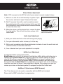
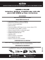
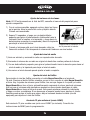
INSTALLATION INSTRUCTIONS FOR PART INSTGMOS-LAN-02
GMOS-LAN-02
GM LAN 29 Amplified OnStar
Interface 2006-up
APPLICATIONS
See inside front cover
KIT FEATURES
•
•
•
•
•
•
•
•
•
•
•
•
•
Provides accessory (12-volt 10-amp)
Retains R.A.P. (Retained Accessory Power)
Used in amplified systems
Retains chimes
Provides NAV outputs (Parking Brake, Reverse, Mute, V.S.S.)
ASWC harness included (ASWC not included)
Retains OnStar/OE Bluetooth
Adjustable volume for chimes and OnStar
High level speaker input
USB updatable
Retains balance and fade
Retains factory back-up camera
Includes antenna adapter
INTERFACE COMPONENTS
GMOS-LAN-02 interface • 16 pin harness with stripped leads • 18-pin harness to 30 pin
GM harness with stripped leads • BACKUPCAM harness • Antenna adapter
• Cutting tool • Crimping tool • Tape • Connectors (example: butt-connectors, bell caps, etc.)
ISO
M4
M3.5
IGNITION
TERMINALS
M2.6
M3
6
2.5
WIRE
CUTTER
1.5
M5
METRA. THE WORLD’S BEST KITS.™
metraonline.com
1-800-221-0932
© COPYRIGHT 2004-2011 METRA ELECTRONICS CORPORATION
REV. 12/27/11
TOOLS REQUIRED
GMOS-LAN-02
Applications
(Note: This interface will also work in vehicles listed below that are not equipped with OnStar)
BUICK
Enclave
Lucerne
2007-up
2006-up
CADILLAC
Escalade
DTS
SRX
2007-up
2006-2010
2007-2009
CHEVROLET
Avalanche
Equinox
Express
Impala
Monte Carlo
Silverado (new body)
Suburban
Tahoe
Traverse
2007-up
2007-2009
2008-up
2006-up
2006-2007
2007-up
2007-up
2007-up
2009-up
GMC
Acadia
Savana
Sierra (new body)
Yukon
2007-up
2008-up
2007-up
2007-up
PONTIAC
Torrent
Vibe (For OnStar retention only)
2007-2009
2009
SATURN
Outlook
Vue
2007-2009
2008-2009
Suzuki
XL-7
2007-2008
Caution: Metra recommends disconnecting the negative battery terminal before beginning
any installation. All accessories, switches, and especially air bag indicator lights must be
plugged in before reconnecting the battery or cycling the ignition.
Note: Refer also to the instructions included with the aftermarket radio.
GMOS-LAN-02
Connections to be made
From the 16 pin harness:
• Connect the Red wire to the ignition wire of the aftermarket radio
• Connect the Orange/White wire to the illumination wire of the aftermarket radio. If the
aftermarket radio has no illumination wire just tape off the Orange/White wire.
• Connect the White wire to the left front positive speaker output of the aftermarket radio
• Connect the White/Black wire to the left front negative speaker output of the
aftermarket radio
• Connect the Gray wire to the right front positive speaker output of the aftermarket radio
• Connect the Gray/Black wire to the right front negative speaker output of the
aftermarket radio
• Connect the Green wire to the radio’s left rear positive speaker output.
• Connect the Green/Black wire to the radio’s left rear negative speaker output.
• Connect the Purple wire to the radio’s right rear positive speaker output.
• Connect the Purple/Black wire to the radio’s right rear negative speaker output.
• Connect the Blue/White wire to the radio’s amp turn on wire
• Connect the Brown wire to the mute wire of the aftermarket radio. If the aftermarket
radio does not have a Mute wire, tape up the Brown wire.
• Connect the Light Green wire to the parking brake wire of the aftermarket
navigation radio.
• Connect the Blue/Pink wire to the VSS or speed sense wire of the aftermarket
navigation radio.
• Connect the Green/Purple wire to the reverse wire of the aftermarket navigation radio.
• Plug the 16 pin harness into the GMOS-LAN-02
3
GMOS-LAN-02
Connections to be made
From the 30 pin harness:
• Connect the Yellow wire to the radio’s 12 volt battery or memory wire.
• Connect the Black wire to the radio’s ground wire.
• Plug the 14 pin harness into the GMOS-LAN-02
• The Black/Yellow wire is for the OnStar volume adjustment. This will be discussed in
the OnStar Level Adjustment section of this instruction.
The 12 pin harness (ASWC plug) will be discussed later in the manual.
BACKUPCAM harness:
This harness is used when you are trying to retain the factory Back up camera. Plug the
yellow RCA of the BACKUPCAM harness to your aftermarket radios video input.
Installing the GMOS-LAN-02
• With all connections completed to the aftermarket radio, plug the 30 pin harnesses into
the vehicles wiring harnesses.
• Reconnect the negative battery terminal.
• Cycle the key, by turning the ignition on for 30 seconds. Then off and on again to test the
radio.
Testing the GMOS-LAN-02
1) Turn the ignition on if not already, and then turn the radio on to verify that the radio
works. Check balance and fader controls for proper operation.
2) Push the OnStar button (if equipped) to verify OnStar is working. The radio will shut off or
mute, depending if the Brown wire on the 16 pin harness is connected, and Onstar will
be heard through the front speakers. Turn off Onstar and the radio will turn back on.
Continue on next page
4
GMOS-LAN-02
Chime Volume Adjustment
Note: If Y91 is present on the RPO list, refer to your owner’s manual to adjust chimes.
1) With car on, shut off car and leave keys in ignition. Open
the car door and leave it open. Chimes will be heard.
2) Wait 10 seconds, then with a small screwdriver adjust
the potentiometer fully counterclockwise (all the way left),
then clockwise to raise chime level and counterclockwise
to lower the chime level.
3) When the volume is at the desired level, remove the keys
from the ignition. This will lock the chime volume at its
Potentiometer located on 16 pin
current level.
side of the interface
Audio Level Adjustment
1) Start your vehicle and turn on the radio having audio playing.
2) Turn your aftermarket radio’s volume up ¾ of the way.
3) With a small screwdriver adjust the potentiometer clockwise to raise the audio level and
counterclockwise to lower the audio level.
4) Once at desired level your audio adjustment is complete.
OnStar Level Adjustment
To adjust the OnStar volume level find the
Black/Yellow wire on the 16 pin harness. Push the blue OnStar button, while the voice is
speaking tap the Black/Yellow wire to ground. There are 4 volume settings for OnStar;
once the 4th setting is reached and the Black/Yellow wire is tapped to ground it will
automatically go back to the first volume setting. Once the volume is set it will stay at
that volume until the Black/Yellow wire is tapped to ground again. This can be set during
installation and then left alone. If user adjustment is desired, the customer may also tap
volume up or down on the steering wheel (if equipped) to adjust the OnStar level.
Additional 12 pin harness (ASWC harness)
This 12 pin harness is to be used in conjunction with the ASWC (not included).
Please refer to ASWC instructions for programming.
5
Notes
Notes
INSTALLATION INSTRUCTIONS FOR PART INSTGMOS-LAN-02
IMPORTANT WARNING
This product includes instructions for installation which must be carefully
followed. The instructions are worded in such a manner to assume
that the installer is capable of completing these type of electronic
installations. If you are unclear as to what you are instructed to do or
believe that you do not understand the instructions so as to properly and
safely complete the installation you should consult a technician who
does have this knowledge and understanding.
Failure to follow these instructions carefully and to install the
interface as described could cause harm to the vehicle or to safety
systems on the vehicle. Interference with certain safety systems
could cause harm to persons as well. If you have any questions in
this regard please call the Help line or Metra at
1-800-221-0932 for assistance.
KNOWLEDGE IS POWER
Enhance your installation and fabrication skills by
enrolling in the most recognized and respected
mobile electronics school in our industry.
Log onto www.installerinstitute.com or call
800-354-6782 for more information and take steps
toward a better tomorrow.
REV. 12/27/11
Metra recommends MECP
certified technicians
METRA. THE WORLD’S BEST KITS.™
metraonline.com
1-800-221-0932
© COPYRIGHT 2004-2011 METRA ELECTRONICS CORPORATION
INSTRUCCIONES DE INSTALACIÓN PARA LA PIEZA INSTGMOS-LAN-02
GMOS-LAN-02
Interfaz OnStar amplificada LAN 29
para GM 2006 y más recientes
APLICACIONES
Vea la lista de aplicaciones en el interior
CARACTERÍSTICAS DEL KIT
•
•
•
•
•
•
•
•
•
•
•
•
•
Proporciona accesorio (12 voltios 10 amperes)
Retiene R.A.P. (Corriente de accesorio retenida)
Se usa en sistemas amplificados
Retiene los tonos
Proporciona salidas de NAV (freno de mano, reversa, silencio, V.S.S.)
Arnés de ASWC incluido (ASWC no incluido)
Retiene el bluetooth OnStar / de fabricante original
Volumen ajustable para tonos y OnStar
Entrada de bocina de alto nivel
Adaptable a USB
Retiene el balance y la intensidad
Incluye adaptador de antena
Retiene la cámara de reversa de fábrica
COMPONENTES DE LA INTERFAZ
Interfaz GMOS-LAN-02 • Arnés de 16 pins con conectores pelados• Arnés de 18 pins
a arnés de GM de 30 pins con conectores pelados
• Herramienta de corte • Cinta • Herramienta engarzadora
• Conectores (p. ej., conectores a tope, tapas acampanadas, etc.)
ISO
M4
M3.5
IGNITION
TERMINALS
M2.6
M3
6
2.5
WIRE
CUTTER
1.5
M5
METRA. THE WORLD’S BEST KITS.™
metraonline.com
1-800-221-0932
© COPYRIGHT 2004-2011 METRA ELECTRONICS CORPORATION
REV. 12/27/11
HERRAMIENTAS REQUERIDAS
GMOS-LAN-02
Applications
(Nota: Esta interfaz también funcionará en los vehículos enumerados a continuación
que no están equipados con OnStar)
BUICK
Enclave
Lucerne
2007 y mas
2006 y mas
GMC
Acadia
Savana
Sierra (nuevo órgano)
2007 y mas
2008 y mas
2007 y mas
CADILLAC
Escalade
DTS
SRX
2007 y mas
2006-2010
2007-2009
Yukon
2007 y mas
PONTIAC
Torrent
Vibe
CHEVROLET
Avalanche
Equinox
Express
Impala
Monte Carlo
Silverado (new body)
Suburban
Tahoe
Traverse
2007-2009
2009
2007 y mas
2007-2009
2008 y mas
2006 y mas
2006-2007
2007 y mas
2007 y mas
2007 y mas
2009 y mas
(Para la retención de OnStar solamente)
SATURN
Outlook
Vue
2007-2009
2008-2009
Suzuki
XL-7
2007-2008
PRECAUCIÓN: Metra recomienda desconectar el terminal negativo de la batería antes de
comenzar cualquier instalación. Todos los accesorios, interruptores y, especialmente, las
luces indicadoras de airbag deben estar enchufados antes de volver a conectar la batería o
comenzar el ciclo de ignición.
Nota: Remítase a las instrucciones incluidas con el radio de postventa.
GMOS-LAN-02
Conexiones que se deben hacer
Desde el arnés de 16 pins:
• Conecte el cable Rojo con el cable de ignición del radio de mercado secundario.
• Conecte el cable Anaranjado/Blanco con el cable de iluminación del radio de mercado
secundario. Si el radio de mercado secundario no tiene cable de iluminación solo cubra
con cinta el alambre anaranjado.
• Conecte el cable Blanco con la salida de la bocina positiva frontal izquierda del radio de
mercado secundario.
• Conecte el cable Blanco/Negro con la salida de la bocina negativa frontal izquierda del
radio de mercado secundario.
• Conecte el cable Gris con la salida de la bocina positiva frontal derecha del radio de
mercado secundario.
• Conecte el cable Gris/Negro con la salida de la bocina negativa frontal derecha del
radio de mercado secundario.
• Conecte el cable Verde con la salida de la bocina positiva izquierda de atrás del radio.
• Conecte el cable Verde/Negro con la salida de la bocina negativa izquierda de
atrás del radio.
• Conecte el cable Púrpura con la salida de la bocina positiva derecha de atrás del radio.
• Conecte el cable Púrpura/Negro con la salida de la bocina negativa derecha de atrás
del radio.
• Conecte el cable Azul/Blanco con el cable de encendido del amplificador.
• Conecte el cable Café con el cable de silencio del radio de mercado secundario. Si el
radio de mercado secundario no tiene un cable de Silencio, encinte el cable Café.
• Conecte el cable Verde claro con el cable del freno de mano del radio de
mercado secundario.
• Conecte el cable Azul/Rosa con el cable VSS o de detección de velocidad del radio de
navegación de mercado secundario.
• Conecte el cable Verde/Púrpura con el cable de la reversa del radio de
mercado secundario.
• Conecte el arnés de 16 pins en el GMOS-LAN-02.
3
GMOS-LAN-02
Conexiones que se deben hacer
Desde el arnés GM de 30 pins:
• Conecte el cable Amarillo con la batería de 12 voltios o el cable de memoria del radio.
• Conecte el cable Negro con el cable de puesta a tierra del radio.
• Conecte el arnés de 14 pins en el GMOS-LAN-02
• El cable Negro/Amarillo es para el ajuste de volumen de OnStar. Esto se explicará en la
sección Ajuste del nivel de OnStar de este instructivo.
El arnés de 12 pins (conector ASWC) se explicará más adelante en el manual.
Arnés BACKUPCAM:
Este arnés se usa cuando trata de retener la cámara de reversa de fábrica. Conecte el RCA
amarillo del arnés BACKUPCAM con su entrada de video del radio de mercado secundario.
Instalación del GMOS-LAN-02
• Cuando termine todas las conexiones en el radio de mercado secundario, conecte los
arneses de 30 pins en los arneses de cables del vehículo.
• Reconecte la terminal de la batería negativa.
• Cicle la llave, encendiendo la ignición durante 30 segundos. Después apague y encienda
de nuevo para probar el radio.
Prueba del GMOS-LAN-02
1) Prenda la ignición si no lo ha hecho, y después prenda el radio para probar si funciona.
Revise que funcionen bien los controles de balance e intensidad.
2) Presione el botón de OnStar (si lo tiene) para verificar que OnStar esté funcionando. El
radio se apagará o se pondrá en silencio, dependiendo de si el cable Café del arnés de
16 pins está conectado, y se escuchará OnStar por las bocinas frontales. Apague OnStar
y el radio se volverá a prender.
Continúa en la página
4
GMOS-LAN-02
Ajuste del volumen de los tonos
Nota: Si Y91 está presente en la lista de RPO, consulte el manual del propietario para
ajustar campanillas.
1) Con el coche encendido, apagado coche y dejar las llaves
en la ignición. Abra la puerta del coche y dejarlo abierto.
Chimes será escuchado.
2) Espere 10 segundos, y luego con un destornillador
pequeño para girar el potenciómetro totalmente hacia la
izquierda (todo el camino a la izquierda), y luego hacia la
derecha para aumentar la campanada y hacia la izquierda
para bajar el nivel del timbre.
Potenciómetro situado en el lado
de 16 pines de la interfaz
3) Cuando el volumen está en el nivel deseado, retire las
llaves del contacto. Esto bloqueará el volumen del timbre en su nivel actual.
Ajuste del nivel de audio
1) Inicie su vehículo y encienda la radio con reproducción de audio.
2) Encienda el volumen de su radio no original de hasta tres cuartas partes de la forma.
3) Con un destornillador pequeño para girar el potenciómetro hacia la derecha para elevar el
nivel de audio y la izquierda para bajar el nivel de audio.
4) Una vez en el nivel deseado puede ajustar el audio completo.
Ajuste del nivel de OnStar
Para ajustar el nivel de OnStar, encuentre el cable Negro/Amarillo en el arnés de
16 pins. Presione el botón OnStar, mientras se oye la voz, conecte el cable Negro/Amarillo
a tierra. Hay 4 ajustes de volumen para OnStar; una vez que llegue al 4o ajuste y el cable
Negro/Amarillo se toca a tierra, automáticamente regresará al primer ajuste de volumen.
Una vez que el volumen esté ajustado se quedará en ese volumen hasta que el cable
Negro/Amarillo se toque a tierra de nuevo. Esto puede ajustarse durante la instalación
y luego no volver a cambiarse. Si se desea que el usuario pueda hacer ajustes, el cliente
también puede pulsar el botón que sube o baja el volumen desde el volante (si está
equipado) para ajustar el nivel de OnStar.
Arnés de 12 pins adicional (arnés ASWC)
Este arnés de 12 pins se debe usar junto con el ASWC (no incluido). Consulte las
instrucciones de ASWC para la programación.
5
Notas
Notas
INSTRUCCIONES DE INSTALACIÓN PARA LA PIEZA INSTGMOS-LAN-02
ADVERTENCIA IMPORTANTE
Este producto incluye instrucciones de instalación que deben seguirse
cuidadosamente. Dichas instrucciones están redactadas dando por
supuesto que el instalador es capaz de completar estos tipos de
instalaciones electrónicas. Si tiene dudas respecto de lo que se le
indica que haga o cree que no comprende las instrucciones como para
completar la instalación en forma adecuada y segura, debe consultar a
un técnico que efectivamente tenga estos conocimientos y comprensión.
Si no sigue estas instrucciones con cuidado y no instala la
interfaz como se describe, podría provocar daños en el vehículo
o en los sistemas de seguridad del vehículo. La interferencia con
determinados sistemas de seguridad también podría provocar
daños a las personas. Si tiene alguna pregunta al respecto,
llame a la línea de ayuda o a metra, al 1-800-221-0932 para
obtener asistencia.
CONOCIMIENTO
ES PODER
KEL
NOWLEDGE
IS POWER
Mejoreyour
susinstallation
habilidadesand
de fabrication
instalación skills
y fabricación
Enhance
by
enrolling
in the most
anddispositivos
respected
inscribiéndose
en recognized
la escuela de
mobile electronics school in our industry.
electrónicos móviles más reconocida y respetada de
Log onto www.installerinstitute.com or call
nuestra industria.
Regístrese
en and
www.installerinstitute.
800-354-6782
for more
information
take steps
comaobetter
llame tomorrow.
al 800-354-6782 para obtener más
toward
información y avance hacia un futuro mejor.
REV. 12/27/11
Metra recomienda técnicos con
certificación del Programa de
Certificación en Electrónica Móvil
(Mobile Electronics Certification
Program, MECP).
METRA. THE WORLD’S BEST KITS.™
metraonline.com
1-800-221-0932
© COPYRIGHT 2004-2011 METRA ELECTRONICS CORPORATION