1
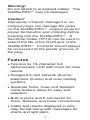
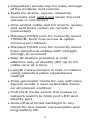
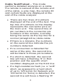
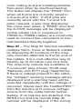
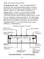
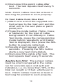
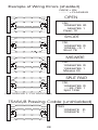
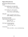
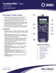
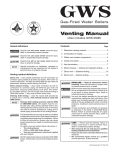
TestifierPROf Test Set www.jdsu.com/hbn User's Guide a2007 JDSU.All rights reserved. Telephone Jack Data Jack F-Connector Jack (Coax) Coax Mode Button LCD Screen Network Mode Button Telco Mode Button Up Button Setup Power Button Down Button Select Button Remote Telephone Jack Data Jack Table of Contents Features���������������������������������������������� 1 Description������������������������������������������ 3 Instructions for Use�������������������������� 17 Cable Testing������������������������������� 17 To Map Cable ID’s������������������������ 20 To Place Tone on a Cable ����������� 20 To Measure Length���������������������� 21 To Perform Hub Blink ������������������ 23 Interpreting cable Test Results���������������������������������������������� 24 Battery Replacement������������������������ 29 Specifications ���������������������������������� 30 Accessories ���������������������������������� 32 Warranty�������������������������������������������� 33 Shipping��������������������������������������� 35 Support Service��������������������������� 35 Warning! Do not attach to energized cables. The TestifierPRO may be damaged. Caution! Improperly crimped, damaged or uncrimped plugs can damage the jacks on the TestifierPRO. Inspect plugs for proper termination and crimping before inserting into the TestifierPRO. A Sacrificial Cable (TP74) can be used to extend the life of the RJ45 jack of the TestifierPRO. Contacts should always be recessed into the plastic grooves of the plug. Features •Two-line by 16-character full alphanumeric LCD with icons for clear results •Designed to test network (8-wire), telephone (6-wire) and coax cabling systems •Separate Telco, Coax and Network mode buttons allow for easy test selection •Built-in jacks and F-connector for Telco, Network and Coax connections •Cable test results displayed in wire map format along with messages for shorts and split pairs •Integrated remote bay for easy storage of the modular test remote •Tests for shorts, opens, miswires, reversals and split pairs when the test remote is connected •One-ended cable test for shorts, opens and split pairs (when no remote is connected) •Displays PASS icon for correctly wired T568A/B, both one-to-one & uplink (cross-over) cables •Displays PASS icon for correctly wired 6-pin telephone cables both straightthrough & reversed •Map ID feature provides a cost effective way to identify (ID) up to 20 cable runs at a time. •Length measurement in feet or meters using patented cable capacitance method •Tone generator mode for use with tone tracers sends 4 user-selectable tones on all pin/pair combos •Hub blink mode sends link pulses to network switch to blink port LED and identify port •Auto-off and timed backlight in any mode for low power consumption and long battery life Description The TestifierPRO is designed to test all common low-voltage cabling systems found in today’s automated homes, telephone, network or video. It has an LCD display and eight momentary buttons. The TestifierPRO has three modes of operation (Telco, Coax and Network), each with a dedicated button for easy test selection. In addition, a Setup key is provided to allow for easy access and selection of user-settable options. The main unit comes with built-in jacks and F-connector for Telco, Network and Coax cables. It has an integrated remote bay that houses a detachable test remote for patch cable testing. The test remote has built-in jacks for Telco and Network cables. The TestifierPRO can be turned on by pressing the Power button or any of the three mode buttons. At power up, the TestifierPRO returns to the same menu item or execution mode right before it was last turned off. This allows the user to power off and on the unit within a long task without re-configuring the unit every time it has been turned off. When the TestifierPRO is turned on for the first time after a new battery is installed, the unit is initialized to the default menu item Telco Cable Test. Pressing the mode button repeatedly cycles through all the menu items available for that mode: Telco Mode Coax Mode Network Mode Cable Test p Map ID p Length p p p Tone p p p p p p Hub Blink p While the unit is on, pressing any of the three mode buttons (Telco, Coax or Network) brings up the same menu item previously selected for that mode. Pressing the Power button momentarily (for less than 2 seconds) toggles the EL backlight. Pressing the Power button for more than 2 seconds turns off the unit. When the unit is off, pressing the Power button turns on the unit. While the unit is off, holding down the SETUP key and then pressing the Network button starts the unit in Diagnostic mode. Key Description: Key Feature Description Telco mode button Coax mode button Network mode button Up and down buttons SEL Select button SETUP Setup mode button Power button Cable Test/Pretest – This mode performs detailed analysis on a cable. If a remote is sensed at the remote end of the cable, a wire map, the remote ID and certain faults are displayed at the end of the cable analysis: • There are two lines of numbers displayed at the end of the test. The top line of numbers on the display represents the connector pins on the main unit. The second line of pin numbers is the connector pin numbers of the remote, normally being the same as the top line for a normal (straight-thru) data cable. • If there is a miswire, the numbers on the second line indicate the pin numbers detected. • If no connection is detected for some of the pins, the second line will be blank in those pin locations. • If a short is detected, the second line will have a flashing ‘X’ in that position and the specific short condition displayed on the third line. • If a high-resistance fault (i.e. a “soft” short, as opposed to a hard short, of up to 125 kohm for Network and 100 kohm for Telco) is detected, the second line will have a flashing ‘R’ in that position and a message of “High-R Fault” displayed on the third line. • If a split pair is detected, corresponding pin positions on the second line will display flashing pin numbers detected from the remote. The specific split conditions are displayed on the third line. • If there are multiple errors to display on the third line, messages for the highest severity errors are displayed in sequence until all are displayed. So if there are both shorts and high-R Faults, only messages for the shorts are cycled through. The ID icon will have a number directly below it indicating the remote ID number. If there is no remote, the TestifierPRO uses the length and cable test capability to attempt to measure a cable for shorts, opens and split pairs (Pretest.) While the test is in progress the test icon and the wire numbers for the pair being test are displayed. The final test results are displayed as messages on the LCD. Because a test can take up to about 5 seconds to complete, the SEL button, which immediately starts a new test, should be pressed whenever a new cable is connected and ready for test. Partial and erroneous results will be displayed until a complete test cycle has been run on a cable. For Telco Cable Test mode, the TestifierPRO assumes that the 6position Telco jacks on the main unit and the remote will be used for connecting the tester to the cable run to be tested. This mode uses the 3-pair USOC standard to define the pairs. Connector pins 1-6, 2-5 and 3-4 are the pairs defined by this standard. The tester will display the “PASS” icon when all 6 pins are correctly wired in a one-to-one order. If all 6 pins are correctly wired in the reverse order, the “PASS” icon along with a flashing “Rev” icon will be displayed. Standard telephone cables used between a phone set and a wall jack are usually reverse-pinned. For Network Cable Test mode, the TestifierPRO assumes that the 8position Network jacks on the main unit and the remote will be used for connecting the tester to the cable run to be tested. The TIA/EIA 568A/B standard is used to define the pairs. Connector pins 1-2, 3-6, 4-5 and 7-8 are the pairs defined by this standard. The A and B standards are the same except for the color coding and are indistinguishable from each other by electrical testing. The tester will display the “PASS” icon when all 8 pins are correctly wired in a one-to-one order. If all 8 pins are correctly wired with the 1-2 and 3-6 pairs crossed, a wire map displaying the cross-over wires, a “PASS” icon and the X-OVR message will be displayed. Uplink cables (a.k.a. crossover or T568A-to-T568B cables) are commonly used to connect two computers or two hub/switches directly together. Map ID – The Map ID function identifies multiple Telco, Coax or Network cables by displaying ID numbers of the maponly remotes attached to the far end of the cables. It is a cost effective way to identify up to 20 cable runs at a time. The map-only remote are available in F-connector plug (Coax), RJ45 plug (Network) and RJ11 plug (Telephone). If there is voltage present in the cable, the “Voltage!” warning message will be displayed and a warning beep will be sounded repeatedly until the voltage is removed. Disconnect the TestifierPRO from the live line and remove voltage source from the cable before further testing. If no failures are detected, the PASS icon and the remote Map ID number will be displayed. If the wrong type of map-only remote is used (e.g. a Coax remote used in Telco mode), a message with the remote type identified will be displayed. If a full-remote instead of a map-only remote is used, an error message will be displayed. If no remote is found, or if the cable is shorted, the OPEN or SHORT icons will be displayed respectively. Length – Length mode measures the length of a cable by measuring its capacitance and using the useradjustable capacitance per unit length (the length constant) to calculate the cable length. The TestifierPRO supports three user-adjustable length constants - one for each type of cables. The TestifierPRO remembers these constants even when the unit is powered off as long as a good battery is connected to the unit. In Network mode, cross-over cables are recognized by displaying the PASS icon and the “X-OVER” message after the length. In Telco mode, reverse-pinned cables are recognized and a “REV-PIN’D” message added after the measured length value. The PASS icon is displayed if it is a correctly wired reverse-pinned 6-position cable. 10 The measured length value is displayed on the LCD along with the current value of the length constant. Pressing the SEL button cycles the pair being measured in the following sequence: For Network mode: auto-select, 1-2, 3-6, 45, 7-8. For Telco mode: auto-select, 1-6, 2-5, 3-4. For Coax mode: Pin + Shield (the only option for Coax cable). The pair number is displayed next to the length except in auto-select mode. If a selected pair has a fault, the fault replaces the length reading on the LCD. In auto-select mode, the TestifierPRO automatically selects a pair without a fault. Users can adjust the length constant using the up and down arrows. The CAL icon is displayed when the TestifierPRO recalculates internal coefficients. If network terminator patterns are found in length mode, the TestifierPRO will display messages including “T Ring Network?”, “xbaseT Network?” or “Network?” to alert the user of the unexpected terminator patterns. In length mode, if a full remote is present at the other end of the cable, the ID number for the full remote is displayed. Do not use map-only remotes in length mode. If the cable length measured is longer then the specified maximum length (roughly 2000 feet for 11 CAT 5/6 cable), the error message “> Max Length” will be displayed. Tone – The tone mode generates audio tones for use with tone tracers on all pairs, a selected pair or a selected pin. The signal generated on a pair has the signal on one pin and the complement of the signal on the other pin of the pair, yielding a nominal 10 volts peak-to-peak across the pair. The pin(s) being driven with tone and the currently selected tone pattern are displayed on the screen along with the “Tone” icon and the icon for the connector assumed to be used. Once in the tone generator mode, use the up and down buttons to step to the next connector pin(s) drive option. When the SEL button is pressed and held down for longer than 1 second, the tone pattern options are automatically cycled through until the button is released. The tone pattern options are Hi, Lo, Tone 1 and Tone 2. The last two options are dual or warble tones of differing pattern duration. Press any mode buttons or the Power button to exit Tone mode. Hub Blink – Hub blink mode sends link pulses to the network switch to blink the port LED and identify the port the Network cable connected to. The Hub 12 Blink mode sends link pulses to the NIC transmit pair for 3 seconds and then stops for 3 seconds (for an overall cycle time of 6 seconds.) It is necessary to go this slow for some switches and hubs from some major manufacturers. The TEST icon is displayed when the unit sends link pulses and off when not. Setup – The setup mode is used to set user-selectable options. Use the up and down buttons to scroll through settable options. Use the SEL button to change the current setting to the alternate option. Press any mode key or the Power key to exit Setup mode and save the updated parameters. • The beep-on-pass for cable test can be turned on or off (default is on). • The pass criteria can be set for shielded or unshielded cables (default is unshielded). • The length and length constants can be set for meters or feet (default is feet). If the length unit (meters or feet) is changed, TestifierPRO automatically converts the length constants from the old unit to the new unit on exit of setup mode. 13 Voltage Check – The TestifierPRO continuously monitors voltage level on its RJ jack and F-connector in all modes (including menu selection) when it is on. When it detects voltage, the “VOLTAGE!!” warning message appears on the screen and the beeper sounds until the voltage is removed. The TestifierPRO is designed to withstand input voltage conditions that occur during normal telephony applications for a short period of time (approx. 10 seconds). Diagnostic – While the unit is off, holding the SETUP key and pressing the NETWORK button powers up the unit in diagnostic mode. Step 1 of diagnostic mode displays the revision of the firmware being used. Step 2 activates all elements of the LCD for a visual check of the LCD panel. Step 3 allows user to make 8 key presses to verify button operation: T for Telco mode button, C for Coax mode button, N for Network mode button, ∧ for up button, S for Select button, ∨ for down button, U for Setup button and P for Power button. Within these 8 key presses the user can press any key in any order in any repeating manner. The ninth key press starts a diagnostic test on the built-in remote. Connect the built-in remote with 14 a known-good network cable and press the SEL key to initiate a new test cycle. The remote diagnostic test verifies that the two redundant ID’s in the remote unit are both functional. If either of the two redundant ID’s is defective, no ID number will be displayed in diagnostic mode. During normal cable test, the TestifierPRO needs only one of the two redundant ID’s to be functional to recognize and display the remote ID. Battery Low Detection – The TestifierPRO monitors battery status continuously when it is powered on. When the battery low icon is activated, battery voltage has dropped to below 6.4V. The battery should be replaced as soon as practical. Below 6.0V, the LCD display could dim or appear turned off even though the TestifierPRO is still operating (for example, the EL backlight can still be toggled.) Cable testing results becomes unreliable when battery voltage drops below 4.5V. EL Backlight – At power on, the EL backlight is initialized to off to conserve power. While the TestifierPRO is on the backlight can be toggled on and off by momentarily pressing the power key (for less than 2 seconds). The backlight turns off automatically roughly 3 minutes 15 after the last key press. Autopower off – The TestifierPRO powers off automatically after a fixed period of continuous operation in any given mode: 2 minutes in Setup or diagnostic mode; 10 minutes while displaying menu selection item; 18 minutes while executing cable test, map ID, or length measurement; 70 minutes while executing tone trace or hub blink. Be sure to install a battery if using the TestifierPRO for the first time, see battery installation. Adjusting Length Constant Cable Has Shorts or Splits Setup Mode Test in Progress Cable PASSED T568A/B PASS FAIL CAL SETUP TEST 1 2 3 4 5 6 7 8 S ID Beeper Off Icon Battery Low Icon Main Unit Pin Numbers Alphanumeric Characters ID Number Icon (Remote ID Displayed Below It) TestifierPRO LCD Display 16 Instructions for Use Cable Testing Note: Be sure to set up the unit for shielded or unshielded cable in Setup mode before performing any cable test. To Test a Patch Cable (see caution about cables with bad plugs above) 1) Plug one end of the patch cable into the main unit. 2) Remove the remote unit from the main unit by squeezing both the top and the bottom center areas of the remote and sliding it out of the remote bay at the bottom of the main unit. Plug the other end of cable into the remote unit. 3) Press the mode button (Telco, Coax, or Network) for the type of cable being tested. If not already in cable test mode, press the corresponding mode button repeatedly until the Cable Test menu item is displayed, then press the SEL button to execute cable test. The TestifierPRO indicates a test in progress by displaying the TEST icon. It sounds a beep (if enabled), displays the wire map result and a PASS icon if the cable passes the T568A/B standard and the configured shield criteria. 17 4) Disconnect the patch cable after test. The test repeats itself every 5 seconds. Note: Patch cables must be at least 4 feet long for pretest to work properly. To Test Cable from One End 1) Attach one end of the supplied onefoot jumper to the main unit and the other end to the wall plate or patch panel jack. 2) Press the mode button (Telco, Coax, or Network) for the type of cable being tested. If not already in Cable Test mode, press the corresponding mode button repeatedly until Cable Test is displayed, then press the SEL button to execute cable test. 3) Results should appear within 5 seconds. Pressing the SEL button starts a new test immediately. 4) Disconnect the cable after test. The test repeats itself every 5 seconds. Application Hint: The jumper cables must be short compared to the cable run for accurate open and split pair indication, i.e. no more than 10% of the total run length or 3 feet, whichever is less. Patch cables must be at least 4 feet long for pretest to work properly. 18 To Test Installed Cable (office jack to patch panel with remote) 1) Remove the remote unit from the main unit by sliding the remote towards the top of the main unit. 2) Attach one end of the supplied onefoot patch cable to the remote and other end to the wall jack. 3) Attach one end of the second supplied one-foot patch cable to the main unit and the other end to the patch panel jack. 4) Press the mode button (Telco, Coax, or Network) for the type of cable being tested. If not already in Cable Test mode, press the corresponding mode button repeatedly until Cable Test is displayed and then press the SEL button to execute cable test. The TestifierPRO indicates a test in progress by displaying the TEST icon. If the cable passes the set shield criteria and the T568A/B standard, the TestifierPRO displays within 2 seconds a wire map and a PASS icon and sounds a beep (if enabled). The ID number for the remote will also be displayed. 5) Disconnect the cable after test. The test repeats itself every 5 seconds. Application Hint: The jumper cables must be short compared to the cable run 19 for accurate split pair indication, no more than 10% of the total run length. To Map Cable ID’s 1) Turn on the unit by pressing the mode button for the type of cable being tested (i.e. the Telco, Coax, or Network button.) If not already in Map ID mode, press the corresponding mode button repeatedly until Map is displayed and then press the SEL button. 2) Connect the cable to be mapped to the main unit. Insert a map-only remote to the jack at the far end of the cable. 3) A PASS icon and the ID number for the map-only ID will be displayed. The type of cable (Telco, Coax, or Network) being tested is indicated at the lower left corner of the screen. A FAIL icon along with an error message (OPEN or SHORT) will be displayed if there is an open or short in the cable. To Place Tone on a Cable 1) Press the mode button (Telco, Coax, or Network) for the type of cable being tested. If not already in Tone test, press the corresponding mode button repeatedly until the Tone 20 menu item is displayed on the screen and then press the SEL button. 2) Repeatedly press the SEL button until the desired tone is selected. The up/down arrow keys select the pin or pair(s) that carries the tone. 3) Connect the cable to be traced to the main unit. For best tone signal, do not attach a remote unit at the other end of the cable. Due to the shielding effect of a twisted pair, a stronger signal can be obtained by having only one wire of a twisted pair carrying the tone. Selecting a single pin instead of a pair will achieve this. 4) To turn tone off, press any of the three mode buttons. To Measure Length 1) Connect cable to main unit. (A remote may or may not be present at other end). 2) Press the mode button (Telco, Coax, or Network) for the type of cable being tested. If not already in Length mode, press the mode button until the Length menu item is displayed and then press the SEL button. Cable length will be displayed. • Use the up and down arrow keys to adjust the length constants (unit in pF/feet or pF/ m). 21 • • To change the pair measured, press the SEL button to cycle through the pairs available for that mode – For Network mode: auto-select, 1-2, 3-6, 4-5, 7-8. For Telco mode: auto-select, 16, 2-5, 3-4. For Coax mode: Pin + Shield (the only option). To change length between feet and meters, use Setup mode. Note: After a new battery is installed, the default length constants are initialized to 15 pF/foot for Network cable, 22.5 pF/foot for Coax cable and 17.5 pF/foot for Telco cable. For Network cable, most Cat 5, Cat 5e & Cat 6 cables have unit capacitances close to 15pF/foot – check with your cable manufacturer for possible variances). Note: If a selected pair has a fault, the fault replaces the length reading on the LCD. In default mode, if the 1-2 pair has a fault, The TestifierPRO automatically sequences to a pair without a fault. 22 Unknown Length Constant If “length constant” is unknown for a particular cable, a known length of the same type of cable may be used to calibrate the constant. Attach fifty feet or more of a similar cable from the same manufacturer to the main unit. Repeatedly press the mode button for the type of cable being tested until Length is displayed. Press up/down arrow keys until 50ft is displayed. The length constant displayed is what should be used to measure the length of the unknown cable for the same model and from the same manufacturer. Fifty feet or more is suggested to minimize the resolution error; 1 foot in 50 is 2% of uncertainty. To Perform Hub Blink 1) Attach the main unit to the network cable which has the other end connected to a switch, router, or hub. 2) Press the Network mode button on the TestifierPRO repeatedly until Hub Blink is displayed on the screen and then press the SEL button. 3) The LED corresponding to the network cable under test should blink at a rate of 6 seconds per cycle (3 seconds on and 3 seconds off.) 4) To exit Hub Blink mode, press the Network mode key. 23 Interpreting cable Test Results The PASS icon will be displayed if the cable has all pins properly connected per T568A/B for network cables or per 3-pair USOC for telephone cables. The FAIL icon will be displayed if there is a wiring error. The wire map will display the end-to-end connections measured whenever possible. The PASS icon will also be displayed if a network cable has the 1-2 and the 3-6 pairs transposed to indicate a properly wired uplink (crossover) cable. In Telephone mode, the “Reversed Pin” message will be displayed if all connected pins are in reverse order and the PASS icon will also be displayed if all 6 connections are present. Telephone modular plug cables used between the wall jack and a phone set are usually reverse pinned. Definition of Errors – (See failure example drawings) The four classes of faults discussed below are in order of severity. The severity has to do with the ability of a more severe error to mask lower severity errors. For example, if there is a short in the cable; miswires and splits pairs may not be detected for the pairs involved in the short fault. 24 Short – The pair has a low resistance connection from one wire of the pair to the other wire of the pair or to any other wire in the cable or the shield. A short is indicated by the Short icon being displayed and flashing X’s in the appropriate pin positions on the second line for the pin numbers involved in the shorts plus a flashing S icon if the shield is shorted to a pin. Miswire – A wire or both wires of a pair are not connected to the correct pins at the other end of the cable. The wire map shows the pin numbers from line 1 (main) to line 2 (remote). A reverse pair is a special case of a miswire in which the pair is wired to the correct pair of pins or to another designated pair of pins, but the two leads are reversed. TestifierPRO is able to test for split pair errors as long as the wiring errors are in pairs. The FAIL icon and the pin numbers, which are miswired, will be flashing. 25 Split Pair – A split pair is an error in the twisting of the wires together within the cable. The cables generally are made up of eight wires twisted together in 4 pairs. These 4 pairs are designated as pairs by the wiring standards and are intended to carry a signal and its return. 1&2, 3&6, 4&5 and 7&8 are the pairs designated by T568A/B for a RJ45 jack or plug. A cable can be wired with correct continuity but not with correct pairing. This most often happens when the cable is terminated consistently at both ends, but in the wrong order. A dynamic or AC test is required to detect this type of error. If the only error is a split pair error, the cable has correct continuity. If cross talk is not a concern, as in flat satin cable, the cable is good if the only error is the split pair error. The Split icon and the pin numbers on the first and second line of the wire map with split pairs flash when there is a split pair error. 26 High-Resistance Fault – If a ‘soft’ short of up to 125 kohm (as opposed to a hard short of 0 ohm) is detected between two pins of the same pair, the second line will have flashing ‘R’ in the two positions corresponding to those two pins. A message of “High-R Fault” will be displayed on the third line. If a ‘soft’ short is detected between two pins of two different pairs, the second line will have flashing ‘R’ in 3 or 4 positions corresponding to the two pairs. For a shielded cable, if a ‘soft’ short is detected between the shield and a single pin, the second line will have flashing ‘R’ in the shield and the pin’s positions. If a ‘soft’ short occurs in certain locations where the TestifierPRO could not resolve the fault down to a single shield-andpin combo, the second line will have a flashing ‘R’ in more than one pin locations. The shield location will be flashing both ‘S’ and ‘?’ to indicate that the shield’s status could not be resolved. 27 Example of Wiring Errors (shielded) DARK = ON LIGHT = FLASHING OPEN 1 2 3 4 5 6 7 8 1 2 3 4 5 6 7 8 1 2 3 4 5 6 7 8 1 2 3 4 5 6 7 8 FAIL 12345678S ID 123456 xx S 1 Short 78 1 2 3 4 5 6 7 8 1 2 3 4 5 6 7 8 FAIL 12345678S ID 13245678S 1 Miswire 23 1 2 3 4 5 6 7 8 1 2 3 4 5 6 7 8 FAIL 12345678S ID 12345678S 1 Split 1236 FAIL 12345678S ID 345678S 1 Open 12 SHORT MISWIRE SPLIT PAIR (1 not twisted with 2; 3 not twisted with 6) T568A/B Passing Cable (unshielded) 1 2 3 4 5 6 7 8 1 2 3 4 5 6 7 8 28 PASS 12345678 12345678 ID 1 Battery Replacement 1) Turn the TestifierPRO over on the backside and place it on a flat surface. 2) Use a Phillips screw driver (No. 2) to remove the battery door screw. 3) Pull the old battery out of the battery compartment and detach the battery cap. 4) Connect a new Alkaline 9 volt battery to the battery cap. 5) Slide the new battery into the battery compartment and close the battery door. 6) Replace the battery door screw using the screw driver. Do not over tighten. When installing a new battery, disconnect any cables connected to the TestifierPRO. The length and pretest modes will be improperly calibrated if a cable is present when a new battery is connected to the TestifierPRO. Hint: TestifierPRO can retain user-defined length constants and last mode of operation for several minutes without power if the unit is turned off before replacing the battery. 29 Specifications Physical Dimensions Size: Excluding F-connector: 3.3 x 6.7 x 15.7 cm 1.3 x 2.6 x 6.2 inches Including F-connector: 3.3 x 6.7 x 16.8 cm 1.3 x 2.6 x 6.6 inches Weight: 235.3 grams (8.3 oz.) with battery and remote Environmental Operating temperature: 0 to 50 OC (32 to 122 OF) Storage temperature: -10 to 60 OC (14 to 140 OF) Humidity: 10% to 90%, non-condensing 30 Battery Life Battery life (based on a typical 9V Alkaline battery) are for the full capacity of the battery used continuously in one of the following modes – Standby: 2.5 years Cable Testing: 80 hours (with backlight off) Cable Types: Shielded or unshielded, Cat-5E, Cat-5, Cat-4, Cat-3 and Coax Minimum cable length for testing for split pairs: 0.91 meter (3 feet) Minimum cable length for PRETEST: 1.22 meter (4 feet) Length measurement range (CAT5/6): 0 to 610 meters (0 to 2000 feet) Coax Cable: 100 ohms maximum DC resistance, center conductor plus shield 31 Accessories TP310 - #1 to 10 F-Connector Mapping Remote TP311 - #1 to 20 F-Connector Mapping Remote TP312 - #1 to 20 RJ45 Plug Mapping Remote TP314 - #1 to 20 RJ11 Plug Mapping Remote TP608 - Set of 7 numbered Full remotes TP20 - 7.5” cable assembly with no-fault 6 position plugs, reverse-pinned. Use to map and test 2, 4 or 6 pin telephone wiring. Can be used with RJ45 (8position) jacks and will not damage them. TP56 - Patch Cable Assembly, RJ45, without shield TP40 - Cable Assembly, RJ45 / Alligator 12” LAN 32 Warranty JDSU guarantees that its products will be free of all defects in material and workmanship. This warranty extends for the period of 12 months for test instruments and 3 months for cables from date of manufacture or purchase (proof of purchase required). All product deemed defective under this warranty will be repaired or replaced at JDSU’s discretion. No further warranties either implied or expressed will apply, nor will responsibility for operation of this device be assumed by JDSU. WEEE Directive Compliance: JDSU has established processes in compliance with the Waste Electrical and Electronic Equipment (WEEE) Directive, 2002/96/EC. This product should not be disposed of as unsorted municipal waste and should be collected separately and disposed of according to your national regulations. In the European Union, all equipment purchased from JDSU after 2005-0813 can be returned for disposal at the end of its useful life. JDSU will ensure that all waste equipment returned is reused, recycled, or disposed of in an environmentally friendly manner, and in compliance with all applicable national 33 and international waste legislation. It is the responsibility of the equipment owner to return the equipment to JDSU for appropriate disposal. If the equipment was imported by a reseller whose name or logo is marked on the equipment, then the owner should return the equipment directly to the reseller. Instructions for returning waste equipment to JDSU can be found in the Environmental section of JDSU’s web site at www.jdsu.com. If you have questions concerning disposal of your equipment, contact JDSU’s WEEE Program Management team at WEEE. [email protected]. 34 Shipping Before returning any product to JDSU, you must first request a Return Merchandise Authorization Number by contacting our Customer Service Dept. at (805) 383-1500. 1) No shipments will be accepted without this number, which must be clearly marked on the shipping label. 2) Ship the equipment with a copy of the sales receipt, if available. 3) Attach a description of the operational problem. 4) Include a contact name, phone number and E-mail address. 5) Pack securely to prevent damage during shipping. 6) Ship prepaid to: JDSU, 808 Calle Plano, Camarillo, CA 93012 Support Service For technical information and support, please visit www.JDSU.com/test-um. 35 Contact Information: 808 Calle Plano Camarillo, CA 93012 USA Regional Sales North America Tel: +1 805 383 1500 Fax:+1 805 383 1595 Latin America Tel: +55 11 5503 3800 Fax:+55 11 5505 1598 Asia Pacific Tel: +852 2892 0990 Fax:+852 2892 0770 EMEA Tel: +49 7121 86 2222 Fax:+49 7121 86 1222 Customer Service www.jdsu.com/customerservice TU9893 (REV A - 04/07)