1
SUPER
®
SC847 CHASSIS SERIES
SC847A-R1400LPB
SC847E1-R1400LPB
SC847E2-R1400LPB
SC847E16-R1400LPB
SC847E26-R1400LPB
SC847A-R1400UB
SC847E1-R1400UB
SC847E2-R1400UB
SC847E16-R1400UB
SC847E26-R1400UB
USER’S MANUAL
1.0b
SC847 Chassis Manual
The information in this User’s Manual has been carefully reviewed and is believed to be accurate.
The vendor assumes no responsibility for any inaccuracies that may be contained in this document,
makes no commitment to update or to keep current the information in this manual, or to notify any
person or organization of the updates. Please Note: For the most up-to-date version of this
manual, please see our web site at www.supermicro.com.
Super Micro Computer, Inc. ("Supermicro") reserves the right to make changes to the product
described in this manual at any time and without notice. This product, including software and
documentation, is the property of Supermicro and/or its licensors, and is supplied only under a
license. Any use or reproduction of this product is not allowed, except as expressly permitted by
the terms of said license.
IN NO EVENT WILL SUPERMICRO BE LIABLE FOR DIRECT, INDIRECT, SPECIAL, INCIDENTAL,
SPECULATIVE OR CONSEQUENTIAL DAMAGES ARISING FROM THE USE OR INABILITY TO
USE THIS PRODUCT OR DOCUMENTATION, EVEN IF ADVISED OF THE POSSIBILITY OF
SUCH DAMAGES. IN PARTICULAR, SUPERMICRO SHALL NOT HAVE LIABILITY FOR ANY
HARDWARE, SOFTWARE, OR DATA STORED OR USED WITH THE PRODUCT, INCLUDING THE
COSTS OF REPAIRING, REPLACING, INTEGRATING, INSTALLING OR RECOVERING SUCH
HARDWARE, SOFTWARE, OR DATA.
Any disputes arising between manufacturer and customer shall be governed by the laws of Santa
Clara County in the State of California, USA. The State of California, County of Santa Clara shall
be the exclusive venue for the resolution of any such disputes. Super Micro's total liability for all
claims will not exceed the price paid for the hardware product.
California Best Management Practices Regulations for Perchlorate Materials: This Perchlorate
warning applies only to products containing CR (Manganese Dioxide) Lithium coin cells. “Perchlorate
Material-special handling may apply. See www.dtsc.ca.gov/hazardouswaste/perchlorate”
WARNING: Handling of lead solder materials used in this
product may expose you to lead, a chemical known to
the State of California to cause birth defects and other
reproductive harm.
Manual Revision 1.0b
Release Date: April 23, 2010
Unless you request and receive written permission from Super Micro Computer, Inc., you may not
copy any part of this document.
Information in this document is subject to change without notice. Other products and companies
referred to herein are trademarks or registered trademarks of their respective companies or mark
holders.
Copyright © 2010 by Super Micro Computer, Inc.
All rights reserved.
Printed in the United States of America
ii
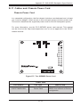
Preface
Preface
About This Manual
This manual is written for professional system integrators and PC technicians. It
provides information for the installation and use of the SC847 chassis. Installation
and maintenance should be performed by experienced technicians only.
This manual lists compatible parts available when this document was published. Always refer to the our Web site for updates on supported parts and configurations.
iii
SC847 Chassis Manual
Manual Organization
Chapter 1: Introduction
The first chapter provides a checklist of the main components included with this
chassis and describes the main features of the SC847 chassis. This chapter also
includes contact information.
Chapter 2: System Safety
This chapter lists warnings, precautions, and system safety. It is recommended that
you thoroughly familiarize yourself with installing and servicing the chassis and all
safety precautions.
Chapter 3: Chassis Components
Refer here for details on this chassis components including the fans, hard drives,
air shrouds, and other components.
Chapter 4: System Interface
Refer to this chapter for details on the system interface, which includes the functions and information provided by the chassis control panel, as well as other LEDs
located throughout the system.
Chapter 5: Chassis Setup and Maintenance
Follow the procedures given in this chapter when installing, removing, or
reconfiguring components in your chassis.
Chapter 6: Rack Installation
Refer to this chapter for detailed information on chassis rack installation. You should
follow the procedures given in this chapter when installing, removing or reconfiguring
your chassis into a rack environment.
iv
Preface
This section lists compatible cables, power supply specifications, and compatible
backplanes. Not all compatible backplanes are listed. Refer to our Web site for the
latest compatible backplane information.
Appendix A: Hardware
This section provides information on cabling, and other hardware which is compatible with your chassis. For complete information on supported cables and hardware,
refer to the Supermico Web site at www.supermicro.com.
Appendix B: Power Supply Specifications
This chapter lists the specifications of the power supply provided with your chassis. For additional information, refer to the Supermicro website at www.supermicro.
com.
Appendix C: SAS-826A Backplane Specifications
This section contains detailed specifications on the SC826A backplane. Additional
information can be found on the Supermicro Web site at www.supermicro.com.
Appendix D: SAS-846A Backplane Specifications
This chapter contains information on the SC846A backplane. Additional information
can be found on the Supermicro Web site at www.supermicro.com.
Appendix E: SAS-826EL Backplane Specifications
This section contains detailed specifications for the SC826EL backplane. Additional
information can be found on the Supermicro Web site at www.supermicro.com.
Appendix F: SAS-846EL Backplane Specifications
This chapter contains specifications on the SC846EL backplane. Additional information can be found on the Supermicro Web site at www.supermicro.com.
v
SC847 Chassis Manual
Table of Contents
Chapter 1 Introduction
1-1
Overview.......................................................................................................... 1-1
1-2
Shipping List..................................................................................................... 1-1
1-3
Where to get Replacement Components......................................................... 1-2
1-4
Contacting Supermicro..................................................................................... 1-3
1-5
Returning Merchandise for Service................................................................. 1-4
Chapter 2 System Safety
2-1
Overview.......................................................................................................... 2-1
2-2
Warnings and Precautions............................................................................... 2-1
2-3
Preparing for Setup.......................................................................................... 2-1
2-4
Electrical Safety Precautions........................................................................... 2-2
2-5
General Safety Precautions............................................................................. 2-3
2-6
System Safety.................................................................................................. 2-3
Chapter 3 System Interface
3-1
Overview.......................................................................................................... 3-1
3-2
Control Panel Buttons...................................................................................... 3-2
3-3
Control Panel LEDs......................................................................................... 3-2
3-4
Drive Carrier LEDs........................................................................................... 3-4
SAS/SATA Drives............................................................................................. 3-4
SCSI Drives...................................................................................................... 3-4
Chapter 4 Chassis Setup and Maintenance
4-1
Overview.......................................................................................................... 4-1
4-2
Removing the Chassis Cover.......................................................................... 4-2
4-3
Installing Removable Hard Drives................................................................... 4-3
4-4
Installing Optional Fixed Hard Drives.............................................................. 4-6
4-5
Installing the Motherboard............................................................................... 4-9
Permanent and Optional Standoffs.................................................................. 4-9
Add-on Card/Expansion Slot Setup............................................................... 4-10
Expansion Slot Setup in LP (Low Profile) Chassis........................................ 4-10
Expansion Slot Setup in U (Universal Output) Chassis.................................4-11
4-6
Installing the Air Shroud................................................................................. 4-12
4-7
Checking the Server's Air Flow...................................................................... 4-13
4-8
System Fans.................................................................................................. 4-14
vi
Preface
4-9
Power Supply . .............................................................................................. 4-16
Chapter 5 Cascading Configurations
5-1
Cascading Configuration Overview.................................................................. 5-1
5-2
Parallel Connectivity for Performance............................................................. 5-1
5-3
Parallel Connectivity for Performance with Mutiple PCI Buses....................... 5-2
5-4
Serial Connectivity for Increased Capacity...................................................... 5-3
5-5
Serial Connectivity for Increased Capacity...................................................... 5-4
5-6
Serial Connectivity for Redundancy................................................................. 5-5
5-6
Serial Connectivity for Redundancy and Performance w/Multiple PCI Buses.5-6
5-6
Supported Cascading Configuration Cabling................................................... 5-7
Chapter 6 Rack Installation
6-1
Overview.......................................................................................................... 6-1
6-2
Unpacking the System..................................................................................... 6-1
6-3
Preparing for Setup.......................................................................................... 6-1
Choosing a Setup Location.............................................................................. 6-1
6-4
Warnings and Precautions............................................................................... 6-2
Rack Precautions............................................................................................. 6-2
General Server Precautions............................................................................. 6-2
6-5
Rack Mounting Considerations........................................................................ 6-3
Ambient Operating Temperature...................................................................... 6-3
Reduced Airflow............................................................................................... 6-3
Mechanical Loading......................................................................................... 6-3
Circuit Overloading........................................................................................... 6-3
Reliable Ground............................................................................................... 6-3
6-6
Rack Mounting Instructions.............................................................................. 6-4
Identifying the Sections of the Rack Rails....................................................... 6-4
Locking Tabs.................................................................................................... 6-5
Releasing the Inner Rail.................................................................................. 6-5
Installing The Inner Rails on the Chassis........................................................ 6-6
Installing the Outer Rails on the Rack............................................................. 6-7
Standard Chassis Installation.......................................................................... 6-8
Optional Quick Installation Method.................................................................. 6-9
Adapters for Round and Threaded Hole Racks............................................ 6-10
vii
SC847 Chassis Manual
Appendix A SC847 Cables and Hardware
Appendix B SC847 Power Supply Specifications
Appendix C SAS-826A Backplane Specifications
Appendix D SAS-846A Backplane Specifications
Appendix E SAS-826EL Backplane Specifications
Appendix F SAS-846EL Backplane Specifications
viii
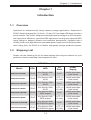
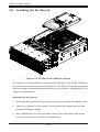
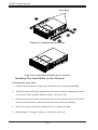
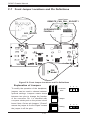
Chapter 1: Introduction
Chapter 1
Introduction
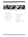
1-1 Overview
Optimized for enterprise-level heavy-capacity storage applications, Supermicro's
SC847 chassis features 36x (24 front + 12 rear) 3.5" hot-swap HDD bays used as a
server chassis. The SC847 design provides high-density storage in a 4U form factor,
with high power efficiency, optimized HDD signal trace routing and improved HDD
carrier design to dampen vibration and maximize performance. Equipped with a
1400W (Gold Level) high-efficiency redundant power supply and five hot-plug redundant cooling fans, the SC847 is a reliable, high-quality storage workhorse system.
1-2 Shipping List
Please visit the following link for the latest shiping lists and part numbers for your
particular chassis model http://www.supermicro.com/
SC847 Chassis
CPU
HDD
I/O
Slots
Power
Supply
SC847A-R1400LPB
DP/UP
36x (Server) SAS/
SATA
7x LP
1400W redundant
(Gold Level)
SC847A-R1400UB
DP/UP
36x (Server) SAS/
SATA
4x FF + 3
LP (UIO)
1400W redundant
(Gold Level)
SC847E1-R1400LPB
DP/UP
36x (Server) SAS/
SATA
7x LP
1400W redundant
(Gold Level)
SC847E1-R1400UB
DP/UP
36x (Server) SAS/
SATA
4x FF + 3
LP (UIO)
1400W redundant
(Gold Level)
SC847E2-R1400LPB
DP/UP
36x (Server) SAS/
SATA support
7x LP
1400W redundant
(Gold Level)
SC847E2-R1400UB
DP/UP
36x (Server) SAS/
SATA support
4x FF + 3
LP (UIO)
1400W redundant
(Gold Level)
SC847E26-R1400LPB
DP/UP
36x (Server) SAS/
SATA SAS2 support
7x LP
1400W redundant
(Gold Level)
SC847E26-R1400UB
DP/UP
36x (Server) SAS/
SATA SAS2 support
4x FF + 3
LP (UIO)
1400W redundant
(Gold Level)
Model
1-1
SC847 Chassis Manual
1-3 Where to get Replacement Components
Though not frequently, you may need replacement parts for your system. To ensure the highest level of professional service and technical support, we strongly
recommend purchasing exclusively from our Supermicro Authorized Distributors/
System Integrators/Resellers. A list of Supermicro Authorized Distributors/System
Integrators/Resellers can be found at: http://www.supermicro.com. Click the Where
to Buy link.
1-2
Chapter 1: Introduction
1-4 Contacting Supermicro
Headquarters
Address:
Super Micro Computer, Inc.
980 Rock Ave.
San Jose, CA 95131 U.S.A.
Tel:
+1 (408) 503-8000
Fax:
+1 (408) 503-8008
Email:
[email protected] (General Information)
[email protected] (Technical Support)
Web Site:
www.supermicro.com
Europe
Address:
Super Micro Computer B.V.
Het Sterrenbeeld 28, 5215 ML
's-Hertogenbosch, The Netherlands
Tel:
+31 (0) 73-6400390
Fax:
+31 (0) 73-6416525
Email:
[email protected] (General Information)
[email protected] (Technical Support)
[email protected] (Customer Support)
Asia-Pacific
Address:
Super Micro Computer, Inc.
4F, No. 232-1, Liancheng Rd.
Chung-Ho 235, Taipei County
Taiwan, R.O.C.
Tel:
+886-(2) 8226-3990
Fax:
+886-(2) 8226-3991
Web Site:
www.supermicro.com.tw
Technical Support:
Email:
[email protected]
Tel: 886-2-8226-1900
1-3
SC847 Chassis Manual
1-5 Returning Merchandise for Service
A receipt or copy of your invoice marked with the date of purchase is required before any warranty service will be rendered. You can obtain service by calling your
vendor for a Returned Merchandise Authorization (RMA) number. When returning
to the manufacturer, the RMA number should be prominently displayed on the
outside of the shipping carton, and mailed prepaid or hand-carried. Shipping and
handling charges will be applied for all orders that must be mailed when service
is complete.
For faster service, RMA authorizations may be requested online (http://www.
supermicro.com/support/rma/).
Whenever possible, repack the chassis in the original Supermicro carton, using the
original packaging material. If these are no longer available, be sure to pack the
chassis securely, using packaging material to surround the chassis so that it does
not shift within the carton and become damaged during shipping.
This warranty only covers normal consumer use and does not cover damages incurred in shipping or from failure due to the alteration, misuse, abuse or improper
maintenance of products.
During the warranty period, contact your distributor first for any product problems.
1-4
Chapter 2: System Safety
Chapter 2
System Safety
2-1 Overview
This chapter provides a quick setup checklist to get your chassis up and running.
Following the steps in order given should enable you to have your chassis set up
and operational within a minimal amount of time. This quick setup assumes that you
are an experienced technician, famailiar with common concepts and terminology.
2-2 Warnings and Precautions
You should inspect the box the chassis was shipped in and note if it was damaged
in any way. If the chassis itself shows damage, file a damage claim with carrier
who delivered your system.
Decide on a suitable location for the rack unit that will hold that chassis. It should
be situated in a clean, dust-free area that is well venilated. Avoid areas where heat,
electrical noise and eletromagnetic fields are generated.
You will also need the system placed near at least one grounded power outlet. When
configured, the SC847 chassis includes one power supply. "R" models include a
redundant power supply and require two grounded outlets.
2-3 Preparing for Setup
The SC847 chassis includes a set of rail assemblies which includes mounting brackets and mounting screws you will need to install the systems into the rack. Please
read this manual in its entirety before you begin the installation procedure.
2-1
SC847 Chassis Manual
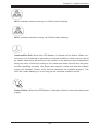
2-4 Electrical Safety Precautions
Basic electrical safety precautions should be followed to protect yourself from harm
and the SC847 from damage:
•Be aware of the locations of the power on/off switch on the chassis as well
as the room’s emergency power-off switch, disconnection switch or electrical
outlet. If an electrical accident occurs, you can then quickly remove power from
the system.
•Do not work alone when working with high voltage components.
•Power should always be disconnected from the system when removing or install-
ing main system components, such as the serverboard, memory modules (not
necessary for hot swappable drives). When disconnecting power, you should first
power down the system with the operating system and then unplug the power
cords from all the power supply modules in the system.
•When working around exposed electrical circuits, another person who is fa-
miliar with the power-off controls should be nearby to switch off the power, if
necessary.
•Use only one hand when working with powered-on electrical equipment. This
is to avoid making a complete circuit, which will cause electrical shock. Use
extreme caution when using metal tools, which can easily damage any electrical
components or circuit boards they come into contact with.
•Do not use mats designed to decrease electrostatic discharge as protection from
electrical shock. Instead, use rubber mats that have been specifically designed
as electrical insulators.
•The power supply power cord must include a grounding plug and must be
plugged into grounded electrical outlets.
•Serverboard battery: CAUTION - There is a danger of explosion if the onboard
battery is installed upside down, which will reverse its polarities This battery
must be replaced only with the same or an equivalent type recommended by
the manufacturer. Dispose of used batteries according to the manufacturer’s
instructions.
2-2
Chapter 2: System Safety
•Please handle used batteries carefully. Do not damage the battery in any way;
a damaged battery may release hazardous materials into the environment. Do
not discard a used battery in the garbage or a public landfill. Please comply
with the regulations set up by your local hazardous waste management agency
to dispose of your used battery properly.
2-5 General Safety Precautions
•Keep the area around the chassis clean and free of clutter.
•Place the chassis top cover and any system components that have been re-
moved away from the system or on a table so that they won’t accidentally be
stepped on.
•While working on the system, do not wear loose clothing such as neckties and
unbuttoned shirt sleeves, which can come into contact with electrical circuits or
be pulled into a cooling fan.
•Remove any jewelry or metal objects from your body, which are excellent metal
conductors that can create short circuits and harm you if they come into contact
with printed circuit boards or areas where power is present.
•After accessing the inside of the system, close the system back up and secure
it to the rack unit with the retention screws after ensuring that all connections
have been made.
2-6 System Safety
Electrostatic discharge (ESD) is generated by two objects with different electrical
charges coming into contact with each other. An electrical discharge is created to
neutralize this difference, which can damage electronic components and printed
circuit boards. The following measures are generally sufficient to neutralize this
difference before contact is made to protect your equipment from ESD:
•Do not use mats designed to decrease electrostatic discharge as protection from
electrical shock. Instead, use rubber mats that have been specifically designed
as electrical insulators.
•Use a grounded wrist strap designed to prevent static discharge.
•Keep all components and printed circuit boards (PCBs) in their antistatic bags
until ready for use.
2-3
SC847 Chassis Manual
•Touch a grounded metal object before removing any board from its antistatic
bag.
•Do not let components or PCBs come into contact with your clothing, which may
retain a charge even if you are wearing a wrist strap.
•Handle a board by its edges only; do not touch its components, peripheral chips,
memory modules or contacts.
•When handling chips or modules, avoid touching their pins.
•Put the serverboard and peripherals back into their antistatic bags when not
in use.
•For grounding purposes, make sure your computer chassis provides excellent
conductivity between the power supply, the case, the mounting fasteners and
the serverboard.
2-4
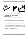
Chapter 3: System Interface
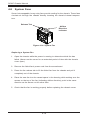
Chapter 3
System Interface
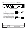
3-1 Overview
There are several LEDs on the control panel as well as others on the drive carriers
to keep you constantly informed of the overall status of the system as well as the
activity and health of specific components. Most SC847 models have two buttons
on the chassis control panel: A reset button and a power on/off switch. This chapter
explains the meanings of all LED indicators and the appropriate responses you
may need to take.
Figure 3-1: Control Panel
3-1
SC847 Chassis Manual
3-2 Control Panel Buttons
There are two push-buttons located on the left handle of the chassis. These are
(in order from top to bottom) a power on/off button and a reset button.
Power: The main power button is used to apply or remove power from the power
supply to the server system. Turning off system power with this button removes
the main power but keeps standby power supplied to the system. Therefore, you
must unplug system before servicing.
Reset: The reset button is used to reboot the system.
3-3 Control Panel LEDs
The control panel located on the left handle of the SC847 chassis has five LEDs.
These LEDs provide you with critical information related to different parts of the
system. This section explains what each LED indicates when illuminated and any
corrective action you may need to take.
Power: Indicates power is being supplied to the system's power supply units. This
LED should normally be illuminated when the system is operating.
HDD: Indicates IDE channel activity. SAS/SATA drive, and/or DVD-ROM drive
activity when flashing.
3-2
Chapter 3: System Interface
1
NIC1: Indicates network activity on GLAN1 when flashing.
2
NIC2: Indicates network activity on GLAN2 when flashing.
Overheat/Fan Fail: When this LED flashes, it indicates a fan failure. When continuously on (not flashing) it indicates an overheat condition, which may be caused
by cables obstructing the airflow in the system or the ambient room temperature
being too warm. Check the routing of the cables and make sure all fans are present and operating normally. You should also check to make sure that the chassis
covers are installed. Finally, verify that the heatsinks are installed properly. This
LED will remain flashing or on as long as the overheat condition exists.
!
Power Failure: When this LED flashes, it indicates a failure in the redundant power
supply.
3-3
SC847 Chassis Manual
3-4 Drive Carrier LEDs
The SC847 chassis uses SAS or SATA drives.
SAS/SATA Drives
Each SAS/SATA drive carrier has two LEDs.
•Blue:
Solid on = Drive is present and available.
Blinking = Drive is actively being accessed.
Each Serial ATA drive carrier has a blue LED. When illuminated in a solid
on state, this blue LED (on the front of the SAS/SATA drive carrier) indicates
drive activity. A connection to the SAS/SATA backplane enables this LED to
blink on and off when that particular drive is being accessed.
•Red:
Solid on = Drive failure
Blinking = RAID activity
When the red LED is blinking, it indicates that the system is either building,
initializing or rebuilding RAID.
SCSI Drives
This chassis does not support SCSI drives at this time.
3-4
Chapter 4: Chassis Setup and Maintenance
Chapter 4
Chassis Setup and Maintenance
4-1 Overview
This chapter covers the steps required to install components and perform maintenance on the chassis. The only tool you will need to install components and perform
maintenance is a Phillips screwdriver. Print this chapter to use as a reference while
setting up your chassis.
!
!
Review the warnings and precautions listed in the manual before
setting up or servicing this chassis. These include information in
Chapter 2: System Safety and the warnings/precautions listed in the
setup instructions.
Safety Warning: Before performing any chassis setup or maintenance, it is recommended that the chassis be removed from the rack
and placed on a stable bench or table. For instructions on how to
uninstall the chassis from the rack, refer to Chapter 5 Rack Installation in this manual.
4-1
SC847 Chassis Manual
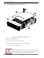
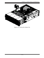
4-2 Removing the Chassis Cover
3
2
12
2
12
Figure 4-1: Removing the Chassis Cover
Removing the Chassis Cover
1. Unplug the chassis from any power source
2. Remove the screws securing the cover to the chassis.
3. Lift the cover up and off the chassis.
!
Warning: Except for short periods of time, do NOT operate the
server without the cover in place. The chassis cover must be in
place to allow proper airflow and prevent overheating.
4-2
Chapter 4: Chassis Setup and Maintenance
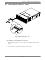
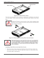
4-3 Installing Removable Hard Drives
2
1
Figure 4-2: Removing Hard Drive
Removing Hard Drive Carriers from the Chassis
1. Press the release button on the drive carrier. This extends the drive carrier
handle.
2. Use the handle to pull the drive carrier out of the chassis.
4-3
SC847 Chassis Manual
Dummy Drive
Drive Carrier
Figure 4-3: Chassis Drive Carrier
The drives are mounted in drive carriers to simplify their installation and removal
from the chassis. These carriers also help to promote proper airflow for the drive
bays.
!
Warning: Except for short periods of time (while swapping hard
drives), do not operate the server with the drives removed from
the chassis drive bays.
1
1
Figure 4-4: Removing the Dummy Drive from the Carrier
!
Warning! Enterprise level hard disk drives are recommended
for use in Supermicro chassis and servers. For information on
recommended HDDs, visit the Supermicro Web site at http://
www.supermicro.com/products/nfo/files/storage/SAS-1-CompList-110909.pdf
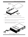
Installing a Hard Drive to the Hard Drive Carrier
1. Remove the two screws securing the dummy drive to the drive carrier and
remove the dummy drive. Place the hard drive carrier on a flat surface such
as a desk, table or work bench.
4-4
Chapter 4: Chassis Setup and Maintenance
SAS/SATA
Hard Drive
4
4
Drive Carrier
Figure 4-5: Installing the Hard Drive into the Carrier
2. Slide the hard drive into the carrier with the printed circuit board side facing
down.
3. Carefully align the mounting holes in both the drive carrier and the hard drive.
4. Secure the hard drive to the carrier using six screws.
5. Replace the drive tray into the chassis. Make sure to close the drive carrier
handle to lock the drive carrier into place.
5
Figure 4-6: Installing the Hard Drive
4-5
SC847 Chassis Manual
4-4 Installing Optional Fixed Hard Drives
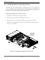
The SC847 chassis includes brackets for installing either one 3.5" fixed hard drive,
or two 2.5" fixed hard drives within the chassis. Each chassis can accomodate up
to two internal drive trays supporting up to two 3.5" hard drives or up to four 2.5"
hard drives. The tray part number is MCP-220-84701-0N.
Installing Fixed HDDs into the SC847 Chassis
1. Disconnect the chassis from any power source.
2. Remove the chassis cover as described in Section 4-2.
3. Remove the screw securing the motherboard node tray to the chassis.
4. Slide back the motherboard node tray to reveal the HDD mounting location on
the floor of the chassis.
Fixed HDD
Mounting
Location
13
14
Figure 4-7: Sliding Back the Motherboard Node Tray
4-6
Chapter 4: Chassis Setup and Maintenance
Figure 4-8: Installing Single and Dual Hard Drives and the Bracket
Installing a 3.5" Single Hard Drive into the Bracket
1. Align the four round washers and four screws with the holes in the hard drive
and the holes in the bracket.
2. Secure the hard drive to the bracket using the screws and washers provided.
3. See the instructions below for installing the bracket onto the chassis.
Installing Dual 2.5" Hard Drives into the Bracket
1. Align the eight external tooth washers and eight screws with the holes in the
hard drive and the holes in the bracket.
2. Secure the hard drive to the bracket using the screws and washers provided.
3. See the instructions below for installing the bracket onto the chassis.
Installing the Bracket onto the Chassis
1. Align the holes in the bracket with the chassis standoffs.
2. Secure the bracket using the screw provided as shown in Figure 4-10.
4-7
SC847 Chassis Manual
15
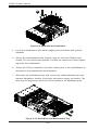
Figure 4-9: Motherboard Installation
4. Lay the motherboard on the chassis aligning the permanent and optional
standoffs
5. Secure the motherboard to the chassis using the rounded, Phillips head
screws. Do not exceed eight pounds of torque per square inch when tightening down the motherboard.
6. Secure the CPU(s), heatsinks, and other components to the motherboard as
described in the motherboard documentation.
7. Slide back the motherboard tray and connect the cables between the motherboard, backplane, chassis, front panel, and power supply, as needed. The
fans may be temporarily removed to allow access to the backplane ports.
17
Figure 4-10: Slide Back the Motherboard Tray
4-8
Flat head
Pan head
6-32 x 5 mm
6-32 x 5 mm
Chapter 4: Chassis Setup and Maintenance
[0.197]
[0.197]
DVD-ROM, CD-ROM, and FLOPPY DRIVE
4-5 Installing the Motherboard
Permanent and Optional Standoffs
Flat head
Round head
Pan head
6-32 x 5 mm
M3 x 5 mm
6-32 x 5 mm
[0.197]
[0.197] and
Standoffs prevent short circuits by [0.197]
securing space between
the motherboard
Round h
M2.6 x 5
[0.19
the chassis surface. The SC847 chassis includes permanent standoffs in locations
RAIL
used by most motherboards. These standoffs accept the rounded Phillips head
screws included in the SC847 accessories packaging.
Some motherboards require additional screws for heatsinks, general components
Flat head
and/or non-standard security. Optional
standoffs are included
to these motherRound head
Flat head
x 4must
mm place the hexagonal
M4 x 4 mm screw through
boards. To use an optional standoff,M4
you
M5 x 12 mm[0.472]
[0.157]
[0.157]
the bottom the chassis and secure the screw with the hexagon nut (roundedWasher
side for M5
M/B STANDOFFS
up).
M/B standoff
6-32 to 6-32
M/B (CPU)
standoff
M5 to 6-32
Figure 4-11: Chassis Standoffs
Thumb screw
6-32 x 5 mm
[0.197]
Installing the Motherboard
1. Review the documentation that came with your motherboard. Become familiar
with component placement, requirements, precautions, and cable connections.
2. Open the chassis cover and remove the chassis from any power source.
3. As required by your motherboard, install standoffs in any areas that do not
have a permanent standoff. To do this:
A. Place a hexagonal standoff screw through the bottom the chassis.
B. Secure the screw with the hexagon nut (rounded side up).
4-9
1/U M/B sta
6-32 x 5 m
[0.197]
SC847 Chassis Manual
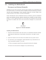
Add-on Card/Expansion Slot Setup
SC847: The chassis includes I/O slots for expansion cards. The number of cards
used depends on your chassis model.
SC847 LP Models: Provides seven low-profile expansion card slots.
SC847 UIO Models: Provides three full-height/full-length slots, three low-profile
slots and includes a universal expansion card.
Expansion
Card Slots
Figure 4-12: SC825 LP model
Expansion Slot Setup in LP (Low Profile) Chassis
SC847 chassis include slots for expansion cards. The number of cards you can use
depends on your chassis model and motherboard model.
Installing Expansion cards in SC847 LP (Low Profile) Chassis
1. Disconnect the power supply, lay the chassis on a flat surface, and open the
chassis cover.
2. Remove the screw holding the cover in place for each low profile expansion
card slot you want to use. Keep this screw for later use.
3. Connect the expansion cards to the motherboard.
4. Secure each card to the chassis using the card's L-bracket and the screw
previously removed.
4-10
Chapter 4: Chassis Setup and Maintenance
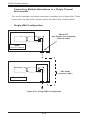
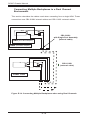
Expansion Slot Setup in U (Universal Output) Chassis
SC847 U model chassis accepts a slightly smaller "L" shaped motherboard to allow
for a universal expansion card. This universal output card allows the systems to
accept SAS, SCSI, IB, Ethernet, and other types of connections.
SC847 U chassis accepts three full-length, full-height add-on cards and the fourth
slot is used for the UI/O card. It includes a bracket that extends from the fan row to
the back of the chassis. This bracket provides support for the riser card.
Installing a Universal Input/Output Card in the SC847 U Model Chassis
1. Disconnect the power supply, lay the chassis on a flat surface, and open the
chassis cover.
2. Connect the universal input/output to the motherboard using the slots provided on the motherboard and the back panel.
3. Secure the card to the chassis using the four screws provided in the chassis
packaging.
The SC847 U model chassis includes three full-height/full-length slots and three
low-profile slots.
Installing Expansion Cards in the SC847 U Chassis
1. Disconnect the power supply, lay the chassis on a flat surface, and open the
chassis cover.
2. If you are using a universal input/output card, make sure it is installed before
continuing.
3. If you installing low profile add-on cards, remove the chassis air shroud.
4. Secure the card to the chassis using the four screws provided with the chassis packaging.
4-11
SC847 Chassis Manual
4-6 Installing the Air Shroud
Figure 4-13: Air Shroud for SC847LP Chassis
Air shrouds concentrate airflow to maximize fan efficiency. The SC847 chassis air
shroud does not require screws for its installation. The SC847 air shroud is designed
with removeable break-away tabs that allow the air shroud to be adjusted to fit a
variety of motherboards.
Installing the Air Shroud
1. Disconnect the chassis from any power source and remove the chassis cover.
2. Place the air shroud in the chassis. The air shroud fits behind the fans and
beside to the power supply.
3. After checking the fit of the air shroud, remove any break-away tabs necessary to ensure a proper fit with the motherboard.
4-12
Chapter 4: Chassis Setup and Maintenance
4-7 Checking the Server's Air Flow
Checking the Air Flow
1. Make sure there are no objects to obstruct airflow in and out of the server. In
addition, if you are using a front bezel, make sure the bezel's filter is replaced
periodically.
2. Do not operate the server without drives or drive trays in the drive bays. Use
only recommended server parts.
3. Make sure no wires or foreign objects obstruct air flow through the chassis. Pull
all excess cabling out of the airflow path or use shorter cables.
The control panel LEDs inform you of system status. See “Chapter 3: System
Interface” for details on the LEDs and the control panel buttons.
In most cases, the chassis power supply and fans are pre-installed. If you need to
install fans continue to the Systems Fan section of this chapter. If the chassis will be
installed into a rack, continue to the next chapter for rack installation instructions
4-13
SC847 Chassis Manual
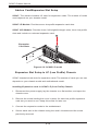
4-8 System Fans
Seven hot-swappable, heavy-duty fans provide cooling for the chassis. These fans
circulate air through the chassis thereby lowering the chassis internal temperature.
Release Tab
Airflow
Direction
Indicator
Figure 4-14: System Fan
Replacing a System Fan
1. Open the chassis while the power is running to determine which fan has
failed. (Never run the server for an extended period of time with the chassis
cover open.)
2. Remove the failed fan's power cord from the serverboard.
3. Press the fan release tab to lift the failed fan from the chassis and pull it
completely out of the chassis.
4. Place the new fan into the vacant space in the housing while making sure the
arrows on the top of the fan (indicating airflow direction) point in the same
direction as the arrows on the other fans.
5. Check that the fan is working properly before replacing the chassis cover.
4-14
Chapter 4: Chassis Setup and Maintenance
Figure 4-15: Placing the System Fan
4-15
SC847 Chassis Manual
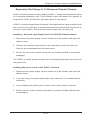
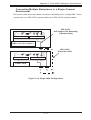
4-9 Power Supply
The SC847 chassis has a 1400 Watt high-efficiency redundant power supply. This
power supply is auto-switching capable. This enables it to automatically sense and
operate at a 100v to 240v input voltage. An amber light will be illuminated on the
power supply when the power is off. An illuminated green light indicates that the
power supply is operating.
Redundant power supplies are hot-swappable, and can be changed without powering down the system. New units can be ordered directly from Supermicro (see
contact information in the Preface).
Release Tab
Figure 4-16: Power Supply Release Tab
Changing the Power Supply:
1. If your chassis includes a redundant power supply (at least two power modules), you can leave the server running and remove only one power supply. If
your server has only one power supply, you must power down the server and
unplug the power cord.
2. Push the release tab (on the back of the power supply) as illustrated.
3. Pull the power supply out using the handle provided.
4. Replace the failed power module with the same model.
5. Push the new power supply module into the power bay until you hear a click.
6. Plug the AC power cord back into the module and power up the server.
4-16
Safety Information and Technical Specifications
Chapter 5
Cascading Configurations
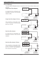
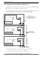
5-1 Cascading Configuration Overview
The SC847 chassis backplanes can be configured in a variety of combinations for
different applications. The following sections will provide connectivity configuration
options specific to your system.
5-2 Parallel Connectivity for Performance
The following configuration increases the SC847's performance capabilities by
utilizing parallel connectivity with SAS or SATA hard drives and a single expander
backplane.
+
WWN
+
1
BAR CODE
3
SEC_MODE4
+
+
C
1
J1
1
A
FANFAIL1
REMOTE_FAN_FAIL_SCOKET
WWN
C
+
GND
A
3
PRI_MODE4
A
12V_LED 5V_LED
C
A
C
1
2
OVERHEATFAIL1
2
+
+5V
1
+
+
+
Chassis SC847-EL1
+
GND
+12V
+
+
BUZZER_ENB1
SAS826EL
+
+12V
GND
GND
+5V
+12V
GND
GND
REV 1.02
+5V
DESIGNED IN USA
SAS-826EL
J0
RAID Cards
CBL-0281L
BUZZER_ENB1
REMOTE_FAN_FAIL_SOCKET1
OVERHEATFAIL1
SEC_I2C1
SEC_J2
SEC_IPMI1
SEC_J1
A
J2
SEC_J0
SEC_MODE1
BUZZER1
CBL-0352L-LP
C
A
C
FANFAIL1
PRI_J2
PRI_J1
PRI_J0
PRI_IPMI1
PRI_I2C1
J0
L1
WWN
SAS846EL2
REV 1.01
BAR CODE
DESIGNED IN USA
S_J1
WWN
SEC_EXP1
SEC_FLASH1
PRI_FLASH1
PRI_EXP1
P_J1
1J24
R227
EC22
2
A
CA
C
5V_LED1
J25
2
PWR5
EC20
+12V
GND
GND
+5V
+12V
GND
GND
PWR3
+12V
+5V
GND
GND
+5V
+12V
GND
GND
PWR1
EC8
+12V
+5V
GND
GND
+
+5V
+
PWR6
FAN2
PWR4
+12V
GND
GND
+5V
PRI_MODE1
FAN1
PWR2
SAS-846EL
BUZZER_ENB1
REMOTE_FAN_FAIL_SOCKET1
OVERHEATFAIL1
A
C
A
C
FANFAIL1
SEC_I2C1
SEC_J2
SEC_IPMI1
SEC_J1
SEC_J0
PRI_J2
PRI_J1
PRI_J0
PRI_IPMI1
R199
SEC_MODE1
BUZZER1
R210
PRI_I2C1
Figure 5-1: Parallel Connectivity for Increased Performance
L1
WWN
SAS846EL2
REV 1.01
BAR CODE
DESIGNED IN USA
S_J1
WWN
SEC_EXP1
SEC_FLASH1
PRI_FLASH1
PRI_EXP1
P_J1
R227
EC22
A
CA
C
5V_LED1
J25
2
PWR5
EC20
+12V
GND
GND
+5V
PWR6
+12V
GND
GND
+5V
PWR3
+12V
GND
GND
+5V
+12V
GND
GND
PWR4
PWR1
EC8
+12V
+5V
GND
GND
+
FAN2
+5V
+
+12V
GND
GND
+5V
PRI_MODE1
FAN1
PWR2
5-1
SC847 Chassis Manual
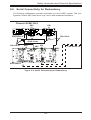
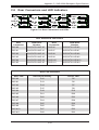
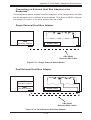
5-3 Parallel Connectivity for Performance with Mutiple
PCI Buses
The following configuration increases the SC847's performance capabilities using
multiple PCI buses. This configuration utilizes parallel connectivity with SAS or SATA
hard drives and a single expander backplane.
+
WWN
+
1
BAR CODE
3
SEC_MODE4
+
+
C
1
J1
1
A
FANFAIL1
REMOTE_FAN_FAIL_SCOKET
WWN
C
+
GND
A
3
PRI_MODE4
A
12V_LED 5V_LED
C
A
C
1
2
OVERHEATFAIL1
2
+
+5V
1
+
+
+
Chassis SC847-EL1
+
GND
+12V
+
+
BUZZER_ENB1
SAS826EL
+
+12V
GND
GND
+5V
+12V
GND
GND
REV 1.02
+5V
DESIGNED IN USA
SAS-826EL
J0
CBL-0281L
RAID Cards
RAID Cards
BUZZER_ENB1
REMOTE_FAN_FAIL_SOCKET1
OVERHEATFAIL1
SEC_I2C1
SEC_J2
SEC_IPMI1
SEC_J1
A
J2
SEC_J0
SEC_MODE1
BUZZER1
CBL-0352L-LP
C
A
C
FANFAIL1
PRI_J2
PRI_J1
PRI_J0
PRI_IPMI1
PRI_I2C1
J0
L1
WWN
SAS846EL2
REV 1.01
BAR CODE
DESIGNED IN USA
S_J1
WWN
SEC_EXP1
SEC_FLASH1
PRI_FLASH1
PRI_EXP1
P_J1
1J24
R227
EC22
2
A
CA
C
5V_LED1
J25
2
PWR5
EC20
+12V
GND
GND
+5V
+12V
GND
GND
PWR3
+12V
+5V
GND
GND
+5V
+12V
GND
GND
PWR1
EC8
+12V
+5V
GND
GND
+
+5V
+
PWR6
FAN2
PWR4
+12V
GND
GND
+5V
PRI_MODE1
FAN1
PWR2
SAS-846EL
BUZZER_ENB1
REMOTE_FAN_FAIL_SOCKET1
OVERHEATFAIL1
A
C
A
C
FANFAIL1
SEC_I2C1
SEC_J2
SEC_IPMI1
SEC_J1
SEC_J0
PRI_J2
PRI_J1
PRI_J0
PRI_IPMI1
R199
SEC_MODE1
BUZZER1
R210
PRI_I2C1
Figure 5-2: Parallel Connectivity Using Multiple PCI Buses
L1
WWN
SAS846EL2
REV 1.01
BAR CODE
DESIGNED IN USA
S_J1
WWN
SEC_EXP1
SEC_FLASH1
PRI_FLASH1
PRI_EXP1
P_J1
R227
EC22
A
CA
C
5V_LED1
J25
2
PWR5
EC20
+12V
GND
GND
+5V
PWR6
+12V
GND
GND
+5V
PWR3
+12V
GND
GND
+5V
+12V
GND
GND
PWR4
PWR1
EC8
+12V
+5V
GND
GND
+
FAN2
+5V
+
+12V
GND
GND
+5V
PRI_MODE1
FAN1
PWR2
5-2
Safety Information and Technical Specifications
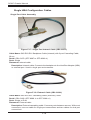
5-4 Serial Connectivity for Increased Capacity
The following configuration increases the SC847's capacity. This configuration
utilizes SAS or SATA hard drives and a single expander backplane.
+
WWN
+
1
BAR CODE
3
SEC_MODE4
+
+
C
1
J1
1
A
FANFAIL1
REMOTE_FAN_FAIL_SCOKET
WWN
C
+
GND
A
3
PRI_MODE4
A
12V_LED 5V_LED
C
A
C
1
2
OVERHEATFAIL1
2
+
+5V
1
+
+
+
Chassis SC847-EL1
+
GND
+12V
+
+
BUZZER_ENB1
SAS826EL
+
+12V
GND
GND
+5V
+12V
GND
GND
REV 1.02
+5V
DESIGNED IN USA
SAS-826EL
J0
RAID Cards
BUZZER_ENB1
REMOTE_FAN_FAIL_SOCKET1
OVERHEATFAIL1
SEC_I2C1
SEC_J2
SEC_IPMI1
SEC_J1
A
J2
SEC_J0
SEC_MODE1
BUZZER1
CBL-0351L-LP
CBL-0281L
C
A
C
FANFAIL1
PRI_J2
PRI_J1
PRI_J0
PRI_IPMI1
PRI_I2C1
J0
L1
WWN
SAS846EL2
REV 1.01
BAR CODE
DESIGNED IN USA
S_J1
WWN
SEC_EXP1
SEC_FLASH1
PRI_FLASH1
PRI_EXP1
P_J1
1J24
R227
EC22
2
A
CA
C
5V_LED1
J25
2
PWR5
EC20
+12V
GND
GND
+5V
+12V
GND
GND
PWR3
+12V
+5V
GND
GND
+5V
+12V
GND
GND
PWR1
EC8
+12V
+5V
GND
GND
+
+5V
+
PWR6
FAN2
PWR4
+12V
GND
GND
+5V
PRI_MODE1
FAN1
PWR2
SAS-846EL
BUZZER_ENB1
REMOTE_FAN_FAIL_SOCKET1
OVERHEATFAIL1
A
C
A
C
FANFAIL1
SEC_I2C1
SEC_J2
SEC_IPMI1
SEC_J1
SEC_J0
PRI_J2
PRI_J1
PRI_J0
PRI_IPMI1
R199
SEC_MODE1
BUZZER1
R210
PRI_I2C1
Figure 5-3: Serial Connectivity for Increased Capacity
L1
WWN
SAS846EL2
REV 1.01
BAR CODE
DESIGNED IN USA
S_J1
WWN
SEC_EXP1
SEC_FLASH1
PRI_FLASH1
PRI_EXP1
P_J1
R227
EC22
A
CA
C
5V_LED1
J25
2
PWR5
EC20
+12V
GND
GND
+5V
PWR6
+12V
GND
GND
+5V
PWR3
+12V
GND
GND
+5V
+12V
GND
GND
PWR4
PWR1
EC8
+12V
+5V
GND
GND
+
FAN2
+5V
+
+12V
GND
GND
+5V
PRI_MODE1
FAN1
PWR2
5-3
SC847 Chassis Manual
5-5 Serial Connectivity for Increased Capacity
The following configuration increases the SC847's capacity. This configuration
utilizes SAS or SATA hard drives and a single expander backplane.
+
WWN
+
1
BAR CODE
3
SEC_MODE4
+
+
C
1
J1
1
A
FANFAIL1
REMOTE_FAN_FAIL_SCOKET
WWN
C
+
GND
A
3
PRI_MODE4
A
12V_LED 5V_LED
C
A
C
1
2
OVERHEATFAIL1
2
+
+5V
1
+
+
+
Chassis SC847-EL1
+
GND
+12V
+
+
BUZZER_ENB1
SAS826EL
+
+12V
GND
GND
+5V
+12V
GND
GND
REV 1.02
+5V
DESIGNED IN USA
SAS-826EL
J0
CBL-0281L
RAID Cards
BUZZER_ENB1
REMOTE_FAN_FAIL_SOCKET1
OVERHEATFAIL1
SEC_I2C1
SEC_J2
SEC_IPMI1
SEC_J1
A
J2
SEC_J0
SEC_MODE1
BUZZER1
CBL-0351L-LP
C
A
C
FANFAIL1
PRI_J2
PRI_J1
PRI_J0
PRI_IPMI1
PRI_I2C1
J0
L1
WWN
SAS846EL2
REV 1.01
BAR CODE
DESIGNED IN USA
S_J1
WWN
SEC_EXP1
SEC_FLASH1
PRI_FLASH1
PRI_EXP1
P_J1
1J24
R227
EC22
2
A
CA
C
5V_LED1
J25
2
PWR5
EC20
+12V
GND
GND
+5V
+12V
GND
GND
PWR3
+12V
+5V
GND
GND
+5V
+12V
GND
GND
PWR1
EC8
+12V
+5V
GND
GND
+
+5V
+
PWR6
FAN2
PWR4
+12V
GND
GND
+5V
PRI_MODE1
FAN1
PWR2
SAS-846EL
BUZZER_ENB1
REMOTE_FAN_FAIL_SOCKET1
OVERHEATFAIL1
A
C
A
C
FANFAIL1
SEC_I2C1
SEC_J2
SEC_IPMI1
SEC_J1
SEC_J0
PRI_J2
PRI_J1
PRI_J0
PRI_IPMI1
R199
SEC_MODE1
BUZZER1
R210
PRI_I2C1
Figure 5-4: Serial Connectivity for Increased Capacity
L1
WWN
SAS846EL2
REV 1.01
BAR CODE
DESIGNED IN USA
S_J1
WWN
SEC_EXP1
SEC_FLASH1
PRI_FLASH1
PRI_EXP1
P_J1
R227
EC22
A
CA
C
5V_LED1
J25
2
PWR5
EC20
+12V
GND
GND
+5V
PWR6
+12V
GND
GND
+5V
PWR3
+12V
GND
GND
+5V
+12V
GND
GND
PWR4
PWR1
EC8
+12V
+5V
GND
GND
+
FAN2
+5V
+
+12V
GND
GND
+5V
PRI_MODE1
FAN1
PWR2
5-4
Safety Information and Technical Specifications
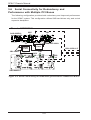
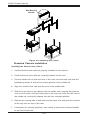
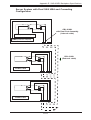
5-6 Serial Connectivity for Redundancy
The following configuration provides redundancy for the SC847 system. This configuration utilizes SAS hard drives only, and a dual expander backplane.
+
1
BAR CODE
3
SEC_MODE4
1
C
GND
A
+
3
PRI_MODE4
A
12V_LED 5V_LED
C
A
C
1
+
+
PRI
J1
A
2
OVERHEATFAIL1
2
C
1
FANFAIL1
REMOTE_FAN_FAIL_SCOKET
WWN
+
+5V
1
SEC
J1
WWN
+
+
+
+
Chassis SC847-EL2
+
GND
+12V
+
+
BUZZER_ENB1
SAS826EL
+
+12V
GND
GND
+5V
+12V
GND
GND
REV 1.02
+5V
DESIGNED IN USA
SAS-826EL2
SEC
J0
PRI
J0
CBL-0281L
RAID Cards
CBL-0281L
SEC
J2
BUZZER_ENB1
SEC_I2C1
SEC_J2
SEC_IPMI1
SEC_J1
SEC_J0
SEC
J0
PRI
J2
REMOTE_FAN_FAIL_SOCKET1
OVERHEATFAIL1
A
C
A
C
FANFAIL1
PRI_J2
PRI_J1
PRI_J0
PRI_IPMI1
SEC_MODE1
BUZZER1
PRI_I2C1
L1
PRI
J0
WWN
SAS846EL2
REV 1.01
BAR CODE
DESIGNED IN USA
S_J1
WWN
SEC_EXP1
SEC_FLASH1
PRI_FLASH1
PRI_EXP1
P_J1
1J24
R227
EC22
2
A
CA
C
5V_LED1
J25
2
PWR5
EC20
+12V
GND
GND
+5V
+12V
GND
GND
PWR3
+12V
+5V
GND
GND
+5V
+12V
GND
GND
PWR1
EC8
+12V
+5V
GND
GND
+
+5V
+
PWR6
FAN2
PWR4
+12V
GND
GND
+5V
PRI_MODE1
FAN1
PWR2
SAS-846EL2
BUZZER_ENB1
REMOTE_FAN_FAIL_SOCKET1
OVERHEATFAIL1
A
C
A
C
FANFAIL1
SEC_I2C1
SEC_J2
SEC_IPMI1
SEC_J1
SEC_J0
PRI_J2
PRI_J1
PRI_J0
PRI_IPMI1
R199
SEC_MODE1
BUZZER1
R210
PRI_I2C1
L1
Figure 5-5: Serial Connectivity for Redundancy
WWN
SAS846EL2
REV 1.01
BAR CODE
DESIGNED IN USA
S_J1
WWN
SEC_EXP1
SEC_FLASH1
PRI_FLASH1
PRI_EXP1
P_J1
R227
EC22
A
CA
C
5V_LED1
J25
2
PWR5
EC20
+12V
GND
GND
+5V
PWR6
+12V
GND
GND
+5V
PWR3
+12V
GND
GND
+5V
+12V
GND
GND
PWR4
PWR1
EC8
+12V
+5V
GND
GND
+
FAN2
+5V
+
+12V
GND
GND
+5V
PRI_MODE1
FAN1
PWR2
5-5
CBL-0352L-LP
SC847 Chassis Manual
5-6 Serial Connectivity for Redundancy and
Performance with Multiple PCI Buses
The following configuration provides both redundancy and improved performance
for the SC847 system. This configuration utilizes SAS hard drives only, and a dual
expander backplane.
Chassis SC847-EL2
SEC
J1
+
1
BAR CODE
3
SEC_MODE4
+
+
A
C
GND
A
+
PRI
J1
1
3
PRI_MODE4
A
12V_LED 5V_LED
C
A
C
1
2
OVERHEATFAIL1
2
C
1
FANFAIL1
REMOTE_FAN_FAIL_SCOKET
WWN
+
+5V
1
WWN
+
+
+
+
SAS-826EL2
+
GND
+12V
PRI
J0
CBL-0281L
+
+
BUZZER_ENB1
SAS826EL
+
+12V
GND
GND
+5V
+12V
GND
GND
REV 1.02
+5V
SEC
J0
DESIGNED IN USA
RAID
Card
RAID
Card
CBL-0281L
SEC
J2
BUZZER_ENB1
SEC_I2C1
SEC_J2
SEC_IPMI1
SEC_MODE1
BUZZER1
SEC_J1
SEC_J0
SEC
J0
CBL-0352L-LP
PRI
J2
REMOTE_FAN_FAIL_SOCKET1
OVERHEATFAIL1
A
C
A
C
FANFAIL1
PRI_J2
PRI_J1
PRI_J0
PRI_IPMI1
PRI_I2C1
L1
PRI
J0
WWN
SAS846EL2
REV 1.01
BAR CODE
DESIGNED IN USA
S_J1
WWN
SEC_EXP1
SEC_FLASH1
PRI_FLASH1
PRI_EXP1
P_J1
1J24
R227
EC22
2
A
CA
C
5V_LED1
J25
2
PWR5
EC20
+12V
GND
GND
+5V
+12V
GND
GND
PWR3
+12V
+5V
GND
GND
+5V
+12V
GND
GND
PWR1
EC8
+12V
+5V
GND
GND
+
+5V
+
PWR6
FAN2
PWR4
+12V
GND
GND
+5V
PRI_MODE1
FAN1
PWR2
SAS-846EL2
BUZZER_ENB1
REMOTE_FAN_FAIL_SOCKET1
OVERHEATFAIL1
A
C
A
C
FANFAIL1
SEC_I2C1
SEC_J2
SEC_IPMI1
SEC_J1
SEC_J0
PRI_J2
PRI_J1
PRI_J0
PRI_IPMI1
R199
SEC_MODE1
BUZZER1
R210
PRI_I2C1
L1
Figure 5-6: Serial Connectivity for Redundancy/Performance w/Multi-PCI Buses
WWN
SAS846EL2
REV 1.01
BAR CODE
DESIGNED IN USA
S_J1
WWN
SEC_EXP1
SEC_FLASH1
PRI_FLASH1
PRI_EXP1
P_J1
R227
EC22
A
CA
C
5V_LED1
J25
2
PWR5
EC20
+12V
GND
GND
+5V
PWR6
+12V
GND
GND
+5V
PWR3
+12V
GND
GND
+5V
+12V
GND
GND
PWR4
PWR1
EC8
+12V
+5V
GND
GND
+
FAN2
+5V
+
+12V
GND
GND
+5V
PRI_MODE1
FAN1
PWR2
5-6
Safety Information and Technical Specifications
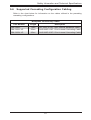
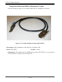
5-6 Supported Cascading Configuration Cabling
Refer to the chart below for information on the cables utilized in the preceding
cascading configurations.
Backplane Connectivity Cables
Length
Description
CBL-0281L
Part Number
75cm
SFF 8087 to SFF 8087 internal backplane cable.
CBL-0351L-LP
85cm
SAS 826EL1 BP 1-Port Internal Cascading Cable
CBL-0352L-LP
85cm
SAS 826EL2 BP 2-Port Internal Cascading Cable
5-7
SC847 Chassis Manual
Notes
5-8
Chapter 5: Rack Installation
Chapter 6
Rack Installation
6-1 Overview
This chapter provides a quick setup checklist to get your chassis up and running.
Following these steps in the order given should enable you to have the system
operational within a minimal amount of time.
6-2 Unpacking the System
You should inspect the box which the chassis was shipped in and note if it was
damaged in any way. If the chassis itself shows damage, you should file a damage
claim with the carrier who delivered it.
Decide on a suitable location for the rack unit that will hold your chassis. It should
be situated in a clean, dust-free area that is well ventilated. Avoid areas where
heat, electrical noise and electromagnetic fields are generated. The system needs
to be placed near a grounded power outlet. Be sure to read the Rack and Server
Precautions in the next section.
6-3 Preparing for Setup
The box your chassis was shipped in should include two sets of rail assemblies and
the mounting screws needed for installing the system into the rack. Also included
is an optional square hole to round hole converter bracket, for use in racks with
round mounting holes. Please read this section in its entirety before you begin the
installation procedure outlined in the sections that follow.
Choosing a Setup Location
•Leave enough clearance in front of the rack to enable you to open the front
door completely (~25 inches).
•Leave approximately 30 inches of clearance in the back of the rack to allow for
sufficient airflow and ease in servicing.
•This product is for installation only in a Restricted Access Location (dedicated
equipment rooms, service closets and similar environments).
6-1
SC847 Chassis Manual
!
Warning!
!
6-4 Warnings and Precautions
Rack Precautions
•Ensure that the leveling jacks on the bottom of the rack are fully extended to
the floor with the full weight of the rack resting on them.
•In single rack installations, stabilizers should be attached to the rack.
•In multiple rack installations, the racks should be coupled together.
•Always make sure that the rack is stable before extending a component from
the rack.
•You should extend only one component at a time - extending two or more simultaneously may cause the rack to become unstable.
General Server Precautions
•Review the electrical and general safety precautions that came with the components you are adding to your chassis.
•Determine the placement of each component in the rack before you install the
rails.
•Install the heaviest server components on the bottom of the rack first, and then
work upwards.
•Use a regulating uninterruptible power supply (UPS) to protect the server from
power surges, voltage spikes and to keep your system operating in case of a
power failure.
•Allow the hot plug hard drives and power supply modules to cool before touching them.
6-2
Chapter 5: Rack Installation
•Always keep the rack's front door and all panels and components on the servers
closed when not servicing to maintain proper cooling.
6-5 Rack Mounting Considerations
Ambient Operating Temperature
If installed in a closed or multi-unit rack assembly, the ambient operating temperature of the rack environment may be greater than the ambient temperature of the
room. Therefore, consideration should be given to installing the equipment in an
environment compatible with the manufacturer’s maximum rated ambient temperature (TMRA).
Reduced Airflow
Equipment should be mounted into a rack so that the amount of airflow required
for safe operation is not compromised.
Mechanical Loading
Equipment should be mounted into a rack so that a hazardous condition does not
arise due to uneven mechanical loading.
Circuit Overloading
Consideration should be given to the connection of the equipment to the power
supply circuitry and the effect that any possible overloading of circuits might have
on overcurrent protection and power supply wiring. Appropriate consideration of
equipment nameplate ratings should be used when addressing this concern.
Reliable Ground
A reliable ground must be maintained at all times. To ensure this, the rack itself
should be grounded. Particular attention should be given to power supply connections other than the direct connections to the branch circuit (i.e. the use of power
strips, etc.).
6-3
SC847 Chassis Manual
6-6 Rack Mounting Instructions
This section provides information on installing the chassis into a rack unit with the
rails provided. There are a variety of rack units on the market, which may mean
that the assembly procedure will differ slightly from the instructions provided. You
should also refer to the installation instructions that came with the rack unit you are
using. NOTE: This rail will fit a rack between 26.5" and 36.4" deep.
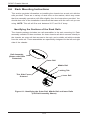
Identifying the Sections of the Rack Rails
The chassis package includes two rail assemblies in the rack mounting kit. Each
assembly consists of three sections: An inner chassis rail which secures directly to
the chassis, an outer rail that secures to the rack, and a middle rail which extends
from the outer rail. These assemblies are specifically designed for the left and right
side of the chassis.
Rail Assembly
(Shown with Rails
Retracted)
Outer Rail
Middle Rail
Locking Tab
This Side Faces
Outward
Inner Rail
Figure 6-1: Identifying the Outer Rail, Middle Rail and Inner Rails
(Left Rail Assembly Shown)
6-4
Chapter 5: Rack Installation
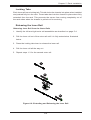
Locking Tabs
Each inner rail has a locking tab. This tab locks the chassis into place when installed
and pushed fully into the rack. These tabs also lock the chassis in place when fully
extended from the rack. This prevents the server from coming completely out of
the rack when when the chassis is pulled out for servicing.
Releasing the Inner Rail
Releasing Inner Rail from the Outer Rails
1. Identify the left and right outer rail assemblies as described on page 5-4.
2. Pull the inner rail out of the outer rail until it is fully extended as illustrated
below.
3. Press the locking tab down to release the inner rail.
4. Pull the inner rail all the way out.
5. Repeat steps 1-3 for the second outer rail.
1
12
13
14
Figure 6-2: Extending and Releasing the Inner Rail
6-5
SC847 Chassis Manual
Inner Rails
14
2
14
3
Figure 5-3: Installing the Inner Rails
Figure 6-4: Inner Rails Installed on the Chassis
Installing The Inner Rails on the Chassis
Installing the Inner Rails
1. Confirm that the left and right inner rails have been correctly identified.
2. Place the inner rail firmly against the side of the chassis, aligning the hooks
on the side of the chassis with the holes in the inner rail.
3. Slide the inner rail forward toward the front of the chassis until the rail clicks
into the locked position, which secures the inner rail to the chassis.
4. Secure the inner rail to the chassis with the screws provided.
5. Repeat steps 1 through 4 above for the other inner rail.
6-6
Chapter 5: Rack Installation
1
L-min=676.00(26.61")(outer rail)
12
14
21D01
13
Figure 6-5: Extending and Releasing the Outer Rails
Installing the Outer Rails on the Rack
Installing the Outer Rails
1. Press upward on the locking tab at the rear end of the middle rail.
2. Push the middle rail back into the outer rail.
3. Hang the hooks of the front of the outer rail onto the slots on the front of
the rack. If necessary, use screws to secure the outer rails to the rack, as
illustrated above.
4. Pull out the rear of the outer rail, adjusting the length until it fits within the
posts of the rack.
5. Hang the hooks of the rear portion of the outer rail onto the slots on the rear
of the rack. If necessary, use screws to secure the rear of the outer rail to the
rear of the rack.
6. Repeat steps 1-5 for the remaining outer rail.
6-7
SC847 Chassis Manual
Ball-Bearing
Shuttle
Figure 6-6: Installing into a Rack
Standard Chassis Installation
Installing the Chassis into a Rack
1. Confirm that the inner rails are properly installed on the chassis.
2. Confirm that the outer rails are correctly installed on the rack.
3. Pull the middle rail out from the front of the outer rail and make sure that the
ball-bearing shuttle is at the front locking position of the middle rail.
4. Align the chassis inner rails with the front of the middle rails.
5. Slide the inner rails on the chassis into the middle rails, keeping the pressure
even on both sides, until the locking tab of the inner rail clicks into the front of
the middle rail, locking the chassis into the fully extended position.
6. Depress the locking tabs of both sides at the same time and push the chassis
all the way into the rear of the rack.
7. If necessary for security purposes, use screws to secure the chassis handles
to the front of the rack.
6-8
Chapter 5: Rack Installation
Optional Quick Installation Method
The following quick installation method may be used to install the chassis onto a
rack.
Installing the Chassis into a Rack
1. Install the whole rail assembly onto the rack as described on page 5-7.
2. Release the inner rail without retracting the middle rail.
3. Install the inner rails on the chassis as previously described on page 5-6.
4. Install the chassis onto the middle rail as described in the previous section.
6-9
SC847 Chassis Manual
Adapters for Round and Threaded Hole Racks
The SC847 chassis includes adapter brackets for those customers using round hole
racks or racks with threaded holes size M5 or larger.
Installing the Adapter Bracket
1. Place the hooks of the front of the outer rail into the square holes of one of
the adapter brackets.
2. Place the hooks of the rear of the outer rail into the square holes of a second
adapter bracket.
3. Adjust the length of the outer rail to fit within the rack uprights.
4. Secure the front adapter bracket to the front of the rack using the screws
recommended by the rack manufacturer.
5. Secure the rear adapter bracket to the rear of the rack in the same manner.
6-10
Appendix A: Chassis Cables
Appendix A
SC847 Cables and Hardware
A-1 Overview
This appendix lists supported cables for your chassis system. It only includes the
most commonly used components and configurations. For more compatible cables,
refer to the manufacturer of the motherboard you are using and our Web site at:
www.supermicro.com.
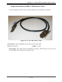
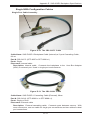
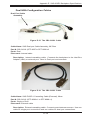
A-2 Cables Included with SC847 Chassis (SAS/SATA)
SC847
Part #
Type
Length
Description
CBL-0088L
Cable
9"
Seven each, 10.5", 4-pin middle fan
power extension (PWM)
CBL-0087
Ribbon,
Round
20"
16-pin to 16-pin ribbon cable for
control panel
Two each, regional power cords
CBL-0160L-
Cable
6'
CBL-0217L
Cable
22cm
A-1
16-pin control panel converter cable
SC847 Chassis Manual
A-3 Compatible Cables
These cables are compatible with the SC847 Chassis.
Alternate SAS/SATA Cables
Some compatible motherboards have different connectors. If your motherboard
has only one SAS connector that the SAS/SATA cables must share, use one of the
following cables. These cables must be purchased separately.
Cable Name: SAS Cable
Quantity: 1
Part #: CBL-0175L
Alt. Name: "Big Four"
Description: This cable has one SFF-8484 (32-pin) connector on one end and
four SAS connectors (7 pins each) at the other. This cable connects from the host
(motherboard or other controller) to the backplane SAS hard drive port.
Cable Name: SAS Cable
Quantity: 1
Part #: CBL-0116
Alt. Name: iPass or "Small Four"
Description: This cable has one iPass (SFF-8087/Mini-SAS) connector (36-pin) at
one end and four SAS connectors on one end. This cable connects from the host
(motherboard or other controller) to the backplane SAS hard drive port.
A-2
Appendix A: Chassis Cables
Extending Power Cables
Although Supermicro chassis are designed with to be efficient and cost-effective,
some compatible motherboards have power connectors located in different areas.
To use these motherboards you may have to extend the power cables to the mother
boards. To do this, use the following chart as a guide.
Power Cable Extenders
Number of Pins
Cable Part #
Length
24-pin
CBL-0042
7.9” (20cm)
20-pin
CBL-0059
7.9” (20cm)
8-pin
CBL-0062
7.9” (20cm)
4-pin
CBL-0060
7.9” (20cm)
Front Panel to the Motherboard
The SC847 chassis includes a cable to connect the chassis front panel to the
motherboard. If your motherboard uses a different connector, use the following list
to find a compatible cable.
Front Panel to Motherboard Cable (Ribbon Cable)
Number of Pins
(Front Panel)
Number of Pins
(Motherboard
Cable Part #
16-pin
16-pin
CBL-0049
16-pin
20-pin
CBL-0048
20-pin
20-pin
CBL-0047
16-pin
various*
CBL-0068
20-pin
various*
CBL-0067
* Split cables: Use these cable if your motherboard requires several different connections from the front panel.
A-3
SC847 Chassis Manual
A-4 Chassis Screws
The accessory box includes all the screws needed to set up your chassis. This
section lists and describes the most common screws used. Your chassis may not
require all the parts listed.
M/B
HARD DRIVE
Flat head
6-32 x 5 mm
[0.197]
Pan head
6-32 x 5 mm
[0.197]
DVD-ROM, CD-ROM, and FLOPPY DRIVE
Pan head
6-32 x 5 mm
[0.197]
Flat head
6-32 x 5 mm
[0.197]
Round head
M3 x 5 mm
[0.197]
Round head
M2.6 x 5 mm
[0.197]
RAIL
Flat head
M4 x 4 mm
[0.157]
Round head
M4 x 4 mm
[0.157]
Flat head
M5 x 12 mm[0.472]
Washer for M5
M/B STANDOFFS
M/B standoff
6-32 to 6-32
M/B (CPU)
standoff
M5 to 6-32
Thumb screw
6-32 x 5 mm
[0.197]
A-4
1/U M/B standoff
6-32 x 5 mm
[0.197]
Appendix B: Power Supply Specifications
Appendix B
SC847 Power Supply Specifications
This appendix lists power supply specifications for your chassis system.
SC847
1400W
MFR Part #
PWS-1K41P-1R
AC Input
1100W: 100 - 140V, 50 - 60Hz, 9.5 - 13.5A
1400W: 180 - 240V, 50 - 60Hz, 7.0 - 9.5A
DC Output
4A
+5V Standby
DC Output 92A @ 100-140V
+12V 116Ap @ 180-240V
With Distributor:
+5V
30A
+3.3V
24A
-12V
0.6Ap
B-1
SC847 Chassis Manual
Notes
B-2
Appendix C: SAS-826A Backplane Specifications
Appendix C
SAS-826A Backplane Specifications
To avoid personal injury and property damage, carefully follow all the safety steps
listed below when accessing your system or handling the components.
C-1 ESD Safety Guidelines
Electrostatic Discharge (ESD) can damage electronic components. To prevent damage to your system, it is important to handle it very carefully. The following measures
are generally sufficient to protect your equipment from ESD.
•Use a grounded wrist strap designed to prevent static discharge.
•Touch a grounded metal object before removing a component from the antistatic
bag.
•Handle the backplane by its edges only; do not touch its components, peripheral
chips, memory modules or gold contacts.
•When handling chips or modules, avoid touching their pins.
•Put the card and peripherals back into their antistatic bags when not in use.
C-2 General Safety Guidelines
•Always disconnect power cables before installing or removing any components
from the computer, including the SAS-826A backplane.
•Disconnect the power cable before installing or removing any cables from the
SAS-826A backplane.
•Make sure that the SAS-826A backplane is securely and properly installed on
the motherboard to prevent damage to the system due to power shortage.
C-1
SC847 Chassis Manual
C-3 An Important Note to Users
All images and layouts shown in this user's guide are based upon the latest PCB
Revision available at the time of publishing. The card you have received may or
may not look exactly the same as the graphics shown in this manual.
C-4 Introduction to the SAS-826A Backplane
The SAS-826A backplane has been designed to utilize the most up-to-date technology available, providing your system with reliable, high-quality performance.
This manual reflects SAS-826A Revision 1.00, the most current release available at
the time of publication. Always refer to the Supermicro Web site at www.supermicro.
com for the latest updates, compatible parts and supported configurations.
C-2
Appendix C: SAS-826A Backplane Specifications
C-5 Front Connectors and Jumpers
12
10
1 12
B
D53
C94
A
C
R325
A
D54
C
C88
C285
RP1
49
16
33
17 C86
C85
JP26
ACT2
ACT3
ACT1
ACT0
1
32
13
Y1
ACT7
ACT6
C45
+
C271 C272
R347
U24
+
ACT5
ACT4
14
C100
ACT8
ACT9
ACT10
ACT_IN#8-11
48
UPGRADE#1
R120
I2C#2
ACT11
1
JP47
JP95
C84
BAR CODE
U18
C107
F1
C32
JP10
BZ1
R94
C33
F3
JP13
F2
I2C#3
15
+
JP69
R376
JSM1
+
+
B
C3
+
1
A
4
C145
+
16
JP45
ALARM#2
R330
R336
C138
BUZZER RESET
JP45:OH#2 TEMP
OPEN:45
C
1-2:50
C
2-3:55
C
JP52
R141
1
JP25:OH#1 TEMP
OPEN:45
C
1-2:50
C
2-3:55
C
C
D36
C119
16
R200
R201
1
JP18
C5
17
JP84
SAS IN #1
C208 R226
R249
+
JP84:MODE
1-2:SGPIO
2-3:I2C
1
R337
+
C197
JP46
JP25
U41
U19
RT2
R257
1
C44
JSM2
UPGRADE#2
JSM3
4
+
R423
R422
R425
R424
C87
10
1
U2
SAS IN #2
JP78
D3
R6 R98
C215ALARM#1
C
A
R123
C132
R132
R126
REV 1.00
DESIGNED IN USA
SAS IN #3
C213
16
9072 RST
Y2
JP50 JP35
12
+
C201
R208
34
11
1
C198
18
SAS826A
C202
+
9071 RST
R63
C1
19
U40
22
23
33
ACT_IN#0-7
JP37I2C#1
+
Figure C-1: Front Connectors
Front Connectors
1. ACT_IN: JP26 and JP47
6. Power Connectors (4-pin): JP10,
JP13, and JP46
2. Chips: MG9071 and MG9072
7. iPass #1 JSM1
3. I2C Connector #1 JP37
8. iPass #2 JSM2
4. I2C Connector #2 JP95
9. iPass #3 JSM3
5. I2C Connector #3 JP52
10. Upgrade Connectors, JP69 and
JP78
C-3
SC847 Chassis Manual
C-6 Front Connector and Pin Definitions
#1. Activity LED Headers
The activity LED headers, designated JP26
and JP47, are used to indicate the activity
status of each SAS drive. The activity LED
headers are located on the front panel. For the
activity lead headers to work properly, connect
to them using a 10-pin LED cable. This is only
used when the activity LED is not supported
by the hard drive.
SAS Activity LED Header
Pin Definitions
Pin #
Definition
Pin #
Definition
1
ACT IN #0
6
ACT IN #4
2
ACT IN #1
7
ACT IN #5
3
ACT IN #2
8
ACT IN #6
4
ACT IN #3
9
ACT IN #7
5
Ground
10
Empty
SAS Activity LED Header
Pin Definitions
Pin #
Definition
Pin #
Definition
1
ACT IN #8
6
ACT IN #12
2
ACT IN #9
7
ACT IN #13
3
ACT IN #10
8
ACT IN #14
4
ACT IN #11
9
ACT IN #15
5
Ground
10
Empty
#2. MG9071 and MG9072 Chips
The MG9071 and MG9072 are enclosure
management chips that support the SES-2
controller and SES-2 protocols.
#3., #4., #5. I2C Connectors
The I C connectors, designated JP37, JP52,
and JP95, are used to communicate to HDD
to support SES-2 protocol. See the table on the
right for pin definitions.
I2C Connector
Pin Definitions
2
C-4
Pin#
Definition
1
Data
2
Ground
3
Clock
4
No Connection
Appendix C: SAS-826A Backplane Specifications
#6. Backplane Main Power Connectors
The 4-pin connectors, designated JP10,
JP13, and JP46 provide power to the
backplane. See the table on the right for
pin definitions.
#7., #8., #9. SAS Ports
The SAS ports are used to connect the SAS
drive cables. The 12 ports are designated
#0 - #11. Each port is also compatible with
SATA drives.
10. Upgrade Connectors
The upgrade connectors, designated JP69
and JP78, are used for manufacturer's diagnostic purposes only.
C-5
Backplane
Main Power
4-Pin Connector
Pin#
Definition
1
+12V
2 and 3
Ground
4
+5V
SC847 Chassis Manual
C-7 Front Jumper Locations and Pin Definitions
U40
+
B
B
D53
1
C94
C
D54
R325
A
C
C88
A
R423
R422
R425
R424
C87
C285
17 C86
R347
U24
C45
JP37I2C#1
ACT2
ACT3
+
Y1
ACT1
ACT_IN#8-11
C271 C272
C85
ACT0
ACT8
ACT9
ACT10
C84
ACT11
F1
C32
JP10
BZ1
33
C100
I2C#2
F2
I2C#3
+
JP26
JP95
U18
C107
R94
C33
F3
JP47
ACT7
ACT6
1
A
4
+
ACT5
ACT4
BAR CODE
JP45
ALARM#2
R330
R336
C138
BUZZER RESET
JP45:OH#2 TEMP
OPEN:45
C
1-2:50
C
2-3:55
C
48
16
JSM1
SAS IN #1
+
1
JP18
UPGRADE#1
ACT_IN#0-7
+
R141
Figure C-2: Front Jumpers
Explanation of Jumpers
To modify the operation of the backplane,
jumpers can be used to choose between
optional settings. Jumpers create shorts
between two pins to change the function
of the connector. Pin 1 is identified with
a square solder pad on the printed circuit
board. Note: On two pin jumpers, "Closed"
means the jumper is on and "Open" means
Connector
Pins
Setting
Jumper Settings
Jumper Settings
Note
JP35
Open: Default
Closed: Reset
MG9072 Chip Reset #1
JP50
Open: Default
Closed: Reset
MG9071 Chip Reset #2
C-6
3
2
1
3
2
1
Jumper
the jumper is off the pins.
Jumper
RP1
49
JP69
R376
C3
C
D36
R200
JP13
JP52
JP84
1
R201
C145
+
JP84:MODE
1-2:SGPIO
2-3:I2C
U19
JSM2
C119
+
JP18
JP84
JP25:OH#1 TEMP
OPEN:45
C
1-2:50
C
2-3:55
C
RT2
R337
C5
C197
JP25
U41
SAS IN #2
UPGRADE#2
JSM3
C208 R226
R249
+
JP46
C44
DESIGNED IN USA
SAS IN #3
C213
1
+
D3
R6 R98
U2
R120
+
JP35
JP78
R257
4
C215ALARM#1
C
A
R208
12
9072 RST
C201
+
REV 1.00
+
9071 RST
Y2
R63
C1
JP50
JP50 JP35
11
34
23
1
22
33
R123
C132
R132
R126
SAS826A
C202
C198
32
Appendix C: SAS-826A Backplane Specifications
I2C and SGPIO Modes and Jumper Settings
This backplane can utilize I2C or SGPIO. SGPIO is the default mode and can be
used without making changes to your jumpers. The following information details
which jumper must be configured to use SGPIO mode or restore your backplane
to I2C mode.
Jumper Settings: SGPIO (Default) and I2C
Jumper
JP84
SGPIO (Default) Setting
1-2: SGPIO mode enable
C-7
I2C Setting
C-3: I C mode enable
2
SC847 Chassis Manual
Front LED Indicators
U40
REV 1.00
22
R347
+
16
ACT_IN#0-7
+
Figure C-3: Front LEDs
Front Panel LEDs
State
Specification
D53
On
Indicates +5V power. Light is on during
normal operation.
D54
On
Indicates +12V power. Light is on during
normal operation.
C-8
RP1
33
ACT2
ACT3
ACT1
+
JP37I2C#1
R141
LED
C271 C272
Y1
ACT0
ACT_IN#8-11
C
C85
JP26
ACT8
ACT9
C84
ACT10
F1
C32
JP10
BZ1
ACT11
F2
I2C#3
+
C45
ACT7
ACT6
JP13
I2C#2
ACT5
ACT4
JP47
JP95
U18
C107
R94
F3
C33
+
1
A
4
C145
JP52
R330
R336
C119
+
BAR CODE
JP45
ALARM#2
A
49
17 C86
U24
C
D36
R200
R201
R337
C138
BUZZER RESET
JP45:OH#2 TEMP
OPEN:45
C
1-2:50
C
2-3:55
C
D54
R325
D54
48
C100
RT2
C3
+
1
JP18
C
C88
UPGRADE#1
JSM1
UPGRADE#2
JSM3
SAS IN #1
JSM2
SAS IN #2
SAS IN #3
C213
+
D53
A
JP69
R376
JP25:OH#1 TEMP
OPEN:45
C
1-2:50
C
2-3:55
C
C208 R226
C5
C197
B
C285
1
R249
+
JP46
D53
+
B
1
R120
+
1
JP84
U19
JP78
R257
4
JP84:MODE
1-2:SGPIO
2-3:I2C
C94
DESIGNED IN USA
C201
JP25
U41
R423
R422
R425
R424
C87
9072 RST
Y2
C44
U2
JP50 JP35
12
11
1
C198
+
D3
R6 R98
R63
C1
34
C215ALARM#1
C
A
R208
+
9071 RST
R123
C132
R132
R126
SAS826A
C202
23
33
32
Appendix C: SAS-826A Backplane Specifications
C-8 Rear Connectors and LED Indicators
C
D27
C
A
R181
A
FAIL#10
R176
ACT#10
C
D33
R182
SAS #8
SAS/SATA HHD #8
SAS #3
SAS/SATA HHD #3
SAS #9
SAS/SATA HHD #9
SAS #4
SAS/SATA HHD #4
SAS #10
SAS/SATA HHD #10
SAS #5
SAS/SATA HHD #5
SAS #11
SAS/SATA HHD #11
Rear LED Indicators
Hard Drive Activity
Failure LED
SAS #0
D12
D5
SAS #1
D13
D6
SAS #2
D14
D7
SAS #3
D15
D8
SAS #4
D18
D19
SAS #5
D21
D20
SAS #6
D22
D23
SAS #7
D24
D29
SAS #8
D25
D30
SAS #9
D26
D31
SAS #10
D27
D32
SAS #11
D28
D33
A
D31
R180
SAS/SATA HHD #2
FAIL#9
SAS #2
C
A
SAS/SATA HHD #7
ACT#9
SAS/SATA HHD #6
SAS #7
D26C
R175
SAS #6
SAS/SATA HHD #1
D32
SAS/SATA HHD #0
SAS #1
C-9
A
SAS Drive
Number
SAS #0
Rear LED
FAIL#11
A
Rear
Connector
C
A
R165
FAIL#6
C
A
R164
ACT#6
Rear SAS/SATA Connectors
SAS Drive
Number
D26
D31
J18
SAS
#9
Figure C-4: Rear Connectors and LEDs
Rear
Connector
R177
SAS
#10
D22
C
D8
D5
SAS #9
J18
D27
D32
J19
D29
R178
A
D23
J13
ACT#11
A
SAS #10
J19
D28
FAIL#7
C
R90
FAIL#3
A C
R88
A
D22
D23
A
R173
C
ACT#3
D15
R85
FAIL#0
AC
SAS
#6
ACT#7
C
D24
R96
D19 A
FAIL#4
D24
D29
D28
D33
J20
SAS
#11
C
A
R179
D30
SAS #11
J20
J15
SAS
#7
FAIL#8
R300
R298
R297
R299
AC
R95
ACT#4
R83
ACT#0
C
D12
SAS #7
J15
SAS #6
J13
C
A
Q33
D18
C
R87
J4
D25
D20
D6 A
FAIL#1
D15
D8
SAS
#3
R174
J17
SAS
#8
Q32
J9
SAS
#4
D25
D30
C
A
R149
SAS #8
J17
ACT#8
C
R150
FAIL#5
D18
D19
A
D13 A
SAS #3
J4
D21
#5
ACT#1
C
R84
SAS #4
J9
C
J11
SAS
ACT#5
D7
R89
D12
D5
J1
SAS
#0
SAS #5
J11
A
REV 1.00
J2
D21
D20
FAIL#2
SAS826A
D13
D6
R86
A C
#1
D14
SAS
C
#2
SAS #1
J2
SAS #0
J1
D14
D7
J3
SAS
ACT#2
SAS #2
J3
SC847 Chassis Manual
Notes
C-10
Appendix D: SAS-846A Backplane Specifications
Appendix D
SAS-846A Backplane Specifications
To avoid personal injury and property damage, carefully follow all the safety steps
listed below when accessing your system or handling the components.
D-1 ESD Safety Guidelines
Electrostatic Discharge (ESD) can damage electronic components. To prevent damage to your system, it is important to handle it very carefully. The following measures
are generally sufficient to protect your equipment from ESD.
•Use a grounded wrist strap designed to prevent static discharge.
•Touch a grounded metal object before removing a component from the antistatic
bag.
•Handle the backplane by its edges only; do not touch its components, peripheral
chips, memory modules or gold contacts.
•When handling chips or modules, avoid touching their pins.
•Put the backplane and peripherals back into their antistatic bags when not in
use.
D-2 General Safety Guidelines
•Always disconnect power cables before installing or removing any components
from the computer, including the backplane.
•Disconnect the power cable before installing or removing any cables from the
backplane.
•Make sure that the backplane is securely and properly installed on the motherboard to prevent damage to the system due to power shortage.
D-1
SC847 Chassis Manual
D-3 A Note to Users
All images and layouts shown in this user's guide are based upon the latest PCB
Revision available at the time of publishing. The card you have received may or
may not look exactly the same as the graphics shown in this manual.
D-4 Introduction to the SAS-846A Backplane
The SAS-846A backplane has been designed to utilize the most up-to-date technology available, providing your system with reliable, high-quality performance.
This manual reflects SAS-846A Revision 1.00, the most current release available at
the time of publication. Always refer to the Supermicro Web site at www.supermicro.
com for the latest updates, compatible parts and supported configurations.
D-2
Appendix D: SAS-846A Backplane Specifications
D-5 Front Connectors and Components
13
1
C359
C283
JP18
CH#20~23
JP106
U24
JSM6
+
49
C
A
D53
C A D54
C
R325
BZ1
C85
D64
C106
R128
R127
18
C44
C20
C149
R183
R185
R184
DESIGNED IN USA
#3
UPGRADE#1
+
C3
JP69
C19
#2
JSM1
CH#0~3
+
13
C119
ACT_IN#0-7
JP37
JP95
2
6
5
3
7
JP26
I2C#2
4
#1
17
3
R220
JP10 F5
17
MH12
4
1
1
FAN#2
MH13
FAN#4
JP60
JP64
+
C35
C261
C5
17
JP58
4
F6
1
0
1
JP13
4
D89
+
R405
R404
R403
#12
1
R218
17
17
C258
#18
JP63
C194
I2C#1
JP62
JP46
+5V
R305
MH14
FAN#3
C193
+
3
GND
+5V
3
MH15
C136
R168
C319
I2C#3
C285
GND
1
+12V
JP109
C202
GND
JP52
+
F20
GND
CA
JP84:MODE
1-2:SGPIO
2-3:I2C
12
1
4
JP110
+12V
10 11
R367
JP48
JP54
9
JP47
#13
C318
F19
1
R624
14
C201
+
ACT_IN#8-15
12 13 14 15
8
C241
F14
R217
JP61
15
JP108
FAN#1
C328
+
JP96
D36
#4
R167
23
A
+
C135
JP117
19
CH#4~7
JSM2
+
U91
C
+
Y1
R219
#19
18
22
C88
C84
I2C#6
20
21
R415
R414
R111
R112
R147
R148
R104
R344
19
C198
R591
R629
R623
JP116
17
1
+
ACT_IN#16-23
16
I2C#5
D3
R105
C89
12
R619
CA
U19
C271 C272
R113
JP50:9072#2 RESET
1-2: RESET
2-3: NO RESET
+
Y2
13
#14
C200
C A D51
C173
+
#10
JP50
R575
C204
13
U40
D49
R324
JP78
#20
C213
CA
#5
#9
C212
CA D47
C45
#15
C206
D45
+
JSM4
C229
16
JP35
A
JP25:OH#1 TEMP.
OPEN:45
C
1-2:50
C
2-3:55
C
C203
3
C337
JP97
JP98
JP99
JP100
+
CH#12~15
+
C324
1
+
JP105
JSM3
JP35:9072#1 RESET
1-2: RESET
2-3: NO RESET
1
R494
UPGRADE#3
JP115
#21
C329
R270
#16
JP97:FAN#1 SELECT
JP98:FAN#2 SELECT
JP99:FAN#3 SELECT
JP100:FAN#4 SELECT
1-2:WITH FAN
2-3:NO FAN
C199
+
11
1
C243
JSM5
R423
12
+
Y3
1
U63
C323
16
C197
+
R425
R424
12
1
#22
C325
+
U73
1
+
CH#8~11
U2
D113
+
C327
64
D116
10
1
#17
JP129:9072#3 RESET
1-2: RESET
2-3: NO RESET
JP25
C330
JP45:OH#2 TEMP.
OPEN:45
C
1-2:50
C
2-3:55
C
C282
3
+
JP45
JP107:OH#3 TEMP.
OPEN:45
C
1-2:50
C
2-3:55
C
#11
JP129
C326
+
JP107
3
1
1
1
BUZZER RESET
#23
17
F4
SAS846A
MH11
#0
Figure D-1: Front Components
Front Connectors and Components
1. Chip: MG9072
2. Upgrade Connectors: JP69, JP78 and JP115
3. ACT_IN: JP26, JP47, and JP108
4. I2C Connector #1 (JP37) and #2 (JP95)
5. I2C Connector #3 (JP52) and #4 (JP96)
6. I2C Connector #5 (JP116) and #6 (JP117)
7. Power Connectors (4-pin): JP10, JP13, JP46, JP48, JP109, and JP110
8. iPass Connector CH# 0-3, JSM1
9. iPass Connector CH# 4-7, JSM2
10. iPass Connector CH# 8-11, JSM3
11. iPass Connector CH# 12-15, JSM4
12. iPass Connector CH# 16-19, JSM5
13. iPass Connector CH# 20-23, JSM6
D-3
JP61:FAN#1 SELECT
JP62:FAN#2 SELECT
JP63:FAN#3 SELECT
JP64:FAN#4 SELECT
1-2:WITH FAN
2-3:NO FAN
REV: 1.00
SC847 Chassis Manual
D-6 Front Connector and Pin Definitions
1. MG9072 Chip
The MG9072 is an enclosure management
chip that supports the SES-2 controller and
SES-2 protocols.
2. Upgrade Connectors
The upgrade connectors are designated JP69,
JP78, and JP115 and are used for manufacturer's diagnostic purposes only.
3. Activity LED Header
The activity LED header, designated JP26,
JP47 and JP108, is used to indicate the activity status of each SAS drive. The Activity LED
Header is located on the front panel. For the
Activity LED Header to work properly, connect
using a 10-pin LED cable.
I2C Connector
Pin Definitions
4., 5., 6. I2C Connectors
The I2C Connectors, designated JP37, JP95,
JP52, JP96, JP116, and JP117, are used
to communicate to HDD to support SES-2
protocol. See the table on the right for pin
definitions.
Pin# Definition
1
Data
2
Ground
3
Clock
4
No Connection
7. Backplane Main Power Connectors
The 4-pin connectors, designated JP10, JP13,
JP46, JP48, JP109, and JP110, provide power
to the backplane. See the table on the right for
pin definitions.
D-4
Backplane
Main Power
4-Pin Connector
Pin#
Definition
1
+12V
2 and 3
Ground
4
+5V
Appendix D: SAS-846A Backplane Specifications
D-7 Front Jumper Locations and Pin Definitions
JP18
JP129
C359
BUZZER RESET
C283
JP18
CH#20~23
JP106
U24
JP107
3
1
JSM6
U73
49
1
3
JP35
JP50
JP50
#10
C88
C
A
D36
CA
D89
C
D53
C A D54
C
R325
BZ1
#4
+
C44
JSM2
C20
C149
R183
R185
R184
R167
C136
R168
JP84:MODE
1-2:SGPIO
2-3:I2C
DESIGNED IN USA
#3
R105
C89
+
UPGRADE#1
R367
JP69
C3
R624
+
Y2
C19
C229
R619
C241
C201
#2
#14
#20
A
D64
JP84
CH#4~7
R575
C204
D3
C106
R128
R127
Y1
C135
R415
R414
R111
R112
R147
R148
R104
R344
C198
U40
CA
+
#9
C213
C A D51
U19
C271 C272
R113
JP50:9072#2 RESET
1-2: RESET
2-3: NO RESET
+
JSM4
C212
D49
+
C45
CH#12~15
C206
CA
#5
+
#15
+
CA D47
R324
JSM3
JP78
C337
1
R494
UPGRADE#3
JP115
#21
C329
+
C173
C199
+
JP35:9072#1 RESET
1-2: RESET
2-3: NO RESET
1
JP97
JP98
JP99
JP100
JP35
JP97:FAN#1 SELECT
JP98:FAN#2 SELECT
JP99:FAN#3 SELECT
JP100:FAN#4 SELECT
1-2:WITH FAN
2-3:NO FAN
JSM5
D45
JP25:OH#1 TEMP.
OPEN:45
C
1-2:50
C
2-3:55
C
+
JP105
CH#8~11
C203
C197
+
R270
R423
#16
+
Y3
A
C282
C243
16
#22
C325
+
JP45:OH#2 TEMP.
OPEN:45
C
1-2:50
C
2-3:55
C
#11
U63
C323
R425
R424
+
JP45
C85
D113
+
C327
64
D116
+
#17
JP129:9072#3 RESET
1-2: RESET
2-3: NO RESET
U2
3
+
JP129
+
C330
JP25
1
#23
C326
JP97
JP98
JP99
JP100
JP107:OH#3 TEMP.
OPEN:45
C
1-2:50
C
2-3:55
C
JSM1
+
22
19
23
JP96
JP63
C194
1
JP37
JP62
3
7
#1
4
1
JP64
3
1
+
JP63
FAN#4
JP60
JP26
I2C#2
4
C35
C261
R220
#12
6
5
JP10 F5
C258
R305
MH13
2
C5
4
JP58
4
JP13
R218
3
1
FAN#2
0
1
F6
JP46
JP62
MH14
JP95
I2C#1
1
3
+5V
C285
GND
1
GND
+5V
#18
FAN#3
JP48
+12V
JP109
C202
GND
C193
+
+
F20
GND
+
I2C#3
C319
F19
MH15
#13
C318
4
JP110
+12V
JP47
JP52
F14
JP61
R217
JP54
10 11
ACT_IN#0-7
JP108
FAN#1
C328
1
9
R219
JP117
JP61
8
C119
20
21
18
R405
R404
R403
I2C#6
17
+
ACT_IN#8-15
12 13 14 15
C84
R591
R629
R623
16
I2C#5
#19
U91
ACT_IN#16-23
JP116
+
CH#0~3
C200
C324
+
F4
SAS846A
JP61:FAN#1 SELECT
JP62:FAN#2 SELECT
JP63:FAN#3 SELECT
JP64:FAN#4 SELECT
1-2:WITH FAN
2-3:NO FAN
JP64
MH12
REV: 1.00
MH11
#0
Figure D-2: Front Jumpers
Explanation of Jumpers
To modify the operation of the backplane,
jumpers can be used to choose between
optional settings. Jumpers create shorts
between two pins to change the function
of the connector. Pin 1 is identified with
a square solder pad on the printed circuit
board. Note: On two pin jumpers, "Closed"
means the jumper is on and "Open" means
the jumper is off the pins.
Connector
Pins
3
2
1
3
2
1
Jumper
Setting
Jumper Settings
Jumper
Jumper Setting
Notes
JP35
1-2: Reset
2-3: Normal (Default)
MG9072 Chip Reset #1
JP50
1-2: Reset
2-3: Normal (Default)
MG9072 Chip Reset #2
JP129
1-2: Reset
2-3: Normal (Default)
MG9072 Chip Reset #3
D-5
SC847 Chassis Manual
Fan Jumper Settings
This backplane can use up to four fans. To utilize each fan, you must configure
both jumpers as indicated below.
Fan Jumper Settings
Jumper
Jumper Settings
Note
JP61
1-2: With Fan (Default)
2-3: No Fan
FAN#1
JP97
1-2: With Fan (Default)
2-3: No Fan
FAN#1
JP62
1-2: With Fan (Default)
2-3: No Fan
FAN#2
JP98
1-2: With Fan (Default)
2-3: No Fan
FAN#2
JP63
1-2: With Fan (Default)
2-3: No Fan
FAN#3
JP99
1-2: With Fan (Default)
2-3: No Fan
FAN#3
JP64
1-2: With Fan (Default)
2-3: No Fan
FAN#4
JP100
1-2: With Fan (Default)
2-3: No Fan
FAN#4
I2C and SGPIO Modes and Jumper Settings
This backplane can utilize I2C or SGPIO. SGPIO is the default mode and can be
used without making changes to your jumper. The following information details
which jumper must be configured to use SGPIO mode or restore your backplane
to I2C mode.
SGPIO Setting (Default)
Jumper
JP84
SGPIO Jumper Setting (Default)
1-2
I2C Jumper Setting
2-3
D-6
Appendix D: SAS-846A Backplane Specifications
Front LED Indicators
A
D45
CA D47
D49
CA
C A D51
C
D3
CA
D36
A
D89
CA
C
A
JP25:OH#1 TEMP.
OPEN:45
C
1-2:50
C
2-3:55
C
+
JP25
U2
C359
BUZZER RESET
C283
JP18
CH#20~23
JP106
JP107
3
1
JP45
JP107:OH#3 TEMP.
OPEN:45
C
1-2:50
C
2-3:55
C
JP45:OH#2 TEMP.
OPEN:45
C
1-2:50
C
2-3:55
C
A
C282
U24
CH#8~11
#11
JSM6
U73
+
+
49
C323
1
1
A
D36
CA
D89
C
JP35
#10
JP50
C88
#4
C20
C149
R183
R185
R184
R167
C136
R168
JP84:MODE
1-2:SGPIO
2-3:I2C
DESIGNED IN USA
#3
R105
C89
+
UPGRADE#1
R575
R624
R367
JP69
C3
D64
+
C19
R619
C241
BZ1
D64
C201
#2
#14
#20
R325
C44
JSM2
C85
C229
C45
U40
#5
C
C106
R128
R127
C198
CH#4~7
#9
C213
Y2
C A D54
+
Y1
C135
R415
R414
R111
R112
R147
R148
R104
R344
#15
C212
D53
+
U19
C271 C272
R113
JP50:9072#2 RESET
1-2: RESET
2-3: NO RESET
+
JSM4
C206
A
+
C45
CH#12~15
+
C204
C
R324
+
3
JP97
JP98
JP99
JP100
+
JP78
C337
D3
C173
R494
UPGRADE#3
JP115
#21
CA
#5
JP35:9072#1 RESET
1-2: RESET
2-3: NO RESET
R270
R423
C199
C329
C243
#16
JP97:FAN#1 SELECT
JP98:FAN#2 SELECT
JP99:FAN#3 SELECT
JP100:FAN#4 SELECT
1-2:WITH FAN
2-3:NO FAN
JSM5
+
+
R425
R424
+
Y3
C A D51
C203
C197
+
U63
+
16
#22
C325
+
D49
C85
1
+
CA
U2
D113
C327
64
D116
CA D47
JP25
C330
3
+
JP129
C326
+
#17
JP129:9072#3 RESET
1-2: RESET
2-3: NO RESET
D45
JP25:OH#1 TEMP.
OPEN:45
C
1-2:50
C
2-3:55
C
+
JP105
JSM3
1
#23
JSM1
CH#0~3
C200
C324
+
+
18
22
19
23
JP96
F14
F6
3
R220
3
C5
JP13
JP10 F5
JP46
D89
4
1
1
F4
JP61:FAN#1 SELECT
JP62:FAN#2 SELECT
JP63:FAN#3 SELECT
JP64:FAN#4 SELECT
1-2:WITH FAN
2-3:NO FAN
REV: 1.00
#4
MH11
MH12
Failure in Fan #2
On
Failure in Fan #4
On
Alarm #1: Overheat/drive failure in Channel
1
On
On
Off
D54
Off
Alarm #2: Overheat/drive failure in Channel
2
Alarm #3: Overheat/ in Channel 3
+12V : Backplane power failure. Light is on
during normal operation.
#2
+
C119
R405
R404
R403
4
#3
+5V : Backplane power failure. Light is on
during normal operation.
C19
D53
0
DES
Failure in Fan #3
+
JP69
Specification
1-2:SGPIO
On
2-3:I2C
C3
R367
FAN#4
JP60
JP64
SAS846A
Failure in Fan #1
R105
C89
UPGRADE#1
R624
#1
+
#0
C20
D3
D36
7
JP26
FAN#2
C44
C149
R183
R185
R184
On
JP84:MODE
D51
R575
3
Front Panel LEDs
On
C136
R168
D49
6
5
I2C#2
4
C35
C261
MH13
State
R167
D47
C258
R305
C106
R128
R127
+
C135
D45
JP95
4
Figure D-3: Front LEDs
LED
JSM2
4
1
JP58
0
1
2
#12
Y1
CH#4~7
I2C#1
R218
3
MH14
U19
C271 C272
C88
JP37
1
JP62
C285
+5V
1
GND
#18
R415
R414
R111
R112
R147
R148
R104
R344
JP63
C194
1
JP48
GND
JP109
+12V
+5V
MH15
R113
FAN#3
C193
+
C202
GND
I2C#3
C319
F19
GND
JP52
+
F20
JP110
+12V
10 11
#13
C318
4
JP54
9
+
ACT_IN#0-7
JP108
R217
JP61
1
8
JP47
R219
JP117
FAN#1
C328
+
+
ACT_IN#8-15
12 13 14 15
C119
I2C#6
20
21
R405
R404
R403
JP116
17
C84
R591
R629
R623
16
I2C#5
#19
U91
ACT_IN#16-23
D-7
ACT#9
ACT#3
C
D15
D8
R180
R90
FAIL#3
FAIL#9
AC
R88
A
D-8 Rear Connectors and LED Indicators
SAS
C
ACT#23
AC
ACT#8
A D121
R514
FAIL#23
D118 C
FAIL#8
A D119
R511
FAIL#22
C368
C365
R109
D106 C
R463
ACT#20
D42
AC
AC
R253
ACT#14
SAS
J33
Q35
A D109
R466
FAIL#20
FAIL#14
A
R215
D39
#20
AC
J37
A D108
R465
R178
SAS
FAIL#19
A
R214
D38
FAIL#13
AC
R251
D41
ACT#19
D104 C
R461
C
ACT#13
A
ACT#18
D102 C
R460
D40
AC
AC
R250
AC
R164
D22
J35
SAS
A D107
R464
FAIL#18
R91
R92
A
R213
A
A
FAIL#12
D37
R165
FAIL#6
D23
R85
D5
FAIL#0
ACT#7
#19
C
ACT#12
C
ACT#6
AC
#18
FAIL#7
R173
SAS #18
J21
A D110
R467
FAIL#21
J43
#21
C
D29
FAIL#7
R173
AC
R83
D12
SAS
#12
R179
AC
A
R435
D24
C
ACT#0
SAS #19
J27
#13
R468
ACT#21
D88
FAIL#15
AC
R428
C
ACT#7
SAS
D87
R109
#8
D111 C
C
ACT#15
A
R179
D30
SAS #20
J28
SAS
#14
SAS
R174
AC
ACT#22
J45
R510
A
R459
AC
FAIL#8
A
R87
C75
FAIL#1
D6
AC
R84
SAS #12
D120
R512
FAIL#16
J17
D25
R174
D13
J13
D103
AC
SAS
C75
C
ACT#1
SAS
#6
R457
J31
SAS
#15
C
ACT#8
A
R89
D7
FAIL#2
SAS #6
SAS #21
A
R180
AC
R86
D14
SAS #13
J15
SAS
#22
R178
Figure D-4: Rear Connectors and
LEDs
SAS
A
R87
FAIL#1
D6
AC
Q14
SAS
#7
J44
D100
D31
FAIL#9
AC
R175
D26
ACT#9
C
ACT#2
SAS #14
#8
#16
C
A
R90
J17
A
R181
FAIL#3
D8
SAS #15
J18
SAS #22
J34
SAS
#23
C
ACT#16
FAIL#10
AC
R88
SAS
D32
AC
R176
D15
SAS
#9
SAS
A
D27
J19
C
ACT#3
J1
FAIL#17
#17
D105
J36
C
ACT#10
A
R96
SAS #16
D19
SAS
#10
R458 R462
SAS
D101
AC
ACT#17
R182
FAIL#4
AC
REV: 1.00
SAS
#0
SAS #23
A
FAIL#11
R95
SAS #7
D13
SAS846A
R84
Q13
Q14
#1
C
SAS #0
Q13
J2
SAS
ACT#1
SAS #1
C
D33
AC
R177
ACT#11
D28
#11
D18
ACT#4
SAS #8
J3
SAS
#2
J20
C
SAS #2
A
R149
#3
SAS #17
D20
FAIL#5
D7
A
R89
FAIL#2
SAS #9
J4
SAS
D21
AC
R150
ACT#5
SAS #10
#4
SAS
J18
#9
C
C
D14
J9
AC
SAS
R86
SAS #3
#5
C
SAS #4
ACT#2
SAS #5
SAS #11
J11
SAS
R175
SC847 Chassis Manual
J15
#7
ACT#6
C
AC
R164
D12
R83
A
R92
R91
SAS
J13
#6
Rear SAS/SATA Connectors
Rear
Connector
SAS Drive
Number
Rear
Connector
SAS Drive
Number
SAS #0
SAS/SATA HDD #1
SAS #12
SAS/SATA HDD #13
SAS #1
SAS/SATA HDD #2
SAS #13
SAS/SATA HDD #14
SAS #2
SAS/SATA HDD #3
SAS #14
SAS/SATA HDD #15
SAS #3
SAS/SATA HDD #4
SAS #15
SAS/SATA HDD #16
SAS #4
SAS/SATA HDD #5
SAS #16
SAS/SATA HDD #17
SAS #5
SAS/SATA HDD #6
SAS #17
SAS/SATA HDD #18
SAS #6
SAS/SATA HDD #7
SAS #18
SAS/SATA HDD #19
SAS #7
SAS/SATA HDD #8
SAS #19
SAS/SATA HDD #20
SAS #8
SAS/SATA HDD #9
SAS #20
SAS/SATA HDD #21
SAS #9
SAS/SATA HDD #10
SAS #21
SAS/SATA HDD #22
SAS #10
SAS/SATA HDD #11
SAS #22
SAS/SATA HDD #23
SAS #11
SAS/SATA HDD #12
SAS #23
SAS/SATA HDD #24
D-8
R165
FAIL#6
R85
D5
FAIL#0
FAIL #0
ACT#0
ACT #0
Appendix D: SAS-846A Backplane Specifications
Rear LED Indicators
Hard Drive Activity
Failure LED
SAS #0
Rear LED
D12
D5
SAS #1
D13
D6
SAS #2
D14
D7
SAS #3
D15
D8
SAS #4
D18
D19
SAS #5
D21
D20
SAS #6
D22
D23
SAS #7
D24
D29
SAS #8
D25
D30
SAS #9
D26
D31
SAS #10
D27
D32
SAS #11
D28
D33
SAS #12
D40
D37
SAS #13
D41
D38
SAS #14
D42
D39
SAS #15
D87
D88
SAS #16
D100
D103
SAS #17
D101
D105
SAS #18
D102
D107
SAS #19
D104
D108
SAS #20
D106
D109
SAS #21
D111
D110
SAS #22
D118
D119
SAS #23
D120
D121
D-9
SC847 Chassis Manual
Notes
D-10
Appendix E: SAS-826EL Backplane Specifications
Appendix E
SAS-826EL Backplane Specifications
To avoid personal injury and property damage, carefully follow all the safety steps
listed below when accessing your system or handling the components.
E-1 ESD Safety Guidelines
Electrostatic Discharge (ESD) can damage electronic components. To prevent damage to your system, it is important to handle it very carefully. The following measures
are generally sufficient to protect your equipment from ESD.
•Use a grounded wrist strap designed to prevent static discharge.
•Touch a grounded metal object before removing a component from the antistatic
bag.
•Handle the backplane by its edges only; do not touch its components, peripheral
chips, memory modules or gold contacts.
•When handling chips or modules, avoid touching their pins.
•Put the backplane and peripherals back into their antistatic bags when not in
use.
E-2 General Safety Guidelines
•Always disconnect power cables before installing or removing any components
from the computer, including the SAS-826EL series backplane.
•Make sure that the backplane is properly and securely on the motherboard to
prevent damage to the system due to power outages.
E-1
SC847 Chassis Manual
E-3 An Important Note to Users
All images and layouts shown in this user's guide are based upon the latest backplane revision available at the time of publishing. The card you have received may
or may not look exactly the same as the graphics shown in this manual.
E-4 Introduction to the SAS-826EL Backplane
The SAS-826EL backplane has been designed to utilize the most up-to-date technology available, providing your system with reliable, high-quality performance.
This manual reflects SAS-826EL Revision 1.02, the most current release available at
the time of publication. Always refer to the Supermicro Web site at www.supermicro.
com for the latest updates, compatible parts and supported configurations.
E-2
Appendix E: SAS-826EL Backplane Specifications
E-5 Front Connectors and Jumpers
WWN
1
+
GND
GND
+12V
+
+
GND
+12V
+5V
GND
GND
+5V
14 14 15
1
A
12V_LED 5V_LED
3
A
PRI_MODE4
C
A
C
1
C
A
2
17
16
19
+
GND
2
1
1
C
1
FANFAIL1
REMOTE_FAN_FAIL_SCOKET
WWN
+
18
BUZZER_ENB1
+12V
13
BAR CODE
3
SEC_MODE4
OVERHEATFAIL1
2
13
+
+
+
+
+
+5V
1
+
+
1
12
+
14
SAS826EL
REV 1.02
DESIGNED IN USA
15
15
Figure E-1: SAS-826EL2 Connectors and Components
Front Connectors
1. EPP connectors: J16 and J17
6. Primary SAS connectors: PRI_J0
2. Primary and secondary flash
chips
7. Primary SAS connectors: PRI_J1
8. Secondary SAS connectors:
SEC_J0 (not available in EL1
single port backplane)
3. Primary and secondary expander
chips
4. Power connectors: PWR0,
PWR1, and PWR3
9. Secondary SAS connectors:
SEC_J1 (not available in EL1
single port backplane)
5. Fan connectors: Fan1, Fan2, and
Fan3
WWN
1
2
WWN
1
1
C
A
1
3
A
GND
+12V
+
GND
+5V
+12V
GND
GND
17
SAS826EL
REV 1.02
+5V
14 14 15
C
16
+
GND
A
1
+
+12V
C
2
+
2
1
+
GND
13
BAR CODE
3
+
+
+
+5V
1
+
+
1
+
+
+
14
DESIGNED IN USA
15
15
Figure E-2: SAS-826EL1 Connectors and Components
E-3
SC847 Chassis Manual
E-6 Front Connector and Pin Definitions
1. EPP Ports
The EPP ports are used for manufacturer diagnostic purposes only.
2. Primary and Secondary Flash Chips
The Primary and Secondary Flash Chips enhance the backplane memory.
3. Primary and Secondary Expander Chips
This Primary and Secondary Expander Chips
allow the backplane to support dual port, cascading, and failover configurations.
4. Backplane Main Power Connectors
The 4-pin connectors, designated PWR0,
PWR1, and PWR3, provide power to the
backplane. See the table on the right for pin
definitions.
Backplane
Main Power
4-Pin Connector
(PWR0, PWR1,
and PWR3)
Pin#
1
2 and 3
4
5. Fan Connectors
The 3-pin connectors, designated Fan1, Fan2,
and Fan3, provide power to the fans.
See the table on the right for pin definitions.
6. - 9. SAS Ports
Primary and secondary SAS ports.
E-4
Definition
+12V
Ground
+5V
Fan Connectors
(Fan1, Fan2, and Fan3)
Pin#
Definition
1
Ground
2
+12V
3
Tachometer
Appendix E: SAS-826EL Backplane Specifications
E-7 Front Jumper Locations and Pin Definitions
PRI_Mode4
1
A
C
C
1
+
+
1
+
C
+
GND
A
1
PRI_MODE4
3
A
12V_LED 5V_LED
C
A
C
2
OVERHEATFAIL1
+
A
1
WWN
+
+5V
2
C
FANFAIL1
REMOTE_FAN_FAIL_SCOKET
+
BAR CODE
3
SEC_MODE4
2
+
+
A
+
+
1
OVERHEATFAIL1
C
WWN
12V_LED 5V_LED
3
PRI_MODE4
Remote Fan
Fail Socket
A
+
1
A
FANFAIL1
REMOTE_FAN_FAIL_SCOKET
WWN
+
C
+
SEC_MODE4
SEC_Mode4
1
BAR CODE
3
1
+
GND
+12V
+
+
BUZZER_ENB1
SAS826EL
+
+12V
GND
GND
+5V
+12V
GND
GND
REV 1.02
+5V
DESIGNED IN USA
+
Figure E-3: Front Jumpers
DESIGNED IN USA
Explanation of Jumpers
To modify the operation of the backplane,
jumpers can be used to choose between
optional settings. Jumpers create shorts
between two pins to change the function
of the connector. Pin 1 is identified with
a square solder pad on the printed circuit
board. Note: On two pin jumpers, "Closed"
means the jumper is on and "Open" means
the jumper is off the pins.
E-5
Connector
Pins
3
2
1
3
2
1
Jumper
Setting
SC847 Chassis Manual
General Jumper Settings
Jumper
Jumper Settings
Note
PRI_MODE4
1-2
Factory setting
do not change
SEC_MODE4
1-2
Factory setting
do not change
Socket Settings
Socket
REMOTE_FAN_FAIL_
SOCKET
Socket Setting
Note
Front panel fan fail indicator
(optional)
Open
E-6
Appendix E: SAS-826EL Backplane Specifications
Front LED Indicators
Fan Fail LED
12V_LED
5V_LED
C
1
1
A
FANFAIL1
REMOTE_FAN_FAIL_SCOKET
C
+
2
+
Overheat LED
WWN
1
BAR CODE
3
SEC_MODE4
1
A
PRI_MODE4
3
A
SAS826EL
12V_LED 5V_LED
GND
A
C
A
C
2
REV 1.02
OVERHEATFAIL1
C
+
1
1
WWN
+
+5V
+
C
FANFAIL1
REMOTE_FAN_FAIL_SCOKET
+
+
2
+
+
+
A
C
OVERHEATFAIL1
C
A
+
A
1
WWN
1
12V_LED 5V_LED
3
PRI_MODE4
+
GND
+12V
+
+
BUZZER_ENB1
SAS826EL
+
+12V
GND
GND
+12V
+5V
GND
GND
DESIGNED IN USA
+5V
REV 1.02
DESIGNED IN USA
Figure E-4: Front LEDs
Backplane LEDs
LED
State
Specification
OVERHEATFAIL1
On
Overheat or drive failure
FANFAIL1
On
Failure in system fans
5V
Off
Backplane power failure, light is on
during normal operation
12V
Off
Backplane power failure, light is on
during normal operation
E-7
SC847 Chassis Manual
E-8 Rear Connectors and LED Indicators
SAS Drive
Number
Rear
Connector
SAS Drive
Number
SAS #0
SAS HDD #0
SAS #6
SAS HDD #6
SAS #1
SAS HDD #1
SAS #7
SAS HDD #7
SAS #2
SAS HDD #2
SAS #8
SAS HDD #8
SAS #3
SAS HDD #3
SAS #9
SAS HDD #9
SAS #4
SAS HDD #4
SAS #10
SAS HDD #10
SAS #5
SAS HDD #5
SAS #11
SAS HDD #11
Rear LED Indicators
Hard Drive Activity
Failure LED
SAS #0
Rear LED
ACT #0
FAIL #0
SAS #1
ACT #1
FAIL #1
SAS #2
ACT #2
FAIL #2
SAS #3
ACT #3
FAIL #3
SAS #4
ACT #4
FAIL #4
SAS #5
ACT #5
FAIL #5
SAS #6
ACT #6
FAIL #6
SAS #7
ACT #7
FAIL #7
SAS #8
ACT #8
FAIL #8
SAS #9
ACT #9
FAIL #9
SAS #10
ACT #10
FAIL #10
SAS #11
ACT #11
FAIL #11
E-8
A
Rear
Connector
AC
Rear SAS Connectors
C
Figure E-5: Rear Connectors and LEDs
A
ACT#9
FAIL#9
AC
A
SAS #9
J9
C
C
A
A
A
AC
A
ACT#10
FAIL#10
AC
AC
C
SAS #10
J10
ACT#11
FAIL#11
C
C
ACT#7
FAIL#7
ACT#6
FAIL#6
SAS #11
J11
A
C
A
SAS #6
J6
AC
A
SAS #7
J7
C
AC
AC
ACT#3
FAIL#3
SAS #3
J3
SAS #8
ACT#8
FAIL#8
C
C
SAS #4
J4
A
A
ACT#4
FAIL#4
AC
AC
SAS #5
J5
C
C
ACT#0
FAIL#0
A
SAS #0
J0
AC
SAS #1
J1
ACT#1
FAIL#1
ACT#5
FAIL#5
C
SAS #2
J2
ACT#2
FAIL#2
Appendix E: SAS-826EL Backplane Specifications
E-9 Single and Dual Port Expanders
Single Ports
SAS-826EL1 backplanes have a single-port expander that access all twelve
drives and supports cascading.
Dual Ports
SAS-826EL2 backplanes have dual-port expanders that access all twelve
drives. These dual-port expanders support cascading, failover, and recovery.
Warning: The SAS 826EL2 backplane's J0 and J1 SAS ports are reversed in
the Secondary Expander Port B with J0 on top and J1 on the bottom.
To lower backplane in
cascaded system
WWN
+
BAR CODE
3
1
C
1
1
A
3
A
C
A
C
1
WWN
2
GND
+
+
2
+
+5V
+
+
1
+
+
+
SAS-826EL1 Single-Port Backplane
+
GND
J1
+12V
+
+
J0
+
+12V
GND
GND
+12V
+5V
GND
GND
+5V
SAS826EL
REV 1.02
DESIGNED IN USA
From HBA or higher
backplane
Port A
Primary Ports
Expander 1
SAS-826EL2 Dual-Port Backplane
WWN
1
1
+
+12V
+
+5V
3
A
12V_LED 5V_LED
C
A
C
2
+
GND
PRI_MODE4
+
GND
+
GND
1
OVERHEATFAIL1
GND
J1
J0
+12V
A
1
C
A
BUZZER_ENB1
C
FANFAIL1
REMOTE_FAN_FAIL_SCOKET
WWN
+
+5V
2
To lower backplane in
cascaded system
BAR CODE
3
SEC_MODE4
+
+
+
+
1
From HBA or higher
backplane
+
+
+
Port B
Secondary Ports
Expander 2
+12V
GND
GND
+5V
J0
J1
To lower backplane in
cascaded system
REV 1.02
From HBA or higher
backplane
Figure E-6: Single and Dual Port Expanders
E-9
SAS826EL
DESIGNED IN USA
SC847 Chassis Manual
E-10 Failover
The SAS-826EL2 Backplane has two expanders which allow effective failover and
recovery.
Single Host Bus Adapter
SAS HBA
In a single host bus configuration, the
backplane connects to one Host Bus
Adapter (HBA).
Port B
Expander 2
Single Host Bus Adapter Failover
Port A
Expander 1
SAS HBA
If the expander or data path in Port
A fails, the system will automatically
fail over to Port B.
Port B
Expander 2
Dual Host Bus Adapter
Port A
Expander 1
SAS HBA
In a dual host bus configuration, the
backplane connects to two host bus
adapters.
SAS HBA
Port B
Expander 2
Dual Host Bus Adapter Failover
Port A
Expander 1
SAS HBA
If the expander or data path in Port
A fails, the system will automatically
fail over to Port B. This maintains a
full connection to all drives.
SAS HBA
Port B
Expander 2
E-10
Port A
Expander 1
Appendix E: SAS-826EL Backplane Specifications
E-11 Cables and Chassis Power Card
Chassis Power Card
In a cascaded configuration, the first chassis includes a motherboard and, at least
one, host bus adapter. Other servers in this enclosed system include a power card.
This section describes the supported power card for the 826 backplane system.
For more information, see the PCC-JBPWR2 power card manual. This manual
can be found at the http://www.supermicro.com or as an appendix in the SC847
chassis manual.
A
A
A
JBPWR2 REV 1.00
Figure E-7: The JBPWR2 Power Card
Power Card
Part Number
Part Type
Where Used
CSE-PTJBOD-CB1
Power Card
Allows the chassis to be in a
JBOD (Just a Bunch of Drives)
configuration.
E-11
SC847 Chassis Manual
Connecting an Internal Host Bus Adapter to the
Backplane
The following section lists the most common cables used to connect the HBA to
the backplane.
Single Internal Host Bus Adapter
HBA
(Host Bus Adapter)
Dual Internal Host Bus Adapter
HBA
HBA
(Host Bus Adapter)
(Host Bus Adapter)
Figure E-8: Connecting to Single and Dual Internal HBAs
E-12
Appendix E: SAS-826EL Backplane Specifications
Supported Internal HBA to Backplane Cables
Use the following listed cables to create connections between the internal HBA and
backplane. The cables required depend on the HBA connector.
Cable Name: iPass TO 4-LANE
Part #: CBL-0117
Length: 46 cm (18 inches)
Description: This cable has one SFF-8484 (32 pin) connector on one end and
ipass (SFF-8087/Mini-SAS) connector (36 pins) at the other. This cable connects
from the HBA to the SAS-826EL backplane.
Cable Name: SFF-8087 (Mini-SAS) TO SFF-8087 (mini SAS)
Part #: CBL-0108L-02
Length: 39 cm (15 inches)
Part #: CBL-0109L-02
Length: 22 cm (9 inches)
Part #: CBL-0110L-02
Length: 18 cm (7 inches)
Description: This cable has an iPass (SFF-8087/Mini-SAS) connector (36-pin) at
each end. It connects from the HBA to the SAS-826EL backplane.
E-13
SC847 Chassis Manual
Connecting an External Host Bus Adapter to the
Backplane
This backplane supports external HBAs. In this configuration, the HBA and the
backplane are in different physical chassis. This allows a JBOD (Just a Bunch Of
Drives) configuration from an existing system.
Single External Host Bus Adapter
HBA
(Host Bus Adapter)
Power Card
CBL-0200L
External HBA Cable
Dual External Host Bus Adapter
HBA
(Host Bus Adapter)
HBA
(Host Bus Adapter)
Power Card
CBL-0200L
External HBA Cables
Figure E-9: Connecting Single and Dual External HBAs
E-14
Appendix E: SAS-826EL Backplane Specifications
Supported External HBA to Backplane Cable
Use the following cable if your external HBA has an InfiniBand connector.
Figure E-10: The CBL-0200L Cable
Cable Name: SAS InfiniBand to mini SAS X4 1M cable, PBF
Part #: CBL-0200L
Length: 1 meter
Description: This cable has an InfiniBand connector (SFF-8470) on one end and
an SFF-8088-1X (26-pins) at the other end.
E-15
SC847 Chassis Manual
Connecting Multiple Backplanes in a Single Channel
Environment
This section describes the cables used when cascading from a single HBA. These
connections use CBL-0167L internal cables and CBL-0166L external cables.
Single HBA Configuration
CBL-0167L
with Single Port Assembly
(internal cable)
HBA
(Host Bus Adapter)
CBL-0166L
(external cable)
Power Card
Figure E-11: Single HBA Configuration
E-16
Appendix E: SAS-826EL Backplane Specifications
Single HBA Configuration Cables
Single Port Cable Assembly
Figure E-12: The CBL-0167L Cable
Cable Name: SAS EL2/EL1 Backplane Cable (Internal) w/ 2-port Cascading Cable,
68 cm
Part #: CBL-0167L (SFF-8087 to SFF-8088 x1)
Ports: Single
Placement: Internal cable
Description: Internal cable. Connects the backplane to the Host Bus Adapter
(HBA) or external port. Used in single port environments.
Figure E-13: The CBL-0166L Cable
Cable Name: SAS EL2/EL1 Cascading Cable (External), 68cm
Part #: CBL-0166L (SFF-8088 1x to SFF-8088 x1)
Ports: Single or Dual
Placement: External cable
Description: External cascading cable. Connects ports between servers. With
most connectors, use one cable for single port connections and two cables for dual
port connections.
E-17
SC847 Chassis Manual
Connecting Multiple Backplanes in a Dual Channel
Environment
This section describes the cables used when cascading from a single HBA. These
connections use CBL-0168L internal cables and CBL-0166L external cables.
HBA
HBA
CBL-0168L
with Single Port Assembly
(internal cable)
(Host Bus Adapter)
(Host Bus Adapter)
CBL-0166L
(external cable)
Power Card
Figure E-14: Connecting Multiple Backplanes when using Dual Channels
E-18
Appendix E: SAS-826EL Backplane Specifications
Dual HBA Configuration Cables
Dual Port Cable
Assembly
Figure E-15: The CBL-0168L Cable
Cable Name: SAS Dual-port Cable Assembly, 68/76cm
Part #: CBL-0168L (SFF-8087 to SFF-8088 x2
Ports: Dual
Placement: Internal cable
Description: Internal cascading cable. Connects the backplane to the Host Bus
Adapter (HBA) or external port. Used in Dual port environments.
Figure E-16: The CBL-0166L Cable
Cable Name: SAS EL2/EL1 Cascading Cable (External), 68cm
Part #: CBL-0166L (SFF-8088 x1 to SFF-8088 x1)
Ports: Single or Dual
Placement: External cable
Description: External cascading cable. Connects ports between servers. Use one
cable for single port connections and two cables for dual port connections.
E-19
SC847 Chassis Manual
E-12 Supported Cascading Configuration
Cascading allows the system to access data at a faster rate by allowing several
backplanes to share resources to reduce latency time.
The first backplane in a cascaded system requires a motherboard and HBA. Other
servers require a power control card, not a motherboard and HBA.
CBL-0167L
with Single Port Assembly
(internal cable)
HBA
(Host Bus Adapter)
CBL-0166L
(External cable)
Power Card
Power Card
Other Considerations:
•Cascading supports up to one hundred twenty two hard drives
•Use the same cables for all single port configurations
•See page E-12 if your HBA is external to your backplane.
E-20
Appendix E: SAS-826EL Backplane Specifications
Server System with Dual SAS HBA and Cascading
Configuration
CBL-0168L
with Dual Port Assembly
(internal cable)
HBA (Host Bus Adapter)
HBA (Host Bus Adapter)
CBL-0166L
(External cable)
Power Card
Power Card
E-21
SC847 Chassis Manual
Notes
E-22
Appendix F: SAS-846EL Backplane Specifieations
Appendix F
SAS-846EL Backplane Specifications
To avoid personal injury and property damage, carefully follow all the safety steps
listed below when accessing your system or handling the components.
F-1 ESD Safety Guidelines
Electrostatic Discharge (ESD) can damage electronic components. To prevent damage to your system, it is important to handle it very carefully. The following measures
are generally sufficient to protect your equipment from ESD.
Use a grounded wrist strap designed to prevent static discharge.
•
•Touch a grounded metal object before removing a component from the antistatic
bag.
•Handle the backplane by its edges only; do not touch its components, peripheral
chips, memory modules or gold contacts.
•When handling chips or modules, avoid touching their pins.
•Put the backplane and peripherals back into their antistatic bags when not in
use.
F-2 General Safety Guidelines
•Always disconnect power cables before installing or removing any components
from the computer, including the backplane.
•Disconnect the power cable before installing or removing any cables from the
backplane.
•Make sure that the backplane is securely and properly installed on the motherboard to prevent damage to the system due to power shortage.
F-1
SC847 Chassis Manual
F-3 An Important Note to Users
All images and layouts shown in this user's guide are based upon the latest PCB
revision available at the time of publishing. The card you have received may or may
not look exactly the same as the graphics shown in this manual.
F-4 Introduction to the SAS-846EL Backplane
The SAS-846EL backplane has been designed to utilize the most up-to-date technology available, providing your system with reliable, high-quality performance.
This manual reflects SAS-846EL Revision 1.10, the most current release available at
the time of publication. Always refer to the Supermicro Web site at www.supermicro.
com for the latest updates, compatible parts and supported configurations.
F-2
Appendix F: SAS-846EL Backplane Specifieations
F-5 Front Connectors and Jumpers
1 1
2
1 1
2
BUZZER_ENB1
REMOTE_FAN_FAIL_SOCKET1
OVERHEATFAIL1
A
C
A
C
FANFAIL1
SEC_I2C1
SEC_J2
SEC_IPMI1
SEC_J1
SEC_J0
PRI_J2
PRI_J1
PRI_J0
PRI_IPMI1
SEC_MODE1
BUZZER1
PRI_I2C1
L1
13
1
12
1
WWN
111
10
1
SAS846EL2
19
18
REV 1.01
BAR CODE
DESIGNED IN USA
14
S_J1
SEC_FLASH1
15
R227
EC22
16
WWN
SEC_EXP1
PRI_EXP1
P_J1
A
CA
15
C
5V_LED1
16
J25
2
PWR5
EC20
+12V
GND
GND
+5V
+12V
GND
GND
PWR3
+12V
+5V
GND
GND
+5V
+12V
GND
GND
GND
FAN2
PWR4
13
13
17 13
PWR1
EC8
+12V
+5V
GND
+
+5V
+
PWR6
13
+12V
GND
GND
PRI_FLASH1
1J24
2
+5V
PRI_MODE1
FAN1
PWR2
17
13
13
17
BUZZER_ENB1
REMOTE_FAN_FAIL_SOCKET1
OVERHEATFAIL1
A
C
A
C
FANFAIL1
SEC_I2C1
SEC_J2
SEC_IPMI1
SEC_J1
SEC_J0
PRI_J2
PRI_J1
Figure F-1: Front Connectors
R199
SEC_MODE1
BUZZER1
PRI_J0
PRI_IPMI1
R210
PRI_I2C1
L1
Front Connectors
WWN
SAS846EL2
REV 1.01
BAR CODE
DESIGNED IN USA
S_J1
WWN
SEC_EXP1
SEC_FLASH1
1. and 2. Primary and secondary I2C connectors (optional)
PRI_FLASH1
PRI_EXP1
P_J1
R227
EC22
A
CA
C
5V_LED1
3. Power connectors: PWR1, PWR2, PWR3, PWR4, PWR5, and PWR6
J25
2
PWR5
EC20
+12V
GND
GND
+5V
PWR3
+12V
GND
+12V
GND
GND
+5V
PWR6
GND
+5V
+12V
GND
GND
FAN2
PWR4
PWR1
EC8
+12V
+5V
GND
GND
+
4. Primary and secondary flash chip
+5V
+
+12V
GND
GND
+5V
PWR2
5. Primary and secondary expander chip
6. EPP connectors: J24 and J25
7. Fan connectors: Fan1, Fan2, and Fan3
8. SAS connector: PRI_J0
9. SAS connector: PRI_J1
10. SAS connector: PRI_J2
11. SAS connectors SEC_J0 (not available in EL1 single port backplane)
12. SAS connector: SEC_J1 (not available in EL1 single port backplane)
13. SAS connector: SEC_J2 (not available in EL1 single port backplane)
F-3
PRI_MODE1
FAN1
14
SC847 Chassis Manual
F-6 Front Connector and Pin Definitions
1. and 2. Optional Primary and Secondary
I2C Connectors
The optional I2C connectors are connected to
the CSE-PTJBOD-CB2 board and are used
to monitor the power supply status and to
control the fans. See the table on the right
for pin definitions.
I2C Connector
Pin Definitions
Pin#
Definition
1
Data
2
Ground
3
Clock
4
No Connection
3. Backplane Main Power Connectors
The 4-pin connectors, designated PWR1,
PWR2, PWR3, PWR4, PWR5, and PWR6,
provide power to the backplane. See the
table on the right for pin definitions.
Backplane
Main Power
4-Pin Connector
Pin#
1
2 and 3
4
4. Primary and Secondary Flash Chips
The primary and secondary flash chips
enhance the backplane memory.
5. Primary and Secondary Expander Chips
This primary and secondary expander chips
allow the backplane to support dual ports,
cascading, and failover.
6. EPP Ports
The EPP ports are used for manufacturer
diagnostic purposes only.
F-4
Definition
+12V
Ground
+5V
Appendix F: SAS-846EL Backplane Specifieations
7. Fan Connectors
Fan Connectors
The 3-pin connectors, designated FAN1,
FAN2, and FAN3, provide power to the
fans. See the table on the right for pin
definitions.
8 - 13. SAS Ports
The primary and secondary sets of SAS
ports provide expander features including
cascading and failover From right to left
the ports are primary 1/2/3 and secondary
1/2/3.
F-5
Pin#
Definition
1
Ground
2
+12V
3
Tachometer
SC847 Chassis Manual
F-7 Front Jumper Locations and Pin Definitions
REMOTE_FAN_FAIL_SOCKET1
OVERHEATFAIL1
FANFAIL1
SEC_MODE1
BUZZER_ENB1
REMOTE_FAN_FAIL_SOCKET1
OVERHEATFAIL1
A
C
A
C
FANFAIL1
SEC_I2C1
SEC_J2
SEC_IPMI1
SEC_J1
SEC_J0
PRI_J2
PRI_J1
PRI_J0
PRI_IPMI1
SEC_MODE1
BUZZER1
PRI_I2C1
L1
WWN
SAS846EL2
REV 1.01
BAR CODE
DESIGNED IN USA
S_J1
WWN
SEC_EXP1
SEC_FLASH1
PRI_FLASH1
PRI_EXP1
P_J1
1J24
R227
EC22
2
A
CA
C
5V_LED1
J25
2
PWR5
EC20
+12V
GND
GND
+5V
+12V
GND
GND
PWR3
+12V
+5V
GND
GND
+5V
+12V
GND
GND
SEC_J2
SEC_IPMI1
SEC_J1
GND
+
+5V
+12V
GND
GND
+5V
PRI_MODE1
FAN1
PWR2
PRI_
Mode1
SEC_J0
REMOTE_FAN_FAIL_SOCKET1
OVERHEATFAIL1
A
C
A
C
FANFAIL1
PRI_J2
R199
SEC_MODE1
BUZZER1
GND
FAN2
PWR4
BUZZER_ENB1
SEC_I2C1
PWR1
EC8
+12V
+5V
+
PWR6
PRI_J1
PRI_J0
PRI_IPMI1
R210
PRI_I2C1
L1
WWN
SAS846EL2
REV 1.01
Figure F-2: Front Jumper Locations and Pin Defimitions
BAR CODE
DESIGNED IN USA
S_J1
WWN
SEC_EXP1
Explanation of Jumpers
SEC_FLASH1
A
To modify the operation of the backplane,
jumpers can be used to choose between
optional settings. Jumpers create shorts
between two pins to change the function
of the connector. Pin 1 is identified with
a square solder pad on the printed circuit
board. Note: On two pin jumpers, "Closed"
means the jumper is on and "Open" means
the jumper is off the pins.
CA
3
C
5V_LED1
J25
2
PWR5
EC20
+12V
GND
GND
+5V
PWR6
+12V
GND
GND
+5V
+12V
GND
GND
+5V
PWR3
+12V
GND
GND
F-6
Connector
Pins
+12V
+5V
FAN2
GND
GND
+5V
+
+12V
2
1
PWR1
EC8
+
PWR4
PRI_FLASH1
PRI_EXP1
P_J1
R227
EC22
GND
GND
+5V
PRI_MODE1
FAN1
PWR2
Jumper
3
Setting
2
1
Appendix F: SAS-846EL Backplane Specifieations
General Jumper Settings
Jumper
Jumper Settings
Note
PRI_MODE1
1-2
Factory Setting
Do not change
SEC_MODE1
1-2
Factory Setting
Do not change
Socket Settings
Socket
REMOTE_FAN_FAIL_
SOCKET
Socket Setting
Note
Front Panel Fan Fail indicator
(Optional)
Connected
Front Panel LEDs
LED
State
Specification
OVERHEATFAIL1
ON
Overheat/Drive Failure LED Indicator
(Red light: flashing)
FANFAIL1
ON
Failure in Fan #1
F-7
SC847 Chassis Manual
F-8 Rear Connectors and LED Indicators
CA
R247
A
ACT#20
ACT20
C
R246
CA
C555
FAIL#20
FAIL20
R248
FAIL14
R236
C552
C542
A
C559
SAS
J20
AC
CA
R243
C
ACT19
ACT#13
C
C482
ACT13
R231
ACT#19
C483
#20
FAIL#13
D69
C488
R224
C480
C538
C534
FAIL#19
FAIL19
R245
C530
C529
C524
C518
A FAIL13
R233
A
C481
SAS
#19
J19
ACT#18
ACT18
ACT12
R242
F6
C
A
ACT#12
R230
C
C
FAIL#21
FAIL21
R249
D70
C539
C547
A
SEC_SRAM2
FAIL#14
A
C
ACT21
A
C
A
D68
C
C
FAIL#12
A
C533
SAS
#18
J18
SAS Drive
Number
SAS #0
SAS/SATA HDD #0
SAS #12
SAS/SATA HDD #12
SAS #1
SAS/SATA HDD #1
SAS #13
SAS/SATA HDD #13
SAS #2
SAS/SATA HDD #2
SAS #14
SAS/SATA HDD #14
SAS #3
SAS/SATA HDD #3
SAS #15
SAS/SATA HDD #15
SAS #4
SAS/SATA HDD #4
SAS #16
SAS/SATA HDD #16
SAS #5
SAS/SATA HDD #5
SAS #17
SAS/SATA HDD #17
SAS #6
SAS/SATA HDD #6
SAS #18
SAS/SATA HDD #18
SAS #7
SAS/SATA HDD #7
SAS #19
SAS/SATA HDD #19
SAS #8
SAS/SATA HDD #8
SAS #20
SAS/SATA HDD #20
SAS #9
SAS/SATA HDD #9
SAS #21
SAS/SATA HDD #21
SAS #10
SAS/SATA HDD #10
SAS #22
SAS/SATA HDD #22
SAS #11
SAS/SATA HDD #11
SAS #23
SAS/SATA HDD #23
C537
FAIL#18
FAIL18
R244
C528
C527
C520
C523
R232
A FAIL12
C498
C494
R101
C502
C495
A
C511
ACT#21
C
ACT#14
R225
SAS #18
FAIL6
J12
C
CA
C
C
FAIL22
R252
FAIL#22
ACT14
R234
C484
SAS #19
D62
C507
SAS
#12
Rear
Connector
F-8
A
J21
Rear SAS/SATA Connectors
SAS Drive
Number
A
A
C556
C514
SAS
Figure F-3: Rear Connectors
Rear
Connector
C
C
CA
R250
C
ACT22
C549
C548
A FAIL15
R237
AC
SAS #12
ACT#22
FAIL#15
AC
C512
FAIL23
R253
C544
C543
C
ACT#15
R99
C410
C560
ACT15
R235
J13
C492
C491
C
J6
C550
C540
R240
FAIL16
C497
C496
C508
SAS
#13
ACT6
13
C546
C545
A
C504
C503
C358
C357
D63
A
R102
18
FAIL#23
FAIL#16
RB1
C500
C499
FAIL7
19
C561
J22
#21
C490
C485
#14
L167
FAIL#7
C
D32
24
6
C554
C553
A
R238
SAS
C356
C355
C354
A
18
13
C395
C394
R89
A
12
C33
C26
C28
ACT#16
C41
C40
C42 ACT16
C513
J14
C332
C331
ACT7
ACT#7
C
FAIL0
19
7
C551
C541
FAIL17
R241
SAS #20
TP26
C509
R105
FAIL#0
AC
24
6
R251
A
C506
C505
C510
FAIL8
C403
C402
C399
C389
ACT0
R88
ACT#0
C
R567
ACT#23
FAIL#11
C519
C521
C501
C493
A
A
R90
SAS #6
ACT23
R239
ACT17
C515
C522
ACT8
R103
D33
J7
D72
C557
SAS
#22
C486
C487
D64
SAS #13
C407
ACT#11
C526
C525
C517
C516
J15
C
C103
C100
C97
C94
FAIL1
C369
C366
C374
C373
C384
J0
C35
C27
C45
C37
A
R106
C
D26
C380
SAS
#0
FAIL#9
FAIL9
A
R100
D73
C562
J23
D71
SAS #21
SAS
#15
L166
SAS #7
F5
SAS #0
D65
SAS #14
C
R87
D27
J1
D66
J16
AC
R104
C421
C413
C419
C417
J8
ACT1
C385
SAS
#1
ACT9
C432
C428
C558
SAS
#23
SAS #22
C535
SAS
ACT#9
C
R93
C375
C364
C381
C367
C370
SAS #1
C531
R109
SAS #8
A
C472
C30
C44
C43
C47
A
D34
FAIL2
R221
A
C
C477
FAIL10
R91
C474
C478
C
ACT2
C386
FAIL#10
C414
C422
C423
C418
C
J2
#2
A
R107
R94
A
C382
SAS
PRI_SRAM1
C
FAIL3
FAIL#3
AC
C473
C365
C376
R220
C372
C371
C471
ACT#10
C425
C424
C412
C415
R92
ACT#3
ACT3
C
D28
C470
C469
ACT10
R97
PRI_SRAM2
SAS #2
J17
#16
SAS #15
C433
J9
SAS #23
C536
SAS
#17
SAS #16
D35
C429
SAS
#9
C36
C46
C38
C29
C39
C32
C31
C48
A
C434
J10
C532
R110
FAIL4
FAIL#4
C379
C378
J3
C FAIL11
A
AC
#3
FAIL#11
C427
C426
C420
C416
ACT4
R95
C430
SAS
#10
SAS #9
C393
C377
C368
C383
SAS
C475
C476
D67
SAS #17
D36
SAS #10
D29
SAS #3
C435
J11
ACT#4
C
C390
C400
J4
C431
R98
#4
A
A
C408
SAS
D37
SAS #11
D30
C404
C396
C392
SAS #4
R108
FAIL5
J5
C401
C391
#5
FAIL#5
AC
C5
C20
C19
C6
C14
C23
C22
C24
SAS
ACT#11
R96
ACT5
C409
TP9
ACT11
C
C
TP8
C397
C387
C405
TP5
ACT#5
D31
SAS #5
Appendix F: SAS-846EL Backplane Specifieations
Rear LED Indicators
Hard Drive Activity LED
Failure LED
SAS #0
Rear Connector
ACT #0
FAIL #0
SAS #1
ACT #1
FAIL #1
SAS #2
ACT #2
FAIL #2
SAS #3
ACT #3
FAIL #3
SAS #4
ACT #4
FAIL #4
SAS #5
ACT #5
FAIL #5
SAS #6
ACT #6
FAIL #6
SAS #7
ACT #7
FAIL #7
SAS #8
ACT #8
FAIL #8
SAS #9
ACT #9
FAIL #9
SAS #10
ACT #10
FAIL #10
SAS #11
ACT #11
FAIL #11
SAS #12
ACT #12
FAIL #12
SAS #13
ACT #13
FAIL #13
SAS #14
ACT #14
FAIL #14
SAS #15
ACT #15
FAIL #15
SAS #16
ACT #16
FAIL #16
SAS #17
ACT #17
FAIL #17
SAS #18
ACT #18
FAIL #18
SAS #19
ACT #19
FAIL #19
SAS #20
ACT #20
FAIL #20
SAS #21
ACT #21
FAIL #21
SAS #22
ACT #22
FAIL #22
SAS #23
ACT #23
FAIL #23
F-9
SC847 Chassis Manual
Dual Port and Cascading Configurations
F-9 Single and Dual Port Expanders
Single Ports
SAS-846EL1 backplanes have a single-port expander that access all twenty-four
drives and supports cascading.
Dual Ports
SAS-846EL2 backplanes have dual-port expanders that access all twenty-four
drives. These dual-port expanders support cascading, failover, and multipath.
From HBA or higher
backplane
Port B
Secondary Ports
Expander 2
J2
From HBA or higher
backplane
Port A
Primary Ports
Expander 1
J2
J1
J1
J0
J0
PRI_FLASH1
To lower backplane in
cascaded system
To lower backplane in
cascaded system
Figure F-4: SAS-846EL2 Dual Port Configuration
From HBA or higher
backplane
Port A
Primary Ports
Expander 1
J2
J1
J0
PRI_FLASH1
To lower backplane in
cascaded system
Figure F-5: SAS-846EL1 Single Port Configuration
F-10
Appendix F: SAS-846EL Backplane Specifieations
F-10 Failover
The SAS-846EL2 backplane has two expanders which allow effective failover.
Single Host Bus Adapter
SAS HBA
In a single host bus configuration, the
backplane connects to one Host Bus
Adapter (HBA).
PRI_J2
SEC_J2
SEC_J0
PRI_J1
SEC_J1
PRI_J0
WWN
Port B
Expander 2
Port A
Expander 1
J17
Figure F-6: Single HBA
Single Host Bus Adapter
Failover
SAS HBA
PRI_J2
SEC_J2
SEC_J0
PRI_J1
SEC_J1
PRI_J0
WWN
If the expander or data path in Port A
fails, the system automatically switches
to Port B.
Port B
Expander 2
Port A
Expander 1
J17
Figure F-7: Single HBA Failover
Dual Host Bus Adapter
SAS HBA
In a Dual Host Bus Configuration, the
backplane connects to two Host Bus
Adapters (HBA).
SAS HBA
PRI_J2
SEC_J2
SEC_J0
PRI_J1
SEC_J1
PRI_J0
WWN
Port B
Expander 2
Port A
Expander 1
J17
Figure F-8: Dual HBA
SAS HBA
Dual Host Bus Adapter
Failover
SAS HBA
PRI_J2
SEC_J2
SEC_J0
PRI_J1
SEC_J1
PRI_J0
WWN
If the expander or data path in Port A
fails, the system automatically switches
to Port B. This maintains a full connection to all drives.
Port B
Expander 2
Port A
Expander 1
J17
Figure F-9: Dual HBA Failover
F-11
SC847 Chassis Manual
F-11 Chassis Power Card and Support Cables
Chassis Power Card
In a cascaded configuration, the first chassis includes a motherboard and at least
one Host Bus Adapter (HBA). Other servers in this enclosed system, include a
power card. This section describes the supported power card for the SAS-846
series backplane.
For more information, see the PCC-JBPWR2 power card manual. This manual can
be found at the http://www.supermicro.com.
A
A
A
JBPWR2 REV 1.00
Figure F-10: Chassis Power Card (Sold Separately)
Power Card
Part Number
CSE-PTJBOD-CB1
Part Type
Power card
F-12
Where Used
Allows the chassis to be in a
JBOD (Just a Bunch of Drives)
configuration.
Appendix F: SAS-846EL Backplane Specifieations
Connecting an Internal Host Bus Adapter to the
Backplane
The following section lists the most common cables used to connect the Host Bus
Adapter (HBA) to the backplane.
PRI_J2
SEC_J2
SEC_J0
PRI_J1
SEC_J1
PRI_J0
WWN
J17
HBA
(Host Bus Adapter)
Figure F-11: Single Internal Host Bus Adapter
PRI_J2
SEC_J2
SEC_J0
PRI_J1
SEC_J1
PRI_J0
WWN
J17
HBA (Host Bus Adapter)
HBA (Host Bus Adapter)
Figure F-12: Dual Internal Host Bus Adapter
Supported Internal HBA Cables
Use the following listed cables to create connections between the internal HBA and
SAS-846EL backplane. The cables required depend on the HBA connector.
Cable Name: iPass TO 4-lane
Part #: CBL-0117L
Length: 46 cm (18 inches)
Description: This cable has one SFF-8484 (32 pin) connector on one end and
iPass (SFF-8087/mini-sas) connector (36 pins) at the other. This cable connects
from the HBA to the SAS-846EL backplane.
F-13
SC847 Chassis Manual
Cable Name: iPass (mini SAS) to iPass (mini SAS)
Part #: CBL-0108L-02
Length: 39 cm (15 inches)
Part #: CBL-0109L-02
Length: 22 cm (9 inches)
Part #: CBL-0110L-02
Length: 18 cm (7 inches)
Description: This cable has an iPass (SFF-8087/mini-SAS) connector (36 pins) at
each end. It connects from the HBA to the SAS-846EL backplane.
F-14
Appendix F: SAS-846EL Backplane Specifieations
Connecting an External Host Bus Adapter to the
Backplane
This backplane supports external Host Bus Adapters. In this configuration, the HBA
and the backplane are in different physical chassis. This allows a JBOD configuration system to connect to the other system that has a HBA.
Single External Host Bus Adapter
PRI_J2
SEC_J2
SEC_J0
PRI_J1
SEC_J1
PRI_J0
WWN
J17
HBA
(Host Bus Adapter)
Power Card
CBL-0200L
External HBA Cable
Figure F-13: Single External Host Adapter
Dual External Host Bus Adapter
PRI_J2
SEC_J2
SEC_J0
PRI_J1
SEC_J1
PRI_J0
WWN
HBA
(Host Bus Adapter)
HBA
(Host Bus Adapter)
J17
Power Card
CBL-0200L
External HBA Cables
Figure F-14: Dual External Host Bus Adapter
F-15
SC847 Chassis Manual
Supported External HBA to Backplane Cable
Use the following cable if your external HBA has an InfiniBand connector.
Figure F-15: SAS InfiniBand Cable (CBL-0200L)
Cable Name: SAS InfiniBand to Mini-SAS X4 1M cable, PBF
Part #: CBL-0200L
Length: 1 meter
Description: This cable has an InfiniBand connector (SFF-8470) on one end and
an SFF-8088-1X (26-pins) at the other end.
F-16
Appendix F: SAS-846EL Backplane Specifieations
Connecting Multiple Backplanes in a Single Channel
Environment
This section describes the cables used when cascading from a single HBA. These
connections use CBL-0167L internal cables and CBL-0166L external cables.
PRI_J2
SEC_J2
SEC_J0
CBL-0167L
with Single Port Assembly
(internal cable)
PRI_J1
SEC_J1
PRI_J0
WWN
Port B Expander 2 Port A Expander 1
J17
HBA (Host Bus Adapter)
CBL-0166L
(External cable)
PRI_J2
SEC_J2
SEC_J0
PRI_J1
SEC_J1
PRI_J0
WWN
Port B Expander 2
Port A Expander 1
J17
Power Card
Figure F-16: Single HBA Configuration
F-17
SC847 Chassis Manual
Single HBA Configuration Cables
Single Port Cable Assembly
Figure F-17: Single Port Internal Cable (CBL-0167L)
Cable Name: SAS EL2/EL1 Backplane Cable (Internal) with 2-port Cascading Cable,
68 cm
Part #: CBL-0167L (SFF-8087 to SFF-8088 x1)
Ports: Single
Placement: Internal cable
Description: Internal cable. Connects the backplane to the Host Bus Adapter (HBA)
or external port. Used in single port environments.
Figure F-18: External Cable (CBL-0166L)
Cable Name: SAS EL2/EL1 Cascading Cable (External), 68cm
Part #: CBL-0166L (SFF-8088 1x to SFF-8088 x1)
Ports: Single or Dual
Placement: External cable
Description: External cascading cable. Connects ports between servers. With most
connectors, use one cable for single port connections and two cables for dual port
connections.
F-18
Appendix F: SAS-846EL Backplane Specifieations
Connecting Multiple Backplanes in a Dual Channel
Environment
This section describes the cables used when cascading from dual HBAs. These
connections use CBL-0168L internal cables and CBL-0166L external cables.
PRI_J2
SEC_J2
SEC_J0
PRI_J1
SEC_J1
PRI_J0
WWN
Port B Expander 2 Port A Expander 1
J17
Cable 0168L
with Single Port Assembly
(Internal cable)
HBA (Host Bus Adapter)
HBA (Host Bus Adapter)
Cable 0166L
(External cable)
PRI_J2
SEC_J2
SEC_J0
PRI_J1
SEC_J1
PRI_J0
WWN
Port B Expander 2
Port A Expander 1
J17
Power Card
Figure F-19: Dual HBA Configuration
F-19
SC847 Chassis Manual
Dual HBA Configuration Cables
Dual Port Cable
Assembly
Figure F-20: Dual Port Internal Cable (CBL-0168L)
Cable Name: SAS Dual-port Cable Assembly, 68/76cm
Part #: CBL-0168L
Ports: Dual
Placement: Internal cable
Description: Internal cascading cable. Connects the backplane to the Host Bus
Adapter (HBA) or external port. Used in dual port environments.
Figure F-21: External Cable (CBL-0166L)
Cable Name: SAS EL2/EL1 Cascading Cable (External), 68cm
Part #: CBL-0166L
Placement: External cable
Ports: Single or Dual
Description: External cascading cable. Connects ports between servers. Use one
cable for single port connections and two cables for dual port connections.
F-20
Appendix F: SAS-846EL Backplane Specifieations
F-12 Supported Cascading Configurations
Cascading allows the system to access data at a faster rate by allowing several
backplanes to share resources to reduce latency time.
The first backplane in a cascaded system requires a motherboard and HBA. Other
servers require a power control card with no motherboard and no HBA. For more
information, see the SC846 Chassis Manual available at www.supermicro.com.
PRI_J2
SEC_J2
SEC_J0
PRI_J1
SEC_J1
PRI_J0
WWN
Port B Expander 2 Port A Expander 1
J17
Single Port Cable
Assembly
HBA (Host Bus Adapter)
Cable 0167L
(internal cable)
PRI_J2
SEC_J2
SEC_J0
Cable 0166L
(external cable)
PRI_J1
SEC_J1
PRI_J0
WWN
Port B Expander 2
Port A Expander 1
J17
Power Card
PRI_J2
SEC_J2
SEC_J0
PRI_J1
SEC_J1
PRI_J0
WWN
Port B Expander 2
Port A Expander 1
J17
Power Card
Figure F-22: Simple Cascaded Configuration
F-21
SC847 Chassis Manual
Server System with Single SAS HBA
The expanders allow horizontal branching. This configuration also applies to dual
ports.
PRI_J2
SEC_J2
SEC_J0
PRI_J2
SEC_J2
PRI_J1
SEC_J0
SEC_J1
PRI_J1
SEC_J1
PRI_J0
PRI_J0
WWN
WWN
Port A Expander 1
J17
Port A Expander 1
J17
Power Card
HBA
Cable 0167L
(internal cable)
Single Port Cable
Assembly
PRI_J2
SEC_J2
SEC_J0
PRI_J1
PRI_J2
SEC_J2
SEC_J1
SEC_J0
PRI_J1
SEC_J1
PRI_J0
PRI_J0
WWN
WWN
Port A Expander 1
J17
Port A Expander 1
J17
Power Card
Power Card
Cable 0166L
(external cable)
PRI_J2
SEC_J2
SEC_J0
PRI_J1
PRI_J2
SEC_J2
SEC_J1
SEC_J0
PRI_J1
SEC_J1
PRI_J0
PRI_J0
WWN
WWN
J17
Port A Expander 1
J17
Power Card
Port A Expander 1
Power Card
Figure F-23: Cascaded Configuration with Horizontal Branching
F-22
Appendix F: SAS-846EL Backplane Specifieations
Dual SAS HBA and Cascaded Configuration
PRI_J2
SEC_J2
SEC_J0
PRI_J1
SEC_J1
PRI_J0
WWN
Port B Expander 2 Port A Expander 1
J17
HBA
Dual Port Cable
Assembly
HBA
Cable 0168L
(internal cable)
PRI_J2
SEC_J2
SEC_J0
Cable 0166L
(external cables)
PRI_J1
SEC_J1
PRI_J0
WWN
Port B Expander 2
Port A Expander 1
J17
Power Card
PRI_J2
SEC_J2
SEC_J0
PRI_J1
SEC_J1
PRI_J0
WWN
Port B Expander 2
Port A Expander 1
J17
Power Card
Figure F-24: Dual SAS HBA with Cascaded Configuration
F-23
SC847 Chassis Manual
Dual SAS HBA and Cascaded Configuration with
Branching
Port B Ex. 2
Port A Ex. 1
Port B Ex. 2 Port A Ex. 1
Power
Card
HBA
HBA
Port B Ex. 2
Port A Ex. 1
Port B Ex. 2 Port A Ex. 1
Power
Card
Power
Card
Cable 0166L
(external cable)
Port B Ex. 2
Port A Ex. 1
Port B Ex. 2 Port A Ex. 1
Power
Card
Power
Card
Figure F-25: Dual SAS HBA with Cascaded Configuration and Branching
F-24
Appendix F: SAS-846EL Backplane Specifieations
Notes
F-25
SC847 Chassis Manual
Disclaimer (cont.)
The products sold by Supermicro are not intended for and will not be used in life support systems, medical equipment, nuclear facilities or systems, aircraft, aircraft devices,
aircraft/emergency communication devices or other critical systems whose failure to perform be reasonably expected to result in significant injury or loss of life or catastrophic
property damage. Accordingly, Supermicro disclaims any and all liability, and should
buyer use or sell such products for use in such ultra-hazardous applications, it does so
entirely at its own risk. Furthermore, buyer agrees to fully indemnify, defend and hold
Supermicro harmless for and against any and all claims, demands, actions, litigation,
and proceedings of any kind arising out of or related to such ultra-hazardous use or
sale.
F-26