1
LaCie 12big Rack Serial
User Manual
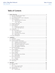
Table of Contents
page 1
Table of Contents
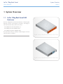
1. System Overview.......................................................................................................... 6
1.1. LaCie 12big Rack Serial SAS Enclosure............................................................................................ 6
1.2. The Enclosure Core Product............................................................................................................ 7
1.2.1. The Enclosure As Supplied.................................................................................................. 7
1.2.1.1. Product Feature Codes......................................................................................... 7
1.2.2. Drive Carrier Modules....................................................................................................... 7
1.2.3. Cables............................................................................................................................. 8
1.2.4. StorView ® Storage Management Software.......................................................................... 8
1.3. Enclosure Components................................................................................................................... 8
1.3.1. Enclosure Chassis.............................................................................................................. 8
1.3.2. Operator’s Panel............................................................................................................... 9
1.3.3. Alarms.............................................................................................................................. 9
1.3.3.1. Visible Alarms...................................................................................................... 9
1.3.3.2. Audible Alarms.................................................................................................. 10
1.4. The Plug-in Modules.................................................................................................................... 10
1.4.1. Dual Power Supply Operation.......................................................................................... 10
1.4.2. AC Power Supply............................................................................................................. 11
1.4.3. Dual Fan Cooling Module............................................................................................... 11
1.4.4. I/O Module.................................................................................................................... 12
1.4.5. Drive Carrier Module....................................................................................................... 13
1.4.5.1. Drive Status Indicators........................................................................................ 13
1.4.5.2. Anti-tamper Locks.............................................................................................. 13
1.4.6. Dummy Carrier Modules.................................................................................................. 13
1.4.7. Blank Modules................................................................................................................ 13
2. Installation................................................................................................................. 14
2.1. Introduction................................................................................................................................. 14
2.2. Planning Your Installation............................................................................................................. 14
2.2.1. Enclosure Drive Bay Numbering Convention...................................................................... 15
2.2.2. Drive Carrier Configuration.............................................................................................. 15
2.2.3. Enclosure Expansion........................................................................................................ 15
2.3. Enclosure Installation Pre-Requisites............................................................................................... 16
2.3.1. Preparation of Site and Host Server................................................................................... 16
2.3.2. Unpacking the Enclosure System....................................................................................... 16
2.4. Installation Procedures................................................................................................................. 17
2.4.1. Special Tools and Equipment............................................................................................ 17
2.4.2. Rack Installation Pre-Requisites......................................................................................... 17
2.4.2.1. Rack Mounting Rail Kit....................................................................................... 17
2.4.3. Rack Installation Procedure.............................................................................................. 18
2.4.3.1. Parts Checklist................................................................................................... 18
2.4.3.2. Installation Procedure........................................................................................ 18
2.4.4. Chassis Installation.......................................................................................................... 19
2.4.4.1. Parts Check List................................................................................................. 19
2.4.4.2. Procedure......................................................................................................... 19
2.5. Module Installation...................................................................................................................... 20
2.5.1. Drive Slot Arrangement.................................................................................................... 20
2.5.1.1. Drive Spindle Start............................................................................................. 21
2.5.2. Engaging the Drive Carrier Anti-tamper Locks.................................................................... 21
2.5.2.1. Activating the Locks........................................................................................... 21
2.6. Power Cord Connection............................................................................................................... 22
LaCie 12big Rack Serial
User Manual
Table of Contents
page 2
2.7. Enclosure Configurations.............................................................................................................. 23
2.8. Grounding Checks....................................................................................................................... 24
2.9. Data Security............................................................................................................................... 25
3. Operation.................................................................................................................. 26
3.1.
3.2.
3.3.
3.4.
3.5.
3.6.
Before You Begin......................................................................................................................... 26
Power On................................................................................................................................... 26
Audible Alarm............................................................................................................................. 27
Starting the Drives........................................................................................................................ 27
Power Down................................................................................................................................ 27
Status Indicators (LEDs)................................................................................................................. 27
3.6.1. Power Supply Unit LEDs................................................................................................... 27
3.6.2. Dual Fan Cooling Module LED......................................................................................... 28
3.6.3. Ops Panel LEDs.............................................................................................................. 28
3.6.4. I/O Module LEDs............................................................................................................ 30
3.6.5. Drive Carrier Module LEDs............................................................................................... 31
3.7. SCSI Enclosure Services (SES)........................................................................................................ 32
4. Troubleshooting & Problem Solving........................................................................... 33
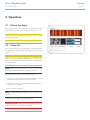
4.1. Overview.................................................................................................................................... 33
4.1.1. Troubleshooting with Storview........................................................................................... 33
4.1.2. Initial Start-up Problems................................................................................................... 33
4.1.2.1. Faulty Connections............................................................................................ 33
4.1.2.2. Alarm Sounds On Power Up............................................................................... 33
4.1.2.3. Computer Doesn’t Recognize the LaCie 12big Rack Serial.................................... 33
4.1.3. Faulty Modules................................................................................................................ 33
4.2. Audible Alarm............................................................................................................................. 33
4.2.1. Audible Alarm Mute......................................................................................................... 34
4.2.1.1. LED Test Mode.................................................................................................. 34
4.3. Troubleshooting........................................................................................................................... 35
4.3.1. System Faults.................................................................................................................. 35
4.3.2. Power Supply Faults......................................................................................................... 35
4.3.3. Dual Fan Cooling Module Faults...................................................................................... 36
4.3.4. Thermal Control.............................................................................................................. 36
4.3.5. Thermal Alarm................................................................................................................ 37
4.3.6. Thermal Faults................................................................................................................ 37
4.4. Dealing with Hardware Faults....................................................................................................... 38
4.5. Continuous Operation During Replacement................................................................................... 38
4.6. I/O Module Firmware Upgrade..................................................................................................... 38
4.6.1. I/O Module Firmware Upgrade Out of Band..................................................................... 38
4.6.2. I/O Module Firmware Upgrade In Band............................................................................ 38
4.7. Drive Firmware Upgrade.............................................................................................................. 38
5. Module Removal & Replacement................................................................................ 39
5.1.
5.2.
5.3.
5.4.
Overview.................................................................................................................................... 39
ESD Precautions.......................................................................................................................... 39
Replacing a Module..................................................................................................................... 39
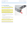
Power Supply Units...................................................................................................................... 40
5.4.1. Removing a Power Supply Unit......................................................................................... 40
5.4.2. Installing a Power Supply Unit........................................................................................... 41
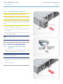
5.5. Dual Fan Cooling Module............................................................................................................ 41
5.5.1. Removing a Dual Fan Cooling Module............................................................................. 41
5.5.2. Installing a Dual Fan Cooling Module............................................................................... 42
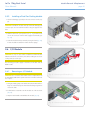
5.6. I/O Module................................................................................................................................. 42
5.6.1. Removing an I/O Module................................................................................................ 42
LaCie 12big Rack Serial
User Manual
Table of Contents
page 3
5.6.2. Installing an I/O Module.................................................................................................. 43
5.7. Drive Carrier Module................................................................................................................... 44
5.7.1. Removing a Drive Carrier Module..................................................................................... 44
5.7.2. Installing a Drive Carrier Module...................................................................................... 44
5.7.2.1. Drive Carrier Configuration................................................................................ 44
5.7.3. Installation Procedure...................................................................................................... 45
5.7.4. Dummy Carrier Module Removal/Replacement.................................................................. 46
5.8. Replacement Parts and Ancillary Items........................................................................................... 46
6. Technical Specifications.............................................................................................. 47
6.1.
6.2.
6.3.
6.4.
6.5.
6.6.
6.7.
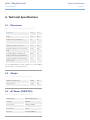
Dimensions................................................................................................................................. 47
Weight........................................................................................................................................ 47
AC Power (350W PSU)................................................................................................................. 47
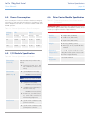
Power Consumption..................................................................................................................... 48
I/O Module Specification............................................................................................................. 48
Drive Carrier Module Specification................................................................................................ 48
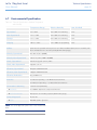
Environmental Specification.......................................................................................................... 49
7. Standards & Regulations............................................................................................ 50
7.1.
7.2.
7.3.
7.4.
7.5.
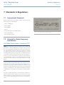
International Standards................................................................................................................ 50
Potential for Radio Frequency Interference...................................................................................... 50
European Regulations.................................................................................................................. 51
PSU Safety and EMC Compliance................................................................................................. 51
AC Power Cords.......................................................................................................................... 51
7.5.1. United States................................................................................................................... 51
7.5.2. Europe & Others............................................................................................................. 51
7.6. EMC Precautions......................................................................................................................... 51
7.7. ESD Precautions.......................................................................................................................... 51
7.8. Recycling of Waste Electrical and Electronic Equipment (WEEE)........................................................ 51
8. Contacting Customer Support.................................................................................... 52
8.1. LaCie Technical Support Contacts................................................................................................. 52
9. Warranty Information................................................................................................ 53
LaCie 12big Rack Serial
User Manual
Notices
The information in this document is subject to change without notice.
While every effort has been made to ensure that all information in this document
is accurate, the Authors accept no liability
for any errors that may arise.
No part of this document may be transmitted or copied in any form, or by any
means, for any purpose, without the written permission of the Authors.
Issue 2.0 March 18, 2008 Part No.
89515-02A
Acknowledgments
All names, brands, products or services
are trademarks or registered trademarks
of their respective companies.
What is in this guide
This user guide gives you step-by-step instructions on how to install, configure and
connect the LaCie 12big Rack Serial RAID
and LaCie 12big Rack Serial expansion
storage solution to your host computer
system, and how to use and maintain the
system.
Who should use this guide
This user guide assumes that you have a
working knowledge of the Fibre Channel
Arbitrated Loop (FC-AL) and SAS or SATA
environments into which you are installing
the LaCie 12big Rack Serial RAID and LaCie 12big Rack Serial expansion storage
solutions. If you do not have these skills,
or are not confident with the instructions in
this guide, request assistance to proceed
with the installation.
Foreword
page 4
LaCie 12big Rack Serial
User Manual
Foreword
page 5
Safety Guidelines
Safety
✦✦ Disconnect all supply power for
complete isolation.
fill the rack from the bottom up and
empty from the top down.
All plug-in modules are part of the fire enclosure and must only be removed when
a replacement can be immediately added.
The system must not be run without all
modules in place.
✦✦ The power connection must always
be disconnected prior to removal of
the Power Supply module from the
enclosure.
✦✦ System must be operated with low
pressure rear exhaust installation
(back pressure created by rack
doors and obstacles not to exceed
5 pascals (0.5 mm water gauge)).
✦✦ A safe electrical earth connection
must be provided to the power
cords. Check the grounding of the
enclosure before applying power.
✦✦ The rack design should take into
consideration the maximum operating ambient temperature for the
unit, which is 40°C (104°F) when
two power supply modules are fitted.
Permanently unplug the unit if you think
that it has become damaged in any way
and before you move it
✦✦ A LaCie 12big Rack Serial can
weigh up to 32kg (70.4lb). Do not
try to lift it by yourself.
✦✦ Do not lift A LaCie 12big Rack Serial by the handles on the plug-in
modules or those on the front of the
enclosure, they are not designed to
support the weight of the enclosure.
✦✦ In order to comply with applicable
safety, emission and thermal requirements no covers should be removed and all bays must be fitted
with plug-in modules.
✦✦ Provide a suitable power source
with electrical overload protection
to meet the requirements laid down
in the technical specification.
CAUTION: Do not remove covers from
the Power Supply module. Danger of electric shock inside. Return the Power Supply
module to your supplier for repair.
CAUTION: If this equipment is used in a
manner not specified by the manufacturer,
the protection provided by the equipment
may be impaired.
Power Supply Safety
LaCie 12big Rack Serials must only be operated from an AC power supply input voltage
range of: 100 to 120VAC or 200 to 240VAC.
AC PSU Safety Precautions
✦✦ The power cord/cable on the power
supply is used as the main disconnect device. Ensure that the socket
outlets are located near the equipment and are easily accessible.
✦✦ The equipment is designed to be operated with two working Power Supply
modules.
✦✦ To prevent overheating do not operate the enclosure with one power
supply removed for more than 30
minutes.
Rack System Precautions
The following safety requirements must be
considered when the enclosure is mounted in a rack.
✦✦ The rack design should incorporate
stabilizing features suitable to prevent the rack from tipping or being
pushed over during installation or in
normal use.
✦✦ Do not slide more than one enclosure out of the rack at one time to
avoid the danger of the rack toppling over.
✦✦ Always remove all modules and
drives to minimize weight before
loading chassis into a rack.
✦✦ When loading a rack with the units,
✦✦ The rack should have a safe electrical distribution system. It must
provide overcurrent protection
for the enclosure and must not be
overloaded by the total number
of enclosures installed in the rack.
Consideration of the chassis nameplate rating should be used when
addressing these concerns.
✦✦ The electrical distribution system
must provide a reliable earth for
each unit and the rack.
✦✦ Each power supply in each enclosure has an ground (earth) leakage
current of <1.5 mA maximum at 60
Hz, 264V per power supply. The design of the electrical distribution system must take into consideration the
total ground (earth) leakage current
from all the power supplies in all the
enclosures. The rack will require labelling with “HIGH LEAKAGE CURRENT. Ground (earth) connection
essential before connecting supply.”
✦✦ The rack when configured with the
enclosures must meet the safety requirements of UL 60950-1 and IEC
60950-1/EN 60950-1.
LaCie 12big Rack Serial
User Manual
System Overview
page 6
1.System Overview
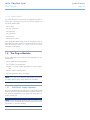
1.1. LaCie 12big Rack Serial SAS
Enclosure
The LaCie 12big Rack Serial Enclosure Platform is a 2U (rack space)
disk drive enclosure, housing twelve low profile (1 inch high), 3.5
inch form factor disc drives, which can be either:
✦✦ 3.0Gb/s direct dock SAS disk drives, or
✦✦ 3.0Gb/s direct dock SATA disk drives
✦✦ 3.0Gb/s Active/Active SATA disk drives
The system will provide up to 12Tbytes of data storage per enclosure
when 1Tb drives are installed.
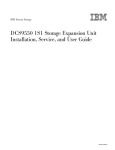
Fig. 01 - LaCie 12big Rack Serial Enclosure (Front View)
Fig. 02 - LaCie 12big Rack Serial Enclosure (Rear View)
LaCie 12big Rack Serial
User Manual
System Overview
page 7
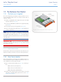
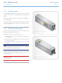
1.2. The Enclosure Core Product
1.2.1. The Enclosure As Supplied
The LaCie 12big Rack Serial design concept is based on an enclosure subsystem together with a set of plug-in modules and, as
supplied, comprises:
✦✦ Chassis and Backplane with integral (front panel mounted)
Operator’s Panel (See Fig. 06).
✦✦ Two plug-in 100-240V AC, 350W Power Supply Units (PSUs),
(see Fig. 07)
✦✦ One plug-in Dual Fan Cooling Module (see Fig. 08)
✦✦ One or two plug-in I/O modules (See Fig. 09), dependent on
customer requirement.
NOTE: If only one I/O module is installed then a Blank module
must be fitted in the unused slot. The module must be fitted in the
slot designated I/O Module 0 (shown in Fig. 05) and the Blank in
I/O Module1 (where I/O Module 0 is the lower slot and I/O Module
1 the upper slot.
IMPORTANT INFO: f only one I/O module is fitted it MUST be
installed in the Module 0 location (see Fig. 05), otherwise direct
dock SATA will not work.
1.2.1.1. Product Feature Codes
Product feature codes have been assigned to various Enclosure configurations and plug in modules as an aid to ordering information.
1.2.2. Drive Carrier Modules
Drive Carrier Modules and Dummy Carrier Modules must be ordered separately but may be included in the delivered enclosure. A
LaCie 12big Rack Serial should be fitted with:
✦✦ Up to 12 Drive Carrier Modules (See Fig. 12), containing either:
–– 3.0Gb/s direct dock SAS disk drives,
–– 3.0Gb/s direct dock SATA disk drives, or
–– 3.0Gb/s Active/Active SATA disk drives.
✦✦ Dummy Carrier Modules which must be fitted in all unused
drive bays to maintain airflow, please refer to section 1.4.6.
Dummy Carrier Modules.
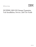
Fig. 03 - LaCie 12big Rack Serial Components
LaCie 12big Rack Serial
User Manual
System Overview
page 8
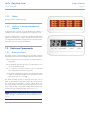
1.2.3. Cables
All cables must be ordered separately.
1.2.4. StorView ® Storage Management
Software
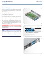
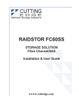
Fig. 04 - LaCie 12big Rack Serial Enclosure (Front View)
A GUI application, StorView ® Storage Management software, is
available on CD to aid the management of the 12big rack serial.
This host pc based software is a full-featured graphical HTML-based
software suite designed to configure, manage and monitor the LaCie 12big Rack Serial Module Storage Solution. For further information please refer to the Storview User Manual.
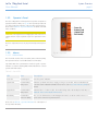
1.3. Enclosure Components
1.3.1. Enclosure Chassis
The chassis consists of a sheet metal enclosure assembly containing
a Backplane printed circuit board (PCB) and module runner system.
✦✦ The chassis front panel incorporates an integral Operator’s
(Ops) Panel.
✦✦ The Backplane PCB provides logic level signal and low voltage power distribution paths.
✦✦ Fig. 04 and Fig. 05 show front and rear views of a populated
LaCie 12big Rack Serial chassis respectively.
✦✦ The chassis is fitted with 19 inch Rack mounting features which
enable it to be fitted to standard 19 inch racks and uses 2 EIA
units of rack space (i.e. 3.5” high).
The chassis assembly contains 12 drive bays at the front, each of
which accommodates the appropriate plug-in drive carrier module.
The 12 drive bays are arranged in 3 rows of 4 drives. At the rear,
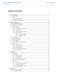
the chassis assembly contains five plug-in module bays to house two
Power Supply modules, a Dual Fan Cooling Module and two I/O
modules (which are fitted horizontally), as shown in Fig. 05.
NOTE: A drive bay is defined as the space required to house a
single 1.0” high 3.5 inch disc drive in its carrier module, shown in
Fig. 04.
Fig. 05 - LaCie 12big Rack Serial Enclosure (Rear View)
LaCie 12big Rack Serial
User Manual
System Overview
page 9
1.3.2. Operator’s Panel
The LaCie 12big Rack Serial front panel incorporates an Operator’s
(Ops) Panel with four LEDs, see Fig. 06. The Ops Panel provides the
user with a high level indication of the operation of the Enclosure.
Please refer to Table 06 - Ops Panel LED States for details of the LED
status conditions.
CAUTION: The Ops Panel is an integral part of the enclosure assembly and can only be replaced as part of a replacement enclosure.
Enclosure replacement must only be performed by trained personnel.
1.3.3. Alarms
Fig. 06 - Ops Panel
1.3.3.1. Visible Alarms
The functional modules have associated (status indicators (LEDs).
The Ops Panel shows a consolidated status for all modules.
Ops Panel LEDs show constant Green or Blue for good or positive
indication. Constant or flashing Amber LEDs indicate there is a fault
present within that module.
Table 01 - Status LEDs
LED
State
Description
Power On
Constant green
Good or positive indication
System Fault
Constant amber:
fault present
Indicates a problem with a Power Supply, Cooling or I/O module. Refer to individual modules that contain individual fault LEDs. Please refer to section 3.6. Status Indicators (LEDs) for
details.
Logical Fault
Constant amber:
fault present
Indicates failure of a drive module. The module failing will be indicated by the Fault LED, see
Table 08 - Drive Carrier Module LED Functions.
Box Identity
Constant blue:
enclosure identity
The user can illuminate this via the Management interfaces to indicate which enclosure requires service actions to be performed on it.
Please refer to Table 06 - Ops Panel LED States for a description of
the Ops Panel LED states.
LaCie 12big Rack Serial
User Manual
1.3.3.2. Audible Alarms
The LaCie 12big Rack Serial includes an Audible Alarm which indicates when a fault state is present. The following conditions will
activate the Audible Alarm:
✦✦ Fan Fault
✦✦ Over temperature
✦✦ System fault
✦✦ Logical Fault
✦✦ PSU Fault
✦✦ Removal of 1 PSU
When the Audible Alarm sounds, it may be muted by pressing the
Alarm Mute push-button which is incorporated in the enclosure front
panel. Please refer to section 4.2.1. Audible Alarm Mute for more
information on this function.
1.4. The Plug-in Modules
A LaCie 12big Rack Serial requires the following modules for normal operation:
✦✦ 2 x 350W AC Power Supply Units
✦✦ 1 x Dual Fan Cooling Module
✦✦ Either 1 or 2 I/O modules, dependant on customer requirement.
✦✦ Up to 12 Drive Carrier modules.
✦✦ Dummy Carrier modules, as required.
NOTE: Do not leave bays completely empty. Dummy Carrier modules and/or Blank modules must be fitted in all unused bays.
1.4.1. Dual Power Supply Operation
The LaCie 12big Rack Serial must always be operated with two PSUs
fitted. The two Power Supply modules operate together so that if one
fails the other maintains the power supply and cooling while you
replace the faulty unit.
NOTE: Module replacement should only take a few minutes to perform but must be completed within 30 minutes from removal of the
failed module,.to prevent overheating.
System Overview
page 10
LaCie 12big Rack Serial
User Manual
System Overview
page 11
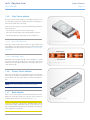
1.4.2. AC Power Supply
Two 100-240VAC 350W Power Supply Units (Fig. 07) are supplied
mounted in the rear of the enclosure as part of the enclosure core
product.
PSU voltage operating ranges are nominally 115V or 230VAC, selected automatically.
Two LEDs mounted on the rear panel of the PSU (see Fig. 07) indicate the status of the module. The LED states are defined in Table
04 - Power Supply LEDs.
1.4.3. Dual Fan Cooling Module
The Dual Fan Cooling Module (Fig. 08) provides system cooling,
thermal monitoring and control functions.
Fig. 07 - Power Supply Unit
System airflow is from front to rear of the enclosure:
✦✦ Cooling air passes over drives and through the midplane to a
central plenum.
✦✦ The Dual Fan Cooling Module pulls air from the plenum and
from the I/O modules.
✦✦ The PSUs pull cooling air from the plenum at the rear of the
enclosure.
NOTE: The system must be operated with low pressure rear exhaust
installation (back pressure created by rack doors and obstacles not
to exceed 5 pascals {0.5mm water gauge}).
An Amber FAULT LED is incorporated in the handle of the Dual Fan
Cooling Module, LED states are defined in section 3.6.2. Dual Fan
Cooling Module LED.
IMPORTANT INFO: Fan module replacement time must not exceed 10 seconds.
Fig. 08 - Dual Fan Cooling Module
LaCie 12big Rack Serial
User Manual
System Overview
page 12
1.4.4. I/O Module
The LaCie 12big Rack Serial storage expansion subsystems include
an enclosure with rear facing bays which house two SAS I/O modules, shown in Fig. 01.
The plug-in I/O modules have been designed for integration into
LaCie 12big Rack Serial storage subsystems, utilizing SAS interconnections with the host computer system.
Processors housed on the I/O modules provide enclosure management and interface to devices on the Backplane, PSU, I/O module
and Ops Panel, to monitor internal functions. These processors operate in a master slave configuration to allow failover.
The enclosure may be configured with either 1 or 2 modules. If only
1 I/O module is fitted a blank module must be fitted in the unused
bay. The module incorporates LED indicators, shown in Fig. 10 and
defined in 3.6.4. I/O Module LEDs.
Fig. 09 - I/O Module
IMPORTANT INFO: If only one I/O module is to be fitted it MUST
be installed in Module 0 location (see Fig. 05), otherwise direct dock
SATA will not function.
NOTE: The Host/Expansion Port “IN” connects the I/O Module to
a host or from the expansion out port of another enclosure. The
Expansion Port “OUT” is used to connect to the next enclosure in
an expansion configuration. The middle port is reserved for future
use. Please refer to section 2.7. Enclosure Configurations for further
information on enclosure expansion.
Fig. 10 - I/O Module Front Panel
Fig. 11 - Enclosure Rear View
LaCie 12big Rack Serial
User Manual
System Overview
page 13
1.4.5. Drive Carrier Module
The Drive Carrier module comprises a hard disk mounted in a carrier. Each drive bay will house a single Low Profile 1.0 inch high, 3.5
inch form factor disk drive in its carrier.
The front cap also supports an ergonomic handle which provides the
following functions:
✦✦ Camming of carrier into and out of drive bays.
✦✦ Positive ‘spring loading’ of the drive/backplane connector.
✦✦ An anti-tamper lock operated by a torx socket type key.
1.4.5.1. Drive Status Indicators
Fig. 12 - Drive Carrier Module
Each drive carrier incorporates two LEDs, an upper (Green) and
lower (Amber). In normal operation the green indicator will be ON
and will flicker as the drive operates. See section 3.6.5. Drive Carrier
Module LEDs
1.4.5.2. Anti-tamper Locks
Anti-tamper locks are fitted in the drive carrier handles (Fig. 13) and
are accessed through the small cutout in the latch section of the
handle.These are provided to disable the normal ‘pinch’ latch action
of the carrier handle.
Fig. 13 - Anti-tamper Lock
1.4.6. Dummy Carrier Modules
Dummy Carrier modules are provided for fitting in all unused drive
bays. They are designed as integral drive module front caps and
must be fitted to all unused drive bays to maintain a balanced airflow.
NOTE: Drives cannot be fitted in Dummy Carrier modules
1.4.7. Blank Modules
When only one I/O module is installed, a Blank module must be
fitted in the vacant I/O module slot at the rear of the enclosure to
maintain airflow and ensure correct operation (Fig. 14).
CAUTION: Operation of the Enclosure with ANY modules missing
will disrupt the airflow and the drives will not receive sufficient cooling. It is ESSENTIAL that all apertures are filled before operating the
LaCie 12big Rack Serial system.
Fig. 14 - Blank (I/O) Module
LaCie 12big Rack Serial
User Manual
Installation
page 14
2.Installation
2.1. Introduction
In this chapter, you are shown how to install your LaCie 12big Rack
Serial into an industry standard 19 inch rack cabinet and configure
the enclosure sub-system.
CAUTION: When connecting up the LaCie 12big Rack Serial, use
only the power cords supplied or cords which match the specification quoted in 7.5. AC Power Cords.
2.2. Planning Your Installation
Fig. 15 - Module Locations
Before you begin installation you should become familiar with the
configuration requirements of your LaCie 12big Rack Serial, detailed in Table 02 - Enclosure System Configuration. The correct positions of each of the optional plug-in modules are shown in Fig. 15.
Table 02 - Enclosure System Configuration
Module
Location
Drive Carrier Modules
ALL drive bays must be fitted with a populated Drive Carrier Module or Dummy Carrier Module; no
bays should be left completely empty.
Dummy Carrier Modules
Fit in all unused drive bays.
Power Supply Modules
Two PSUs must be fitted. Full power redundancy is provided while a faulty module is replaced. Install
the Power Supply modules in LH rear Bays (Fig. 15)
Dual Fan Cooling Module
Install in rear bay, as shown in Fig. 15
I/O Module
Two I/O modules (or 1 module plus1 blank module) can be fitted, according to required configuration. The modules are Installed horizontally (one above the other) in the RH rear Bay (Fig. 15).
IMPORTANT INFO: If only one I/O module is fitted it MUST be installed in the Module 0 location (see
Fig. 15), otherwise direct dock SATA will not work.
CAUTION: Blank modules or Dummy Carrier modules MUST be
fitted to ALL unused bays, there will be inadequate drive cooling if
any are left open.
LaCie 12big Rack Serial
User Manual
2.2.1. Enclosure Drive Bay Numbering
Convention
The enclosure drive bay numbering convention is shown in Fig. 15.
A drive bay is defined as the space required to house a single 1.0”
high 3.5 inch disc drive in its carrier module.
2.2.2. Drive Carrier Configuration
IMPORTANT INFO: Before you begin installation you should
become familiar with the configuration requirements of your LaCie
12big Rack Serial, see Table 02 - Enclosure System Configuration.
When planning your system configuration, please remember that
all LaCie 12big Rack Serial enclosure drive bays must be filled with
either a Drive Carrier or Dummy Carrier module, no bays should be
left completely empty.
2.2.3. Enclosure Expansion
The LaCie 12big Rack Serial has been designed as stand alone I/O
and may used as expansion with other LaCie 12big Rack Serial or
as expansion to the LaCie 12big rack Network. Please refer to section 2.7. Enclosure Configurations for details of enclosure expansion
configurations.
Installation
page 15
LaCie 12big Rack Serial
User Manual
Installation
page 16
2.3. Enclosure Installation PreRequisites
CAUTION: A LaCie 12big Rack Serial with all component parts
installed is too heavy for a single person to safely install alone into
a Rack cabinet. The following procedures describe the installation
of a LaCie 12big Rack Serial and highlights any critical co-requisite
requirements and good handling practices which we encourage you
to follow so as to ensure that a successful installation is achieved in
the easiest manner.
CAUTION: Ensure that you have fitted and checked a suitable antistatic wrist or ankle strap and observe all conventional ESD precautions when handling modules and components. Avoid contact with
Backplane components and module connectors, etc.
2.3.1. Preparation of Site and Host Server
Before you begin, make sure that the site where you intend to set
up and use your LaCie 12big Rack Serial storage system has the
following:
✦✦ Standard AC power from an independent source or a rack
Power Distribution Unit with a UPS (Universal Power Supply).
✦✦ A host computer with the correct firmware, BIOS and drivers.
Please contact your supplier for the correct software levels.
2.3.2. Unpacking the Enclosure System
The package contents and unpacking procedure are outlined in Fig.
16. The Accessory Box contains the power cords and other ordered
accessories.
NOTE: The following accessories are optional and must be ordered
separately:
✦✦ All Cables
✦✦ Rail Kits
✦✦ Software and documentation CD
Before setting up your enclosure please ensure you have the following;
✦✦ SAS HBA or motherboard with SAS HBA capability (refer to
your supplier for the latest supported list).
✦✦ Mini-SAS to Host Cable
✦✦ Power Cord
✦✦ Rack Kit (if installing within a rack)
Please refer to your supplier for a list of qualified accessories for use
with the enclosure.
Fig. 16 - Unpacking the Enclosure System
LaCie 12big Rack Serial
User Manual
Installation
page 17
2.4. Installation Procedures
2.4.1. Special Tools and Equipment
There are no special tools required but in order to complete the assembly of some configurations you may need the following:
✦✦ Torx Driver, T10 tamper resistant, black (one of these should
be included with your LaCie 12big Rack Serial for use with the
drive locks).
✦✦ Standard screwdrivers and wrenches.
2.4.2. Rack Installation Pre-Requisites
The LaCie 12big Rack Serial is designed for installation into an industry standard 19 inch cabinet capable of holding the unit.
✦✦ Minimum depth 700 mm from front flange to rear metalwork
(excludes rear cabling).
✦✦ Weight: up to 32kg dependent upon configuration per enclosure.
✦✦ A minimum gap of 25mm (1inch) clearance between the rack
cover and front of drawer; and 50mm (2 inches) rear clearance between rear of drawer and rear of rack is recommended
in order to maintain the correct air flow around the enclosure.
✦✦ The rack should present a maximum back pressure of 5 pascals (0.5mm water gauge).
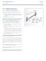
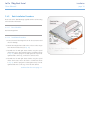
2.4.2.1. Rack Mounting Rail Kit
A set of mounting rails is available for use in 19 inch rack cabinets (Fig. 17). These rails have been designed and tested to handle
the maximum enclosure weight and to ensure that multiple LaCie
12big Rack Serial may be installed without loss of space within the
rack. Use of other mounting hardware may cause some loss of rack
space.
The rack mounting rail kit also incorporates a rear hold down mechanism to ensure shock and vibration immunity.
Please contact your supplier to ensure suitable mount rails are available for the rack you are using.
Fig. 17 - Rack Mounting Rail Kit
LaCie 12big Rack Serial
User Manual
Installation
page 18
2.4.3. Rack Installation Procedure
Please refer to the detail drawings supplied with the rack mounting
rail kit for further information
2.4.3.1. Parts Checklist
Rack Mounting Rail Kit
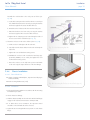
2.4.3.2. Installation Procedure
1. Remove the Rack Mounting Kit from the Accessories Box and
check for damage.
2. Attach left and right chassis slides to the enclosure sides using 8
M3 x 4 button head screws (see Fig. 18).
3. Assemble the left and right chassis latches using the special
chassis latch screws. Ensure that the latch is orientated as shown
in Fig. 18, with the spring arm located against its stop.On the
right hand this is at the top, on the left it is at the bottom.
4. Assemble the left and right chassis latches using the special
chassis latch screws. Ensure the latch is orientated as shown
in Fig. 18, with the spring arm located against its stop. On the
right hand side this is at the top, on the left at the bottom.
continued on the next page >>
Fig. 18 - Securing Chassis Slides to Enclosure
(steps 1 & 2)
LaCie 12big Rack Serial
User Manual
Installation
page 19
Assemble the rack brackets to the rack posts as follows (see
Fig. 20).
a. Locate the location pin at the rear of the rail into a rear rail post
hole. Attach the bracket to the rear rack post using the washers
and screws supplied. The screws should be left loose.
b. Extend the rail to fit between the front and rear rack posts.
c. Attach the bracket to the front rack post using the washers
and screws supplied. The screws should be left loose.
d. Tighten the two clamping screws located along the inside of
the rear section of the rack bracket (see Fig. 19).
5. Mount the enclosure in the rack as follows (refer to Fig. 20):
a. Lift the enclosure and align it with the rack rails.
b. Carefully insert the chassis slides into the rack rails and push
fully home.
Fig. 19 - Rack Mounting Rail Kit
c. Tighten the rear rack bracket mounting screws.
d. Withdraw the enclosure until it reaches the hard stops (approximately 400mm, 16.75 inches) and tighten the front
rack bracket mounting screws.
e. Return the enclosure to the fully home position and attach
to the rack using the captive fasteners on the front flanges.
2.4.4. Chassis Installation
2.4.4.1. Parts Check List
✦✦ Chassis (complete with Backplane, Ops Panel and all plug-in
modules installed).
✦✦ Rack mounting thumbscrews (4 off).
Fig. 20 - Mounting the Enclosure into a Rack (step 4)
2.4.4.2. Procedure
1. Fit the Rack Mounting Rail Kit in accordance with the mounting
kit Installation procedure.
2. Check chassis for damage.
3. Slide the chassis assembly onto the rack rails until the front flanges
engage on the rack. Ensure the chassis is centrally located.
4. If in doubt about correct orientation, the Operator’s Panel
should be on the left hand side of the enclosure.
5. Tighten the two mounting thumbscrews present on each chassis
flange.
LaCie 12big Rack Serial
User Manual
Installation
page 20
2.5. Module Installation
The LaCie 12big Rack Serial is supplied fully populated with all
plug-in modules installed, see Table 02 - Enclosure System Configuration for system configuration information.
✦✦ A Single Controller system, LaCie 12big Rack Serial, will be
fitted with 1 x I/O Module in Module 0 location, see Fig. 28
and 1 x LRC Blank Assembly. (A LaCie 12big Rack Serial system can be upgraded to a LaCie 12big Rack Serial system at
a future date.)
✦✦ A Dual Controller system, LaCie 12big Rack Serial, will be
fitted with 2 x I/O Modules.
For information on removal/replacement of plug-in modules, please
refer to Chapter 5. Module Removal & Replacement.
NOTE: Replaceable parts and product feature codes are listed in
section 5.8. Replacement Parts and Ancillary Items.
2.5.1. Drive Slot Arrangement
Each enclosure has 12 drives which are referenced by their location as shown in Table 03 - Drive Slot Arrangement: Enclosure Front
View. Drives are numbered column/row.
Table 03 - Drive Slot Arrangement: Enclosure Front View
Column/
Row
1/#
2/#
3/#
4/#
#/1
Drive 1
Drive 2
Drive 3
Drive 4
#/2
Drive 5
Drive 6
Drive 7
Drive 8
#/3
Drive 9
Drive 10
Drive 11
Drive 12
The LaCie 12big Rack Serial system supports SAS and SATA drives.
However, mixing of drive types within a single enclosure is not supported. The enclosure has no restrictions on drive location.
LaCie 12big Rack Serial
User Manual
Installation
page 21
2.5.1.1. Drive Spindle Start
Drive spindle start is automatically controlled via the I/O modules
controlling the power control circuit of the Backplane. With two active PSUs present all drives will start immediately. If only a single
PSU is present then the system will start in two groups of 6 drives,
separated by a 12 second delay.
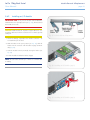
Fig. 21 - Activating the Anti-tamper Lock
2.5.2. Engaging the Drive Carrier Antitamper Locks
The anti-tamper locks are fitted in the drive carrier handles and are
accessed through the small cutout in the latch section of the handle.
Drives are supplied with the locks set in the locked position.
2.5.2.1. Activating the Locks
1. Rotate the torx driver provided in a clockwise direction until the
indicator is visible in the aperture beside the key.
2. Remove the key.
De-activation is the reverse of this procedure, that is: rotate the
torx driver in an anti-clockwise direction until the indicator is no
longer visible in the aperture beside the key.
NOTE: A drive carrier cannot be installed if its anti-tamper lock is
activated outside the Enclosure.
LaCie 12big Rack Serial
User Manual
Installation
page 22
2.6. Power Cord Connection
Parts checklist: Power cord to requisite local standards
CAUTION: Rack Installation: The enclosures should be installed
SECURELY in the rack before connecting to the power supply. Danger of the enclosure moving and possibly slipping out of the rack
unless secured.
1. Attach the power cord to the Power Supply modules,
2. Attach the power cord to the Power Distribution Unit (Fig. 23) in
the rack or other power source.
CAUTION: Before applying power, carry out the grounding checks
detailed in section 2.8. Grounding Checks.
CAUTION: The power connections must always be disconnected
prior to removal of the Power Supply module from the enclosure.
See section 5.4.1. Removing a Power Supply Unit.
Fig. 22 - Cable Strain Relief Bales
Fig. 23 - Power Cord Connections
LaCie 12big Rack Serial
User Manual
Installation
page 23
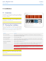
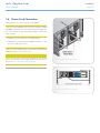
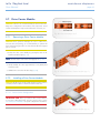
2.7. Enclosure Configurations
The basic configuration is a single LaCie 12big Rack Serial connected to a single Host Bus Adaptor (HBA), see Fig. 24.
Before setting up your enclosure please ensure that you have the
following:
✦✦ SAS HBA
✦✦ Mini-SAS to Host Cable
✦✦ Power Cable
✦✦ Rack kit (if installing within a rack)
Fig. 24 - Basic Configuration
Please refer to your supplier for a list of qualified accessories for use
with LaCIe 12big rack serial enclosures.
Multiple LaCie 12big Rack Serials may be connected together using
SAS patch cables, up to a maximum of 8 enclosures. There are three
main expansion configurations
✦✦ Single Host, Single Connection, shown in Fig. 25
–– Single I/O module
–– Supports SAS or SATA drives
–– Expansion up to 96 drives.
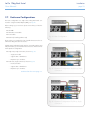
✦✦ Dual Host, Single Connection, shown in Fig. 26
–– Dual I/O module
–– Supports SAS or SATA drives
–– Expansion up to 96 drives.
continued on the next page >>
Fig. 25 - Expansion Configuration: Single Host, Single
Connection
Fig. 26 - Expansion Configuration: Dual Host, Single
Connection
LaCie 12big Rack Serial
User Manual
Installation
page 24
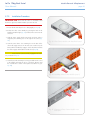
✦✦ Dual Host, Dual Connection, shown in Fig. 27
–– Dual I/O module
–– Supports SAS or SATA drives
–– Expansion up to 96 drives
NOTE: Direct dock SATA drives will not work with multiple host
connections.
NOTE: The middle port on the module is for future use.
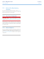
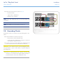
2.8. Grounding Checks
Perform these checks to ensure that a safe grounding system is provided.
✦✦ If a Rack Distribution System is being used.
–– Ensure power is removed from the rack.
–– Connect the LaCie 12big Rack Serial power cord to the
rack distribution and the enclosure.
✦✦ If a direct connection is made with the LaCie 12big Rack Serial
power cord, ensure that it is connected to the enclosure.
CAUTION: Some electrical circuits could be damaged if external signal cables or power control cables are present during the
grounding checks.
✦✦ Check for continuity between the earth pin of the IEC 320
connector on one of the Power Supply modules and any exposed metal surface of the LaCie 12big Rack Serial.
Fig. 27 - Expansion Configuration: Dual Host, Dual
Connection
LaCie 12big Rack Serial
User Manual
2.9. Data Security
✦✦ Power down your host computer and all attached peripheral
devices before beginning installation.
✦✦ Each enclosure contains up to 12 removable disk drive modules. Disk units are fragile. Handle them with care, and keep
them away from strong magnetic fields.
✦✦ All the supplied plug-in modules, dummy carriers and blank
modules must be in place for the air to flow correctly around
the enclosure and also to complete the internal circuitry.
✦✦ If the subsystem is used with plug-in modules, dummy carriers
or blank modules missing for more than a few minutes, the
enclosure can overheat, causing power failure and data loss.
Such use may also invalidate the warranty.
✦✦ If you remove any drive module, you may lose data.
–– If you remove a drive module, replace it immediately. If
the drive module is faulty, replace it with one of the same
type and capacity
✦✦ Ensure that all disk drives are removed from the enclosure
before attempting to manhandle or move the rack installation.
✦✦ Do not abandon your backup routines. No system is completely infallible.
Installation
page 25
LaCie 12big Rack Serial
User Manual
Operation
page 26
3.Operation
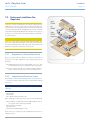
3.1. Before You Begin
Before powering up the LaCie 12big Rack Serial please ensure that
all the modules are firmly seated in their correct bays, see Fig. 28.
CAUTION: The LaCie 12big Rack Serial must only be operated
with two PSUs installed.
3.2. Power On
Power on the enclosure by connecting cables to the Power Distribution Unit (PDU), or powering on the PDU, then power on the Host
system.
CAUTION: Do not operate this equipment until the ambient temperature is within the specified operating range. If the drives have
been recently installed ensure they have had time to acclimatize before operating them.
NOTE: Please refer to section Table 06 - Ops Panel LED States for
details of the Ops Panel LEDs and related fault conditions.
Follow the procedure below to Power On the enclosure.
1. Apply power to the enclosure. Press the PSU switches to the ON
position. Both PSUs should be powered on together.
2. All LEDs on the OPS Panel should be illuminated when the enclosure power is activated.
3. Power on the Host system(s).
NOTE: ‘he alarm will beep momentarily at power on, this is normal
operation.
4. Wait one minute before accessing the system(s).
IMPORTANT INFO: If power is lost for any reason, on restoration
of power the enclosure will re-start automatically.
Fig. 28 - Module Locations
LaCie 12big Rack Serial
User Manual
3.3. Audible Alarm
Operation
page 27
Table 04 - Power Supply LEDs
The enclosure subsystem includes an Audible Alarm which indicates
when a fault state is present. Please refer to section 4.2. Audible
Alarm for further information.
Power On &
OK(Green)
Module Fault
(Amber)
Status
OFF
OFF
No AC power (either
PSU)
3.4. Starting the Drives
OFF
ON
✦✦ No AC power (this
PSU only), OR
Unless otherwise selected during installation, with two active PSUs
fitted, all drives in the enclosure should immediately start their motors. If this has not occurred one of the following conditions may
exist:
✦✦ PSU Fault (over
temp, over voltage,
over current, PSU
fan fail)
✦✦ There may be a power problem (an alarm and power fault
indication would normally be active).
ON
OFF
AC present, PSU on and
OK
✦✦ If there is only one PSU present, the drive motors will spin up
in a delayed sequence, i.e. two groups of 6 drives, separated
by a 12 second delay.
ON
ON
Fan Fault
3.5. Power Down
✦✦ To power the Enclosure down, remove power at the power
source.
✦✦ Press the PSU switches to the OFF position.
3.6. Status Indicators (LEDs)
Amber fault LEDs can indicate the following fault conditions:
✦✦ Lit Solid: critical fault
✦✦ Flashing: non-critical fault
3.6.1. Power Supply Unit LEDs
The PSU incorporates 2 LEDs.
✦✦ Under Normal conditions the Power On LED should be illuminated constant GREEN
✦✦ If a problem is detected the Module Fault LED will be illuminated constant AMBER.
The Power Supply module LED states are detailed in Table 04 Power Supply LEDs.
LaCie 12big Rack Serial
User Manual
Operation
page 28
3.6.2. Dual Fan Cooling Module LED
An Amber FAULT LED is incorporated in the handle of the Dual Fan
Cooling Module, defined in Table 05 - Dual Fan Cooling Module
LED.
Table 05 - Dual Fan Cooling Module LED
Status
Module Fault (Amber)
Enclosure Off - qualified by
PSU and I/O module OK
LEDs
OFF
Enclosure On - Fan OK
OFF
Both Fans Fail
ON
Single Fan Fail
Flashing
Fig. 29 - Ops Panel
3.6.3. Ops Panel LEDs
The Ops Panel displays the aggregated status of all the modules.
The Ops Panel LEDs are shown in Fig. 29 and defined in Table 06
- Ops Panel LED States.
NOTE: The Ops Panel is supplied as an integral part of the enclosure core product and is not user replaceable.
Table 06 - Ops Panel LED States
Ops Panel LEDs
Power On
Green/
Amber
System
Fault
Amber
Logical
Fault*
Amber
Box
Identify
Blue
ON
ON
ON
ON
ON
OFF
any
any
ON
ON
any
any
Other Associated
LEDs or Alarms
State Description
LaCie 12big Rack Serial Activity LEDs flash
Dual Fan Cooling
Module Fault LED On
Ops Panel power on (5s) test state
S0
Power On, all functions good
S4
Dual Fan Failure
S1
Single Fan Failure
Continuous beep
ON
Flashing
any
any
Dual Fan Cooling
Module Fault LED
On
Intermittent beep
continued on the next page >>
LaCie 12big Rack Serial
User Manual
Operation
page 29
Ops Panel LEDs
ON
Flashing
any
any
Other Associated
LEDs or Alarms
State Description
PSU Module Fault
LED On
S1
Single PSU Failure
Intermittent beep
ON
Flashing
any
any
Intermittent beep
S1
PSU Removed
ON
Flashing
any
any
Intermittent beep
S1
Over or under Temperature Warning
ON
ON
any
any
Continuous beep
S4
Over or under Temperature Critical
ON
ON
any
any
Continuous beep
S4
Voltage Critical
ON
OFF
As per Drive
Fault LED
any
None
Drive Critical
ON
OFF
As per
Drive
Fault LED
any
None
Drive Non-critical
ON
On
any
any
LaCie 12big Rack Serial
Fault & ID LEDs On
S4
I/O module watchdog failure
S1
I/O module soft (or POST) failure
S1
Other I/O module fault
Continuous beep
ON
Flashing
any
any**
LaCie 12big Rack Serial
Fault & ID LEDs On
Intermittent beep
ON
Flashing
any
any**
LaCie 12big Rack Serial
Fault & ID LEDs On
Intermittent beep
LED Operation set via SES Control page 0x02
ON
any
OFF
any
Power On, all functions good
ON
any
As per
Drive
Fault LED
any
Drive bay Fault LED
Flash
POST Fault bit set for any Array Device Element.
ON
any
As per
Drive
Fault LED
any
Drive bay Fault LED
Flash
Other Array bits set for any Array Device Element.
ON
ON
any
any
Continuous beep
ON
any
any
any
Intermittent beep
INFO, NON-CRIT, CRIT bits set in Audible Alarm
element
ON
any
any
any
Continuous beep
UNRECOV bit set in Audible Alarm element
continued on the next page >>
S4
UNRECOV bit set in Audible Alarm element
LaCie 12big Rack Serial
User Manual
Operation
page 30
LED Operation set via SES Control page 0x02
ON
Flashing
any
any
REQUEST WARNING bit set in Enclosure element
ON
ON
any
any
REQUEST FAILURE bit set in Enclosure element
ON
any
any
Flashing
RQST IDENT bit set in Enclosure element.
* If a LaCie 12big Rack Serial fault LED is fitted, this will be set for
all the above conditions. In addition this LEd will flash for an I/O
module soft failure.
** Logical Fault LED will take the state of the highest priority drive bay
fault LED. Please refer to notes in Table 08 - Drive Carrier Module LED
Functions for Drive Slot LED states.
NOTE: See Table 09 - Alarm States for descriptions of the audible
alarms.
NOTE: The I/O Alarm pattern is a 1 second ON, 1 second OFF
sequence applied to all 12 Activity LEDs.
3.6.4. I/O Module LEDs
Each I/O module incorporates two (GREEN) indicators.
Table 07 - I/O Module LEDs
LED Functions
Status
Activity LEDs (Green)
ON
Ready, No Traffic
Flashing
Active
Flashing (All, 1Hz)
Fault Condition or Rebooting
OFF
Not Ready, No Power
Fault LED (Amber)
ON
Module Fault (see Table 06 Ops Panel LED States)
OFF
Module OK
ID LED (Green)
continued on the next page >>
LaCie 12big Rack Serial
User Manual
Operation
page 31
LED Functions
Status
ON
Identifies specific module
when module fault occurs.
(see Table 06 - Ops Panel
LED States)
OFF
Module OK
All Activity LEDs flash synchronously (1Hz) when there is a Fault condition.
3.6.5. Drive Carrier Module LEDs
Disk drive status is monitored by a Green LED and an Amber LED
mounted on the front of each Drive Carrier module, providing the
following indications:
Table 08 - Drive Carrier Module LED Functions
State
SES Indications
Green
Amber
No drive fitted
Off
Off
Drive Installed and operational
On/Blink off with
activity
Off
Drive Ident
RQST IDENT bit set in Array Device Element
any
Flash Rate 1
Drive Fault
RQST FAULT bit set in Array Device Element
any
On
Array Fault
RQST CONS CHECK. RQSTIN CRIT ARRY, RQSTREBUILD/REMAP, RQST R/R ABORT bits set in Array
Device Element
any
Flash Rate 2
Drive Critical
Power applied but phy fails to detect presence of an End
Device
any
On
Drive Non-Critical
Drive negotiated a 1.5Gbps link
any
any
NOTE: 1 Flash Rate 1 = 1 second ON, 1 second OFF.
NOTE: 2 Flash Rate 2 = 2 seconds ON, 2 seconds OFF.
NOTE: Fault LED Priorities: If multiple conditions in Table 08 - Drive
Carrier Module LED Functions are met, the fault LED will adopt the
setting with the lowest priority value (i.e. a priority 1 outranks apriority 2 condition).
LaCie 12big Rack Serial
User Manual
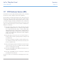
3.7. SCSI Enclosure Services (SES)
SCSI Enclosure Services (SES) forms the primary route to accessing
the Enclosure’s status, diagnostic and control capabilities.
This information is transferred in-band over the SAS topology. The
Enclosure presents a SCSI Target on the topology to which a subset
of SCSI SPC commands can be directed. SES consists of a series
of numbered ‘pages’ with static and dynamic status coming from
the enclosure and control information written to the enclosure. SES
pages are transferred through use of the SCSI SPC Send and Receive
diagnostics commands.
✦✦ SES Status Pages 0 and 1 are read to determine the page
information available and how to interpret it. Page 0 has a
list of supported SES pages. Page 1 contains ‘inquiry’ type
data (product strings etc.) and a list of the number and type of
standard elements that are supported (e.g. disk drive/ power
supply / SAS expander) This information would normally be
polled at start of day.
✦✦ SES Status Page 2 is the main source of enclosure status information which would be regularly polled, for example at 10
second intervals.
The type of information available would be disk drive presence and drive fault LED status, PSU status, fan status, temperature, expander status.
✦✦ SES Control Page 2 provides a mechanism for control of some
of the enclosures resources, for example turning the audible
alarm on or blinking drive fault leds
✦✦ SES Status page 0x0A provides additional information, for example drive SAS Addresses.
✦✦ SES Status page 0x0E provides a mechanism to download
new firmware to the enclosure.
StorView uses SES as it’s mechanism for obtaining Enclosure information.
Operation
page 32
LaCie 12big Rack Serial
User Manual
Troubleshooting & Problem Solving
page 33
4.Troubleshooting & Problem Solving
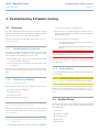
4.1. Overview
Serial to the host computer are fitted correctly.
The LaCie 12big Rack Serial includes a processor and associated
monitoring and control logic to enable them to diagnose problems
within the enclosure’s power, cooling and drive systems.
2. Check that there is a valid SAS signal present at the I/O connector by observing the state of the LEDs. A green LED indicates
that the signal is present.
If a fault is indicated on the Ops Panel, please refer to Table 06 Ops Panel LED States.
3. Check the I/O module setup as follows:
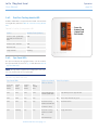
4.1.1. Troubleshooting with Storview
––
If a single I/O module is fitted, check that it has been
correctly installed in Slot 0.
–– Check that the maximum cable length has not been exceeded.
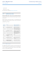
The StorView ® Storage Management software can be used to select
and determine whether a component or sub-component is faulty.
This information can be displayed in one of two ways:
IMPORTANT INFO: For details on how to remove and replace a
plug-in module please refer to 5. Module Removal & Replacement.
✦✦ The Graphical View shows a real-world representation of the
enclosures and their components:
If you have any problems in configuring your system please refer to
your HBA supplier.
✦✦ The Tree View shows a hierarchical view of the system, using
icons and text.
The quick way to get information on a component is simply to hover
the mouse over it. A large tooltip will appear giving the relevant
data.
4.1.3. Faulty Modules
4.1.2. Initial Start-up Problems
CAUTION: PSU bays must not be left empty. Please refer to section
5.4. Power Supply Units for PSU removal/replacement procedures.
4.1.2.1. Faulty Connections
First check that you have wired up the subsystem correctly. Then, if:
✦✦ cords are missing or damaged
✦✦ plugs are incorrect
It is recommended that a faulty Power Supply Module is replaced as
soon as possible.
If one fan fails in a Dual Fan Cooling Module then the complete
module must be replaced. Please refer to section 5.5. Dual Fan
Cooling Module for cooling module removal/replacement procedures.
✦✦ cords are too short
Call your supplier for a replacement.
4.1.2.2. Alarm Sounds On Power Up
Under normal conditions the alarm sounds on Power Up and clears
after one second. If the alarm does not clear, please refer to section
4.2. Audible Alarm.
4.2. Audible Alarm
The enclosure subsystem includes an Audible Alarm which indicates
when a fault state is present. The following conditions will activate
the Audible Alarm:
✦✦ Fan Fault
✦✦ Voltage out of range
✦✦ Over temperature
4.1.2.3. Computer Doesn’t Recognize the LaCie 12big
Rack Serial
1. Check that the SAS interface cables from the LaCie 12big Rack
✦✦ System fault
✦✦ Logical fault
LaCie 12big Rack Serial
User Manual
Troubleshooting & Problem Solving
page 34
✦✦ PSU Fault
✦✦ Removal of 1 PSU
The alarm states are defined in Table 09 - Alarm States.
4.2.1. Audible Alarm Mute
When the Audible Alarm sounds, it may be muted by pressing the
Alarm Mute push-button, located on the Ops panel. Automatic muting will take place after two minutes if the mute switch is not manually operated.
When the alarm is muted it will continue to sound with 20 second
beeps to indicate that a problem still exists, it will be silenced when
all problems are cleared.
Table 09 - Alarm States
Alarm
State
Action
Action with Mute
button pressed
S0
Normal Mode: Silent
Bleep twice, Flash all
LEDs for self test until
error or pressed again.
S1
Fault Mode: 1s on/1s
off
Transition to S2.If mute
not pressed, after 2
minutes, automatically
transition state S2
S2
Remind Mode: Intermittent Bleep
None
S3
Muted Mode: Silent
None: only supported
from SES
S4
Critical Fault: mode:
Continuous alarm
None: Mute not active
4.2.1.1. LED Test Mode
The Alarm Mute push-button can also be used to activate the selftest feature for the LEDs on the Ops Panel. The test is activated when
you press the Mute push-button while no faults are present. While
the test is running all LEDs will flash.
LaCie 12big Rack Serial
User Manual
Troubleshooting & Problem Solving
page 35
4.3. Troubleshooting
The following sections describe problems, with possible solutions,
which can occur with your LaCie 12big Rack Serial Enclosure.
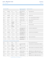
4.3.1. System Faults
Table 10 - Troubleshooting System Faults
Symptom
1. I/O Module Fault LEDs illuminated Amber & ID LEDs
illuminated GREEN when
there is a Fault condition.
Cause
Action
The ESI processor has detected an internal fault on one
of the following modules: PSU, Cooling, I/O Module
Replace faulty module as appropriate:
✦✦ PSU
✦✦ Cooling
✦✦ I/O Module
2. Audible Alarm sound
NOTE: See also section 4.3.6. Thermal Faults.
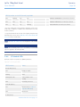
4.3.2. Power Supply Faults
Table 11 - Troubleshooting Power Supply Faults
Symptom
1. Ops Panel SYSTEM FAULT
LED AMBER
Cause
1. Any power fault.
2. A fan failure.
2. An AMBER LED on one
or more Power Supply
Modules.
3. A thermal condition which could cause PSU overheating.
3. Audible Alarm sounding.
4. Fault: on one of the following modules:
✦✦ PSU
✦✦ Cooling
✦✦ I/O Module
5. Removal of 1 PSU
Action
1. Check AC power connections to
Power Supply module are live.
2. Disconnect the Power Supply module from AC power and remove the
module from the system, Re-install: if
problem persists, replace Power Supply Module.
3. Reduce the ambient temperature.
4. Replace faulty module as appropriate:
✦✦ PSU
✦✦ Cooling
✦✦ I/O Module
LaCie 12big Rack Serial
User Manual
Troubleshooting & Problem Solving
page 36
4.3.3. Dual Fan Cooling Module Faults
Table 12 - Troubleshooting Dual Fan Cooling Module Faults
Symptom
1. Ops Panel SYSTEM FAULT
LED AMBER
2. Audible Alarm sounding.
3. AMBER LED on Dual Fan
Cooling Module ON.
Cause
1. Both Fans Failed
OR
2. Single Fan failure.
Action
Both fans fail: Replace faulty Cooling module.
Single fan fails: the complete Cooling module must be replaced.
OR
4. AMBER LED on Dual Fan
Cooling Module Flashing.
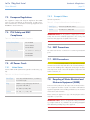
4.3.4. Thermal Control
The LaCie 12big Rack Serial uses extensive thermal monitoring and
take a number of actions to ensure component temperatures are
kept low and also to minimize acoustic noise. Air flow is from front
to rear of the enclosure.
Table 13 - Troubleshooting Thermal Control
Symptom
Cause
If the ambient air is cool (below
25 °C) and the fans are observed
to increase in speed then some
restriction on airflow may be
causing additional internal temperature rise.
The first stage in the thermal control process is for the
fans to automatically increase in speed when a thermal
threshold is reached. This may be caused by higher ambient temperatures in the local environment and may be
perfectly normal.
NOTE: This is not a fault condition.
NOTE: This threshold changes according to the number
of drives and power supplies fitted.
Action
1. Check the installation for any airflow
restrictions at either the front or rear
of the enclosure. A minimum gap of
25mm at the front and 50mm at the
rear is recommended.
2. Check for restrictions due to dust
build-up, clean as appropriate.
3. Check for excessive re-circulation of
heated air from rear to the front. Use
in a fully enclosed rack installation is
not recommended.
4. Reduce the ambient temperature.
LaCie 12big Rack Serial
User Manual
Troubleshooting & Problem Solving
page 37
4.3.5. Thermal Alarm
Table 14 - Troubleshooting Thermal Alarm
Symptom
1. Ops Panel SYSTEM FAULT
LED AMBER.
2. An AMBER LED on one or
more Power Supply module.
Cause
Action
1. If the internal temperature measured in the airflow
through the enclosure exceeds a pre-set threshold a
thermal alarm will sound.
1. Check local ambient environment
temperature is below the upper 40°C
specification.
2. Dual Fan Cooling Module failure
2. Check the installation for any airflow
restrictions at either the front or rear
of the enclosure. A minimum gap of
25mm at the front and 50mm at the
rear is recommended.
3. Audible Alarm Sounding.
4. Air temperature exiting PSU
above 55°C.
3. Check for restrictions due to dust buildup, clean as appropriate.
4. Check for excessive re-circulation of
heated air from rear to the front. Use in
a fully enclosed rack installation is not
recommended.
5. If possible shutdown the enclosure and
investigate the problem before continuing.
6. Replace Dual Fan Cooling Module
4.3.6. Thermal Faults
Table 15 - Troubleshooting Thermal Faults
Symptom
1. ALL AMBER LEDs on the Ops
Panel and drive bays illuminated flash.
2. Audible Alarm sounds almost continuously and cannot be muted.
Cause
At a higher threshold than the Thermal Alarm (this should
already have been activated).
OR - All fans have failed.
OR - Only 1 fan operating and the internal temperature
is 40° C or above.
Action
1. Switch Off immediately.
2. Check for airflow restrictions.
3. Check Power Supply module faults.
4. Check for excessive local temperatures.
LaCie 12big Rack Serial
User Manual
Troubleshooting & Problem Solving
page 38
4.4. Dealing with Hardware Faults
4.6. I/O Module Firmware Upgrade
Ensure that you have obtained a replacement module of the same
type before removing any faulty module.
LaCie periodically issues updates to the Storage Enclosure Processor
(SEP) firmware as part of a scheduled release package, this code
needs to be loaded onto each I/O in the enclosure.
CAUTION: If your LaCie 12big Rack Serial is powered up and you
remove any module, replace it immediately. If the enclosure is used
with plug-in modules, Dummy Carriers or Blank modules missing
for more than a few minutes, the Enclosure can overheat, causing
power failure and data loss. Such use will invalidate the warranty.
There are two ways to perform this upgrade, one uses the diagnostic
serial port on the LaCie 12big Rack Serial (Out of Band) and the
other uses SCSI commands over the SAS topology (In Band)
✦✦ Replace a faulty drive with a drive of the same type and equal
or greater capacity.
4.6.1. I/O Module Firmware Upgrade Out
of Band
✦✦ All drive bays must be fitted with a SAS/SATA Drive Carrier
or Dummy Carrier module in order to maintain a balanced
air flow.
This method uses a Host PC running a ‘terminal’ application to
download the firmware using an RS232 serial cable to connect to
the I/O module to be upgraded.
✦✦ All of the supplied plug-in power supply units, electronics
modules, dummy carriers and blank modules must be in place
for the air to flow correctly around the cabinet.
Instructions for this method are supplied with the upgrade package
in the LaCie 12big Rack Serial Upgrade Procedure document.
Please refer to 5. Module Removal & Replacement for details of
module removal/replacement procedures.
4.6.2. I/O Module Firmware Upgrade In
Band
4.5. Continuous Operation During
Replacement
Depending on how the LaCie 12big Rack Serial is configured, if a
disk unit fails, it can normally be replaced without interrupting the
use of the system.
In addition, each enclosure contains two PSUs, either of which can
maintain power and cooling to the subsystem while the other is replaced.
NOTE: The PSU replacement time must be as short as possible
(<30 minutes) as the enclosure is designed to operate with two PSUs
installed.
IMPORTANT INFO: in the event of a cooling fan failure the complete Dual Fan Cooling Module must be replaced within <10 seconds.
This method uses the data path to transfer the firmware update to
the LaCie 12big Rack Serial, hence no extra cables should be required. SCSI commands are issued to transfer the data blocks. There
are two methodologies, the preferred method uses SES page 0x0E
download but a Write Buffer method is also available.
4.7. Drive Firmware Upgrade
CAUTION: Upgrading firmware in SAS and SATA drives should
only be performed by the most experienced users. If firmware is incorrectly upgraded it could result in a drive becoming non-functional.
LaCie 12big Rack Serial
User Manual
5.Module Removal & Replacement
5.1. Overview
In this chapter, you are shown how to remove and replace a plug-in
module in your LaCie 12big Rack Serial enclosure.
IMPORTANT INFO: The Ops Panel is an integral part of the
enclosure assembly and can only be replaced with a replacement
enclosure. The enclosure should only be replaced by trained personnel.
5.2. ESD Precautions
CAUTION: Fit and check a suitable anti-static wrist or ankle strap
and observe all conventional ESD precautions when handling LaCie
12big Rack Serial plug-in modules and components. Avoid contact
with backplane components and module connectors, etc.
5.3. Replacing a Module
CAUTION: Whenever replacing a module NEVER leave an EMPTY
space in the rear of the enclosure, obtain a replacement before
removing the faulty part.
Please refer to chapter 2. Installation for information on the initial
installation of the plug-in modules in the LaCie 12big Rack Serial
enclosure.
CAUTION: Observe all conventional ESD precautions when handling LaCie 12big Rack Serial modules and components. Avoid
contact with Backplane components and module connectors, etc.
Module Removal & Replacement
page 39
LaCie 12big Rack Serial
User Manual
Module Removal & Replacement
page 40
5.4. Power Supply Units
5.4.1. Removing a Power Supply Unit
CAUTION: Do not remove the faulty PSU unless you have a replacement unit of the correct type ready for insertion. the system
must not be operated without both PSUs in place.
CAUTION: To prevent overheating do not operate the enclosure
with one PSU removed for more than 30 minutes.
As there should always be two power supply units installed, the system can continue working while replacing the faulty module.
1. Make sure you identify the faulty PSU correctly, from the two
PSUs installed. The Module Fault LED on the faulty PSU will be
illuminated Amber.
2. Remove the power cables from the AC power source.
3. Push the latch on the PSU handle to the right (Fig. 30), then grip
the handle and pull the PSU out of the enclosure. take care not
to drop and lose the cable retaining spring.
CAUTION: Do not remove covers from the PSU. Danger of electric
shock inside. Return the PSU to your supplier for repair.
Fig. 30 - Removing a Power Supply Module
LaCie 12big Rack Serial
User Manual
Module Removal & Replacement
page 41
5.4.2. Installing a Power Supply Unit
CAUTION: Do not mix PSUs of different types or makes.
1. Check for damage, especially to the rear connector on the PSU.
CAUTION: Handle the module carefully and avoid damaging the
connector pins. Do not install the module if any pins appear to be
bent.
2. Slide the module into the enclosure (Fig. 31).
3. Push the module home. A click should be heard as the handle
latch engages.
4. Connect the power supply cords to the power source and engage the retaining spring.
Fig. 31 - Inserting a Power Supply Module
NOTE: The alarm will sound until the new PSU is operating correctly.
5.5. Dual Fan Cooling Module
5.5.1. Removing a Dual Fan Cooling
Module
1. Grasp latch (Fig. 32) between thumb and forefinger. Squeeze
thumb and forefinger together to release the latch.
NOTE: The module should be orientated so that the handle is always at the bottom of the module.
Fig. 32 - Dual Fan Cooling Module Latch
2. Pull the latch outward to cam the module out of the enclosure
(Fig. 33).
3. Withdraw the module.
Fig. 33 - Removing a Dual Fan Cooling Module
LaCie 12big Rack Serial
User Manual
Module Removal & Replacement
page 42
5.5.2. Installing a Dual Fan Cooling Module
1. Check for damage, especially to the rear connector on the supply.
CAUTION: Handle the module carefully and avoid damaging the
connector pins. Do not install the module if any pins appear to be
bent.
2. With the latch in the open position (see Fig. 32), slide the module into the enclosure until the latch engages automatically (see
Fig. 34).
3. Cam the module home by manually closing the latch (Fig. 35).
A click should be heard as the module latches engage.
Fig. 34 - Dual Fan Cooling Module Installation
5.6. I/O Module
CAUTION: If only one I/O module is fitted then a Blank module
MUST be fitted in the unused slot, there will be inadequate enclosure
cooling if the slot is left open.
The following procedures apply to both the I/O module and the
Blank module.
5.6.1. Removing an I/O Module
CAUTION: Do not remove this module unless a replacement can
be immediately added. The system must not be run without all modules in place.
Fig. 35 - Removing an I/O Module (1)
1. Using two hands, grasp each latch between the thumb and forefinger of each hand. Squeeze thumb and forefinger together to
release the latch.
2. Pull the latches outward to cam the module out of the enclosure
(Fig. 37).
3. Grip the latch handles and withdraw the module (Fig. 35).
Fig. 36 - Removing an I/O Module (2)
LaCie 12big Rack Serial
User Manual
Module Removal & Replacement
page 43
5.6.2. Installing an I/O Module
IMPORTANT INFO: If only one I/O module is fitted it MUST be
installed in the lower (Slot 0) location (see Fig. 28), otherwise direct
dock SATA will not work.
CAUTION: EMC Precautions: If passive copper cables are connected, the cable must not have a connection to a common ground/
earth point.
Fig. 37 - I/O Module Latch Operation
1. Check for damage, especially to the interface connector - do
not install if the pins are bent.
2. With the latches in the open position (see Fig. 37), slide the
module into the enclosure until the latches engage automatically (Fig. 38).
3. Cam the module home by manually closing the latches (see
Fig. 39).
4. A click should be heard as the latches engage.
NOTE: The I/O module will take up to 1 minute to re-initialize after
re-cabling.
Fig. 38 - Installing an I/O Module (step 2)
Fig. 39 - Installing an I/O Module (step 3)
LaCie 12big Rack Serial
User Manual
Module Removal & Replacement
page 44
5.7. Drive Carrier Module
CAUTION: Observe all conventional ESD precautions when handling LaCie 12big Rack Serial modules and components. Avoid
contact with backplane components and module connectors, etc.
Fig. 40 - Drive Anti-tamper Lock
5.7.1. Removing a Drive Carrier Module
CAUTION: Drive spin down: Damage can occur to a drive if it is
removed while still spinning, we recommend that you perform All
steps of the following procedure to ensure that the drive has stopped
prior to removal:
1. Release the drive carrier handle, by pressing the latch in the
handle towards the right (Fig. 41).
NOTE: The anti-tamper lock must be disengaged, see Fig. 40.
2. Gently withdraw the carrier approximately 1 inch (25mm) and
wait 30 seconds.
3. Withdraw the carrier from the drive bay (Fig. 42).
Fig. 41 - Removing a Drive Carrier Module (step 1)
5.7.2. Installing a Drive Carrier Module
CAUTION:All drive bays must be fitted with Drive Carrier modules
or Dummy Carrier modules to maintain a balanced air flow.
5.7.2.1. Drive Carrier Configuration
IMPORTANT INFO: Before you install the Drive Carrier Modules
in your LaCie 12big Rack Serial enclosure, please refer to section
2.2. Planning Your Installation for system configuration information.
Fig. 42 - Removing a Drive Carrier Module (step 3)
LaCie 12big Rack Serial
User Manual
Module Removal & Replacement
page 45
5.7.3. Installation Procedure
IMPORTANT INFO: Ensure that the carrier is orientated so that
the drive is uppermost and the handle opens from the left.
1. Ensure that the anti-tamper lock is disengaged (see Fig. 40).
2. Release the drive carrier handle, by pressing the latch in the
handle towards the right (Fig. 43) and insert the carrier into the
enclosure.
3. Slide the carrier, gently, all the way into the enclosure until it is
stopped by the camming lever on the right of the carrier (Fig.
44).
Fig. 43 - Drive Carrier Module with Handle Released
4. Cam the carrier home - the camming foot on the base of the
carrier will engage into a slot in the enclosure. Continue to push
firmly until the handle fully engages. A click should be heard as
the latch engages and holds the handle closed (Fig. 40).
CAUTION: Ensure that the carriers are fully engaged in the enclosure, as shown in Fig. 45.
5. Carefully insert the ant-tamper lock key provided into the cutout
in the handle and rotate the key in a clockwise direction until
the red indicator is visible in the aperture beside the key (see
Fig. 40).
Fig. 44 - Installing a Drive Carrier Module (step 2)
Fig. 45 - Engaging a Drive Carrier Module in an
Enclosure
LaCie 12big Rack Serial
User Manual
5.7.4. Dummy Carrier Module Removal/
Replacement
Dummy Carrier modules are removed and replaced in the enclosure
simply by pulling the module out of the enclosure or pushing it into
place.
5.8. Replacement Parts and Ancillary
Items
The following Field Replaceable Units (FRUs) are available for LaCie
12big Rack Serial Enclosure Platform:
✦✦ Chassis including Backplane, integrated Ops Panel and Dual
Fan Cooling Module
✦✦ 350W AC Power Supply Module
✦✦ I/O Blank Assembly
✦✦ Dual Fan Cooling Module
✦✦ Power Cords (Country specific)
✦✦ SAS Drive in Carrier Module
✦✦ SAS cables (multiple type)
✦✦ SATA Drive in Carrier Module
✦✦ Keys, Anti-tamper Lock (for Drive Carrier modules).
✦✦ Dummy Carrier Module
✦✦ All documentation
✦✦ I/O Module
NOTE: Please contact your supplier for the latest list of available
spare parts.
Module Removal & Replacement
page 46
LaCie 12big Rack Serial
User Manual
Technical Specifications
page 47
6.Technical Specifications
6.1. Dimensions
Table 16 - Technical Specifications: Dimensions
Enclosure
inches
mm
Height
3.46
87.9
Width across mounting flange
19
83
Width across body of enclosure
17.6
447
Depth from flange to rear of enclosure
body
21.65
550
Depth from flange to maximum extremity of enclosure (rear hold down)
22.72
577
Depth from flange to furthest extremity
at front of unit
1.44
36.5
It is recommended that a rack with a depth of no less than 700mm
(27.55 inches) is used with this product.
6.2. Weight
Table 17 - Technical Specifications: Weight
Maximum Configuration
70.4lb
32k
Empty Enclosure
19.8lb
9kg
6.3. AC Power (350W PSU)
Table 18 - Technical Specifications: AC Power
Voltage Range
100--240 VAC Rated
Frequency
50/60 Hz
Inrush Current
<30A @ 230VAC
Power Factor
>0.98
Harmonics
Meets EN61000-3-2
LaCie 12big Rack Serial
User Manual
Technical Specifications
page 48
6.4. Power Consumption
6.6. Drive Carrier Module Specification
Power consumption of enclosure with twelve SAS drives running IO,
powered by a single PSU with extended power lead between PSU
and IO Backplane and with two controllers installed at IDLE and
ACTIVE operation.
Table 21 - Technical Specifications: Drive Carrier Module
Specification
Table 19 - Technical Specifications: Power Consumption
Voltage
Rail
Idle
IMPORTANT INFO: Operating LaCie 12big Rack Serial enclosures with non-approved drives may invalidate the warranty. Please
contact your supplier for details of approved drives.
Active
Average
Peak
Average
Peak
5V
16.8A
18.7A
15.1A
18.2A
12V
12.8A
14.9A
15.1A
23.0A
Module
Dimensions
Table 20 - Technical Specifications: I/O Module
Dimensions
(internal)
103 mm x 267 mm (4 inches x 10.5
inches)
✦✦ component board area: 103
mm x 240 mm (4 inches x 9.5
inches)
Connectors
(refer to Fig. 10)
✦✦ (1) Host/Expansion Port (IN):
–– SFF8088 connector (4 lane)
NOTE: Primary Port, must be used first.
✦✦ (1) Expansion Port (OUT):
–– SFF8088 connector (4 lane)
✦✦ (1) Additional Port (IN/OUT) (reserved for future use):
–– SFF8088 connector (4 lane)
✦✦ RS 232 Port, 3.5in DIN connector, serial cable connector for
manufacturing diagnostics
Attachment
✦✦ (1) SAS 4 lane 3 Gbit/sec wide
port Host connector
✦✦ (1) SAS 4 lane 3 Gbit/sec wide
port Expansion connector
✦✦ Width 4.19” (106.55mm)
✦✦ Depth 8.25” (209.55mm)
Weight
6.5. I/O Module Specification
✦✦ Height 1.06” (27.05mm)
✦✦ 0.16 kg (.362 lb.) (carrier)
✦✦ 0.86 kg (1.91 lb.) w/750 GB drive
installed
Operating
Temperature
5° C to 40° C (when installed in a LaCie
12big Rack Serial system enclosure with
dual Power Supply Modules)
Power
Dissipation
18.5 Watts maximum
LaCie 12big Rack Serial
User Manual
Technical Specifications
page 49
6.7. Environmental Specification
Table 22 - Technical Specifications: Ambient Temperature
and Humidity
Temperature Range
Relative Humidity
Max. Wet Bulb
Operational
5°C to 40°C
8% to 80% non-condensing
23°C
Non-Operational
1°C to +50°C
8% to 80% non-condensing
27°C
Storage
1°C to +60°C
8% to 80% non-condensing
29°C
Shipping
-40°C to +60°C
5% to 100% non-precipitating
29°C
Airflow
System must be operated with low pressure rear exhaust installation (Back pressure created by rack
doors and obstacles not to exceed 5 pascals [0.5mm Water gauge])
Altitude, Operational
0 to 3045 m (0 to 10,000ft)
Altitude, Non-Operational
-305 to 12,192m (-1000 to 40,000ft)
Shock, Operational
Vertical axis 5g peak 1/2 sine, 10ms
Shock, Non-Operational
30g 10ms 1/2 sine
Vibration, Operational
0.21grms 5-500 Hz Random
Vibration, Non-Operational
1.04grms 2-200 Hz Random
Vibration, Relocation
0.3g 2-200 Hz sine
Acoustics
Sound Power Operating: < 58 dB LwA measured at 23°C.
Sound Pressure Operating: < 6.7 Bels LwA measured at 23°C.
Orientation & Mounting
19” Rack mount (2EIA Units)
✦✦ Rack Rails
To fit 800mm depth Racks compliant with IEC 297
✦✦ Rack Characteristics
Back pressure not exceeding 5 pascals (0.5mm water gauge)
Safety & Approvals
✦✦ EMC
CE, UL, cUL
EN55022 (CISPR - A), FCC A
NOTE: For current Approvals please refer to the Product Data
Sheet.
LaCie 12big Rack Serial
User Manual
Standards & Regulations
page 50
7.Standards & Regulations
7.1. International Standards
The LaCie 12big Rack Serial complies with the requirements of the
following agencies and standards:
✦✦ CE to EN60950
✦✦ IEC 60950
✦✦ UL 60950-1
✦✦ cUL
✦✦ CE Mark (Europe) EN 55022 Class A
✦✦ FC (USA) Class A
✦✦ VCCI (Japan) Class A
7.2. Potential for Radio Frequency
Interference
USA Federal Communications Commission (FCC)
NOTE: This equipment has been tested and found to comply with
the limits for a class A digital device, pursuant to Part 15 of the
FCC rules. These limits are designed to provide reasonable protection against harmful interference when the equipment is operated
in a commercial environment. This equipment generates, uses and
can radiate radio frequency energy and, if not installed and used
in accordance with the instruction manual, may cause harmful interference to radio communications. Operation of this equipment
in a residential area is likely to cause harmful interference in which
case the user will be required to correct the interference at his own
expense.
Properly shielded and grounded cables and connectors must be
used in order to meet FCC emission limits. The supplier is not responsible for any radio or television interference caused by using
other than recommended cables and connectors or by unauthorized
changes or modifications to this equipment. Unauthorized changes
or modifications could void the user’s authority to operate the equipment.
This device complies with Part 15 of the FCC Rules. Operation is
subject to the following two conditions: (1) this device may not cause
harmful interference, and (2) this device must accept any interference received, including interference that may cause undesired operation.
Fig. 46 - RS-1220 Chassis Agency Label
LaCie 12big Rack Serial
User Manual
7.3. European Regulations
This equipment complies with European Regulations EN 55022
Class A: Limits and Methods of Measurement of Radio Disturbance Characteristics of Information Technology Equipments and
EN50082-1: Generic Immunity.
7.4. PSU Safety and EMC
Compliance
Table 23 - PSU Safety and EMC Compliance
Safety Compliance
7.5.2. Europe & Others
General requirements:-
Table 25 - Europe & Others Power Cord Compliance
Cord Type
Harmonized, H05-VVF-3G1.0
Socket
IEC 320, C-13, 250V, 10A.
IMPORTANT INFO: The Plug and the complete power cord assembly must meet the standards appropriate to the country, and
must have safety approvals acceptable in that country.
✦✦ UL 60950
✦✦ IEC 60950
EMC Compliance
Standards & Regulations
page 51
✦✦ EN 60950
7.6. EMC Precautions
✦✦ CFR47 Part 15B Class A
The cable must not have a connection to a common ground/earth
point.
✦✦ EN55022
✦✦ EN55024
7.7. ESD Precautions
7.5. AC Power Cords
7.5.1. United States
Must be NRTL LISTED (National Recognized Test Laboratory, e.g.
UL).
CAUTION: It is recommended that you fit and check a suitable
anti-static wrist or ankle strap and observe all conventional ESD precautions when handling LaCie 12big Rack Serial plug-in modules
and components. Avoid contact with backplane components and
module connectors, etc.
Table 24 - U.S. Power Cord Compliance
Cord Type
SV or SVT, 18 AWG minimum, 3 conductor,
4.5 M max length.
Plug
NEMA 5-15P grounding-type attachment
plug rated 120V 10A; or
IEC 320 C14, 250V, 10A.
Socket
IEC 320, C-13, 250V, 10A.
7.8. Recycling of Waste Electrical and
Electronic Equipment (WEEE)
At the end of the products life, all scrap/ waste electrical and electronic equipment should be recycled in accordance with National
regulations applicable to the handling of hazardous/ toxic electrical
and electronic waste materials.
Please contact your supplier for a copy of the Recycling Procedures
applicable to your product.
IMPORTANT INFO: Observe all applicable safety precautions,
e.g. weight restrictions etc., detailed in the preceding paragraphs
when dismantling and disposing of this equipment
LaCie 12big Rack Serial
User Manual
Contacting Customer Support
page 52
8.Contacting Customer Support
8.1. LaCie Technical Support Contacts
LaCie Asia, Singapore, and Hong Kong
Contact us at:
http://www.lacie.com/asia/contact/
LaCie Australia
Contact us at:
http://www.lacie.com/au/contact/
LaCie Belgium
Contact us at:
http://www.lacie.com/be/contact/ (Français)
LaCie Canada
Contact us at:
http://www.lacie.com/caen/contact/ (English)
LaCie Denmark
Contact us at:
http://www.lacie.com/dk/contact
LaCie Finland
Contact us at:
http://www.lacie.com/fi/contact/
LaCie France
Contact us at:
http://www.lacie.com/fr/contact/
LaCie Germany
Contact us at:
http://www.lacie.com/de/contact/
LaCie Italy
Contact us at:
http://www.lacie.com/it/contact/
LaCie Japan
Contact us at:
http://www.lacie.com/jp/contact/
LaCie Netherlands
Contact us at:
http://www.lacie.com/nl/contact/
LaCie Norway
Contact us at:
http://www.lacie.com/no/contact/
LaCie Spain
Contact us at:
http://www.lacie.com/es/contact/
LaCie Sweden
Contact us at:
http://www.lacie.com/se/contact
LaCie Switzerland
Contact us at:
http://www.lacie.com/chfr/contact/ (Français)
LaCie United Kingdom
Contact us at:
http://www.lacie.com/uk/contact/
LaCie Ireland
Contact us at:
http://www.lacie.com/ie/contact/
LaCie USA
Contact us at:
http://www.lacie.com/contact/
LaCie International
Contact us at:
http://www.lacie.com/intl/contact/
LaCie 12big Rack Serial
User Manual
9.Warranty Information
LaCie warrants your drive against any defect in material and workmanship, under normal use, for the period designated on your warranty certificate. In the event this product is found to be defective
within the warranty period, LaCie will, at its option, repair or replace
the defective drive. This warranty is void if:
✦✦ The drive was operated/stored in abnormal use or maintenance conditions;
✦✦ The drive is repaired, modified or altered, unless such repair,
modification or alteration is expressly authorized in writing by
LaCie;
✦✦ The drive was subjected to abuse, neglect, lightning strike,
electrical fault, improper packaging or accident;
✦✦ The drive was installed improperly;
✦✦ The serial number of the drive is defaced or missing;
✦✦ The broken part is a replacement part such as a pickup tray,
etc.
✦✦ The tamper seal on the drive casing is broken.
LaCie and its suppliers accept no liability for any loss of data during
the use of this device, or for any of the problems caused as a result.
LaCie will not, under any circumstances, be liable for direct, special
or consequential damages such as, but not limited to, damage or
loss of property or equipment, loss of profits or revenues, cost of
replacement goods, or expense or inconvenience caused by service
interruptions.
Any loss, corruption or destruction of data while using a LaCie drive
is the sole responsibility of the user, and under no circumstances
will LaCie be held liable for the recovery or restoration of this data.
Under no circumstances will any person be entitled to any sum
greater than the purchase price paid for the drive.
To obtain warranty service, call LaCie Technical Support. You will
be asked to provide your LaCie product’s serial number, and you
may be asked to furnish proof of purchase to confirm that the drive
is still under warranty.
All drives returned to LaCie must be securely packaged in their original box and shipped with postage prepaid.
IMPORTANT INFO: Register online for free technical support:
www.lacie.com/register
Warranty Information
page 53