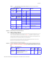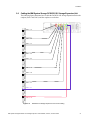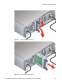
1
IBM System Storage DCS9550 1S1 Storage Expansion Unit Installation, Service, and User Guide SC30-9738-00 The following paragraph does not apply to any country (or region) where such provisions are inconsistent with local law. INTERNATIONAL BUSINESS MACHINES CORPORATION PROVIDES THIS PUBLICATION “AS IS” WITHOUT WARRANTY OF ANY KIND, EITHER EXPRESS OR IMPLIED, INCLUDING, BUT NOT LIMITED TO, THE IMPLIED WARRANTIES OF MERCHANTABILITY OR FITNESS FOR A PARTICULAR PURPOSE. Some states (or regions) do not allow disclaimer of express or implied warranties in certain transactions; therefore, this statement may not apply to you. Order publications through your IBM representative or the IBM branch office serving your locality. No part of this document covered by copyright may be reproduced in any form or by any means—graphic, electronic, or mechanical, including photocopying, recording, taping, or storage in an electronic retrieval system—without prior written permission of the copyright owner. © Copyright International Business Machines Corporation 2007. All rights reserved. US Government Users Restricted Rights – Use, duplication or disclosure restricted by GSA ADP Schedule Contract with IBM Corp. Preface Preface What is in this guide This guide gives you step-by-step instructions on how to install, configure, and connect this product to your host computer. In addition, it provide instructions on how to operate and service this product. Who should use this guide This guide assumes that you have a working knowledge of the Fibre Channel Arbitrated Loop (FC-AL) and Advanced Technology Attachment (ATA) environments into which you are attaching the product. If you do not have these skills, or are not confident with the instructions in this guide, do not proceed with the installation. NOTE : Not all information contained in the following sections will pertain directly to your particular product model. Getting information, help, and service If you need help, service, or technical assistance or just want more information about IBM products, you will find a wide variety of sources available from IBM to assist you. This section contains information about where to go for additional information about IBM and IBM products, what to do if you experience a problem with your IBM System Storage DCS9550 product, and whom to call for service, if it is necessary. Support information For online support information for your IBM System Storage DCS9550 product, visit the following Web site: www.ibm.com/support For telephone support information, in the United States, contact IBM at 1-800-IBM-SERV (426-7378). In other countries, visit the following Web site for support telephone numbers: www.ibm.com/planetwide/ Before you call Before you call, make sure that you have taken these steps to try to solve the problem yourself: • Check all cables on your hardware to make sure that they are connected properly. • Check the power switches to make sure that the system is turned on. • Use the troubleshooting information in your system documentation and use the diagnostic tools that come with your system. Using the documentation Information about the DCS9550 product is available on a documentation CD that comes with your product. You can also access documents using the IBM Publications Center: http://www.ibm.com/shop/publications/order IBM System Storage DCS9550 1S1 Storage Expansion Unit Installation, Service, and User Guide i Preface International Standards This product complies with the requirements of the following agencies and standards: • CE • UL • cUL Qualified Personnel The personnel qualified to use this device are referred to within this document as follows: • Service Person: Someone with the appropriate and necessary technical training and experience to be aware of hazards to which they may be exposed in performing a task and of measures to minimize the risks to that person or other persons. • User/Operator: Any person authorized to handle/operate the product other than a Service Person. Safe Handling Do not try to lift the enclosure by yourself. An enclosure can weigh from 9kg (19.8 lb) to 37kg (77.6lb). Before removing an enclosure from a rack cabinet, always first remove all modules and drives from the enclosure to minimize weight if necessary. Do not try to lift the enclosure by the handles on the PSU/Cooling module. The handles are not designed to support the weight of the populated enclosure. Figure P-1 Weight Handling Label: Lifting and Tipping Figure P-2 Pinch Hazard Label: keep Hands Clear ii IBM System Storage DCS9550 1S1 Storage Expansion Unit Installation, Service, and User Guide Preface Safety Guidelines Caution ! If this product is used in a manner not specified by the manufacturer, the protection provided by the product may be impaired. ! The enclosure MUST be grounded before applying power. Warning ! Unplug the product if you think that it has become damaged in any way and before you move it. Warning Caution ! Plug-in modules are part of the fire enclosure and must only be removed when a replacement can be immediately added. The system must not be run without all units in place. Operate the system with the enclosure top cover closed and blanking plates fitted where modules are missing. To comply with applicable safety, emission, and thermal requirements, keep all enclosure covers securely fitted and keep all bays fitted with plug-in modules. Enclosures must be only operated from a power supply input voltage range of 100 V AC to 240 V AC.When a redundant power input module is fitted, it must be operated from a reduced input voltage range of 200 V AC to 240 V AC. The plug on the power supply cord is used as the main disconnect device. Ensure that the socket outlets are located near the product and are easily accessible. The product is intended to operate with three working Plus. Before removal/replacement of any module disconnect all supply power for complete isolation. To ensure protection against electric shock caused by HIGH LEAKAGE CURRENT (TOUCH CURRENT), the enclosure must be connected to at least two separate and independent Warning sources. This should ensure a reliable earth connection ! IBM System Storage DCS9550 1S1 Storage Expansion Unit Installation, Service, and User Guide iii Preface Figure P-3 PSU/Cooling Module Caution Label: Do not operate with modules missing. A faulty power supply/cooling module must be replaced with a fully operational module within 24 hours. To ensure your system has warning of a power failure, disconnect the power from the PSU by either the switch (where present) or by physically removing the power source, Warning prior to removing the PSU from the enclosure. ! Do not remove a faulty power supply/cooling module unless you have a correct replacement product ready for insertion. Figure P-4 PSU Warning Label (Power Hazards) Always disconnect power to the product prior to removal of the power supply/cooling module from the product chassis. Provide a safe electrical earth (ground) connection for the power cord. Provide a suitable power source with electrical overload protection to meet the requirements detailed in the product’s technical specifications. ! Warning iv Do not remove covers from the Power Supply Unit (PSU). The is the Danger of electric shock. Return the damaged PSU to your supplier for repair. IBM System Storage DCS9550 1S1 Storage Expansion Unit Installation, Service, and User Guide Preface Figure P-5 PSU Safety Label (Electric Shock Hazard Inside) Figure P-6 Redundant Power Input Switch Module Label (Hazardous Voltage) Operation of the product with ANY modules MISSING in the product’s chassis will disrupt airflow and the drives will not receive sufficient cooling. It is ESSENTIAL that all bays in a Warning product chassis are filled before operating the product. ! Figure P-7 I/O Module Caution Label (Do not operate with modules missing) Figure P-8 Drive Carrier Module Caution Label (Drive Spin down time 30 seconds) IBM System Storage DCS9550 1S1 Storage Expansion Unit Installation, Service, and User Guide v Preface Class 1 Laser Product When the product is supplied with optical modules, it contain a laser that complies with Laser Class 1, US 21 QFR (J) & EN 60825-1, UL (NRTL) and TUV. Caution ! If optical modules are to be provided and fitted by the end user, the modules must be a UL (or other North American NRTL) RECOGNISED COMPONENT, must be approved by TUV (or other European Product safety test house), and the laser in the module must comply with Laser Class 1, US 21 QFR (J) & EN 60825-1. Important ! Observe all applicable safety precautions (for example, weight restrictions, handling batteries and lasers etc.) detailed in the preceding paragraphs when dismantling and disposing of this product or its components. Electronic Emission Notices Federal Communications Commission (FCC) Class A Statement IBM is not responsible for any radio or television interference caused by unauthorized changes or modifications to this product. This product complies with Part 15 of the FCC Rules. Operation is subject to the following two conditions: (1) this product must not cause harmful interference, and (2) this product must accept any interference received, including interference that may cause undesired operation. European Union (EU) Electromagnetic Compatibility Directive This product conforms with the protection requirements of EU Council Directive 89/336/EEC on the approximation of the laws of the Member States relating to electromagnetic compatibility. This product has been tested and found to comply with the limits for Class A Information Technology Equipment according to European Standard EN 55022. The limits for Class A equipment were derived for commercial and industrial environments to provide reasonable protection against interference with licensed communication equipment. This is a Class A product. In a domestic environment this product may cause radio interference in which case the user may be required to take adequate measures. European Community contact: IBM Technical Regulations Pascalstr. 100, Stuttgart, Germany 70569 Tele: 0049 (0)711 7851176 Fax: 0049 (0)711 785 1283 e-mail: [email protected] People’s Republic of China Class A Electronic Emission Statement vi IBM System Storage DCS9550 1S1 Storage Expansion Unit Installation, Service, and User Guide Preface Taiwan Class A Electronic Emission Statement Japan VCCI Class A ITE Electronic Emission Statement Industry Canada Class A Emission Compliance Statement This Class A digital product complies with Canadian ICES-003. Avis de conformité à la réglementation d’Industrie Canada Cet appareil numérique de la classe A est conform à la norme NMB-003 du Canada. Germany Electromagnetic Compatibility Directive Zulassungsbescheinigung laut dem Deutschen Gesetz über die elektromagnetische Verträglichkeit von Geräten (EMVG) vom 18. September 1998 (bzw. der EMC EG Richtlinie 89/336). Dieses Gerät ist berechtigt, in Übereinstimmung mit dem Deutschen EMVG das EGKonformitätszeichen - CE - zu führen. Verantwortlich für die Konformitätserklärung nach Paragraph 5 des EMVG ist die: IBM Deutschland Informationssysteme GmbH 70548 Stuttgart. Informationen in Hinsicht EMVG Paragraph 4 Abs. (1) 4:Das Gerät erfüllt die Schutzanforderungen nach EN 55024 und EN 55022 Klasse A. EN 55022 Klasse A Gerate mussen mit folgendem Warnhinweis versehen werden: Warnung: dies ist eine Einrichtung der Klasse A. Diese Einrichtung kann im Wohnbereich Funkstorungen verursachen; in diesem Fall kann vom Betreiber verlangt werden, angemessene Masnahmen durchzufuhren und dafur aufzukommen. Anmerkung: Um die Einhaltung des EMVG sicherzustellen, sind die Gerate wie in den IBM Handbuchern angegeben zu installieren und zu betreiben. IBM System Storage DCS9550 1S1 Storage Expansion Unit Installation, Service, and User Guide vii Preface Korean Class A Electronic Emission Statement l Rack System Precautions The following safety requirements must be considered when the product is mounted in a rack. ! Do not slide more than one product enclosure chassis out of the rack at a time, to avoid the rack from toppling over. Warning ESD Precautions Caution ! It is recommended that you wear a working (examine before wearing) anti-static wrist or ankle strap and observe all conventional ESD precautions when handling Chassis slug-in modules and components. Avoid contact with backplane components, module connectors, etc. Data Security • Before beginning product installation, power down your host computer and all attached peripheral devices. • Disk drives are fragile. Handle them with care, and keep them away from strong magnetic fields. • All the supplied plug-in modules and blanking plates must be in place for the air to flow correctly around the enclosure and to complete the internal circuitry. • If the subsystem is used with modules or blanking plates missing for more than a few minutes, the enclosure can overheat, causing power failure and data loss. • If you remove any drive module, you may lose data. • If you remove a drive module, replace it immediately. Replace it with a drive module of the same type and capacity • Do not abandon your backup routines. No system is completely foolproof. viii IBM System Storage DCS9550 1S1 Storage Expansion Unit Installation, Service, and User Guide Preface Taiwan Contact Information How to Send Your Comments Your feedback is important in helping us to provide the most accurate and high-quality information. If you have comments or suggestions for improving this publication, you can send us comments electronically by using the following address: Internet: [email protected] You can also mail your comments by using the Readers’ Comments Form in the back of this manual or direct your mail to: International Business Machines Corporation Information Development Dept. GZW 9000 South Rita Road Tucson, AZ 85744–0001 U.S.A. IBM System Storage DCS9550 1S1 Storage Expansion Unit Installation, Service, and User Guide ix Preface x IBM System Storage DCS9550 1S1 Storage Expansion Unit Installation, Service, and User Guide Preface xi IBM System Storage DCS9550 1S1 Storage Expansion Unit Installation, Service, and User Guide Contents Contents 1 Introduction ..................................................................................................................................... 1 The IBM System Storage DCS9550 1S1 Storage Expansion Unit 1 1.1.1 1.2.1 1.2.2 1.2.3 1.2.4 1.2.5 1.2.6 1.4.1 1.4.2 1.4.3 1.4.4 1.4.5 1.4.6 1.4.7 1.4.8 1.4.9 1.4.10 Enclosure Chassis .............................................................................................................. 2 Power Supply/Cooling Module ........................................................................................... 3 Operators Panel ................................................................................................................. 4 SCM Input/Output Module .................................................................................................. 5 Drive Carrier Module .......................................................................................................... 8 Dummy Carrier Modules .................................................................................................... 9 Blank Modules .................................................................................................................... 9 Dimensions ....................................................................................................................... 10 Weight .............................................................................................................................. 10 AC Power (450W PSU) .................................................................................................... 10 PSU Safety and EMC Compliance ................................................................................... 10 Power Cord ...................................................................................................................... 10 Environment ..................................................................................................................... 11 Interfaces .......................................................................................................................... 12 SCM I/O Module Specification ......................................................................................... 12 Drive Carrier Module Specification ................................................................................... 12 Software Enclosure Services (SES) Support ................................................................... 13 2 Installation ..................................................................................................................................... 2.1.1 Enclosure Bay Numbering Convention ............................................................................ 2.2.1 Pre-Requisites .................................................................................................................. 2.2.2 Rack Mounting Rail Kit ..................................................................................................... 2.2.3 Chassis Installation .......................................................................................................... 2.3.1 Parts Check List ............................................................................................................... 2.3.2 Power Supply/Cooling Module Procedure ........................................................................ 2.4.1 Internal Loop Structures ................................................................................................... 2.7.1 Procedure ......................................................................................................................... 2.9.1 Planning and Configuring Your Installation ...................................................................... 2.10.1 Parts Check List ............................................................................................................... 2.10.2 Procedure ......................................................................................................................... 2.10.3 Dummy Carrier Modules .................................................................................................. 2.10.4 Engaging the Anti-tamper Locks ...................................................................................... 2.11.1 Parts Check List ............................................................................................................... 2.11.2 Procedure ......................................................................................................................... 15 16 17 17 17 18 18 20 23 26 27 27 29 29 30 30 3 Operation ....................................................................................................................................... 33 3.1.1 Power Supply/Cooling Module LEDs ............................................................................... 34 3.3.1 Disk Drives LEDs ............................................................................................................. 36 4 Troubleshooting and Problem Solving ....................................................................................... 4.2.1 Faulty Cords ..................................................................................................................... 4.2.2 Alarm Sounds On Power Up ............................................................................................ 4.2.3 Green “Signal Good” LED on SCM Not Lit ....................................................................... 4.2.4 Computer Doesn’t Recognize the DCS9550 1S1 Storage Expansion Unit ...................... 4.3.1 Power Supply/Cooling Module ......................................................................................... 37 37 38 38 38 38 xii IBM System Storage DCS9550 1S1 Storage Expansion Unit Installation, Service, and User Guide 4.3.2 4.3.3 4.4.1 4.5.1 4.5.2 4.5.3 4.5.4 4.5.5 4.6.1 4.9.1 4.9.2 4.9.3 4.9.4 xiii Ops Panel ........................................................................................................................ SCM I/O Module LEDs ..................................................................................................... Audible Alarm Mute .......................................................................................................... System Faults .................................................................................................................. Power Supply/Cooling Faults ........................................................................................... Thermal Control ............................................................................................................... Thermal Alarm ................................................................................................................. Thermal Shutdown ........................................................................................................... Dummy Carrier Modules .................................................................................................. Power Supply/Cooling Modules ....................................................................................... Ops Panel ........................................................................................................................ SCM I/O Module .............................................................................................................. Drive Carrier Module ........................................................................................................ 39 41 41 42 42 43 44 44 45 46 48 48 50 Introduction 1 Introduction 1.1 The IBM System Storage DCS9550 1S1 Storage Expansion Unit . Figure 1–1 The DCS9550 SATA Disk Chassis Model 1S1 System The DCS9550 1S1 Storage Expansion Unit design concept is based on a subsystem together with a set of plug-in modules. The DCS9550 1S1 Storage Expansion Unit subsystem as supplied comprises: • Chassis and Backplane with integral.Operators Panel.(See Figure 1–8) • Up to 16 Serial ATA (SATA) Drive Carrier modules (See Figure 1–9) – Serial ATA (SATA) drives with appropriate switching card. IBM System Storage DCS9550 1S1 Storage Expansion Unit Installation, Service, and User Guide 1 Introduction • Dummy drive carrier modules. • Two AC, 450W Power Supply/Cooling plug-in modules (see Figure 1–4) • One or two Serial ATA Control (SCM) Input/Output modules, dependent on configuration required: 1.5Gb internal operating speed with 1 Gb or 2Gb external operating speed. (See Figure 1–6). 1.1.1 Enclosure Chassis The chassis consists of a sheet metal enclosure assembly containing a Backplane PCB and module runner system This chassis assembly also includes an integral Operators (Ops) Panel, mounted at the rear. The chassis assembly contains 16 drive bays at the front, each of which accommodates a plug-in drive carrier module. The 16 drive bays are arranged in 4 rows of 4 drives. At the rear, the chassis assembly contains the integral ops panel and four module bays to house two Power Supply/Cooling modules, one SCM I/O module, and one blank SCM module filler. The Backplane PCB provides logic level signal and low voltage power distribution paths. Figure 1–2 and Figure 1– 3 show front and rear views of an RS-1602 chassis respectively. Note The DCS9550 1S1 Storage Expansion Unit is shipped in a preconfigured 42U rack configuration, except for the top three in the rack with the controllers or top two in an expansion rack. Refer to the IBM System Storage DCS9550 Installation, Service, and User Guide. . Figure 1–2 Enclosure Chassis (Front) Figure 1–3 Enclosure Chassis (Rear) . 2 IBM System Storage DCS9550 1S1 Storage Expansion Unit Installation, Service, and User Guide Introduction 1.2 The Plug-in Modules An DCS9550 1S1 Storage Expansion Unit requires one or more of the following modules for normal operation: 1.2.1 Power Supply/Cooling Module Two auto ranging AC 450WPower Supply/Cooling modules (Figure 1–4) are supplied mounted in the rear of the enclosure as part of the subsystem core product. Figure 1–4 . AC Power Supply/Cooling Module PSU voltage operating ranges are nominally 115V or 230V AC, selected automatically. . Four LEDs mounted on the front panel of the Power Supply/Cooling module (see Figure 2–1) indicate the status of the PSU and the fans. 1.2.1.1 Multiple Power Supply/Cooling Modules The DCS9550 1S1 Storage Expansion Unit must always be operated with two Power Supply/Cooling modules fitted. The two Power Supply/Cooling modules operate together so that if one fails the other maintains the power supply and cooling while you replace the faulty unit. Module replacement should only take a few minutes to perform but must be completed within 10 minutes from removal of the failed module. IBM System Storage DCS9550 1S1 Storage Expansion Unit Installation, Service, and User Guide 3 Introduction 1.2.2 Operators Panel Supplied as an integral part of the Enclosure core product, a typical Operators (Ops) Panel is shown in Figure 1–5. Figure 1–5 Ops Panel The Ops Panel provides the enclosure with a micro controller which is used to monitor and control all elements of the Enclosure. 1.2.2.1 Ops Panel Indicators and Switches The Ops Panel includes Light Emitting Diodes (LEDs) which show the status for all modules, an Audible Alarm which indicates when a fault state is present, a push-button Alarm Mute Switch and a thumb wheel Enclosure ID Switch. The Ops Panel switch functions are shown in Table 1–1. Table 1–1 Ops Panel Switch Functions (Default settings for DCS9550 1S1 Storage Expansion UnitSCM usage at 2Gb/s) Switch Number Function *See Sw 11 4 Recommended Setting 1 Not Used Off 2 Not Used Off 3 Not Used Off 4 Not Used Off 5 Not Used Off 6 Not Used Off Definition IBM System Storage DCS9550 1S1 Storage Expansion Unit Installation, Service, and User Guide Introduction Table 1–1 Ops Panel Switch Functions (Default settings for DCS9550 1S1 Storage Expansion UnitSCM usage at 2Gb/s) Switch Number Function *See Sw 11 Drive Loop Speed Select Recommended Setting Definition Sw 7 Sw 8 DCS9550 Controller Settings Off Off Force 1Gb/s DCS9550 Controller Settings On Off Force 2Gb/s (recommended) Sw 9 Sw 10 Off On Mode 1 On On Mode 0 On Off Mode 2 Off Off Mode 3 (not supported)* 7&8 Drive Addressing Mode Selection 9 & 10 DCS9550 Controller Settings 11 12 SOFT SELECT On Not Used Off Selects functions using the hardware switches Note: * Please contact your supplier for further information. Important 1.2.3 Switch settings are only read at Power On. SCM Input/Output Module The DCS9550 1S1 Storage Expansion Unit includes an enclosure with rear facing bays which houses one or two SATA Control Interface Adaptor (SCM I/O) modules (see Figure 1–3), dependent on configuration required. The plug-in SCM I/O modules have been designed for integration into a DCS9550 1S1 Storage Expansion Unit, providing external FCAL cable interfacing with up to 16 SATA disk drives. Processors housed on the SCM I/O modules provide enclosure management and interface to devices on the Backplane, PSU, SCM and Ops Panel, to monitor internal functions. The module incorporates the following LED indicators: Host Important If only one SCM module is fitted, the SCM module must be installed in Rear Bay 4 location [see Figure 1–3, ”Enclosure Chassis (Rear)”, on page 2] and a Blank I/O module fitted in the unused bay. Table 1–2 SCM I/O Module LEDs LED Definition Color FC Host Port 0 Signal Good Incoming FC signal is GOOD No connection or incorrect connection Invalid SFP connection Green IBM System Storage DCS9550 1S1 Storage Expansion Unit Installation, Service, and User Guide Normal Status On Fault Status Off Flashing 5 Introduction Table 1–2 FC Host Port 1 Signal Good Incoming FC signal is GOOD No connection or incorrect connection Invalid SFP connection Green Router Status Storage Router Device Ready Storage Router Device not ready or defective Green ESI/SCM Module Fault Fault present (also On when booting) Successful controller initialization Amber Figure 1–6 6 SCM I/O Module LEDs On Off Flashing On Off Off On SCM I/O Module IBM System Storage DCS9550 1S1 Storage Expansion Unit Installation, Service, and User Guide Introduction Figure 1–7 SCM Front Panel (as viewed from rear of Enclosure) Figure 1–8 DCS9550 1S1 Storage Expansion Unit with SCM I/O Modules Installed IBM System Storage DCS9550 1S1 Storage Expansion Unit Installation, Service, and User Guide 7 Introduction 1.2.4 Drive Carrier Module The Drive Carrier Module comprises a hard disk mounted in a carrier. Each drive bay can house a single Low Profile 1.0 inch high, 3.5 inch form factor disk drive in its carrier. The carrier has mounting locations for ATA or FC-AL drives. Each disk drive is enclosed in a die-cast aluminum carrier which provides excellent thermal conduction, radio frequency, and electro-magnetic induction protection and affords the drive maximum physical protection. The front cap also supports an ergonomic handle which provides the following functions: • Camming of carrier into and out of drive bays. • Positive 'spring loading' of the drive/backplane connector. • An anti-tamper lock operated by a torx socket type key. Figure 1–9 1.2.4.1 Drive Carrier Module SATA Dual Path Transition Card For SATA drives, a SATA dual path transition card is used in place of a SATA - PATA transition card. This is attached to the rear of each drive to provide a SCA-2 interface to the drive carrier using the same pins as Fibre Channel. In addition, the card provides a SATA path switch (1.5Gb/s) suitable for dual redundant I/O module applications. 1.2.4.2 Drive Status Indicators Each drive carrier incorporates two indicators, an upper (Green) and lower (Amber). In normal operation the green indicator will be ON and will flicker as the drive operates.The amber indicator is OFF during normal operation and ON if there is a drive fault present. 8 IBM System Storage DCS9550 1S1 Storage Expansion Unit Installation, Service, and User Guide Introduction 1.2.4.3 Anti-tamper Locks Anti-tamper locks are fitted in the drive carrier handles (Figure 1–10) and are accessed through the small cutout in the latch section of the handle.These are provided to disable the normal ‘pinch' latch action of the carrier handle and so prevent accidental or unauthorized removal of drives. Figure 1–10 1.2.5 Anti-tamper Lock Dummy Carrier Modules Dummy carrier modules are provided for fitting in all unused drive bays. They are designed as integral drive module front caps with handles and must be fitted to all unused drive bays to maintain a balanced airflow. 1.2.6 Blank Modules Blank SCM I/O modules must be fitted in the vacant SCM bay (slot 3) at the rear of the enclosure (Figure 1–3 on page 2 refers) to maintain airflow and ensure correct operation. ATTENTION Operation of the Enclosure with ANY modules missing will disrupt the airflow and the drives will not receive sufficient cooling. It is ESSENTIAL that all apertures are filled before operating the unit. Dummy Carriers and/or Blank modules are available for this purpose. 1.3 Visible and Audible Alarms The functional modules have associated status LEDs. The Ops Panel shows a consolidated status for all modules. LEDs show constant green for good or positive indication. Constant Amber LEDs indicate there is a fault present within that module. The Ops Panel also incorporates an Audible Alarm to indicate when a fault state is present and also an Alarm Mute push-button. ATTENTION The Ops Panel is an integral part of the enclosure chassis assembly and is not field replaceable. IBM System Storage DCS9550 1S1 Storage Expansion Unit Installation, Service, and User Guide 9 Introduction 1.4 DCS9550 1S1 Storage Expansion Unit Technical Specification 1.4.1 Dimensions Rack Enclosure 1.4.2 1.4.3 1.4.4 inches millimeters Height 5.12 130 Width across mounting flange 19.0 482 Depth 19.7 500 Weight Fully loaded with 16 drives 37kg (77.6 lb) Empty Enclosure 9kg (19.8lb) AC Power (450W PSU) Voltage Range 100-120 / 200-240 VAC Rated Voltage Range Selection Automatic Frequency 50/60 Hz Inrush Current 50A @ 260VAC Power Factor >0.98 Harmonics Meets EN61000-3-2 PSU Safety and EMC Compliance Safety Compliance UL 60950 IEC 60950 EN 60950 EMC Compliance CFR47 Part 15B Class A EN55022 EN55024 1.4.5 Power Cord (minimum requirements) Cord Type 10 SV or SVT, 18 AWG minimum, 3 conductor Plug 250V, 10A Socket IEC 320 C-14, 250V, 15A IBM System Storage DCS9550 1S1 Storage Expansion Unit Installation, Service, and User Guide Introduction 1.4.6 Environment Table 1–3 Ambient Temperature and Humidity Temperature Range Relative Humidity Max. Wet Bulb Operational 5°C to 40°C 20% to 80% non-condensing 23°C Non-Operational 0°C to +50°C 8% to 80% non-condensing 27°C Storage 1°C to +60°C 8% to 80% non-condensing 29°C Shipping -40°C to +60°C 5% to 100% non-precipitating 29°C Airflow System must be operated with low pressure rear exhaust installation (Back pressure created by rack doors and obstacles not to exceed 5 pascals [0.5mm Water gauge]) Altitude, Operational 0 to 2133 m (0 to 7,000ft) (10,000ft at maximum ambient of 35°C) Altitude, Non-Operational -305 to 12,192m (-1000 to 40,000ft) Shock, Operational Vertical axis 5g peak 1/2 sine, 10ms Shock, Non-Operational 30g 10ms 1/2 sine Vibration, Operational 0.21grms 5-500 Hz Random Vibration, Non-Operational 1.04grms 2-200 Hz Random Vibration, Relocation 0.3g 2-200 Hz sine Acoustics Less than 6.0 LwA Orientation & Mounting 19" Rack mount (3EIA Units) • Rack Rails To fit 800mm depth Racks compliant with IEC 297 • Rack Characteristics Back pressure not exceeding 5 pascals (0.5mm water gauge) Safety & Approvals CE, UL, cUL IBM System Storage DCS9550 1S1 Storage Expansion Unit Installation, Service, and User Guide 11 Introduction EN55022 (CISPR - A), FCC A • EMC 1.4.7 Interfaces Drive support See drive carrier specification Attachment 1 FCAL loop of 16 drives Passive Backplane with 1 or 2 Loop Resiliency Circuit (SCM) I/O Modules. Host Port: FC-AL SFP - SFP cables Maximum external cable length: see manufacturer’s specification Expansion Port: SFP to SFP cables 1.4.8 SCM I/O Module Specification Speed 1.5Gb/s internal to each drive, 1Gb/s or 2Gb/s external • Creates connections to a single loop of 16 drives Mounting Rear, single bays 3 and/or 4 (see Figure 1–3) • 1 External FC loop with two SFP connections Connectors • 2 x Expansion Ports: SFP connector • 2 x Host Ports: SFP connector (2 per port) LED Functions FC Host Port 0 Signal Good – Green: On: Incoming FC signal is GOOD – Off: no connection or incorrect connection – Flashing: Invalid SFP connection FC Host Port 1 Signal Good – Green: On: Incoming FC signal is GOOD – Off: no connection or incorrect connection – Flashing: Invalid SFP connection Router Status – Green: On: Storage Router Device Ready – Off: Storage Router Device not ready or defective ESI/SCM Module Fault – Amber: On: Fault present (also On when booting) – Off: successful controller initialization Power Dissipation 1.4.9 20W max. Drive Carrier Module Specification Please contact your supplier for details of approved drives. Important Operating the DCS9550 1S1 Storage Expansion Unit with non-approved drives may invalidate the warranty. Module Dimensions Height 29.1mm Width 106.55mm Depth 44 mm Weight 0.98kg (1.0” 36Gb drive) Transition card mounting locations for ATA - SATA drives with transition card attached Operating Temperature 5° C to 40° C (when installed in an RS-1602 system enclosure with dual Power Supply/Cooling Modules) Power Dissipation 12 17 Watts maximum IBM System Storage DCS9550 1S1 Storage Expansion Unit Installation, Service, and User Guide Introduction 1.4.10 Software Enclosure Services (SES) Support The enclosure has a sophisticated self-monitoring and reporting function which conforms to ANSI SES specifications.This reports on such topics as: • • • • Enclosure temperature Fan speed Drive condition Operator panel status IBM System Storage DCS9550 1S1 Storage Expansion Unit Installation, Service, and User Guide 13 Introduction This page is intentionally blank. 14 IBM System Storage DCS9550 1S1 Storage Expansion Unit Installation, Service, and User Guide Installation 2 Installation In this chapter, you are shown how to install your DCS9550 1S1 Storage Expansion Unit and plug-in modules into an industry standard 19 inch rack cabinet. Caution 2.1 When connecting up the DCS9550 1S1 Storage Expansion Unit, use only the power cords supplied or cords which match the specification quoted in section 1.4.5. Planning Your Installation Before you begin installation you should become familiar with the configuration requirements of your DCS9550 1S1 Storage Expansion Unit, detailed in Table 2–1. The correct positions of each of the optional plug-in modules are shown in Table 2–1. Please refer to sections 2.4 - 2.7 for details of SCM I/O module configurations and installation. Table 2–1 DCS9550 1S1 Storage Expansion Unit Configuration Module Location Drive Bays ALL drive bays must be fitted with either a drive carrier module or a dummy carrier, no bays should be left completely empty. Drive carrier modules 0 & 15 provide SES Management Services. Power Supply/ Cooling Modules Two Power Supply/Cooling modules must be fitted. Full power and cooling redundancy is provided while a faulty module is replaced. Install the Power Supply/Cooling modules in rear Bays 1 and 5. Note: Rear bays are numbered from 1 to 5 commencing from the right side. SCM I/O Module One SCM module should be installed in rear Bay 3. A blank module is fitted rear Bay 4. IBM System Storage DCS9550 1S1 Storage Expansion Unit Installation, Service, and User Guide 15 Installation Table 2–1 DCS9550 1S1 Storage Expansion Unit Configuration Module Location Blank SCM I/O Modules Install in rear Bay 4. Ops Panel (integral part of chassis assembly). Installed in rear Bay 2. Caution Figure 2–1 2.1.1 Dummy Carriers and Blank Modules MUST be fitted to ALL unused bays. There is inadequate drive cooling if any are left open. Module locations Enclosure Bay Numbering Convention The enclosure bay numbering convention is shown in Figure 2–1. A bay is defined as the space required to house a single 1.0 inch high 3.5 inch disk drive in its carrier module. For example, a 1 x 4 bay module would take the space of 1 drive width by 4 drive bays high (in the rack mount configuration). The DCS9550 1S1 Storage Expansion Unit is housed in a 4 x 4 enclosure, that is, 4 bays wide by 4 bays high. • The front bays are numbered 1 to 4 from left to right, as viewed from the front. Bays are numbered from 1 (top row) to 4 (bottom row). Drive Carrier Module locations are identified from a matrix of the top and side numbers. • The rear bays are numbered 1 to 5 from right to left, as viewed from the rear. 16 IBM System Storage DCS9550 1S1 Storage Expansion Unit Installation, Service, and User Guide Installation 2.2 Enclosure Installation Procedures Caution ! Warning 2.2.1 The DCS9550 1S1 Storage Expansion Unit with all its component parts installed is too heavy for a single person to easily install into a Rack cabinet. The following procedures describe the installation of the DCS9550 1S1 Storage Expansion Unit and highlights any critical co-requisite requirements and good handling practices which you should follow so as to ensure that a successful installation is achieved in the easiest manner. Ensure that you have fitted and checked a suitable anti-static wrist or ankle strap and observe all conventional ESD precautions when handling DCS9550 1S1 Storage Expansion Unit modules and components. Avoid contact with Backplane components and module connectors, etc. Pre-Requisites The DCS9550 1S1 Storage Expansion Unit is designed for installation into an industry standard 19 inch cabinet capable of holding the unit. • Minimum depth: 500 mm from front flange to rear metalwork (excludes rear cabling). • Weight: up to 37kg dependent upon configuration per enclosure. • Clearances: a minimum gap of 25mm (1inch) clearance between the rack cover and front of drawer; and 50mm (2 inches) rear clearance between rear of drawer and rear of rack is recommended in order to maintain the correct air flow around the enclosure. • Maximum back pressure: The rack should present a maximum back pressure of 5 pascals (0.5mm water gauge). 2.2.2 Rack Mounting Rail Kit A set of mounting rails is available for use in 19 inch rack cabinets. These rails have been designed and tested to handle the maximum enclosure weight and to ensure that multiple DCS9550 1S1 Storage Expansion Unit may be installed without loss of space within the rack. Use of other mounting hardware may cause some loss of rack space. 2.2.2.1 Parts Check List • Rack Mounting Rail Kit 2.2.3 2.2.3.1 Chassis Installation Parts Check List • Chassis (complete with Backplane and Ops Panel installed but excluding all plug-in modules). IBM System Storage DCS9550 1S1 Storage Expansion Unit Installation, Service, and User Guide 17 Installation • Rack mount front flange mounting screws (4 off). 2.2.3.2 Procedure 1 Check for damage. 2 Slide the chassis assembly onto the rack rails until the front flanges engage on the rack. 3 Ensure the chassis is centrally located. If in doubt about correct orientation, the drive bays (at front) should have their black drive connectors toward the bottom of each bay. 4 Screw the 4 front rack mount screws through the flanges and tighten. 5 Fit and tighten the rear hold down screws ensuring the enclosure is in tight contact to both the side and top of the chassis to avoid any movement of the chassis in the rack. 2.3 Power Supply/Cooling Module Installation • Two power supply/cooling modules to be installed in the rear of the enclosure in positions 1 and 5. Do not remove covers from the power supply unit. Danger of electric shock inside. Return the PSU to Customer Service for repair. ! Warning 2.3.1 Parts Check List • 2 x AC, 450W Power Supply/Cooling Modules 2.3.2 Power Supply/Cooling Module Procedure Important 1 Check for damage, especially to the rear connector on the supply. Caution 2 18 PSU1 (RH rear bay) must be fitted “upside-down”(Figure 2–1). If necessary, reorient the power cord clip so that the power cord can be properly retained. Handle the module carefully and avoid damaging the connector pins. Do not install the module if any pins appear to be bent. With the PSU handle in the open position (Figure 2–2), slide the module into the enclosure (Figure 2–3). IBM System Storage DCS9550 1S1 Storage Expansion Unit Installation, Service, and User Guide Installation Important Install the Power Supply/Cooling module (PSU 0) in the bay on the right side (Rear Bay 1) of the enclosure in an “upside down” orientation. If necessary, reorient the power cord clip so that the power cord can be properly retained. 3 Cam the module home by manually closing the PSU handle (Figure 2–4). You should hear a click as the handle latches engage. 4 Connect the power supply cord to the power source and switch the power supply ON. Figure 2–2 AC Power Supply/Cooling Module - Handle in Open Position Figure 2–3 Installing an AC Power Supply Cooling Module (1) IBM System Storage DCS9550 1S1 Storage Expansion Unit Installation, Service, and User Guide 19 Installation Figure 2–4 2.4 Installing an AC Power Supply Cooling Module (2) SCM I/O Module Configurations Important 2.4.1 Please refer to section 2.9 for information on SATA drive configurations. Internal Loop Structures The DCS9550 1S1 Storage Expansion Unit is configured with one internal loop of 16 drives. 2.5 FC-AL Interface The SCM (I/O) interface module provides an external FC-AL interface via SFP connection.The SCM module facilitates the emulation of fibre channel drives by ATA/SATA drives by converting FC protocols to ATA/SATA protocols. This is done through protocol conversion on the SCM module, which directly connects to each drive using the serial ATA protocol and then presents to the host via one FC loop hubbed to two or four SFP connections, depending on configuration. Note 20 There are no external terminators required with Fibre Channel architecture and any drive may be hot plugged during operation. IBM System Storage DCS9550 1S1 Storage Expansion Unit Installation, Service, and User Guide Installation 2.6 Cabling the IBM System Storage DCS9550 1S1 Storage Expansion Unit The following figures illustrates how to cable the DCS9550 1S1 Storage Expansion Unit to the couplets (Unit 1 and Unit 2) and the couplets to each other. Unit 1—A Unit 1—B Unit 1—C Unit 1—D Unit 1—E Unit 1—F Unit 1—G Unit 1—H Unit 1—P Unit 1—S Figure 2–5 DCS9550 1S1 Storage Expansion Unit: Unit #1 Cabling IBM System Storage DCS9550 1S1 Storage Expansion Unit Installation, Service, and User Guide 21 Installation Unit 2— A Unit 2— B Unit 2— C Unit 2— D Unit 2— E Unit 2— F Unit 2— G Unit 2— H Unit 2— P Figure 2–6 Unit 2— S 22 DCS9550 1S1 Storage Expansion Unit: Unit #2 Cabling IBM System Storage DCS9550 1S1 Storage Expansion Unit Installation, Service, and User Guide Installation Figure 2–7 IBM System Storage DCS9550 Couplet Cabling 2.7 SCM I/O Module Installation Important 2.7.1 The SCM I/O modules must be installed in Rear Bay 3 and 4 location [see Figure 2–1, ”Module locations”, on page 16]. Procedure Check for damage especially to the interface connector. Do not install if any pins are bent. Figure 2–8 SCM Module Latch Operation 1 Install the module in rear Bay 3 of the enclosure (Figure 2–1). 2 With the latch in the open position (see Figure 2–8), slide the SCM module into the enclosure until the latch engages automatically. 3 Cam the module home by manually closing the latches (see Figure 2–9). You should hear a click as the latch engages. IBM System Storage DCS9550 1S1 Storage Expansion Unit Installation, Service, and User Guide 23 Installation Figure 2–9 2.8 Installing an SCM I/O Module in Bay 4 Drive Enclosure Device Addressing Each enclosure has 16 drive bays. The SEL_ID of each drive is determined by the device slot (0-15) in which it is installed and the address range setting, which is set by means of the Enclosure ID switch on the Ops Panel (shown in Figure 1–2 on page 2) at the rear of the enclosure. The switch settings are shown in Table 2–2 Table 2–2 Ops Panel Switch Functions (Default settings for DCS9550 1S1 Storage Expansion Unit SCM usage at 1Gb/s) Switch Number Function Recommended Setting 1 thru 6 Not Used Off 7&8 Drive Loop Speed Select Sw 7 Sw 8 On Off DCS9550 Controllers 9 & 10 Drive Sw 9 Addressing Mode Selection DCS9550 Controllers 24 Off Definition Force 2Gb/s Sw 10 On Mode 1 IBM System Storage DCS9550 1S1 Storage Expansion Unit Installation, Service, and User Guide Installation Table 2–2 Ops Panel Switch Functions (Default settings for DCS9550 1S1 Storage Expansion Unit SCM usage at 1Gb/s) Switch Number Function 11 SOFT SELECT On 12 Not Used Notes Recommended Setting Definition Selects functions using the hardware switches Off 1 ON = switch to the left, OFF = switch to the right. Table 2–3 Mode 1 Drive Addressing Thumb Device Slot SEL_ID Wheel Mode 1 Switch 0 0 1 2 3 4 5 6 7 8 9 10 11 12 13 14 15 NOTE: Thumbwheel switch setting 0 causes a blinking amber LED indicating an invalid ID condition; however, actual addressing is as stated. 1 0 1 2 3 4 2 16 17 18 19 20 3 32 33 34 4 5 6 21 22 7 8 9 10 11 12 13 14 15 23 24 25 26 27 28 29 30 31 35 36 37 38 39 40 41 42 43 44 45 46 47 48 49 50 51 52 53 54 55 56 57 58 59 60 61 62 63 5 64 65 66 67 68 71 72 73 74 75 76 77 78 79 6 80 81 82 83 84 85 87 88 90 91 92 93 94 95 7 96 97 98 99 100 101 102 103 104 105 106 107 108 109 110 111 8 96 97 98 99 100 101 102 103 104 105 106 107 108 109 110 111 9 96 97 98 99 100 101 102 103 104 105 106 107 108 109 110 111 10 96 97 98 99 100 101 102 103 104 105 106 107 108 109 110 111 11 96 97 98 99 100 101 102 103 104 105 106 107 108 109 110 111 12 96 97 98 99 100 101 102 103 104 105 106 107 108 109 110 111 13 96 97 98 99 100 101 102 103 104 105 106 107 108 109 110 111 14 96 97 98 99 100 101 102 103 104 105 106 107 108 109 110 111 15 96 97 98 99 100 101 102 103 104 105 106 107 108 109 110 111 69 70 65 89 IBM System Storage DCS9550 1S1 Storage Expansion Unit Installation, Service, and User Guide 25 Installation ) Table 2–4 Drive Slot Arrangement: Enclosure Front View Row/ Column 1/# 2/# 3/# 4/# #/1 Drive 0* Drive 1 Drive 2 Drive 3 #/2 Drive 4 Drive 5 Drive 6 Drive 7 #/3 Drive 8 Drive 9 Drive 10 Drive 11 #/4 Drive 12 Drive 13 Drive 14 Drive 15* Notes 1 Drives are numbered row/column. 2 With only one active PSU the enclosure takes approximately 96 seconds to start all drives from Power On. 3 * Denotes SES drives which should always be fitted. 2.9 2.9.1 2.9.1.1 Drive Carrier Configuration Planning and Configuring Your Installation System Configuration Important Before you begin installation you should become familiar with the configuration requirements of your DCS9550 1S1 Storage Expansion Unit. Please refer to Section 2.1 for information on your overall system configurations. There must be a drive present in Bay 1/1 (drive 0) or 4/4 (drive 15) to enable SES Communications to operate. Installing drives in both of these bays provides redundant SES communication paths. When planning your system configuration, please remember that: • All DCS9550 1S1 Storage Expansion Unit drive bays must be filled with either a drive carrier or front dummy fascia. No bays should be left completely empty. 2.9.1.2 Drive Configuration Important 26 After you have installed the drive carrier modules in your DCS9550 1S1 Storage Expansion Unit, please refer to Section 2.4 for configuration information relevant to the I/O module you are installing. IBM System Storage DCS9550 1S1 Storage Expansion Unit Installation, Service, and User Guide Installation 2.10 2.10.1 Drive Carrier Installation Parts Check List • Drive Carrier module, or • Dummy Carrier module 2.10.2 Procedure 1 Ensure that the anti-tamper lock is disengaged. 2 Release the carrier handle by pressing the latch in the handle towards the right. 3 Insert the carrier into the enclosure (Figure 2–10). Important 4 For a Rack Mounted System: Ensure that the carrier is oriented so that the drive is uppermost and the handle opens from the left. Slide the carrier, gently, all the way into the enclosure until it is stopped by the camming lever on the right of the carrier (Figure 2–11). Cam the carrier home - the camming foot on the base of the carrier engages into a slot in the enclosure. Continue to push firmly until the handle fully engages. You should hear a click as the latch engages and holds the handle closed (Figure 2–12). Note Ensure that the Handle always opens from the left. IBM System Storage DCS9550 1S1 Storage Expansion Unit Installation, Service, and User Guide 27 Installation 28 Figure 2–10 Installing a SATA Drive Carrier Module (1) Figure 2–11 Installing a SATA Drive Carrier Module (2) IBM System Storage DCS9550 1S1 Storage Expansion Unit Installation, Service, and User Guide Installation Figure 2–12 Installing an SATA Drive Carrier Module (3) Note 2.10.3 Removal is the reverse of this procedure (press on the latch to release the handle). Dummy Carrier Modules Any unused drive bays must be fitted with a dummy carrier module. 2.10.4 Engaging the Anti-tamper Locks The anti-tamper locks are fitted in the drive carrier handles and are accessed through the small cutout in the latch section of the handle. Drives are supplied with the locks set in the locked position. 2.10.4.1 Activating the Locks 1 Carefully insert the lock key provided into the cutout in the handle. 2 Locate the key into its socket. 3 Rotate the key in a clockwise direction until the indicator is visible in the aperture beside the key. IBM System Storage DCS9550 1S1 Storage Expansion Unit Installation, Service, and User Guide 29 Installation ). Figure 2–13 4 Activating the Anti-tamper Lock Remove the key. De-activation is the reverse of this procedure. To deactivate, rotate the key in an anticlockwise direction until the indicator is no longer visible in the aperture beside the key. Note 2.11 2.11.1 A drive carrier cannot be installed if its anti-tamper lock is activated outside the enclosure. Power Cord Connection Parts Check List • Power cord to requisite local standards 2.11.2 Procedure 1 Attach the power cord to the Power Supply/Cooling Modules. 2 Attach the power cord to the in-line IEC connector in this cord. 3 Switch on each Power Supply/Cooling Module. The PSU Good and AC Fail LEDs on the PSU indicate whether AC mains power is present. Caution 30 The power connections must always be disconnected prior to removal of the Power Supply/Cooling module from the enclosure. IBM System Storage DCS9550 1S1 Storage Expansion Unit Installation, Service, and User Guide Installation 2.12 Grounding Checks The product must only be connected to a power source that has a safety electrical earth connection. Warning If more than one product is fitted in a rack, the earth connection to the rack is even more important, because the rack will then have a high “EARTH LEAKAGE CURRENT” (“TOUCH CURRENT”). The earth connection to the rack must be checked before switching on by an electrical engineer who is qualified to the appropriate local and national standards to perform the check. IBM System Storage DCS9550 1S1 Storage Expansion Unit Installation, Service, and User Guide 31 Installation This page is intentionally blank. 32 IBM System Storage DCS9550 1S1 Storage Expansion Unit Installation, Service, and User Guide Operation 3 Operation Before powering up the enclosure please ensure that all the modules are firmly seated in their correct bays. 3.1 Power On Caution Do not operate the subsystem until the ambient temperature is within the specified operating range. If the drives have been recently installed ensure they have had time to acclimatize before operating them. Note Please refer to Section h2-Heading for details of the Ops Panel LEDs and related fault conditions. Follow the procedure below to Power On the enclosure. 1 Apply AC Mains power to the enclosure. Turn the Power Supply modules to ON. 2 On the Ops Panel, the Audible Alarm beeps once, all LEDs flash for 7 seconds then the Alarm double beeps. 3 All LEDs on the Ops Panel should be lit (Green) when the enclosure power is activated (and the disk drive motors should start). Note All LEDs on the Ops Panel should be lit Green at power up to indicate that the system is functioning correctly. If any show Amber then a problem exists. If mains power is lost for any reason, on restoration of power the enclosure will re-start automatically. IBM System Storage DCS9550 1S1 Storage Expansion Unit Installation, Service, and User Guide 33 Operation 3.1.1 Power Supply/Cooling Module LEDs The Power Supply/Cooling module incorporates 4 LEDs, located below the On/Off switch and shown in tablecap. • Under Normal conditions the LEDs should all be illuminated constant GREEN • If a problem is detected the color of the relevant LED will change to AMBER. Table 3–1 PSU LEDs AC PSU PSU Good Green AC input Fail Amber 34 Fan Fault Amber DC Output Fail Amber IBM System Storage DCS9550 1S1 Storage Expansion Unit Installation, Service, and User Guide Operation 3.2 Ops Panel LEDs The Ops Panel LEDs fault and status conditions are defined in Table 3-2 and shown in Figure 3-1. Figure 3–1 Ops Panel LEDs and Switches Please refer to Chapter 4, Troubleshooting and Problem Solving for details of any fault indication. Table 3–2 Ops Panel LED States LED Definition Color Normal Status Fault Status Invalid Address Indicates that an invalid Enclosure ID has been selected or that the selection has changed after Power On Amber Off Flashing Power On Enclosure Powered On Green On Off System Fault System/SCM Fault Amber Off On PSU/Cooling Fault PSU Cooling fault or enclosure over-temperature. Amber Off On IBM System Storage DCS9550 1S1 Storage Expansion Unit Installation, Service, and User Guide 35 Operation Table 3–2 Ops Panel LED States 3.3 LED Definition Color Normal Status Fault Status 2Gb Link Speed Indicates link speed Green Off On Hub Mode Not Used Green Off Off Starting the Drives Unless otherwise selected during installation, all drives in the enclosure should automatically start their motors. If this has not occurred one of the following conditions may exist: • There may be a power problem (an alarm and power fault indication would normally be active). • If there is only one Power Supply/Cooling Module present, the drive motors will spin up in a delayed sequence. 3.3.1 Disk Drives LEDs Each drive carrier incorporates two indicators, an upper (GREEN) and lower (AMBER). In normal operation the Green LED will be ON and will flicker as the drive operates.The amber indicator is OFF during normal operation and ON if there is a drive fault present. 3.4 Power Down To power the Enclosure down, either • Switch off the Power Supply/Cooling modules installed in the Enclosure. or • Remove AC Mains at the power source 36 IBM System Storage DCS9550 1S1 Storage Expansion Unit Installation, Service, and User Guide 4 Troubleshooting and Problem Solving The DCS9550 1S1 Storage Expansion Unit includes a processor and associated monitoring and control logic to enable it to diagnose problems within the enclosure’s power, cooling and drive systems. The Enclosure Services Processor is housed along with the Ops Panel in the rear of the enclosure. The sensors for power and cooling conditions are housed within the Power Supply/Cooling modules. There is independent monitoring for each unit. If a fault is indicated on the Ops Panel, please refer to Table 4–2. 4.1 Emulation Limitations Each SCM presents each SATA disk drive as a single ported FC device. However unlike real FC-AL device certain data such as emulated WWN is not available on Power On, so the emulated devices will not present on the FC loop and participate in FC loop initialization until the drive has spun up. Please note that your RAID Head/Host system needs to be aware of this extra spin up time during Power On situations, whether they be planned ON or NOT ON (e.g. as the result of an unexpected power interrupt). Where some features, such as mode pages are not directly supported these will be emulated by the device, but changing these mode pages may not cause a change in the drive’s behavior, Where an equivalent function exists, e.g. SMART data, the ATA SMART data will be presented to the Host through the CF SCSI command set. 4.2 4.2.1 Initial Start-up Problems Faulty Cords First check that you have wired up the subsystem correctly. Then, if: • cords are missing or damaged • plugs are incorrect • cords are too short Call your supplier for a replacement. IBM System Storage DCS9550 1S1 Storage Expansion Unit Installation, Service, and User Guide 37 Troubleshooting and Problem Solving 4.2.2 Alarm Sounds On Power Up Please refer to Section 4.4. 4.2.3 Green “Signal Good” LED on SCM Not Lit Check that the cables have not been reversed during installation. 4.2.4 Computer Doesn’t Recognize the DCS9550 1S1 Storage Expansion Unit 1 Check that the FC-AL interface cables from the DCS9550 1S1 Storage Expansion Unit to the host computer, or RAID controller, are fitted correctly. 2 Check the Enclosure ID switch settings on your DCS9550 1S1 Storage Expansion Unit and on your system host. 3 Check that the LEDs on all installed drive carrier modules are illuminated Green. Note that the drive LEDs will not be lit during drive spinup. 4 Check that all drive carrier modules have been correctly installed. 5 Check that there is a valid FC_AL signal present at the I/O connector (see section 2.4.1.) If there is no signal present check that the cable has not been reversed during installation. 6 Check the SCM I/O module setup as follows: – Check that the SCM I/O module has been correctly installed and all external links and cables are securely fitted. – Check that the maximum cable length has not been exceeded. 4.3 LEDs Green LEDs are always used for good or positive indication, flashing Green/Amber if noncritical conditions exist. Amber LEDs indicate there is a critical fault present within the module. 4.3.1 Power Supply/Cooling Module The Power Supply Cooling LEDs are shown in Table 4–1. • Under Normal conditions the LEDs should all be illuminated constant GREEN • If a problem is detected the color of the relevant LED will change to AMBER. 38 IBM System Storage DCS9550 1S1 Storage Expansion Unit Installation, Service, and User Guide Troubleshooting and Problem Solving Table 4–1 PSU LEDs AC PSU 4.3.2 LED Status • PSU Good Green • AC input Fail Amber • Fan Fault Amber • DC Output Fail Amber Ops Panel The Ops Panel displays the aggregated status of all the modules. The Ops Panel LEDs are shown in Figure 4–1 and defined in Table 4–2. For details on how to remove and replace a module see Section 4.9. Note Figure 4–1 The Ops Panel is supplied as an integral part of the Enclosure core product and is not user replaceable. Ops Panel IBM System Storage DCS9550 1S1 Storage Expansion Unit Installation, Service, and User Guide 39 Troubleshooting and Problem Solving Table 4–2 Ops Panel LED States 40 LED Definition Color Normal Status Fault Status Invalid Address Indicates that an invalid Amber Off Enclosure ID has been selected or that the selection has changed after Power On Flashing Power On Enclosure Powered On Green On Off System Fault System/SCM Fault Amber Off On PSU/Cooling Fault PSU Cooling fault or enclosure over-temperature. Amber Off On 2Gb Link Speed Indicates link speed Green Off On Hub Mode Not Used Green Off Off IBM System Storage DCS9550 1S1 Storage Expansion Unit Installation, Service, and User Guide Troubleshooting and Problem Solving 4.3.3 SCM I/O Module LEDs The SCM I/O module LEDs are shown in Table 4–3. Table 4–3 SCM I/O Module LEDs LED 4.4 Definition Color Normal Fault Status Status FC Host Port 0 Incoming FC signal is GOOD Signal Good No connection or incorrect connection Invalid SFP connection Green On FC Host Port 1 Incoming FC signal is GOOD Signal Good No connection or incorrect connection Invalid SFP connection Green Router Status Storage Router Device Ready Storage Router Device not ready or defective Green ESI/SCM Module Fault Amber Fault present (also On when booting) Successful controller initialization Off Flashin g On Off Flashin g On Off On Off Audible Alarm The Ops Panel also includes an Audible Alarm which indicates when a fault state is present. The following conditions will activate the Audible Alarm: • Drive Fault • Fan Fault • Voltage out of range • Thermal overrun • System fault 4.4.1 Audible Alarm Mute When the Audible Alarm sounds, it may be muted by pressing the Alarm Mute push-button. Automatic muting will take place after two minutes if the mute switch is not manually operated. The Alarm Mute push-button is located above the indicators on the Ops Panel (see Figure 4–1). When the alarm is muted, it will continue to sound with short intermittent bleeps to indicate that a problem still exists. It will be silenced when all problems are cleared. (See also Thermal Shutdown states, Section 4.5.5). LED Test Mode The Alarm Mute push-button can also be used to test the LEDs on the Ops Panel. When the Mute push-button is held, all LEDs will be illuminated if there are no faults present. IBM System Storage DCS9550 1S1 Storage Expansion Unit Installation, Service, and User Guide 41 Troubleshooting and Problem Solving 4.5 Troubleshooting The following sections describe common problems, with possible solutions, which can occur with your DCS9550 1S1 Storage Expansion Unit 4.5.1 System Faults Symptom Cause 1 The SYSTEM LED will The ESI illuminate AMBER on processor has detected an the SCM internal fault (e.g. failure of an 2 Audible Alarm sound internal communications path) Action 1 Check for other AMBER LED indications on the Power Supply/Cooling modules. If there is a PSU error present there may be a communications problem with that Power Supply/Cooling module. Remove and then re-fit the module, if the problem persists then change the module. 2 Check for other AMBER LED indications on the drive carriers. If none are evident then there may either be an ESI processor problem or a Backplane problem. 3 Ops Panel module faulty. Please contact your supplier. Note 4.5.2 See also Section 4.5.5. Power Supply/Cooling Faults Symptom Cause 1 Ops Panel FAULT LED AMBER 1 Any power fault. 2 An AMBER LED on one or more Power Supply/Cooling Modules. 2 A fan failure. 3 Audible Alarm Sounding. 3 A thermal condition which could cause PSU overheating. Action 1 Check Power On/Off Switch on rear of Power Supply/Cooling module is switched ON.(not accessible on later models) 2 Check AC Mains Connections to Power Supply/ Cooling module is live. 3 Disconnect the Power Supply/Cooling module from mains power and remove the module from the system. Re-install: if problem persists, replace Power Supply/Cooling Module. 4 Reduce the ambient temperature. 42 IBM System Storage DCS9550 1S1 Storage Expansion Unit Installation, Service, and User Guide Troubleshooting and Problem Solving 4.5.3 Thermal Control The DCS9550 1S1 Storage Expansion Unit uses extensive thermal monitoring and takes a number of actions to ensure component temperatures are kept low and also to minimize acoustic noise. Air flow is from front to rear of the enclosure. Symptom Cause If the ambient air is cool (below 25 °C) and the fans are observed to increase in speed then some restriction on airflow may be causing additional internal temperature rise. Note: This is not a fault condition. The first stage in the thermal control process is for the fans to automatically increase in speed when a thermal threshold is reached. This may be caused by higher ambient temperatures in the local environment and may be perfectly normal. Note: This threshold changes according to the number of drives and power supplies fitted. Action 1 Check the installation for any airflow restrictions at either the front or rear of the enclosure. A minimum gap of 25mm at the front and 50mm at the rear is recommended. 2 Check for restrictions due to dust build-up; clean as appropriate. 3 Check for excessive re-circulation of heated air from rear to the front, use in a fully enclosed rack installation is not recommended. 4 Check that all Blank modules are in place. 5 Reduce the ambient temperature. IBM System Storage DCS9550 1S1 Storage Expansion Unit Installation, Service, and User Guide 43 Troubleshooting and Problem Solving 4.5.4 Thermal Alarm Cause Symptom 1 Ops Panel FAULT LED AMBER. 2 An AMBER LED on one or more Power Supply/Cooling Modules. Action If the internal temperature measured in the airflow through the enclosure exceeds a preset threshold a thermal alarm will sound. 3 Audible Alarm Sounding. 1 Check local ambient environment temperature is below the upper 40°C specification. 2 Check the installation for any airflow restrictions at either the front or rear of the enclosure. A minimum gap of 25mm at the front and 50mm at the rear is recommended. 3 Check for restrictions due to dust build-up, clean as appropriate. 4 Air temperature exiting PSU above 55°C. 4 Check for excessive re-circulation of heated air from rear to the front, use in a fully enclosed rack installation is not recommended. 5 If possible shutdown the enclosure and investigate the problem before continuing. 4.5.5 Thermal Shutdown Important For thermal warnings please refer to the SES specification. An Enclosure will shut down when a critical temperature threshold is exceeded in order to prevent permanent damage to the disk drives. 4.6 Drive Carrier Module Faults Disk drive status is monitored by a Green LED and an Amber LED mounted on the front of each Drive Carrier Module, providing the following indications: Table 4–4 LED Functions State Green Amber No drive fitted Off Off Drive Power ON On Off Drive Activity On/Blink off Off Drive Fault On On Drive activity - LED may be off for a length of time during power up. 44 IBM System Storage DCS9550 1S1 Storage Expansion Unit Installation, Service, and User Guide Troubleshooting and Problem Solving 4.6.1 Dummy Carrier Modules Dummy Carrier modules must be fitted to all unused drive bays to maintain a balanced air flow. 4.7 Dealing with Hardware Faults Ensure that you have obtained a replacement module of the same type before removing any faulty module. ATTENTION If the DCS9550 1S1 Storage Expansion Unit is powered up and you remove any module, replace it immediately. If the subsystem is used with modules or module blanks missing for more than a few minutes, the Enclosure can overheat, causing power failure and data loss. Such use will invalidate the warranty. • Replace a faulty drive with a drive of the same type and equal or greater capacity. • All drive bays must be fitted with a Drive Carrier module or a dummy carrier module in order to maintain a balanced air flow. • All the supplied plug-in power supply units, electronics modules and blank modules must be in place for the air to flow correctly around the cabinet. 4.8 Continuous Operation During Replacement Depending on how the subsystem is set up, if a disk unit fails, it can normally be replaced without interrupting the use of the system. In addition, each enclosure contains two Power Supply/Cooling modules, either of which can maintain power and cooling to the subsystem while the other is replaced. 4.9 Replacing a Module ATTENTION Whenever replacing a module NEVER leave an EMPTY bay in the rear of the enclosure, obtain a replacement before removing the problem part. Please refer to 2 , ”Installation” for information on the initial installation of the plug-in modules in the DCS9550 1S1 Storage Expansion Unit. Caution Observe all conventional ESD precautions when handling the DCS9550 1S1 Storage Expansion Unit modules and components. Avoid contact with Backplane components and module connectors, etc. IBM System Storage DCS9550 1S1 Storage Expansion Unit Installation, Service, and User Guide 45 Troubleshooting and Problem Solving 4.9.1 Danger 4.9.1.1 Power Supply/Cooling Modules Do not remove covers from the Power Supply/Cooling (PSU) module. Danger of electric shock inside. Return the PSU to your supplier for repair. Removing a Power Supply/Cooling Module ATTENTION Do not remove the faulty Power Supply/Cooling module unless you have a replacement unit of the correct type ready for insertion. If a power supply unit or its fan is faulty, you must replace the whole Power Supply/Cooling module. As there should always be two power supply units installed, you can continue working while replacing the faulty module. 1 Make sure you identify the faulty Power Supply/Cooling module correctly, from the two modules installed. 2 Switch off and disconnect the power supply cord. 3 Squeeze the two latches on the PSU handle together (Figure 4–2) and open the handle to cam the PSU out of the enclosure (Figure 4–3). 4 Grip the handle and withdraw the PSU (Figure 4–4). 4.9.1.2 1 Inserting the Module Check for damage, especially to the rear connector on the PSU. ATTENTION 2 With the PSU handle (Figure 4–3) in the open position, slide the module into the enclosure. Important Install the Power Supply/Cooling module in the right hand bay (Rear Bay 1) of the enclosure in an “upside down” orientation. If necessary, reorient the power cord clip so that the power cord can be properly retained. 3 Cam the module home by manually closing the PSU handle (see Figure 4–4). A click should be heard as the handle latches engage (see Figure 4–2). 4 Connect the power supply cord to the power source and switch the power supply ON. Note 46 Handle the module carefully and avoid damaging the connector pins. Do not install the module if any pins appear to be bent. The alarm will sound until the new Power Supply/Cooling module is operating correctly. IBM System Storage DCS9550 1S1 Storage Expansion Unit Installation, Service, and User Guide Troubleshooting and Problem Solving Figure 4–2 Removing/Inserting an AC Power Supply/Cooling Module (1) Figure 4–3 Removing/Inserting an AC Power Supply/Cooling Module (2) IBM System Storage DCS9550 1S1 Storage Expansion Unit Installation, Service, and User Guide 47 Troubleshooting and Problem Solving Figure 4–4 4.9.2 Removing/Inserting an AC Power Supply/Cooling Module (3) Ops Panel The Ops Panel is an integral part of the enclosure chassis assembly and is not field replaceable. 4.9.3 SCM I/O Module Please refer to section 2.7, ”SCM I/O Module Installation”, on page 23 for full information on installing the SCM I/O module. 4.9.3.1 Removing the Module ATTENTION Do not remove this module unless a replacement can be immediately added. The system must not be run without all units in place. Electrically this unit can be hot plugged but the FC connection will be disconnected. 48 1 Using two hands, grasp each latch between the thumb and forefinger of each hand. Squeeze thumb and forefinger together to release the latch. Pull the latches forward to cam the module out of the enclosure (Figure 4–7). 2 Grip the latch handles and withdraw the module (Figure 4–5). IBM System Storage DCS9550 1S1 Storage Expansion Unit Installation, Service, and User Guide Troubleshooting and Problem Solving Figure 4–5 Removing an SCM I/O Module (1) Figure 4–6 Removing an SCM I/O Module (2) IBM System Storage DCS9550 1S1 Storage Expansion Unit Installation, Service, and User Guide 49 Troubleshooting and Problem Solving 4.9.3.2 Inserting the Module ATTENTION If only one SCM module is fitted, it must be installed in Module B location (Rear Bay 4) [see Figure 2–1, ”Module locations”, on page 16] and an I/O blank module fitted in the unused bay. 1 With the latch in the open position, slide the SCM I/O module into the enclosure until the latch engages automatically. 2 Cam the module home by manually closing the latches (see Figure 4–7). 3 A click should be heard as the latch engages. Figure 4–7 4.9.4 SCM I/O Module Latch Operation Drive Carrier Module Please see section 2.9 for information on the initial installation of the plug-in modules in the DCS9550 1S1 Storage Expansion Unit. Caution 4.9.4.1 Observe all conventional ESD precautions when handling the DCS9550 1S1 Storage Expansion Unit modules and components. Avoid contact with backplane components and module connectors, etc. Removal and Replacement ATTENTION 1 Release the carrier handle, by pressing the latch in the handle towards the right Note 2 50 Drive spin down Damage can occur to a drive if it is removed while still spinning. If possible use the operating system to spindown the drives prior to removal. If this is not possible we recommend that you perform All steps of the following procedure to ensure that the drive has stopped prior to removal: The anti-tamper lock must be off. Gently withdraw the Drive Carrier Module approximately1 inch (25mm) and wait 30 seconds. IBM System Storage DCS9550 1S1 Storage Expansion Unit Installation, Service, and User Guide Troubleshooting and Problem Solving 3 4.10 Withdraw the module from the drive bay and fit a replacement module in accordance with the instructions in Section 2.9. Spare Parts and Ancillary Items The following replaceable parts are available for the DCS9550 1S1 Storage Expansion Unit: IBM MTM 1269-1S1 SATA Disk Chassis FRUs IBM Part Number 95P5297 95P5313 95P5315 95P5316 95P5317 95P5318 95P5319 95P5320 95P5326 95P5327 95P5325 95P7184 Description 1269-1S1 SATA disk chassis assembly FRU without drives power supply/fan FRU SCM I/O Module FRU Op panel FRU drive module key power cord FRU cable RS232 config FRU rail kit FRU 250GB SATA HDD FRU for FC 3010 500GB SATA HDD FRU for FC 3012 Drive Filler FRU Blank SCM module filler IBM System Storage DCS9550 1S1 Storage Expansion Unit Installation, Service, and User Guide 51 Troubleshooting and Problem Solving This page is intentionally blank. 52 IBM System Storage DCS9550 1S1 Storage Expansion Unit Installation, Service, and User Guide Glossary Glossary In glossary definitions, italics are used for items defined elsewhere in the glossary and bold is used for the items shown in brackets after the main heading of the entry. ASCII American Standard Code for Information Interchange. A 7-bit binary code (0's, 1's) used to represent letters, numbers, and special characters such as $,!, and /. Supported by almost every computer and terminal manufacturer. ATA (Advance Technology Attachment) A disk drive interface standard based on a 16-bit bus and dealing with the power and data signal interfaces between the motherboard and the integrated disk controller and drive. The ATA "bus" only supports two devices - master and slave. Attribute Setting that controls access to a specific file. Often used to protect important files (such as the Registry files) from accidental change or deletion. Set using the ATTRIB command in MS-DOS. Backplane A printed circuit board incorporated in the chassis assembly to provide logic level signal, and low voltage power distribution paths. Bay The slot that a unit or media device fits into. Byte A group of binary digits stored and operated upon as a unit. A byte may have a coded value equal to a character in the ASCII code (letters, numbers), or have some other value meaningful to the computer. In user documentation, the term usually refers to 8-bit units or characters. 1 kilobyte (K) is equal to 1,024 bytes or characters; 64K indicates 65,536 bytes or characters. Cable Throughout this DCS9550 1S1 Storage Expansion Unit user guide this term is used in accordance with the preferred US context of: “an insulated flexible electric wire used for the transmission of data signals between computer equipment.” Note: Cable is UK preferred terminology for either a power cord or a data cable: Character A representation, coded in binary digits, of a letter, number, or other symbol. Characters Per Second A data transfer rate generally estimated from the bit rate and the character length. For example, at 2400 bps, 8-bit characters with Start and Stop bits (for a total of ten bits per character) will be transmitted at a rate of approximately 240 characters per second (cps). Chassis A sheet metal enclosure incorporating a Backplane PCB, an integral Ops Panel.and a module runner system. The chassis contains a number of 'Bays', each of which can accommodate a plug in module. There are sixteen drive carrier bays at the front and five bays at the rear which house power supply/cooling and SCM I/O modules. Configure To set up a hardware device and its accompanying software. Data Communications A type of communications in which computers and terminals are able to exchange data over an electronic medium. Disk (drive, carrier, module) A SATA disk drive mounted in a carrier. You can have up to sixteen disk drive carrier modules in each DCS9550 1S1 Storage Expansion Unit. IBM System Storage DCS9550 1S1 Storage Expansion Unit Installation, Service, and User Guide 53 Enclosure The chassis assembly which houses the plug-in modules that make up the DCS9550 1S1 Storage Expansion Unit. ESI/Ops module A unit used to monitor and control all elements of the Enclosure. The ESI/Operators (Ops) panel is supplied as an integral part of the RS-1602 series Enclosure core product Hot plugging A device with the capability of being connected to a subsystem without interrupting the power supplies to that subsystem. Hot swap Hot swapping is the term used for manually swapping a failed disk unit with a replacement while the DCS9550 1S1 Storage Expansion Unit subsystem is in normal use. Hz (Hertz) Initialize A frequency measurement unit used internationally to indicate cycles per second. To prepare a hardware device for use. LED Light Emitting Diode. A small light displayed on the cabinet, disk units and power supply units. Module (power supply, drive, I/O) A module is a power supply, disk drive or electronics unit held in a carrier that plugs into a bay inside the enclosure. An IBM System Storage DCS9550 1S1 Storage Expansion Unit can contain sixteen drive modules, two power supply/cooling modules and two SCM I/O modules. Operating system The software running the host computer. For example, on PCs it is often Windows 95/98, Windows NT or OS/2 and on Hewlett-Packard machines it could be HP-UX. Parallel Transmission The transfer of data characters using parallel electrical paths for each bit of the character, for example, 8 paths for 8-bit characters. Data is stored in computers in parallel form, but may be converted to serial form for certain operations. See Serial Transmission. Power Cord Throughout this DCS9550 1S1 Storage Expansion Unit user guide this term is used in accordance with the preferred US context of: “an insulated flexible electric wire fitted with connectors at each end and used for the transmission of electrical power to computer equipment. Protocol A system of rules and procedures governing communications between two or more devices. Protocols vary, but communicating devices must follow the same protocol in order to exchange data. The format of the data, readiness to receive or send, error detection and error correction are some of the operations that may be defined in protocols. Redundant Not essential. SCM I/O module (Serial ATA Control I/O module) A plug-in module providing FC-AL channel external cable interface with 16 (Serial or Parallel) ATA drives. Serial Transmission The transfer of data characters one bit at a time, sequentially, using a single electrical path. See Parallel Transmission. . 54 IBM System Storage DCS9550 1S1 Storage Expansion Unit Installation, Service, and User Guide Index Index a f AC PSU 2, 3 Alarm Mute push-button 9, 41 anti-static wrist or ankle strap 17 anti-tamper lock 9, 29, 50 ATA SMART data 37 Audible Alarm 4, 9, 41, 42, 44 b Backplane 1, 2, 17, 45, 50 bay 15, 16 blank I/O module 9 fan failure 42 FC_AL signal 38 l LED 3, 4, 9, 38, 41, 42, 44 LED indicators 5 o Operators Panel 1, 4 Ops Panel 4, 9, 16, 17, 33, 39, 41, 42, 48 Ops Panel LEDs 35, 39 Ops Panel Switch Functions 4, 24 c chassis 2, 18 p d PATA disk drive 5 PATA/SATA disk drive 37 plug-in module 1, 2, 15 Power Down 36 Power On 33 power supply cord 19, 30, 46 Power Supply/Cooling iv, 2, 3, 15, 18, 33, 37, 42, 45, 46 PSU LEDs 34, 38 PSU voltage operating ranges 3 Disk 36 disk drive 16 Disk Drives LEDs 36 drive carrier 27 drive carrier handles 9 Drive Carrier Module 8, 16, 26, 36, 38, 44, 50 Drive spin down 50 drive status indicators 8 dummy carrier module 2, 9, 29, 45 r e emulated devices 37 Enclosure 9, 45 enclosure bay numbering convention 16 Enclosure Services Processor 37 Enclosure System Interface/Operators Panel 4 ESD 17, 45 ESD precautions 50 ESI processor 42 RAID Head 37 replacing a module 45 s SATA Control Interface Adaptor (SCM I/ O) module 5 SATA disk drive 5 SCM (I/O) module 20 SCM I/O module 5, 23, 38, 48, 50 SCM module 20 SEL_ID base address 24 Serial ATA (SATA) Drive Carrier module 1 55 IBM System Storage DCS9550 1S1 Storage Expansion Unit Installation, Service, and User Guide Serial ATA Control (SCM) Input/Output module 2 serial ATA protocol 20 SES 26 starting drives 36 SYSTEM LED 42 v Visible and Audible Alarms 56 9 Notices This information was developed for products and services offered in the U.S.A. IBM may not offer the products, services, or features discussed in this document in other countries. Consult your local IBM representative for information on the products and services currently available in your area. Any reference to an IBM product, program, or service is not intended to state or imply that only that IBM product, program, or service may be used. Any functionally equivalent product, program, or service that does not infringe on any IBM intellectual property right may be used instead. However, it is the user’s responsibility to evaluate and verify the operation of any non-IBM product, program, or service. IBM may have patents or pending patent applications covering subject matter described in this document. The furnishing of this document does not give you any license to these patents. You can send license inquiries, in writing to: IBM Director of Licensing IBM Corporation North Castle Drive Armonk, N.Y. 10504-1785 U.S.A. For additional information, visit the web at: http://www.ibm.com/ibm/licensing/contact/ The following paragraph does not apply to the United Kingdom or any other country where such provisions are inconsistent with local law: INTERNATIONAL BUSINESS MACHINES CORPORATION PROVIDES THIS PUBLICATION “AS IS” WITHOUT WARRANTY OF ANY KIND, EITHER EXPRESS OR IMPLIED, INCLUDING, BUT NOT LIMITED TO, THE IMPLIED WARRANTIES OF NON-INFRINGEMENT, MERCHANTABILITY OR FITNESS FOR A PARTICULAR PURPOSE. Some states do not allow disclaimer of express or implied warranties in certain transactions, therefore, this statement may not apply to you. This information could include technical inaccuracies or typographical errors. Changes are periodically made to the information herein; these changes will be incorporated in new editions of the publication. IBM may make improvements and/or changes in the product(s) and/or the program(s) described in this publication at any time without notice. Any references in this information to non-IBM web sites are provided for convenience only and do not in any manner serve as an endorsement of those web sites. The materials at those web sites are not part of the materials for this IBM product and use of those web sites is at your own risk. IBM may use or distribute any of the information you supply in any way it believes appropriate without incurring any obligation to you. Any performance data contained herein was determined in a controlled environment. Therefore, the results obtained in other operating environments may vary significantly. Some measurements may have been made on development-level systems and there is no guarantee that these measurements will be the same on generally available systems. Furthermore, some measurement may have been © Copyright IBM Corp. 2007 57 estimated through extrapolation. Actual results may vary. Users of this document should verify the applicable data for their specific environment. Information concerning non-IBM products was obtained from the suppliers of those products, their published announcements or other publicly available sources. IBM has not tested those products and cannot confirm the accuracy of performance, compatibility or any other claims related to non-IBM products. Questions on the capabilities of non-IBM products should be addressed to the suppliers of those products. If you are viewing this information in softcopy, the photographs and color illustrations may not appear. Trademarks The following terms are trademarks of International Business Machines Corporation in the United States, other countries, or both: IBM® IBM logo System Storage All other brands or products are trademarks or registered trademarks of their respective holders and should be treated as such. Other company, product, or service names may be trademarks or service marks of others. Product recycling and disposal This unit must be recycled or discarded according to applicable local and national regulations. IBM encourages owners of information technology (IT) equipment to responsibly recycle their equipment when it is no longer needed. IBM offers a variety of product return programs and services in several countries to assist equipment owners in recycling their IT products. Information on IBM product recycling offerings can be found on IBM’s Internet site at: www.ibm.com/ibm/environment/products/prp.shtml Notice: This mark applies only to countries within the European Union (EU) and Norway. This appliance is labelled in accordance with European Directive 2002/96/EC concerning waste electrical and electronic equipment (WEEE). The Directive determines the framework for the return and recycling of used appliances as applicable throughout the European Union. This label is applied to various products to indicate that the product is not to be thrown away, but rather reclaimed upon end 58 IBM System Storage: DCS9550 1S1 Storage Expansion Unit Installation, Service, and User Guide of life per this Directive. In accordance with the European WEEE Directive, electrical and electronic equipment (EEE) is to be collected separately and to be reused, recycled, or recovered at end of life. Users of EEE with the WEEE marking per Annex IV of the WEEE Directive, as shown above, must not dispose of end of life EEE as unsorted municipal waste, but use the collection framework available to customers for the return, recycling and recovery of WEEE. Customer participation is important to minimize any potential effects of EEE on the environment and human health due to the potential presence of hazardous substances in EEE. For proper collection and treatment, contact your local IBM representative. Notices 59 60 IBM System Storage: DCS9550 1S1 Storage Expansion Unit Installation, Service, and User Guide Readers’ Comments — We’d Like to Hear from You IBM System Storage DCS9550 1S1 Storage Expansion Unit Installation, Service, and User Guide Publication No. SC30-9738-00 We appreciate your comments about this publication. Please comment on specific errors or omissions, accuracy, organization, subject matter, or completeness of this book. The comments you send should pertain to only the information in this manual or product and the way in which the information is presented. For technical questions and information about products and prices, please contact your IBM branch office, your IBM business partner, or your authorized remarketer. When you send comments to IBM, you grant IBM a nonexclusive right to use or distribute your comments in any way it believes appropriate without incurring any obligation to you. IBM or any other organizations will only use the personal information that you supply to contact you about the issues that you state on this form. Comments: Thank you for your support. Submit your comments using one of these channels: v Send your comments to the address on the reverse side of this form. If you would like a response from IBM, please fill in the following information: Name Address Company or Organization Phone No. E-mail address SC30-9738-00 ___________________________________________________________________________________________________ Readers’ Comments — We’d Like to Hear from You Cut or Fold Along Line _ _ _ _ _ _ _Fold _ _ _and _ _ _Tape _ _ _ _ _ _ _ _ _ _ _ _ _ _ _ _ _ _ _ _ _ _ _ _ _ _ _Please _ _ _ _ _do _ _not _ _ staple _ _ _ _ _ _ _ _ _ _ _ _ _ _ _ _ _ _ _ _ _ _ _ _ _ _ _ _ _Fold _ _ _and _ _ Tape ______ NO POSTAGE NECESSARY IF MAILED IN THE UNITED STATES BUSINESS REPLY MAIL FIRST-CLASS MAIL PERMIT NO. 40 ARMONK, NEW YORK POSTAGE WILL BE PAID BY ADDRESSEE International Business Machines Corporation Information Development Dept. GZW 9000 South Rita Road Tuscon, AZ U.S.A. 85744-0001 _________________________________________________________________________________________ Please do not staple Fold and Tape Fold and Tape SC30-9738-00 Cut or Fold Along Line Printed in USA SC30-9738-00