1
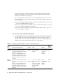
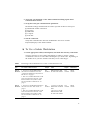
Netra™ ct Server Alarm Card
Installation Guide
Sun Microsystems, Inc.
901 San Antonio Road
Palo Alto, CA 94303
U.S.A. 650-960-1300
Part No. 806-3300-11
February 2001, Revision A
Send comments about this document to: [email protected]
Copyright 2001 Sun Microsystems, Inc., 901 San Antonio Road, Palo Alto, CA 94303-4900 U.S.A. All rights reserved.
This product or document is distributed under licenses restricting its use, copying, distribution, and decompilation. No part of this product or
document may be reproduced in any form by any means without prior written authorization of Sun and its licensors, if any. Third-party
software, including font technology, is copyrighted and licensed from Sun suppliers.
Parts of the product may be derived from Berkeley BSD systems, licensed from the University of California. UNIX is a registered trademark in
the U.S. and other countries, exclusively licensed through X/Open Company, Ltd.
Sun, Sun Microsystems, the Sun logo, AnswerBook2, docs.sun.com, Netra, and Solaris are trademarks, registered trademarks, or service marks
of Sun Microsystems, Inc. in the U.S. and other countries. All SPARC trademarks are used under license and are trademarks or registered
trademarks of SPARC International, Inc. in the U.S. and other countries. Products bearing SPARC trademarks are based upon an architecture
developed by Sun Microsystems, Inc.
The OPEN LOOK and Sun™ Graphical User Interface was developed by Sun Microsystems, Inc. for its users and licensees. Sun acknowledges
the pioneering efforts of Xerox in researching and developing the concept of visual or graphical user interfaces for the computer industry. Sun
holds a non-exclusive license from Xerox to the Xerox Graphical User Interface, which license also covers Sun’s licensees who implement OPEN
LOOK GUIs and otherwise comply with Sun’s written license agreements.
Federal Acquisitions: Commercial Software—Government Users Subject to Standard License Terms and Conditions.
DOCUMENTATION IS PROVIDED “AS IS” AND ALL EXPRESS OR IMPLIED CONDITIONS, REPRESENTATIONS AND WARRANTIES,
INCLUDING ANY IMPLIED WARRANTY OF MERCHANTABILITY, FITNESS FOR A PARTICULAR PURPOSE OR NON-INFRINGEMENT,
ARE DISCLAIMED, EXCEPT TO THE EXTENT THAT SUCH DISCLAIMERS ARE HELD TO BE LEGALLY INVALID.
Copyright 2001 Sun Microsystems, Inc., 901 San Antonio Road, Palo Alto, CA 94303-4900 Etats-Unis. Tous droits réservés.
Ce produit ou document est distribué avec des licences qui en restreignent l’utilisation, la copie, la distribution, et la décompilation. Aucune
partie de ce produit ou document ne peut être reproduite sous aucune forme, par quelque moyen que ce soit, sans l’autorisation préalable et
écrite de Sun et de ses bailleurs de licence, s’il y en a. Le logiciel détenu par des tiers, et qui comprend la technologie relative aux polices de
caractères, est protégé par un copyright et licencié par des fournisseurs de Sun.
Des parties de ce produit pourront être dérivées des systèmes Berkeley BSD licenciés par l’Université de Californie. UNIX est une marque
déposée aux Etats-Unis et dans d’autres pays et licenciée exclusivement par X/Open Company, Ltd.
Sun, Sun Microsystems, le logo Sun, AnswerBook2, docs.sun.com, Netra, et Solaris sont des marques de fabrique ou des marques déposées, ou
marques de service, de Sun Microsystems, Inc. aux Etats-Unis et dans d’autres pays. Toutes les marques SPARC sont utilisées sous licence et
sont des marques de fabrique ou des marques déposées de SPARC International, Inc. aux Etats-Unis et dans d’autres pays. Les produits portant
les marques SPARC sont basés sur une architecture développée par Sun Microsystems, Inc.
L’interface d’utilisation graphique OPEN LOOK et Sun™ a été développée par Sun Microsystems, Inc. pour ses utilisateurs et licenciés. Sun
reconnaît les efforts de pionniers de Xerox pour la recherche et le développement du concept des interfaces d’utilisation visuelle ou graphique
pour l’industrie de l’informatique. Sun détient une licence non exclusive de Xerox sur l’interface d’utilisation graphique Xerox, cette licence
couvrant également les licenciés de Sun qui mettent en place l’interface d’utilisation graphique OPEN LOOK et qui en outre se conforment aux
licences écrites de Sun.
LA DOCUMENTATION EST FOURNIE “EN L’ETAT” ET TOUTES AUTRES CONDITIONS, DECLARATIONS ET GARANTIES EXPRESSES
OU TACITES SONT FORMELLEMENT EXCLUES, DANS LA MESURE AUTORISEE PAR LA LOI APPLICABLE, Y COMPRIS NOTAMMENT
TOUTE GARANTIE IMPLICITE RELATIVE A LA QUALITE MARCHANDE, A L’APTITUDE A UNE UTILISATION PARTICULIERE OU A
L’ABSENCE DE CONTREFAÇON.
Please
Recycle
Contents
1.
Installing the Alarm Card
Installation Requirements
1
1
Connecting a Terminal Console to the Netra ct Server
Verifying the Alarm Card Software Installation
1
10
Verifying You Have the Correct Alarm Card for Your Netra ct Server
Verifying the Alarm Card I/O Slot Is Available
Attaching the Antistatic Wrist Strap
Installing the Alarm Card
11
15
16
Installing an Alarm Card in a Netra ct 800 Server
16
Installing an Alarm Card in a Netra ct 400 Server
23
Connecting the Cables
What’s Next
11
26
41
iii
iv
Netra ct Server Alarm Card Installation Guide • February 2001
Preface
The Netra ct Server Alarm Card Installation Guide describes how to install the optional
alarm card in the Netra™ ct servers. This guide has instructions for both the Netra
ct 800 server and the Netra ct 400 server.
The intended reader of this manual is an experienced system administrator who has
installed cards and other components in servers in telco environments. Knowledge
of the Solaris™ operating environment is a plus.
Before performing the procedures described in this book, you should have
completed the installation and setup of the Netra ct server, as described in the Netra
ct Server Installation Guide.
Safety and Compliance
All Netra ct servers are shipped with the Netra ct Server Safety and Compliance
Manual, which specifies the environmental and electrical safety requirements for the
product and contains compliance certification for various countries.
Using UNIX Commands
This document contains only limited information on basic UNIX® commands and
procedures such as shutting down the system, booting the system, and configuring
devices.
v
See one or more of the following for this information:
■
Solaris Handbook for Sun Peripherals (shipped in AnswerBook™ form, available in
printed form as an at-cost option.)
■
AnswerBook online documentation for the Solaris software environment
■
Other software documentation that you received with your system
Typographic Conventions
Typeface or
Symbol
Meaning
Examples
AaBbCc123
The names of commands, files,
and directories; on-screen
computer output
Edit your .login file.
Use ls -a to list all files.
% You have mail.
AaBbCc123
What you type, when
contrasted with on-screen
computer output
% su
Password:
AaBbCc123
Book titles, new words or terms,
words to be emphasized
Read Chapter 6 in the User’s Guide.
These are called class options.
You must be superuser to do this.
Command-line variable; replace
with a real name or value
To delete a file, type rm filename.
Shell Prompts
vi
Shell
Prompt
C shell
machine_name %
C shell superuser
machine_name #
Bourne shell and Korn shell
$
Bourne shell and Korn shell superuser
#
Netra ct Server Alarm Card Installation Guide • February 2001
Related Documentation
In addition to this Alarm Card Installation Guide, the alarm card option is
accompanied by the following manual:
Title
Part Number
Sun Remote System Control (RSC) User’s Guide for the
Netra ct Server Alarm Card
806-3301
The alarm card manuals are companion pieces to the standard Netra ct server
manuals:
Title
Part Number
Netra ct Server Start Here
806-5161
Netra ct Server Product Notes
806-3299
Netra ct Server Safety and Compliance Manual
806-3295
Netra ct Server Product Overview
806-3298
Netra ct Server Installation Guide
806-3294
Netra ct Server Service Manual
806-3296
Depending on the options you might have purchased for your machine, you might
have also received manuals for network interface cards.
As mentioned above, as a Netra ct server purchaser, you receive a suite of online
documentation for the Solaris operating environment.
Accessing Sun Documentation Online
Documentation and product information for the Netra product line is available at:
http://www.sun.com/products-n-solutions/hw/networking
vii
The docs.sun.comsm web site enables you to access Sun technical documentation
for the Solaris operating environment on the Web. You can browse the
docs.sun.com archive or search for a specific book title or subject at:
http://docs.sun.com
Ordering Sun Documentation
Fatbrain.com, an Internet professional bookstore, stocks select product
documentation from Sun Microsystems, Inc.
For a list of documents and how to order them, visit the Sun Documentation Center
on Fatbrain.com at:
http://www.fatbrain.com/documentation/sun
Sun Welcomes Your Comments
Sun is interested in improving its documentation and welcomes your comments and
suggestions. You can email your comments to Sun at:
[email protected]
Please include the part number (806-3300-11) of your document in the subject line of
your email.
viii
Netra ct Server Alarm Card Installation Guide • February 2001
Installing the Alarm Card
This chapter contains instructions for installing an alarm card in both the Netra ct
400 server and the Netra ct 800 server. It can be used in both the front-access and
rear-access models of the Netra ct servers. This chapter is organized as follows:
■
■
■
■
■
■
“Installation Requirements” on page 1
“Connecting a Terminal Console to the Netra ct Server” on page 1
“Attaching the Antistatic Wrist Strap” on page 15
“Installing the Alarm Card” on page 16
“Connecting the Cables” on page 26
“What’s Next” on page 41
Installation Requirements
You must verify that the following conditions are met before you can install the
alarm card and, if necessary, the alarm rear transition card, into your Netra ct 800
server or Netra ct 400 server:
■
■
■
■
“Connecting a Terminal Console to the Netra ct Server” on page 1
“Verifying the Alarm Card Software Installation” on page 10
“Verifying You Have the Correct Alarm Card for Your Netra ct Server” on page 11
“Verifying the Alarm Card I/O Slot Is Available” on page 11
Connecting a Terminal Console to the Netra ct
Server
You will have to log into your server and perform certain software commands in
order to install an alarm card successfully. You can log into the server either
remotely, where you would log into the Netra ct server as root through another
1
server on the network, or directly, where you would connect a terminal console
directly to your Netra ct server. A terminal console could be either an ASCII
terminal, a workstation, or PC laptop.
For a direct login, the connection you use varies depending on the Netra ct server
model you have, the type of terminal console you are using, and the card that you
are connecting to:
▼
■
If you are using an ASCII terminal to power on and off the Netra ct server, go to
“To Use an ASCII Terminal” on page 2.
■
If you are using a Solaris workstation to power on and off the Netra ct server, go
to “To Use a Solaris Workstation” on page 3.
■
If you are using a PC laptop to power on and off the Netra ct server, go to “To
Use a PC Laptop” on page 4.
To Use an ASCII Terminal
1. Get the appropriate cable(s) and adapter(s) and make the necessary connections.
You may need one or more cables and adapters in order to connect the ASCII
terminal to the server. The cables and adapters you need varies, depending on the
model server you have and the card that you are connecting to.
TABLE 1
Server
Type
Connecting an ASCII Terminal to a CPU or CPU Transition Card
Serial
Port on
Terminal
TTY A Port on Netra ct Server
Adapter
Cable
Adapter
Netra ct
800 server
• Front-access model: DB-9 male on
the CPU front transition card. See
“CPU Front Transition Card, Netra ct
800 Server” on page 7.
• Rear-access model: DB-9 male on
the CPU rear transition card. See
“CPU Rear Transition Card, Netra ct
800 Server and Netra ct 400 Server”
on page 9.
Not
needed.
DB-9 female-to-DB25 male straightthrough
DB-25
female-to-DB25 female
gender
changer
DB-25
male
Netra ct
400 server
• Front-access model: DIN-8 female
on the CPU card. See “CPU Card” on
page 5.
• Rear-access model: DB-9 male on
the CPU rear transition card. See
“CPU Rear Transition Card, Netra ct
800 Server and Netra ct 400 Server”
on page 9.
Not
needed.
• Front-access model:
DIN-8 male-to-DB-25
male
• Rear-access model:
DB-9 female-to-DB25 male straightthrough
DB-25
female-to-DB25 female
gender
changer
DB-25
male
2
Netra ct Server Alarm Card Installation Guide • February 2001
2. Access the “Set Up Menu” of the ASCII terminal and bring up the Serial
Communications section.
3. Set up the serial port communications parameters.
The default settings should match the values reported on the host serial port.
■
■
■
■
■
Hardwired modem connection
No parity
9600 baud
1 stop bit
8 bit data
4. Test the connection.
Verify that communication has been established to the server and the
keyboard/display of the ASCII terminal.
▼
To Use a Solaris Workstation
1. Get the appropriate cable(s) and adapter(s) and make the necessary connections.
You may need one or more cables and adapters in order to connect a Solaris
workstation to the server. The cables and adapters you need varies, depending on
the model server you have and the card that you are connecting to.
TABLE 2
Server
Type
Connecting a Solaris Workstation to a CPU or CPU Transition Card
TTY A Port on Netra ct Server
Adapter
Cable
Adapter
Serial Port on
Workstation
Netra ct
800 server
• Front-access model: DB-9 male on
the CPU front transition card. See
“CPU Front Transition Card, Netra ct
800 Server” on page 7.
• Rear-access model: DB-9 male on the
CPU rear transition card. See “CPU
Rear Transition Card, Netra ct 800
Server and Netra ct 400 Server” on
page 9.
Not
needed.
DB-9 female-to-DB25 male null modem
Not
needed
DB-25
female
Netra ct
400 server
• Front-access model: DIN-8 female on
the CPU card. See “CPU Card” on
page 5.
• Rear-access model: DB-9 male on the
CPU rear transition card. See “CPU
Rear Transition Card, Netra ct 800
Server and Netra ct 400 Server” on
page 9.
Not
needed.
• Front-access model:
DIN-8 male-to-DB-25
male
• Rear-access model:
DB-9 female-to-DB25 male null modem
Not
needed.
DB-25
female
3
2. Check the /etc/remote file for the appropriate line.
To connect to the TTY A or COM 1 port on the workstation, check for this line:
tip -9600 /dev/ttya
3. Type tip hardwire at the prompt.
You should see the word connected as the response.
To disconnect the tip window, type ~. (tilde period) at the prompt.
▼
To Use a PC Laptop
1. Get the appropriate cable(s) and adapter(s) and make the necessary connections.
You may need one or more cables and adapters in order to connect a PC laptop to
the server. The cables and adapters you need varies, depending on the model server
you have and the card that you are connecting to.
TABLE 3
Server
Type
Connecting a PC Laptop to a CPU or CPU Transition Card
Serial
Port on
PC
Laptop
TTY A Port on Netra ct Server
Adapter
Cable
Adapter
Netra
ct 800
server
• Front-access model: DB-9 male
on the CPU front transition
card. See “CPU Front Transition
Card, Netra ct 800 Server” on
page 7.
• Rear-access model: DB-9 male
on the CPU rear transition card.
See “CPU Rear Transition Card,
Netra ct 800 Server and Netra ct
400 Server” on page 9.
Not
needed.
DB-9 female-to-DB-9
female null modem
Not needed.
DB-9
male
Netra
ct 400
server
• Front-access model: DIN-8
female on the CPU card. See
“CPU Card” on page 5.
• Rear-access model: DB-9 male
on the CPU rear transition card.
See “CPU Rear Transition Card,
Netra ct 800 Server and Netra ct
400 Server” on page 9.
Not
needed.
• Front-access model:
DIN-8 male-to-DB25 male
• Rear-access model:
DB-9 female-to-DB-9
female null modem
• Front-access model:
DB-25 female-to-DB-9
female
• Rear-access model:
Adapter not needed.
DB-9
male
4
Netra ct Server Alarm Card Installation Guide • February 2001
2. Set the following connection parameters:
■
■
■
■
No parity
9600 baud
1 stop bit
8 bit data
Connectors on the CPU and CPU Transition Card
CPU Card
COM port
TTY A (DIN8)
Com
pact
ETH
ER
CO
STA
PC TM
I
NE
M
TUS
ALA
RE
RE
FIGURE 1
mic
RM
AD
Y
SET
AB
CP
T
OR
ros
1500
yste
T
ms
-360
Connectors on the CPU Card
5
This port is connected logically to serial port A, which is intended to be used as a
console port to connect to a terminal.
Caution – Serial port A is also connected through the rear CompactPCI connectors.
No mechanism is provided to disable simultaneous input from the front panel and
the rear CompactPCI connectors. Attempts to input data from both ports will place
the board in an unknown state.
G
DCD
H
NC
C
TXD
A
DTR
FIGURE 2
6
F
RTS
D
GND
E
RXD
B
CTS
CPU Card Front Panel TTYA Diagram
Netra ct Server Alarm Card Installation Guide • February 2001
CPU Front Transition Card, Netra ct 800 Server
Com
HD
D1
pact
ETH
ER
CO
STA
PC TM
I
NE
M
ALA
RE
mic
RM
AD
Y
SET
AB
FIGURE 3
TTY A
TUS
RE
CP
T
OR
ros
1500
yste
T
ms
-360
Connectors on the CPU Front Transition Card (Netra ct 800 Server)
7
The TTY A port on the CPU front transition card for the Netra ct 800 server is a DB9
male connector.
1
5
6
FIGURE 4
8
9
TTY A Connector
TABLE 4
TTY A Port Pinouts, CPU FTC for Netra ct 800 Server
Pin No.
Signal Name
1
DCD
2
RXD
3
TXD
4
DTR
5
GND
6
DSR
7
RTS
8
CTS
9
RI
Netra ct Server Alarm Card Installation Guide • February 2001
CPU Rear Transition Card, Netra ct 800 Server and Netra ct 400 Server
TTY A
FIGURE 5
Connectors on the CPU Rear Transition Card (Netra ct 800 Server)
TTY A
FIGURE 6
Connectors on the CPU Rear Transition Card (Netra ct 400 Server)
9
The TTY A port on the CPU rear transition card is a DB-9 male connector.
1
5
6
FIGURE 7
9
TTY A Connector
TABLE 5
TTY A Port Pinouts, CPU RTC
Pin No.
Signal Name
1
DCD
2
RXD
3
TXD
4
DTR
5
GND
6
DSR
7
RTS
8
CTS
9
RI
Verifying the Alarm Card Software Installation
The alarm card software is included on the Supplement for Solaris Operating
Environment for Sun Computer Systems CD that came with the Solaris operating
environment, so the alarm card software should have been installed when you
installed the Solaris operating environment on your system.
▼
To Verify the Alarm Card Software Package
Installation
Type:
# pkginfo SUNWctac
10
Netra ct Server Alarm Card Installation Guide • February 2001
You should see output similar to the following:
system
SUNWctac
Netra ct Alarm Card Firmware and Utilities
If you do not see the output given above, refer to the Netra ct Server Installation Guide
for instructions on installing the alarm card software before proceeding with these
instructions.
Verifying You Have the Correct Alarm Card for
Your Netra ct Server
The type of card(s) needed for your Netra ct server differ depending on the type and
model of your server. Refer to TABLE 6 to determine which card(s) you need for your
Netra ct server.
TABLE 6
Alarm Cards Needed for Netra ct Servers
Server Model
Front-Access Models
Rear-Access Models
Netra ct 800 server
Single-wide 6U alarm card
(x7161A)
Single-wide 6U alarm card
(X7161A) and single-wide 6U
alarm rear transition card
(X7176A)
Netra ct 400 server
Double-wide 3U alarm card
(X7160A)
Not supported
Verifying the Alarm Card I/O Slot Is Available
Before you can install an alarm card and, if necessary, an alarm rear transition card,
you must first verify that the alarm card I/O slot is not already occupied (note that
the alarm card is not supported on the rear-access model of the Netra ct 400 server):
■
■
■
“Netra ct 800 Server, Front-Access Model” on page 12
“Netra ct 800 Server, Rear-Access Model” on page 13
“Netra ct 400 Server, Front-Access Model” on page 14
11
Netra ct 800 Server, Front-Access Model
The front I/O slot 8 must be unoccupied before you can install an alarm card into a
front-access model of the Netra ct 800 server. FIGURE 8 shows where I/O slot 8 is
located on the front of the Netra ct 800 server; you can also find the I/O slot
numbers for a Netra ct 800 server on the sticker beneath the I/O slots. You must
install the alarm card in I/O slot 8 in the Netra ct 800 server; you cannot install the
alarm card in any other slot.
I/O slot 8
Netra ct 800 server
HD
D1
FIGURE 8
12
Alarm Card for the Netra ct 800 Server
Netra ct Server Alarm Card Installation Guide • February 2001
Netra ct 800 Server, Rear-Access Model
The front and the rear I/O slots 8 must be unoccupied before you can install an
alarm card into a front-access model of the Netra ct 800 server. FIGURE 8 shows
where I/O slot 8 is located on the front of the Netra ct 800 server, and FIGURE 9
shows where I/O slot 8 is located at the rear of the Netra ct 800 server; you can also
find the I/O slot numbers for a Netra ct 800 server on the sticker beneath the I/O
slots. You must install the alarm card in I/O slot 8 in the Netra ct 800 server; you
cannot install the alarm card in any other slot.
I/O slot 8
Netra ct 800 server
FIGURE 9
Alarm Rear Transition Card for the Netra ct 800 Server
13
Netra ct 400 Server, Front-Access Model
The lower half of front I/O slots 1 and 2 must be unoccupied before you can install
the double-wide 3U alarm card into a front-access model of the Netra ct 400 server.
FIGURE 10 shows where the front I/O slots 1 and 2 are located on the Netra ct 400
server; you can also find the I/O slot numbers for a Netra ct 400 server on the sticker
beneath the I/O slots. You must install the alarm card in I/O slots 1 and 2 in the
Netra ct 400 server; you cannot install the alarm card in any other slots.
I/O slots 1 and 2
Netra ct 400 server
FIGURE 10
14
HD
D0
Alarm Card for the Netra ct 400 Server
Netra ct Server Alarm Card Installation Guide • February 2001
Attaching the Antistatic Wrist Strap
Before you can install an alarm card or alarm rear transition card, you must attach
the antistatic wrist strap to the chassis.
1. Get the antistatic wrist strap and the electrostatic discharge mat from the ship kit.
2. Place an electrostatic discharge mat close to the system.
3. Unwrap the first two folds of the wrist strap and wrap the adhesive side firmly
against your wrist.
4. Peel the liner from the copper foil at the opposite end of the wrist strap and attach
the copper end of the strap to a bare metal area on the front of the Netra ct server
or the chassis.
Comp
act
ETHE
PC TM
I
RN
CO
STAT
ET
M
US
ALAR
RE
RE
HD
D1
Comp
M
AD
Y
HD
D0
act
ETHE
PC TM
I
RN
ET
SET
AB
OR
T
CO
M
HD
D0
STAT
US
micro
syste
ms
ALAR
RE
RE
M
AD
Y
SET
AB
OR
T
micro
syste
ms
FIGURE 11
Attaching the Antistatic Wrist Strap
15
Installing the Alarm Card
■
If you are installing an alarm card in a Netra ct 800 server, front-access or rearaccess model, go to “Installing an Alarm Card in a Netra ct 800 Server” on
page 16.
■
If you are installing an alarm card in a Netra ct 400 server, front-access model
only, go to “Installing an Alarm Card in a Netra ct 400 Server” on page 23.
Installing an Alarm Card in a Netra ct 800 Server
This section describes how to install an alarm card in a Netra ct 800 server. The
alarm card is a hot-swappable card, which means that you can install the card into a
Netra ct server while the server is running; you do not have to power-off the server
before installing the card.
▼
■
If you are installing an alarm card in the rear-access model of the Netra ct 800
server, you first install the alarm rear transition card, then you install the alarm
card. The alarm card will detect the presence of the alarm rear transition card and
will automatically switch access from the I/O connectors on the alarm card to the
I/O connectors on the alarm rear transition card. Follow the instructions in “To
Install the Rear Transition Card Into a Netra ct 800 Server” on page 16 first, and
then go to “To Install the Alarm Card Into a Netra ct 800 Server” on page 18.
■
If you are installing an alarm card in the front-access model of the Netra ct 800
server, you only need to install the single-wide 6U alarm card. Go to “To Install
the Alarm Card Into a Netra ct 800 Server” on page 18.
To Install the Rear Transition Card Into a Netra
ct 800 Server
This section describes how to install a rear transition card for the alarm card in the
rear-access model of the Netra ct server. Do not install a rear transition card if you
have a front-access model of the Netra ct server.
1. Go to the rear of the Netra ct server and attach the wrist strap to a bare metal area
on the system.
Refer to “Attaching the Antistatic Wrist Strap” on page 15 for more information.
2. Locate the slot where you will be installing the alarm rear transition card (alarm
RTC).
16
Netra ct Server Alarm Card Installation Guide • February 2001
Midplane
Front of
chassis
Rear of
chassis
Hard disk drives
Slot 1
CPU card
CPU RTC
Slot 1
Slot 2
Front I/O card
I/O RTC
Slot 2
Slot 3
Front I/O card
I/O RTC
Slot 3
Slot 4
Front I/O card
I/O RTC
Slot 4
Slot 5
Front I/O card
I/O RTC
Slot 5
Slot 6
Front I/O card
I/O RTC
Slot 6
Slot 7
Front I/O card
I/O RTC
Slot 7
Slot 8
Alarm card
Alarm RTC
Slot 8
FIGURE 12
Locating the Slot for the Rear Transition Card (RTC) for the Alarm Card (Top
View)
3. Remove the filler panel from the slot, if necessary.
The filler panel is secured to the slot using two screws, one at the top and one at the
bottom.
4. Get the alarm rear transition card from the ship kit.
5. Keeping the card vertical, slide the card into the slot in between the two guides
(FIGURE 13).
The teeth in the handle of the card must align with the square cutouts in the I/O
slot. When the card is completely seated in the card cage, the two ejection levers
should flip inward, and the teeth in the ejection levers should fit smoothly in the
rectangular cutouts in the bottom and top plates. FIGURE 13 shows how to insert an
I/O card into a slot; the same principal applies to an alarm rear transition card.
6. Lock the ejection levers on the card.
7. Using a No. 2 Phillips screwdriver, tighten the two captive screws inside the card’s
ejection levers, one on top and one on the bottom.
8. Go to “To Install the Alarm Card Into a Netra ct 800 Server” on page 18.
17
▼
To Install the Alarm Card Into a Netra ct 800
Server
Caution – When moving a number of cards to different slots in the system, move
the cards one at a time. If you move multiple cards in rapid succession, you might
panic or hang the system.
1. Attach the antistatic wrist strap, if you haven’t done so already.
Refer to “Attaching the Antistatic Wrist Strap” on page 15.
2. Remove the slot filler panel, if necessary.
The slot filler panel is secured to the card cage using two screws, one at the top of
the filler panel, the other at the bottom.
3. Get the alarm card from the ship kit.
4. Keeping the card vertical, slide it into the slot between the two guides.
The teeth in the handle of the card must align with the square cutouts in the I/O
slot. When the card is completely seated in the card cage, the two ejection levers
should flip inward, and the teeth in the ejection levers should fit smoothly in the
rectangular cutouts in the bottom and top plates. FIGURE 13 shows how to insert an
I/O card into a slot; the same principle applies to an alarm card.
18
Netra ct Server Alarm Card Installation Guide • February 2001
Comp
act
ETHE
PC TM
I
RN
CO
STAT
ET
M
US
ALAR
RE
RE
HD
D1
M
AD
Y
HD
D0
SET
AB
OR
T
HD
D0
micros
ystem
s
FIGURE 13
Aligning the Card with the Card Cage Cutouts
5. Lock the ejection levers.
6. Locate the LEDs on the system status panel for the alarm card that you just
installed to determine if the card has been activated.
FIGURE 14 shows the locations of the I/O card LEDs on the Netra ct 800 server.
19
Alarm card LEDs
FIGURE 14
Locating the Alarm Card LEDs on the System Status Panel (Netra ct 800
Server)
The amber Okay to Remove LED (
the alarm card has been activated.
) on the system status panel indicates whether
■
If the amber Okay to Remove LED (
) on the system status panel is OFF, the
I/O slot that holds the alarm card has been set to full hot swap and the card has
been activated. Go to Step 11 on page 22.
■
If the amber Okay to Remove LED (
) on the system status panel is ON, the
I/O slot that holds the alarm card has been set to basic hot swap. You must use
the cfgadm utility to activate the alarm card. Go to Step 7.
7. Log in to the Netra ct server.
Refer to “Connecting a Terminal Console to the Netra ct Server” on page 1, then
return here.
20
Netra ct Server Alarm Card Installation Guide • February 2001
8. Identify the attachment-point ID that corresponds to I/O slot 8, which holds the
alarm card.
As root, enter:
# cfgadm pci
For a Netra ct 800 server, you should get output similar to the following:
Ap_Id
pci_pci0:cpci_slot2
pci_pci0:cpci_slot3
pci_pci0:cpci_slot4
pci_pci0:cpci_slot5
pci_pci0:cpci_slot6
pci_pci0:cpci_slot7
pci_pci0:cpci_slot8
Type
unknown
stpcipci/fhs
unknown
unknown
unknown
unknown
unknown
Receptacle
empty
connected
disconnected
empty
empty
empty
disconnected
Occupant
unconfigured
configured
unconfigured
unconfigured
unconfigured
unconfigured
unconfigured
Condition
unknown
ok
unknown
unknown
unknown
unknown
unknown
The attachment-point ID is shown in the first column of the readout; for example,
the attachment-point ID for I/O slot 8 in a Netra ct 800 server would be
pci_pci0:cpci_slot8. Note that the information for the card installed in I/O slot
8 in the example output shows it as unknown (Type), disconnected (Receptacle),
unconfigured (Occupant), and unknown (Condition). This confirms that the I/O slot
has been set to basic hot swap and that the card in the I/O slot has not yet been
activated.
9. Connect the alarm card with the cfgadm dynamic reconfiguration software:
# cfgadm -c connect ap_id
where ap_id is the attachment-point ID. For example, to connect the alarm card in
slot 8, as root, type:
# cfgadm -c connect pci_pci0:cpci_slot8
The amber Okay to Remove LED (
) on the system status panel for the I/O slot
should go OFF, indicating that the card has been connected.
10. Activate the alarm card with the cfgadm dynamic reconfiguration software:
# cfgadm -c configure ap_id
21
where ap_id is the attachment-point ID. For example, to activate the alarm card in
slot 8, as root, type:
# cfgadm -c configure pci_pci0:cpci_slot8
If you were to enter the cfgadm pci command again at this point, you would see
the fields changed for the card in I/O slot 8:
Ap_Id
pci_pci0:cpci_slot2
pci_pci0:cpci_slot3
pci_pci0:cpci_slot4
pci_pci0:cpci_slot5
pci_pci0:cpci_slot6
pci_pci0:cpci_slot7
pci_pci0:cpci_slot8
Type
unknown
stpcipci/fhs
unknown
unknown
unknown
unknown
stpcipci/fhs
Receptacle
empty
connected
empty
empty
empty
empty
connected
Occupant
unconfigured
configured
unconfigured
unconfigured
unconfigured
unconfigured
configured
Condition
unknown
ok
unknown
unknown
unknown
unknown
ok
11. Using a No. 2 Phillips screwdriver, tighten the two captive screws inside the card’s
ejection levers, one on top and one on the bottom.
12. Attach the cables to the alarm card and, if necessary, to the alarm rear transition
card.
Go to “Connecting the Cables” on page 26 to connect the cables to the alarm card
you just installed.
22
Netra ct Server Alarm Card Installation Guide • February 2001
Installing an Alarm Card in a Netra ct 400 Server
Note – The alarm card is not an option for the rear-access model of the Netra ct 400
server.
This section describes how to install an alarm card in a Netra ct 400 server.
▼
To Install an Alarm Card in a Netra ct 400 Server
1. Go to the front of the Netra ct server and attach the wrist strap to a bare metal area
on the system.
Refer to “Attaching the Antistatic Wrist Strap” on page 15 for more information.
2. Remove the slot filler panel, if necessary.
The slot filler panel is secured to the card cage using thee screws, two at the top of
the filler panel, one at the bottom. Store the slot filler panel in a safe place; you may
have to use it again if you have to remove an alarm card for an extended period of
time.
3. Get the alarm card from the ship kit.
4. Keeping the card vertical, slide it into slot 1 between the two guides.
5. Lock the ejection lever.
6. Locate the LEDs on the system status panel for the alarm card that you just
installed to determine if the card has been activated.
FIGURE 15 shows the locations of the alarm card LEDs on the Netra ct 400 server.
23
Alarm card LEDs
FIGURE 15
Locating the Alarm Card LEDs on the System Status Panel (Netra ct 400
Server)
The amber Okay to Remove LED (
the alarm card has been activated.
) on the system status panel indicates whether
■
If the amber Okay to Remove LED (
) on the system status panel is OFF, the
I/O slot that controls the alarm card has been set to full hot swap and the card has
been activated. Go to Step 11 on page 26.
■
If the amber Okay to Remove LED (
) on the system status panel is ON, the
I/O slot that controls the alarm card has been set to basic hot swap. You must use
the cfgadm utility to activate the alarm card. Go to Step 7.
7. Log in to the Netra ct server.
Refer to “Connecting a Terminal Console to the Netra ct Server” on page 1, and then
return here.
8. Identify the attachment-point ID that corresponds to the I/O slot 1, which controls
the alarm card.
As root, enter:
# cfgadm pci
24
Netra ct Server Alarm Card Installation Guide • February 2001
For a Netra ct 400 server, you should get output similar to the following:
Ap_Id
pci_pci0:cpci_slot1
pci_pci0:cpci_slot2
pci_pci0:cpci_slot4
pci_pci0:cpci_slot5
Type
unknown
unknown
stpcipci/fhs
unknown
Receptacle
disconnected
disconnected
connected
empty
Occupant
unconfigured
unconfigured
configured
unconfigured
Condition
unknown
unknown
ok
unknown
The attachment-point ID is shown in the first column of the readout; for example,
the attachment-point ID for I/O slot 1 in a Netra ct 400 server would be
pci_pci0:cpci_slot1. Note that the information for the card installed in I/O slot
1 in the example output shows it as unknown (Type), disconnected (Receptacle),
unconfigured (Occupant), and unknown (Condition). This confirms that the I/O slot
has been set to basic hot swap and that the card in the I/O slot has not yet been
activated.
9. Connect the alarm card with the cfgadm dynamic reconfiguration software:
# cfgadm -c connect ap_id
where ap_id is the attachment-point ID. For example, to connect the alarm card in
slot 1, as root, type:
# cfgadm -c connect pci_pci0:cpci_slot1
The amber Okay to Remove LED (
) on the system status panel for the I/O slot
should go OFF, indicating that the card has been connected.
10. Activate the alarm card with the cfgadm dynamic reconfiguration software:
# cfgadm -c configure ap_id
25
where ap_id is the attachment-point ID. For example, to activate the alarm card in
slot 1, as root, type:
# cfgadm -c configure pci_pci0:cpci_slot1
If you were to enter the cfgadm pci command again at this point, you would see
the fields changed for the card in I/O slot 1:
Ap_Id
pci_pci0:cpci_slot1
pci_pci0:cpci_slot2
pci_pci0:cpci_slot4
pci_pci0:cpci_slot5
Type
stpcipci/fhs
unknown
stpcipci/fhs
unknown
Receptacle
connected
disconnected
connected
empty
Occupant
configured
unconfigured
configured
unconfigured
Condition
ok
unknown
ok
unknown
11. Using a No. 2 Phillips screwdriver, tighten the captive screw inside the card’s
ejection lever on the bottom left side.
12. Tighten the three remaining captive screws, two on the top and one on the bottom.
13. Attach the cables to the alarm card.
Go to “Connecting the Cables” on page 26 to connect the cables to the alarm card
you just installed.
Connecting the Cables
Note – The maximum voltage that can be applied to an alarm card is 60vdc, as
specified in UL1950 and IEC 60950. The maximum current is 500mA.
Following are the instructions for connecting the cables to the alarm card(s):
26
■
“To Connect Cables to the Alarm Rear Transition Card for the Netra ct 800
Server” on page 27
■
“To Connect Cables to the Alarm Card for the Netra ct 800 Server” on page 32
■
“To Connect Cables to the Alarm Card for the Netra ct 400 Server” on page 37
Netra ct Server Alarm Card Installation Guide • February 2001
▼
To Connect Cables to the Alarm Rear Transition
Card for the Netra ct 800 Server
FIGURE 16 shows the connectors on the alarm rear transition card for the Netra ct 800
server.
Ethernet
COM 2
COM 1
Alarm
FIGURE 16
Connectors on the Alarm Rear Transition Card
■
If you already have the cables assembled for the alarm rear transition card, plug
the cables into the ports.
■
If you need to assemble the cables for the alarm rear transition card, go to
“Connector Pinouts for the Alarm Rear Transition Card” on page 27 to assemble
the cables and plug them into the appropriate ports.
Connector Pinouts for the Alarm Rear Transition Card
The following sections give the pinouts for the connectors on the alarm rear
transition card:
■
■
■
■
“Ethernet Port” on page 28
“COM 2” on page 29
“COM 1” on page 30
“Alarm Port” on page 31
27
Ethernet Port
The Ethernet port on the alarm RTC for the Netra ct 800 server is an RJ-45 connector
for 10BASE-T.
1
FIGURE 17
28
8
RJ45 Ethernet Connector Diagram
TABLE 7
Ethernet Connector Pinout, Alarm RTC for the Netra ct 800 Server
Pin No.
Description
1
TXD+
2
TXD-
3
RXD+
4
Not used
5
Not used
6
RXD-
7
Not used
8
Not used
Netra ct Server Alarm Card Installation Guide • February 2001
COM 2
The COM 2 port on the alarm RTC for the Netra ct 800 server is a DB-9 male
connector.
1
5
6
FIGURE 18
9
COM 2 Connector
TABLE 8
COM 2 Connector Pinouts, Alarm RTC for the Netra ct 800 Server
Pin No.
Description
1
DCD
2
RXD
3
TXD
4
DTR
5
Isolated GND 2
6
DSR
7
RTS
8
CTS
9
NC
29
COM 1
The COM 1 port on the alarm RTC for the Netra ct 800 server is a DB-9 male
connector.
1
5
6
FIGURE 19
30
9
COM 1 Connector
TABLE 9
COM 1 Connector Pinouts, Alarm RTC for the Netra ct 800 Server
Pin No.
Description
1
NC
2
RXD
3
TXD
4
NC
5
Isolated GND 1
6
NC
7
RTS
8
CTS
9
NC
Netra ct Server Alarm Card Installation Guide • February 2001
Alarm Port
I/O connections are available through the male DB-15 alarm port.
8
1
9
15
TABLE 10
Alarm Port Pinouts, Alarm RTC for the Netra ct 800 Server
Pin No.
Signal
1
RESET0 +
2
RESET0 -
3
RESET1 +
4
RESET1 -
5
ALARM0_NO
6
ALARM0_NC
7
ALARM0_COM
8
ALARM1_NO
9
ALARM1_NC
10
ALARM1_COM
11
ALARM2_NO
12
ALARM2_NC
13
ALARM2_COM
14
ALARM3_NO
15
ALARM3_COM
31
▼
To Connect Cables to the Alarm Card for the
Netra ct 800 Server
Note – If you have a rear-access model server, do not connect any cables to the
alarm card; all cables should be connected to the alarm rear transition card for a
rear-access model server. Go to “To Connect Cables to the Alarm Rear Transition
Card for the Netra ct 800 Server” on page 27 for those instructions.
FIGURE 20 shows the connectors on the alarm card for the Netra ct 800 server.
HD
D1
PCMCIA slot (reserved)
Alarm (DB-15)
Ethernet
COM 1
COM 2
FIGURE 20
32
Plugging in Cables in Alarm Card in Netra ct 800 Server
Netra ct Server Alarm Card Installation Guide • February 2001
Connector Pinouts for the Alarm Card
The following sections give the pinouts for the connectors on the alarm card for the
Netra ct 800 server:
■
■
■
■
“Alarm Port” on page 33
“Ethernet Port” on page 34
“COM 1” on page 35
“COM 2” on page 36
Alarm Port
I/O connections are available through the male DB-15 alarm port.
8
1
9
FIGURE 21
TABLE 11
15
Alarm Port
Alarm Port Pinouts, Alarm Card for the Netra ct 800 Server
Pin No.
Signal
Pin No.
Signal
Pin No.
Signal
1
RESET0 +
6
ALARM0_NC
11
ALARM2_NO
2
RESET0 -
7
ALARM0_COM
12
ALARM2_NC
3
RESET1 +
8
ALARM1_NO
13
ALARM2_COM
4
RESET1 -
9
ALARM1_NC
14
ALARM3_NO
5
ALARM0_NO
10
ALARM1_COM
15
ALARM3_COM
33
Ethernet Port
The Ethernet port on the alarm card for the Netra ct 800 server is an RJ-45 connector
for 10BASE-T.
1
FIGURE 22
34
8
RJ-45 Ethernet Connector Diagram
TABLE 12
Ethernet Connector Pinouts, Alarm Card for the Netra ct 800 Server
Pin No.
Description
Pin No.
Description
1
TXD+
5
Not used
2
TXD- \
6
RXD-
3
RXD+
7
Not used
4
Not used
8
Not used
Netra ct Server Alarm Card Installation Guide • February 2001
COM 1
The COM 1 port on the alarm card for the Netra ct 800 server is a DB-9 male
connector.
1
5
6
FIGURE 23
9
COM 1 Connector
TABLE 13
COM 1 Connector Pinouts, Alarm Card for the Netra ct 800 Server
Pin No.
Description
1
NC
2
RXD
3
TXD
4
NC
5
Isolated GND 1
6
NC
7
RTS
8
CTS
9
NC
35
COM 2
The COM 2 port on the alarm card for the Netra ct 800 server is a DB-9 male
connector.
1
5
6
FIGURE 24
36
9
COM 2 Connector
TABLE 14
COM 2 Connector Pinouts, Alarm Card for the Netra ct 800 Server
Pin No.
Description
1
DCD
2
RXD
3
TXD
4
DTR
5
Isolated GND 2
6
DSR
7
RTS
8
CTS
9
NC
Netra ct Server Alarm Card Installation Guide • February 2001
▼
To Connect Cables to the Alarm Card for the
Netra ct 400 Server
FIGURE 25 shows the connectors on the alarm card for the Netra ct 400 server.
HD
D0
COM 2
COM 1
PCMCIA slot (reserved)
Alarm (DB-15)
Ethernet
FIGURE 25
Connectors on the Alarm Card (Netra ct 400 Server)
Connector Pinouts for the Alarm Card
The following sections give the pinouts for the connectors on the alarm card for the
Netra ct 400 server:
■
■
■
■
“COM 2” on page 38
“COM 1” on page 39
“Alarm Port” on page 40
“Ethernet Port” on page 41
37
COM 2
The COM 2 port on the alarm card for the Netra ct 400 server is an RJ-45 connector.
1
FIGURE 26
38
8
RJ-45 Ethernet Connector Diagram
TABLE 15
COM 2 Connector Pinouts, Alarm Card for the Netra ct 400 Server
Pin No.
Description
1
RTS
2
DTR
3
TXD
4
Isolated GND 2
5
Isolated GND 2
6
RXD
7
DSR
8
CTS
Netra ct Server Alarm Card Installation Guide • February 2001
COM 1
The COM 1 port on the alarm card for the Netra ct 400 server is an RJ-45 connector.
1
FIGURE 27
8
RJ-45 Ethernet Connector Diagram
TABLE 16
COM 1 Connector Pinouts, Alarm Card for the Netra ct 400 Server
Pin No.
Description
1
RTS
2
NC
3
TXD
4
Isolated GND 1
5
Isolated GND 1
6
RXD
7
NC
8
CTS
39
Alarm Port
I/O connections are available through the male DB-15 alarm port.
8
1
9
FIGURE 28
40
15
Alarm Port
TABLE 17
Alarm Port Pinouts, Alarm Card for the Netra ct 400 Server
Pin No.
Signal
1
RESET0 +
2
RESET0 -
3
RESET1 +
4
RESET1 -
5
ALARM0_NO
6
ALARM0_NC
7
ALARM0_COM
8
ALARM1_NO
9
ALARM1_NC
10
ALARM1_COM
11
ALARM2_NO
12
ALARM2_NC
13
ALARM2_COM
14
ALARM3_NO
15
ALARM3_COM
Netra ct Server Alarm Card Installation Guide • February 2001
Ethernet Port
The Ethernet port on the alarm card for the Netra ct 400 server is an RJ-45 connector
for 10BASE-T.
1
FIGURE 29
8
RJ-45 Ethernet Connector Diagram
TABLE 18
Ethernet Connector Pinouts, Alarm Card for Netra ct 400 Server
Pin No.
Description
1
TXD+
2
TXD-
3
RXD+
4
Not used
5
Not used
6
RXD-
7
Not used
8
Not used
What’s Next
The alarm card(s) are now installed and functioning normally. Go to the Remote
System Control (RSC) User’s Guide For the Netra ct Server Alarm Card to configure the
software for the alarm card (for example, to redirect the console to RSC).
41
If you want to remove the alarm card from the Netra ct server sometime in the
future, refer to the Netra ct Server Service Manual for those instructions.
42
Netra ct Server Alarm Card Installation Guide • February 2001