1
DRAFT—12/16/96
D:\DOCS\PPG\COVER.FMD
Percon Program Generator
Version 3.5
User Manual
1720 Willow Creek Circle
Suite 530
Eugene, OR 97402-9171
541-344-1189
FAX 541-344-1399
00-655-01
1/96
DRAFT—12/16/96
D:\DOCS\PPG\COPYRITE.FMD
© 1994
Percon, Inc.
1720 Willow Creek Circle
Suite 530
Eugene, OR 97402-9171
(503) 344-1189
(503) 344-1399 FAX
All rights reserved. No part of this work may be reproduced, transmitted, or stored in any
form or by any means without prior written consent, except by a reviewer, who may
quote brief passages in a review, or as provided for in the Copyright Act of 1976.
Percon® is a registered trademark of Percon Acquisition, Inc. Percon Program
Generator™, PPG™, PocketReader™, and PT 2000™ are trademarks of Percon
Acquisition, Inc.
Microsoft® and MS-DOS® are registered trademarks of Microsoft Corporation.
Windows™ is a trademark of Microsoft Corporation.
IBM®, IBM PC®, and PC-DOS® are registered trademarks of International Business
Machines Corporation.
All other product names are trademarks or registered trademarks of their manufacturers.
Many of the designations used by manufacturers and sellers to distinguish their products
are claimed as trademarks. Where these designations appear here and the authors
were aware of a trademark claim, the designations have been printed with a trademark
(™) symbol.
SOFTWARE LICENSE:
Percon grants the purchaser the right to use one copy of the Percon Program Generator
(PPG) software on one computer. The purchaser is hereby licensed to read the program
from its medium into the memory of the computer for the purpose of executing the
program or to copy the program for the purpose of archival backup or convenient
access, provided such copies are made solely in support of the purchaser's operation of
the program on a single computer.
COPYRIGHT:
Percon Program Generator (PPG) is owned by Percon and is protected by United States
copyright laws and international treaty provisions. Therefore, you must treat PPG like
any other copyrighted material (e.g., a book), except that you may either (a) make one
copy of PPG solely for backup or archival purposes, or (b) transfer PPG to a single hard
disk, provided you keep the original solely for backup or archival purposes. Copying
(except as mentioned above), duplicating, selling, or otherwise distributing this product
is a violation of Federal Copyright Law.
The information contained in this document is subject to change without notice.
DRAFT—12/16/96
D:\DOCS\PPG\PPG.TOC
Contents
*CONCONTENTS*CONTENTS*CONTENTS*CONTENTS*CONTENTS*CONTENTS*CONTENTS*CONTEN
Introduction . . . . . . . . . . . . . . . . . . . . . . . . . . . . . . . . . . . . . . . . . . . . . . . . . . . . . . .
Equipment Requirements . . . . . . . . . . . . . . . . . . . . . . . . . . . . . . . . . . . . . . . . . . . . . .
Before You Start . . . . . . . . . . . . . . . . . . . . . . . . . . . . . . . . . . . . . . . . . . . . . . . . . . . . .
How to Use This Manual . . . . . . . . . . . . . . . . . . . . . . . . . . . . . . . . . . . . . . . . . . . . . .
Typographic Conventions . . . . . . . . . . . . . . . . . . . . . . . . . . . . . . . . . . . . . . . . . . .
Technical Support . . . . . . . . . . . . . . . . . . . . . . . . . . . . . . . . . . . . . . . . . . . . . . . . . . .
1
2
2
2
3
4
CHAPTER 1: Getting Started . . . . . . . . . . . . . . . . . . . . . . . . . . . . . . . . . . . . . . . . . . . . . . . . . . . . .
Installing PPG . . . . . . . . . . . . . . . . . . . . . . . . . . . . . . . . . . . . . . . . . . . . . . . . . . . . . .
Loading and Exiting PPG . . . . . . . . . . . . . . . . . . . . . . . . . . . . . . . . . . . . . . . . . . . . . .
An Overview . . . . . . . . . . . . . . . . . . . . . . . . . . . . . . . . . . . . . . . . . . . . . . . . . . . . . . . .
Sample Program Files . . . . . . . . . . . . . . . . . . . . . . . . . . . . . . . . . . . . . . . . . . . . . . . .
5
5
6
7
8
CHAPTER 2: Tutorial . . . . . . . . . . . . . . . . . . . . . . . . . . . . . . . . . . . . . . . . . . . . . . . . . . . . . . . . . . . 9
Studying a Sample Program . . . . . . . . . . . . . . . . . . . . . . . . . . . . . . . . . . . . . . . . . . 10
Programming Your Portable . . . . . . . . . . . . . . . . . . . . . . . . . . . . . . . . . . . . . . . . . . . 15
Box: If You Have Problems . . . . . . . . . . . . . . . . . . . . . . . . . . . . . . . . . . . . . . . . . 16
Uploading Bar Code Data . . . . . . . . . . . . . . . . . . . . . . . . . . . . . . . . . . . . . . . . . . . . 16
Building Your Own Portable Program . . . . . . . . . . . . . . . . . . . . . . . . . . . . . . . . . . . . 18
Creating Frames and Links. . . . . . . . . . . . . . . . . . . . . . . . . . . . . . . . . . . . . . . . . 18
Creating the Main Menu Nodes . . . . . . . . . . . . . . . . . . . . . . . . . . . . . . . . . . . . . 20
Saving Your Program . . . . . . . . . . . . . . . . . . . . . . . . . . . . . . . . . . . . . . . . . . . . . 23
Creating and Setting Up the Collect Data Nodes . . . . . . . . . . . . . . . . . . . . . . . . 24
The Display : Enter Item Node . . . . . . . . . . . . . . . . . . . . . . . . . . . . . . . . . . 26
The Input : Item Node . . . . . . . . . . . . . . . . . . . . . . . . . . . . . . . . . . . . . . . . . 26
The Verify : Input Node . . . . . . . . . . . . . . . . . . . . . . . . . . . . . . . . . . . . . . . . 29
The Output : Error Beep Node . . . . . . . . . . . . . . . . . . . . . . . . . . . . . . . . . . 30
The Display : Error Text Node . . . . . . . . . . . . . . . . . . . . . . . . . . . . . . . . . . . 30
The Copy : To File Node . . . . . . . . . . . . . . . . . . . . . . . . . . . . . . . . . . . . . . . 31
iii
DRAFT—12/16/96
D:\DOCS\PPG\PPG.TOC
Contents
Creating and Setting Up the Upload Data Nodes . . . . . . . . . . . . . . . . . . . . . . . .
The Menu : Confirmation Node . . . . . . . . . . . . . . . . . . . . . . . . . . . . . . . . . .
The Output : to PC Node . . . . . . . . . . . . . . . . . . . . . . . . . . . . . . . . . . . . . . .
The Output : Error Beep Node . . . . . . . . . . . . . . . . . . . . . . . . . . . . . . . . . .
The Menu : Error Text Node . . . . . . . . . . . . . . . . . . . . . . . . . . . . . . . . . . . .
The Display : Successful Node . . . . . . . . . . . . . . . . . . . . . . . . . . . . . . . . . .
The Input : Timeout Display Node . . . . . . . . . . . . . . . . . . . . . . . . . . . . . . . .
The Modify : Erase File Node . . . . . . . . . . . . . . . . . . . . . . . . . . . . . . . . . . .
Emulating the Program . . . . . . . . . . . . . . . . . . . . . . . . . . . . . . . . . . . . . . . . . . . . . . .
Loading and Using the Program . . . . . . . . . . . . . . . . . . . . . . . . . . . . . . . . . . . . . . .
Box: If You Have Problems . . . . . . . . . . . . . . . . . . . . . . . . . . . . . . . . . . . . . . . . .
Uploading Data from the Portable . . . . . . . . . . . . . . . . . . . . . . . . . . . . . . . . . . . . . .
Creating and Using Templates . . . . . . . . . . . . . . . . . . . . . . . . . . . . . . . . . . . . . . . . .
Creating the New Nodes. . . . . . . . . . . . . . . . . . . . . . . . . . . . . . . . . . . . . . . . . . .
Creating the Fields . . . . . . . . . . . . . . . . . . . . . . . . . . . . . . . . . . . . . . . . . . . . . . .
32
33
34
34
35
35
36
36
37
40
41
42
43
44
46
CHAPTER 3: User’s Guide . . . . . . . . . . . . . . . . . . . . . . . . . . . . . . . . . . . . . . . . . . . . . . . . . . . . . .
Using Online Help . . . . . . . . . . . . . . . . . . . . . . . . . . . . . . . . . . . . . . . . . . . . . . . . . .
Using the Mouse . . . . . . . . . . . . . . . . . . . . . . . . . . . . . . . . . . . . . . . . . . . . . . . . . . .
Generating a Portable Program . . . . . . . . . . . . . . . . . . . . . . . . . . . . . . . . . . . . . . . .
Flow Chart Levels . . . . . . . . . . . . . . . . . . . . . . . . . . . . . . . . . . . . . . . . . . . . . . . .
Testing Your Program . . . . . . . . . . . . . . . . . . . . . . . . . . . . . . . . . . . . . . . . . . . . .
Creating Frames . . . . . . . . . . . . . . . . . . . . . . . . . . . . . . . . . . . . . . . . . . . . . . . . . . . .
Creating Subroutines . . . . . . . . . . . . . . . . . . . . . . . . . . . . . . . . . . . . . . . . . . . . . . . .
Creating and Using Links . . . . . . . . . . . . . . . . . . . . . . . . . . . . . . . . . . . . . . . . . . . . .
Creating Links. . . . . . . . . . . . . . . . . . . . . . . . . . . . . . . . . . . . . . . . . . . . . . . . . . .
Adjusting Links . . . . . . . . . . . . . . . . . . . . . . . . . . . . . . . . . . . . . . . . . . . . . . . . . .
Deleting Links . . . . . . . . . . . . . . . . . . . . . . . . . . . . . . . . . . . . . . . . . . . . . . . . . . .
Creating and Using Nodes . . . . . . . . . . . . . . . . . . . . . . . . . . . . . . . . . . . . . . . . . . . .
Call Nodes . . . . . . . . . . . . . . . . . . . . . . . . . . . . . . . . . . . . . . . . . . . . . . . . . . . . .
Copy Nodes . . . . . . . . . . . . . . . . . . . . . . . . . . . . . . . . . . . . . . . . . . . . . . . . . . . .
Display Nodes. . . . . . . . . . . . . . . . . . . . . . . . . . . . . . . . . . . . . . . . . . . . . . . . . . .
Input Nodes . . . . . . . . . . . . . . . . . . . . . . . . . . . . . . . . . . . . . . . . . . . . . . . . . . . .
Box: Echoing Input . . . . . . . . . . . . . . . . . . . . . . . . . . . . . . . . . . . . . . . . . . . .
Math Nodes . . . . . . . . . . . . . . . . . . . . . . . . . . . . . . . . . . . . . . . . . . . . . . . . . . . .
Menu Nodes . . . . . . . . . . . . . . . . . . . . . . . . . . . . . . . . . . . . . . . . . . . . . . . . . . . .
Modify Nodes . . . . . . . . . . . . . . . . . . . . . . . . . . . . . . . . . . . . . . . . . . . . . . . . . . .
Output Nodes . . . . . . . . . . . . . . . . . . . . . . . . . . . . . . . . . . . . . . . . . . . . . . . . . . .
Box: Outputting Commands to the System . . . . . . . . . . . . . . . . . . . . . . . . .
Verify Nodes . . . . . . . . . . . . . . . . . . . . . . . . . . . . . . . . . . . . . . . . . . . . . . . . . . . .
Box: Specifying a Range to Match . . . . . . . . . . . . . . . . . . . . . . . . . . . . . . . .
Controlling Data Flow . . . . . . . . . . . . . . . . . . . . . . . . . . . . . . . . . . . . . . . . . . . . . . . .
Registers. . . . . . . . . . . . . . . . . . . . . . . . . . . . . . . . . . . . . . . . . . . . . . . . . . . . . . .
Using a Register as a Source . . . . . . . . . . . . . . . . . . . . . . . . . . . . . . . . . . .
Using a Register as a Destination . . . . . . . . . . . . . . . . . . . . . . . . . . . . . . . .
Specifying a Register Field . . . . . . . . . . . . . . . . . . . . . . . . . . . . . . . . . . . . .
49
50
51
52
52
53
53
54
56
56
57
57
57
58
59
60
60
62
63
64
65
67
68
69
70
71
72
72
72
73
iv Percon Program Generator User Manual
DRAFT—12/16/96
D:\DOCS\PPG\PPG.TOC
Contents
Files . . . . . . . . . . . . . . . . . . . . . . . . . . . . . . . . . . . . . . . . . . . . . . . . . . . . . . . . . .
Using a File as a Source . . . . . . . . . . . . . . . . . . . . . . . . . . . . . . . . . . . . . . .
Using a File as a Destination . . . . . . . . . . . . . . . . . . . . . . . . . . . . . . . . . . .
Creating a Template . . . . . . . . . . . . . . . . . . . . . . . . . . . . . . . . . . . . . . . . . . . . . .
Modifying a Pick List . . . . . . . . . . . . . . . . . . . . . . . . . . . . . . . . . . . . . . . . . . . . . .
Breaking Down Data in a Register . . . . . . . . . . . . . . . . . . . . . . . . . . . . . . . . . . .
Editing a Flow Chart . . . . . . . . . . . . . . . . . . . . . . . . . . . . . . . . . . . . . . . . . . . . . . . . .
Cutting, Copying, and Pasting . . . . . . . . . . . . . . . . . . . . . . . . . . . . . . . . . . . . . .
Deleting Nodes and Frames . . . . . . . . . . . . . . . . . . . . . . . . . . . . . . . . . . . . . . . .
Renaming Nodes and Frames . . . . . . . . . . . . . . . . . . . . . . . . . . . . . . . . . . . . . .
General Options . . . . . . . . . . . . . . . . . . . . . . . . . . . . . . . . . . . . . . . . . . . . . . . . . . . .
Switching Display Size . . . . . . . . . . . . . . . . . . . . . . . . . . . . . . . . . . . . . . . . . . . .
Changing Fonts . . . . . . . . . . . . . . . . . . . . . . . . . . . . . . . . . . . . . . . . . . . . . . . . .
Adjusting the Grid and Box Size . . . . . . . . . . . . . . . . . . . . . . . . . . . . . . . . . . . . .
Specifying Bar Code Type . . . . . . . . . . . . . . . . . . . . . . . . . . . . . . . . . . . . . . . . .
Setting a Starting Place . . . . . . . . . . . . . . . . . . . . . . . . . . . . . . . . . . . . . . . . . . .
Working with Program Source Files . . . . . . . . . . . . . . . . . . . . . . . . . . . . . . . . . . . . .
Opening a File . . . . . . . . . . . . . . . . . . . . . . . . . . . . . . . . . . . . . . . . . . . . . . . . . .
Saving a File . . . . . . . . . . . . . . . . . . . . . . . . . . . . . . . . . . . . . . . . . . . . . . . . . . . .
Starting a New File . . . . . . . . . . . . . . . . . . . . . . . . . . . . . . . . . . . . . . . . . . . . . . .
Printing a File . . . . . . . . . . . . . . . . . . . . . . . . . . . . . . . . . . . . . . . . . . . . . . . . . . .
Using the Program Emulator . . . . . . . . . . . . . . . . . . . . . . . . . . . . . . . . . . . . . . . . . .
The Emulation Window. . . . . . . . . . . . . . . . . . . . . . . . . . . . . . . . . . . . . . . . . . . .
Emulation Menu Options . . . . . . . . . . . . . . . . . . . . . . . . . . . . . . . . . . . . . . . . . .
Setting Breakpoints. . . . . . . . . . . . . . . . . . . . . . . . . . . . . . . . . . . . . . . . . . . . . . .
Watching Register Contents . . . . . . . . . . . . . . . . . . . . . . . . . . . . . . . . . . . . . . . .
Tracing Program Execution. . . . . . . . . . . . . . . . . . . . . . . . . . . . . . . . . . . . . . . . .
Downloading a Program . . . . . . . . . . . . . . . . . . . . . . . . . . . . . . . . . . . . . . . . . . . . . .
Box: If You Have Problems . . . . . . . . . . . . . . . . . . . . . . . . . . . . . . . . . . . . . . . . .
Transferring Data to and from the Portable . . . . . . . . . . . . . . . . . . . . . . . . . . . . . . .
Using PTFER . . . . . . . . . . . . . . . . . . . . . . . . . . . . . . . . . . . . . . . . . . . . . . . . . . .
Setting Options . . . . . . . . . . . . . . . . . . . . . . . . . . . . . . . . . . . . . . . . . . . . . .
Setting Command Line Options . . . . . . . . . . . . . . . . . . . . . . . . . . . . . . . . .
Using PDTFER . . . . . . . . . . . . . . . . . . . . . . . . . . . . . . . . . . . . . . . . . . . . . . . . . .
USING MACTFER . . . . . . . . . . . . . . . . . . . . . . . . . . . . . . . . . . . . . . . . . . . . . . .
Using updtfer . . . . . . . . . . . . . . . . . . . . . . . . . . . . . . . . . . . . . . . . . . . . . . . . . . .
CHAPTER 4: Example Frames . . . . . . . . . . . . . . . . . . . . . . . . . . . . . . . . . . . . . . . . . . . . . . . . . .
Setting the Date and Time . . . . . . . . . . . . . . . . . . . . . . . . . . . . . . . . . . . . . . . . . . .
Changing the Auto Off Setting . . . . . . . . . . . . . . . . . . . . . . . . . . . . . . . . . . . . . . . .
Displaying the Contents of a Register . . . . . . . . . . . . . . . . . . . . . . . . . . . . . . . . . .
Verifying Input Size . . . . . . . . . . . . . . . . . . . . . . . . . . . . . . . . . . . . . . . . . . . . . . . .
Downloading a File to a Percon Portable . . . . . . . . . . . . . . . . . . . . . . . . . . . . . . . .
Finding the Number of Records in a File . . . . . . . . . . . . . . . . . . . . . . . . . . . . . . . .
Searching for a Partial Match . . . . . . . . . . . . . . . . . . . . . . . . . . . . . . . . . . . . . . . . .
Splitting Records into Two Files . . . . . . . . . . . . . . . . . . . . . . . . . . . . . . . . . . . . . . .
73
73
74
74
77
78
79
79
80
80
81
81
82
82
83
84
84
85
86
86
87
87
87
88
89
90
91
92
93
93
94
96
97
98
98
99
101
102
103
103
105
107
109
110
111
Percon Program Generator User Manual
v
DRAFT—12/16/96
D:\DOCS\PPG\PPG.TOC
Contents
Referencing Two Different Files . . . . . . . . . . . . . . . . . . . . . . . . . . . . . . . . . . . . . . .
Reviewing a File . . . . . . . . . . . . . . . . . . . . . . . . . . . . . . . . . . . . . . . . . . . . . . . . . . .
Sounding a Beep . . . . . . . . . . . . . . . . . . . . . . . . . . . . . . . . . . . . . . . . . . . . . . . . . .
Converting the PT 2000 into a Wedge . . . . . . . . . . . . . . . . . . . . . . . . . . . . . . . . . .
Padding a Number with Leading Zeros . . . . . . . . . . . . . . . . . . . . . . . . . . . . . . . . .
113
115
117
117
118
APPENDIX A: Error Messages . . . . . . . . . . . . . . . . . . . . . . . . . . . . . . . . . . . . . . . . . . . . . . . . . . 121
APPENDIX B: Warranty Information . . . . . . . . . . . . . . . . . . . . . . . . . . . . . . . . . . . . . . . . . . . . . . 123
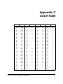
APPENDIX C: ASCII Table. . . . . . . . . . . . . . . . . . . . . . . . . . . . . . . . . . . . . . . . . . . . . . . . . . . . . . . 124
APPENDIX D: The PPG Library . . . . . . . . . . . . . . . . . . . . . . . . . . . . . . . . . . . . . . . . . . . . . . . . . . 125
APPENDIX E: Useful Bar Codes . . . . . . . . . . . . . . . . . . . . . . . . . . . . . . . . . . . . . . . . . . . . . . . . . 129
Glossary. . . . . . . . . . . . . . . . . . . . . . . . . . . . . . . . . . . . . . . . . . . . . . . . . . . . . . . . . 131
Index. . . . . . . . . . . . . . . . . . . . . . . . . . . . . . . . . . . . . . . . . . . . . . . . . . . . . . . . . . . . 135
vi Percon Program Generator User Manual
DRAFT—12/16/96
D:\DOCS\PPG\INTRO.FMD
Introduction
*I*INTRODUCTION*INTRODUCTION*INTRODUCTION*INTRODUCTION*INTRODUCTION*INTRODU
Percon Program Generator (PPG) is a Windows™ application that you can use to create
individualized programs for the Percon® family of portables. Rather than requiring use of a
complicated programming language, PPG provides an easy-to-follow user interface that
creates the program for you. You use menu commands and dialog boxes to build a flow
chart of the steps you want to include. PPG translates the flow chart into a program that
can be loaded into the portable.
You can use PPG to specify
• The text that appears in the portable's display area.
• The options that can be selected with the portable's function keys.
• The types of bar codes the portable can read.
• How the portable will accept input—via the scanner (wand), the input keys, the serial
port, or a combination of input sources.
• Where the portable stores data that is input.
• What to do if the wrong data or type of data is entered.
• How to format collected data for transfer to a PC file.
PPG makes it possible to customize your portable so that it suits your purposes exactly.
You can use any of the sample program files that are available (see appendix D), modify
an existing program, or create a program of your own from scratch.
1
DRAFT—12/16/96
D:\DOCS\PPG\INTRO.FMD
Introduction
Equipment Requirements
The following equipment is required to run PPG:
• An IBM PC or compatible computer with a 286 or better processor
• At least 1 megabyte of RAM (random access memory)
• At least 2 megabytes of hard disk space available
• A high-density, floppy disk drive (either 5¼" or 3½")
• A mouse
• DOS version 3.1 or later
• Microsoft® Windows version 3.0 or later
• A serial port (for loading your program into a portable)
You must have Microsoft Windows installed on your system. If it is not, install it following
the directions in your Microsoft Windows user’s guide. PPG runs only in Windows enhanced or standard mode, not in real mode.
Before You Start
Review the license agreement printed on the inside front cover of this manual and on the
envelope containing the program disk. It gives you permission to copy the program files for
backup purposes only. You may not make a copy for another person to use.
Also, fill out and mail the enclosed registration card. As a registered owner of the PPG program, you’ll be eligible for technical support and will be notified of program upgrades.
How to Use This Manual
This manual is divided into four chapters:
• Chapter 1, “Getting Started,” tells you how to install PPG on your hard disk and load it
into Windows. It gives you an overview of PPG concepts and usage and describes the
sample programs that come with PPG.
• Chapter 2, “Tutorial,” takes you step by step through the process of building a portable
program. By following the detailed instructions, you will create a simple program, use the
program emulator to debug the program, and load the program into a portable. After
scanning sample bar codes, you will then transfer the collected data back to your PC.
• Chapter 3, “User’s Guide,” gives you detailed information about using PPG. After reading through it, you can use it as a reference whenever you use PPG.
• Chapter 4, “Example Frames,” offers several ideas for PPG programs you can create.
2 Percon Program Generator User Manual
DRAFT—12/16/96
D:\DOCS\PPG\INTRO.FMD
Typographic Conventions
Appendixes at the end of the manual explain error messages you might encounter, give
you warranty information, provide an ASCII table for reference, describe files that come
with PPG, and provide several useful bar codes you can scan whenever necessary. A
glossary contains definitions of technical terms used in this manual.
Ideally, you should read this manual from front to back. The tutorial will give you a good
sense of what you need to do to create and use a portable program. The user's guide provides the details you need to do it. The example frames give additional helpful information.
Once you've read through the manual, you may want to return to the user's guide chapter
periodically to refresh your memory.
This manual assumes that you are familiar with Microsoft Windows. If you do not know
how to launch applications, select menu options, or use dialog boxes, refer to your
Microsoft Windows documentation.
Typographic Conventions
This manual presents special items in the text in the following ways:
• Words in italics are important terms you should know. Many of these terms are defined
in the glossary at the back of the manual.
• Words in bold are selections that appear in the PPG program, such as frame names,
node names, menu options, and fields and buttons in dialog boxes.
• Words in underlined bold are selections that you should make. These appear throughout the tutorial and in other places where you are instructed to take action.
• Words in underlined bold separated by an arrow (ð) are selections that you should
make in the specific order given. For example, FileðRun means select the File menu
and then select Run from that menu.
• Characters in courier bold are input characters that you should type. Input characters are usually given in lowercase (no capital letters), but you may enter them in lowercase, uppercase, or a combination. When input characters are given in uppercase or a
combination of lowercase and uppercase, type the characters exactly as shown.
• Characters in SMALL CAPITAL LETTERS are file names or directories.
• Characters in BOLD SMALL CAPITAL LETTERS are keyboard keys, such as ENTER. When
these are linked with a plus sign (for example, SHIFT+ENTER), hold down the first key
while pressing the second key once.
Percon Program Generator User Manual
3
DRAFT—12/16/96
D:\DOCS\PPG\INTRO.FMD
Introduction
Technical Support
If you have a question or problem that you are unable to resolve by reading the manual or
online help, you can call Percon Technical Support for assistance. Before you do so, however, be prepared to offer the following information:
• Your name and address.
• The program's version number (choose HelpðAbout PPG for this).
• The dates of the *.PHB and *.BHB files that came with PPG. (Use the File Manager or the
DOS DIR command for this.)
• The versions of DOS and Windows you are using. (Type ver at the DOS prompt for the
DOS version number. Choose HelpðAbout Program Manager from the Windows Program Manager for the Windows version number.)
• The amount of RAM and extended or expanded memory installed. (If you have DOS version 4.0 or later, type mem at the DOS prompt for this.)
• The amount of free space on your hard disk. (If you have DOS version 4.0 or later, type
dir at the DOS prompt for this.)
• A list of all peripherals installed, such as a serial mouse, printer, or modem.
• The contents of your CONFIG.SYS and AUTOEXEC.BAT files. (Use a Windows utility to view
these, or enter type filename.ext at the DOS prompt in the root directory.
Replace filename.ext with the name and extension of the file you want to read.)
• Your computer make and model.
• A concise, clear description of the problem, including any error messages that were
displayed.
To contact Percon Technical Support, call 503-344-1189 between 8 a.m. and 5 p.m.
Pacific time, Monday through Friday. If you prefer to correspond by letter, fax the Technical
Support Department at 503-344-1399 or write to:
Percon Incorporated
Technical Support Dept.
1720 Willow Creek Circle, Suite 530
Eugene, OR 97402-9171
4 Percon Program Generator User Manual
DRAFT—12/16/96 1:57pm
D:\DOCS\PPG\CH1.FMD
Chapter 1
Getting Started
*GETTING*STARTED*GETTING*STARTED*GETTING*STARTED*GETTING*STARTED*GETTIN
This chapter helps you prepare to use Percon Program Generator (PPG). It tells you how
to install the application on your hard disk and load and exit the program. It gives you an
overview of the application and how it integrates with your Percon portable. Finally, it describes three sample program files that come with PPG.
Installing PPG
The PPG installation program automatically creates a subdirectory on your hard disk,
copies your PPG files to it, and creates a program group for the application in Windows. To
run the installation program, complete the following steps:
1. Start Windows in either enhanced or standard mode.
2. Insert the PPG program disk in drive A.
If you use a floppy drive other than A, substitute its letter for A.
3. From the Windows Program Manager, select FileðRun.
4. In the Run dialog box, type a:install and press ENTER or select OK.
5
DRAFT—12/16/96 1:57pm
D:\DOCS\PPG\CH1.FMD
Chapter 1: Getting Started
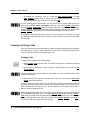
The installation program copies the PPG files to a subdirectory named \PPG31 off the root
directory of your hard disk. You can specify another directory during the installation, but it
must be immediately off the root directory (for example, \MYPPG). also creates a new program group in your Windows Program Manager. The Percon PPG31 program group contains the following items:
PPG is the Percon Program Generator application. This is the
application you'll use to create programs for your Percon portable.
PROG is used to transfer the program you created in PPG to the
portable. This utility is called automatically by PPG when you download
a program to the portable.
PTFER is used to transfer data between a PC and the portable. After
you've scanned bar codes with the portable, you can use this utility to
upload the data into a file on your PC. You can also use it to download
information stored in a PC file into the portable.
Loading and Exiting PPG
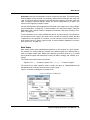
To work with PPG, select the PPG icon in the Percon PPG31 program group in Windows.
The PPG window appears, as shown in figure 1-1.
Figure 1-1. The PPG window
Control-menu box
Minimize button
Maximize button
6 Percon Program Generator User Manual
DRAFT—12/16/96 1:57pm
D:\DOCS\PPG\CH1.FMD
An Overview
You can use the Windows “drag-and-drop” technique to load PPG and a program source
file at the same time. Just use the mouse to drag the icon for the file from the Windows File
Manager onto the PPG icon.
To expand the window to fill the screen, select the Maximize button (see figure 1-1).
To temporarily remove the PPG window from your screen without exiting the application,
select the Minimize button (see figure 1-1). The window becomes an application icon at
the bottom of the Windows desktop. Double-click on the icon to bring the window back exactly as you left it.
To exit PPG, select FileðExit from the menu or double-click on the Control-menu box
(see figure 1-1). A dialog box appears, asking if you want to save any changes to the current file. Select Yes to save changes or No to discard them.
For further information on working in application windows, including using scroll bars and
selecting menu commands, refer to your Windows documentation.
An Overview
PPG helps you program your Percon portable to collect and store data in exactly the way
you want. Creating the program is only one part of the process, however. There are actually several steps involved:
Generating the Program This involves using PPG to create a flow chart of the datacollection process. Details of each step in the program are given in dialog boxes attached
to individual pieces of the flow chart.
Emulating the Program This is an optional step, but it can be helpful in testing a new
program. It uses a special Emulation window that simulates the effects of a program as
you run it. You can see text displayed on a model portable screen, simulate data input, and
“press” function keys. You can also view the contents of specified registers, set breakpoints at which to pause program execution, and view a “Trace” window that lists actions
taken. If there are problems with the program, you can correct them before you load the
program into your portable.
Downloading the Program Once your program is complete, you can connect your
Percon portable to your PC via a supplied cable and use the Download Program command to load the program into it. PPG compiles the program first, translating it into code
that is understood by the portable, and then sends the program over the cable to the portable. When it's done, you're ready to collect data using the portable.
Percon Program Generator User Manual
7
DRAFT—12/16/96 1:57pm
D:\DOCS\PPG\CH1.FMD
Chapter 1: Getting Started
Transferring Data After you've scanned a series of bar codes with the programmed portable, you can use the PTFER or PDTFER program that comes with PPG to transfer the
collected data to a file on your PC. The information is sent back through the connected
cable to a specified file on your computer. You can also transfer data, such as a “pick list”
for comparing input data, from the PC to the portable. Versions of this transfer program are
also available for Macintosh and UNIX computer systems (see chapter 4).
Most likely, the data you collect and store in a file will be nothing more than a series of
numbers or alphanumeric strings. You can transfer that data, however, into a data processing program that makes sense of it. For example, a scanned bar code may read 107028-0274. However, once that number is fed through a database or some other program
set up to interpret it, it could be translated into more readable information, such as
DECKERS THONG-ADULT, BLACK BRAID, $25.60.
Although it is possible to program the portable to translate scanned numbers into words,
this is usually a function of the program you use to process the data. You may load the
data into a spreadsheet program, for example, that you can use to perform calculations. Or
you might use a database program that keeps track of each item in your inventory. You can
use PPG to format collected data in a style that is accepted by most data processing programs.
Sample Program Files
PPG comes with three important sample files:
•
SAMPLE.SCR allows you to collect information with your portable, upload collected data to
a PC, and erase collected data. You will be using this file as you work through chapter 2.
•
SAMPLE2.SCR is a simple but complete data-collection program that allows the user to
enter data as either item-and-quantity values or just item values. The program also
stores data, uploads data, and erases data.
•
SAMPLE3.SCR is an expanded version of SAMPLE2.SCR that includes review and edit
capabilities. (This is the program that was loaded with your portable when you first got
it.)
You can use these files as is or modify them to suit your needs.
Several additional sample files are available from your PPG dealer (see appendix D).
Some of these files are just portions of programs demonstrating use of a specific node.
However, you can use any of these samples as a foundation for building a full-size
program.
8 Percon Program Generator User Manual
DRAFT—12/16/96 1:57pm
D:\DOCS\PPG\CH2.FMD
Chapter 2
Tutorial
*TUTORIAL*TUTORIAL*TUTORIAL*TUTORIAL*TUTORIAL*TUTORIAL*TUTORIAL*TUTORIA
This chapter eases you into using Percon Program Generator (PPG) by stepping you
through several specific procedures. Detailed instructions have you perform the following:
• View the flow chart of a sample program file.
• Load the program into your portable, collect data using the program, and upload the
data to your PC.
• Build a portable program of your own using PPG. The program will allow you to collect
and upload data using your portable.
• Use the Emulation window to debug your portable program.
• Load the new program into your portable and use it to scan bar codes.
• Upload the collected bar code data to a file on your PC.
• Create a template that divides a register into fields so that different types of values
(quantity and item) can be stored together as value pairs.
The entire tutorial should take approximately two hours to complete. Optional breaks are
inserted between sections, with instructions on saving and reloading your work. If you
can't complete the tutorial in one sitting, it's best if you stop at one of these points.
When you're done, you should have a solid understanding of the steps involved in programming and uploading data from the portable. You can then refer to chapter 3 for details
on creating your own customized portable program.
9
DRAFT—12/16/96 1:57pm
D:\DOCS\PPG\CH2.FMD
Chapter 2: Tutorial
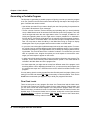
Studying a Sample Program
The easiest way to find out how a portable program works is to study an existing one. PPG
comes with three sample program files. We will take a look at the simplest of the three.
Later, you will load it into your portable and collect and upload data with it.
Complete the following steps to see how a sample program works:
1. If you're not already in PPG, start it now by going into the Percon PPG31 program
group in Windows and double-clicking on the PPG icon.
2. Click on the Maximize button at the right end of the title bar to expand the PPG window to a full screen.
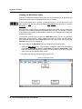
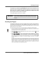
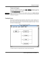
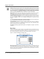
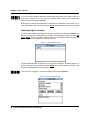
3. Choose FileðOpen and select sample.scr from the displayed list of files in the
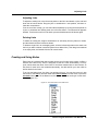
C:\PPG31 directory. Select OK to load the file into the PPG window (see figure 2-1).
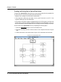
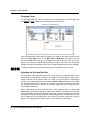
Figure 2-1. A sample program file
The program is initially shown at what is called the Frames level. This level contains a
flow chart of the program's main functions. Each rectangle in the chart is called a
frame. Most of the frames are linked together with arrows, indicating the flow of the
program. This sample program includes a Main Menu that branches off into three
tasks: collecting data, uploading data, and erasing data. Each of the tasks also allows
you to return to the Main Menu.
10
Percon Program Generator User Manual
DRAFT—12/16/96 1:57pm
D:\DOCS\PPG\CH2.FMD
Studying a Sample Program
The rectangle labeled “Pad Zeros” in the bottom-left corner is a subroutine. It doesn’t
link directly to the other frames, but it is jumped to from other parts of the program by
Call nodes.
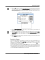
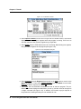
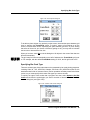
4. Move the mouse pointer to the Upload frame and click the right mouse button (or
select the frame and choose EditðRename from the menu). The Frame Name dialog
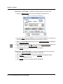
box will appear (see figure 2-2). This is where you define the text displayed in the
frame.
Figure 2-2. The Frame Name dialog box
You can also move to a frame by pressing the TAB key. The current frame is always indicated by a thick border. To select a frame, double-click on it with the left mouse button, or
move to it and then press the SPACEBAR.
5. Select Cancel or press ESC to close the dialog box.
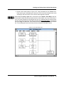
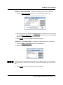
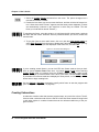
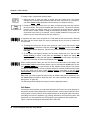
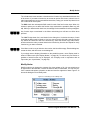
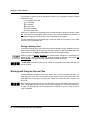
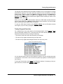
6. Each program frame has its own sublevel flow chart, stored at the Nodes level. This
enables you to break down a program into workable pieces, rather than dealing with
one giant flow chart. Select the Main Menu frame to view its flow chart in the Nodes
level (see figure 2-3).
Figure 2-3. The Nodes level of the Main Menu frame
Percon Program Generator User Manual 11
DRAFT—12/16/96 1:57pm
D:\DOCS\PPG\CH2.FMD
Chapter 2: Tutorial
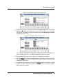
At the Nodes level, each rectangle in a flow chart is called a node. Nodes give the program detailed instructions, such as where to store scanned data. A Menu node presents a menu of options on the portable’s screen and specifies what actions will occur
when the user presses function keys associated with those options. You specify these
instructions by setting options in dialog boxes attached to the nodes.
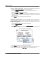
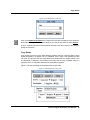
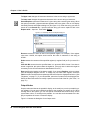
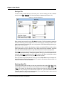
7. Select the Display : Options node to view its dialog box (see figure 2-4).
Figure 2-4. The Display : Options dialog box
8. Select Cancel or press ESC to exit the dialog box.
9. Select the Entry : Main Menu node (or any of the Exit To nodes) to return to the
Frames level of the program. (Entry and Exit nodes have double-line borders.)
You can also use ViewðFrames and ViewðNodes in the menu to jump between levels.
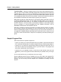
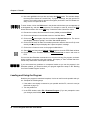
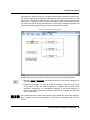
10. Select the Collect frame to view its Nodes level (see figure 2-5).
Figure 2-5. The Nodes level of the Collect frame
12
Percon Program Generator User Manual
DRAFT—12/16/96 1:57pm
D:\DOCS\PPG\CH2.FMD
Studying a Sample Program
Two Display nodes prompt the user to scan or enter first an item code (Display :
Enter Item) and then a quantity value (Display : Quantity). Both entered values are
displayed together on the screen (via the Output nodes) and are then copied to a file
for storage (via the Copy node).
The Input nodes send control back to the Main Menu if a function key is pressed. The
Call node jumps to the Pad Zeros subroutine back in the Frames level, padding the
input value with zeros, if necessary, to meet a required number of digits.
11. Select either the Entry : Collect or Exit To : Main Menu node to go back to the
Frames level.
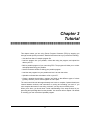
12. Select the Upload frame to view the nodes involved in uploading collected data (see
figure 2-6).
Figure 2-6. The Nodes level of the Upload frame
13. Select either the Entry : Upload or Exit To : Main Menu node to go back to the
Frames level.
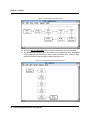
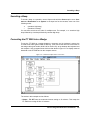
14. Select the Erase frame to view the nodes involved in it (see figure 2-7).
Percon Program Generator User Manual 13
DRAFT—12/16/96 1:57pm
D:\DOCS\PPG\CH2.FMD
Chapter 2: Tutorial
Figure 2-7. The Nodes level of the Erase frame
15. Select the Exit To : Main Menu node to return to the Frames level of the program.
16. The Pad Zeros subroutine (back in the Frames level) is called from within the Collect
frame. It adds zeros to the front of a value to make it contain a given number of digits.
Select the subroutine box to display its nodes (see figure 2-8).
Figure 2-8. The Nodes level of the Pad Zeros subroutine
14
Percon Program Generator User Manual
DRAFT—12/16/96 1:57pm
D:\DOCS\PPG\CH2.FMD
Programming Your Portable
17. Select Return : Pad Zeros to return to the Frames level.
By looking at all the pieces of this program file, you can get a general idea of how the program is put together. The Frames flow chart defines the major tasks of the program: Main
Menu, Collect, Upload, Erase, and Pad Zeros. Each frame and the subroutine is associated with a more detailed flow chart at the Nodes level. Together, the frames, subroutine,
and nodes work to outline every detail of the data-collection process.
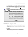
Want a Break?
If you're ready for a break, you can easily stop here. You haven't
made any changes that need saving, so you won't lose any work if
you exit PPG or turn off your computer.
Programming Your Portable
To use the program with your portable, you must download it from PPG to the portable.
Complete the following steps:
1. If you're returning from a break and had exited PPG, start the program now by doubleclicking its icon in the Window's Percon PPG31 program group.
2. Connect the 25-pin connector of your cable supplied with your portable to a serial port
on your computer. (If you have a 9-pin serial port, use a 25-to-9-pin adapter.)
3. Connect the other end of the cable to your portable.
4. Turn the portable on.
5. In the PPG window, select Fileð Download Program from the menu. If a dialog box
appears asking whether you want to save changes to the file, select Cancel to keep
the sample file intact. (This will abort the download. Close the sample file without saving it, reopen it, and select Fileð Download Program again.) If you do not have the
sample file loaded, select it from the dialog box that appears.
The Percon Portable Compiler window appears momentarily as PPG compiles the
program, translating it into a language understood by the portable.
While a program is downloading, you can work in another application window.
When compiling is complete, the Percon Portable Programmer window appears, displaying the message “Initiating Download.” If the connection is successful, the window
shows further messages as the program is loaded into the portable. The percentage
of completion is displayed as the programming progresses.
When downloading is complete, the portable will beep. You'll see the message “Portable successfully programmed” in the Percon Portable Programmer window, and the
program's Main Menu will appear in the portable’s display.
Percon Program Generator User Manual 15
DRAFT—12/16/96 1:57pm
D:\DOCS\PPG\CH2.FMD
Chapter 2: Tutorial
6. Double-click on the Percon Portable Programmer window's Control-menu box or
select Fileð Exit from the menu to close the window. (If downloading was unsuccessful, select Abort from the menu bar first.)
7. Double-click on the Percon Portable Compiler window's Control-menu box to close it.
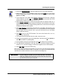
If You Have
Problems
If the message “Timeout Exceeded” appears or nothing happens at
all, PPG was unable to make the connection with the portable. It may
be that your serial port is not COM2. Click on the Comm command in
the Percon Portable Programmer menu bar until it reflects the number
of your COM (communication) port. Then select the Download Program command again. (The COM setting is automatically stored with
PPG and used the next time you download a program.)
Also, make sure that the cable is firmly connected at both ends. You
might try resetting the portable by pressing SHIFT+ENTER
(ALPHA+ENTER on the PT 2000) while you reinsert the battery.
Depending on the program currently loaded into the portable, you
may need to scan the following bar code or select options in the portable to place it in a mode for accepting downloaded data.
*/.*
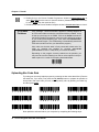
Uploading Bar Code Data
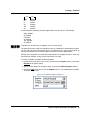
Try testing out the newly loaded program by scanning the bar codes that follow. (Remove
the cable first, if you wish.) First press the F2 (Collect) button to prepare the portable to
accept data. After each code you scan, enter a quantity value by pressing a number key,
and then press enter.
Now upload the collected data to your computer by completing the following steps:
16
Percon Program Generator User Manual
DRAFT—12/16/96 1:57pm
D:\DOCS\PPG\CH2.FMD
Uploading Bar Code Data
1. Click on the Minimize button in the PPG window to put it out of sight temporarily.
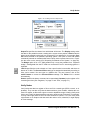
2. Back in the Windows Program Manager, double-click on the PTFER icon in the Percon
PPG31 program group. A blank PTFER window opens with three menu options: File,
Options, and Help.
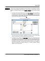
3. If your serial port is not COM2, select Optionsð Settings from the menu, select the
correct COM port, and select Ok. (The setting is automatically stored with the PTFER
program and is used the next time you transfer a file.)
4. Select Optionsð Connect to connect the program with the selected COM port. A
message appears in the window, saying the connection was successful. (If you don't
see this message, check the COM port setting. Make sure no other device is using the
COM port you specify, and try again.)
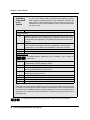
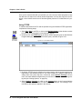
5. Select Fileð Receive. In the Receive File dialog box, type data. This specifies a new
file named DATA, with the default extension of .TXT, as the destination for the uploaded
data. By default, the file is stored in the C:\PERCON\LIB directory, but you can always
specify a different directory.
6. Select OK to return to the PTFER window. The name of the Receive file,
should appear in the title bar.
DATA.TXT,
7. If you disconnected the portable from the cable, reconnect it now.
8. Press F4 on the portable to return to the Main Menu, and then press F3 (for Upload) to
prepare the portable for uploading data.
9. At the portable’s prompt for uploading data, press F3 (for Yes) to begin uploading.
10. The alphanumeric translations of the bar codes you scanned are stored in the file
named DATA.TXT, and the message “File Received” appears in the PTFER window.
11. Select Fileð Exit to close the PTFER utility.
Once you've uploaded a file from the portable, you can put it to use with whatever application you use to work with scanned data. For example, you might have an application that
translates the numbers and letters in the bar codes into meaningful text.
Want a Break?
If you're ready for a break, you can easily stop here. You haven't
made any changes that need saving, so you won't lose any work if
you exit PPG or turn off your computer.
Percon Program Generator User Manual 17
DRAFT—12/16/96 1:57pm
D:\DOCS\PPG\CH2.FMD
Chapter 2: Tutorial
Building Your Own Portable Program
At this point, you should understand the general concepts behind creating and loading a
portable program, although many of the details have yet to be explained. In this section,
you'll create a simple portable program from scratch. It will allow you to collect data with
the portable and upload it to your PC. A menu that appears when you turn on the portable
gives you a choice of the two possible actions.
Creating Frames and Links
A program's frames define its general functions, such as collecting and uploading data.
Links connecting frames indicate program flow—how you move from frame to frame. The
details for the program are contained in the Nodes level for each frame.
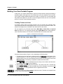
For your program, you will create three frames: Main Menu, Collect Data, and Upload
Data (see figure 2-9.). The program will start with the Main Menu frame, which offers access to the other frames. You can return to the Main Menu from either action frame.
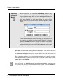
Figure 2-9. The Frames level of the program
Create the frames shown in figure 2-9 by completing the following steps:
1. To continue from the last section, double-click on the PPG icon at the bottom of the
Windows desktop. If you took a break and exited PPG, restart the program now by
double-clicking on its icon in the Window's Percon PPG31 program group. Click on the
Maximize button, if necessary, to expand the window to fill the screen.
2. Select Fileð New to clear the workspace area so that you can create a new flow chart.
(If prompted, answer No to saving changes.)
3. Select Createð Frame to draw the first frame. The cursor turns into a rounded box
labeled “FRAME”. Move it to the top-middle area of the workspace, and click the left
mouse button. A rectangle labeled “Frame1” appears at the cursor.
To adjust the position of a frame, just drag it with the mouse. To delete an unwanted frame
or node, select it and then press DELETE.
18
Percon Program Generator User Manual
DRAFT—12/16/96 1:57pm
D:\DOCS\PPG\CH2.FMD
Creating Frames and Links
4. Click the right mouse button (or select the frame and choose Editð Rename from
the menu) to display the Frame Name dialog box. Type Main Menu in the input box,
and press ENTER or select Ok. The frame now appears with the name “Main Menu.”
5. Now create the Collect Data frame. Select Createð Frame, move the FRAME box to
the bottom left area of the workspace, and click the left mouse button. Open the
Frame Name dialog box, type Collect Data, and select Ok.
6. Select Createð Frame, move the FRAME box to the bottom right area of the workspace, and click the left mouse button. Open the Frame Name dialog box, type
Upload Data, and select Ok.
You now have the three frames of your program. Next, you need to create the arrows, or
links, showing the flow of the program between the frames. Complete the following steps:
1. Select Createð Link. The cursor turns into a rounded box labeled “LINK”.
2. Move the LINK box to the Main Menu frame and click the left mouse button.
3. Move the LINK box to the Collect Data frame and click the mouse again. An arrow
appears, pointing from the Main Menu frame to the Collect Data frame.
4. Choose Createð Link, click on the Main Menu frame, and then click on the Upload
Data frame. A second arrow appears.
The links you created give the user access to either the Collect Data or Upload Data
frame from within the Main Menu.
To adjust a link, exit Create mode and use the mouse to drag the link’s arrowhead. To
delete a link, drag its arrowhead to a blank area and double-click the left mouse button.
From each of the action frames, you want to give the user access to the Main Menu. You
need to create links back to the Main Menu frame. This time you'll create jointed links that
bend at a 90 angle. Complete the following steps:
1. Select Createð Link and click on the Collect Data frame.
2. Instead of clicking directly on the other frame, move the LINK box straight up until it is
level with the Main Menu frame, and then click the left mouse button.
3. Now move the pointer to the Main Menu frame and click the left mouse button. A
jointed line appears.
Jointed links work just like straight links, but they give you more flexibility in their placement. If a jointed link appears jagged, drag its joint until its lines are perpendicular.
4. Use the same method to create a jointed link from the Upload Data frame to the Main
Menu frame.
Your screen should now look like the one shown in figure 2-9.
To redraw the screen and erase any extraneous lines, click in any blank area of the flow
chart.
Percon Program Generator User Manual 19
DRAFT—12/16/96 1:57pm
D:\DOCS\PPG\CH2.FMD
Chapter 2: Tutorial
Creating the Main Menu Nodes
Once you've defined the frames of a program, you use the Nodes level to specify the detailed parts of each frame. Each frame has its own set of nodes.
To go into the Nodes level of a frame, just double-click on it. You can also move to the
frame with the TAB key and then either select Viewð Nodes from the menu or press the
SPACEBAR.
Because nodes involve much more detailed information than frames, they are divided into
nine types, with a different dialog box associated with each type. For example, a Display
node specifies text to display on the portable’s screen; that text is entered into a dialog box
attached to the node.
In this section, you'll set up the nodes for the Main Menu frame. This is a very uncomplicated frame, simply creating a path to either of the other two frames. You will create a
Menu node that advances to the Collect Data frame if the user presses F3 and to the Upload Data frame if the user presses F4.
Set up the nodes for the Main Menu frame by completing the following steps:
1. Select the Main Menu frame. The workspace changes to show three double-lined
boxes: Entry : Main Menu, Exit To : Collect Data, and Exit To : Upload Data. These
nodes are created automatically by the links you set up at the Frames level. They offer
entry to and exit from the Main Menu nodes.
2. Reposition the existing nodes as shown in figure 2-10.
Figure 2-10. Repositioned nodes
20
Percon Program Generator User Manual
DRAFT—12/16/96 1:57pm
D:\DOCS\PPG\CH2.FMD
Creating the Main Menu Nodes
To move a node, just move the mouse pointer to the node, hold down the left mouse button, and drag the node with the mouse.
3. Select Create from the menu bar. Notice that the Create menu has changed. In place
of Frame and Subroutine, the nine types of nodes are listed (see figure 2-11).
Figure 2-11. The Create menu at the Nodes level
4. Select Menu. The pointer changes to a rounded box labeled “Menu”.
5. Click below the Entry : Main Menu node to create a Menu node there.
6. Change the node’s name to Options.
Changing a node’s name is identical to changing a frame’s name. (See step 4 on page 11
if you don’t remember how to change a frame’s name.) Notice that only the second line of
text on the node is changed. The first line always identifies the node's type.
7. Now you need to link the nodes together to indicate program flow. Select
Createð Link, and then select Createð Lock. This locks PPG into Create Link mode
so that you don't have to keep choosing Createð Link over and over.
8. Use the mouse to draw the links shown in figure 2-12. When you're done, choose
Createð Unlock or press ESC to exit Create Link mode.
Percon Program Generator User Manual 21
DRAFT—12/16/96 1:57pm
D:\DOCS\PPG\CH2.FMD
Chapter 2: Tutorial
Figure 2-12. The completed Main Menu nodes
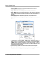
9. Select the Menu : Options node to bring up the dialog box for it. The dialog box
includes a text-entry area that is 16 characters wide and 4 lines deep, exactly the size
of the portable’s screen (see figure 2-13).
Figure 2-13. The Menu : Options dialog box
10. On the first line, type ---Main Menu---.
11. Press ENTER twice to jump to the third line, and type Collect Data.
12. Press ENTER again and type Upload Data on the last line, as shown in figure 2-13.
To the left of the text-entry area are check boxes for function keys used to select
options presented on the portable’s screen. The menu options you've created are
lined up with function keys F3 and F4 on the PocketReader. To initiate proper actions
for these keys, you need to specify which node to progress to for each.
22
Percon Program Generator User Manual
DRAFT—12/16/96 1:57pm
D:\DOCS\PPG\CH2.FMD
Saving Your Program
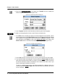
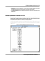
13. Select the F3 check box. A radio button appears next to the check box to show that this
is the active control. Click on the down-arrow button next to the input box at the bottom of the dialog box. A drop-down list appears, listing each node that this one is
linked to (see figure 2-14).
Figure 2-14. The drop-down list for Menu : Options
14. Select Frame Collect Data so that when the user presses
progress to the Collect Data frame.
F3,
the program will
15. Select the F4 check box. A new selected radio button appears. Click on the downarrow button next to the nodes input box, and select Frame Upload Data from the
displayed list. This moves the program to the Upload Data frame when the user
presses F4.
16. Select Accept to exit the dialog box, and select an entry or exit node to return to the
Frames level of the program.
Saving Your Program
Even though the program's not complete, it's a good idea to save it periodically as you
build it, for safety's sake. Select Fileð Save to save the program in a file. Enter
tutorial in the File Name input box of the displayed dialog box, and select OK. PPG
will add the extension .SCR automatically.
You have now completed the nodes of the Main Menu frame. These nodes display two options on the portable’s screen and allow the user to indicate a choice by pressing F3 or F4.
The program then checks to see which function key was pressed and passes control to either the Collect Data or Upload Data frame accordingly.
Percon Program Generator User Manual 23
DRAFT—12/16/96 1:57pm
D:\DOCS\PPG\CH2.FMD
Chapter 2: Tutorial
Want a Break?
If you're ready for a break, you can easily stop here. Since you just
saved your program in a file, you won't lose any work if you exit PPG
or turn off your computer.
Creating and Setting Up the Collect Data Nodes
The Collect Data frame allows the user to scan bar codes and enter data through the keys
of the portable. That data is temporarily stored in a register and then copied into a file,
which can be uploaded later to a PC.
You'll set up data-collection nodes to do the following:
• Display a message on the portable’s screen telling the user that the portable is ready to
accept data.
• Allow data input from the wand (scanner) or the portable’s keys, specify how to handle
each type of input, and name a register in which to store the data temporarily.
• Verify that the user input is valid and, if it is not, display an error message and sound a
beep.
• Copy the data from the temporary register to a data file and redisplay the initial message
asking for input.
In addition, you’ll create an option that will allow the user to return to the Main Menu by
pressing a function key.
Create nodes for the Collect Data frame by completing the following steps:
1. If you're returning from a break after exiting PPG, double-click on the PPG icon in the
Percon PPG31 program group. Then choose Fileð Open and select tutorial.scr from the file list. Select OK to load the file into the PPG window.
2. At the Frames level, select the Collect Data frame to access its Nodes level. Because
this frame has two links (one to it and one from it), there are two nodes initially created: Entry : Collect Data and Exit To : Main Menu. Reposition these nodes so that
the Entry node is in the upper left corner and the Exit node is at the bottom right.
If you click twice on either of these nodes, you'll end up back in the Frames level.
24
Percon Program Generator User Manual
DRAFT—12/16/96 1:57pm
D:\DOCS\PPG\CH2.FMD
Creating and Setting Up the Collect Data Nodes
3. Create all the nodes shown in figure 2-15, using commands on the Create menu.
Each node's type is indicated by the first line of text in the node. Rename each node
according to the second line of text. Link the nodes together as shown.
When linking the Verify : Input node, create the link to the Output : Error Beep node first.
This actually creates two links (a requirement for verify nodes), one on top of the other. If
you try to create another link, the program won’t let you. Instead, place the mouse pointer
over the arrow of the top link, press and hold down the left mouse button, and drag the
link to the Copy To : File node. Then release the mouse button and click it once to set the
link. The underlying link (from the Verify node to the Output node) stays in place.
Figure 2-15. The Collect Data nodes
Percon Program Generator User Manual 25
DRAFT—12/16/96 1:57pm
D:\DOCS\PPG\CH2.FMD
Chapter 2: Tutorial
THE DISPLAY : ENTER ITEM NODE You need to set up this node to display “Enter Item:”
on the first line of the portable’s screen and have the fourth line of the screen tell the user
to press F4 to return to the Main Menu. Complete the following steps to set up the node:
1. Select the Display : Enter Item node to open the node’s dialog box (see figure 2-16).
Figure 2-16. The Display : Enter Item dialog box
2. Type Enter Item: on the first line of the text entry area.
3. Press ENTER three times, and type Menu on the fourth line.
4. Select Accept to save your settings.
THE INPUT : ITEM NODE
Complete the following steps to set up this node:
1. Select the Input : Item node to display its dialog box (see figure 2-17).
Figure 2-17. The Input : Item dialog box
26
Percon Program Generator User Manual
DRAFT—12/16/96 1:57pm
D:\DOCS\PPG\CH2.FMD
The Input : Item Node
2. The Input From check boxes let you indicate which sources of input you want the portable to accept. Select the Scanner, Data Key, and 'Fn' Key check boxes. This will
allow the user to input data by scanning or pressing keys.
A radio button appears next to each selected check box. These buttons let you specify
a different Link To setting for each type of input allowed. In this case, you want wand
(scanner) and data-key input to link to the Verify : Input node and function key input
to return the user to the Main Menu.
3. Select the radio button next to the 'Fn' Key option, and then click on the down-arrow
button to the right of the Link To input box. A list of the nodes or frames that the Input
node is linked to is displayed.
4. Select Frame Main Menu. This tells the program to return to the Main Menu whenever the user presses a function key.
5. If you created the link to the Verify node first, all input types will link to that node by
default, and you won't need to adjust the settings. Otherwise, set the other selected
input types to Verify Input.
6. You want the user to see the data as it is being entered, so select the Echo to Display
check box. This displays the characters being entered with the data keys on the portable’s screen. To specify the exact position of the display on the screen, click on the
right-arrow button to the right of the check box. The Input Echo : Item dialog box
appears (see figure 2-18).
Figure 2-18. The Input Echo : Item dialog box
The Echo to Display option displays keyed-in characters only until the user presses the
ENTER key. Once the data is entered (or scanned), the program moves on through the next
nodes and redisplays the menu text, overwriting the echoed characters. To avoid this, you
would need to add Output nodes to reposition the cursor and display the echoed characters on a different line. This is demonstrated later in the tutorial.
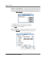
7. Select the Specify Position check box. Input boxes appear, allowing you to indicate
the exact row and column you want the echoed data to begin on. Position it on the
second row and first column. Columns and rows are numbered starting with 0 instead
of 1; so enter 1 in the Row box to indicate the second row and 0 in the Col box to indicate the first column (see figure 2-19).
Percon Program Generator User Manual 27
DRAFT—12/16/96 1:57pm
D:\DOCS\PPG\CH2.FMD
Chapter 2: Tutorial
n
Figure 2-19. The Input Echo dialog box
8. Select Accept. Now you need to create a special register for the input data to keep it
separate from other data.
A register is a temporary holding place for data. Unless you specify otherwise, the program stores input data in a register named Default Register. You can use numerous registers in a program, storing different types of information in different registers.
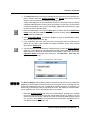
9. Click on the down-arrow button to the right of the Register input box in the subdialog
box below the main one. A list of the program's existing registers appears, as shown in
figure 2-20.
Figure 2-20. The list of the program’s registers
To delete an unwanted register, select it in the list, and then press DELETE.
28
Percon Program Generator User Manual
DRAFT—12/16/96 1:57pm
D:\DOCS\PPG\CH2.FMD
The Verify : Input Node
10. Type Inventory in the input box to create a new register named Inventory. The
Replace option (selected by default) clears existing data from the register before storing newly input data.
11. Select Accept to save your settings and exit the dialog box.
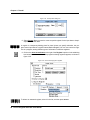
THE VERIFY : INPUT NODE The Verify : Input node ensures that the data entered is numeric. If the data isn’t numeric, the node passes control to the Output and Display nodes,
which sound a beep and display an error message. Complete the following steps to set up
this node:
1. Select the Verify : Input node to display its dialog box (see figure 2-21).
Figure 2-21. The Verify : Input dialog box
2. Select the Numeric radio button under the Type option. Because you don't want to
verify any specific number, leave the Match option set to None.
3. The Link On option is automatically set according to the links you create. The top link
always defines the Pass setting. It should be set to go to the Copy : To File node if
the data is numeric (Pass) and the Output : Error Beep node if it's not (Fail). If these
settings are reversed, click on the switch button next to the option to switch them.
4. You also need to tell the program what register to verify. Click on the down-arrow button next to the Register input box, and choose Inventory from the list. (You may need
to scroll down through the list to find it.)
5. Select Accept to save your settings and exit the dialog box.
Percon Program Generator User Manual 29
DRAFT—12/16/96 1:57pm
D:\DOCS\PPG\CH2.FMD
Chapter 2: Tutorial
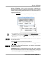
THE OUTPUT : ERROR BEEP NODE Now you need to set the Output : Error Beep
node to sound a beep. Complete the following steps:
1. Select the Output : Error Beep node to display its dialog box (see figure 2-22).
Figure 2-22. The Output : Error Beep dialog box
2. Select System as the Output To setting and Constant as the Source setting. In the
new input box that appears, enter the characters .+ (period and plus). This is a special code telling the program to sound a high beep. (You can enter .– to sound a low
beep.) Because the system already beeps once when a code is scanned, this causes
it to beep twice on an error.
3. Select Accept to save your settings and exit the dialog box.
THE DISPLAY : ERROR TEXT NODE You can have a special message appear when the
error beep is sounded. Select the Display : Error Text node, enter the text shown in figure
2-23, and select Accept.
Figure 2-23. The Display : Error Text dialog box
30
Percon Program Generator User Manual
DRAFT—12/16/96 1:57pm
D:\DOCS\PPG\CH2.FMD
The Copy : To File Node
THE COPY : TO FILE NODE Finally, you need to set up the Copy : To File node to copy
data from the Inventory register to a portable file for transmittal back to the PC. Each time
new data is scanned or entered, existing data in the Inventory register is replaced, and so
the data has to be copied and appended to a data file.
Complete the following steps:
1. Select the Copy : To File node to display the dialog box (see figure 2-24).
Figure 2-24. The Copy : To File dialog box
2. The copy Source is already set to Register. Click on the down-arrow button next to
the Register input box and select the Inventory register.
3. For the Destination setting, select File, and then enter Monthly Inventory in the
File input box.
Because this is a portable file and not a DOS file, the file name can include spaces and
more than eight characters.
4. Select Accept to save your settings and exit the dialog box.
Select either the Entry or Exit node to return to the Frames level of the program. Then select Fileð Save to save your changes to the file.
This time, because you’ve already named the file, PPG saves your changes without
prompting you for a file name.
The Collect Data nodes you created prompt the user to enter data, and they accept that
data either through scanning or data keys. If the data is verified as numeric, it is appended
to a data file named Monthly Inventory. If it's not numeric, the portable beeps and displays
an error message. Pressing a function key brings back the Main Menu.
Percon Program Generator User Manual 31
DRAFT—12/16/96 1:57pm
D:\DOCS\PPG\CH2.FMD
Chapter 2: Tutorial
Creating and Setting Up the Upload Data Nodes
The last frame, Upload Data, allows the user to copy collected data from the portable’s file
to a file on the PC. You will set up nodes that do the following:
• Display a menu asking if the user wants to upload data.
• If the response is Yes (F3), send data over the serial connector to the PC. If the
response is No (F4), exit to the Main Menu.
• If the output is successful, display a message saying so for 45 seconds (or until the user
presses a key), and then clear the portable’s file and return to the Main Menu. If the output is unsuccessful, beep and display an error message, and then redisplay the prompt.
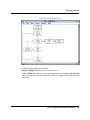
Create nodes for the Upload Data frame by completing the following steps:
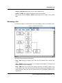
1. Select the Upload Data frame to move into its Nodes level.
2. Reposition the Entry and Exit nodes as shown in the completed flow chart in figure
2-25.
3. Create and name the new nodes shown in figure 2-25, and add the links as shown.
Figure 2-25. The Upload Data nodes
32
Percon Program Generator User Manual
DRAFT—12/16/96 1:57pm
D:\DOCS\PPG\CH2.FMD
The Menu : Confirmation Node
When creating the links from the Output : to PC node, create the link to the Output :
Error Beep node first. Two links are automatically created, one on top of the other. Place
the mouse pointer over the arrow of the top link, press and hold down the left mouse button, and drag the link to the Display : Successful node. The underlying link stays in
place.
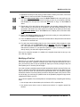
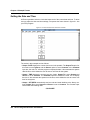
THE MENU : CONFIRMATION NODE
Complete the following steps to set up this node:
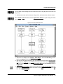
1. Select the Menu : Confirmation node to open its dialog box, and enter the text shown
in figure 2-26. (Be sure to leave the second line blank.)
Figure 2-26. The Menu : Confirmation dialog box
2. Select the F3 check box. Then click on the down-arrow button next to the input box,
and select Output to PC from the drop-down list. This will make the portable begin
outputting data when the user presses F3.
3. Select the F4 check box, and select Frame Main Menu from the drop-down list. This
will redisplay the Main Menu when the user presses F4.
4. Select Accept to save your settings and exit the dialog box.
Percon Program Generator User Manual 33
DRAFT—12/16/96 1:57pm
D:\DOCS\PPG\CH2.FMD
Chapter 2: Tutorial
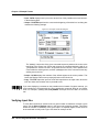
THE OUTPUT : TO PC NODE
Complete the following steps to set up this node:
1. Select the Output : to PC node to open its dialog box (see figure 2-27).
Figure 2-27. The Output : to PC dialog box
2. Select the Serial setting for Output To. This will send the output to the serial port of
the portable, which should be connected to the serial port of the PC.
3. Make sure the Link On Success option is set to Display Successful and Failure is
set to Output Error Beep.
4. For the Source option, select File. Then click on the down-arrow button next to the
File input box, and select Monthly Inventory from the drop-down list.
5. Select Accept to save your settings and exit the dialog box.
THE OUTPUT : ERROR BEEP NODE
Complete the following steps to set up this node:
1. Select the Output : Error Beep node to open its dialog box.
2. Select System as the Output To setting and Constant as the Source setting.
3. Enter .+ in the Source input box.
4. Select Accept to save your settings and exit the dialog box.
34
Percon Program Generator User Manual
DRAFT—12/16/96 1:57pm
D:\DOCS\PPG\CH2.FMD
The Menu : Error Text Node
THE MENU : ERROR TEXT NODE
Complete the following steps to set up this node:
1. Select the Menu : Error Text node and enter the text shown in figure 2-28.
Figure 2-28. New text for the Menu : Error Text node
2. Select the F3 check box and choose Output to PC from the drop-down list. Select F4
and choose Frame Main Menu. This will try outputting again if the user presses F3
and return to the Main Menu if the user presses F4.
3. Select Accept to save your settings and exit the dialog box.
THE DISPLAY : SUCCESSFUL NODE
Complete the following steps to set up this node:
1. Select the Display : Successful node to open its dialog box.
2. Enter the text shown in figure 2-29.
Figure 2-29. Display text for successful upload
A Menu node is not necessary here, because only one option is given, and it is executed if
any function key is pressed, not just F4. The Input node that follows this one will see to
that.
3. Select Accept to save your settings and exit the dialog box.
Percon Program Generator User Manual 35
DRAFT—12/16/96 1:57pm
D:\DOCS\PPG\CH2.FMD
Chapter 2: Tutorial
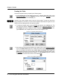
THE INPUT : TIMEOUT DISPLAY NODE
Complete the following steps to set up this node:
1. Select the Input : Timeout Display node to open its dialog box.
2. Select the Scanner check box to turn it off. (There should be no x in the box.)
3. Select the 'Fn' Key and TimeOut check boxes.
4. Enter 45 in the Seconds input box that appears next to TimeOut. This instructs the
program to return to the Main Menu if the user presses a function key or if 45 seconds
pass with no input.
5. Select Accept to save your settings and exit the dialog box.
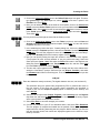
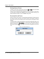
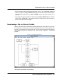
THE MODIFY : ERASE FILE NODE Once you've uploaded data from your portable file,
you'll probably want to erase its contents. Otherwise, further data you collect will be appended to the data you just uploaded, and your data file will quickly grow out of control.
Complete the following steps:
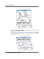
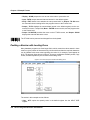
1. Select the Modify : Erase File node to open its dialog box.
2. Select the Delete radio button.
3. Select File as the Data setting, and choose Monthly Inventory from the drop-down
file list (see figure 2-30).
Figure 2-30. The Modify : Erase File dialog box
4. Select Accept to save your settings and exit the dialog box.
The nodes for uploading data are now complete. Select either the Entry or Exit node to return to the Frames level. Then select Fileð Save to save your changes to the file.
36
Percon Program Generator User Manual
DRAFT—12/16/96 1:57pm
D:\DOCS\PPG\CH2.FMD
Emulating the Program
The nodes that you created for the Upload Data frame ask the user for confirmation of the
upload task. If the user answers Yes, it outputs the data file over the serial port. If the upload is successful, a message is displayed, the portable’s file is cleared, and the Main
Menu returns. If the upload is unsuccessful, the program beeps, displays an error message, and gives the user the option of trying again.
Your portable program should now be complete.
Want a Break?
If you're ready for a break, you can easily stop here. Since you saved
your file, so you won't lose any work if you exit PPG or turn off your
computer.
Emulating the Program
The Emulation window lets you test your program before you load it into the portable. It
runs through your program step by step, displaying exactly what would appear on your
portable screen and responding to your input just as the portable would. You can see if the
program will work as you expected.
Use the Emulation window now to test your program. Complete the following steps:
1. If you're returning from a break and had exited PPG, double-click on the PPG icon in
the Windows Percon PPG31 program group.
2. Select Fileð Open, choose tutorial.scr from the file list, and select OK to load
the file into the PPG window.
3. Select Viewð Emulation to open up the Emulation window. By default, the window is
modeled after the face of a Percon PocketReader™ portable, with the display screen
on the right and keys below and to the left (see figure 2-31). If you choose PT 2000
from the Options menu, however, the window changes to look like a PT 2000™
portable.
In either case, the name of the emulated program's current frame and node are displayed in the title bar. Commands in the menu bar let you run the program and set
emulation options. An input box displays data you enter, and a check box lets you
enable or disable the timeout setting, if any. When timeout is enabled, the timeout
value is counted down in the adjacent input box.
Percon Program Generator User Manual 37
DRAFT—12/16/96 1:57pm
D:\DOCS\PPG\CH2.FMD
Chapter 2: Tutorial
Figure 2-31. The Emulation window
4. Select Optionsð Watch from the menu to open the PPG Watch window. This window
displays the contents of given registers while the program is running. You'll use it to
view the contents of the Inventory register as you input data.
5. Select SetUp from the PPG Watch menu bar. The Setup Watch dialog box appears,
listing all named registers for the program (see figure 2-32).
Figure 2-32. The Setup Watch dialog box
6. Select Inventory from the Registers list and click on the Add button to move it to the
Watch list below it. Then select Default Register from the Watch list and select
Remove to delete it from the list. Select Ok.
7. Select Run from the Emulation window's menu bar to start the program. The portable’s screen area displays the Main Menu you set up, and the menu bar changes to
a single command (see figure 2-33). In addition, the function keys (F1–F4) are no
longer dimmed, meaning that they are now available for use.
38
Percon Program Generator User Manual
DRAFT—12/16/96 1:57pm
D:\DOCS\PPG\CH2.FMD
Emulating the Program
Figure 2-33. The Main Menu displayed in the Emulation window
8. Click on the F3 button in the window to choose the Collect Data option. Text from the
Display : Enter Item node appears in the screen area, prompting you to input data,
and the menu bar changes to show the following commands: Wand, Serial, Timeout,
and Stop (see figure 2-34).
Figure 2-34. The Emulation window prompting for input
The first three commands let you simulate a specific type of input; only Wand input
can be selected at this point. The Stop command halts program emulation.
9. Enter 123456 in the input box by clicking on the data keys on the screen.
10. Select the Wand menu option to emulate scanning. The number is stored in the Inventory register (as you can see by checking the PPG Watch window), and the input box
is cleared for further input.
11. Enter 98765 in the input box and click on the ENTER button in the window to emulate
keying in a number. This number replaces the previous one in the Inventory register,
and the input box is cleared.
Percon Program Generator User Manual 39
DRAFT—12/16/96 1:57pm
D:\DOCS\PPG\CH2.FMD
Chapter 2: Tutorial
12. Now enter Q1234 in the input box and select the Wand option. The emulator beeps,
the screen area shows the “Invalid Entry. Try Again” message, and the input box is
cleared. The invalid number is stored in the register (as shown in the PPG Watch window), but it is not copied to the file.
To enter a letter, click on the Shift button in the window until the letter you want appears on
its designated key, and then click on that key. For example, to enter Q, click on the Shift
button twice and then click on the PQR key, in which the letter Q should be visible.
13. Reenter the number, this time without the letter (1234), and select Wand.
14. Click on the F4 button in the window to return to the Main Menu.
15. Click on the F4 button again, this time to choose the Upload Data option. The screen
area displays “Ready to Upload?” and offers Yes and No options.
16. Click on the F3 button for Yes. The emulator pretends to write the data to a file (it never
actually alters any files) and displays the “Upload complete” message.
17. Click on the F4 button to return to the program's Main Menu.
18. Select Stop, and then select Optionsð Watch again to close the PPG Watch window.
19. Double-click on the Emulation window's Control-menu box to close it and return to
PPG.
You can use other Emulation commands to run only the next step of a program, set breakpoints at which you want to pause the program, and display a “Trace” window that documents every action taken. See chapter 3 for details.
If you encountered any problems or unexpected results as you ran the program in the
Emulation window, you should recheck your program against the steps in the “Building
Your Own Portable Program” section.
Loading and Using the Program
Now that your program is tested and complete, it's time to load it into the portable and try it
out. Complete the following steps:
1. If the cable is not already connected to your portable and the PC, connect it now (as
described on page 15).
2. Turn the portable on.
3. In the PPG window, select Fileð Download Program. (If you are prompted to save
your changes, answer Yes.)
40
Percon Program Generator User Manual
DRAFT—12/16/96 1:57pm
D:\DOCS\PPG\CH2.FMD
Loading and Using the Program
The Percon Portable Compiler window appears while PPG compiles the program.
When compiling is complete, the Percon Portable Programmer window displays the
message “Initiating Download.” If connection is successful, the program is loaded into
the portable. When downloading is complete, the message “Portable successfully programmed” appears in the Percon Portable Programmer window, and the program's
Main Menu is displayed on the portable’s screen.
If You Have
Problems
If a few seconds pass with no messages, PPG was unable to make
the connection with the portable. Select the Comm2 command on the
Percon Portable Programmer menu bar to select a different serial
port, and then select the Download Program command to try again.
Also, make sure that the cable is firmly connected at both ends. You
might try resetting the portable by holding down Shift+Enter while
you reload the battery.
If you loaded a different program into your portable since downloading
the sample program earlier, the portable may not be set to allow serial
input, or the serial parameters may not be set correctly. In this case,
scan the following bar code or select options in the portable to prepare it for downloading.
*/.*
4. Double-click on the Percon Portable Programmer window's Control-menu box or
select Fileð Exit to close the window. (If downloading was unsuccessful, choose
Abort from the menu bar first.)
5. Double-click on the Control-menu box in the Compiler window to close it.
6. Disconnect the portable from the cable, and press the F3 key to begin collecting data.
7. Scan the following bar codes at least once. Each time a code is scanned correctly, you
should hear a single beep. (You won't see the scanned codes on the portable’s
screen, because they are overwritten by the redisplayed menu once the data is input.)
When you scan the last code, which contains an alphabetic character, you'll hear a
double beep, indicating an error.
Percon Program Generator User Manual 41
DRAFT—12/16/96 1:57pm
D:\DOCS\PPG\CH2.FMD
Chapter 2: Tutorial
8. Now enter the following codes using the portable’s data keys. The portable will beep
each time you press a key. Press ENTER after each complete number.
12345
67890
98765
54321
9. Press the F4 key to return to the program's Main Menu.
Uploading Data from the Portable
Now use the PTFER program to upload the data you collected to your computer. Complete
the following steps:
1. Click on the Minimize button in the PPG window to temporarily put it out of sight.
2. Back in the Windows Program Manager, double-click on the PTFER icon in the Percon
PPG31 program group to display the PTFER window.
3. If your serial port is not COM2, select Optionsð Settings from the menu, select the
correct COM port, and select Ok.
4. Select Optionsð Connect. A message appears in the window, saying the connection
was successful.
5. Select Fileð Receive. In the Receive File dialog box, type the file name invntory
and select OK. The file name appears in the PTFER window's title bar, with the .TXT
extension added automatically.
6. Reconnect the cable to the portable, and press the F4 key (for Upload Data) on the
portable.
7. Press the F3 key (for Yes) to confirm uploading.
The data that you scanned and entered is immediately transferred from the portable’s
file called “Monthly Inventory” to a DOS file on your PC called INVNTORY.TXT.
If this doesn’t happen, check your connections and COM port setting, and try again. The
portable defaults to 9600 baud, no parity, 8 data bits, and 1 stop bit. To reset the portable
to these defaults, scan the following:
*$+$-C8EE*
8. Double-click on the PTFER window's Control-menu box or choose Fileð Exit to
close the window.
For complete information about PTFER (including running it with command line options),
see “Using PTFER,” beginning on page 94.
42
Percon Program Generator User Manual
DRAFT—12/16/96 1:57pm
D:\DOCS\PPG\CH2.FMD
Creating and Using Templates
Creating and Using Templates
The programs you've worked with so far handle singular information: You scan or enter
one code at a time, and the data is stored one entry per line. But suppose you wanted to
collect sets of different types of data. If you were taking inventory, for example, rather than
scanning each item in a group of identical products, you might want to scan only one of
them and then use the data keys to record the number of items in the group.
You could add another Input node to the Collect Data frame of your program to store the
types of data in different registers, but the data file you would end up with would have code
numbers and quantity numbers on alternate lines, as in the following:
3849293
5
9385834
12
9848495
8
This arrangement of data would be difficult for an inventory or database program to interpret. Most programs expect to see related values on the same line, as in the following:
3849293, 5
9385834, 12
9848495, 8
In this arrangement, each line is referred to as a record, and each item on the line is called
a field. The database program can be set up to treat the first field as an inventory code and
the second as a quantity value.
The way you tell a portable program to arrange data as fields in records is with a template.
A template defines the structure used to access data. Most often, a template is used to
combine values in two different registers as fields in a single register. The fields are either
set to a fixed length (so that they appear in columns in the data file), or they are allowed a
variable length with a separator (such as a comma) separating them. However, you can
also use a template to break apart data stored in a register into separate fields.
You will incorporate a template into the TUTORIAL program to collect and store quantity
values along with each item number. To do this, you'll add the following new nodes to the
existing TUTORIAL program:
• A new Display node that will prompt the user to enter a quantity value after an item number is entered
• A new Input node that will use a template to store the quantity value in a register field
• Two Output nodes that will display the last-entered item and quantity values as a pair
You'll also alter the existing Input node to use a template.
Percon Program Generator User Manual 43
DRAFT—12/16/96 1:57pm
D:\DOCS\PPG\CH2.FMD
Chapter 2: Tutorial
Creating the New Nodes
Create the new nodes by completing the following steps:
1. Double-click on the PPG icon at the bottom of the Windows desktop to reopen PPG.
2. The TUTORIAL program file (TUTORIAL.SCR) should still be loaded, but if it isn’t, use
Fileð Open to load it. (Your screen will have links not shown in the figure.)
3. At the Frames level, select the Collect Data frame, and reposition the nodes as shown
in figure 2-35.
Figure 2-35. The repositioned Collect Data nodes
4. Delete the link from the Verify node to the Copy node.
To delete a link, use the mouse to drag its arrowhead away from a node, and double-click
the left mouse button.
5. Adjust the links from the Copy node to the Display node and from the Input node to the
Exit node so that they are no longer jointed.
44
Percon Program Generator User Manual
DRAFT—12/16/96 1:57pm
D:\DOCS\PPG\CH2.FMD
Creating the New Nodes
You can either delete existing links and create new ones or drag the joints of the links until
they line up.
6. Add the new nodes and links shown in figure 2-36, and rename the nodes as shown.
Select Createð Lock and then click the right mouse button to cycle through the items
you can create.
Figure 2-36. The new Collect Data nodes
7. Select the new Display node (Display : How Many?), and enter How Many? on the
first line and Menu on the fourth. Then select Accept.
8. Skip over the two Output nodes for now, and select the new Input node (Input : Quantity). Select the Data Key and 'Fn' Key check boxes, and select the Scanner option to
turn it off. Link the 'Fn' Key setting to Frame Main Menu and the Data Key setting to
Copy to File.
9. Select the Echo to Display check box and click on the right-arrow button next to it.
Select the Specify Position option and enter 1 in the Row input box and 0 in the Col
box. Then select Accept.
Percon Program Generator User Manual 45
DRAFT—12/16/96 1:57pm
D:\DOCS\PPG\CH2.FMD
Chapter 2: Tutorial
Creating the Fields
Create the template fields by completing the following steps:
1. In the subdialog box at the bottom of the Input : Quantity dialog box, click on the
down-arrow button next to the Register input box, and choose Inventory from the
drop-down list. (Do not select Accept yet.)
Inventory is the same register used to store the item number. To keep one value from
being overwritten by the other, you will create a template that divides the register into two
fields: one for the quantity and one for the item number.
2. To create the template name, select the Field radio button in the subdialog box. Two
new input boxes appear: Template and Field. Click on the right-arrow button next to
the Template input box to display the Define Template dialog box (see figure 2-37).
Type Combine in the Template input box for the new template’s name.
Figure 2-37. The Define Template dialog box
3. Now create the field names and define their lengths. Click on the right-arrow button
next to the Define Fields input box to display the Define Field dialog box (see figure
2-38). You will define two fields for this template: Item and Quantity. Type Item in the
Field input box. Because you don't want to limit this field to any specific length, select
the Variable radio button and enter a comma (,) in the Delimiter input box. This will
separate the two values with a comma. Then select Done.
Figure 2-38. The Define Field dialog box
46
Percon Program Generator User Manual
DRAFT—12/16/96 1:57pm
D:\DOCS\PPG\CH2.FMD
Creating the Fields
4. Click on the right-arrow button next to the Define Fields input box again. This time,
type Quantity in the Field input box, select Variable, and enter a space in the
Delimiter box. Select Done.
5. Next, you will define the order of the fields in the template. Click on the down-arrow
button next to the Define Fields input box to see your new fields included in the list of
possible fields. Select Item from the list, and select the Add button to add it to the list
in the Fields input box. Click on the down-arrow button again and select Quantity.
Then select Add.
You may need to scroll through the list to find the fields you want.
6. Click on the down-arrow button next to the Fields input box to see both Item and
Quantity listed as fields for the Combine template. Select Done. You can now use the
templates and fields in the nodes.
7. In the subdialog box below the Input : Quantity dialog box, click on the down-arrow
button next to the Template input box, and choose Combine. Set the Field input box
to Quantity. This tells the program to store the value input after the “How Many?”
prompt in the Quantity field of the Inventory register. Select Accept.
8. Now you can specify storing the input item number in the Item field of the register.
(The program will work correctly whether or not you perform this step.) Select the
other Input node (Input : Item) and select the Field radio button in the Register subdialog box. Select Combine from the Template drop-down list, and then select Item
from the Field drop-down list. Select Accept.
9. The two new output registers make it possible to display the Item value without overwriting the “How Many?” prompt. Select the first one (Output : Position), and select
the Constant radio button in the dialog box. Then enter the following in the input box
that appears:
\x1B[2;0f
Enter the characters exactly as shown. (The eighth character is a zero, not the letter O.)
This character string is a special code recognized by PPG. It positions the cursor in
the first column of the third row. (Further output commands are described in
chapter 3.) Be sure the Output to Display option is selected (it’s the default), and
select Accept.
10. Select the other Output node (Output : Register), select Inventory from the Register
drop-down list, and select Accept. This displays the contents of the Inventory register
at the cursor position on the portable’s screen.
11. Select Fileð Save to store the changes you've made.
12. Connect the portable to your PC as described earlier, and select Fileð Download.
The new program is compiled and loaded into the portable. When it's done, you can
experiment with collecting data using the new program. Notice that after you enter the
item and quantity values, both entries are displayed together on the third line, separated by a comma.
Percon Program Generator User Manual 47
DRAFT—12/16/96 1:57pm
D:\DOCS\PPG\CH2.FMD
Chapter 2: Tutorial
This is the end of the tutorial. What you've learned here should give you the understanding
and background you need to develop your own portable programs. The next chapter will
give you all the specific information required. It covers every detail of each available
option.
48
Percon Program Generator User Manual
DRAFT—12/16/96 1:57pm
D:\DOCS\PPG\CH3.FMD
Chapter 3
User’s Guide
*USERS*GUIDE*USERS*GUIDE*USERS*GUIDE*USERS*GUIDE*USERS*GUIDE*USERS*GUID
This chapter gives you details on every command and option available within Percon
Program Generator (PPG). The following subjects are covered:
• Using online help and working with a mouse
• Creating frames, subroutines, nodes, and links to build a program
• Making adjustments to a program flow chart
• Setting program options, such as the types of bar codes to be read
• Saving, opening, closing, and printing program flow chart files
• Using the Emulation window to debug a program flow chart
• Downloading a program into the portable
• Transferring data between the portable and the PC
• Using templates and files to organize and format collected data
Once you've read this chapter, you may want to return to it from time to time for information
about procedures and options.
Using Online Help
While you're working in PPG, you can easily access online help for specific commands,
procedures, or concepts. There are four ways you can get help:
49
DRAFT—12/16/96 1:57pm
D:\DOCS\PPG\CH3.FMD
Chapter 3: User’s Guide
• Press F1. The help screen that appears depends on where you are in the program and
what you're doing. If a menu command is highlighted, the help screen describes that
command.
• Select the Help button. Most dialog boxes in PPG include a Help button. Select this
button to display help about the dialog box's options.
• Press SHIFT+F1. A question mark appears next to the mouse pointer. Use this pointer to
click on an area of the screen you want help on.
• Select a command from the Help menu. Commands in this menu take you to different
areas of the online help system. Contents displays the main help screen, which lists
general help topics. About PPG displays a Percon identification screen that shows the
version number of your program.
All online help screens are linked together via jumps, which are graphics or text that lead
to a different help screen when selected. Text jumps are identified by a different color and
an underline. When you point to a jump, the pointer changes to a hand shape, as shown in
figure 3-1. Click the left mouse button while pointing to a jump to display complete information on the topic.
Figure 3-1. The help pointer over a jump
When you click on a jump that has a dashed underline, a pop-up window opens. To close
a pop-up window, click a mouse button or press a key.
The PPG help window contains its own menu bar of commands. You can use them to load
another help file, print help screens, copy a help screen to the Clipboard, insert a graphic,
set bookmarks for saving your place, display help on using help, and keep the help window
from being covered by other windows.
The help window also includes a set of command buttons across the top. You can select
these buttons to jump to the help contents screen, search for help on a given topic, jump to
the previously displayed screen, and display a history of displayed screens that you can
jump back to.
For detailed instructions on using all of the online help commands and features, press F1
from within the help window or select Helpð How to Use Help from the help menu bar.
When you're done using help, select Fileð Exit or, if you think you will want to use help
again, press ALT+TAB. The help window does not close then, but instead it moves behind
the PPG window. When you select help (or press ALT+TAB) again, the help window moves
to the front.
50
Percon Program Generator User Manual
DRAFT—12/16/96 1:57pm
D:\DOCS\PPG\CH3.FMD
Using the Mouse
Using the Mouse
Like most Windows applications, PPG makes extensive use of the mouse. Table 3-1
shows standard mouse techniques that have special effects in PPG.
Table 3-1. Mouse Techniques
Mouse Action
Effects
Left button,
single click
• On an object, such as a menu command or frame, selects that
object.
• In Create mode, creates the object specified by the cursor label at
the cursor position.
• When creating a link, specifies the beginning or end of the link or a
joint.
• With two or more overlapped links selected, selects the next link in
the stack.
• At the Frames level, enters the Nodes level for the selected frame.
• On an Entry or Exit node, reverts to the Frames level.
• On any other node, opens the node's dialog box.
• While holding a link, deletes that link.
• On an object, moves the object with the pointer until the button is
released.Not on an object, draws a rectangle on the screen. All
objects within the rectangle are selected and can be moved or
adjusted at once.
• On a frame or node, opens the Name dialog box.
• In Create mode, selects the next option on the Create menu.
• Places PPG in Create mode.
Left button,
double click
Left button,
press and hold;
drag
Right button,
single click
Right button,
double click
Depending on what you're doing with the mouse, the pointer changes to reflect the current
action:
If you're making a simple selection or dialog box entry, the pointer is
the standard arrowhead.
If you're creating an object, the pointer appears as a rounded box with
a label that identifies the type of object you're creating.
When you're moving a frame, node, or link, the pointer changes to an
open hand.
When you press SHIFT+F1, a question mark is added to the standard
pointer, which you can position on a part of the screen you want help
on. When you click the left mouse button, online help for that area
appears.
Percon Program Generator User Manual 51
DRAFT—12/16/96 1:57pm
D:\DOCS\PPG\CH3.FMD
Chapter 3: User’s Guide
Generating a Portable Program
The first step in generating a portable program is figuring out what you want the program
to do. Put yourself in the end user's shoes and walk through the steps of the imagined program. Consider each action involved.
• How will the user start? Do you want to identify the user first by asking for a password or
ID number? What about a log-on message?
• To offer a choice of actions, such as collecting and uploading data, you should probably
set up a Main Menu that can be accessed from different areas of the program. List in this
menu each general action the user might want to take. For example, in addition to collecting and uploading data, the user might want to erase a portable file or download a
file from the PC. If an action will be taken only in a specific area of the program, however,
you may not want it on the Main Menu. You can offer the option through another menu
later. You may want to have the F8 key in the Main Menu bring up a sign-on display
showing the name of your program and its version number or creation date.
• In your mind, move through the individual steps involved in each major action. For example, will the user be collecting different types of data at different times? If your inventory
is divided into categories, you might want the user to identify the category before collecting the data. This could be done with a “collection” submenu. For each action you would
take as a portable user, imagine the options you would expect to have and the messages you would expect to appear on the screen.
• In what order will the actions be taken? Is there an obvious direction to the program? For
example, a user would normally collect data and then upload it. This order should be
reflected in the Main Menu and in the program flow.
• Are there steps that you might want to access from different areas of the program, such
as writing data to a file or displaying the date? If so, you can save time and program size
by putting these steps into a subroutine that can be called from different areas of the
program.
You may want to sketch out the program flow chart first with pencil and paper. When you're
ready, go into PPG and choose Fileð New, if necessary, to clear the window. Then use the
Create menu commands (see pages 53–78) to build your program's flow chart.
Flow Chart Levels
There are two levels to every program flow chart: the Frames level and the Nodes level.
You start in the Frames level, creating a frame for every major function of the program, and
you use links to hook the frames together in the way that the program flows. For each
frame in the chart, you also build a set of nodes that break down the frame's function into
detailed steps. To access the Nodes level of a frame, double-click on the frame with the
left mouse button, or select it and choose Viewð Nodes. To return to the Frames level,
select one of the Exit or Entry nodes or choose Viewð Frames.
52
Percon Program Generator User Manual
DRAFT—12/16/96 1:57pm
D:\DOCS\PPG\CH3.FMD
Testing Your Program
Testing Your Program
Once you've completed the flow chart, use the Viewð Emulation command to load it into
an Emulation window for testing. To compile the program and load it into the portable, use
the Fileð Download Program command.
Before you download a program into the portable, make sure the Optionsð Set Bar
Codes command is set to decode the correct bar code symbologies (see “Specifying Bar
Code Type,” on page 83).
Creating Frames
Each frame in a program flow chart represents a major function or option. Typically, a program's frames include a Main Menu frame and a frame for each option on the menu. Arrows, or links, connect the frames in a way that indicates program flow. Figure 3-2 shows
the frames of a sample program.
Figure 3-2. The Frames level of a program
To create the frames of a program flow chart, complete the following steps:
Percon Program Generator User Manual 53
DRAFT—12/16/96 1:57pm
D:\DOCS\PPG\CH3.FMD
Chapter 3: User’s Guide
1. Select the Createð Frame command from the menu. The pointer changes into a
rounded box labeled “FRAME”.
2. Position the box where you want to create the frame, and then click the left mouse button. A frame box named “Frame1” appears, and the arrow pointer reappears. (Frames
are automatically numbered in the sequence in which they are created. The next
frame you create will be named “Frame2”.)
To reposition the frame, move the pointer to it, hold down the left mouse button, and drag
the frame with the mouse. When the frame is positioned where you want it, release the
mouse button.
3. To give the frame a more useful name, click on it with the right mouse button or
select Editð Rename from the menu to display the Frame Name dialog box (see figure 3-2). Enter the text you want displayed in the frame box, and select Ok.
Figure 3-3. The Frame Name dialog box
If you're creating several frames, you can lock PPG into Create mode so that you don't
have to choose Createð Frame each time. Just select Createð Lock before selecting
Createð Frame. After you create a frame, the FRAME pointer will remain visible so that
you can click again to create another frame. When you're done, choose Createð Unlock
or press ESC to exit Create mode and redisplay the arrow pointer, or click the right mouse
button twice to begin creating links.
Use the Optionsð Set Start command to specify which frame to start the program with
(see “Setting a Starting Place,” on page 84).
Creating Subroutines
A subroutine contains nodes that execute program steps, very much like a frame. The difference is that a subroutine sits off to the side of a frame flow chart instead of being linked
in with other objects. It contains functions that can be referenced within any of the program’s frames.
54
Percon Program Generator User Manual
DRAFT—12/16/96 1:57pm
D:\DOCS\PPG\CH3.FMD
Creating Subroutines
Subroutines are handy for when your program uses the same sequence of nodes in several frames. Rather than repeating the nodes for each frame, you can put them in a subroutine on the Frames level and then use a Call node to reference the subroutine (see
“Call Nodes,” on page 58). Figure 3-4 shows the Frames level of a program that contains
two subroutines: one for storing data collected in a file and one for displaying the date. Call
nodes within the two program frames jump to the subroutines as needed.
Figure 3-4. Subroutines in a PPG program
Creating subroutines is the same as creating frames. Complete the following steps:
1. Select the Createð Subroutine command from the menu. The pointer changes into a
rounded box labeled “SUB”.
2. Position the box where you want to create the subroutine, and then click the left
mouse button. A frame box named “Subroutine 1” appears, and the arrow pointer
reappears. (Subroutines are automatically numbered in the same sequence as
frames; if you create three frames and then a subroutine, for example, the subroutine
will be numbered 4.)
Since subroutines aren’t linked to other objects, their locations are unimportant. Normally,
they are placed off to the side somewhere. To reposition a subroutine, drag it with the
mouse.
Percon Program Generator User Manual 55
DRAFT—12/16/96 1:57pm
D:\DOCS\PPG\CH3.FMD
Chapter 3: User’s Guide
3. To rename the subroutine, click on it with the right mouse button or select
Editð Rename from the menu to display the Frame Name dialog box. Enter the text
you want displayed in the subroutine box, and select Ok.
If you're creating several subroutines, you can lock PPG into Create mode so that you
don't have to choose Createð Subroutine each time. Just select Createð Lock before
selecting Createð Subroutine. After you create a subroutine, the SUB pointer will remain
visible so that you can click again to create another subroutine. When you're done, choose
Createð Unlock or press ESC to exit Create mode and redisplay the arrow pointer.
To reference a subroutine from within a frame, use a Call node (see “Call Nodes,” on page
58). When the subroutine has been executed, control continues with the next node after
the Call node.
Creating and Using Links
Links are arrows that connect two frames or nodes, directing the program to the next step.
A link pointing to a frame or node shows how it is accessed. A link pointing away from a
frame or node shows where the program goes next.
Creating Links
To create a link, complete the following steps:
1. Select Createð Link from the menu. The pointer changes into a rounded box labeled
“LINK”.
2. Move the box to the frame or node you want to draw the link from, and click the left
mouse button.
The link will be drawn using the middle of each object as an axis, regardless of the exact
position of the pointer.
3. Move the box to the object you want the link to connect to, and click the left mouse
button again to draw the link.
To draw a jointed link (a link with one or more bends), click the mouse with the pointer on
the frame, move the LINK pointer to where you want the first joint to be, click the mouse
again, and draw the next leg of the link. You can create up to seven joints. Click inside a
frame or node to complete the link.
When creating several links, you can lock PPG into Create mode so that you don't have to
choose Createð Link each time. Just select Createð Lock before selecting Createð
Link. After you create a link, the LINK pointer will remain visible so that you can click again
to begin creating another link. When you're done, select Createð Unlock or press ESC to
exit Create mode and redisplay the arrow pointer.
56
Percon Program Generator User Manual
DRAFT—12/16/96 1:57pm
D:\DOCS\PPG\CH3.FMD
Adjusting Links
Adjusting Links
To adjust an existing link, move the arrow pointer to the link's arrowhead or joint, and hold
down the left mouse button. Drag the joint or arrowhead to a new position, and then release the mouse button.
If two or more links overlap, you can select them separately by moving the arrow pointer to
a joint or arrowhead and holding down the left mouse button. The selected link appears
dashed. To select the next link in the stack, press and hold down the left button again.
Deleting Links
To delete an existing link, drag its arrowhead to an area away from any frames or nodes,
and then double-click the left mouse button.
To delete a single link in an overlapping stack, click the left mouse button on the stack until
the link you want to delete is selected (shown as a dashed line). Then drag its arrowhead
to an empty area, and double-click the left mouse button.
Creating and Using Nodes
Each frame of a program flow chart contains its own set of nodes, which create, in effect, a
sublevel flow chart. Every frame is assigned at least one node automatically: an Entry
node, which shows the name of the frame. If the frame contains links to other frames, an
Exit node for each link is also created automatically. You add and link your own nodes to
define details for the frame.
To go into the Nodes level of a frame, just double-click on it. You can also move to it with
the mouse or the TAB key and then either select Viewð Nodes from the menu or press the
SPACEBAR. When you're in the Nodes level, the Create menu lists each type of node available (see figure 3-5).
Figure 3-5. The Create menu in the Nodes level
Percon Program Generator User Manual 57
DRAFT—12/16/96 1:57pm
D:\DOCS\PPG\CH3.FMD
Chapter 3: User’s Guide
To create a node, complete the following steps:
1. Select the type of node you want to create from the Create menu. The pointer
changes into a rounded rectangle labeled with the name of that node. (For example, if
you select Createð Copy, the pointer will look like the one shown at the left.)
2. Position the rectangle pointer where you want to create the node, and then click the
left mouse button. The node box appears with two lines of text. The first line indicates
the type of node it is (Display, Input, etc.). The second line repeats this text, followed
by the node's number, which is assigned automatically according to the number of
such nodes in the frame. (For example, if you’ve already created one Copy node, the
second one you create will look like the one at the left.)
To reposition the node, move the pointer to it, hold down the left mouse button, and drag
the node with the mouse. When the node is positioned where you want it, release the
mouse button.
3. To change the second line of text in the node box, click on the node with the right
mouse button (or select the node and choose Editð Rename from the menu) to display the Node Name dialog box. Type the text you want displayed, and press ENTER or
select Ok.
4. To set options and specify functions for the node, double-click on it with the left
mouse button (or select it and press the SPACEBAR) to display the dialog box
assigned to it. The dialog box that appears depends on the node's type. Set options
and enter information as necessary, and then select Accept.
When creating several nodes, you can lock PPG into Create mode to save steps. Just
select Createð Lock, and then either choose a type of node from the Create menu or click
the right mouse button to cycle through all the different Create options. The pointer
changes to indicate the type of node (or a link) that will be created. Create as many nodes
as you like. When you're done, select Createð Unlock, press ESC, or click the right
mouse button until the pointer shows “UNLOCK” and then click the left mouse button.
Each node you create requires at least one link to another node; some require two. Use
the Createð Link command to draw links from one node to another (see “Creating and
Using Links,” on page 56).
The following sections describe the types of nodes in alphabetical order.
Call Nodes
Call nodes execute a branch to a subroutine defined in the Frames level of the program. A
subroutine contains nodes that perform a routine function, such as copying data to a file or
verifying data. It can be called on from multiple locations in the program (with Call nodes),
eliminating the need for duplication. By creating subroutines and referencing them with
Call nodes, you can streamline your PPG program, saving both time and program size.
Figure 3-6 shows the dialog box associated with a Call node.
58
Percon Program Generator User Manual
DRAFT—12/16/96 1:57pm
D:\DOCS\PPG\CH3.FMD
Copy Nodes
Figure 3-6. The dialog box for a Call node
Click on the down-arrow button to the right of the input box to display a list of all subroutines within the program. Select the subroutine you want to call, and then select Accept.
A call to a subroutine executes the specified subroutine and then returns to the node following the Call node.
Copy Nodes
Copy nodes are used to move data between registers and files. Collected data is often
stored temporarily in a register until it is validated. Then a Copy node transfers the data
into a file. A Copy node can also copy data from a portable file to a register, where it can
be referenced or displayed. You can also use a Copy node to copy a constant value to a
register or file or to copy data between files and between registers.
Figure 3-7 shows the dialog box associated with a Copy node.
Figure 3-7. The dialog box for a Copy node
Percon Program Generator User Manual 59
DRAFT—12/16/96 1:57pm
D:\DOCS\PPG\CH3.FMD
Chapter 3: User’s Guide
Source specifies the data to be copied—either a given constant or the contents of a given
register or file. If you choose Constant, a subdialog box appears with a plain input box, in
which you can enter a number or text string. If you choose Register or File, a subdialog
box appears, in which you can specify a location (see “Registers,” on page 71, and “Files,”
on page 73).
Destination specifies where the data will be copied—to a given register or file. Four radio
buttons appear in the Register or File subdialog box. Select one to specify placement of
data in the register (see “Using a Register as a Destination,” on page 72, and “Using a File
as a Destination,” on page 74).
Display Nodes
Display nodes display text on the portable’s screen. The dialogue box for Display nodes
(see figure 3-8) contains a text-entry area the exact size of the portable’s screen (16 characters by 4 lines). Use it to enter the display text. The specified text is placed beginning
one line (row) below the current cursor position in the portable's virtual screen. (See the
technical manual for your portable for information about the virtual screen.)
Figure 3-8. The dialog box for a Display node
To use the portable’s screen to present options that can be selected with the portable’s
function keys, use a Menu node (see “Menu Nodes,” on page 64).
Input Nodes
Input nodes specify how the portable will receive data. You can use the dialog box for an
Input node to indicate which sources of input (wand, data keys, etc.) you want to be accepted. You can specify a different program link for each type of source. For example, you
could link any scanned (wand) input to a Verify node that makes sure it's a valid number
and at the same time set up any function key input to return to the Main Menu. You can
also specify a file or register to store the input data in, create a link for a timeout condition
(no input received within a given number of seconds), and arrange for input data to be displayed in a specific position on the screen.
60
Percon Program Generator User Manual
DRAFT—12/16/96 1:57pm
D:\DOCS\PPG\CH3.FMD
Input Nodes
Figure 3-9. The dialog box for an Input node
Scanner allows data input from the bar code scanner. The program proceeds without
waiting for the user to press the ENTER key.
Data Key allows data input from the portable’s data keys (all the keys except the four function keys, F1 through F4). The program waits for the user to press the ENTER key.
'Fn' Key allows data input from any of the function keys. There are four actual function
keys, F1 through F4, but you can also input F5 through F8 by pressing the SHIFT key once.
For example, press SHIFT and then F3 to enter F7. The program proceeds without waiting
for the user to press the ENTER key.
Serial allows data, such as a downloaded pick list or portable program, to be input from
the serial interface.
TimeOut specifies the number of seconds the portable will wait for data to be input. If no
response is encountered within that time, the program moves on to the node specified by
the Link To setting.
Link To specifies the frame or node to branch to. The drop-down list for this option names
each node or frame the Input node links to. Each selected input type has its own Link To
setting. To change a Link To setting for an input type, select the radio button to its right.
Then select the frame or node from the Link To drop-down list.
Echo to Display displays the received data on the portable’s screen. When this option is
selected, a right-arrow button appears to its right. Click on the button to display the Input
Echo dialog box, which you can use to set the position of the displayed data and specify
clearing the line first (see “Echoing Input,” on page 62).
Percon Program Generator User Manual 61
DRAFT—12/16/96 1:57pm
D:\DOCS\PPG\CH3.FMD
Chapter 3: User’s Guide
Echoing
Input
The Echo to Display option in an Input node dialog box instructs the
program to display the input data on the portable’s screen. When this
option is selected, you can click on the right-arrow button to the right
of the check box to display the Input Echo dialog box (see the figure
below). This dialog box lets you set clearing and position options.
Specify Position lets you specify an exact starting position for input
data on the portable’s screen. When you select this check box, two
input boxes appear: Row and Col. The default settings for both (0)
start the display in the top-left corner of the screen. The rows and columns are numbered starting with 0; the first row is 0, the second is 1,
and so on. You can specify rows 0 through 3 and columns 0 through
15.
Clear removes existing data from the line on which the input data will
be displayed. When this option is selected, two radio buttons appear:
To EOL and Count. Select To EOL to clear from the cursor position
(as specified above) to the end of the current line. Select Count to
clear only from the cursor position to a given number of characters
forward. Selecting Count displays an input box in which you can enter
the number of characters to clear.
The echoed input is left on the screen until you display something
else.
You can also use two Output nodes to redisplay data on the screen.
The first Output node should move the cursor to a blank line of the
screen for displaying the input data. The second Output node can
then redisplay the contents of the register used to store the input. (For
an example of this, see steps 9 and 10 on page 47.)
Size to Register saves the number of characters input in the specified register. Selecting
this option opens a list box that you can use to define a register (see “Registers,” on page
71). Be sure to use a different register from the one used to store the data. (An “Input Size”
register is predefined for your convenience.) For serial input with a file as the destination,
the number of records in the file is returned as the size in the specified register.
62
Percon Program Generator User Manual
DRAFT—12/16/96 1:57pm
D:\DOCS\PPG\CH3.FMD
Math Nodes
Destination specifies the destination in which to store the input data. The default setting,
Default Register, stores the data in a temporary register that is overwritten with each new
input. A Copy node is then required to copy data from that register to a file after each new
input. To specify a different register, choose one from the drop-down list, or type in the
name of a new register you want to create.
Use the radio buttons to specify placement of the data in the register (see “Using a Register as a Destination,” on page 72). To store the data in one field of the register, select the
Field radio button, specify or define a template, and select the field (see “Creating a Template,” on page 74).
To store the data in a file, select the File radio button, and then choose a file name from
the drop-down file list or type in the name of a file you want to create. By default, the data
is appended to the specified file. However, you can choose to insert the data before a
given record in the file, replace a given record, or insert the data in alphabetic or numeric
order (see “Files,” on page 73).
Math Nodes
Math nodes perform basic mathematical operations on the contents of a given register.
For example, you could multiply the contents of the default register by 3 and store the results in a register called Triple. Rather than supplying a constant (such as 3), you could
specify another register that contains the number you want to multiply, add, subtract, or divide by.
The format of the math function is as follows:
Register | File =
Constant | Register | File
+|-|/|*
Constant | Register
The results of the math operation must be within the range of -999,999,999 through
999,999,999 and are always rounded to the nearest integer.
Figure 3-10 shows the dialog box for a Math node.
Figure 3-10. Dialog box for a Math node
Percon Program Generator User Manual 63
DRAFT—12/16/96 1:57pm
D:\DOCS\PPG\CH3.FMD
Chapter 3: User’s Guide
Link On specifies the node to branch to if the math operation passes and where to branch
to if it fails. A math operation will fail only if you attempt to divide a value by zero or operate
on a nonnumeric value. The Pass/Fail settings are assigned automatically according to
links you've created. You can't type in a different link. You can, however, click on the switch
button to reverse the Pass/Fail settings. The Fail link is created automatically.
Register/File specifies where the results of the math operation will be stored—in either a
field, register, or file. An appropriate subdialog box appears for the option you select.
Constant/Register/File specifies the value or location of the value on which you want to
operate. If you choose Constant, you can use the displayed input box to enter a value. If
you choose Register or File, use the displayed subdialog box to specify the exact
location.
+ - * / lets you select the math function you want by clicking on one of the four operator buttons. Your selection will be described to the left of the buttons.
Constant/Register specifies the value or register containing the value to be added to,
subtracted from, divided into, or multiplied by the original value. Use the displayed subdialog box to specify the value or register location.
For details on specifying register and file options, see “Registers,” on page 71, and “Files,”
on page 73.
Menu Nodes
A Menu node presents a group of options on the portable’s screen and allows the user to
choose one of those options by pressing a function key. The function keys can be used
with or without the SHIFT key, allowing for a total of eight selectable menu options.
Figure 3-11 shows the dialog box for a Menu node.
Figure 3-11. Dialog box for a Menu node
Menu Display Screen represents the portable’s screen, which is 16 characters wide and
4 rows deep. Enter the menu text here, including any title or prompt you want to display.
Each line of the screen is associated with a portable function key, although you need to activate only the keys you want to use.
64
Percon Program Generator User Manual
DRAFT—12/16/96 1:57pm
D:\DOCS\PPG\CH3.FMD
Modify Nodes
The F1–F4 check boxes activate or deactivate the function keys associated with each line
of the screen. If you want a function key to execute an option on the menu, select it here. A
radio button appears next to each selected check box, letting you use the drop-down list to
set a node link for each option.
The Shift check box activates the Shift mode for each of the four function keys. When it is
selected, options you set affect the function keys used with the portable’s SHIFT key (F5–
F8). When you deselect this check box, the settings for the standard F1–F4 keys reappear.
Any function keys not activated in the Menu node dialog box will have no effect when
pressed.
The Link To drop-down list is not labeled in the dialog box. It includes the name of each
node that the Menu node is linked to. Use it to connect a node link with a specific function
key. Select the check box next to the function key, select the function key's radio button,
and then select the node you want linked to the function key from this list. Repeat for every
function key you want to activate.
If the Menu node is not yet linked to other nodes, this list will be empty. Exit the dialog box,
create the links, and then return to the dialog box.
If you simply want to display information on the portable’s screen, use a Display node instead of a Menu node (see “Display Nodes,” on page 60). To execute only one action regardless of which function key is displayed, use a Display node in conjunction with an
Input node (see “Input Nodes,” on page 60).
Modify Nodes
Modify nodes let you change the contents of a given register or file. You can switch text to
all uppercase or all lowercase, reverse the order of data, or delete data. You can also perform a search-and-replace operation on data and clear the eighth bit of data. Figure 3-12
shows the dialog box for a Modify node.
Figure 3-12. The dialog box for a Modify node
Percon Program Generator User Manual 65
DRAFT—12/16/96 1:57pm
D:\DOCS\PPG\CH3.FMD
Chapter 3: User’s Guide
To Upper case changes all lowercase characters in the source string to uppercase.
To Lower case changes all uppercase characters in the source string to lowercase.
Search\Replace replaces all instances of a given string with a second given string. When
this option is selected, a right-arrow button appears next to the option. Click on it to display
the Modify Search and Replace dialog box (see figure 3-13). Enter the string you want to
search for in the Search for… input box and the string you want to replace it with in the
Replace with… input box. Then select Accept.
Figure 3-13. The Modify Search and Replace dialog box
Reverse reverses the order of data in the specified register. For example, if the register
value were 123456, this option would reverse the order of characters in the string to
654321.
Delete erases the contents of the specified register (or register field) or file (or record of a
file).
Clear 8th Bit ensures that the specified data is in seven-bit ASCII format. If the data is
stored in eight bits, this option clears the eighth bit. (The only case in which this might be
necessary is with a file that has been downloaded from a PC.)
Data specifies the location of the data to modify. If you choose Register, select a register
from the displayed Register list box. To modify only one field of the register, select the
Field check box and select the template and field name from the displayed list boxes. (See
“Registers,” on page 71.) If you choose File, select the file name from the displayed list.
Select the Record check box to modify a specific record or field of the file. (See “Files,” on
page 73.)
Output Nodes
Output nodes send data to the portable’s display, to the serial port, or to the portable’s system software. You can send a defined constant or the contents of a register or file. When
sending data to the system, you can use special commands that sound a beep, set the
system date or time, or reconfigure the portable. You can also send commands to the display to reposition the cursor or erase the display.
Figure 3-14 shows the dialog box for an Output node.
66
Percon Program Generator User Manual
DRAFT—12/16/96 1:57pm
D:\DOCS\PPG\CH3.FMD
Verify Nodes
Figure 3-14. The dialog box for an Output node
Output To specifies the channel over which data will be sent. The Display setting writes
the data on the portable’s screen, starting at the current cursor position. Serial sends the
data over the portable's serial port to a connected PC (to upload a file, for example). System sends the data to the portable's operating system. This option is used with special
commands (entered as constants) that sound a beep, set the system date or time, or position the cursor on the screen (see “Outputting Commands to the System,” on page 68).
The Wedge option is for a PT 2000 portable only. It turns the portable into a “keyboard
wedge,” sending data from the PT 2000 to a connected PC as if it were being typed on a
keyboard.
Link On specifies the node to branch to if the output function is successful and where to
branch to if it fails. The Success/Failure settings are assigned automatically according to
links you've created. You can't type in a different link. You can, however, click on the
switch button to reverse the Success/Failure settings. The Failure link is created
automatically.
Source specifies the data or command to be transmitted (Constant) or the register or file
containing the data. (See “Registers,” on page 71 and “Files,” on page 73.)
Verify Nodes
Verify nodes test data in a register or file to see if it's a certain type (ASCII, numeric, or alphabetic). They can also verify that the data matches a given constant, matches the contents of a register, or falls within a given numeric or alphabetic range. Usually a Verify node
links to one node if the data passes the test and to another node if it doesn't. For example,
a Verify node might check to see if the value scanned is numeric. If it is, the Verify node
might branch to an Output node that sends the value to a file; otherwise, it might display
an error message.
Percon Program Generator User Manual 67
DRAFT—12/16/96 1:57pm
D:\DOCS\PPG\CH3.FMD
Chapter 3: User’s Guide
Outputting
Commands
to the
System
You can use an Output node to send special commands to the portable's display or operating system. These commands, defined in the
table below, set the system's internal time and date, sound a beep,
reposition the cursor on the portable’s screen, and clear data from a
line of the screen.
Command Effect
System Commands
%-
Displays a prompt on the portable’s screen asking the user to enter a new
time in the format hh:mm:ss (military time) or hh:mm:ss am/pm, depending
on the portable’s configuration. The portable's internal clock is then set to
that time.
Displays a prompt on the portable’s screen asking the user to enter a new
date in the format mm:dd:yy or dd:mm:yy (depending on the portable’s
configuration). The portable's internal calendar is then set to that date.
Sounds a low beep.
Sounds a high beep.
%.
..+
Display Commands
The \x1B sequence represents the
shown here.
\x1B[r;cf
\x1B[K
\x1B[r;cH
\x1B[2J
\x1B[nA
\x1B[nB
\x1B[nC
\x1B[nD
ESC
character. Type it exactly as
Moves the cursor r number of rows down and c number of columns to the
right within the currently displayed window.
Erases all text from the cursor position to the end of the current line.
Positions the cursor at the row given as r and the column given as c within
the 25-line-by-80-character virtual screen.
Erases all text on the portable’s screen and returns the cursor to the “home”
position (the upper left corner).
Moves the cursor up one row.
Moves the cursor down one row.
Moves the cursor one column to the right.
Moves the cursor one column to the left.
There are many other special commands you can output to the system—to set baud rate,
for example, or to change the maximum length of bar codes to be read. These commands
are covered in the portable’s technical manual as parameters you can set by scanning bar
codes, but you can also issue the commands to the system by entering the code value in
an Output node.
For important information about linking Verify nodes, see the tip on page 25.
68
Percon Program Generator User Manual
DRAFT—12/16/96 1:57pm
D:\DOCS\PPG\CH3.FMD
Verify Nodes
Figure 3-15 shows the dialog box for a Verify node.
Figure 3-15. The dialog box for a Verify node
Type verifies that the tested data is ASCII (hex values 00 to 7F), numeric (hex values 30 to
39), or alphabetic (hex values 40 to 5A and 60 to 7A). Numeric values include the characters + (plus), - (minus), and . (period). ASCII values include both numeric and alphabetic
characters; if it doesn't matter to you whether the data is numbers or letters, use the ASCII
setting.
Match specifies the data to be tested against. The None setting requires no match; it tests
only on the basis of type. If you select any of the other three radio buttons, a right-arrow
button appears next to the option. Click on it to display a dialog box for entering a constant, range, or register name. (See “Specifying a Range to Match,” below, for information
on setting up a range. See “Registers,” on page 71, for details on specifying a register
location.)
Percon Program Generator User Manual 69
DRAFT—12/16/96 1:57pm
D:\DOCS\PPG\CH3.FMD
Chapter 3: User’s Guide
Specifying
a Range to
Match
When verifying data, you can use the Match Range setting to verify
that a number falls within a given range or that a text string falls within
a given alphabetic range. When you select the Range radio button for
the Match option, a right-arrow button appears next to the option.
Click on it to display the Verify Range dialog box (see the figure
below). Use this box to define both the low and high values of the
range.
For the lowest and highest values in the range, you can specify either
a constant or the contents of a given register. To specify a constant,
select the Constant radio button and type in a number or text string.
To specify a register, select the Register radio button and select a
register name from the drop-down list. Select Accept to return to the
Verify Node dialog box.
Ignore Case verifies the data match regardless of capitalization. If you want the data to be
case specific, don't select this option.
Use Store Index In Register when you're verifying data in a file. This option stores in a
register the number of the first record in the file that passes the verification. (If there is no
match, it stores the position of the last record.) When this check box is selected, a register
list box appears. Select a register name from the list, or type in an unlisted name to create
a new register (see “Registers,” on page 71). This option is disabled when the Verify
Source option is set to Register.
Link On specifies the node to branch to if the verify function is successful and where to
branch to if it fails. The Pass/Fail settings are assigned automatically according to links
you've created. You can't type in a different link. You can, however, click on the switch button to reverse the Pass/Fail settings.
70
Percon Program Generator User Manual
DRAFT—12/16/96 1:57pm
D:\DOCS\PPG\CH3.FMD
Controlling Data Flow
Verify Source specifies the location of the data to be verified—either a register or a file.
The Sorted setting uses a binary search algorithm to speed up file searches. This option
works only with presorted files. Use the displayed subdialog box to specify the exact register or file (see “Using a Register as a Source,” on page 71, and “Using a File as a Source,”
on page 73).
Controlling Data Flow
So far, there has been a lot of focus on program control and how the portable’s program
will work from the user's viewpoint. Another essential piece, however, is how data is
handled by the program. Since the program's result is a file of collected data, it's important
to spend some time thinking about the purpose of this file and how you want it organized.
You may also want to work with data files that are downloaded into the portable or examine portions of collected data.
Three important tools can help you control the flow of data:
• Registers store data temporarily. When you scan or enter a string of data, it is usually
placed in a register before it is copied into a portable file. You can also use registers to
store user response to a prompt, the index of a record in a file, and so on.
• Files hold data in the portable until it can be uploaded to a PC. Usually after input data is
verified, it is inserted in a portable file. The file expands as more data is added. Files can
also be used to hold database information downloaded from a computer. This information can then be used to verify scanned data or for other purposes.
• Templates let you combine data stored in different registers or break down data in a
single register into fields. You can use them to set up records in a file so that the data
can easily be transferred to a database or spreadsheet file. You can also use them to
access portions of data in a register.
The following sections describe how to specify a register in which to store data or copy
data from, how to specify a source or destination file for data, and how to create a template for breaking down or combining data. The last two sections give examples of using
registers, templates, and files to control data flow.
Registers
A register is a temporary holding place for data. Whenever a data source or destination is
requested in a node dialog box, Register is given as an option. When you select it, the
Register subdialog box appears so that you can specify an existing register or create a
new one.
USING A REGISTER AS A SOURCE When you choose Register as the setting for a
source option, the subdialog box shown in figure 3-16 appears.
Percon Program Generator User Manual 71
DRAFT—12/16/96 1:57pm
D:\DOCS\PPG\CH3.FMD
Chapter 3: User’s Guide
Figure 3-16. The Source Register subdialog box
Click on the down-arrow button next to the Register list box to display a list of existing
registers. To specify one of these registers, just select it from the list. To create and specify
a new register, type a name in the list box.
To specify only a given field of the register, select the Field check box. The Template and
Field list boxes appear (see “Specifying a Register Field,” on page 73).
USING A REGISTER AS A DESTINATION When you choose Register as the setting for a
destination option, the Register subdialog box includes options for data placement (see
figure 3-17).
Figure 3-17. The Destination Register subdialog box
Specify the register name by selecting it from the drop-down list or typing it in. Then select
one of the following radio buttons:
• Insert places the data at the beginning of the register, before any existing data.
• Replace replaces any data previously stored in the register.
• Append adds the data to the end of the register, after any existing data.
• Field stores the data in a specified field of the register (see the following section).
72
Percon Program Generator User Manual
DRAFT—12/16/96 1:57pm
D:\DOCS\PPG\CH3.FMD
Specifying a Register Field
SPECIFYING A REGISTER FIELD If you select the Field option in either Register subdialog box, the box changes to include Template and Field list boxes (see figure 3-18).
Figure 3-18. Template and Field list boxes
Select the template you want to use from the Template drop-down list, and then select the
field. You can use the right-arrow button at the right of the Template list box to alter or create templates (see “Creating a Template,” on page 74).
Files
Portable files are used to store data that has been either input via the portable’s wand or
data keys or downloaded from a PC file through the serial port. Each entry in a file is
called a record, and the records in each file are numbered, with 1 as the first record.
There are two types of file settings in portable dialog boxes. Source file settings specify a
file or record in a file to be read from. Destination file settings determine a file or record to
be written to.
USING A FILE AS A SOURCE When you select File as the setting for a source option,
the subdialog box shown in figure 3-19 appears.
Figure 3-19. The Source File subdialog box
Select the name of the file you want from the drop-down list, or type in a name to create a
new file. To specify only a certain record of the file, select the Record check box. The subdialog box then expands, as shown in figure 3-20.
Figure 3-20. The Record Selection options
Percon Program Generator User Manual 73
DRAFT—12/16/96 1:57pm
D:\DOCS\PPG\CH3.FMD
Chapter 3: User’s Guide
Select the First or Last radio button to specify the first or last record in the file. To specify
a record number, select Number and enter the number in the input box that appears. To
use a record number stored in a register, select Index and use the displayed Register list
box to specify the register (see “Using a Register as a Source,” on page 71).
USING A FILE AS A DESTINATION If you choose File as the setting for a destination option, the dialog box shown in figure 3-21 appears.
Figure 3-21. The Destination File subdialog box
Choose the file you want from the drop-down list, or enter a file name in the list box. Then
select one of the following radio buttons:
• Insert places the data before a given record. When this option is selected, further radio
buttons appear (First, Last, Index, and Number) that let you specify a certain record in
the file. (These options are described in the preceding section, “Using a File as a
Source.”)
• Replace replaces a given record. Use the displayed radio buttons to specify the exact
record.
• Append adds the data to the end of the existing file.
• Sorted inserts the record of data into the file based on ascending ASCII value. Use this
to insert records into a file that has already been sorted to maintain the proper order of
the records in the file.
Creating a Template
A template is a structure that you can define and use to alter the way in which collected
data is stored.
The most common use of templates is to take data from two or more registers and tie
them together in a single register. This allows you to collect and store more than one type
of information. For example, your program could ask the user to enter first a location code
for an item and then the item number. The template would combine each set of values in a
register, and the value pair could then be copied to a file as fields in a single record. Data
in the file would be arranged either in fields of a fixed size, as in the following:
74
Percon Program Generator User Manual
DRAFT—12/16/96 1:57pm
D:\DOCS\PPG\CH3.FMD
Creating a Template
Field 1
2348
48
8
29
185
28
Field 2
493848
393948
293832
832928
392038
282930
or with delimiters separating variable-length fields in the record, as in the following:
2483, 493848
48, 393948
8, 293832
29, 832928
185, 392038
28, 282930
Templates can be used only on registers, not on records in files.
The data file can then easily be translated for use by a database or spreadsheet program.
The first value in each record would go into a Location field, the second value would go
into an Item Number field, and the program would pair the values appropriately.
Another use of templates is to break down data stored in one register into two or more register fields (for example, to strip out the first section of a code).
To create a template, complete the following steps:
1. Double-click on an Input node (or any node that has a Register option), and select
Register as an option setting.
2. Specify a new register for storing the data, or just use the Default Register setting.
3. Select the Field check box next to the Register list box. The subdialog box expands,
as shown in figure 3-22.
Figure 3-22. The expanded Register subdialog box
Percon Program Generator User Manual 75
DRAFT—12/16/96 1:57pm
D:\DOCS\PPG\CH3.FMD
Chapter 3: User’s Guide
4. Click on the right-arrow button to the right of the Template list box to display the
Define Template subdialog box (see figure 3-23).
Figure 3-23. The Define Template subdialog box
5. In the Template input box, enter the name you want to give the new template.
To modify an existing template, choose a name from the drop-down list.
6. The Fields list box includes the names of all fields assigned to the template. (There
are none at this point.) The Define Fields list box lists all defined fields you can assign
to the template. It includes system-defined fields, such as Month and Hours. To add
your own fields to the Fields list, click on the right-arrow button to the right of the
Define Fields list box. The Define Field subdialog box appears (see figure 3-24).
Figure 3-24. The Define Field subdialog box
7. In the Field input box, enter the name you want to give the first field for the template.
8. If you want the fields to be arranged in columns, select the Fixed Length radio button
and enter the desired column width (in number of characters). This number should be
at least the maximum number of characters to be entered in the field—more if you
want to create space between the columns.
To allow for variable-length entries, with fields separated by a delimiter (such as a
comma), select the Variable Length radio button and enter the character you want to
use as a delimiter.
76
Percon Program Generator User Manual
DRAFT—12/16/96 1:57pm
D:\DOCS\PPG\CH3.FMD
Modifying a Pick List
9. Repeat the last step for each field you want to define. When you're done, click on the
Done button to return to the Define Template dialog box.
10. Select the down-arrow button next to the Define Fields list box and you'll see your
new fields added to the list. Select the first field you want in your template. With that
field displayed in the input box, select the Add button to copy it to the Fields list
above.
11. Repeat step 10 for each field you want included in the template. Add the fields in the
order in which you want them to be arranged in the data records (although you can
input data in the fields in any order). When you've added all the fields you want, select
the down-arrow button next to the Fields list box to display the list, and then select
Done.
12. Back in the Register subdialog box for the Input node, select your newly defined template from the Template drop-down list.
13. From the Field drop-down list, select the field that data for that particular node should
be stored in or retrieved from.
14. For each Input node handling data for one of the template's fields, display the Input
node dialog box, set the Destination option to Register, and select the Field check
box. Then select the template from the drop-down list and select the field you want
that data to be stored in. If you specified a particular register for storing the template
data (in step 2), use that same register setting here.
Once you've created a template, it is added to the template drop-down list and you can
use it with any register.
Modifying a Pick List
Suppose you run a small TV-repair shop and you keep track of your parts inventory on a
PC in your shop office. Instead of running to your office computer each time you use a
part, you want to be able to use the portable to adjust your inventory during the day and
then update your PC inventory file each night.
You need to create a portable program that will download the latest inventory file from your
PC as a “pick list” and modify it as necessary to keep the inventory current. Each time you
take a part off the shelf, you would scan its part-number label. The portable’s program
would then subtract 1 from the quantity of items for that part number in the pick list. At the
end of the day, you could use an upload function in the portable’s program to copy the adjusted data file back to your PC.
You could use registers, files, and templates to accomplish this by completing the following
steps:
1. Use an Input node to download the pick list from the PC to a portable file.
2. Use another Input node to store a scanned part number in a register named Part
Number.
Percon Program Generator User Manual 77
DRAFT—12/16/96 1:57pm
D:\DOCS\PPG\CH3.FMD
Chapter 3: User’s Guide
3. Since templates cannot be used directly on files, you can create a second file that
contains only part numbers. To do this, mark the end of the file by appending it with a
text flag, such as END. Then copy the first record in the file into a register. Use a template in a Copy node to copy the part-number portion of the register into its own file
and the rest of the data into another file. Continue until the last record (named END) is
reached.
Another way to achieve this is by downloading two files separately.
4. Use a Verify node to search through the new part-number file for the number stored in
the Part Number register. Store the index of the matched record in a register named
Index.
5. Use the number stored in the Index register along with another Modify node to pinpoint the corresponding record in the original pick list.
6. Use a Copy node to access the quantity field for that record and store it in a register
named Quantity.
7. Use a Math node to subtract 1 from the value in the Quantity register.
8. Use a Copy node to copy the modified value back into the pick list in its original
position.
Breaking Down Data in a Register
Now suppose that you own a catalog business. As you ship packages out, you scan a label that includes information about the destination. The first character of each label identifies the destination region: North, West, South, or East. You want to alter your portable
program so that the data is stored in four different files, one for each region.
You need to create a template that breaks down the scanned code into two fields, one for
the region character and one for the rest. The template should then examine the region
field to determine which file the scanned data should be copied to—North, West, South, or
East.
To create this template, complete the following steps:
1. Create a Verify node that uses a template to check whether the character in the
Region field is N and, if it is, proceeds to a Copy node that copies the contents of the
input register to a file called North.
2. Create a Verify node that checks whether the character is W and, if it is, copies the
input code to a file called West.
3. Create two more Verify and Copy node pairs to copy data labeled South and East to
the appropriate files.
78
Percon Program Generator User Manual
DRAFT—12/16/96 1:57pm
D:\DOCS\PPG\CH3.FMD
Editing a Flow Chart
Editing a Flow Chart
After you've created a program flow chart, you can modify it at any time. You can move
and add frames and nodes, adjust links, and change options in node dialog boxes. You
can use the following commands in the Edit menu to make changes to a flow chart:
The keystrokes given in parentheses allow you to use the menu commands without going
through the Edit menu. (For complete information about keyboard shortcuts, see your
Microsoft Windows user’s guide.)
• Cut (SHIFT+DELETE) removes the selected node or frame from the flow chart and stores
it in the Windows Clipboard. Any links to the frame or node are removed as well.
• Copy (CTRL+INSERT) copies the selected node or frame to the Clipboard without removing it from the flow chart.
• Paste (SHIFT+INSERT) inserts the node or frame stored in the Clipboard in the upper left
corner of the screen.
• Delete (DELETE) removes the selected node or frame (and its links) without storing it in
the Clipboard.
• Rename displays the Name dialog box for the selected node or frame so that you can
rename it.
Cutting, Copying, and Pasting
You can use the Cut, Copy, and Paste commands to move and copy parts of a flow chart
from one frame to another or from one program to another. These commands operate on
frames and nodes just like they do on text or graphics in other Windows applications.
To move an object from one frame or program to another, select it and choose Editð Cut.
To copy an object, select Editð Copy. Then go to where you want the cut or copies object
inserted and choose Editð Paste. The object is pasted in the top left corner of the window,
but you can drag it with the mouse to reposition it.
In the Nodes level, you can select more than one object by drawing a box around the objects with the mouse. You can then cut or copy all the objects in the box at one time and
place them somewhere else. You can also drag all the boxed objects with the mouse.
Fields and templates cannot be moved or copied between programs.
Percon Program Generator User Manual 79
DRAFT—12/16/96 1:57pm
D:\DOCS\PPG\CH3.FMD
Chapter 3: User’s Guide
Deleting Nodes and Frames
To delete a node or frame, simply select it and choose Editð Delete or press the
key. The object is removed along with any links to or from it.
DELETE
There's no “undo” command to reverse a deletion you make accidentally. For that reason,
it's a good idea to use Cut instead of Delete to remove nodes and frames. That way, if you
delete something by accident, you can use Paste to bring it back.
Renaming Nodes and Frames
When you create a node or frame, it is automatically named Node# or Frame#, where # is
the number of nodes in the frame or the number of frames in the program. It's helpful to
give a node or frame a more descriptive name so that its purpose in the program is easily
identified.
To rename a frame or node, move the pointer to it and click the right mouse button, or select the frame and choose Editð Rename. The Frame Name or Node Name dialog box
appears, showing the currently assigned name (see figure 3-25). Type the new name in
the input box, and select Ok or press ENTER. The new name then appears in the frame or
node.
Figure 3-25. The Node Name dialog box
80
Percon Program Generator User Manual
DRAFT—12/16/96 1:57pm
D:\DOCS\PPG\CH3.FMD
General Options
General Options
You can use menu commands in PPG to
• Reduce the size of the flow chart so that you can see more of it on the screen at once.
• Change the fonts used to display text in the flow chart.
• Adjust the grid used for placing nodes and frames.
• Change the size of node and frame boxes.
• Specify the type of bar codes you want the program to handle.
• Indicate the frame you want to use as the start of the program.
Switching Display Size
If your flow chart is larger than the PPG window, you can use the scroll bars and cursor
keys to scroll different areas into view. You can also use the Viewð Zoom Out command
to reduce the size of the flow chart so that more of it will fit in the window at once (see figure 3-26). Once you've used this command, it is replaced by a Zoom In command in the
View menu; select this command to return the flow chart to its original size. When you
choose Zoom In, the selected node or frame is centered on the screen. This offers an
easy way to move around a large program.
Figure 3-26. A “zoomed out” flow chart
Percon Program Generator User Manual 81
DRAFT—12/16/96 1:57pm
D:\DOCS\PPG\CH3.FMD
Chapter 3: User’s Guide
Changing Fonts
You can change the font, font style, and point size of text displayed in your flow chart. Select Optionsð Font to display the Font dialog box (see figure 3-27).
Figure 3-27. The Font dialog box
From the Font list box, select the font (typeface) you want to use. Styles for that font are
listed in the Font Style list box. To use Bold, Italic, or Bold Italic style, select it from the
list. Use the Size list box (or type an unlisted size) to specify the size of the text as displayed on your screen in regular display mode (not zoomed out). Text in the sample box
changes to reflect your selections. When you've made the selections you want, click OK.
The new font affects all text in the flow chart, not just the selected node or frame.
Adjusting the Grid and Box Size
You might have noticed that when you move a node or frame, it sometimes shifts a bit to
fall into place. Underlying the flow chart is an invisible grid that determines where nodes,
frames, and links can be placed. When you create or move an object, it automatically
“snaps” to the closest grid intersection. With the Optionsð Grid command, you can adjust
the distance between lines in this grid to increase or decrease the precision with which
you can place objects on the screen. You can also change the size of node and frame
boxes with this command.
Figure 3-28 shows the Snap Grid dialog box, which appears when you select Optionsð Grid. There are two settings for each option: X and Y. The X column sets options
for the horizontal axis. This axis determines the width of boxes and placement of objects
horizontally. The Y setting determines box height and placement of objects vertically. The
grid is measured in units called pixels, the exact size of which varies from screen to
screen. (The average is 96 pixels per inch for a 14-inch screen in VGA mode.)
82
Percon Program Generator User Manual
DRAFT—12/16/96 1:57pm
D:\DOCS\PPG\CH3.FMD
Specifying Bar Code Type
Figure 3-28. The Snap Grid dialog box
To be able to place objects very precisely on the screen, decrease the space between grid
lines by lowering the Frame/Node values. To make it easier to line objects up on the
screen, increase these values, expanding the space between grid lines. If you're finding
that some of the text in your nodes or frames is getting cut off, you may want to increase
the box size or decrease the font size.
When you're done, select Ok to exit the dialog box. All objects in the current flow chart are
affected immediately.
The grid map for links is automatically set to half of whatever the Frame/Node grid is set
to. For example, with the default Frame/Node setting of 10/10, the link grid is set to 5/5.
Specifying Bar Code Type
There are several types of bar codes that can be generated by bar code printing programs,
including Code 39, I 2/5, UPC-EAN, Codabar, and Code 128. (UPC-EAN codes are the
standard codes found on consumer items.) Percon portables can always read Code 39 bar
codes, but you must specify which other code types you want to decode.
To specify the types of bar codes that a program can read, select Optionsð Set Bar
Codes and choose the symbologies you want to be able to decode from the Bar Code
Version dialog box (see figure 3-29).
Figure 3-29. The Bar Code Version dialog box
Percon Program Generator User Manual 83
DRAFT—12/16/96 1:57pm
D:\DOCS\PPG\CH3.FMD
Chapter 3: User’s Guide
The number of types that can be decoded is limited by your portable's memory. Possible
combinations are:
I 2/5, Codabar, Code 128
2/5, UPC/EAN
2/5, Codabar
2/5, Code 128
UPC/EAN, Codabar
UPC/EAN, Code 128
When you've selected the symbologies you want the portable to be able to decode, select
Ok. If the selected symbologies require more memory than the portable has available, a
message box appears. Deselect one or two symbologies and try again.
The bar code settings are stored with the current flow chart file, and so they are in effect
each time you work with that file.
Setting a Starting Place
A program's starting place is the frame with which the program begins. By default, the portable’s program starts with the first frame that was created. To start the program with a different frame, use the Optionsð Set Start command to set a starting place.
When you choose Optionsð Set Start, the mouse pointer changes to a rounded box labeled “START”. Move it to the frame you want the program to start with, and click the left
mouse button. The specified frame appears with a double-line border.
The Set Start command is used only for frames. It is dimmed in the Nodes view and cannot be selected.
Working with Program Source Files
Like most software programs, PPG stores data in files. To save a program flow chart, you
must copy it into a file. You can then call it up and modify it at any time. Commands on the
PPG File menu let you open an existing file, save a file, close a file, start a new file, and
print a file.
Don't confuse PPG program source files with those used to store data in the Percon portable. The portable has its own type of files used for storage (see “Controlling Data Flow,”
on page 71); although they can be transferred to a DOS file on your PC, they are not directly compatible.
84
Percon Program Generator User Manual
DRAFT—12/16/96 1:57pm
D:\DOCS\PPG\CH3.FMD
Opening a File
Opening a File
To open an existing program source file, select Fileð Open from the menu. If the PPG window currently contains a flow chart, a dialog box appears, asking if you want to save
changes to the flow chart. Select Yes to save the file or No to discard changes. The Open
dialog box then appears (see figure 3-30).
Figure 3-30. The Open dialog box
By default, the File list shows all program source (.SCR) files in the PPG31 directory. If the
file you want is located elsewhere, choose the drive and directory from those lists, or type
them in the input box. Select the file you want to open from the File list or type its name in
the input box, and select OK. The specified file is loaded into the PPG window.
When you compile a program source file (using the Fileð Download Program command—see page 92), PPG creates a new file that is suitable for programming your portable. The original .SCR file remains intact, and the compiled file is given the same name,
but with a .HEX extension. It is this .HEX file that is downloaded into the portable. Once
you've compiled a program source file, you can use the Fileð Open command in the
Percon Portable Programmer window to download its .HEX file into your portable without
having to recompile it. (You can also load a .HEX file from DOS using the PDPROG application in the PPG31 directory. Enter pdprog /? on the DOS command line for information
about using the program.)
Percon Program Generator User Manual 85
DRAFT—12/16/96 1:57pm
D:\DOCS\PPG\CH3.FMD
Chapter 3: User’s Guide
Saving a File
To save a newly created file for the first time (or to save an existing file with a different
name), choose Fileð Save As. The Save As dialog box appears (see figure 3-31).
Figure 3-31. The Save As dialog box
Enter a name for the new file in the File Name input box. The file list below it shows the
names of all existing source-program files in the PPG31 directory. Unless you want to overwrite the contents of an existing file, use a unique name. PPG automatically gives the program file an .SCR extension.
By default, the file is saved in the directory in which you installed PPG, and this is where
PPG will look when you go to open a file. If you want to store the file elsewhere, select the
drive and directory from those lists, or type them before the file name in the input box.
Select OK to save the program flow chart in the specified file. If a file of that name already
exists in the specified directory, a dialog box appears, asking if you want to replace the existing file. Select Yes to replace the file or No to return to the Save As dialog box, where
you can give the file another name or place it in another location.
Once you've saved your flow chart in a file, you can use Fileð Save to save changes to it
without being prompted for a file name again. To save the file under a different name or in
a different location, use Fileð Save As.
Starting a New File
To clear the PPG window so that you can start a new flow chart, select Fileð New. A dialog box appears, asking if you want to save changes to the current flow chart. Choose Yes
or No. If you choose Yes and the flow chart is unnamed, the Save As dialog box appears
(see figure 3-31) so that you can name the file to store it in. If you choose Yes and the file
is already named, it will be saved automatically. The current flow chart is then removed
from the window so that you can start fresh.
86
Percon Program Generator User Manual
DRAFT—12/16/96 1:57pm
D:\DOCS\PPG\CH3.FMD
Printing a File
Printing a File
To print the current view of a program flow chart, select Fileð Print. The displayed Frames
or Nodes view is sent to the printer, and a message box appears. Select Cancel in the
message box to abort printing.
You can print only one view of a flow chart at a time.
Using the Program Emulator
The emulator feature of PPG lets you test your program source file before loading it into
your portable. It runs your program in a separate window that is modeled after the face of
the portable. It shows what would appear in the portable’s display at each step and responds to your input just as the program would. You can simulate scanning codes, pressing function keys, and entering data with the data keys. If there are any problems with the
program, you can pinpoint them and make corrections before programming the portable.
You cannot save or access files in the emulator.
The Emulation Window
To load the current program into the Emulation window, select Viewð Emulation. The Emulation window appears (see figure 3-32). The name of the emulated program's current
frame and node are displayed in the title bar. Commands on the menu bar of the window
let you run the program and set emulation options.
Figure 3-32. The Emulation window
Percon Program Generator User Manual 87
DRAFT—12/16/96 1:57pm
D:\DOCS\PPG\CH3.FMD
Chapter 3: User’s Guide
By default, the Emulation window is modeled after the face of a Percon PocketReader. The
right side of the window simulates the PocketReader’s screen and displays its contents at
each point in the program. Below and to the left of the screen are data and function keys.
You can click on any of these keys with a mouse to simulate pressing them. An input box
at the bottom of the screen displays data you enter, and a check box lets you enable or
disable the input timeout option (if allowed). When timeout is enabled, the timeout countdown is displayed in the box at the bottom right of the window.
If you select Optionsð PT 2000 from the menu, the Emulation window changes to represent the face of a PT 2000 portable (see figure 3-33).
Figure 3-33. The PT 2000 Emulation window
Emulation Menu Options
Both Emulation windows include a menu bar at the top that contains the following
commands:
• Run begins execution of the program. The program will continues until it comes to a
point that requires input or it encounters a breakpoint (see Break).
• Step executes the next step of the program and then stops. This allows you to “walk
through” the program one node at a time. The node about to be executed is shown in the
title bar.
• Reset takes the emulator back to the first node of the program's start frame.
• Break lets you specify certain nodes in your program as breakpoints, at which the emulator will stop until you select the Run or Step command (see “Setting Breakpoints,” on
page 89).
• Options lets you switch between the PocketReader and PT 2000 display styles. It also
gives you the following options:
• Watch lets you view the contents of specified registers in a separate window as the
program is executed (see “Watching Register Contents,” on page 90).
• Trace displays a list of each step executed by the emulator in a separate window (see
“Tracing Program Execution,” on page 91).
88
Percon Program Generator User Manual
DRAFT—12/16/96 1:57pm
D:\DOCS\PPG\CH3.FMD
Setting Breakpoints
To protect existing data files during testing, the program emulator won't store data in files.
Use the Break, Watch, and Trace commands to set up options for the emulator. Then select Run or Step to execute the program. During execution, when an Input node is
reached, the menu bar changes to contain the following commands:
• Wand passes the data in the input box to the portable’s emulator as if it were scanned
with the wand. If wand input is not allowed at the current point in the program, this command is dimmed and can't be selected.
• Serial passes the data in the input box to the portable’s emulator as if it were transmitted
over the serial port. If serial input is not allowed, this command is dimmed and can’t be
selected.
• Timeout simulates the passage of a given amount of time with no input. The timeout
length is set in an Input node and is counted down in the box in the bottom-right corner
of the Emulation window. This command is available only if the current Input node has a
timeout setting and the Enable Timeout check box is selected in the Emulation window.
• Stop halts execution of the program and restores the original commands on the menu
bar.
When the program is at a point where it requires input from the user, you can click on data
or function keys (or type alphanumeric keys on the keyboard) to enter data in the Emulation window’s input box. Then click on the ENTER button to simulate key entry, or select
Wand or Serial to simulate scanning or serial input. The program processes the input and
continues with the next step.
To enter a letter with the keys in the Emulation window, first click on the Shift button until
the letter you want is displayed on one of the keys. Then select that key. Although there
are only four function keys, F1 through F4, you can also access F5 through F8 by pressing
the Shift button until those key identifications appear.
When you're done working with the program, select Stop in the menu bar to halt
execution. When you're done with the program emulator, double-click on the Emulation
window's Control-menu box, or select Close from the Control menu. The Emulation window closes, and the program returns to the PPG window.
Setting Breakpoints
If there are certain areas of your program that you want to focus in on, you can set a
breakpoint at one or more nodes. When you execute the program (with the Run command), the emulator will pause execution wherever there is a breakpoint. You can then use
Run or Step to resume execution.
To set a breakpoint, select Break from the menu bar. (If you're running a program, you'll
have to stop it first.) Then move the mouse pointer to the flow chart, where it becomes a
rounded box labeled “BREAK”. Position the BREAK pointer on the node where you want
to pause execution, and click the left mouse button.
Percon Program Generator User Manual 89
DRAFT—12/16/96 1:57pm
D:\DOCS\PPG\CH3.FMD
Chapter 3: User’s Guide
You can move the Emulation window to another part of the screen if you need to click on a
node that is underneath it. If the node is in another frame, you'll need to display that
frame’s nodes before selecting Break.
Nodes that you specify as breakpoints are indicated by red lettering on the screen. To remove a breakpoint from a node, choose the Break command and click on the node again.
Watching Register Contents
To make sure that data is being stored correctly in registers, you can use the Watch command to view register contents while the emulator runs the program. When you select Optionsð Watch from the Emulation window menu, the PPG Watch window appears (see
figure 3-34). You can reposition or resize the window.
Figure 3-34. The PPG Watch window
The PPG Watch window is initially set up to show the contents of the default register. To
view the contents of other registers, choose SetUp from the PPG Watch menu bar to display the Setup Watch dialog box (see figure 3-35).
If you're running a program, you'll have to stop it before selecting SetUp.
Figure 3-35. The Setup Watch dialog box
90
Percon Program Generator User Manual
DRAFT—12/16/96 1:57pm
D:\DOCS\PPG\CH3.FMD
Tracing Program Execution
The top part of the dialog box lists all registers available for use in the program, including
standard PPG registers. The bottom part lists registers that will be tracked in the PPG
Watch window. To add a register to the Watch list, select the register in the Registers list
and then select Add. To remove a register from the Watch list, select it and then select
Remove. When the Watch list includes all the registers whose contents you want to view
during emulation, select Ok.
When you run the program in the Emulation window, the PPG Watch window shows the
name of each register in the Watch list along with its current contents. You can see what
data is entered into each register when it is entered.
To close the PPG Watch window, select Optionsð Watch from the Emulation window
menu again. (If you're running a program, stop it first.)
Tracing Program Execution
For a detailed log of every step taken by the emulated program, select Optionsð Trace
from the Emulation window menu. This opens the PPG Trace window (see figure 3-36),
which lists all emulator activity, including the following:
• The name of each frame and node executed by the emulator.
• The value of any register entered through an Input node.
• The value of any register that changes because of a step in any node.
Figure 3-36. The PPG Trace window
You can drag the sides of the PPG Trace window to resize it, and you can drag its title bar
to reposition it on the screen. Use the scroll bars (when they appear) to scroll through the
list of actions.
To close the Trace window, select Stop in the Emulation window, if necessary, to halt program execution, and then select Optionsð Trace again.
Percon Program Generator User Manual 91
DRAFT—12/16/96 1:57pm
D:\DOCS\PPG\CH3.FMD
Chapter 3: User’s Guide
Downloading a Program
To load a program into your Percon portable, complete the following steps:
1. Connect the 25-pin connector of the cable to a serial port on your computer. (If you
don't have a 25-pin serial port, use the 25-to-9-pin adapter supplied with your
portable.)
2. Connect the other end of the cable to the portable.
3. Turn the portable on.
4. In the PPG window, select Fileð Download Program from the menu. If a dialog box
appears, asking if you want to save changes to the file, answer Yes or No.
The Percon Portable Compiler window appears momentarily as PPG compiles the
program, translating it into a language understood by the portable. The original .SCR
file remains intact, and the compiled file is given the same name, but with a .HEX
extension. It is this .HEX file that is downloaded into the portable.
While a program is downloading, you can work in another application window.
When compiling is complete, the Percon Portable Programmer window appears, displaying the message “Initiating Download.” If connection is successful, the window
shows further messages as the compiled .HEX file is loaded into the portable. The percentage of completion is displayed as the programming progresses.
When downloading is complete, you'll see the message “Portable successfully programmed” in the Percon Portable Programmer window, and the program's Main Menu
will appear in the portable’s display.
5. Double-click on the Percon Portable Programmer window's Control-menu box or
select Fileð Exit to close the window.
Most of the time, downloading is very quick. Downloading the compiled program file takes
approximately 15 seconds. If the bar code settings for the program (see “Specifying Bar
Code Type,” on page 83) are different from those currently set in the portable, they will be
downloaded as well, taking an additional 15 seconds or so.
The downloader also checks the version number of the portable's operating system. If it is
different from PPG's version, it downloads the operating system along with the program;
this can take two or three minutes. When the system software is being upgraded with a
new release, progress is shown as a percentage in the Percon Portable Programmer
window.
If you remove all power sources while downloading only the compiled program or bar code settings, you will have to program the portable again. However,
if you are downloading the operating system to the portable, the portable could be left
without an operating system; you would have to return it to Percon for servicing.
92
Percon Program Generator User Manual
DRAFT—12/16/96 1:57pm
D:\DOCS\PPG\CH3.FMD
Transferring Data to and from the Portable
If you're downloading a program file to several portables, or if you switch between two or
more programs in a portable, you may find it easier to download the program's compiled
file, rather than recompiling the source file each time. Once you're in the Percon Portable
Programmer window, you can use the Fileð Open command to download a previously
compiled .HEX file. This command displays the standard Open dialog box (see page 85),
listing all .HEX files in the PPG31 directory. Specify a file and select OK. Downloading begins immediately.
To access the Percon Portable Programmer window directly from Windows, double-click
on the PROG icon in the Percon PPG31 program group.
If You Have
Problems
If the message “Timeout Exceeded” appears or nothing happens at
all, PPG was unable to make the connection with the portable. It may
be that your serial port is not COM2. Click on the Comm command in
the Percon Portable Programmer menu bar until it reflects the number
of your COM (communication) port. Then select the Download Program command again. The COM setting is automatically stored with
PPG and used the next time you download a program.
Also, make sure that the cable is firmly connected at both ends. You
might try resetting the portable by pressing SHIFT+ENTER
(ALPHA+ENTER on the PT 2000) while you reinsert the battery.
Depending on the program currently loaded into the portable, you
may need to scan the following bar code or select options in the portable to place it in a mode for accepting downloaded data.
*/.*
Transferring Data to and from the Portable
PPG comes with two programs that you can use to transfer data between your computer
and a portable:
• PTFER is a Windows application, with its own icon in the Percon PPG31 group window.
• PDTFER is a DOS program that you run by issuing commands on the DOS command
line.
Also available from Percon are two utilities for transferring data to and from a Macintosh or
UNIX computer:
• MACTFER is a Macintosh program you can use to communicate with a Macintosh.
• updtfer is a UNIX program you can use to communicate with a UNIX workstation.
Percon Program Generator User Manual 93
DRAFT—12/16/96 1:57pm
D:\DOCS\PPG\CH3.FMD
Chapter 3: User’s Guide
Once you've collected data with your portable, you can use any of these programs to copy
the data into a file that can be read by another application. You can also copy a file (for example, a list of valid ID numbers to be checked against) from the PC or Macintosh to a portable.
Using PTFER
To transfer data between the PC and the portable using the Windows PTFER application,
complete the following steps:
1. Select Fileð Exit to exit PPG, or click on the Minimize button on the title bar to shrink
PPG into an icon at the bottom of the Windows desktop.
2. Double-click on the PTFER icon in the Percon PPG31 program group (in the Windows
Program Manager). A blank PTFER window opens, as shown in figure 3-37.
Figure 3-37. The PTFER window
3. By default, PTFER uses the COM2 port for data transfer, with the communications settings listed in the following section. If you need to switch to a different COM port or
change baud rate, parity, stop bits, or data bits, select Optionsð Settings from the
menu, and make whatever adjustments you need in the Communications Settings dialog box (see “Setting Options,” on page 96).
4. Select Optionsð Connect (or click on the Connect button in the Communications
Settings dialog box) to connect PPG with the correct COM port. The message “Communications port opened” appears in the window.
94
Percon Program Generator User Manual
DRAFT—12/16/96 1:57pm
D:\DOCS\PPG\CH3.FMD
Using PTFER
This connection is between the application and the COM port, not the portable. If you don't
see the success message, make sure that no other devices are using the port. You may
need to try a different COM port. Select Optionsð Settings again, and select another
port.
5. To upload a file from the portable to the PC, select Fileð Receive and use the Receive
File dialog box (see figure 3-38) to specify the name and location of the file you want
to store the data in. If the file is not in the PPG31 directory, select the drive and directory from the lists, or type the path in the input box. Choose the file from the file list or
type its name in the input box. Then select OK.
Figure 3-38. The Receive File dialog box
The name of the file you specify is displayed in the title bar. You can then select
options on the portable to upload the data into the specified PC file.
6. To send a file to the portable, select Fileð Send from the menu, and specify the name
and location of the file in the Send File dialog box. (The Send File dialog box is identical to the Receive File dialog box except for the title bar.) To accept the transferred file,
the portable must be programmed to accept serial input and store it in a file or register.
Depending on the program, you may need to select some options on the portable first.
When the file has been successfully transferred, a “Transfer completed” message
appears in the PTFER window.
Percon Program Generator User Manual 95
DRAFT—12/16/96 1:57pm
D:\DOCS\PPG\CH3.FMD
Chapter 3: User’s Guide
SETTING OPTIONS By default, the PTFER application uses your computer's COM2 port
for communicating with the portable, and it reinitializes the port with the following settings:
Baud rate: 9600
Stop bits: 1
Data bits: 8
Parity: None
Protocol: ACK/NAK
If your COM2 port is already in use by a modem, mouse, or other device, you'll need to
specify a different COM port. You can also alter the communications settings for the port if
you wish.
To use a different COM port or to alter port settings, select Optionsð Settings from the
PTFER menu. The Communications Settings dialog box appears (see figure 3-39).
Figure 3-39. The Communications Settings dialog box
When a connection has been made to the serial port, the Settings option is dimmed on the
menu and cannot be selected. Select Optionsð Connect again to disconnect the application, and then select Optionsð Settings again.
To use a different COM port, select it in the Port option group. You can also switch baud
rate, the number of stop bits, and the type of parity. (The settings you use should match
the settings used on the portable.)
If you're unsure of the meaning of these settings, it's best to leave them alone. If you
changed them in the portable and want to restore the factory default settings, scan the following bar code symbol:
*$+$-C8EE*
96
Percon Program Generator User Manual
DRAFT—12/16/96 1:57pm
D:\DOCS\PPG\CH3.FMD
Setting Command Line Options
When you're done, you can click on the Connect button to connect to the port directly, or
select Ok and then use the Connect command in the menu to make the connection.
SETTING COMMAND LINE OPTIONS You can also change settings for PTFER by entering options in the application’s Program Item Properties window in the Windows Program
Manager. Type the options in the Command Line input box, using the following syntax:
ptfer filename -|/[Pn][Bn][action]
where
filename = the name of the file you want to download or store uploaded data into
n = the number of the COM port to be used (1, 2, 3, or 4; the default setting is P2) or
the baud rate to use (the default setting is B9600)
action = A to receive data and append it to the existing file
C to connect (transmit or receive auto connects)
E to echo the display to the screen
H to display onscreen help
M to maximize the PTFER window
N to minimize the PTFER window
0n n n n = position and size of the PTFER window
R to receive data from the portable and replace the existing file contents
S to display the line count in the title bar
T to transfer data to the portable (the default)
X to exit automatically after data is transmitted or received
The port, baud rate, and action parameters are optional. If you use one or more parameters, you must precede them with a hyphen (-) or a slash (/). You can enter parameters
either before or after the file name.
For example, the command ptfer link.txt /1 would send the file named LINK.TXT over
COM1 to the portable (the default action, T, is assumed). The command ptfer -3r data.txt
would upload data from the portable over COM3 into a file named DATA.TXT. To specify a
file that is not in the current directory, include the path name in the command (for example,
ptfer c:\ppg31\data\link.txt /2).
The port, baud rate, and position and size settings are saved to and restored from the initialization file.
For more information about the Program Item Properties window, refer to your Microsoft
Windows documentation.
Percon Program Generator User Manual 97
DRAFT—12/16/96 1:57pm
D:\DOCS\PPG\CH3.FMD
Chapter 3: User’s Guide
Using PDTFER
Instead of using the PTFER application in Windows, you can transfer files to and from the
portable using commands on the DOS command line. If you're not already in Windows,
this is faster and more convenient than loading Windows to access the transfer
application.
The command line syntax for transferring files with PDTFER is as follows:
pdtfer filename -|/[port][Bn][action]
where
filename = the name of the file you want to download or store uploaded data into
port = the number of the COM port to use (1, 2, 3, or 4; the default setting is 2)
n = the baud rate to use (the default setting is B9600)
action = A to receive data and append it to the existing file
E to echo the display to the screen
H to display onscreen help
R to receive data from the portable and replace the existing file contents
T to transfer data to the portable (the default)
The port and action parameters are optional. If you use one or more parameters, you must
precede them with a hyphen (-) or a slash (/). They can be entered either before or after
the file name.
For example, the command pdtfer link.txt /1 would send the file named LINK.TXT over
COM1 to the portable (the default action, T, is assumed). The command pdtfer -3r
data.txt would upload data from the portable over COM3 into a file named DATA.TXT. To
specify a file that is not in the current directory, include the path name in the command (for
example, pdtfer c:\ppg31\data\link.txt /2).
USING MACTFER
Upon request, Percon will supply a program for transferring data between a portable and a
Macintosh computer. To install the program, just copy the MACTFER.EXE file from the supplied floppy disk to your Macintosh hard drive. To transfer data using the MACTFER program, complete the following steps:
1. Make sure the portable's communication parameters are set as follows:
Baud rate: 9600
Stop bits: 1
Data bits: 8
Parity: None
Protocol: ACK/NAK
2. Connect the 25-pin connector of the cable (labeled “COM”) to the 25-pin connector on
the Macintosh cable. (Use a modem-type cable.)
3. Connect the other end of the cable to the serial port on the portable.
98
Percon Program Generator User Manual
DRAFT—12/16/96 1:57pm
D:\DOCS\PPG\CH3.FMD
Using updtfer
4. Plug the “mini-DIN” end of the Macintosh cable into the Macintosh modem port (A).
5. Start the MACTFER program on the Macintosh. An untitled window appears for displaying received or transferred data.
6. To upload a file from the portable to the Macintosh, select Fileð Receive and use the
Receive File dialog box to specify the name and location of the file you want to store
the data in. You can then select options on the portable to upload the data into the
specified Macintosh file.
You can copy received data to other applications using the Editð Copy command.
7. To send a file to the portable, select Fileð Send and specify the name and location of
the file in the Send File dialog box. To accept the transferred file, the portable must be
programmed to accept serial input and store it in a file or register. Depending on the
program, you may need to select some options on the portable first.
Using updtfer
Upon request, Percon will supply a program for transferring data between the portable and
a UNIX computer. To install the program, use the tar command to copy the updtfer file
from the supplied floppy disk to your UNIX hard drive. The updtfer program transmits and
receives data to or from a portable using Percon's proprietary ACK/NAK protocol.
The command syntax for transferring files with updtfer is as follows:
updtfer device filename -options
where
device = the serial port device name, such as /dev/tty1a
filename = the name of the file you want to download or store uploaded data in
options = one or more transfer options, preceded by a hyphen (-)
You can use any of the following options:
t transmits data in the given file to the portable. The portable should be properly
connected to the specified serial port and ready to receive data.
r receives data from the portable and stores it in the given file. When receiving data
from the portable, you should start updtfer before invoking the transfer on the
portable.
a appends the given file with data received from the portable.
d displays debugging information on the screen during transfer.
s performs the transfer “silently” (without displaying received data on the screen).
h displays help on program usage and options.
For example, updtfer /dev/tty2a readin.dat -r would receive data from the portable connected to a serial port named /dev/tty2a and place data in a file named readin.dat.
The updtfer program has the following fixed line settings. The portable's communications
settings must match.
Percon Program Generator User Manual 99
DRAFT—12/16/96 1:57pm
D:\DOCS\PPG\CH3.FMD
Chapter 3: User’s Guide
Baud rate: 9600
Stop bits: 1
Data bits: 8
Parity: None
Flow control: ACK/NAK; no XON/XOFF
The updtfer program returns an exit status of 0 if the transfer is successful. If the transfer is
unsuccessful, it returns a nonzero status, such as 1.
100
Percon Program Generator User Manual
DRAFT—12/16/96 1:57pm
D:\DOCS\PPG\CH4.FMD
Chapter 4
Example Frames
*EXAMPLE*FRAMES*EXAMPLE*FRAMES*EXAMPLE*FRAMES*EXAMPLE*FRAMES*EXAMPLE*FR
This chapter gives several examples of frames you might want to incorporate into your
Percon Program Generator (PPG) programs. If a frame executes actions that you might
use in more than one place in a program, you can build it as a subroutine. Then use a Call
node to execute the subroutine whenever you need it. The program source files for these
frames are included on your PPG disk; they are placed in the C:\PPG31\LIB\TIPS subdirectory during normal installation.
101
DRAFT—12/16/96 1:57pm
D:\DOCS\PPG\CH4.FMD
Chapter 4: Example Frames
Setting the Date and Time
All Percon portables include a clock that keeps track of the current date and time. To allow
users to adjust the date and time settings, incorporate the frame shown in figure 4-1 into
your PPG program.
Figure 4-1. A frame that lets users set the time and date
The nodes in this example work as follows:
• Output : DATE displays the current date as set in the portable. The Output To option for
this node is set to System, and the Source option is set to Constant. In the Constant
input box, the code “%.” tells the program to display the date. It also activates the system
date function, which allows the user to enter a new date for the system.
• Output : TIME displays the currently set time. Again, Output To is set to System and
Source is set to Constant. The Constant input box contains the code “%-” to display
the time. It also activates the system time function, which allows the user to enter a new
time for the system.
• Output : SET DEFS automatically sets bar code and serial defaults to the factory settings. Output To is set to System and Source is set to Constant. The Constant input
box contains the following code:
$+$-D2C8EE
102
Percon Program Generator User Manual
DRAFT—12/16/96 1:57pm
D:\DOCS\PPG\CH4.FMD
Changing the Auto Off Setting
Changing the Auto Off Setting
By default, a Percon portable turns off automatically after ten minutes of inactivity. To
change this setting, use an Output node within your PPG program. Set the Output To option to System, and select the Constant radio button for the Source option. In the Constant input box, enter the following:
$+$-B2nnEE
where nn is the number of minutes you want to set the Auto Off option to. To disable Auto
Off, enter 00 for nn.
Displaying the Contents of a Register
To display the contents of a register on the portable, it’s best to use two Output nodes, as
shown in figure 4-2. The first Output node positions the cursor within the existing display
screen, and the second writes the register contents starting at the cursor position. Without
the first Output node, the register contents would be written on the last line of the display,
which is not always desirable.
Figure 4-2. A frame that displays register contents
The nodes in this example work as follows:
• Display : SCAN requests the user to input an item or press F4 to exit.
Percon Program Generator User Manual
103
DRAFT—12/16/96 1:57pm
D:\DOCS\PPG\CH4.FMD
Chapter 4: Example Frames
• Input : DATA displays user input on the second line of the portable screen and stores it
in the default register.
• Output : POSITION positions the cursor at the beginning of the third line. Its dialog box
contains the following settings:
Figure 4-3. The Output: POSITION dialog box
The \x1B[1;0f portion of the given command sequence positions the cursor at the
beginning of the second row. (Rows and columns are numbered beginning with 0, so
[1 specifies the second row and ;0 specifies the first column.) The f positions the
cursor within the existing screen, and the \x1B[K portion of the command clears any
existing text on the line.
• Output : SCAN displays the contents of the default register at the cursor position. This
leaves the Display node’s menu prompt (F4) intact on the fourth line.
• Copy : TO FILE copies the input into a file and loops back to the Input node, where the
user can either enter another item or press F4 to exit.
If you were displaying a constant on the portable screen instead of register contents, you
could combine the constant with the cursor-positioning command string in one Output
node. For example, \x1B[2;0f\x1B[KTEST would put the word TEST on the third
row.
Verifying Input Size
To verify that a scanned or entered code is a given number of characters or within a given
range, use the Size to Register option in the Input node collecting the data. This option
stores the number of characters of the given input in a separate register, which can then
be checked with a Verify node. Figure 4-4 shows an example of this.
104
Percon Program Generator User Manual
DRAFT—12/16/96 1:57pm
D:\DOCS\PPG\CH4.FMD
Verifying Input Size
Figure 4-4. A frame that verifies input size
The nodes in the example work as follows:
• Display : SCAN instructs the user to scan a bar code.
• Input : STORE stores the input code in the default register and (with the Size to Register option) stores the character length of the code in a register named Input Size (see
figure 4-5).
Percon Program Generator User Manual
105
DRAFT—12/16/96 1:57pm
D:\DOCS\PPG\CH4.FMD
Chapter 4: Example Frames
Figure 4-5. The Input : STORE dialog box
• Verify : EXIT checks to see if the user pressed F4. If so, it exits the frame.
• Verify : SIZE checks the value stored in the Input Size register. The options in its dialog
box are set as shown in figure 4-6.
Figure 4-6. The Verify: SIZE dialog box
106
Percon Program Generator User Manual
DRAFT—12/16/96 1:57pm
D:\DOCS\PPG\CH4.FMD
Downloading a File to a Percon Portable
• If the Input Size value is within the given range (6 to 10; see “Specifying a Range to
Match,” on page 70), Copy : TO FILE copies the scanned code from the default register
into a file and loops back to the Input : STORE node so that further codes can be
scanned.
• If the Input Size value is outside the defined range, Display : WRONG displays “INCORRECT INPUT; REENTER” on the portable’s screen and loops back to the Input node so
that the code can be scanned again.
Downloading a File to a Percon Portable
Usually, users will need to upload files containing scanned or input codes to a host computer. However, it is sometimes necessary to download a file from a host to a portable. For
example, you might have an inventory file that you need to check scanned codes against.
The example in figure 4-7 downloads a file from the host computer to a connected
portable.
Figure 4-7. A frame that downloads a file
The nodes in this example work as follows:
Percon Program Generator User Manual
107
DRAFT—12/16/96 1:57pm
D:\DOCS\PPG\CH4.FMD
Chapter 4: Example Frames
• Display : READY instructs the user to press F3 to download a file or F4 to exit.
• Input : FKEY accepts function key input.
• Verify : EXIT checks to see if F4 was pressed and, if it was, exits the frame.
• Verify : DNLD checks to see if F3 was pressed and, if it was, continues to the Display
node. If F3 was not pressed, the program loops back to the Input node and waits for further input.
• Display : WAIT displays “Downloading, Please Wait” on the portable’s screen.
• Input : TO FILE starts downloading the file. Options in its dialog box are set as shown in
figure 4-8.
Figure 4-8. The Input: TO FILE dialog box
• If downloading is successful, Display : DONE displays “DOWNLOAD DONE; F3=
MORE; F4=QUIT” on the portable’s screen. If downloading is unsuccessful, Display :
TIMEOUT displays “TIMEOUT EXCEEDED; F3=TRY AGAIN; F4=QUIT” on the portable’s screen. Both these Display nodes loop back to the Input : FKEY node, which
accepts the user’s function key input.
To download a file to a portable, you must set options for the Input node as follows:
• The Serial and TimeOut radio buttons are both selected for the Input From option.
TimeOut should link to a Display node that prompts the user to try again.
108
Percon Program Generator User Manual
DRAFT—12/16/96 1:57pm
D:\DOCS\PPG\CH4.FMD
Finding the Number of Records in a File
• Destination is set to the desired file. You can choose to replace existing data or place
new data at the beginning or end of the file or at a given record number.
• The Echo to Display option is enabled so that the user can see the file going into the
portable unit.
Finding the Number of Records in a File
The easiest way to determine the number of records in a file is to use a Verify node with
Match set to a value you know is not in the file and the Store Index in Register check box
selected (with a register specified for storing the index value). Since it won’t find a match,
the program will return the file size, storing it in the index register.
Another method copies a known value to the end of the file, uses a Verify node to locate it,
and then subtracts 1 from the location index. This method is demonstrated in the example
in figure 4-9.
Figure 4-9. A frame that determines the number of records in a file
Percon Program Generator User Manual
109
DRAFT—12/16/96 1:57pm
D:\DOCS\PPG\CH4.FMD
Chapter 4: Example Frames
The nodes in this example work as follows:
• Display : RECORDS= writes “RECORDS=” on the portable’s screen.
• Copy : END copies the constant value “end” to the end of the file being checked.
• Verify : END looks for the constant “end” in the file and stores the index value of the
matching record in a register named INDEX.
• Math : INDEX-1 subtracts 1 from the index value.
• Modify : DEL END deletes the “end” record so that the constant doesn’t corrupt the file.
• Output : POSITION positions the cursor at column 8 in the first line, directly after
“RECORDS=”.
• Output : TOTAL displays the index value at the cursor position on the portable screen.
• Input : TO EXIT waits for a function or data key to be pressed before returning to the
Main frame.
Searching for a Partial Match
A Verify node will search a file for a record that matches a given value or text string, for example, the value 100. The program searches for full matches, however; records containing
1000 or 1001, for example, would not be considered a match. You can search for partial
matches using a frame such as the one in figure 4-10. This example pulls one record at a
time from the file and uses templates to check the section of the record that you are trying
to match.
Figure 4-10. A frame that searches for a partial match
110
Percon Program Generator User Manual
DRAFT—12/16/96 1:57pm
D:\DOCS\PPG\CH4.FMD
Splitting Records into Two Files
The nodes in this example perform the following actions:
• Display : CHECKING prompts the user to wait while the check is going on. This is especially important when working with large files that take a long time to check.
• Copy : END places the constant “end” at the end of the file being checked.
• Copy : INDEX=1 stores the constant 1 in a register named INDEX.
• Copy : RECORD copies the record at index position 1 into the default register.
• As each record is copied, Verify : END looks for the constant “end” in the register. When
“end” is found, the program has searched through to the end of the file; the search is discontinued, and “NO MATCH” is displayed on the portable’s screen. When the user
presses a function key, the program deletes the “end” record and returns to the Main
frame.
• If “end” is not found in the default register, the program assumes it is looking at a valid
record and (with Copy : PART) uses a template to copy the part of the record being
checked into another register, named CHECK.
• Verify : MATCH then checks to see if the contents of the CHECK register match the
contents of the INDEX register.
• If the register contents match, Modify : DEL END deletes the “end” record, and the program returns to the main frame.
• If there is no match, Math : INDEX+1 increases the index position number by 1 so that
the program will look at the next register in the file.
This loop is continued until the program finds a match or reaches the “end” flag.
To speed up the search, you could split the records into two files and search for a complete match instead of a partial match (see the next section).
Splitting Records into Two Files
When verifying only a part of a record, you can accelerate the process by splitting the
record into two different files and referencing each file’s index position. For example, if you
had a file with the following records showing item numbers and descriptions:
item1, desc1
item2, desc2
item3, desc3
you could divide it into two files as follows:
File1
item1
item2
item3
File2
desc1
desc2
desc3
Percon Program Generator User Manual
111
DRAFT—12/16/96 1:57pm
D:\DOCS\PPG\CH4.FMD
Chapter 4: Example Frames
Instead of searching through both item numbers and descriptions, your program could
search through File1, which contains item numbers only. When the item number is found,
you can use the same index number to find the matching description in File2.
Figure 4-11 shows a sample program frame used to divide a data file into two files. (Use a
different program first to load the file into the portable.)
Figure 4-11. A frame that divides records into two files
The nodes in this example work as follows:
• Display : WAIT instructs the user to wait while the Percon portable completes this
process.
• Copy : END places the constant “end” at the end of the file to mark the last record.
• Copy : 1ST REC copies the first record in the file into the default register.
• Verify : END checks to see whether the default register contains the constant “end”.
• If the default register doesn’t contain “end”, Copy : 1ST FIL copies the first part of the
record to a different file (1ST FILE), and Copy : 2ND FIL copies the other part of the
record into another file (2ND FILE).
• Modify : DEL 1ST deletes the first record in the original (default) file; what was the second record in the file is now the first.
• The program loops back to Copy : 1ST FIL, and the next record is split into two different
files.
112
Percon Program Generator User Manual
DRAFT—12/16/96 1:57pm
D:\DOCS\PPG\CH4.FMD
Referencing Two Different Files
• This loop continues until the program reaches the final record (containing “end”). At that
point, the program knows it has reached the end of the file, and Modify : DEL TEMP
deletes the default file to make sure it’s clear for the next time it’s used. The program
then returns to the Main frame.
Referencing Two Different Files
The example in figure 4-12 uses two data files: one that contains item numbers and one
that contains item descriptions. Records in both are sorted identically. By referencing data
in both files, this example displays the description of an item whose number is entered by
the user.
Figure 4-12. A frame that references two files
The nodes in this example work as follows:
• Display : SCAN prompts the user to enter an item number or press F4 to quit.
• Input : ITEM stores the input entry in the default register.
• Verify : F4 checks to see whether the user pressed F4. If so, the program returns to the
main frame.
• Verify : IN FILE checks the contents of the default register against the file with the items
in it. Figure 4-13 shows the settings in the dialog box for the node.
Percon Program Generator User Manual
113
DRAFT—12/16/96 1:57pm
D:\DOCS\PPG\CH4.FMD
Chapter 4: Example Frames
Figure 4-13. The Verify: IN FILE dialog box
• If there is no match, Display : NO MATCH instructs the user to enter the item number
again and loops back to Input : ITEM.
• If there is a match, the indexed position is put into a second register, and Copy : INDEX
copies the record at that indexed position from the description file into the default register (see figure 4-14).
Figure 4-14. The Copy : INDEX dialog box
114
Percon Program Generator User Manual
DRAFT—12/16/96 1:57pm
D:\DOCS\PPG\CH4.FMD
Reviewing a File
• Output : POSITION positions the cursor on the portable screen.
• Output : TO DISP writes the item description at the cursor position.
• The program returns to Display : SCAN, prompting the user to enter an item number
again.
Reviewing a File
The example in figure 4-15 lets the user review the contents of a file, one record at a time.
Figure 4-15. A frame that reviews a file
The nodes in this example work as follows:
• Copy : END copies the constant “end” to the end of the default file to mark the last
record.
• Copy : INDEX=1 copies the number 1 into a register named INDEX. This register will
determine which record is displayed.
• Verify : END looks at the record at the position specified in the INDEX register. If the
record contains “end”, this is the last record in the file, and the program deletes the “end”
record and exits to the main frame. If it does not find “end”, the program continues to the
Output node.
Percon Program Generator User Manual
115
DRAFT—12/16/96 1:57pm
D:\DOCS\PPG\CH4.FMD
Chapter 4: Example Frames
• Output : INDEXED displays the contents of the record at the position specified in the
INDEX register on the portable’s screen. Figure 4-16 shows the settings in the dialog
box for the node.
Figure 4-16. The Output : INDEXED dialog box
• Math : INDEX+1 increments the value in the INDEX register by 1 so that the next record
in the file will be displayed.
• Input : NEXT keeps the record contents displayed until the user presses a key. The program then loops back to Verify : END so that the next record can be displayed.
The loop continues until the “end” record is reached, at which point the program deletes
the “end” record and exits the frame.
The file is displayed one record at a time on the screen. Each time the user presses a key,
the next record is displayed on the last line, and the previous line moves up. The user can
scroll the screen up to see previous entries in the file.
A variation of this example gives the user the ability to search through records in both directions: First, find the end of the file (see “Finding the Number of Records in a File,” on
page 109). Next, output the first record and give the option to see the next or the previous
record. Then, increment or decrement the counter and verify that the range is between 1
and the end-of-the-file value.
116
Percon Program Generator User Manual
DRAFT—12/16/96 1:57pm
D:\DOCS\PPG\CH4.FMD
Sounding a Beep
Sounding a Beep
To sound a beep on a portable, use an Output node with the Source option set to Constant and Destination set to System. In the input box for the constant, enter one of the
following codes:
.+
.-
(sounds a high beep)
(sounds a low beep)
You can enter more than one code, for multiple tones. For example, .+.-.+ sounds a high
beep followed by a low beep followed by another high beep.
Converting the PT 2000 into a Wedge
To use the PT 2000 as a wedge between a computer and its keyboard, connect the
PT 2000 to the cable (part number 00-884-20). Then connect the other end of the cable to
the wedge cable (part number 00-001-00 or 00-061-00), set up between the keyboard and
the computer. Use a program frame similar to that shown in figure 4-17 to display scanned
data both on the PT 2000 and on the computer screen.
Figure 4-17. A frame that outputs data to a PC screen
The nodes in this example work as follows:
• Output : TO OFF sets the automatic timeout setting to 99 minutes. This keeps the
PT 2000 from turning off after 10 minutes.
Percon Program Generator User Manual
117
DRAFT—12/16/96 1:57pm
D:\DOCS\PPG\CH4.FMD
Chapter 4: Example Frames
• Display : SCAN prompts the user to scan a bar code or press F4 to exit.
• Input : DATA accepts scanned data and stores it in the default register.
• Verify : EXIT checks to see whether the user pressed F4. If so, Output : TO ON resets
the automatic timeout setting before the program returns to the Frames level.
• Output : TO PC displays the scanned data (stored in the default register) on the connected PC screen. If output fails, Menu : FAILED announces this, and the program exits
to the Frames level.
• Output : SCAN POS positions the cursor on the PT 2000 screen, and Output : SCAN
displays the scanned data at the cursor.
The PT 2000 can be powered and charged from the keyboard.
Padding a Number with Leading Zeros
Many database programs use fixed-length fields, which means that values stored in them
must be a given number of characters long. Values with fewer than the required characters
can be “padded” with zeros at the beginning; the value 12, for example, would appear as
0012. The program frame shown in figure 4-18 uses a combination of Modify nodes, Copy
nodes, and two templates to pad a number with leading zeros.
Figure 4-18. A frame that pads a number with leading zeros
The nodes in this example work as follows:
• Copy : QTY copies the quantity value in the default register into the INPUT SIZE
register.
118
Percon Program Generator User Manual
DRAFT—12/16/96 1:57pm
D:\DOCS\PPG\CH4.FMD
Padding a Number with Leading Zeros
• Modify : REVERSE1 reverses the order of digits in the INPUT SIZE register.
• Copy : ZEROS copies six zeros to the end of the value in the INPUT SIZE register.
• Copy : 1ST SIX copies the first six digits in the INPUT SIZE register back into the Quantity field of the default register. Any zeros beyond the sixth digit are dropped.
• Modify : REVERSE2 reverses the six characters in the default register, returning the
original input to the correct order with leading zeros.
This technique can be used with any fixed length by simply changing the fixed length of
the second template and providing enough zeros in the Copy node.
Percon Program Generator User Manual
119
DRAFT—12/16/96 1:57pm
D:\DOCS\PPG\APPA.FMD
Appendix A
Error Messages
This appendix lists error messages that you might come across in the Percon Program
Generator. Following each error message is a possible solution and, where applicable, a
reference to the section of this manual in which you can find more information about solving the problem. If you continue to have trouble with your program, you can call Percon for
technical assistance (see “Technical Support,” on page 4).
Column must be between 0-15.
You entered an invalid column number in the Input Echo subdialog box of the Input node
dialog box. You must specify a column position from 0 to 15.
See “Echoing Input,” on page 62.
Double quote.
You specified a register, file, or field name that contains one or more double quotation
marks ("), which are not acceptable. Enter the name again without the quotation marks.
Empty string.
You selected Accept in a dialog box without specifying a required register, file, or field
name. Return to the dialog box and fill in any empty input boxes.
No more than 8 sections in link.
You created a link that had more than the limit of eight sections or seven joints. You need
to modify the link.
See “Creating and Using Links,” beginning on page 56.
Row must be between 0-3.
You entered in invalid row number in the Input Echo subdialog box of the Input Node dialog
box. You must specify a row number from 0 to 3.
See “Echoing Input,” on page 62.
Percon Program Generator User Manual
121
DRAFT—12/16/96 1:57pm
D:\DOCS\PPG\APPA.FMD
Appendix A: Error Messages
Syntax error.
PPG generated source code that is not recognizable by the portable. Under normal circumstances, this message should never appear. If you encounter it, however, save your
file and send it to Percon for debugging.
Timeout exceeded.
When downloading a program or data file into the portable, PPG did not receive acknowledgment from the portable within a specified number of seconds. Make sure the portable
is securely connected to the PC and that the appropriate COM port is selected. Try resetting the portable (eject and replace the battery while pressing Shift+Enter). You may need
to prepare the portable for downloading first by scanning the following code:
*/.*
See “If You Have Problems,” on page 93.
Undefined link.
A node in your program flow chart is missing a required link. This error occurs most often
for Verify, Math, and Output nodes. These nodes require two links, even if both go to the
same node. Check all nodes of these types and make sure that both settings for Link On
list nodes. If either the Success or Failure option is set to None, you need to create a second link, even if it duplicates the first.
See “Creating and Using Links,” beginning on page 56; “Verify Nodes,” beginning on page
67; “Math Nodes,” beginning on page 63; “Output Nodes,” beginning on page 66; and the
tip on page 25.
122
Percon Program Generator User Manual
DRAFT—12/16/96 1:57pm
D:\DOCS\PPG\APPB.FMD
Appendix B
Warranty Information
For a period of up to 90 days from the date of shipment from Percon, Percon warrants the
magnetic disk on which the Percon Program Generator is stored to be free from defects in
materials and faulty workmanship. If you encounter a defect on the disk within this period,
call the Percon Technical Support group at 503-344-1189 for instructions and a Return Authorization number for returning the disk to Percon. Percon will replace the faulty disk at
no extra charge. After the 90-day warranty period, there is a nominal charge for disk
replacement.
No other express warranty is given. The replacement of a product is your exclusive remedy. Any other implied warranty of merchantability or fitness is limited to the duration of
this written warranty. Some states, provinces, or countries don't allow limitations on how
long an implied warranty lasts, so the above limitation may not apply to you.
In no event shall Percon be liable for consequential damages. Some states, provinces, or
countries do not allow the exclusion or limitation of incidental or consequential damages,
so the above limitations or exclusions may not apply to you.
This warranty gives you specific legal rights, and you may also have other rights that vary
from state to state, province to province, or country to country.
Products are sold on the basis of specifications applicable at the time of manufacture.
Percon shall have no obligation to modify or update products once sold.
Percon Program Generator User Manual
123
DRAFT—12/16/96 1:57pm
D:\DOCS\PPG\APPC.FMD
Appendix C
ASCII Table
124
Hex
ASCII
Hex
ASCII
Hex
ASCII
Hex
ASCII
00
01
02
03
04
05
06
07
08
09
0A
0B
0C
0D
0E
0F
10
11
12
13
14
15
16
17
18
19
1A
1B
1C
1D
1E
1F
NUL
SOH
STX
ETX
EOT
ENQ
ACK
Bell
BS
TAB
LF
VT
FF
CR
SO
SI
DLE
DC1
DC2
DC3
DC4
NAK
SYN
ETB
CAN
EM
SUB
ESC
FS
GS
RS
US
20
21
22
23
24
25
26
27
28
29
2A
2B
2C
2D
2E
2F
30
31
32
33
34
35
36
37
38
39
3A
3B
3C
3D
3E
3F
SP
!
"
#
$
%
&
'
(
)
*
+
,
.
/
0
1
2
3
4
5
6
7
8
9
:
;
<
=
>
?
40
41
42
43
44
45
46
47
48
49
4A
4B
4C
4D
4E
4F
50
51
52
53
54
55
56
57
58
59
5A
5B
5C
5D
5E
5F
@
A
B
C
D
E
F
G
H
I
J
K
L
M
N
O
P
Q
R
S
T
U
V
W
X
Y
Z
[
\
]
^
_
60
61
62
63
64
65
66
67
68
69
6A
6B
6C
6D
6E
6F
70
71
72
73
74
75
76
77
78
79
7A
7B
7C
7D
7E
7F
`
a
b
c
d
e
f
g
h
i
j
k
l
m
n
o
p
q
r
s
t
u
v
w
x
y
z
{
|
}
~
DEL
Percon Program Generator User Manual
DRAFT—12/16/96 1:57pm
D:\DOCS\PPG\APPD.FMD
Appendix D
The PPG Library
Percon offers a library of several sample PPG program source files. This library, which is
available from your PPG dealer (ask for part number 00-734-20), provides samples of file
manipulation, templates, and nodes. Several working programs are included, although
many of them are only examples and do not provide any functional value. This appendix
briefly describes each file.
ASHOST.SCR
A data-collection program that allows a remote system to call up the portable via modem
and receive the data.
AUTO.BAT
A batch file that uses the SAMPLE2.SCR program and automatically pulls files from the
collect mode.
BASIC.SCR
A program with options for Menu, Upload, and Erase nodes completed. The Collect node
is left empty for the user to set up.
CASHREG.SCR
A program that does all the basic things a cash register would do, including figure totals
with taxes, figure change, and print a receipt.
CLOCK.SCR
A program that displays time and date. Formats are selectable, and an alarm capability is
available.
COLLECT.SCR
The collect portion of the sample program that comes with each portable.
Percon Program Generator User Manual
125
DRAFT—12/16/96 1:57pm
D:\DOCS\PPG\APPD.FMD
Appendix D: The PPG Library
COLLTIME.SCR
A program that stamps all item entries with the date and time. Output format is
date,time,item.
COMPILE.SCR
A collect-only program that counts the number of duplicate entries in a file. Output format
is item,repeats.
CONFIG.SCR
A program that allows the user to scroll through and change system parameters from a list
that is loaded into the portable.
FIELDS.SCR
A short program that demonstrates template use by combining two inputs with a comma
delimiter.
FIELDS1.SCR
A template example where the first two characters are stripped out of the register.
HANGMAN.SCR
A program that uses the classic word game as an excellent example of complex file manipulation. A word of up to nine characters is entered by a user. A second user then
guesses the word. Each correct guess is filled into the appropriate blank, and each incorrect guess is displayed on the screen as “Hangman” is spelled out.
HOSPITAL.SCR
A program designed to help nurses track patient medications and used items. It also has a
reminder feature and a way to review each patient’s file.
INSPECT.SCR
A program that prompts the user with questions about a scanned item and records a pass
or fail condition with comments.
ITQU.SCR
The other portion of the standard sample program that comes with each portable. Item
and quantity collection are featured.
LIBRARY.SCR
An application to track checked in, checked out, and late books in a school library.
126
Percon Program Generator User Manual
DRAFT—12/16/96 1:57pm
D:\DOCS\PPG\APPD.FMD
The PPG Library
MATH.SCR
An example of the math node. The register is multiplied by 3.
METO5000.SCR
An example of running a serial printer with the portable.
MODEM.SCR
A complete example of a modem communications program designed to transmit and receive files.
MODIFY.SCR
An example of the Modify node that options for all modify functions.
MONEY.SCR
A program that keeps a running total on an item. A pick list file is downloaded into the portable, and as the items are matched, the user has the option to add or subtract a quantity
from the total.
MULTIPLE.SCR
A multiple-option program that includes a Collect node with a compile option; an item/
quantity option; a pick list; a calculator; and a clock option.
MULTPLE2.SCR
A large program (342 nodes, with 8 separate programs) that has the same options as
MULTIPLE.SCR plus a modem communications program, the hangman game, and a time
tracker.
PICKLIST.SCR
A program in which, as items are matched, they are erased from a downloaded pick list
and moved to another file for uploading.
RANGE.SCR
A sample of a range test, in which high and low numbers are entered and followed by a
test number. In or out of range is then displayed.
TRACKER.SCR
A sample of a minutes counter. A pick list is downloaded, and when a function is chosen,
time (in minutes) is counted until the function key is selected. Total time is accumulated for
each function.
Percon Program Generator User Manual
127
DRAFT—12/16/96 1:57pm
D:\DOCS\PPG\APPD.FMD
Appendix D: The PPG Library
TRACKER2.SCR
A sample of a different approach to tracking time. As each function is scanned or typed in,
the time is reset to zero. The clock updates every second, and the total time is then copied
to the file in regular clock format.
UPLOAD.SCR
A sample data-collection program that transmits data via a modem using Procomm Plus in
host mode.
UPPRPLUS.SCR
A sample data-collection program that transmits data to a host via a modem using
Procomm Plus in host mode.
128
Percon Program Generator User Manual
DRAFT—12/16/96 1:57pm
D:\DOCS\PPG\APPE.FMD
Appendix E
Useful Bar Codes
Reset Factory Defaults
*$+S-D2C8EE*
File Dump
*$$*
Program Mode
*/.*
Set Date
*%.*
Percon Program Generator User Manual
129
DRAFT—12/16/96 1:57pm
D:\DOCS\PPG\APPE.FMD
Appendix E: Useful Bar Codes
Set Time
*%-*
<CR> Only Protocol
*$+$-CA00EE*
ACK/NAK Protocol
*$+$-CA01EE*
Xmodem Protocol
*$+$-CA02EE*
130
Percon Program Generator User Manual
DRAFT—12/16/96 1:57pm
D:\DOCS\PPG\GLOSSARY.FMD
Glossary
*GLOSSARY*GLOSSARY*GLOSSARY*GLOSSARY*GLOSSARY*GLOSSARY*GLOSSARY*GLOSSAR
This section contains definitions for important terms used in this manual. You should be familiar with these terms before attempting to use Percon Program Generator (PPG) to create your own programs. Italicized words in definitions are defined in this glossary.
breakpoint
If there are certain areas of your program that you want to focus in on when using the emulator, you can set a breakpoint at one or more nodes. When you execute the program
(with the Run command), the emulator will stop execution wherever there is a breakpoint.
You can then use Run or Step to resume execution.
Call node
A Call node executes a branch to a subroutine.
columns
The display screen of your Percon portable is divided vertically into sixteen columns, numbered 0 through 15.
Copy node
A Copy node is used to transfer information from one file or register to another file or
register.
data collection
Data collection is the process of gathering information by scanning bar codes or using
data keys to enter values into a portable.
131
DRAFT—12/16/96 1:57pm
D:\DOCS\PPG\GLOSSARY.FMD
Glossary
Display node
A Display node is used to define messages to appear on a portable’s screen.
DOS
DOS is the Disk Operating System used by the PC. It is the foundation on which Windows
and other programs are run.
emulator
The emulator is a utility that models a portable for the testing of program flow charts.
field
A field is a place in a register for the entry of or access to a specified type of data. Fields
and their locations in a register are defined by templates.
file
A file is a storage location for data. Flow charts you create in PPG are stored in files on
your PC. Portables use a different type of file for storing collected or downloaded data (see
portable file).
frames
Frames are the objects you use to create the general flow chart of your data-collection
tasks. Each frame in a program flow chart represents a major function or option. Typically,
a program's frames include a Main Menu frame and a frame for each option on the menu.
Links connect the frame in a way that indicates program flow.
Frames level
The Frames level of a program flow chart shows the main functions of the program. Details
of each function are given in a Nodes level for each frame.
index
An index is a number used to access a single record in a file.
input
Input is the information gathered during data collection or the action of gathering the
information.
Input node
An Input node designates what type of portable input is acceptable and where the input
will be stored.
132
Percon Program Generator User Manual
DRAFT—12/16/96 1:57pm
D:\DOCS\PPG\GLOSSARY.FMD
Glossary
jointed link
A jointed link is a link that has two or more segments intersecting at right angles.
link
A link connects two frames or nodes with an arrow directing the program to the next step.
A link pointing to a frame or node shows how it is accessed. A link pointing away from a
frame or node shows where the program goes next.
Math node
A Math node performs mathematical operations on given data.
Menu node
A Menu node presents a menu of options on the portable’s screen and specifies what actions will occur when the user presses function keys associated with those options.
Modify node
A Modify node changes given data.
node
A node is a box in the Nodes level of a program flow chart that represents one step in the
program. There are different types of nodes for each kind of action that can be performed
by the program. Detailed instructions for the action are specified by settings in a dialog box
associated with the node. A connected set of nodes makes up one frame of a program
flow chart.
Nodes level
The Nodes level gives step-by-step details for a particular frame of a program flow chart.
The details are given in various types of nodes. Each frame of a flow chart has its own set
of nodes at the Nodes level.
object
An object is the generic term for a frame, node, or link.
Output node
An Output node is used to transfer data to a portable’s display or to the host computer.
Percon Program Generator User Manual
133
DRAFT—12/16/96 1:57pm
D:\DOCS\PPG\GLOSSARY.FMD
Glossary
portable file
Data that has been either input via a portable’s wand or data keys or downloaded from a
PC file through the serial port is saved in a portable file. Each entry in the portable file is
called a record, and the records in each portable file are numbered, starting with 1 for the
first record.
program source file
Program flow charts created with PPG are stored in DOS data files called program source
files. A program source file must be compiled (using PPG) before it can be loaded into a
portable.
record
A record is a set of related data fields stored as a single line in a file.
register
A register is a temporary holding place for up to 128 characters of data. When you scan a
bar code with a portable, the code is stored in a register until it is verified and copied into a
file for safekeeping. The contents of the register are overwritten each time you scan a
code.
rows
The display screen of your Percon portable is divided horizontally into four rows, numbered 0 through 3.
subroutine
A subroutine contains nodes that execute program steps, very much like a frame. The difference is that a subroutine sits off to the side of a flow chart instead of being connected to
other objects. It contains functions that can be referenced within any of the program’s
frames with a Call node.
template
A template is a structure that you can define and impose on data. It lets you alter the way
in which collected data is stored. The most common use of a template is to take data from
two or more registers and tie them together in a single register.
Verify node
A Verify node checks data against specified requirements.
134
Percon Program Generator User Manual
DRAFT—12/16/96
D:\DOCS\PPG\PPG.IX
Index
*INDEX*INDEX*INDEX*INDEX*INDEX*INDEX*INDEX*INDEX*INDEX*INDEX*INDEX*INDE
8th bit, clearing from data
bits
66
data 96
eighth, clearing from data 66
stop 96
box size for frames and nodes 82
Break command (Emulation window)
breakpoints 89, 131
buttons
Connect (in PTFER) 94, 97
radio 27
A
activity, tracing during emulation
adjusting
frames 18, 54
jointed links 19
links 19, 45, 57
applications
MACTFER 98
PDPROG 85
PDTFER 98
PROG 93
PTFER 17, 42, 94
updtfer 99
arrows see links
ASCII characters 124
Auto Off setting 103
axes, grid settings for 82
91
C
calendar 68
Call nodes 56, 58, 131
characters
ASCII 124
number of (in registers) 62
clearing
display screen 62
eighth bit from data 66
clock 68, 102
bar code for 129
closing PPG 7
Codabar 83
Code 128 83
Code 39 83
commands, output 68
B
backing up program source files
bar codes 129
bar code types, specifying 83
baud rate 96
beeps 30
setting tone of 68, 117
2
135
88, 89, 90
DRAFT—12/16/96
D:\DOCS\PPG\PPG.IX
Index
communications settings
defaults, resetting 42, 96
bar code for 129
for MACTFER 98
for PTFER 96
for updtfer 100
Port options for 96
compiler window 15, 92
computer requirements for PPG 2
computer systems
Macintosh 8, 93
UNIX 8, 93
Connect button (in PTFER) 94, 97
Connect command (in PTFER) 94, 96, 97
constants in math operations 64
Control-menu box, location of 6
conventions, typographic 3
Copy command 79
in MACTFER window 99
copying
data to a portable file 31
input to a file 59
objects 79
Copy nodes 59, 131
Copy : To File 31
Create menu
Frame 54
Link 56
Lock 54, 56, 58
for Nodes level 57
Subroutine 55
Unlock 54, 56, 58
creating
frames 18, 53
jointed links 19, 56
links 19, 56
from Output nodes 33
nodes 24, 58
program source files 86
registers 28
subroutines 55
cursor position on display screen 62, 68
Cut command 79
compared with Delete 80
cutting objects 79
136
Percon Program Generator User Manual
D
data
breaking into fields in a register 78
controlling flow of 71
copying to a file 59
destination for 63
flow, controlling 71
input
allowing from portable 61
in Emulation window 89
modifying 65
moving between registers and files 59
reversing order of 66
searching for and replacing 66
specifying input method for 60
storing
in fields 63
in files 63
in registers 63
transferring 8, 93
from DOS 98
from Microsoft Windows 94
translating 8, 75
uploading 16, 42
verifying 70
data bits 96
data collection, defined 131
data flow, controlling 71
data type, verifying 70
date 68, 102
bar code for 129
default communications settings 96, 98, 100
resetting 42, 96
bar code for 129
defining fields 76
Delete command 80
compared with Cut command 80
deleting
contents of registers, fields, or files 66
data 66
frames 18, 80
links 19, 44, 57
nodes 80
objects 80
registers 28
DRAFT—12/16/96
D:\DOCS\PPG\PPG.IX
Index
directory, PPG31 6
display (portable screen)
clearing 62, 68
echoing to 61, 62
outputting commands to 68
outputting data to 67
position of cursor on 62, 68
showing menus on 64
showing text on 60
size of 64, 65
displaying error messages 30
Display nodes 60, 132
Display : Enter Item 26
Display : Error Text 30
Display : Successful 35
DOS 132
transferring data from 98
version 2, 4
downloading programs 7, 15, 40, 53, 92
Download Program command 7, 15, 40, 53, 85,
92
drag-and-drop 7
E
echoing data input 61, 62
editing programs 79
Edit menu 79, 80
Copy 79
in MACTFER window 99
Cut 79
Delete 80
keyboard shortcuts for 79
Paste 79
Rename 54, 56, 58, 79, 80
eighth bit, clearing from data 66
emulating programs 7, 37–40, 87–91
setting breakpoints 89
watching registers 90
Emulation command 53, 87
Emulation window 87
Break command 88, 89, 90
ENTER button in 89
inputting data in 89
menu bar commands 88–89
Options menu 88
PocketReader 88
PT 2000 88
Trace 88, 91
Watch 88, 90, 91
Reset command 88
Run command 88, 89
Serial command 89
Shift button in 89
Step command 88, 89
Stop command 89
Timeout command 89
Wand command 89
enlarging the PPG window 7
ENTER button in Emulation window 89
Entry nodes 12, 57
equipment requirements 2
erasing
contents of registers, fields, or files 66
error messages 121–122
displaying on portable screen 30
Exit command 92, 94
exiting
online help 50
PPG 7
Exit nodes 12, 57
F
F1, getting online help with 50
fields 43, 71, 73, 132
creating for templates 46
creating from data in a register 78
defining 76
erasing contents of 66
storing data in 63
file dump, bar code for 129
File Manager, starting PPG from 7
File menu 84
Download Program 7, 15, 40, 53, 85, 92
Exit 92, 94
New 52, 86
Open 85, 93
in Percon Portable Programmer
window 85
Percon Program Generator User Manual
137
DRAFT—12/16/96
D:\DOCS\PPG\PPG.IX
Index
Print 87
Receive
in MACTFER window 99
in PTFER 95
Save 86
Save As 86
Send
in MACTFER window 99
in PTFER 95
file names 31
files 71, 132
downloading to a portable 93, 107
erasing contents of 66
math operations on 64
number of records in 109
portable 73, 134
copying data to 31
erasing 66
moving data to and from 59
naming 31
program source 84, 134
creating 86
directory for 86
downloading 7, 15, 40, 53, 92
opening 85
printing 87
samples 8, 10
saving 86
starting PPG with 7
testing 7, 37–40, 87–91
referencing multiple 113
reviewing contents of 115
searching for a partial match 110
splitting into two 111
storing data in 63
flow charts see programs
flow of data 71
Font command 82
fonts, changing 82
Frame command 54
frames 132
adjusting 18, 54
calling subroutines from 56
changing fonts in 82
copying 79
creating 18, 53
cutting 79
deleting 18, 80
138
Percon Program Generator User Manual
examples 101
moving 18, 54, 79
naming 19, 54, 80
pasting 79
renaming 19, 54, 80
size 82
starting 84
Frames command 52
Frames level 52, 132
function keys
allowing input from 61, 65
assigning to menu items 65
G
generating programs 7, 52
glossary 131–134
Grid command 82
H
help, online 50
exiting from 50
hot keys for 50
Help menu 50
How to Use Help 50
horizontal axis, setting snap grid for
hot keys for online help 50
How to Use Help option 50
I
I 2/5 83
icons 6
PPG 6
PROG 6, 93
PTFER 6
index 132
input 132
controlling flow of 71
copying to a file 59
destination for 63
echoing 61, 62
modifying 65
size, verifying 105
82
DRAFT—12/16/96
D:\DOCS\PPG\PPG.IX
Index
M
storing
in fields 63
in files 63
in registers 63
verifying 69
see also data
Input nodes 60, 132
Input : Item 26
Input : Timeout Display 36
linking to other nodes or frames 61
inputting data in Emulation window 89
installing PPG 5
J
jointed links 133
adjusting 19
creating 19, 56
K
keyboard shortcuts for Edit menu commands
keyboard wedge 67
L
leaving PPG 7
levels of programs 52
license agreement 2
Link command 56
links 56, 133
adjusting 19, 45, 57
creating 19, 56
from Output nodes 33
deleting 19, 44, 57
grid settings for 83
jointed 133
adjusting 19
creating 19, 56
overlapping 57
loading PPG 6
from File Manager 7
Lock command 21, 45, 54, 56, 58
lowercase, changing to uppercase 66
79
Macintosh computers 8, 93
transferring data from 98
MACTFER 93, 98
window for 99
manual, typographic conventions in 3
Math nodes 63, 133
linking to other nodes or frames 64
math operations 64
storing results of 64
Maximize button, location of 6
maximizing the PPG window 7
memory requirements 2
Menu nodes 64, 133
linking to other nodes or frames 65
Menu : Confirmation 33
Menu : Error Text 35
menus
assigning function keys to 65
Create, for Nodes level 57
Edit 79
File 84
Help 50
see also Create menu, Options menu, and
View menu
messages, error 121–122
displaying on portable screen 30
Microsoft Windows
Control-menu box 6
drag-and-drop 7
Maximize button 6
Minimize button 6
mode 2
PPG window 6
Program Item Properties window 97
Program Manager 6
starting PPG from File Manager 7
transferring data from 94
using 3
version 2, 4
Minimize button, location of 6
minimizing the PPG window 7
modifying input 65
modifying programs 79
Modify nodes 65, 133
Modify : Erase File 36
Percon Program Generator User Manual
139
DRAFT—12/16/96
D:\DOCS\PPG\PPG.IX
Index
mouse
selecting two or more objects with
mouse, using 51
moving
frames 18, 54
links 19, 57
nodes 58
objects 79
subroutines 55
79
N
naming
files 31
frames 19, 54, 80
nodes 80
subroutines 56
New command 86
New command (in File menu) 52
nodes 57–71, 133
Call 56, 58, 131
changing fonts in 82
Copy 59, 131
Copy : To File 31
copying 79
creating 24, 58
for templates 44
cutting 79
deleting 80
Display 60, 132
Display : Enter Item 26
Display : Error Text 30
Display : Successful 35
double-line borders on 12
Entry 12, 57
Exit 12, 57
Input 60, 132
Input : Item 26
Input : Timeout Display 36
linking to other nodes or frames
Math 63, 133
linking to other nodes or frames
Menu 64, 133
linking to other nodes or frames
Menu : Confirmation 33
Menu : Error Text 35
140
Modify 65, 133
Modify : Erase File 36
moving 58, 79
naming 80
Output 67, 133
linking to other nodes or frames
Output : Error Beep 30, 34
Output : to PC 34
pasting 79
renaming 80
setting options for 58
size 82
Verify 69, 134
linking to other nodes or frames
Verify : Input 29
Nodes command 52, 57
Nodes level 52, 133
Create menu for 57
69
71
O
61
64
65
Percon Program Generator User Manual
objects 133
copying 79
cutting 79
deleting 80
pasting 79
selecting two or more 79
online help 50
exiting from 50
hot keys for 50
Open command 85, 93
in Percon Portable Programmer window
opening program source files 85
operating system
outputting commands to 68
outputting data to 67
operations, math 64
storing results of 64
Options menu
in Emulation window
PocketReader 88
PT 2000 88
Trace 88, 89, 91
Watch 88, 90, 91
Font 82
Grid 82
85
DRAFT—12/16/96
D:\DOCS\PPG\PPG.IX
Index
in PTFER
Connect 94, 96, 97
Settings 94, 95, 96
Set Bar Codes 53, 83
Set Start 54, 84
output commands 68
Output nodes 67, 133
creating links from 33
linking to other nodes or frames
Output : Error Beep 30, 34
Output : to PC 34
outputting data 67
overlapping links
deleting 57
selecting 57
69
P
padding values with zeros 118
parity 96
Paste command 79
pasting objects 79
PDPROG 85
PDTFER 8, 93, 98
Percon Portable Compiler window 15, 92
Percon Portable Programmer window 15, 85, 92
Percon portables see portables
Percon PPG31 program group 6
Percon Program Generator (PPG)
about 1, 7
equipment requirements 2
exiting 7
installing 5
loading 6
from File Manager 7
Microsoft Windows mode for 2
program icons 6
program source files
backing up 2
samples 8, 10
program upgrades 2
version 4
pick lists 8
modifying 77
PocketReader
emulating 37, 88
see also portables
PocketReader command 88
pointers, mouse 51
portable files 73, 134
copying data to 31
erasing 66
moving data to and from 59
naming 31
portables
allowing data input from 61
beeps 30
setting tone of 68, 117
calendar 68
clock 68
default communications settings 42
bar code for 129
downloading files to 107
echoing input to screen 61, 62
function keys
allowing input from 61, 65
assigning to menu items 65
PocketReader, emulating 37, 88
programming 7, 15
PT 2000
emulating 88
using as keyboard wedge 67
screen
clearing 62, 68
displaying menus on 64
displaying text on 60
echoing input to 61, 62
outputting commands to 68
outputting data to 67
position of cursor on 62, 68
size of 64, 65
SHIFT key on 61, 65
transferring data to 8, 93
uploading data from 8, 42, 93
Port options in Communications Settings dialog
box 96
position of cursor on display screen 62, 68
PPG
icon for 6
see also Percon Program Generator
PPG31 directory 6
PPG Trace window 91
PPG Watch window 38
SetUp option 90
Percon Program Generator User Manual
141
DRAFT—12/16/96
D:\DOCS\PPG\PPG.IX
Index
PPG window 6
enlarging 7
maximizing 7
minimizing 7
reducing to an icon 7
zooming 81
Print command 87
printing program source files 87
PROG 93
icon for 6
program emulation 7
program group
Percon PPG31 6
program icons 6
PPG 6
PROG 6
PTFER 6
Program Item Properties window (Microsoft
Windows) 97
program level 52
Program Manager (Microsoft Windows) 6
programmer window 15, 92
programming Percon portables 7, 15
programs
downloading 7, 15, 40, 53, 92
editing 79
emulating 7, 37–40, 87–91
generating 7, 52
icons for 6
MACTFER 93
modifying 79
PDTFER 8, 93
PTFER 8, 17, 42, 93
command line settings for 97
communications settings for 96
window for 94
starting frame in 84
testing 7, 37, 53
see also emulating programs
updtfer 93
zooming in on 81
program source files 84, 134
backing up 2
creating new 86
directory for 86
downloading 7, 15, 40, 53, 92
opening 85
printing 87
142
Percon Program Generator User Manual
samples 8, 10
saving 86
starting PPG with 7
testing 7, 37–40, 87–91
program upgrades 2
protocols, bar codes for 130
PT 2000
emulating 37, 88
using as keyboard wedge 67, 117
see also portables
PT 2000 command 88
PTFER 8, 17, 42, 93, 94
command line settings for 97
communications settings for 96
icon for 6
window for 94
R
radio buttons 27
Receive command
in MACTFER window 99
in PTFER 95
records 43, 71, 134
dividing into two files 111
erasing 66
number of in a file 109
searching for a partial match 110
reducing the PPG window to an icon 7
registers 28, 71, 72, 134
breaking into fields 78
creating 28
deleting 28
displaying contents of 103
erasing 66
erasing contents of 66
math operations on 64
number of characters in 62
setting destination for input 63
storing data in 63
watching during emulation 90
registration card 2
Rename command 54, 56, 58, 79, 80
renaming
frames 19, 54, 80
nodes 80
subroutines 56
DRAFT—12/16/96
D:\DOCS\PPG\PPG.IX
Index
replacing data 66
partial matches 110
repositioning see moving
required equipment 2
Reset command (Emulation window) 88
resetting default communications settings 42, 96
bar code for 129
reversing order of data 66
Run command (Emulation window) 88, 89
S
SAMPLE.SCR
SAMPLE2.SCR
8
8
8
sample program source files 8, 10
ordering 8
Save As command 86
Save command 86
saving program source files 86
scanned data, translating 8
scanner, allowing input from 61
screen
clearing 62, 68
displaying menus on 64
displaying text on 60
echoing input to 61, 62
outputting commands to 68
outputting data to 67
position of cursor on 62, 68
size of 64
searching for data 66
partial matches 110
selecting objects 79
Send command
in MACTFER window 99
in PTFER 95
Serial command (Emulation window) 89
serial interface, allowing input from 61
serial port
changing 17
connecting to the PTFER program 17
outputting data to 67
Set Bar Codes command 53, 83
Set Start command 54, 84
SAMPLE3.SCR
settings, communications 42
Settings option (PTFER) 94, 95, 96
SetUp option 90
SHIFT+F1, getting online help with 50
Shift button in Emulation window 89
SHIFT key on portables 61, 65
snap grid 82
source files see program source files
starting frame 84
starting PPG 6
from File Manager 7
Step command (Emulation window) 88, 89
stop bits 96
Stop command (Emulation window) 89
Subroutine command 55
subroutines 54, 134
calling 56, 58
changing fonts in 82
creating 55
moving 55
renaming 56
support, technical 4
symbologies, specifying 83
system (operating)
outputting commands to 68
outputting data to 67
T
technical support 4
templates 43–47, 71, 73, 74–77, 78, 134
about 43
creating fields for 46
creating nodes for 44
testing programs 7, 37, 53
tracing activity 91
see also emulating programs
text, selecting style and size of 82
time 68, 102
bar code for 130
timeout, setting 61
Timeout command (Emulation window) 89
Trace command 88, 89, 91
Trace window 91
tracing activity during emulation 91
Percon Program Generator User Manual
143
DRAFT—12/16/96
D:\DOCS\PPG\PPG.IX
Index
transferring data 8, 93
from a Macintosh 98
from a UNIX workstation 99
from Microsoft Windows 94
from the DOS command line 98
translating data 8, 75
troubleshooting 16, 41, 93
typeface, selecting 82
type of data, verifying 70
typographic conventions 3
U
UNIX workstations 8, 93
transferring data from 99
Unlock command 21, 54, 56, 58
UPC-EAN 83
updtfer 93, 99
upgrades, program 2
uploading data 16, 42
uppercase, changing to lowercase
using Microsoft Windows 3
66
V
verifying
data 69, 70
input size 105
Verify nodes 29, 69, 134
linking to other nodes or frames 71
Verify : Input 29
version
DOS 2, 4
Microsoft Windows 2, 4
PPG 4
vertical axis, setting snap grid for 82
View menu
Emulation 53, 87
Frames 52
Nodes 52, 57
Zoom In 81
Zoom Out 81
144
Percon Program Generator User Manual
W
wand, allowing input from 61
Wand command (Emulation window) 89
warranty information 123
Watch command 88, 89, 90, 91
watching registers during emulation 90
Watch window 38
wedge
keyboard 67
using PT 2000 as 117
windows
compiler 15, 92
Emulation see Emulation window
enlarging 7
MACTFER 99
maximizing 7
minimizing 7
Percon Portable Compiler 15, 92
Percon Portable Programmer 15, 85, 92
PPG Trace 91
PPG Watch 38
reducing 7
Windows see Microsoft Windows
Z
zeros, padding values with
Zoom In command 81
Zoom Out command 81
118