1
Reference Manual
Version 1.0
Revised May 18, 2015
Contents1
1 Legal ............................................................................................................................................... 1
2 New in This Release ....................................................................................................................... 2
3 Introduction ..................................................................................................................................... 3
4 MSTS File Format Compatibility...................................................................................................... 6
5 Getting Started................................................................................................................................ 9
6 Open Rails Options ....................................................................................................................... 13
7 Driving a Train .............................................................................................................................. 34
8 Open Rails Physics ....................................................................................................................... 70
9 Further Open Rails Rolling Stock Features ................................................................................. 121
10 Open Rails Train Operation ...................................................................................................... 122
11 Timetable Mode ........................................................................................................................ 151
12 Open Rails Multi-Player ............................................................................................................ 171
13 Multi-Player: Setting up a Server from Your Own Computer ..................................................... 178
14 Open Rails Sound Management ............................................................................................... 182
15 Open Rails Cabs ....................................................................................................................... 186
16 OR-specific Route Features ...................................................................................................... 191
17 Developing OR Content ............................................................................................................ 192
18 In Case Of Malfunction ............................................................................................................. 195
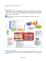
19 Open Rails Software Platform ................................................................................................... 199
20 Plans and Roadmap ................................................................................................................ 202
21 Acknowledgements ................................................................................................................... 203
22 Appendices ............................................................................................................................... 205
1
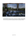
Cover picture by Max Brisben
i
1 Legal
1.1 Warranty
NO WARRANTIES. openrails.org disclaims any warranty, at all, for its Software. The Open Rails
software and any related tools, or documentation is provided “as is” without warranty of any kind,
either express or implied, including suitability for use. You, as the user of this software,
acknowledge the entire risk from its use. See the license for more details.
1.2 Properties Acknowledgment
Open Rails, Open Rails Transport Simulator, ORTS, openrails.org, Open Rails symbol and
associated graphical representations of Open Rails are the property of openrails.org. All other third
party brands, products, service names, trademarks, or registered service marks are the property of
and used to identify the products or services of their respective owners.
1.3 Copyright Acknowledgment and License
©2009-2015 openrails.org
This document is part of Open Rails.
Open Rails is free software: you can redistribute it and/or modify it under the terms of the GNU
General Public License as published by the Free Software Foundation, either version 3 of the
License, or any later version.
You should have received a copy of the GNU General Public License as part of the Open Rails
distribution in Documentation\Copying.txt. If not, see http://www.gnu.org/licenses/.
Page 1 of 206
2 New in This Release
Here are the features which have been added or substantially changed since v0.9 was released.
Extremely high compatibility with MSTS content
Train operation accordingly to timetables in .csv format, entered with a specific editor
Support for languages other than English
Support of 3D cabs
Train physics far more realistic than in MSTS
Some experimental features have been added which you can turn on; some of them may affect
performance:
Compatibility with MSTS environment files
Extended AI train shunting
Adhesion linked to weather
Support for DDS textures
Extended viewing distance
Page 2 of 206
3 Introduction
3.1 What is Open Rails?
Open Rails software (OR) is a community developed and maintained project from openrails.org. Its
objective is to create a new transport simulator platform that is first, compatible with routes,
activities, consists, locomotives, and rolling stock created for Microsoft Train Simulator (MSTS); and
secondly, a platform for future content creation freed of the constraints of MSTS (in this manual
MSTS means MSTS with MSTS Bin extensions, if not explicitly stated in a different way).
Our goal is to enhance the railroad simulation hobby through a community-designed and
supported platform built to serve as a lasting foundation for an accurate and immersive simulation
experience. By making the source code of the platform freely available under the GPL license, we
ensure that OR software will continually evolve to meet the technical, operational, graphical, and
content building needs of the community. Open architecture ensures that our considerable
investment in building accurate representations of routes and rolling stock will not become
obsolete. Access to the source code eliminates the frustration of undocumented behavior and
simplifies understanding the internal operation of the simulator without the time-consuming trial
and error-prone experimentation typically needed today.
Open Rails software is just what the name implies – a railroad simulation platform that’s open for
inspection, open for continuous improvement, open to third parties and commercial enterprises,
open to the community and, best of all, an open door to the future.
3.2 About Open Rails
To take advantage of almost a decade of content developed by the train simulation community,
Open Rails software is an independent game platform that has backward compatibility with MSTS
content. By leveraging the community’s knowledge base on how to develop content for MSTS,
Open Rails software provides a rich environment for both community and payware contributors.
The primary objective of the Open Rails project is to create a railroad simulator that will provide
‘true to life’ operational experience. The Open Rails software is aimed at the serious train
simulation hobbyist; someone who cares about locomotive physics, train handling, signals, AI
behavior, dispatching, and most of all running trains in a realistic, prototypical manner. While the
project team will strive to deliver an unparalleled graphical experience, ‘eye candy’ is not the
primary objective of Open Rails software.
By developing a completely new railroad simulator, Open Rails software offers the potential to
better utilize current and next generation computer resources, like graphics processing units
(GPUs), multi-core CPUs, advanced APIs such as PhysX, and widescreen monitors, among many
others. The software is published so that the user community can understand how the software
functions to facilitate feedback and to improve the capabilities of Open Rails software.
Open Rails is published under the GPL license which is "copyleft"1 to ensure that the source code
always remains publicly available.
1
http://www.gnu.org/copyleft/
Page 3 of 206
3.3 Does Open Rails Need MSTS to Run?
This is not a correctly set question. Open Rails is able to run a vast majority of MSTS content
(routes, trains, activities). Open Rails does not need MSTS executable files (e.g. .exe or .dll files),
neither does it need .ini files.
However, if the MSTS content uses content files originally delivered with MSTS, such as tracks or
general sounds (this applies in particular to routes), obviously to run such content OR needs such
files.
If instead (and there are examples of this) the MSTS content does not use such original content
files, again obviously OR does not need original MSTS files. Read here for further detail.
In both cases, MSTS content files (original and not) must be organized in an MSTS-compatible
folder structure. Such a structure is described here. In this manual such a folder structure will be
called an “MSTS installation” for clarity, even if this wording is not completely correct.
A proof that Open Rails itself does not need an MSTS installation at all to run is e.g. this route.
3.4 Community
At the present time, Open Rails software is offered without technical support. Therefore, users are
encouraged to use their favorite train simulation forums to get support from the community.
Train-Sim.Com
http://forums.flightsim.com/vbts/
UK Train Sim
http://forums.uktrainsim.com/index.php
Elvas Tower
http://www.elvastower.com/forums/index.php?/index
For users interested in multiplayer sessions, a forum is set up for you to seek and announce
hosting sessions: http://www.tsimserver.com.
The Open Rails team is NOT planning on hosting a forum on the Open Rails website. We believe
that the best solution is for the current train simulation forum sites to remain the destination for
users who want to discuss topics relating to Open Rails software. The Open Rails team monitors
and actively participates in these forums.
Page 4 of 206
3.5 Highlights of the Current Version
3.5.1 Focus on Compatibility
With this release the announced goal has been reached to make as much of the existing MSTS
content as possible run in Open Rails. The development team's initial focus has been to provide a
fairly complete visual replacement for MSTS that effectively builds on that content, achieving all
the compatibility that is worthwhile, at the same time delivering a system which is faster and
more robust than MSTS.
3.5.2 Focus on Operations
Release 1.0 clears the way to improving on MSTS in many ways which can be summed up as
moving from Foundation to Realism and eventually to Independence, and already includes
features that are beyond MSTS. Non-player trains can already have a first release movement
orders (i.e. pickups, drop offs) based on files in MSTS format. Deadlocks between player
and non-player trains, that are frequent in MSTS, have been practically eliminated.
3.5.3 Focus on Realistic Content
The physics underlying adhesion, traction, engine components and their performance are based
on a world-class simulation model that takes into account all of the major components of diesel,
electric and steam engines. This includes elements like friction resistance in curves and tunnels, a
very sophisticated steam locomotive physics modeling, many optional curves to define precise
locomotive physics, coupler forces and much more. It is foreseen that beyond release 1.0 Open
Rails will approach the level of physics realism only available in professional simulators.
Existing models that do not have the upgraded Open Rails capabilities continue, of course, to
perform well.
In the package of this version also ancillary programs (“tools”) are delivered, including:
Track Viewer: a complete track viewer and path editor
Activity Editor: a draft new activity editor to move beyond MSTS
Timetable Editor: a tool for preparing Timetables
Page 5 of 206
4 MSTS File Format Compatibility
Open Rails software supports the MSTS file formats detailed below. The software uses a file
parser to read the MSTS file information for use by the Open Rails software. Testing of the parser
software indicates that it will locate many errors or malformation in these files that are not
highlighted by the MSTS train sim software or by other utilities. In most cases, the Open Rails
software will ignore the error in the file and run properly. Open Rails software logs these errors in a
log file on the user’s desktop. This log file may be used to correct problems identified by the Open
Rails software.
4.1 Trainset
The software currently supports Shape (.s), Shape Definition (.sd), Sound (.sms), Cab (.cvf), and
texture Ace (.ace) files; including displaying the correct LOD, alpha and transparency attributes.
Moreover it supports the file types: Engine (.eng); Wagon (.wag). It substitutes MSTS-style physics
to enable the user to operate trains.
4.2 Consists
Open Rails software reads and displays Consist files (.con) used for Player Train, AI Train, and
Loose Consists in activities.
4.3 Services
Open Rails software supports MSTS Service files (.srv) for the creation of both Player and AI
services.
4.4 Paths
Open Rails software supports MSTS Path files (.pat) for determining the path of both Player and AI
Trains.
4.5 Routes
Open Rails software supports the following MSTS Route files with the limitations noted.
Route Database file (.rdb) - CarSpawner is supported.
Reference File (.ref) – Open Rails does not provide a Route Editor in the current
release.
Track Database file (.tdb) – supported
Route File (.trk) – Level Crossings and overhead wires are supported.
Sigcfg (.dat) file – Signal & scripting capabilities are supported.
Sigscr (.dat) file – Signal & scripting capabilities are supported.
Speedpost (.dat) file – Supported
Spotter (.dat) file – Supported
Page 6 of 206
Ssource (.dat) file – Supported
Telepole (.dat) file – Supported
Tsection (.dat) file – Supported
Ttype (.dat) file – Supported
Hazards (.haz) file - Supported
4.6 Environment
Open Rails software does not support advanced water dynamic effects at this time, while it
supports first-level, player-driven dynamic weather effects.
Open Rails provides two types of environment representation that can be selected by the player at
game start: a MSTS compatible one and a native one.
In the native version Open Rails software uses its own sky, cloud, sun, moon and precipitation
effects developed exclusively for it. In activity mode the starting parameters for time of day and
weather are read from the activity file to determine the starting display in Open Rails software.
4.7 Activities
Open Rails software runs without problems a great percentage of the passenger and freight
activities created using the MSTS activity editor. It also offers some OR_specific options to add
interesting features to existing activities.
4.8 OR Folder Structure
Open Rails uses a subset of the MSTS folder structure to run.
The following folders, together with their related sub-folders, are needed at root level:
GLOBAL
ROUTES
TRAINS
SOUND
At root level no files are needed.
Within the GLOBAL folder the following sub-folders are needed if global (shared among more than
one route) shapes and textures are used:
SHAPES
TEXTURES
Within the GLOBAL folder only the file tsection.dat is absolutely needed. Files sigcfg.dat and
sigscr.dat are needed if there are routes that don't have their own specific files with the same
names in their root folder.
Page 7 of 206
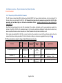
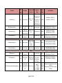
4.9 Which Original MSTS Content Files Are Usually Needed To Run MSTS-Compatible
Content Generated by Third Parties?
A general summary of which original MSTS content files within the Train Simulator root folders are
usually used by MSTS-compatible content follows.
GLOBAL root folder:
Many routes use specific track sets, like XTRACK, UK-finescale etc.
Routes which solely use such sets do not need any of the original MSTS files from GLOBAL,
as all required files come from the relevant track set. There are however also many routes
using original MSTS track sets. These routes will need part or all the files contained in the
SHAPES and TEXTURES subfolders within the GLOBAL folder.
ROUTES root folder:
In principle, to run a route only that specific route folder is required.
However, many routes - in particular freeware routes - use much material from the original
MSTS routes, and therefore the original MSTS routes need to be available in order to
properly install these routes.
TRAINS root folder:
Requirements are similar to routes. Again, only the folders for the trainsets which are actually
used are required, but many third-party trainsets refer to original MSTS files like cabviews
and, in particular, sound files. Many consists refer to engines or wagons from the original
MSTS routes but those can be easily replaced with other engines or wagons.
SOUND root folder:
Only very few routes provide a full new sound set, so the original files included in this folder
are usually needed.
Page 8 of 206
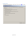
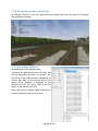
5 Getting Started
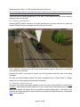
After having successfully installed Open Rails (see the Installation Manual), to run the game you
must double-click on the Open Rails icon on the desktop, or on the OpenRails.exe file.
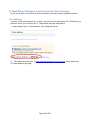
The OpenRails main window will appear. This displays your available MSTS installations.
5.1 Installation Profiles
In the simplest case, where you have only a basic MSTS installation (see paragraph “Does Open
Rails need MSTS to run?” for a precise definition of a MSTS installation) OR should already
correctly point to that. Installation. To check this, you should initially see under “Installation Profile”
the string “ – Default –”.Under “Route” you should see the name of one of the MSTS routes in your
MSTS installation.
You can easily add, remove or move other MSTS installations and select among them (e.g. if you
have any so-called “mini-routes” installed.). Click on the “Options” button and select the “Content”
tab. See the “Content Options” discussed below for more instructions.
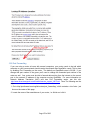
5.2 Updating OR
When a new release of OR is available and your computer is online, a link “Update to xnnnn”
appears in the upper right corner. The string “xnnnn” is the release number of the newest release
that matches your selected level of update. Various level of updates called Update Channels are
available. You may choose the desired level in the “Options-Update” window, described below.
Page 9 of 206
When you click on the update link OR will download and install the new release. In this way your
version of Open Rails is always up to date. Note, however, that previously saved games may not
be compatible with newer versions, as described here.
Clicking the link “What's new?” in the upper centre part of the main menu window will connect to a
website that summarizes the most recent changes to the OR program.
5.3 Preliminary Selections
Firstly, under “Route:” select the route on which you wish to play.
If you check the “Logging” checkbox, Open Rails will generate a log file named OpenRailsLog.txt
that resides on your desktop. This log file is very useful to document and investigate malfunctions.
At every restart of the game (that is after clicking “Start” or “Server” or “Client”) the log file is
cleared and a new one is generated.
If the “Windowed” checkbox is checked, Open Rails will run in a window instead of full screen.
If you wish to fine-tune Open Rails for your system, click on the “Options” button. See the Chapter:
“Open Rails Options” which describes the extensive set of OR options. It is recommended that you
read this chapter.
5.4 Gaming Modes
One of the plus points of Open Rails is the variety of gaming modes you can select.
5.4.1 Traditional “Activity” and “Explore mode” modes
As a default you will find the radio button “Activity” selected in the start window, as above.
This will allow you to run an activity or run in explore mode.
If you select “-Explore Route-” (first entry under “Activity:”), you will also have to select the consist,
the path, the starting time, the season and the weather with the relevant buttons.
To select the consist you have two possibilities: either you click under “Consist:”, and the whole list
of available consists will appear, or you first click under “Locomotive:”, where you can select the
desired locomotive, and then click under “Consist:”, where only the consists led by that locomotive
will appear.
If you instead select a specific activity, you won't have to perform any further selections.
If you have selected the related Experimental Option, at runtime you can switch Autopilot mode on
or off, which allows you to watch OR driving your train, as if you were a trainspotter or a visitor in
the cab.
Page 10 of 206
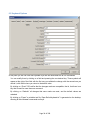
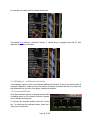
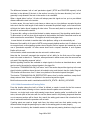
5.4.2 Timetable Mode
If you select the radio button “Timetable”, the main menu window will change as follows:
Timetable mode is unique to Open Rails, and is based on a “timetable” that is created in a
spreadsheet formatted in a predefined way, defining trains and their timetables, their paths, their
consists, some operations to be done at the end of the train run, and some train synchronization
rules.
Timetable mode significantly reduces development time with respect to activities in cases where
no specific shunting or train operation is foreseen. The complete description of the timetable mode
can be found here.
The spreadsheet has a .csv format, but it must be saved in Unicode format with the extension
“.timetable_or” in a subdirectory named “Openrails” that must be created in the route's
ACTIVITIES directory.
For the game player, one of the most interesting features of timetable mode is that any one of the
trains defined in the timetable can be selected as the player train.
The drop-down window “Timetable set:” allows you to select a timetable file from among those
found in the route’s “Activities/Openrails/” folder.
Now you can select in the drop-down window “Train:” from all of the trains of the timetable the train
you desire to run as the Player train. Season and weather can also be selected.
Page 11 of 206
5.4.3 Run!
Now, click on “Start”, and OR will start loading the data needed for your game. When loading
completes you will be within the cab of your locomotive! You can read further in the chapter
“Driving a Train”.
5.4.4 Multiplayer Mode
Open Rails also features this exciting game mode: several players, each one on a different
computer in a local network or through the Internet, can play together, each driving a train and
seeing the trains of the other players, even interacting with them by exchanging wagons, under the
supervision of a player that acts as dispatcher. The multiplayer mode is described in detail here.
5.4.5 Replay
This is not a real gaming mode, but it is nevertheless another way to experience OR. After having
run a game you can save it and replay it: OR will save all the commands that you gave, and will
automatically execute the commands during replay: it's like you are seeing a video on how you
played the game. Replay is described later together with the save and resume functions.
Page 12 of 206
6 Open Rails Options
Clicking on the “Options” button opens a multi-panel window. The Menu > Options panels contain
the settings which remain in effect during your simulation. Most of the options are self-explanatory;
you may set them according to your preference and system configuration. For example, you can
turn off dynamic shadowing if your system has low FPS (frames-per-second) capability. The
options configuration that you select is saved when you click “OK”. When you restart OR, it will
use the last options configuration that you selected.
There are 10 option panels, described below.
6.1 General Options
6.1.1 Alerter in Cab
As in real life, when this option is selected, the player driving the train is required to perform
specific actions to demonstrate that he is “alive”, i.e. press the Alerter Button (or press the Key Z).
As the player may sometimes use a view other than the cabview to follow the train, and therefore
will not see the alerter warning, selecting the related option “Also in external views” enables the
alerter in those views as well.
Page 13 of 206
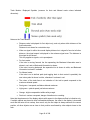
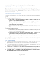
6.1.2 Dispatcher window
It is suggested to always select this option. When this option is selected, pressing Ctrl+9 at
runtime creates an additional window like the following. This window coexists with the main Open
Rails window, and Alt+Tab switches between it and the Open Rails window. See the related option
“Fast full screen Alt+Tab”.
Through this window you can monitor train movements and also influence them, by setting signals
and switches. A complete description of the dispatcher window can be found here.
6.1.3 Graduated release air brakes
Selecting this option allows a partial release of the brakes. Generally speaking, operating with the
option checked is equivalent to passenger standard and unchecked is equivalent to freight
standard. A complete description of this option can be found here .
6.1.4 Large address aware binaries
It is suggested to leave this option checked. When it is unchecked, Open Rails can use a
maximum of 2 GB of RAM. When it is checked, the maximum is 4 GB for 64-bit Windows systems,
and 2 or 3 GB for 32-bit Windows systems. To increase the maximum RAM used by OR in 32-bit
Page 14 of 206
Windows systems from 2 to 3 GB see the information found here:
http://knowledge.autodesk.com/support/autocad/troubleshooting/caas/sfdcarticles/sfdcarticles/How
-to-enable-a-3GB-switch-on-Windows-Vista-Windows-7-or-Windows-XP-s.html .
Take note that the RAM increase from 2 to 3 GB in 32-bit systems can slow down computer
operation when not using OR.
6.1.5 Control confirmations
Following MSTS practice, whenever you make adjustments to the train controls (e.g. open the
throttle) OR briefly shows a message near the bottom of the screen.
This is helpful for operations that don't have visible feedback and also allows you to control the
train without being in the cab.
Uncheck this option if you prefer to monitor your cab instruments and don't want to see these
messages.
OR uses the same message scheme for system messages such as "Game saved" or "Replay
ended" but you cannot suppress these system messages.
6.1.6 Retainer valve on all cars
The player can change the braking capability of all of the cars in the simulation to include Brake
Retainers. These cause the brake cylinder on a car to retain some fixed pressure when the train
brakes are released; this causes the car to produce a constant braking force. If this option is not
checked, then brake retainers are only found on cars that have an appropriate entry, as described
here, in their .wag files.
Page 15 of 206
6.1.7 Brake pipe charging rate
The Brake Pipe Charging Rate (PSI/Second) value controls the charging rate of the main air
brake pipe. Increasing the value will reduce the time required to recharge the train (i.e. when
releasing the brakes after a brake application), while decreasing the value will slow the charging
rate. See also the paragraphs on the OR implementation of the braking system.
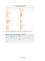
6.1.8 Language
OR is an internationalized package. It supports many languages, and others can be added by
following the instructions contained in the “Localization Manual” which can be found in the Open
Rails Source/Trunk/Documentation folder.
When “System” is selected, OR automatically selects the language of the hosting Windows, if the
language is available.
6.1.9 Pressure unit
The player can select the unit of measure of brake pressure in the HUD display (see here for HUD
information).
When set to “automatic” the unit of measure is the same as that used in the cabview of the
locomotive.
6.1.10 Other units
This selects the units displayed for length, mass, pressure, etc. in the F5 HUD of the simulation.
The option “Player’s Location” sets the units according to the Windows “Language and Region”
settings on the player’s computer.
The option “Route” set the units based on the data in the route files. The other options are selfexplanatory.
The F5 HUD uses the abbreviations “stn” for short tons (2000 lb.) and “t” or “tn” for metric tons
(tonnes).
Note that the units displayed by the F4 Track Monitor (e.g. velocity and distance) are always
based on data read from the route files.
Page 16 of 206
6.2 Audio Options
Except for very slow computers, it is suggested that you leave the “MSTS Bin compatible sound”
option checked and set the Sound detail level to 5.
The “% sound volume” scroll button allows adjustment of the volume of OR sound.
Page 17 of 206
6.3 Video Options
6.3.1 Dynamic shadows
With this option it is possible to enable or disable the display of dynamic shadows. Disabling can
be helpful if low frame rates are experienced.
6.3.2 Fast full-screen alt+tab
When this option is selected, and OR is running full-screen, pressing Alt+Tab leaves OR fullscreen and running, and allows the Dispatcher Window to be shown in front of it. If this option is
not selected, OR is minimized. The Dispatcher Window option must also be selected and the
Dispatcher Window started with Ctrl+9 to display the Dispatcher Window. Each successive press
of Alt+Tab will toggle between the Dispatcher window and the OR window
6.3.3 Glass on in-game windows
When this option is checked, the in-game windows are displayed in a semitransparent mode.
6.3.4 Model instancing
When the option is checked, in cases where multiple instances of the same object have to be
drawn, only a single draw call is sent to the GPU. This means lower CPU load. It is suggested to
always check this option.
Page 18 of 206
6.3.5 Overhead wire
This option will enable or disable display of the overhead wire.
6.3.6 Vertical sync
When this option is selected, the OR update rate cannot be higher than the monitor vertical sync
frequency (typically 60 Hz). This reduces CPU energy consumption in fast PCs.
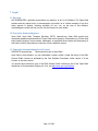
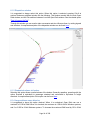
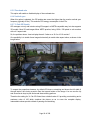
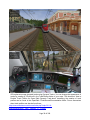
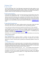
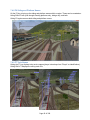
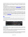
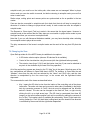
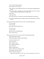
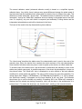
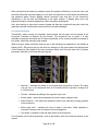
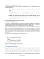
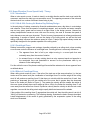
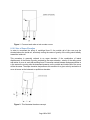
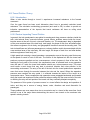
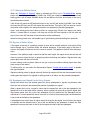
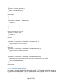
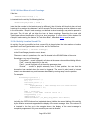
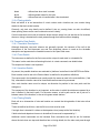
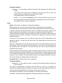
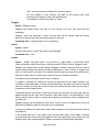
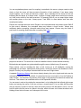
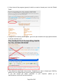
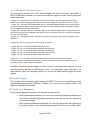
6.3.7 % Cab 2D Stretch
OR manages not only cab interiors using 2D images in a MSTS-compatible way, but also supports
3D models. Most 2D cab images follow MSTS practice, being 1024 x 768 pixels to suit monitors
with a 4:3 aspect ratio.
So, the problem arises - how to display these 4:3 cabs on a 16:9 or 16:10 monitor?
One possibility is to stretch these images horizontally to match other aspect ratios, as shown in the
image below.
To respect the proportions however, by default OR does no stretching and shows the full width of
the cab interior, thus losing a portion from the top and bottom of the image. You can use the Up
and Down Arrow keys to pan and reveal these missing portions.
Therefore the setting for % Cab 2D Stretch has a default value of 0 providing no stretching and a
maximum value of 100 which stretches the picture so as to cover the complete display.
Intermediate values provide a blend of panning and stretching.
Page 19 of 206
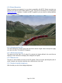
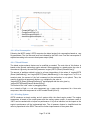
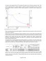
6.3.8 Viewing distance
This option defines the maximum distance at which terrain is displayed. At higher distances
Distant Mountains will be displayed (see below). This parameter increases CPU and GPU load.
Also, some routes are optimized for the standard MSTS maximum viewing distance (2000m).
Page 20 of 206
6.3.9 Distant Mountains
Distant mountains are supported in a way that is compatible with MSTS. Distant mountains are
present in the route if it has a folder called LO_TILE. You may turn the feature on by checking the
“Distant Mountains” checkbox. In addition to MSTS capability, you can select the viewing distance
of the distant mountains.
6.3.10 Viewing vertical FOV
This value defines the vertical angle of the world that is shown. Higher values correspond roughly
to a zoom out effect. The default is 45 degrees.
6.3.11 World object density
This value can be set from 0 to 10; when 10 is selected, all objects defined in the route files are
displayed. Lower values do not display some categories of objects.
6.3.12 Window size
This pair of values defines the size of the OR window. There are some preconfigured pairs of
values, however you may also manually enter a different size to be used.
6.3.13 Ambient daylight brightness
With this slider you can set the daylight brightness.
Page 21 of 206
6.4 Simulation Options
The majority of these options define train physics behavior.
6.4.1 Advanced adhesion model
OR supports two adhesion models: the basic one is similar to the one used by MSTS, while the
advanced one is based on a model more similar to reality.
For more information read the section on “Adhesion Models” later in this manual.
6.4.2 Adhesion moving average filter size
The computations related to adhesion are passed through a moving average filter. Higher values
cause smoother operation, but also less responsiveness. 10 is the default filter size.
6.4.3 Break couplers
When this option is selected, if the force on a coupler is higher than the threshold set in the .eng
file, the coupler breaks and the train is divided into two parts.
Page 22 of 206
6.4.4 Curve dependent resistance
When this option is selected, resistance to train motion is influenced by the radius of the curve on
which the train is running. This option is described in detail here (theory) and also here (OR
application).
6.4.5 Curve dependent speed limit
When this option is selected, OR computes whether the train is running too fast on curves, and if
so a warning message is logged and displayed on the monitor. This option is described in detail
here (theory) and also here (OR application).
6.4.6 Tunnel dependent resistance
When this option is selected, OR takes into account the fact that trains in tunnels are subject to
higher air resistance, and therefore need a higher effort at invariant speed. This option is
described in detail here (theory) and here (OR application).
6.4.7 Override non-electrified route line-voltage
This option allows running (in a non-prototypical way) electric locomotives on non-electrified
routes.
6.4.8 Steam locomotive hot start
This option allows starting the game with the boiler water temperature already at a value that
allows running the locomotive. If the option is not selected, you will have to wait until the water
temperature reaches a high enough value.
Page 23 of 206
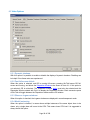
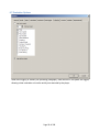
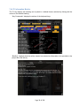
6.5 Keyboard Options
In this panel you will find listed the keyboard keys that are associated with all OR commands.
You can modify them by clicking on a field and pressing the new desired key. Three symbols will
appear at the right of the field: with the first one you validate the change, with the second one you
cancel it, with the third one you return to the default value.
By clicking on “Check” OR verifies that the changes made are compatible, that is, that there is no
key that is used for more than one command.
By clicking on “Defaults” all changes that were made are reset, and the default values are
reloaded.
By clicking on “Export” a printable text file “Open Rails Keyboard.txt” is generated on the desktop,
showing all links between commands and keys.
Page 24 of 206
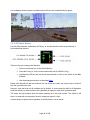
6.6 Data Logger Options
By selecting the option “Start logging with the simulation start” or by pressing F12 a file with the
name dump.csv is generated in the configured Open Rails logging folder (placed on the Desktop
by default). This file can be used for later analysis.
Page 25 of 206
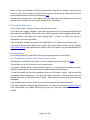
6.7 Evaluation Options
When data logging is started (see preceding paragraph), data selected in this panel are logged,
allowing a later evaluation on how the activity was executed by the player.
Page 26 of 206
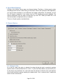
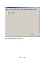
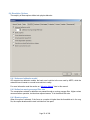
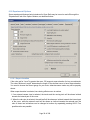
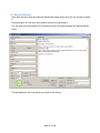
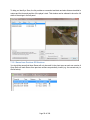
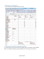
6.8 Content Options
This window allows you to add, remove or modify access to additional MSTS installations or
miniroute installations for Open Rails. Installations located on other drives, or on a USB key, can
be added even if they are not always available.
Click on the “Add” button, and locate the desired installation. OR will automatically enter a
proposed name in the “Name:” window that will appear in the “Installation set:” window on the
main menu form. Modify the name if desired, then Click “Save” to add the new path and name to
Open Rails. Then click “OK” to return to Open Rails.
To remove an entry (note that this does not remove the installation itself!) select the entry in the
window, and click “Delete”, then “OK” to close the window. To modify an entry, use the “Browse…”
button to access the location; make the necessary changes, and then “Save” the changes.
Page 27 of 206
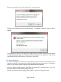
6.9 Updater Options
These options control which OR version update channel is active (see also here). The various
options available are self-explanatory.
Page 28 of 206
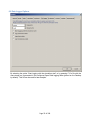
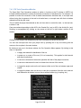
6.10 Experimental Options
Some experimental features being introduced in Open Rails may be turned on and off through the
“Experimental” tab of the Options window, as described below:
6.10.1 Super-elevation
If the value set for “Level” is greater than zero, OR supports super elevation for long curved tracks.
The value “Minimum Length” determines the length of the shortest curve to have super-elevation.
You need to choose the correct gauge for your route, otherwise some tracks may not be properly
shown.
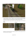
When super-elevation is selected, two viewing effects occur at runtime:
1. If an external camera view is selected, the tracks and the running train will be shown inclined
towards the internal part of the curve.
2. When the cab view is selected, the cab itself will be shown as inclined towards the internal part
of the curve, while the external world will be shown as inclined towards the external part; the
ratio of these two inclinations can be changed at runtime by repeatedly pressing Alt+R. Four
possible ratios are possible.
Page 29 of 206
OR implements super elevated tracks using Dynamic Tracks. You can change the appearance of
tracks by creating a TrProfile.sft in the TrackProfiles folder of your route. The document “How to
Provide Track Profiles for Open Rails Dynamic Track.docm” describing the creation of track
profiles can be found in the OpenRails /Trunk/Source/Documentation folder. Forum discussions
about track profiles can also be found here:
http://www.elvastower.com/forums/index.php?/topic/21119superelevation/page__view__findpost__p__115247.
Page 30 of 206
6.10.2 Automatically tune settings to keep performance level
When this option is selected OR attempts to maintain the selected Target frame rate FPS
( Frames per second). To do this it decreases or increases the viewing distance of the standard
terrain. If the option is selected, also select the desired FPS in the “Target frame rate” window.
6.10.3 Double overhead wires
MSTS uses a single wire for electrified routes; you may check this box so that OR will show the
two overhead wires that are more common.
6.10.4 Show shape warnings
When this option is selected, when OR is loading the shape (.s) files it will report errors in syntax
and structure (even if these don't cause runtime errors) in the Log file “OpenRailsLogFile.txt” on
the desktop.
6.10.5 Forced red at station stops
In case a signal is present beyond a station platform and in the same track section (no switches in
between), OR will set the signal to red until the train has stopped and then hold it as red from that
time up to two minutes before starting time. This is useful in organizing train meets and takeovers,
however it does not always correspond to reality nor to MSTS operation. So with this option the
player can decide which behavior the start signal will have. This option is checked by default.
Unchecking the option has an effect on simulation behavior only if no Timetable mode operation is
under way.
6.10.6 Load night textures only when needed
As a default OR loads night textures together with the day textures at daytime. When this option is
selected, to reduce loading time and reduce memory used, night textures are not loaded in the
daytime and are only loaded at sunset (if the game continues through sunset time).
6.10.7 Signal light glow
When this option is set, a glowing effect is added to signal semaphores when seen at distance, so
that they are visible at a greater distance. There are routes where this effect has already been
natively introduced; for these, this option is not recommended.
6.10.8 Extended AI train shunting
When this option is selected, further AI train shunting functions are available. This allows for more
interesting and varied activities. If an activity is run which makes use of these function, this option
must be selected. This option has no effect in Timetable mode.
The following additional shunting functions are available:
AI train couples to static consist and restarts with it.
AI train couples to player or AI train and becomes part of it; coupled AI train continues
on its path.
AI train couples to player or AI train and leaves to it its cars; coupled and coupling
train continue on their path.
AI train couples to player or AI train and “steals” its cars; coupled and coupling train
continue on their path.
Page 31 of 206
AI train uncouples any number of its cars; the uncoupled part becomes a static
consist. With the same function it is possible to couple any number of cars from a
static consist.
for content developers: A more detailed description of this feature can be found under Extended AI
Train Shunting under Open Rails Train Operation.
for content developers: Selecting this option also enables the waiting points to declare an absolute
time-of-day instead of a waiting point duration. A more detailed description of this feature can be
found in the related paragraph in the chapter “Open Rails Train Operation”.
6.10.9 Autopilot
With this option enabled and when in activity mode, it is possible to stay in the cab of the player
train, but to let Open Rails move the train, respecting path, signals, speeds and station stops.
It is possible to switch the player train between autopilot mode and player driven mode at run time.
The Autopilot mode is described here.
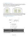
6.10.10 ETCS circular speed gauge
When this option is selected, it is possible to add to the cabview a circular speed gauge
accordingly to the European standard train control system ETCS.
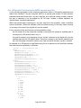
For content developers: The gauge is added by the insertion of a block like the following into the .cvf
file:
Digital (
Type ( SPEEDOMETER DIGITAL )
Style ( NEEDLE )
Position ( 160 255 56 56 )
ScaleRange ( 0 250 )
Units ( KM_PER_HOUR )
)
6.10.11 Extend object maximum viewing distance to horizon
With this option selected, all objects viewable up to the viewing distance defined in the Video
Options are displayed. As a default ORTS only displays objects up to 2000 m. distance. Selecting
this option improves display quality but may reduce frame rate.
6.10.12 Load DDS textures in preference to ACE
Open Rails is capable of loading both ACE and DDS textures. If only one of the two is present, it is
loaded. If both are present, the ACE texture is loaded unless this option has been selected.
Page 32 of 206
6.10.13 Location-linked passing path processing
When this option is NOT selected, ORTS acts similarly to MSTS. That is, if two trains meet whose
paths share some track section in a station, but are both provided with passing paths as defined
with the MSTS Activity Editor, one of them will run through the passing path, therefore allowing the
meet. Passing paths in this case are only available to the trains whose path has passing paths.
When this option is selected, ORTS makes available to all trains the main and the passing path of
the player train. Moreover, it takes into account the train length in selecting which path to assign to
a train in case of a meet.
for content developers: A more detailed description of this feature can be found under LocationLinked Passing Path Processing in the chapter “Open Rails Train Operation”.
6.10.14 MSTS Environments
By default ORTS uses its own environment files and algorithms, e.g. for night sky and for clouds.
With this option selected, ORTS applies the MSTS environment files. This includes support of
Kosmos environments, even if the final effect may be different from the current MSTS one.
6.10.15 Adhesion factor correction
The adhesion is multiplied by this percentage factor. Therefore lower values of the slider reduce
adhesion and cause more frequent wheel slips and therefore a more difficult, but more challenging
driving experience.
6.10.16 Level of detail bias
This option is an expansion (and replacement) of an earlier experimental option: "Always use
highest level of detail". The new option allows you to increase or reduce the level of detail
generally shown independently of the viewing distance and world object density.
6.10.17 Adhesion proportional to rain/snow/fog
When this option is selected, adhesion becomes dependent on the intensity of rain and snow and
the density of fog. Intensities and density can be modified at runtime by the player.
6.10.18 Adhesion factor random change
This factor randomizes the adhesion factor corrector by the entered percentage. The higher the
value, the higher the adhesion variations.
Page 33 of 206
7 Driving a Train
7.1 Game Loading
Once you have pressed “Start”, Open Rails loads and processes all the data needed to run the
game. During this phase, the route’s splash screen is shown. If the same session was loaded
previously, a bar showing loading progress is shown at the bottom of the display. During loading, if
logging is selected, the log file OpenRailsLog.txt will already begin storing data.
7.2 Entering the Simulation
At the end of the loading phase, you are in the cab of the train you will drive.(Note: some newer
locomotives have experimental 3D cabs - if no cab interior display appears, then type Alt+1 to
display the cab interior.) Depending on the configuration of the activity (in case of activity mode),
your train will be in motion or stopped. In this second case, if the train is driven by an electric
locomotive, as the first operation you have to raise the pantograph (key P). To look around in the
simulation, you can select different views using the keyboard, as described in “Changing the View”
below.
7.3 Open Rails Driving Controls
Open Rails follows MSTS very closely, providing controls to drive steam, electric and diesel
locomotives, both on their own or working together, but also offers additional capabilities.
A very wide range of systems and instruments specified in the ENG and CVF files is supported.
To control the train, you have at your disposal a set of keyboard commands that is equivalent to
those of MSTS, plus some new ones. You can get a printable version of the command set as
described in paragraph 6.5 (Keyboard options), or you can press F1 to immediately get the
scrollable F1 Information Window as shown and described below.
Alternatively, you can operate the cabview controls by mouse click (buttons) and mouse drag
(levers and rotary switches).
7.3.1 Throttle Control
Steam locomotives have a continuous throttle or regulator, but many diesel and electric
locomotives have a notched throttle which moves only in steps. To avoid jerks, some of these
steps may be "smooth", where the power is gradually and automatically adjusted to achieve the
setting.
7.3.2 Dynamic Braking
Dynamic braking is the use of the traction motors of a locomotive (electric or diesel-electric) as
generators to slow the train. Initially, dynamic braking was applied in mountainous territory where
conventional freight-car brakes were prone to overheating on long downgrades. It was also limited
to speeds above 10mph. Dynamic braking controls are usually notched.
In OR, the dynamic brake (controlled by the keys , and . ) is not available unless the throttle is
fully closed; similarly the throttle is not available unless the dynamic brake is fully released (off).
As defined in the CVF file, the tractive and braking forces may be shown on two different
instruments, on one instrument with two needles or on a single instrument where the braking is
shown as a negative value.
Page 34 of 206
7.3.3 Combined Control
Some locomotives are fitted with a "combined control" where a single lever is used to provide
throttle and brake control together, with negative throttle positions used to apply the brake. The
brake element may be either dynamic or conventional train brakes.
There may be a delay changing between throttle and brake operation, representing the time
required to change the operation of the traction motors from motors to generators.
7.3.4 Refill
Diesel and steam locomotives must refill their supplies of fuel occasionally, perhaps daily, but
steam locomotives need water more frequently and have a range of little more than 100 miles.
Use the "T" key to refill with fuel or water.
If the locomotive or tender is alongside the pickup point, e.g. a water tank, then the refilling takes
place as the key is held down. If the locomotive is further away, then the distance to the nearest
pickup is given instead.
7.3.5 Specific Features to Optimize Locomotive Driving
You are encouraged to read the chapter on Open Rails Physics to optimize your driving
capabilities and to achieve a realistic feeling of what happens in a real moving train.
7.3.6 Examples of Driving Controls
for content developers:
For continuous throttle, see MSTS model ...\TRAINS\TRAINSET\ACELA\acela.eng
For a notched non-smooth throttle, see ...\TRAINS\TRAINSET\GP38\gp38.eng
For a combined throttle and dynamic brake, see ...\TRAINS\TRAINSET\DASH9\dash9.eng
For a combined throttle and train brake, see
...\MSTS\TRAINS\TRAINSET\SERIES7000\series7000.eng
Page 35 of 206
7.4 Driving aids
Open Rails provides a large number of driving aids, which support the player during train
operation.
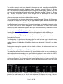
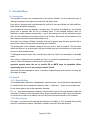
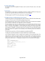
7.4.1 Basic Head Up Display (HUD)
By pressing F5 you get some important data displayed at the top left of the display in the so-called
Head Up Display (HUD). If you want the HUD to disappear, press F5 again.
The HUD has 6 different pages. The basic page is shown at game start. To sequentially switch to
the other pages press Shift+F5. After having cycled through all of the extended HUD pages, the
basic page is displayed again.
To hide or redisplay the current extended HUD data while continuing to show the basic HUD,
press Alt+F5.
The basic page shows fundamental information. The other pages go into more detail, and are
used mainly for debugging or to get deeper information on how OR behaves. They are listed in the
“Analysis tools” subchapter.
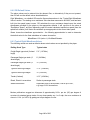
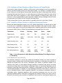
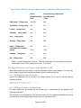
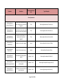
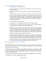
The following information is displayed in the basic display:
Version = The version of the Open Rails software you are running
Time = Game time of the Activity
Speed = the speed in Miles/Hr. or Kilometers/Hr.
Gradient = Route gradient in % in that point
Direction = Position of the Reverser - Electric, Diesel and Steam.
Throttle = Displays the current position of the throttle, expressed as a percentage of
full throttle. Throttle correctly uses Notches and configured % of power for Diesel
engines or % of throttle for steam engines.
Train Brake = Shows the current position of the train brake system and the pressure
value of the train brakes. Braking correctly reflects the braking system used;
hold/release, self- lapping or graduated release. The Train brake HUD line has two
Brake Reservoir pressure numbers: the first is the Equalization Reservoir (EQ) and
the second is the Brake Cylinder (BC) pressure. The two BP numbers report the brake
pressure in the lead engine and in the last car of the train. The unit of measure used
for brake pressure is defined by the option “Pressure unit”.
Engine Brake = percentage of independent engine brake. Not fully releasing the
engine brake will affect train brake pressures.
Dynamic brake = if engaged, shows % of dynamic brake
Engine = shows the running status of the engine.
In case of a gear-based engine, after the “Engine” line a “Gear” line appears
displaying the actual gear. N means no gear inserted.
FPS = Number of Frames rendered per second
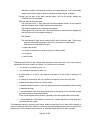
Page 36 of 206
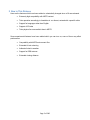
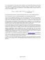
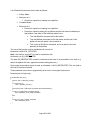
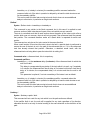
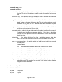
If the Autopilot is active, an additional line will be shown.
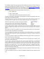
An example of the basic HUD for Diesel locomotives:
7.4.2 Electric Locomotives – Additional information
For electric locomotives information about the pantograph state is also shown and whether the
locomotive has power (at least one pantograph raised) or not.
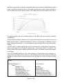
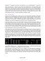
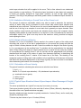
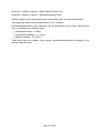
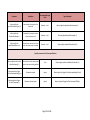
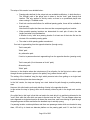
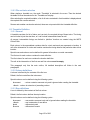
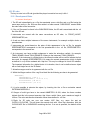
7.4.3 Steam Engine – Additional Information
When using a steam engine the following additional information is displayed in the HUD:
Steam Usage in lbs. /h, based on entirely new physics code developed by the Open
Rails team. It is calculated by parsing the .eng file for the following parameters:
number of cylinders; cylinder stroke; cylinder diameter; boiler volume; maximum boiler
pressure; maximum boiler output; exhaust limit; and basic steam usage.
Boiler pressure.
Water level.
Levels of coal and water in %.
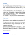
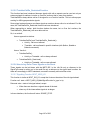
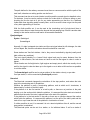
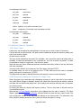
Page 37 of 206
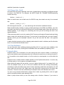
An example of the basic HUD for Steam locomotives:
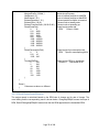
The default firing setting is automatic fireman. If manual firing is engaged (with Ctlr+F), then
additional information is included:
7.4.4 Multiplayer – Additional Information
If a multiplayer session is active, the following additional information is shown: the actual status of
the player (dispatcher, helper or client), the number of players connected and the list of trains with
their distances from the train of the player viewing the computer.
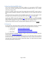
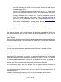
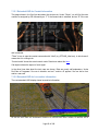
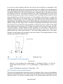
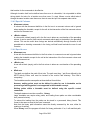
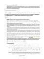
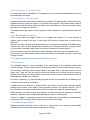
7.4.5 Compass Window
Open Rails software displays a compass that provides
a heading based on the camera’s direction together
with its latitude and longitude.
To activate the compass window press the 0 (zero)
key. To deactivate the compass window, press the 0
(zero) key a second time.
Page 38 of 206
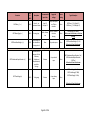
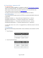
7.4.6 F1 Information Monitor
The F1 key displays the following set of panels in a tabbed format, selected by clicking with the
mouse on the desired heading:
“Key Commands”: displays the actions of the keyboard keys
“Briefing”: displays what the activity creator has entered as information to be provided to the
player about the activity:
Page 39 of 206
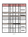
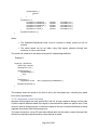
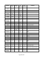
“Timetable”: shows the list of the station stops, if any, with scheduled and actual times of
arrival and departure. During the activity the actual performance will be shown on the F10
Activity Monitor.
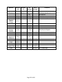
“Work Orders”: if defined by the activity creator, lists the coupling and uncoupling operations
to be performed. When an operation has been completed, the string “Done” appears in the
last column:
“Procedures”: basic instructions for driving trains in Open Rails.
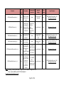
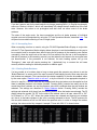
7.4.7 F4 Track Monitor
This window, which is displayed by pressing F4, has two different layouts according the the train’s
control mode: “Auto Signal” mode, “Manual” mode or “Explorer” mode (it is strongly suggested to
follow the link and read the related paragraph).
Auto Signal or Auto mode is the default mode when running activities or timetables.
There are however two main cases where you must switch to “Manual” mode by pressing Ctrl+M:
when the activity requires shunting without a predefined path
when the train runs out of control due to SPAD (“Signal Passed At Danger” or passing
a red signal) or exits the predefined path by error. If such situations occur you will
usually get an emergency stop. To reset the emergency stop and then move to
correct the error, you must first switch to Manual mode.
To switch to manual mode press Ctrl+M when the train is stopped.
You can return to auto mode by pressing Ctrl+M again when the head of the train is again on the
correct path, with no SPAD situation. In standard situations you can also return to auto mode while
the train is moving. Details are described in the paragraph of the link shown above.
Page 40 of 206
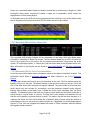
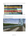
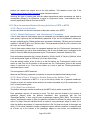
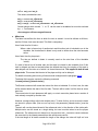
Track Monitor display in Auto Signal mode:
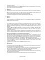
Track Monitor display in Manual mode / Explorer mode:
Page 41 of 206
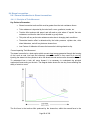
Track Monitor: Displayed Symbols (common for Auto and Manual mode unless indicated
otherwise) :
Notes on the Track Monitor:
Distance value is displayed for first object only, and only when within distance of the
first fixed marker.
Distance is not shown for next station stop.
When no signal is within the normal display distance but a signal is found at a further
distance, the signal aspect is displayed in the advance signal area. The distance to
this signal is also shown.
This only applies to signals, not to speedposts.
For Auto mode :
if the train is moving forward, the line separating the Backward information area is
shown in red, and no Backward information is shown.
If the train is moving backward, the separation line is shown in white, and Backward
information is shown if available.
For Manual mode :
if the train is on its defined path (and toggling back to Auto control is possible), the
own train symbol is shown in white, otherwise it is shown in red.
The colour of the track-lines is an indication of the train’s speed compared to the
maximum allowed speed :
Dark green : low speed, well below allowed maximum
Light green : optimal speed, just below maximum
Orange : slight overspeed but within safety margin
Dark red : serious overspeed, danger of derailment or crashing
Note that the placement of the display objects with respect to the distance offset is indicative only.
If multiple objects are placed at short intermediate distances, the offset in the display is increased
such that the texts do not overlap. As a result, only the first object is always shown at the correct
position, all other objects are as close to their position as allowed by other objects closer to the
train.
Page 42 of 206
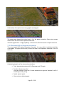
7.4.8 F6 Siding and Platform Names
Hit the F6 key to bring up the siding and platform names within a region. These can be crowded so
hitting Shift+F6 will cycle through showing platforms only, sidings only, and both.
Hitting F6 again removes both siding and platform names.
7.4.9 F7 Train Names
Hitting the F7 key displays train service names (player train always has “Player” as identification).
Hitting Shift+F7 displays the rolling stock IDs.
Page 43 of 206
In a multiplayer session, player-controlled trains will have the id specified by the player:
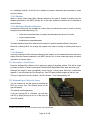
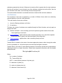
7.4.10 F8 Switch Monitor
Use the Switch Monitor, enabled by the F8 key, to see the direction of the turnout directly in
front and behind the train.
There are 4 ways to change the direction:
Click on the turnout icon in the Switch Monitor;
Press the G key (or, for the turnout behind the train, the Shift+G key);
Hold down the Alt key and use the left mouse button to click on the switch in the Main
Window;
Use the dispatcher window, as described here.
Please note that with the last two methods you can throw any switch, not only the one in front but
also the one behind the train.
However, note also that not all switches can be thrown: in some cases the built-in AI dispatcher
holds the switch in a state to allow trains (especially AI trains) to follow their predefined path.
The arrow and eye symbols have the same meaning as in the track monitor. The switch is red
when it is reserved or occupied by the train, and green when it is free.
A switch shown in green can be operated, a switch shown in red is locked.
Page 44 of 206
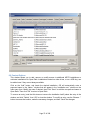
7.4.11 F9 Train Operations Monitor
The Open Rails Train Operations window is similar in function to the F9 window in MSTS, but
includes additional features to control the air brake connections of individual cars. For example, it is
possible to control the connection of the air brake hoses between individual cars, to uncouple cars
without losing the air pressure in the train’s air brake hose, or uncouple cars with their air brakes
released so that they will coast.
The unit which the player has selected as the unit from which to control the train, i.e. the lead unit,
is shown in red.
Cars are numbered according to their UiD in the Consist file (.con) or UiD in the Activity file (.act).
Scrolling is accomplished by clicking on the arrows at the left or right bottom corners of the
window.
Clicking on the coupler icon between any two cars uncouples the consist at that point.
You can also uncouple cars from your player train by pressing the U key and clicking with the
mouse on the couplers in the main window.
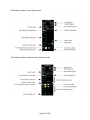
By clicking on any car in the above window, the Car Operation Menu appears. By clicking in this
menu it is possible:
to apply and release the handbrake of the car;
to power on or power off the car (if it is a locomotive). This applies for both electric
and diesel locomotives;
to connect or disconnect locomotive operation with that of the player locomotive;
to connect or disconnect the car’s air hoses from the rest of the consist;
to toggle the angle cocks on the air hoses at either end of the car between open and
closed;
to toggle the bleed valve on the car to vent the air pressure from the car’s reservoir
and release the air brakes to move the car without brakes (e.g. humping, etc.).
Page 45 of 206
By toggling the angle cocks on individual cars it is possible to close selected angle cocks of the air
hoses so that when the cars are uncoupled, the air pressure in the remaining consist (and
optionally in the uncoupled consist) is maintained. The remaining consist will then not go into
“Emergency” state.
When working with cars in a switch yard, cars can be coupled, moved and uncoupled without
connecting them to the train’s air braking system (see the F5 HUD for Braking). Braking must then
be provided by the locomotive’s independent brakes. A car or group of cars can be uncoupled with
air brakes active so that they can be recoupled after a short time without recharging the entire
brake line (“Bottling the Air”). To do this, close the angle cocks on both ends of the car or group
before uncoupling. Cars uncoupled while the consist is moving, that have had their air pressure
reduced to zero before uncoupling, will coast freely.
In Open Rails, opening the bleed valve on a car or group of cars performs two functions: it vents
the air pressure from the brake system of the selected cars, and also bypasses the air system
around the cars if they are not at the end of the consist so that the rest of the consist remains
connected to the main system. In real systems the bypass action is performed by a separate valve
in each car. In the F5 HUD Braking display, the text “Bleed” appears on the car’s display line until
the air pressure has fallen to zero.
More information about manipulating the brakes during coupling and uncoupling can also be found
here.
7.4.12 F10 Activity Monitor
The Activity Monitor is similar in function to MSTS. It records the required “Arrival” time of your train
and the actual arrival time as well as the required “Depart” time and the actual departure time.
A text message alerts the engineer as to the proper departure time along with a whistle or other
departure sound.
7.4.13 Odometer
The odometer display appears in the centre of the main window, toggled on or off by the keys
Shift+Z. The direction of the count is toggled by the keys Shift+Ctrl+Z, and the odometer is reset
or initialized by Ctrl+Z.
When set for counting down, it initializes to the total length of the train. As the train moves, the
odometer counts down, reaching zero when the train has moved its length. When set for counting
up, it resets to zero, and measures the train’s total movement.
For example, if the odometer is set for counting down and you click Ctrl+Z as the front of the train
passes a location, then when it reaches zero you will know, without switching views, that the other
end of the train has just reached the same point, e.g. the entrance to a siding, etc.
Page 46 of 206
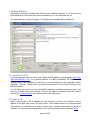
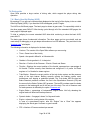
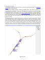
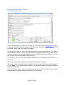
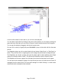
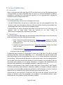
7.5 Dispatcher Window
The dispatcher window is a very useful tool to monitor and control train operation. The Dispatcher
window option must be selected.
The dispatcher window is actually created by pressing Ctrl+9. The window is created in a
minimized state, so to display it in front of the OR window you must click on “Alt+Tab” and select
the dispatcher window icon, or click on one of the OR icons in the taskbar. If you are running OR
in full-screen mode, you must also have the “Fast full screen Alt+Tab” option selected to have both
the OR and the dispatcher windows displayed at the same time. After the dispatcher window has
been selected with Alt+Tab, successive Alt_Tabs will toggle between the OR window and the
dispatcher window.
The dispatcher window is resizable and can also be maximized, e.g. on a second display. You can
define the level of zoom either by changing the value within the “Res” box or by using the mouse
wheel. You can pan through the route by moving the mouse while pressing the left button. You
can hold the shift key while clicking the mouse in a place in the map; this will quickly zoom in with
that place in focus. You can hold Ctrl while clicking the mouse in a place in the map, which will
zoom out to show the whole route. Holding Alt and clicking will zoom out to show part of the route.
Page 47 of 206
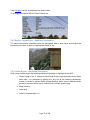
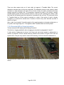
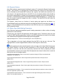
The dispatcher window shows the route layout and monitors the movement of all trains. While the
player train is identified by the “PLAYER” string (or by a “0” if autopilot mode is enabled), AI- trains
are identified by their OR number (that is also shown in the “Extended HUD for Dispatcher
Information”), followed by the service name. Static consists are identified as in MSTS.
The state of the signals is shown (only three states are drawn, that is
Stop – drawn in red
Clear_2 -drawn in green
while all signals with restricting aspect are drawn in yellow.
The state of the switches is also shown. A switch shown with a black dot indicates the main route,
while a grey dot indicates a side route.
When the “Draw path” is checked, the first part of the path that the train will follow is drawn in red.
If a trailing switch in the path is not in the correct position for the path, a red X is shown on it.
When left- or right-clicking on a signal, a pop-up menu appears:
Using the mouse, you can force the signal to Stop, Approach
or Proceed. Later you can return it to System Controlled mode.
By left- or right-clicking on a switch, a small pop-up menu with the two selections “Main route” and
“Side route” appears. By clicking on them you can throw the switch, provided the OR AI dispatcher
allows it.
With respect to AI trains, as a general rule you can command their signals but not their switches,
because AI trains are not allowed to exit their path.
The two checkboxes “Pick Signals” and “Pick Switches” are checked as default. You can uncheck
one of them when a signal and a switch are superimposed in a way that it is difficult to select the
desired item.
You can click a switch (or signal) in the dispatcher window and press Ctrl+Alt+G to jump to that
switch with the free-roam (8-key) camera.
If you click on “View Self” the dispatcher window will center on the player train. However, if the
train moves, centering will be lost.
You can select a train by left-clicking with the mouse its green reproduction in the dispatcher
window, approximately half way between the train's head and its name string. The train body
becomes red. Then if you click on the button “See in game” the main Open Rails window will show
this train in the views for the 2, 3, 4 or 6 keys, (and the 5-key view if available for this train).
Display of the new train may require some time for OR to compute the new image if the train is far
away from the previous camera view.
Take into account that continuous switching from train to train, especially if the trains are far away,
can lead to memory overflows.
If after a train selection you click on “Follow” the dispatcher window will remain centered on that
train.
Page 48 of 206
7.6 Additional Train Operation Commands
OR supports an interesting range of additional train operation commands. Some significant ones
are described here below.
7.6.1 Diesel Power On/Off
With the key Y the player diesel engine is alternatively powered on or off. At game start the engine
is powered on.
With the keys Shift+Y the helper diesel locomotives are alternatively powered on or off. At game
start the engines are powered on.
Note that by using the Car Operation Menu you can also power on or off the helper locomotives
individually.
7.6.2 Initialize Brakes
Entering this command fully releases the train brakes. Usually the train must be fully stopped for
this to be allowed. This action is usually not prototypical. Check the keyboard assignment for the
keys to be pressed. The command can be useful in three cases:
1. A good number of locomotives do not have correct values for some brake parameters in the
.eng file; MSTS ignores these; however OR uses all these parameters, and it may not allow the
brakes to release fully. Of course, it would be more advisable to correct these parameters.
2. It may happen that the player does not want to wait for the time needed to recharge the brakes;
however the use of the command in this case is not prototypical of course.
3. The player may wish to immediately connect brake lines and recharge brakes after a coupling
operation; again, the use of the command is not prototypical.
7.6.3 Connect/Disconnect Brake Hoses
This command should be used after coupling or decoupling. As the code used depends on
keyboard layout, check the keys to be pressed as described in paragraph 6.5 or by pressing F1 at
runtime.
More information on connecting brakes and manipulating the brake hose connections can be
found here and here.
7.6.4 Doors and Mirror Commands
Note that the standard keys in OR for these commands are different from those of MSTS.
7.6.5 Wheelslip Reset
With the keys Ctrl+X you get an immediate wheelslip reset.
7.6.6 Toggle Advanced Adhesion
Advanced adhesion can be enabled or disabled by pressing Ctrl+Alt+X.
7.6.7 Request to Clear Signal
When the player train has a red signal in front or behind it, it is sometimes necessary to ask for
authorization to pass the signal. This can be done by pressing Tab for a signal in front and
Shift+Tab for a signal behind. You will receive a voice message reporting if you received
authorization or not. On the Track monitor window the signal colours will change from red to
Page 49 of 206
red/white if permission is granted.
7.6.8 Change Cab - Ctrl+E
All locomotives and some passenger cars have a forward-facing cab which is configured through
an entry in the ENG file. For example, the MSTS Dash9 file TRAINSET\DASH9\dash9.eng
contains the entry:
CabView ( dash9.cvf )
Where a vehicle has a cab at both ends, the ENG file may also contain an entry for a reversed
cab:
CabView ( dash9_rv.cvf )
OR will recognise the suffix _rv as a rear-facing cab and make it available as follows.
When double-heading, banking or driving multiple passenger units (DMUs and EMUs), your train
will contain more than one cab and OR allows you to move between cabs to drive the train from a
different position. If you change to a rear-facing cab, then you will be driving the train in the
opposite direction.
If there are many cabs in your train, pressing Ctrl+E moves you through all forward and rear-facing
cabs in order up to the last cab in the train. If you end up in a rear-facing cab, your new “forward”
direction will be your old “backward” direction. So you will now drive the train in the opposite
direction.
A safety interlock prevents you from changing cabs unless the train is stationary and the direction
lever is in neutral with the throttle closed.
7.6.9 Train Oscillation
You can have train cars oscillating (swaying) by hitting Ctrl+V; if you want more oscillation, click
Ctrl+V again. Four levels, including the no-oscillation level, are available by repeating Ctrl+V.
7.7 Autopilot Mode
Autopilot mode is not a simulation of a train running with cruise control; instead, it is primarily a
way to test activities more easily and quickly; but it can also be used to run an activity (or part of it,
as it is possible to turn autopilot mode on or off at runtime) as a trainspotter or a visitor within the
cab.
Autopilot mode is enabled with the related checkbox in the Experimental Options. It is active only
in activity mode (i.e. not in explorer or timetable modes).
When starting the game with any activity, you are in player driving mode. If you press Alt+A, you
enter the autopilot mode: you are in the loco's cabview with the train moving autonomously
accordingly to path and station stops and of course respecting speed limits and signals. You still
have control over the horn, bell, lights, doors, and some other controls that do not affect train
movement. The main levers are controlled by the autopilot mode, and indications are correct.
You can at any moment switch back to player driven mode, by pressing Alt+A, and can again
switch to autopilot mode by again pressing Alt+A.
When in player driven mode you can also change cab or direction. However, if you return to
Page 50 of 206
autopilot mode, you must be on the train's path; other cases are not managed. When in player
driven mode you can also switch to manual, but before returning to autopilot mode you must first
return to auto mode.
Station stops, waiting points and reverse points are synchronized as far as possible in the two
modes.
Cars can also be uncoupled in autopilot mode (but check that the train will stop in enough time,
otherwise it is better to change to player driven mode). A static consist can also be coupled in
autopilot mode.
The Request to Clear signal (Tab key) works in the sense that the signal opens. However in
autopilot mode at the moment that the train stops you must switch to player driven mode to pass
the signal and then you can return to autopilot mode.
Note that if you run with Advanced Adhesion enabled, you may have wheelslip when switching
from autopilot mode to player driven mode.
The jerky movements of the levers in autopilot mode are the result of the way that OR pilots the
train.
7.8 Changing the View
Open Rails provides all of the MSTS views plus additional view options:
A 3D interior cabview option (where a 3D cabview file is available);
Control of the view direction using the mouse (with the right-hand button pressed);
The exterior views (keys 2,3,4,6) and the interior view (key 5) can now be attached to
any train in the simulation by the new Ctrl+9 key operation;
All of the required key presses are shown by the “F1 Help” key in the game. Note that some of the
key combinations are different in Open Rails than in MSTS. For instance, in Open Rails the cab
“Headout” views from the cab view are selected by the “Home” and “End” keys, and the view
direction is manipulated by the four arrow keys, or the mouse with the right-hand button
depressed.
The commands for each of the views are described below.
Key 1 opens the 2D driver’s view from the interior of the controlling cab of the player
locomotive. The entire cab view can be moved to other cabs (if available) in the player
train by successive presses of Ctrl+E; the train must be stopped and the direction
switch in Neutral. The view can be changed to the fixed left, front, or right view by
clicking the left, up or right arrow keys. (The 2D view is constructed from three 2D
images, so the actual camera position can only be modified by editing the contents of
the .cvf file.) The headout views (if available) are selected by “Home” (right hand side,
looking forward) or “End” (left hand side, looking back) and the headout view direction
is controlled by the mouse with the right button depressed.
Page 51 of 206
Key Alt+1 opens the 3D driver’s view (if the locomotive has a 3D cabview file) from the
interior of the controlling cab of the player locomotive. The camera position and view
direction are fully player controllable.
Rotation of the camera view in any direction is controlled by the mouse with the right-hand
button depressed (or alternatively by the four arrow keys). The camera’s position is moved
forward or backward along the train axis with the PageUp and PageDown keys, and moved
left or right or up or down with Alt + the four arrow keys. The headout views (if available) are
selected by “Home” (right hand side, looking forward) or “End” (left hand side, looking back)
and the outside view direction is controlled by the mouse with the right button depressed.
Keys 2 and 3 open exterior views that move with the active train; these views are
centered on a particular “target” car in the train. The target car or locomotive can be
changed by pressing Alt+PageUp to select a target closer to the head of the train and
Alt+PgDown to select a target toward the rear. The 2-View selects the train’s head
end as the initial target, the 3-View the last car. Alt+Home resets the target to the
front, Alt+End to the rear of the train.
The camera’s position with respect to the target car is manipulated by the four arrow keys –
left or right arrows rotate the camera’s position left or right, up or down arrows rotate the
camera’s position up or down while remaining at a constant distance from the target. The
distance from the camera to the target is changed by zooming with the PageUp and
PageDown keys. Rotation of the camera view direction about the camera’s position is
controlled by holding down the Alt key while using the arrow buttons, or by moving the mouse
with the right mouse button depressed. The scroll wheel on the mouse zooms the screen
image; the field of view is shown briefly. Ctrl+8 resets the view angles to their default position
relative to the current target car.
Key 4 is a trackside view from a fixed camera position with limited player control - the
height of the camera can be adjusted with the up and down arrow keys. Repeated
pressing of the 4-key may change the position along the track.
Key 5 is an interior view that is active if the active train has a “passenger view”
declaration in any of its cars (or in the caboose). The view direction can be rotated by
the arrow keys or the mouse with right button pressed. The camera position is moved
forward or backward along the train axis with the PageUp and PageDown keys, and
moved left or right or up or down with Alt + the four arrow keys. Successive presses of
the 5 key will move the view to successive views (if they exist) within the active train.
Note that the “active train” may be an AI train selected by Ctrl+9.
Key 6 is the brakeman’s view – the camera is assumed to be at either end of the train,
selected by Alt+Home and Alt+End. Rotation is controlled by the arrow keys or mouse
with right button depressed. There is no brakeman’s view for a single locomotive.
Key 8 is the free camera view; the camera starts from the current Key-2 or Key-3 view
position, and moves forward (PageUp key) or back (PageDown key) along the view
direction. The direction is controlled by the arrow keys or the mouse with right button
depressed. The speed of motion is controlled by the Shift (increase) or Ctrl (decrease)
Page 52 of 206
keys. Open Rails saves the position of previous Key 8 views and can recall them by
repeatedly pressing Shift+8.
Ctrl+9 is an ORTS feature: it controls the target train for the Key 2, 3, 4, 5 and 6 views
during activities or timetable operations. If there is more than one active train or there
are consists declared in the activity for pickup, pressing this key combination will set
the view to display each train or consist in turn. To return to the player train, press the
9 key. There may be a delay for each change of view as Open Rails calculates the
new image. The cab view and data values in the F4 window always remain with the
Player train. To directly select which train is to be shown use the Dispatcher Window.
In this window, locate the train that you wish to view, and click the mouse on it until
the block representing it turns red; then click on the button “Show in game” in the
Dispatcher Window and then return to the Open Rails window.
Key 9 resets the target train for the Key 2,3,4,5 and 6 views to the Player train.
Holding the Shift key with any motion command speeds up the movement, while the Ctrl key slows
it.
Note that view direction control using the mouse with right button pressed differs slightly from
using Alt plus the arrow keys – the view direction can pass through the zenith or nadir, and the
direction of vertical motion is then reversed. Passing back through the zenith or nadir restores
normal behavior.
Whenever frame rates fall to unacceptable levels players are advised to adjust camera positions to
cull some models from being in view and to adjust the camera again to include more models when
frame rates are high.
7.9 Toggling Between Windowed Mode and Full-screen
You can toggle at any time between windowed mode and full-screen by pressing Alt+Enter.
7.10 Modifying the Game Environment
7.10.1 Time of Day
When in activity mode Open Rails software reads the StartTime from the MSTS .act file to
determine what the game time is for the activity. In combination with the longitude and latitude of
the route and the season, Open Rails computes the actual sun position in the sky. This provides
an extremely realistic representation of the time of day selected for the activity. For example, 12
noon in the winter will have a lower sun position in the northern hemisphere than 12 noon in the
summer. Open Rails game environment will accurately represent these differences.
Once the activity is started, Open Rails software allows the player to advance or reverse the
environment “time of day” independently of the movement of trains. Thus, the player train may sit
stationary while the time of day is moved ahead or backward. The keys to command this depend
from the national settings of the keyboard, and can be derived from the key assignment list
obtained pressing F1.
In addition, Open Rails offers functionality similar to the time acceleration switch for MSTS.
Use Alt + Page Up or Alt + Page Down keys to change the speed of the game clock.
Page 53 of 206
In a multiplayer session, all clients’ time, weather and season selections are overridden by those
set by the server.
7.10.2 Weather
When in activity mode Open Rails software determines the type of weather to display from the
Weather parameter in the MSTS Activity file. In the other modes the weather can be selected in
the start menu.
7.10.3 Modifying Weather at Runtime
He following commands are available at runtime (keys not shown here can be found in the key
assignment list obtained pressing F1):
Overcast increase/decrease: increases and decreases the amount of clouds
fog increase/decrease
precipitation increase/decrease.
This demonstrates Open Rails software’s foundation for dynamic weather effects in the game.
Moreover, pressing Alt+P can change the weather from clear to raining to snowing and back to
clear.
7.10.4 Seasons
In activity mode Open Rails software determines the season, and its related alternative textures to
display from the Season parameter in the MSTS Activity file. In other modes the player can select
the season in the start menu.
7.11 Screenshot - Print Screen
Press the keyboard Print Screen key to capture an image of the game window. This will be saved
by default in the file C:\Users\<username>\Pictures\Open Rails\Open Rails <date and time>.png1
Although the image is taken immediately, there may be a short pause before the confirmation
appears. If you hold down the Print Screen key, then OR takes multiple images as fast as it can.
The key to capture the current window - Alt+Print Screen - is not intercepted by OR.
7.12 Suspending or Exiting the Game
You can suspend or exit the game by pressing the
ESC key at any time. The window shown at the
right will appear.
The window is self-explanatory.
If you are running OR in a Window, you can also
exit OR by simply clicking on the x on the right top
of the OR window.
1
Windows also refers to the Pictures folder by the name My Pictures
Page 54 of 206
7.13 Save and Resume
Open Rails provides Save and Resume facilities and keeps every save until you choose to delete
it.
During the game you can save your session at any time by pressing F2.
You can view the saved sessions by choosing an activity and then pressing the Resume/Replay...
button.
This will display the list of any Saves you made for this activity:
Page 55 of 206
To help you identify a Save, the list provides a screenshot and date and also distance travelled in
metres and the time and position of the player's train. This window can be widened to show the full
width of the strings in the left panel
7.13.1 Saves from Previous OR Versions
You should be aware that these Saves will only be useful in the short term as each new version of
Open Rails will mark Saves from previous versions as potentially invalid (e.g. the second entry in
the list below).
Page 56 of 206
When you resume from such a Save, there will be a warning prompt.
The Save will be tested during the loading process. If a problem is detected, then you will be
notified.
This Save and any Saves of the same age or older will be of no further value and will be marked
as invalid automatically (e.g. the 3rd entry in the list). The button in the bottom left corner of the
menu deletes all the invalid Saves for all activities in Open Rails.
7.14 Save and Replay
As well as resuming from a Save, you can also replay it just like a video. All the adjustments you
made to the controls (e.g. opening the throttle) are repeated at the right moment to re-create the
activity. As well as train controls, changes to the cameras are also repeated.
Just like a "black box flight recorder" Open Rails is permanently in recording mode, so you can
save a recording at any time just by pressing F2 Save.
Normally, you would choose the replay option by Menu > Resume > Replay from start.
Page 57 of 206
A second option Menu > Resume > Replay from previous save lets you play back a shortened
recording. It resumes from the most recent Save it can find and replays from that point onwards.
You might use it to play back a 5 minute segment which starts an hour into an activity.
A warning is given when the replay starts and a replay countdown appears in the F5 Head Up
Display.
Warning
Countdown
By default, the simulation pauses when the replay is exhausted. Use Pause replay at end on the
Saved Games window to change this.
Page 58 of 206
Little can usefully be achieved by adjusting the train controls during replay, but the camera
controls can be freely adjusted. If changes are made (e.g. switching to a different camera view or
zooming out), then replay of the camera controls is suspended while replay of the train controls
continues. The result is a bit like editing a video. To resume the replay of the camera controls, just
press Esc to open the Pause Menu and then choose Continue playing.
A possible future development may be to edit the replay file to adjust times or to add messages to
provide a commentary. This would allow you to build demonstrations and tutorials.
Replay is a feature which is unique to Open Rails. You can use it to make your own recordings
and Open Rails provides a way to exchange them with other players.
7.14.1 Exporting and Importing Save Files
To export a Save file, use the command:
Menu > Options > Resume > Import/export saves > Export to Save Pack
OR will pack the necessary files into a single archive file with the extension "ORSavePack" and
place it in the folder Open Rails\Save Packs.
This ORSavePack file is a zip archive which contains the replay commands, a screenshot at the
moment of saving, a Save file (so that Open Rails can offer its Resume option) and a log file. This
arrangement means that the ORSavePack archive is ideal for attaching to a bug report.
You can use the Import Save Pack button on the same window to import and unpack a set of files
from an ORSavePack archive. They will then appear in your Saved Games window.
7.15 Analysis Tools
The extended HUDs provide a rich amount of information for analysis, evaluation and to assist in
troubleshooting.
You can move through the sequence of HUD displays by repeatedly pressing Shift+F5.
You can turn off any extended HUD, while continuing to show the basic HUD, by pressing Alt+F5.
Pressing Alt+F5 again returns the display of the currently active extended HUD.
Page 59 of 206
7.15.1 Extended HUD for Consist Information
This page shows in the first line data about the whole train. Under “Player” you will find the train
number as assigned by OR followed by an “F” if the forward cab is selected, and an “R” if the rear
cab is selected.
“Tilted” is true in case the consist name ends with “tilted” (e.g. ETR460_tilted.con), in which case it
means that it is a tilting train.
“Control mode” shows the actual control mode. Read more about this here.
Cab aspect shows the aspect of next signal.
In the other lines data about the train cars are shown. Data are mostly self-explanatory. Under
Drv/Cabs a D appears if the car is drivable, and an F and/or a R appear if the car has a front
and/or a rear cab.
7.15.2 Extended HUD for Locomotive Information
The next extended HUD display shows locomotive information.
As can be seen from this screenshot related to a fictitious train with a diesel, an electric and a
Page 60 of 206
steam loco, information about diesel and electric locomotives is contained on a single line, while
information about steam locomotives includes a large set of parameters, which shows the
sophistication of OR's steam physics.
In the bottom part of this HUD two moving graphs show the evolution in time of the throttle value
and of the power of the player locomotive (the one where the active cab resides).
7.15.3 Extended HUD for Brake Information
This extended HUD display includes all the information of the basic HUD plus Brake status
information. Information is shown for all cars. The first number shows the car UiD in the train, as
found in the consist file or the activity file; the following alphanumeric string shows the brake
system (1P: single-pipe system, V: vacuum etc.) and the current state of the air brakes on the unit.
More information on this display can be found in Open Rails Braking and F9 Train Operations
Monitor.
7.15.4 Extended HUD for Train Force Information
In the first part of this display some information related to the player locomotive is shown. The
information format differs if advanced adhesion has been selected or not in the Simulation
Options.
The table part shows total force for up to ten locos/cars in the train. The first number shows the
position of the car in the train. The second number is the total force acting on the car. This is the
sum of the other forces after the signs are properly adjusted. The next number is the motive force
which should only be non-zero for locomotives, and that becomes negative during dynamic
braking. Next number is the brake force. Follows the friction force calculated from the Davis
equation. The following value is the force due to gravity. Next values are the friction forces due to
the car being in a curve and/or in a tunnel. The next value is the coupler force between this car
and the next (negative is pull and positive is push). The mass in kg and the track elevation in %
under the car follow. All of the force values are in Newtons. Many of these values are relative to
the orientation of the car, but some are relative to the train. If applicable, two further fields appear:
the first is "True" if the car is flipped with respect to the train or “False” otherwise, while the second
field signals coupler overload.
Page 61 of 206
At the bottom of the picture two moving graphs are displayed.
The upper graph displays the motive force in % of the player locomotive. Green colour means
tractive force, red colour means dynamic brake force.
The lower graph refers – roughly speaking - to the level of refinement used to compute axle force.
7.15.5 Extended HUD for Dispatcher Information
The next extended HUD displays Dispatcher Information. It is very useful to troubleshoot activities
or timetables. The player train and any AI trains will show in the Dispatcher Information, a line for
each train.
A detailed explanation of the various columns follows:
Train: Internal train number, with P=Passenger and F=Freight.
Travelled: distance travelled.
Gives an indication if all is well. If a train started an hour ago and 'travelled' is still 0.0,
something's clearly wrong.
Speed: present speed.
Max: maximum allowed speed.
Page 62 of 206
AI Mode: gives an indication of what the AI train is 'doing'.
Possible states:
INI: train is initializing. Normally you would not see this.
STP: train is stopped other than in a station. The reason for the stop is shown in
"Authority".
BRK: train is preparing to stop. Does not mean it is actually braking, but it 'knows' it
has to stop, or at least reduce speed, soon.
Reason, and distance to the related position, are shown in "Authority" and
"Distance".
ACC: train is accelerating, either away from a stop or because of a raise in allowed
speed.
RUN: train is running at allowed speed.
FOL: train is following another train in the same signal section.
Its speed is now derived from the speed of the train ahead.
STA: train is stopped in station.
WTP: train is stopped at waiting point.
EOP: train is approaching end of path.
STC: train is Static train, or train is in Inactive mode if waiting for next action.
AI data : shows throttle (first three digits) and brake (last three digits) positions when
AI train is running, but shows departure time (booked) when train is stopped at station
or waiting point, or shows activation time when train is in inactive mode (state STC).
Mode :
SIGN (signal)
NODE
MAN: train is in manual mode (only player train, see here)
OOC: train is out of control
EXPL: train is in explorer mode (only player train)
When relevant, this field also shows delay (in minutes), e.g. S+05 mean Signal
mode, 5 minutes delay.
Auth: End of "authorization" info - that is, the reason why the train is preparing to stop
or slow down.
Possible reasons are :
SPDL: speed limit imposed by speed sign.
Page 63 of 206
SIGL: speed limit imposed by signal.
STOP: signal set at state "STOP".
REST: signal set at state "RESTRICTED" (train is to reduce speed at approaching this
signal).
EOA: end of authority - generally only occurs in non-signaled routes or area, where
authority is based on NODE mode and not SIGNAL mode.
STAT: station.
TRAH: train ahead.
EOR: end of train's route, or subroute in case the train approaches a reversal point.
AUX: all other authorization types, including auxiliary action authorizations (e.g. waiting
points).
When the control mode is “NODE” the column “Auth” can show following strings:
EOT: end of track
EOP: end of path
RSW: switch reserved by another train
LP: train is in loop
TAH: train ahead
MXD: free run for at least 5000 meters
NOP: no path reserved.
When the control mode is “OOC” the column “Auth” can show following strings:
SPAD: passed signal at danger
RSPD: passed signal at danger running backwards
OOAU: passed authority limit
OOPA: out of path
SLPP: slipped into path
SLPT: slipped to end of track
OOTR: out of track
MASW: misaligned switch.
Distance: distance to the authority location.
Signal: aspect of next signal (if any).
Distance: distance to this signal.
Note that if signal state is STOP, and it is the next authority limit, there is a
Page 64 of 206
difference of about 30m between authority and signal distance. This is the 'safety
margin' that AI trains keep to avoid accidentally passing a signal at danger.
Consist: the first part of the train's service name. Only for the player, always the
“PLAYER” string is displayed.
Path: the state of the train's path.
The figure left of the "=" sign is the train's present subpath counter : a train's path is
split into subpaths when its path contains reversal points.
The details between { and } are the actual subpath.
Following the final } can be x<N>, this indicates that at the end of this subpath the
train will move on to the subpath number N.
Path details :
The path shows all track circuit sections which build this train's path. Track circuit
sections are bounded by nodes, signals or cross-overs, or end-of-track.
Each section is indicated by its type :
- is plain train section.
> is switch (no distinction is made for facing or trailing switch).
+ is crossover.
[ is end-of-track.
Following each section is the section state. Numbers in this state refer to the train numbers
as shown at the start of each row. Below, <n> indicates such a number.
<n> section is occupied by train <n>.
(<n>) section is reserved for train <n>.
# (either with <n> or on its own) section is claimed by a train which is waiting for a
signal.
& (always in combination with <n>) section is occupied by more than one train.
deadlock info (always linked to a switch node) :
* possible deadlock location - start of a single track section shared with a train running
in opposite direction.
^ active deadlock - train from opposite direction is occupying or has reserved at least
part of the common single track section.
Train will be stopped at this location - generally at the last signal ahead of this node.
~ active deadlock at that location for other train - can be significant as this other train
can block this train's path.
The dispatcher works by reserving track vector nodes for each train. An AI train will be allowed to
move (or start) only if all of the nodes up to the next potential passing location are not reserved for
another train. If this condition cannot be met, in Timetable Mode the AI train will not spawn.
Page 65 of 206
There are other reasons why an AI train might not appear in Timetable Mode. The current
dispatcher assumes that all routes are unsignaled. The dispatcher issues a track authority (which
is similar to a track warrant) to all trains. For an AI train to start, the tracks it needs must not be
already reserved for another train. The dispatcher compares the paths of the trains to identify
possible passing points and then reserves tracks for a train up until a passing point. When a train
gets near the next passing point the reservation is extended to the next one. The end result is that
in Timetable Mode an AI train cannot be placed on a track if that section of track is already
occupied by or reserved for another train. A section of track is any track bounded by either a
switch or a signal.
Also, a train is not created if it would be partly or fully superimposed on an already existing train, or
if its path is not long enough for it. This applies to both Timetable Mode and Activity Mode.
7.15.6 Extended HUD for Debug Information
The last extended HUD display shows Debug information.
The first line (“Logging enabled”) refers to logging as described in paragraphs 6.6 and 6.7.
A wide variety of parameters is shown, from frame wait and render speeds in milliseconds, to
number of primitives, Process Thread resource utilization and number of Logical CPUs from the
system’s bios. They are very useful in case of OR stuttering, to find out where the bottleneck is.
The values in the “Camera” line refer to the two tile coordinates and to the three coordinates within
the tile.
Page 66 of 206
At the bottom of the picture, some moving graphs are displayed that show the actual load of the
computer.
Referring to memory occupation, about at least 400 MB must remain free to avoid out-of-memory
exceptions.
7.15.7 Viewing Interactive Track Items
By pressing Ctrl+Alt+F6 at runtime you get a picture like this one that allows you to take note of
the interactive IDs for debugging purposes.
Page 67 of 206
7.15.8 Viewing Signal State and Switches
By pressing Ctrl+Alt+F11 you get a picture like the following that shows the state of the signals
and switches on the path.
7.15.9 Sound Debug Window
By pressing Alt+S this window opens:
It shows in the upper part the list of all active .sms
files; by expanding the detail of a specific .sms
file, the list of all sound streams is displayed, as
well as their state. On the left the value of the
analog sound variables is displayed for the
selected .sms file. The volume refers to the first
stream of the selected sound file.
Active and inactive sounds toggle passing from
internal to external views and vice-versa.
Page 68 of 206
7.16 OpenRailsLog.txt Log file
When the “Logging” option in the main window is checked, a log file named OpenRailsLog.txt file
is generated. This file contains rich information about the execution of the game session, allowing
identification of critical problems. This file should always be attached to requests of support in
case of problems.
The contents of the file are often self-explanatory, and therefore can be evaluated by the same
contents developer. It includes reports of various errors in the MSTS files which are ignored by
OR, including missing sound files, unrecognized terms in some files, etc. Selecting the
Experimental Option ”Show shape warnings” described here allows OR to report errors found in
shape files in the log file. It includes also reports about malfunctions in the gaming session, such
as trains passing red signals, as well as OR malfunctions.
7.17 Code-embedded Logging Options
OR source code is freely downloadable; check the www.OpenRails.org website for this. Within the
code there are some debug options that, when activated, generate specific extended log files, e.g.
for analysis of signal and of AI train behavior. Short specific info on this can be provided to people
with programming skills.
7.18 Testing in Autopilot Mode
Autopilot mode is a powerful tool to help in testing activities.
Page 69 of 206
8 Open Rails Physics
Open Rails physics is in an advanced stage of development. The physics structure is divided into
logical classes; more generic classes are parent classes, more specialized classes inherit
properties and methods of their parent class. Therefore, the description for train cars physics is
also valid for locomotives (because a locomotive is a special case of a train car). All parameters
are defined within the .wag or .eng file. The definition is based on MSTS file format and some
additional ORTS based parameters. To avoid possible conflicts in MSTS, the “ORTS” prefix is
added to every OpenRails specific parameter (such as ORTSMaxTractiveForceCurves).
The .wag or .eng file may be placed as in MSTS in the TRAINS\TRAINSET\TrainCar\ folder
(where TrainCar is the name of the train car folder). If OR-specific parameters are used, or if
different .wag or .eng files are used for MSTS and OR, the preferred solution is to place the ORspecific .wag or .eng file in a created folder TRAINS\TRAINSET\TrainCar\OpenRails\ (see here for
more).
8.1 Train Cars (WAG, or “Wagon” Part of ENG file)
The behavior of a train car is mainly defined by a resistance / resistive force (a force needed to
pull a car). Train car physics also includes coupler slack and braking. In the description below, the
Wagon section of the WAG / ENG file is discussed.
8.1.1 Resistive Forces
Open Rails physics calculates resistance based on real world physics: gravity, mass, rolling
resistance and optionally curve resistance. This is calculated individually for each car in the train.
The program calculates rolling resistance, or friction, based on the Friction parameters in the
Wagon section of .wag/.eng file. Open Rails identifies whether the .wag file uses the FCalc utility or
other friction data. If FCalc was used to determine the Friction variables within the .wag file, Open
Rails compares that data to the Open Rails Davis equations to identify the closest match with the
Open Rails Davis equation. If no-FCalc Friction parameters are used in the .wag file, Open Rails
ignores those values, substituting its actual Davis equation values for the train car.
A basic (simplified) Davis formula is used in the following form:
Where res_force is the friction force of the car. The rolling resistance can be defined either by
FCalc or ORTSDavis_A, _B and _C components. If one of the ORTSDavis components is zero,
FCalc is used. Therefore, e.g. if the data doesn’t contain the B part of the Davis formula, a very
small number should be used instead of zero.
When a car is pulled from steady state, an additional force is needed due to higher bearing forces.
The situation is simplified by using a different calculation at low speed (5 mph and lower).
Empirical static friction forces are used for different classes of mass (under 10 tons, 10 to 100 tons
and above 100 tons). In addition, if weather conditions are poor (snowing is set), the static friction
is increased.
When running on a curve and if the “Curve dependent resistance” option is enabled, additional
resistance is calculated, based on the curve radius, rigid wheel base, track gauge and super
elevation. The curve resistance has its lowest value at the curve's optimal speed. Running at
Page 70 of 206
higher or lower speed causes higher curve resistance. The worst situation is starting a train from
zero speed. The track gauge value can be set by ORTSTrackGauge parameter, otherwise 1435
mm is used. The rigid wheel base can be also set by ORTSRigidWheelBase, otherwise the value
is estimated. Further details are discussed later.
When running on a slope (uphill or downhill), additional resistance is calculated based on the car
mass taking into account the elevation of the car itself. Interaction with the “car vibration feature” is
a known issue (if the car vibrates the resistance value oscillate).
8.1.2 Coupler Slack
Slack action for couplers is introduced and calculated the same way as in MSTS.
8.1.3 Adhesion of Locomotives – Settings Within the Wagon Section of ENG files
MSTS calculates the adhesion parameters based on a very strange set of parameters filled with
an even stranger range of values. Since ORTS is not able to mimic the MSTS calculation, a
standard method based on the adhesion theory is used with some known issues in use with MSTS
content.
MSTS “Adheasion” (sic) parameters are not used in ORTS. A new set of parameters is used
instead:
ORTSAdhesion ( ORTSCurtius_Kniffler (A B C D ) )
The A, B and C values are coefficients of a standard form of various empirical formulas, e.g.
Curtius-Kniffler or Kother. The D parameter is used in the advanced adhesion model described
later.
From A, B and C a coefficient CK is computed, and the adhesion force limit is then calculated by
multiplication of CK by the car mass and the acceleration of gravity (9.81), as better explained
later.
The adhesion limit is only considered in the adhesion model of locomotives.
The adhesion model is calculated in two possible ways. The first one –the simple adhesion model
– is based on a very simple threshold condition and works similarly to the MSTS adhesion model.
The second one – the advanced adhesion model – is a dynamic model simulating the real world
conditions on a wheel-to-rail contact and will be described later. The advanced adhesion model
uses some additional parameters such as:
ORTSAdhesion ( ORTSSlipWarningThreshold ( T ) ), where T is the wheelslip
percentage considered as a warning value to be displayed to the driver.
ORTSAdhesion( Wheelset ( Axle ( ORTSInertia ( Inertia ) ) ) ) , where Inertia is the
model inertia in kg.m2 and can be set to adjust the advanced adhesion model
dynamics. The value considers the inertia of all the axles and traction drives. If not
set, the value is estimated from the locomotive mass and maximal power.
The first model -simple adhesion model - is a simple tractive force condition-based computation. If
the tractive force reaches its actual maximum, the wheel slip is indicated in HUD view and the
tractive force falls to 10% of the previous value. By reducing the throttle setting adherence is
regained. This is called the simple adhesion model.
Page 71 of 206
The second adhesion model (advanced adhesion model) is based on a simplified dynamic
adhesion theory. Very briefly, there is always some speed difference between the wheel speed of
the locomotive and the longitudinal train speed when the tractive force is different from zero. This
difference is called “wheel slip / wheel creep”. The adhesion status is indicated in the HUD “Force
Information” view by the “Wheel Slip” parameter and as a warning in the general area of the HUD
view. For simplicity, only one axle model is computed (and animated). A tilting feature and the
independent axle adhesion model will be introduced in the future.
The heart of the model is the slip characteristics (picture below).
The “wheel creep” describes the stable area of the characteristics and is used in the most of the
operation time. When the tractive force reaches the actual maximum of the slip characteristics,
force transition falls down and more power is used to speed up the wheels, so called “wheel slip”.
To avoid the loss of the tractive force, use the throttle in combination with sanding to return to the
stable area (wheel creep area). A possible sequence of the wheel slip development is shown on
the pictures below. The “Wheel slip” value is displayed as a value relative to the best adhesion
conditions for actual speed and weather. The value of 63% means very good force transition. For
values higher than “Wagon ( ORTSadhesion ( ORTSSlipWarningThreshold ) )” or 70% by default,
the “Wheel slip warning” is displayed, but the force transition is still very good. This indication
should warn you to use the throttle very carefully. Exceeding 100%, the “Wheel slip” message is
displayed and the wheels are starting to speed up, which can be seen on the speedometer or in
external view 2. To reduce the wheel slip, use “throttle down”, sanding or the locomotive brake.
Page 72 of 206
The “actual maximum” of the tractive force is based on the Curtius-Kniffler adhesion theory and
can be adjusted by a following parameter of the ENG file: Wagon ( OR_adhesion ( Curtius_Kniffler
( A B C D ) ) ), where A, B, C are coefficients of Curtius-Kniffler, Kother or similar formula. By
default, Curtius-Kniffler is used.
This means that the maximum is related to the speed of the train, or to the weather conditions.
The “D” parameter is used in an advanced adhesion model and should always be 0.7.
There are some additional parameters in the “Force Information” HUD view. The axle/wheel is
driven by the “Axle drive force” and braked by the “Axle brake force”. The “Axle out force” is the
output force of the adhesion model (used to pull the train). To compute the model correctly the
FPS rate needs to be divided by a “Solver dividing” value in a range from 1 to 50. By default, the
Runge-Kutta4 solver is used to obtain the best results. When the “Solver dividing” value is higher
than 40, in order to reduce CPU load the Euler-modified solver is used instead.
In some cases when the CPU load is high, the time step for the computation may become very
high and the simulation may start to oscillate (the “Wheel slip” rate of change (in the brackets)
becomes very high). There is a stability correction feature that modifies the dynamics of the
adhesion characteristics. Higher instability can cause a huge wheel slip. You can use the
“DebugResetWheelSlip” (“Ctrl+X” keys by default) command to reset the adhesion model. If you
experience such behavior most of time, use the basic adhesion model instead by pressing
“DebugToggleAdvancedAdhesion” ( “Ctrl+Alt+X” keys by default).
Another option is to use a Moving average filter available in the Simulation Options. The higher the
value, the more stable the simulation will be. However, the higher value causes slower dynamic
response. The recommended range is between 10 and 50.
To match some of the real world features, the “Wheel slip” event can cause automatic zero throttle
setting. Use the “Engine (ORTS (ORTSWheelSlipCausesThrottleDown))” Boolean value of the
ENG file.
Page 73 of 206
8.2 Engine – Classes of Motive Power
Open Rails software provides for different classes of engines: diesel, electric, steam and default. If
needed, additional classes can be created with unique performance characteristics.
8.2.1 Diesel Locomotives in General
The diesel locomotive model in ORTS simulates the behavior of two basic types of diesel engine
driven locomotives– diesel-electric and diesel-mechanical. The diesel engine model is the same
for both types, but acts differently because of the different type of load. Basic controls (direction,
throttle, dynamic brake, air brakes) are common across all classes of engines. Diesel engines can
be started or stopped by pressing the START/STOP key (Y in English keyboards). The starting
and stopping sequence is driven by a “starter” logic, which can be customized, or is estimated by
the engine parameters.
8.2.1.1 Starting the Diesel Engine
To start the engine, simply press the START/STOP key once. The direction controller must be in
the neutral position (otherwise, a warning message pops up). The engine RPM (revolutions per
minute) will increase according to its speed curve parameters (described later). When the RPM
reaches 90% of StartingRPM (67% of IdleRPM by default), the fuel starts to flow and the exhaust
emission starts as well. RPM continues to increase up to StartingConfirmationRPM (110% of
IdleRPM by default) and the demanded RPM is set to idle. The engine is now started and ready to
operate.
8.2.1.2 Stopping the Diesel Engine
To stop the engine, press the START/STOP key once. The direction controller must be in the
neutral position (otherwise, a warning message pops up). The fuel flow is cut off and the RPM will
start to decrease according to its speed curve parameters. The engine is considered as fully
stopped when RPM is zero. The engine can be restarted even while it is stopping (RPM is not
zero).
8.2.1.3 Starting or Stopping ‘helper’ Diesel Engines
By pressing the Diesel helper START / STOP key (Shift + Y on English keyboards), the diesel
engines of helper locomotives can be started or stopped. Also consider disconnecting the unit
from the multiple-unit (MU) signals instead of stopping the engine (see here, “Toggle MU
connection”).
It is also possible to operate a locomotive with the own engine off and the helper’s engine on.
8.2.1.4 ORTS Specific Diesel Engine Definition
If no ORTS specific definition is found, a single diesel engine definition is created based on the
MSTS settings. Since MSTS introduces a model without any data crosscheck, the behavior of
MSTS and ORTS diesel locomotives can be very different. In MSTS, MaxPower is not considered
in the same way and you can get much “better” performance than expected. In ORTS, diesel
engines cannot be overloaded.
No matter which engine definition is used, the diesel engine is defined by its load characteristics
Page 74 of 206
(maximum output power vs. speed) for optimal fuel flow and/or mechanical characteristics (output
torque vs. speed) for maximum fuel flow. The model computes output power / torque according to
these characteristics and the throttle settings. If the characteristics are not defined (as they are in
the example below), they are calculated based on the MSTS data and common normalized
characteristics.
In many cases the throttle vs. speed curve is customized because power vs. speed is not linear. A
default linear throttle vs. speed characteristics is built in to avoid engine overloading at lower
throttle settings. Nevertheless, it is recommended to adjust the table below to get more realistic
behavior.
In ORTS, single or multiple engines can be set for one locomotive. In case there is more than one
engine, other engines act like helpers’ engines (start / stop controls, Shift+Y by default). The
power of each active engine is added to the locomotive power. The number of such diesel engines
is not limited.
If the ORTS specific definition is used, each parameter is tracked and if one is missing, it is
estimated from the MSTS specific settings. In case DieselPowerTab and/or DieselTorqueTab are
missing, the missing table is computed based on the existing one, or both are filled by default
tables.
Engine(
…
ORTSDieselEngines ( 2
Diesel (
IdleRPM ( 510 )
MaxRPM ( 1250 )
StartingRPM ( 400 )
StartingConfirmRPM ( 570 )
ChangeUpRPMpS ( 50 )
ChangeDownRPMpS ( 20 )
RateOfChangeUpRPMpSS ( 5 )
Page 75 of 206
Num of engines
Idle RPM
Maximal RPM
Starting RPM
Starting confirmation RPM
Increasing change rate RPM / s
Decreasing change rate RPM / s
Jerk of ChangeUpRPMpS RPM / s2
RateOfChangeDownRPMpSS ( 5 )
MaximalPower ( 300kW )
IdleExhaust ( 5 )
MaxExhaust ( 50 )
ExhaustDynamics ( 10 )
ExhaustColor ( 00 fe )
ExhaustTransientColor ( 00 00 00 00 )
DieselPowerTab (
0
0
510
2000
520
5000
600
2000
800
70000
1000 100000
1100 200000
1200 280000
1250 300000
)
DieselConsumptionTab (
0
0
510
10
1250 245
)
ThrottleRPMTab (
0
510
5
520
10
600
20
700
50
1000
75
1200
100
1250
)
Jerk of ChangeDownRPMpS RPM / s2
Maximal output power
Num of exhaust particles at IdleRPM
Num of exhaust particles at MaxRPM
Exhaust particle multiplier at transient
Exhaust color at steady state
Exhaust color at speeding up
Diesel engine power tab
RPM
Power in Watts
Diesel engine fuel consumption tab
RPM
Specific consumption g/kWh
Diesel engine RPM vs. throttle tab
Throttle %
Demanded RPM
)
Diesel (
///the same as above or different
)
)
8.2.1.5 Diesel Engine Speed Behavior
The engine speed is calculated based on the RPM rate of change and its rate of change. The
usual setting and the corresponding result is shown below. ChangeUpRPMpS means the slope of
RPM, RateOfChangeUpRPMpSS means how fast the RPM approaches the demanded RPM.
Page 76 of 206
8.2.1.6 Fuel Consumption
Following the MSTS model, ORTS computes the diesel engine fuel consumption based on .eng
file parameters. The fuel flow and level are indicated by the HUD view. Final fuel consumption is
adjusted according to the current diesel power output (load).
8.2.1.7 Diesel Exhaust
The diesel engine exhaust feature can be modified as needed. The main idea of this feature is
based on the general combustion engine exhaust. When operating in a steady state, the color of
the exhaust is given by the new ENG parameter “engine (ORTS (Diesel (ExhaustColor)))”.
The amount of particles emitted is given by a linear interpolation of the values of “engine(ORTS
(Diesel (IdleExhaust)))” and “engine(ORTS (Diesel (MaxExhaust)))” in the range from 1 to 50. In a
transient state, the amount of the fuel increases but the combustion is not optimal. Thus, the
quantity of particles is temporarily higher: e.g. multiplied by the value of
“engine(ORTS (Diesel (ExhaustDynamics)))” and displayed with the color given by
“engine(ORTS(Diesel(ExhaustTransientColor)))”.
The format of the “color” value is (aarrggbb) where:
aa = intensity of light; rr = red color component; gg = green color component; bb = blue color
component, and each component is in HEX number format (00 to ff).
8.2.1.8 Cooling System
ORTS introduces a simple cooling and oil system within the diesel engine model. The engine
temperature is based on the output power and the cooling system output. A maximum value of
100°C can be reached with no impact on performance. It is just an indicator, but the impact on the
engine’s performance will be implemented later. The oil pressure feature is simplified and the
value is proportional to the RPM. There will be further improvements of the system later.
Page 77 of 206
8.2.2 Diesel-Electric Locomotives
Diesel-electric locomotives are driven by electric traction motors supplied by a diesel-generator
set. The gen-set is the only power source available, thus the diesel engine power also supplies
auxiliaries and other loads. Therefore, the output power will always be lower than the diesel
engine rated power.
In ORTS, the diesel-electric locomotive can use ORTSTractionCharacteristics or tables of
ORTSMaxTractiveForceCurves to provide a better approximation to real world performance. If a
table is not used, the tractive force is limited by MaxForce, MaxPower and MaxVelocity. The
throttle setting is passed to the ThrottleRPMTab, where the RPM demand is selected. The output
force increases with the Throttle setting, but the power follows maximal output power available
(RPM dependent).
8.2.3 Diesel-Hydraulic Locomotives
Diesel-hydraulic locomotives are not implemented in ORTS. However, by using either
ORTSTractionCharacteristics or ORTSMaxTractiveForceCurves tables, the desired performance
can be achieved, when no gearbox is in use and the DieselEngineType is “electric”.
8.2.4 Diesel-Mechanical Locomotives
ORTS features a mechanical gearbox feature that mimics MSTS behavior, including automatic or
manual shifting. Some features not well described in MSTS are not yet implemented, such as
GearBoxBackLoadForce, GearBoxCoastingForce and GearBoxEngineBraking.
Output performance is very different compared with MSTS. The output force is computed using
the diesel engine torque characteristics to get results that are more precise.
8.3 Electric Locomotives
At the present time, diesel and electric locomotive physics calculations use the default engine
physics. Default engine physics simply uses the MaxPower and MaxForce parameters to
determine the pulling power of the engine, modified by the Reverser and Throttle positions. The
locomotive physics can be replaced by traction characteristics (speed in mps vs. force in Newtons)
as described below.
Some OR-specific parameters are available in order to improve the realism of the electric system.
Since the simulator does not know whether the pantograph in the 3D model is up or down, you
can set some additional parameters in order to add a delay between the time when the command
to raise the pantograph is given and when the pantograph is actually up.
In order to do this, you can write in the Wagon section of your .eng file or .wag file (since the
pantograph may be on a wagon) this optional structure:
ORTSPantographs(
Pantograph(
<< This is going to be your first pantograph.
Delay( 5 s )
<< Example : a delay of 5 seconds
)
Pantograph(
… parameters for the second pantograph …
)
)
Other parameters will be added to this structure later, such as power limitations or speed
restrictions.
Page 78 of 206
By default, the circuit breaker of the train closes as soon as power is available on the pantograph.
In real life, the circuit breaker does not close instantly, so you can add a delay with the optional
parameter ORTSCircuitBreakerClosingDelay().
The power-on sequence time delay can be adjusted by the optional ORTSPowerOnDelay( ) value
(for example : ORTSPowerOnDelay( 5 s)) within the Engine section of the .eng file (value in
seconds). The same delay for auxiliary systems can be adjusted by the optional parameter
ORTSAuxPowerOnDelay( ).
A scripting interface is available in order to create a customized circuit breaker or a customized
power supply system (it will be useful later when the key bindings will be customizable for each
locomotive).
The power status is indicated by the “Electric power” value in the HUD view. The pantographs of
all locomotives in a consist are triggered by “Control Pantograph First” and “Control Pantograph
Second” commands (“P” and “Shift+P” by default). The status of the pantographs is indicated by
the “Pantographs” value in the HUD view.
Page 79 of 206
8.4 Steam Locomotives
8.4.1 General Introduction to Steam Locomotives
8.4.1.1 Principles of Train Movement
Key Points to Remember:
Steam locomotive tractive effort must be greater than the train resistance forces.
Train resistance is impacted by the train itself, curves, gradients, tunnels, etc.
Tractive effort reduces with speed, and will reach a point where it "equals" the train
resistance, and thus the train will not be able to go any faster.
This point will vary as the train resistance varies due to changing track conditions.
Theoretical tractive effort is determined by the boiler pressure, cylinder size, drive
wheel diameters, and will vary between locomotives.
Low Factors of Adhesion will cause the locomotive’s driving wheels to slip.
Forces Impacting Train Movement
The steam locomotive is a heat engine which converts heat energy generated through the burning
of fuel, such as coal, into heat and ultimately steam. The steam is then used to do work by
injecting the steam into the cylinders to drive the wheels around and move the locomotive forward.
To understand how a train will move forward, it is necessary to understand the principal
mechanical forces acting on the train. The diagram below shows the two key forces affecting the
ability of a train to move.
The first force is the tractive effort produced by the locomotive, whilst the second force is the
Page 80 of 206
resistance presented by the train. Whenever the tractive effort is greater than the train resistance
the train will continue to move forward; once the resistance exceeds the tractive effort, then the
train will start to slow down, and eventually will stop moving forward.
The sections below describe in more detail the forces of tractive effort and train resistance.
Train Resistance
The movement of the train is opposed by a number of different forces which are collectively
grouped together to form the “train resistance”.
The main resistive forces are as follows:
i)
Journal or Bearing resistance (or friction)
ii)
Air resistance
The above two values of resistance are modelled through the Davis formulas, and only apply on
straight level track.
iii) Gradient resistance – trains travelling up hills will experience greater resistive forces then
those operating on level track.
iv) Curve resistance – applies when the train is traveling around a curve, and will be impacted
by the curve radius, speed, and fixed wheel base of the rolling stock.
v)
Tunnel resistance - applies when a train is travelling through a tunnel.
Tractive Effort
Tractive Effort is created by the action of the steam against the pistons, which, through the media
of rods, crossheads, etc., cause the wheels to revolve and the engine to advance.
Tractive Effort is a function of mean effective pressure of the steam cylinder and is expressed by
following formula for a simple locomotive. Geared and compound locomotives will have slightly
different formula.
TE = Cyl/2 x (M.E.P. x d2 x s) / D
Where:
Cyl = number of cylinders
TE = Tractive Effort (lbf)
M.E.P. = mean effective pressure of cylinder (psi)
D = diameter of cylinder (in)
S = stroke of cylinder piston (in)
D = diameter of drive wheels (in)
Page 81 of 206
Theoretical Tractive Effort
To allow the comparison of different locomotives, as well as determining their relative pulling
ability, a theoretical approximate value of tractive effort is calculated using the boiler gauge
pressure and includes a factor to reduce the value of M.E.P.
Thus our formula from above becomes
TE = Cyl/2 x (0.85 x BP x d2 x s) / D
Where:
BP = Boiler Pressure (gauge pressure - psi)
0.85 – factor to account for losses in the engine, typically values between 0.7 and 0.85 were
used by different manufacturers and railway companies.
Factor of Adhesion
The factor of adhesion describes the likelihood of the locomotive slipping when force is applied to
the wheels and rails, and is the ratio of the starting Tractive Effort to the weight on the driving
wheels of the locomotive.
FoA = Wd / TE
Where:
FoA = Factor of Adhesion
TE = Tractive Effort (lbs)
Wd = Weight on Driving Wheels (lbs)
Typically the Factor of Adhesion should ideally be between 4.0 & 5.0 for steam locomotives.
Values below this range will typically result in slippage on the rail.
Indicated HorsePower (IHP)
Indicated Horsepower is the theoretical power produced by a steam locomotive.
The generally accepted formula for Indicated Horsepower is
I.H.P. = Cyl/2 x (M.E.P. x L x A x N) / 33000
Where:
IHP = Indicated Horsepower (hp)
Cyl = number of cylinders
M.E.P. = mean effective pressure of cylinder (psi)
L = stroke of cylinder piston (ft)
A = area of cylinder (sq in)
N = number of cylinder piston strokes per min (NB: two piston strokes for every wheel
revolution)
Page 82 of 206
As shown in the diagram below, IHP increases with speed, until it reaches a maximum value. This
value is determined by the cylinder’s ability to maintain an efficient throughput of steam, as well as
for the boiler’s ability to maintain sufficient steam generation to match the steam usage by the
cylinders.
Hauling Capacity of Locomotives
Thus it can be seen that the hauling capacity is determined by the summation of the tractive effort
and the train resistance.
Different locomotives were designed to produce different values of tractive effort, and therefore the
loads that they were able to haul would be determined by the track conditions, principally the ruling
gradient for the section, and the load or train weight. Therefore most railway companies and
locomotive manufacturers developed load tables for the different locomotives depending upon
their theoretical tractive efforts.
The table below is a sample showing the hauling capacity of an American (4-4-0) locomotive from
the Baldwin Locomotive Company catalogue, listing the relative loads on level track and other
grades as the cylinder size, drive wheel diameter, and weight of the locomotive is varied.
Typically the ruling gradient is defined as the maximum uphill grade facing a train in a particular
section of the route, and this grade would typically determine the maximum permissible load that
the train could haul in this section. The permissible load would vary depending upon the direction
of travel of the train.
Page 83 of 206
8.4.1.2 Elements of Steam Locomotive Operation
A steam locomotive is a very complex piece of machinery that has many component parts, each of
which will influence the performance of the locomotive in different ways. Even at the peak of its
development in the middle of the 20th century, the locomotive designer had at their disposal only a
series of factors and simple formulae to describe its performance. Once designed and built, the
performance of the locomotive was measured and adjusted by empirical means, i.e. by testing and
experimentation on the locomotive. Even locomotives within the same class could exhibit
differences in performance.
A simplified description of a steam locomotive is provided below to help understand some of the
key basics of its operation.
As indicated above, the steam locomotive is a heat engine which converts fuel (coal, wood, oil,
etc.) to heat; this is then used to do work by driving the pistons to turn the wheels. The operation
of a steam locomotive can be thought of in terms of the following broadly defined components:
Boiler and Fire (Heat conversion)
Cylinder (Work done)
Boiler and Fire (Heat conversion)
The amount of work that a locomotive can do will be determined by the amount of steam that can
be produced (evaporated) by the boiler.
Boiler steam production is typically dependent upon the Grate Area, and the Boiler Evaporation
Area.
Grate Area - the amount of heat energy released by the burning of the fuel is dependent upon the
size of the grate area, draught of air flowing across the grate to support fuel combustion, fuel
calorific value, and the amount of fuel that can be fed to the fire (a human fireman can only shovel
so much coal in an hour). Some locomotives may have had good sized grate areas, but were 'poor
steamers' because they had small draught capabilities.
Boiler Evaporation Area - consisted of the part of the firebox in contact with the boiler and the heat
tubes running through the boiler. This area determined the amount of heat that could be
transferred to the water in the boiler. As a rule of thumb a boiler could produce approximately 1215lbs/h of steam per sq. ft. of evaporation area.
Boiler Superheater Area - Typically modern steam locomotives are superheated, whereas older
locomotives used only saturated steam. Superheating is the process of putting more heat into the
steam without changing the pressure. This provided more energy in the steam and allowed the
locomotive to produce more work, but with a reduction in steam and fuel usage. In other words a
superheated locomotive tended to be more efficient then a saturated locomotive.
Cylinder (Work done)
To drive the locomotive forward, steam was injected into the cylinder which pushed the piston
backwards and forwards, and this in turn rotated the drive wheels of the locomotive. Typically the
larger the drive wheels, the faster the locomotive was able to travel.
The faster the locomotive travelled the more steam that was needed to drive the cylinders. The
Page 84 of 206
steam able to be produced by the boiler was typically limited to a finite value depending upon the
design of the boiler. In addition the ability to inject and exhaust steam from the cylinder also
tended to reach finite limits as well. These factors typically combined to place limits on the power
of a locomotive depending upon the design factors used.
8.4.1.3 Locomotive Types
During the course of their development, many different types of locomotives were developed,
some of the more common categories are as follows:
Simple - simple locomotives had only a single expansion cycle in the cylinder
Compound - locomotives had multiple steam expansion cycles and typically had a
high and low pressure cylinder.
Saturated - steam was heated to only just above the boiling point of water.
Superheated - steam was heated well above the boiling point of water, and therefore
was able to generate more work in the locomotive.
Geared - locomotives were geared to increase the tractive effort produced by the
locomotive, this however reduced the speed of operation of the locomotive.
Superheated Locomotives
In the early 1900s, superheaters were fitted to some locomotives. As the name was implied a
superheater was designed to raise the steam temperature well above the normal saturated steam
temperature. This had a number of benefits for locomotive engineers in that it eliminated
condensation of the steam in the cylinder, thus reducing the amount of steam required to produce
the same amount of work in the cylinders. This resulted in reduced water and coal consumption in
the locomotive, and generally improved the efficiency of the locomotive.
Superheating was achieved by installing a superheater element that effectively increased the
heating area of the locomotive.
Geared Locomotives
In industrial type railways, such as those used in the logging industry, spurs to coal mines were
often built to very cheap standards. As a consequence, depending upon the terrain, they were
often laid with sharp curves and steep gradients compared to normal "main line standards".
Typical "main line" rod type locomotives couldn't be used on these lines due to their long fixed
wheelbase (coupled wheels) and their relatively low tractive effort was no match for the steep
gradients. Thus geared locomotives found their niche in railway practice.
Geared locomotives typically used bogie wheelsets, which allowed the rigid wheelbase to be
reduced compared to that of rod type locomotives, thus allowing the negotiation of tight curves. In
addition the gearing allowed an increase of their tractive effort to handle the steeper gradients
compared to main line tracks.
Whilst the gearing allowed more tractive effort to be produced, it also meant that the "maximum"
piston speed was reached at a lower track speed.
As suggested above, the maximum track speed would depend upon loads and track conditions.
Page 85 of 206
As these types of lines were lightly laid, excessive speeds could result in derailments, etc.
The three principal types of geared locomotives used were:
Shay Locomotives
Climax
Heisler
8.4.2 Steam Locomotive Operation
To successfully drive a steam locomotive it is necessary to consider the performance of the
following elements:
Boiler and Fire (Heat conversion )
Cylinder (Work done)
For more details on these elements, refer to the “Elements of Steam Locomotive Operation”
Summary of Driving Tips
Wherever possible, when running normally, have the regulator at 100%, and use the
reverser to adjust steam usage and speed.
Avoid jerky movements when starting or running the locomotive, thus reducing the
chances of breaking couplers.
When starting always have the reverser fully wound up, and open the regulator slowly
and smoothly, without slipping the wheels.
8.4.2.1 Open Rails Steam Functionality (Fireman)
The Open Rails Steam locomotive functionality provides two operational options:
1. Automatic Fireman (Computer Controlled):
In Automatic or Computer Controlled Fireman mode all locomotive firing and boiler management
is done by Open Rails, leaving the player to concentrate on driving the locomotive. Only the
basic controls such as the regulator and throttle are available to the player.
2. Manual Fireman:
In Manual Fireman mode all locomotive firing and boiler management must be done by the
player. All of the boiler management and firing controls, such as blower, injector, fuel rate, are
available to the player, and can be adjusted accordingly.
A full listing of the keyboard controls for use when in manual mode is provided on the Keyboard
tab of the Open Rails Options panel.
Use the keys Crtl+F to switch between Manual and Automatic firing modes.
Page 86 of 206
8.4.2.2 Hot or Cold Start
The locomotive can be started either in a hot or cold mode. Hot mode simulates a locomotive
which has a full head of steam and is ready for duty.
Cold mode simulates a locomotive that has only just had the fire raised, and still needs to build up
to full boiler pressure, before having full power available.
This function can be selected through the Open Rails options menu on the Simulation tab.
8.4.2.3 Main Steam Locomotive Controls
This section will describe the control and management of the steam locomotive based upon the
assumption that the Automatic fireman is engaged. The following controls are those typically used
by the driver in this mode of operation:
Cylinder Cocks - allows water condensation to be exhausted from the cylinders.
(Open Rails Keys: toggle C)
Regulator - controls the pressure of the steam injected into the cylinders.
(Open Rails Keys: D = increase, A = decrease)
Reverser - controls the valve gear and when the steam is "cutoff". Typically it is expressed as a
fraction of the cylinder stroke.
(Open Rails Keys: W = increase, S = decrease). Continued operation of the W or S key will
eventually reverse the direction of travel for the locomotive.
Brake - controls the operation of the brakes.
(Open Rails Keys: ‘ = increase, ; = decrease)
Recommended Option Settings
For added realism of the performance of the steam locomotive, it is suggested that the following
settings be considered for selection in the Open Rails options menu:
Break couplers
Curve speed dependent
Curve resistance speed
Hot start
Tunnel resistance dependent
NB: Refer to the relevant sections of the manual for more detailed description of these functions.
Locomotive Starting
Open the cylinder cocks. They are to remain open until the engine has traversed a distance of
about an average train length, consistent with safety.
The locomotive should always be started in full gear (reverser up as high as possible), according
to the direction of travel, and kept there for the first few turns of the driving wheels, before
adjusting the reverser.
Page 87 of 206
After ensuring that all brakes are released, open the regulator sufficiently to move the train, care
should be exercised to prevent slipping; do not open the regulator too much before the locomotive
has gathered speed. Severe slipping causes excessive wear and tear on the locomotive,
disturbance of the fire bed and blanketing of the spark arrestor. If slipping does occur, the
regulator should be closed as appropriate, and if necessary sand applied.
Also, when starting, a slow even increase of power will allow the couplers all along the train to be
gradually extended, and therefore reduce the risk of coupler breakages.
Locomotive Running
Theoretically, when running, the regulator should always be fully open and the speed of the
locomotive controlled, as desired, by the reverser. For economical use of steam, it is also
desirable to operate at the lowest cut-off values as possible, so the reverser should be operated at
low values, especially running at high speeds.
When running a steam locomotive keep an eye on the following key parameters in the Heads up
Display (HUD – F5) as they will give the driver an indication of the current status and performance
of the locomotive with regard to the heat conversion (Boiler and Fire) and work done (Cylinder)
processes. Also bear in mind the above driving tips.
Direction – indicates the setting on the reverser and the direction of travel. The value
is in per cent, so for example a value of 50 indicates that the cylinder is cutting off at
0.5 of the stroke.
Throttle – indicates the setting of the regulator in per cent.
Steam usage – these values represent the current steam usage per hour.
Boiler Pressure – this should be maintained close to the maximum working pressure
of the locomotive.
Boiler water level – indicates the level of water in the boiler. Under operation in
Automatic Fireman mode, the fireman should manage this.
Fuel levels– indicate the coal and water levels of the locomotive.
For information on the other parameters, such as the brakes, refer to the relevant sections in the
manual.
Page 88 of 206
For the driver of the locomotive the first two steam parameters are the key ones to focus on, as
operating the locomotive for extended periods of time with steam usage in excess of the steam
generation value will result in declining boiler pressure. If this is allowed to continue the locomotive
will ultimately lose boiler pressure, and will no longer be able to continue to pull its load.
Steam usage will increase with the speed of the locomotive, so the driver will need to adjust the
regulator, reverser, and speed of the locomotive to ensure that optimal steam pressure is
maintained. However, a point will finally be reached where the locomotive cannot go any faster
without the steam usage exceeding the steam generation. This point determines the maximum
speed of the locomotive and will vary depending upon load and track conditions
.
Page 89 of 206
8.4.3 Steam Locomotive – Physics Parameters for Optimal Operation
for content developers:
8.4.3.1 Required Input ENG and WAG File Parameters
The OR Steam Locomotive Model (SLM) should work with default MSTS files; however optimal performance will only be achieved if the
following settings are applied within the ENG file. The following list only describes the parameters associated with the SLM, other
parameters such as brakes, lights, etc. still need to be included in the file. As always, make sure that you keep a backup of the
original MSTS file.
Open Rails has been designed to do most of the calculations for the modeler, and typically only the key parameters are required to be
included in the ENG or WAG file. The parameters shown in the “Locomotive performance Adjustments” section should be included only
where a specific performance outcome is required, since “default” parameters should provide a satisfactory result.
When creating and adjusting ENG or WAG files, a series of tests should be undertaken to ensure that the performance matches the actual
real-world locomotive as closely as possible. For further information on testing, as well as some suggested test tools, go to this site.
NB: These parameters are subject to change as Open Rails continues to develop.
Parameter
ENG
or
WAG
ORTSSteamLocomotiveType ( x )
ENG
WheelRadius ( x )
ENG
ORTSSteamBoilerType ( x )
ENG
Description
Recommended
Input Units
General Information
Describes the type
Text
of locomotive
Radius of drive
wheels
Describes the type
of boiler
Distance – m, in
Boiler Parameters
Text
Page 90 of 206
Suggested
settings
New or
Existing
Typical Examples
Simple,
Compound,
Geared
New
ORTSSteamLocomotiveType ( Simple )
As per loco specs
Existing
Saturated,
Superheated
New
WheelRadius
WheelRadius
( 0.648m )
( 36in )
ORTSSteamBoilerType ( Saturated )
Parameter
ENG
or
WAG
Description
Suggested
settings
New or
Existing
Volume – cu ft,
cu m
This parameter is
not overly critical,
and where an
actual value is not
available, use
EvapArea / 8.3 as
an approximation
Existing
BoilerVolume ( x )
ENG
ORTSEvaporationArea ( x )
ENG
MaxBoilerPressure ( x )
ENG
ORTSSuperheatArea ( x )
ENG
MaxTenderWaterMass ( x )
ENG
MaxTenderCoalMass ( x )
ENG
Coal in tender
Mass – lbs, kg
ENG
Locomotive fire
grate area
Fire
Area – sq ft, sq
m
ENG
Calorific value of
fuel
Energy Density
– btu/lb, kj/kg
ENG
Maximum fuel
rate that fireman
can shovel in an
hour
ORTSGrateArea ( x )
ORTSFuelCalorific ( x )
ORTSSteamFiremanMaxPossibleFiringRate( x )
Volume of boiler
Recommended
Input Units
Boiler evaporation Area – sq ft, sq
As per loco specs
area.
m
Max boiler
Pressure – psi,
working pressure
As per loco specs
kPa
(Gauge pressure)
Superheating
Area – sq ft, sq
As per loco specs
heating area
m
Locomotive Tender Info
Mass – lbs, kg
1 uk gal = 10lb
Water in tender
As per loco specs
1 us gal =
8.34lb
Mass – lbs, kg
Page 91 of 206
Typical Examples
BoilerVolume ( "220*(ft^3)" )
BoilerVolume ( "110*(m^3)" )
New
ORTSEvaporationArea ( "2198*(ft^2)" )
ORTSEvaporationArea ( "194*(m^2)" )
Existing
MaxBoilerPressure ( 200psi )
MaxBoilerPressure ( 200kPa )
New
ORTSSuperheatArea ( "2198*(ft^2)" )
ORTSSuperheatArea ( "194*(m^2)" )
Existing
MaxTenderWaterMass ( 36500lb )
MaxTenderWaterMass ( 16000kg )
As per loco specs
Existing
MaxTenderCoalMass ( 13440lb )
MaxTenderCoalMass ( 6000kg )
As per loco specs
New
ORTSGrateArea ( "2198*(ft^2)" )
ORTSGrateArea ( "194*(m^2)" )
Internet search –
for coal use a
default value of
13700 btu/lb
Use following as
defaults:
UK – 3000lb/h
US – 5000lb/h
Aus – 4200lb/h
New
ORTSFuelCalorific ( 13700btu/lb )
ORTSFuelCalorific ( 33400kj/kg )
New –
alternate
value to
MSTS
ORTSSteamFiremanMaxPossibleFiringRate
( 4200lb/h )
ORTSSteamFiremanMaxPossibleFiringRate
( 2000kg/h )
Parameter
SteamFiremanIsMechanicalStoker ( x )
ENG
or
WAG
Description
Recommended
Input Units
Suggested
settings
New or
Existing
Typical Examples
ENG
Indicates that the
locomotive has a
mechanical
stoker, and hence
a large rate of coal
feed.
Factor
0 = no stoker
1 = stoker
Existing
SteamFiremanIsMechanicalStoker ( 1.0 )
Factor
As per loco specs
Existing
NumCylinders ( 2 )
Distance – m, in
As per loco specs
Existing
Distance – m, in
As per loco specs
Existing
Factor
As per loco specs
Existing
LPNumCylinders ( 2 )
Distance – m, in
As per loco specs
Existing
LPCylinderStroke ( 26in )
LPCylinderStroke ( 0.8m )
Distance – m, in
As per loco specs
Existing
LPCylinderDiameter ( 21in )
LPCylinderDiameter ( 0.6m )
N, lbf
As per loco specs,
use FCalc to
calculate
New
ORTSDavis_A ( 502.8N )
ORTSDavis_A ( 502.8lb )
Nm/s, lbf/mph
As per loco specs,
use FCalc to
calculate
New
ORTSDavis_B ( 1.5465Nm/s )
ORTSDavis_B ( 1.5465lbf/mph )
Steam Cylinder
NumCylinders ( x )
ENG
CylinderStroke ( x )
ENG
CylinderDiameter ( x )
ENG
LPNumCylinders ( x )
ENG
LPCylinderStroke ( x )
ENG
LPCylinderDiameter ( x )
ENG
Number of steam
cylinders
Length of cylinder
stroke
Diameter of
cylinder
Number of steam
LP cylinders
(Compound
locomotive only)
Length of LP
cylinder stroke
(Compound
locomotive only)
Diameter of LP
cylinder
(Compound
locomotive only)
CylinderStroke ( 26in )
CylinderStroke ( 0.8m )
CylinderDiameter ( 21in )
CylinderDiameter ( 0.6m )
Friction
ORTSDavis_A ( x )
ORTSDavis_B ( x )
WAG
Davis A – journal
or roller bearing +
mechanical
friction
WAG
Davis A – flange
friction
Page 92 of 206
Parameter
ENG
or
WAG
Description
Recommended
Input Units
Suggested
settings
New or
Existing
Typical Examples
ORTSDavis_C ( x )
WAG
Davis A – air
resistance friction
Nm/s^2,
lbf/mph^2
As per loco specs,
use FCalc to
calculate
New
ORTSDavis_C ( 1.43Nm/s^2 )
ORTSDavis_C ( 1.43lbf/mph^2 )
ORTSBearingType ( x )
WAG
Bearing type.
Roller, Friction,
Low
Roller – defaults
to friction
bearing.
New
ORTSBearingType ( Roller )
NB: leave out if not known, or a friction
bearing
ORTSDriveWheelWeight ( x )
ENG
Total weight on
the locomotive
driving wheels
Mass
As per loco specs
New
ORTSDriveWheelWeight ( 2.12t )
NB: can be left out if not known
New
ORTSUnbalancedSuperElevation ( 3in )
ORTSUnbalancedSuperElevation
( 0.075m )
NB: can be left out if not known
Curve Speed Limit
ORTSUnbalancedSuperElevation ( x )
ORTSTrackGauge( x )
WAG
WAG
Determines the
amount of Cant
Deficiency
(Unbalanced
SuperElevation)
applied to
carriage
Track gauge
Distance
Distance
As per vehicle
specs
As per railway
specs
ORTSTrackGauge( 4ft 8.5in)
ORTSTrackGauge( 4.708ft)
ORTSTrackGauge( 1.435m )
New
NB: can be left out if not known
Page 93 of 206
Parameter
ENG
or
WAG
Description
Recommended
Input Units
Suggested
settings
New or
Existing
Typical Examples
CentreOfGravity ( 0.0m, 1.8m, 0.0m )
CentreOfGravity ( x, y, z )
WAG
Defines the centre
of gravity of a
locomotive or
wagon
CentreOfGravity ( 0.0ft, 5.0ft, 0.0ft )
Distance
As per vehicle
specs
Existing
NB: can be left out if not known
Curve Friction
ORTSRigidWheelBase ( x )
WAG
Rigid wheel base
of vehicle
Distance
ORTSRigidWheelBase (5ft 6in )
ORTSRigidWheelBase ( 3.37m )
NB: can be left out if not known
As per vehicle
specs
Locomotive Gearing (Only required if locomotive is geared)
ORTSSteamGearRatio ( a, b )
ENG
Ratio of gears
Value
As per loco specs
New
ORTSSteamGearRatio ( 2.55, 0.0 )
Max speed of
ORTSSteamMaxGearPistonRate ( 650 )
Value only
As per loco specs
New
piston in ft/min
Indicates whether
the locomotive
ORTSSteamGearType ( x )
ORTSSteamGearType ( Fixed )
ENG
has fixed gearing
Fixed, Select
As per loco specs
New
or selectable
gearing
Locomotive Performance Adjustments (Optional only - to be used by experienced modellers)
Multiplication
ORTSBoilerEavporationRate ( 15.0 )
factor for
As per loco specs
ORTSBoilerEavporationRate ( x )
ENG
adjusting
Factor
New
(between 10 -15)
NB: leave out if not used
maximum boiler
steam output
Tabular input
X – steam
describing the
produced in
rate of coal
lbs, y – coal
ORTSBurnRate ( x, y )
ENG
As per loco specs (
New
NB: leave out if not used
combusted to the
combusted in
rate of steam
Kg, series of x &
generation
y values
ORTSSteamMaxGearPistonRate ( x )
ENG
Page 94 of 206
ENG
or
WAG
Description
Recommended
Input Units
Suggested
settings
New or
Existing
Typical Examples
ENG
Multiplication
factor for steam
cylinder (force)
output
Factor
As per loco specs
(unlimited)
New
ORTSCylinderEfficiencyRate ( 1.0 )
NB: leave out if not used
ENG
Tabular input
describing the
efficiency of the
boiler against coal
combustion
x – coal burning
rate per hour
(lbs/ft2), y –
boiler
efficiency,
series of x & y
values.
As per loco specs
New
NB: leave out if not used
ORTSCylinderExhaustOpen ( x )
ENG
Point at which the
cylinder exhaust
port opens
Factor
New
ORTSCylinderExhaustOpen ( 10.0 )
NB: leave out if not used
ORTSCylinderPortOpening ( x )
ENG
Size of cylinder
port opening
Factor
New
ORTSCylinderPortOpening ( 0.085 )
NB: leave out if not used
Parameter
ORTSCylinderEfficiencyRate ( x )
ORTSBoilerEfficiency (x, y)
ORTSCylinderInitialPressureDrop ( x, y )
ORTSCylinderBackPressure ( x, y )
ENG
ENG
Tabular input
describing the
initial pressure
drop as
locomotive speed
increases
Tabular input
describing the
Increase in back
pressure as
locomotive
indicated
horsepower
increases
As per loco specs
(between 0.1 –
0.95)
As per loco specs
(between 0.05 –
0.12)
x – wheel
speed in rpm, y
- pressure drop
factor, series of
x & y values.
As per loco specs
New
NB: leave out if not used
x – indicated
HP, y –
backpressure
(atm psi), series
of x & y values.
As per loco specs
New
ORTSCylinderBackPressure ( 10.0 )
NB: leave out if not used
Notes – Existing – means a parameter in original MSTS or added through MSTS BIN
New – means added as part of OR development
Possible Locomotive Reference Info:
Page 95 of 206
i) Steam Locomotive Data - http://orion.math.iastate.edu/jdhsmith/term/slindex.htm
ii) Example Wiki Locomotive Data - http://en.wikipedia.org/wiki/SR_Merchant_Navy_class
Testing Resources for Open Rails Steam Locomotives – http://coalstonewcastle.com.au/physics/
Page 96 of 206
8.5 Engines – Multiple Units in Same Consist or AI Engines
In an OR player train one locomotive is controlled by the player, while the other units are
controlled by default by the train's MU (multiple unit) signals for braking and throttle position, etc.
The player-controlled locomotive generates the MU signals which are passed along to every unit
in the train. For AI trains, the AI software directly generates the MU signals, i.e. there is no playercontrolled locomotive. In this way, all engines use the same physics code for power and friction.
This software model will ensure that non-player controlled engines will behave exactly the
same way as player controlled ones.
8.6 Open Rails Braking
Open Rails software has implemented its own braking physics in the current release. It is based on
the Westinghouse 26C and 26F air brake and controller system. Open Rails braking will parse the
type of braking from the .eng file to determine if the braking physics uses passenger or freight
standards, self-lapping or not. This is controlled within the Options menu as shown in General
Options above.
Selecting Graduated Release Air Brakes in Menu > Options allows partial release of the brakes.
Some 26C brake valves have a cut-off valve that has three positions: passenger, freight and cutout. Checked is equivalent to passenger standard and unchecked is equivalent to freight standard.
The Graduated Release Air Brakes option controls two different features. If the train brake
controller has a self-lapping notch and the Graduated Release Air Brakes box is checked, then
the amount of brake pressure can be adjusted up or down by changing the control in this notch. If
the Graduated Release Air Brakes option is not checked, then the brakes can only be increased
in this notch and one of the release positions is required to release the brakes.
Another capability controlled by the Graduated Release Air Brakes checkbox is the behavior of
the brakes on each car in the train. If the Graduated Release Air Brakes box is checked, then the
brake cylinder pressure is regulated to keep it proportional to the difference between the
emergency reservoir pressure and the brake pipe pressure. If the Graduated Release Air Brakes
box is not checked and the brake pipe pressure rises above the auxiliary reservoir pressure, then
the brake cylinder pressure is released completely at a rate determined by the retainer setting.
The following brake types are implemented in OR:
Vacuum single
Air single-pipe
Air twin-pipe
EP (Electro-pneumatic)
Single-transfer-pipe (air and vacuum)
The operation of air single-pipe brakes is described in general below.
Page 97 of 206
The auxiliary reservoir needs to be charged by the brake pipe and, depending on the WAG file
parameters setting, this can delay the brake release. When the Graduated Release Air Brakes
box is not checked, the auxiliary reservoir is also charged by the emergency reservoir (until both
are equal and then both are charged from the pipe). When the Graduated Release Air Brakes
box is checked, the auxiliary reservoir is only charged from the brake pipe. The Open Rails
software implements it this way because the emergency reservoir is used as the source of the
reference pressure for regulating the brake cylinder pressure.
The end result is that you will get a slower release when the Graduated Release Air Brakes box
is checked. This should not be an issue with two pipe air brake systems because the second pipe
can be the source of air for charging the auxiliary reservoirs.
Open Rails software has modeled most of this graduated release car brake behavior based on the
26F control valve, but this valve is designed for use on locomotives. The valve uses a control
reservoir to maintain the reference pressure and Open Rails software simply replaced the control
reservoir with the emergency reservoir.
Increasing the Brake Pipe Charging Rate (PSI/Second) value controls the charging rate.
Increasing the value will reduce the time required to recharge the train; while decreasing the
value will slow the charging rate. However, this might be limited by the train brake controller
parameter settings in the ENG file. The brake pipe pressure cannot go up faster than that of
the equalization reservoir.
The default value, 21, should cause the recharge time from a full set to be about 1 minute for every
12 cars. If the Brake Pipe Charging Rate (PSI/Second) value is set to 1000, the pipe pressure
gradient features will be disabled and will also disable some but not all of the other new brake
features.
Brake system charging time depends on the train length as it should, but at the moment there is no
modeling of main reservoirs and compressors.
8.6.1 Using the F5 HUD Expanded Braking Information
This helps users of Open Rails to understand the status of braking within the game and assists in
realistically coupling and uncoupling cars. Open Rails braking physics is more realistic than MSTS,
as it models the connection, charging and exhaust of brake lines.
When coupling to a static consist, note that the brake line for the newly added cars normally does
not have any pressure. This is because the train brake line/hose has not yet been connected. The
last columns of each line shows the condition of the air brake hose connections of each unit in the
consist.
The columns under “AnglCock” describe the state of the “Angle Cock”, a manually operated valve
in each of the brake hoses of a car: A is the cock at the front, B is the cock at the rear of the car.
The symbol “+” indicates that the cock is open and the symbol “-“ that it is closed. The column
Page 98 of 206
headed by “T” indicates if the hose on the locomotive or car is interconnected: “T” means that
there is no connection, “I” means it is connected to the air pressure line. If the angle cocks of two
consecutive cars are B+ and A+ respectively, they will pass the main air hose pressure between
the two cars. In this example note that the locomotive air brake lines start with A- (closed) and end
with B- (closed) before the air hoses are connected to the newly coupled cars. All of the newly
coupled cars in this example have their angle cocks open, including those at the ends, so their
brake pressures are zero. This will be reported as “Emergency” state.
8.6.1.1 Coupling Cars
Also note that, immediately after coupling, you may also find that the handbrakes of the newly
added cars have their handbrakes set to 100% (see column headed “Handbrk”). Pressing “Shift+;”
(Shift plus semicolon in English keyboards) will release all the handbrakes on the consist as
shown below. Pressing “Shift+'” (Shift plus apostrophe on English keyboards) will set all of the
handbrakes. Cars without handbrakes will not have an entry in the handbrake column.
If the newly coupled cars are to be moved without using their air brakes and parked nearby, the
brake pressure in their air hose may be left at zero: i.e. their hoses are not connected to the train’s
air hose. Before the cars are uncoupled in their new location, their handbrakes should be set. The
cars will continue to report “State Emergency” while coupled to the consist because their BC value
is zero; they will not have any braking. The locomotive brakes must be used for braking. If the cars
are uncoupled while in motion, they will continue coasting.
If the brakes of the newly connected cars are to be controlled by the train’s air pressure as part of
the consist, their hoses must be joined together and to the train’s air hose and their angle cocks
set correctly. Pressing the Backslash key (\) (in English keyboards; please check the keyboard
assignments for other keyboards) connects the brake hoses between all cars that have been
coupled to the engine and sets the intermediate angle cocks to permit the air pressure to gradually
approach the same pressure in the entire hose. This models the operations performed by the train
crew. The HUD display changes to show the new condition of the brake hose connections and
angle cocks:
All of the hoses are now connected; only the angle cocks on the lead locomotive and the last car
are closed as indicated by the “-”. The rest of the cocks are open (“+”) and the air hoses are joined
together (all “I”) to connect to the air supply on the lead locomotive.
Upon connection of the hoses of the new cars, recharging of the train brake line commences.
Open Rails uses a default charging rate of about 1 minute per every 12 cars. The HUD display
may report that the consist is in “Emergency” state; this is because the air pressure dropped when
the empty car brake systems were connected. Ultimately the brake pressures reach their stable
values:
Page 99 of 206
If you don’t want to wait for the train brake line to charge, pressing Shift+/ (in English keyboards)
executes “Brakes Initialize” which will immediately fully charge the train brakes line to the final
state. However, this action is not prototypical and also does not allow control of the brake
retainers.
The state of the angle cocks, the hose connections and the air brake pressure of individual
coupled cars can be manipulated by using the F9 Train Operations Monitor, described here. This
will permit more realistic shunting of cars in freight yards.
8.6.1.2 Uncoupling Cars
When uncoupling cars from a consist, using the F5 HUD Expanded Brake Display in conjunction
with the F9 Train Operations Monitor display allows the player to set the handbrakes on the cars to
be uncoupled, and to uncouple them without losing the air pressure in the remaining cars. Before
uncoupling, close the angle cock at the rear of the car ahead of the first car to be uncoupled so
that the air pressure in the remaining consist is not lost when the air hoses to the uncoupled cars
are disconnected. If this procedure is not followed, the train braking system will go into
“Emergency” state and will require pressing the \ (backslash) key to connect the air hoses
correctly and then waiting for the brake pressure to stabilize again.
8.6.1.3 Setting Brake Retainers
If a long consist is to be taken down a long or steep grade the operator may choose to set the
“Brake Retainers” on some or all of the cars to create a fixed braking force by those cars when the
train brakes are released. (This requires that the retainer capability of the cars be enabled; either
by the menu option “Retainer valve on all cars”, or by the inclusion of an appropriate keyword in
the car’s .wag file.) The train must be fully stopped and the main brakes must be applied so that
there is adequate pressure in the brake cylinders. Pressing Shift+] controls how many cars in the
consist have their retainers set, and the pressure value that is retained when the train brakes are
released. The settings are described in Brake Retainers below. Pressing Shift+[ cancels the
settings and exhausts all of the air from the brake cylinders when the brakes are released. The F5
display shows the symbol “RV ZZ” for the state of the retainer valve in all cars, where ZZ is: “EX”
for “Exhaust” or “LP” or “HP”. When the system brakes are released and there are no retainers
set, the air in the brake cylinders in the cars is normally released to the air. The BC pressure for
the cars with retainers set will not fall below the specified value. In order to change the retainer
settings, the train must be fully stopped. A sample F5 view with 50% LP is shown below:
Page 100 of 206
8.6.2 Dynamic Brakes
Open Rails software supports dynamic braking for engines. To increase the Dynamic brakes press
Period (.) and Comma (,) to decrease them. Dynamic brakes are usually off at train startup (this
can be overridden by the related MSTS setting in the .eng file), the throttle works and there is no
value shown in the dynamic brake line in the HUD. To turn on dynamic brakes set the throttle to
zero and then press Period. Pressing Period successively increases the Dynamic braking forces. If
the value n in the MSTS parameter DynamicBrakesDelayTimeBeforeEngaging ( n ) is greater than
zero, the dynamic brake will engage only after n seconds. The throttle will not work when the
Dynamic brakes are on.
The Dynamic brake force as a function of control setting and speed can be defined in a
DynamicBrakeForceCurves table that works like the MaxTractiveForceCurves table (see here). If
there is no DynamicBrakeForceCurves defined in the ENG file, than one is created based on the
MSTS parameter values.
8.6.3 Native Open Rails Braking Parameters
Open Rails has implemented additional specific braking parameters to deliver realism in braking
performance in the simulation.
Following are a list of specific OR parameters and their default values. The default values are used
in place of MSTS braking parameters; however, two MSTS parameters are used for the release
state: MaxAuxilaryChargingRate and EmergencyResChargingRate.
wagon(brakepipevolume - Volume of car's brake pipe in cubic feet (default .5).
This is dependent on the train length calculated from the ENG to the last car in the train. This
aggregate factor is used to approximate the effects of train length on other factors.
Strictly speaking this value should depend on the car length, but the Open Rails Development
team doesn’t believe it is worth the extra complication or CPU time that would be needed to
calculate it in real time. We will let the community customize this effect by adjusting the brake
servicetimefactor instead, but the Open Rails Development team doesn’t believe this is worth the
effort by the user for the added realism.
engine(mainreschargingrate - Rate of main reservoir pressure change in PSI per second when the
compressor is on (default .4).
engine(enginebrakereleaserate - Rate of engine brake pressure decrease in PSI per second
(default 12.5).
engine(enginebrakeapplicationrate - Rate of engine brake pressure increase in PSI per second
(default 12.5).
engine(brakepipechargingrate - Rate of lead engine brake pipe pressure increase in PSI per second
(default 21).
engine(brakeservicetimefactor - Time in seconds for lead engine brake pipe pressure to drop to about 1/3
for service application (default 1.009).
engine(brakeemergencytimefactor - Time in seconds for lead engine brake pipe pressure to drop to
about 1/3 in emergency (default .1).
Page 101 of 206
engine(brakepipetimefactor - Time in seconds for a difference in pipe pressure between adjacent
cars to equalize to about 1/3 (default .003).
8.6.4 Brake Retainers
The retainers of a car will only be available if either the General Option “Retainer valve on all cars”
is checked, or the car’s .wag file contains a retainer valve declaration. To declare a retainer the
line “BrakeEquipmentType ( )” in the .wag file must include either the item “Retainer_4_Position”
or the item “Retainer_3_Position”. A 4 position retainer includes four states: exhaust, low pressure
(10 psi), high pressure (20 psi), and slow direct (gradual drop to zero). A 3 position retainer does
not include the low pressure position. The use and display of the retainers is described in
Extended HUD for Brake Information.
The setting of the retained pressure and the number of retainers is controlled using the Ctrl+[ and
Ctrl+] keys (Ctrl plus the left and right square bracket ([ and ]) keys on an English keyboard). The
Ctrl+[ key will reset the retainer on all cars in the consist to exhaust (the default position). Each
time the Ctrl+] key is pressed the retainer settings are changed in a defined sequence. First the
fraction of the cars set at a low pressure is selected (25%, 50% and then 100% of the cars), then
the fraction of the cars at a high pressure is selected instead, then the fraction at slow direct. For
the 25% setting the retainer is set on every fourth car starting at the rear of the train, 50% sets
every other car and 100% sets every car. These changes can only be made when the train is
stopped. When the retainer is set to exhaust, the ENG file release rate value is used, otherwise the
pressures and release rates are hard coded based on some AB brake documentation used by the
Open Rails development team.
8.7 Dynamically Evolving Tractive Force
The Open Rails development team has been experimenting with max/continuous tractive force,
where it can be dynamically altered during game play using the ORTSMaxTractiveForceCurves
parameter as shown earlier. The parameters were based on the Handbook of Railway Vehicle
Dynamics. This says the increased traction motor heat increase resistance which decreases
current and tractive force. We used a moving average of the actual tractive force to approximate
the heat in the motors. Tractive force is allowed to be at the maximum per the ENG file, if the
average heat calculation is near zero. If the average is near the continuous rating than the tractive
force is de-rated to the continuous rating. There is a parameter called ContinuousForceTimeFactor
that roughly controls the time over which the tractive force is averaged. The default is 1,800
seconds.
8.8 Curve Resistance - Theory
8.8.1 Introduction
When a train travels around a curve, due to the track resisting the direction of travel (i.e. the train
wants to continue in a straight line), it experiences increased resistance as it is “pushed” around
the curve. Over the years there has been much discussion about how to accurately calculate
curve friction. The calculation methodology presented (and used in OR) is meant to be
representative of the impacts that curve friction will have on rolling stock performance.
Page 102 of 206
8.8.2 Factors Impacting Curve Friction
A number of factors impact upon the value of resistance that the curve presents to the trains
movement, as follows:
Curve radius – the smaller the curve radius the higher the higher the resistance to the
train
Rolling Stock Rigid Wheelbase – the longer the rigid wheelbase of the vehicle, the
higher the resistance to the train. Modern bogie stock tends to have shorter rigid
wheelbase values and is not as bad as the older style 4 wheel wagons.
Speed – the speed of the train around the curve will impact upon the value of
resistance, typically above and below the equilibrium speed (i.e. when all the wheels
of the rolling stock are perfectly aligned between the tracks). See the section below
“Impact of superelevation”.
The impact of wind resistance on curve friction is ignored.
8.8.3 Impact of Rigid Wheelbase
The length of the rigid wheelbase of rolling stock will impact the value of curve resistance.
Typically rolling stock with longer rigid wheelbases will experience a higher degree of “rubbing” or
frictional resistance on tight curves, compared to stock with smaller wheelbases.
Steam locomotives usually created the biggest problem in regard to this as their drive wheels
tended to be in a single rigid wheelbase as shown in Fig 1. In some instances on routes with
tighter curve the “inside” wheels of the locomotive were sometimes made flangeless to allow them
to “float” across the track head. Articulated locomotives, such as Shays, tended to have their drive
wheels grouped in bogies similar to diesel locomotives and hence were favoured for routes with
tight curves.
The value used for the rigid wheelbase is shown as W in Fig 1.
(Diagram Source - The Baldwin Locomotive Works - Locomotive Data - 1944)
Figure 1 - Example of Rigid Wheelbase in steam locomotive
8.8.4 Impact of Super Elevation
On any curve whose outer rail is super-elevated there is, for any car, one speed of operation at
which the car trucks have no more tendency to run toward either rail than they have on straight
track, where both rail-heads are at the same level (known as the equilibrium speed). At lower
speeds the trucks tend constantly to run down against the inside rail of the curve, and thereby
increase the flange friction; whilst at higher speeds they run toward the outer rail, with the same
effect. This may be made clearer by reference to Fig. 2, which represents the forces which operate
Page 103 of 206
on a car at its centre of gravity. With the car at rest on the curve there is a component of the
weight W which tends to move the car down toward the inner rail. When the car moves along the
track centrifugal force Fc comes into play and the car action is controlled by the force Fr which is
the resultant of W and Fc. The force Fr likewise has a component which, still tends to move the
car toward the inner rail. This tendency persists until, with increasing speed, the value of Fc
becomes great enough to cause the line of operation of Fr to coincide with the centre line of the
track perpendicular to the plane of the rails. At this equilibrium speed there is no longer any
tendency of the trucks to run toward either rail. If the speed be still further increased, the
component of Fr rises again, but now on the opposite side of the centre line of the track and is of
opposite sense, causing the trucks to tend to move toward the outer instead of the inner rail, and
thereby reviving the extra flange friction. It should be emphasized that the flange friction arising
from the play of the forces here under discussion is distinct from and in excess of the flange
friction which arises from the action of the flanges in forcing the truck to follow the track curvature.
This excess being a variable element of curve resistance, we may expect to find that curve
resistance reaches a minimum value when this excess reduces to zero, that is, when the car
speed reaches the critical value referred to. This critical speed depends only on the superelevation, the track gauge, and the radius of the track curvature. The resulting variation of curve
resistance with speed is indicated in Fig 3.
Figure 2 - Description of forces on rolling stock transitioning a curve
8.8.5 Calculation of Curve Resistance
R=WF(D+L)2r
Where R = Curve resistance, W = vehicle weight, F = Coefficient of Friction, u = 0.5 for dry,
smooth steel-to-steel, wet rail 0.1 - 0.3, D = track gauge, L = Rigid wheelbase, r = curve
radius.
Source: The Modern locomotive by C. Edgar Allen - 1912
8.8.6 Calculation of Curve Speed Impact
The above value represents the least value amount of resistance, which occurs at the equilibrium
speed, and as described above will increase as the train speed increases and decreases from the
equilibrium speed. This concept is shown pictorially in the following graph. Open Rails uses the
Page 104 of 206
following formula to model the speed impact on curve resistance:
SpeedFactor=ABS((EquilibriumSpeed−TrainSpeed)(EquilibriumSpeed)∗ ResistanceFactor@start
Figure 3 - Generalisation of Variation of Curve Resistance With Speed
8.8.7 Further background reading
http://en.wikipedia.org/wiki/Curve_resistance_(railroad)
8.9 Curve Resistance - Application in OR
Open Rails models this function, and the user may elect to specify the known wheelbase
parameters, or the above “standard” default values will be used. OR calculates the equilibrium
speed in the speed curve module, however it is not necessary to select both of these functions in
the simulator options TAB. Only select the function desired. By studying the “Forces Information”
table in the HUD, you will be able to observe the change in curve resistance as the speed, curve
radius, etc. vary.
8.9.1 OR Parameter Values
Typical OR parameter values may be entered in the Wagon section of the .wag or .eng file, and
are formatted as below.
ORTSRigidWheelBase ( 3in )
ORTSTrackGauge ( 4ft 8.5in) (also used in curve speed module)
Page 105 of 206
8.9.2 OR Default Values
The above values can be entered into the relevant files, or alternatively if they are not present,
then OR will use the default values described below.
Rigid Wheelbase – as a default OR uses the figures shown above in the “Typical Rigid Wheelbase
Values” section. The starting curve resistance value has been assumed to be 200%, and has been
built into the speed impact curves. OR calculates the curve resistance based upon the actual
wheelbases provided by the player or the appropriate defaults. It will use this as the value at
“Equilibrium Speed”, and then depending upon the actual calculated equilibrium speed (from the
speed limit module) it will factor the resistance up as appropriate to the current train speed.
Steam locomotive wheelbase approximation – the following approximation is used to determine
the default value for the fixed wheelbase of a steam locomotive.
WheelBase=1.25∗(axles−1)∗DrvWheelDiameter
8.9.3 Typical Rigid Wheelbase Values
The following values are used as defaults where actual values are not provided by the player.
Rolling Stock Type
Typical value
Freight Bogie type stock (2 wheel
bogie)
5’ 6” (1.6764m)
Passenger Bogie type stock (2
wheel bogie)
8’ (2.4384m)
Passenger Bogie type stock (3
wheel bogie)
12’ (3.6576m)
Typical 4 wheel rigid wagon
11’ 6” (3.5052m)
Typical 6 wheel rigid wagon
12’ (3.6576m)
Tender (6 wheel)
14’ 3” (4.3434m)
Diesel, Electric Locomotives
Similar to passenger stock
Steam locomotives
Dependent on # of drive wheels, Can be up to 20'+,
e.g. large 2-10-0 locomotives
Modern publications suggest an allowance of approximately 0.8 lb. per ton (US) per degree of
curvature for standard gauge tracks. At very slow speeds, say 1 or 2 mph, the curve resistance is
closer to 1.0 lb. (or 0.05% up grade) per ton per degree of curve.
Page 106 of 206
8.10 Super Elevation (Curve Speed Limit) . Theory
8.10.1 Introduction
When a train rounds a curve, it tends to travel in a straight direction and the track must resist this
movement, and force the train to move around the curve. The opposing movement of the train and
the track result in a number of different forces being in play.
8.10.2 19th & 20th Century Vs Modern Day Railway Design
In the early days of railway construction financial considerations were a big factor in route design
and selection. Given that the speed of competing transport, such as horses and water transport
was not very great, speed was not seen as a major factor in the design process. However as
railway transportation became a more vital need for society, the need to increase the speed of
trains became more and more important. This led to many improvements in railway practices and
engineering. A number of factors, such as the design of the rolling stock, as well as the track
design, ultimately influence the maximum speed of a train. Today's high speed railway routes are
specifically designed for the speeds expected of the rolling stock.
8.10.3 Centrifugal Force
Railway locomotives, wagons and carriages, hereafter referred to as rolling stock, when rounding
a curve come under the influence of centrifugal force. Centrifugal force is commonly defined as:
The apparent force that is felt by an object moving in a curved path that acts
outwardly away from the centre of rotation.
An outward force on a body rotating about an axis, assumed equal and opposite to
the centripetal force and postulated to account for the phenomena seen by an
observer in the rotating body.
For this article the use of the phrase centrifugal force shall be understood to be an apparent force
as defined above.
8.10.4 Effect of Centrifugal Force
When rolling stock rounds a curve, if the rails of the track are at the same elevation (i.e. the two
tracks are at the same level) the combination of centrifugal force Fc and the weight of the rolling
stock W will produce a resulting force Fr that does not coincide with the centre line of track, thus
producing a downward force on the outside rail of the curve that is greater than the downward
force on the inside rail (Refer to Figure 1). The greater the velocity and the smaller the radius of
the curve (some railways have curve radius as low as 100m), the farther the resulting force Fr will
move away from the centre line of track. Equilibrium velocity was the velocity at which a train could
negotiate a curve with the rolling stock weight equally distributed across all the wheels.
If the position of the resulting force Fr approaches the outside rail, then the rolling stock is at risk of
“falling” off the track or overturning. The following drawing, illustrates the basic concept described.
Lateral displacement of the centre of gravity permitted by the suspension system of the rolling
stock is not illustrated.
Page 107 of 206
Figure 1 - Forces at work when a train rounds a curve
8.10.5 Use of Super Elevation
In order to counteract the effect of centrifugal force Fc the outside rail of the curve may be
elevated above the inside rail, effectively moving the centre of gravity of the rolling stock laterally
toward the inside rail.
This procedure is generally referred to as super elevation. If the combination of lateral
displacement of the centre of gravity provided by the super elevation, velocity of the rolling stock
and radius of curve is such that resulting force Fr becomes centred between and perpendicular to
a line across the running rails the downward pressure on the outside and inside rails of the curve
will be the same. The super elevation that produces this condition for a given velocity and radius of
curve is known as the balanced or equilibrium elevation.
Figure 2 - This illustrates the above concept.
Page 108 of 206
8.10.6 Limitation of Super Elevation in Mixed Passenger & Freight Routes
Typical early railway operation resulted in rolling stock being operated at less than equilibrium
velocity (all wheels equally sharing the rolling stock weight ), or coming to a complete stop on
curves. Under such circumstances excess super elevation may lead to a downward force sufficient
to damage the inside rail of the curve, or cause derailment of rolling stock toward the centre of the
curve when draft force is applied to a train. Routine operation of loaded freight trains at low
velocity on a curve superelevated to permit operation of higher velocity passenger trains will result
in excess wear of the inside rail of the curve by the freight trains.
Thus on these types of routes, super elevation is generally limited to no more than 6 inches.
8.10.7 Limitation of Super Elevation in High Speed Passenger Routes
Modern high speed passenger routes do not carry slower speed trains, nor expect trains to stop
on curves, so it is possible to operate these routes with higher track super elevation values.
Curves on these types of route are also designed with a relatively gentle radius, and are typically
in excess of 2000m (2km) or 7000m (7km) depending on the speed limit of the route.
Parameters
France
Germany
Spain
Korea
Japan
Speed (km/h)
300/350
300
350
300/350
350
Horizontal curve radius
(m)
10000
(10km)
7000 (7km)
7000 (7km)
7000
(7km)
4000 (4km)
Super elevation (mm)
180
170
150
130
180
Max Grade (mm/m)
35
40
12.5
25
15
Cant Gradient (mm/s)
50
34.7
32
N/A
N/A
Min Vertical radius (m)
16000
(16km)
14000
(14km)
24000
(24km)
N/A
10000
(10km)
Table 1 - Curve Parameters for High Speed Operations (Railway Track Engineering by
J. S. Mundrey)
8.10.8 Maximum Curve Velocity
The maximum velocity on a curve may exceed the equilibrium velocity, but must be limited to
provide a margin of safety before overturning velocity is reached or a downward force sufficient to
damage the outside rail of the curve is developed. This velocity is generally referred to as
maximum safe velocity or safe speed. Although operation at maximum safe velocity will avoid
overturning of rolling stock or rail damage, a passenger riding in a conventional passenger car will
experience centrifugal force perceived as a tendency to slide laterally on their seat, creating an
uncomfortable sensation of instability. To avoid passenger discomfort, the maximum velocity on a
curve is therefore limited to what is generally referred to as maximum comfortable velocity or
comfortable speed. Operating experience with conventional passenger cars has led to the
generally accepted practice, circa 1980, of designating the maximum velocity for a given curve to
be equal to the result for the calculation of equilibrium velocity with an extra amount added to the
Page 109 of 206
actual super elevation that will be applied to the curve. This is often referred to as unbalanced
super elevation or cant deficiency. Tilt trains have been introduced to allow faster train operation
on tracks not originally designed for “high speed” operation, as well as high speed railway
operation. The tilting of the passenger cab allows greater values of unbalanced super elevation to
be used.
8.10.9 Limitation of Velocity on Curved Track at Zero Cross Level
The concept of maximum comfortable velocity may also be used to determine the maximum
velocity at which rolling stock is permitted to round curved track without super elevation and
maintained at zero cross level. The lead curve of a turnout located between the heel of the switch
and the toe of the frog is an example of curved track that is generally not super elevated. Other
similar locations would include yard tracks and industrial tracks where the increased velocity
capability made possible by super elevation is not required. In such circumstances the maximum
comfortable velocity for a given curve may also be the maximum velocity permitted on tangent
track adjoining the curve.
8.10.10 Height of Centre of Gravity
Operation on a curve at equilibrium velocity results in the centre of gravity of the rolling stock
coinciding with a point on a line that is perpendicular to a line across the running rails and the
origin of which is midway between the rails. Under this condition the height of the centre of gravity
is of no consequence as the resulting force Fr coincides with the perpendicular line described
above. When rolling stock stops on a super elevated curve or rounds a curve under any condition
of non-equilibrium the resulting force Fr will not coincide with the perpendicular line previously
described and the height of the centre of gravity then becomes significant in determining the
location of the resulting force Fr relative to the centre line of the track. The elasticity of the
suspension system of rolling stock under conditions of non-equilibrium will introduce a roll element
that affects the horizontal displacement of the centre of gravity and that must also be considered
when determining the location of the resulting force Fr.
8.10.11 Calculation of Curve Velocity
The generic formula for calculating the various curve velocities is as follows:
V=EgrG−−−−√
Where: E = Ea (track super elevation) + Ec (unbalanced super elevation)
g = acceleration due to gravity
r = radius of curve
G = track gauge
8.10.12 Typical Super Elevation Values & Speed Impact - Mixed Passenger & Freight
Routes
The values quoted below are “typical” but may vary from country to country.
Track super elevation typically will not be more than 6 inches (150mm). Naturally, depending upon
the radius of the curve, speed restrictions may apply.
Normally unbalanced super elevation is typically restricted to 3 inches (75mm), and is usually only
allowed for passenger stock.
Tilt trains may have values of up to 12 inches (305mm).
Page 110 of 206
8.10.13
Typical Super Elevation Values & Speed Impact - High Speed Passenger Routes
Cant D
(SuperElevation)
(mm)
Cant deficiency (Unbalanced
SuperElevation)
I (mm)
CEN (draft) – Tilting trains
180-200
300
Czech Rep. – Tilting trains
150
270
France – Tilting trains
180
260
Germany – Tilting trains
180
300
Italy – Tilting trains
160
275
Norway – Tilting trains
150
280
Spain – Tilting trains
(equivalent for standard
gauge)
160
210
(139)
(182)
Sweden – Tilting trains
150
245
UK – Tilting trains
180
300
Table 2 - Super Elevation limits (source - Tracks for tilting trains - A study within the Fast And
Comfortable Trains (FACT) project by B. Kufver, R. Persson)
8.11 Super Elevation (Curve Speed Limit) Application in OR
Open Rails implements this function, and has “standard” default values applied. The user may
elect to specify some of the standard parameters used in the above formula.
8.11.1 OR Super Elevation Parameters
Typical OR parameters can be entered in the Wagon section of the .wag or .eng file, and are
formatted as below.
ORTSUnbalancedSuperElevation ( 3in )
ORTSTrackGauge( 4ft 8.5in)
8.11.2 OR Super Elevation Default Values
The above values can be entered into the relevant files, or alternatively OR will default to the
following functionality.
OR will initially use the speed limit value from the route’s .trk file to determine whether the route is
a conventional mixed freight and passenger route or a high speed route.
Page 111 of 206
Speed limit < 200km/h (125mph) – Mixed Freight and Pass route
Speed limit > 200km/h (125mph) – High speed passenger route
“Default” values of tracksuperelevation will be applied based upon the above classifications.
Track gauge will default to the standard value of 4’ 8.5” (1435mm).
Unbalancedsuperelevation (Cant Deficiency) will be determined from the value entered by the
user, or will default to the following values:
Conventional Freight – 0” (0mm)
Conventional Passenger – 3” (75mm)
Engines & tenders – 6” (150mm)
Tilting trains require the addition of the relevant unbalancedsuperelevation information to the
relevant rolling stock files.
Page 112 of 206
8.12 Tunnel Friction -Theory
8.12.1 Introduction
When a train travels through a tunnel it experiences increased resistance to the forward
movement.
Over the years there has been much discussion about how to accurately calculate tunnel
resistance. The calculation methodology presented (and used in OR) is meant to provide an
indicative representation of the impacts that tunnel resistance will have on rolling stock
performance.
8.12.2 Factors Impacting Tunnel Friction
In general, the train aerodynamics are related to aerodynamic drag, pressure variations inside the
train, train-induced flows, cross-wind effects, ground effects, pressure waves inside the tunnel,
impulse waves at the exit of tunnel, noise and vibration, etc. The aerodynamic drag is dependent
on the cross-sectional area of the train body, train length, the shape of train fore- and after-bodies,
the surface roughness of train body, and geographical conditions around the traveling train. The
train-induced flows can influence passengers on a subway platform and is also associated with the
cross-sectional area of the train body, the train length, the shape of train fore- and after-bodies,
surface roughness of train body, etc.
A high speed train entering a tunnel generates a compression wave at the entry portal that moves
at the speed of sound in front of the train. The friction of the displaced air with the tunnel wall
produces a pressure gradient and, as a consequence, a rise in pressure in front of the train. On
reaching the exit portal of the tunnel, the compression wave is reflected back as an expansion
wave but part of it exits the tunnel and radiates outside as a micro-pressure wave. This wave
could cause a sonic boom that may lead to structural vibration and noise pollution in the
surrounding environment. The entry of the tail of the train into the tunnel produces an expansion
wave that moves through the annulus between the train and the tunnel. When the expansion
pressure wave reaches the entry portal, it is reflected towards the interior of the tunnel as a
compression wave. These compression and expansion waves propagate backwards and forwards
along the tunnel and experience further reflections when meeting with the nose and tail of the train
or reaching the entry and exit portals of the tunnel until they eventually dissipate completely.
The presence of this system of pressure waves in a tunnel affects the design and operation of
trains, and they are a source of energy losses, noise, vibrations and aural discomfort for
passengers.
These problems are even worse when two or more trains are in a tunnel at the same time. Aural
comfort is one of the major factors determining the area of new tunnels or the maximum train
speed in existing tunnels.
Page 113 of 206
8.12.3 Importance of Tunnel Profile
As described above, a train travelling through a tunnel will create a bow wave of air movement in
front of it, which is similar to a “piston” effect. The magnitude and impact of this effect will
principally be determined by the tunnel profile, train profile and speed.
Typical tunnel profiles are shown in the diagrams below.
As can be seen from these diagrams the smaller the tunnel cross sectional area compared to the
train cross sectional area, the less air that can “escape” around the train, and hence the greater
the resistance experienced by the train. Thus it can be understood that a single train in a double
track tunnel will experience less resistance then a single train in a single track tunnel.
8.12.4 Calculation
of Tunnel Resistance
Wt =
Ft – tunnel cross-sectional area (sq m)
ɣ - density of air ( = 1.2 kg/m 3)
Ltr – length of train (m)
V – train velocity (m/s)
G - train mass (tonne)
Ftr – train cross-sectional area sq m)
Rt – tunnel perimeter (m)
Lt – length of tunnel (m)
P - locomotive mass (tonne)
Wt – additional aerodynamic drag in tunnel (N/kN)
Source: Reasonable compensation coefficient of maximum gradient in long railway tunnels by Sirong YI*, Liangtao
NIE, Yanheng CHEN, Fangfang QIN
Page 114 of 206
8.13 Tunnel Friction - Application in OR
for content developers:
To enable this calculation capability it is necessary to select the “Tunnel dependent resistance”
option on the Open Rails Menu. The implication of tunnel resistance is designed to model the
relative impact, and does not take into account multiple trains in the tunnel at the same time.
Tunnel resistance values can be seen in the Train Forces HUD.
The default tunnel profile is determined by the route speed recorded in the TRK file.
8.13.1 OR Parameters
The following parameters maybe included in the TRK file to overwrite standard default values used
by Open Rails.
ORTSSingleTunnelArea ( x) – Cross section area of single track tunnel – units area
ORTSSingleTunnelPerimeter ( x ) - Perimeter of single track tunnel – units distance
ORTSDoubleTunnelArea ( x ) - Cross section area of double track tunnel – units area
ORTSDoubleTunnelPerimeter ( x ) - Perimeter of double track tunnel – units distance
To insert these values in the .trk file, it is suggested that you add them just prior to the last
parenthesis.
8.13.2 OR Defaults
Open Rails uses the following standard defaults, unless overridden by values included in the TRK
file.
i)
Tunnel Perimeter
Speed
<160km/h
160 < 200km/h
200 < 250km/h
250 < 350km/h
1 track
21.3
25.0m
28.0m
32.0m
2 track
31m
34.5m
35.0m
37.5m
1 track
27.0m
42.0m2
50.0m2
58.0m2
70.0m2
2 track
45.0m
76.0m2
80.0m2
90.0m2
100.0m2
ii) Tunnel Cross Sectional Area
Speed
<120km/h
<160km/h
200km/h
250km/h
350km/h
Page 115 of 206
8.14 OR-Specific File Inclusions for MSTS .eng and .wag Files
In the preceding paragraphs many references have been made to OR-specific parameters and
tables to be included in .eng and .wag files. MSTS is in general quite tolerant if it finds unknown
parameters and even blocks within .eng and .wag files, and continues running normally. However
this way of operating is not encouraged by the OR team. Instead, a cleaner approach, as
described here, has been implemented.
Within the trainset folder containing the .eng and .wag files to be upgraded, create a subfolder
named “OpenRails”. Within this subfolder a text file named xxxx.eng or xxxx.wag, where xxxx.eng
or xxxx.wag is the name of the original file, must be created.
For the contents of this new file there are two possibilities, either:
the file contains all of the information included in the original file (except for modified parts of
course) plus the OR-specific parts if any, or:
this new file contains at its beginning only an “include” reference to the original file, plus the
modified parts and the OR-specific parts. This does not apply to the Name() statement and
the Loco Description Information, where in any case the data in the base .eng file is retained.
An example of an OR-specific bc13ge70tonner.eng file to be placed into the OpenRails subfolder
that uses the second possibility is as follows:
include ( ..\bc13ge70tonner.eng )
Wagon (
MaxReleaseRate ( 2.17 )
MaxApplicationRate ( 3.37 )
MaxAuxilaryChargingRate ( .4 )
EmergencyResChargingRate ( .4 )
BrakePipeVolume ( .4 )
ORTSUnbalancedSuperElevation ( 3in )
Engine (
AirBrakeMainresvolume ( 16 )
MainResChargingRate ( .5 )
BrakePipeChargingRate ( 21 )
EngineBrakeReleaseRate ( 12.5 )
EngineBrakeApplicationRate ( 12.5 )
BrakePipeTimeFactor ( .00446 )
BrakeServiceTimeFactor ( 1.46 )
BrakeEmergencyTimeFactor ( .15 )
ORTSMaxTractiveForceCurves (
0 (
0 0 50 0 )
.125 (
0 23125
.3 23125
1 6984
2 3492
5 1397
10 698
20 349
50 140 )
.25 (
0 46250
.61 46250
1 27940
Page 116 of 206
2 13969
5 5588
10 2794
20 1397
50 559 )
.375 (
0 69375
.91 69375
2 31430
5 12572
10 6287
20 3143
50 1257 )
.5 (
0 92500
1.21 92500
5 22350
10 11175
20 5588
50 2235 )
.625 (
0 115625
1.51 115625
5 34922
10 17461
20 8730
50 3492 )
.75 (
0 138750
1.82 138750
5 50288
10 25144
20 12572
50 5029 )
.875 (
0 161875
2.12 161875
5 68447
10 34223
20 17112
50 6845 )
1 (
0 185000
2.42 185000
5 89400
10 44700
20 22350
50 8940 )
)
)
)
The ORTSMaxTractiveForceCurves are formed by blocks of pairs of parameters representing
speed in metres per second and tractive force in Newtons; these blocks are each related to the
value of the throttle setting present at the top of each block. For intermediate values of the speed
an interpolated value is computed to get the tractive force, and the same method applies for
intermediate values of the throttle.
Page 117 of 206
It is not possible to replace only a part of the Lights() block. It must be replaced in its entirety.
8.15 Train Control System
The Train Control System is a system that ensures the safety of the train.
In MSTS, 4 TCS monitors were defined: the vigilance monitor, the overspeed monitor, the
emergency stop monitor and the AWS monitor. Open Rails does not support the AWS monitor.
In order to define the behavior of the monitors, you must add a group of parameters for each
monitor in the Engine section of the .eng file. These groups are called VigilanceMonitor(),
OverspeedMonitor(), EmergencyStopMonitor() and AWSMonitor().
In each group, you can define several parameters, which are described in the tables below.
Page 118 of 206
Parameter
Description
Recommended Input
Units
Typical Examples
General parameters
MonitoringDevice
MonitorTimeLimit( x )
Period of time elapsed before the
alarm is triggered or the penalty is
triggered
Time
MonitoringDeviceMonitorTimeLimit( 5s )
MonitoringDevice
AlarmTimeLimit( x )
Period for which the alarm sounds
prior to the penalty being applied
Time
MonitoringDeviceAlarmTimeLimit( 5s )
MonitoringDevice
PenaltyTimeLimit( x )
Period in seconds before the
penalty can be reset once
triggered
Time
MonitoringDevicePenaltyTimeLimit( 60s )
MonitoringDevice
CriticalLevel( x )
Speed at which monitor triggers
Speed
MonitoringDeviceCriticalLevel( 200kph )
MonitoringDevice
ResetLevel( x )
Speed at which monitor resets
Speed
MonitoringDeviceResetLevel( 5kph )
MonitoringDevice
AppliesFullBrake( x )
Sets whether full braking will be
applied
Boolean – 0 or 1
MonitoringDeviceAppliesFullBrake( 0 )
MonitoringDevice
AppliesEmergencyBrake( x )
Sets whether emergency braking
will be applied
Boolean – 0 or 1
MonitoringDeviceAppliesEmergencyBrake( 1 )
MonitoringDevice
AppliesCutsPower( x )
Sets whether the power will be cut
to the locomotive
Boolean – 0 or 1
MonitoringDeviceAppliesCutsPower( 1 )
Page 119 of 206
Parameter
Description
Recommended Input
Units
Typical Examples
MonitoringDevice
AppliesShutsDownEngine( x )
Sets whether the engine will be
shut down
Boolean – 0 or 1
MonitoringDeviceAppliesShutsDownEngine( 0 )
MonitoringDevice
ResetOnZeroSpeed( x )
Set whether the monitor resets
when the speed is null
Boolean – 0 or 1
MonitoringDeviceResetOnZeroSpeed( 1 )
MonitoringDevice
ResetOnResetButton( x )
Sets whether the monitor resets
when the reset button is pushed
Boolean – 0 or 1
MonitoringDeviceResetOnResetButton( 0 )
Specific parameters of the Overspeed Monitor
MonitoringDeviceAlarmTime
BeforeOverSpeed( x )
Period for which the alarm sounds
prior to the penalty being applied
Time
MonitoringDeviceAlarmTimeBeforeOverSpeed( 2s )
MonitoringDeviceTrigger
OnTrackOverspeedMargin( x )
Allowed overspeed
Speed
MonitoringDeviceTriggerOnTrackOverspeedMargin( 5kph )
MonitoringDeviceTrigger
OnTrackOverspeed( x )
Maximum allowed speed
Speed
MonitoringDeviceTriggerOnTrackOverspeed( 200kph )
Page 120 of 206
9 Further Open Rails Rolling Stock Features
9.1 Train Engine Lights
OR supports the whole set of lights accepted by MSTS.
9.2 Tilting trains
OR supports tilting trains. A train tilts when its .con file name contains the “tilted” string: e.g.
ETR460_tilted.con.
Page 121 of 206
10 Open Rails Train Operation
Note that this document details behaviour while in single-player mode only. For multi-player mode,
different rules may apply.
10.1 Open Rails Activities
OR has the aim of running in a compatible way most of the activities written for MSTS.
Also, activities specifically for OR can be created, using the additional functions OR features, like
Extended AI Shunting. Discussions of the execution of some functions in ORTS and MSTS are
given here.
10.1.1 Player Paths, AI Paths, and How Switches Are Handled
If the player path requires a switch to be aligned both ways, the alignment that is the last on the
path is used. If an AI train crosses the player path before the player train gets there, the AI train will
leave the switches aligned for the main route (the default setting for most switches)
If you throw a switch to move into a siding, the switch at the far end of the siding is aligned to let
you leave when your train first occupies the siding. But after that it is not changed back to its
original setting. If the switch gets thrown the other way, you can leave the siding with the switch
aligned incorrectly. If you uncouple and re-couple to the train while it occupies the misaligned
switch, the rear end of the train will switch tracks.
10.2 Open Rails AI
10.2.1 Basic AI Functionality
OR supports AI trains. In time, the AI system will become more advanced with new
features.
OR supports two distinct ways of controlling trains: it supports traditional activities in
compatibility with MSTS, and it also supports Timetable mode. Note that various
options and settings are sometimes limited to either activity or Timetable mode.
AI trains can meet if both paths have passing sections defined at the same place.
Waiting points and reverse points work. Reverse points can be used in both Activity
and Timetable modes, while waiting points can only be used in Activity mode.
AI trains throw switches not lined properly before engaging them.
In activity mode AI trains can perform shunting actions, provided the “Extended AI
shunting” option has been selected.
Priorities: AI trains should start as scheduled as long as there is no other AI train
already on a conflict path.
Page 122 of 206
10.3 Control Mode
Control Mode defines what interactions there are between the player and the control system, and
the level of control of the player on signals and switches.
There are two basic modes: Auto Mode and Manual Mode.
Use the Ctrl+M key to toggle between these modes.
10.3.1 Auto Mode
In Auto Mode the control system sets the train’s path and signals, and the player cannot change
the setting of the switches or request for signals at danger to clear. The train’s route is taken from
the path as defined in the Activity Editor or timetable definition, and the system will attempt to clear
the route ahead of the train according to the signalling rules and interaction with other trains.
No route is cleared in the reverse direction as the train is assumed not to run in reverse. Selecting
a reverse cab or changing the position of the reverser does not change the direction of the route.
In fact, the route will not be reversed other than at reversal points as defined in the train’s path. At
these reversal points, the route will reverse automatically as soon as the train stops.
If the train does accidentally run backward, e.g. due to slipping or setting back after overshooting a
platform, only safety checks are performed for the rear end of the train with respect to signals,
switch alignment, other trains and end of track. There is no check on speed limits behind the train.
Setting switches using the F8 window or G/Shift+G is not allowed. Setting switches using Alt+left
mouseclick is possible, but is not allowed for switches in the train’s path. However, any switches
set manually will automatically be reset by an approaching train according to that train’s path. So,
in Auto Mode the train cannot deviate from the defined path.
A request to clear a signal ahead of the train using the Tab command is only allowed when the
track ahead is occupied by another train which is at a stand-still, and when that track is in the
train’s route. A request to clear a signal which would lead the train off its route is not allowed. A
request to clear a signal behind the train using Shift+Tab is also not possible.
Auto Mode is intended for normal running under control of signals or traffic control. Shunting
moves can be performed if fully defined in the train’s path, using reversal points etc..
10.3.1.1 Details on Auto Mode: “Auto Signal” & “Auto Node”
There are two sub-modes to Auto Mode: Auto Signal and Auto Node.
Auto Signal is the normal mode on signalled routes. The train’s route is generally cleared from
signal to signal. Only in specifically defined situations can routes be cleared short of a signal as
detailed below.
Auto Node is set when the train has not encountered any signals yet, e.g. on unsignalled routes or
at the start of the route when there is no signal along the path of the train as far as it can be
cleared - e.g. in yards where the train starts but has no clear route yet to the first signal.
Auto Node can also be set if the route ahead cannot be fully cleared up to the next signal, and
partial clearing is allowed.
A number of sub-states are defined in Auto Node, depending on the reason that clearance is
Page 123 of 206
terminated. In the list below, (A) indicates a subtype which can occur if no signal has yet been
encountered, (B) indicates a subtype when a route from a signal is partially cleared.
The following states are possible :
(A) route ahead is clear to the maximum distance for which the track is cleared. The
control mode is set to Auto Node - Max Distance.
(A) route ahead is blocked at a switch which is aligned for and occupied or reserved
by another train. Control mode is set to Auto Node - Misaligned Switch.
(A)(B - only if signal allows access to occupied track, or after Tab command) route
ahead is occupied by a stationary train or train moving in the same direction. Control
mode is set to Auto Node - Train Ahead.
Note that, for (A), it should not be possible that the route ahead is occupied by a train
moving in opposite direction - in that case, there should always be a misaligned switch
in the train’s path.
For (B), a signal will never clear when the train ahead is moving in the opposite
direction, nor will the Tab request be granted.
(A)(B) the train’s defined path terminates short of the next signal, or there is a reversal
point short of the next signal, and there is at least one switch between this point and
the next signal.
The control mode changes to Auto Node - End of Path.
Note that if there is no switch between the terminating or reversal point and the next
signal the route is automatically extended to the next signal.
(A)(B) the train has passed the last signal before the end of the track, or the train has
reached the end of track without encountering any signal. The control mode changes
to Auto Node - End of Track.
Changes from Auto Node to Auto Signal and vice-versa are automatic and cannot be influenced
by the player.
10.3.2 Manual Mode
When it is required that a train move off its defined path, a player can switch his train to Manual
Mode. This will allow the player to set switches and request to clear signals off its path. However,
there are a number of restrictions when running a train in Manual Mode.
In Manual Mode, a route is cleared from the train in both directions, ahead of and behind the train.
The route is cleared to a shorter distance as compared to Auto Mode, and is never cleared
automatically beyond the first signal. If a train is moving and passes a signal in the opposite
direction, the route behind the train will automatically retract to that signal as that is now the next
signal in the reverse route. The same restrictions apply with respect to signals ahead when the
train is running in reverse.
The route orientation will not change whatever direction the train is running. It is fixed to the
orientation of the route as it was the moment the player switched to Manual Mode. So, changing to
a reverse-facing cab or changing the position of the loco's reverser does not change the direction
of the route orientation. This is not a limitation to the train’s behaviour, as routes are always
Page 124 of 206
cleared in both directions. It does, however, affect the display of the F4 and F8 windows, as the
top/bottom direction of these windows is linked to the route direction and will therefore not change
if the train reverses. To assist the player in his orientation in which direction the train is moving, an
‘eye’ has been added to these displays symbolizing the direction of the cabview, and an ‘arrow’
has been added to symbolize the direction of the reverser.
The player can set all switches in the train’s path using the F8 window or the G/Shift+G keys. The
G key will set the first switch ahead of the train (as defined by the route direction), Shift+G sets the
switch behind the train. It is also possible to set switches as required using the Alt+Left Mouseclick
command. Switches can be set even if they are in the train’s path and a signal has been cleared
over that path. Switches, of course, can not be set if already set as part of a cleared route for
another train.
The following rules apply to the setting of switches :
all switches will remain in the position in which they were set by the last train passing
over that switch. If no train has yet passed over the switch, it is in its default position.
when in Manual Mode, trailing switches will not be automatically aligned for the
approaching player train, except :
when a route is cleared through a signal while in Manual Mode, any trailing switches
in the train’s path up to the end of authority (e.g. next signal) will be aligned.
Note that in this case, trailing switches in the path cleared by the signal can no longer
be reset.
Signals which the train approaches will not be cleared automatically. The player must request
clearance of all signals encountered, by using the Tab or Shift+Tab keys.
The Tab key will clear the signal ahead of the train (according to the route direction), the Shift+Tab
key will clear the signal behind the train. Repeated use of (Shift+)Tab will clear the next signal
beyond the first cleared signal etc., but only up to the maximum clearing distance.
Signals will always clear on request except when the section immediately behind the signal is
already cleared for a train from the opposite direction. The normal route-setting limitations etc. are
ignored. The signal will only clear to the first available most restrictive aspect above Stop.
Note that, in contrast to the situation in Auto Mode, as the signal will clear even if the full route
behind the signal is not available, a cleared signal is no indication of the cleared distance beyond
that signal. It may be that the first switch beyond the signal is already cleared for another train.
Therefore, when in Manual Mode, use of the F4 window or the Dispatcher window to check on the
route availability is essential when running in an area with AI traffic.
When in Manual Mode, deadlock prevention processing is switched off. This is because the
changes in the train’s route and direction which are likely to occur in Manual Mode could
jeopardise the stability of the deadlock processing. So care should be taken when using Manual
Mode in an area with AI traffic, specifically on single track sections.
The only requirement to switch from Auto Mode to Manual Mode is that the train be at a standstill.
The Ctrl+M key toggles between Auto Mode and Manual Mode. When switching from Auto Mode
to Manual Mode, all signals already cleared will be reset, and new routes are cleared ahead of and
Page 125 of 206
behind the train for the maximum distance if possible, or up to the first signal.
To switch back from Manual Mode to Auto Mode the front of the train must be on the path as
defined in the Activity Editor. If the path contains reversal points, the train must be in between the
same reversal points as it was when it switched to Manual Mode (i.e. same subpath).
If the train is moving in the direction as the path defines, switching back to Auto Mode can be done
while the train is moving. The rear of the train need not be on the defined path, only the front.
If the train is moving in the opposite direction, it must be at a standstill in order to switch back to
Auto Mode. If the orientation of the train’s route was somehow reversed (e.g. by moving through a
balloon-line or a Y-section) and differs from the direction in the defined path, both the front and
rear must be on the defined path. In this situation, the orientation will switch back to the direction
as defined in the path.
10.3.3 Out-of-Control Mode
This is a special mode. Normally, the player train should not be in this mode.
The out-of-control mode is activated when the player violates a security rule.
Such incidents are :
when the player train passes a signal at danger (SPAD);
when the player train passes over a misaligned switch;
when the player train runs beyond the end of the authorised path.
These actions will place the player train into out-of-control mode.
In this situation, the emergency brake is activated and maintained until the train is stopped. The
player has no control over his train until it is at a standstill.
Once the train has stopped, the player can switch to Manual Mode to try to return to a correct
situation (e.g. get back to in front of the signal at danger, authorised path etc.). Once a normal
situation has been restored, the player can switch back to Auto Mode. If the action led the player
train onto a section of track already cleared for another train, that train is also stopped.
10.3.4 Explorer Mode
When OR is started in Explorer Mode instead of in an activity, the train is set to Explorer Mode.
The player has full control over all switches. Signals will clear as normal but signals can be cleared
over routes which are not normally available using the Tab or Shift+Tab commands.
Page 126 of 206
10.4 Track Access Rules
All trains clear their own path. When in Auto Signal mode, part of that function is transferred to the
signals.
In Auto Node mode, trains will clear their path up to 5,000 metres, or the distance covered in 2
mins. at the maximum allowed speed, whichever is greater. In Auto Signal mode, the number of
signals cleared ahead of the train is taken from the value of the SignalNumClearAhead parameter
as defined in the sigcfg.dat file for the first signal ahead of the train.
In Manual mode, the distance cleared is 3,000 metres maximum, or as limited by signals.
Distances in Explorer Mode are similar to those in Auto Mode.
If a train is stopped at a signal it can claim the track ahead ensuring it will get priority as the next
train onto that section, but to avoid needless blocking of other possible routes, no claim is made if
the train ahead is also stopped.
No distinctions are made between types of train, and there are no priority rules.
10.5 Deadlock Processing
When a train is started, it will check its path against all other trains (including those not yet
started). If a section is found on which this train and the other train are due in opposite directions,
the boundaries of that total common section are determined, and ‘deadlock traps’ are set at those
boundaries, for each train in the appropriate direction. These boundaries are always switch nodes.
When a train passes a node which has a ‘deadlock trap’ for that train, the trap is sprung. When a
train approaches a node which has an active deadlock, it will stop at that node, or at the last signal
ahead of it if there is one. This train will now also spring its deadlock traps, and will claim the full
common section of that deadlock to ensure it will be the next train allowed onto that section. The
deadlock traps are removed when a train passes the end node of a deadlock section.
When a train is started, and the train’s path includes one or more reversal points, deadlocks are
only checked for the part of the path up to the first reversal point. On reversal, deadlocks are
checked for the next part, etc..
Deadlock traps are removed when a train switches to Manual mode. When the train switches back
to Auto mode, the deadlock check is performed again.
There are no deadlock checks in Explorer Mode as there are no AI trains when running in this
mode.
If an alternative path is defined (using the Passing Path definition in MSTS Activity Editor), and the
train is setting a route to the start node of this alternative path, it will check if a deadlock is set for
the related end node. If so, and the alternative path is clear, it will take the alternative path,
allowing the other train to use the main path. If the alternative path is already occupied, the train
will wait short of the node where the path starts (or the last signal in front, if any); this is to prevent
blocking both tracks which would leave the opposite train nowhere to go.
Further rules for the use of alternative paths :
Trains from both direction must have the same main path through the area.
Page 127 of 206
If only one train has an alternative path defined, and the trains are to pass, that train
will always use the alternative path; the other train will always use the main path
regardless of which train arrives first.
If both trains have an alternative path defined, and the trains are to pass, the first train
to clear its route will take the alternative path. Note that this need not always be the
first train to arrive - it could be that the train which first clears its path takes much
longer to actually get to the passing loop.
10.6 Reversal Points
If a reversal point is defined, the path will be extended beyond that point to the end of the section,
this is to the next switch or signal or the end of track.
The ‘diverging’ point is determined - this is the switch node where the reverse route diverges from
the incoming route. From this point, a search is made for the last signal facing the reverse
direction which is located such that the full train will fit in between the signal and the end of the
path. If there is such a signal, this will become the ‘diverging’ point. In order for a train to be able to
reverse, the rear of the train must be clear of this ‘diverging’ point.
Reversal for AI trains occurs as in MSTS; that is, when the AI train’s first car reaches the reversal
point. If at that point the rear of the train has not yet cleared the diverging point, the reversal takes
place later, when the diverging point is cleared.
For player trains the reversal can take place starting from 50 meters before the reversal point
provided the diverging point is cleared.
As in MSTS, double reversal points can be used to set a signal at red after such reversal points.
However waiting points are recommended for this, as explained in the next paragraph.
10.7 Waiting Points
10.7.1 General
Waiting points (WP) set in a path used by an AI train are regularly respected by the train, and
executed when the head of the train reaches the WP.
Differently from MSTS, waiting points do not influence the length of the reserved path, except
when the WP is followed by a signal in the same track section (no nodes – that is switches – in
between).
WPs set in a path used by a player train have no influence on the train run, except – again when
the WP is followed by a signal in the same track section. In such cases, for both AI trains and
player train, the signal is set to red when the train approaches the WP.
For AI trains the signal returns to green (if the block conditions after the signal allow this) one
second after expiration of the WP.
Player trains must stop BEFORE the WP (or else they get an emergency stop). In this case the
signal returns to green 5 seconds after expiration of the WP.
If there are more WPs in the track section where the signal resides, only the last one influences
the signal.
Waiting points cannot be used in Timetable mode.
Page 128 of 206
10.7.2 Absolute Waiting Points
When the “Extended AI shunting” option is selected and OR is not in Timetable Mode, waiting
points with a “waiting time” between 30000 and 32359 are interpreted as absolute time-of-day
waiting points, with a format 3HHMM, where HH and MM are the hour and minute of the day in
standard decimal notation.
If the AI train will reach the WP before this time of day, the WP will expire at HH:MM. If the AI train
will reach the WP later, the WP will expire after one second. This type of WP can also be used in
conjunction with a signal in the same track section, as explained in preceding paragraph.
Again, such waiting points won't have an effect on a player train if there is no signal in the same
section; if instead there is a signal, it will stay red until the WP has expired or until the train will
stop in front of the WP (the later of the two events will be considered).
Absolute waiting points are a comfortable way of synchronizing and scheduling train operation.
10.8 Signals at Station Stops
If the signal at the end of a platform protects a route which contains switches, that signal will be
held at danger up to 2 minutes before the booked departure. If the station stop is less than 2
minutes, the signal will clear as the train comes to a stand. This applies to both AI train and player
trains.
However, if the platform length is less than half the train length, the signal will not be held but will
clear as normal to allow the train to properly position itself along the platform. Signals which only
protect plain track will also not be held.
In some railway control systems trains do not get a red at the station starting signal when they
have to stop in that station.
To achieve this, you can select the Experimental Option “Forced red at station stops” to disable
this signal behavior.
Signals at waiting points for player trains will be held at danger until the train has stopped and the
waiting point has expired. For signals at waiting points for AI trains, see the preceding paragraph.
10.9 Speedposts and Speed Limits Set by Signals
Speed limits which raise the allowed speed, as set by speedposts or signals, only become valid
when the rear of the train has cleared the position of speedpost or signal.
When a speed limit set by a signal is lower than the speed limit set by the last speedpost, the
speed limit is set to the lower value. However, when a speed limit as set by a signal is higher than
the present speed limit set by the last speedpost, the limit defined by the speedpost will be
maintained. If a lower speed limit was in force due to a limit set by another signal, the allowed limit
is set to that as defined by the speedpost.
If a speedpost sets a limit which is higher than that set by the last signal, the limit set by the signal
is overruled and the allowed limit is set to that as defined by the speedpost. Instead, the valid
speed limit is always the lower of that of the last signal and that of the last speedpost.
Page 129 of 206
10.10 Further Features of AI Train Control
AI trains always run in Auto control mode.
AI trains will ignore any manual setting of switches and will reset all switches as
defined in their path.
AI trains will stop at stations and will adhere to the booked station departure times if
possible.
AI trains will stop at a platform such that the middle of the train is in the middle of the
platform. If the train is longer than the platform, it means that both the front and rear of
the train will extend outside the platform. If the platform has a signal at the end, and
this signal is held at danger (see above), and the train is too long for the platform, it
will stop at the signal. But if the train length is more than double the platform length,
the signal will not be held.
AI trains will adhere to the speed limits.
AI trains will stop at a signal approximately 30 m. short of a signal at danger.
At waiting points, the AI trains will stop at the waiting point. Any signal beyond the
waiting point is kept at danger until the required departure time.
Where AI trains are allowed to follow other trains in the same section passing
permissive signals, the train will adjust its speed to that of the train ahead, and follow
at a distance of approx. 300m. If the train ahead has stopped, the train behind will
draw up to a distance of about 50m. However, if the train ahead is stopped in a
station, and the train behind is also booked to stop at that station, the train will draw
up behind the first train up to a distance of a few metres.
The control of AI trains before the start of an activity is similar to the normal control
during an activity, except that the update frequency is reduced from the normal update
rate to just once per second. But all rules regarding speed limits, station stops,
deadlock, interaction between AI trains (signals etc.) are followed. The position of all
AI trains at the start of an activity therefore is as close as possible to what it would
have been if the activity had been started at the start time of the first AI train.
10.11 Location-linked Passing Path Processing
for content developers:
Passing paths can be used to allow trains to pass one another on single track routes. The required
passing paths are defined per train path in the MSTS Activity Editor or in the native ORTS path
editor included within TrackViewer.
The present version is an 'intermediate' stage leading to complete new processing. The data
structure and processing have already been prepared for the next stage, when 'alternative paths'
(not just a single passing path but multiple paths through a certain area) will be defined per
location, and no longer per train.
The present version, however, is still based on the MSTS activity and path definition, and therefore
is still based on the definition of alternative paths per train.
Page 130 of 206
The setup of this version is as detailed below :
Passing paths defined for the player train are available to all trains - in both directions.
The 'through' path of the player train is taken to be the "main" path through that
location. This only applies to Activity mode, as there is no predefined player train
when running in Timetable mode.
Each train can have definitions for additional passing paths, these will be available to
that train only.
Note that this implies that there can be more than one passing path per location.
When possible passing locations are determined for each pair of trains, the train
lengths are taken into consideration.
A location is only 'valid' as a passing location if at least one of the trains fits into the
shortest of the available passing paths.
The order in which passing paths are selected :
If no train is approaching from the opposite direction (through route) :
Train's own path.
"Main" path.
Any alternative path.
If train is to pass another train approaching from the opposite direction (passing route)
:
Train's own path (if not the same as "main" path).
Alternative path.
"Main" path.
However, in the situation where the train does not fit on all paths, for the first train to claim a path
through the area, preference is given to the paths (if any) where the train will fit.
The setting of the 'deadlock' trap (the logic which prevents trains from getting on a single track
from both directions) has also been changed.
In the 'old' version, the trap was 'sprung' as a train claimed its path through a possible passing
area.
However, this often lead to quite early blocking of trains in the opposite direction.
In this version the trap is 'sprung' when a train actually claims its path in the single track section
itself.
One slight flaw in this logic is that this can lead to the train which is to wait being allocated to the
"main" path, while the train which can pass is directed over the "loop". This can happen when two
trains approach a single track section at almost the same time, each one claiming its path through
the passing areas at either end before the deadlock trap is actually sprung.
If a passing location contains platforms and there are passenger trains which are booked to stop
there, OR will try to locate an alternate platform on the passing path, and if it can find it, this
Page 131 of 206
platform will replace the original one as the stop platform. This behavior occurs only if the
Location-linked Passing Path Processing option has been checked.
Selecting this type of passing path with the related experimental option processing can lead to
considerable changes in the behaviour of trains on single track routes - and behaviour that is
certainly significantly different from that in MSTS.
10.12 Other Comparisons Between Running Activities in ORTS or MSTS
10.12.1 End of run of AI trains:
AI trains end their run where the end point of their path resides, as in MSTS
10.12.2 “Default Performance” and “Performance” Parameters
If the AI train does not make station stops, its maxspeed (not considering signal, speedpost and
route speed) is given by the first MaxVelocity parameter in the .con file, expressed in meters per
second, multiplied by the "Default performance" parameter (divided by 100) that can be found and
modified in the MSTS AE in the "Service editor". Such parameter divided by 100 is written by the
AE in the .srv file as "Efficiency".
If the AI train makes station stops, its maxspeed depends from the "Performance" parameter for
every route section, as can be seen and defined in the AI train timetable (that is maxspeed is the
product of the first MAxVelocity parameter by the "Performance" parameter divided by 100).
Such performance parameter list is written (divided by 100) by the AE in "Service_Definition" block
in the activity editor, again as "Efficiency" (for every station stop).
From the starting location of the AI train up to the first station, the "Performance" linked to such
station is used; from the first station to the second one, the "Performance" linked to the second
station is used and so on. From the last station up to end of path the "Default performance"
mentioned above is used.
This corresponds to MSTS behaviour
Moreover the Efficiency parameter is used also to compute acceleration and braking curves.
10.12.3 Start of Run of AI train in a Section Reserved by Another Train
The AI train is created as in MSTS. It is up to the activity creator not to generate deadlocks.
Creation of a train in a section where another train resides is possible only if the created train is “in
front” of the pre-existing train.
10.12.4 Stop Time at Stations
The platform passenger number as defined by the MSTS activity editor is read by OR.
Each passenger requires 10 seconds to board. This time must be divided by the number of
passenger wagons within the platform boundaries. Also locomotives with the line
“PassengerCapacity” in their .eng file count as passenger wagons (EMU, DMU). The criterion to
define if a passenger wagon is within the platform boundaries is different for player trains and AI
trains. For player trains an individual check is made on every passenger wagon to check if it is
within the plaform boundaries (it is assumed that this is OK if at least two thirds of the wagon are
within). For AI trains instead the number of wagons+engines within the platform is computed, and
all of them, up to the number of the passenger wagons in the consist, are considered as
Page 132 of 206
passenger wagons. The player or AI train boarding time is added to the real arrival time, giving a
new departure time; this new departure time is compared with the scheduled departure time and
the higher value is selected as the real departure time.
AI freight trains stop for 20 seconds at stations.
A train is considered to be a passenger train if at least one wagon (or engine) carries passengers.
AI real freight trains (0 passenger cars) stop 20 seconds at stations as in MSTS if scheduled
starting times are not present. If they are present the freight trains will stop up to the scheduled
starting time or up to the real arrival time plus 20 seconds, whichever is higher.
A special behaviour has been introduced for trains with more than 10 cars and having a single
passenger car. This type of train has been used in MSTS to have the possibility of also defining
schedules for freight trains. These trains are managed - like MSTS - as passenger trains with the
rules defined above. However a simplification for the player has been introduced for the player
train: if the train stops with the single passenger car outside of the platform, the stop is still
considered valid.
All this is compatible with MSTS operation; only the fact that the scheduled departure time is
considered for AI trains differs, as it is considered an improvement.
10.13 Extended AI Train Shunting
for content developers:
10.13.1 General
When this option is selected further AI train shunting functions are available. Note that this option
is not available in Timetable mode.
The following additional shunting functions are available:
1. AI train couples to a static consist and restarts with it.
2. AI train couples to a player or AI train and becomes part of it; the coupled AI train continues on
its path.
3. AI train couples to a player or AI train and leaves to it its cars; the coupled and coupling train
continue on their path.
4. AI train couples to a player or AI train and “steals” its cars; the coupled and coupling train
continue on their path.
5. AI train uncouples any number of its cars; the uncoupled part becomes a static consist. With
the same function it is possible to couple any number of cars from a static consist.
6. AI train couples to a player or AI train; the resulting combined train runs for part of the path,
then stops; the train is split there into two parts that continue on their own paths (“join and split”
function).
These functions are described in detail below.
Some sample activities can be found here.
Page 133 of 206
10.13.2 Activity Design for Extended AI Train Shunting Functions
Activity design can be performed with the MSTS Activity Editor, and does not need postprocessing of the created files.
10.13.2.1 Extended AI Functions 1 to 4 (these all involve coupling)
It is not always desired that AI trains couple to other trains because of timing problems, for
instance, in case they were designed to run separately. So coupling is activated only if certain
conditions are met.
In general the signal protection rules apply, that is, an AI train will find a red signal if its path leads
it directly to another train. So in general these functions can be used only if there are no signals
between the coupling train and the coupled train. However, at least in some cases, this can be
overcome in two modes:
by the activity developer, by inserting a double reversal point between the signal and
the coupled train (this works only if the double reversal point is not in the track section
occupied by the coupled train) or:
by the player, forcing the signal to the clear state by using the dispatcher window.
Coupling with a static consist is not subject to other conditions, since if the activity designer
decided that the path would lead an AI train up to against a static consist, it was also desired that
the AI train would couple to it.
Coupling with another AI train or with the player train is subject to the following conditions. Either:
the coupling happens in the last path section of the coupling AI train, and the path end
point is under the coupled train or beyond it in the same section, or
the coupling happens in the last section before a reverse point of the coupling AI train,
and the reverse point is under the coupled train or beyond it in the same section.
In this way undesired couplings are avoided in case the AI train has its path running in the same
direction beyond the coupled train.
Just after coupling OR performs another check to define what happens next.
In the case where the coupled train is static:
if there is at least one reverse point further in the path or if there are more than 5 track
sections further in the path, the coupling train couples with the static train, and then
the resulting formed train restarts following the path of the coupling train, or
if not, the coupling train couples with the static train and becomes part of the static
train itself (is absorbed by it), stopping movement.
In case the coupled train is a player train or an AI train:
if there is at least one reverse point further in the path of the coupling train, the
coupling train couples with the coupled train; at that point there are two possibilities:
1. The trainset coupling to the coupled train is a wagon: in this case the coupling train leaves to
the coupled train all the cars between its locomotive and the coupled train, decouples and
Page 134 of 206
moves further in its own path (it can only reverse due to above conditions). The coupled train
follows its own path.
2. The trainset coupling to the coupled train is a locomotive: in this case the coupling train “steals”
from the coupled train all the cars between the coupled train's locomotive and the coupling train,
decouples and moves further in its own path (it can only reverse due to the above conditions).
The coupled train follows its own path.
or if there is no reverse point further in the path of the coupling train, the coupling train
couples with the coupled train and becomes part of it (is absorbed by it). The coupled
train follows its own path.
Now on how to design paths:
If one wants the coupling train to be absorbed by the coupled train: simply put the end point
of the path of the coupling train below the coupled train.
If one wants the coupling train to move further on in its path after having coupled with the
coupled train: put in the path of the coupling train a reverse point below the coupled train. If
one also wants that the coupling train does not immediately restart, but that it performs a
pause, a waiting point has to be added in the path of the coupling train, subsequent to the
reverse point. It is suggested to put the waiting point near the reverse point, and in any case
in the same track section. OR will execute the waiting point even if it is not exactly below what
remains of the coupling train after coupling/decoupling is only the locomotive.
If the coupled train is an AI train, obviously it must be stopped on a waiting point when it has
to be coupled by the coupling train.
10.13.2.2 Extended AI Function 5 (AI train uncouples any number of its cars)
To uncouple a predefined number of cars from an AI train, a special waiting point (WP) has to be
inserted.
The format of this waiting point (in decimal notation) is usually 4NNSS, where NN is the number of
cars in front of the AI train that are NOT uncoupled, locomotive included, and SS is the duration of
the waiting point in seconds.
The 5NNSS format is also accepted. In this case the remaining AI train is formed by NN cars
(locomotives included) starting from the rear of the train. Of course there must be at least one
locomotive in this part of the train.
It must be noted that the "front" of the AI train is the part which is at the front of the train in the
actual forward direction. So, if the consist has been created with the locomotive at first place, the
locomotive will be at the front up to the first reverse point. At that point, "front" will become the last
car and so on.
The following possibilities arise:
The AI train proceeds and stops with the locomotive at the front, and wants to
uncouple and proceed in the same direction: a WP with the above format is inserted
where the AI train will stop, counting cars starting from the locomotive.
Page 135 of 206
The AI train proceeds with the locomotive at the rear, and wants to uncouple and
proceed in the reverse direction: a reverse point has to be put in the point where the
train will stop, and a WP has to be put sequentially after the reverse point, somewhere
under the part of the train that will remain with the train, formatted as above. As the
train has changed direction at the reverse point, again cars are counted starting from
the locomotive.
The AI locomotive proceeds and couples to a loose consist, and wants to get only a
part of it: a reverse point is inserted under the loose consist, and a WP is inserted
sequentially after the reverse point, somewhere under the part of the train that will
remain with the train, formatted as above.
What is NOT currently possible is the ability to couple the AI train to the player train or to another
AI train, and to "steal" from it a predefined number of cars. With the currently available functions it
is only possible to steal all the cars or to pass all the cars. If it is desired that only a number of cars
be passed from an AI or player train to the other, the first AI train has to uncouple these cars as
described above, then move a bit forward, and then make the second AI train couple to these
cars.
10.13.2.3 Function 6 (Join and split)
Introduction:
Join and split means that two trains (AI or player) each start running on their own path; then they
join and run coupled together a part of their path, and then they split and run further each on its
own path (in the same direction or in opposite directions).
This can have e.g. the following example applications:
Application 1:
- a pair of helper locomotives couples to the rear or to the front of a long train;
- the resulting train runs uphill;
- when they arrived uphill, the helper locomotives uncouple from the train.
- if the helpers were coupled to the rear of the other train, the train continues forward on its
path, while the helper locomotives return downhill.
- If the helpers were coupled to the front, the helpers will enter a siding and stop; the train will
continue forward on its path, and when the train has passed, the helpers can reverse and
return downhill.
This means that a complete helper cycle can be simulated.
Application 2:
- a passenger train is formed from two parts that join (e.g. two sections of a HST);
- the train reaches an intermediate station and the two sections decouple;
- one section takes the main line, while the other one takes a branch line (this can happen in
any direction for both trains).
While the joining train (the one that moves and couples to the other train - the joined train)
must be an AI train at the moment, the joined train may be either an AI train or a player train
(autopiloted or not).
Page 136 of 206
Activity development:
1) The two trains start as separate trains, couple together and decouple later in the game . After
that of course such trains can couple to other trains, and so on.
2) The coupling train becomes an "Incorporated" train after coupling, that is it has no more cars or
locomotives (they all become part of the coupled train) and is a sort of virtual train. In this phase it
is not shown in the Consist information HUD. It will return to life when an uncoupling command
(automatic or manual) is issued.
3) To become an "Incorporated" train, the coupling train before coupling must pass in its path a
Waiting Point with value 60001 (the effective waiting time is 0 seconds).
4) For the coupling train to couple to the rear of the coupled train there are no particular
requirements; if however you want to have very short runs from coupling train start to coupling
moment, it could be necessary to insert a couple of reversal points in between, or else the train
could stop and avoid coupling. Please don't disdain double reversals: they are sometimes the only
way to limit the authority range of a train.
5) If the coupling train has to couple to the front of the coupled train, obviously a reversal point is
needed for the coupling train: to be laid somewhere under the coupled train, or even farther down
in the same track section; also in this case there can be a problem of authority, that requires that
the coupled train has a couple of reversal points after the point where it waits to be coupled.
6) The incorporated train has its own path, but from coupling to decoupling point it must pass over
the same track sections. The incorporated train must not have waiting points nor station stops in
the common path part (the coupled train instead may have them). If there are reversals within the
common path part, they must be present in both paths.
7) At the point of decoupling the number of cars and locomotives to be decoupled from the train
can be different from the number of the original train.
8) The whole train part to be decoupled must lie on the same track section. After decoupling, the
"incorporated" train returns to being a standard AI train.
9) Manual decoupling (for player trains) occurs using the F9 window; automatic decoupling occurs
with the 4NNSS and 5NNSS commands (see previous paragraph); the first one has to be used
when the part to be decoupled is at the rear of the train, and the second one where the part is at
the front of the train.
10) In the standard case where the main part of the train continues in the same direction, the
following cases can occur:
If the decoupled part is on the front, this decoupled part can only proceed further in the same
direction (ahead of the main part of the train). To avoid it starting immediately after
decoupling, it is wise to set a WP of some tens of seconds in the path of the decoupled train.
This WP can be set at the beginning of the section where decoupling occurs; OR will move it
under the decoupled part, so you don't need to be precise in positioning it.
If the decoupled part is on the rear, two cases are possible: either the decoupled part
reverses or the decoupled part continues in the same direction. In the first case a reversal
point has to be put anywhere in the section where the decoupling occurs (better towards the
end of the section), and OR will move it to the right place so that the train reverses at the
point where decoupling occurred; moreover it is also advised to put a WP of some tens of
seconds, so that the train does not restart immediately. This WP must be located logically
after the reversal point, and in the same track section; OR will move it under the decoupled
Page 137 of 206
train.
If the decoupled part continues in the same direction, neither WP nor RP are needed. This
train part will wait that the part ahead will clear the path before starting.
Activity run hints:
When you run as player, you have to uncouple the train where foreseen by the activity (the
uncoupled train must lay in a route section present in its path). If you don't uncouple on a track
section present in the path of the uncoupled train, the uncoupled train will become a static train,
because it's not on its path.
You can run the train formed by the original train plus the incorporated train from any cab (also in
a cab of the incorporated train). However before uncoupling (splitting) the trains, you have to
return to a cab of the original train.
10.14 Signal related files
for content developers:
OR manages signals as defined in the files sigcfg.dat and sigscr.dat in a way that is highly
compatible to MSTS.
10.14.1 SignalNumClearAhead
Specific rules, however, apply to the sigcfg.dat parameter SignalNumClearAhead (), that is not
managed in a consistent way by MSTS.
If for a SignalType only one SignalNumClearAhead () is defined (as is standard in MSTS files),
such a parameter defines the number of NORMAL signal heads (not signals!) that are cleared
down the route, including the signal heads of the signal where the SignalType resides.
If for a SignalType a second SignalNumClearAhead () parameter is added just before the existing
one, OR interprets it as the number of NORMAL SIGNALS that are cleared down the route,
including the signal where the SignalType resides.
MSTS will skip this first SignalNumClearAhead () and will consider only the second. In this way
this change to sigcfg.dat does not affect its use in MSTS.
However, instead of modifying the copy of the file sigcfg.dat residing in the route’s root, the
approach described in the next paragraph is recommended.
10.14.2 Location of OR-specific sigcfg and sigscr files
OR-specific .sigcfg and .sigscr files must be put into a subfolder “OpenRails” created within the
main folder of the route. Sigcfg.dat must maintain its name, while the sigscr files can also have
other names, provided that within sigcfg.dat there is a reference to such other names.
10.15 OR-specific Signaling Functions
A set of powerful OR-specific signaling functions are available. Sigcfg and sigscr files referring to
these functions must be located as described in the previous paragraph.
10.15.1 SPEED Signals – a New Signal Function Type
The SPEED signal function type allows a signal object marker to be used as a speed sign.
Page 138 of 206
The advantages of such a use are :
The signal object marker only applies to the track on which it is placed. Original speed
signs always also affect any nearby lines, making it difficult and sometimes impossible
to set a specific speed limit on just one track in complex areas.
As a signal object, the SPEED signal can have multiple states defined and a script
function to select the required state, e.g. based on route selection. This allows
different speed limits to be defined for different routes through the area, e.g. no limit
for the main line but specific limits for a number of diverging routes.
The SPEED signal is fully processed as a speed limit and not as a signal, and it has no effect on
any other signals.
Limitation : it is not possible to define different speeds related to type of train (passenger or
freight).
10.15.2 Definition and Usage
The definition is similar to that of any other signal, with SignalFnType set to "SPEED".
It allows the definition of drawstates and aspects like any other signal. Different speed values can
be defined per aspect as normal.
An aspect can be set to not have an active speed limit. If this aspect is active, the speed limit will
not be changed. This can, for instance, be used if a route-linked speed limit is required. This
aspect can then be set for a route for which no speed limit is required.
An aspect can also be set to not have an active speed limit but with a special signal flag :
OR_SPEEDRESET.
If this flag is set, the speed limit will be reset to the limit as set by the last speed limit sign. This can
be used to reset any limit imposed by a specific signal aspect. Note that this does not overrule any
speed limits set by another SPEED signal as those limits are processed as if set by a speed limit
sign.
Example :
SignalType ("SpeedSignal"
SignalFnType ( SPEED )
SignalLightTex ( "ltex" )
SignalDrawStates ( 5
SignalDrawState ( 0
"speed25"
)
)
SignalDrawState ( 1
"speed40"
)
)
SignalDrawState ( 2
"speed50"
)
)
SignalDrawState ( 3
"speed60"
)
)
Page 139 of 206
SignalDrawState ( 4
"speed70"
)
)
)
SignalAspects ( 5
SignalAspect ( APPROACH_1
SignalAspect ( APPROACH_2
SignalAspect ( APPROACH_3
SignalAspect ( CLEAR_1
SignalAspect ( CLEAR_2
)
SignalNumClearAhead ( 2 )
"speed25"
"speed40"
"speed50"
"speed60"
"speed70"
SpeedMPH ( 25 ) )
SpeedMPH ( 40 ) )
SpeedMPH ( 50 ) )
SpeedMPH ( 60 ) )
SpeedMPH ( 70 ) )
)
Notes :
The SignalNumClearAhead value must be included to satisfy syntax but has no
function.
The actual speed can be set either using fixed aspect selection through user
functions, or can be route linked.
The actual use is defined in the related script and the related shape definition.
Example 2 :
SignalType ( "SpeedReset"
SignalFnType ( SPEED )
SignalLightTex ( "ltex" )
SignalDrawStates ( 1
SignalDrawState ( 0
"Red"
)
)
SignalAspects ( 1
SignalAspect ( STOP
)
SignalNumClearAhead ( 2 )
"Red" signalflags (OR_SPEEDRESET) )
)
This example resets the speed to the limit as set by the last speed sign, overruling any speed
limits set by signal aspects.
10.15.3 Approach control functions
Approach control signals are used, specifically in the UK, to keep a signal at 'danger' until the train
is within a specific distance ahead of the signal, or has reduced its speed to a specific value. Such
control is used for diverging routes, to ensure the speed of the train is reduced sufficiently to safely
negotiate the switches onto the diverging route.
Two script functions for use in OR have been defined which can be used to control the signal until
the train has reached a specific position or has reduced its speed.
Page 140 of 206
These functions are :
APPROACH_CONTROL_POSITION(position)
APPROACH_CONTROL_SPEED(position, speed)
These functions are Boolean functions: the returned value is 'true' if a train is approaching the
signal and is within the required distance of the signal and, for APPROACH_CONTROL_SPEED,
has reduced its speed below the required values.
Parameters :
position : required distance of train approaching the signal, in meters
speed : required speed, in meters/sec.
Note that the speed is checked only when the train is within the defined distance.
Important note : although the script uses 'float' to define local variables, these are in fact all
integers. This is also true for the values used in these functions : if direct values are used, these
must be integer values.
The values may be set directly in the signal script, either as variables or as numbers in the
function call.
However, it is also possible to define the required limits in the sigcfg.dat file as part of the signal
definition.
The syntax definition for this is :
ApproachControlLimits ( <definitions> )
Allowed definitions :
Position :
Positionm : position in meters.
Positionkm : position in kilometers.
Positionmiles : position in miles.
Positionyd : position in yards.
Speed :
Speedkph : speed in km / hour.
Speedmph : speed in miles / hour.
These values are referenced in the script file using the following variable names :
Approach_Control_Req_Position
Approach_Control_Req_Speed
These variables must not be defined as floats etc., but can be used directly without prior definition.
Note that the values as defined in the sigcfg.dat file will be converted to meters and meters/sec
and rounded to the nearest integer value.
Page 141 of 206
Example
This example is for a three-head search light signal, which uses Approach Control if the route is
set to the 'lower' head.
Route selection is through 'dummy' DISTANCE type route-selection signals.
Signal definition :
SignalType ( "SL_J_40_LAC"
SignalFnType ( NORMAL )
SignalLightTex ( "bltex" )
SigFlashDuration ( 0.5 0.5 )
SignalLights ( 8
SignalLight ( 0 "Red Light"
Position ( 0 6.3 0.11 )
Radius ( 0.125 )
)
SignalLight ( 1 "Amber Light"
Position ( 0 6.3 0.11 )
Radius ( 0.125 )
)
SignalLight ( 2 "Green Light"
Position ( 0 6.3 0.11 )
Radius ( 0.125 )
)
SignalLight ( 3 "Red Light"
Position ( 0 4.5 0.11 )
Radius ( 0.125 )
)
SignalLight ( 4 "Amber Light"
Position ( 0 4.5 0.11 )
Radius ( 0.125 )
)
SignalLight ( 5 "Green Light"
Position ( 0 4.5 0.11 )
Radius ( 0.125 )
)
SignalLight ( 6 "Amber Light"
Position ( 0 2.7 0.11 )
Radius ( 0.125 )
)
SignalLight ( 7 "White Light"
Position ( 0 2.7 0.11 )
Radius ( 0.125 )
)
)
SignalDrawStates ( 8
SignalDrawState ( 0
"Red"
DrawLights ( 1
DrawLight ( 0 )
)
)
SignalDrawState ( 1
"TopYellow"
DrawLights ( 1
DrawLight ( 1 )
)
)
SignalDrawState ( 2
"TopGreen"
DrawLights ( 1
Page 142 of 206
DrawLight ( 2 )
)
)
SignalDrawState ( 3
"TopYellowMidGreen"
DrawLights ( 2
DrawLight ( 1 )
DrawLight ( 5 )
)
)
SignalDrawState ( 4
"MidYellow"
DrawLights ( 2
DrawLight ( 0 )
DrawLight ( 4 )
)
)
SignalDrawState ( 5
"MidGreen"
DrawLights ( 2
DrawLight ( 0 )
DrawLight ( 5 )
)
)
SignalDrawState ( 6
"LowYellow"
DrawLights ( 3
DrawLight ( 0 )
DrawLight ( 3 )
DrawLight ( 6 )
)
)
SignalDrawState ( 7
"LowWhite"
DrawLights ( 3
DrawLight ( 0 )
DrawLight ( 3 )
DrawLight ( 7 SignalFlags ( FLASHING ))
)
)
)
SignalAspects ( 8
SignalAspect ( STOP
SignalAspect ( STOP_AND_PROCEED
SignalAspect ( RESTRICTING
SignalAspect ( APPROACH_1
SignalAspect ( APPROACH_2
SignalAspect ( APPROACH_3
SignalAspect ( CLEAR_1
SignalAspect ( CLEAR_2
)
ApproachControlSettings (
PositionM ( 500 )
SpeedMpH ( 10 )
)
SignalNumClearAhead ( 5 )
)
Page 143 of 206
"Red" )
"LowWhite" SpeedMPH(25) )
"LowYellow" SpeedMPH(25) )
"MidYellow" SpeedMPH(40) )
"TopYellowMidGreen" )
"TopYellow" )
"MidGreen" SpeedMPH(40) )
"TopGreen" )
Signal function (reduced to show use of approach control only).
This function uses approach control for the 'lower' route.
///////////////////////////////////////////////////////////////////////////////
SCRIPT SL_J_40_LAC
// Searchlight Top Main Junction
extern float
block_state ();
extern float
route_set ();
extern float
def_draw_state ();
extern float next_sig_lr ();
extern float sig_feature ();
extern float
state;
extern float
draw_state;
extern float
enabled;
//
// Returned states
// drawn :
//
SIGASP_STOP
//
// Top Cleared :
//
SIGASP_APPROACH_3
//
SIGASP_APPROACH_2
//
SIGASP_CLEAR_2
//
// Middle Cleared :
//
SIGASP_APPROACH_1
//
SIGASP_CLEAR_1
//
// Lower Cleared :
//
SIGASP_RESTRICTING
//
SIGASP_STOP_AND_PROCEED
//
// User Flags
//
// USER1 : copy top approach
// USER2 : top approach junction
// USER3 : copy middle approach
// USER4 : no check block for lower
//
float
float
float
float
float
float
float
clearstate;
setstate;
diststate;
adiststate;
nextstate;
routestate;
blockstate;
blockstate = 0;
clearstate = 0;
routestate = 0;
setstate = 0;
nextstate = next_sig_lr(SIGFN_NORMAL);
diststate = next_sig_lr(SIGFN_DISTANCE);
adiststate = diststate;
if (diststate ==# SIGASP_CLEAR_1)
{
diststate = SIGASP_CLEAR_2;
Page 144 of 206
}
if (diststate ==# SIGASP_APPROACH_1)
{
diststate = SIGASP_APPROACH_3;
}
// get block state
if (!enabled)
{
clearstate = -1;
}
if (block_state () ==# BLOCK_JN_OBSTRUCTED)
{
clearstate = -1;
}
if (block_state() ==# BLOCK_OCCUPIED)
{
blockstate = -1;
}
// check if distant indicates correct route
if (diststate ==# SIGASP_STOP)
{
clearstate = -1;
}
// top route
state = SIGASP_STOP;
if (blockstate == 0 && clearstate == 0 && diststate ==# SIGASP_CLEAR_2)
{
// aspect selection for top route (not shown)
.......
}
// middle route
if (blockstate == 0 && clearstate == 0 && diststate ==# SIGASP_APPROACH_3)
{
// aspect selection for middle route (not shown)
.......
}
// lower route
if (blockstate == 0 && clearstate == 0 && diststate ==# SIGASP_RESTRICTING)
{
if (Approach_Control_Speed(Approach_Control_Req_Position, Approach_Control_Req_Speed))
{
state = SIGASP_RESTRICTING;
}
}
// Get draw state
draw_state = def_draw_state (state);
10.15.4 TrainHasCallOn Function
This function is intended specifically to allow trains to 'call on' in Timetable mode when allowed to
do so as defined in the timetable. The use of this function allows a train to 'call on' into a platform
in Timetable mode without jeopardizing the functionality in normal Activity mode.
Page 145 of 206
It is a Boolean function and returns state as follows :
Activity Mode :
Returns true if :
Route from signal is not leading into a platform.
Timetable Mode :
Returns true if :
Route from signal is not leading into a platform.
Route from signal is leading into a platform and the train has a booked stop in
that platform, and either of the following states is true :
Train has $CallOn command set for this station.
Train has $Attach command set for this station and the train in the
platform is the train which it has to attach to.
Train is part of RunRound command, and is to attach to the train
presently in the platform.
The use of this function must be combined with a check for
blockstate ==# BLOCK_OCCUPIED.
Note : this function must NOT be used in combination with
blockstate ==# JN_OBSTRUCTED.
The state JN_OBSTRUCTED is used to indicate that the route is not accessible to the train (e.g.
switch set against the train, opposite movement taking place etc.).
Some signal scripts allow signals to clear on blockstate ==# JN_OBSTRUCTED. This can lead to
all kinds of incorrect situations.
These problems are not due to programming errors but to route signal script errors.
Example (part of script only) :
if (enabled && route_set() )
{
if (block_state == #BLOCK_CLEAR)
{
// normal clear, e.g.
state = #SIGASP_CLEAR_1;
}
else if (block_state == #BLOCK_OCCUPIED && TrainHasCallOn() )
{
// clear on occupied track and CallOn allowed
state = #SIGASP_STOP_AND_PROCEED;
}
else
{
// track is not clear or CallOn not allowed
state = #SIGASP_STOP;
}
}
Page 146 of 206
10.15.5 TrainHasCallOn_Restricted Function
This function has been introduced because signals with call-on aspects can be used not only as
entrance signals for stations, but also on 'free line' sections, that is, away from stations.
TrainHasCallOn always allows call-on if the signal is on a 'free-line' section. This is to allow proper
working for USA-type permissive signals.
Some signal systems however use these signals on sections where call-on is not allowed. For this
case, the TrainHasCallOn_Restricted function has been introduced.
When approaching a station, both functions behave the same, but on 'free line' sections, the
TrainHasCallOn_Restricted() will never allow call-on.
So, in a nutshell :
Use on approach to stations :
TrainHasCallOn() and TrainHasCallOn_Restricted() :
Activity : call-on not allowed
Timetable : call-on allowed in specific situations (with $callon, $stable or
$attach commands)
Use on 'free line' :
TrainHasCallOn() :
Activity or Timetable : call-on always allowed
TrainsHasCallOn_Restricted() :
Activity or Timetable : call-on never allowed
10.15.6 How to Lay Down These Signals on the Route
These signals can be laid down with the MSTS RE. In the .tdb file only a reference to the
SignalType name is written, an in the world file only a reference to the signal head is written. As
these are accordingly to MSTS standards, no need to manually edit route files exists.
10.15.7 Signalling Function NEXT_NSIG_LR
This function is similar to NEXT_SIG_LR, except that it returns the state of the nth signal ahead.
Function call : state = NEXT_NSIG_LR(MstsSignalFunction fn_type, int n).
Returned value : state of nth signal ahead, except :
When there are less than n signals ahead of the train.
when any of the intermediate signals is at danger.
In those situations, the function will return SIGASP_STOP.
Page 147 of 206
Usage : take, for instance, the sequence of signals as shown below.
The distance between signals B and C, as well as between C and D, is shorter than the required
braking distance. Therefore, if D is at danger, both C and B must show yellow; similar, if C is at
danger, both B and A must be yellow.
Problem now is what aspect should be shown at A : if B is yellow, is it because C is at red, so A
must also be yellow, or is it because C is at yellow as D is at red - in which case A can show
green. One could, of course, use two different states for yellow at C, but that soon gets rather
complicated, and also one might soon run out of available aspects.
With the new function, it becomes simpler : if B is at yellow, A can directly check the state of C,
and so decide if it can clear to green or must show yellow.
Suppose state SIGASP_STOP shows red, SIGASP_APPROACH_1 shows yellow and
SIGASP_CLEAR_1 shows green for all signals, the related part of the script could be as follows:
if (next_sig_lr(SIGFN_NORMAL) == SIGASP_APPROACH_1)
{
if (next_nsig_lr(SIGFN_NORMAL, 2) == SIGASP_STOP)
{
state = SIGASP_APPROACH_1;
}
else
{
state = SIGASP_CLEAR_1;
}
}
The function is also very useful when a distant signal is to reflect the state of more than one home
signal, but dist_multi_sig_mr cannot be used because there is no distant signal further on.
10.15.8 Signalling Function HASHEAD
This function can be used for any optional SIGNAL_HEAD as defined for the relevant signalshape
in sigcfg.dat, to check if that has been selected for this signal or not.
Using 'DECOR' dummy heads, this allows these heads to be used as additional user settings, and
as such are kind of an extension to the four available SIGFEAT_USER flags.
Please note that this function is still experimental.
Function call : state = HASHEAD(headname);
Function returns 1 if head is set, else 0.
Page 148 of 206
10.16 OR-Specific Additions to Activity Files
The additions described below will be ignored by MSTS. Make these additions to the .act file with
a Unicode-enabled editor. Note that these additions will be removed by the MSTS Activity Editor if
the .act activity file is opened and saved as an .act file by the AE. However, if the activity is
opened in the AE and saved in an .apk Activity Package, the additions will be included.
Since activity files are not used in Timetable mode, none of the following features will operate in
that mode.
10.16.1 No Halt by Activity Message Box
MSTS activities may contain instructions to display a message box when the player train reaches
a specific location in the activity, or at a specific time. Normally the simulation is halted when the
message box is displayed until the player manually closes the box. This behavior can be modified
if the line:
ORTSContinue ( nn )
where nn = number of seconds to display the box,
is added to the event declaration (EventTypeLocation or EventTypeTime) in the .act file.
For example:
EventCategoryLocation (
EventTypeLocation ( )
ID ( 1 )
Activation_Level ( 1 )
Outcomes (
DisplayMessage ( "Test nopause." )
)
Name ( Location1 )
Location ( -146 14082 -1016.56 762.16 10 )
TriggerOnStop ( 0 )
ORTSContinue ( 10 )
)
Now, the activity will continue to run while the message window is displayed. If the player does
nothing, the window disappears automatically after nn seconds. The player may close the window
manually or pause the activity by clicking on the appropriate button in the window. Note that this
modification does not work for the terminating event of the activity.
10.16.2 AI Train Horn Blow
This feature requires selection of the Extended AI train shunting option.
Horn blow by AI trains is achieved by inserting into the AI train path a waiting point with a waiting
time value between 60011 (1 second horn blow) and 60020 (10 seconds horn blow).
The AI train will not stop at these waiting points, but will continue at its regular speed.
If a "normal" waiting point follows a horn blow waiting point, the horn blow must be terminated
before the normal waiting point is reached ( just in case).
On the other hand, a horn blow waiting point may be positioned just after a normal WP (thus
achieving the effect that the train blows the horn when it restarts).
Page 149 of 206
10.16.3 AI Horn Blow at Level Crossings
If the line:
ORTSAIHornAtCrossings ( 1 )
is inserted into the activity file following the line:
NextActivityObjectUID ( 32768 )
(note that the number in the brackets may be different), then AI trains will blow their horn at level
crossings for a random time between 2 and 5 seconds.The level crossing must be defined as such
in the route editor. “Simple” road crossings, not defined as level crossings, may also be present in
the route. The AI train will not blow the horn at these crossings. Examining the route with
TrackViewer allows identification of the true level crossings. If a horn blow is also desired for
a”simple” road crossing, the feature “AI Train Horn Blow”, described above, must be used.
10.16.4 Activity Location Sound File
An activity file can be modified so that a sound file is played when the train reaches a location
specified in an EventTypeLocation event in the .act file. Add the line:
ORTSActSoundFile ( Filename SoundType )
to the EventCategoryLocation event, where:
Filename = name, in quotations, of a .wav file located in the SOUND folder of the route.
Soundtype = any one of the strings:
“Everywhere” – sound is played in all views at the same volume without fading effects
“Cab” – sound is played only in the cab
“Pass” – sound is played only in the active passenger view
“Ground” - sound is played externally from a fixed position, the one that the
locomotive has reached when the event is triggered. The sound is also heard in internal
views in an attenuated way, and becomes attenuated by moving away from the position.
For example:
EventCategoryLocation (
EventTypeLocation ( )
ID ( 7 )
Activation_Level ( 1 )
Outcomes (
DisplayMessage ( "This message won't be shown because
ORTSContinue = 0”)
)
Name ( Location6 )
Location ( -146 14082 -1016.56 762.16 10 )
TriggerOnStop ( 0 )
ORTSContinue ( 0 )
ORTSActSoundFile ( "x_Next_stop_MiClei.wav" "Pass" )
)
Including the ORTSContinue line (explained above) inhibits the normal halting of the activity
by the location event and suppresses the display of the event message. Also, if the value of 0
is inserted in the line as in the example above, the display of the event message is
completely suppressed. Only one sound file per event is allowed.
Page 150 of 206
11 Timetable Mode
11.1 Introduction
The timetable concept is not a replacement for the activity definition, but is an alternative way of
defining both player and computer-controlled (AI and Static) trains.
In an activity, the player train is defined explicitly, and all AI trains are defined in a traffic definition.
Static trains are defined separately.
In a timetable all trains are defined in a similar way. On starting a timetable run, the required
player train is selected from the list of available trains. In the timetable definition itself, no
distinction is made between running trains – any of the running trains can be selected as player
train, and if not selected as such they will be run as AI trains. Static trains are also defined in the
same way but cannot be selected as the player train.
As a result, the number of different 'activities' that can be played using the same timetable file is
equal to the number of trains which are defined in the timetable.
The development of the timetable concept is still very much a work in progress. This document
details the state as it is at the moment, but also includes items yet to be produced, or items which
have yet to be developed further.
To distinguish between these items, the following styles are used in the description of timetable
mode.
Items shown in black italics are available but only in a provisional implementation, or in a limited
context. Further development of these items is still required.
Important aspects where the use of specific OR or MSTS items for timetables differs
significantly from its use in an activity are shown in bold.
Apart from the items indicated as above, it should be realised that as work continues, all items are
still subject to change.
11.2 General
11.2.1 Data definition
The timetable data is defined in a Spreadsheet, and saved as a *.csv file (character separated file)
in Unicode format. As the separation character, either ',' (comma) or ';' (semi-colon) must be used.
Do not select space or tab as the separation character.
As ';' or ',' are possible separation character, these symbols must not be used anywhere within the
actual data. Enclosure of text by quotes (either single or double) has no effect. Also, the character
‘#’ should not be used in train names, since it is the prefix for reserved words in the Timetable.
11.2.2 File structure
The saved *.csv files must be renamed with extension *.timetable_or. The timetable files must be
placed in a subdirectory named “OpenRails” created in the route's Activities directory.
Page 151 of 206
11.2.3 File and train selection
When starting a timetable run, the mode “Timetable” is selected in the menu. Then the desired
timetable file must be selected in the “Timetable set” display.
After selecting the required timetable, a list of all trains contained in that timetable is displayed and
the required train can be selected.
Season and weather can also be selected, these are not preset within the timetable definition.
11.3 Timetable Definition
11.3.1 General
A timetable consists of a list of trains, and, per train, the required timing of these trains. The timing
can be limited to just the start time, or it can include intermediate times as well.
At present, intermediate timings are limited to 'platform' locations as created using the MSTS
Route Editor.
Each column in the spreadsheet contains data for a train and each row represents a location. A
cell at the intersection of a train and location contains the timing data for that particular train at that
location.
Special rows and columns can be defined for general information or control commands.
The first row for each column contains the train definition.
The first column for each row contains the location definition.
The cell at the intersection of the first row and first column must be empty.
This paragraph only lists the main outline, full detailed description will follow in the next
paragraphs.
11.3.2 Column definitions
A column is defined by the contents of the first row.
Default, the first row defines the train name.
Special columns can be defined using the following syntax :
#comment
: column contains comment only and is ignored when reading the timetable.
<blank> : column is extension of preceding column.
11.3.3 Row definitions
A row is defined by the contents of the first column.
Default, the first column defines the stop location.
Special columns can be defined using the following syntax :
#comment
<blank>
#path
#consist
: row contains comment only and is ignored when reading the timetable
: row is extension of row above
: defines train path
: defines train consist
Page 152 of 206
#start
#note
#dispose
: defines time when train is started
: defines general notes for this train
: defines how train is handled after it has terminated
11.3.4 Timing details
Each cell which is at an intersection of a train column and a location row, can contain timing
details for that train at that location.
Presently, only train stop details can be defined. Later on, passing times can also be defined,
these passing times can be used to determine a train's delay.
Control commands can be set at locations where the train stops, but can also be set for locations
where no timing is inserted as the train passes through that location without stopping.
11.4 Timetable Data Details
11.4.1 Timetable Description
Although #comment rows and columns are generally ignored, the contents of the cell at the
intersection of the first #comment row and first #comment column is used as the timetable
description and appears as the timetable’s name in the Open Rails menu.
11.4.2 Train Details
The train name as defined in the first row must be unique for each train in a timetable file.
This name is also used when referencing this train in a train command, see details below.
The sequence of trains is not important.
11.4.3 Location Details
At present, the possible locations are restricted to 'platforms' as defined in the MSTS Route Editor.
Each location must be set to the 'Station Name' as defined in the platform definitions.
The name used in the timetable must exactly match the name as used in the route definition (*.tdb
file), otherwise the location cannot be found and therefore cannot be processed.
Also, each location name must be unique, as otherwise its position in the train path could be
ambiguous.
The sequence of the locations is not important, as the order in which the stations are passed by a
train is defined in that train's path. For the same reason, a train's path can be set to just run in
between some of the locations, or be set to bypass certain stations.
11.4.4 Timing Details
Each cell at an intersection of train and location can contain the timing details of that train at that
location.
Times are defined as HH:mm, and the 24-hour clock must be used.
If a single time is inserted it is taken as the departure time (except at the final location).
If both arrival and departure time are to be defined, these must be separated by '-'.
Additional control commands can be included. Such commands can also be set for locations
where the train does not stop and therefore has no timing details, but the train must pass through
Page 153 of 206
that location for the commands to be effective.
Although a location itself can be defined more than once in a timetable, it is not possible to define
timing details for trains for a location more than once. If a train follows a route which takes it
through the same location more than once, the train must be 'split' into separate train entries.
11.4.5 Special Columns
#Comment column
A column with the #comment definition in the first row is a comment column and is ignored
when reading the timetable, except for the cell at the intersection of the first comment column
and the first comment row.
<Blank> column
A column with a blank (empty) cell in the first row is taken as a continuation of the preceding
column. It can be used to insert control commands which apply to the details in the preceding
column. This can be useful when timings are derived automatically through formulas in the
spreadsheet as inserting commands in the timing cell itself would exclude the use of such
formulas.
11.4.6 Special rows
#Comment row
A row with the #comment definition in the first column is a comment row and is ignored when
reading the timetable, except for the cell at the intersection of the first comment column and
the first comment row.
<Blank> row
A row with a blank (empty) cell in the first column is taken as a continuation of the preceding
row.
#Path row
The #path row defines the path of that train. The path must be a *.pat file as defined by the
MSTS Activity Editor, and must be located in the route's Path directory. This field is
compulsory.
The timetable uses the same paths as those defined for activities.
However, waiting points must not be defined in paths for use in timetables as the
processing of waiting points is not supported in the timetable concept.
Waiting points within a timetable must be defined using the specific control
commands.
The #path statement can take a qualifier : /binary.
Large timetables can require many paths, and loading those paths can take considerable
time (several minutes).
To reduce this loading time, the paths can be stored in a processed, binary format. This
format is the same as used in the 'save' command.
Note that the binary path information cannot be directly accessed by the user, either for
reading or for writing.
When /binary is set, the program will check if a binary path exists. If so, it will read that path.
Page 154 of 206
If not, it will read the 'normal' path, and will then store this as binary for future use.
Binary paths are stored in a subdirectory named “OpenRails” which must be created in the
Paths directory of the route.
Important:
If a path is edited, the binary version must be deleted manually, otherwise the program will
still use this older version.
If a route is edited, such that the .tdb might have been changed, all binary paths must be
deleted.
#Consist row
The #consist row defines the consist used for that train. This field is compulsory.
However, if the train is run as an AI train and it is 'formed' out of another train (see below), the
consist information is ignored and the train uses the consist of the train out of which it was
formed.
For the player train, the consist is always used even if the train is formed out of another train.
The consist definition must be a *.con file as defined by the MSTS Activity Editor, and must
be stored in the defined consist directory.
Also a more complex syntax of the consist definition is possible, as described below.
This allows a consist definition to be not just a single string directly referring to a file, but a
combination of strings, with the possibility to use (part of) the consist in reverse.
The general syntax is :
consist [$reverse] [+ consists [$reverse] [+ ...] ]
Example : a loco-hauled train, using the same set of coaches, running in both directions.
Two consists are defined : c_loco and c_wagons.
The consist definitions which can now be used are :
c_loco + c_wagons , and for reverse : c_loco $reverse + c_wagons $reverse
Please note that $reverse always applies only to the sub-consist with which it is defined,
not for the complete combined consist.
If this train sometimes has some additional wagons, e.g. during rush hours, the consists
can be defined as follows (with c_add the definition of the additional wagons) :
c_loco + c_wagons + c_add , and for reverse : c_loco $reverse + c_add $reverse +
c_wagons $reverse
Clearly, this can save on the definition of the total required consists, and in particular
saves the tedious task of having to define 'reverse' consists.
When using multiple units, this is even more useful.
Suppose there are two sets of multiple units, running either as single trains or combined.
Normally, six different consists would be required to cover all trains, but now only two will
Page 155 of 206
suffice : set_a and set_b.
The various combinations are :
set_a , reverse set_a $reverse.
set_b , reverse set_b $reverse.
set_a + set_b , reverse set_b $reverse + set_a $reverse.
Consist strings which contain '+' or '$' can be used in timetables but must be enclosed
by < >. For instance :
<loco+wagon>+<$loco+wagon>$reverse
#Start row
The #start row defines the time at which the train is started. It must be defined as HH:mm,
and the 24 hour clock must be used. This field is compulsory.
Use of start time for AI trains :
When a train is formed out of another train and this other train is included to run in the
timetable, the time defined in #start is only used to define when the train becomes
active.
Use of start time for player train :
The time as defined in #start is normally used as the start time of the timetable
'activity'.
If a train is formed out of another train and this train is included in the timetable, then if this
train is delayed and has not arrived before the defined start time, the starting of this train is
also delayed until the train out of which it is formed has arrived. This applies to both AI and
player train. This means that the start of the player activity can be delayed.
For details on starting and running of trains around midnight see the paragraph below.
The #start field can also contain the following command:
$create[=<time>] [/ahead=<train>]
The $create command will create that train at the time as indicated. If no time is set, the train
will be created before the start of the first train. The train will be 'static' until the time as set as
start time.
The normal rules for train placement still apply, so a train cannot be placed onto a section of
track already occupied by another train.
However, storage sidings often hold multiple trains. To allow for this, and to ensure the trains
are stored in proper order (first one out up front), the parameter [/ahead=<train>] must be
used.
The train will now be placed ahead of the referenced train, in the direction of the train's path.
Multiple trains can be stored on a single siding, but care must be taken to set the proper
references. The reference must always be to the previous train - two trains cannot reference
the same train in the /ahead parameter as that would cause conflict.
If the total length of all trains exceeds the length of the sidings, the trains will 'spill out' onto
Page 156 of 206
whatever lies beyond.
Note that a train referenced in an /ahead parameter must be created before or at the same
time as the train which uses that reference.
#Note row
The #note row can be used to defined control commands which are not location related but
apply to the full run of the train. It can also be used to set commands for trains which do not
stop at or pass through any defined location. This row is optional.
The following commands can be inserted in the #note field of each train:
$acc=n
$dec=n
These commands set multiplication factors for the acceleration ($acc) and deceleration
($dec) values used for that train.
The program uses average acceleration and deceleration values for all trains (difference
values for freight, passenger and high speed trains). But these values are not always
adequate, especially for modern trains. This can lead to delays when trying to run to a real life
timetable.
Using the $acc and $dec commands, the values used can be modified. Note that these
commands do not define an actual value, but define a factor; the default value will be
multiplied by this factor.
However, setting a higher value for acceleration and deceleration does not mean that the
trains will always accelerate and decelerate faster according to the set value. Most of the
time, the train behaviour is controlled through the physics.
But especially the $dec factor does have an important side effect. The deceleration value is
also used to calculate the expected required braking distance. Setting a higher deceleration
will reduce the required braking distance, allowing the train to continue to run at maximum
allowed speed for longer distances. This can have a significant effect on the timing.
Take care, though, not to set the value too high - the calculated braking distance must of
course be sufficient to allow for proper braking, otherwise the train cannot stop in time
resulting in SPADs etc.
A typical value for modern stock for the $dec command is 2 or 3.
#Dispose row
The #dispose row defines what happens to an AI train when it has reached the end of its run,
i.e. it has reached the end of the defined path.
The information in the #dispose row can detail if the train is to be formed into another train,
and, if so, how and where. For details see the commands as described further down.
This row is optional and if included, the use per train is also optional.
If the row is not included or the field is not set for a particular train, the train is removed from
the activity after it has terminated.
The #dispose row presently does not affect the end of the run for the player train.
Page 157 of 206
11.4.7 Control commands
11.4.7.1 General
Control commands can be set to control train and signaling behaviour and actions.
There are four sets of commands available :
Location commands
Train control commands
Create commands
Dispose commands
11.4.7.2 Command syntax
All commands have the same basic syntax.
A command consists of :
Syntax name : defines the control command.
Syntax value : set the value related to the command.
Not all commands take a value.
Syntax qualifiers : adds additional information to the command.
Not all commands have qualifiers.
Some qualifiers may be optional but others may be compulsory, or compulsory only
in combination with other qualifiers.
Syntax qualifier values : a qualifier may require a value
Command syntax :
$name = value /qualifier=value
Multiple values may be set, separated by '+'.
Note that any qualifiers always apply to all values.
11.4.7.3 Train Reference
Many commands require a reference to another train.
This reference is the other train's name as defined in the first row.
11.4.7.4 Location Commands
Location commands are :
$hold
$forcehold
$nowaitsignal
$terminal
These commands are also available as train control commands and are detailed in that paragraph.
Page 158 of 206
11.4.7.5 Train control commands.
All available train control commands are detailed below.
These commands can be set for each timing cell, i.e. at each intersection of train column and
location row. The commands will apply at and from the location onward (if applicable).
Some commands can also be set in the #note row, in which case they apply from the start of the
train. These commands are indicated below by an asterisk (*) behind the command name
The commands $hold and $nosignalwait can also be set as location commands.
$hold, $nohold and $forcehold
If $hold is set, it defines that the exit signal for that location must be held at danger up to 2
minutes before train departure.
An exit signal is allocated to a platform if this signal is beyond the end platform marker (in the
direction of travel), but is still within the same track node - so there must not be any points
etc. between the platform marker and the signal.
By default, the signal will not be held.
If set per location, it will apply to all trains, but can be overridden for any specific train by
defining $nohold in that train's column.
If set per train, it will apply to that train only.
$forcehold will set the first signal beyond the platform as the 'hold' signal, even if this signal is
not allocated to the platform as exit signal. This can be useful at locations with complex layout
where signals are not directly at the platform ends, but not holding the signals could lead to
delay to other trains.
$callon
This will allow a train to 'call on' into a platform occupied by another train.
For full details, see the discussion above on the relationship between signalling and
timetable.
$connect
Syntax : $connect=<train> /maxdelay=n /hold=h
Defines that a train is to wait at a station until another train has arrived, so as to let
passengers make the connection between the trains.
The train will be timetabled to allow this connection, and the $connect command is set to
maintain this connection if the arriving train is running late.
Note that the $connect command will not lock the signal. If the paths of this train and the
arriving train conflict before the arriving train reaches the station, additional $wait or $hold
commands must be set to avoid deadlock.
Command value : reference to train which is to be waited for, this is compulsory.
Page 159 of 206
Command qualifiers :
/maxdelay=n : n is the maximum delay (in minutes) of the arriving train for which this train
is held.
If the delay of the arriving train exceeds this value the train will not wait. The
maximum delay is independent from this train's own delay.
This qualifier and its value are compulsory.
/hold=h : h is the time (in minutes) the train is still held after the other train has
arrived, and relates to the time required by the passengers to make the connection.
This qualifier and its value are compulsory.
$wait *
Syntax : $wait=<train> /maxdelay=n /notstarted /owndelay=n
Defines that a train is to wait for the referenced train to allow this train to proceed first.
The referenced train can be routed in the same or the opposite direction as this train itself.
A search is done for the first track section which is common to both trains, starting at the
location where the $wait is defined, or at the start of the path if defined in the #note row.
If the start location is already common for both trains, then first a search is done for the first
section which is not common to both trains, and the wait is applied to the next first common
section beyond that.
If the wait is set, the section will not be cleared for this train until the referenced train has
passed this section. This will force the train to wait. The referenced train must exist for the
wait to be valid.
However, if /notstarted is set, the wait will also be set even if the referenced train has not yet
been started. This can be used where the wait position is very close to the start position of
the referenced train, and there is a risk that the train may clear the section before the
referenced train is started.
Care should be taken when defining a $wait at a location where the train is to reverse. As the
search is performed for the active subpath only, a $wait defined at a location where the train
is to reverse will not be effective as the common section will be in the next subpath after the
reversal. In such a situation, the train should be 'split' into two separate definitions, one up to
the reversal location and another starting at that location.
Command value : referenced train, this is compulsory.
Command qualifiers :
/maxdelay=n : n is the maximum delay (in minutes) of the referenced train for which the
wait is still valid.
This delay is compensated for any delay of the train which is to wait, e.g. if maxdelay is 5
minutes, the referenced train has a delay of 8 minutes but this train itself has a delay of 4
minutes, the compensated delay is 4 minutes and so the wait is still valid.
This parameter is optional, if not set a maxdelay of 0 minutes is set as default.
/notstarted : the wait will also be applied if the referenced train has not yet started.
Page 160 of 206
/owndelay = n (n is delay in minutes); the owndelay qualifier command makes the
command valid only if the train in question is delayed by at least the total minutes as set
for the owndelay qualifier.
This can be used to hold a late-running train such that is does not cause additional
delays to other trains, in particular on single track sections.
$follow *
Syntax : $follow=<train> /maxdelay=n /owndelay=n
This command is very similar to the $wait command, but in this case it is applied to each
common section of both trains beyond a part of the route which was not common.
The train is controlled such that at each section where the paths of the trains re-join after a
section which was not common, the train will only proceed if the referenced train has passed
that position. The command therefore works as a $wait which is repeated for each such
section.
The command can only be set for trains routed in the same direction.
When a wait location is found and the train is due to be held, a special check is performed to
ensure the rear of the train is not in the path of the referenced train or, if it is, the referenced
train has already cleared that position. Otherwise, a deadlock would result, with the
referenced train not being able to pass the train which is waiting for it.
Command value : referenced train, this is compulsory.
Command qualifiers :
/maxdelay=n : n is the maximum delay (in minutes) of the referenced train for which the
wait is still valid.
This delay is compensated by any delay of the train which is to wait, e.g. if maxdelay
is 5 minutes, the referenced train has a delay of 8 minutes but this train itself has a
delay of 4 minutes, the compensated delay is 4 minutes and thus the wait is still
valid.
This parameter is optional, if not set a maxdelay of 0 minutes is set as default.
/owndelay = n (n is delay in minutes); the owndelay qualifier command makes the
command valid only if the train in question is delayed by at least the total minutes as set
for the owndelay qualifier.
This can be used to hold a late-running train such that is does not cause additional
delays to other trains, in particular on single track sections.
$waitany *
Syntax : $waitany=<path> /both
This command will set a wait for any train which is on the path section as defined.
If the qualifier /both is set, the wait will be applied for any train regardless of its direction,
otherwise the wait is set only for trains heading in the same direction as the definition of the
path.
Page 161 of 206
The path defined in the waitany command must have a common section with the path of the
train itself, otherwise no waiting position can be found.
This command can be set to control trains to wait beyond the normal signal or deadlock rules.
For instance, it can be used to perform a check for a train which is to leave a siding or yard,
checking the line the train is to join for any trains approaching on that line, for a distance
further back than signalling would normally clear, so as to ensure it does not get into the path
of any train approaching on that line.
With the /both qualifier set, it can be used at the terminating end of single track lines to
ensure a train does not enter that section beyond the last passing loop if there is another train
already in that section as this could lead to irrecoverable deadlocks.
$[no]waitsignal
Syntax : $waitsignal
$nowaitsignal
Normally, if a train is stopped at a station and the next signal ahead is still at danger, the train
will not depart. But, there are situations where this should be overruled.
Some stations are 'free line' stations - that is, they are not controlled by signals (usually small
halts, without any switches).
The next signal probably is a 'normal' block signal and may be some distance from the
station. In that situation, the train does not have to wait for that signal to clear in order to
depart.
Other situation are for freight trains, light engines and empty stock, which also usually do not
wait for the signal to clear but draw up to the signal so as to take as little as time as possible
to exit the station.
The $nowaitsignal qualifier can be set per station (in the station column), or per train.
If set per station, it can be overruled by $waitsignal per train.
$terminal
The $terminal command changes the calculation of the stop position, and makes the train
stop at the terminating end of the platform.
Whether the platform is really a terminating platform, and at which end it terminates, is
determined by a check of the train's path.
If the platform is in the first section of a train's path, or there are no junctions in the path
leading up to the section which holds the platform, it is assumed the train starts at a terminal
platform and the end of the train is placed close to the start of the platform.
If the platform is in the last section if the path or there are no junctions beyond the section
which holds the platform, it is assumed the platform is at the end of the train's path and the
train will run up to near the end of the platform in its direction of travel.
If neither condition is met, it is assumed it is not a terminal platform after all, and the normal
stop position is calculated.
The $terminal option can be set for a station, or for individual trains. If set for a station it
Page 162 of 206
cannot be overruled by a train.
However, because of the logic as described above, if set for a station which has both terminal
platforms as well as through platforms, trains with paths continuing through those platforms
will have the normal stop positions.
11.4.7.6 Dispose Commands.
Dispose commands can be set in the #dispose row to define what is to be done with the train after
it has terminated.
See special notes below on the behaviour of the player train when it is formed out of another train
by a dispose command, or when the player train itself has a dispose command.
$forms
Syntax : $forms=<train> /runround=<path> /rrime=time /setstop
$forms defines which new train is to be formed out of this train when the train terminates.
The consist of the new train is formed out of the consist of the terminating train and any
consist definition for the new train is ignored.
The new train will be 'static' until the time as defined in #start row for that train. This means
that the new train will not try to clear its path, signals etc., and will not move even if it is not in
a station.
If the incoming train is running late, and its arrival time is later as the start time of the new
train, the start of the new train is also delayed but the new train will immediately become
active as soon as it is formed.
For locomotive-hauled trains, it can be defined that the engine(s) must run round the train in
order for the train to move in the opposite direction. The runround qualifier needs a path
which defines the path the engine(s) is to take when performing the runround. If the train has
more than one leading engine, all engines will be run round. Any other power units within the
train will not be moved.
For specific rules and conditions for runround to work, see discussion on the relationship
between signalling and the timetable concept.
If runround is defined, the time at which the runround is to take place can be defined. If this
time is not set, the runround will take place immediately on termination of the incoming train.
Command value : referenced train, this is compulsory.
Command qualifiers :
/runround=<path> : <path> is the path to be used by the engine to perform the runround.
This qualifier is optional; if set, the value is compulsory.
/rrtime=time: time is the definition of the time at which the runround is to take place. The
time must be defined in HH:mm and must use the 24 hour clock.
This qualifier is only valid in combination with the /runround qualifier, is
optional but if set, the value is compulsory.
/setstop: if this train itself has no station stops defined but the train it is to form starts at a
station, this command will copy the details of the first station stop of the formed
Page 163 of 206
train, to ensure this train will stop at the correct location.
For this qualifier to work correctly, the path of the incoming train must
terminate in the platform area of the departing train.
This qualifier is optional and takes no values.
$triggers
Syntax : $triggers=<train>
$triggers also defines which new train is to be formed out of this train when the train
terminates.
However, when this command is used, the new train will be formed using the consist
definition of the new train and the existing consist is removed.
Command value : referenced train, this is compulsory.
$static
Syntax : $ static
The train will become a 'static' train after it has terminated.
Command value : none.
$stable
Syntax : $stable /out_path=<path> /out_time=time /in_path=<path> /in_time=time /static
/runround=<path> /rrtime= time /rrpos=<runround position> /forms=<train> /triggers=<train>
$stable is an extended form of either $forms, $triggers or $static, where the train is moved to
another location before the related command is performed. In case of /forms or /triggers, the
train can move back to the same or to another location where the new train actually starts.
Note that in these cases, the train has to make two moves, outward and inward.
A runround can be performed in case /forms is defined.
If /triggers is defined, the change of consist will take place at the 'stable' position. Any
reversal(s) in the inward path, or at the final inward position, are taken into account when the
new train is build, such that the consist is facing the correct direction when the new train is
formed at the final inward position.
The $stable can be used where a train forms another train but when the train must clear the
platform before the new train can be formed to allow other trains to use that platform. It can
also be used to move a train to a siding after completing its last duty, and be 'stabled' there
as static train.
Separate timings can be defined for each move; if such a time is not defined, the move will
take place immediately when the previous move is completed.
If timings are defined, the train will be 'static' after completion of the previous move until that
required time.
If the formed train has a valid station stop and the return path of the stable command
(in_path) terminates in the area of the platform of the first station stop of the formed train, the
'setstop' check (see setstop qualifier in $forms command) will automatically be added
Page 164 of 206
Command value : none.
Command qualifiers :
/out_path=<path> : <path> is the path to be used by the train to move out to the 'stable'
position. The start of the path must match the end of the path of the incoming
train.
/out_time = time : time definition when the outward run must be started. Time is defined
as HH:mm and must use the 24 hour clock.
/in_path=<path> : <path> is the path to be used by the train for the inward run from the
'stable' position to the start of the new train. The start of the path must match
the end of the out_path, the end of the path must match the start of the path
for the new train.
/in_time = time : time definition when the inward run must be started. Time is defined
as HH:mm and must use the 24 hour clock.
/runround=<path> : <path> is the path to be used by the engine to perform the runround.
For details, see the $forms command definition of the time at which the
runround is to take place. The time must be defined in HH:mm and must use
the 24 hour clock.
/rrtime=time
: time is the definition of the time at which the runaround is to take
place. The time must be defined in HH:mm and must use the 24 hour clock.
/rrpos = <runround position> : the position within the 'stable' move at which the runround
is to take place.
Possible values :
out
: the runround will take place before the outward move is started.
stable : the runround will take place at the 'stable' position.
in
/static
: the runround will take place after completion of the inward move.
: train will become a 'static' train after completing the outward move.
/forms=<train> : train will form the new train after completion of the inward move. See
the $forms command for details.
/triggers=<train>: train will trigger the new train after completion of the inward move. The
train will change to the consist of the new train at the 'stable' position. See the
$triggers command for details.
Use of command qualifiers :
In combination with /static :
/out_path
: compulsory
/out_time
: optional
Page 165 of 206
In combination with /forms :
/out_path
: compulsory
/out_time
: optional
/in_path
: compulsory
/in_time
: optional
/runround
: optional
/rrtime : optional, only valid if /runround is set
/rrpos : compulsory if /runround is set, otherwise not valid
In combination with /triggers :
/out_path
: compulsory
/out_time
: optional
/in_path
: compulsory
/in_time
: optional
11.5 Additional Notes on Timetables
11.5.1 Static Trains
A static train can be defined by setting $static in the top row (e.g. as the 'name' of that train).
Consist and path are still required - the path is used to determine where the consist is placed (rear
end of train at start of path).
No start-time is required.
The train will be created from the start of the timetable - but it cannot be used for anything within a
timetable. It cannot be referenced in any command etc., as it has no name. At present, it is also
not possible to couple to a static train - see below for details.
Note that there are some differences between timetable and activity mode in the way that static
trains are generated.
In activity mode, the train is an instance of the Train class, with type STATIC.
In timetable mode, the train is an instance of the TTTrain class (as are all trains in timetable
mode), with type AI, movement AI_STATIC.
This difference may lead to different behaviour with respect to sound, smoke and lights.
11.5.2 Processing of #dispose Command For Player Train
When the player train terminates and a #dispose command is set for that train to form another
train (either $form, $trigger or $stable), the train will indeed form the next train as detailed, and that
next train will now be the new player train. So the player can continue with that train, for instance
on a return journey.
On forming the new train, the train will become 'Inactive'. This is a new state, in which the train is
not authorized to move.
Note that the F4 Track Monitor information is not updated when the train is 'Inactive'. The “Next
Station” display in the F10 Activity Monitor will show details on when the train is due to start. The
train will become 'active' at the start-time as defined for the formed train. For information, the
Activity Monitor window shows the name of the train which the player is running.
Page 166 of 206
11.5.3 Termination of a Timetable Run
On reaching the end of a timetable run, the program will not be terminated automatically but has to
be terminated by the player.
11.5.4 Calculation of Running Delay
An approximate value of the delay is continuously updated. This approximation is derived from the
booked arrival time at the next station. If the present time is later as the booked arrival, and that
difference exceeds the present delay, the delay is set to that difference. The time required to reach
that station is not taken into account.
This approximation will result in better regulation where /maxdelay or /owndelay parameters are
used.
11.5.5 No Automatic Coupling
There is logic within the program which for any stopped train checks if it is close enough to
another train to couple to this train. It is this logic which allows the player train to couple to any
static train.
However, this logic contains some actions which do not match the processing of timetable trains.
Therefore this has now been disabled for timetable mode. Presently, therefore, coupling of trains
is not possible in timetable mode except for runround commands in dispose options.
Also uncoupling through the F9 window could be disabled in the near future for timetable mode.
In due course, new attach/detach functions will be included in the timetable concept to replace the
existing functions.
11.5.6 Signalling Requirements and Timetable Concept
11.5.6.1 General
The timetable concept is more demanding of the performance of the signalling system than
'normal' activities. The main reason for this is that the timetable will often have AI trains running in
both directions, including trains running ahead of the player train in the same direction as the
player train. There are very few activities with such situations as no effort would of course be
made to define trains in an activity which would never be seen, but also because MSTS could not
always properly handle such a situation.
Any flaws in signalling, e.g. signals clearing the path of a train too far ahead, will immediately have
an effect on the running of a timetable.
If signals clear too far ahead on a single track line, for instance, it means trains will clear through
passing loops too early, which leads to very long waits for trains in the opposite direction. This, in
turn, can lead to lock-ups as multiple trains start to converge on a single set of passing loops.
Similar situations can occur at large, busy stations - if trains clear their path through such a station
too early, it will lead to other trains being kept waiting to enter or exit the station.
If 'forms' or 'triggers' commands are used to link reversing trains, the problem is exacerbated as
any delays for the incoming train will work through on the return working.
11.5.6.2 Call On Signal Aspect
Signalling systems may allow a train to 'call on', i.e. allow a train onto a section of track already
occupied by another train (also known as permissive working).
Page 167 of 206
The difference between 'call on' and 'permissive signals' (STOP and PROCEED aspects) is that
the latter is also allowed if the train in the section is moving (in the same direction), but 'call on'
generally is only allowed if the train in the section is at a standstill.
When a signal allows 'call on', AI trains will always pass this signal and run up to a pre-defined
distance behind the train in the section.
In station areas, this can lead to real chaos as trains may run into platforms occupied by other
trains such that the total length of both trains far exceeds the platform length, so the second train
will block the 'station throat' stopping all other trains. This can easily lead to a complete lock-up of
all traffic in and around the station.
To prevent this, calling on should be blocked in station areas even if the signalling would allow it.
To allow a train to ‘call on’ when this is required in the timetable, the $callon command must be set
which overrules the overall block. This applies to both AI and player train
In case the train is to attach to another train in the platform, calling on is automatically set.
Because of the inability of AI trains in MSTS to stop properly behind another train if 'called on' onto
an occupied track, most signalling systems do not support 'call on' aspects but instead rely on the
use of 'permission requests'. AI trains cannot issue such a request, therefore in such systems
$callon will not work.
In this situation, attach commands can also not work in station areas.
Note that the 'runround' command also requires 'call on' ability for the final move of the engine
back to the train to attach to it. Therefore, when performed in station areas, also the runround can
only work if the signalling supports 'call on'.
Special signalling functions are available to adapt signals to function as described above, which
can be used in the scripts for relevant signals in the sigscr file.
The function "TRAINHASCALLON()" will return 'true' if the section beyond the signal up to the next
signal includes a platform where the train is booked to stop, and the train has the 'callon' flag set.
This function will also return 'true' if there is no platform in the section beyond the signal.
The function "TRAINHASCALLON_RESTRICTED" returns 'true' in similar conditions, except that it
always returns 'false' if there is no platform in the section beyond the signal.
Both functions must be used in combination with BLOCK_STATE = BLOCK_OCCUPIED.
11.5.6.3 Wait Commands and Passing Paths
From the location where the 'wait' or 'follow' is defined, a search is made for the first common
section for both trains, following on from a section where the paths are not common.
However, on single track routes with passing loops where 'passing paths' are defined for both
trains, the main path of the trains will run over the same tracks in the passing loops and therefore
no not-common sections will be found. As a result, the waiting point cannot find a location for the
train to wait and therefore the procedure will not work.
If waiting points are used on single track lines, the trains must have their paths running over
different tracks through the passing loop in order for the waiting points to work properly.
It is a matter of choice by the timetable creator to either pre-set passing locations using the wait
Page 168 of 206
commands, or let the system work out the passing locations using the passing paths.
11.5.6.4 Wait Commands and Permissive Signals
The 'wait' and 'follow' commands are processed through the 'blockstate' of the signal control.
If at the location where the train is to wait permissive signals are used, and these signals allow a
'proceed' aspect on blockstate JN_OBSTRUCTED, the 'wait' or 'follow' command will not work as
the train will not be stopped.
11.5.6.5 Running Trains Around Midnight.
A timetable can be defined for a full 24 hour day, and so would include trains running around
midnight.
The following rules apply for the player train :
Train booked to start before midnight will be started at the end of the day, but will
continue to run if terminating after midnight.
Trains formed out of other trains starting before midnight will NOT be started if the
incoming train is delayed and as a result the start time is moved after midnight.
In this situation, the activity is aborted.
Trains booked to start after midnight will instead be started at the beginning of the
day.
The following rules apply for AI trains :
Trains booked to start before midnight will be started at the end of the day, but will
continue to run if terminating after midnight.
Trains formed out of other trains starting before midnight will still be started if the
incoming train is delayed and as a result the start time is moved after midnight.
Trains booked to start after midnight will instead be started at the beginning of the
day.
As a result of these rules, it is not really possible to run an activity around or through midnight with
all required AI trains included.
11.5.7 Known Problems
If a #dispose command is processed for the player train , and the new train runs in the
opposite direction, the reverser will 'jump' to the reverse state on forming that new train.
A run-round command defined in a #dispose command cannot yet be processed. It will be
necessary to switch to Manual to perform that run-round.
If two trains are to be placed on a single siding using $create with /ahead qualifier, but the
trains have paths in opposite directions, the trains may be placed in incorrect positions.
If the /binary qualifier is set for #path, but the OpenRails subdirectory in the Paths directory
does not exist, the program will not be able to load any paths.
Page 169 of 206
11.6 Example of a Timetable File
Here is an excerpt of a timetable file (shown in Excel):
11.7 What tools are available to develop a Timetable?
It is recommended to use a powerful stand-alone program (Excel is not required) , called Timetable
Editor. It is included in the OR pack, and accessed from the “Tools” button on the OR menu..
Page 170 of 206
12 Open Rails Multi-Player
12.1 Goal
The Multi-Player mode implemented in this stage is intended for friends to play OR together, each
assuming the role of a train engineer operating a train. There is a built-in way to compose and
send text messages, but there is no built-in tool for chatting, thus players are encouraged to use
Ventrillo, Skype, MSN, Yahoo, Teamspeak or other tools to communicate vocally.
The current release utilizes a peer-to-peer mode, thus each player must start and run OR on their
computer. A special server was deployed so you may not need to set up a server from your own
computer.
12.2 Getting Started
One player starts as the server, and then the others connect as clients. Each player will choose
and operate their own consist (and locomotive), but also can jump to watch others’ consists, or
couple with others to work as lead and DPU through a tough route, or even act as a dispatcher to
control signals and switches manually.
12.3 Requirements
The server can start an activity or choose to explore. Clients MUST choose to explore (or a
simple activity with timetable but no AI trains).
The client must select the same route played by the server.
It is not required for everyone to have the same set of paths, rolling stocks and consists.
12.4 Technical Issues
If you start the server at home, it will be necessary for you to learn your public IP address. You
may also need to configure your router for port forwarding. Details to accomplish these are given
in sections that follow.
It is recommended that you do not run a server for a prolonged period as the code has not been
tightened for security. Only tell people you trust that you have a server started.
12.5 Technical Support
You can ask questions in the following forums: trainsim.com, elvastower.com, uktrainsim.com,
etc.
A web forum has been set for you to post questions and announce servers. You can also request
a private club so that only your friends know of your server. The forum is free to join and post:
http://www.tsimserver.com/forums
Page 171 of 206
12.6 Starting a Multi-Player Session
12.6.1 Starting as Server
On the OR main menu you select in a standard way as described in the “Getting started” chapter
on the left side Route, activity or explore route, and in case of explore route you select as usual
locomotive, consist, path, time, season and weather.
On the lower right side you enter your User Name and the host and port address. If you want to
run as standalone server, or if you want to have more than instance of OR running in MP mode on
the same computer, you must set Host/port to 127.0.0.1:30000. 30000 is the default port, but you
can change to any integer between 10000 and 65536.
If you want to run in a local area network usually valid host addresses are 192.168.1.2 or
192.168.1.1.
After having inserted the Username and Host/port data you click on “Server”
When server starts, Windows Firewall may ask if you want to allow OR access to the Internet. If
so, click Allow. If you use other firewall software, you may need to configure it to allow OpenRails
to access the Internet.
There is no built-in limit of how many players can connect; a server with good Internet upload
bandwidth can be expected to handle at least 10 client connections.
Page 172 of 206
12.6.2 Starting as Client
On the left side of the main menu you must enter only route, path and consist. The other
parameters are received from the server.
On the right side you enter your username, IP address and port of the server, and click on “Client”
12.7 In-Game Controls
Once the server and clients have started and connected, to display MultiPlayer status you must
press F5 to display the basic HUD; at the bottom of it you will see the information. You can watch
how many players and trains are present and how far away you are from others. You can also look
if you are acting as dispatcher (the server always is the dispatcher) or as client.
A player joined will have the same weather, time and season as the server, no matter what are the
original choices.
The player train may join the world and find that it is inside another train. Don’t panic, you have
two minutes to move your train out before OR thinks you want to couple with that train.
AI trains are added by the server and broadcast to all players. As a client, do not start an activity
with AI trains; moreover it is recommended that you start in Explore mode on the client.
You can jump to see other trains in sequence by pressing Alt+9. OpenRails will cycle through all
trains active on the server with each key press. As some trains may be far away, OpenRails may
need a few seconds to load the surrounding scenery. Thus you may temporarily see a blank
screen. You can press F7 to see train names. You can press 9 to return to seeing your own train.
Locations of trains from other players are sent over the Internet. Because Internet routings vary
moment to moment there may be some lag, and trains may jump a bit as OpenRails tries to
update the locations with information received.
Page 173 of 206
You can couple/decouple as usual. As coupling is controlled in the server, a player needs to drive
slowly so that the server will have accurate information of train positions. If two player trains
couple together, one of them will become a helper, and a message will be shown on the left
indicating that the player is in Helper mode. A player in Helper mode cannot control their consist
as it falls under control of the lead locomotive. By pressing Shift+E you can swap Helper status
with another player on the train. Always press \ and Shift+/ to reset brakes each time after
coupling/uncoupling.
Players can uncouple their own trains. Players in the uncoupled trains may need to press Shift+E
to gain control; otherwise, the uncoupled trains may become a loose consist. Always stop
completely before uncoupling, otherwise weird things may happen. Players may also need to
press keys for resetting brake state after uncoupling (see here).
Players can throw switches by pressing G or Shift+G , and the switch state will change for all
players on the server. The server has a choice to disallow clients to throw switches manually.
Both switches and signals are synchronized through the server (default every 10 seconds).
Player actions, such as sounding the horn or bell, turning on or off headlights, moving the
pantograph up and down, opening and closing doors, moving the mirrors are broadcast to other
players. Currently only the player controlled train has the cone of light shown.
A separate Dispatcher Window (also shown below) showing the route, signals and trains can be
activated by pressing Ctrl+9. By default, it is minimized and you must click on it on the Taskbar to
make it active. You can hide it by pressing Ctrl+9 again or by pressing Esc when that window has
the focus. This window is an extended version of the Dispatcher Window.
You can zoom in and out by rotating the mouse wheel, or by holding both the left and right mouse
button and moving the mouse (if you do not have a mouse wheel). You can hold shift key while
click the mouse in a place in the map, which will quickly zoom in with that place in focus. You can
hold Ctrl while click the mouse in a place in the map, which will zoom out to show the whole route.
Holding Alt and click will zoom out to show part of the route.
Page 174 of 206
A red line will be drawn for each train so you can find its intended path.
You can select a train either by clicking on the name in the right bar, or in the map by clicking the
green train body. After that, you can click the “Remove” button to delete that train from the game.
You can pan the window by dragging it with the left mouse button.
One can click a switch (or signal) and press Ctrl+Alt+G to jump to that switch with the free-roam
camera.
The Dispatcher player can click a switch (black dot) and choose “Main Route” or “Side Route” to
switch. They can also click on a signal (green, red or orange dot) and choose to change the light.
The Dispatcher can choose a player and give the player right to throw switches and change
signals, by clicking the button “Assist”. The right can be revoked by click the “Normal” button.
The Dispatcher can choose a player from the avatar list and remove that player from the game.
You can send a text message by typing in the top left text input area, and view the most recent 10
messages from the viewing area. One can send message to all after finishing it, or select some
avatars and send a message to those selected.
Page 175 of 206
12.8 Summary of Multi-Player Procedures
1. Server can start an activity or Explore. Clients must choose to Explore the route or start with
an activity without AI trains.
2. Missing rolling stock in other players’ consists will be automatically replaced by existing cars
from local directory.
3. You have two minutes after joining the game to move your train out of other trains.
4. Use Alt+9 to see other trains, 9 to see your own train, Ctrl+9 to view/hide the dispatcher
window. Use the mouse wheel to zoom and left mouse button to pan the dispatcher window.
5. We can send and read messages from the dispatcher window
6. Use Ctrl+Alt+F11 to see the path trains will follow, and F7 to see train names
7. Move trains slowly when trying to couple.
8. Use \ and Shift+/ (on English keyboards) just after your train is coupled or uncoupled, or when
you just gain back the control of your own train.
9. Use Shift+E to gain control of your own train after uncoupling.
10. Use other communication tools (such as Ventrillo or Skype) to communicate with other
players.
11. Always completely stop before uncoupling trains with two players coupled together
12.9 Possible Problems
A server may not be able to listen on the port specified. Restart the server and choose
another port.
If you cannot connect to the server, verify sure you have the correct IP address and
port number, and that the server has the port opened.
If other player have rolling stock you do not have, that train will automatically replace
cars from your own folder, and this replacement may make the consist “interesting”.
You may join the game and see you’ve selected the same start point as someone else
and that your train is inside another train. Move the trains apart within two minutes
and it will be fine.
If your train is moving too quickly when trying to couple, the process may not work and
weird things can happen.
As the server has absolute control, clients may notice the switch just changed will be
changed back a few seconds later if the server controlled train wants to pass it.
Coupling/uncoupling the same set of trains may end up with weird things.
Ctrl+E locomotive switch may have train cars flipped.
Page 176 of 206
12.10 Using the Public Server
A special public server is deployed so that you do not need to use your own computer as the
server, avoiding the setup problems you may encounter. You can find the IP and port numbers
here .
To connect to this public server you must act as described here, using IP and port numbers as
found on the above link, with only a difference: the first player entering the session has to enter by
clicking on “Client” and not on “Server”, even if he intends to be the dispatcher. If the port has no
player yet, whoever connects first will be declared the dispatcher, others connected later will be
normal players.
The public server runs a special code that is not part of OR. If you plan to run such a server for
free, please contact the email listed in http://tsimserver.com/forums/showthread.php?2560.
12.10.1 Additional info on using the Public Server
If the computer of the player acting as dispatcher crashes or if the connection with it
breaks down, the public server will try to appoint another player as dispatcher. Such
player will receive on his monitor the following message: “You are the new
dispatcher. Enjoy!”
If a client crashes or loses the connection, its position is held by the server for about
two minutes. If the client re-enters the game within such time frame, it will re-enter the
game in the position where he was at the moment of the crash.
Page 177 of 206
13 Multi-Player: Setting up a Server from Your Own Computer
As any online game, you need to do some extra work if you want to host a multiplayer session.
13.1 IP Address
If you are running at home and use a router, you may not have a permanent IP. Thus before you
start as a server, you must find your IP. The quickest ways are the following:
1. Using Google: type in “find ip address”, then Google will tell you
2. If the above does not work, try http://whatismyipaddress.com/ip-lookup/, which shows your
IP in the middle of the page.
Page 178 of 206
13.2 Port Forwarding
If you are using a router at home with several computers, your router needs to be told which
computer on your home network should receive the network data OpenRails needs. This is done
by enabling Port Forwarding on the router. The default port OpenRails uses is 30,000. If you
change that port number in the game you’ll need to change the forwarded port number in the
router as well. Your router must be told to forward data arriving from the internet on the correct
port to the network IP address of the computer running OpenRails. For more information on
Network Address Translation (NAT) and how Port Forwarding works, see this site:
http://www.4remotesupport.com/4content/remote_support_NAT.html Here The following are the
steps:
1. Go to http://portforward.com/english/routers/port_forwarding/, which contains a lot of ads - just
focus on the center of this page.
2. Locate the name of the manufacturer of your router, i.e. Airlink and click it:
Page 179 of 206
3. A page may appear allowing you to select your specific model of router:
Page 180 of 206
4. It then shows all the programs (games) for which you want to forward ports. Just click “Default
Guide”:
5. A page like the following should appear. Ignore the part crossed-out but pay special attention
to the part enclosed in red:
6. Then follow the steps listed on the screen. Remember you want to forward port 30,000 by
default, but if you change that you’ll have to forward the correct port.
If you still cannot get others connected to your computer, please go to
www.tsimserver.com/forums and ask questions.
Page 181 of 206
14 Open Rails Sound Management
14.1 OR vs. MSTS Sound Management
OR executes .sms files to a very high degree of compatibility with MSTS.
14.2 .sms Instruction Set
OR recognizes and manages the whole MSTS .sms instruction set, in a way generally compatible
with MSTS. The differences are described below.
The Activation () instruction behaves differently from MSTS with regard to cameras (CabCam,
ExternalCam and PassengerCam): in general OR does not consider which cameras are explicitly
activated within the .sms files. Instead, it uses a sort of implicit activation, that as a general rule
works as follows:
when in an inside view (cabview or passenger view) the related inside .sms files are
heard, plus all external .sms files (with the exception of those related to the trainset
where the camera is in that moment): the volume of those external files is attenuated
by a 0.75 factor.
when in an external view all external .sms files are heard.
For an .sms file to be heard, it must be within the activation distance defined in the related
instruction.
A hack is available so as to hear only in the cabview some .sms files residing outside the cabview
trainset. This can be used e.g. to implement radio messages. For this to work the related .sms file
must be called within a .wag file, must contain an Activation ( CabCam ) statement, and the
related wagon must be within a loose consist, within a not yet started AI train or within the consist
where the cabview trainset resides.
The ScalabiltyGroup () instruction behaves differently from MSTS for AI trains. While MSTS uses
ScalabiltyGroup ( 0 ) for AI trains, OR uses for AI trains the same ScalabiltyGroup used for player
trains. This way AI train sound can profit from the many more triggers active for AI trains in ORTS.
For instance, Variable2 trigger is not active in MSTS for AI trains, while it is in ORTS.
14.3 Discrete Triggers
Unlike MSTS, OR does not restrict the operation of some discrete triggers related to locomotives
to the cabview related .sms file (usually named ...cab.sms file). On OR they are all also active in
the file related to the external view (usually named ...eng.sms file).
OR manages following MSTS discrete triggers
2
3
4
5
6
7
8
DynamicBrakeIncrease (currently not managed)
DynamicBrakeOff
SanderOn
SanderOff
WiperOn
WiperOff
HornOn
Page 182 of 206
9
10
11
12
13
14
15
16
17
18
20
21
22
27
28
30
31
32
33
34
36
37
38
39
41
42
43
44
45
46
47
48
54
56
57
58
59
60
61
62
63
HornOff
BellOn
BellOff
CompressorOn
CompressorOff
TrainBrakePressureIncrease
ReverserChange
ThrottleChange
TrainBrakeChange
EngineBrakeChange
DynamicBrakeChange
EngineBrakePressureIncrease
EngineBrakePressureDecrease
SteamEjector2On
SteamEjector2Off
SteamEjector1On
SteamEjector1Off
DamperChange
BlowerChange
CylinderCocksToggle
FireboxDoorChange
LightSwitchToggle
WaterScoopDown (currently not managed)
WaterScoopUp (currently not managed)
FireboxDoorClose
SteamSafetyValveOn
SteamSafetyValveOff
SteamHeatChange (currently not managed).
Pantograph1Up
Pantograph1Down
Pantograph1Toggle (currently not managed)
VigilanceAlarmReset
TrainBrakePressureDecrease
VigilanceAlarmOn
VigilanceAlarmOff
Couple
CoupleB (currently not managed)
CoupleC (currently not managed)
Uncouple
UncoupleB (currently not managed)
UncoupleC (currently not managed)
MSTS .sms files for crossings (crossing.sms), control error and permission announcements
(ingame.sms) together with their triggers are managed by OR.
MSTS triggers for derailment and fuel tower are currently not managed by OR.
MSTS .sms files related to weather (clear_ex.sms, clear_in.sms, rain_ex.sms, rain_in.sms,
snow_ex.sms, snow_in.sms) are managed by OR.
The signal file (signal.sms) and its discrete trigger 1 is managed by OR.
Moreover, OR manages the extended set of discrete triggers provided by MSTSbin.
Page 183 of 206
14.3.1 OR- Specific Discrete Triggers
OR manages the following set of new discrete triggers that were not present under MSTS. If
MSTS (or MSTSbin) executes an .sms where such discrete triggers are used, it simply ignores the
related statements.
- triggers 101 - GearUp and 102 - GearDown for gear-based engines; they are triggered by the E resp.
Shift+E key and they are propagated to all gear-based diesel engines of a train and run also for AI trains
- triggers 103 - ReverserToForwardBackward and 104 - ReverserToNeutral (valid for all locomotive types);
this couple of triggers allows to distinguish if the reverser is moved towards an active or towards a neutral
position, which is not possible under MSTS
- triggers 105 - DoorOpen and 106 - DoorClose (valid for all locomotive types); they are triggered by the Q
and Shift+Q keys and are propagated to the wagons of the consist (that is also the .sms files of the wagons
can refer to these triggers)
- triggers 107 - MirrorOpen and 108 - MirrorClose (valid for all locomotive types); they are triggered by the
Shift+Q key.
Triggers from 109 to 118 are used for TCS scripting, as follows:
- triggers 109 and 110: TrainControlSystemInfo1 and -Info2
- triggers 111 and 112: TrainControlSystemActivate and -Deactivate
- triggers 113 and 114: TrainControlSystemPenalty1 and -Penalty2
- triggers 115 and 116: TrainControlSystemWarning1 and -Warning2
- triggers 117 and 118: TrainControlSystemAlert1 and -Alert2.
Triggers from 121 to 136 are used to synchronize steam locomotive chuffs with wheel rotation.
The sixteen triggers are divided into two wheel rotations. Therefore every trigger is separated from the
preceding one by a rotation angle of 45 degrees.
In addition, OpenRails extends triggers 23 and 24 (electric locomotive power on/power off), that
were introduced by MSTSbin, to diesel engines. Keys Y (for diesel player engine) and Shift+Y (for
diese helpers), apart from physically powering on and off the diesel engines, trigger the above
triggers.
14.4 Variable Triggers
OR manages all of the variable triggers managed by MSTS. There can be some difference in the
relationship between physical locomotive variables (e.g. Force) and the related variable. This
applies to Variable2 and Variable3.
14.5 Sound Loop Management
Sound loop management instructions are executed as follows by OR:
StartLoop/ReleaseLoopRelease: the .wav file is continuously looped from beginning to
end; when the ReleaseLoopRelease instruction is executed, the .wav file is played up
to its end and stopped.
StartLoopRelease/ReleaseLoopRelease: the .wav file is played from the beginning up
to the last CuePoint, and then continuously looped from first to last CuePoint; when
Page 184 of 206
the ReleaseLoopRelease instruction is executed, the .wav file is played up to its end
and stopped.
StartLoopRelease/ReleaseLoopReleaseWithJump: the .wav file is played from the
beginning up to the last CuePoint, and then continuously looped from the first to the
last CuePoint. When the ReleaseLoopReleaseWithJump instruction is executed, the
.wav file is played up to the next CuePoint, then jumps to the last CuePoint and stops.
It is recommended to use this pair of instructions only where a jump is effectively
needed, as e.g. in horns; this because this couple of instructions is more compute
intensive and can lead to short sound breaks in the case of high CPU loads.
14.6 Testing Sound Files at Runtime
The sound debug window is a useful tool for testing.
Page 185 of 206
15 Open Rails Cabs
OR supports both MSTS-compatible 2D cabs as well as native 3D cabs, even on the same
locomotive.
15.1 2D Cabs
OR supports with a high degree of compatibility all functions available in MSTS for 2D cabs, and
provides some significant enhancements described in the next paragraphs.
OR adds support for the ETCS circular speed gauge, as described here.
15.2 High-resolution Cab Backgrounds and Controls
In MSTS the resolution of the cab background image is limited to 1024x1024; this limitation does
not apply in OR as the result of OR's better handling of large textures.
2D cab backgrounds can reach at least to 3072x3072; however very fine results can be obtained
with a resolution of 2560x1600. The image does not have to be square.
2D cab animations have also been greatly improved; you are reminded here that there are two
types of animated rotary gauges, i.e. normal gauges and general animations using multiple
frames. In this second case in MSTS all of the frames had to be present in a single texture with a
max resolution of 640x480. In OR these frames can be as large as one likes and OR will scale
them to the correct size. In general it is not necessary to use a resolution greater than 200x200 for
every frame.
The syntax to be used in the .cvf file is the standard one as defined by MSTS.
To clarify this, the position parameters of a sample needle block are described here.
In the "Position" statement, the first 2 numbers are the position of the top left-hand side of the
needle texture in cabview units with the needle in the vertical position. In the Dial type the last 2
numbers are the size of the needle texture. The last number (50 in the example) controls the
scaling of the needle texture, i.e. changing this changes the size of the needle that OR displays.
Dial (
Type ( SPEEDOMETER DIAL )
Position ( 549 156 10 50 )
Graphic ( Speed_recorder_needle_2.01.ace )
Style ( NEEDLE )
ScaleRange ( 0 140 )
ScalePos ( 243 115 )
Units ( KM_PER_HOUR )
Pivot ( 38 )
DirIncrease ( 0 )
Page 186 of 206
Page 187 of 206
Shown above are two pictures of one hi-res 2D cabview, one showing the whole cab, and the
other one showing the detail of some controls. In this example the cab background image used
was cut down to 2560x1600. The texture for the Speed Recorder needle is 183x39 and for the
brake gauge needles is 181x29, Note the odd number for the width. This is required as OR (and
MSTS) assume the needle is in the center of the image. The Reversing and Headlight switch
animation frames are 116x116.
There are as yet no specific tools to create these cabviews; a standard image manipulation
program to do all textures is required, and to create any new items, e.g. the gauge faces, a
standard drawing program can be used. To actual set up the cabview and to position the
animations the .cvf file is modified with a standard text editor, and OR is used as a viewer, using a
straight section of track on a quick loading route. Through successive iterations one arrives quite
quickly at a satisfactory result.
15.2.1 Configurable Fonts
OR supports a configurable font family, with font size selection, and a choice of regular or bold
style. More than one font or size can be used in the same cabview. Here is an example:
An optional line of the format ORTSfont ( fontsize fontstyle "fontfamily" ) has to be inserted in the
.cvf block of the digital control or digital clock, where ‘fontsize’ is a float (default value 10), ‘fontstyle’
an integer having the value 0 (default) for regular and 1 for bold, and ‘fontfamily’ is a string with the
font family name (ex. "Times New Roman"). The default is "Courier New".
This is an example that displays a 12 pt. bold font using the Sans Serif font family.
DigitalClock (
Type ( CLOCK DIGITAL_CLOCK )
Position ( 40 350 56 11 )
Style ( 12HOUR )
Accuracy ( 1 )
ControlColour ( 255 255 255 )
ORTSFont ( 12 1 "Sans Serif" )
)
Only the first parameter of ORTSFont can be present, or only the first two, or all three.
Note that you cannot use the MS Cabview editor on the .cvf file after having inserted these
optional lines, because the editor will delete these added lines when the file is saved.
Page 188 of 206
15.3 3D cabs
The key to enter into a 3D cab (provided the player locomotive has one) is Alt+1.
15.3.1 Development Rules
for content developers:
1. The 3D cab is described by an .s file, the associated .ace or .dds files; and a .cvf file having the
same name as the .s file. All these files reside in a folder named “CABVIEW3D” created within
the main folder of the locomotive.
2. If the .cvf file cannot be found in the CABVIEW3D folder, the 3D cab is associated with the .cvf
file of the 2D cab.
3. Instruments are named with the same conventions as 2D cabs, i.e. FRONT_HLIGHT,
SPEEDOMETER, etc.
4. A cab can have multiple instances of the same instruments, for example multiple clocks or
speedometers.
5. Instruments are sorted based on the order of their appearance in the .cvf file, for example
SPEEDOMETER:0 corresponds to the first speedometer in the .cvf file, SPEEDOMETER:1
corresponds to the second one.
6. An instrument can have multiple subgroups to make the animation realistic, for example,
TRAIN_BRAKE:0:0 and TRAIN_BRAKE:0:1 belong to the instrument TRAIN_BRAKE:0.
However, if the instrument is a digital device, the second number will be used to indicate the font
size used, for example SPEEDOMETER:1:14 means the second speedometer (which is digital
as defined in .cvf) will be rendered with 14pt font. This may be changed in future OR releases.
The important information for a digital device is its location, thus it can be defined as an object
with a small single face in the 3D model.
7. Animation ranges must be in agreement with the .cvf file
8. Within the Wagon section of the .eng file a block like the following one has to be generated:
ORTS3DCab(
ORTS3DCabFile ( Cab.s )
ORTS3DCabHeadPos ( -0.9 2.4 5.2 )
RotationLimit ( 40 60 0 )
StartDirection ( 12 0 0 )
)
9. It is also possible to animate the wipers, by inserting into the .s file an animation named
EXTERNALWIPERS:0:0
10. Gauges of solid type have to be named AMMETER:1:10:100; where the three numbers
indicate that this is the second ammeter, that it has a width 10mm, and a maximum length of
100mm. The color and direction/orientation follow those defined in .cvf files.
11. Digits for 3D cabs can now use custom ACE files; e.g. name the part as
CLOCK:1:15:CLOCKS. This will draw the second clock with 15mm font dimension, with the
CLOCKS.ACE file in CABVIEW3D containing the font. If no ace is specified, the default will be
used.
Page 189 of 206
12. Mirrors and doors can be operated from 3D cabs. Names to be used are LEFTDOOR,
RIGHTDOOR and MIRRORS.
A demo trainset with a 3Dcab, that may be useful for developers, can be downloaded from:
http://www.tsimserver.com/Download/Df11G3DCab.zip.
15.3.2 A Practical Development Example For a Digital Speedometer
for content developers:
Let's suppose you have to create a digital speedometer using a font with size 14.
To explain it in 'gmax' speak, you must have an object called 'SPEEDOMETER' in the cab view
and it must be comprised of at least one face.
As the sample cab has only one digital speedometer, it can be named SPEEDOMETER_0_14.
The number 0 indicates that this is the first speedometer gauge in the cab and the number 14
indicates the size of the font to display. Note that an underscore is used to separate the numbers
as the LOD export tool does not support the use of colons in object names when exporting. More
on this later.
The speed does not display where the face for the SPEEDOMETER object is located but where
the 'pivot point' for the SPEEDOMETER object is located. Normally you would place the
SPEEDOMETER object somewhere in the cab where it will not be seen.
With the 'SPEEDOMETER_0_14' object selected in gmax, go to the 'Hierarchy' tab, select 'Affect
Pivot Only' and click 'Align to World' to reset the orientation to world coordinates. Then use the
'Select and Move' tool to move the pivot to where in the cab you wish the numerals to appear. As
you have aligned the pivot point to World coordinates the numerals will display vertically. As most
locomotive primary displays are normally angled you may have to rotate the pivot point so that it
aligns with the angle of the 'display screen'.
Export the .S file for the cab as per normal.
You will then have to uncompress the .s file for the cab using Shape File Manager or the .S file
decompression tool of your choice.
Then open the .S file with a text editor and search for the letters 'speed' until you find the first
instance of SPEEDOMETER_0_14 and change it to be SPEEDOMETER:0:14. Search again and
find the second instance of SPEEDOMETER_0_14 and change that also to
SPEEDOMETER:0:14. Save the .S file in the text editor.
Now just one more thing. Download the DF11G3DCab demo trainset. In the CABVIEW3D folder of
that download you will find an ace file called 'SPEED.ACE'. Copy that file and paste it into the
CABVIEW3D folder for your model.
Now, open OR and test your speedometer.
Page 190 of 206
16 OR-Specific Route Features
As a general rule and as already stated, Open Rails provides all route functionalities that were
already available for MSTS, plus some opportunities such as also accepting textures in .dds
format.
OR provides a simple way to add snow terrain textures: the following default snow texture names
are recognized: ORTSDefaultSnow.ace and ORTSDefaultDMSnow.ace, to be positioned within
folder TERRTEX\SNOW of the concerned route. For the snow textures that are missing in the
SNOW subfolder, and only for them, ORTS uses such files to display snow, if they are present,
instead of using file blank.bmp.
To have a minimum working snow texture set, the file microtex.ace must also be present in the
SNOW subfolder.
Page 191 of 206
17 Developing OR Content
Open Rails is defining and developing its own development tools.
However it is already possible to develop OR content (rolling stock, routes, 3D objects, activities)
using the tools used to develop MSTS content, thanks to the high compatibility that OR has with
MSTS. Below, some of the advantages of OR-specific content are described.
17.1 Rolling Stock
1. OR is able to display shapes with many more polygons than MSTS. Shapes with more than
100.000 polys have been developed and displayed without problems.
2. Thanks to the additional physics description parameters, a much more realistic behavior of the
rolling stock is achieved.
3. 3D cabs add realism.
4. OR graphics renders the results of the rolling stock developers at higher resolution.
5. Rolling stock running on super-elevated track improves gaming experience.
17.2 Routes
1. Routes are displayed in higher resolution.
2. Extended viewing distance yields much more realism.
3. Double overhead wire increases the realism of electrified routes.
4. Extended signaling features provide more realistic signal behavior.
17.3 Activities
1. Timetable mode is a new activity type available only in Open Rails that allows for development
of timetable based gaming sessions.
2. By using the dispatcher monitor window, the dispatcher HUD, and the ability to switch the
camera to any AI train, the player can more closely monitor and control the execution of
conventional activities.
3. Extended AI shunting greatly increases the interactions between trains.
4. New OR-specific additions to activity (.act) files enhance activities.
17.4 Testing and Debugging Tools
As listed here, a rich and powerful set of analysis tools eases the testing and debugging of content
under development.
Page 192 of 206
17.5 Open Rails Best Practices
17.5.1 Polys vs. Draw Calls – What’s Important
Poly counts are still important in Open Rails software, but with newer video cards they’re much
less important than in the early days of MSTS. What does remain important to both environments
are Draw Calls.
A Draw Call occurs when the CPU sends a block of data to the Video Card. Each model in view,
plus terrain, will evoke one or more Draw Calls per frame (i.e., a frame rate of 60/second means all
of the draw calls needed to display a scene are repeated 60 times a second). Given the large
number of models displayed in any scene and a reasonable frame rate, the total number of Draw
Calls per second creates a very large demand on the CPU. Open Rails software will adjust the
frame rate according to the number of required Draw Calls. For example, if your CPU can handle
60,000 Draw Calls per second and the scene in view requires 1000 Draw Calls, your frame rate
per second will be 60. For the same CPU, if the scene requires 2000 Draw Calls, your frame rate
per second will be 30. Newer design / faster CPU’s can do more Draw Calls per second than older
design / slower CPU’s.
Generally speaking, each Draw Call sends one or more polygon meshes for each occurrence of a
texture file for a model (and usually more when there are multiple material types). What this means
in practice is if you have a model that uses two texture files and there are three instances of that
model in view there will be six draw calls – once for each of the models (3 in view) times once for
each texture file (2 files used), results in six Draw Calls. As an aid to performance Open Rails will
examine a scene and will issue Draw Calls for only the models that are visible. As you rotate the
camera, other models will come into view and some that were in view will leave the scene,
resulting in a variable number of Draw Calls, all of which will affect the frame rate.
Model builders are advised that the best performance will result by not mixing different material
types in a texture file as well as using the fewest number of texture files as is practical.
17.6 Support
Support can be requested on the OR forum on www.elvastower.com/forums .
The OR development team, within the limits of its possibilities, is willing to support contents
developers.
Page 193 of 206
18 Version 1.0 Known Issues
18.1 Water Pickup from Troughs
This capability of MSTS has not yet been implemented in ORTS. Currently, there is a temporary
solution – by default, the key T (Refill) performs a refill of the water to the 100% level when the
locomotive is more than 2000 m. from a water source. Refilling from water towers is currently
implemented.
18.2 Empty “Effects” Section in .eng File
If an engine file is used that has an Effects() section that contains no data, the engine will not be
loaded by ORTS.
Page 194 of 206
19 In Case Of Malfunction
19.1 Introduction
When you have an issue with Open Rails (ORTS), no matter what it is, the OR development team
is always thankful for reports of possible bugs. Of course, it is up to the developers to decide if
something is a real bug, but in any case your reporting of it is an important step in helping the
development team to improve Open Rails.
19.2 Overview of Bug Types
The development team uses two ways of keeping track of bugs:
1. So called "Maybe-Bugs" are reported in a simple forum post: see next paragraph for links. This
is done in order to give developers a chance to filter out problems caused by circumstances the
development team cannot control such as corrupted content.
2. Decided Bugs are issues a developer has looked at and has found to be a real issue in the
program code of Open Rails. They are reported at our Bug Tracker at
https://bugs.Launchpad.net/or/ (registration is required).
19.3 “Maybe-Bugs”
If you find an issue with Open Rails you should first file a Maybe-Bug report at any of the following
forums monitored by the Open Rails development team:
Elvas Tower (http://www.elvastower.com/), "Maybe it´s a bug" section of the Open
Rails sub-forum. This is the forum that is most frequently checked by the OR
development team;
TrainSim.com (http://www.trainsim.com/), "Open Rails discussion" section of the Open
Rails sub-forum
MJRMSTSRepaints (http://mjrmstsrepaints.proboards.com/)
...more forums may be added in the future
A Maybe-Bug report consists of a simple post in a new topic in the forum. The title of the topic
should be of the form "Open Rails V#### Bug: +++++", where #### is the version number of the
Open Rails release you are having problems with, and +++++ is a quick description of the problem
you are having. This format aids the developers in getting a quick idea of the issue being reported.
The first post in this newly started topic should give further information on your problem: Start out
with exactly what problem you are getting, describing it in narrative and supplementing this
description with screenshots, error messages produced by Open Rails, and so on.
Next give a clear indication of the content you were using (that is: Route, Activity, Path, Consist,
Locomotive and Rolling Stock; whatever is applicable), whether it is freeware or payware, what the
exact name of the downloaded package was and where it can be obtained. Of course, posting a
download link to a trustworthy site or directly attaching files to the post also is OK.
Continue with an exact description of what you were doing when the problem arose (this may
already be included in the first paragraph, if the problem is train-operation-related). Again,
screenshots etc. can be helpful to better describe the situation.
Page 195 of 206
Lastly, take a look at your desktop for a text (*.TXT) file entitled OpenRailsLog.txt. Upload and
attach this file to the end of your post. This is very important as the log file contains all relevant
program data the user has no chance to ever see, and thus it is one of the most important sources
of information for the developer trying to solve your problem.
Once your post has been submitted, keep adding further information only in additional posts, in
order to avoid the risk of people not noticing your edits. Also, please be patient with developers
responding to your report. Most forums are checked only once a day, so it may take some time for
a developer to see your report.
Important: The more information a developer gets from the first post, the quicker he will be able to
locate, identify and eventually resolve a bug. On the other hand, reports of the form, "I have
problem XYZ with recently installed Open Rails. Can you help me?" are of little use, as all required
information must be asked for first.
Important: Please do not rush to report a Decided Bug on the Bug Tracker before a developer has
declared your problem a real bug!
The above description is available in a condensed "checklist" form below.
19.4 Decided bugs
Most bug reports never even make it to the status of a Decided Bug, due to either being resolved
too quickly to be worthy of an entry on the Bug Tracker or being a content or user error. Some
Maybe-Bugs, however, will eventually be declared Decided Bugs. Such secured bugs should be
reported at our Bug Tracker, when the developer taking the report asks you to.
The Open Rails Bug Tracker is found at https://bugs.Launchpad.net/or/, following the "Report a
bug" link in the upper half to the right of the screen. You will need to register at Launchpad in order
to be able to report a bug.
Once that is done, follow the steps the software takes you through: In "Summary" copy and paste
the quick description of the bug you also entered as a forum thread name for the Maybe-Bug
report.
Next, look through the list of topics Launchpad thinks your bug may be related to - maybe your
issue has already been reported?
If you cannot relate to any of the suggested bugs, click the "No, I need a new bug report" button
and continue.
In the "Further Information" field, enter the same info you also gave in the Maybe-Bug report (copy
and paste). Screenshots may need to be added as attachments, and you will also need to reupload the OpenRailsLog.txt file. Do not forget to include all info you added in additional posts to
the original Maybe-Bug report, and also add a link to the latter at the bottom of the "Further
Information" field.
Once your bug has been submitted, keep adding further information only in additional posts, in
order to avoid the risk of developers missing the additional info.
The above description is available in a condensed "checklist" form below.
Important: Do not say "All information is included in the linked thread" as skimming through a
Page 196 of 206
thread for the crucial bit of information is a really annoying task. Instead, please provide a concise,
but complete summary of the Maybe-Bug thread in the "Further Information" field.
Important: Please do not rush to report a Decided Bug on our Bug Tracker before a developer has
declared your Maybe-Bug a real bug!
19.5 Additional Notes
Please do not post feature requests as a Maybe-Bug to the Bug Tracker on Launchpad!
Please do not report the same bug multiple times, just because the first report did not get attention
within a short time. Sorting out the resulting confusion can slow things down even more.
Please do not report Bugs directly to the Bug Tracker when you are not 100% sure it´s a real,
significant bug, or have not been asked to do so.
Don't be offended by bug statuses - they often sound harsher than they really mean, like "Invalid".
Don't expect a speedy response in general - issues will get looked at as and when people have
the time.
Be prepared to expand upon the initial report - it is remarkably easy to forget some crucial detail
that others need to find and fix your bug, so expect to be asked further questions before work can
begin.
Try to avoid comments that add no technical or relevant detail - if you want to record that the bug
affects you, Launchpad has a dedicated button at the top: "Does this bug affect you?".
If you wish to follow the progress of someone else's bug report and get e-mail notifications, you
can subscribe to bug mail from the sidebar.
19.6 Summary: Bug Report Checklists
19.6.1 “Maybe-Bug”
New topic in appropriate sub-forum
Topic Title: "Open Rails V<version> Bug: <description>"
Description of problem, supplemented by screenshots etc.
Content used (Route, Activity, Path, Consist, Locomotive & Rolling Stock; choose
applicable); Freeware / Payware?; Package name & download location / download
link
Narrative of actions shortly before & at time of problem, supplemented by screenshots
etc.
Attach log file (Desktop: OpenRailsLog.txt)
Add further info only in additional posts
Be patient
19.6.2 Decided Bug
Report to Bug Tracker only if asked to do so
https://bugs.Launchpad.net/or/ (Registration required) -> "Report a bug"
"Summary": Description from the topic title of the Maybe-Bug report
Page 197 of 206
Look for similar, already reported bugs
Condense whole Maybe-Bug thread into "Further information" field
Add link to original Maybe-Bug report
Re-upload and attach OpenRailsLog.txt & explanatory screenshots etc.
Add further info only in additional posts
Be patient
19.7 Bug Status in Launchpad
New - this is where all bugs start. At this point, the bug has not been looked at by the
right people to check whether it is complete or if more details are needed.
Incomplete - a member of the Open Rails teams has decided that the bug needs
more information before it can be fixed. The person who created the bug report does
not have to be the one to provide the extra details. A bug remaining incomplete for 60
consecutive days is automatically removed.
Opinion - the bug has been identified as an opinion, meaning that it isn't clear
whether there is actually a bug or how things should be behaving.
Invalid - a member of the team believes that the report is not actually a bug report.
This may be because Open Rails is working as designed and expected or it could just
be spam. The bug may be put back to the new state if further information or clarity is
provided in comments.
Won't Fix - a member of the team has decided that this bug will not be fixed at this
time. If the bug report is a "feature request", then they have decided that the feature
isn't desired right now. This status does not mean something will never happen but
usually a better reason for fixing the bug or adding the feature will be needed first.
Confirmed - a member of the team has been able to experience the bug as well, by
following the instructions in the bug report.
Triaged – a member of the team has assigned the importance level to the bug or has
assigned it to a specific milestone. Bugs generally need to get to this state before the
developers will want to look at them in detail.
In Progress - one or more members of the team are currently planning to or actually
working on the bug report. They will be identified by the assignee field.
Fix Committed - the fix for the bug report or feature request has been completed and
checked in to the source control system, Subversion. Once there, the fix will usually
appear in the next experimental release.
Fix Released - The code containing the bug fix has been released in an official
release.
19.8 Disclaimer
Having posted a bug report in a forum or in Launchpad does not generate any obligation or liability
or commitment for the OR development team to examine and fix the bug. The OR development
team decides whether it will examine and fix the bug on a completely voluntary and autonomous
basis.
Page 198 of 206
20 Open Rails Software Platform
Inside view:
20.1 Architecture
To better understand how the Open Rails game operates, performs, and functions, the architecture
diagram below lays out how the software code is organized. The architecture of the Open Rails
software allows for modular extension and development, while providing standardized methods to
customize the simulation experience.
Please note that this diagram includes many capabilities and functions that are yet
to be implemented.
20.2 Open Rails Game Engine
The Open Rails software is built on Microsoft’s XNA game platform using XNA Framework 3.1 and
.NET Framework 3.5 SP1. Source code is developed in Microsoft's Visual C# programming
language.
Page 199 of 206
The XNA Framework is based on the native implementation of .NET Compact Framework for Xbox
360 development and .NET Framework on Windows. It includes an extensive set of class libraries,
specific to game development, to promote maximum code reuse across target platforms. The
framework runs on a version of the Common Language Runtime that is optimized for gaming to
provide a managed execution environment. The runtime is available for Windows XP, Windows
Vista, Windows 7, Windows 8, and Xbox 360. Since XNA games are written for the runtime, they
can run on any platform that supports the XNA Framework with minimal or no modification of the
Game engine.
A license fee is payable to Microsoft to use XNA Game Studio for Xbox 360 games. At
this time, the Open Rails team has not investigated whether the Open Rails software is
suitable for Xbox.
20.3 Frames per Second (FPS) Performance
For the current release, the Open Rails development team has untethered the FPS rate from the
sync rate of the monitor. This allows the development team to more easily document performance
improvements. The Open Rails team at a later date may decide to limit FPS to the sync rate of the
monitor.
20.4 Game Clock and Internal Clock
Like other simulation software, Open Rails software uses two internal “clocks”; a game clock and
an internal clock. The game clock is required to synchronize the movement of trains, signal status,
and present the correct game environment. The internal clock is used synchronize the software
process for optimal efficiency and correct display of the game environment.
The Open Rails team is dedicated to ensuring the game clock properly manages time in the
simulation, so that a train will cover the proper distance in the correct time. The development team
considers this vital aspect for an accurate simulation by ensuring activities run consistently across
community members’ computer systems.
20.5 Resource Utilization
Because Open Rails software is designed for Microsoft’s XNA game framework, it natively exploits
today’s graphics cards’ ability to offload much of the display rendering workload from the
computer’s CPU.
20.6 Multi-Threaded Coding
The Open Rails software is designed from the ground up to support up to 4 CPUs, either as virtual
or physical units. Instead of a single thread looping and updating all the elements of the simulation,
the software uses four threads for the main functions of the software.
Thread 1 - Main Render Loop (RenderProcess)
Thread 2 - Physics and Animation (UpdaterProcess)
Thread 3 - Shape and Texture Loading/Unloading (LoaderProcess)
Thread 4 – Sound
There are other threads used by the multiplayer code as each opened communication is handled
Page 200 of 206
by a thread.
The RenderProcess runs in the main game thread. During its initialization, it starts two subsidiary
threads, one of which runs the UpdaterProcess and the other the LoaderProcess. It is important
that the UpdaterProcess stays a frame ahead of RenderProcess, preparing any updates to
camera, sky, terrain, trains, etc. required before the scene can be properly rendered. If there are
not sufficient compute resources for the UpdaterProcess to prepare the next frame for the
RenderProcess, the software reduces the frame rate until it can “catch up”.
Initial testing indicates that “stutters” are significantly reduced because the process
(LoaderProcess) associated with loading shapes and textures when crossing tile boundaries do
not compete with the main rendering loop (RenderProcess) for the same CPU cycles. Thread
safety issues are handled primarily through data partitioning rather than locks or semaphores to
maximise performance.
Ongoing testing by the Open Rails team and the community will determine what and where the
practical limits of the software lie. As the development team receives feedback from the
community, improvements and better optimization of the software will contribute to better overall
performance – potentially allowing high polygon models with densely populated routes at
acceptable frame rates.
Page 201 of 206
21 Plans and Roadmap
Here are some highlights that the community can expect from the Open Rails team after v1.0.
A more complete roadmap can be found at https://launchpad.net/or/+milestones
21.1 User Interface
A new Graphical User Interface (GUI) within the game.
21.2 Operations
In addition to the new Timetable concept described in this document, some further
improvements are planned:
Extended ability to customize signals to accommodate regional, geographic, or
operational differences
Ability to use mixed signal environments - from dark territory to fully automatic in-cab
train control within the same route
Specifying random variations for AI trains in consist and delays.
Specifying separate speed profiles for passenger or freight trains.
AI trains which can split or combine
A schedule for AI trains which can depend on other trains (e.g. wait a limited time).
21.3 Open Rails Route Editor
Now that the project is moving beyond MSTS, we are at last able to specify the Open Rails Route
Editor. This will free us from the constraints and fragility of the MSTS tool. The editor will, of
course, use GIS data, edit the terrain and allow objects to be placed and moved.
In particular, it will be possible to lay both track pieces and procedural track. The procedural track
may bend up and down to follow the contours of the land and twist to build banked curves and
spirals. There will be support for transition curves and it will be easy to lay a new track parallel to
an existing one.
The new Route Editor will not be backwards-compatible with MSTS routes. It will work with Open
Rails routes and there will be a utility to create an Open Rails route from an MSTS route.
No timetable is available for this work.
Page 202 of 206
22 Acknowledgements
Open Rails is the result of true teamwork performed by a group of passionate people. We owe a
massive thanks to all of them and therefore wish to mention them below and excuse ourselves if
someone has been forgotten:
1
Adam Kane
Adam Miles
Alex Bloom
Andre Ming1
Anthony Brailsford
Barrie Scott
Barry Munro
Bill Currey
Bill Prieger
Bob Boudoin
Bruno Sanches
Carlo Santucci
Chris Jakeman1
Chris Van Wagoner
Craig Benner
Daniel Leach
David B. Clarke
Dennis Towlson
Derek Morton
Doug Kightley
Douglas Jones
Edward Keenan
Eric Pannese
Eric Swenson
Eugen Rippstein
Fabian Joris
György Sárosi
Greg Davies
Hank Sundermeyer
Haifeng Li
James Ross1
Jan Vytlačil
Jean-Louis Chauvin
Jeff Bush
Jeffrey Kraus-Yao
Jijun Tang
Member of the Open Rails Management Team
Page 203 of 206
Jim Jendro
Jim Ward
John Sandford
Joseph Hoevet
Joseph Realmuto
Larry Steiner
Laurie Heath
Lutz Doellermann
Marc Nelson
Markus Gelbmann
Matêj Pácha
Matt Peddlesden
Matt Munro
Paul Bourke
Paul Gausden
Paul Wright
Peter Gulyas
Peter Newark
Phil Voxland
Remus Iancu
Richard Plokhaar
Rick Grout
Rick Hargraves
Riemer Grootjans
Rob Lane
Robert Hodgson
Robert Murphy
Roberto Ceccarelli
Robert Roeterdink
Samuel Kelly
Scott Miller
Sid Penstone
Tim Muir
Walter Niehoff
Wes Card
and …
Dave Nelson for providing us a meeting place at Elvas Tower,
Pete Peddlesden for hosting our website and repository,
and of course, Wayne Campbell for inspiring this improbable journey.
Page 204 of 206
23 Appendices
23.1 Units of Measure
Open Rails supports the same default units of measure as MSTS which are mostly, but not
exclusively, metric.
When creating models just for Open Rails, we recommend you do not use defaults but specify
units for all values that represent physical quantities.
As shown below, Open Rails provides a wider choice of units than MSTS.
Measure
Default
unit
Mass
kg
Applies
to
OR
accepts
MSTS
accepts
kg
kg
t
lb
t-uk
t-us
t
lb
Comment
metric tonne (1,000 kg)
Imperial ton (2,240 lb)
US ton (2,000 lb)
mm
Distance
cm
m
km
in
in/2
m
cm
m
in
in/2
half-inch - historic unit for tyre
diameters
ft
mile
m^2
Area
*(m^2)
ft^2
*(ft^2)
ft^2
Volume
l
ft^3
diesel
fuel
other
*(m^2)
*(ft^2)
l
m^3
*(m^3)
in^3
*(in^3)
*(ft^3)
g-uk
g-us
gal
gals
litres
*(ft^3)
gals
Page 205 of 206
e.g. BoilerVolume
Imperial gallons
US gallons
US gallons
US gallons
Measure
Default
unit
Time
second
Applies
to
OR
accepts
MSTS
accepts
Comment
s
m
h
Current
amp
a
amp
Voltage
volt
v
kv
g/h
Mass Rate of
Change
lb/h
Speed
m/s
mph
Frequency
Force
Power
hz
N
w
other
dynamic
brake
kg/h
lb/h
lb/h
m/s
m/s
metres per second
km/h
kph
kmh
mph
kph
kmh
mph
kilometres per hour
misspelling accepted by MSTS
miles per hour
hz
Hertz
rps
rpm
revolutions per second
n
n
kn
lbf
lb
kn
Pounds force
w
Watt
kw
hp
horsepower
Stiffness
n/m
n/m
n/m
Resistance
n/m/s
n/m/s
n/m/s
ns/m
Angular
Resistance
n/rad/s
Newton
Newtons per metre
Newtons per metre per second
Newton seconds per metre
n/rad/s
Page 206 of 206
Measure
Default
unit
Applies
to
OR
accepts
Pressure
psi
air
pressure
psi
pounds per square inch
vacuum
bar
kpa
inhg
atmospheres
Kilopascals
inches of mercury
inhg
Pressure
Rate of
Change
psi/s
MSTS
accepts
Comment
psi/s
bar/s
kpa/s
inhg/s
Energy
Density
Temperature
Difference
kj/kg
degc
kj/kg
Kilojoules per kilogram
j/g
btu/lb
Board of Trade Units per pound
degc
degf
Angle
radians
deg
Angular Rate
Other
rad/s
-
rad/s
-
lb/hp/h
Page 207 of 206
e.g. CoalBurnage