1
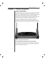
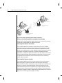
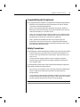
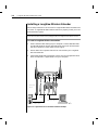
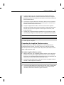
LongView® Wireless
Installer/User Guide
INSTRUCTIONS
This symbol is intended to alert the user to the presence of important
operating and maintenance (servicing) instructions in the literature
accompanying the appliance.
DANGEROUS VOLTAGE
This symbol is intended to alert the user to the presence of uninsulated
dangerous voltage within the product’s enclosure that may be of sufficient
magnitude to constitute a risk of electric shock to persons.
PROTECTIVE GROUNDING TERMINAL
This symbol indicates a terminal which must be connected to earth ground
prior to making any other connections to the equipment.
LongView® Wireless
Installer/User Guide
Avocent, the Avocent logo, The Power of Being There and
LongView are registered trademarks of Avocent Corporation
or its affliates. All other marks are the property of their
respective owners.
© 2004 Avocent Corporation. All rights reserved.
USA Notification
Warning: Changes or modifications to this unit not expressly approved by the party
responsible for compliance could void the user’s authority to operate the equipment.
Note: This equipment has been tested and found to comply with the limits for a Class
A digital device, pursuant to Part 15 of the FCC Rules. These limits are designed to
provide reasonable protection against harmful interference when the equipment
is operated in a commercial environment. This equipment generates, uses and can
radiate radio frequency energy and, if not installed and used in accordance with the
instructions, may cause harmful interference to radio communications. Operation of
this equipment in a residential area is likely to cause harmful interference, in which
case the user will be required to correct the interference at his own expense.
Canadian Notification
This digital apparatus does not exceed the Class A limits for radio noise emissions
from digital apparatus set out in the Radio Interference Regulations of the Canadian
Department of Communications.
Le présent appareil numérique n’émet pas de bruits radioélectriques dépassant
les limites applicables aux appareils numériques de la classe A prescrites
dans le Règlement sur le brouillage radioélectrique édicté par le Ministère des
Communications du Canada.
Safety and
EMC Standards
FCC class A, UL, cUL
Table of Contents
Chapter 1: Product Overview
Features and Benefits . . . . . . . . . . . . . . . . . . . . . . . . . 3
Compatibility with Peripherals . . . . . . . . . . . . . . . . 5
Safety Precautions . . . . . . . . . . . . . . . . . . . . . . . . . . . 5
Chapter 2: Installation
Getting Started . . . . . . . . . . . . . . . . . . . . . . . . . . . . . . 9
Installing a LongView Wireless Extender . . . . . . . 10
Chapter 3: Operations
Powering the LongView Wireless Extender . . . . . . 15
Informational Messages . . . . . . . . . . . . . . . . . . . . . 15
LEDs . . . . . . . . . . . . . . . . . . . . . . . . . . . . . . . . . . . . . 16
Fine-Tuning the Image Settings . . . . . . . . . . . . . . . 16
Image Adjustment Using
the LongView Wireless Extender OSD . . . . . . . 17
Appendices
Appendix A: Technical Specifications . . . . . . . . . . 21
Appendix B: Technical Support . . . . . . . . . . . . . . . 22
Appendix C: Troubleshooting . . . . . . . . . . . . . . . . . 23
1
Product Overview
Contents
Features and Benefits . . . . . . . . . . . . . . . . . . . . . . . . . 3
Compatibility with Peripherals . . . . . . . . . . . . . . . . 5
Safety Precautions . . . . . . . . . . . . . . . . . . . . . . . . . . . 5
Chapter 1: Product Overview
3
Chapter 1: Product Overview
Features and Benefits
The Avocent LongView® Wireless extender connects Keyboard, Video, Mouse
(KVM) and audio peripherals wirelessly to your computer, from up to 100
feet away. The LongView Wireless extender is a digital system that processes
analog video, inbound and outbound, utilizing a unique, proprietary
compression engine. At the heart of the compression engine is a multimedia
DSP and an FPGA that are coupled to an IEEE 802.11a radio board.
Its industry standard design makes the LongView Wireless extender
compatible with virtually any PC, display technology and operating system.
Installation is essentially Plug and Play requiring no new drivers or software.
S1
S2
PWR
Figure 1.1: LongView Wireless Extender Model
The LongView Wireless extender On-Screen Display (OSD)
The LongView Wireless extender OSD makes it simple to set up and adjust
your video parameters. Accessed from the receiver side, the OSD makes
tuning your video fast and convenient.
4
LongView Wireless Installer/User Guide
Extended
Access User
LongView Wireless
Receiver
LongView Wireless
Transmitter
Server
Figure 1.2: Example LongView Wireless Extender Configuration
Secure connectivity and 802.11a standards-based design
Advanced Encryption Standard (AES) provides secure connections through
a proprietary design based on the 802.11a standard.
The LongView Wireless transmitter
The LongView Wireless transmitter connects directly to your computer
and serves as the radio interface device enabling the computer to transmit
audio and video data. It also acts as the receiver for keyboard and mouse
signals from extended devices. The LongView Wireless transmitter contains
five chassis-mounted connectors for local video, keyboard and mouse
peripherals, in addition to power and audio in from the computer. It includes
a 3.5 foot cable with video and PS/2 keyboard and mouse connectors. Power
is supplied to the transmitter from a universal input 12 V DC switching
power supply (included).
The LongView Wireless receiver
The LongView Wireless receiver connects directly to your user interface
devices (keyboard, video monitor and mouse) and serves as the radio
interface device for these components. It receives audio and video data from
the source computer and sends keyboard and mouse data from the user
interface devices to the source computer. The LongView Wireless receiver
has five chassis-mounted connectors for video, keyboard, mouse and audio
peripherals and power. Power is supplied to the transmitter from a universal
input 12 V DC switching power supply (included).
Chapter 1: Product Overview
5
Compatibility with Peripherals
The LongView Wireless extender is compatible with the following peripherals:
•
Keyboard- The LongView Wireless transmitter and receiver support
virtually any standard PS/2 keyboard.
•
Mouse- The LongView Wireless transmitter and receiver support 2button PS/2 mice. Mice that have more than two buttons work with the
reduced functionality of a 2-button mouse.
•
Video- The LongView Wireless extender supports VGA, SVGA and XGA
resolutions up to 60 Hz refresh rate. Both CRT and LCD monitors with
standard 15-pin high density connectors are supported.
•
Audio- Speakers and headphones with 3.5 mm audio plugs are
supported on the receiver side of your LongView Wireless extender,
provided the transmitter has been connected to the sound card of your
PC with the provided audio cable.
Safety Precautions
To avoid potential video and/or keyboard problems when using Avocent products:
•
If the building has 3-phase AC power, ensure that the computer and
monitor are on the same phase. For best results, they should be on the
same circuit.
•
Use only Avocent-supplied cable to connect computers and KVM
switches. Avocent warranties do not apply to damage resulting from
user-supplied cable.
To avoid potentially fatal shock hazard and possible damage to equipment,
please observe the following precautions:
•
Do not use a 2-wire extension cord in any Avocent product configuration.
•
Test AC outlets at the computer and monitor for proper polarity
and grounding.
•
Use only with grounded outlets at both the computer and monitor. When
using a backup Uniterruptible Power Supply (UPS), power the computer
and the LongView Wireless transmitter unit off the supply.
NOTE: The AC inlet is the main disconnect.
6
LongView Wireless Installer/User Guide
2
Installation
Contents
Getting Started . . . . . . . . . . . . . . . . . . . . . . . . . . . . . . 9
Installing a LongView Wireless Extender . . . . . . . 10
Chapter 2: Installation
9
Chapter 2: Installation
Getting Started
Before installing your LongView Wireless extender, refer to the list below
to ensure that you have all the items that shipped with the product.
Supplied with the LongView Wireless extender
•
LongView Wireless transmitter
•
LongView Wireless receiver
•
Two local country power supplies
•
Audio cable
•
LongView Wireless Installer/User Guide
•
LongView Wireless Quick Installation Guide
10
LongView Wireless Installer/User Guide
Installing a LongView Wireless Extender
Follow the procedures in the To install a LongView Wireless transmitter and
To install a LongView Wireless receiver sections to properly install your new
KVM extension system.
WARNING: To reduce the risk of electric shock or damage to your equipment Disconnect the power from the unit by unplugging the power supply from the electrical outlet.
To install a LongView Wireless transmitter:
1.
Ensure that the video setting of your computer is 1024 x 768, 800 x 600
or 640 x 480 at 60 Hz refresh rate. Best performance will be achieved if
the color resolution is set to 24 bit color or higher.
2.
Power down the computer that will be connected to your LongView
Wireless extender.
3.
Unplug the peripherals (keyboard, mouse, monitor and speakers with
built-in amplifiers, if applicable) from your computer.
Transmitter
Cables
Power
Supply
Peripheral Cables
Audio Cable
Figure 2.1: LongView Wireless Transmitter Installation Example
Chapter 2: Installation
11
4.
Prepare locations for your LongView Wireless extender equipment,
computer and peripherals. Place the transmitter near your computer.
Best performance is achieved when the antennas are clearly visible and
free from obstructions.
5.
Connect the LongView Wireless transmitter cables into the computer’s
PS/2 keyboard (purple connector), PS/2 mouse (green connector) and
monitor connections (blue connector).
6.
Using the supplied audio cable, connect one end to the LongView
Wireless transmitter’s audio input connection (lime green connector)
and the other end to the computer’s audio output connection (lime
green connector).
7.
Connect your LongView Wireless transmitter to an AC power source with
one of the power supplies included with your LongView Wireless extender.
NOTE: The transmitter must be powered up before the computer.
NOTE: Use only an Avocent-supplied power supply.
8.
Power up your computer.
Connecting the LongView Wireless receiver
Virtually any industry-standard display device can be attached to the
LongView Wireless receiver, as long as it has a 15-pin D shell connector
for video input and can accept VGA (640 x 480), SVGA (800 x 600) and XGA
(1024 x 768) resolution video.
To install a LongView Wireless receiver:
1.
Select a location for your LongView Wireless receiver. Find a convenient
position for locating the LongView Wireless receiver, such as a desktop
that is near your extended display. Best performance is achieved when the
antennas are clearly visible and free from obstructions.
2.
Connect the extended display’s video input into the LongView Wireless
receiver’s video input (blue connector).
NOTE: The extended display must have a standard 15-pin D-shell RGB analog interface.
3.
Connect the extended display’s PS/2 keyboard and mouse (if applicable)
into the LongView Wireless receiver’s keyboard connection (purple
connector) and mouse connection (green connector).
12
LongView Wireless Installer/User Guide
Power
Supply
Audio Cable
Peripheral
Cables
Figure 2.2: LongView Wireless Receiver Installation Example
4.
Connect your speakers into the LongView Wireless receiver’s audio
output connection (lime green connector).
5.
Connect the LongView Wireless extender power supply into the
LongView Wireless receiver and into the AC power source.
NOTE: Use only an Avocent-supplied power supply.
6.
Connect your monitor’s power supply to appropriate electrical outlets.
3
Operations
Contents
Powering the LongView Wireless Extender . . . . . . 15
Informational Messages . . . . . . . . . . . . . . . . . . . . . 15
LEDs . . . . . . . . . . . . . . . . . . . . . . . . . . . . . . . . . . . . . 16
Fine-Tuning the Image Settings . . . . . . . . . . . . . . . 16
Image Adjustment Using
the LongView Wireless Extender OSD . . . . . . . 17
Chapter 3: Operations
15
Chapter 3: Operations
Powering the LongView Wireless Extender
The LongView Wireless extender units (transmitter and receiver) have
been factory configured to operate as a companion pair. The initial radio
link between the two units is established by the receiver, although all other
aspects of the link are controlled by the transmitter. Once the radio link is
established, mouse, keyboard, video and audio data is free to flow between
the two units.
To power up the LongView Wireless extender:
1.
Complete all of the installation steps. See Chapter 2.
2.
Power up the LongView Wireless transmitter and wait for the middle
LED labeled S2 to illuminate.
3.
Power up the monitor attached to the LongView Wireless receiver.
4.
Power up the LongView Wireless receiver.
5.
Power up your computer.
NOTE: Always power up the LongView Wireless transmitter and wait for the middle LED
labeled S2 to illuminate before powering up your computer.
Informational Messages
When the LongView Wireless receiver is powered up, it will display a
message on the computer monitor to which it is attached:
Searching for CLT_000c4116bc7b
The 000c4116bc7b is replaced by the MAC id of the radio board in your
transmitter unit. This message indicates that your receiver unit is actively
searching for its companion transmitter. When it finds the companion
transmitter, it will display a second message beneath the first:
Connecting to CLT_000c4116bc7b
The 000c4116bc7b is replaced by the MAC id of the radio board in your
transmitter unit. This message indicates that your receiver unit is
establishing the radio link with your transmitter unit. When this link is
established, both messages will be removed and the monitor will display
video information from your computer.
16
LongView Wireless Installer/User Guide
LEDs
Both the LongView Wireless transmitter and receiver contain three LEDs
visible from the front of each unit. The LEDs are labeled on the unit.
S1
S2
PWR
Figure 3.1: Transmitter LEDs
LED Conditions
S1
S2
PWR
Condition
OFF
OFF
ON
No Activity, Power is On
OFF
OFF
OFF
No Activity, Power is Off
OFF
ON
ON
Establish Link
ON
ON
ON
Connected
Fine-Tuning the Image Settings
Once the radio link has been established, and the monitor attached to the
receiver is displaying computer generated video, some fine-tuning of the
video settings may be desired. This fine-tuning should only be necessary
the first time that a LongView Wireless transmitter is used with a particular
computer; settings, once adjusted, are saved in the transmitter unit.
A mouse or keyboard driven menu, called the On-Screen Display (OSD),
enables you to perform these adjustments. The LongView extender OSD
allows you to use an Auto Setup feature to adjust the image settings, or
enables you to manually adjust any of the individual image settings. New
settings may be temporarily or permanently saved.
Main menu options
The LongView Wireless extender Main menu has two options- Auto Setup
and Link Status. The Auto Setup checks the video parameters for your source
computer and then automatically optimizes the video quality portrayed on
your monitors. The Link Status indicates the signal strength of the wireless
connection between your LongView Wireless transmitter and receiver.
Chapter 3: Operations
17
Advanced menu options
The LongView Wireless extender OSD Advanced menu allows you to finetune the video settings that were established with the Auto Setup function.
You may tune the horizontal and vertical position of the video monitor
window, as well as adjust the brightness and contrast of the video image. You
may also adjust the video clock phase in the LongView Wireless transmitter
relative to the video clock at your source computer to assure the cleanest,
sharpest video image.
Image Adjustment Using the LongView Wireless
Extender OSD
When configuring the OSD, you may use the Auto Setup function to
automatically optimize the video of your LongView Wireless extender,
or you may choose to optimize it manually. When optimizing video, best
results can be obtained by displaying a fixed image on screen during the
optimization process.
To optimize video automatically:
1.
Activate the OSD Main menu on the receiver unit by pressing and
holding the left Shift key followed by the right Shift key and then
releasing both. You may also activate the OSD via the mouse by rightclicking twice and left-clicking once in rapid succession.
2.
Optimize the video setup of your LongView Wireless extender by
selecting Auto Setup - Run. This will automatically optimize your video
setup parameters. Select Finish at the bottom to save your OSD, keyboard
and Auto Setup parameters.
-orSelect Cancel to exit without saving changes.
To optimize video manually:
If your monitor image requires further adjustment after running the Auto
Setup, you may use the Advanced Setup options from the LongView Wireless
extender OSD menu.
1.
Activate the OSD Main menu on the receiver unit by pressing and
holding the left Shift key followed by the right Shift key and then
releasing both. You may also activate the OSD via the mouse by rightclicking twice and left-clicking once in rapid succession.
18
LongView Wireless Installer/User Guide
2.
Select the Advanced tab from the OSD Main menu.
3.
On the OSD Advanced menu, use the fi ne-tuning options to make
further adjustments to your video image, as needed.
Press the Left or Right arrow keys to make adjustments for:
4.
•
Horizontal Position
•
Vertical Position
•
Brightness
•
Contrast
•
Clock Phase
Select Finish at the bottom of the Main OSD menu to save the parameters.
-orIf you wish to exit without saving changes, select the Cancel button.
Appendices
Contents
Appendix A: Technical Specifications . . . . . . . . . . 21
Appendix B: Technical Support . . . . . . . . . . . . . . . 22
Appendix C: Troubleshooting . . . . . . . . . . . . . . . . . 23
Appendix D: Understanding Wireless . . . . . . . . . . 26
Appendices
21
Appendices
Appendix A: Technical Specifications
LongView Wireless Extender Product Specifications
Mechanical
Height
1.75"
(4.45 cm)
Antenna extends 4.75” (12.07 cm) above lower
surface of housing
Width
6.25"
(15.88 cm)
Depth
5.25"
(13.34 cm)
Weight
1 lb
(0.45 kg)
Environmental/Power
Operating Temperature
0°C - 40°C
Storage Temperature
-20°C - 50°C
Power Supply
12 Vdc @ 1A from supplied 100 to 240 VAC 50/60
Hz switching power supply
Multimedia
Video Link Performance
640 x 480, 800 x 600, 1024 x 768
Video Link Compatibility
VGA, SVGA, XGA
Video Interface
VGA compatible with analog RGB
(15-Pin D-shell), non-interlaced
60 Hz refresh rate
Audio Support
Analog audio
Supported Hardware
Computer
Most standard computers with the
exception of Macintosh
Video Resolution
VGA, SVGA, XGA
Peripherals
PS/2 keyboard, PS/2 mouse, speakers
Radio
Radio Protocol
IEEE 802.11a
Radio Frequency
5150-5250; 5250-5350; 5725-5825 MHz
Radio Modulation
OFDM (Orthogonal Frequency Division Multiplexing)
Nominal Output Power
17 dBm
Range
XGA video resolution to 100 feet
Security
AES encryption with 802.1x authentication
Regulatory Compliance Standards
FCC Class A, UL, cUL
22
LongView Wireless Installer/User Guide
Appendix B: Technical Support
Our Technical Support staff is ready to assist you with any installation or
operating issues you encounter with your Avocent product. If an issue
should develop, follow the steps below for the fastest possible service:
1.
Check the Troubleshooting section of this manual to see if the issue can
be resolved by following the procedures outlined. See Appendix C.
2.
Check our web site at www.avocent.com/support to search the
knowledge base or use the on-line service request.
3.
Call Avocent Technical Support for assistance at (888) 793-8763. Visit
the Avocent web site at http://www.avocent.com/support and select
Support Phone Numbers for current phone support hours.
Appendices
23
Appendix C: Troubleshooting
No power status light on transmitter or receiver
Verify that the green LED on the separate Avocent-supplied power supply is
illuminated, indicating that the power supply is plugged in correctly.
Ensure that the power cable from the Avocent-supplied power supply is
securely plugged into the LongView Wireless transmitter or LongView
Wireless receiver unit.
No video on monitor attached to transmitter
Verify that the monitor has power.
Ensure that the video cable from the LongView Wireless transmitter is securely
plugged in to the correct connector on the computer.
Ensure that the video cable from the monitor is securely plugged in to the correct
connector on the LongView Wireless transmitter.
Verify that the computer is powered.
As a last check, plug the video cable from the monitor directly into the computer
to verify that the monitor is working and that the computer is generating active
video. If this is functioning, check that the display settings for your computer are
set no higher than a resolution of 1024 x 768 at 60 Hz refresh rate. If the monitor
does not function correctly, replace it.
No mouse and/or keyboard operation from peripherals attached to transmitter
Verify that the mouse and keyboard are connected to the correct PS/2 ports on
the computer. Match the connector color codes (green is mouse and purple
is keyboard).
If the LongView Wireless transmitter was powered up after the computer, turn off
the computer and transmitter. Power up the LongView Wireless transmitter unit,
wait for the middle LED to illuminate, then power up the computer.
Retest the mouse and keyboard by connecting them directly to the computer
and rebooting the computer. If one does not function correctly, replace the
non-functioning peripheral.
No video on monitor attached to receiver
Verify that the monitor attached to the LongView Wireless receiver has power.
Ensure that the video cable from the monitor is securely plugged in to the correct
connector on the LongView Wireless receiver.
Ensure that the video cable from the LongView Wireless transmitter is securely
plugged in to the correct connector on the computer.
Verify that the computer is powered.
Cycle power to the LongView Wireless receiver. An informational message
should appear on the monitor for a brief moment. If the message does not
appear, check the monitor by plugging the video cable from the monitor directly
into the computer to verify that the monitor is working and that the computer is
generating active video. If this is functioning, check that the display settings for
your computer are set no higher than a resolution of 1024 x 768 at 60 Hz refresh
rate. If the monitor does not function correctly, replace it.
24
LongView Wireless Installer/User Guide
Verify that all three LEDs on both the LongView Wireless transmitter and the
LongView Wireless receiver are illuminated a short period of time after power up
(30 seconds or less). If all three LEDs are not illuminated, move the LongView
Wireless receiver closer to the LongView Wireless transmitter unit until all LEDs
are illuminated.
As a last check, plug the video cable from the monitor directly into the computer
to verify that the monitor is working and that the computer is generating active
video. If this is functioning, check that the display settings for your computer are
set no higher than a resolution of 1024 x 768 at 60 Hz refresh rate. If the monitor
does not function correctly, replace it.
No mouse and/or keyboard operation from peripherals attached to receiver
Ensure that the mouse and keyboard operation cables are connected to the
correct PS/2 ports on the LongView Wireless receiver. Match the connector color
codes (green is mouse and purple is keyboard).
Ensure that the mouse and keyboard cables from the LongView Wireless
transmitter are connected to the correct PS/2 ports on the computer. Match the
connector color codes (green is mouse and purple is keyboard).
Verify that all three LEDs on both the LongView Wireless transmitter and the
LongView Wireless receiver are illuminated a short period of time after power up
(30 seconds or less). If all three LEDs are not illuminated, move the LongView
Wireless receiver closer to the LongView Wireless transmitter unit until all LEDs
are illuminated.
Retest the mouse and keyboard by connecting them directly to the computer
and rebooting the computer. If one does not function correctly, replace the
non-functioning peripheral.
No audio from speakers attached to receiver
Ensure that the audio cable is securely plugged into the line in port of the
LongView Wireless transmitter unit.
Ensure that the audio cable is securely plugged into the line out port of the
computer (should be color-coded green).
Ensure that the speaker cable is securely plugged into the line out port of the
LongView Wireless receiver unit.
Verify that all three LEDs on both the LongView Wireless transmitter and the
LongView Wireless receiver are illuminated a short period of time after the power
up (30 seconds or less). If all three LEDs are not illuminated, move the LongView
Wireless receiver closer to the LongView Wireless transmitter unit until all LEDs
are illuminated.
Retest the speakers by connecting them directly to the computer. If they do not
function correctly, replace them.
Poor video quality on monitor attached to receiver
Run Auto Setup from the OSD. Remember to click Finish to save new settings.
Ensure that the video cable from the monitor is securely plugged in to the correct
connector on the LongView Wireless receiver.
Ensure that the video cable from the LongView Wireless transmitter is securely
plugged in to the correct connector on the computer.
Appendices
25
Slow response from peripherals attached to LongView Wireless receiver
Run Auto Setup from the OSD. Remember to click Finish to save new settings.
The distance between the two LongView Wireless extender units may be too
great, reducing the quantity of data that can be sent through the radio link. Move
the LongView Wireless receiver closer to the LongView Wireless transmitter.
26
LongView Wireless Installer/User Guide
Appendices
27
28
LongView Wireless Installer/User Guide
LIMITED WARRANTY
Avocent Corporation warrants to the original retail purchaser that this product is and will be free from defects in
materials and workmanship for a period of 24 months from the date of purchase.
Additionally, all Avocent products carry an unconditional thirty-day satisfaction guarantee. If, for any reason,
you are dissatisfied with the performance of this product, you may return it to the point of purchase for a
refund of the purchase price (excluding shipping charges). This guarantee does not apply to special order
products, and may not be available through all resellers. During the warranty period, purchaser must promptly
call Avocent for a RETURN MATERIALS AUTHORIZATION (RMA) number. Make sure that the RMA number
appears on the packing slip, proof of purchase, AND ON THE OUTSIDE OF EACH SHIPPING CARTON.
Unauthorized returns or collect shipments will be refused.
Ship prepaid to:
Avocent Corporation
4991 Corporate Drive
Huntsville, AL 35805 U.S.A.
Telephone: (256) 430-4000
The above limited warranty is voided by occurrence of any of the following events, upon which the product is
provided as is, with all faults, and with all disclaimers of warranty identified below:
1.
2.
3.
4.
5.
6.
7.
8.
If non-Avocent approved cabling is attached to the unit. Poorly constructed and miswired cabling can
diminish video quality and damage equipment. Avocent manufactured cabling is built to high quality
standards utilizing overall braided shield to comply with FCC emission standards, and each cable is
individually tested under load.
If defect or malfunction was caused by abuse, mishandling, unauthorized repair, or use other
than intended.
If unauthorized modifications were made to product.
If unreported damages occurred in any shipment of the product.
If damages were due to or caused by equipment or software not provided by Avocent.
If the unit is used with non-grounded or incorrectly polarized AC power.
If the product is used in contradiction to any instruction provided by any User Guide or Instruction
Sheet provided to you or with the product.
If the product is damaged due to power surges, water exposure or act of God including lightning.
EXCEPT AS SPECIFICALLY PROVIDED ABOVE AND TO THE MAXIMUM EXTENT ALLOWED BY LAW,
AVOCENT CORPORATION DISCLAIMS ALL WARRANTIES AND CONDITIONS WHETHER EXPRESS,
IMPLIED, OR STATUTORY AS TO ANY MATTER WHATSOEVER INCLUDING, WITHOUT LIMITATION,
TITLE, NON-INFRINGEMENT, CONDITION, MERCHANTABILITY OR FITNESS FOR ANY PARTICULAR
OR INTENDED PURPOSE.
EXCEPT AS EXPRESSLY PROVIDED ABOVE AND TO THE MAXIMUM EXTENT ALLOWED BY LAW,
AVOCENT CORPORATION SHALL NOT BE LIABLE FOR ANY SPECIAL, INDIRECT OR CONSEQUENTIAL
DAMAGES (INCLUDING WITHOUT LIMITATION, LOSS OF PROFIT, LOSS OF BUSINESS, LOSS OF
INFORMATION, FINANCIAL LOSS, PERSONAL INJURY, LOSS OF PRIVACY OR NEGLIGENCE) WHICH MAY
BE CAUSED BY OR RELATED TO, DIRECTLY OR INDIRECTLY, THE USE OF A PRODUCT OR SERVICE,
THE INABILITY TO USE A PRODUCT OR SERVICE, INADEQUACY OF A PRODUCT OR SERVICE FOR
ANY PURPOSE OR USE THEREOF OR BY ANY DEFECT OR DEFICIENCY THEREIN EVEN IF AVOCENT
CORPORATION OR AN AUTHORIZED AVOCENT DEALER HAS BEEN ADVISED OF THE POSSIBILITY
OF SUCH DAMAGES OR LOSSES.
© 2004 Avocent Corporation. All rights reserved.
For Technical Support:
Email: [email protected]
www.avocent.com
Avocent Corporation
4991 Corporate Drive
Huntsville, Alabama 35805-6201 USA
Tel: +1 256 430 4000
Fax: +1 256 430 4031
Avocent International Ltd.
Avocent House, Shannon Free Zone
Shannon, County Clare, Ireland
Tel: +353 61 715 292
Fax: +353 61 471 871
Avocent Asia Pacific
Singapore Branch Office
100 Tras Street, #15-01
Amara Corporate Tower
Singapore 079027
Tel: +656 227 3773
Fax: +656 223 9155
Avocent Germany
Gottlieb-Daimler-Straße 2-4
D-33803 Steinhagen
Germany
Tel: +49 5204 9134 0
Fax: +49 5204 9134 99
Avocent Canada
50 Mural Street, Unit 5
Richmond Hill, Ontario
L4B 1E4 Canada
Tel: +1 877 992 9239
Fax: +1 877 524 2985
590-383-001B