1
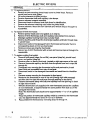
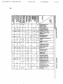
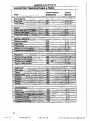
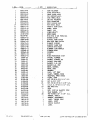
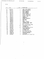
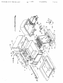
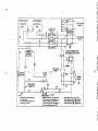
f/
3
Service Manual
Installation Instructions
Operating Instructions
Warranty Policy & Procedures
for
Electric Fryers
Model EF-30
American Wyott Foodservice Equipment Co.
P.O. Box 1829
Cheyenne, WY 82003
(307) 634-5001
FAX: (307) 637-8071
\
T 'd
1
)
TZbLSEL0TZT:Ol
T L 0 3 L E 9 L0E
llOAM MdU:WO?IJ T b : L 0 EQBZ-SO-Bnkj
Description
...............................................................................2
Installation
Thermostat Callbratlon
............................................................ :................. 2
.............................................................................. 3
..............................................................................
4
Maintenance
.........................................................................
Cleaning
................................ .
.
.
...................................... 7
P
Supply Connection
5-7
.......................................................................... 8-9
Troubleshooting Gulde ............................................................................10
Suggested Temperatures & Tlmes...........................................................1 1
Servlce
....................................................... ............... 12
Replacement Parts
*
.
.
...
General Information
I1
General Installation
1. Atways clean equipment thoroughly before first use.
(See general cleaning instructions.)
2. Check rating label for your model designation 8 electrical rating.
3. For best results, use stainless steel countertops.
4. Attach legs to units.
General Operation Instructions
1. All foodservice equipment should be operated by trained personnel.
2. Do not allow your customers to come in contact with any surface
labeled 'CAUTION HOT'.
3. Where applicable, never pbur cold water into dly heated units.
4. Where applicable, do not cook, warm o i hold food directly in liner
pans (well) pans. Always use steamtable pandinsets. etc.
5. NEVER hold food below 140°F.
General Cleaning Instructions
1. NEVER clean any electrical unit by immersing it in water.
Tum unit off and allow it to cool down before surface cleaning.
2. Always clean equipment thoroughly before first use. Clean unit
daily. Except where noted on charts: Use warm, soapy water. Mild
cleansers 8 PLASTIC scouring pads may be used lo remove
baked-on food and water scale on metal units.
3. Unplug electrical units before cleaning or sewicing. All service
should be performed by an American Wyott authorized service
agency.
General Troubleshooting
Always ask 8 check:
1. Is the unit connected to a live power source.
2. Check circuit breaker.
3. Is power switch on & pilot light glowing?
4. Check rating label. Are you operating unit on proper voltage? If the
above checks out and you still have problems, call an American
Wyoti authorized service agency (page 14-27).
E'd
T2PLSEL0T2T :01
TL03 LE9 LOE
llOAM NdU:WOW TP:LB E002-SO-9llU
DESCRIPTION
1 INSTALLATION & SUPPLY CONNECTION
installation
1. Follow General lnslallation lnslructions on
Page 1.
ELECTRIC
FRYERS
These elecliic units are designed for countertop operation.
They are used for producing
eventy cooked, perfectty fried
products.
Screw legs into the errnanentb fastened nuts
on'the four comers f the unit and tighten by
hand. Level the fryer by turning the adjustment screw at the bottom of each leg.
Do not slide unit with legs mounted, lift if
necessary to move unit.
1
I
Supply Connection
I. All units are provided with two terminal bbcks
for field wire connections on the rear of the
unit. The hrge lecminal block (marked X-Y-2)
is for power suppty connections. The smaller
auxiliary terminal bbck (marked 1.2-3)b for
connection to a fire protection circuit, or a
danger swi(ch.
All units are ptwded with two knockouts: a
3 4 . conduit size for power supply and a tn'
conduit size for auxiliary terrninal block wires.
Both knockouts are located on the rear leg
ch,annel and are accessible by removing the
rear panel.
1 2.
1
I
Remve rear panel. Mount suitable 3 4 '
wnduit fiiing.in power suppty knockout. The
kncclout hole for I& conduit f i i n g is covered
with a cbsure plug. Remove this dug and
mount a in' wnduit fining for connections to
auxiliary terminal block.
Caution: Do not remove closure plug m e r i n g
in' size bockout opening if connedions to a
fire protectioncirwit are not required. Rerrmal of the cbsure plug under this condition
may result in a shock hazard.
3. Connect field wire to the power terminal block
as indicatedan wiring diagram. Wire must be
of the type suitable for 90°C sewice and of
thickness as indicated on marking on rear
panel.
T2PLSELB12T:Ol
TL03 LE9 LBE
ELECTRIC FRYERS
SUPPLY CONNECTION
Field wire connections to auxiliary t e t m i ~bkck
l
must be of sue indicated on
marking on rear panel and sulable for 90°C service. Lead wires to the auxiliary
terminal block must be connected per instmclions on the wiring diagram located
on rear panel; depending on whether the fire protection circuit has a Normally
Open (N.O.) or a Normalb Closed (N.C.) switch. *
The auxiliary terminal block wiring must not be changed if connections to a fire
protection system are not made. The fryer is factory assembled for operating
without connedions to a fire protection system.
For testing, the rated amperages are listed below:
3 phase
240V
208V
X
I
Y
29
50
I
I
z
29
x
I
Y
z
25
44
25
I
I
NOTE: These values are nominal ratings. Field wire connections must be capable
of withstanding anticipated surges.
Replace rear panel. Ensure that equipment is grounded by installing a grounding
lead to ground lug b l e d near the terminal bkck.
CAUTION: Installing personnel should be guided by National ElectricalCode NFPA
No. 70.1978, and applicable local codes.
THERMOSTAT CALIBRATION
Checking Thermostat Calibration
The fryer themostat is carefully calibrated at the factory so that dial settings
match actual frying compound temperatures. Feld recalibration is seldom
necessary unless the unit has been mishandled in lransl or abused.
Recalibration should not be resorted to unless wnsidergble experience with
amking resuns definitety proves that the control is not maintaining the temperature to which the dial is set.
1. To check frying compound temperatures when recalibrating, use a precision
test instrument, or a good grade mercury thenometer. Fill fry tank wilh frying
compound to 'FULL' mark.
2. Flying compound temperature should b e checked at the center of the tank,
approximatety 1' to 1112' below surface of frying compound.
3. Turn the dial of the themstat being checked to the 350'F mark.
4. Allow temperature to stabilize, or until the thermostat cycles to 'OFF' three
times after starting with cokl frying oonpound. With power 'ON'. read highest
and lowest frying compound temperatures, as themstat cycles through at least
two cycles. Average the reading.
5. Thermostat s k u l d be recalibrated if temperature reading is not wlhin 10
degrees of the control knob selling (350'F 4- 1O0F).If recalibration is required,
continue wfih steps 6.7.8 and 9.
6. Remove control knob by grasping outer edgeand pulling straight oul, wilhoul
twisting or turning.
7.Hokl thermostat dial shaft 'B' (figura I ) stationary with pliers, and with a
screwdriver, turn screw 'A' clockwise to obtain a bwer temperature: or counterclockwise for higher temperature. Each 114 turn (90° rotation) of screw 'A'
represents 18'F.
8. Replace thermostat control knob
9. Recheck thermostat as in steps 4 and 5 above. If the fat temperature is not
within 20 degrees of dial setting (350°F +20°F),
I- it means that the sensing
element is inoperative and the themstatic control should be replaced.
12bLSZLBTZI:Ol
TLB3 LE9 LBE
ELECTRIC FRYERS
MAINTENANCE
,-
-&-
I
I'"
I
L---
I
flgure I
1
Removing Fly Tanks
a. Remove fry baskets.
b. Carefully grasp the black handle. CAUTION: may be hot, on the end post on top
rear corner of the fryer with the !,:ft hand, a i d the element 11fl handle resting on
fry tank front. with right hand.
c. Lift the element handle while at the same time, pulling the pbstw: handle. This
will permit lifting the elements to just above frying compound level in tank. The
element can be left in ths position for draining frying compund.
d. Again. lift the element handle wt~ilepulling the plastic handle, until the elements
lock themsetves at a higher position.
e. Firmty grasp both handles of fry tank and lifl it oul.
f. After replacing the fry tank, simpty pull the plastic handle; and at the samelime,
pull down the element handle until the elements rest on fry tank bottom.
g. Both the lifting our and bwering of elements can be done in one swing, without
Sopping at the intermediate position.
L*
Filling Fry Tank
. .
1. Ensure circuit breaker is at the 'ON' position. This is done by pressing the
'RESET or 'ON'part of the red rocker handle on the front panel.
2. Set the thermostat to 'OFF' and push in the red swilch marked 'ON-OFF' to turn
unit on. Red indicating light on the switch will come on. Turn the thermostat knob
to the 300" mark and a yellow cycling light marked 'HEAT ON' will come on.
Push the red swlch to turn it 'OFF'. The fryer control circuit has now been check
and the fryer is ready for use.
Caution: Do no1 leave elements on without frying compound in the tank.
I
a. Fill the fry lank to the 'FULL' rrork with approximately 30 lbs. of liquid or melted
frying compound. Do not overfill.
MAINTENANCE
NOTE: Do not use solid frying compound unless the fryer is equipped with a mett
cycle option. Air holes caused when packing solid frying compound into the fryer
can cause hot spots on the heating element sheath, resuling in momentary
ovemeatingof some of the frying campound and premature frying compound
breakdown. It can also damage the heating elements. If it is necessary to use
solid frying compound, it must be melled before &ding to fry tank.
Turn the thermostat to the desired frying temperature and push in the red 'ONOFF' switch to 'ON'. The yellow 'HUT ON' l~ghtwill stay on until the temperature set on the thermostat is rea:hed, then the light cycles off. The fryer is now
ready to begin frying. Afler a load has been fried, do not lower the next load into
the frying compound until the 'HEAT ON' light cycles off.
b. Do not allow frying compound level to drop more than 112' below the 'FULL'
mark. For proper operation of ltik fryer and go+ frying results, the frying compound level should be maintained.
c. Use a quality frying compound.
d. Filter the frying compound frequently, at least once a day.
e. Skim out food particles frequently with the strainerlskimmer.
I
-
1. Add at least 15% (of fry tank capacity) of fresh frying compound daily more if
possible without overloadina the tank. If 15% ot the frvina
- compound is not
-
?
bsed during hying, remove &me of the frying campound for other use (gravy.
griddle frying, etc.) to permit adding fresh frying compound.
g. Do not werkad the fry baskets. Approximately half-full or even less is correct. If
foods are taking longer 10 fry than lhe chart shows. or are n d browning. over-
kxding is a probable cause.
h. Prepare the food property:
i. Keep sah out of the frying wmpaund. Do not salt foods with the basket above
the kettle.
j. Assure a good thermostat operation.
k. Keep the fry tank and elements clean.
ELECTRIC FRYERS
-
MAINTENANCE & C L E A ~ ~ , @ G
2. If the fryer is equipped with the 'Automatic Melt Cycle' -lion,
the fry tank can be
filled with solid frying compound. The men cycle can also be used to melt frying
compound which has solidified since its last usage.
To operate the melt cycle, push the whiie switch marked 'MELT ON' to 'ON'.
The fryer may be lefl unattendedlduringthe melt*cle operation. It takes approximately 18 minutes to melt 30 lbs. of solid frying compound. After the solid
frying compound has metted, push the mett cycle switch to 'OFF'. The fryer will
then heat the frying compound to the temperature set on the thermostat.
Cleaning
I . Follow General Cleaning lnstructlons on Page 1.
a.
Before the first time use, clean the protective oil from the bright pans and
interior of tank with a solmion of washing soda or other grease dissolving
rnateriial.
2. The frequency of cleaning shoukl depend on the load conditions. Set a definite
cleaning schedule corresponding to how hard the kettle is used. Cleaning should
be done at least once a week.
a. Turn the thermostat to '0kl and allow unit to cool down.
b. L i the elements to drain position. Wire brush or scrape elements to remove
any solids adhering to the elements.
c. Raise the elements. Lift out fry tank. Strain the frying compound into a
clean container.
d. Replace empty fry tank. .lower elements to rest inside the tank.
e. Add water to the 'FULL' rnbrk on tank.
Add any good gradeof cleaner, following cleaner instructions.
f.
Turn
the thermostat to 250°F and let the heating unil bring the solution to a
g.
bil.
h. billong enough to bosen or dissolve all varnish or carbon deposits.
approximatety 30 minutes.
i. Turn the un2 off and lift out the elements to drain position.
If necessary, clean the thermostat bulbs using a long-handledfiber or
j.
plastic brush and mild soap solution.
k. Rinse with clean water to remove all cleaning mixture.
I. Lifi owthe fry tank and drain. Repeat steps j and k with fry tank.
m. Rinse the inside of the tank wilh 2 cups of vinegar.
n. Rinse with clean water until the vinegar odor is gone. The fry tank must be
thoroughty rinsed, since even a trace of cleaner left inside the tank will ruin
frying compound.
o. Dly thoroughby. Replace the tank and lower the elements.
p. Shut the unit off and cover tank until ready for further use.
q. Thin tilms of oil subjected to frying temperatures quickly form into a gummy
consistency. In order to avoid these gum formations. keep all other surfaces
of the unit clean by polishing stainless steel surfaces wilh a damp cloth. To
remove discolorations or oil film, a non-abmsive cleaner may be used.
7
3 T ~ 'd
6
TZbLSTLBT2T:Ol
TL03 L69 LBE
I
I
n l v t c n l b m l v vv
I
uI
I
SERVICE
Service
I . Cautlon:
a. Before servicing the unit, d k e certain the fry tank frying compound and
elements are cool enougkto avoid bums. A
b. Before opening corrgonent aacess panels, ensure the eledrical power
supply cord to main terminal bbck and power supply to the auxiliary
terminal block BOTH have been disconnected.
2. To replace red 'ON-OFF switch, yellow cycling light or circuit breaker, while
'MELT ON' switch and melt cycle control assembly for melt cycle option:
a. Remove the thermostat control knob by grasping outer edge and pulling
straight out. without twisting a turning.
b. Remove two screws at top of front panel. Pull top edge to open.
c. Disconnect leads to switch, light or circuit breaker and remove the damaged
mrmnent. Mark dixonneded leads to .dentiry them.
t new circuit breader (or r e H cycle oohtrol) with fasteners prod. ~ o u hthe
vided. The new switch or ligv is snapded into place from the front of the
panel.
e. Connect leads to corresponding terminals on new component. Check
completed circuit against circllit digram on rear panel.
Reverse steps a and b to close front panel.
f.
3. To replace magnetic contactor, terminal bbck, ground lug or auxiliary terminal
a.
b.
c.
d.
e.
block:
Remove four screws securing the rear panel to the unit. Let the rear panel
fall down straight before pulling it out.
Disconnect leads l o the damaged component.
Connect the leads lo cofreqmding terminel on the new component.
Remove screws securing thedamaged component to the mounting panel.
Remove the damaged compnent and install a new compnent, in the
same position.
Check completed circuil against circuit diagram on rear panel.
Mount the rear panel and put unit in operation.
1.
g.
4. To replace blown fuses or fuse block:
a. Open rear panel as i n step h above.
b. Remove damaged fuses and replace with 40 ampere one-time fuse.
c. To replace fuse block, remove fuse and disconnect wire leads to the
damaged fuse block. Mark disconnected leads to identfy them.
d. Replace new fuse block in the same position.
e. Conned leads to correspondmg terminal on new fuse block. Check completed circuit against circuit diagram on rear panel.
31,137 'd
i2bLSTL0i2l:Dl
l L 0 3 LC9 LQE
ELECTRIC FRYERS
SERVICE
hi
5. To replace element:
a.
b
c.
d.
e.
1.
g.
Remove screws securing pwotal head cover to pivotal head. Remove
pivotal head cover and gasket.
Lifi up the elements to drain position.
Remove thermostat bulb and capillary tube elamps.
Remove element supporl assembty.
Disconnect leads to element and mark them for identifiication.
Remove the element retaining nuts inside the pivotal head.
Remove element. Mount the new element and reverse steps a through f to
reassemble.
6. To replace hi-limit thermostat: I
a. Remove pivotal head cover and gasket as in step 5a.
b. Remove hi-limit themrostaiibulb and capillary tube clamps from element.
c. Dislodge capillary bushing fmm hole in pivotal head.
d. Remove bushing and thread the thermostat cepillary and bulb through hole
in pivotal head.
e. Disconnect leads to the da%magedhi-ljmrt thermostat and transfer them to
comespondmg leads on the new thermostat.
1.
Remove screws securing the thermostat.
Secure
new hi-limit thermostat with screws and reverse steps a through d to
g.
reassemble.
7. To replace cycling thermostat:
a. Remove front panel (steps2a and 2b), rear panel (step 3a), pivotal head
cover, and gasket (step 5a).
b. Remove cover on back of i n d post, located on right rearcomer of the unit.
Remove thermostat capillary and bulb from the pivotal head as in steps 6b
c.
through 6d.
d. Disconnect nuts securing the thermostat coil to end post and to pivotal
head. Both are accessible from rear of end post.
e. Oixonnect leads to the damaged thermostat and mark them for identification.
f.
Remove screws securing the thermostat to front panel.
g. Manewer the thermostat to rear of the unit (through right side passage)
and then into the right side end post (through opening on top panel).
h. Remove t h e m s t a t abng with bulb and capillary from the opening on back
of right side end post.
W~ndthe t h e m s t a t coil (Supplied with new thermosat) around the capillary
I.
of new thermostat. at approximately the same position from bulb as on the
damaged thermostat.
Note: The t h e m s t a t coil should cover approximtely 'I1' to 12' of capillary
length.
Wrap
the portion of thermostat capillary which is covered by the therrnostat
j.
mil, into approximately two turns of 1re' to 2' diameter.
k. Reassemble the themasat by reversing steps 7a through 7h.
RUG-05-2003 07:44 FR0m:RPW WYOTT
High rmislure m e n l
ir, f
a d belly friod
lnadequale frying corrpound
1lClDVer
Conlamirutim d frjirg
~ ~ m p o u (duo
r d b sin a
dher la%* nra1ori;lI)
Frying in foem
Faoj
bed
o*cr
being fried may
qualiv
mm
exbust slack
Pox q w l i y d lryinp,
cPrrpolud-eirherinto1
a ahar wrm6sive uae
Cxking lime too h
n
lrakquate filleting d
IyinQrsmvwndioxccsrjve
cmmhr in Iq lank
Kmping lood in fyitq
mmpouod ahar cmkng
l ~ d o q m r cle~ning
s
dfy lank
AMERICAN W O l T
SUGGESTED TEMPERATURES & TIMES
1
I
IFahrenheit)
Tlme In
Minutes
350
2.3
Control Setting
Frenchtoast
1
.
....
Gi;
ited,
5...s;o'.?.,
.
:.,,,I
.
bench.fried,san&qj&es.
:.;. ;,., $
': - :
. . .
0
...
:...
:
~ ~ , l :.',~ , 2 ' . .
I
NO.
1
Z
3
6
5
G
7
8
10
11
12
13
I1
15
16
17
19
20
22
23
24
25
26
27
28
29
31
32
33
36
35
36
37
38
39
10
41
42.
43
46
46
47
48
49
50
51
52
54
55
58
59
60
61
DESCRIPTION
A
TANK WELDHENT
PIVOT HEAD UELD.
FRONT PANEL ASSY
TOP SUPPORT ASSY.
SIDE P m E L WELD.
LEG PAD UELDNENT
POST THEM END
POST LOCKING END
TOP CROSS ANGLE
FRONT 6 REAR CHAN.
PANEL, REAR
PANEL, TOP
LINER WELD'T
KNOB GUARD
n/s 8-32 x 318 TRHD
BOTTOH COVER
PIVOTAL HEAD COVER
END POST BACK COVER
FLEHENT SUPPORT
ELEMENT CLAMP BAR
CONTCTR MTG PANEL
ELEMENT LIPT HANDLE
PLUNGER BODY
PLUNGER
PLUG
WIRE PROTECTION STRP
SPRING, PLUNGER
GASKET, PIVOTAL HD
GASUT. END POST
BASKET. L.A. PRY
BASKET R.H. PRY
KNOB, CONTROL
KNOB. PULL
GBOWT
PLUG. 718" VENT
C U n P . THERnO, BULB
HOLEPLUG, KNOB INDEX
C U P , TUBE
M/S PN HD 6-32 X 116" S. S
H/S 6-23 X 3/8"
nls IR HD 1 0 4 x 318" S.S.
I1.H.C.S.
10-24 X 112" S.S.
HEX NUT 6-32
srs
LEGS
NUT, 5/8"-18 ELASTIC STOP
PLAT WASHER, 1 / 4 "
POP RIVET 1/8" X 118" S.S.
MARKER. SUPPLY
MILKER, DlSCONNECI
LABEL, GROUND WRNG
LABEL, RESET
W I R I N G DIAGRAM
LABEL
1NO.
62
66
67
1
QTY
1
2
1
68
1
63
70
71
72
7 2n
7
1
1
2
2
73
1
74
75
76
77
78
79
80
83
1
2
84
86
87
88
89
90
2
4
1
1
2
6
23
2
15
1
1
91
I
2
92
95
2
1
96
1
2
97
( DESCRIPTION
LABEL, FUSE WARNING
CONTACTOR, MAGNETIC
BLOCK, TERHINAL
BLOCK,
WIRE CONNECTOR
SUIZCH, LIGHTED PIB
SUITCH. HIGH LIHIT
ELEEENT, 6OOOU 208V
ELEHENT, 2 4 0 V
THERHOSTAT
SPRING, THERMOSTAT
WIRE T I E S
FUSE BLOCK
FUSE
CIRCUIT BREAK!iK
INDICATOR LIGHT, AMBER
NUT "u" # I 0 ZN
$10 X 3/8" SHT HET SCREW
110-24 HEX .lCP S.S.
TINNERHAN NUT
H/S PN HD 8-32 X 112 S I S
LABEL, CONNECTION
SOIJDERLESS LUG
CAP BULB CLAMP
MIS 8-32 x 1 S / S RD
NUT 8-32 HEX MET LOCK
GRAPHICS APCIIWOTT
INSULATION
RIVET POP 1/8" X 15/64'' S / S
IERHINAL
L
RUG-05-2003
07:47 FR0M:RPW WYUTT
GAS PARTS LIST
PART #
DESCRIPTION
3525-03-56
PILOT TUBE COMPLETE WITH TIP 4 N D SCREW
3527-02
BURNER TUBE WITH ELBOW
3503
BRASS PILOT TIP
3532
BURNER COMPI FTE WITH CAP -NATURAL GAS, 1000 BTU
3533
BURNER COMPLETE WITH C.4P - PROPANE GAS, 2500 BTU
3530
RI JRNER CONTROL VALVE
3505
PILOT CONTROL VALVE
3511
BURNER CONTROL KNOB
3501
GAS PRESSURE REGULATOR FOR NATIJR4L GAS
3553
GAS PRESSURE KEGULATOR FOR PROPANE GAS
3507
MINI PILOT (THERMOCOUPLE)
3508
SAFETY PILOT VALVE
3507-08
SAFETY PILOT FOR INDIVIDUAL SECTION
2701-9214
RADIATION OR HEAT DISTRIBUTION PLATE
3570
BRASS ORIFICE 1/2"
AUXILIARY TE-1
BLOW
FG+I FIREPROTEC~CN SYSTEM
CONTACTO(I
CIRCUIT BRK.
REGULATING
l . I.
-L . ,m. I
a D c b Comrtlsn
..
~han
bloc. c-Usumfi.
m v s a weaam@kdesd
L
UrC.,dW(ulY).C.cQ3v..ila
r w h ~ 1 . w
Pat-w..
Car* c.ol I*.