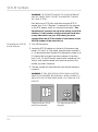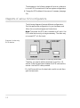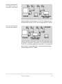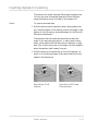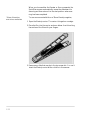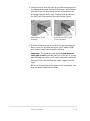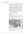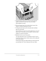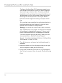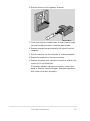
1
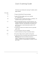
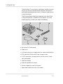
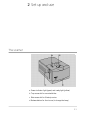
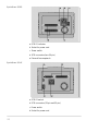
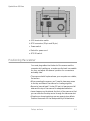
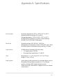
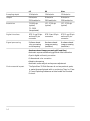
Table of contents
Quick Scanning Guide
iii
1 Introduction
Macintosh system requirements
PC system requirements
Technical Support
Registration card
Unpacking
1-2
1-3
1-4
1-4
1-5
2 Setup and use
The scanner
Positioning the scanner
SCSI guidelines
SCSI ID numbers
Installing a SCSI adapter in a PC
Connecting the scanner to your computer
Diagrams of various SCSI configurations
Turning on the scanner
Inserting originals for scanning
2-1
2-3
2-4
2-6
2-7
2-7
2-8
2-10
2-11
i
3 Care and maintenance
Maintenance
Changing the lamp
Changing the fuse (ES scanner only)
Troubleshooting
SprintScan 35 warranty
SprintScan 35 service
Polaroid Offices and Service Centers
Radio and television interference (LE and Plus)
Radio and television interference (ES)
Appendix A: Specifications
Index
© Copyright 1996 Polaroid Corporation
All rights reserved.
ii
3-1
3-2
3-4
3-6
3-8
3-8
3-9
3-11
3-12
A-1
I-1
Quick Scanning Guide
Use this as a quick reference for scanning. For details, see the
pages indicated.
See page:
1-5
1 Unpack the SprintScan 35 scanner package.
2-7
2 Install a SCSI host adapter card in your computer
(PC-compatibles only).
2-6
3 Change the SCSI ID number of the scanner, if necessary. The
scanners are factory set to SCSI ID number 6.
2-7
4 With all equipment turned off, connect the scanner to your
computer using the SCSI cable provided. If the scanner is the
last device in the chain, use a terminator at the scanner (LE
and ES scanners) or move the termination switch to ON
(Plus scanner).
2-10
5 Plug the power cable into the scanner and into a grounded
power outlet.
2-10
6 Turn on the scanner, then your computer.
––
2-11
––
7 Install the software according to the software manual.
8 To scan an image, insert an original into the scanner.
9 Initiate the scan from the software (see the software manual).
Warning: Please follow the detailed instructions in
chapter 2, Setup and use for connecting the equipment.
Improper connection could damage your computer, the scanner, or both.
iii
1 Introduction
The Polaroid SprintScan 35 LE, ES, and Plus slide scanners
allow you to capture and convert film images into electronic
files that you can edit and incorporate into your documents
and presentations. The scanners can be connected to a
Macintosh computer, or an IBM-compatible computer with a
SCSI host adapter installed (see page 2-7). The models are
similar in function and differ as indicated.
For Macintosh users, the SprintScan 35 scanners are shipped
with a software plug-in that allows you to acquire images in
any Adobe PhotoShop plug-in compliant application, then
edit and print them from within the application. For Windows
users, the SprintScan 35 scanners are shipped with Polaroid
SprintScan TWAIN driver software and are compatible with
both Windows 95 and Windows 3.1 operating systems.
All three models can accommodate 35mm mounted transparencies and filmstrips. The SprintScan ES and Plus scanners
can also accommodate SuperSlides (36x36mm). The units can
operate at voltages from 100V to 240V.
The SprintScan 35 LE and ES scanners capture images at 10
bits per color; the Plus captures images at 12 bits per color.
The scanners convert the image data into 8 bits per color (256
levels per color).
1-1
Macintosh system requirements
Minimum
• A Macintosh II family, Quadra family, PowerPC or
Powerbook computer (use appropriate Powerbook SCSI
cable as required)
• System 7.01 or later
• 12 MB of RAM
• A 256 (8-bit) color monitor
Recommended
• A PowerPC computer
• System 7.5
• 32 MB of RAM
• A 24-bit color monitor
SprintScan plug-in
The SprintScan plug-in requires:
• 2 MB free hard disk space
• 4 MB from the application memory
Note: Application memory is the amount of memory avail-
able for the application after the sytem has started. The imaging application should have enough memory (combined RAM
and hard disk memory) to allow for about three times the
maximum image size you plan on scanning. This means you
should have the minimum memory plus enough memory for
the maximum scan size. Note that the maximum scan size
depends on the images and resolutions you want to scan. For
example, scanning a 35mm slide at 500 dpi resolution
requires about 1.2 MB of memory. Scanning the same slide at
1950 dpi requires 18 MB of memory, and at 2700 dpi, about
32 MB of memory, which means utilizing the swap area on
the hard disk.
If you do not have the minimum required configuration for
using the SprintScan 35, contact the dealer from whom you
purchased your computer system.
1-2
PC system requirements
Minimum
• An IBM PC or compatible with 386SX, 486 or Intel Pentium
microprocessor
• DOS 5.0 or later
• Microsoft Windows 3.1 or Windows 95 operating system
• 12 MB of RAM
• A 256 (8-bit) color video adapter*
• An ASPI-compliant SCSI-2 interface board
Recommended
• An IBM PC or compatible with an Intel Pentium microprocessor
• Microsoft Windows 95 operating system
• 32 MB of RAM
• High color (16-bit) or better video adapter at 1024 x 768
screen resolution
If you do not have the minimum required configuration for
using the SprintScan 35, contact the dealer from whom you
purchased your computer system.
*Note: Adobe Photoshop 3.0x and above requires at least a
256 (8-bit) color video adapter in order to operate.
Introduction
1-3
Technical Support
Before you call, have ready the following information:
• The model of your computer, including the kind of processor,
and the amount of RAM you have
• The model and serial number of your SprintScan 35
• A list of other devices attached to your system, such as CDROM drives, printers, external hard disks, and other SCSI
devices
• A list of any other cards and drivers that you are using,
including video card and driver
• Other applications you are using
• A description of the problem and the wording of any error
messages on your screen when the problem occurs
Run a system diagnostic
We recommend that you run a system diagnostic utility to
provide detailed information about your system before you
call.
Call us
You may call Polaroid toll-free from within the U.S.A. at
1-800-432-5355, or fax the information about your problem
to 1-617-386-9688, Monday through Friday, 8 A.M. to
8 P.M. Eastern Time. We offer a variety of Customer Support
Services; call us for details and applicable fees. You may also
write to Electronic Imaging Technical Support, Polaroid
Corporation, 565 Technology Square 3B, Cambridge, MA
02139. In Canada, call toll-free at 1-800-268-6970. Outside
North America, contact the Polaroid office nearest you (see
pages 3-9–3-10).
Internet support
Technical Support is also available over the Internet. Connect
to our web site at: http://www.polaroid.com
Registration card
Be sure to fill out and mail your registration card. As a registered owner, you’ll receive information about software
updates and about the availability of new scanning products
from Polaroid.
1-4
Unpacking
The SprintScan 35 is a precision instrument. Handle it as carefully as you do your hard drive and computer. Save the protective packing materials and carton in case you need to move
or ship the scanner.
The following figure shows the components you should find
in the packing boxes, in addition to this manual. If you are
missing anything, contact your dealer immediately.
a SprintScan 35 Slide Scanner
b Power cord
c A filmstrip carrier for a negative strip or unmounted slide film
d SCSI cable with 25-pin and 50-pin connector ends
e A SCSI terminator (not required for the Plus, which is inter-
nally terminated)
f Polaroid software
g Polaroid manuals (not shown)
h Product registration card (not shown)
i Spare lamp inside front cover (not shown)
Introduction
1-5
2 Set up and use
The scanner
a Power indicator light (green) and ready light (yellow)
b Top access slot for mounted slides
c Side access slot for filmstrip carrier
d Release button for front cover (to change the lamp)
2-1
SprintScan 35 ES
a SCSI ID indicator
b Socket for power cord
c Power switch
d SCSI connectors (two 50-pin)
e External fuse receptacle
SprintScan 35 LE
a SCSI ID switch
b SCSI connectors (25-pin and 50-pin)
c Power switch
d Socket for power cord
2-2
SprintScan 35 Plus
a SCSI termination switch
b SCSI connectors (25-pin and 50-pin)
c Power switch
d Socket for power cord
e SCSI ID switch
Positioning the scanner
You must plug cables into the back of the scanner and the
computer while setting up, so make sure the back is accessible
for now, and adjust the scanner’s position for convenience
and safety later.
• The scanner should be placed near your computer on a stable,
flat surface.
• When operating the scanner, you’ll need to have easy access
to the top and sides of the scanner for loading originals.
• Be sure to leave at least 2 inches (50 mm) of space around all
sides and the top of the scanner for adequate ventilation.
• Leave clearance on the sides at the front of the scanner so that
you can slide the filmstrip carrier through the side access slot.
• Vibrations or bumping during use can cause picture defects.
Position the scanner for the least possibility of disturbance.
Setup and use
2-3
Warning: Except for the lamp (and one fuse on the ES), noth-
ing inside the scanner is user serviceable. Do not attempt to
disassemble the scanner. To do so could result in severe electrical shock and damage to the scanner. This action may also
void your warranty. Contact Polaroid Technical Support if
the scanner is malfunctioning. (See Technical Support on page
1-4, and chapter 3, Care and maintenance).
SCSI guidelines
About SCSI chains
The SCSI system uses special cables and termination to achieve
communication between the computer and peripheral devices.
To function properly, the combined length of the entire cable
system must not exceed 19 1/2 feet (6 meters) and must include
the appropriate number of terminators. Termination maintains
the clarity of the SCSI signal along the chain of devices. A
SCSI chain must always be terminated at both ends. Incorrect
termination can permanently damage the computer, scanner,
or any other device along the SCSI chain. Refer to the following
guidelines and diagrams for more information.
Termination
The SCSI chain must be terminated at both ends of the chain.
The beginning of the chain is typically the computer. In a PC,
make sure the SCSI host adapter is terminated; see instructions for the SCSI adapter. (However, if you have an internal
SCSI hard drive and only one SCSI adapter, then the hard
drive should be terminated and not the adapter.) Most
Macintosh computers include a hard disk which is internally
terminated. If your Macintosh computer does not include an
internally-terminated hard disk, you must place an external
terminator on the first device after the computer, between the
device and the SCSI cable to the computer.
Intermediate devices in the chain should not be terminated. If
you have an internally-terminated device, place it at the end of
the chain. (Check the manual for the device to determine if it
is internally terminated or not.) If none of your devices are
internally terminated, place an external terminator on the last
device.
2-4
The SprintScan 35 LE and ES scanners are unterminated. If
one of these scanners is the last device in the chain, add a terminator. The SprintScan 35 Plus has a termination switch to
enable (turn on) or disable (turn off) the internal termination.
The unit is shipped with termination off. See the illustrations
on pages 2-8–2-9 for examples of various SCSI configurations.
Powerbook note: According to Apple Computer, even
though this computer has an internal hard disk, you should
treat it as an unterminated device. Refer to the documentation
included with your Powerbook.
Connection tips
WARNING: ALL CONNECTIONS MUST BE MADE WITH
THE SCANNER, THE COMPUTER, AND ALL SCSI DEVICES
TURNED OFF.
• Always make SCSI connections firmly, connecting the clips or
tightening the screws that secure cables and terminators. Most
problems with SCSI devices are connection problems along
the SCSI chain.
• The SprintScan 35 ES scanner has two 50-pin SCSI connectors
and the LE and Plus scanners have two SCSI connectors – one
50 pin and one 25. A SCSI cable can be connected to either
port without affecting the performance of your equipment.
• Each device on a SCSI chain must have a unique SCSI ID
number. These numbers are described in the following
section.
• If a 50-to-50 pin cable is required, be sure to use a cable
which meets the SCSI-2 specification, such as an Apple cable.
Setup and use
2-5
SCSI ID numbers
WARNING: TO PREVENT DAMAGE TO YOUR HARDWARE
AND SOFTWARE, READ THIS SECTION BEFORE TURNING
ON YOUR SYSTEM.
Each device on a SCSI chain must have a unique SCSI ID
number from 1 to 6. (Number 7 is reserved for the computer
or the SCSI adapter, and 0 for the internal hard disk.) The
SprintScan 35 scanners are set at the factory to SCSI ID
number 6. If this number conflicts with your hard drive
or any other device on your SCSI chain, you must
change either the SCSI ID number of the scanner or the
SCSI ID number of the other device.
Changing the SCSI ID
of the scanner
1 Turn off the scanner.
2 Locate the SCSI ID selector on the back of the scanner (see
below). On the LE or Plus model, press the button marked (-)
or (+) above and below the switch to change the number to an
ID number that is unique from other numbers in the chain,
from 1 to 6. On the ES model, insert a small screwdriver into
the slot and rotate the wheel until the arrow points to the
number you want. See below.
3 The new number will take effect the next time the scanner is
turned on.
WARNING: IF TWO DEVICES ON A SCSI CHAIN HAVE THE
SAME SCSI ID NUMBER, NEITHER WILL WORK CORRECTLY,
AND DATA MAY BE DAMAGED WHEN YOU TURN ON THE
DEVICES.
The SprintScan 35 LE
and Plus scanners
2-6
The SprintScan 35 ES
scanner
Installing a SCSI adapter in a PC
If you are using a PC-compatible computer, you must have a
SCSI host adapter installed in your computer for connection
to the scanner. We recommend an Adaptec SCSI host
adapter. Before connection, be sure the settings are correct;
check the documentation for your adapter. The SprintScan 35
scanner is compatible with most Windows ASPI-supported
adapters (such as Adaptec).
For detailed information about installing the card, refer to the
instructions provided with your adapter card.
Connecting the scanner to your computer
WARNING: ALL CONNECTIONS MUST BE MADE WITH THE
SCANNER, THE COMPUTER, AND ALL OTHER CONNECTED
EQUIPMENT TURNED OFF. PAY STRICT ATTENTION TO THE
SEQUENCE OF INSTRUCTIONS IN THIS SECTION. FAILURE TO
COMPLY MAY RESULT IN DAMAGE TO YOUR COMPUTER
AND/OR THE SCANNER. SUCH DAMAGE IS NOT COVERED
BY THE WARRANTY.
1 Turn off your computer, and then turn off the scanner.
2 Connect the 25-pin end of the data cable to the SCSI port on
the back of your computer and the 50-pin end to the 50-pin
port on the back of the scanner.
Warning: Use only the cable supplied with the scanner.
The second port can be used to connect another SCSI device
to the chain, using another SCSI cable.
3 Terminate the signal at the last device in the chain. If the ES
or LE scanner is the last device, connect the terminator provided to the 50-pin port. Then connect the SCSI cable to the
terminator. If the Plus is the last device, turn termination on
using the switch. Be certain to use only SCSI-specified cables
for all other connections in the chain.
Setup and use
2-7
The diagrams on the following pages will serve as a reference
to correct SCSI connections for various system configurations.
4 Change the SCSI address of the scanner if necessary (see page
2-6).
Diagrams of various SCSI configurations
The following diagrams illustrate different configurations.
Find the appropriate configuration for your hardware, and
follow the connection diagram and instructions.
Note: The shorter the SCSI chain, the better it will work. Use
SCSI cables that are only as long as necessary. The chain may
not exceed 19 1/2 ft. (6m) total.
Scanner is the only
SCSI device
The hard disk of the computer is internally terminated.
Therefore, you need to add the terminator to an ES or LE
scanner. Place the terminator between the SCSI cable and the
scanner. Use the SCSI cable provided.
*For the Plus model, turn the termination switch on and disregard the terminator.
2-8
Scanner and another
SCSI device which is
internally terminated
Place the terminated device at the end of the chain and do not
add any additional terminators. For the Plus model, be sure
the termination switch is off. Use only approved SCSI cables.
Scanner and another
unterminated device
Place the scanner at the end of the chain and terminate it with
the external terminator (LE and ES) or the termination switch
(Plus). Do not add any additional terminators. If one external
device has an internal terminator, see the previous example.
Use only approved SCSI cables.
Setup and use
2-9
Turning on the scanner
1 With the scanner off, plug the power cord provided into the
scanner, and then into an appropriate grounded outlet. The
scanner can operate over a voltage range from 100 to 240
VAC.
2 Turn on the scanner; the switch is next to the power
connector. The POWER indicator light on the top of the unit
will light. The scanner will perform a self-test that lasts for a
few seconds. If no problems are detected, the READY light
will stay lit.
3 Once the ready light is lit, turn on your computer.
2-10
Inserting originals for scanning
The scanner can accept mounted 35mm slide transparencies.
You can also scan unmounted slides and 35mm filmstrips
using the filmstrip carrier included in the accessory kit.
Slides
To insert a mounted slide,
1 Hold the slide so that the emulsion side is facing away from
you, toward the back of the scanner, and so the image is right
side up for the LE scanner and upside-down for the Plus and
ES scanners (see below).
The emulsion side is the side that would face toward the
screen if you were using a projector. In many cases it has a
duller, more matte-like finish than the non-emulsion or base
side. Also, if there is any text in the image, it will be readable
when the emulsion side is away from you.
2 Place the slide into the access slot on top of the scanner, as
shown in the following figures. Make sure the slide is firmly
seated in the mechanism.
SprintScan 35 LE
scanner
Setup and use
SprintScan 35 ES and
Plus scanners
2-11
When you choose either the Preview or Scan commands, the
SprintScan scanner automatically moves the slide down for
scanning and then returns it to the start position when scanning has been completed.
35mm filmstrips
and other materials
To scan an unmounted slide or a 35mm filmstrip negative,
1 Open the filmstrip carrier. The carrier is hinged on one edge.
2 Place the film into the carrier as shown below. Avoid touching
the surface of the film with your fingers.
3 Remove any slide that may be in the top access slot. You can’t
insert the filmstrip carrier while a slide is in the scanner.
2-12
4 Insert the carrier from the right (as you face the scanner) into
the side access slot near the top of the scanner, with the emulsion side of the film strip facing the rear of the scanner and
the image right side-up for the LE scanner and upside-down
for the ES and Plus scanners. See the following figures.
SprintScan 35 LE
scanner
SprintScan 35 ES and
Plus scanners
5 Slide the filmstrip carrier to the left to line up the image you
want to scan. As you slide the carrier, you’ll detect a slight
click as each frame is positioned for scanning.
Important! The filmstrip carrier moves in one direction –
from right to left as you face the front of the unit. If you go
past the image you want, you’ll have to remove the carrier all
the way from the left side and then insert it again from the
right.
When you choose either the Preview or Scan commands, scanning proceeds as described for slides.
Setup and use
2-13
3 Care and maintenance
Maintenance
The SprintScan 35 scanners require very little maintenance. If
the scanner becomes dirty, unplug it, then simply wipe it off
with a damp (not wet) cloth with some mild soap or detergent. Do not use harsh cleaners as they could damage the case
or mar its appearance.
Warning: Do not use any kind of spray directly on the scanner. The spray could get inside the scanner, damaging the
bulb, the lens, or the mechanism.
All the scanners are shipped with a spare lamp. See page 3-2
for lamp replacement.
Fuse replacement
The SprintScan 35 ES has an accessible external fuse that can
be replaced (see page 3-4). The SprintScan 35 ES has other,
internal fuses, and the LE and Plus have only internal fuses. If
you suspect an internal fuse has failed, do not attempt to disassemble the scanner. To do so could result in severe electrical
shock and damage to the scanner. This action may also void
your warranty. Contact your service representative or
Polaroid Technical Support.
3-1
Changing the lamp
The scanning lamp should be replaced if it begins to flicker or
dim, or if the ready light does not come on. A spare lamp is
included inside the scanner’s front cover.
Use only a 4-Watt tubular fluorescent lamp with a 5/8-inch
diameter. The U.S. lamp specification is F4T5 Cool White
(CW), and the European/Asian specification is TL4W/33.
Contact your dealer for the proper replacement lamps.
Important: The quality of scans can be affected by dirt or
smudges on the lamp. The best assurance of a clean lamp is to
wear cotton gloves while changing the lamp and to avoid
touching the lamp except at the ends.
Follow these steps to change the lamp:
1 Remove the slide or filmstrip from the scanner.
2 Turn off the scanner.
3 Open the front cover by pressing the release button under-
neath the front and lifting the cover upward, as shown in the
following figure. The cover lifts completely off.
4 If the lamp is still hot, wait for it to cool for a few minutes
before attempting to remove it.
3-2
5 Grasp the lamp by both ends, near the housing, and pull
upward one end at a time to free it from the sockets.
Some resistance is normal.
6 Remove the spare lamp from inside the front cover of the
scanner. It’s held in place with two clips.
7 Holding the new lamp by both ends, push each end down-
ward into the sockets.
Some resistance is normal, but avoid excessive force. If an end
does not go in fairly easily, you may need to rotate the lamp
slightly to line up the connectors.
8 Replace the front cover of the scanner.
You may now want to turn on the scanner so that it can run
the self-test. Both the power indicator light and the ready light
should glow steadily.
Discard the old lamp in an appropriate way, just as you would
any used light bulb. Order a new spare from your dealer.
Care and maintenance
3-3
Changing the fuse (ES scanner only)
The fuses in the SprintScan 35 ES scanner are meant to prevent damage to the scanner’s circuitry in case of inappropriate power surges or electrical short. Fuses may sometimes
simply blow out from old age. If you have a fuse failure, you
should always try to find out the cause. Replacing the fuse
alone may not solve the problem. Contact your dealer or
Polaroid Technical Support whenever you suspect a blown
fuse.
Only one fuse is user accessible; this section describes how to
check and replace that fuse. However, it is best to have a
qualified technician deal with fuse problems.
Warning: The scanner has internal fuses as well as the exter-
nally accessible fuse. If you suspect an internal fuse has failed,
do not attempt to disassemble the scanner. To do so could
result in severe electrical shock and damage to the scanner.
This action may also void your warranty. Contact your service representative or Polaroid Technical Support.
Use only a fuse that meets the specifications of the SprintScan
35 ES scanner: 1.6 Amp, 250 Volt.
1 Turn off the scanner, and move it so that the back panel is
accessible.
2 Remove the power cord from the plug so that you can open
the fuse receptacle located just below the plug.
3 Using a small screwdriver or similar tool, pry the receptacle
from the top to remove it from the scanner. See the following
figure.
3-4
4 Slide the fuse out of the receptacle, as shown.
5 Check that the fuse is indeed blown. A blown fuse no longer
has a solid metal piece visible inside the glass cylinder.
6 Remove the spare fuse provided with the scanner from the
receptacle.
7 Slide the new fuse into the active part of the fuse receptacle.
8 Replace the receptacle in the scanner housing.
9 Reattach the power cord, reposition the scanner, and turn the
scanner on to run the self-test.
If the power indicator light does not come on, contact your
dealer or Polaroid Technical Support. Replace the spare fuse
with a new one as soon as possible.
Care and maintenance
3-5
Troubleshooting
The Polaroid SprintScan 35 Slide Scanners are designed for
trouble-free operation. As with most complex electronic
devices and systems, however, problems may occur. This
chapter lists some common difficulties and suggests solutions.
Causes of problems are suggested in order of seriousness.
If you cannot resolve a software or hardware problem using
this chapter, contact Polaroid Technical Support (see page
1-4). Before you call, have ready the following information:
• A description of the problem and the wording of any error
messages that you see on your screen when the problem
occurs
• The model of your computer (including the kind of processor)
and the amount of RAM you have
• The model and serial number of your SprintScan 35
• A list of other devices attached to your system, such as CDROM drives, printers, external hard disks, and other SCSI
devices
• A list of any other cards and drivers that you are using,
including video card and driver
• A list of other applications you are using
Also, we recommend that you run a system diagnostic utility
to provide detailed information about your system before you
call.
The power indicator light on the scanner does not light
up when the scanner is turned on.
Turn off the power and check that the scanner’s power cord is
plugged in and that the socket it’s plugged into is operational.
If you are using a power bar, make sure the power bar is
plugged in and that it is untripped and working.
If the scanner power indicator still does not light up, even
with a confirmed power outlet, then the fuse may need to be
replaced. See pages 3-4–3-5 (ES only) or call Technical
Support.
3-6
The power indicator light comes on, but the ready light
does not.
Check that the lamp is firmly seated in the sockets and that it
is not burned out.
Try running the software. If the software runs, then the ready
light is faulty. If the software does not start, then the scanner’s
self-test may have detected a problem. Contact your dealer or
Polaroid Technical Support.
Nothing happens when you click Preview
It’s normal for the scanner to pause before scanning for calibration. After the calibration cycle, the carrier should begin to
lower for the preview scan.
The scanner does not return to the start position after
scanning.
Turn off your computer. Turn the scanner off, wait a few seconds, and then turn it on again. The mechanism should return
to the start position. If it does not, turn the scanner off and
carefully remove the front cover to remove the slide. Then
contact your dealer or Polaroid Technical Support. Do not
attempt to force the mechanism.
The filmstrip carrier will not come out of the scanner.
Make sure the cover is completely closed. Gently push the carrier from right to left as you face the front of the scanner. If it
still does not come out, do not attempt to force the filmstrip
carrier. Contact your dealer or Polaroid Technical Support.
SCSI problems
There is a communication problem between the computer and
the scanner.
• Check that the scanner is plugged in and turned on.
• Check the SCSI connections. Are both ends of the cable
securely fastened?
• Check that the scanner is properly terminated.
• Does any other SCSI device in the chain, if you have any, use
the same SCSI ID number? Each device must have a unique
number.
• Check the Read Me file for more information.
Care and maintenance
3-7
SprintScan 35 warranty
Polaroid Corporation warrants the SprintScan 35 against
defects in manufacture or workmanship for a period of one
year from the date of purchase. To verify the warranty period,
you should keep the invoice, sales receipt, or other proof of
the purchase date.
Should this product or any component or accessory included
with it, except software, prove to be defective at any time during the warranty period, Polaroid Corporation will, at its discretion, either replace or repair this item, without charge. This
warranty does not cover damage caused by accident, incorrect
installation, unauthorized modification, and misuse of abuse.
A charge will be made for repair of such damage.
This warranty excludes all consequential damages and
does not affect your statutory rights.
SprintScan 35 service
U.S.A. and Canada
If your SprintScan 35 Scanner requires service, call Polaroid
Technical Support toll-free from within the U.S.A. at
1-800-432-5355, Monday through Friday, 8 a.m. to 8 p.m.,
(Eastern Time). From Canada, call toll-free at 1-800-268-6970.
To return the scanner for service, pack it carefully in its original
shipping carton or other sturdy container, with plenty of
padding. Shipping instructions will be provided by the Polaroid
Technical Support specialist you talk to.
Outside North America
Please contact your nearest Polaroid dealer (see pages
3-9 – 3-10).
Warning: Nothing inside the scanner except for the lamp
(and one fuse in the ES scanner) are user serviceable. Do not
attempt to disassemble the scanner. To do so could result in
severe electrical shock and damage to the scanner. This action
may also void your warranty.
3-8
Polaroid Offices and Service Centers
Australia
Polaroid Australia Pty Ltd
13–15 Lyonpark Road
PO Box 163
North Ryde, NSW 2113
Tel.: (02) 950 7000
Fax: (02) 887 2209
Belgique/België
Polaroid (Belgium) S.A.-N.V.
rue Colonel Bourg 111
Kolonel Bourgstraat 111
1140 Bruxelles-1140 Brussel
Tel.: +32 2 726 97 00
Fax: +32 2 726 92 99
Toll free line: 32 2 78 155 905
Brasil
Polaroid do Brasil Ltda.
Av. Paulista, 1776/11º andar
Cerqueira Cesar
São Paulo - Capital
01310-921
Tel.: 55.11.285.6411
Fax: 55.11.283.2625
288.6521
287.5393
Canada
Polaroid Canada Inc.
350 Carlingview Drive
Rexdale, ON M9W 5G6
Toll free: 1-800-268-6970
Danmark
Polaroid a.s.
Blokken 75
Postboks 9
3460 Birkerød
Tlf.: 42 81 75 00
Fax: 42 81 70 26
España
Polaroid (España), S.A.
Paseo de la Castellana, 130-7ª Plta.
28046-Madrid
Tno.: 34-1-411.38.36
Fax: 34-1-411.40.73
France
Polaroid (France) S.A.
4, rue J.P. Timbaud, B.P. 47
78391 Bois d'Arcy Cédex
Tel.: (1) 30 85 61 6
Great Britain
Polaroid (U.K.) Ltd.
Ashley Road, St. Albans
Hertfordshire AL1 5PR
Tel.: 0800 010119
Hong Kong
Polaroid (Far East) Ltd.
Wheathampstead House
Codicote Road
Wheathampstead
Hertfordshire AL4 8SF
Freefone: 0800 010119
Italia
Polaroid (Italia) S.p.A.
Via Piave 11
21051 Arcisate (Varese)
Tel.:0332-470031
Fax: 0332-478249
Japan
Nippon Polaroid Kabushiki Kaisha
Mori Building, No. 30
2-2 Toranomon 3-chome
Minato-ku
Tokyo (105)
Tel.: 81-3-3438-8811
Toll free: 0120-248716
Deutschland
Polaroid GmbH
Sprendlinger Landstrasse 109
63069 Offenbach
Tel.: 069 8404 444
069 8404 999
Care and maintenance
3-9
México
Polaroid de México S.A. de C.V.
Paseo de la Reforma 195-Piso 14
C.P. 06500 México, D.F.
Tel.: 703-1111
Fax: 566-0505
Del interior al 91 (800) 70-727
Ventas 91 (800) 70-747
Nederland
Polaroid Nederland B.V.
Zonnebaan 45
3606 CH Maarssen
PO Box 1219
3600 BE Maarssen
Tel.: 31-30-410-420
Fax: 31-30-411-969
Reparaties:
Polaroid (Europa) B.V.
Hoge Bothofstraat 45
7511 ZA Enschede
New Zealand
Polaroid New Zealand Ltd.
Camera Services
24-26 Anzac Avenue
Auckland
Tel.: (09) 377 3773
Norge
Polaroid (Norge) A/S
Industriveien 8B
Postboks 80
1471 Skårer
Tlf.: 67 90 47 10
Fax: 67 90 51 73
Österreich
Polaroid Ges.m.b.H.
Eitnergasse 5A
1231 Wien
Tel.: 869 86 27
Fax: 869 81 00
3-10
Portugal
Polaroid (España) S.A.
Sucursal em Portugal
Avda. Helen Keller, 19-A
1400 Lisboa
Tel.: (01) 363.85.46
Puerto Rico
Polaroid Caribbean Corporation
Centro de Seguros
Ave. Ponce de León 701,
Miramar, Santurce 00907
Tel.: (809) 725-6240
Fax: (809) 725-5462
Schweiz/Suisse/Svizzera
Polaroid AG
Hardturmstrasse 133
8037 Zürich
Tel.: (01) 277.72.72
Suomi
Polaroid Oy
Sinikalliontie 10
02630 Espoo
Puh: 90-502 35 33
Fax: 90-502 35 50
Sverige
Polaroid AB
Ekholmsvägen 36
Box 204
127 24 Skärholmen
Tel.: 08-710 08 50
Fax: 08-740 73 68
U.S.A.
Polaroid Corporation
Technical Assistance
Toll Free: 1-800-432-5355
Radio and television interference (LE and Plus)
FCC Notice (U.S.A.)
Note: This equipment has been tested and found to comply
with the limits for a Class B digital device, pursuant to Part 15
of the FCC Rules. These limits are designed to provide reasonable protection against harmful interference in a residential
installation. This equipment generates, uses and can radiate
radio frequency energy and, if not installed and used in accordance with the instructions, may cause harmful interference to
radio communications. However, there is no guarantee that
interference will not occur in a particular installation. If this
equipment does cause harmful interference to radio or television reception, which can be determined by turning the equipment off and on, the user is encouraged to try to correct the
interference by one or more of the following measures:
• Reorient/relocate the receiving antenna.
• Increase the separation between the equipment and receiver.
• Connect the equipment into an outlet on a circuit different
from that to which the receiver is connected.
• Consult the dealer or an experienced radio/TV technician for
help.
Note: Shielded interface cable with ferrite core installed on
scanner connector end must be used with this equipment.
Caution: Changes or modifications not expressly approved
by the manufacturer responsible for compliance could void
the user’s authority to operate the equipment.
Care and maintenance
3-11
Radio and television interference (ES)
FCC Notice (U.S.A.)
This equipment has been tested and found to comply with the
limits for a Class A digital device, pursuant to Part 15 of the
FCC Rules. These limits are designed to provide reasonable
protection against harmful interference when the equipment is
operated in a commercial environment. This equipment generates, uses and can radiate radio frequency energy and, if not
installed and used in accordance with the instructions, may
cause harmful interference to radio communications.
Operation of this equipment in a residential area is likely to
cause harmful interference in which case the user willl be
required to correct the interference at his own expense. Note:
Changes or modifications not expressly approved by the party
responsible for compliance could void the user’s authority to
operate this equipment.
EMI Notice (Canada)
This Digital Apparatus does not exceed the Class A limits for
Radio Frequency noise from Digital Apparatus set out in the
Radio Interference Regulations of the Canadian Department
of Communications.
Notice (Europe)
This is a Class A product. In a domestic environment this
product may cause radio interference, in which case the user
may be required to take adequate measures.
3-12
Appendix A: Specifications
Environment
Operating temperature: 50°F to 104°F (10°C to 40°C)
Operating relative humidity: 20% to 80%
Storage temperature: –20°F to 160°F (–30°C to 70°C)
Storage relative humidity: 5% to 90% (noncondensing)
Altitude: 0 to 10,000 feet (3,048 meters)
Electrical
Operating voltage: 100–240 VAC, 48–62 Hz
Average power consumption, at idle: 30 W @115 VAC, 60Hz
Maximum power consumption during scanning: 35 Watts
Light source
4 Watt tubular fluorescent cool white lamp
• U.S. specification: F4T5CW
• European/Asian specification: TL4W/33
Size
Dimensions: 5 x 7 x 10 inches (15.2 x 17.8 x 22.5cm)
Weight: 5.5 lbs. (2.5 kg)
Feed system
Input system: holder mechanism for mounted slides or carrier.
Documents: 35mm slides, mounted in 2 x 2 in. (50mm)
mounts, including ANSI-standard plastic mounts.
35mm film strips, unmounted, in lengths of one to six frames
(using carrier).
A-1
LE
ES
Plus
Sampling depth
10 bits/color
10 bits/color
12 bits/color
Output
8 bits/color
256 levels/color
8 bits/color
256 levels/color
8 bits/color
256 levels/color
Resolution
72-1950 dpi
(optical)
72 - 3900
(interpolated)
127 - 2700 dpi
(optical)
127 - 2700 dpi
(optical)
Digital interface
SCSI 2: one 50-pin
and one 25-pin
connector
SCSI 2: two 50-pin
connectors
SCSI 2: one 50-pin
and one 25-pin
connector
Signal processing
Software-based
color processing
and sharpening
Hardware-based
image processing
(see below)
Hardware-based
image processing
(see below)
Hardware-based image processing (ES and Plus)
• Automatic exposure and analog gain and offset calibration
• 2-point digital uniformity correction
• 3-dimensional color correction
• Adaptive sharpening
• Automatic scene analysis and exposure adjustment
Environmental impact
A-2
The SprintScan 35 Slide Scanners do not use products, parts,
or materials manufactured with or containing Class I or Class
II Ozone Depleting Substances as listed under the Montreal
Protocol.
Index
A
application memory, 1-2
ASPI-compliant SCSI board, 1-3, 2-7
C
cleaning the scanner, 3-1
connecting the scanner, 2-7–2-9
connection warnings, 2-5, 2-7
D
digital interface, A-1
DOS, 1-3
E
environmental impact, A-1
error messages, 1-4
F
filmstrip carrier
illustration of, 1-5
jam, 3-7
slot, 2-1
use of, 2-12–2-13
front cover
opening, 3-2
release button, 2-1, 3-2
fuse
failure, 3-1
receptacle (ES only), 2-2
replacement (ES only), 3-4
H
help, 1-4
I
IBM PC compatible, 1-3
inserting slides
mounted, 2-11
unmounted, 2-12
Internet address, Polaroid, 1-4
L
lamp
replacement, 3-2–3-3
spare, 1-5
specification, A-1
M
Macintosh system software, 1-2
memory, application, 1-2
I-1
P
packing list, 1-5
PC system, 1-1, 1-3
Pentium microprocessor, 1-3
Photoshop plug-in-compliant
software, 1-2
plug-in software, 1-2
Polaroid Offices and Service
Centers, 3-9–3-10
Polaroid Technical Support, 1-4, 3-6
positioning the scanner, 2-3–2-4
power cord, 1-5, 2-10
power cord socket, 2-2, 2-3
power indicator light, 2-1, 2-10, 3-6
Powerbook computer, 1-2, 2-5
powering up, 2-10
Preview command, 2-12, 2-13
Q
quick scanning guide, iii
R
radio and television interference,
3-11–3-12
ready light, 2-1, 2-10, 3-7
registration card, 1-4
resolution, 1-1, 1-2, A-1
S
sampling depth, A-1
Scan command, 2-12, 2-13
scan size, maximum, 1-2
scanner
cleaning, 3-1
connecting, 2-7–2-9
description of, 1-1
different models of, 1-1
for Macintosh users, 1-1
for Windows users, 1-1
models illustrated, 2-2–2-3
parts of, 2-1–2-3
software for, 1-1, 1-2
SCSI
adapter in a PC, 1-3, 2-7
cable, 1-5, 2-7
chain information, 2-4–2-5, 2-8
configurations, illustrated, 2-8–2-9
connectors, 2-2, 2-3
problems, 3-7
termination switch (PLUS only),
2-3, 2-5, 2-7, 2-8
terminator, illustrated, 1-5. See
also termination
SCSI ID numbers
changing, 2-2, 2-3, 2-6
selector switch/wheel, 2-6
SCSI-2 cable, 2-5
service, 3-8
signal processing, A-1
slide
insertion, 2-11
orientation, 2-11, 2-13
slot, 2-1
spare lamp, 1-5
specifications, A-1–A-2
SuperSlides, 1-1
system diagnostic utility, 1-4, 3-6
system requirements, 1-2–1-3
T
technical support, 1-4, 3-6
termination, 2-4, 2-7
35mm slides, 1-1, 2-11
troubleshooting, 3-6–3-7
TWAIN driver software, 1-1
U
unpacking the scanner, 1-5
V
voltage range of scanner, 1-1, A-1
W
warranty, 3-8
Windows operating system, 1-1, 1-3
“Polaroid” and “SprintScan” are trademarks of Polaroid Corporation.
All other product names may be the property of their respective owners.
PXW8251 6/96 Printed in U.S.A.