1
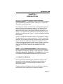
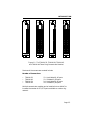
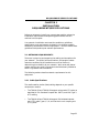
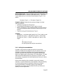
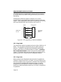
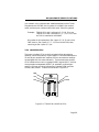
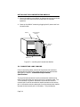
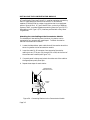
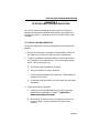
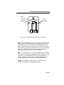
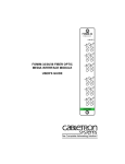
TRMIM-22/24/42/44 TOKEN RING MEDIA INTERFACE MODULES INSTALLATION GUIDE CABLETRON SYSTEMS, P.O. Box 5005, Rochester, NH 03867-0505 NOTICE NOTICE Cabletron Systems reserves the right to make changes in specifications and other information contained in this document without prior notice. The reader should in all cases consult Cabletron Systems to determine whether any such changes have been made. The hardware, firmware, or software described in this manual is subject to change without notice. IN NO EVENT SHALL CABLETRON SYSTEMS BE LIABLE FOR ANY INCIDENTAL, INDIRECT, SPECIAL, OR CONSEQUENTIAL DAMAGES WHATSOEVER (INCLUDING BUT NOT LIMITED TO LOST PROFITS) ARISING OUT OF OR RELATED TO THIS MANUAL OR THE INFORMATION CONTAINED IN IT, EVEN IF CABLETRON SYSTEMS HAS BEEN ADVISED OF, KNOWN, OR SHOULD HAVE KNOWN, THE POSSIBILITY OF SUCH DAMAGES. Copyright October 1992 by: Cabletron Systems, Inc. P.O. Box 5005 Rochester, NH 03867-0505 All Rights Reserved Printed in the United States of America Order Number: 9030257-02 October 92 FNB, Multi Media Access Center, Remote LANVIEW and LANVIEW are registered trademarks of Cabletron Systems, Inc. TRRMIM-A, TRRMIM-2A, TRRMIM-4A, TRMIM-22, TRMIM-24, TRMIM-42, TRMIM-44, Flexible Network Bus and MMAC are trademarks of Cabletron Systems, Inc. IBM is a registered trademark of International Business Machines Corporation. i FCC NOTICE FCC NOTICE This device complies with Part 15 of FCC rules. Operation is subject to the following two conditions: (1) this device may not cause harmful interference, and (2) this device must accept any interference received, including interference that may cause undesired operation. NOTE: This equipment has been tested and found to comply with the limits for a Class A digital device, pursuant to Part 15 of FCC Rules. These limits are designed to provide reasonable protection against harmful interference when the equipment is operated in a commercial environment. This equipment uses, generates, and can radiate radio frequency energy and if not installed in accordance with the operator’s manual, may cause harmful interference to radio communications. Operation of this equipment in a residential area is likely to cause interference in which case the user will be required at his own expense to correct the interference. If this equipment does cause interference to radio or television, which can be determined by turning the equipment off and on, the user is encouraged to try to correct the interference by one or more of the following measures: • • • • Re-orient the receiving antenna. Relocate the equipment with respect to the receiving antenna. Move the equipment away from the receiver. Plug the equipment into a different outlet so that the equipment and the receiver are on different branch circuits. If necessary, the user should consult the dealer or an experienced radio/ television technician for additional suggestions. The user may find the following booklet prepared by the Federal Communication Commission helpful: “Interference Handbook” This booklet is available from the U.S. Government Printing Office, Washington D.C. 20402 - Stock No. 004-000-00482-5. ii INTRODUCTION CHAPTER 1 INTRODUCTION Welcome to the Token Ring Media Interface Modules Installation Guide. This manual serves as a reference for installing and troubleshooting Cabletron Systems TRMIM-22 , TRMIM-24 , TRMIM-42 , and TRMIM-44 . The TRMIM-22, TRMIM-24, TRMIM-42, and TRMIM-44 comprise a family of Token Ring Concentrator modules. The TRMIM-22 and TRMIM-24 provide 12 and 24 trunk coupling unit (TCU) ports, respectively, that support voice grade unshielded twisted pair (UTP) cabling. The TRMIM-42 and TRMIM-44 have 12 and 24 TCU ports, respectively, supporting IBM type 1, 2, 6, and 9 shielded twisted pair (STP) cabling. Both UTP concentrator modules and both STP concentrator modules are equipped with RJ-45 modular connectors. The STP concentrator module RJ-45 connectors provide for connection of the cabling shield. All four concentrator modules are designed for installation in any Cabletron Systems Multi Media Access Center (MMAC ) equipped with a Flexible Network Bus (FNB). All four concentrator modules are IEEE 802.5 compliant and compatible with IBM products. NOTE: The term Concentrator Module is used throughout this manual when describing features and functions that are common to the TRMIM-22, TRMIM-24, TRMIM-42, and TRMIM-44. The terms TRMIM-22, TRMIM-24, TRMIM-42, and TRMIM-44 are used when it is necessary to describe features that are unique to any device. 1.1 USING THIS MANUAL Prior to installing and operating your concentrator module, read through this manual completely to familiarize yourself with its contents and to gain an understanding of the features of the concentrator module. A general working knowledge of Token Ring (IEEE 802.5) networks will be helpful when installing your concentrator module. Page 1-1 INTRODUCTION Chapter 1, Introduction, describes how to use this document, provides an overview of the features and capabilities of each concentrator module, and concludes with a list of related manuals. Chapter 2, Installation Requirements/Specifications, lists the network requirements that must be met before you begin installing your concentrator module. Detailed specifications for each of the concentrator modules is also provided. Chapter 3, Installing the Concentrator Module, contains instructions for installing a concentrator module into the MMAC, and attaching token ring station cabling. Chapter 4, Testing and Troubleshooting, describes checks that you can perform if you encounter problems after installing a concentrator module. Instructions for using LANVIEW, Cabletron Systems’ built-in visual diagnostic and status monitoring system, are also included. 1.2 THE CONCENTRATOR MODULES The TRMIM-22, TRMIM-24, TRMIM-42, and TRMIM-44, shown in Figure 1-1, can be installed as a free standing token ring network or to provide UTP or STP connectivity to an existing token ring network. All four concentrator modules are designed for installation into a Cabletron Systems MMAC. Since they do not have externally accessible Ring-In and Ring-Out ports, they are considered concentrator modules. (A concentrator in token ring applications is defined as a device with multiple TCU ports bounded by externally accessible Ring-In and Ring-Out ports.) All four concentrator modules are designed for installation into a Cabletron Systems MMAC, where they can be used to create an independent 12 or 24 port ring or to expand an existing token ring network. When any concentrator module is used within an MMAC, the concentrator module is connected through the MMAC backplane via the Flexible Network Bus (FNB) to other token ring MIMs, repeaters, bridges, or management modules. The MIMs automatically attach to each other through the FNB when positioned in adjacent slots and configured with identical ring speed settings. Page 1-2 INTRODUCTION TRMIM-22 TRMIM-24 SN TRMIM-44 TRMIM-42 SN SN SN 1 X 13 X 1 X 2 X 14 X 2 X 1 X 13 X 1 X 2 X 14 X 3 X 15 X 2 X 3 X 3 X 15 X 4 X 16 X 3 X 4 X 4 X 16 X 5 X 4 X 17 X 5 X 5 X 17 X 5 X 6 X 18 X 6 X 6 X 18 X 6 X 7 X 19 X 7 X 7 X 19 X 7 X 8 X 20 X 8 X 8 X 20 X 8 X 9 X 21 X 9 X 9 X 21 X 9 X 10 X 22 X 10 X 10 X 22 X 10 X 11 X 23 X 11 X 11 X 23 X 11 X 12 X 24 X 12 X 12 X 24 X 12 X UTP TOKEN RING UTP TOKEN RING STP TOKEN RING STP TOKEN RING Figure 1-1. The TRMIM-22, TRMIM-24, TRMIM-42, and TRMIM-44 Token Ring Concentrator Modules Features of the concentrator module include: Number of Connections • • • • TRMIM-22 TRMIM-42 TRMIM-24 TRMIM-44 12 - Unshielded RJ-45 ports 12 - Shielded RJ-45 ports 24 - Unshielded RJ-45 ports 24 - Shielded RJ-45 ports Multiple concentrator modules can be installed into an MMAC to increase the number of UTP/STP ports available on a token ring network. Page 1-3 INTRODUCTION Multiple Concentrator Modules Several concentrator modules can be installed into a single MMAC and configured as independent rings or linked together into a single ring network. Configuration guidelines can be found in Chapter 3, Installing the Concentrator Module. Multiple MMACs in a Ring Network Several MMACs can be connected into the same ring network by installing token ring concentrators (TRMIM-10R/20R with externally accessible Ring-In/Ring-Out ports) or token ring repeaters (TRRMIM-A/2A/4A). The choice between using concentrators or repeaters depends on specific network configurations. Refer to Cabletron Systems TRMIM-10R/20R Installation Guide or TRRMIM-A/2A/4A Installation Guide for more information on the use of these products or contact Cabletron Systems Technical Support. A variety of network management tools can be used to control and monitor these repeaters, including Cabletron Systems Local Management, Remote LANVIEW/Windows, and SPECTRUM. LANVIEW LEDs Several LEDs, on the front panel of the concentrator module, are used to indicate the ring speed, a bypass condition, status, and management statistics for each of the TCU ports. LANVIEW is an effective tool to help you quickly diagnose your physical layer network problems. Page 1-4 INTRODUCTION 1.3 RELATED MANUALS The manuals listed below should be used to supplement the procedures and other technical data provided in this manual. The procedures in them will be referenced, where appropriate, but will not be repeated. Cabletron Systems Multi Media Access Center Overview and Set Up Guide Cabletron Systems TRRMIM-A, TRRMIM-2A, & TRRMIM-4A Token Ring Repeaters Installation Guide Cabletron Systems TRMIM-10R STP Token Ring Concentrator Installation Guide Cabletron Systems TRMIM-12 Token Ring Media Interface Module Installation Guide 1.4 RECOMMENDED READING The following publications are recommended if more information is required on implementing a token ring network. Local Area Networks, Token Ring Access Method, IEEE Standard 802.5 (1989) Commercial Building Wiring Standard, EIA Standard Proposal No. 1907-B (if approved, to be published as EIA/TIA-568) LAN Troubleshooting Handbook, Mark Miller (1989, M&T Publishing) Page 1-5 INTRODUCTION 1.5 GETTING HELP If you need additional support related to the Cabletron Systems Token Ring products, or if you have any questions, comments or suggestions related to this manual, contact Cabletron Systems Technical Support at: Cabletron Systems P. O. Box 5005 Rochester, NH 03867-0505 Phone: (603) 332-9400 Page 1-6 REQUIREMENTS/SPECIFICATIONS CHAPTER 2 INSTALLATION REQUIREMENTS/SPECIFICATIONS Before you attempt to install your concentrator module, review the installation requirements and operating specifications that are outlined in this chapter. Your network installation must meet the conditions, guidelines, specifications, and requirements included in this chapter to obtain satisfactory performance from this equipment. Failure to follow these guidelines could produce poor network performance. 2.1 NETWORK REQUIREMENTS Take care in planning and preparing the cabling and connections for your network. The quality of the connections, the length of cables and other conditions of the installation are critical factors in determining the reliability of your network. Work area wall plates/ outlets used for your token ring network should be clearly labeled as token ring network lobe connections. The following sections describe network requirements for this equipment. 2.1.1 Cable Specifications The media used for station (lobe) cabling depends on your specific concentrator module: • The TRMIM-22 and TRMIM-24 support voice grade UTP cable, as described in EIA Standard Proposal No. 1907-A, and IBM Type 3 UTP cabling. • The TRMIM-42 and TRMIM-44 support IBM shielded twisted pair (STP) cable Types 1, 2, 6, and 9 at their trunk coupling unit (TCU) ports. Page 2-1 REQUIREMENTS/SPECIFICATIONS UTP CABLE TYPES Both UTP concentrator modules (TRMIM-22 & 24) support D-inside wiring (DIW) voice grade Unshielded Twisted Pair (UTP) cable as described in EIA SP-1907B. Voice grade UTP cabling (e.g., IBM Type 3 UTP) must conform to the limits shown in Table 2-1. The increased popularity and cost advantages of UTP cable have driven refinements to UTP cable design. As a result, better grades of UTP cable, known as supergrade or level 4, that exhibit improved transmission characteristics are becoming available. These improved grades of UTP can often be used to permit operation at 16 Mbit/s on longer lobe cables. Table 2-1. UTP Voice Grade (IBM Type 3) Specifications Frequency 1 Mhz 4 Mhz 10 Mhz 16 Mhz Impedance 100Ω 100Ω 100Ω 100Ω ±15% ±15% ±15% ±15% Attenuation <26 dB/km (8 dB/1000 ft) <56 dB/km (16 dB/1000 ft) <98 dB/km (30 dB/1000 ft) <131 dB/km (40 dB/1000 ft) NOTE: IBM Type 3 - Consists of four Unshielded Twisted Pairs of 24 AWG solid wire for data or voice communication and is typically used to wire cable runs within the walls of buildings. In some installations, existing UTP building wiring can be used for token ring cabling. DO NOT connect UTP cabling to any non-token ring network conductors (telephone, etc.) or ground. If in doubt, test wiring before using. WARNING: Telephone Battery and Ringing voltages, used in UTP telephone circuits, could present a shock hazard and can damage token ring equipment when connected to token ring cabling. Type 3 Media Filter When connecting token ring devices that are not equipped with a Type 3 Media Filter to either of the active UTP concentrator modules (TRMIM-22/24), a Type 3 Media Filter, such as the Cabletron Systems TRMF (see Figure 2-1) or TRMF-2, must be installed in line with the lobe cable at the connection to token ring station. Page 2-2 REQUIREMENTS/SPECIFICATIONS STP CABLE TYPES TRMF 802.5 MEDIA FILTER WITH LANVIEW SN Figure 2-1. Cabletron Systems TRMF Both STP (TRMIM-42 & 44) concentrator modules support IBM Type 1, 2, 6, and 9 STP cabling as described in Table 2-2. STP cabling must conform to the limits shown in Table 2-3. Table 2-2. IBM Cable Types Type 1 Two shielded twisted pairs (STP) of 22 AWG solid wire for data. Used for the longest cable runs within the walls of buildings. Type 2 Similar to Type 1 data cable, but having four additional unshielded twisted pairs of 22 AWG solid wire. These are carried outside of the shield casing and are typically used for voice communication. Frequently used to wire cable runs within the walls of buildings. Type 6 Two STP of 26 AWG stranded wire for data. This type is used in patch panels or to connect devices to/from wall jacks. Attenuation for Type 6 cable is 3/2 x Type 1 cable (66 m of Type 6 = 100 meters of Type 1). Type 9 Similar to Type 1, but uses 26 AWG solid wire. Attenuation for Type 9 cable is 3/2 x Type 1 cable (66 m of Type 9 = 100 meters of Type 1). Page 2-3 REQUIREMENTS/SPECIFICATIONS Attenuation and Impedance The maximum attenuation for specific STP cable types is shown in Table 2-3. The attenuation values include the attenuation of the cables, connectors, patch panels, and reflection losses due to impedance mismatches in the segment. Table 2-3. STP Cable Specifications Frequency Impedance Types 1 & 2 4 Mhz 16 Mhz Types 6 & 9 4 Mhz 16 Mhz Attenuation 150Ω ±15% 150Ω ±15% <22 dB/km (6.7 dB/1000 ft) <45 dB/km (13.7 dB/1000 ft) 150Ω ±15% 150Ω ±15% <33 dB/km (10 dB/1000 ft) <66 dB/km (20 dB/1000 ft) Cable Lengths to Stations The physical length of the cable connecting a station to the trunk coupling unit (TCU) port on the concentrator module is referred to as lobe length. The maximum lobe length attainable, under ideal conditions, with the concentrator module is shown in Table 2-4. Cable routing, connector attenuation, noise and crosstalk can adversely influence the maximum lobe length. Table 2-4. Maximum Lobe Length Cable Type Maximum Lobe Length 4 Mbit/s 16 Mbit/s TRRMIM-22/24 Voice Grade UTP (or IBM Type 3) TRRMIM-42/44 STP (IBM Types 1 & 2) STP (IBM Type 6 &9) (only for station to wall jack and patch panels) Page 2-4 200 meters 100 meters (656 feet) (328 feet) 300 meters 150 meters (984 feet) (492 feet) 200 meters (656 feet) 100 meters (328 feet) REQUIREMENTS/SPECIFICATIONS Mixed Cable Types - If you mix cable types in your installation, you must compensate for the different cable attenuations. Type 6 and Type 9 cables can be run for only 2/3 the distance of Type 1. This means: 10 meters (Type 1) ≈ 6.6 meters (Types 6, 9) Sample Problem: Determine the maximum length for mixed cabling installation — 16 Mbit/s ring speed and 130 stations. — The building has 60 meters of Type 1 cable in the wall. — What is the length of Type 6 cable available to connect from the TCU port to the patch panel and from the local wall jack to the station? — Type 6 can only go 2/3 the distance of Type 1. Solution: 100 meters = maximum cable length if only Type 1 cable is used [60 meters of Type 1] + [40 meters of Type 1] = max. length [60 meters of Type 1] + [(0.66) x (40 meters) of Type 6] = max. length | | 26.4 meters of Type 6 (for patch panel and wall jack connections) 2.1.2 Cabling Recommendations Crosstalk, noise, and the number and quality of connections determine reliable data propagation and your network’s error rate. Crosstalk is interference caused by signal coupling between the different cable pairs contained within a multi-pair cable bundle. Multi-pair cables should not be used for UTP lobe cabling. STP lobe cabling should be dedicated to carrying token ring traffic. Avoid mixing token ring signals with other applications (voice, etc.) within the same cable. Noise can be caused by either crosstalk or externally induced impulses. If noise induced errors are suspected, it may be necessary to re-route cabling away from potential noise sources (motors, switching equipment, fluorescent lighting, high amperage equipment), or to ensure that the electrical wiring in the area is properly wired and grounded. Page 2-5 REQUIREMENTS/SPECIFICATIONS In addition to complying with the preceding cable specifications, the following recommendations should be followed to minimize errors and help to obtain optimum performance from your network: • UTP cabling should be free of splices, stubs or bridged taps. • No more than two punch-down blocks between TCU ports and wall outlets. • Metal troughs, ducts, etc. carrying token ring signals should be properly grounded. • Route cables away from sources of electrical noise, such as: - Power lines - Fluorescent lights - Electric motors - Radio interference - Heavy machinery. • Do not use UTP as main trunk cabling. • Token ring signals should not be routed through UTP cables that exit a building or which are adjacent to cables either exiting a building or exposed to lightning strikes and power surges. • UTP cables that contain token ring signals should not be simultaneously used for applications which may impress high voltages (greater than 5 volts) with sharp rise or fall times, since the noise coupling from such signals could directly cause errors on the token ring network. • For single telecommunications closet rings, lobe lengths should not exceed 100 meters or 22 to 24 AWG wire from the attaching device and the TCU port. • When possible, use dedicated UTP cable for token ring signals. Page 2-6 REQUIREMENTS/SPECIFICATIONS 2.2 MAXIMUM NUMBER OF STATIONS The maximum number of stations in a single ring, using STP lobe cabling is dependent on the ring speed. At 4 Mbit/s, up to 250 stations can be connected. At 16 Mbit/s, up to 136 stations can be connected. When UTP lobe cabling is used anywhere on the ring, the number of stations is limited to 72 stations, regardless of the ring speed. 2.3 OPERATING SPECIFICATIONS This section describes the operating specifications for each of the active token ring concentrator modules. Cabletron Systems reserves the right to change these specifications at any time without notice. 2.3.1 Connector Types The concentrator module TCU ports are internally crossed-over to provide connection of station lobe cabling via female RJ-45 receptacles on the front panel. Figure 2-2 shows the pinouts required for the mating (male) RJ-45 connectors for both UTP and STP versions of the concentrator modules. The RJ-45 connectors (male and female) used with the TRMIM-42 and TRMIM-44 are encased in a metallic shield that is connected to the cable shield. Trunk Coupling Unit (TCU) Port TX+ RX– RX+ TX– 8 7 6 5 4 3 2 1 MALE RJ-45 TX+ RX– RX+ TX– 8 7 6 5 4 3 2 1 Cable Shield MALE RJ-45 Cable Shield Figure 2-2. Concentrator Module TCU Port Pinouts Page 2-7 REQUIREMENTS/SPECIFICATIONS The shield continuity is maintained by contacts within the female RJ-45 that contact the metallic casing of the male RJ-45 on the STP lobe cabling. Shielded patch cables that adapt a shielded RJ-45 to a Data Connector (MIC) are available from Cabletron Systems in eight foot lengths. These adapter/patch cables permit connecting to an existing patch panel equipped with data connectors (see Figure 2-3). Data Connector (MIC) Shield RJ-45 TX+ TRMIM-42/44 TCU Port TX– 6 3 Orange Black O TX+ B TX– R RX+ RX– RX+ 4 Red RX– 5 Green G Shield Shield Patch Panel/ Token Ring Station Figure 2-3. STP Adapter/Patch Cable (PN 9420002) 2.3.2 Ring Speed The concentrator module ring speed can be set to either 4 Mbit/s or 16 Mbit/s. The ring speed is automatically set to a default setting at power on. The default ring speed can be selected by positioning a network speed jumper on the board (Refer to Chapter 3, Installing the Concentrator Module, to learn how to set the network speed jumper.) The default setting can be overridden by changing the ring speed through local or remote network management software. 2.3.3 Ring Order When multiple Token Ring boards (set to the same ring speed) are installed in adjacent slots within an MMAC, they can be attached via the FNB to create a larger ring network. Multiple Token Ring boards are automatically attached (when possible) at power on, but the configuration can be modified via network management software, attaching or detaching adjacent boards and, as a result, changing the ring sequence. Page 2-8 REQUIREMENTS/SPECIFICATIONS In a network using a concentrator module attached to other Token Ring boards via the FNB, the ring order is in MMAC slot number order, and then port number order within each Token Ring board. Example: TRMIM-22 in slot 1 with ports 2, 5, 8, & 12 in use. TRMIM-22 in slot 2 with ports 1, 5, 7, 11, & 12 in use. An FNB is installed in the MMAC. Ring order for this example is Slot 1 ports 2, 5, 8, 12, out to the FNB, then to Slot 2 ports 1, 5, 7, 11, 12 out to the FNB; then, returning to Slot 1 ports 2, 5, etc. 2.3.4 LANVIEW LEDs There are a number LEDs on the front panel of the concentrator modules. While the quantity of port-specific LEDs differ between the 12 and 24 port concentrator modules, all four concentrator modules are equipped with the same indicators. Three concentrator-specific LEDs indicate the current ring speed (16MB), bypass (BYP), and the current mode, management (MGMT) or automatic, and two portspecific LEDs per port that indicate Port Enabled (PEN) and Port Linked (LNK) status. These are illustrated in Figure 2-4. 16MB LNK PEN TRMIM-24 SN MGMT PEN LNK LNK PEN 13 14 15 16 17 18 19 20 21 22 23 24 13 X BYP 16MB BYP MGMT 1 2 3 4 5 6 7 8 9 10 11 12 1X Figure 2-4. TRMIM-24 LANVIEW LEDs Page 2-9 REQUIREMENTS/SPECIFICATIONS 16MB - Ring Speed LED (Yellow) is lit to indicate that the concentrator module ring speed is set to 16 Mbit/s. When this indicator is not lit, the ring speed is set to 4 Mbit/s. BYP - Error (Yellow), when lit, indicates that the module is in bypass mode. PEN - Port Enabled (Yellow - 12 or 24), when lit, indicates that the associated port is enabled by network management. LNK - Link Status (Green - 12 or 24), when lit, indicates that the associated station is providing phantom current. MGMT - Management (Green) when lit, indicates that the concentrator module is in Management Mode. Settings are stored by the management module in slot 0. 2.3.5 General Specifications SAFETY WARNING: It is the responsibility of the person who sells the system to which the TRMIM-22/TRMIM-24/TRMIM-42/TRMIM-44 will be a part to ensure that the total system meets allowed limits of conducted and radiated emissions. This equipment is designed in accordance with UL478, UL910, NEC 725-2(b), CSA, IEC, TUV, VDE Class A, and meets FCC Part 15, Class A limits. SERVICE TRMIM-22/42 MTBF (MHBK-217E) MTTR Page 2-10 TBD <0.5 hr. TRMIM-24/44 TBD <0.5 hr. REQUIREMENTS/SPECIFICATIONS PHYSICAL Dimensions (includes front panel) 13.4D x 11.5H x 2.0W inches (34.0D x 29.2H x 5.1W centimeters) Weight 2 lbs. 2 oz. (963.9 grams) Page 2-11 INSTALLING THE CONCENTRATOR MODULE CHAPTER 3 INSTALLING THE CONCENTRATOR MODULE This chapter contains instructions for installing your concentrator module into a Cabletron Systems MMAC product and connecting token ring stations at the concentrator module’s trunk coupling unit (TCU) ports. Check that all requirements listed in Chapter 2, Installation Requirements/Specifications, have been met before installing and operating the concentrator module. When you install your concentrator module, the following guidelines will help you to properly configure your system: • The concentrator module cannot be installed into the rightmost slot, Slot 0. Slot 0 is reserved for specific management/bridging/ repeater modules. • When the concentrator module is being installed into an MMAC-8 or MMAC-8FNB, be sure that a PSM or PSM-R is installed in the associated rear power supply slot. The PSM or PSM-R, Power Supply Module is the source of power for MMAC modules. One Power Supply Module is required for every two MIMs. NOTE: The PSM-R (Redundant Power Supply Module) is recommended for use with the MMAC-8FNB (with a Flexible Network Bus). • Multiple token ring products, within an MMAC, are automatically linked at power on, provided that the following conditions are met: - The MMAC must be configured with an FNB, (either an MMAC-3FNB, MMAC-5, or an MMAC-8FNB). Without the FNB, the individual MIMs will not be linked, but will form independent Token Ring networks. Page 3-1 INSTALLING THE CONCENTRATOR MODULE NOTE: The FNB is a full-height, full-width backplane that links Cabletron Systems Token Ring products. MMAC-3s and MMAC-8s (without an FNB) can be upgraded with an FNB, providing greater flexibility in configuring your system. Contact Cabletron Systems Technical Support for more information. • - The boards being linked must be arranged sequentially in adjacent MMAC slots, e.g., slots 2, 3, and 4. - To link Token Ring boards, the boards must be set to the same ring speed. Token Ring boards operating at different ring speeds (4 Mbit/s and 16 Mbit/s) cannot be attached into the same ring network. Linking boards set to different ring speeds requires the use of a bridging device. To establish a network path between a token ring network and another network type (i.e., FDDI or Ethernet) requires the use of a bridging device. 3.1 UNPACKING THE CONCENTRATOR MODULE Prior to installation, unpack and visually inspect your concentrator module for damage: CAUTION: Electrostatic Discharge (ESD) can damage your concentrator module. Observe all precautions to prevent electrostatic discharges and when handling the concentrator module. Hold only the edges of the board or the metal front panel. Avoid touching the components or surface of the board. 1. Carefully remove the concentrator module from the shipping box. Save the box and materials for possible future repackaging and shipment. 2. Remove the concentrator module from its protective plastic bag and set it on top of its protective bag in a static free area. This will help to prevent ESD damage. Contact Cabletron Systems Technical Support immediately if you encounter any problems unpacking or installing your concentrator. Page 3-2 INSTALLING THE CONCENTRATOR MODULE 3.2 CONFIGURING THE CONCENTRATOR MODULE 1. Position the hardware jumper on the proper pins on the concentrator module to select either 4 or 16 Mbit/s as the default network ring speed (see Figure 3-1). The speed setting is a factor in determining the maximum lobe length. Refer to Chapter 2, Installation Requirements/Specifications for additional information. NOTE: The network speed is also selectable by software. The software selection overrides the hardware jumper selection. 12/24 RJ-45 TCU Port Connectors 4 Mbit/sec 16 Mbit/sec ... J1 J1 Network Speed Jumper Mother board Daughter board Front Panel Figure 3-1. Network Speed Jumper 3.3 INSTALLING THE CONCENTRATOR MODULE INTO THE MMAC Install the concentrator module into the MMAC as follows: 1. If it is not already powered off, power off the MMAC chassis by unplugging the AC power cord from the wall outlet. 2. Remove the selected blank panel from the MMAC and slide the concentrator module into the MMAC card cage (see Figure 3-2). Be sure that the card is in the card guides at the top and bottom slots of the card cage. NOTE: The module may be “Hot Swapped” when servicing. Page 3-3 INSTALLING THE CONCENTRATOR MODULE 3. Secure the module to the MMAC by tightening the knurled knobs. Failure to firmly secure the MIM may result in improper operation. 4. Power on the MMAC chassis by plugging the AC power cord into the wall outlet. MMAC-8 CONCENTRATOR MODULE IRM TRMIM-22 KNURLED KNOBS UTP TOKEN RING BOARD SLOT Figure 3-2. Installing the Concentrator Module 3.4 CONNECTING LOBE CABLING Prior to connecting cables, check that the pinouts and maximum cable lengths throughout the system conform to the requirements described in Chapter 2, Installation Requirements/ Specifications. The physical lobe connection from the concentrator module to the token ring station does not require the use of a crossover cable. The TCU and token ring station connectors are wired such that the transmit pair from the concentrator module connects to the receive pair in the station and the receive pair from the concentrator module connects to the transmit pair in the station. This provides the Page 3-4 INSTALLING THE CONCENTRATOR MODULE necessary signal crossover or null modem effect. Table 3-1 provides a cross-reference of pinouts for connections that may be encountered along the length of lobe cabling. Table 3-1. Connector Pinout Cross-reference Signal Name TX+ TX– RX+ RX– RJ-11 6-pin modular connector RJ-45 8-pin modular connector 5 2 3 4 6 3 4 5 Data Connector (MIC) connector DB-9 9-pin D-shell genderless O (Orange) B (Black) R (Red) G (Green) 9 5 1 6 The lobe cabling used with the TRMIM-42/44 requires shielded RJ-45 connections to attain the maximum lobe lengths listed in Chapter 2, Installation Requirements/Specifications. Shielded patch cables that adapt a shielded RJ-45 to a Data Connector (MIC) are available from Cabletron Systems. These adapter/patch cables permit connecting to an existing patch panel equipped with data connectors (see Figure 3-3). Lobe Cable RX+ 6 6 RX– 3 3 TX+ TX– 9 TX+ 5 TX– 1 RX+ 6 RX– Token Ring Station TX+ 4 4 TX– 5 5 RX+ RX– DB-9 RJ-45 Token Ring Station UTP Lobe Cable RX+ RX– 6 3 6 3 TX+ 4 4 TX– 5 5 TX+ TX+ TX– TX– RX+ RX+ RX– RX– 6 9 TX+ 3 5 TX– 1 RX+ 6 RX– 4 5 TYPE 3 MEDIA FILTER RJ-45 DB-9 Figure 3-3. Token Ring Station Cabling Page 3-5 INSTALLING THE CONCENTRATOR MODULE A Type 3 Media Filter (see Figure 2-1), must be used when connecting the UTP lobe cable from either of the active UTP concentrator modules (TRMIM-22/24) to a token ring station that is not equipped with an internal filter. A Type 3 Media Filter, such as the Cabletron Systems TRMF, provides impedance matching from the Type 3 (UTP) lobe cabling to the Type 1 (STP) interface provided with many token ring stations. Attaching the Lobe Cabling at the Concentrator Module The twisted pair lobe cabling from the token ring station can be connected to any concentrator module port. To attach the station cable at the concentrator module: 1. Locate the lobe cable or patch cable that will be used to attach the token ring station to the concentrator module. 2. Insert the male RJ-45 connector from one end of the station cabling into any TCU port (1X through 12X or 24X) at the front of the concentrator module (see Figure 3-4). 3. If a patch panel is being used, attach the other end of the cable to the appropriate patch panel jack. 4. Repeat these steps for each station. CONCENTRATOR MODULE RJ-45 PORT 23 X 24 X STATION CABLE UTP TOKEN RING RJ-45 CONNECTOR Figure 3-4. Connecting Stations to the Concentrator Module Page 3-6 INSTALLING THE CONCENTRATOR MODULE Attaching the Lobe Cable at the Station Connect the stations to the concentrator module using a Type 3 patch cable. Attach one end of the patch cable at the wall plate and the other to the station port (see Figure 3-4). NOTE: A Type 3 Media Filter must be installed at the station end of the lobe cable when connecting UTP lobe cabling between an active UTP concentrator module and a token ring station without an internal filter. 3.5 FINISHING THE INSTALLATION With power on at the MMAC and the attached stations, the green Link Attached LEDs on the MIM should be illuminated for each station that is inserted into the ring. The yellow 16MB LED should only be on if the concentrator module is set for 16 Mbit/s ring speed. If these conditions do not exist, proceed to Chapter 4, Testing and Troubleshooting. The concentrator is now ready for operation. Before placing the network into service, test the installation thoroughly to be sure that all stations are able to be addressed and that the data is being relayed without error. Verify that the networking software is configured properly to match the installed network. Page 3-7 TESTING AND TROUBLESHOOTING CHAPTER 4 TESTING AND TROUBLESHOOTING This section contains procedures to verify that the connections between the concentrator module and the token ring stations are functioning properly. A description of the LANVIEW LEDs is also provided. 4.1 INSTALLATION CHECKOUT Perform the following to check the installation of the concentrator module: 1. Be sure that the token ring stations and the MMAC match the AC power source (120 Vac or 240 Vac) and are powered on. 2. Trace the ring path through the network, to be sure that there are no breaks in the ring and that it is free from logical design errors. While tracing the ring: a. Check each cable connection at the MIM. b. Verify the pinouts for every connection. c. Check the cable conductors for continuity. Cable testers are available for this task. d. Check that cable connections at patch panels and wall plates are secure. 3. Check the network ring speed: a. Verify that the ring speed matches the station and cable specifications mentioned in Chapter 2, Installation Requirements/Specifications. b. Be sure that all devices in the ring network are set to the same ring speed. Check all MIMs and stations in the network. Page 4-1 TESTING AND TROUBLESHOOTING c. Check that the MIMs in the MMAC are grouped together according to network type and data rate. For example, Ethernet MIMs together, 4 Mbit/s token ring MIMs together, and 16 Mbit/s token ring MIMs together. 4. Ensure that the maximum cable length for EACH station and the maximum number of stations are not exceeded. When these checks have been successfully completed for each connection, the concentrator module is ready for normal operation. If further problems occur, contact Cabletron Systems Technical Support. 4.2 USING LANVIEW LANVIEW is Cabletron Systems’ built-in visual diagnostic and status monitoring system. Using LANVIEW, your network troubleshooting personnel can quickly scan the LANVIEW LEDs to determine network status, diagnose network problems, and isolate faulty nodes or trunk segments. The LANVIEW LED locations are shown in Figure 4-1. While the TRMIM-24 is shown in the illustration, the locations and definitions apply to all four concentrator modules, except that for the TRMIM-22 and TRMIM-42, ports 13 through 24 and the LEDs associated with them are not present. • 16MB - The Ring Speed LED (Yellow) is lit to indicate that the concentrator module ring speed is set to 16 Mbit/s. When this indicator is not lit, the ring speed is set to 4 Mbit/s. The ring speed is set to a default setting by hardware jumper, J1 (refer to Chapter 3, Installing the Concentrator Module, for setting this jumper). The concentrator module is set to the default ring speed at power on. The ring speed can be changed via network management software. • BYP - The error indicator (Red) should not be lit under normal operating conditions. When lit this LED indicates the detection of a concentrator module hardware failure. If the problem persists, contact Cabletron Systems Technical Support. Page 4-2 TESTING AND TROUBLESHOOTING 16MB LNK PEN TRMIM-24 SN MGMT PEN LNK LNK PEN 13 14 15 16 17 18 19 20 21 22 23 24 13 X BYP 16MB BYP MGMT 1 2 3 4 5 6 7 8 9 10 11 12 1X Figure 4-1. Concentrator Module LANVIEW LEDs • PEN - Port Enabled Status (Yellow - 12 or 24) indicates that the associated port is enabled by network management. A port that is enabled is set to permit insertion of the attached token ring station. When both the PEN and LNK LED are lit for the same port, the token ring station attached to that TCU port is inserted on the ring. When this LED is not lit, the associated port is disabled and insertion onto the ring is inhibited. • LNK - Link Status (Green - 12 or 24) provides a visual indication of phantom current from the associated token ring station. When this LED is lit, the associated station is providing phantom current. When this LED is not lit, the associated station has removed phantom current from the TCU port connection. • MGMT - Management (Green) when lit, indicates that the concentrator module is in Management Mode. Page 4-3