1
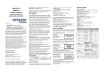
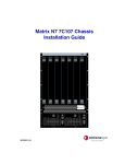
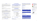
SAFETY INFORMATION
NOTICE
CLASS 1 LASER TRANSCEIVERS
Enterasys Networks reserves the right to make changes in specifications and other information contained
in this document and its web site without prior notice. The reader should in all cases consult Enterasys
Networks to determine whether any such changes have been made.
THE XENPAK 10GBASE-LR, 10GBASE-ER, 10GBASE-LX4, AND
10GBASE-SR USE CLASS 1 LASER TRANSCEIVERS. READ THE
FOLLOWING SAFETY INFORMATION BEFORE INSTALLING OR
OPERATING THESE PHYS.
The hardware, firmware, or software described in this manual is subject to change without notice.
IN NO EVENT SHALL Enterasys Networks BE LIABLE FOR ANY INCIDENTAL, INDIRECT,
SPECIAL, OR CONSEQUENTIAL DAMAGES WHATSOEVER (INCLUDING BUT NOT LIMITED
TO LOST PROFITS) ARISING OUT OF OR RELATED TO THIS DOCUMENT, WEB SITE, OR THE
INFORMATION CONTAINED IN THEM, EVEN IF Enterasys Networks HAS BEEN ADVISED OF,
KNEW OF, OR SHOULD HAVE KNOWN OF, THE POSSIBILITY OF SUCH DAMAGES.
Enterasys Networks, Inc.
50 Minuteman Road
Andover, MA 01810
©2003 Enterasys Networks, Inc. All Rights Reserved.
Part Number: 9033836-02 August 2003
The Class 1 laser transceivers use an optical feedback loop to maintain Class 1 operation limits. This
control loop eliminates the need for maintenance checks or adjustments. The output is factory set, and
does not allow any user adjustment. Class 1 Laser transceivers comply with the following safety
standards:
FCC NOTICE
This device complies with Part 15 of the FCC rules. Operation is subject to the following two conditions:
(1) this device may not cause harmful interference, and (2) this device must accept any interference
received, including interference that may cause undesired operation.
NOTE: This equipment has been tested and found to comply with the limits for a class A digital device,
pursuant to Part 15 of the FCC rules. These limits are designed to provide reasonable protection against
harmful interference when the equipment is operated in a commercial environment. This equipment uses,
generates, and can radiate radio frequency energy and if not installed in accordance with the operator’s
manual, may cause harmful interference to radio communications. Operation of this equipment in a
residential area is likely to cause interference in which case the user will be required to correct the
interference at his own expense.
WARNING: Changes or modifications made to this device which are not expressly approved by the
party responsible for compliance could void the user’s authority to operate the equipment.
Ports
•
CENELEC EN 60825 (European Committee for Electrotechnical Standardization).
1 10-Gbps Port
To prevent electrostatic damage, observe the following guidelines:
Wear an anti-static wrist strap connected to a suitable earth ground whenever handling
the module.
Store or transport this module only in appropriate anti-static packaging.
Do not remove the PHY from its packaging until you are ready to
install it.
Do not touch any of the PHY’s pins, connectors or components.
Hold the PHY only by its edges or faceplate.
•
•
•
•
•
Physical Dimensions
Size: 11.33 cm H x 3.48 W x 1.17 D (4.46 in. H x 1.37 W x 0.46 D)
Weight: 0.13 kg (0.29 lbs)
Optics
Equipment Checklist
When the connector is in place, all laser radiation remains within the fiber. The maximum amount of
radiant power exiting the fiber (under normal conditions) is -12.6 dBm or 55 x 10-6 watts.
Xenpak PHY
Extinction
Ratio
Received
Sensitivity
Link Budget
Removing the optical connector from the transceiver allows laser radiation to emit directly from the
optical port. The maximum radiance from the optical port (under worst case conditions) is 0.8 W cm-2 or
8 x 10³ W m2 sr-1.
Output
Power
10GBASE-LR
<0.5 dBm
>4 dB
-10.28 dBm
0 to 9.4 dB
10GBASE-ER
<4.0 dBm
>3 dB
-10.3 dBm
5 to 11 dB
Tools
10GBASE-LX4
<0.5 dBm
>3.5 dB
-10.3 dBm
0 to 7.5 dB
This installation requires the following tools:
-13.4 dBm
(on 10µm fiber)
0 to 8.2 dB
(on 10µm fiber)
-11.1 dBm
7.3 dB
Do not use optical instruments to view the laser output. The use of optical instruments to view laser
output increases eye hazard. When viewing the output optical port, power must be removed from
the network adapter.
DECLARATION OF CONFORMITY
Application of Council Directive(s):
Manufacturer’s Name:
Manufacturer’s Address:
European Representative Address:
This digital apparatus does not exceed the class A limits for radio noise emissions from digital apparatus
set out in the Radio Interference Regulations of the Canadian Department of Communications.
Le présent appareil numérique n’émet pas de bruits radioélectriques dépassant les limites applicables aux
appareils numériques de la class A prescrites dans le Règlement sur le brouillage radioélectrique édicté
par le ministère des Communications du Canada.
Conformance to Directive(s)/
Product Standards:
VCCI NOTICE
This is a class A product based on the standard of the Voluntary Control Council for Interference by
Information Technology Equipment (VCCI). If this equipment is used in a domestic environment, radio
disturbance may arise. When such trouble occurs, the user may be required to take corrective actions.
Equipment Type/Environment:
89/336/EEC
73/23/EEC
Enterasys Networks, Inc.
50 Minuteman Road
Andover, MA 01810
Enterasys Networks Ltd.
Nexus House, Newbury Business Park
London Road, Newbury
Berkshire RG14 2PZ, England
EC Directive 89/336/EEC
EC Directive 73/23/EEC
EN 55022
EN 55024
EN 60950
EN 60825
Networking Equipment, for use in a
Commercial or Light Industrial Environment.
Enterasys Networks, Inc. declares that the equipment packaged with this notice conforms to the above
directives.
AGENCY STANDARDS
Safety
CLASS A ITE NOTICE
CAUTION: Xenpak PHYs are easily damaged by electrostatic
discharge.
E9.1.2.0 or later
IEC Publication 825 (International Electrotechnical Commission).
INDUSTRY CANADA NOTICE
WARNING: This is a class A product. In a domestic environment this product may cause radio
interference in which case the user may be required to take adequate measures.
ELECTRICAL HAZARD: Only qualified personnel should perform
installation procedures.
Firmware Requirements
21 CFR 1040.10 and 1040.11 U.S. Department of Health and Human Services (FDA).
SAFETY INFORMATION
CLASS 1 LASER TRANSCEIVERS
LASER RADIATION AND CONNECTORS
WARNING: The XENPAK PHYs use Class 1 Lasers. Do not use
optical instruments to view laser output. The use of optical
instruments to view laser output increases eye hazard.
Handling the PHY
SPECIFICATIONS
•
When operating within their performance limitations, laser transceiver output meets the Class 1
accessible emission limit of all three standards. Class 1 levels of laser radiation are not considered
hazardous.
INSTALLING THE PHY
The LAN XENPAK PHYs (physical interfaces) provide inexpensive, high-speed Ethernet
connectivity. These PHYs provide network managers the ability to use 10-Gigabit
Ethernet technologies to provide high-speed, local backbone interconnections between
large capacity switches. As demand for bandwidth increases, network administrators can
deploy 10-Gigabit Ethernet throughout the entire network to improve server farm,
backbone, and campus-wide connectivity.
•
LANVIEW is a registered trademark of Enterasys Networks. ENTERASYS NETWORKS, NETSIGHT,
MATRIX, WEBVIEW, and any logos associated therewith, are trademarks or registered trademarks of
Enterasys Networks, Inc.
All other product names mentioned in this document may be trademarks or registered trademarks of their
respective companies.
XENPAK 10GBASE-LR, -ER, -LX4, AND -SR PHYS
Meets the requirements of UL 60950, CSA C22.2 No. 60950, 73/23/EEC, EN 60950, IEC 60950, EN
60825, 21 CFR 1040.10.
Electromagnetic Compatibility
10GBASE-SR
<-1 dBm
>3 dB
After unpacking the PHY, check the contents of the box to be sure you received the
following items:
One Xenpak PHY in anti-static bag
•
Anti-static Wrist Strap
Temperature
Operating: 41° to 104° F (5° to 40° C)
Storage: -22° to 164° F (-30° to 73° C)
Hot Swap
Humidity
To hot swap a Xenpak PHY, do not press the hot swap button. You may remove or install a
PHY at any time.
5% to 90% (non-condensing)
CONNECTIVITY GUIDELINES
Table 1
Recommended Cable Types and Specifications
Xenpak PHY
Type
Max. Length
Connector
10GBASE-LR
SMF
10 km (6.21 mi)
SC
10GBASE-ER
SMF
40 km (24.85 mi)
SC
10GBASE-LX4
SMF
MMF
10 km (6.21 mi)
300 m (984.25 ft)
SC
10GBASE-SR
62.5 um MMF 200Mhz/km
50 um MMF 400Mhz/km
50 um MMF 2000Mhz/km
33 m (108 ft)
66 m (217 ft)
300 m (884 ft)
SC
SC
SC
NOTE: The 10GBASE-ER Xenpak requires a minimum of 5dB attenuation or a
cable length of about 10 km.
Compliant with the requirements of FCC Part 15, CSA C108.8, 89/336/EEC, EN 55022, EN 61000-3-2,
EN 61000-3-3, EN 55024, AS/NZS 3548, and VCCI V-3.
1
2
TROUBLESHOOTING
Instructions
CAUTION: Before performing any upgrade or installation, ensure
that you are properly “grounded” to avoid electrostatic discharge.
1.
2.
3.
4.
Attach the anti-static wrist strap (refer to the instructions in the anti-static wrist strap
package) and remove the PHY from its anti-static packaging.
Position the PHY with its top side oriented as shown below and its edge connector
facing the port slot.
Carefully push the PHY into the slot until the back of the PHY’s faceplate is flush with
the faceplate of the receiving module.
Tighten the two thumbscrews to secure the PHY to the module. This completes the
installation.
Installing a Xenpak PHY
Common Errors
•
•
•
•
The PHY is not seated properly.
Tx and Rx connections are not matched correctly.
The PHYs used on either end of the connection are not identical.
The 10GBASE-ER Xenpak requires a minimum of 5dB attenuation or a cable length
of about 10 km.
ADDITIONAL INFORMATION
For additional information about installing Xenpak PHYs, visit the Enterasys Networks
web site.
Xenpak 10GBASE-LR, -ER,
-LX4, and -SR PHYs
Getting Help
Tx
For additional support related to the Common CLI syntax or this document, contact
Enterasys Networks using one of the following methods:
World Wide Web
http://www.enterasys.com/
Phone
603-332-9400
1-800-872-8440 (toll-free in U.S. and Canada)
Quick Start
For the Enterasys Networks Support toll-free
number in your country:
http://www.enterasys.com/support/gtac-all.html
Rx/Link
Internet mail
[email protected]
Additional documentation
http://www.enterasys.com/support/manuals
Web Site: http://www.enterasys.com/
To send comments or suggestions concerning this document, contact the
Technical Writing Department via the following email address:
[email protected]
Please include the document Part Number in the email message.
9033836-02
Before contacting Enterasys Networks for technical support, have
the following information ready:
•
•
•
•
•
•
3
Your Enterasys Networks service contract number
A description of the failure
A description of any action(s) taken to resolve the problem (e.g., changing mode
switches, rebooting the unit)
The serial and revision numbers of all involved Enterasys Networks products in the
network
A description of your network environment (layout, cable type, etc.)
Network load and frame size at the time of trouble (if known)
4
5