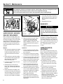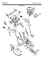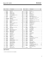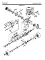
1
®
OWNER’S MANUAL
Snow Thrower
SAFETY FIRST!
Before operating this equipment, read this
Owner’s Manual and the separate manual
supplied by the engine manufacturer.
•
•
•
•
•
•
Safety
Assembly
Features and Controls
Operation
Maintenance
Parts List
Models
42051 - 9.5HP / 26" Auger
42052 - 11 HP / 30" Auger
(11HP Model shown)
GARDEN WAY INCORPORATED
Table of Contents
Dear Owner:
Thank you for purchasing this product. The unit was carefully designed and manufactured to provide excellent
performance if properly operated and maintained.
Review this manual frequently to familiarize yourself with
the unit, its features and its safe operation. Be sure that
you and any other operators carefully follow the recommended safety practices at all times. Failure to do so
could result in personal injury or property damage. This
Manual is considered a permanent part of the unit and it
must stay with the unit if the unit is resold.
The warranty statement is included in the literature package. Read it carefully. Also, please complete and return
the postpaid owner registration card included with this
Manual. The purpose of the card is to register each unit
and owner at the factory to provide product updates.
If you have any problems or questions concerning the unit,
contact your local authorized dealer or the Factory (see
back page of this Manual).
We want to ensure your complete satisfaction at all times.
See Back Cover for
Customer Service Information
Safety Alert Symbol
This is a safety alert symbol. It is used in this manual
and on the unit to alert you to potential hazards. When
you see this symbol, read and obey the message that
follows it. Failure to obey safety messages could
result in personal injury or property damage.
WARNING
The engine exhaust from this product contains chemicals known to the State of California to cause cancer,
birth defects or other reproductive harm.
This machine meets voluntary safety standard B71.3 – 1995,
which is sponsored by the Outdoor Power Equipment
Institute, Inc., and is published by the American National
Standards Institute.
2
SECTION 1: SAFETY ........................................... 3
Safety Decals ......................................................................... 5
SECTION 2: ASSEMBLY ....................................... 6
Inspect Unit............................................................................. 6
Unpack Unit ............................................................................ 6
Hardware Bag Contents........................................................... 6
Remove (optional) Drift Slicers ............................................... 6
Install Handlebars ................................................................... 7
Install Discharge Chute ........................................................... 7
Attach Chute Control Rod........................................................ 8
Attach Auger Drive Control Rod .............................................. 8
Attach Wheel Control Rod ....................................................... 8
Attach Gear Shift Control Rod ................................................. 8
Connect Wiring for Handlebar Warmers and Light.................. 10
Add Motor Oil to Crankcase .................................................... 10
Check Auger Gear Case Oil Level............................................. 10
Check Tire Pressure ................................................................ 10
Install Drift Slicers................................................................... 10
SECTION 3: FEATURES AND CONTROLS...................... 11
SECTION 4: OPERATION ....................................... 12
Pre-Operation Checklist........................................................... 12
Starting the Engine.................................................................. 13
Stopping ................................................................................. 13
Auger Drive Engagement......................................................... 14
Wheel Drive Engagement ........................................................ 14
Auger Drive/Wheel Drive Interlock Feature.............................. 14
Shifting Gears ......................................................................... 14
Transporting the Unit .............................................................. 14
Snow Throwing Tips ............................................................... 14
Snow Throwing Patterns......................................................... 15
SECTION 5: MAINTENANCE ................................... 16
Engine Maintenance ................................................................ 16
Lubrication .............................................................................. 16
Wheel Drive Disc Adjustment.................................................. 16
Auger Drive Belt and Wheel Drive Belt Replacement ............. 18
Shear Bolts.............................................................................. 18
Auger Drive Belt(s) Adjustment............................................... 18
Gear Shift Rod Adjustment ................................................ 19
Drive Disc Clearance Adjustment ............................................ 19
Brake Arm Adjustment ............................................................ 19
Skid Shoes/Scraper Blade ....................................................... 20
Slip Differential Adjustment..................................................... 20
Off-Season Storage ................................................................. 20
Troubleshooting Chart ............................................................ 21
Required Maintenance Schedule ............................................. 23
SPECIFICATIONS/KITS & ACCESSORIES ..................... 24
PARTS LIST ...................................................... 25
CUSTOMER SERVICE INFORMATION .............. BACK COVER
Section
1 Safety
Gear Shift Lever
SPARK ARRESTER WARNING TO RESIDENTS
OF CALIFORNIA AND SEVERAL OTHER STATES
Under California law, and under the laws of several other states,
you are not permitted to operate an internal combustion engine
using hydrocarbon fuels on any forest, brush, hay, grain, or
grass covered land; or land covered by any flammable agricultural crop without an engine spark arrester in continuous effective working order.
The engine on the unit is an internal combustion engine which
burns gasoline, a hydrocarbon fuel, and must be equipped with a
spark arrester muffler in continuous effective working order. The
spark arrester must be attached to the engine exhaust system in
such a manner that flames or heat from the system will not ignite
flammable material. Failure of the owner/operator of the unit to
comply with this regulation is a misdemeanor under California
law (and other states) and may also be a violation of other state
and/or federal regulations, laws, ordinances or codes. Contact
your local fire marshal or forest service for specific information
about which regulations apply in your area.
Training
1. Read this Owner’s
Manual and the separate Engine Owner’s
Manual carefully before operating the
unit. Be completely familiar with the
controls and the proper use of the
unit. Know how to stop the unit and
disengage the controls quickly. A replacement manual is available by contacting the factory.
2. Never allow children to operate the
unit. Never allow adults to operate
the unit without proper instruction.
3. Keep the area of operation clear of
all persons, particularly small children
and pets. Keep bystanders at least 25
feet away from the area of operation.
4. Exercise caution to avoid slipping or
falling, especially when operating in
reverse.
5. Familiarize yourself with all of the
safety and operating decals on the
unit and on any attachments or
accessories.
6. Do not run the engine in an enclosed
area. Engine exhaust contains carbon
monoxide gas, a deadly poison that is
odorless, colorless, and tasteless. Do
not operate the unit near buildings,
windows, or air conditioners.
Chute Directional Control
Auger Drive Control Lever
Wheel Drive
Control Lever
Discharge Chute
Chute Deflector Cap
Collector
(auger/impeller)
Housing
Auger Assembly
7. Keep hands or any other part of the
body or clothing away from the inside
of the collector (auger/impeller) housing, the discharge chute opening, or
moving parts.
8. Do not operate the unit if you are
under the influence of alcohol, medication, or when tired or ill.
Preparation
1. Wear approved safety glasses or eye
shields during operation or while performing an adjustment or repair to
protect eyes from foreign objects that
may be thrown from the unit.
2. Do not wear loose-fitting clothing,
such as scarves, which could be
caught by moving parts. Tie up or restrain long hair.
3. Before starting the engine, check the
tightness of all screws, nuts, bolts,
and other fasteners. Replace or clean
any damaged or unreadable safety
and operating labels.
4. Wear adequate winter outer garments
when operating the unit. Wear
footwear that will improve footing on
slippery surfaces.
5. Use extra care when handling gasoline
or other fuels. Gasoline and its vapors
are highly flammable and explosive.
To help prevent a fire or explosion:
Skid Shoe
a. Store gasoline only in an approved
gasoline storage container, safely
out of the reach of children.
b. Never remove the fuel fill cap on
the fuel tank, or add fuel while the
engine is running or hot.
c. Keep matches, smoking materials,
open flames, and sparks away from
the fuel tank and gasoline storage
container.
d. Fill the fuel tank outdoors and with
extreme care. Never fill the fuel
tank indoors.
e. Replace the fuel fill cap on the fuel
tank, the cap on the gasoline storage container, and clean up fuel
spills before starting the engine.
f. Leave 1-1/2 inch (3.81 cm) of air
space at the top of the fuel tank to
allow for fuel expansion.
g. Do not store unit or gasoline storage container where there is a danger of an open flame or spark, or
where ignition sources are present
such as hot water and space
heaters, furnaces, clothes dryers,
stoves, electric motors, etc.
6. For units equipped with electric-start:
a. Only use a 3-pronged, UL rated and
approved, outdoor use power cord.
Do not use any adapters on the
cord.
3
Section 1: Safety
b. The 120V A.C. starter is equipped
with a three-wire power cord and
plug and is designed to operate on
120V A.C. household current. The
starter must be properly grounded
at all times to avoid the possibility
of injury or death from electrical
shock. Determine that your house
wiring is a Ground Fault Interrupted
(G.F.I.) three-wire grounded system, or ask a licensed electrician if
you are not sure. If your house
wiring system is not a G.F.I. threewire grounded system, DO NOT use
the electric starter under any condition. If your house wiring system is
grounded but a G.F.I. three-prong
wall receptacle is not available at
the location your starter will be
used, one should be installed by a
licensed electrician.
c. Inspect the power cord for damage
before use. If it is damaged, do not
use it.
d. Stand on dry ground when handling
the power cord. Do not handle the
power cord with wet hands or wet
gloves. Do not use the electric
starter if it is raining.
e. Connect the cord to the electric
starter first, and then plug the cord
into a properly grounded outlet
(this lessens the chances of sparks
from occurring near the engine).
f. Do not abuse the power cord. Do
not pull the unit by the cord. Do not
pull the cord to disconnect it from
the outlet. Keep the cord away
from sharp edges, oil, and excessive heat.
g. Store the power cord in a secure
place, safely out of the reach of
children.
7. Adjust the skid shoes and scraper
blade so the collector (auger/impeller)
housing clears gravel or crushed rock
surfaces.
8. Never attempt to make any adjustments while the engine is running
(except when specifically recommended by the the manufacturer).
4
Operation
1. The operator of the unit is responsible
for the safety of all persons in the operating zone of the unit.
2. Before starting the unit, disconnect
the spark plug wire and check the collector (auger/impeller) housing and
discharge chute to make sure they are
free of ice.
3. Disengage all clutches before starting
the engine.
4. Let the unit adjust to outdoor temperature before use.
5. Check the operation of the controls
before using the unit. Do not operate
the unit unless all controls are operating properly.
6. Never carry passengers on the unit.
They could fall off and be seriously injured, or they could interfere with safe
operation.
11. Stop the engine and disconnect the
spark plug wire whenever you leave
the operating position, before unclogging the collector (auger/impeller)
housing or discharge chute, and when
making any repairs, adjustments, or
inspections. Use only a wooden stick
(at least 3 feet long) to clear away any
blockage.
12. When cleaning, repairing, or inspecting, make certain the auger, impeller
and all moving parts have stopped.
Disconnect the spark plug wire from
the spark plug and secure the wire
away from the spark plug.
13. Keep all guards, covers, shields and
safety devices in place and in good
working condition. Do not attempt to
defeat the purpose of any safety
device.
14. Exercise extreme caution on slopes.
15. Do not attempt to clear steep slopes.
16. Do not clear snow across the face of
slopes. Exercise extreme caution
when changing direction on slopes.
7. Keep hands, other body parts, and
clothing away from any moving or rotating parts. Keep clear of the intake
and discharge openings at all times.
8. Before starting the engine, inspect the
area where the unit is to be used and
remove all sleds, boards, doormats,
wire, bottles, cans, or other debris.
9. Keep children out of the area of operation and under the watchful eye of an
adult not operating the unit. Never assume that children will remain where
you last saw them.
10. If the unit makes an unusual noise or
vibration, immediately shut the engine
off, wait for all moving parts to stop,
disconnect the spark plug wire from
the spark plug and perform the following steps:
a. Inspect for damage.
b. Replace or repair any damaged
parts.
c. Check for and tighten any loose
parts.
17. Always observe the terrain. Watch for
and avoid obstacles. Stay away from
holes, ditches, soft or steep embankments and other potentially dangerous terrain. Deep snow can hide obstacles and drop-offs.
18. Do not use the unit near drop-offs,
ditches, or embankments. If a wheel
goes over an edge, or if an edge
caves in, the unit could overturn.
19. Never operate the unit at high transport speeds on slippery surfaces.
Wet surfaces reduce traction and
stability.
20. Look behind and use care when operating the unit in reverse. If you have
to pull the unit backward, disengage
the auger and wheel drives. Always
check behind for hazards.
21. Be extremely careful when using the
unit near blind corners, shrubs, trees,
and other objects that may obscure
vision.
Section 1: Safety
22. Be extremely careful when operating
on or crossing gravel drives, walks or
roads. Stay alert for hidden hazards
or traffic. Remove any hearing
protection.
23. Do not overload the machine capacity
by attempting to clear snow at too
fast a rate.
24. After striking a foreign object, stop
the engine, remove the wire from the
spark plug, thoroughly inspect the
unit for any damage, and repair the
damage before restarting and operating the unit.
25. Use only attachments and accessories
that are approved for use with the unit
(such as wheel weights, counterweights, cabs, and the like). Contact
an authorized dealer or the factory if
you are not sure about the use of any
attachment or accessory.
32. Disengage the auger and wheel drives
if you are approached by any child,
inattentive person or pet.
33. Run the unit for a few minutes after
use to prevent freeze-up. Remove any
snow from the unit (snow can melt,
re-freeze and jam the unit).
Maintenance and Storage
1. When the unit is stopped for servicing,
inspection, storage, or to change an
attachment or an accessory,
disconnect the spark plug wire from
the spark plug and secure the wire
away from the plug. Allow the engine
to cool before making inspections, adjustments or performing any
maintenance.
2. Maintain the unit and all attachments
and accessories in safe working
condition.
26. Operate the unit only in daylight or in
good artificial light. Always be sure of
your footing, and keep a firm hold on
the handlebars. Walk; never run.
3. Never perform any maintenance while
the engine is running, or when the
spark plug wire is connected to the
spark plug.
27. Do not tamper with the engine governor settings. The governor controls
the maximum safe engine operating
speed and protects the engine and
moving parts from damage. Contact
your local engine dealer for service if
a problem exists.
4. Do not store the unit or fuel container
inside an enclosure where there is an
open flame or spark, or where ignition
sources are present, such as: hot
water and space heaters, furnaces,
clothes dryers, stoves, electric motors,
etc.
10. Check the tightness of the auger shear
bolts and other fasteners at frequent
intervals to be sure the unit is in safe
working condition. Torque shear bolts
to 11 ft. lbs. (15 Nm).
11. Maintain or replace safety and instruction decals as needed if they are damaged or illegible.
12. Refer to the separate Engine Owner’s
Manual for complete engine operating
and maintenance information.
13. Refer to the “storage” instructions in
this Manual and in the Engine Owner’s
Manual if the unit is to be stored for an
extended period.
Safety Decals
For your personal safety and the safety of
others, a number of safety message decals
have been affixed to your unit. Keep them
clean and legible at all times. Contact your
local service dealer or the factory for replacements if any decals are damaged or
missing.
Refer to the parts listing for decal
locations, part numbers, and ordering
instructions.
28. Disengage the auger drive when the
unit is being transported or is not in
use. Disconnect the spark plug wire
from the spark plug to prevent accidental starting.
29. Do not touch the muffler or other engine parts which may be hot from operation. Wait for parts to cool completely before inspecting, cleaning or
repairing the unit.
5. Allow the engine to cool before storing
in any enclosure.
30. Never operate the unit near buildings,
glass enclosures, automobiles, window wells, drop-offs, etc., without
first properly adjusting the discharge
angle and direction. Keep children and
pets away.
7. Store gasoline only in an approved
gasoline storage container, safely out
of the reach of children.
31. Never direct discharge at persons, animals, vehicles or buildings. Never
allow anyone in front of the unit when
the engine is running.
9. Store the unit where children will not
have access to it. Always disconnect
the spark plug wire from the spark
plug to prevent accidental starting. On
units equipped with the electric starting, store the power cord in a secure
place, safely out of the reach of
children.
6. Store gasoline in a cool, well-ventilated area, safely away from any sparkor flame-producing equipment.
8. Use only original equipment replacement parts. Parts manufactured by
others could present a safety hazard
even though they may fit on the unit.
5
Section
2 Assembly
Auger Drive Control Lever
WARNING
To prevent personal injury or property
damage, do not start the engine until all
assembly steps are complete and you
have read and understand the safety and
operating instructions in this
manual.
NOTE: Left and right sides of the unit are
determined from the operator position,
facing the direction of forward travel.
A. Inspect Unit
Inspect the unit and shipping crate for
damage immediately after delivery. Contact
the carrier (trucking company) if you find
or suspect damage. Inform them of the
damage and request instructions for filing
a claim. To protect your rights, put your
claim in writing and mail a copy to the carrier within 15 days after the unit has been
delivered. Contact the Factory if you need
assistance.
Tools/Materials Required for Assembly
(1) Scissors or knife (to cut plastic ties)
(1) *5/16" wrench
(1) *3/8" wrench
(2) *7/16" wrenches
(2) *1/2" wrenches
(1) *9/16" wrench
(1) Phillips head screwdriver (medium)
(1) Needle-nosed pliers (medium)
(1) Automotive-type tire pressure gauge
(1) Funnel
(1) Clean, high-quality motor oil. Refer to
the separate Engine Owner’s Manual
for the exact oil specifications and
amount needed for your engine.
* Adjustable wrenches may be used.
IMPORTANT: Motor oil must be added to
the engine crankcase before the engine is
started. Follow the instructions in this
Section.
B. Unpack Unit
Follow these steps to unpack your unit.
1. After removing cardboard carton, remove discharge chute (O, Figure 2-4)
assembly (with attached hardware
bag) from inside cardboard sleeve.
6
Chute Directional Control
Gear Shift Lever
Light
Discharge Chute
Wheel Drive
Control Lever
Chute
Deflector Cap
Drift Slicers
(Optional)
Collector
(auger/impeller)
Housing
FULLY ASSEMBLED UNIT
Auger Assembly
Skid Shoe
2. Cut plastic ties securing handlebar
ends to chassis and remove handlebars. Remove any protective wrapping
on handlebars.
3. Cut the four plastic ties (two on auger
shaft and two on wheel axle) that secure the unit to the shipping pallet.
4. Move unit onto a clean, level surface.
The unit is heavy. To move the unit
off the shipping pallet, use caution
and obtain the help of at least one
assistant.
5. The hardware bag should contain the
following items:
Description
Engine Stop Switch Key ....................
Plastic Cable Tie ................................
Hex Hd. Flange Screw, 3/8-16 x 3/4 ..
Hex Hd. Screw, 1/4-20 x 3/4..............
Locknut, 1/4-20 ................................
Phillips Hd. Screw, #10-24 x 3/8 ......
Locknut, #10-24 ................................
Cotter Pin ..........................................
Electric Start Power Cord ..................
*Shear Bolt, 5/16-18 x 1-3/4 ............
*Locknut, 5/16-18 ............................
Qty.
1
3
4
2
2
2
2
1
1
2
2
* These are replacement parts (Figure 2-1)
that should be kept with this manual (if the
auger jams, the shear bolts are designed
to break to prevent damage to the auger
drive). See Section 5 for replacement
information.
Figure 2-1
C. Remove Drift Slicers
(if equipped)
1. Remove the four screws (B, Figure
2-2) and locknuts (two on each side)
that secure the drift slicers (A) and remove them from both sides of the collector (auger/impeller) housing.
NOTE: For shipping purposes, the drift
slicers are mounted backwards.
2. Place the drift slicers and hardware
aside. The drift slicers can be attached
after the unit is assembled (see last
step of these assembly instructions).
B
A
Figure 2-2
Section 2: Assembly
D. Install Handlebars
1. Use the four 3/8-16 x 3/4" hex flange
screws to attach the handlebars to the
sides of the chassis.
a. Install a screw in the upper mounting hole (C, Figure 2-3) on each
side. Leave screws loose enough to
allow handlebar to pivot.
b. Install a screw (D) in the lower
mounting hole on each side.
E
E
c. Using light pressure, press down on
the left side handlebar and tighten
the two screws. Repeat on the right
side.
C
2. There are four pre-installed screws
(E, Figure 2-3) on the inside of the
handlebars that secure the control
panel. Tighten each screw securely.
E. Install Discharge Chute
D
Figure 2-3
1. Remove the cardboard shield from the
discharge chute mount opening.
2. Loosen (do not remove) the left and
right-side sets of plastic shims (G,
Figure 2-4) and plastic hold-down clips
(H) on the toothed flange (J) of the discharge chute assembly. Remove and
save the remaining (front) hold-down
clip, shim and mounting hardware.
3. From either side of the unit, slide the
discharge chute onto the chute mounting flange (K, Figure 2-4), making sure
that the plastic shims (G) are above
the flange and the plastic hold-down
clips (H) are below the flange. Tighten
the clip mounting hardware securely
(if necessary, rotate the discharge
chute to the right to tighten the leftside clip).
P
N
J
M
G
L
H
K
J
(Front shim) G
K
4. Hook the front hold-down clip (H,
Figure 2-4) under the mounting flange
(K) and place the front plastic shim (G)
on top of the hold-down clip, between
the top of the flange and the toothed
chute flange. Secure with the mounting hardware previously removed.
5. Remove the plastic tie that secures the
worm gear assembly (L, Figure 2-4) to
the mounting bracket.
O
(Front holddown clip) H
Figure 2-4
7
Section 2: Assembly
6. Remove the washer and locknut from
the screw (M, Figure 2-4) in the worm
gear assembly (L). Position the worm
gear assembly on the mounting
bracket as follows:
a. Engage the worm gear threads 1/2way with the teeth on the flange of
the discharge chute base (rotate
chute as needed).
b. The length of the worm gear should
be centered with the teeth on the
flange of the discharge chute base.
c. Reinstall the washer and locknut on
the screw (M) and tighten securely.
7. Insert the flexible fins on the plastic
snow deflector (N, Figure 2-4) inside
the chute deflector cap (O). Close the
deflector cap by pulling the lever (P)
outward and moving the deflector cap
down. Release the lever to secure the
deflector cap in one of the discharge
angle selector holes.
F. Attach Chute Control Rod
1. Remove the plastic tie that secures the
auger drive control rod (AA, Figure 25) to the right handlebar. Next, remove the plastic tie that secures the
chute crank rod (short rod with plastic
swivel blocks) to the auger drive control rod.
2. Pull the chute crank rod (Z, Figure 2-5)
up through the top of the control
panel.
3. Attach the chute control rod sections
(S and U, Figure 2-5) as follows:
a. Insert the angled end of the chute
control rod, (U, Figure 2-5 inset)
into the hole in the swivel block (V)
that is attached to the end of the
chute crank rod (S).
b. Insert a cotter pin (W) through the
hole in the chute control rod (U) and
spread the ends of the cotter pin.
8
4. Position the chute control rod support
bracket (Y, Figure 2-6) against the underside of the handlebar console as
shown. Secure the bracket with the
two #10–24 x 3/8" Phillips pan head
screws and #10–24 locknuts supplied.
5. Rotate the chute control crank (Z,
Figure 2-5). The discharge chute
should turn freely, but with enough resistance to prevent free rotation of the
discharge chute during snow removal
operation. Adjust the worm gear assembly bracket (L, Figure 2-4) as necessary to prevent binding.
G. Attach Auger Drive Control Rod
1. Remove the plastic tie that secures the
auger drive control arm (AD, Figure
2-7) to the transmission shift arm
(AB).
2. The auger drive control rod (AA, Figure
2-7) has been pre-adjusted at the factory. To avoid misadjustment, do not
rotate the jam nut (AT, Figure 2-7)
while completing the following steps.
3. Hold jam nut (AT) in place with a 7/16"
wrench and use another 7/16" wrench
to thread the adjusting thimble (AS)
downward a total of 12 turns.
4. Raise Auger Drive Control Lever (X,
Figure 2-5) all the way up. Then hook
the spring (AC, Figure 2-7) at the lower
end of the auger drive control rod (AA)
into the hole in the auger drive control
arm (AD).
5. Thread the adjusting thimble (AS,
Figure 2-7) upward until it contacts the
jam nut (AT). Using two wrenches,
tighten the jam nut against the adjusting thimble.
6. Check that the spring (AC) is under the
correct amount of tension by performing Steps 2 through 5 of Auger Drive
Belt(s) Adjustment in Section 5 of this
manual.
H. Attach Wheel Drive Control Rod
1. Remove the plastic tie that secures the
wheel drive control rod (AE, Figure 27) and the gear shift control rod (AF)
to the left handlebar.
2. Hook the spring (AG, Figure 2-7) at the
lower end of the wheel drive control
rod (AE) into the hole in the wheel
drive control arm (AH). If necessary,
raise the wheel drive control arm (AH)
while attaching the spring.
3. Check that the spring (AG) is under the
correct amount of tension by performing Steps 1 through 4 of Wheel Drive
Disc Adjustment in Section 5.
4. The wheel drive control rod has been
pre-adjusted at the factory. When the
engine is started, as described in the
Operation section, you will be given a
functional check to make sure the
wheel drive control rod is properly
adjusted.
I. Attach Gear Shift Control Rod
1. Place the Gear Shift Select Lever
(T, Figure 2-5) in the No. 5 position.
2. Gently push the transmission shift arm
(AB, Figure 2-8) fully downward.
3. Align the holes in the transmission
shift arm (AB) and the lower end of the
gear shift control rod (AF). If the holes
do not align, follow the Gear Shift Rod
Adjustment procedure in Section 5.
4. Use two 1/4-20 x 3/4 hex head screws
and 1/4-20 locknuts (Figure 2-8) to
attach gear shift control rod (AF) to
transmission shift arm (AB).
Section 2: Assembly
Z
X
T
AA
Y
Figure 2-6
S
S
V
W
U
U
AF
Figure 2-5
AF
AE
AB
AA
R
Figure 2-8
AT
AS
AC
AD
AB
AG
AH
Figure 2-7
9
Section 2: Assembly
J. Connect Wiring for Handlebar
Warmers and Light
1. Gently unwind the electrical wiring harness (A, Figure 2-9) from its shipping
position and route it back toward the
right-side handlebar.
2. Without over-stretching the wiring harness, loop it up and around the handlebar as shown in Figure 2-9.
3. Connect the double-stranded black and
red wires leading from each handlebar
to the matching wires leading from the
wiring harness. The plastic connectors
can only be plugged in one way.
4. Connect the single black wire leading
from the light to the single black wire
leading from the wiring harness.
5. Remove excess slack from the wiring
harness and insert the wires into the
two wire clips shown in Figure 2-9. On
the right-side of the engine, tuck the
wire harness in between the starter box
and the side of the engine (see inset,
Figure 2-9).
6. Using the plastic wire ties (B, Figure
2-9) provided, loosely secure the
wiring harness to the handlebar.
K. Add Motor Oil to Crankcase
CAUTION
Do not start engine until engine
crankcase has been filled with motor oil.
Failure to follow this instruction will result in serious engine damage.
1. Be sure that the engine is level before
checking or adding oil.
2. Unscrew dipstick. Fill oil at the dipstick opening with fresh oil. See the
Engine Owner’s Manual for correct oil
specifications and quantity required.
Do not use SAE 10W40.
3. Wait a few minutes after filling, allowing oil to settle. Insert dipstick and
tighten securely. Remove dipstick and
check oil level. Oil level on dipstick
should always be at the “FULL” mark.
Adjust oil level as necessary. Reinsert
and tighten dipstick.
10
Connect
Single (Black)
Wires
Wire Clips
B
A
Connect Double
Stranded (Black
and Red) Wires
Tuck Wire Harness
between Starter Box
and Engine
B
B
Figure 2-9
L. Check Auger Gear Case Oil Level
The auger gear case was filled at the factory with the correct amount of SAE 90
gear oil. This level should be checked before using the unit. Refer to Lubrication
in the Maintenance section of this manual
for complete information.
D
C
M. Check Tire Pressure
Check the air pressure in both tires using
an automotive-type tire pressure gauge.
Inflate tires evenly to 8-12 psi
(55-82 kPa).
N. Install Drift Slicers (if equipped)
The drift slicers (C, Figure 2-10) are designed for use in deep snow. Their use is
optional for normal snow conditions.
NOTE: For shipping purposes, the drift
slicers are installed backward.
To install the drift slicers:
1. Position the drift slicers as shown, (C,
Figure 2-10) to the outside of the collector (auger/impeller) housing.
2. Attach the drift slicers with the four
5/16–18 x 3/4 screws and locknuts (D)
provided with the drift slicers.
D
Figure 2-10
Section
3 Features and Controls
WARNING
Before operating your machine, carefully
read and understand all safety, controls,
and operating instructions in this manual, the separate Engine Owner’s Manual
and on the decals on the machine.
Failure to follow these instructions can
result in serious personal injury.
IMPORTANT: Refer to the separate Engine
Owner’s Manual for detailed information
about the controls on the engine.
Wheel Drive Control Lever (A, Fig. 3-1)
This lever controls the engagement of the
wheel drive. When the lever is down
against the handlebar and the engine is running, the wheels will rotate. See Section 5
of this manual for adjustment information.
Auger Drive Control Lever (B, Fig. 3-1)
This lever controls the engagement of the
auger drive. When the lever is down
against the handlebar and the engine is
running, the auger (R, Figure 3-4) and
impeller (S) will rotate. See Section 5 of
this manual for adjustment information.
Gear Shift Lever (C, Fig. 3-1)
This lever controls the selection of travel
speeds: five forward and two reverse. See
Section 5 of this manual for adjustment
information.
Discharge Chute Control Rod (D, Fig. 3-1)
This lever controls the direction of the discharge chute. Approximately ten turns of
this crank moves the discharge chute all
the way from one side to the other.
Discharge Chute Deflector Cap and Lever
(E & F, Fig. 3-2)
The discharge chute deflector cap (E) controls the vertical angle of the snow discharge. To adjust the discharge angle,
move the discharge cap by pulling lever (F)
outward and moving the discharge deflector cap up or down. The discharge chute
deflector cap should usually be adjusted to
a low angle, especially in windy conditions.
Fuel Shut-Off Valve (G, Fig. 3-3)
The fuel shut-off valve controls fuel flow
from the fuel tank to the carburetor. Turn
valve 1/4 turn clockwise to OFF (closed)
position when storing or transporting unit.
Turn valve 1/4 turn counterclockwise to
ON (open) position before starting engine.
A
T
Throttle (H, Fig. 3-3)
The throttle controls the speed of the engine and is used to stop the engine.
NOTE: The engine lubrication and cooling
systems operate best at full throttle.
Primer Button (J, Fig. 3-3)
The primer button pumps small amounts
of gasoline into the engine to improve cold
weather starting.
C
D
B
Figure 3-1
F
Recoil Starter (K, Fig. 3-3)
Used for pull-starting the engine.
E
Stop Switch Key (L, Fig. 3-3)
This key-like device is used to stop the engine (the Throttle, as described above, can
also be used to stop the engine). Push the
key in before starting the engine. Pull it out
to stop the engine. Do not twist the key.
Electric Starter (M, Fig. 3-3)
The electric starter uses 120VAC house
current to start the engine. Use only the
electric cord provided with the unit to connect to house current.
Choke Knob (N, Fig. 3-3)
The choke knob controls the air/gasoline
mixture that is fed into the engine. Use
the CHOKE setting when starting the engine and the RUN setting during operation.
A warm engine may not require choking
when starting.
Skid Shoes (O, Fig. 3-4)
The skid shoes control the distance between the collector (auger/impeller) housing/scraper blade and the ground. This
distance should be adjusted to clear any
uneven or gravel surfaces. Refer to
Section 5 for adjustment information.
Scraper Blade (P, Fig. 3-4)
The scraper blade (P) clears snow close to
the pavement. Refer to Section 5 for adjustment information.
Figure 3-2
N
L
G
H
K
J
M
Figure 3-3
S
R
Light (T, Fig. 3-2)
The light is powered by the engine and
stays on during engine operation.
Handlebar Warmers
The handlebar warmers are activated when
the engine is running. The handlebar grips
will warm gradually to the touch.
Figure 3-4
O
P
R
O
11
Section
4 Operation
PRE-OPERATION CHECKLIST
Perform the following checks with the
engine stopped and the spark plug wire
disconnected from the spark plug.
1. Review Section 1: Safety and Section 3:
Features and Controls in this manual.
2. Check for loose or missing hardware.
Tighten or replace as needed.
3. Visually check inside the collector
(auger/impeller) housing and the discharge chute and remove any debris.
CAUTION
Do not start engine until engine
crankcase has been filled with oil.
Failure to follow this instruction will result in serious engine damage.
4. With the unit on level ground, check the
engine oil level according to the instructions in the engine manual. The oil
level should be at the “FULL” mark on
the dipstick.
DANGER
GASOLINE IS HIGHLY FLAMMABLE AND
ITS VAPORS ARE EXPLOSIVE.
• Follow the gasoline safety rules in this
manual (Section 1) and in the separate
Engine Owner’s Manual.
• Failure to follow gasoline safety instructions can result in serious personal injury and property damage.
5. Turn off engine and let it cool for at
least 2 minutes before removing the
gasoline fill cap. Remove the fill cap
and check the level of gasoline in the
fuel tank according to the instructions
in the engine manual.
Use fresh, clean, unleaded gasoline
(refer to engine manual for additional
gasoline information). Do not overfill
fuel tank. Fill to approximately 1-1/2
inches below top of neck to allow for
fuel expansion. DO NOT MIX OIL
WITH GASOLINE! Tighten the gasoline
fill cap securely.
6. The unit should be adjusted so the collector (auger/impeller) housing and
12
the scraper blade (A, Figure 4-1) are
1/8" above the surface to be cleared. If
clearing gravel or uneven surfaces, increase the clearance so gravel or other
foreign objects are not scooped up
into the auger.
To adjust the collector housing
height/scraper blade height:
a. Move the unit onto a level surface.
b. Loosen the four screws securing the
two skid shoes (B, Figure 4-1).
c. Adjust the skid shoes (B) until they
are in the correct position to support
the collector (auger/impeller) housing and the scraper blade (adjust
skid shoes equally to prevent uneven
snow removal).
d. Tighten the four screws.
e. The scraper blade (A, Figure 4-1)
can also be adjusted. Adjust the
scraper blade at the four carriage
bolts (C, Figure 4-1). Adjust the bottom edge of the scraper blade so it is
parallel to the bottom edge of the
auger.
7. Use the lever on the Discharge Chute
Deflector Cap (D, Figure 4-3) to adjust
the deflector cap to the desired angle
of discharge. Usually keep the angle
of the deflector cap low, especially in
windy conditions.
8. Rotate the Discharge Chute Control
Rod (E, Figure 4-3) and check for
binding. Leave the discharge chute
pointing straight ahead.
9. Check the Auger Drive and Wheel
Drive control levers (F and G, Figure 43) for freedom of movement.
10. Check the tire pressure. Inflate both
tires evenly to 8 to 12 PSI (55 to 82
Kpa).
11. Apply silicone spray on the inside of
the discharge chute, the chute discharge deflector cap, the collector
(auger/impeller) housing, and on the
augers. This will help prevent snow
from sticking (do not allow silicone
spray on rubber or plastic: damage
can result).
12. Reconnect the spark plug wire (see
engine manual) to the spark plug.
B
A
C
B
Figure 4-1
M
K
J
L
N
O
P
R
Figure 4-2
STARTING THE ENGINE
1. Complete the Pre-Operation Checklist.
Read the engine manual before starting the engine.
2. Move the unit outside to a well-ventilated, level area. Put the Gear Shift
Lever (H, Figure 4-3) into the desired
gear position. Use the slowest (1)
forward and reverse (R1) speed setting when first using the unit.
3. Rotate the Fuel Shut-Off Valve (J,
Figure 4-2) 1/4 turn counterclockwise
to the ON (open) position.
4. Move the Throttle Lever (L, Figure 4-2)
to the FAST
position.
5. Insert the Stop Switch Key (K, Figure
4-2) all the way into the switch. (The
key was included in the hardware bag
with other loose parts.)
6. Turn Choke Knob (M, Figure 4-2) to
CHOKE setting (a warm engine may
not require choking when restarting).
Section 4: Operation
7. Push the Primer Button (O, Figure 4-2)
three times (cover hole in center of
bulb when pushing).
F
E
H
G
8. To start engine with recoil starter:
a. Before pulling recoil starter (N,
Figure 4-2), be sure there are no
obstacles behind you.
D
b. Pull recoil starter handle rapidly to
overcome engine compression, prevent kick-back and start engine.
Maintain control of rope so it slowly
returns into the starter mechanism.
Repeat pulling until engine starts. If
engine fails to start, repeat starting
instructions beginning with Step 3.
c. Let engine warm up. Rotate Choke
Knob (M, Figure 4-2) toward RUN
setting a little at a time over several
seconds in warm weather, or minutes in cold weather. Let engine run
smoothly before each change.
Operate engine with choke in RUN.
d. Allow unit to adjust to outside temperature before clearing snow.
8. To start engine with electric starter:
WARNING
TO PREVENT ELECTRIC SHOCK:
• Do not use the 120VAC electric starter
in the rain.
• Do not stand in water or on damp surfaces when using the electric starter or
when connecting power cord.
• Connect the power cord only to a properly grounded, 120VAC wall outlet.
• Review electric start safety messages
in the Engine Owner’s Manual and in
Section 1 of this Manual.
a. Plug power cord supplied with unit
into the electric start switch box (R,
Figure 4-2) on the engine.
b. Plug the other end of the power
cord into a properly grounded, 3pronged 120VAC wall outlet.
IMPORTANT: To prolong starter life, use
short starting cycles (five seconds maximum, then wait one minute).
c. Push the starter button (P, Figure
4-2) on the switch box. When the
engine starts, release the button.
Figure 4-3
Disconnect power cord from wall
outlet and then from engine. (Store
power cord in a secure place, safely
out of the reach of children.) If engine fails to start, repeat starting instructions beginning with Step 3.
NOTE: The starter is thermally protected. If overheated from continuous use, it will stop automatically
and can be restarted only when it
has cooled to a safe temperature (a
wait of approximately 5-10 minutes
is required).
d. Let engine warm up. Rotate Choke
Knob (M, Figure 4-2) toward RUN
setting a little at a time over several
seconds in warm weather, or minutes in cold weather. Let engine run
smoothly before each change.
Operate engine with choke in RUN.
e. Allow unit to adjust to outside temperature before clearing snow.
STOPPING
Emergency stopping
1. Release both control levers (F and G,
Figure 4-3).
2. Move the Throttle Lever (L, Figure 4-2)
to the STOP position or pull the engine
Stop Switch key (K, Figure 4-2) out.
WARNING
Do not attempt to stop engine by moving
Choke Control to CHOKE. Backfire, fire
or engine damage could occur.
Normal (non-emergency) stopping
1. Release both control levers (F and G,
Figure 4-3). Wait for the unit to come
to a complete stop.
2. Move the Throttle Lever (L, Figure 4-2)
into the SLOW “ ” position. Allow
the engine to idle for several minutes
to melt any snow on the engine. Then
move throttle to STOP position.
3. Pull engine Stop Switch key (K, Figure
4-2) out. To prevent unauthorized use
of unit, remove key and store it in a
safe place.
4. Rotate Fuel Shut-Off Valve (J, Figure
4-2) 1/4 turn clockwise to OFF
(closed) position.
5. Disconnect the spark plug wire from
the spark plug.
6. To help prevent possible freeze-up of
controls:
a. Wipe all snow and moisture from
vicinity of controls.
b. Move Throttle Lever back and forth
several times and leave in STOP
position.
c. Rotate Choke Knob several times
and leave in CHOKE position.
13
Section 4: Operation
AUGER DRIVE ENGAGEMENT
WARNING
Stop the engine and remove the spark
plug wire from the spark plug before removing any debris from the collector
(auger/impeller) housing.
AUGER DRIVE/WHEEL DRIVE
INTERLOCK FEATURE
1. Remove any debris from inside the
collector (auger/impeller) housing.
2. Adjust the discharge chute deflector
cap (D, Figure 4-3) angle with adjustment lever. The deflector cap should
usually be adjusted to a low angle, so
it is not pointing at any persons, animals, buildings or vehicle, especially
in windy conditions.
The auger drive/wheel drive interlock feature allows the auger and the wheels to be
operated with just one hand, thus freeing
the other hand to operate the Discharge
Chute Control Rod. To engage both functions, squeeze both the Auger Drive and
the Wheel Drive levers all the way down.
Holding just the Wheel Drive Control Lever
will keep both levers down in the drive position. To disengage, release the Wheel
Drive Control Lever.
NOTE: If the auger does not start or stop
rotating as described in Steps 3 and 4
below, an adjustment is required. Refer to
Auger Drive Belt Adjustment in the
Maintenance section.
NOTE: If the Auger Drive Control Lever
does not disengage when you release the
Wheel Drive Control Lever, an adjustment
is required. Refer to Auger Drive Belt
Adjustment in the Section 5.
3. Engage the auger drive by squeezing
the Auger Drive Control Lever (F, Figure
4-3) against the handlebar. The auger
should immediately begin to rotate.
4. Disengage the auger drive by releasing
the Auger Drive Control Lever (F). The
auger should stop within five (5)
seconds.
WHEEL DRIVE ENGAGEMENT
1. Clear all obstructions from in front of
the unit.
1. Release both the auger and wheel
drive control levers (F and G, Figure 43). Wait for the unit to come to a
complete stop.
CAUTION
Transmission damage could occur if the
Gear Shift Lever is moved when the unit
is in motion. Carefully follow the shifting instructions.
2. Stand behind the unit in the operating
position.
3. Move the Gear Shift Lever (H, Figure
4-3) into the first “1” gear position.
3. Re-engage the control levers (F and G),
as required.
NOTE: If the wheels do not start or stop
rotating as described in Steps 4 and 5
below, an adjustment is required. Refer to
Wheel Drive Disc Adjustment in the
Section 5 of this manual.
NOTE: There should be full forward travel
in gear position “5” and full reverse travel
in gear position Reverse “R2”. If not, refer
to Gear Shift Rod Adjustment in Section 5.
5. Disengage the wheel drive by releasing
the Wheel Drive Control Lever. The
wheels should stop.
WARNING
Use extreme caution when operating the
unit in reverse. Clear all obstacles away
from the unit before operating in reverse. Be prepared for the unit to move
toward you when the Gear Shift Lever is
in the reverse position.
TRANSPORTING THE UNIT
Release the Auger Drive Control Lever to
disengage the auger drive whenever the
unit is being moved to and from the work
site.
The unit is extremely heavy. Have at least
one other person help you when loading
or unloading the unit into a truck or trailer.
Use ramps when loading or unloading the
unit onto a trailer or truck. Securely tie
the unit to prevent shifting while in transit.
SNOW THROWING TIPS
WARNING
SHIFTING GEARS
2. Move the Gear Shift Lever (H, Figure
4-3) into the desired position.
4. Engage wheel drive by squeezing the
Wheel Drive Control Lever (G, Figure
4-3) against the handlebar. The unit
should immediately move forward.
14
NOTE: To move the unit without throwing
snow, engage only the Wheel Drive
Control Lever.
Thoroughly inspect the area where the
unit will be used before the first snowfall. Remove all doormats, sleds,
boards, wires and other debris to prevent injury from thrown objects.
•
Remove snow as soon as possible
after a snowfall.
•
Run the engine at full throttle (the “ ”
position).
•
Apply silicone spray onto the inside of
the collector (auger/impeller) housing,
the discharge chute, the deflector cap,
and also on the augers to help prevent
snow from sticking. (Do not spray silicone on rubber or plastic: damage will
result).
•
Direct discharge downwind.
•
If a smooth area is being cleared, adjust the skid shoes so the scraper
blade is approximately 1/8" (3mm)
from the ground.
•
If a rough or gravel area is being
cleared, adjust the skid shoes so the
scraper blade clears the rough or
gravel surface.
•
Use slow travel speeds for safety and
to prevent overloading the unit.
Reverse
The two reverse settings are used to maneuver the snow thrower. Observe the
“WARNING” statement before operating
the snow thrower in reverse.
Section 4: Operation
WARNING
As you turn, rotate the
discharge chute so that
the snow is always
thrown in this direction.
➡
Do not use your hands or feet to dislodge
snow from inside the collector
(auger/impeller) housing or the discharge chute. Any contact with the
moving parts will cause serious injury.
Stop the engine and remove the spark
plug wire from the spark plug and use a
long (at least 3-feet [100CM] long)
wooden stick to unclog these areas.
SNOW THROWING PATTERNS
Use the snow clearing pattern shown in
Figure 4-4 when snow can only be thrown
to one side. Begin throwing snow closest
to the side opposite where it can be
thrown and direct the discharge away
from that side. When turning the unit
around after each pass, rotate the discharge chute as you proceed so snow
continues to be thrown in the proper
direction.
Figure 4-4
The discharge chute stays the same direction
except when turning. Snow is thrown to each side.
Use the snow clearing pattern shown in
Figure 4-5 to throw snow to both sides.
When turning the unit, rotate the discharge chute as necessary to throw snow
in the proper direction.
Figure 4-5
15
Section
5 Maintenance
WARNING
Moving parts on the unit can cause serious personal injury.
Shut off the engine, let all moving parts
stop completely, disconnect the spark
plug wire and prevent it from touching
the spark plug before performing any
maintenance or service procedures.
ENGINE MAINTENANCE
IMPORTANT: Refer to the Engine Owner’s
Manual for complete engine maintenance
information.
Engine Oil
• Check the engine oil level each time before starting the unit and after each 5
hours of operation. With the engine on
level ground, the oil level should be at
the “FULL” mark on the dipstick. Refer to
the engine manual for oil specifications
and complete instructions.
• Change the engine oil according to the
maintenance intervals and instructions in
the engine manual.
TIP: When changing engine oil, fold a
piece of cardboard or aluminum foil into a
shallow “V”, and position it so the oil will
drain through it into the container.
To check the engine oil level:
1. Move the unit to a level surface. Stop
the engine, wait for all parts to stop
moving and disconnect the spark
plug wire from the spark plug.
2. Remove the oil dipstick and wipe the
dipstick with a clean cloth.
3. Screw the oil dipstick back into the oil
fill hole. Remove the dipstick and
check the oil level – it should be up to
the “FULL” mark on the dipstick. If
low, add oil by using the oil dipstick
as a guide. Refer to engine manual
for detailed instructions.
Ignition System
The engine has an electronic ignition system which does not use points or a condenser. The spark plug is the only item requiring maintenance in this system.
16
Spark Plug
Annually or every 100 hours of operation,
remove and inspect the spark plug.
Replace the spark plug if the electrode is
pitted or burned or if the porcelain is
cracked. Refer to the engine manual for
correct spark plug specifications and servicing instructions.
NOTE: Use of an incorrect plug can damage the engine.
Carburetor
The carburetor has been adjusted at the
factory and should not require additional
adjustment. Refer to the engine manual or
contact your dealer for additional carburetor information.
LUBRICATION
At the beginning and end of each season
or after every 25 hours of operation, lubricate the unit as recommended below. The
engine must be stopped and the spark
plug wire disconnected before performing
any lubrication.
1. Lightly oil both the discharge chute
cap pivot points (A, Figure 5-1).
2. Lightly oil the discharge chute control
rod pivot points where the control rod
enters the control panel bearing (B,
Figure 5-3), the support tab (C) and the
support on the left rear of unit housing
(D, Figure 5-4).
3. Remove the left wheel (E, Figure 5-1).
Clean the wheel shaft and apply multipurpose grease to the wheel shaft.
Reinstall the wheel.
4. Apply oil to the bearings on the sides of
the auger shaft (F, Figure 5-1).
5. Clean dirt and old grease from the
flange at the bottom of the discharge
chute (G, Figure 5-1). Apply multi-purpose grease to the worm gear (H) and
to the toothed portion of flange and the
flange.
6. Lightly lubricate the handlebar control
levers at pivot points (J, Figure 5-3)
with oil or a non-silicone spray. Do
not get oil or lubricating spray on
levers.
7. Lightly oil the pivot points on the gear
shift control lever (K, Figure 5-3).
8. Remove the two shear bolts (L, Figure
5-5) from the auger shaft, then lubricate the four auger grease fittings (M,
Figure 5-5) using a grease gun. Rotate
auger three or four times. Reinstall
shear bolts, torque to 11 ft-lbs
(15Nm).
9. Check the auger gear case oil level :
a. Place the unit on a smooth, level
surface. Unscrew the plug
(N, Figure 5-5) from the front of
the gear case.
b. Inspect plug hole. Oil should just
begin to seep out of the hole. Add
SAE 90 gear oil if necessary until
oil just begins to flow out of hole.
Let the excess oil drain out of the
gear case.
c. Reinstall the plug (N).
10. Remove bolts (O, Figure 5-4) securing
bottom cover to unit. Remove bottom
cover. Put gear shift lever in highest
speed setting and apply a coating of
multi-purpose grease to the shafts (P
and R, Figure 5-2). Prevent grease
from contacting rubber drive wheel (S)
or drive disk (T). If grease should contact these parts, wipe clean to avoid
slippage and assure proper operation.
Move shift lever between high speed
and reverse settings to spread grease
along shafts. Replace bottom cover.
WHEEL DRIVE DISC
ADJUSTMENT
Due to wear, the wheel drive control disc
may begin to slip when wheel drive lever is
engaged. To adjust wheel drive disc:
1. With the engine stopped and the spark
plug wire disconnected, pull the wheel
drive control arm (V, Figure 5-4) down
completely.
2. Put the gear shift lever (AC, Figure 51) in the No. 3 position.
3. Measure and note the distance between the coiled ends of the spring
(W, Fig, 5-4).
Section 5: Maintenance
WARNING
Before inspecting, cleaning or servicing the machine, shut off engine, wait for all moving parts to come to
a complete stop, disconnect spark plug wire and move wire away from spark plug.
Failure to follow these instructions can result in serious personal injury or property damage.
X
AC
P
R
S
A
T
G
Figure 5-2
AB
J
B
K
J
E
F
Figure 5-1
H
Figure 5-3
4. Squeeze wheel drive control lever (X,
Figure 5-1) against handlebar.
Measure between the coiled ends of
the stretched spring (W, Figure 5-4),
making sure you measure between the
same coils used in step 3. The spring
length should now measure 1/2"
(13mm) longer than the measurement
taken in step 3. If it does not, loosen
jam nut (Y, Figure 5-4) and turn adjuster (Z, Figure 5-4) to increase or
decrease the spring length. (1-1/4
turns of the adjuster equals 1/16"
[1.5mm] of spring extension.) Hold
the adjuster and tighten the jam nut
(Y) when the correct spring length is
obtained. Re-check measurements
and adjust if needed.
If after completing this adjustment the
wheels do not drive adequately, refer
to Drive Disc Clearance Adjustment in
this Section. Then repeat this
adjustment.
C
D
Y
Z
V
W
O
Figure 5-4
17
Section 5: Maintenance
WARNING
Before inspecting, cleaning or servicing the machine, shut off engine, wait for all moving parts to come to
a complete stop, disconnect spark plug wire and move wire away from spark plug.
Failure to follow these instructions can result in serious personal injury or property damage.
AC
M
BA
BB
8. If the auger drive belt(s) have been replaced, then perform the Auger Drive
Belt Adjustment as described in this
section.
9. Reinstall the belt cover.
AE
AH
SHEAR BOLTS
CAUTION
AG
Figure 5-5
L
N
AF
AUGER DRIVE BELT AND WHEEL
DRIVE BELT REPLACEMENT
NOTE: The auger drive belt (there is one
auger drive belt on the 9.5HP model and
two auger drive belts on the 11HP model)
must be removed before removing the
wheel drive belt. The illustration (Figure 56) shows two auger drive belts (AD), ignore the second belt if the unit is not so
equipped.
Removal
1. With the engine stopped and the spark
plug wire disconnected, remove the
screws and washers (AB, Figure 5-1)
and remove the belt cover from the
unit.
2. Remove the two screws, flat washers
and lockwashers securing belt guide
(AC, Figure 5-6) to the engine.
Remove the belt guide.
3. Loosen jam nut (BA, Figure 5-6) and
remove bolt (BB).
4. Release tension on the idler (AF,
Figure 5-6). Remove the auger drive
belt(s) (AD) from the auger drive pulley (AE).
5. Remove the auger drive belt(s) from
the lower drive pulley (AO, Figure 5-9)
and remove belt(s) from unit. NOTE: If
you are not replacing the wheel drive
belt (AG), then proceed to Installation.
18
Figure 5-6
AO
AD
6. Remove wheel drive belt (AG, Figure
5-6) from lower drive pulley (AH).
Squeeze wheel drive control lever
against handlebar (X, Figure 5-1) to increase gap between lower pulleys as
needed.
7. Remove the wheel drive belt from unit.
Installation
1. Position wheel drive belt (AG, Figure
5-6) into lower drive pulley (AH) closest to the engine.
2. Place the belt into the groove closest
to the engine of the engine pulley (AE).
3. Position auger drive belt(s) (AD, Figure
5-6) down through gap. Position the
belt(s) into the lower drive pulley (AO).
4. Position the auger drive belt(s) (AD,
Figure 5-6) into engine pulley (AE).
5. Position belt guide (AC, Figure 5-6)
back on engine and secure with two
screws and washers removed earlier.
6. Reinstall bolt (BB, Figure 5-6), leaving
1/16" (1.5mm) clearance between underside of bolt head and front edge of
pulley (AE). Tighten jam nut (BA)
against engine crankcase.
7. If the wheel drive belt has been replaced, then perform the wheel drive
disc adjustment (see Wheel Drive Disc
Adjustment ).
Using anything but original equipment
shear bolts could result in damage to
the unit. Use factory-specified auger
shaft shear bolts when replacing shear
bolts.
Special shear bolts (L, Figure 5-5) secure
the augers to the auger shaft and are designed to break (shear) if the auger jams.
This prevents damage to other, more vital
parts. Inspect shear bolts before each use
and replace them if they are worn or broken. Torque shear bolts to 11 ft-lbs
(15 Nm).
AUGER DRIVE BELT(S)
ADJUSTMENT
Due to wear, the auger drive belt(s) may
begin to slip when the auger drive lever is
engaged. To adjust the auger drive belt(s):
1. Perform the brake arm adjustment as
described in this section. Leave the
spark plug wire disconnected while performing this adjustment.
2. If assembling a new unit, raise the
wheel drive control lever (AP, Figure
5-7) and the auger drive control lever
(AL).
3. Pull the auger drive control arm (AJ,
Figure 5-8) down completely.
4. Measure and note distance between
coiled ends of spring (AK, Figure 5-8).
5. Squeeze auger drive control lever (AL,
Figure 5-7) against handlebar. Measure
between the coiled ends of the
stretched spring (AK, Figure 5-8), making sure you measure between the
same coils used in step 4.
Section 5: Maintenance
WARNING
Before inspecting, cleaning or servicing the machine, shut off engine, wait for all moving parts to come to
a complete stop, disconnect spark plug wire and move wire away from spark plug.
Failure to follow these instructions can result in serious personal injury or property damage.
The spring length should now measure
9/16" – 11/16" (14–17mm) longer than the
measurement taken in Step 4. If it does
not, loosen the jam nut (AM, Figure 5-8)
and turn the adjuster (AN) to increase or
decrease the length of the spring. Hold
the adjuster and tighten the jam nut (AM)
when the correct spring length is obtained. Re-check the measurements and
adjust if needed.
NOTE: 1-1/4 turns of the adjuster equals
1/16" (1.5mm) of spring extension.
AL
AU
AB
AP
GEAR SHIFT ROD ADJUSTMENT
1. With the engine stopped and the spark
plug wire disconnected, move the gear
shift lever (AU, Figure 5-7) to position
No. 5. Remove the hairpin cotter and
the flat washer from the pivot block (N,
Figure 5-10). Disconnect the pivot
block (N) from the gear shift lever plate
(AV, Figure 5-10).
2. Pull the gear shift control rod (AA,
Figure 5-8) down completely.
3. While holding the gear shift control rod
(AA, Figure 5-8) down, loosen the jam
nut (ZZ, Figure 5-10) and thread the
pivot block (N) up or down as needed
so it fits into the hole in the gear shift
lever plate (AV, Figure 5-10).
4. Reinstall the pivot block (N, Figure 510) into the gear shift control lever hole
and secure with the washer and hairpin
cotter. Secure the jam nut (ZZ, Figure
5-10) against the pivot block (N).
5. Move the gear shift control lever (AU,
Figure 5-7) through the full range of
travel. Check for binding. Refer to the
Drive Disc Clearance Adjustment
instructions, if needed.
DRIVE DISC CLEARANCE
ADJUSTMENT
If the gear shift rod lever does not move
freely through all the gear positions, adjust clearance (AY, Figure 5-9) as follows:
1. With the engine stopped and the spark
plug wire disconnected, loosen jam nut
(AW, Figure 5-8). Rotate adjusting
screw (AX) until rubber drive wheel (T,
Figure 5-9) contacts metal drive disc
(U).
2. Turn the rubber drive wheel (T, Figure
5-9) and the metal drive disc (U) to
find the point of minimum clearance
(AY). (This is where both the drive
wheel [T] and metal disc [U] are
touching.)
3. Adjust the discs at the point of minimum clearance. Loosen adjusting
screw (AX, Figure 5-8) 1/2 turn.
Secure the adjusting screw (AX) in
place, while tightening the jam nut
(AW).
4. Check the clearance (AY, Figure 5-9)
by moving gear shift lever (AU, Figure
5-7) through all positions. Repeat
Step 3 as necessary.
Figure 5-7
T
AM
U
AY
AN
AW
AK
AJ
AX
AA
Q
Figure 5-8
Figure 5-9
BRAKE ARM ADJUSTMENT
The brake arm adjustment is set at the
factory to 1/16 - 1/8" for proper belt/brake
clearance. Due to wear, this may need
adjustment.
19
Section 5: Maintenance
WARNING
Before inspecting, cleaning or servicing the machine, shut off engine, wait for all moving parts to come to
a complete stop, disconnect spark plug wire and move wire away from spark plug.
Failure to follow these instructions can result in serious personal injury or property damage.
AV
C
N
E
D
ZZ
Figure 5-10
To adjust brake arm:
1. With engine stopped and spark plug
wire disconnected, remove screws and
washers (AB, Figure 5-1) and remove
belt cover from unit.
2. Squeeze the auger drive control lever
(AL, Figure 5-7) against handlebar.
3. Using a flashlight, look down through
the pulleys and belts (Figure 5-6).
Check gap between brake arm (A,
Figure 5-11) and belt (B). The gap
should measure between 1/16" and
1/8" (1.5–3 mm).
4. To adjust gap: Loosen nut (C, Figure
5-11). Hold bolt (D) in place and rotate
nut (E) until proper clearance is obtained. Secure nut (C).
5. Reinstall the belt cover.
SKID SHOES/SCRAPER BLADE
The unit should be adjusted so the collector (auger/impeller) housing and the
scraper blade (N, Figure 5-12) are 1/8" (3
mm) above the surface to be cleared. If
the unit is used to clear gravel or uneven
surfaces, this adjustment should be increased so gravel or other foreign objects
are not scooped into the auger. To adjust
the collector housing/scraper blade height:
1. Move the unit onto a level surface.
2. With the engine stopped and the spark
plug wire disconnected, loosen the
hardware securing the skid shoes (M,
Figure 5-12).
3. Adjust skid shoes until they are in the
correct position to support collector
(auger/impeller) housing and scraper
20
A
Figure 5-11
B
1/16" - 1/8"
1.5 - 3 mm
blade (adjust both skid shoes equally
to prevent uneven snow removal).
4. Tighten the hardware to lock the
skid shoes (M, Figure 5-12) into the
proper position.
5. The scraper blade (N, Figure 5-12) can
also be adjusted. Adjust scraper blade
(N) at carriage bolts. Adjust bottom
edge of scraper blade so it is parallel
with bottom edge of auger.
SLIP DIFFERENTIAL
ADJUSTMENT
1. With the engine stopped and the spark
plug wire disconnected, remove hub
cap (AQ, Figure 5-13) at end of wheel
shaft on right side of unit.
2. Remove outer (AR, Figure 5-13) and
inner jam nuts (AS) and both pairs
(four single disc springs) of disc
springs (AT). Inspect springs and replace them if they are worn.
3. Reinstall disc springs (AT, Figure 513) and inner jam nut (AS). Tighten
jam nut (AS) by hand until it contacts
the disc spring, then tighten (AS) 1 to
1-1/4 turns more. DO NOT force nut
more than 1-1/4 turns or differential
will not work (unit will be difficult to
turn).
4. Secure the inner nut (AS, Figure 5-13)
in place, while tightening the outer nut
(AR).
5. Reinstall cover (AQ, Figure 5-13).
Figure 5-12
M
N
M
OFF-SEASON STORAGE
When storing the unit for more than 90
days, follow these procedures to help keep
the unit in good condition for future use:
• Clean dirt, grime and grease from the
unit and engine.
• Perform routine lubrication as instructed earlier in this section.
• Service the engine according to the
Storage instructions in the engine
manual. Add a fuel stabilizer to the
fuel tank, according to the instructions
provided with the stabilizer. Change
the engine oil.
• On units so equipped, rotate the fuel
shut-off valve to the “OFF” position.
• Thoroughly inspect the unit for any
loose, damaged, or missing parts.
Repair or replace the parts as necessary. Check all nuts, bolts and other
fasteners for tightness and tighten as
necessary.
• Touch-up scratches and chipped paint
to prevent corrosion.
• Store the unit on a level surface, out of
the reach of children.
AQ
AT
Figure 5-13
AS AR
Section 5: Maintenance
WARNING
Before inspecting, cleaning or servicing the machine, shut off engine, wait for all moving parts to come to
a complete stop, disconnect spark plug wire and move wire away from spark plug.
Failure to follow these instructions can result in serious personal injury or property damage.
TROUBLESHOOTING
TROUBLE
Engine won’t start
POSSIBLE PROBLEM
SOLUTION
1. Choke knob in incorrect position
1. Move choke knob to CHOKE position
2. Engine throttle lever in incorrect starting position
2. Move throttle lever to correct starting
position
3. Engine not primed enough (when cold)
3. Push primer button several more times
4. Engine primed too much (when cold)
4. Put choke knob in RUN position, move
throttle lever to idle position, attempt to
start engine, then proceed with normal
starting procedure. DO NOT re-prime!
5. Spark plug wire disconnected
5. Connect spark plug wire
6. Fouled or faulty spark plug
6. Remove, clean, inspect, re-gap or
replace spark plug
7. Gasoline tank empty
7. Fill gasoline tank
8. Fuel shut-off valve is closed
8. Open fuel shut-off valve
9. Carburetor “varnished” from old gas
9. Contact authorized dealer
1. Incorrect choke knob setting
1. Put choke knob in correct setting
2. Throttle lever in incorrect position
2. Move throttle lever into FAST position
3. Fuel shut-off valve closed
3. Open fuel shut-off valve
4. Engine not primed enough
4. Push primer button several more times
5. Stale gasoline in tank
5. Drain gasoline from tank, refill with
fresh gasoline
6. Fouled or faulty spark plug
6. Remove, clean, inspect, re-gap or
replace spark plug
1. Faulty or fouled spark plug
1. Remove, clean, inspect, re-gap or
replace spark plug
2. Incorrect choke setting
2. After engine starts, gradually rotate
choke knob to RUN position
Engine overheats
1. Dirty air screen
2. Low engine oil level
3. Dirty cooling fins
4. Loose spark plug
1. Remove all debris from air screen
2. Check oil, add as necessary
3. Clean cooling fins
4. Tighten plug
Auger drive lever does not actuate
auger
1. Tension too low on spring at lower
end of auger drive control rod
2. Broken auger shear bolts
3. Loose or broken spring
4. Auger frozen
1. Increase tension on spring
Engine difficult to start
Engine idles rough
2. Replace auger shear bolts
3. Replace spring
4. Allow auger to thaw
(continued)
21
Section 5: Maintenance
WARNING
Before inspecting, cleaning or servicing the machine, shut off engine, wait for all moving parts to come to
a complete stop, disconnect spark plug wire and move wire away from spark plug.
Failure to follow these instructions can result in serious personal injury or property damage.
TROUBLESHOOTING (continued)
TROUBLE
Auger drive control lever does not
engage auger drive
POSSIBLE PROBLEM
1. Broken square key on engine drive
pulley
1. Replace key
2. Broken woodruff key on input shaft
2. Replace key
Auger spins with drive lever
disengaged
1. Tension too high on spring at lower
end of auger drive control rod
1. Decrease spring tension
Wheel drive control lever does not turn
wheels
1. Tension too low on spring at lower
end of wheel drive control rod
1. Increase spring tension
2. Broken wheel drive chain(s)
2. Replace chain(s)
3. Drive disk out of adjustment
3. Re-adjust drive disc
4. Replace wheel drive belt
4. Broken or excessively worn wheel
drive belt
5. Broken square key on engine pulley
Wheels turn with wheel drive control
lever disengaged
Snow thrower does not throw snow well
Snow thrower does not clear snow
Snow thrower makes sloping cut in snow
Electric start motor won’t crank engine
22
SOLUTION
1. Tension too high on spring at lower
end of wheel drive control rod
5. Replace key
1. Decrease spring tension
2. Drive disk out of adjustment
2. Adjust drive disc
1. Discharge chute, impeller or auger
clogged with snow, slush or ice
1. Stop engine, disconnect spark plug
wire, use a long stick to unclog
chute, auger and/or impeller
2. Snow sticks to auger or chute
2. Spray auger and chute with silicone
lubricant
3. Incorrect gear setting
3. When snow throwing, generally use
faster speeds – use slower speeds
with heavier snow
4. Loose auger drive belt(s)
4. Adjust auger drive belt(s)
1. Skid shoes set too high
1. Adjust skid shoes until scraper
blade is evenly adjusted 1/8" (3 mm)
above surface being cleared (or
higher on gravel or rough ground)
2. Scraper blade adjusted incorrectly
2. Adjust scraper blade until blade is
evenly adjusted above surface being
cleared
1. Skid shoes not set at equal height
1. Adjust skid shoes to equal height
2. Scraper blade adjusted incorrectly
2. Adjust scraper blade ends equally
1. Power cord unplugged from outlet
1. Plug power cord into outlet
2. Faulty power cord or plug
2. Replace power cord
3. Overheated starter
3. Allow starter motor to cool 5-10
minutes before trying to start
engine again
Section 5: Maintenance
WARNING
Before inspecting, cleaning or servicing the machine, shut off engine, wait for all moving parts to come to
a complete stop, disconnect spark plug wire and move wire away from spark plug.
Failure to follow these instructions can result in serious personal injury or property damage.
REQUIRED MAINTENANCE SCHEDULE
This table describes service guidelines only and does not provide complete service information. For complete service information,
contact your local authorized dealer.
Required Maintenance
Schedule
Check engine oil level
Before
Each
Use
✓ (1)
Check all hardware for tightness
✓
Check Auger Drive Lever Operation
✓
Check Wheel Drive Lever Operation
✓
After
Each
Use
Every 25
Every 50
Operating Hours Operating Hours
or Annually
or Annually
Comments
See Engine Manual
Lubricate handlebar control levers
and linkages
✓
Remove snow, slush and ice
from snow thrower
✓
Change engine oil
✓ (1)
Check tire pressure and condition
✓
Check auger gear box oil level
✓
Check belts for wear
Cooling air screen
✓
See Engine Manual
See Engine Manual
✓
Check, clean, re-gap or replace
spark plug
Apply oil to drive chains–wipe excess
Annually
✓ (2)
See Engine Manual
✓
Check belts for wear, damage,
and adjustment
✓
Adjust brake arm
✓
Grease auger
✓
Remove rust and touch-up
✓
(1) Change oil after the first two hours of operation.
(2) Annually or after every 100 operating hours.
23
Specifications, Optional Kits and Accessories
SPECIFICATIONS/OPTIONAL KITS AND ACCESSORIES
Specifications
Below is a list of specifications for your snow thrower. The information is the most current at the time this manual was printed.
Engine Model . . . . . . . . . . . . . . . . . . . . . . . . . . . . . . . . . . . . . . . . . . . . . . . . . . . . . . . . . . . .
Engine Type . . . . . . . . . . . . . . . . . . . . . . . . . . . . . . . . . . . . . . . . . . . . . . . . . . . . . . . . . . . . .
9.5HP - Briggs & Stratton
11HP - Briggs & Stratton
4-cycle, horizontal shaft
Engine Motor Oil . . . . . . . . . . . . . . . . . . . . . . . . . . . . . . . . . . . . . . . . . . . . . . . . . . . . . . . . .
Wheel Drive . . . . . . . . . . . . . . . . . . . . . . . . . . . . . . . . . . . . . . . . . . . . . . . . . . . . . . . . . . . . .
Refer to Engine Owner’s Manual
5 speeds Forward, 2 Reverse
Clearing Width . . . . . . . . . . . . . . . . . . . . . . . . . . . . . . . . . . . . . . . . . . . . . . . . . . . . . . . . . . .
9.5HP Model - 26"
11HP Model - 30"
Gear Case Oil
SAE 90-weight Gear Oil
Tire Air Pressure . . . . . . . . . . . . . . . . . . . . . . . . . . . . . . . . . . . . . . . . . . . . . . . . . . . . . . . . .
8-12 PSI (55-82 Kpa)
Optional Kits and Accessories
The items listed below are available for your snow thrower. The information is the most current available at the time this literature was
printed. To order the kits, contact your dealer or call the Factory.
Kit
Description
Tire Chain Kit . . . . . . . . . . . . . Includes tire chains for added traction.
Drift Slicer Kit . . . . . . . . . . . . . Includes drift slicers and mounting hardware
Cab Kit . . . . . . . . . . . . . . . . . . Includes three-sided protective cab, framework and hardware.
24
Parts List
Models 42051 & 42052
DRAWING NO. 1
19
18
5
1
8
2
23
3
11
4
15
14
3
16
25
24
14
13
9 22
15
12
20
6
27
22
26
8
13
17
12
7
13
13
12
Ref. #
1
2
3
4
5
6
7
8
9
11
12
13
14
15
Part #
1185224
1185374
1185841
1185431
1739790
1185842
1118726
1773207
1773170001
1735894001
1741832
1100241
1185728
1185815
12
Description
Oil Seal.........................................................1
Needle Bearing ............................................ 1
Thrust Race ................................................ 2
Roller Thrust Bearing .................................. 1
Impeller Shaft ............................................. 1
Washer........................................................ 1
Internal Retaining Ring ............................... 1
Oil Seal........................................................ 2
Flanged Cover ............................................. 1
Gear Case.................................................... 1
Hex Hd. Cap Screw, 1/4–20 x 5/8 ............... 4
Lock Washer, 1/4 ........................................ 4
Flange Bearing ............................................ 2
Thrust Race................................................. 2
(A) For Model 42051
(B) For Model 42052
Qty.
Ref. #
16
17
18
19
20
22
23
24
25
26
27
101
Part #
1720933
1720763
1100276
1741774
1105620
†
1720894
1916963
1185840
1741775
1112634
1185568
1700182
Description
Qty.
Worm Gear, 20T.......................................... 1
Spacer......................................................... 1
Woodruff Key, 1/4 x 7/8 .............................. 1
Spacer......................................................... 1
Square Head Plug, 1/4–18 NPT................... 1
Sealant ..................................................... N/I
Auger Shaft (A) ........................................... 1
Auger Shaft (B) ........................................... 1
Thrust Race................................................. 1
Spacer......................................................... 1
Welch Plug.................................................. 1
Needle Bearing ............................................ 1
Gear Lube, EP 90, 8 oz. ............................N/I
N/I Item not included with unit. Order separately.
†
Use General Electric SILMATE #RTV 1473
or equivalent. Obtain locally.
25
Parts List
Models 42051 & 42052
DRAWING NO. 2
6
99
98
113
27
13
72
14
92
1
70
64
15
71
67
91
85
102
69
90
54
82
83
45
74
48
53
34
4
5
88
10
84
62
43
31
5
1
8
4
29
77
52
44
5
67
10
65
87
49
82
86
9
97
40
84
50
50
56
44
49
12
97
56
23
42
5
7
34
35
30
26
7
95
61
68
46
16
37
20
39
68
22
41
33
11
26
100
38
68
16
81
112
36
18
111
22
17
19
62
100
96
68
16
21
16 57
16
25
32
4
79
78
3
16 49
55
57
49
58
76
26
63
34
Parts List
Models 42051 & 42052
Ref. #
1
3
4
5
6
7
8
9
10
11
12
13
14
15
16
17
18
19
20
21
22
23
25
26
27
29
30
31
32
33
34
35
36
37
38
39
40
41
42
43
44
45
46
48
49
50
Part #
1745576
1739937
1733398
1734398
1764738
1765534
1100242
1728072
1764741
1760258010
1757831010
1100044
1100255
1740030
1715716
1185506
1740011
1729440
1186334
1739935
1186329
1757841
1739838010
1186345
1764739
1186231
1757832010
1760196
1739932
1186258
1890234
1706782
1740989
1100356
1739756
1186393
1100805
1743493
1760253
1713167
1760254
1918905
1754272
1727053
1186229
1764743
Description
Qty.
Handle Grip..................................................
Idler Arm .....................................................
Lock Nut, 3/8–16 .........................................
Lock Nut, 1/4–20 .........................................
Left Control Handle......................................
Fillister-Head Bolt, 5/16–18 x 1....................
Lock Washer, 5/16.......................................
Push Nut......................................................
Wheel Drive Clutch Rod...............................
Back Plate ....................................................
Left Handlebar .............................................
Hex Hd. Screw, 5/16–18 x 3/4 .....................
Flat Washer, 5/16.........................................
Belt Cover ....................................................
Bushing .......................................................
Self-Locking Jam Nut, 3/8–16 .....................
Extension Spring .........................................
Idler Pulley ..................................................
Flange Screw, 5/16–18 x 1-3/4 ....................
Idler Arm .....................................................
Flange Screw, 5/16–18 x 3/4 .......................
Control Arm .................................................
Bottom Cover...............................................
Flange Screw, 3/8–16 x 3/4 .........................
Right Control Handle ...................................
Hex Nut, 3/8–16...........................................
Right Handlebar...........................................
Control Bracket ............................................
Control Arm .................................................
Jam Nut, 5/16–18 ........................................
Flat Washer, 1/2...........................................
Bowed Washer.............................................
S-Hook ........................................................
Cotter Pin, 3/32 x 1......................................
Cross Member .............................................
Flange Nut, 3/8–16 ......................................
Hex Hd. Cap Screw, 1/4–20 x 3/4 ................
Drive Pin, 1/8 x 3/4 ......................................
Lower Control Rod ......................................
Compression Spring ....................................
Upper Control Rod.......................................
Wiring Harness ............................................
Support Assembly .......................................
Pivot Block...................................................
Hex Nut, 1/4–20...........................................
Auger Control Rod .......................................
2
1
3
6
1
2
2
2
1
1
1
2
2
1
6
2
1
1
1
1
2
1
1
4
1
1
1
1
1
1
3
1
1
1
1
1
2
1
1
1
1
1
1
1
4
1
Ref. #
Part #
52
53
54
55
56
57
58
61
62
63
64
65
67
68
69
70
71
74
76
77
78
79
1735531
1760255
1757842
1739941
1765535
1107385
1740990
1186327
1100086
1772011
1918881
1754128
1750796
1724491
1918476
1185585
1917457
1764711
1742250
1703011
1982612
1745499
1916956
1746607
1107381
1724879
1773905
1748836
1186424
1773904
1746516
1764733
1755779
1115931
1100346
1763219
1764740
1764737
1737015
1715538
1714243
1900706
1735222
1760218
--1918428
81
82
83
84
85
86
87
88
90
91
92
95
96
97
98
99
100
102
103
104
111
112
113
Description
Qty.
Plastic tie ..................................................... 5
Shift Control Arm......................................... 1
Knob ............................................................ 1
Brake Arm.................................................... 1
Extension Spring ......................................... 2
Flat Washer, 1/2” ......................................... 2
Extension Spring ......................................... 1
Flange Screw, 5/16-18 x 1/2 ........................ 2
Hex Hd. Cap Screw, 3/8–16 x 1-3/4............. 2
Hex Hd. Cap Screw, 1/4-20 x 1.................... 1
Logo Decal................................................... 1
Thread-Forming Screw, 1/4–20 x 5/8 .......... 4
Wear Button................................................. 2
Thread-Forming Screw, 5/16–18 x 3/4 ........ 13
Console (Incl. Ref. 71)................................. 1
Flip Grommet............................................... 1
Instructions Decal........................................ 1
Shift Quadrant ............................................. 1
S-Hook ........................................................ 1
Cotter Spring ............................................... 1
Hex Hd. Screw, 3/8–16 x 2 ......................... 1
Idler Pulley (A)............................................. 1
Idler Pulley (B)............................................. 1
Plastic Tubing .............................................. 1
Flat Washer, 1/4........................................... 6
Cord Clip...................................................... 2
Bushing ....................................................... 2
Connector Body ........................................... 2
Pop Rivet, 1/8 .............................................. 2
Resistor ....................................................... 2
Clamp .......................................................... 2
Flat Spring ................................................... 1
Flange Bearing ............................................. 2
Round Head Screw, 1/4-20 x 5/8................. 4
Cotter Pin, 3/32 x 3/4................................... 2
Shoulder Bolt............................................... 1
Adjusting Nut............................................... 2
Control Rod ................................................. 1
Roll Pin, 1/8 x 5/8 ........................................ 1
Nyliner Flange Bushing ................................ 2
Flange Bearing ............................................. 2
Troy-Bilt Red Spray Paint, 13 oz. .............. N/I
Troy-Bilt Black Spray Paint, 13 oz................ N/I
Speed Control Arm ..................................... 1
Frame (see pgs. 28-29) ............................... 1
Light Kit ...................................................... 1
(A) For Model 42051
(B) For Model 42052
N/I Item not included with unit. Order separately.
27
Parts List
Models 42051 & 42052
DRAWING NO. 3
56
54
59
55
2
104
58
25
108
51
1
7
85
21
53
86
205
203
24
204
4
28
51
86
57
6
58
82
13
12
17
59
30
25
26
46
18
19
32
27
82
82
44
112
50
72
25
14
17
21
26
26
78
75
49
28
5
23
52
18
19
33
112 80
23
36
61
28
74
15
45
44
60
37
96
64
101
95
114
91
93
107
97
94
28
101
99
44
31
102
43
81
80
76
87
88
20
62
44
103
60
62
110
73
68
48
63
112
113
70
65
84 69
64
66
67
83
4
45
73
17
111
8
74
3
100
43
38
77
48
Parts List
Models 42051 & 42052
Ref. #
1
2
3
4
5
6
7
8
12
13
14
15
17
18
19
20
21
23
24
25
26
27
28
30
31
32
33
36
37
38
43
44
45
46
48
49
50
51
52
53
54
55
56
57
58
59
60
61
Part #
1100045
*
1745485
1100242
1903416
1187474
1749177
1917742
9677
1917406
1751601
1760260
1118808
0182087
1185013
1739454
1745437
1714299
1186391
1186393
1739458
1745498
1100346
1739497
--1745880
1745879
1741647
1746744
1755894
1739471
1732499
1916885
1745860
1100044
9929
1745488
1743433
1110644
1754302
1185885
1745535
1720918
1100005
1718781
1739488
1740002
1760252
Description
Qty.
Hex Hd. Screw, 5/16–18 x 1 ............................ 3
Briggs & Stratton Engine ................................. 1
Control Arm ..................................................... 1
Lock Washer, 5/16........................................... 3
Shoulder Bolt, 3/8-16 x 1-1/2 .......................... 1
Square Key, 1/4 x 2-1/4 ................................... 1
Belt Guide ........................................................ 1
Bushing............................................................ 1
Set Screw, 5/16–18 x 5/8................................. 2
Engine Sheave ................................................ 1
V-Belt .............................................................. 1
Drive Support (Incl. Ref. 110).......................... 1
Retaining Ring ................................................. 5
Offset Link (Half Link)...................................... 2
Connecting Link, #41 ....................................... 2
Final Drive Chain #40 (Requires Refs. 87 & 88) 1
Control Link ..................................................... 1
Flange Bushing ................................................ 2
Flange Lock Nut, 5/16–18 ................................ 4
Flange Lock Nut, 3/8–16 .................................. 3
Flange Bearing ................................................. 4
Sprocket Assembly, 9T/17T ............................. 1
Cotter Pin, 3/32 x 3/4....................................... 6
Support Plate ................................................... 1
Sprocket, 30T (see Ref. 99) ............................ 1
Drive Chain (Requires Refs. 18 and 19) ............ 1
Drive Chain (Requires Refs. 18 and 19) ............ 1
Compression Spring ........................................ 1
Axle Shaft ........................................................ 1
Hex Hd. Screw, 5/16–18 x 1-3/4...................... 1
Flange Bushing, 7/8 ......................................... 2
Lock Nut, 5/16–18 ........................................... 11
Hex Shaft ......................................................... 1
Shaft Support................................................... 2
Hex Cap Screw, 5/16–18 x 3/4......................... 4
Special Flat Washer.......................................... 2
Wheel Drive Sheave ......................................... 1
Ball Bearing...................................................... 2
Cap Screw, 3/8–16 x 3-1/2 .............................. 2
Drive Disc Support........................................... 1
Woodruff Key, 3/16 x 5/8................................. 1
Spindle............................................................. 1
Drive Plate ....................................................... 1
Hex Head Screw, 5/16–24 x 1.......................... 2
Shim ................................................................ A/R
Bearing Retainer .............................................. 2
Flat Washer, 7/8............................................... 4
Connecting Link ............................................... 1
Ref. #
62
63
64
65
66
67
68
69
70
72
73
74
75
76
77
78
80
81
82
83
84
85
86
87
88
91
93
94
95
96
97
99
100
101
102
103
104
107
108
110
111
112
113
114
203
204
205
Part #
1739485
1736561
1720811
1741733
1186327
1739490
1185376
9361
1720859
1709224
1720810
1772333
1745497
1185496
1758305
1739476
1185808
1745495
1714233
1705093
1107386
1745489
1745490
1185026
1120213
1756230
1746743
1756231
1746739
1758300
1716223
1758898
Description
Qty.
Bearing Retainer ..............................................
Snap Ring ........................................................
Bearing Flange .................................................
Ball Bearing......................................................
Flange Screw, 5/16–18 x 1/2 ...........................
Friction Disc Hub .............................................
Drive Pin, 3/16 x 1-1/2.....................................
Woodruff Key...................................................
Molded Friction Disc ........................................
Special Washer ................................................
Bearing Flange Assembly.................................
Lock Nut, #10–24 ............................................
Sprocket Assembly, 9T/30T .............................
Jam Nut, 1/2–13 ..............................................
Drive Pin .........................................................
Spacer..............................................................
Ball Bearing......................................................
Sprocket, 9T ....................................................
Nylon Bushing .................................................
Special Flat Washer..........................................
Flat Washer, 5/8...............................................
Spacer..............................................................
Bearing Retainer ..............................................
Connecting Link ...............................................
Offset Link (Half Link)......................................
D-Hole Drive Washer ......................................
Disc Spring .....................................................
Dust Cap .........................................................
Friction Disc ....................................................
Flange & Axle Tube Assembly .........................
Lug Bolt ..........................................................
Differential Assembly (Incl. one Ref. 31
and four ea. Refs. 44, 100, 102) ................
--Hex Hd. Bolt, 5/16-18 x 4-1/2 (see Ref. 99) .....
1745883
Nylon Bushing ................................................
--Spacer (see Ref. 99) ......................................
1758302
Axle Shaft ........................................................
1754303
Hex Head Screw, 3/8–16 x 8-1/2 .....................
1186233
Jam Nut, 1/2–13 .............................................
1754301
Tubular Spacer.................................................
1739460
Flange Bearing .................................................
1760218
Speed Control Arm .........................................
1918852010 Frame...............................................................
1757886
Wheel & Tire Assembly ...................................
1757880
Wheel & Tire Assembly ...................................
1186211
Hex Nut, 5/16-24 .............................................
1916959
Hex Hd. Cap Screw, 5/16-24 x 4-1/2................
1100255
Flat Washer, 5/16.............................................
2
1
2
1
5
1
1
1
1
1
2
8
1
1
1
2
2
1
4
1
1
1
2
1
1
1
4
1
1
1
3
1
4
2
4
1
1
2
1
2
1
1
1
1
1
1
2
*Purchase engine parts from the nearest authorized engine dealer. Refer to engine for type and code.
A/R – As Required
29
Parts List
Models 42051 & 42052
DRAWING NO. 4
69
3
2
56
47
4
51
22
70
56
7
9
62
57
9
52
22
7
7
56
57
5
53
67
54
76
12
30
66
43
1
11
47
4
47
48
15
62
13
17
35
49
73
68
46
19
68
71
50
44
6
63
58
61
60
16
58
58
59
58
31
42
32
17
14
32
74
64
38
39
27
20
21
24
23
18
35 4
25
34
36
65
10
29
26
37
72
29
33
58
27
29
28
30
29
58
45
41
40
14
26
Parts List
Models 42051 & 42052
Ref. #
1
2
3
4
5
6
7
9
10
11
12
13
14
15
16
17
18
Part #
1186329
1185403
1757843
1107383
1737499
1185984
1177625
1714782
1186391
1754424
1756141
1735869
1100044
1724870
1724885
1100255
1774145
1917463
19
20
21
22
23
24
25
26
27
1750691
1734398
1186126
1757836
1745799001
1200033
1185348
1185803
1735625
28
1918439001
1918443001
1185816
1100068
1918438001
1918442001
1186098
1758136001
1916971001
1728567010
1733398
1111599
1100053
1100245
1100257
1185846
29
30
31
32
33
34
35
36
37
38
39
40
Description
Qty.
Flange Bolt, 5/16–18 x 3/4...........................
Retainer, 3/8 ................................................
Knob ............................................................
Flat Washer, 3/8...........................................
Grip..............................................................
Flange Nut, 3/8–16 ......................................
Roll Pin, 1/8 x 3/4 ........................................
Swivel Block ................................................
Flange Nut, 5/16–18 ....................................
Crank Support .............................................
Chute Control Shaft .....................................
Gear Support ...............................................
Hex Head Cap Screw, 5/16–18 x 3/4 ...........
Worm Gear ..................................................
Drive Pin, 3/32 x 3/4 ....................................
Flat Washer, 5/16.........................................
Collector Housing Assembly
(Incl. Ref. 19) (A)......................................
Collector Housing Assembly
(Incl. Ref. 19) (B)....................................
Warning Decal .............................................
Lock Nut, 1/4–20 .........................................
Carriage Bolt, 3/8–16 x 3/4 ..........................
Chute Control Crank ....................................
Impeller Fan.................................................
HyPro Key, 3/16 x 3/4..................................
Roll Pin, 1/4 x 1-1/4.....................................
Grease Fitting...............................................
Shear Bolt Kit (Incl. one ea. shear bolt and
Ref. 58 lock nut)......................................
26" Auger, R.H. (A) ......................................
30" Auger, R.H. (B) ......................................
Special Washer, 1-1/64 ...............................
Hex Head Cap Screw, 3/8–16 x 3/4 .............
26" Auger, L.H. (A).......................................
30" Auger, L.H. (B).......................................
Carriage Bolt, 5/16–18 x 3/4 ........................
Scraper Blade (A) ........................................
Scraper Blade (B) ........................................
Skid Shoe ....................................................
Lock Nut, 3/8–16 .........................................
Hex Head Cap Screw, 1/4–20 x 5/8 .............
Hex Head Cap Screw, 1/2–13 x 3/4 .............
Lock Washer, 1/2.........................................
Flat Washer, 1/2...........................................
Flange Bearing .............................................
1
1
1
7
1
1
5
2
7
1
1
1
6
1
1
3
1
1
1
6
4
1
1
1
2
4
1
1
1
6
2
1
1
2
1
1
2
6
6
2
2
2
2
Ref. #
41
42
43
44
45
46
47
48
49
50
51
52
53
54
56
57
58
59
60
61
62
63
64
65
66
67
68
69
70
71
72
73
74
76
106
Part #
1720922
1185798
1772310
1772310
1725282
1917403
1186097
1741640
1772333
1103959
1724869
1752461
1757840010
1757824
1750692
1723643001
1185147
1737940
1732499
1185838
1737419
1752460
1714243
1737957
1754572001
1753357
1771718010
1759140
1750969
1758058
1890945
1918881
1739793
1916969
10771
1918899
1918900
1771274
97092
Description
Qty.
Bearing Support...........................................
Flange Bolt, 3/8–16 x 1/2.............................
V-Belt (A).....................................................
V-Belt (B).....................................................
Auger Sheave (A) ........................................
Auger Sheave (B).........................................
Carriage Bolt, 5/16–18 x 5/8 ........................
Ball Bearing .................................................
Lock Nut, #10–24.........................................
Flat Washer, #10..........................................
Hold-Down Clip ...........................................
Sems Screw, #10–24 x 7/8..........................
Chute Control Support .................................
Chute Crank Rod..........................................
Warning Decal .............................................
Adjusting Lever............................................
Cotter Pin, 3/32 x 1/2...................................
Truss-Head Bolt, #10–24 x 3/8 ....................
Lock Nut, 5/16–18..........................................
Flange Bearing .............................................
Set Screw, 5/16–18 x 3/4 ............................
Shim ............................................................
Nylon Bushing .............................................
Nylon Washer ..............................................
Housing Support .........................................
Sleeve ..........................................................
Discharge Chute Assembly ..........................
Discharge Cap (Incl. Ref. 53).......................
Button Plug..................................................
Spun Silver Inlay..........................................
Flat Washer, 3/8...........................................
Housing Logo Decal ....................................
Gear Case Assembly (A) ..............................
Gear Case Assembly (B) ..............................
*Drift Slicer (complete kit)...........................
Auger Width Decal (A) .................................
Auger Width Decal (B) .................................
Chute Deflector ............................................
Loctite #242, .02 oz......................................
2
2
1
2
1
1
7
1
11
6
3
6
1
1
1
1
4
5
11
2
2
4
2
2
1
1
1
1
2
1
1
1
1
1
1
1
1
1
N/I
(A) For Model 42051
(B) For Model 42052
* Drift Slicers are an optional item for Model 42051.
N/I - Item not included with unit. Order separately.
A/R - As Required
31
CUSTOMER SERVICE INFORMATION
Owner Registration Card
Please fill out and mail the enclosed owner
registration card. The purpose of this card is
to register each unit at the factory so that we
can provide you with warranty benefits and informational bulletins.
Customer Service and Technical Service
If you have questions or problems with the
unit, contact your local dealer or the Factory.
(When calling or writing, provide the
Model/Serial Numbers of the unit.)
MA I L
Warranty Service
The warranty statement is included in the unit’s literature
package.
Model/Serial Numbers
A Model/Serial Numbers decal is located on the back of the
unit. For ready reference, record these numbers in the
spaces below.
Replacement Parts
Factory specified replacement parts are available
from your authorized dealer or directly from
the factory. When ordering parts, be sure to
provide the following:
• Model/Serial Numbers of the unit.
• Part number of the part needed.
• Part Description.
Date of Purchase:
• Quantity needed.
Model Number:
NOTE: All replacement parts must conform to our rigid quality
specifications. Although some replacement parts we provide
may vary slightly in shape, color or texture from the original
parts, any variations will not affect the fit or performance of
these parts on your unit.
Serial Number:
Authorized Dealer Information
If you purchased your unit from an authorized dealer, record
the dealer’s address and phone number below for ready reference:
Dealer Name:
Address:
Phone:
IMPORTANT:
Left and right sides of the unit are determined by standing
behind the unit, in the operator’s position, and facing in the
direction of forward travel.
Engine Service and Repair
For engine service or repair, contact your
nearest authorized engine dealer (look in the
Yellow Pages under “Engines–Gasoline”).
The engine is warranted by the engine manufacturer. Any unauthorized work performed
on the engine during the warranty period may void this warranty. For complete details on the engine warranty, refer to
the Engine Owner’s Manual.
WARNING
NOTICE:
We reserve the right to change specifications, add improvements or discontinue the manufacture of any of our
equipment without notice or obligation to purchasers of our
equipment.
We urge using only genuine replacement parts, which
meet all the latest requirements. Replacement parts
manufactured by others could present safety hazards,
even though they may fit on the unit.
For customer assistance, contact your nearest authorized dealer or:
GARDEN WAY INCORPORATED • 1 Garden Way • Troy, New York 12180
Customer Service: 1-800-437-8686 • Technical Service: 1-800-520-5520 • Parts Service: 1-800-648-6776
• FAX: (518) 233-4622 • WEBSITE: www.troybilt.com
Outside the United States and Canada:
Customer Service: (518) 233-4807 • Technical Service: (518) 233-4808 • Parts Service: (518) 233-4806 • FAX (518) 233-4622
1905666 Rev. A (6/01)
Printed in U.S.A.
© 2001 Garden Way Incorporated