1
LOW
PRO
ILE
Model No. 831.297662
Serial No.
The serialnumber isfound in the location
shownbelow.Write the serialnumberin
the spaceabove for future reference.
TREADM
ILL
_AY I 2 lgg7
Serial
Number
Decal
E
Q
u
i
P
M
E
I-I
T
HELPLINE!
1-800-736-6879
USER'S MANUAL
SEARS, ROEBUCK AND CO., HOFFMAN ESTATES, IL 60179
TABLE OF CONTENTS
IMPORTANT PRECAUTIONS .................................................................
BEFORE YOU BEGIN .......................................................................
ASSEMBLY ...............................................................................
OPERATION AND ADJUSTMENT
.............................................................
HOW TO FOLD AND MOVE THE TREADMILL
..................................................
TROUBLE-SHOOTING
.....................................................................
CONDITIONING GUIDELINES ...............................................................
ORDERING REPLACEMENT PARTS ..................................................
FULL 90 DAY WARRANTY ...........................................................
2
4
5
7
10
12
14
Back Cover
Back Cover
Note: A n EXPLODED DRAWING, and a PART LIST are attached to the center of this manual. Please save them
for future reference.
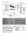
IMPORTANT PRECAUTIONS
2
The decals shown below have been placed on your treadmill, if a decal is missing, or if it is not legible,
please call our toll-free HELPLINE to order a free replacement decal (see the back cover of this manual).
Apply the decal in the location shown.
,_WARHIHG!
• Never allow children
to play on or around
treadmill.
• Storage latch must be
fully engaged before
treadmill is moved or
stored.
G
®
G
(D
I
]
Ji
3
BEFORE YOU BEGIN
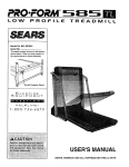
Thank you for selecting the PROFORM e 585 TL treadmill. The 585 TL treadmill blends advanced technology
with innovative design to let you enjoy an excellent
form of cardiovascular exercise in the convenience
and privacy of your home.
For your benefit, read this manual carefully before
using the treadmill. If you have additional questions,
please call our toll-free HELPLINE at 1-800-736-6879,
Monday through Saturday, 7 a.m. until 7 p.m. Central
Time (excluding holidays). To help us assist you,
please note the product model number and serial number before calling. The model number of the treadmill
is 831.297662. The serial number can be found on a
decal attached to the treadmill (see the front cover of
this manual for the location).
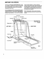
Before reading further, please review the drawing
below and familiarize yourself with the parts that are
labeled.
Book Rack
Console
Accessory Tray
Towel Rack
Incline Control
Water Bottle Holder
(Water Bottle is not
included)
Storage
--
LEFT SIDE
RIGHT SIDE
hts -FRONT
Circuit Breaker
Power Cord
Foot Rails
Walkiig Belt
Front Wheel
Cushioned
Platform
BACK
Roller
Adjustment Bolt
4
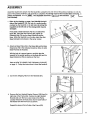
ASSEMBLY
Assembly requires two people. Set the treadmill in a cleared area and remove the packing matedals. Do not dispose of the packing matedals until assembly is completed. Assembly requires the Included allen wrench |,a
phillips screwdriver
(not Included).
_====(Z_),
two adjustable wrenches
_
Refer to the drawing on page 4 and Identify the right
slde of the treadmill. With the help of a second person,
carefully lay the treadmill on its dght side; do not lay the
treadmill on its left side or the storage latch may be
damaged.
.
and scissors
L__
86
76
Firmly slide a Base Extension (76) into one side of the
Base (86). Using the Allen Wrench (89), tighten an
Extension Bolt (13) into the Base Extension and the
Base. While the treadmill is on its side, attach the other
Base Extension (not shown) in the same manner.
e
Attach six Base Pads (43) to the Base (86) and the Base
Extensions (76) in the indicated locations. Note: An extra
Base Pad may be included.
2
With the help of a second person, carefully raise the
treadmill to the updght position so the Base (86) and the
Base Extensions (76) are resting on the floor.
Refer to HOW TO LOWER THE TREADMILL FOR USE
on page 11. Follow the instructions to lower the treadmill.
86
3. Cut the two Shipping Ties from the Handrails (61).
.
3
Shipping
Remove the four Handrail Bracket Screws (128) from the
dght side of the Frame (83). Position the right Handrail
Bracket (42) over the four screw holes in the Frame.
Loosely thread two of the Screws into the back holes of
the Bracket and into the Frame as shown.
Repeat this step on the left side of the Frame (83).
5
Locate the section HOW TO FOLD THE TREADMILL
FOR STORAGE on page 10. Follow the instructions to
fold the treadmill.
Thread two more Handrail Bracket Screws (128) into the
right Handrail Bracket (42) and Frame (83). Firmly
tighten all four Screws in the Bracket. Thread two more
Screws into the left Handrail Bracket and Frame (not
shown). Firmly tighten all four Screws in the Bracket.
6. Refer to HOW TO LOWER THE TREADMILL FOR USE
on page 11. Follow the instructions to lower the treadmill.
6
Align the holes in the Book Rack (101) with the holes in
the Console Base (85). Attach the Book Rack with the
four Console Screws (6) as shown.
.
Remove the backing from the Adhesive Clip (90). Press
the Adhesive Clip onto the Base (86) in the indicated location. Press the Allen Wrench (89) into the Adhesive Clip.
7
86
90-.._._.
.
89
.
6
Make sure that all parts are tightened before you use the treadmill. Note: To protect the floor or carpet,
place a mat under the treadmill. To order a mat, see REPLACEMENT PARTS on the back cover.
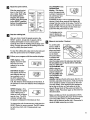
OPERATION AND ADJUSTMENT
THE PERFORMANT
LUBE TM WALKING BELT
Your treadmill features a walking belt coated with
PERFORMANT LUBE TM, a high-performance lubricant.
IMPORTANT: Never apply silicone spray or other
substances to the walking belt or the walking platform. They will deteriorate the walking belt and
cause excessive wear,
electric shock. This product is equipped with a cord
having an equipment-grounding conductor and a
grounding plug. Plug the power cord into a surge
protector, and plug the surge protector Into an appropriate outlet that is properly Installed and
grounded In accordance with all local codes and
ordinances.
This product is for use on a nominal 120-volt circuit,
and has a grounding plug that looks like the plug illustrated in drawing 1 below. A temporary adapter that
looks like the adapter illustrated in drawing 2 may be
used to connect the surge protector to a 2-pole receptacle as shown in drawing 2 if a properly grounded outlet is not available.
HOW TO PLUG IN THE POWER CORD
The temporary adapter should be used only until a
properly grounded outlet (drawing 1) can be installed
by a qualified electrician.
The green-colored rigid ear, lug, or the like extending
from the adapter must be connected to a permanent
ground such as a properly grounded outlet box cover.
Whenever the adapter is used it must be held in place
by a metal screw. Some 2-pole receptacle outlet box
covers are not grounded. Contact a qualified electrician to determine if the outlet box cover Is
Your treadmill, like any other type of sophisticated
electronic equipment, can be seriously damaged by
sudden voltage changes in your home's power.
Voltage surges, spikes, and noise interference can regrounded before using an adapter.
suit from weather conditions or from other appliances
being tumed on or off.
To decrease the possibility of your tread1
/Grounded Outlet Box
mill being damaged,
Treadmill
always use a surge
protector (not In._ Grounding Pin
cluded) with your
Grounding
treadmill.
'__unding
Surge protectors are
sold at most hardware
stores and department
stores. Use only a ULlisted surge protector,
rated at 15 amps, with a
14-gauge cord of five
feet or less in length.
This product must be
grounded. If it should
malfunction or break
Plug
3rounded Outlet
Surge Protector
down, grounding provides a path of least resistance for electric current to reduce the risk of
7
DIAGRAM OF THE CONSOLE
Monitor Displays
_
"/"
i ....
'4,'.,......'',.,_,_"'''''_'"
::..-...::::::.:::::
":.:_':£_:?Z':
..... ;"_"
b._
_:_:::_:
,_';Z:_ SLOW
Cool-.down
_._:;:
TRAiNiNG
ZONES
::::
FAT BURN
_
o[
_4'r
.J.L._ I ml
SPEED
J=" 1"_ ;
CALS.
I FAT CALS.
I PULSE
/11_
q_
THUMB
_
PULSE
SPEED
RESET
l"s-'2
KEY
"ETa'3
RES
SET
fr_,_t_t_4_l,
ttp.
/
Pulse
Sensor
Speed Control /
Incline
Switch
Clip ,,
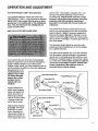
STEP BY STEP CONSOLE OPERATION
Insert the key fully Into the power switch.
Before operating the console, make sure that the power
cord is properly plugged in. (See HOW TO PLUG IN
THE POWER CORD on page 7.) If there is a thin sheet
of clear plastic on the face of the console, remove it.
Inserting the key will
not turn on the displays. The displays will
turn on when the
RESET button is
pressed or when the
walking belt is started.
Next, step onto the foot rails of the treadmill. Find the
clip attached to the key (see the drawing above), and
slide the clip onto the waistband of your clothing.
Follow the steps on pages 8 and 9 to operate the console.
8
B
Reset the speed control.
Slide the speed control
down to the RESET position. Note: Each time
the walking belt is
stopped, the speed
control must be moved
to the RESET position
before the walking belt
can be restarted.
e'lu_rmar_a.'.':::
AeIZIW_::::.
°'::::::::.:
":::::::::'
.......
".':::::P./A#;_::::.'::"
.7".::::::.7:"
:::.\'::.'::."
.\'\\',':.:"
.'*':.;;T
•i-i'i-i-i-i !'i+."/
wa_,._
Cool.dewn
_"i:.:i_
_::i'i",SLOW
_':,+.
TRAININO
;::
":::
zones ::.'i
:"i" speeo
Start the walking belt.
After you have moved the speed control to the
RESET position, slowly slide it upward until the
walking belt begins to move at slow speed.
Carefully step onto the walking belt and begin exercising. Change the speed of the walking belt as desired by sliding the speed control.
To stop the walking belt, step onto the foot rails and
slide the speed control to the RESET position.
Follow your progress with the monitor displays.
TIME display--This
display shows the total
time that you have
walked or run on the
treadmill.
DISTANCE
fat calories you have
burned. (See FAT
BURNING on page 14 for an explanation of fat
calories.) Every seven seconds, the display will
change from one number to the other. The FAT indicator will light when the number of fat calories is
displayed. Note: This display will also show your
pulse when the pulse sensor is used.
pressing the RESET button.
AESET
Measure your pulse, if desired.
To use the pulse
sensor, stand on
the foot rails and
place your thumb
on the pulse sensor as shown.
Pulse
The pulse sensor
is pressure-activated; fully press
down the pulse sensor. Do not press too hard, or
the circulation In your thumb will be restricted,
and your pulse will
not be detected. Next,
slightly raise your
thumb until the heartshaped indicator by
the CALORIES/FAT
Indicator
CALORIES/PULSE
display flashes
steadily. Hold your thumb at this level. After 5 to 10
seconds, your pulse will be shown. Hold your thumb
on the sensor for another 15 seconds for the most
accurate reading. If the displayed pulse appears to
be too high or too low, or if your pulse is not displayed, lift your thumb off the sensor and allow the
display to reset. Pressdown again on the sensor as
described above.
1/2el
display--
total distance
This
display shows
that you
the
have walked or run. if
the KPH indicator be-
J281
cA,s./ _AT
CA,S
/pu,sE
The displays can be
reset, if desired, by
E!
B
display--This display
shows the approximate
numbers of calories and
{ 2._6
!
o,sT,_,_ce
side the SPEED display
is lit, the distance will be displayed in kilometers. If
the indicator is not lit, the distance will be displayed
in miles.
SPEED display--This
display shows the speed
of the walking belt, in
miles per hour or kilometers per hour. The KPH
indicator will light when
the speed is displayed in kilometers per hour.
To change the unit of measurement, hold down the
RESET button for seven seconds. The KPH indicator will show which unit of measurement is selected.
Make sure that your thumb is positioned as shown,
and that you are applying the proper amount of pressure to the pulse sensor. Try the sensor several
times until you become familiar with it. Remember to
stand stillwhile measuring your pulse.
9
Changethe inclineof thetreadmill,if desired.
B
hen you are finished exercising,
walking belt and remove the key.
stop the
To increase
or decrease
the incline, hold down the
top or bottom of the incline
button. Important: Do not
change the Incline of the
treadmill by placing obJects under the treadmill.
Change the Incline only
as described above.
POWER INCUNE
V
Important: Before folding the treadmill, adjust
the incline to the lowest position.
Step onto the foot rails,
stop the walking belt,
and remove the key
from the console. Store
oN opF
I
the key in a secure
place.
Note: Any time that the walking belt is stopped
and no console buttons are pressed for five minutes, the displays will automatically turn off.
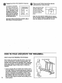
HOW TO FOLD AND MOVE THE TREADMILL
HOW TO FOLD THE TREADMILL FOR STORAGE
Before folding the treadmill, adjust the incline to the lowest
position. If the Incline is not at the lowest position, the
treadmill will be permanently damaged. Next, unplug the
power cord. Caution: You must be able to safely lift 45
pounds (20 kg) In order to raise, lower, or move the
treadmill.
10
1. Hold the treadmill with your hands in the locations shown
at the right. Caution: To avoid pinching your hands, do
not hold the treadmill In the locations indicated by the
arrows. To decrease the possibility of Injury, bend
your legs and keep your back straight. As you raise
the treadmill, make sure to lift with your legs rather
than your back. Raise the treadmill about halfway to the
vertical position.
1
Do not hold here
2. Moveyourrighthandtothepositionshownandholdthe
treadmillfirmly.Raisethetreadmilluntilthestoragelatch
closesover the frame guide. Make sure that the storage
latch closes fully over the frame guide.
To protect the floor or carpet from damage, place a
mat under the treadmill. Keep the treadmill out of direct sunlight. Do not leave the treadmill in the storage
position In temperatures above 85 ° Fahrenheit.
Latch _
Closed
Frame
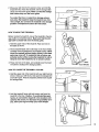
HOW TO MOVE THE TREADMILL
Before moving the treadmill, convert the treadmill to the storage position as described above. Make sure that the storage latch is closed fully over the frame guide.
1. Hold the upper ends of the treadmill. Place one foot on
the base as shown.
2. Tilt the treadmill back until it rolls freely on the front wheels.
Carefully move the treadmill to the desired location. Never
move the treadmill without tipping It back, or the base
pads may come off. To reduce the risk of Injury, use
extreme caution while moving the treadmill. Do not attempt to move the treadmill over an uneven surface.
3. Place one foot on the base, and carefully lower the treadmill until it is resting in the storage position.
HOW TO LOWER THE TREADMILL
Front Wheels
FOR USE
1. Hold the upper end of the treadmill with your right hand as
shown. Using your left thumb, slide open the storage latch
and hold it open. Pivot the treadmill until the frame is past
the storage latch.
Storage
katch_
2. Hold the treadmill firmly with both hands, and lower the
treadmill to the floor. Caution: To avoid pinching your
hands, do not hold the treadmill in the locations indicated by the arrows. To decrease the possibility of injury, bend your legs and keep your back straight.
Opened
Do not hold here
11
TROUBLE-SHOOTING
Most treadmill problems can be solved by following the simple steps below. Find the symptom that applies, and follow the steps listed, if further assistance is needed, call our toll-free HELPLINE at 1-800-736.
6879, Monday through Saturday, 7 a.m. until 7 p.m. Central Time (excluding holidays).
1. SYMPTOM: THE POWER DOES NOT TURN ON
a.
b°
c,
Make sure that the power cord is plugged into a surge protector, and that the surge protector is plugged into
a properly grounded outlet. (See HOW TO PLUG IN THE POWER CORD on page 7.) Use only a UL-listed
surge protector, rated at 15 amps, with a 14-gauge cord of five feet or less in length.
After the power cord has been plugged in, make sure that the key is fully inserted into the console. (See step
1 on page 8.)
Check the circuit breaker located on the treadmill near the
power cord. If the switch protrudes as shown, the circuit
breaker has tripped. To reset the circuit breaker, wait for five
minutes and then press the switch back in.
c
Tripped
Reset
2. SYMPTOM: THE POWER TURNS OFF DURING USE
a. Check the circuit breaker located on the treadmill frame near the power cord (see 1. c. above). If the circuit
breaker has tripped, wait for five minutes and then press the switch back in.
b. Make sure that the power cord is plugged in.
c. Remove the key from the console. Reinsert the key fully into the console. (See step 1 on page 8.)
d. If the treadmill still will not run, please call our toll-free HELPLINE.
3. SYMPTOM: THE WALKING BELT SLOWS WHEN WALKED ON
a. Use only a UL-listed surge protector, rated at 15 amps, with a 14-gauge cord of five feet or less in length.
b. If the walking belt still slows when walked on, please call our toll-free HELPLINE.
4. SYMPTOM: THE WALKING BELT IS OFF-CENTER
WHEN WALKED
a. If the walking belt has shifted to th'_ left, first remove the key and
UNPLUG THE POWER CORD. Using the allen wrench, tum the
left rear roller adjustment bolt clockwise 114 of a turn. Plug in the
power cord, insert the key and run the treadmill for a few minutes. Repeat until the walking belt is centered.
b. If the walking belt has shifted to the right, first remove the key
and UNPLUG THE POWER CORD. Using the allen wrench,
tum the left rear roller adjustment bolt counterclockwise 114 of a
tum. Plug in the power cord, insert the key and run the treadmill
for a few minutes. Repeat until the walking belt is centered.
12
ON
5. SYMPTOM: THE TREADMILL
SITS UNEVENLY ON THE FLOOR
a. Make sure that the six base pads are attached to the treadmill (see assembly step 2 on page 5).
CONDITIONING
GUIDELINES
accessible carbohydrate calories for energy. Only after
the first few minutes does your body begin to use
stored fat calories for energy. If your goal is to bum fat,
adjust the speed and incline of the treadmill until your
heart rate is near one of the lower two numbers in your
training zone. It may also be helpful to set the speed
control on the console to FAT BURN to help you maintain the proper intensity level. (See page 9.)
Aerobic Exercise
The following guidelines will help you to plan your exercise program. Remember-these
are general guidelines only. For more detailed exercise information, obtain a reputable book or consult your physician.
EXERCISE INTENSITY
Whether your goal is to bum fat or to strengthen your
cardiovascular system, the key to achieving the desired
results is to exercise with the proper intensity. The
proper intensity level can be found by using your heart
rate as a guide. The chart below shows recommended
heart rates for fat burning and aerobic exercise.
I
20
30
40
50
60
70
80
AGE
If your goal is to strengthen your cardiovascular system, your exercise must be "aerobic." Aerobic exercise
is activity that requires large amounts of oxygen for
prolonged periods of time. This increases the demand
on the heart to pump blood to the muscles, and on the
lungs to oxygenate the blood. For aerobic exercise,
adjust the speed and incline of the treadmill until your
heart rate is near the higher number in your training
zone. It may also be helpful to set the speed control on
the console to AEROBIC to help you maintain the
proper intensity level. (See page 9.)
High Performance Athletic Conditioning
If your goal is high performance athletic conditioning,
set the speed control on the console to PERFORMANCE to help you maintain the proper intensity level.
(See page 9.) Note: During the first few weeks Of your
exercise program, keep your heart rate near the low
end of your training zone.
To measure your heart rate during exercise, use the
pulse sensor on the console. (See page 9.) If your
heart rate is too high or too low, adjust the speed or incline of the treadmill as needed.
AEROBIC I
MAX. FAT |
FAT BURN |
b.p.rlT.
HEART RATE TRAINING
ZONES
WORKOUT GUIDELINES
Each workout should include the following three pads:
A Warm-up
To find the proper heart rate for you, first find your age
at the top of the chart (ages are rounded off to the
nearest ten years). Next, find the three numbers below
your age. The three numbers are your "training zone."
The lower two numbers are recommended heart rates
for fat burning; the higher number is the recommended
heart rate for aerobic exercise.
Fat Burnfng
14
To bum fat effectively, you must exercise at a relatively
low intensity level for a sustained period of time. During
the first few minutes of exercise, your body uses easily
Start each workout with 5 to 10 minutes of stretching
and light exercise. A proper warm-up increases your
body temperature, heart rate, and circulation in preparation for strenuous exercise.
Tra_lng
Zone Exercise
After warming up, increase the intensity of your exercise until your heart rate is in your training zone for 20
to 60 minutes. (During the first few weeks of your exercise program, do not keep your heart rate in your training zone for longer than 20 minutes.) Breathe regularly
and deeply as you exercise--never hold your breath.
A Cool-down
Exercise Frequency
Finish each workout with 5 to 10 minutes of stretching
to cool down. This will increase the flexibility of your
muscles and will help to prevent post-exercise problems.
To maintain or improve your condition, complete three
workouts each week, with at least one day of rest between workouts. After a few months of regular exercise, you may complete up to five workouts each week
if desired. The key to success is to make exercise a
regular and enjoyable part of your everyday life.
SUGGESTED
STRETCHES
The correct form for several basic stretches is shown in the
drawings below. Move slowly as you stretch--never bounce.
1. Toe Touch Stretch
Stand with your knees bent slightly and slowly bend forward
from your hips. Allow your back and shoulders to relax as you
reach down toward your toes as far as possible. Hold for 15
counts, then relax. Repeat 3 times. Stretches: Hamstrings,
back of knees and back.
2. Hamstring Stretch
Sit with one leg extended. Bring the sole of the opposite foot
toward you and rest it against the inner thigh of your extended
leg. Reach toward your toes as far as possible. Hold for 15
counts, then relax. Repeat 3 times for each leg. Stretches:
Hamstrings, lower back and groin.
3. Calf/AchiUes Stretch
With one leg in front of the other, reach forward and place your
hands against a wall. Keep your back leg straight and your
back foot flat on the floor. Bend your front leg, lean forward and
move your hips toward the wall. Hold for 15 counts, then relax.
Repeat 3 times for each leg. To cause further stretching of the
achilles tendons, bend your back leg as well. Stretches:
Calves, achilles tendons and ankles.
4. Quadriceps
Stretch
With one hand against a wall for balance, reach back and
grasp one foot with your other hand. Bring your heel as close
to your buttocks as possible. Hold for 15 c0unts, then relax.
Repeat 3 times for each leg. Stretches: Quadriceps and hip
muscles.
5. Inner Thigh Stretch
Sit with the soles of your feet together and your knees outward.
Pull your feet toward your groin area as far as possible. Hold
for 15 counts, then relax. Repeat 3 times. Stretches:
Quadriceps and hip muscles.
5
II
I
REMOVE HIS EXPLODED DRAWING
AND PAR LIST FROM HE MANUAL
Save this EXPLODED DRAWING and PART LIST for future reference.
IHIIIII
Note: Specifications are subject to change without notice. For information about
ordering replacement parts, see the back cover of the User's Manual.
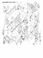
EXPLODEDDRAWINGmModelNO.831.297662
Ro_97A
lol
66*
41
3
62
88
1;
59
6O
95
84
100
,\
15
92
\
130
19
3
28
27
34
39
98
83
15 1
10
16
16
72
77
46
17
14
43./'o
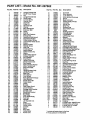
PART LISTmModel
No. 831.297662
Key No. Part No. Qty. Description
1
2
3
4
5
6
7
8
9
10
11
12
13
14
15
16
17
18
19
20
21
22
23
24
25
26
27
28
29
30
31
32
33
34
35
36
37
38
39
40
41
42
43
44
45
46
47
48
' 49
50
51
52
53
54
55
56
57
58
59
60
61
62
63
64
65
66*
67
68
69
70
104725
129345
100427
121421
013322
126996
132549
112669
106334
132449
101149
117806
013484
013300
014073
013162
131826
105444
014127
013456
013576
134300
134302
128272
054023
128986
123470
121576
132456
114270
127597
133072
120630
120354
013547
014117
122812
120867
107503
137365
132440
132422
129740
125677
052012
103833
132394
125819
130251
130993
134347
128479
109382
131753
131738
132466
109265
134303
134305
134307
132426
132565
134323
131161
031108
134324
134326
135866
129875
• 124669
2
1
11
2
10
6
1
1
1
2
2
2
2
20
6
5
4
2
4
4
6
2
8
8
3
1
1
3
2
1
6
6
21
2
1
1
1
1
1
4
1
2
7
5
2
2
5
4
2
1
1
1
1
1
1
1
2
1
1
2
2
1
1
1
1
1
1
1
1
1
Upright Endcap Bolt
Small Power Supply
Nut
Upright Bracket Bolt
Small Screw
Console Screw
Ground Wire
Clevis Pin
Cotter Pin
Hex-head bolt
Washer
Base Wheel Bolt
Extension Bolt
Screw
Washer
Belly Pan Fastener
Endcap Bolt
AdiustmentBolt (short)
AdjustmentWasher
Frame Isolator Screw
Latch Frame Guide Screw
Isolator
Spring Cushion
PlatformScrew
Wire Clip
Tension Spring
Spring Sleeve
RollerTension Nut
Spacer
Incline Motor Spacer
Endcap Fastener
Pan Fastener
Small Screw
Upright Pivot Bolt
Motor Tension Bolt
Star Washer
Motor Tension Washer
Motor Tension Nut
Motor Pivot Bolt
Spring
Upright Endcap (left)
'
Upright Bracket
Base Pad
Hood Anchor
Front Wheel
Base Extension Endcap
Hood Bracket
Plastic Stand-o_
Frame Guide
Choke
Bracket
Rear Roller Guard
Circuit Breaker
Storage Latch Bracket
Storage Latch
Electronics Bracket
Belt Guide
Rear Roller
Front Roller/Pulley
Foot Rail
Handrail
Left Handrail Arm
Hood
Speed Knob
Incline Switch
Console
Motor
Motor Belt
Incline Motor
Power Cord
Ros97A
Key No. Part No. Qty.
71
72
73
74
75
76
77
78
79
80
81
82
83
84
85
86
87
88
89
90
91
92
93
94
95
96*
97
98
99
100
101
102
103
104
105
106
107
108
109
110
111
112
113
114
115
116
117
118
119
120
121
122
123
124
125
126
127
128
129
130
131
#
#
#
#
#
124695
134329
132315
129004
134331
132435
133584
134333
138058
132453
136203
136880
NSP
134335
137465
136073
132455
100498
126040
016028
118153
134342
134343
137409
102073
134328
126747
012149
136377
132424
135025
132441
016057
131605
119038
129232
128113
013162
134338
134337
132031
134388
132456
135004
129639
131562
116926
016029
116892
126130
135992
133333
127819
013375
119425
135665
116927
013540
014063
054023
131090
127860
107771
132371
132370
138428
1
1
1
2
2
2
1
1
1
1
1
1
1
1
1
1
1
1
1
2
1
1
1
1
2
1
1
1
2
1
1
1
5
1
1
2
1
5
1
1
1
2
2
1
1
1
1
2
1
1
2
2
1
1
1
1
1
8
4
3
1
12
1
1
1
1
Description
Grommet
Wire Harness
7 1/2" Wire Tie
Wire Harness Grommet
Shock
Base Extension
Power Supply w/Clips
Controller
Incline Leg
Belly Pan
Endcap Plug
Rear Roller Cover
Frame
Walking Platform
Console Base
Upright/Base
Left Endcap Foot
Magnet
Allen Wrench
Adhesive Clip
Reed Switch Wire
Walking Belt
Frame Cover
Adjustment Bolt (long)
Handlebar Mount Bolt
MotorlPulleylFlywheellFan
Pulley/Flywheel/Fan
Motor Pivot Nut
Latch Spring
Right Handlebar Arm
Book Rack
Right Upright Endcap
8" Wire Tie
Latch Warning Decal
Key/Clip
Storage Warning Decal
Speed Potentiometer
Cover Screw
Incline Cover Shield
Incline Cover
Frame Guide Spacer
Handrail Spacer
Frame Spacer
Choke Plate
Battery Cover
Latch Pad
Releaseable Tie
4" Wire Tie
Incline Bracket
Bracket Plug
Handrail Cover
Incline Cover Clip
Upright Plug
Incline Motor Bolt
Incline Motor Nut
Right Endcap Foot
Wire Tie Clamp
Upright Bracket
Roller Cover Washer
Wire Clip
Reed Switch Clip
Fastener
8" White Wire, Male/Female
6" White Wire, 2 Female
6" Blue Wire, 2 Female
User's Manual
* Includesall parts shown in the box
# These parts are not illustrated
The model number and serial number of your PROFORM ®585 TL
treadmill are listed on a decal attached to the frame. See the front
cover of this manual to find the location of the decal.
Model No. 831.297662
QUESTIONS?
All replacement parts are available for immediate purchase or
special order when you visit your nearest SEARS Service Center.
To request service or to order parts by telephone, call the toll-free
numbers listed at the left.
If you find that:
• you need help assembling or
operating the PROFORM e 585
TL treadmill
• a part Is missing
When requesting help or service, or ordering parts, please be prepared to provide the following information:
• The NAME OF THE PRODUCT (PROFORtvP 585 TL treadmill)
• or you need to schedule repair
service
call our toll-free HELPLINE
• The MODEL NUMBER OF THE PRODUCT (831.297662)
• The PART NUMBER OF THE PART (see the EXPLODED
DRAWING and PART LIST included in this manual)
1-800-736-6879
Monday-Saturday,
7 am-7 pm
Central Time (excluding holidays)
• The DESCRIPTION OF THE PART (see the EXPLODED DRAWING and PART LIST included in this manual).
REPLACEMENT
PARTS
If parts become worn and need
to be replaced, call the following
toll-free number
1-800-FON-PART
(1-800-366-7278)
FULL 90 DAY WARRANTY
For 90 days from the date of purchase, if failure occurs due to defect in material or workmanship in this
SEARS TREADMILL EXERCISER, contact the nearest SEARS Service Center throughout the United
States and SEARS will repair or replace the TREADMILL EXERCISER, free of charge.
This warranty does not apply when the TREADMILL
poses.
EXERCISER is used commercially or for rental pur-
This warranty gives you specific legal rights, and you may also have other rights which vary from state
to state.
SEARS, ROEBUCK AND CO., DEPT. 817WA, HOFFMAN ESTATES, IL 60179
Part No. 138428 G01514AC
R0597A
Printed in USA © 1997 Sears, Roebuck and Co.