1
"
r
]
Gas Water Heater
Owners Manual
NOT FOR USE IN
MOBILE HOMES
MODEL
U
NUMBERS:
153.336331
153.336332
153.336431
153.336432
153.336631
153.336701
153.336801
153.336901
30 Gal.
30 Gal.
40 Gal.
40 Gal.
30 Gal.
30 Gal. High Altitude
40 Gal. High Altitude
30 Gal. High Altitude
o Installation
o Operationo
For Your Safety
Repair Parts
•
us_o
B_T._sW
ATER.EATE_
ANODO.ANT
ISAOOED
_OT.ECAS
FOR YOUR SAFETY
If you smell gas:
1. Do not try to light any appliance.
2. Do not touch any electrical switch; do not
use any phone in your building.
FOR YOUR SAFETY
Do not store or use gasoline or other
flammable
vapors and liquids in the
vicinity of this or any other appliance. _
3. Immedia!ely call your gas supplier from a
neighbor s phone. Follow the gas supplier s
instructions.
4. If you can not reach your gas supplier, call
the fire department.
Flammable vapors may be drawn by air
currents from other areas of the structure to this appliance.
0
WARNING:
Improper
installation,
adjustment, alteration,
service or maintenance
can cause DEATH, SERIOUS BODILY INJURY OR PROPERTY DAMAGE.
Refer to
this manual for assistance or consult your local Sears Service Center or gas Utility
for further information.
WARNING
|
READ THE GENERAL SAFETY SECTION BEGINNING ON INSIDE COVER AND THEN THIS !
ENTIRE MANUAL BEFOREINSTALLING OR OPERATING THIS WATER HEATER.
I
Save this Manual
for Future
Reference.
Z
WARNING
Improper installation, adjustment, alteration, service or maintenance can cause DEATH, SERIOUS BODILY INJURY OR PROPERTY DAMAGE. Refer to this manual for assistanceor consult
your local SearsService Center for further information.
WARNING
At the time of manufacture this water heater was equipped
with a temperature-pressure
relief valve. For protection
against excessive pressures and temperatures in this water
heater, install temperature-pressure protective equipment
required by local codes, but not lessthan a combination temperature-pressure rellef valve certified by nationally recognized tesh_nglaboratory that maintains periodic inspection of
production Of listed equipment or materials, as meeting the
requirements for Relief Valves and Automatic Gas Shutoff
Devices for Hot Water Supply Systems,the latest edition ANSI
Z21.22. This valve must be marked with a maximum set pressure not to exceed the marked hydrostatic working pressure of
the water heater (150 lbs./sq, in.). The relief valve must be
marked with a discharge capacity not less than the water
heater Btu input rate as shown on the model rating plate.
Install the temperature-pressure relief valve directly into the
firing of the water heater. Position the valve downward and
provide tubing so that any discharge will exit only within 6
inches above, or at any distance below the structural floor. Be
certain that no contact is made with any live electrical part.
The discharge opening must not be blocked or reduced in size
under any circumstances. Excessivelength, over 15 feet, or use
of more than two elbows can cause restriction and reduce the
discharge capacity of the valve.
No valve or other obstruction is to be placed between the
relief valve and the tank;. Do not connect tubing directly to
discharge drain unlessa 6' air gap is provided. To prevent bodily iniury, hazard to life, or damage property, the relief valve
must be allowed to discharge water in quantities should circumstancesdemand. If the discharge pipe is not connected to
a drain or other suitable means, the water flow may cause
property damage.
The Discharge Pipe:
-Must not be smaller in size than the outlet pipe size of the
valve, or have any reducing couplings or other restriction.
-Must not be plugged or blocked.
-Must be of maten_al listed for hot water distribution.
-Must be installed so as to allow complete drainage of both the
temperature-pressure relief valve, and the discharge pipe.
-Must terminate at an adequate drain.
-Must not have any valve between the relief valve and tank.
WARNING
A fire can start if combustible materials such as clothing, cleaning materials, or flammable liquids are placed against or next to
the water heater.
WARNING
WATER HEATERSEQUIPPED FOR ONE TYPE GAS ONLY: This
water, heater is equipped for one type gas onl)_.Check the ratmg plate near the gas control valve for the correct gas. DO
NOT USE THIS WATER HEATER WITH ANY GAS OTHER
THAN THE ONE SHOWN ON THE MODEL RATING PLATE.
Failure to use the correct gas can cause problems which can
result in DEATH, SERIOUS BODILY INJURY, OR PROPERTY
DAMAGE. tf you have any questionsor doubts consult your gas
supplier or local utility.
WARNING
INSTALLATION IN RESIDENTIAL AREAS WHERE FLAMMABLE J
LIQUIDS (VAPORS) ARE LIKELYTO BE PRESENTOR STORED
(GARAGES; STORAGE, AND UTILITY AREAS, ETC):
Flammable liquids (such as gasoline, solvents, propane (LP) or
butane, etc.), all of which emit flammable vapors, may be
improperly stored or used in such areas. The gas water heater
ilot hght or main burner can ignite such.vap°rs" The resulting
I_ashbackand fire can cause death or serious burns to anyone
in the area, as well as property damage.
If installation in such areas is your only option, then the installation must be accomplished in a way that the pilot flame and
main burner flame are elevated from the floor at least 18 inches. While this may reduce the changes of flammable vapors
from a floor spill being ignited, gasoline and other flammable
substancesshould never be store{] or used in the same room or
area containing a gas water heater or other open flame or
spark producingappliance.
NOTE: Flammable vapors may be drawn by air currents from
other areas of the structure to the appliance.
WARNING
HOTTER WATER CAN SCALD: Water heaters are intended to
produce hot water. Water heated to a temperature which will
satisfy clothes washing, dish washing, and other sanitizing
needs can scald and permanently injure you upon contact.
Some people are more likely to be permanently injured by hot
water than others. These include the elderly, children, the
infirm, or physlcally/mentaIly handicapped, if anyone using
hot water in your home fits into one of these groups or if there
is a local code or state law requiring a certain temperature
water at the hot water tap, then you must take special precau-_
tions. In addition to usingthe lowest possible temperature set-'
ting that satisfies your hot water needs, some type of tempering device, such as a mixing valve, should be used at the hot
water taps used by these people or at the water heater. Mixing
valves are available at plumbing supply or hardware stores.
Follow manufacturers instructions for i*nstallationof the valves.
Before changing the factory setting on the thermostat, read the
"Temperature Regulation" section ;_nthis manual.
WARNING
BEFORE LIGHTING [PROPANE (L.P.) GAS WATER HEATERS]:
Propane (LP.) gas is heavier than air. Should there be a leak in
the system, the gas will settle near the ground. Basements,
craw/spaces, skirted areas under mobile homes (even when
ventilated), closets and areas below ground level will serve as
pockets for the accumulation of this gas. Before attempting to
light or relight the water heater's pilot or turning on a nearby
electrical light switch, be absolutely sure there is no accumulated gas in the area. Search for odor of gas by sniffing at
ground level in the vicinity of the appliance, tf odor is detected, follow steps indicated at "For Your Safety" on the cover
page of this manual then leave the premises.
WARNING
This water heater must not be installed directly on carpeting.
Carpeting must be protected by a metal or wood panel
beneath the appliance extending beyond the full width and
depth of the appliance by at least 3 inches (76.2mm) in any_
direction,, or if the appliance is installed in an alcove or closet,
the entire floor must be covered by the panel. Failure to heed
this warning may result in a fire hazard.
//
WARNING
_,gas water heater cannot operate properly without the correct amount of air for combustion. Do not install in a confined
area such a closet, unless you provide air as shown in the
"Locating The New Water Heater" section. Never obstruct the
flow of ventilation air. If you have any doubts or questions at
all, call your gas company. Failure to provide the proper
amount of combustion air can result in a fire or explosion and
can cause DEATH, SERIOUS BODILY INJURY, OR PROPERTY
DAMAGE.
WARNING
If this water heater will be used in beauty shops, barber shops,
cleaning establishments, or self-service laundries with dry
cleaning equipment, it is imperative that the water heater or
water heaters be installed so that combustion and ventilation
air be taken from outside these areas. Refer to the"Locafing
The New Water Heater" section of this manual and also the latest edition of the National Fuel Gas Code, ANSI Z223.1, also
referred to as NFPA 54 for specifics provided concerning air
required.
WARNING
VENT DAMPERS - Any vent damper, whether it is operated
thermally or otherwise must be removed if its use _nhibits
proper drafting of the water heater.
Thermally Operated Vent Dampers: Gas-fired water heaters
having thermal efficiency in excessof80% may produce a relatively low flue gas temperature. Such temperatures may not
be high enough to properly open thermally operated vent
dampers. This would cause spillage of flue gases and may
:ause carbon monoxide polsonmg.
Vent dampers must bear evidenc(_of certification as complying
with the latest edition of American National Standard ANSI
Z21.68 (ANSI Z21.66 & 67, respectively, cover electrically and
mechanically actuated vent dampers). Before installation of
any vent damper, consult your local Sears Service Center or
the gas utility for further information.
WARNING
1. The appliance and its individual shutoff valve must be disconnectedfrom the gas supply piping system during any pressure testing of the gas system at test pressures in excess of 'A
pound per square inch (3.SkPa).
2. The appliance must be isolated from the gas supply piping
system by closing its individual manual shutoff valve during
any pressure testing of the gas supply piping system at test
pressuresequal or less than ¼ poundper square inch (3.5kPa).
WARNING
Scoot build-up indicates a problem that requires correction
beforefurther use. Turn "OFF" gasto waterheater and leave
"OFF" until repairs are made, _ecause fai|ure to correct the
causeof the sootingcan resultin a fire or explosioncausing
DEATHSERIOUSBODILY INJURYOR PROPERTYDAMAGE.
WARNING
The water heater with draft hood installed must be properly
vented to a chimney which terminates outdoors. Never operate the water heater unlessit is vented to the outdoors and has
_dequate air supply to avoid risks of improper operation,
_xplosion or asphyxiation.
WARNING
Obstructed or deteriorated vent systemsmay present a serious
health risk or asphyxiation.
WARNING
Chemical vapor corrosion of the flue and vent system may
occur if air for combustion contains certain chemical vapors.
Spra_y..canprop.ellants, cleanin,g.soivents, reffi
g.erator
and. air
conditioner refrigerants, swimming pool chemicals, calcium
and sodium chloride, waxes, bleach, and process chemicals
are typical compounds which are potentially corrosive.
WARNING
Minimum clearancesbetween the water heater and combustible
construction are 1" at the sidesand rear, 4" at the front, and 6"
from the vent pipe. Clearance from the top of the jacket is 12".
Refer to the label on the water heater located adjacent to the
gascontrol valve for all clearances.
WARNING
HYDROGEN GAS: Hydrogen gas can be produced in a hot
water system that has not been used for a long period of time
enerally two weeks or more). Hydrogen gas is extremely
mmabte and explosive. To prevent the possibility of injury
under these conditions, we recommend the hot water faucet
be opened for several minutes at the kitchen sink before any
electrical appliances which are connected to the :hot water
Systemare used (such as a dishwasher or washing machine). If
hydrogen gas is present, there will probably be an unusual
sound similar to air escaping through the pipeas the hot water
faucet is opened. There must be no smoking or open flame
near the faucet at the time it iSopen.
WARNING
INSULATING JACKETS: When installing an external water
heater insulation jacket on an gaswater heater:
a. DO NOT cover the temperature-pressurerelief valve.
b. DO NOT put insulation over any part of the top of the gas
water heater.
c. DO NOT put insulation over the gas control valve or gas control valve/burner cover, or any access areas to the burner.
d. DO NOT let insulation around the gas water heater to get
within 8 inchesof the floor (air must get to the burner).
e. DO NOT cover or remove operating instructions, and safety
related warning labels and materials affixed to the water
heater.
Failure to heed this will result in the possibility of a fire or
explosion.
CAUTION
WATER HEATERSEVENTUALLY LEAK:Installation of the water
heater must be accomplished in such a manner that if the tank
or any connections should leak, the flow of water will not
causedamage to the structure. When such locations cannot be
avoided, a suitable drain pan must be installed under the
water heater. Drain pans are available at your local Sears
Store. Such a drain pan must be not greater than 11½inches
deep, have a minimum length and width of at least 2 inches
greater than the water heater dimensionsand must Me piped to
an adequate drain. Under no circumstances is the manufacturer or Sears to be held liable for any water damage in connection with this water heater.
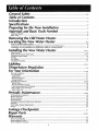
General Safety .....................................................................................
_,_
Table of Contents ................................................................................
:...........
...... 4
Introduction ..............................................................................................
..........................
5
Specifications .....................................................
.............................................................
:..s
i
Preparing for the New Installation ................
:..............................
:..................
Materials and Basic Tools Needed. .........................................................
6
Materials Needed ..................................................................................................................................................
Basic Tools ............................................................................................................................................................
6
6
Removing the OM Water Heater. ............................................
i.........
".................
_
:::::::::::::::::::::::::::::::::::::::::::::::::::::::::::::::::::
Combustion
Combustion
Air and Ventilation
Air and Ventilation
for Appliances
for Appliances
Located in Unconfined
Spaces .....................................................
Located in Confined Spaces .........................................................
9
9
installing the New Water Heater .....................................................
io._
Water Piping ........................................................................................................................................................
10
Temperature-Pressure
Relief Valve ..................................................................................
................................
10,11
Filling the Water Heater .......................................................................................................................................
11
Venting ..................................................................................
.. .............................................
,..............................
11
Gas Piping ....................................................
_.............................
:........................................................................
12
Installation Checklist ...........................................................................................................................................
13
Li_htin_ ............................................................................
:...........................................................
14,15
Temperature Regulation .....................................................................
i............
_
For Your Information .................................................
_..................................................
1_,18
Start Up Conditions .............................................................................................................................................
17
Condensation .........................................................................................
:..........................................................
17
Smoke/Odor .......................................................................................................................................................
17
Thermal Expansion ..........................
:.................................................................................................................
17
Strange Soun_g. .................................................................................................................................................
17
Operational Conditions ..................................................................................................................................
17,18
Smelly Water ........................................................................................................................
........................ 17,18
'_Air"In Hot Water Faucets .... :............................................................................................................................
t8
High Temperature Shut Off System ...........................................................................
.........................................
18
Not Enough or No Hot Water ............................................................................................................................
18
Water Is Too Hot ............................................................................
.....................................................................
18
Periodic Maintenance ..............................................................................
_,_o
Venting System Inspection ...................................................................................................................................
Burner Inspection ................................................................................................................................................
Burner Cleaning ..................................................................................................................................................
Housekeeping .....................................................................................................................................................
Temperature-Pressure
Relief Valve Operation ......................................................................................................
Draining .......................................................................................
_.......................................................................
Drain Valve Washer Replacement .......................................................................................................................
Service .................. :...........................................................................................
. .................................................
19
19
19
19
20
20
20
20
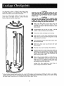
Leakage Checkpoints
" ...............................................................................
_
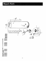
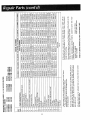
Repair Parts ..........................................................................................
:.......................
_.................
22-23
warranty ...................................
.................................................................................
24
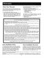
About Your W_rran_ .....................................
_..............................................
................. ......................................
24
Sears Installation Policy .........................................................................................
_..............................................
2"4
Sears Installation Warranty ...............................................
:..........................................................................
........ 24
4
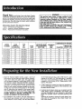
thank Youforpurchasing
a Sears water heater. Properly
installed and maintained, it should give you years of trouble free
service. If you shoufd decide that you want the new water heater
professionally insta]led, contact the local Sears Service Center or
any Sears store. They will arrange for prompt, quality installation
by Sears authorized contractors.
Abbreviations Found in This Instruction Manual
A.G.A. - American Gas Association
A.N.S.I. - American National Standards Institute
N.F.P.A. - National Fire Prevention Association
MODEL
NUMBER
153.336331
I.
TANK
j
CAPACITY t
IN GALLONSl
30
WARNING
................
This gas-fired water heater is design certified by the
American
Gas Association Laboratories under
American National Standards for Gas Water Heaters.
The installation must conform with this manual, Local
Codes and with the latest edition of the National Fuel
Gas Code, ANSI Z223.1.
This publication is available from your local government or public l_rary, gas company, or by writing
NFPA, Batterymarch Park, Quincy, MA 02269.
RECOVERYRATE
GALS. PERHOUR
@90°F RISE
DIMENSIONS IN INCHES
........
HEIGHT TO
DIAMETER JACKETTOP
TYPE
OF
GAS
B.T.U.
RATE
NATURAL
33,500
34.3
3"
16"
56"
MINIMUM
VENT
PIPE
153.336332
30
NATURAL
33,500
34.3
3"
16"
56"
153.336431
40
36.3
36.3
3"
18"
40
NATURAL
NATURAL
35,500
153.336432
153.336631
3"
1 8"
561/_
'
56½"
30
• PROPANE
34.3
3"
16"
56"
153.336701
30
34.3
3"
16"
56"
40
NATURAL
NATURAL
33,500
153.336801
153.336901
30
PROPANE
35,50O
33,500
36.3
3"
3"
18"
16"
561#'
56'
35,500
33,500
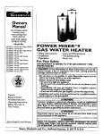
Read the "General Safety" section, pages 2 and 3 of
this manual first and then the entire manual carefully.
If you don't follow the safety rules, the water heater
will not operate properly. It could cause DEATH, SERIOUS BODILY INJURY AND/OR PROPERTY DAMAGE.
This manual contains instructions for the installation,
operation,
and maintenance
of the gas-fired
water
heater. It also contains warnings through out the manua] that you must read and be aware of. All warnings
and all instructions are essential to tee proper operation of the water heater and your safety. Since we cannot put everything
on the first few pages, READ THE
ENTIRE
MANUAL
BEFORE
ATTEMPTING
TO
INSTALL OR OPERATE THE WATER HEATER.
2. The installation must conform with the instructions in
this manual; gas company rules; and Local COdes, or
in the absence oI Local Codes, with the latest edition
34.3
of the National Fuel Gas code, ANSl Z223.1, also
referred to as NFPA 54. This publication is available
from your local government or public library or gas
company or by writing NFPA, Batterymarch Park,
Quincy, MA 02269.
3. if after reading this manual you have any questions or
do not understand any portion of the instructions, call
the SearsService Center.
4. Carefully plan the place where you are going to put the
water heater. Correct combustion, vent action, and
vent pipe installation are very important in preventing
death from possible carbon monoxide poisoning and
fires.
Examine the location to ensure the water heater complies with the "Locating the New Water Heater" section in this manual.
............I
I1'
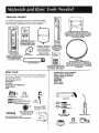
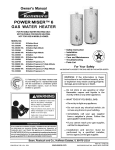
Materials Needed
To simplify the installation Sears has available the instailation parts shown below. You may or may not need all of
these materials, depending on your type of installation.
Compression
¢ou_llr_s
WATER HEATER STAND 24"x24"x18"
FOR USE WITH WATER HEATERS INSTALLED
IN RESIDENTIAL GARAGES HAVING
A DIAMETER 24" OR LESS AND A RATED CAPACITY
75 GALLONS OR LESS
COMPRESSION
COUPLI NGS
FOR CONNECTING
TO
- COPPER PLUMBING
WITH_
/
" OUT+SWEAT
"
'
B
WATER HEATER
.INSTALLATION
KIT WITH
FLEXIBLE CONNECTORS
FOR
3/4" GALVANIZED
OR
1/2"COPPER
PLUMBI NG
SOLDERING
_
U
EXPANSIONTANKS._
__F_R
_ : THERMAL EXPANSION
CONDITIONS
AVAILABLE IN 2 GALLON AND
5 GALLON CAPACITY
THROUGH
LOCAL
SEARS SERVICE CENTERS,
VENT ELBOW
FLE _IBLE WATER
HEATER GAS CONNECTOR WITH
FITTINGS
Wate_ He_tef
Heat Traps
VENT EXTENSION
WATER HEATER HEAT TRAPS
HELP REDUCE HEAT LOSS DUE
TO THERMAL SYPHONING
Basic Tools
You may or may not need all of these tools, depending on
your type of installation. These tools can be purchased at
your local Sears store.
GARDEN
HOSE
6 FOOT
ADDITIONAL
TOOLS NEEDED
WHEN SWEAT SOLDERING
Tubin_ Cutters or Hacksaw
Propa_neTorch
Soft Solder
Solder Flux
Emery_Cloth
Wire Brushes
_
'
i::
L
DHII :
+
Pipe Wrenches (2) 14"
Screwdriver
Tin Snips
_
6Foot 1-ape of Folding Rule
Garden Hose ....
DRAIN PANS
AVAILABLE IN 20" DIAMETER FOR
WATER HEATERS HAVING A DIAMETER 18"
OR LESS AND AVAILABLE IN 28" DIAMETER
FOR WATER HEATERS HAVING
A DIAMETER
26" OR LESS
TAPE
HACKSAW
SLOT-HEAD
SCREWDRIVER
PIPE
WRENCH
PHILLIPS
SCREWDRIVER
3/4" WIRE BRUSH
1/2" WIRE
ROLL OF TEFLON TAPE
(USE ONLY ON WATER
CONNECTIONS)
PIPE DOPE (SQUEEZE TUBE)
(USE FOR WATER AND GAS CONNECTIONS)
BRUSH
ROLL OF LEAD FREE
SOFT SOLDER
SOLDER FLUX
ROLL OF EMERY
CLOTH
PROPANE
TUBING
TORCH
CU]-[ER
Q
Turn "OFF" the gas supply to the water heater.
WARNING
If the main gas line shutoff valve sewing all gas appliances is used, also shut
"OFP' the gas at each appliance. Leave
all gas appliances shut "OFF" until the
water heater installation
is completed.
®
®
Q
Turn
water
valve
tions
off to
Disconnect the vent pipe from the draft hood
where they connect to the water heater. In most
installations the vent pipe can be lifted off after
any screw or other attached devices are removed.
Dispose of the draft hood. The new water heater
has the draft hood which must be used for proper
operation.
©
a,
If you have copper piping to the
water heater, the two copper water
pipes can be cut with a hacksaw
approximately four inches away
from where they connect to the
water heater. This will avoid cutting
off the pipes too short. Additional
cuts can be made later if necessary.
Disconnect the temperature-pressure relief valve drain line. When
the water heater is drained, disconnect the hose from the drain valve.
Close the drain valve.The water
heater is now cornplete[y disconnected and ready to be removed.
"OFF" the water supply
to the
heater at the water shut off
or water meter. Some installarequire that the water be turned
the entire house.
QCheck
again to
supply is "OFF"
Then disconnect
nection from the
If you have galvanized pipe to the
water heater, loosen the two galvanized pipes with a pipe wrench at
the Union in each line. Also disconnect the piping remaining to
the water heater. These pieces
should be saved since they may be
needed when reconnecting the
new water heater. Disconnect the
temperature-pressure relief valve
drain line. When the water heater
is drained, disconnect the hose
from the drain valve. Close the
drain valve.The water heater is
now completely disconnectedand
ready to be removed.
make sure the gas
to the water heater.
the gas supply congas control valve.
Attach a hose to the water heater
drain valve and put the other end in
a floor drain or outdoors. Open the
water heater drain valve. Open a
nearby hot water faucet which wilt
relieve pressure in the water heater
and speed draining.
WARNING
CAUTION
Mineral buildup or sediment may have accumulated
in the old water heater. This causes the water heater
to be much heavier than normal and this residue, if
spilled out, could cause staining.
The water passing out of the drain valve may be
extremely hot. To avoid beingscalded,
make sure
all connections are tight and t_at the water flow is
directed away from any person. _
7
WARNING
Facts to Consider About the
Location
Propellants of aerosol sprays and volatile compounds,
(cleaners, chlorine based chemicals, refrigerants, etc.)
in addition to being highly flammable in many cases,
will also change to corrosive hydrochloric acid when
exposed to tee combustion
products of the water
heater. The results can be hazardous, and also cause
product failure.
You should carefully choose an indoor location for the
new water heater, because the placement is a very important consideration for the safety of the occupants in the
building and for the most economical use of the appliance. This water heater is not for use in mobile homes or
outdoor installation.
2. The Iocation selection must provide adequate clearances for servicing and proper operation of the water
heater.
Whether replacing an old water heater or putting the
water heater in a new location, the following critical
points must be observed.
WARNING
t. The location selected should be indoors as close as
practical to the gas vent or chimney to which the
water heater vent iS going to be connected, and as
centralized with the water piping system as possible.
The water heater, as all water heaters, Will eventually
leak. Do not install without adequate drainage provisions Where waterflow will cause damage.
This water heater must not be installed directly on carpeting. Carpeting
must be protected by a metal or
woodpanel
beneath the appliance extending beyond
the fullwidth
and depth of-tTae appliance by at least 3
inches (76.2mm) in any direction, or if the appliance is
installed in an alcove or closet, the entire floor must be
covered by the panel. Failure to heed this warning may
result in a fire hazard.
CAUTION
The installation of the water beater must be accomplished in such a manner that if the tank or any connections should leak, the flow of water will not cause damage to the area adjoining the water heater, or to the
lower floors of the structure. When such locations cannot be avoided, a suitable drain pan should be installed
under the water heater. Drain pans are available at your
local Sears store. Such a ]_an s]lould be nogreater
than
1½ inches deep, have a minimum length and-width of at
least two inches greater than the water heater dimensions and must be piped to an adequate drain. The pan
must not restrict combustion air flow. Under no circumstances is the manufacturer or Sears to be held liable for
any water damageJ_connection
with this water heater.
WARNING
Minimum clearances between the water heater and
combustible construction are 1" at the sides and rear, 4" at
the front, and 6" from the vent pipe. Clearance from the
top of the _acket is either 12" or 18". Refer to the label on
the water heater located adjacent to the gas control valve
for all clearances.
m
]2" MAX
_
ivIIN.
VENTU.A_ON
AIR
OPENINGS
NNI
6" N]N_L.
WARNING
4"
I'"MIN,
TOP VIEW
OF (_L,OSET
WITHOUT DOOR
m
t2.._"M/_X
i" M|N.
TOP VIEW
OF CLOSET
WITH DOOR
VIEW
OF DOOR
INSTALLATION
IN
RESIDENTIAL
AREAS WHERE
FLAMMABLE LIQUIDS (VAPORS) ARE LIKELY TO BE PRESENT OR STORED (GARAGES, STORAGE AND UTILITY
AREAS, ETC)" Flammable liquids (such as gasoline, solvents,
propane (LP) or butane, etc.) or other substances (such as
adhesives, etc.), all of which emit flammable vapors, may be
improperly stored or used in such areas. The gas water
heater, pgot li ht or main burner can i nite such va.pors.The
resulting flashback and fire can cause _eath or senous burns
to anyone in the area, as well as property damage.
tf installatlon in such areas is your only option, then the
installation must be accomplished in a way that the pilot
flame and maln burner flame are elevated from the floor at
least 18 inches. While this may reduce the changes of
flammable vapors from a floor spill being ignited, gasoline
and other flammable substances should never be stored or
used in the same room or area containing a gas water
heater or other open flame or spark producing appliance.
Also, the water heater must be located and/or protected so
it is not subject to physical damage by a moving vehicle.
NOTE: Flammable vapors maybe drawn by air currents
from other areas of the structure to the appliance.
I Figure 1 j
AIR DUCT
WARNING
A gas water heater cannot operate properly without the
correct amount of air for combustion. Do not install in a
confined area such as a closet, unless you provide air as
shown in Figures 1-5. Never obstruct the flow of ventilation air. If you have any doubts or questions at all, call
your gas company or Sears Service Center. Failure to
provide the proper amount of combustion air can result
in a fire or exp|osion and can cause DEATH, SERIOUS
BODILY INJURY, OR PROPERTY DAMAGE.
if this water heater will be used in beauty shops, barber
shops, cleaning establishments or self-service laundries
with dry cleaning equipment, it is imperative that the
water heater or water heaters be installed so that combustion and ventilation air be taken from outside these
areas. Refer to the "Locating the New Water Heater section" of this manual and also the latest edition of the
National Fuel Gas Code, ANSI Z223.1, also referred to as
NFPA 54 for specifics provided concerning air required.
8
Combustion Air and Ventilation
for Appliances Located in
Unconfined Spaces
-UnconfinedSpaceis a space whose volume is not lessthan 50
cubic feet per 1,000 Btu per hour of the aggregateinput rating
of all appliances installed in that space. Roomscommunicating
directly with the space in which the appliances are installed,
through openings not furnished with doors, are considered a
part of the unconfined space
in unconfined spacesin buildings, infiltration may be adequate
to provide air for combustion, ventilation and dilution of flue
gases.However, in buildings of tight construction (for example,
weather stripping, heavily insulated, caulked, vapor barrier,
etc.), additional air may need to be provided usingthe methods
described in Combustion Air and Ventilation for Appliances
Located in Confined Spaces.
1. When directly communicating
with the Outdoors, each
opening shall have a minimum free area of I square inch
per 4,000 Btu per hour of total input rating of all
equipment in the enclosure. (See Figure 3.)
2. When communicating
with the outdoors through vertical
ducts, each opening shall have a minimum free area of 1
square inch per 4,000 Btu per hour of total input rating of
all equipment in the enclosure. (See Figure 4.)
Q'_"
each
Combustion Air and Ventilation
'for Applia_ncesLocated in
Confined Spaces
Confined Spaceis a space whose volume is lessthan 50 cubic
feet per 1,000 Btu per hour of the aggregateinput rating of all
appliances installed in that space.
a. ALLAIR FROM INSIDE BUILDINGS:
(SeePage8 Figure 1, and Figure.2 below)
The confined space shall be provided with two permanent
openings communicating directly with an additional room(s)
of sufficient volume so that the combined volume of all
spaces meetsthe criteria for an unconfined space. The total
input of all gas utilization equipment installed in the
combined space shall be considered in making this
determination. Eachopening shall have a minimum free area
of one square inch per 1,000 Btu per hour of the total input
rating of all gas utilization equipment in the confined space,
but not less than 100 square inches. One opening shall
commence within t2 inches of the top and one commencing
within 12 inches of the bottom of the enclosure.
OR GAS
CHIMNEY
VENT
iJ_,_ VE_T,U_ION
LOU'._RS
end
ol atilt)
U'rLET
!l = Yi 4t4fl WATER
H_a_
II ]1=,_
_cE
11
_-4 I ILlllA_R
IN_T
Jti
IEND_
1" ABOVE FLOOR)
Figure 4 1
3. When communicating
with the outdoors through
horizontal ducts, each opening shah have a minimum free
area of 1 square inch per 2,000 Btu per hour of total input
rating of all equipment in the enclosure. (See Figure 5.)
I_EY
OR GAS VENT
INLET
FUR._.F. I WAT_II
(LOUVERS,_._F.F_S. Er¢._
b. ALLAIR FROM OUTDOORS: (see Figures 3-5)
The confined space shall be provided with two permanent openings, one commencing within 12 inches of the
top and one commencing within 12 inches from the bottom of the enclosure. The openings shall communicate
directly, or by ducts, with the outdoors or spaces (crawl or
attic) that freely communicate with the outdoors.
If
!_==_
']
_
Jlil n kg_l---tt
WAT'F_ HFJ_-TER
_E
1
Figure 3 I
VE@'nLA]ION
LOLtV_S
4. When ducts are used, they shall be of the same cross-sectional area as the free area of the openings to which they
connect. The minimum short side dimension of rectangular
air ducts shall not be less than 3 inches. (See Figure 5.)
5. Louvers and Grilles: In calculating free area, consideration
shall be given to the blocking effect of Iou_,ers, grilles or
screens protecting openings. Screens used shall not be
smaller than ¼ inch mesh. ff the free area through a design
of louver or grille is known, it should be used in calculating the size opening required to provide the free area specified. If the design and free area is not known, it may be
assumed that wood louvers will be 20-25 percent free area
and metal louvers and grilles will have 60-75 percent free
area. Louvers and grilles shah be fixed in the open position
or interlocked with the equipment so that they are opened
automatically during equipment operation.
6. Special Conditions Created by Mechanical Exhausting or
Fireplaces: Operation of exhaust fans, ventilation systems,
clothes dryers or fireplaces may create conditions requiring
special attention to avoid unsatisfactory operation of
installed gas utilization equipment.
.
Water Piping
WARNING
HOTTER WATER CAN SCALD: Water heaters are intended to
produce hot water. Water heated to a temperature which
will satisfy clothes washing, dish washing, and other sanitizing needs can scald and permanently injure you upon contact. Some people are more likely to be permanently injured
bY hot water than others. These include tile elderly, children,
the infirm, or physically/mentally handicapped. If anyone
using hot water in your home fits ,nto one of thesegroups or
if there is a local code or state law requiring a certain temperature water at the hot water tap, then you must take special precautions, in addition to usingthe lowest possibletemperature setting that satisfies your hot water needs, some
type of tempeffng device, such asa mixing valve, should be
used at the hot water taps used by these people or at the
water heater. Mixing valves are available at plumbing supply
or hardware stores. Follow manufacturers instructions for
installation of the valves. Before changing the factory setting
on the thermostat, read the "Temperature Regulation" section
in this manual.
NOTE: This water heater is super insulated to minimize heat loss from the tank. Further reduction in
heat loss can be accomplished by insulating the hot
water lines from the water heater.
Temperature-Pressure Relief Valve
WARNING
This water heater shall not be connected to any heating
systems or component(s) used with a non-potable water
heating appliance.
NOTE: To protect against untimely corrosion of hot and
cold water fittings, ]t is strongly recommended that dielectric unions or couplings be installed on this water
heater when connected to copper pipe.
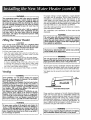
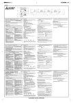
The illustration Shows the attachment of the water piping
to the water heater. The water heater is equipped with ¾
inch water connections.
NOTE: If using copper tubing, solder tubing to an
adapter before attaching the adaptor to the cord water
inlet connection.
Do not solder the cold water supply
llne directly to the cold water inlet. It will harm the dip
tube and damage -the tank.
1. Look at the top cover of the water heater. The water
outlet is marked hot. Put two or three turns of teflon
tape around the threaded end of the threaded-to-sweat
coupling and around both ends of the ¼" threaded nipple. Using flexible connectors, connect the hot water
pipe to the hot water outlet on the water heater.
INSTALLATION COMPLETED USING
SEARS INSTALLATION KIT
SHUTOFF
HOT OUTLET
TO HOUSE
FLEXIBLE
WATER
CONNECTORS
-_-'--'ac_gl)_JJ,_j<.
_THREADEDtO
_.
SwEatcOUPLznG =
_.1.
!$I
/
$ :_
_
COLDwATERINLETLINE
THREADEDTO
.
sweat cOuPLlnC
-_
3/4" THREADED
VALVE
+._
_
temPe_ture_
Look at the top cover of the water heater. The cold
water inlet is marked cold. Put two or three turns
teflon tape around the threaded end of the threade6
to-sweat coupling and around both ends of the ¾"
threaded nipple, Using flexible connectors, connect
the cold water pipe to the cold water inlet of the water
heater.
PRESSURE RELIEF
At the time of manufacture this water heater was equipped
with a temperature-pressure relief valve. For protection
against excessive pressures and temperatures in this water
heater, install temperature-pressure protective equipment
required by local codes, but not less than a combination
temperature-pressure relief valve certified by nationally
recognized testing laboratory that maintains periodic
inspection of production of listed equipment or materials, as
meeting the requirements for Relief Valves and Automatic
Gas Shutoff Devices for Hot Water Supply Systems, the
latest edition ANSI Z21.22. This valve must be marked with
a maximum set pressure not to exceed the marked
hydrostatic working pressure of the water heater (150
Ibs./sq. in.). The reh'ef valve must be marked with
discharge capacity not less than the water heater Btu inpu.
rate as shown on the model rating plate.
Install the temperature-pressure relief valve directly into the
fitting of the water heater. Position the valve downward and
prov,_e tubing so that any discharge will exit only within 6
inches above, or at any distance below the structural floor.
Be certain that no contact is made with any live electrical
part. The discharge opening must not be blocked or reduced
,'n size under any circumstances. Excessive length, over 15
feet, or use of more than two elbows can cause restriction
and reduce the discharge capacity of the valve.
No valve or other obstruction is to be placed between the
relief valve and the tank. Do not connect tubing directly to
discharge drain unless a 6" air gap is provided. To prevent
bodily injury, hazard to life, or damage property, the relief
valve must be allowed to discharge water in quantities
should circumstances demand. If the discharge pipe is not
connected to a drain or other suitable means, the water
flow may. cause property damage.
The Discharge Pipe:
-Must not be smaller in size than the outlet pipe Size of the
valve, or have any reducing couplings or other restriction.
-Must not be plugged or blocked.
-Must be of mater,'ai listed for hot water distribution.
-Must be installed so as to allow complete drainage of both
the temperature-pressure relief valve, and the discharge
pipe.
-Must terminate at an adequate drain.
-Must not have any valve between the relief valve and tank.
If the water heater is installed using a check valve in tff
water line or a water meter with a check valve, contac
the local uti]ity or local Sears Service Center on how to
control this situation.
t0
For proper venting in certain installations, a larger diameter
vent pipe may be necessary. Due to great variances in
installations,
unforeseeable
by the manufacturer
of the
water heater, you must consult your gas company to aid
you in determining the properWenting for your "water heater
from the vent tables in the latest edition of the National Fuel
Gas Code ANSI Z223.1, also referred to as NFPA 54:
WARNING
The temperature-pressure
relief valve must be manually
operated at least once a year. Caution should be taken to
ensure that (1) no one is in front of or around the outlet of
the temperature-pressure relief valve discharge line, and (2)
the water manually discharged will not cause any bodily
injury or property damage because the water may be
extremely hot.
if after manually operating the valve, it fails to completely
reset and continues to release water, immediately close the
cold water inlet to the water heater, follow the draining
instructions, and replace the temperature-pressure relief
valve with a new one.
Check the venting system for signs of obstruction or deterioration and replace if needed.
The combustion
and ventilation
air flow must not be
obstructed.
WARNING
The water beater with draft hood installed must be Connected to a chimney which terminates to the outdoors. Never
operate the water heater unless it is vented to the outdoors
and has adequate air supply to avoid risksof improper operation, explosion or asphyxiation.
Filling the Water Heater
CAUTION
Never use this water beater unless it
with water. To prevent damage to the
be fiUed with water. Water must flow
faucet before turning "ON" gas to the
is completely filled
tank, the tank must
from the hot water
water heater.
WARNING
To fill the water heater with water:
1. Close the water heater drain valve by turning the handle to the right (clockwise).
The drain valve is on the
lower front of the water heater.
2. Open the cold water supply valve to the water heater.
NOTE: The cold water supply valve must be left open
wben the water heater is _n use.
• l-o insure complete filling of the tank, allow air to exit
by opening the nearest hot water faucet. Allow water
to run until a constant flow is obtained. This will let air
out of the water heater and the piping.
4. Check all new water piping for leaks. Repair as needed.
Obstructed
deteriorated
vent systems may present
serious bealthor risk
or asphyxiation.
WARNING
,
The vent p!pefrom the water_heater.must he no lessthan the I
diameter of the draft hood outlet on the water heater, and must i
slope upward to the chimney at least ¼ inch per linear foot.
I
All vent gases must be completely vented to the outdoors
of the structure (dwelling). Install only the draft hood provided with the new water heater and no other draft hood.
Vent pipes must be secured at each joint with sheet metal
screws.
Venting
WARNING
VENT DAMPERS - Any vent damper, whether it is operated
thermaffy or otherwise must be removed if its use inhibits
proper drafting of the water heater.
Thermally Operated Vent Dampers: Gas-fired water heaters
having thermal efficiency in excess of 80% may produce a
relatively low flue gas temperature. Such temperatures may
not be high enough to properly open thermally operated
vent dampers. This would cause spillage of flue gases and
may cause carbon monoxide poisoning.
Vent dampers must bear evidence ofcertlfication as complying with the latest edition of the American Natlonal
Standard ANSI Z21.68 (ANSI Z21.66 & 67, respectively,
cover electrically and mechanically actuated vent dampers).
Before installatmn of any vent damper, consult the local
Sears Service Center or gas utility for further information.
__--_
r
CHIMTONEY
tl
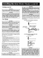
VENT PIPEINSTALLATION
There must be a minimum
of 6 inch clearance between
single wall vent pipe and any combustible
material. Fill
and seal any clearance between single wall vent pipe and
combustible
material with mortar mix, cement, or other
noncombustible
substance. For other than single wall, follow vent pipe manufacturer's
clearance specifications.
To
insure a"tight fit of the vent pipe in a brick chimney, seal
around the vent pipe with mortar mix cement.
WARNING
i To insure proper venting of this gas-fired water heater, the
correct vent p,"pediameter must be utilized. Any additions or
Jeletions of otl_er gas appliances on a common _ventwith this
water heater may adver-selyaffect the operation of the water
heater. Consult the local Sears Service Center or gas utility if
any such changesare planned.
I
WARNING
J Failure to have required clearances between vent piping
and combustible material will result in a fire hazard.
11
I
J
WARNING
Venting (cont'd)
The applianceand itsindividualshutoffvalvemustbe discon,
nectedfrom the gassupplypipingsystemduringanypressure
testingof that systemat test pressures
in excessof ½ pound
per squareinch(3.SkPa).
'rheappliancemustbe isolatedfrom the gassupplypiping sys.
tern by closingits individualmanual shutoffvalveduring any
pressuretestingof the gassupplypipingsystemat test pressuresequalto or lessthan ½poundpersquareinch(3.SkPa).
WARNING
f dangerousflue
Besurevent pipeis
properlyconnected
to preventescapeof
gases
whichcouldcausedeadlyasphyxia|ion;
WARNING
Chemicalvapor corrosionof the flue and vent systemmay
occur if air for combustioncontainscertainchemicalvapors.
Spra ..canpropellants,
.
cleanin
.g. solvents,refrig.erator and.air
con_tmner refrigerants,swwmmmg
pool chemicals,caicmm
and sodiumchloride,waxes,bleachand processchemicals
aretypicalcompoundswhicharepotentiallycorrosive.
Use pipe joint compound or teflon tape marked as being
resistantto the action ofWARNING
petroleum [Propane(L.P.)]gases. 1
Connecting the gas piping to the gas control valve of the
water heater can be accomplished by either of the two
methods shown.
Caspiping
GAS PIPING WITH FLEXIBLECONNECTOR
WARNING
.......
GAS SUPPLY PIPING
Make sure the gassupplied is the same type listed on the
modelrating plate.The inletgaspressuremustnotexceed14
incheswatercolumn[½pound per squareinch(3.5kPa)].
_
MANUAL SHUTOFF VALVE
WARNING
if thegas controlValveis subjectedto pressures
exceeding½
poundper squareinch (3.5kPa),the damageto the gas control valvecould resultin a fire or explosionfrom leakinggas.
...........
WARNING
FLEXIgLE GAS CONNECTOR
LABELED AS COMPLYING
WITH ANSI STANDARDS
GROUND JOINT
UNION (OPTIONAL)
LOOP
......
GAS
CONTROL
VALVE
if the maingasline shutoffservingall gasappliancesis used,
alsoturn "OFF"the gasat eachappliance.Leaveall gasappliancesshutoff until t-hewater heaterinstallationiscomplete.
6"
A gas line of sufficient size must be run to the water
heater. Consult the latest edition of National Fuel Gas
Code ANSI Z223.1, also referred to as NFPA54 and the
gas company concerning pipe size.
There must be:
-A readily accessible manual shut off valve in the gas supply line serving the water heater, and
A drip leg (sediment trap) ahead of the gas control valve
to help prevent dirt and foreign materials from entering
the gas control valve.
A flexible gas connector or a ground joint union between
the shutoff valve and control valve to permit servicing of
the unit.
GAS PIPING
DRIP LEG
(SEDIMENT TRAP)
CAP
WITH ALL BLACK IRON PIPE
TO GAS CONTROL
GAS SUPPLY PIPING
" MANUAL SHUTOFF VALVE
GROUND JOINT UNION
BLACK P PE
Be sure to check all the gas piping for leaks before lighting
"thewater heater. Use a soapy water solution, hot a match
or open flame. Rinse off soapy solution and wipe dry.
GAS
CONTROL
VALVE
T
6" '
J_
Standard Models are for installation up to 3,300 feet
above sea level
High Altitude Models are for installation from 3,300 to
5,500 feet above sea level.
If a standard model is installed above 3,300 feet or a high
altitude model is installed above 5,500 feet, the input rating must be reduced at the rate of 4 percent for each
1,000 feet above sea level. Contact your local Sears
Service Center or gas utility for further information.
DRIP LEG
(SEDIMENT TRAP)
CAP
WARNING
Contaminants in the gas lines may causeimproper operation of the gascontrol-valve that may resultin fire or explosion.Beforeattachingthe gasline be surethat all gaspipe is
clean on the inside.To trap any dirt or foreign material in
the gassupplyline, a drip leg (sometimescalled a sediment
trap) mustbe incorporatedin the piping.The drip leg must
be readily accessible.Install in accordancewith the "Gas
Piping"section. Refer to the latest edition of the National
FuelGasCode, ANSI Z223.1, alsoreferredto as NFPA54.
The appliance and its gas connection must be leak tested before placing the WARNING
appliance in operation.
12
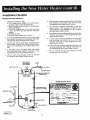
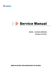
Installation Checklist
BEFORE LIGHTING
THE PILOT:
1. Check the gas lines for leaks.
a. Use a soapy water solution. DO NOT test for
gas leaks using a match or open flame.
b. Brush the soapy water solution on all gas pipes,
joints and fittings.
c. Check for bubbling soap. This means you have
a leak. Turn "OFF" gas and make the necessary
repairs.
d. Recheck for leaks.
e. Rinse off soapy solution and wipe dry.
6. Is there proper clearance between the water heater
and anything
that might
catch fire? See the
"Locating the New Water Heater" section.
7.
Do you have adequate ventilation
so that the
water
heater
will
operate
properly?
See
"Combustion
Air and Ventilation"
in the "Locating
the New Water Heater" section.
8. Is the draft hood vent piping properly secured? See
"Venting" instructions in the "Installing the New
Water Heater" section.
2. Is the new temperature-pressure relief valve properly installed and piped to an adequate drain? See
"Temperature-Pressure Relief Valve" section.
3. Are the cold and hot water lines connected to the
water heater correctly? See "Water Piping" instructions in the "Installing the New Water Heater" section.
9. Is there proper clearance between the vent pipe
and anything that might catch on fire? See
"Venting" instructions in the "Installing the New
Water Heater" section.
10. Is the vent pipe properly sloped and does the vent
terminate outdoors? See "Venting" instructions
in
the "Installing the New Water Heater" section.
4. Is the water heater completely filled with water?
See "Filling the "Water Heater" instructions in the
"installing the New Water Heater" section.
11. Do you need to call your gas company
the gas pipe and its hookup?
5. Will a water leak damage anything? See the
"Locating the New Water Heater" section.
VENT PIPE TO
OUTDOORS
OR CHIMNEY
UNION
COLD
SHUTOFF VALVE
TEMPERATURE-PRESSURE
RELIEF VALVE
DRAFTHOOD
/
MODEL
GAS SUPPLY
DISCHARGE LINE
(Do not cap or plug)
SHUTOFF VALVE
TEE
DRAIN
DRIP
(SEDIMENT TRAP)
i-
VALVE
6 INCH AIR GAP
PIPE CAP
FLOOR DRAIN
Figure 11 1
13
RATING
PLATE
to check
WARNING
BEFORE LIGHTING
[PROPANE
(L.P.) GAS WATER
HEATERS]: Propane (L.P.) gas is heavier than air.
Should there be a leak in the system, the gas will settle
near theground;
Basements, crawl spaces, skirted
areas under mobile homes (even when ventilated),
closets and areas below ground level will serve as
pockets for the accumulation
of this gas. Before
attempting to light or relight the water heater's pilot or
turning on a nearby electrical light switch, be absolutely sure there is no accumulated gas in the area. Search
for odor of gas by sniffing at ground level in the vicinity of the appliance, if odor is detected, follow the steps
indicated at "For Your Safety" on the cover page of this
manual, then leave the premises.
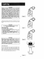
Figure 6 ]
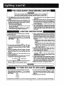
Lighting and operating instructions are located on front of
the water heater, above or to one side of the gas control
valve.
WARNING
AN ODORANT
IS ADDED TO THE GAS USED
BY THIS WATER HEATER.
FOR YOUR SAFETY
IF YOU SMELL GAS:
1. Do not try to light any appliance.
2. Do not touch any. electrical switch; do not use any
phone in your building.
3. Immediately
call your gas supplier from a neighbor's
phone. Follow the gas supplier's instructions.
4. If you cannot reach your gas supplier, call the fire
department.
I Figure 7 ]
WARNING
DO NOT force the gas control knob. Use only your
hand to push it down to light the pilot, or to turn it to
"ON", "OFF" or "PILOT". Never use a tool such as a
lever, wrench or pliers. Do not hit or damage the knob.
A damaged knob may result in an exl_iosion and
serious injury. If you have problem turning the knob,
call the gas supplier immediately.
I Figure 8
CHECK FOR LEAKS
INNER
DOOR
Be sure to check all your gas pipes for leaks before lighting your water heater. Use a soapy water solution, not a
match or open flame. Check the factory gas fittings after
pilot is ]it and gas control knob is still in "PILOT" position.
Then, check the fittings when the main burner is turned
"ON". Use a soapy water solution for this, too.
OUTER
[
I4
Figure 9
DOOR
I
iiii i
,
FOR YOUR
I I
SAFETY
READ
BEFORE
LIGHTING
If you do not follow these instructions exactly, a fire or explosion
, may result causing propertyWARNING
damage, personal injury or loss of life. I
A. This appliancehasa pilot whichmust be lightedby
hand.Whenlightingthe pilot,follow theseinstructions
exactly.
B. BEFORELIGHTINGsmellall aroundthe appliancearea
for gas. Be sure to smell nextto the floor because
somegasisheavierthanair andwillsettleon thefloor.
WHATTO DOIF YOUSMELLGAS
• Do nottryto lightanyappliance.
• Do not touch any electricswitch; do not use any
phonein yourbuilding.
• Immediatelycallyourgas supplierfroma neighbor's
phone.Followthegassupplier'sinstructions,
LIGHTING
NOT FORCE,
4.Turngascontrolknobclockwise_'_
to "OFF" position. Knob cannotbe turned from "PILOT" to "OFF"
unlessknobis depressedslightly.DO NOT FORCE.
(Figure6)
5.Wait five (5) minutesto clear out anygas. If you then
smellgas, STOP!Follow"B" in the safetyinformation
above on this label. If you don'tsmell gas, go to the
nextstep.
6. Remove(or open) inner door locatedbelow the gas
controlunit.(Figure9)
7. Find piloHollowmetaltube fromgas control.The pilot
islocatedon therighthandsideof theburner.
BURNER
D_
iNSTRUCTiONS
1.STOP!Readthesafetyinformationaboveon thislabel.
2. Removeouterdoor.
3. Set the thermostatto lowest setting by turning the
watertemperature
dial clockwise,(f'_) to its lowest
temperaturesetting(witharrowon dial)as shown.DO
PILOT
C.
° If you cannotreachyour gas supplier,call the fire
department.
Useonlyyourhandto pushin or turnthegas control
knob.Neveruse tools.If the knobwill not pushin or
turnby hand,don'ttry to repairit, calla qua,fledservicetechnician.Forceor attemptedrepairmay result
in a fire or explosion.
Do not use this applianceif anypart has been under
water.Immediatelycall a qualifiedservicetechnician
to inspectthe applianceandto replaceany partofthe
controlsystemand any gas controlwhichhas been
underwater,
_THERMOCOUPLIF.
8. If youdon'tsmell_
gas,turnknobon gascontrolcounter
clockwise_
to "PILOT"position.(Figure7)
9, Push in control knob all the way and hold down.
immediatelylightthe pilot with a match.Continueto
hold controlknob in for aboutone (1) minuteafter
the pilot is lit. Releaseknoband it will pop backup.
Pilotshouldremainlit. If it goes out, repeatsteps3
through8.
= If knobdoes not popup when released,stop and
immediatelycall your servicetechnicianor gas
supplier.
. If the pilot wilt not stay lit after several tries
depressand turnthe gascontrolknobclockwise
_,_
to "OFF"and callyourservicetechnician
or gas supplier.
(Figure6)
10. Replace(or close) innerdoor.Replaceouterdoor if
doordoes not covergas controlon/offknobor temperatureadjustmentknob.(Figure9)
11. At armslengthaway,turngascontrolknobcounterclockwise _#_)_ to the full "ON" position.
WARNING Do not use gas control knob to regulate gas flow, (Figure8)
12. At arms lengthaway,set the thermostatto desired
setting.Themark( V ) HOTindicativeofapproximate
120°F is preferredstarting point.Some local laws
may requirea lowerstartingpoint.If hotterwateris
desired,seeinstructionmanualand"warning" below.
13.Replacetheouterdoorif notreplacedin step10.
WARNING
Hotter waterincreasesthe risk of scald injury.Beforechangingtemperaturesettingsee
instructionmanual. I
TO TURN
OFF (;;AS TO APPLIANCE
1. Set the thermostatto lowest settingby turningthe
watertemperaturedial clockwise(_)
to its lowest
temperaturesetting(witharrowon dial)as shown.DO
2. Turngascontrolknobclockwise_
1 to "OFF"posi
t/on. Knobcannotbe turnedfrom "PILOT"to "OFF"
unlessknobis depressedslightly.DO NOT FORCE.
(Figure6)
3. Replaceouterdoor(if removed).
NOT FORCE,
Manufactured
underUSPatentNo,'s4,447,377
& 4,527,543;
Canadian
PatentNo.1,151,480
andotherCanadian
Patents
Pending.
I5
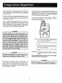
Due to the nature of the typical gas water heater, the
water temperature in certain situations may vary up to
30°F higher or lower at the point of use such as, bathtubs,
showers, sink, etc.
This means that
set at the mark
temperature
at
150°F or as low
The thermostat of this water heater hasbeen factory set at
its lowest position, to reduce the risk of scald injury. It is
adjustable and must be reset to the desired temperature
setting. Read all warnings in the instruction
manual and
on the water heater before proceeding
when the temperature adjustment dial is
approximating
120 ° F, the actual water
any hot water tap could be as high as
as 90°F.
Turn the water temperature dial clockwise ( Z_"_k) to
decrease the temperature, or counterclockwise ( _
)
to increase the temperature.
Any water heater's intended purpose is to heat water. Hot
water is needed for cleansing, cleaning, and sanitizing
(bodies, dishes, clothing).
Hot water will present a scald
hazard. Depending on the time element, and the people
involved (normal adults, children, toddlers, elderly, infirm,
etc.) scalding may occur at different temperatures.
WARNING
HOTTER
WATER CAN SCALD: Water heaters are
intended to produce hot water. Water heated to a temperature which will satisfy clothes washing, dish washing, and other sanitizing needs can scald-and permanently injure you upon contact. Some people are more
likely to be permanently injured by. hot water than others. These iiiclude the elderly, chddren, the infirm, or
physically/mentally
handicapped. If anyone using hot
water in your home fits into one of these groups or if
there is a local code or state law requiring a certain
temperature water at the hot water tap, then you must
take special, precautions, in addition, to .using the lowest possible temperature setting that satisfies your hot
water needs, some type of tempering device, such as a
mixing valve, should be used at the hot water taps used
by these people or at the water heater.
HOT-Is
a thermostat
setting of approximately
120°F, which will supply hot water at the
most economical
temperatures.
A-Is a thermostat
t 30°F.
setting of approximately
B-Is a thermostat
setting of approximately
140°F. This is the lowest setting for supply of
hot water to dishwashers.
C-Is a thermostat
150°F.
VERY HOT-Is
WARNING
I
Never allow small children to use a hot water tap, or to !
draw their own bath water. Never leave a child or handicapped person unattended in a bathtub or shower.
I
setting
of approximately
a thermostat setting of 160°F. It is recommended that the dial be set lower whenever
possible.
NOTE: Residential gas-fired water heaters will not supply
sanitizing hot water for dishwashers.
WARNING
The Consumer
Product
Safety
Commission
has
recommended
as a practical matter, water temperatures of
130°F or lower in a gas water heater. Some states have a
requirement for a lower setting. If you need hotter water,
follow directions for temperature adjustment, but beware
of the warnings in this section.
!
Should overheating occur or the gas supply fail to shut off, !
turn "OFF" the manual gas control valve to the appliance.
]
16
Start Up Conditions
CONDENSATION
The water within the water heater tank expands as it is
heated and increases the pressure of the water system. If _
the relieving point of the water heater's temperature-pressure relief valve is reached, the valve will relieve the
excess pressure. The temperature-pressure relief valve is
not intended for the constant relief of thermal expansion.
This is an unacceptable condition and must be corrected.
Whenever the water heater is filled with cold water, a certain amount of condensation will form while the burner is
on. A water heater may appear to be leaking when in fact
the water is condensation. This usually happens when.;
a. When a new water heater is filled with cold water for
the first time.
b. When gas burns and water vapor is produced in
water heaters; particularly high efficiency models
where flue temperatures are lower:
c. When you use large amounts of hot water in a short
time and the i'efill water is very cold.
Moisture from the products of combustion condense on
the cooler tank surfaces and form drops of water which
may fall onto the burner or other hot surfaces to produce
a "sizzling" or "frying" noise.
It is recommended that any devices installed which could
create a closed system have a by-pass and/or the system
have an expansion tank to relieve the pressure built by
thermal expansion in the water system. Expansion tanks
are available for ordering through the Sears Service
Center. Contact the local water supplier and!or the Sears
Service Center for assistance in controlling these situations.
Excessiv_ condensation can cause pilot outage due to
water runffing down the flue tube onto the main burner
and putting o,ut the pilot.
STRANGE
Possible noises due to expansion and contraction of some
metal parts during periods of heat-up and cool-down do
not represent harmful or dangerous conditions.
Condensation causes sizzling and popping with the burner area during heating and cooling periods and should be
considered normal. See "Condensation" in this section.
Because of the suddenness and amount of water, condensation water may be diagnosed as a "tank leak". After the
water in the tank warms up (about 1-2 hours), the condition should disappear:
Do not assume the water heater is leaking until there has
)een enough time for the water in the tank to warm up.
An undersized water heater will cause more condensation. The water heater must be sized properly to meet the
family's demands for hot water including dishwashers,
washing machines and shower heads.
Operational
Excessive condensation may be noticed during the winter
and early spring months when incoming water temperatures are at their lowest.
Conditions
SMELLY WATER
In each water heater there is installed at least on anode
rod (see parts section) for corrosion protection of the tank.
Certain water conditions
will cause a reaction between
this rod and the water. The most common complaint associated with the anode rod is one of a "rotten egg smell".
This odor is derived from hydrogen sulfide gas dissolved
in the water. Tile smell is the result of four factors which
must all be present for the odor to develop:
a. a concentration
of sulfate in the supply water.
b. little or no dissolved oxygen in the water.
c. a sulfate reducing bacteria within the water heater.
(This harmless bacteria is non-toxic to humans.)
d. an excess of active hydrogen
in the tank. This is
caused by the corrosion
protective
action of the
anode.
Good venting is essential for a gas fired water heater to
operate properly
as well as to carry away products
of
combustion
and water vapor.
SMOKE/ODOR
It is not uncommon to experience a small amount of
smoke and odor during the initial start-up. This is due to
burning offof oil from metal parts, and will disappear in a
short while.
THERMAL
SOUNDS
EXPANSION
Water supply systems may, because of high .line pressure,
frequent cut-offs, the effects of water hammer and others,
have installed devices such as pressure (educing valves,
check valves, back flow preventers, etc...to control these
types of problems. When these devices are not equipped
with an internal by-pass, and no other measures are
taken, the devices cause the water system to be closed. As
water is heated, it expands (thermal expansion) and
losed systems do not allow for the expansion of heated
water.
Smelly water may be eliminated or reduced in some
water heater models by retJlacing the anode(s) with one of
less active material/and
then chlorinating the water
heater tank and all hot water lines. Contact the local
water heater supplier for further information concerning
an Anode Replacement
Kit #9001453
and this
Chlorination Treatment.
17
NOT
SMELLY WATER (cont'd)
.
FAUCETS
gas shut off valve
WARNING
knob must be turned to the "ON"
5. The temperature adjustment dial may be set too
See the "Temperature Regulation" section.
6. The gas company can check the gas input to see if
correct. An underfired water heater will not heat
as quickly.
7. Look for leaking or open hot water faucets. Make
all are closed.
8. The cold water inlet temperature may be colder d_
the winter months, it will take longer to heat the
and seem like less hot water.
9. If you cannot find what
Center.
TEMPERATURE
to be sure
If the pilot is not lit, follow the "Lighting" instruct
in this manual or located above the gas control v
on the water heater to relight the pilot. If the
was extremely hot and is now cold, the high limit !
ty temperature shut off may have put out the bu
and pilot.
The gas control
know valve
mus
changed.
4. The gas control
tion.
HYDROGEN GAS: Hydrogen gas can be produced in a
hot water system that has not been used for a long period of time (generally two weeks or more). Hydrogen gas
is extremely flammable
and explosive. To prevent t_e
possibillty of injury under these conditions, we recommend the hot water faucet be opened for several minutes at the kitchen sink before any electrical appliances
which are connected to the hot water system are used
(such as a dishwasher or washing machine). If h)tdrogen
gas is present, there will probably be an unusual sound
similar to air escaping through the pipe as the hot water
faucet is opened. There must be no smoking or open
flame near the faucet at the time it is open.
HIGH
WATER
2. Check the pilot flame. It may have gone out. All n
els have an opening behind the outer door for vie\
the pilot.
Do not remove the anode leaving the tank unprotected.
By doing so, all warranty on the water heater tank is
voided.
WATER
OR NO HOT
1. Check the manual
open.
If the smelly water persists after the anode replacement
and chlorination
treatment, we can only suggest that continuous chlorination
and filtering conditioning
equipment
be considered to eliminate the water problem.
"AIR" IN HOT
ENOUGH
WATER
SHUT OFF SYSTEM
This water heater is equipped with an automatic gas shut
off system. This system works when high water temperatures are present. It turns "OFF" the entire gas supply to
the water heater. The high temperature
shut off is built
into the gas control valve. It is non-resettable.
If the high
temperature shut off activates, the gas control valve must
be replaced. Contact the Sears Service Center.
IS TOO
is wrong, call the Sears Ser
HOT
I. The temperature adjustment dial may be set too t"
See the "Temperature Adjustment" section.
NOTE: A period of time is necessary after an adj
ment has been made for the water temperatur,
reach the new temperature setting.
2. If lower temperature settings will not lower
temperature, call the Sears Service Center.
.WARNING
Should overheating occur or the gas supply fail to shut
off, turn "OFF" the manual gas control valve to the
appliance,
I8
the w
Venting
System
Inspection
At least once a year a visual inspection should be made of
the venting system. You should look for:
I. Obstructions which could cause improper venting. The
combustion and ventilation air flow must not be
obstructed.
2. Damage or deterioration which could cause improper
venting or leakage of combustion products.
3. Rusted flakes around top of water heater.
WARNING
WARNING
Soot build-up indicates a problem that requires correction before further use. Turn "OFF" gas to water heater
and leave "OFF" until repairs are macle, because failure
to correct the cause of the sooting can result in a fire
causing DEATH, SERIOUS BODILY INJURY, OR PROPERTY DAMAGE.
Be sure the ventpiping is properly connected to prevent escape of dangerous flue gasses which could
causedeadly asphyxiation.
WARNING
I
Burner Cleaning
1
I sent
Obstructions
serious health
and deteriorated
risk or asphyxiation.
vent systems may pre- 1
In the event your burner needs cleaning, use the following
instructions:
WARNING
Chemical vapor corrosion of the flue and vent system
nay occur ifalr for combustion contains certain chemca/vapors. Spray can propellants, cleaning solvents,
'efrigerator and air conditioner refrigerants, swimming
)ool chemicals, calcium and sodium chloride, waxes,
)leach and process chemicals are typical compounds
which are potentially corrosive.
If inspection of the burner shows that cleaning is required,
turn the gas control knob clockwise (/'-_)
to the "OFF"
position, depressing slightly.
NOTE: The knob cannot be turned from "PILOT" to "OFF"
unlessknob is depressedslightly. DO NOT FORCE.
Loose deposits on or around the burner can be removed
by carefully using the hose of a vacuum cleaner inserted
through the access door of the water heater. If the burner
needs to be removed for additional cleaning, call the Sears
Service Center to remove and clean the burner and correct
the problem that required the burner to be cleaned.
WARNING
If after inspection of the vent system you found sooting
or deterioration, something is wrong and a Sears
Service Technician must he called in, the problem corrected, and the flue and venting cleanedor replaced
before resumingoperation on the water heater.
Housekeeping
Vacuum around base of water heater for dust, dirt, and
lint on a regular basis.
WARNING
Burner Inspection
INSTALLED IN SUITABLE AREA: To insure sufficient
ventilation and combustion air supply, proper clearances from the water heater must be maintained. See
"Locatin_ the New Water Heater" section. Combustible
materials such as clothing, cleaning materials, or
flammable liquids, etc. must not be placed againstor
adjacent to the water heater which can cause a fire.
At least once a year a visual inspection should be made of
the main burner and pilot burner. The drawing is for your
reference.
You should check for sooting which is not normal and
will impair proper combustion.
19
r!ll,i
Temperature-Pressure
Relief
Draining
Valve Operation
The water heater should be drained if being shut down
during freezing temperatures. Also periodic draining and
cleaning of sediment from the tank may be necessary.
The temperature-pressure relief valve must be manually
operated at least once a year.
I
1. Turn the gas control knob to the "OFF" position.
2. CLOSEthe cold water inlet valve to the water heater.
3. OPEN a nearby hot water faucet and leave open to
allow for draining.
4. Connect a hose to the drain valve and terminate to an
adequate drain.
5. OPEN the water heater drain valve to allow for tank
draining.
NOTE: If the water heater is going to be shut down
and drained for an extended period, the drain valve
should be [eft open with hose connected allowing
water to terminate to an adequate drain.
6. Close the drain valve.
7. Follow instructions in the "Filling The Water Heater"
section.
8. Follow the lighting instructions in the "Lighting" section
to restart the water heater.
TEMPERATURE-PRESSURE
DRAIN
LINE
_"
Drain Valve Washer
Replacement
WARNING
When checking the temperature-pressure relief valve
operation, make sure that (1) no one is in front of or
around the outlet of the temperature-pressure relief
valve dischargeline, and (2) that the water manually discharged will not causeany property damage becausethe
water may be extremely hot.
if after manually operating the valve, it fails to completely reset and continues to release water, immedlately
closethe cold water inlet to the water heater, follow the
draining instructions,and replace the temperature-pressure relief valve with a new one.
NOTE: For replacement, use a '%_"x '%4"x ½" thick washer
available at your nearest hardware store. For ordering
replacement washers,refer to the "Repair Parts"section.
t. Turn "OFF" gas supply to water heater.
2. Follow "Draining" instructions.
3. Turning counter clockwise, remove the hex cap below
the screw handle.
4. Remove the washer and put the new one in place.
5. Screw the handle and cap assembly back into the drain
valve and retighten using a wrench. DO NOT OVER
TIGHTEN.
6. Follow instructions in the "Filling The Water Heater"
section.
7. Check for leaks.
8. Follow the lighting instructions in the "Lighting" section
to restart the water heater.
Failure to install and maintain a new properly listed temperature-pressure relief valve will release the manufacturer from any claim which might result from excessive temperature or pressure.
HANDLE AND
CAP ASSEMBLY
:WASHER
WARNING
If the temperature-pressurerelief valve on the appliance
weeps or discharges periodically, this may be due to
thermal expansion. Your water heater may have a check
valve installed in the water line or a water meter with a
checkvalve. Consultthe SearsService Center for further
information. Do not plug the temperature-pressure
relief valve.
Service
If a condition persists or you are uncertain about the
operation of the water heater, let a qualified person check
it out. Cal! the SearsService Center.
2O
Usethisguideto checka "Leaking_'water heater. Many
suspected "Leakers" are not leaking tanks. Often the
source of the water can be found and corrected.
CAUTION
Read this manual first. Then before checking the water
heater make sure the gas supply has been turned "OFF!',
and never turn the gas "ON" l_efore the tank is completely full of water.
CAUTION
Never use this water heater unless it is completely filled
with water. To prevent damage to the tank, the tank must
be filled with water. Water must flow from the hot water
faucet before turning "ON" gas to the water heater.
If you are not thoroughly
familiar with gas codes your
water heater, and safety practices,
contact
the Sears
Service Center to check the water heater.
O
Water at the draft hood is water vapor which has
condensed out of the combustion products. This is
caused by a problem in the vent. Contact the Sears
Service Center.
O
Condensation
may be seen on pipes in humid
weather or pipe connections may be leaking.
O
*The primary
Q
Small amounts of water from temperature-pressure
relief valve may be due to thermal expansion or high
water pressure in your area.
anode rod fitting may be leaking.
temperature-pressure
@ *The
ing at the tank fitting.
relief valve may be leak-
from a drain
@ Wafer
opened slightly.
may be due to the valve
valve
® *The drain valve may be leaking at the tank fitting.
products contain water vapor which can
€I1Combustion
condense on the cooler surfaces of the tank. Droplets
form and drip into the fire or run on the floor. This is
common at the time of startup after installation and
when incoming water is cold.
O
Water in the water heater bottom or on the floor may
be from condensation,
loose connections,
or the
relief valve, DO NOT replace the water heater until
a full inspection of all possible water sources is made
and necessary corrective steps taken.
Leakage from other appliances, water lines, or
grounaseepage should also be checked.
*To check where threaded portion enters tank, insert Q-Tip between jacket opening and fitting. If cotton is wet, follow
Draining instructions and then remove fitting. Put pipedope or teflon tape on the threads and replace. Then follow "Filling
the Water Heater" instructions in the "Installing the New water Heater" section.
21
/
I
J
qD
Ii
-
\
i:E 11'_
¢o
._
m_m
00_
ua
u_
o_
_m
zO
22
'el
E
_
C
c
O
O
--_o
_
0
O
i t",t
=
,{.-
o
c
c
c
I
0
O
O
O
g_
>.._¢N P_
P-.
©
©
o
C
c
c
c9
O
O
O
_-_ <
<
o
0
cco
o8
JZJs
pl °
o
c
oh
o_
L_
L_ CC
¢_ ¢-,
_S
0
C
co
99
m
,..,ec_.O
Pq
o
o
m
crl
_m
O_ 0 _
_
t
t'l
O
(..,.q tt'3
¢'q _N
I'-,. C
¢.4
o
o
o
0
>.t'-
_
>'=,_
M-
0
,,_zz
_e-_
_
¢,q
SiR
0
0
_° O
¢q
o
o
o
r,,t
o
o
o
i
C
,T'e,l
t-..
o
O
_
®L._
I-.-,-
.J
L¢) CO
0
I
,T'-tl
-I°
L_
L_ CO
,'_ ¢'4
o
OU
zl +_, _
{'-4 b..
1
m
,.4
t"-,4
i"-..
i
t_
e,l
o
O_ Oh
0
o
o
0_
e_
_
_
N_
L0
E
_o _
_o
o
_.__
_o._._
>
o
s_
_
5_
_
_-o
o
_|_
23
_ ._
a"
m
5z
_
.1.1
i
._
_ _..-_
_-,_
r_Z
!
MMMM
.-
o
i
.
i_.r"
-_E
e-
1..i.1
k.,)
o
,', _ u
A _;e_m
_
0
......................................................................
About
iiiimll!
ON INSTALLATIONS NOT MADE BY SEARS AUTHORIZED CONTRACTORS:
1. Your Searswarranty applies to the product only.
2. Searsdoes not warrant the installation.
3. A charge will be made on service calls due to poor or
incomplete installation. These include:
a. Adjusting thermostat.
b. Lighting pilot.
c. Leaks in pipes or fittings.
Your Warranty
Some warranties say that you must drain the tank once a
month. •Yourtank will last longer if you do this. Your Sears
warranty is good whether you drain the tank often or not.
We include a drain valve because:
1. Many plumbing codes require a drain valve.
2. "Your water heater will continue to heat efficiently, if a
small amount of water is drained each month. THE
PRICE OF YOUR
WATER
HEATER
DOES NOT
INCLUDE
A FREE CHECKUP
SERVICE CALL. ON
WATER HEATER INSTALLATIONS
ARRANGED
BY
SEARS, Sears warrants the installation.
This manual is in non-technical language. It may help
you avoid the cost of a needless service call. Many service calls really aren't needed. Such as when:
t.• The
The gas
pilotisisturned
out. "OFF".
3. A gas or water leak is due to loose pipe or connections.
FULL ONE YEARWARRANTYON WATERHEATER
For one year from the date of purchase,when your SearsKenmore water heater is installed and operated in accordance
with the information in this Manual Searswill:
1. Repairdefects in material or workmanship in this water heater,free of charge.
2. Furnish and install a new current model water heater of equal capacity and quality, free of charge, if a leak occurs in
the tank.
LIMITEDWARRANTYON TANKSTHAT LEAK
After one year and through 6 years from the date of purchase,if a Jeakoccurs in the tankfSears will furnish a new current model water heater of equal capacity and quality. You will be chargedfor installation.
SomeStatesare imposing energy efficient standardson water heaters.Such standardsmay prohibit Searsfrom replacing
some water heaters with others of equal capacity and quality. If your State prohibits Searsfrom replacing your water
heater with one of equal capacity and quality, should you need replacement under the warranty; Searswill replace your
water heaterwith one meeting the required standardsunder the following conditions:
1. During the Ful! One YearWarranty, the replacementwill be provided free of charge.
2. During the Limited Warranty, you will be (2hargedthe difference between the current price of the replacement water
heater meeting the requited standardsand a water heater in Sears' Line available in other Stateswhich is of equal
capacity and quality to your water heater. In addition, you will be charged for installation asstated in the warranty.
LIMITED WARRANTYON PARTSFAILURE
For a period of 3 years from the date of purchase;when your SearsKenmore water heater is installed and operated in
accordance with the information in this Manual; if a part fails due to a defect in materials or workmanship; Searswil!
furnish a replacement part free of charge. You will be charged for instaJlation.
If the water heater is subjected to commercial, institutional, industrial or other non-residential use, the above warranty
coverage for tanks that leak is effective for 2 years from the date of installation.;The above partswarranty is effective for
t year from the date of installation.
To obtain warranty service, SIMP[Y CONTACT THE NEARESTSEARSSERVICECENTERIN THE UNITED STATES."This
warranty applies only while this product is in use in the United States.!'
This warranty gives you specific legal rights and you may also have other rights which vary from stateto state.
"SEARS, ROEBUCK AND CO., Dept. 731-CR-W, Sears Tower, Chicago, IL 60684"
Sears Installation Policy
Sears Installation
All installation labor arranged by Sears shall be performed
in a neat, workmanlike manner in accordance with generally accepted trade practices. Further, all instal]atlons shall
comply with all local laws, codes regulations and ordinances. The customer shall also be protected, during
installation, by insurance relating to property damage,
Worker's Compensation and Public Liability•
In addition to any warranty extended to you on the Sears
merchandise involved, which warranty becomes effective
the date the merchandise is installed should the workmanship of any Sears arranged installation prove faulty within
one year, Sears will, upon notice from you, cause such'
faults to be corrected at no additional cost to you.
Warranty
If you want this water heater professionally installed, contact your Sears Salesperson. He will arrange for prompt, quality
installation by Searsauthorized contractors.
!
F642-5489
0291236-00
24
Sears_Roebuck and Co., Chicago, IL 60684 U.S.A.