1
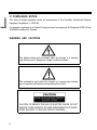
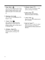
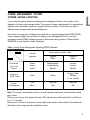
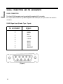
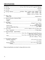
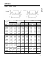
SyncMaster 3
36 Cm ( 14” Diagonal )
Basic:CQA4147
CQA4147L
User’s Manual
COLOR DISPLAY UNIT
TABLE OF CONTENTS
INTRODUCTION
FOREWORD
2
FEATURES
2
FCC, IC AND SAFETY INFORMATION
FCC INFORMATlON..
IC COMPLIANCE NOTICE
3
4
WARNING AND CAUTIONS
4
SAFETY TIPS
5
OPERATING GUIDE
CONNECTING TO YOUR COMPUTER
CONTROL LOCATIONS AND FUNCTIONS
6
7
POWER MANAGEMENT SYSTEM
SIGNAL CONNECTlONS AND PIN ASSIGNMENT
TROUBLESHOOTlNG
SPEClFlCATlONS
9
0
11
12
APPENDIX
SIGNAL TIMING CHART
13
Note
— IBM, VGA, XGA, XGA II and PS/2 are registered trademarks of International Business Machines
Corporation
— Super-VGA(SVGA) and VESA are registered trademarks of the Video Electronics Standards Association.
1
INTRODUCTION
FOREWORD
First, we would like to thank you for your
purchase of this monitor. This monitor is 14
inch, high resolution, color display monitor.
This manual covers the use, and points of
caution, when operating this monitor.
Please take the time to read this manual so
that you will obtain the best performance
and most use from your monitor. After
reading the manual, store it in a safe place
for future reference.
The contents of your monitor carton should
contain:
- CQA4147, CQA4147L monitor
- Tilt and swivel stand
- This manual
- Power cord
- 9-15 pin signal cable
MPR II compliance
Model numbers with a “L” suffix comply with
SWEDAC (MPR II) recommendations for
reduced electric and magnetic fields.
FEATURES
36 cm (14”) [ 33.5 cm (13.2”) visual] high
performance CRT.
-Available in 0.28 mm dot pitch
Automatically scans frequencies from
31.47KHz / 70Hz, 31.47KHz / 60Hz,
35.52KHz / 87Hz, 37.86KHz / 72.8Hz,
35.16KHz / 56Hz, 37.88KHz / 60.3Hz.
37.50KHz / 75Hz.
Compatible with a wide variety of video
standards including VGA, IBM 8514/A
(XGA), and Super-VGA.
Supports VESA flicker-free modes.
Size and position controls are located up
front for easy and accurate adjustment.
The optional tilt and swivel stand may be
attached to provide a variety of viewing
angles, or not attached if limited
workspace is a consideration.
Power supply operates on AC 100 - 240
Volt 60/50Hz for use all over the world.
Your display has been designed to
operate on all power systems, including
“IT” power systems.
Power Management System
Power management circuit, when
signaled by the computer system, will
reduce power consumption when the
computer system is not in use.
2
FCC, IC AND SAFETY INFORMATION
FCC INFORMATION
INSTRUCTIONS TO USER
INFORMATION TO USER
Note: This equipment has been tested and
found to comply with the limits for a Class B
digital device, pursuant to Part 15 of the FCC
Rules. These limits are designed to provide
reasonable protection against harmful
interference in a residential installation. This
equipment generates, uses and can radiate
radio frequency energy and, if not installed
and used in accordance with the instructions,
may cause harmful interference to radio
communications. However, there is no
guarantee that interference will not occur in
a particular installation. If this equipment
does cause harmful interference to radio or
television reception, which can be
determined by turning the equipment off and
on, the user is encouraged to try to correct
the interference by one or more of the
following measures:
Changes or modifications not expressly
approved by the party responsible for
compliance could void the user’s authority to
operate the equipment.
If necessary, consult your dealer or an
experienced radio/television technician for
additional suggestions. The user may find the
following booklet helpful, prepared by the
Federal Communications Commission. “How
to Identify and Resolve Radio/TV
Interference Problems” This booklet is
available from the U.S. Government Printing
Office, Washington, D.C.20402, Stock
number 004-000-00345-4.
Reorient or relocate the receiving
antenna.
Increase the separation between the
equipment and receiver.
Connect the equipment into an outlet on
a circuit different from that to which the
receiver is connected.
Consult the dealer or an experienced
radio / TV technician for help.
WARNING
User must use properly shielded power
supply cord and interface cables to comply
with the requirements of the FCC.
Provided with this monitor is a detachable
power supply cord with IEC320 style
terminations. It may be suitable for connection
to any UL Listed personal computer with
similar configuration. Before making the
connection insure that the voltage rating of the
computer convenience outlet is the same as
the monitor and that the ampere rating of the
computer convenience outlet is equal to or
exceeds the monitor current rating.
For 120 Volt applications use only UL Listed
Detachable Power cord with NEMA
configuration 5-15P type ( parallel blades )
plug cap. For 240 Volt applications use only UL
Listed Detachable power supply cord with
NEMA configuration 6-15P type ( tandem
blades ) plug cap.
3
IC COMPLIANCE NOTICE
This Class B digital apparatus meets all requirements of the Canadian Interference-Causing
Equipment Regulations of ICES-003.
Cet appareil numérique de la Classe B respecte toutes les exigences du Règlement ICES-003 sur
le Matériel brouilleur du Canada.
WARNING AND CAUTIONS
The lightning flash and arrowhead within the triangle is a warning
sign alerting you of “dangerous voltage” inside the product.
The exclamation point within the triangle is a warning sign alerting
you of important instructions accompanying the product.
CAUTION: TO REDUCE THE RISK OF ELECTRIC SHOCK, DO NOT
REMOVE COVER (OR BACK). NO USER SERVICEABLE PARTS INSIDE.
REFER SERVICING TO QUALIFIED SERVICE PERSONNEL.
4
SAFETY TIPS
1.
Make sure the voltage designation on
your monitor corresponds to local
electrical supply before connecting the
AC power cord to an outlet.
2.
To avoid electric shock, never touch the
inside of the monitor. Only a qualified
technician should open the monitor's
case.
3.
Never use your monitor if the power cord
has been damaged. Do not allow
anything to rest on the power cord, and
keep the cord away from where people
will walk on it.
4.
Be sure to hold the plug, not the cord,
when disconnecting the monitor from an
electric socket.
5. Openings in the monitor cabinet are
provided for ventilation. To prevent
overheating, these openings should not
be blocked or covered. Also, avoid using
the monitor on a bed, sofa, rug, or other
soft surface, because doing so may block
the ventilation openings in the bottom of
the cabinet. If you put the monitor in a
bookcase or some other enclosed space,
be sure that adequate ventilation is
provided.
6.
Never insert anything metallic into the
monitor openings. Doing so may create a
danger of electric shock.
7.
Put your monitor in a location with low
humidity and a minimum of dust. Avoid
places like damp basements or dusty
hallways.
Do not expose the monitor to rain or use
it near water (in kitchens, next to
swimming pools, etc.). If the monitor
accidentally gets wet, unplug it and
contact an authorized dealer
immediately. You can clean the monitor
with a damp cloth when necessary, but
be sure to unplug the monitor first.
9. Place the monitor on a solid surface, and
treat it gently. The screen is made of
glass and can be damaged if dropped or
hit sharply.
10. If your monitor does not operate
normally; in particular, if there are any
unusual sounds or smells coming from it,
immediately unplug it and contact an
authorized dealer.
11. High temperatures can cause trouble.
Don’t try to use your monitor in direct
sunlight, and keep it away from heaters,
stoves, fireplaces and other sources of
heat.
12. Unplug the monitor when it is going to
be left unused for an extended period of
time.
13. Unplug your monitor from the AC outlet
before any service.
14. Install your AC outlet near the monitor
and be sure to be easily accessible.
8.
5
OPERATING GUIDE
CONNECTING TO YOUR COMPUTER
Signal Input
AC Cord Inlet
Power (On/Off)
Power Indicator
This monitor can be connected to any IBM compatible analog display adapter.
Such adapters include VGA, 8514/A, XGA, and the built-in video system of IBM PS/2 computers
and compatibles.
To attach the monitor to your system, use the following instructions:
1.
2.
Turn off the power to the computer.
Insert the AC power cord into monitor
and then into an AC power outlet.
3. Connect the 9-pin side of the signal
cable to the 9-pin D-SUB connector on
the rear side of the monitor.
4.
Before turning on the power to the
monitor and computer, check your
computer’s owner’s manual for
instructions about turning on equipment
connected to the computer. Also, check
for any instructions for your video system
when using a multi-sync monitor. In
some cases, jumper or switch settings
may be required for the video board to
output extended resolution modes.
6.
To turn on the monitor, push the power
switch. The power indicator LED will
light. To turn the monitor off, push the
power switch once again. The power
indicator LED will also turn off.
Connect the 15-pin side of the signal
cable to the video output port of your
video controller.
Note: Please see the connector pin
assignment chart for the video controller
(video controller manual) and the connector
pin assignment chart for the monitor (Page
10 this manual) if the video controller does
not have a standard 15 pin D-SUB connector.
6
5.
CONTROL LOCATIONS AND FUNCTIONS
BEFORE OPERATING THE MONITOR
Please take the time to familiarize yourself with the locations and functions of all the monitor’s
controls so that you can adjust it for the optimum display.
Front View
1. Power Switch (PUSH)
2. Brightness Control
3. Contrast Control
8. Side Pin Control
7. V-Size Control
6. H-Size Control
5. V-Position Control
4. H-Position Control
7
1. Power Switch
Use to turn monitor power on and off. Push
switch once to turn monitor power on. LED
power on indicator will also turn on. Push
switch once again to turn monitor power
off.
2. Brightness Control
Use to adjust the overall brightness of the
displayed image.
3. Contrast Control
Use to adjust the contrast level of the
displayed image. Contrast controls the
difference between dark and light areas of
the displayed image.
4. H-Position Control
Adjust this the control for the proper
horizontal position (centering) of the
display.
8
5. V-Position Control
Adjust this control for the proper vertical
position (centering) of the display.
6. H-Size Control
Adjust this control for the desired
horizontal size (width) of the display.
7. V-Size Control
Adjust this control for the desired vertical
size of the display.
8. Side Pin Control
Adjust this control, to correct the vertical
sides of the display from bowing out
(barrel distortion) or bowing in (pincushion
distortion).
POWER MANAGEMENT SYSTEM
(POWER SAVING FUNCTION)
If your computer system features a display power management function, this monitor, when
signaled, will enter power savings modes. The purpose of power management is to automatically
reduce power consumption when the computer system is inactive. This monitor can enter 3
different power savings modes as described below.
This monitor is energy star compliant when used with a computer equipped with DPMS (VESA)..
If your computer system can not support a display power management function, you may
purchase a optional DPMS software program to have power saving function. Please contact
SAMSUNG or your dealer for detail information.
Table : Display Power Management Signaling (DPMS) Standard
State
Sync
Normal
operation
Power saving function mode
Suspend
Mode
Power-off
Mode
Horizontal
Vertical
Video
Active
Active
Active
Active/Inactive
Inactive/Active
Blanked
Inactive
Inactive
Blanked
Remark
(LED Color)
Green
Orange
Orange, Green
Blinking
(1 sec interval)
70W
(Max.)
Less than
15W
Less than
8W
Power
Consumption
Note: This monitor automatically returns to normal operation state when horizontal and vertical
sync returns.
When you turn power off in power-off mode, LED indicator may continuously blink on-off about
for 2 to 15 seconds.
When power off mode is changed to normal mode in this monitor it takes about 10 seconds until
all function of the image operate completely normal.
9
SIGNAL CONNECTIONS AND PIN ASSIGNMENTS
D-SUB CONNECTOR
The 9 pin D-SUB connector can be used with the supplied 9-15 pin cable.
The 15 pin side connects to any IBM compatible VGA video port, the 9 pin side to the monitor’s
connector.
D-SUB Signal Input (Female Type : Figure)
PIN ASSIGNMENT
1
RED
2
GREEN
3
BLUE
4
H-SYNC
5
V-SYNC
6
GND-R
7
GND-G
8
9
GND-B
GND-SYNC
[ Figure ]
10
SIGNALS
TROUBLESHOOTING
Before calling an authorized service center, please check this troubleshooting chart. Many of the
problems that can occur are easily corrected without the need of a technician.
TROUBLE CONDITION
POSSIBLE CAUSE
CORRECTIVE MEASURE
Image is not displayed.
Is the power cord connected?
Connect the power cord.
Is the power switch ON?
Turn on the power switch.
Is the signal cable properly
Connect the signal cable
connected?
correctly.
Is the Brightness or Contrast
Adjust the Brightness and
adjustment knob turned all the way Contrast to the middle position
to one side?
of their range.
Color of image on screen is
abnormal.
Is there a magnetized item near?
Move the magnetized item away.
Is the pin arrangement of the signal Use a signal connector which
matches the pin arrangement.
connector correct?
Is the signal cable connected
Connect the signal cable
properly?
correctly.
Picture is unstable.
(The displayed image is tearing
or rolling)
Are there signals, which are outside
of the required frequency range?
Is the pin arrangement of the signal
connector correct?
Is the signal cable correctly
connected?
The displayed image is too
small or shifted, and the
controls can’t adjust properly.
Are there signals, which are outside Input signals which are within
the frequency range of the
of the required frequency range?
monitor.
Input signals which are within
the frequency range of the monitor.
Use the signal connector which
matches the pin arrangement.
Connect the signal cable
correctly.
11
SPECIFICATIONS
36 cm (14”) [ 33.5 cm (13.2”) visual], 90° Deflection
Non-Glare
CRT Size
CRT Screen
Dot Pitch
Scanning Frequency
0.28 mm
31.47KHz / 70Hz, 31.47KHz / 60Hz, 35.52KHz / 87Hz.
37.86KHz / 72.8Hz, 35.16KHz / 56Hz,
37.88KHz / 60.3 Hz, 37.50KHz / 75Hz
Display Colors
Analog Input
Maximum Resolution (Interlaced Mode)
Horizontal
Vertical
Input Signal
Video Signal
Separate Sync
Video Band Width (Pixel Time)
Power Supply
Power consumption
Unlimited Colors
1024 Dots
768 Lines
Analog (0.7 Vp-p), Positive
75 Terminated
TTL level Positive or Negative
Max. 45MHz
AC 100 - 240Volt ± 10%, 60 / 50Hz ± 3Hz
70 Watts (Max.)
Dimensions/Weight (Approximately)
Unit
Carton
14.5 x 14.0 x 15.0 inches (H x W x D)/ 23 Ibs 2.4 oz
(368 x 356 x 379.5 mm / 10.5 kg)
18.2 x 18.0 x 15.7 inches (H x W x D) / 27 Ibs 8.9 oz
(462 x 457 x 398 mm / 12.5 kg)
Environmental Considerations
Operating Temperature
Humidity
Storage Temperature
Humidity
Design and specifications are subject to change without prior notice.
12
32°F to 104°F (0°C to 40°C)
10% to 80%
-4°F to 113°F (-20°C to 45°C)
5% to 95%
APPENDIX
SIGNAL TIMING CHART
Vertical
Horizontal
IBM
VESA
VGA1/7OHz VGA2/70Hz VGA3/60Hz XGA/87iHz 640/72Hz 800/56Hz
640x350 720x400
640x480
1024x768 640x480
800/60Hz
640/75Hz
800x600
800x600
640x480
fH (kHz)
31 469
31 469
31 469
35 522
37 861
35 156
37 879
37.500
A µsec
31.778
31.777
31.778
28.151
26.413
28.444
26.400
26.667
B µsec
3.813
3.813
3.813
3.920
1.270
2.000
3.200
2.032
C µsec
1.907
1.907
1.907
1.247
4.064
3.556
2.200
3.810
D µsec
25.422
25.422
25.422
22.806
20.317
22.222
20.000
20.317
E µsec
0.636
0.636
0.636
0.178
0.762
0.667
1.000
0.508
fv (Hz)
70.086
70 087
59.940
86 958
72.809
58 250
60 317
75.000
O msec
14.268
14.268
16.683
11.500
13.735
17.778
16.579
13.333
P msec
0.064
0.064
0.064
0.113
0.079
0 057
0.106
0.080
Q msec
1.907
1.080
1.048
0.563
0.739
0.626
0 607
0.427
R msec
11.122
12.711
15.253
10.810
12.678
17.067
15.840
12.800
S msec
1.176
0.413
0.318
0.014
0.237
0.028
0.026
0.027
25.175
28.322
25.175
44.900
31.500
36.000
40.000
31.500
H. Sync.
Positive
Negative
Negative
Positive Negative
Pos./Neg.
Positive
Negative
V Sync.
Negative Positive
Negative
Positive Negative
Pos./Neg.
Positive
Negative
Clock Fre.
(MHz)
Polarity
Remark
Interlaced
13
U.S.A. :
SAMSUNG ELECTRONICS AMERICA (SEA)
ONE SAMSUNG PLACE LEDGEWOOD
NJ 07852
Tel. : 1-800-SAMSUNG (1-800-726-7864)
Fax-on-Demand for product information :
1-800-229-2239
SPAIN :
SAMSUNG ELECTRÓNICA COMERCIAL
IBÉRICA, S.A. Ciencies, 55-65 (Polígono
Pedrosa) 08908 HOSPITALET DE LLOBREGAT
(Barcelona)
Tel. : (93) 261 67 00
Fax. : (93) 261 67 55
CANADA :
SAMSUNG ELECTRONICS CANADA INC.
7037 Financial Drive Mississauga
Ontario L5N 6R3
Tel. : 1-800-SAMSUNG (1-800-726-7864)
Fax. : (416) 542-1199
UK:
SAMSUNG ELECTRONICS (UK) LTD.
Samsung House, 225 Hook rise south surbiton,
surrey KT6 7LD
Tel. : (0181) 391 0168
Fax. : (0181) 397 9949
GERMANY:
Samsung Electronics GmbH
Daimlerstr. 6 D-61449 Steinbach/Ts.
Tel. : 06171/708-0
Fax. : 06171/75489
<EUROPEAN SERVICE CENTRE & NATIONAL
SERVICE>
Stafford Park 12 Telford, Shropshire, TF3 3BJ
Tel. : (01952) 292 262
Fax. : (01952) 292 033
AUSTRALIA :
SAMSUNG ELECTRONICS AUSTRALIA
PTY LTD
Unit G, 10-16 South Street, RYDALMERE
N.S.W 2116
P.O. BOX 368
Tel. : (02) 638 5200
THAILAND :
SAMSUNG SERVICE CENTER
729-729/1 JSP Tower Rachadapisek RD.,
Bangpongpang, Yannawa, Bangkok 10120
Tel : (662) 2954508-14
Fax : (662) 2954267
ITALIA :
Samsung Electronics ltalia SpA
Via C. Donat Cattin, 5-20063 Cernusco sul
Naviglio (Mi)
Tel. : 167-010740
SOUTH AFRICA :
SAMSUNG ELECTRONICS SOUTH AFRICA
Somerset Office Park 5 Libertas Road
Bryanston South Africa
Tel : (27)-11-463-5678
Fax : (27)-11-463-5215
EPA POLLUTION PREVENTER
“As an ENERGY STAR Partner. SAMSUNG has
determined that this product meets the ENERGY
STAR guidelines for energy efficiency."
CODE NO.:BH68-60023A( Rev. 1.1 )
Printed on the recyclable paper