1
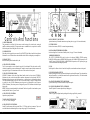
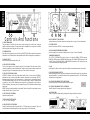
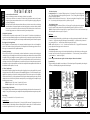
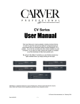
Introduction
Safety Information
CAUTION
RISK OF ELECTRIC SHOCK
DO NOT OPEN
CAUTION: TO REDUCE THE RISK OF ELECTRIC SHOCK
DO NOT REMOVE COVER (OR BACK)
NO USER-SERVICEABLE PARTS INSIDE
REFER SERVICING TO QUALIFIED SERVICE PERSONNEL
The lightning flash with arrowhead
symbol within an equilateral triangle
is intended to alert the user to the
presence of uninsulated"dangerous
voltage" within the product's
enclosure, that may be of sufficient
magnitude to constitute a risk of
electric shock to persons.
The exclamation point within an
equilateral triangle is intended to alert
the user of the presence of important
operating and maintenance (servicing)
instructions in the literature
accompanying the appliance.
Table Of Contents
Introduction ............................................................2
Unpacking and Paperwork.....................................2
Features and Specifications
PX850..............................................................3-4
PX1450............................................................5-6
Controls and Features .........................................7-8
Installation and Operations
Location and General Precautions .....................9
Mechanical Considerations ................................9
Rear Support.......................................................9
Thermal Considerations .....................................9
AC Power Considerations..................................9
Magnetic Leakage Considerations.....................9
Input Wiring .......................................................9
Installation (continued)
Input Sensitivity ...............................................10
Output Wiring...................................................11
Polarity .............................................................11
Bridged Mono...................................................11
Parallel Mono ...................................................11
70V Distribution Systems...........................11-12
Signal Smart Standby Circuit...........................12
Operating Tips......................................................13
Care and Service Assistance ................................13
Configurable Gain Controls.................................14
In Case of Difficulty.............................................15
Warranty Information...........................................16
Accessories......................................................17-18
Congratulations on your purchase of a new Carver Professional Power Amplifier. The PX850 and
PX1450 are designed for any pro audio application. The PX Series is the first line designed and
produced by Carver Professional, a division of Phoenix Gold International, Inc. It combines the Pro
Audio experience and sonic heritage of Carver Professional with the performance, manufacturing
quality and attention to detail that has defined Phoenix Gold International. Thank you for placing
your confidence in Carver Professional and Phoenix Gold. We know your amplifier will provide many years
of dependable service and reliable sound reproduction.
Please read all of this manual, especially the Safety Warnings, before operating your amplifier.
Unpacking and
Paperwork
Carefully unpack the amplifier and keep the original carton and packing materials for future moving, shipment
or long-term storage. After opening the box, please check for any visible signs of damage that were not apparent from the outside of the box. If you do encounter what appears to be concealed damage, please consult your
Carver Professional Dealer before installing the unit.
Important Paperwork
Make sure to save your sales receipt. Your receipt is extremely important to establish the duration of your
Limited Warranty and for insurance purposes. Next, make a note of the serial number which is located on the
back of the amplifier. Record it in the space provided below for convenient reference.
Model: _____PX850_____PX850BR _____PX850SP
____PX1450____PX1450 BR ____PX1450SP
Serial Number: _____________________________
Purchased at: _______________________________
Date: _____________________________________
Finally, take a moment to fill out and return the Warranty Registration Card packed with the amplifier and return
it to Carver Professional. This will allow us to keep you informed about new products as they become available.
2
PX850
• 250W per channel into 8 ohms
•
•
•
•
425W per channel into 4 ohms
525W per channel into 2 ohms
Three connector versions available:
Standard Neutrik™ combi inputs with
Binding Post outputs
BR Version - Barrier Strip inputs and outputs
SP Version - Neutrik™ combi inputs with
Neutrik™ Speakons™ and
Binding Post outputs
Independent 41 detent Level Controls for CH1 & CH2
Externally configurable for Parallel Mono mode to
operate both channels with a mono signal
Externally configurable for Bridged Mono mode to
combine the power of both channels into a higher
powered mono channel
• Externally configurable input sensitivity @ 0.775V,
1.5V or fixed +28dB gain
• Protection circuitry includes DC Fault, Thermal,
and Short Circuit
Power
Ready, Signal Present, Clip, Protect,
•
Thermal and Standby indicators for each channel
• Variable Speed Fan
• Front or Rear Gain Controls (field configurable)
• Signal Smart Standby Circuitry. Power saving
•
feature which automatically turns off or on the
amplifier based on the presence of a signal and the
position of the threshold adjustment
RAMP optional computer monitoring port
NEXT
PX850BR
3
Continuous Average Output Power, both
channels driven: (20Hz
to 20kHz, with no more
than 0.1% THD) 250 watts
per channel into 8 ohms,
425 watts per channel into
4 ohms, 525 watts per
channel into 2 ohms,
Bridged-mono operation:
850 watts into 8 ohms at
1kHz, with no more than
0.1% THD
Parallel-mono operation:
260 watts into 8 ohms
from 20Hz to 20kHz, with
no more than 0.1% THD
Dynamic Headroom:
>2.0dB
Frequency Response:
20Hz to 20kHz (±0.1dB)
Channel Separation:
>65dB @ 1kHz
Damping Factor: <600 @ 10-400Hz ref. to
8 ohms
Input Impedance: 20K balanced
Sensitivity:
.775V, 1.5V for rated
power 4 ohms, or fixed
gain of +28dB
Gain:
34.5dB, 28.8dB, or 28dB
fixed dependent on
sensitivity
Input Overload:
+18dBu
THD:
<0.1%
IM Distortion:
<0.1%
Signal-to-Noise Ratio:
>106dB, A-weighted, ref.
to rated power into 8 ohms
Slew Rate:
70V / µS
CMRR:
>80dB @ 1kHz
Current Consumption:
84w @ idle, 525w with
musical program, 840w @
full power into 8 ohms
(continuous), 1540w @ full
power into 4 ohms
(continuous)
Display:
6 LED indicators per
channel; red CLIP, yellow
SIGNAL READY, green
ON, red PROTECT, red
THERMAL, yellow
STANDBY
Size (H x W x D): 5.75” (3u) x 19” x 15.38”
133.4mm x 483mm x
390.6mm
Net Weight:
46.0lbs. (20.9kg)
Shipping Weight: 52lbs. (23.64kg)
Due to ongoing research and development, all
specifications and features are subject to
change without notice.
Barrier strip version available. Order PX850BR
Neutrik Speakon™ version available. Order
PX850SP
Handle Kit available. Order PX4HK
The PX850 Series is available in 100V, 120V
and 230V 50/60Hz.
4
BACK
PX850
• 250W per channel into 8 ohms
•
•
•
•
425W per channel into 4 ohms
525W per channel into 2 ohms
Three connector versions available:
Standard Neutrik™ combi inputs with
Binding Post outputs
BR Version - Barrier Strip inputs and outputs
SP Version - Neutrik™ combi inputs with
Neutrik™ Speakons™ and
Binding Post outputs
Independent 41 detent Level Controls for CH1 & CH2
Externally configurable for Parallel Mono mode to
operate both channels with a mono signal
Externally configurable for Bridged Mono mode to
combine the power of both channels into a higher
powered mono channel
PX850BR
3
• Externally configurable input sensitivity @ 0.775V,
1.5V or fixed +28dB gain
• Protection circuitry includes DC Fault, Thermal,
and Short Circuit
Power
Ready, Signal Present, Clip, Protect,
•
Thermal and Standby indicators for each channel
• Variable Speed Fan
• Front or Rear Gain Controls (field configurable)
• Signal Smart Standby Circuitry. Power saving
•
feature which automatically turns off or on the
amplifier based on the presence of a signal and the
position of the threshold adjustment
RAMP optional computer monitoring port
Continuous Average Output Power, both
channels driven: (20Hz
to 20kHz, with no more
than 0.1% THD) 250 watts
per channel into 8 ohms,
425 watts per channel into
4 ohms, 525 watts per
channel into 2 ohms,
Bridged-mono operation:
850 watts into 8 ohms at
1kHz, with no more than
0.1% THD
Parallel-mono operation:
260 watts into 8 ohms
from 20Hz to 20kHz, with
no more than 0.1% THD
Dynamic Headroom:
>2.0dB
Frequency Response:
20Hz to 20kHz (±0.1dB)
Channel Separation:
>65dB @ 1kHz
Damping Factor: <600 @ 10-400Hz ref. to
8 ohms
Input Impedance: 20K balanced
Sensitivity:
.775V, 1.5V for rated
power 4 ohms, or fixed
gain of +28dB
Gain:
34.5dB, 28.8dB, or 28dB
fixed dependent on
sensitivity
Input Overload:
+18dBu
THD:
<0.1%
IM Distortion:
<0.1%
Signal-to-Noise Ratio:
>106dB, A-weighted, ref.
to rated power into 8 ohms
Slew Rate:
70V / µS
CMRR:
>80dB @ 1kHz
Current Consumption:
84w @ idle, 525w with
musical program, 840w @
full power into 8 ohms
(continuous), 1540w @ full
power into 4 ohms
(continuous)
Display:
6 LED indicators per
channel; red CLIP, yellow
SIGNAL READY, green
ON, red PROTECT, red
THERMAL, yellow
STANDBY
Size (H x W x D): 5.75” (3u) x 19” x 15.38”
133.4mm x 483mm x
390.6mm
Net Weight:
46.0lbs. (20.9kg)
Shipping Weight: 52lbs. (23.64kg)
Due to ongoing research and development, all
specifications and features are subject to
change without notice.
Barrier strip version available. Order PX850BR
Neutrik Speakon™ version available. Order
PX850SP
Handle Kit available. Order PX4HK
The PX850 Series is available in 100V, 120V
and 230V 50/60Hz.
4
PX1450
• 375W per channel into 8 ohms
•
•
•
•
725W per channel into 4 ohms
1000W per channel into 2 ohms
1450W mono into 8 ohms
2000W mono into 4 ohms
Three connector versions available:
Standard - Neutrik™ combi inputs with
Binding Post outputs
BR Version - Barrier Strip inputs and outputs
SP Version - Neutrik™ combi inputs with
Neutrik™ Speakons™ and
Binding Post outputs
Independent 41 detent Level Controls for CH1 & CH2
Externally configurable for Parallel Mono mode to
operate both channels with a mono signal
Externally configurable for Bridged Mono mode, to
combine the power of both channels into a higher
•
•
•
•
•
•
•
powered mono channel.
Externally configurable input sensitivity @ 0.775V,
1.5V or fixed +28dB gain
Protection circuitry includes DC Fault, Thermal and
Short Circuit
Power Ready, Signal Present, Clip, Protect, Thermal
and Standby indicators for each channel
Variable Speed Fan
Front or Rear Gain Controls (field configurable)
Signal Smart Standby Circuitry. Power saving
feature which automatically turns off or on the
amplifier based on the presence of a signal and the
position of the threshold adjustment
RAMP optional computer monitoring port
NEXT
PX1450BR
5
Continuous Average Output Power, both
channels driven: (20Hz
to 20kHz, with no more
than 0.1% THD) 375 watts
per channel into 8 ohms,
725 watts per channel into
4 ohms, 1000 watts per
channel into 2 ohms
Bridged-mono operation:
(1kHz, with no more than
0.1% THD) 1450 watts
into 8 ohms, 2000 watts
into 4 ohms
Parallel-mono operation:
375 watts into 8 ohms
from 20Hz to 20kHz, with
no more than 0.1% THD
Dynamic Headroom:
>2.0dB
Frequency Response:
20Hz to 20kHz (±0.1dB)
Channel Separation:
>65dB @ 1kHz
Damping Factor: <600 @ 10-400Hz ref. to
8 ohms
Input Impedance: 20K balanced
Sensitivity:
.775V, 1.5V for rated
power 4 ohms, or fixed
gain of +28dB
Gain:
36.8dB, 31.1dB, or 28dB
fixed dependent on
sensitivity
Input Overload:
+18dBu
THD:
<0.1%
IM Distortion:
<0.1%
Signal-to-Noise Ratio:
>106dB, A-weighted,
ref. to rated power into
8 ohms
Slew Rate:
70V / µS
CMRR:
>80dB @ 1kHz
Current Consumption:
120W @ idle, 750w with
musical program, 1200w
@ full power into 8 ohms
(continuous), 2200w @ full
power into 4 ohms
(continuous)
Display:
6 LED indicators per
channel, Red CLIP, Yellow
SIGNAL, Green POWER,
Red PROTECT, Red
THERMAL, Yellow
STANDBY
Size (H x W x D): 5.75” (3u) x 19” x 15.38”
133.4mm x 483 mm x
390.6mm
Net Weight:
58.2lbs. (26.5kgs)
Shipping Weight: 64lbs. (29.09kgs)
Due to ongoing research and development, all
specifications and features are subject to
change without notice.
Barrier strip version available. Order PX1450BR
Neutrik Speakon™ version available. Order
PX1450SP
Handle Kit available. Order PX4HK
The PX1450 Series is available in 100V, 120V
and 230V 50/60Hz.
6
BACK
PX1450
• 375W per channel into 8 ohms
•
•
•
•
725W per channel into 4 ohms
1000W per channel into 2 ohms
1450W mono into 8 ohms
2000W mono into 4 ohms
Three connector versions available:
Standard - Neutrik™ combi inputs with
Binding Post outputs
BR Version - Barrier Strip inputs and outputs
SP Version - Neutrik™ combi inputs with
Neutrik™ Speakons™ and
Binding Post outputs
Independent 41 detent Level Controls for CH1 & CH2
Externally configurable for Parallel Mono mode to
operate both channels with a mono signal
Externally configurable for Bridged Mono mode, to
combine the power of both channels into a higher
•
•
•
•
•
•
•
PX1450BR
5
powered mono channel.
Externally configurable input sensitivity @ 0.775V,
1.5V or fixed +28dB gain
Protection circuitry includes DC Fault, Thermal and
Short Circuit
Power Ready, Signal Present, Clip, Protect, Thermal
and Standby indicators for each channel
Variable Speed Fan
Front or Rear Gain Controls (field configurable)
Signal Smart Standby Circuitry. Power saving
feature which automatically turns off or on the
amplifier based on the presence of a signal and the
position of the threshold adjustment
RAMP optional computer monitoring port
Continuous Average Output Power, both
channels driven: (20Hz
to 20kHz, with no more
than 0.1% THD) 375 watts
per channel into 8 ohms,
725 watts per channel into
4 ohms, 1000 watts per
channel into 2 ohms
Bridged-mono operation:
(1kHz, with no more than
0.1% THD) 1450 watts
into 8 ohms, 2000 watts
into 4 ohms
Parallel-mono operation:
375 watts into 8 ohms
from 20Hz to 20kHz, with
no more than 0.1% THD
Dynamic Headroom:
>2.0dB
Frequency Response:
20Hz to 20kHz (±0.1dB)
Channel Separation:
>65dB @ 1kHz
Damping Factor: <600 @ 10-400Hz ref. to
8 ohms
Input Impedance: 20K balanced
Sensitivity:
.775V, 1.5V for rated
power 4 ohms, or fixed
gain of +28dB
Gain:
36.8dB, 31.1dB, or 28dB
fixed dependent on
sensitivity
Input Overload:
+18dBu
THD:
<0.1%
IM Distortion:
<0.1%
Signal-to-Noise Ratio:
>106dB, A-weighted,
ref. to rated power into
8 ohms
Slew Rate:
70V / µS
CMRR:
>80dB @ 1kHz
Current Consumption:
120W @ idle, 750w with
musical program, 1200w
@ full power into 8 ohms
(continuous), 2200w @ full
power into 4 ohms
(continuous)
Display:
6 LED indicators per
channel, Red CLIP, Yellow
SIGNAL, Green POWER,
Red PROTECT, Red
THERMAL, Yellow
STANDBY
Size (H x W x D): 5.75” (3u) x 19” x 15.38”
133.4mm x 483 mm x
390.6mm
Net Weight:
58.2lbs. (26.5kgs)
Shipping Weight: 64lbs. (29.09kgs)
Due to ongoing research and development, all
specifications and features are subject to
change without notice.
Barrier strip version available. Order PX1450BR
Neutrik Speakon™ version available. Order
PX1450SP
Handle Kit available. Order PX4HK
The PX1450 Series is available in 100V, 120V
and 230V 50/60Hz.
6
5
1
2
3
7
4
Controls And Functions
1. CIRCUIT BREAKER.
This protection device will trip if the line current exceeds the rating of the circuit breaker, causing the
amplifier to shut down completely. This operates the same as a standard line fuse, except that it is resettable
from the front panel after cooling down for a few seconds.
2. POWER SWITCH.
When this switch is engaged, the power turns ON, the PROTECT lights flash red and the Power indicators
illuminate. Be sure all connections are made and double-checked before switching the power amplifier on.
3. EXHAUST VENT.
Releases warm air pushed from heat sinks by fan.
4. CH1 / CH2 LEVEL CONTROL.
The 41 detent controls are used to adjust the input level of each channel. When the controls are fully
clockwise the amplifier operates at maximum gain. Turning the controls counter-clockwise attenuates the
input signal. See page 14 for instructions on how to move these controls to the back panel.
5. CH1 / CH2 STATUS INDICATORS.
STANDBY- illuminates yellow when Signal Smart Standby circuit has been activated. THERMALilluminates red when excessive heatsink and/or transformer temperature has been detected. PROTECTilluminates red when the power switch is first turned on, or whenever there is a fault condition detected.
These fault conditions include excessive DC offset or over current at output (VI limit). DC output protection
is provided by a relay. POWER- illuminates green when power is on and amplifier is ready to operate.
SIGNAL- illuminates yellow when power is on and signal is present. CLIP- illuminates red when the output
begins to clip.
NOTE: The relays operate independently for each channel. Therefore it is possible for one channel to operate
normally while the other is in “protect” mode.
6
9
8
10 11
13
14
12
8b.CH1 / CH2 INPUT CONNECTORS.
6 position barrier strip. Horizontal connection accepts 8mm spades. (see page 10 for more information).
9. FUTURE OPTION.
Knockout for connector (TRS232) for external computer monitoring.
10. SIGNAL SMART THRESHOLD CONTROL.
Sets desired signal level for activation of Standby circuit. (See page 12 for more information)
11. BRIDGED OPERATION.
The OUTPUT CONFIGURATION switch is used to select between NORMAL STEREO operation,
PARALLEL MONO operation, or BRIDGED MONO operation. For NORMALSTEREO operation, use CH
1 and CH 2 inputs. For PARALLEL MONO or BRIDGED MONO operation, use CH 2 input only (see page
11 for more information about Bridged Operation).
12. FAN.
Variable speed fan. Draws cool air in from back of amplifier, across heatsinks and vents out front panel.
13. CH1/CH2 SPEAKER OUTPUTS.
Multi-way binding posts are used to connect the loudspeakers to the amplifier outputs. The red terminals are
the signal connection (+), and the black terminals are the signal return connection (-). The black terminals
are internally tied to signal ground.
13b. CH1/CH2 SPEAKER OUTPUTS, BR VERSION.
4 position barrier strips. Horizontal connection accepts 8mm spades.
13c. CH1/CH2 SPEAKER OUTPUTS, SP VERSION.
Neutrik™ Speakon™ connectors plus multi-way binding posts.
14. POWER CORD.
Connect to a properly configured outlet providing the line voltage specified for your model.
6. CH1 / CH2 LEVEL CONTROLS.
Optional rear panel placement.
NEXT
8b/13b
13c
7. INPUT SENSITIVITY SWITCH.
0.775V, 1.5V or fixed +28dB gain.
8. CH1 / CH2 INPUT CONNECTORS.
Neutrik™ combi connectors will accept either XLR or 1/4” TRS (tip-ring-sleeve) connectors. They can be
used with balanced or unbalanced signals (see input wiring on page 9 for more information).
7
8
5
1
2
3
4
Controls And Functions
1. CIRCUIT BREAKER.
This protection device will trip if the line current exceeds the rating of the circuit breaker, causing the
amplifier to shut down completely. This operates the same as a standard line fuse, except that it is resettable
from the front panel after cooling down for a few seconds.
2. POWER SWITCH.
When this switch is engaged, the power turns ON, the PROTECT lights flash red and the Power indicators
illuminate. Be sure all connections are made and double-checked before switching the power amplifier on.
3. EXHAUST VENT.
Releases warm air pushed from heat sinks by fan.
4. CH1 / CH2 LEVEL CONTROL.
The 41 detent controls are used to adjust the input level of each channel. When the controls are fully
clockwise the amplifier operates at maximum gain. Turning the controls counter-clockwise attenuates the
input signal. See page 14 for instructions on how to move these controls to the back panel.
5. CH1 / CH2 STATUS INDICATORS.
STANDBY- illuminates yellow when Signal Smart Standby circuit has been activated. THERMALilluminates red when excessive heatsink and/or transformer temperature has been detected. PROTECTilluminates red when the power switch is first turned on, or whenever there is a fault condition detected.
These fault conditions include excessive DC offset or over current at output (VI limit). DC output protection
is provided by a relay. POWER- illuminates green when power is on and amplifier is ready to operate.
SIGNAL- illuminates yellow when power is on and signal is present. CLIP- illuminates red when the output
begins to clip.
NOTE: The relays operate independently for each channel. Therefore it is possible for one channel to operate
normally while the other is in “protect” mode.
6. CH1 / CH2 LEVEL CONTROLS.
Optional rear panel placement.
7
6
9
8
10 11
13
14
12
8b.CH1 / CH2 INPUT CONNECTORS.
6 position barrier strip. Horizontal connection accepts 8mm spades. (see page 10 for more information).
9. FUTURE OPTION.
Knockout for connector (TRS232) for external computer monitoring.
10. SIGNAL SMART THRESHOLD CONTROL.
Sets desired signal level for activation of Standby circuit. (See page 12 for more information)
11. BRIDGED OPERATION.
The OUTPUT CONFIGURATION switch is used to select between NORMAL STEREO operation,
PARALLEL MONO operation, or BRIDGED MONO operation. For NORMALSTEREO operation, use CH
1 and CH 2 inputs. For PARALLEL MONO or BRIDGED MONO operation, use CH 2 input only (see page
11 for more information about Bridged Operation).
12. FAN.
Variable speed fan. Draws cool air in from back of amplifier, across heatsinks and vents out front panel.
13. CH1/CH2 SPEAKER OUTPUTS.
Multi-way binding posts are used to connect the loudspeakers to the amplifier outputs. The red terminals are
the signal connection (+), and the black terminals are the signal return connection (-). The black terminals
are internally tied to signal ground.
13b. CH1/CH2 SPEAKER OUTPUTS, BR VERSION.
4 position barrier strips. Horizontal connection accepts 8mm spades.
BACK
13c. CH1/CH2 SPEAKER OUTPUTS, SP VERSION.
Neutrik™ Speakon™ connectors plus multi-way binding posts.
14. POWER CORD.
Connect to a properly configured outlet providing the line voltage specified for your model.
8b/13b
13c
7. INPUT SENSITIVITY SWITCH.
0.775V, 1.5V or fixed +28dB gain.
8. CH1 / CH2 INPUT CONNECTORS.
Neutrik™ combi connectors will accept either XLR or 1/4” TRS (tip-ring-sleeve) connectors. They can be
used with balanced or unbalanced signals (see input wiring on page 9 for more information).
7
8
Installation
Location and General Precautions
Observe the following precautions when choosing a location for your amplifier.
A. Do not expose the unit to rain or moisture. If a fluid or foreign object should enter the unit, disconnect
the power plug and contact an authorized dealer or service center. Do not pull out the plug by pulling on the
cord; grasp the plug firmly.
B. Protect from heat and allow adequate ventilation. Place away from direct sources of heat, such as heating
vents and radiators. All components produce some heat during operation, so make sure that the ventilation
holes are not covered and that air is allowed to circulate freely behind, beside and above the unit. Excessive
heat is the single greatest source of both short-term and long-term component failure.
Mechanical Considerations
The PX850 and PX1450 require three rack space units (5.25”) and a depth of 15.38” inside the rack, including the rear
supports. Secure the unit mechanically using four screws with washers to prevent marring the front panel. Neoprene rubber
washers are a good choice because they grip the screw head and prevent them from backing out when vibrated or transported.
Rear Support for Road Applications
If the PX amplifier is rack-mounted and the rack is transported, mechanical support for the rear of the amplifier is
required. This could take the form of a shelf across the rear of the amplifier or brackets that engage the rear of the unit.
Rear support is recommended in all PX amplifier installations.
Thermal Considerations
When the PX850 or PX1450 is used free-standing, no thermal considerations are necessary other than keeping the
ventilation holes open. If the amplifiers are rack-mounted, ensure that adequate ventilation exists in front of and behind
the amplifier. When several amplifiers are mounted together in a rack, you may need to provide air inlets from the
outside of the rack. The PX amplifiers are fan cooled. The fan is internally mounted so that it draws air from the rear
and exhausts it out the front. The PX amplifiers may be stacked directly on top of each other without spacer panels. If
the amplifiers are used with other amplifiers, ensure that the heat output from the other amplifiers doesn’t interfere with
the ventilation of the PX amplifier (or vice versa).
AC Power Considerations
Ensure that the PX amplifier is plugged into an outlet capable of supplying the correct voltage specified for your model
and enough current to allow full-power operation of all the amplifiers plugged into it. The current demand of a power
amplifier varies depending on several factors, including the impedance of the load, the output level of the amplifier,
and the crest factor and duty cycle of the program material. Under typical conditions reproducing rock music, with both
channels driven into a 4 ohm load to the point where musical peaks are just at the clipping point, the amplifiers require
the following average currents:
PX850: 6.0 amps for 120V versions, 3.2 amps for 230V versions
PX1450: 8.0 amps for 120V versions, 4.2 amps for 230V versions
Magnetic Leakage Considerations
The PX amplifiers may be mounted without concern for magnetic flux leakage, within the confines of common sense. For
example, it’s not a good idea to mount any power amplifier near a microphone input transformer or magnetic storage media.
For balanced operation:
1/4-inch phone jack: Use a 3-conductor TRS (tip-ring-sleeve) 1/4” phone plug. The tip of the plug carries
the “+” (high, noninverting) side of the signal, the ring carries the “-” (low, inverting) side of the signal and
the sleeve is ground (see Figure A).
XLR: Use a male XLR connector. Pin 2 carries the “+” (high, non-inverting) side of the signal, Pin 3 carries
the “-” (low, inverting) side of the signal, and Pin 1 is ground (see Figure B).
For unbalanced operation:
1/4-inch phone plug: Use a 2-conductor (Tip-Sleeve) 1/4” phone plug. The tip of the plug carries the signal and
the sleeve is ground. The ring connection in the jack is automatically grounded by the sleeve (see Figure C).
XLR: Pin 2 carries the hot side of the signal, and Pin 1 is ground. Short Pin 3 to Pin 1 in order to reference the input
differential amplifier for the correct gain (see Figure D).
BR Version
For balanced operation:
Use shielded twisted pair balanced line type cable with crimp-on or solder type 8mm. spade terminals. For either channel
connect the “+” (high, non-inverting) side of the signal to the terminal labeled “+” on the Barrier Strip. Connect the “–”
(low, inverting) side to the “–” terminal. Connect the shield to ground. (See figure E).
NOTE: confirm which wires are “+” and “–” from the source unit. Refer to the 1/4” plug and XLR instructions for
proper configuration if these plugs are used at the source unit.
For unbalanced operation:
Use shielded single conductor coax type cable or twisted pair balanced line type cable with crimp on or solder type spade
terminals. Connect the hot side of the signal to the terminal labeled “+” on the barrier strip. Connect the shield to
“ground” and to the “–” terminal. (see Figure F)
NOTE: The gain remains the same regardless of whether the input is balanced or unbalanced
Input Sensitivity
The input sensitivity of the amplifier is set at the factory to 1.5VRMS for rated output. The input sensitivity can be changed to
0.775VRMS, or +28dB fixed gain by using the switch on the back panel.
Figure A
Figure B
Figure C
Figure D
Figure E
Figure F
Input Wiring
(see page 17 for recommended Carver Professional Accessories)
Standard Version
The Neutrik™ combi connectors will accept either 1/4” phone jacks or XLR connectors. The input signal can be used
with either unbalanced shielded single conductor or balanced shielded 2 conductor cables. Use shielded coaxial cable
to conduct the signal from the source (i.e. mixer, equalizer, CD player) to the amplifier.
9
10
Output Wiring
(See page 17 for recommended Carver Professional Accessories).
Use heavy gauge cable for speaker connections. The greater the distance between the amplifier and
the speakers, the larger the diameter the cable should be to minimize power losses across the cable
and improve the damping of the speaker. Cable thickness specifications (or gauges) get larger as the
Operating Tips
Using the PX850/PX1450
Once the amplifier has been installed and wired into the system, you are ready to use it. Here are some
tips to help you get the most from it.
Field Configurable
Gain Controls
Note: The Carver Professional limited warranty does not extend to damage resulting from the
following procedure if attempted by any person not specifically authorized by Carver Professional
• Verify that the switches (Output Configuration/Input sensitivity) have been set to the mode that you want.
• Verify that the Signal Smart Standby circuit threshold is set at the level you want.
• When you power the system up for the first time (out of the carton), it’s a good idea to start with all of the
amplifier level controls turned down, then advance them slowly, one at a time, so that you can confirm that each
amplifier channel is operating normally.
• Be sure that the Input Level controls are set sufficiently high to allow the preceding device to drive the amplifier
to full output. For most installations, this is wide open (fully clockwise).
• Once you have established settings, it is a good idea to mark them down, either on paper, or on pieces of tape or
sticky-dots attached to the amplifier’s panel.
• In bi-amplified (multi-amp) systems, it is a good idea to start with the low-frequency amplifiers turned off or
down, and to check each frequency range from highest to lowest to ensure that each loudspeaker component is
operating correctly.
CareandServiceAssistance
CAUTION
To move the gain controls from the front panel to the back panel (or vice versa):
1.Unplug amplifier from power source.
2.Remove top cover (9 screws). Do not allow debris, tools, or hardware to fall inside chassis.
3.Gently pull to remove control knobs from gain controls and remove hole plugs from opposite panel.
4. Remove the 4 screws from gain control circuit board.
5.Carefully move board to opposite panel stand-offs, being sure to keep connector cable free and untwisted.
NOTE: Gently bundle excess cable length and secure with tie wrap.
6.Screw board to threaded stand-offs. Do Not Over Tighten!
7.Put hole plugs in opposite panel.
8.Observing the position of the knob pointers, gently push the control knobs onto the gain controls, or leave
off for screwdriver adjustment.
9.Replace top cover.
Care: Wipe off the PX850/PX1450’s front panel and chassis from time to time with a soft, dry cloth. If you have
something stubborn to remove, use a mild dish soap or detergent sparingly applied to a soft cloth. Don’t use alcohol,
ammonia, or other strong solvents.
Service Assistance: We suggest that you read the Limited Warranty completely to fully understand your
warranty/service coverage. Please promptly complete and return the Warranty Registration Card. Also be sure to
save the sales receipt in a safe place. It will be necessary for warranty service. If your CARVER Professional
product should require service, you may contact the CARVER Professional Technical Service Department by
calling (503) 978-3363 or by writing to us at the Factory address shown below. We will then direct you to the
nearest in our national network of Authorized Warranty Service Centers or give you detailed instructions on how
to return the product to us for prompt action. If you should have questions or comments, please write to the Factory
address given below. Please include the model and serial number of your Carver Professional product, your
complete address and a daytime phone number.
13
14
In Case of Difficulty
If you’re having trouble or suspect a problem with the PX850 / PX1450, try some simple
troubleshooting before contacting an Authorized Carver Professional Dealer, Authorized Carver
Professional Service Center, or Carver Professional Technical Service.
No Sound, No Power
This is usually an indication of a power supply problem, either the power line itself or the amplifier’s
power supply.
1.PX amplifier power is switched off.
2.Line cord is disconnected.
3.Poor fit between the plug and AC receptacle.
4.Power off at AC receptacle (check with tester or lamp).
5.The amplifier is plugged into a switched outlet. Verify that the outlet is live.
6.PX amplifier fuse has blown. Check and replace fuse.
7.The thermal breaker in the power transformer has opened. Allow amplifier to cool & the breaker will reset itself
Power On, Low Output or No Output
Low or no output problems are usually signal-source, bad cable or partial output short circuit related.
1.The Input Level controls are set too low.
2.Move the input connections to another amplifier that you know is working to verify that it is not a
source problem.
3.Check the speaker connections. Be sure that there are no small strands of wire touching similar strands
coming from the other wire in the cable.
4.Make sure the speakers are functioning correctly.
5.If you are using bridged-mono mode, ensure that the Stereo/Mono switch is set correctly.
6.Use a voltmeter to determine if the power line voltage is dropping excessively when the amplifier is
driven hard.
Playback Is Mixed with Hum
1.Check or replace the connecting cables.
2.Make sure that each screw terminal connection is tight.
3.Signal cables may have been routed too closely to AC cables, power transformers, motors or other EMI
inducing device.
4. Try connecting another source to the power amplifier inputs. If the hum stops, the problem lies with the
original source component.
Distortion
Distortion is usually caused by excessive loss in the input controls (the mixer/equalizer/crossover can’t
produce enough output), overdriving resulting in output clipping, or current limiting caused by excessively
low load impedances.
1.Check the setting of the Input Level controls. If set too low, the preceding piece of equipment may
not have sufficient output to overcome the loss.
2.Check the speaker connections and verify that all screw connections are tight and that there are no
stray strands of wire to cause short circuits.
3.Verify that the total load impedance presented to the amplifier is within the limits described in this
manual for the mode of operation selected.
Carver Professional
Service Department
P.O Box 83189
Portland, OR 97283
Phone 503.978.3363 • Fax 503.978.3302
email: [email protected]
Carver Professional reserves the right to improve its products at any time. Therefore, specifications are subject to change without notice.
15locale.
Accessories
For the optimum connection of your PX amplifier, here is a sample of the many accessory
products available from Carver Professional. For more information on these accessories, or to
receive a full-line catalog of Carver Professional Accessories, see your Authorized Carver
Professional Dealer/Contractor, or contact Carver Professional at 503-978-3344.
Email: [email protected].
CONNECTORS
1/4“ Connectors/Balanced
GS4MS5
RS4MS5
1/4” Connectors/Unbalanced
GS4MM5
RS4MM5
XLR Connectors
GSXM7
RSXM7
Spade Terminals
CP PRO8
CP PRO80
CP PRO404
TRS Plug Solder Cup type w/ 24kt Gold Plated Plug
- Accepts 5.0mm Cable
TRS Plug - Accepts 5.0mm Cable
Mono Plug Solder Cup Type w/24kt Gold
Plated Plug - Accepts 5.0mm Cable
Mono Plug - Accepts 5.0mm Cable
Solder Type Male XLR w/ Adjustable Strain Relief
- Accepts 7.0mm Cable
Gunmetal Grey Plated Male XLR
Connector - Accepts 7.0mm Cable
Pro Series 7-9 Gauge Multi-Stud Spade
Pro Series 7-9 Gauge Slotted Spade
Pro Series 12-16 Gauge Spade
NEXT
Accessories
For the optimum connection of your PX amplifier, here is a sample of the many accessory
products available from Carver Professional. For more information on these accessories, or to
receive a full-line catalog of Carver Professional Accessories, see your Authorized Carver
Professional Dealer/Contractor, or contact Carver Professional at 503-978-3344.
Email: [email protected].
CONNECTORS
1/4“ Connectors/Balanced
GS4MS5
RS4MS5
1/4” Connectors/Unbalanced
GS4MM5
RS4MM5
XLR Connectors
GSXM7
RSXM7
Spade Terminals
CP PRO8
CP PRO80
CP PRO404
TRS Plug Solder Cup type w/ 24kt Gold Plated Plug
- Accepts 5.0mm Cable
TRS Plug - Accepts 5.0mm Cable
Mono Plug Solder Cup Type w/24kt Gold
Plated Plug - Accepts 5.0mm Cable
Mono Plug - Accepts 5.0mm Cable
Solder Type Male XLR w/ Adjustable Strain Relief
- Accepts 7.0mm Cable
Gunmetal Grey Plated Male XLR
Connector - Accepts 7.0mm Cable
Pro Series 7-9 Gauge Multi-Stud Spade
Pro Series 7-9 Gauge Slotted Spade
Pro Series 12-16 Gauge Spade