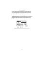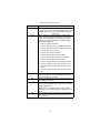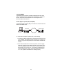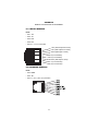
1
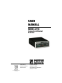
USER
MANUAL
MODEL 2155
CopperLink Ethernet
Extender
Part# 07M2155
Doc# 032111U Rev. A
Revised 2/12/03
An ISO-9001Certified
Company
SALES OFFICE
(301) 975-1000
TECHNICAL SUPPORT
(301) 975-1007
CONTENTS
1.0
1.1
1.2
1.3
Warranty Information .................................................................
Radio and TV Interference............................................................
CE Notice......................................................................................
Service..........................................................................................
3
3
3
4
2.0
2.1
2.2
General Information.................................................................... 5
Features........................................................................................ 5
Description.................................................................................... 5
3.0
3.1
3.2
3.3
3.4
3.5
Installation................................................................................... 7
Connecting the Twisted-Pair Line Interface.................................. 7
Connecting 10Base-T Ethernet Port to PC (DTE) ........................ 8
Connecting 10Base-T Ethernet Port to Hub (DCE) ...................... 8
Connecting Power ........................................................................ 9
Power Input Connector ................................................................. 9
External AC universal power supply............................................. 9
External 48 VDC power supply................................................... 10
4.0
4.1
4.2
Operation...................................................................................
Front Panel LED Status Monitors ...............................................
Test Modes .................................................................................
Remote Digital Loopback (RDL)/V.52 (BER)..............................
A
A.1
A.2
A.3
A.4
A.5
A.6
A.7
A.8
A.9
A.10
A.11
A.12
A.13
Specifications ........................................................................... 14
General Characteristics .............................................................. 14
WAN Characteristics ................................................................... 14
Ethernet ....................................................................................... 14
Distance ...................................................................................... 14
Diagnostics ................................................................................. 14
LED Status Indicators ................................................................. 14
Connectors ................................................................................. 15
Power Supply .............................................................................. 15
Temperature Range .................................................................... 15
Altitude ........................................................................................ 15
Humidity ...................................................................................... 15
Dimensions ................................................................................. 15
Weight ......................................................................................... 15
B
Models 2155 Factory
Replacement Parts and Accessories...................................... 16
11
11
13
13
C
Models 2155 Interface Pin Assignment .................................. 17
C.1 10Base-T Interface ..................................................................... 17
RJ-45 .......................................................................................... 17
C.2 CopperLink Interface .................................................................. 17
RJ-45 .......................................................................................... 17
2
1.0 WARRANTY INFORMATION
Patton Electronics warrants all Model 2155 components to be free from
defects, and will—at our option—repair or replace the product should it
fail within one year from the first date of the shipment.
This warranty is limited to defects in workmanship or materials, and does
not cover customer damage, abuse or unauthorized modification. If this
product fails or does not performs as warranted, your sole recourse shall
be repair or replacement as described above. Under no condition shall
Patton Electronics be liable for any damages incurred by the use of this
product. These damages include, but are not limited to, the following: lost
profits, lost savings and incidental or consequential damages arising
from the use of or inability to use this product. Patton Electronics specifically disclaims all other warranties, expressed or implied, and the
installation or use of this product shall be deemed an acceptance of
these terms by the user.
Note
Conformity documents of all Patton products can be viewed
online at www.patton.com under the appropriate product page.
1.1 RADIO AND TV INTERFERENCE
The Model 2155 generates and uses radio frequency energy, and if not
installed and used properly—that is, in strict accordance with the manufacturer’s instructions—may cause interference to radio and television
reception. The Model 2155 has been tested and found to comply with the
limits for a Class A computing device in accordance with specifications in
Subpart B of Part 15 of FCC rules, which are designed to provide reasonable protection from such interference in a commercial installation.
However, there is no guarantee that interference will not occur in a particular installation. If the Model 2155 does cause interference to radio or
television reception, which can be determined by disconnecting the unit,
the user is encouraged to try to correct the interference by one or more
of the following measures: moving the computing equipment away from
the receiver, re-orienting the receiving antenna and/or plugging the
receiving equipment into a different AC outlet (such that the computing
equipment and receiver are on different branches).
1.2 CE NOTICE
The CE symbol on your Patton Electronics equipment indicates that it is
in compliance with the Electromagnetic Compatibility (EMC) directive
and the Low Voltage Directive (LVD) of the European Union (EU). A Certificate of Compliance is available by contacting Technical Support.
3
1.3 SERVICE
All warranty and non-warranty repairs must be returned freight prepaid
and insured to Patton Electronics. All returns must have a Return Materials Authorization number on the outside of the shipping container. This
number may be obtained from Patton Electronics Technical Services at:
• Tel.: +1 (301) 975-1007
• Email: [email protected]
• URL: http://www.patton.com
Technical support is available from 8 AM to 5 PM EST (8:00 to 17:00
UTC-5), Monday through Friday.
Note
Packages received without an RMA number will not be
accepted.
4
2.0 GENERAL INFORMATION
Thank you purchasing this Patton Electronics product. This product has
been thoroughly inspected and tested and is warranted for one year for
parts and labor. If questions arise while installing or using this product,
contact CopperLink Technical Support at +1 (301) 975-1007.
2.1 FEATURES
• Easy-to-install Ethernet Extenders—no configuration required
• Auto-rate adaption ensures the highest rate possible for each extension distance
• Data rates to 144 kbps
• Half-duplex 10Base-T Ethernet
• Extends network connections up to 5 miles (8 km) over 2-wire 24AWG unconditioned lines (see Appendix A on page 14)
• Transparent operation to higher level protocols such as TCP/IP, DECnet, NETBIOS, IPX, etc.
• LED indicators for Link, Status, No Signal, ER, and Test Mode
• Made in the USA
2.2 DESCRIPTION
The Patton Electronics CopperLink Ethernet Extenders provide highspeed LAN connections between peered Ethernet LANs, remote PC’s, or
any other network enabled 10Base-T device.
Operating in pairs, a Model 2155/L (local) located at one end of the LAN
extension and a Model 2155/R (remote) at the other end, these units can
automatically forward LAN broadcasts, multicasts, and frames across a 2wire voice-grade twisted-pair link. The data is passed transparently
(unmodified) through the Ethernet Extenders. They operate as learning
bridges and automatically add and delete MAC addresses; only passing
packets across the CopperLink line that are meant for the remote peered
LAN.
5
Figure 1. Typical application
The 2155/L and 2155/R work together to create a transparent extension
between two peered Ethernet LANs. Figure 1 shows a typical point-topoint application.
6
3.0 INSTALLATION
Because the CopperLink Ethernet Extender requires no configuration, it can
be installed quickly. Installation consists of the following:
• Connect the line interface between the units (refer to section 3.1,
“Connecting the Twisted-Pair Line Interface” on page 7)
Note
See Figure 2 for the rear-panel connectors locations.
• Connect the Ethernet interface (refer to section 3.2, “Connecting
10Base-T Ethernet Port to PC (DTE)” on page 8 or section section 3.3,
“Connecting 10Base-T Ethernet Port to Hub (DCE)” on page 8).
• Connect the power plug (refer to section 3.4, “Connecting Power” on
page 9).
Interface connector
ON
Made in the USA
|
Power
OFF O
DSL interface
Interface
DSL
Power input
connector
Mo
G.7
Po de
wel 11
r 9
03
/G
4E
Sin
gle
.70
5M1
4T
es
a1dE
e in
tM
Mo
de
od
es
DSFib
L er -
the
US
A
Qu
ad
G.7
03
/G.7
04
InteMo
rfadem
ce
Figure 2. CopperLink Ethernet Extender rear panel
3.1 CONNECTING THE TWISTED-PAIR LINE INTERFACE
The Model 2155 supports communication between two peer Ethernet
LAN sites over a distance greater than 5 miles (8 km) over 24 AWG (0.5
mm) twisted-pair wire.
Follow the steps below to connect the CopperLink interfaces.
Note
Model 2155 units work in pairs. One of the units must be a
Model 2155/L (local) and the other unit must be a Model 2155/R
(remote).
7
1. To function properly, two Ethernet Extenders must be connected
together using twisted-pair, unconditioned, dry, metal wire, between
19 (0.9mm) and 26 AWG (0.4mm). Leased circuits that run through
signal equalization equipment are not acceptable.
2. The Models 2155 are equipped with an RJ-45 interface. The CopperLink interfaces are a two-wire interface. Observe the signal/pin relationships on the CopperLink interface jack.
The RJ-45 connector on the Model 2155’s twisted pair interface is polarity insensitive and is wired for a two-wire interface. The signal/pin relationships are shown in Figure 3 below.
Figure 3. Model 2155 twisted pair line interface
3.2 CONNECTING 10BASE-T ETHERNET PORT TO PC (DTE)
The 10Base-T interface is configured as DTE (Data Terminal Equipment). If the Model 2155 is to to connect to another DTE device such as
a 10Base-T network interface card, construct a 10Base-T crossover
cable and connect the wires as shown in Figure 4.
10Base-T Port
RJ-45 Pin No.
1 (TD+)
2 (TD-)
3 (RD+)
6 (RD-)
10Base-T DTE
RJ-45 Pin No.
1 (TD+)
2 (TD-)
3 (RD+)
6 (RD-)
Figure 4. Connecting 10Base-T Ethernet port to PC
3.3 CONNECTING 10BASE-T ETHERNET PORT TO HUB (DCE)
The 10Base-T interface is configured as DTE (Data Terminal Equipment), just like a 10Base-T network interface card in a PC. Therefore, it
“expects” to connect to a 10Base-T Hub using a straight-through RJ-45
8
cable. Figure 5 shows how to construct a cable to connect the 10Base-T
interface to a 10Base-T Hub.
10Base-T Port
RJ-45 Pin No.
1 (TD+)
2 (TD-)
10Base-T Hub
RJ-45 Pin No.
1 (TD+)
2 (TD-)
3 (RD+)
6 (RD-)
3 (RD+)
6 (RD-)
Figure 5. Connecting the 10Base-T interface to a 10Base-T Hub
3.4 CONNECTING POWER
An external AC or DC power supply is available separately. This connection is made via the barrel jack on the rear panel of the Model 2155. No
configuration is necessary for the power supply (See Appendix B on
page 16 for domestic and international power supply and cord options).
3.5 POWER INPUT CONNECTOR
The 2155 comes with an AC or DC power supply.
• The supplies connection to the CopperLink Ethernet Extender is a
2.5 mm barrel receptacle with the center conductor positive (see
Figure 6).
Figure 6. Power connection barrel receptacle
• CopperLink Ethernet Extender’s rated voltage: 5.0 VDC
• CopperLink Ethernet Extender’s rated current: 1 A DC
External AC universal power supply
• Output from power supply: 5 VDC, 2A
• Input to power supply: universal input 100–240 VAC 50/60 Hz 0.3A
9
An approved external power supply that incorporates a
disconnect device must be used and positioned within
easy reach of the operator’s position.
Caution
Connect the equipment to a 5 VDC source that is electrically isolated from the AC source. The 5 VDC source is to
be reliably connected to earth.
Caution
External 48 VDC power supply
• Input
– Rated voltage: 36–60 VDC
– Rated current: 0.25 A DC at nominal 48 VDC
– 3-pin locking connector, 3.5 mm pitch
– Reverse polarity protection
– Transient over-voltage protection, 100 VDC at 2 ms
• Output
– Rated voltage: 5 VDC ± 5%, 5W
– Rated current; 1 A DC
– 6-inch cable terminated with 2.5 mm barrel plug, center positive
10
4.0 OPERATION
Once the CopperLink Ethernet Extenders are properly installed, they
should operate transparently. No user settings required. This section
describes reading the LED status monitors.
4.1 FRONT PANEL LED STATUS MONITORS
The Model 2155 features six front-panel LEDs that monitor connections on
the DSL and 10Base-T links, signaling, error and test modes. Figure 7
shows the front panel location of each LED. Table 1 describes the LED
functions.
CopperLink™ Ethernet Extender
Model 2155
Link
DSL
DSL
10BT
Status
NS
ER
TM
Status
10BT
TM
NS ER
511E/RDL
Normal
511/RDL
Loopback
switch
Figure 7. CopperLink Ethernet Extender standalone unit front panel
11
Table 1: LED status monitor indications
LED
Description
DSL Link
(Active Green) Solid green (On) indicates that the end to
end DSL Framer Link is up, signifying that the link across
the DSL span is active. The DSL Link LED is Off when the
link is down.
Blinks yellow from one to eleven times to indicate system
status. Each pulse pattern is separated by a 2 second “off”
period. Greater pulse patterns have higher priority (buffer
saturation has greater priority than an empty MAC table).
Valid system statuses are:
Status
• 1 pulse—system status is okay
• 2 pulses—no MAC entries in the MAC Address Table
• 3 pulses—Clear to Send (CTS) or Carrier Detect (DCD)
from base unit are not asserted
•
•
•
•
•
•
•
4 pulses—IM1/I buffer is saturated
5 pulses—WAN receive frame(s) too large
6 pulses—WAN receive frame(s) not octet aligned
7 pulses—WAN receive frame(s) aborted
8 pulses—Detected WAN receive frame(s) with CRC
9 pulses—Detected LAN receive frame(s) too large
10 pulses—Detected LAN receive frame(s) not octet
aligned
• 11 pulses—Detected LAN receive frame(s) with bad
10BT Link
NS
ER
TM
CRC
(Active green) Solid green indicates that the 10Base-T
Ethernet interface has detected a valid SQE heartbeat, signifying a valid 10Base-T connection
(Active red) Solid red indicates that the Digital Signal Processors (DSPs) are not linked
(Active red) Flashing red indicates CRC errors on DSL
(framer) side if DSL Link is active or if bit errors are received
during loop/BER test
ER flashes once, to indicate a CRC error (during normal
operation) or bit errors (during Remote Loopback 511/511E
tests)
(Active yellow) Solid yellow indicates an Active Test Mode.
The unit may be placed in test mode by the local user or by
the remote user.
12
4.2 TEST MODES
The Model 2155 has a built-in proprietary loopback test mode, plus a
built-in V.52 BER test pattern generator, for evaluating the communication link. These tests can be activated from the front panel of the
Model 2155 Ethernet Extenders.
Remote Digital Loopback (RDL)/V.52 (BER)
The Remote Digital Loopback (RDL) test checks the communication link
between two Model 2155s.
Local 2155
Remote 2155
RDL initiated
Figure 8. Remote digital loop
To use the Remote Digital Loopback tests, do the following:
1. Locate the 511/RDL toggle switch on the front panel of the 2155 and
move it DOWN. This initiates the RDL and sends a 511 pattern into
the loop. If any errors are present, the local modem’s red “ER” LED
will blink.
2. If the above test indicates no errors are present, move the toggle
switch UP, activating the 511E/RDL test (with errors present). If the
test is working properly, the local modem’s red “ER” LED will blink
approximately once per second. A successful 511E/RDL test will
confirm that the link is in place, and that the Model 2155’s built-in
“511” error generator and detector are working properly.
13
APPENDIX A
SPECIFICATIONS
A.1 GENERAL CHARACTERISTICS
• Compact low cost plug-and-play router
• 10Base-T Ethernet
• Unlimited host support
• Six front panel LEDs indicate DSL & 10BT Link, No Signal, Error, and
test modes status
• Convenient and standard RJ connectors for Ethernet and line
• External UI AC or 48 VDC power supply options
• Standard 1-year warranty
A.2 WAN CHARACTERISTICS
• 144 kbps
• RJ-45 connector
• Uses two-wire unconditioned twisted-pair
A.3 ETHERNET
• Half-duplex 10Base-T Ethernet
• Standard RJ-45
• IEEE 802.1d transparent learning bridge up to 1,024 addresses
• Addresses deleted after 8 minutes of inactivity
A.4 DISTANCE
2-Wire Distance Table in miles (km)
AWG Wire Gauge (mm)
Data Rate
All rates
19 (.9)
22 (.6)
24 (.5)
6 (.4)
10.8 (17.2)
7.2 (11.5)
5.0 (8.0)
3.4 (5.5)
A.5 DIAGNOSTICS
V.52 compliant bit error rate pattern (511/511E pattern) generator and
detector with error injection mode; Remote Digital Loopback, activated by
front panel switches.
A.6 LED STATUS INDICATORS
DSL, 10Base-T, Status, NS (no signal), ER (error) and TM (test Mode)
14
A.7 CONNECTORS
RJ-45 on line side; shielded RJ-45 on Ethernet port
A.8 POWER SUPPLY
External 100–240 VAC, 50–60 Hz (universal input option), +5 VDC output; 48 VDC (optional), 5 watts, +5 VDC output
A.9 TEMPERATURE RANGE
32–122°F (0–50°C)
A.10 ALTITUDE
0–15,000 feet (0–4,572 meters)
A.11 HUMIDITY
5–95% non-condensing
A.12 DIMENSIONS
4.125W x 1.625H x 6.0D in. (10.5W x 4.1W x 15.2D cm)
A.13 WEIGHT
2.01 lbs. (1.0 kg)
15
APPENDIX B
MODELS 2155 FACTORY
REPLACEMENT PARTS AND ACCESSORIES
Patton Model #
Description
2155 Base Models
2155/L
CopperLink Ethernet Extender; Line: RJ-11 (Local)
2155/R
CopperLink Ethernet Extender; Line: RJ-11 (Remote)
2155-2PK
CopperLink Ethernet Extender Kit: includes one local (L) and
one remote (R) Model 2157
User Manual
07M2155
User Manual
Power Supplies
08055DCUI
100–240VAC (+5V reg. DC/2A) Universal Input Adapter.
Please Call
48 VDC, -5VDC Power Supply
Power Cords*
0805US
American Power Cord
0805EUR
European Power Cord CEE 7
0805UK
United Kingdom Power Cord
0805AUS
Australian Power Cord
0805DEN
Denmark Power Cord
0805FR
France/Belgium Power Cord
0805IN
India Power Cord
0805IS
Israel Power Cord
0805JAP
Japan Power Cord
0805SW
Switzerland Power Cord
*Only required with optional UI power supply (08055DCUI)
16
APPENDIX C
MODELS 2155 INTERFACE PIN ASSIGNMENT
C.1 10BASE-T INTERFACE
RJ-45
• Pin 1: TX+
• Pin 2: TX• Pin 3: RX+
• Pin 6: RX• Pins 4, 5, 7, 8: no connection
1 TX+ (data output from 2155)
2 TX- (data output from 2155)
1
2
3
4
5
6
7
8
3 RX+ (data input to 2155)
4 (no connection)
5 (no connection)
6 RX- (data input to 2155)
7 (no connection)
8 (no connection)
C.2 COPPERLINK INTERFACE
RJ-45
• Pin 4: RING
• Pin 5: TIP
• Pins 1, 2, 3, 6, 7, & 8: no connection
17
Notes
________________________________________________________
________________________________________________________
________________________________________________________
________________________________________________________
________________________________________________________
________________________________________________________
________________________________________________________
________________________________________________________
________________________________________________________
________________________________________________________
________________________________________________________
________________________________________________________
________________________________________________________
________________________________________________________
________________________________________________________
________________________________________________________
________________________________________________________
________________________________________________________
________________________________________________________
________________________________________________________
________________________________________________________
________________________________________________________
________________________________________________________
________________________________________________________
________________________________________________________
18
Notes
________________________________________________________
________________________________________________________
________________________________________________________
________________________________________________________
________________________________________________________
________________________________________________________
________________________________________________________
________________________________________________________
________________________________________________________
________________________________________________________
________________________________________________________
________________________________________________________
________________________________________________________
________________________________________________________
________________________________________________________
________________________________________________________
________________________________________________________
________________________________________________________
________________________________________________________
________________________________________________________
________________________________________________________
________________________________________________________
________________________________________________________
________________________________________________________
________________________________________________________
19
Notes
________________________________________________________
________________________________________________________
________________________________________________________
________________________________________________________
________________________________________________________
________________________________________________________
________________________________________________________
________________________________________________________
________________________________________________________
________________________________________________________
________________________________________________________
________________________________________________________
________________________________________________________
________________________________________________________
________________________________________________________
________________________________________________________
________________________________________________________
________________________________________________________
________________________________________________________
________________________________________________________
________________________________________________________
Copyright © 2002
Patton Electronics Company
All Rights Reserved.
20