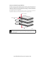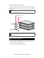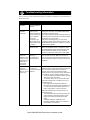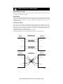
1
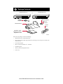
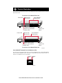
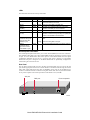
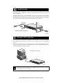
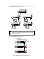
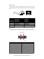
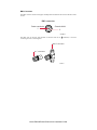
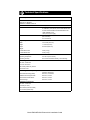
Start Here
Congratulations on your purchase of the NETGEAR™ Model EN516 or Model EN524 Ethernet
hub. These hubs deliver standards-based, plug-and-play networking solutions for small businesses,
home offices, and low-density workgroups of larger companies.
Features
The Model EN516 and Model EN524 hubs have the following features:
•
Sixteen (on the Model EN516 hub) and twenty-four (on the Model EN524 hub) vista
10BASE-T network ports (RJ-45) that provide 10 Mbps networking using simple unshielded
twisted pair (UTP) wiring (The vista network ports provide built-in LED indicators for at-aglance status checks.)
•
AUI or coaxial BNC backbone support for connecting to an existing Ethernet segment or
external transceiver, or for network expansion by connecting multiple hubs together using
twisted pair or coaxial cabling
•
Uplink port for connecting to other hubs using simple straight-through cables
•
Built-in 100 to 240 V AC switching power supply, eliminating the need for bulky wall
transformers
•
Clear front-panel light-emitting diode (LED) indicators, providing the individual ports and
overall hub status
•
Plug-and-play installation with no software to configure
•
Complete hub functions including packet retiming, collision detection, preamble
regeneration, and fragment extension
•
Automatic partitioning and reconnection of a port that has excessive collisions or is jabbering
•
Automatic polarity detection for recognizing and correcting incorrect polarity on the receive
pair
•
Compact design, enabling easy tabletop or rack-mounting installation
•
Limited five-year warranty on the unit and one-year warranty on the power supply
Model EN516/EN524 Ethernet Hub Installation Guide
Package Contents
Model EN516 hub
Model EN524 hub
or
EN516
EN524
MODEL
16PORT
10/100Mbps
Ethernet Hub
1
BNC
Rx
10/100Mbps
9
Ethernet Hub
1
5
Link/Rx Partition
Link/Rx Partition
Normal/Uplink
AUI
Rx
MODEL
24 PORT
8
Link/Rx Partition
Power
Collision Partition Partition
16
Rubber
footpads
Rack mount kit
Power
BNC
Rx
12
Link/Rx Partition
Link/Rx Partition
Normal/Uplink
AUI
Rx
Collision Partition Partition
13
17
24
BNC T-connector
BNC 50 Ω
terminator
Power
cord
Installation guide,
Warranty & Owner
Registration Card
8668FA
Verify that your package contains the following:
•
Model EN516 hub or Model EN524 hub
•
Rack mount kit that includes eight small screws, four large screws, four spacers, and two rack
mount brackets
•
Four rubber footpads
•
BNC T-connector and BNC 50 Ω terminator
•
Installation guide
•
Warranty & Owner Registration Card
•
Power cord
Model EN516/EN524 Ethernet Hub Installation Guide
Product Illustration
The instructions provided in this guide are for installing and using the Model EN516 hub and the
Model EN524 hub.
Front Panel of the Model EN516 hub
Power LED
vista 10BASE-T
network ports
BNC Rx LED
AUI Rx LED
MODEL
16PORT
10/100Mbps
Ethernet Hub
Link/Rx Partition
BNC
Rx
Link/Rx Partition
Normal/Uplink
AUI
Rx
Collision Partition Partition
16
9
Partition LED (for AUI)
Partition LED (for BNC)
Collision LED
Power LED
Normal/
Uplink push
button
vista 10BASE-T
network ports
BNC Rx LED
AUI Rx LED
MODEL
24 PORT
10/100Mbps
Ethernet Hub
1
BNC
Rx
Link/Rx Partition
Link/Rx Partition
Normal/Uplink
AUI
Rx
Collision Partition Partition
EN524
12
5
Link/Rx Partition
Power
EN516
8
1
Power
13
24
17
Partition LED (for AUI)
Partition LED (for BNC)
Collision LED
Normal/
Uplink push
button
Front Panel of the Model EN524 hub
8669FA
Vista 10BASE-T Network Ports with Built-in LEDs
The front panel of the Model EN516 hub has 16 RJ-45 10BASE-T ports, and the Model EN524
hub has 24 RJ-45 10BASE-T ports. Two LEDs—the Link/Rx LED and the Partition LED—are
built into each 10BASE-T port on both models.
Link/Rx Partition
LED
LED
8670EA
Model EN516/EN524 Ethernet Hub Installation Guide
LEDs
The table below describes the activity of the LEDs.
Label
Color
Activity Description
Power
Green
On
Collision
Amber
Blinking Data collision is occurring on the network. Note that
occasional collisions are normal.
BNC Rx
Green
Blinking There is incoming data on the BNC port.
Partition
(for BNC)
Amber
On
AUI Rx
Green
Blinking There is incoming data on the AUI port.
Partition
(for AUI)
Amber
On
The AUI port is partitioned because of excessive
collisions or because the signal quality error (SQE) test
function is not disabled on the transceiver.
Link/Rx
(located on the top left
corner of each vista
10BASE-T port)
Green
On
The link between this port and the connected device is
good.
Partition
(located on the top
right corner of each
vista 10BASE-T port)
Amber
Power is supplied to the hub.
The BNC port is partitioned because of excessive
collisions or the BNC port is not connected.
Blinking There is incoming data on the port.
On
The port is partitioned because of excessive collisions.
Normal/Uplink Push Button
The Normal/Uplink push button allows you to select Normal (MDI-X) for direct PC connection.
The push button also allows you to select Uplink (MDI) wiring for connection to a hub or a switch
for port 16 on the Model EN516 hub and for port 24 on the Model EN524 hub. This uplink
configuration eliminates the need to use a crossover cable. Ports 1 through 15 on the Model
EN516 hub and ports 1 through 23 on the Model EN524 hub are permanently configured for
normal wiring for connection to a PC.
Rear Panel
The rear panel of each hub has two ports: the AUI port and the BNC port. You can use the AUI
port with the appropriate transceiver to connect the hub to a backbone network using thin coaxial
cable, thick coaxial cable, fiber optic cable, or 10BASE-T wiring. You can use the BNC port to
connect to a backbone network or other PCs using thin coaxial cable. The rear panel also includes
an AC power receptacle. The hub accepts between 100 and 240 V AC, 50/60 Hz.
AUI port
BNC port
Power receptacle
BNC
AUI
100-240 VAC 50-60 Hz 0.2A
8143FA
Model EN516/EN524 Ethernet Hub Installation Guide
Installation Procedures
Prepare the Site
Before you begin installing your hub, prepare the installation site. Make sure your operating
environment meets the operating environment requirements of the equipment.
Characteristic
Requirement
Temperature
Ambient temperature between 0° and 40° C (32° and 104° F).
No nearby heat sources such as direct sunlight, warm air exhausts, or
heaters.
Operating humidity
Maximum relative humidity of 90%, noncondensing.
Ventilation
Minimum 2 inches (5.08 cm) on all sides for cooling.
Adequate airflow in room or wiring closet.
Operating conditions
At least 6 feet (1.83 m) to nearest source of electromagnetic noise (such
as photocopy machine or arc welder).
Service access
Minimum 12 inches (19.68 cm) front and back for service access and
maintenance.
Front and back clearance for cables and wiring hardware such as
punchdown blocks.
Power
Adequate power source within 6 feet (1.83 m).
Tabletop requirements Flat area approximately 13 inches (33.0 cm) by 8 inches (20.3 cm).
Rack requirements
Standard 19-inch (48.26 cm) EIA equipment rack, with supplied mounting
bracket hardware; 1.0 EIA rack-mount spaces needed for each
NETGEAR hub.
Wiring hardware
Wiring hardware, such as punchdown blocks or patch panels, should be
complete before installing the hub.
Model EN516/EN524 Ethernet Hub Installation Guide
2
Install the Hub
To install your hub on a flat surface, you do not need any special tools. Install the rubber footpads
that are included in the package. Be sure the hub is positioned with at least 2 inches of space on all
sides for ventilation.
To install the hub in a rack, you need two Phillips screwdrivers: one size for the screws that attach
the brackets to the hub and another size for the screws that attach the brackets to the mounting
rack. Be sure to choose a location that is near the devices to be connected, is close to an electrical
outlet, and provides at least 2 inches of space all around the hub for ventilation.
1
Power
Data Collisi
Link
on
RX
5
13
Link
RX
17
12
Link
RX
Norma
l/Uplin
k
24
(Model EN524 hub shown)
8666FA
Connect a PC to the Hub
You can connect PCs, Apple Macintosh computers, UNIX workstations, or any device equipped
with a 10BASE-T Ethernet interface to the RJ-45 ports on your hub by using twisted pair Ethernet
cables.
To connect any of the RJ-45 ports on your hub to a PC, use a regular straight-through UTP cable.
If you are connecting using port 16 on the Model EN516 hub or port 24 on the Model EN524 hub,
set the Normal/Uplink push button to Normal.
(Model EN524 hub shown)
1
Data Collisio
n Power
Power
Data Collisio
Link
n
RX
5
13
Link
RX
17
Link
12
RX
Normal
/Uplink
24
8667FA
Note: Ethernet specifications limit the cable length between your PC or server and the
hub to 328 feet (100 meters) in length.
Model EN516/EN524 Ethernet Hub Installation Guide
Connect the Hub to a Network
Cascading refers to connecting hubs together to increase the number of ports or the number of
users supported on the network. The 10BASE-T, BNC, or AUI ports can be used to cascade hubs
together.
Connect to a Network Using the 10BASE-T Ports
The twisted pair cable extended from a 10BASE-T port (or UTP port) is called a twisted pair
segment and can be up to 100 meters (m) in length. The 10BASE-T ports, with the exception of
port 16 on the Model EN516 hub and port 24 on the Model EN524 hub, are MDI-X (or Normal)
ports. Use the following table as a guide for selecting the appropriate network cable.
Connecting Port
on the Hub
Connecting Device
Cable Used
Model EN516 hub:
Ports 1–15
PC, server, or router
Straight-through cable
Ports 1–15
Hub or switch
Crossover cable
Model EN524 hub:
Ports 1–23
PC, server, or router
Straight-through cable
Ports 1–23
Hub or switch
Crossover cable
Set the Normal/Uplink Push Button
If you are connecting to port 16 on the Model EN516 hub or to port 24 on the Model EN524 hub,
use the following table. Determine the type of cable to use and how to set the Normal/Uplink push
button for either port 16 or port 24.
Connecting Port
Connecting Device
Cable Used
Port 16 or port 24 set to Normal
PC, server, or router
Straight-through cable
Port 16 or port 24 set to Uplink
Hub or switch
Straight-through cable
Model EN516/EN524 Ethernet Hub Installation Guide
You can cascade hubs together through any of the ports. The following illustration shows
cascading hubs together in a hierarchical star through the 10BASE-T ports and indicates the
setting of the Normal/Uplink push button on each hub.
Normal
Model EN524 hub
1
Uplink
Uplink
Model EN516 hub
2
Model EN524 hub
MODEL
16PORT
10/100Mbps
Ethernet Hub
Link/Rx Partition
BNC
Rx
3
EN516
8
1
Power
Link/Rx Partition
Normal/Uplink
AUI
Rx
Collision Partition Partition
16
9
Uplink
Uplink
Model EN524 hub
Model EN516 hub
4
5
MODEL
16PORT
10/100Mbps
Ethernet Hub
Link/Rx Partition
BNC
Rx
EN516
8
1
Power
Link/Rx Partition
Normal/Uplink
AUI
Rx
Collision Partition Partition
16
9
A
B
8664FA
Note: Ethernet specifications limit the number of hubs with twisted pair links in any
communication path to five, as shown in the example. When PC “A” communicates
with PC “B,” the communication path goes from hub 4 to hub 2, to hub 1, to hub 3,
and then to hub 5 (or five paths).
The following illustration shows cascading hubs together daisy-chain style and indicates the
setting of the Normal/Uplink push button on each hub.
Model EN516 hub
EN516
MODEL
16PORT
10/100Mbps
Ethernet Hub
1
8
Link/Rx Partition
Power
BNC
Rx
Link/Rx Partition
Normal/Uplink
AUI
Rx
Collision Partition Partition
9
16
Normal
Model EN524 hub
Uplink
Model EN524 hub
Uplink
8665FA
Model EN516/EN524 Ethernet Hub Installation Guide
Connect to a Network Using the BNC Port
The BNC port on the rear panel of the hub is used for connecting to a thin coaxial segment. You
can connect other Model EN516 or Model EN524 hubs, servers, workstations, or other devices to
the BNC port. A BNC-T connector is inserted in the port, and the 50 Ω terminator terminates the
connection at each end device. By using the BNC port for cascading, you treat each connected hub
as just another node on the coaxial segment.
The separation marks in the coaxial cable between the hubs in this illustration represent the
incorporation of other devices and show that interconnection is not limited to hubs.
BNC T- connector
BNC 50
terminator
BNC 50
terminator
8074FA
Note: Ethernet specifications limit a BNC segment to 30 BNC connections, specify a
minimum of 1.64 feet (0.5 m) between any two stations, and limit segments to 607 feet
(185 m) in length.
Model EN516/EN524 Ethernet Hub Installation Guide
Connect to a Network Using the AUI Port
The AUI port on the rear panel of the hub is normally used for connecting a thick coaxial segment.
With the right type of transceiver, you can use the AUI port to connect to most types of network
media, including 10BASE-T twisted pair cable or thin coaxial, thick coaxial, and 10BASE-FL
fiber optic cables.
Note: All transceivers connected to the AUI port must have the signal quality error
(SQE) test function disabled. Refer to your transceiver documentation for information
about disabling the SQE test function.
Cable terminator device
AUI cable
Thick
coaxial
cable
10BASE-5
transceiver
8075FA
Note: Ethernet specifications limit segments to 100 stations and 1,640 feet (500 m) in
length, and they specify that the AUI cable between the hub and the transceiver is
limited to 164 feet (50 m).
Verify the Installation
To complete the installation, connect the power cord first to the power receptacle on the hub rear
panel and then to the power outlet on the wall. When power has been applied to the hub:
•
The green Power LED on the front panel is on.
•
The green Link/Rx LED on each connected port is on.
If there are any problems, refer to “Troubleshooting Information.”
Model EN516/EN524 Ethernet Hub Installation Guide
Troubleshooting Information
Refer to this table and the information that follows the table to troubleshoot your Model EN516 or
Model EN524 hub.
Symptom
Cause
Solution
Amber Collision
LED blinks.
Data collision is
normal on Ethernet
networks.
No action is required.
Amber Collision
LED blinks
excessively.
There is data
collision on the
network because the
network is extremely
busy or defective
devices are
connected on the
network that cannot
detect network traffic
or collision.
Make sure connected devices are operating in halfduplex mode. The hub is not compatible with devices
that operate in full-duplex mode.
If you suspect that there might be a defective device on
the network, disconnect devices one at a time to isolate
the defective unit on the network.
If the network is extremely busy, you may have to
segment the network with an Ethernet switch such as a
NETGEAR Ethernet switch or to upgrade your network
to Fast Ethernet operation.
Wrong or miswired
cables are used.
Make sure the correct UTP cables are used. See the
table in the installation section of this guide for cable
use and Normal/Uplink push button information. Note
that home telephone cables can cause a collision
condition and cannot be used in place of UTP cables.
Green Link/Rx
LED on the
10BASE-T port is
off when a cable
is attached or not
blinking when
there is data
transmission.
The port is not
detecting a
successful link or
data transmission.
Check for a bad cable, cable pairs that are not correctly
wired, or loose connectors. Make sure that there is
power to both the hub and the Ethernet transceiver on
the connected device. Make sure the port has not been
partitioned.
Amber Partition
LED on the
10BASE-T port,
BNC port, or AUI
port turns on.
The connected port
is partitioned
because of excessive
collisions.
The 10BASE-T port, BNC port, or AUI port is
partitioned after 32 consecutive collisions are detected.
When the first good packet without a collision is
received, the port is reconnected and the amber
Partition LED turns off. Check and correct causes listed
in this table for excessive collisions. Make sure that:
• The correct cable is used and the cable is not faulty.
• There are no faulty connectors.
• The network card in your PC is set to half-duplex.
If the amber Partition LED on the BNC port turns on,
also make sure that:
• Each segment is terminated with a BNC 50 Ω
terminator at both ends. Note that if the BNC port is
not in use and the amber Partition LED turns on
(which could happen), no action is required.
If the amber Partition LED on the AUI port turns on,
also make sure that:
• The coaxial transceiver is functioning properly, the
coaxial segment is terminated properly, and the
segment is not disconnected along the cable
length.
• The signal quality error (SQE) test on the
transceiver is disabled. Refer to your transceiver
documentation for instructions.
Model EN516/EN524 Ethernet Hub Installation Guide
Cable Connector Information
Network Interface Cards
Make sure the network interface cards installed in the workstations are in working condition and
the software driver has been installed.
Hub Integrity
If required, verify the integrity of the hub by resetting it. Turn power to the switch off and then
back on. If the problem continues and you have completed all the preceding diagnoses, contact
NETGEAR Customer Support. For the phone number of the representative in your area, see
“Customer Support.”
Twisted Pair Cables
For two devices to communicate, the transmitter of each device must be connected to the receiver
of the other device. The crossover function is usually implemented in- ternally as part of the
circuitry in the device. Most ports on switches and repeaters have media-dependent inter- faces
with crossover ports. These ports are referred to as MDI-X or Normal ports. Computer and
workstation adapter cards are usually mediadependent interface ports referred to as MDI or Uplink ports.
The figures illustrate the use of straight-through and crossover twisted pair cables.
Straight-through
twisted pair cable
Uplink or
MDI port
Normal or
MDI-X port
1
1
2
2
3
3
6
6
Tx
Rx
Rx
Tx
Normal or
MDI-X port
Crossover
twisted pair cable
Normal or
MDI-X port
1
1
2
2
3
3
6
6
Rx
Rx
Tx
Tx
8146EB
Model EN516/EN524 Ethernet Hub Installation Guide
RJ-45 Connector
The RJ-45 connector (shown in the illustration with an RJ-45 plug) is used to connect
workstations, hubs, and switches through unshielded twisted pair cable. The RJ-45 connector
accepts four-pair Category 3 or Category 5 UTP cable. Only two pairs are used for 10BASE-T
wiring.
12345678
8
1
711EA
Normal Assignment:
Ports 1–15 on the
Model EN516 hub
RJ-45 Connector Ports 1–23 on the
Pin Assignment Model EN524 hub
Uplink Assignment:
Port 16 on the
Model EN516 hub
Port 24 on the
Model EN524 hub
1
Input Receive Data +
Output Transmit Data +
2
Input Receive Data -
Output Transmit Data -
3
Output Transmit Data +
Input Receive Data +
6
Output Transmit Data -
Input Receive Data -
4, 5, 7, 8
Not used
Not used
AUI Connector
The AUI connector for the hub connects the hub through an external transceiver to other devices.
An inter-repeater fiber link using a 10BASE-F transceiver is an example of such an application.
AUI connector
1
8
15
9
8148EA
AUI Connector Pin Assignment
Signal
1, 4, 11, 14, 15
Ground
2
CI-A
3
DO-A
5
DI-A
6
+ 12 V DC return
7, 8
Not used
9
CI-B
10
DO-B
12
DI-B
13
+ 12 V DC (500 mA maximum)
Model EN516/EN524 Ethernet Hub Installation Guide
BNC Connector
The BNC connector for the hub supports 10 Mbps data transmission and connects the hub to other
devices.
BNC connector
Center conductor
1
Ground shield
2
8149EA
The BNC port on the hub, with the BNC T-connector and the 50 Ω terminator, is used for
connecting to a thin coaxial segment.
BNC T-connector
50 Ω terminator
50
OHM
8150FA
Model EN516/EN524 Ethernet Hub Installation Guide
Technical Specifications
General Specifications
Network Protocol and Standards Compatibility
IEEE 802.3i, 10BASE-T,
10BASE-2, 10BASE-5 Ethernet
Data Rate
10 Mbps, Manchester encoded
Interface
16 10BASE-T ports (RJ-45) on the Model EN516 hub
24 10BASE-T ports (RJ-45) on the Model EN524 hub
On both the Model EN516 and Model EN524 hubs:
1 BNC 10BASE-2 port
1 AUI port (15-pin D-type)
Power
100–240 V, 50/60 Hz,
(auto selection)
0.15 A maximum
Physical Specifications
Width:
13.0 inches (330 mm)
Height:
1.7 inches (43 mm)
Depth:
8.0 inches (203 mm)
Weight:
Model EN516 hub
4.8 lb (2.2 kg)
Model EN524 hub
5.0 lb (2.3 kg)
Environmental Specifications
Operating temperature:
0° to 40° C (32° to 104° F)
Operating humidity:
90% maximum relative humidity, noncondensing
Electromagnetic Emissions
CE mark, commercial
FCC Part 15 Class A
EN 55 022 (CISPR 22), Class A
VCCI Class 1 ITE
Electromagnetic Susceptibility
CE mark, commercial
Electrostatic discharge (ESD):
IEC 801-2, Level 2/3/4
Radiated electromagnetic field:
IEC 801-3, Level 2
Electrical fast transient/burst:
IEC 801-4, Level 2
Electrical surge:
IEC 801-5, Level 2
Safety Agency Approvals
CE mark, commercial
UL listed (UL 1950)
CSA certified (CSA 22.2 #950)
TUV licensed (EN 60 950)
Model EN516/EN524 Ethernet Hub Installation Guide
© 1998 by NETGEAR, Inc. All rights reserved.
Trademarks
Bay Networks is a registered trademark of Bay Networks, Inc. NETGEAR is a trademark of Bay Networks, Inc.
All other trademarks and registered trademarks are the property of their respective owners.
Statement of Conditions
In the interest of improving internal design, operational function, and/or reliability, NETGEAR reserves the right to make changes to the products
described in this document without notice.
NETGEAR does not assume any liability that may occur due to the use or application of the product(s) or circuit layout(s) described herein.
Certificate of the Manufacturer/Importer
It is hereby certified that the Model EN516 and Model EN524 Ethernet hubs have been suppressed in accordance with the conditions set out in the
BMPT-AmtsblVfg 243/1991 and Vfg 46/1992. The operation of some equipment (for example, test transmitters) in accordance with the regulations
may, however, be subject to certain restrictions. Please refer to the notes in the operating instructions.
Federal Office for Telecommunications Approvals has been notified of the placing of this equipment on the market and has been granted the right
to test the series for compliance with the regulations.
Voluntary Control Council for Interference (VCCI) Statement
This equipment is in the first category (information equipment to be used in commercial and/or industrial areas) and conforms to the standards set
by the Voluntary Control Council for Interference by Data Processing Equipment and Electronic Office Machines that are aimed at preventing radio
interference in commercial and/or industrial areas.
Consequently, when this equipment is used in a residential area or in an adjacent area thereto, radio interference may be caused to equipment such
as radios and TV receivers.
Federal Communications Commission (FCC) Compliance Notice: Radio Frequency Notice
Note: This equipment has been tested and found to comply with the limits for a Class A digital device, pursuant to Part 15 of the FCC rules. These
limits are designed to provide reasonable protection against harmful interference when the equipment is operated in a commercial environment.
This equipment generates, uses, and can radiate radio frequency energy. If it is not installed and used in accordance with the instruction manual, it
may cause harmful interference to radio communications. Operation of this equipment in a residential area is likely to cause harmful interference,
in which case users will be required to take whatever measures may be necessary to correct the interference at their own expense.
EN 55 022 Statement
This is to certify that the Model EN516 and Model EN524 Ethernet hubs are shielded against the generation of radio interference in accordance
with the application of Council Directive 89/336/EEC, Article 4a. Conformity is declared by the application of EN 55 022 Class A (CISPR 22).
This is a Class A product. In a domestic environment, this product may cause radio interference, in which case, the user may
be required to take appropriate measures.
Canadian Department of Communications Radio Interference Regulations
This digital apparatus (Model EN516 and Model EN524 Ethernet hubs) do not exceed the Class A limits for radio-noise emissions from digital
apparatus as set out in the Radio Interference Regulations of the Canadian Department of Communications.
Règlement sur le brouillage radioélectrique du ministère des Communications
Cet appareil numérique (Model EN516 et Model EN524 Ethernet hubs) respecte les limites de bruits radioélectriques visant les appareils
numériques de classe A prescrites dans le Règlement sur le brouillage radioélectrique du ministère des Communications du Canada.
Model EN516/EN524 Ethernet Hub Installation Guide
NETGEAR, Inc.
A Bay Networks Company
4401 Great America Parkway
Santa Clara, CA 95054 USA
Phone: 888-NETGEAR
Customer Support
Phone
Australia: 1800-142-046
France: 0800-90-2078
Germany: 0130-817305
Japan: 0120-66-5402
Korea: 00308-11-0319
New Zealand: 0800-444-626
Sweden: 020-790086
United Kingdom: (44) 171-571-5120
U.S./Canada: 800-211-2069
Internet/World Wide Web
The NETGEAR Web page is at http://NETGEAR.baynetworks.com.
Defective or damaged merchandise can be returned to your point-of-sale
representative.
*M-EN500NA-0*