1
HOME APPLIANCES
Part No. 9751596
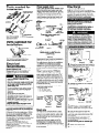
ALL RANGES CAN TIP
l INJURY TO PERSONS
COULD RESULT
l
l
INSTALL ANTI-TIP
DEVICE PACKED
WITH RANGE
SEE INSTALLATION
INSTRUCTIONS
IMPORTANT:
Read and save
these instructions.
IMPORTANT:
Installer: Leave Installation Instructions
with the
homeowner.
Homeowner: Keep Installation Instructions and anti-tip
bracket template for future reference.
Save Installation Instructions for local electrical
inspector’s use.
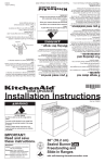
30” (76.2 cm)
Electric Slide-in
with self-cleaning
thermal/convection
oven
Range
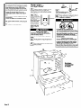
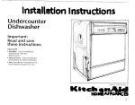
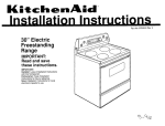
Cabinet opening dimensions
Before you start...
25” (63.5 cm) countertop
Read electrical and carpentry instructions.
Proper installation is your responsibility. A
upper cabinet
For minimum
clearance to the top
of the cooktop, see
depth
18” (45.7 cm)
4” (10 2 cm) min
clearance to side will A
or other combustible
material
of range.
Do Not pinch the
ower supply cord
Eetween the range
and the wall.
\
wall receptacle 8” (20.3 cm) to
22” (55.9 cm) from
either cabinet,
7” (17.8 cm) max.
from floor.
I
Important: Observe
all governing codes
and ordinances.
Grounded electrical
outlet is required. See
“Electrical
Panel B.
requirements,”
I
I
-H 3
1
718” (2:2%)
e H min. required
\ between
cutout and
cabinet door
or hinge.
\
1
***
36” (91.4 cm)
countertop
height
Cabinet opening
dimensions that are
I
shown must be used.
Y
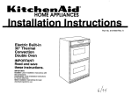
Countertop
Do Not seal range
to side cabinets.
w
preparation
Note: 24” (61 cm) min. when bottom of
wood or metal cabinet is protected by
not less than l/4” (0.64 cm) flame
retardant millboard covered with not
less than No. 28 MSG sheet steel, 0.015”
(0.4 mm) stainless steel, 0.024” (0.6 mm)
aluminum or 0.020” (0.5 mm) copper.
30” (76.2 cm) min. clearance between
the top of the cooking platform and
the bottom of an unprotected
wood or
metal cabinet.
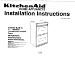
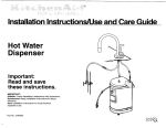
The cooktop sides of the slide-in range fit over
the cutout edge of your countertop.
If countertop opening width is greater than
30-318” (77.2 cm), adjust the l/4” (0.64 cm)
If you have a square finish (flat) countertop
and the opening width is 30-3/8” (77.2 cm), no
dimension.
countertop
preparation
Countertop must be level. Place level on
countertop, first side to side; then front to back. If
countertop is not level, range will not be level.
Oven must be level for satisfactory baking
conditions.
is required.
Formed front-edged countertops:
Must have
molded edge shaved flat l/4” (0.64 cm) from
each front corner of opening.
Tile countertops may need trim cut back
l/4” (0.64 cm) from each front corner and/or
rounded edge flattened.
I
countertoo
I
Formed or tiled countertop
trimmed l/4” (0.64 cm)
back at front corners of
countertop
opening.
Anti-tip
bracket:
MUST be installed.To install
the anti-tip bracket shipped
with the range, see Panels D
and E and the anti-tip
bracket template.
-4
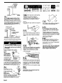
Panel A
Personal Injury Hazard
To eliminate the risk of burns or fire, avoid
installing cabinet storage above the cooking
surface. If cabinets are already installed,
reduce the hazard of reaching over a heated
cooking surface by installing a range hood.
The range hood should extend a minimum of
5 inches out from the bottom front of the
cabinets.
Reaching over a heated cooking surface
could result in a serious burn or other
personal injury.
Electrical Shock Hazard
lt is the customer’s responsibility:
.To contact a qualified electrical installer.
*To assure that the electrical installation is
adequate and in conformance with National
Electrical Code, ANWNFPA
70 - latest edition’, or CSA Standard C22.1,
Canadian Electrical Code, Part 1 -latest
edition”, and all local codes and ordinances.
Failure to do so could result in fire, electrical
shock or other personal injury.
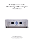
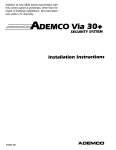
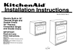
Mobile home installation
Product dimensions
Yl7
qualified technician must install this range. Make
sure you have everything necessary for correct
installation. It is the customer’s responsibility to
make sure that the countertop has been properly
prepared and that the installation clearances
specified on the serial/rating plate are met. The
serial/rating plate is located on the frame behind
the drawer.
Check location where range will be installed.
The range should be located for convenient use
in the kitchen. Recessed installations must
provide complete enclosure of the sides and rear
of range.
ALL OPENINGS IN THE WALL OR FLOOR
WHERE RANGE IS TO BE INSTALLED MUST
BE SEALED.
Cutout shown is for a 25inch (63.5 cm)
countertop with a 24-inch (61 cm) base cabinet
and no backsplash. If countertop has a
backsplash, see “Countertop preparation.”
Cabinet construction: This appliance is
designed for use in a base cabinet with a depth
of 24 inches (61 cm). The maximum depth for
overhead cabinets is 13” inches
(33 cm). For the minimum vertical clearance
between the cooking surface and the overhead
cabinets, see Note.*** Overhead cabinets
installed at either side of the appliance must be
a minimum of 18 inches (45.7 cm) above the
cooking surface. The minimum horizontal
distance between the overhead cabinets is 30
inches (76.2 cm).
30” 176.2 cm)
range width ’
When installed in a 24” (61 cm)
base cabinet with 25” (63.5 cm)
countertop
- front of oven door
protrudes l-7/8” (4.8 cm) beyond
24” (61 cm) base cabinet.
The installation of this range must conform to the
Manufactured Home Construction and Safety
Standards, Tile 24 CFR, Part 3280 (formerly the
Federal Standard for Mobile Home Construction
and Safety, Title 24, HUD, Part 280); or when such
standard is not applicable, the Standard for
Manufactured Homes Installations (Manufactured
Home Sites, Communities and Setups), ANSI
A2251/NFPA 501A, or with local codes’. In
Canada, the installation of this range must conform
with the current standards CANKSA - 2240 latest edition** or with local codes.
In Canada, the installation of this range must
conform with the current standards CAN/CSA-Z240
- latest edition***, or with local codes.
When this range is installed in a mobile home, it
must be secured to the floor during transit. Any
method of securing the range is adequate as long
as it conforms to the standards listed above.
Four-wire power supply cable must be used in a
mobile home installation. The appliance wiring will
need to be revised. See four-wire electrical
connection, Panels C and D.
Note: The metal chassis of the range MUST be
earth- grounded in order for the control panel to
work. If the metal chassis of the range is not earthgrounded, NO keypads will operate. Check with a
qualified electrician if you are in doubt as to whether
the metal chassis of range is earth-grounded.
Copies of the standards listed may be obtained from:
* National Fire Protection Association
Batterymarch
park
Guincy, Massachusetts
02269
** Canadian Standard Association
178 Rexdale Boulevard
Rexdale (Toronto), Ontario M9W 1 R3
Tools needed for
installation:
flat-blade screwdriver
or-5116” (0.8 cm) nut
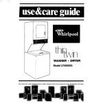
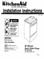
Power supply cord
Use a new 40-amp power supply cord.
Local codes may permit the use of a U.L.-listed,
250~volt, 40-ampere range power supply cord
(pigtail). Power supply cord should be Type SRD
or SRDT and be at least four feet long. The wires
that connect to the range must end with ring
terminals. A 3/4” (1.9 cm), U.L.-listed strain relief
must be installed where the power supply cord
connects to the range. (See Figures 1 and 2.)
ring
terminals
This blade connected
to this conduc
strain relief
Three-wire power supply
NEMA lo-50P
Figure 1
hand or electric drill wood
floor: l/8” (0.3 cm) drill bit
concrete/ceramic
floor:
3/16” (0.48 cm) carbidetipped masonry drill bit
Parts supplied
installation:
grounding
NOTE: The metal chassis of the range MUST be
earth-grounded in order for the control panel to work.
If the metal chassis of the range is not earthgrounded, NO keypads will operate. Check with a
qualified electrician if you are in doubt as to whether
the metal chassis of range is earth-grounded.
Where local codes permit connecting the
frame-grounding conductor to the neutral
(white) junction box wire:
This appliance is manufactured with the
neutral terminal connected to the cabinet. If
local codes Do Not permit connecting
cabinet-grounding conductor to neutral wire,
use “Four-wire connection” instructions.
(white or center)
cord
314” 1.9 cm)
U.L.- I isted
strain relief \.
for
Electrical
connections
NEUTRAL
(white)
Electrical Shock/Fire Hazard
Check that wiring you are using matches
colors shown in illustrations and specified
in instruction steps. If wiring does Not
match, it is your responsibility to have a
qualified electrician install correct wiring.
Failure to follow these instructions could
result in fire, electrical shock or death.
prong
Four-wire power supply cord
(Mobile home or other four-wire
installations)
NEMA lo-5OP
Figure 2
(Bracket must be securely mounted to subfloor. Thickness of flooring may require longer
screws to anchor the bracket to sub-floor.)
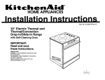
Electrical
requirements
Save Installation Instructions for the local
electrical inspector’s use.
Power supply cord is not provided and is
available through your local electrical
supply houses.
Electrical Shock Hazard
l Electrical
ground is required on this
appliance.
. Use only a new power supply cord kit ratec
at 250 volts, 40 amperes and investigated
for use with ranges. Do Not reuse an old
power supply cord.
l Do Not modify the power supply
cord plug
If it does not fit the outlet, have a proper
outlet installed by a qualified electrician.
l Do Not use an extension
cord with this
appliance.
l Do Not ground
to a gas pipe.
l Do Not have a fuse in the neutral
or
grounding circuit. A fuse in the neutral or
grounding circuit could result in an
electrical shock.
l Check with a qualified
electrician if you arc
in doubt as to whether the appliance is
properly grounded.
Failure to follow these instructions could
result in serious injury or death.
The power supply cord must have three No.-10
copper wires to match a three-wire receptacle of
NEMA Type 1 O-50R. (See Figure 3.)
For mobile home or other four-wire installations:
This appliance is manufactured with ground
connected to cabinet. The ground must be
revised so the green grounding wire of the fourwire power cord is connected to the cabinet. See
four-wire electrical connection section, Panels C
and D.
When a four-wire receptacle of NEMA Type
14-50R is used (See Figure 4.), a matching
U.L.-listed, four-wire, 250~volt, 40-ampere, range
power supply cord (pigtail) must be used. This
cord contains four copper conductors with ring
terminals on the appliance end, terminating in a
NEMA Type 14-50P plug on the supply end. The
fourth (grounding) conductor must be identified
by a green or green/yellow cover and the neutral
conductor by a white cover. Cord should be Type
SRD or SRDT with a U.L.-listed strain relief and
be at least four feet long.
The MINIMUM conductor sizes for the copper
4-wire power supply cord are:
40-ampere circuit
2, No.-8 conductors
1, No.-1 0 white neutral
1, No.-8 green grounding
For use where
local codes
ermit use of
Plexible power
supply cord.
P
3
2.
Remove the terminal block cover located on
back of range. Remove the 3/8” (0.95 cm) brass
terminal nuts attached to the knockout.
3.
Remove the knockout for the 40-ampere
power supply cord.
silver-colored
’’
\\\\\\
1
1
UG
ny$l
three-wire wall
receptacle
(16SOR)
four-wire wall
receptacle
(14~SOR)
Figure 3
Figure 4
If codes permit and a separate grounding wire
is used, it is recommended that a qualified
electrician determine that the grounding path
is adequate.
Direct wire
A three-wire or four-wire, single-phase, 120/240volt, 60-Hz, AC-only, electrical supply (or threewire or four-wire 120/208-volt if specified on the
serial/rating plate) is required on a separate
40-ampere circuit, fused on both sides of the line. A
time-delay fuse or circuit breaker is recommended.
THE RANGE MUST BE CONNECTED WITH
COPPER WIRE ONLY.
Wire sizes (COPPER WIRE ONLY) and
connections must conform with the rating of the
appliance (40 amperes).
A wiring diagram is located on back of range.
The range can be connected directly to fused
disconnect or circuit breaker box through flexible,
armored or non-metallic sheathed, copper cable
(with grounding wire). Do Not use two-wire with
bare grounding wire. All current-carrying wires
must be insulated.
A U.L.-listed conduit connector must be provided
at each end of the power supply cord (at the
appliance and at the junction box). USE ONLY
lo-GAUGE SOLID COPPER WIRE. DO NOT
USE ALUMINUM. Allow two or three feet of slack
in the line so the range can be moved if servicing
is ever necessary.
Panel B
cover
Figure 5
n
Figure 7
U.L.-listed
’
strain relief
i
Attach a 314” (1.9 cm) U.L.-listed strain
on strain relief) to the
rain relief firmly to cabinet.
Place power supply cord through strain relief.
Using the 3/8” (0.95 cm) brass nuts,
ch the neutral (white) wire of power supply
to the center, silver-colored screw of the
her two wires to the outer
rews. (See Figure 7.)
e factory-installed nuts on
g nuts are installed tight.
6.
Tighten strain relief screws
.-:-..:
:..
:::.::.:::.
Iv
..-.-.-.-. . Reattach terminal block cover.
c
1
0
Mobile
1. Turn
home
or
l
-
other
0
four-wire
power supply off.
Electrical Shock/Fire Hazard
Check that wiring you are using matches
colors shown in illustrations and specified
in instruction steps. If wiring does Not
match, it is your responsibility to have a
qualified electrician install the correct
wiring.
Failure to follow these instructions could
result in fire, electrical shock or death.
Electrical Shock Hazard
Do Not use two wire with a bare
grounding wire. All current-carrying wires
must be insulated.
Failure to follow these instructions could
result in fire, electrical shock or death.
..,,,..-..:
:;xr::;ig
:;j:$~$;
.:::‘“:
..-.-.-.-.. Turn power supply off.
..::::-..
..-...-...
...:..::..
.......-..
....
.:;:;:::;:::i
..._.......
_.....
._...........
.i:;:;:;:;:;:
...
I’
installations:
7-
.:;:/:/:j:j:j
.....
:.....,.,,
hook
Figure 17
’ ’
I
jjjj;j;j;jjj
::::::::::::
Direct wire preparation
......,.
;<;;j;g
:,:,:,:.:.:.
2. Strip outer covering back 3 inches (7.6 cm)
::::::::::::
Figure
$33
from
end
exposing
the
wires.
(See
Figure
17.)
(2.5 cm) from
the end of each wire. Form the bare wire into a
“U” .&aped hook. (See Figure 18.)
Strip
the
insulation
back
1
inch
::.:-:...-.
:>>::: . Turn power supply off.
Figure 9
Direct wire preparation
2. Strip outer covering back 3 inches (7.6 cm)
from end exposing the wires. (See Figure 8.)
Strip the insulation back 1 inch (2.5 cm) from
the end of each wire. Form the bare wire into a
“U” shaped hook. (See Figure 9.)
. terminal
v
J
g/g
II
block
cover
Figure 13
2
. Remove the terminal block cover located on
$2 back of range. Remove the 3/8” (0.95 cm) brass
~$$$terminal nuts attached to the knockout.
4f
U-shaped
R
$$$
:::::::::::
:i:i:;:;:>
:;:;:i:{::
IIIhook’l&zl
1
3”
(7.6 cm)
terminal
block
3.
Remove the terminal block cover located on
back of range. Remove the 318” (0.95 cm) brass
terminal nuts attached to the knockout.
Do Not
Remove
the terminal block cover located on
of range. Remove the 3/8” (0.95 cm) brass
nuts attached to the knockout.
E:E”t.;r
knockout
. Remove the knockout for the 40-ampere
power supply cord.
4.
.:y::::::: Attach a 3/4” (1.9 cm) U.L.-listed strain
$3; relief (U.L. marking on strain relief) to the
$$$; opening. Tighten strain relief firmly to cabinet.
@ Place power supply cord through strain relief.
:::::::::::
:::::::::::
:::::::::::
:::::::::::
:::::::::::
;$;j;$;
i$$i;;;i
:::::::::::
jjjjjjjjj{j
:::::::::::
~~~~~~~~~~~
::::::::y
:::::::::::
:::::::::::
::::::I:::;
::::::,:.:.
ilyiyy$
::‘::fi:::
4.
Attach a U.L.-listed conduit connector to
the opening. Do Not remove the knockout.
Place power supply cable through conduit
connector, allowing enough slack to easily
attach the wiring to the terminal block. (See
Figures 11 and 12.)
silver-coloredc
11
block screw
1 // \
\\ II
\\\\I\
15
$$;3.Remove the Figure
grounding-link screw from the
$$$i range frame. Save the grounding-link screw.
Bend up the grounding link so that it does not
II$$$ contact
the range.
I
silvercolored
terminal
block
screw
/
aondui
Figure 12
5. Using the 3/8” (0.95 cm) brass nuts, attach
the neutral (white) of power supply cable to the
silver-colored center screw of the terminal
block. Place the hook-shaped end of the wire
over the terminal block screw with open side of
the hook facing to the right. Squeeze hook end
of wire together to form a loop.
Connect the other two wires to the outer
terminal block screws. Attach wires using the
same method as the neutral wire. (See Figure
12.)
Do Not loosen the factory-installed nuts on the
terminal block.
Center wire MUST be connected to center
screw.
6.
Tighten conduit connector,
clamping screws.
7.
locking ring and
Reattach terminal block cover.
grounding
r
strain relief
Figure 16
6.
silvercolored
terminal
block
screw
Connect the green grounding wire to the
range
using
the grounding-link
screw removed
in
Step
attached
5.
The
first
green
and
grounding
must
Not
wire
contact
must
any
be
other
(0.95 cm) brass nuts,
(white) wire of power supply
cord to the center, silver-colored screw of the
Connect the other two wires to the outer
screws. (See Figure 16.)
factory-installed nuts on the
Be sure the wiring nuts are installed tight.
relief screws.
Reattach terminal block cover.
Panel C
link
Figure 22
3. Remove the grounding-link screw from the
range frame. Save the grounding-link screw.
Bend up the grounding link so that it does not
contact the range.
Green
insulated wire MUST
be
connected
before
connecting
t
4.
Attach a U.L.-listed conduit connector to the
opening. Do Not remove the knockout. Place
power supply cable through conduit connector,
allowing enough slack to easily attach the wiring
to the terminal block. (See Figures 20 and 21.)
other wires.
Jxonduit
Figure 23
connector
Connect the green grounding wire to the
range using the grounding-link screw removed
in Step 5. The green grounding wire must be
attached first and must Not contact any other
terminal.
7. Using the 3/8” (0.95 cm) brass nuts, attach
the neutral (white) of power supply cable to the
silver-colored center screw of the terminal
block. Place the hook-shaped end of the wire
over the terminal block screw with open side of
the hook facing to the right. Squeeze hook end
of wire together to form a loop.
Connect the other two wires to the outer
terminal block screws. Attach wires using the
same method as the neutral wire (See Figure
nuts on the
Center wire MUST be connected to center
Now start...
With range in kitchen.
Remove shipping materials, tape and
W protective film from range. Keep
cardboard bottom and shipping base under
range. Remove oven racks and parts package
from inside oven.
h
Take 4
. cardboard
corners from
the carton. Stack one
cardboard
cardboard corner on
corners
top of another.
Repeat with the other
two corners. Place
corners lengthwise on
the floor in back of
range so corners will
support outer side
spacers
edges of range as
shown.
II
12
El
n
Use an adjustable wrench to
loosen the-leveling legs 1-l/2 turns.
El
J
. Reattach terminal block cover.
Personal Injury Hazard
To reduce the risk of tipping of the
appliance, the appliance must be secured
by a properly installed floor-mounted anti-tip
bracket supplied with the range.
l Save these Installation
Instructions. If range
is moved to a new location, the anti-tip
bracket must be removed and reinstalled in
the new location.
Electrical Shock Hazard
‘Take special care when drilling holes into
the floor. Electrical wires or plumbing may
be located beneath floor.
b Locate the electrical circuits that could be
affected by the installation of this bracket
and turn off power to these circuits.
Failure to follow these instructions may result
in electrical shock or other personal injury.
l
Personal Injury Hazard
Because of the weight and size of the
range, two or more people are needed to
move and safely install it.
Failure to do so could result in personal
injury.
(3
Firmly grasp the range and gently lay it
on its back on the cardboard corners.
4
Pull cardboard bottom and shipping base
firmly to remove.
.
Panel D
l
.
Place cardboard or hardboard in front of
range. Stand range back up onto
cardboard or hardboard.
25” (63.5 cm)
countertop
over
0
START
Control panels may vary.
OFF
anti-tip
bracket
template
Move range close to cabinet opening.
Make electrical connection. See
“Electrical requirements” and “Electrical
connection,” Panels B - D, for details. “8888”
should appear in the clock display. Refer to Use
and Care Guide for information on electronic
controls.
P-J
.
Place the anti-tip bracket template for
slide-in ranaes on the floor in the
cabinet opening so that the left edge is against
cabinets and the top edge is against the rear
wall, molding or cabinet. If countertop opening is
deeper than 25 inches (63.5 cm), measure and
mark a distance 25 inches (63.5 cm) in from front
of countertop opening and align template with
mark (or subtract 25 inches (63.5 cm) from
countertop depth and add the difference to the
2-l/4-inch (5.7 cm) dimension).
II
Remove cardboard or hardboard from
’ under range. Carefully move range into
final position.
11
n
Push in and turn each surface unit control knob
to “HI” position. Check the operation of the
cooktop elements and indicator lights.
25” (63.5 cm&
r2.1
A = Difference
between
countertop
depth an
Press on front of storage drawer and release to
open. Pull open to first stop position. Lift front of
drawer to clear white wheels in drawer guides.
Remove drawer and set it aside on a protected
surface.
If countertop is not flush to the side of cabinet
opening, align the left side of the template to
allow for the countertop overhang. Tape the slidein range anti-tip bracket template in place.
(18
. Check the operation of the broil
element. Close the oven door. Press
the “BROIL’ pad. “500°F” will appear in the
temperature display. Press the ‘Start/Enter” pad.
Look through the oven window. The top element
should glow red.
Press the “Cancel/OFF” pad.
(13.1
Contact a qualified floor covering installer
for the best procedure of drilling mounting
holes through your type floor covering.
l Before moving,
slide range onto cardboard
or hardboard.
Failure to follow these instructions may
result in damaae to floor coverina.
l
Lookunder range (lflashlight
may be needed) to
check that left rear leveling leg is engaged in the
anti-tip bracket. If leveling leg is not properly
engaged, remove and reposition the anti-tip
bracket to insure that the leveling leg fits properly
in the anti-tip bracket.
(8.1
To mount anti-tip
bracket to wood
floor, use the anti-tip
bracket template to
mark where to drill
mounting holes. Use a
drill with a l/8” (0.3
cm) drill bit to drill the
two holes. Remove
template from floor.
To mount anti-tip bracket to concrete or
ceramic floor, use the anti-tip bracket template
to mark where to drill mounting holes. Use a drill
with a 3/16” (0.48 cm) masonry drill bit to drill the
two holes. Remove template from floor. Tap
plastic anchors into mounting holes in floor with
hammer.
Line up holes in anti-tip
bracket with holes in floor.
Use the screws provided
to fasten anti-tip brack
to floor.
NOTE: Anti-tip
bracket must be
mounted securely to the
sub floor. Depending on the thic
of your flooring, longer screws may be
necessary to anchor the bracket to the sub floor.
Longer screws are available from your local
hardware store.
Panel E
Check the operation of the oven
element. Press the “BAKE” pad.
“350°F” will appear in the temperature’display.
Press the “Start/Enter” pad. “Lo” will appear in
the display; then “170°F” (when oven reaches
170°F).
The bottom element should glow red and the
indicator light should be on. The upper element
should become hot but not glow red. As the oven
temperature rises, the temperature in the display
will increase in 5°F increments until the oven
reaches the set temperature.
Press “Cancel/OFF” pad.
,
I
Place rack in oven. Place level on rack, first side
to side; then front to back. If the range is not
level, pull range forward until the rear leveling leg
is removed from the anti-tip bracket. Adjust the
leveling legs up or down. Then slide range back
into position. Check that leveling leg is engaged
in anti-tip bracket.
NOTE: Oven must be level for satisfactory baking
conditions.
II5.1
Insert storage drawer into slide rails on sides of
drawer opening. Lift front of drawer slightly and
push firmly to close drawer.
To get the most efficient use from your
new electric range, read your KitchenAid
Use and Care Guide. Keep Installation
Instructions
and Guide close to the
electric range for easy reference.
If the range does
not operate...
l
l
Check that the circuit breaker is not tripped or
the house fuse blown.
Check that power supply cord is plugged into
wall receptacle.
NOTE:
Refer to Use and Care Guide for operating
instructions and cleaning instructions.
Personal Injury/Product Damage Hazard
Do Not step, lean or sit on the range, or the
drawer or door of the range.
Failure to follow this instruction could
result in personal injury and/or product
damage.
Part No. 9751596
0 1994 KitchenAid
Q Registered Trademark of KitchenAid.
For cleaning and
maintenance...
If you need
assistance...
If removing the range is necessary for cleaning
or maintenance, disconnect the electric supply.
If electrical supply is inaccessible, lift the range
slightly at the front and pull the range away from
the wall. Pull the range out only as far as
necessary to disconnect the electric supply line.
Remove the range to complete cleaning or
maintenance.
Move range back into operating position.
Remove drawer. Level the range. Reconnect the
electrical supply. Make sure that left rear leveling
leg is engaged in the anti-tip bracket.
The KitchenAid Consumer Assistance Center will
answer any questions about operating or
maintaining your range not covered in the
Installation Instructions. The KitchenAid
Consumer Assistance Center is open 24 hours a
day, 7 days a week. Just dial 1-800-422-l 230 the call is free within the continental United
States.
When you call, you will need the range model
number and serial number. Both numbers can be
found on the serial/rating plate located on the
oven frame behind the door.
Accessories
If you need
service...
Horizontal Backguard Kit
Part No. 9752007 - Brushed aluminum
. Vertical Backguard Kit
Part No. 9752009 - White
9752032 - Almond
9752033 - Black
l
In the event that your KitchenAid appliance
should need service, call the dealer from whom
you purchased the appliance or a KitchenAidauthorized service company. A KitchenAidauthorized service company is listed in the
Yellow Pages of your telephone directory under
“Appliances - Household - Major - Service &
Repair.” You can also obtain the service
company’s name and number by dialing, free
within the continental United States, the
KitchenAid Consumer Assistance Center
telephone number, 1-800-422-l 230. A special
operator will tell you the name of your nearest
KitchenAid-authorized
service company.
Maintain the quality built into your KitchenAid
appliance - call a KitchenAid-authorized
service
company.
KC+chenAPd”
HOME APPLIANCES
Prepared by KitchenAid,
St. Joseph, Michigan 49085
Printed in Canada