1
INSTALLATION
MANUAL
Kenmore
Water Filters
If you have questions
when
installing,
operating
or maintaining
your filter, and when
setting
the timer,
call
this
toll-free number...
1-800-426-9345
SAVE THIS MANUAL
Printed on recycled paper
Sears, Roebuck and Co., Hoffman Estates,
IL 60179 USA
Part No. 7146611 (Rev. D 10/15/09)
I
INTRODUCTION
I
]
This manual gives you the steps needed to install your
new Sears Kenmore Water Filter. To better understand
how the water filter is installed, and to know what you will
need, please read this entire manual before beginning.
After you have installed the water filer, the included Owners Manual tells you how to start, program, operate and
maintain it. The owners manual also has the product warranty, and a listing or repair parts available from Sears.
Your Sears Water Filter will improve your water supply as
described in your owners manual. It will not soften hard
water, or remove iron (except for the Automatic Iron Filter
that does remove iron). The filter will not purify contaminated water, or make other unsafe water safe to drink.
Sears sells a complete line of water treating equipment
to correct various water problems. To be sure you have
the proper type and size equipment, you must have your
water tested. Your Sears store can give you water test results for hardness, iron and acidity and tell you what
equipment you need. Simply take at least a 4 oz. sample
of your water to Sears, and they will test it while you wait.
To test for other elements, a qualified testing laboratory
must test the water. IF YOU NEED HELP TO GET YOUR
WATER TESTED, OR IFYOU HAVE OTHER QUESTIONS
ABOUT YOUR WATER, ASK AT YOUR SEARS STORE,
OR CALL SEARS WATERLINE...
1 -800-426-9345.
NOTE:
Sears recommends installing a water softener AFTER an
Automatic Iron Filter. In addition to softening the water,
the water softener will remove iron that may escape
through the iron filter.
2
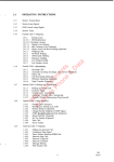
TABLE OF CONTENTS
I
SECTION 1
A.
SAFETY
B.
UNPACKING
C.
WATER
BEFORE
INSTALLING
CHECKS
PAGE
NO.
TESTS
4
GUIDES
THE WATER
SYSTEM
SECTION 2
6
TESTS
PLAN
YOUR
INSTALLATION
WHERE
TO INSTALL
B.
TOOLS,
PIPE AND FITTINGS,
C.
TYPICAL
SOLDERED
SECTION
3
SECTION 4
5
FILTER
A.
THE FILTER
7
OTHER
COPPER
MATERIALS
(OR CPVC)
PUT THE AUTOMATIC
STEP
BY STEP
INLET-OUTLET
GUIDES
B.
INSTALLING
C.
LOCATE
D.
CONNECT
E.
PRESSURE
TEST - CHECK
FOR LEAKS
R
GROUNDING
- CONNECT
TO ELECTRICAL
THE WATER
ADAPTORS,
OR PLASTIC
WATER
IN AND OUT PIPES
9
BYPASS
VALVE
11
12
BYPASS
AND CONNECT
DRAIN
AND THREADED
TO INSTALL
ASSEMBLE
3-VALVE
8
NEEDED
IRON FILTER TOGETHER
A=
RESTART
AND
13
FILTER
14 - 15
HOSES
16
POWER
HEATER
17
18
3
SECTION 1
BEFORE
INSTALLING
CHECKS
I
1A.
SAFETY
GUIDES
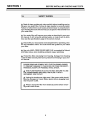
• Read all steps, guides and rules carefully before installing and using your new water filter. Follow all steps exactly to correctly install.
Failure to follow them could cause personal injury or property damage. Reading this book will also help you to get all of the benefits from
your water filter.
• Your water filter will improve your water as described in your owners manual. It will not purify polluted water, or make it safe to drink.
Also see the specifications page in the owners manual.
• Check with your local public works department for plumbing, electric and sanitation codes. You must follow their guides as you install
your filter.
• Use only LEAD-FREE SOLDER AND FLUX, as required by Federal
and State codes, when installing soldered copper plumbing.
•
Protect the filter and piping from freezing. Damage from freezing
voids the filter warranty. See how to protect from freezing in your owners manual.
PLEASE READ AND COMPLY WITH THE FOLLOWING GUIDES
TO PREVENT DAMAGE TO THE FILTER OR OTHER PROPERTY,
PERSONAL INJURY, OR POSSIBLE FATAL SHOCK.
• THIS FILTER WORKS ON 24 VOLTS ONLY. BE SURE TO USE
THE TRANSFORMER INCLUDED, AND PLUG IT INTO A
GROUNDED 120V OUTLET.
•
Unplug the transformer right away if the power cable should
become damaged or frayed. Make repairs before plugging back
into the power outlet.
• Always unplug the filter from electrical power before removing outer valve covers.
4
AND TESTS
SECTION 1
BEFORE
INSTALLING
CHECKS
AND TESTS
I
lB.
UNPACKING
THE WATER
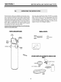
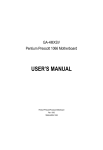
Packed with the filter are installation and owners manuals, an electrical transformer and a bag of several small
parts. Automatic Iron Filter models also include a feeder
valve and the other parts shown below. You will use all of
these parts while installing the filter. So you don't lose any
parts, keep in a safe place until you are ready to use
them. Remove the filter from the master carton. Discard
all cardboard
FILTER
Use care when handling the filter. DO NOT turn upside
down. DO NOT drop, or set on sharp objects that could
make a hole in the bottom. The water filter is heavy and
to avoid damage, or personal injury, do not try to lift it or
move more than necessary. See page 13, when you are
ready to move it into installation position.
and foam packing pieces.
Check the filter for shippinq damaqe. If you find damaqe,
report it to your Sears store.
PARTS
DESCRIPTIONS
SMALL
PARTS
TOP
COVER
VALVE
ASSEMBLY
_
INLET-OUTLET
ADAPTOR(2)
0
O
CLIP
(2)
FACE
TIMER
SHROUD
RESIN
TAN K
GROUND CLAMP
OTHER PARTS OF AUTOMATIC
ONLY
IRON FILTER
__FEEDER
TUBING_
NUT-FERRULE
__
(3)_1
_
P EROM
TsT_ I_UENMATIE
BA_E
5
VALVE
I
SECTION 1
BEFORE
INSTALLING
CHECKS
AND TESTS
I
1C.
WATER SYSTEM
HAS YOUR WATER SUPPLY HAD A CHEMICAL ANALYSIS? Please see page 2.
TESTS
CHECK YOUR WATER FLOW RATE - A water flow of
5-1/2 to 7 gallons per minute is needed. A lower flow will
keep you filter from working as well as it should. To make
an easy check of your flow rate, do the following. You will
need a one gallon container (can, jar, pail, etc.).
CHECK YOUR WATER PRESSURE - For your filter to
work correctly, a water pressure of no lower than 20
pounds per square inch (psi) is needed in the house water pipes. The highest pressure allowed in the water
pipes is 125 psi. If pressure is over 125 psi, buy and install
a pressure reducing valve in the water inlet pipe and pipe
to the filter.
1. Fully open two cold water faucets close to the point
water enters the house.
2. With both faucets open, fill the gallon container at one
faucet while looking at a watch or clock to see how many
seconds it takes.
NOTE:
3. Empty the container and go to the second faucet (be
sure BOTH faucets are still on). Fill the gallon container
at the second faucet and see how may seconds it takes.
If water pressure during the day is 100 psi or more, pressure during the night may go over 125 psi...Adding a
pressure reducing valve may reduce the flow.
4. Turn off both faucets. Now add the number of seconds
it took to fill the container at both faucets.
If you have a well water system, look at the pressure
gauge to find the water pressure. Call you local water department if you have city water. They will tell you what the
water pressure is where you live.
5. A total of 35 seconds, or less, means the system flow
rate is good.
FOR FUTURE REFERENCE, ENTER RESULTS OF YOUR WATER SYSTEM TESTS IN THE "FACTS AND FIGURES TO
KEEP" TABLE IN YOUR OWNERS MANUAL.
6
SECTION 2
PLAN YOUR
INSTALLATION
I
2A.
WHERE
TO INSTALL THE FILTER
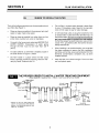
Think of the following points as you choose a place to put
your filter (See Figure 1).
•
•
Put the filter in a place water damage is lease likely
to occur if it develops a leak. Sears or the manufacturer will not repair or pay for water damage.
Place as close as possible to the pressure tank (well
water) or water meter (city water).
A 120V electrical outlet, to plug the transformer into
is needed within 10 feet ofthe filter (the filter has a 10
foot power cable). Be sure the outlet and transformer
are in an inside place, to protect from wet weather.
Sothe filter always has electrical power, use a continuously "live", grounded outlet, that cannot be accidently switched off.
Place as close as possible to a water drain such as
a floor drain, laundry tub, sump or standpipe.
Connect to the house main water pipe BEFORE THE
WATER HEATER. Temperature of water going
through the filter must not be more than 120°F
(49°C).
•
If a water softener, or other filter is installed, locate in
the order shown in Figure 1, below.
•
DO NOT install in a place where the filter could
freeze. Damage caused by freezing voids the warranty by Sears, Roebuck and Co.
When installing in an outside location, you must take
the steps necessary to assure the filter, installation
plumbing, and wiring, are as well protected from the
elements, contamination, vandalism, etc., as when
installed indoors.
Keep the filter out of direct sunlight. The sun's heat
can melt plastic parts.
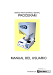
THE PROPER ORDER TO INSTALL WATER TREATING
(Shows sequence
,_
of equipment
only -- seldom,
EQUIPMENT
if ever, would all items be needed)
kitchenor bathroom
COLDfaucet
Sediment
or
Taste & Odor _'_
Cartridge
11
Filter
L_)
cold-softwater _
hardwa(erto
outside
hot-soft waterwater_
,_
Phosphate,
de
_-
peer
I
_
_
,_
--
-_
L__J
}
__ =___
Taste&
Water
Odor
Softener
*Always put the Iron Filter before the
softener, the Taste & Odor Filter after the
softener, the Neutralizer before an Iron
Filter, etc., as shown.
Filter
j
r_
I]
I
I
II
l
]
l
L__J
Auto.
Iron
Filter
OR
t
=
[i
city watersupply
!
I
_
/!
heater____
_I
|_---
__
Neutralizer
Im
_
J
I
I
_
......
I/
_
I
pressure or
I L_i__I
air
Sed,ment i..,,,,.,_U_
l Cartridge
_
Auto.
Clarifier
Filter
(optional
location'
bler_dina
I __
-"{'anl_'_
lr]
q
well
we
,LU--4 water
i
Solution
Dispensing
7
captive
System
SECTION 2
PLAN YOUR
INSTALLATION
I
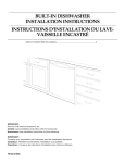
2B.
TOOLS, PIPE AND FITTINGS, OTHER MATERIALS NEEDED
You must first decide how to run in and out pipes to the
filter. Look at you house main water pipe at the point you
will connect the filter. Is the pipe soldered copper, glued
plastic, or threaded galvanized or brass? What is the pipe
size? What kind of pipe and fittings is it easiest for you to
work with, and what tools do you have?
_-" A drain hose is needed to carry away backwash discharge water, from the filter, to a drain point (see step
1 on page 14). The filter is factory equipped with a
drain fitting that accepts either 5/8" inside diameter
(I.D.) hose onto a barb, or a length of 5/8" minimum
I.D. garden hose. You can buy a 15 ft. length of garden hose from Sears, Stock No. 42-3431.
NOTE: Flexible hose is not allowed by some codes. If a
rigid drain is required, most hardware stores carry adaptors, garden hose on one end and sweat or pipe thread
on the other.
Now look at the common plans for in and out piping on
page 9. Select the drawing best for you and use it as a
guide to plan what materials you will need. As you plan
your in and out piping, keep in mind the following check
list. Then get all the materials you will need before you
start.
_-" TOOLS NEEDED: - Common and cross point (Phillips) screw drivers, slip joint pliers and a tape measure or rule.
...for SOLDERED COPPER - tubing cutter, propane
torch, solid core LEAD FREE solder, paste flux,
emery cloth, sandpaper or steel wool.
_-" In and out pipes to the filter must be at least 3/4" size.
Some local codes may tell you to use no less than 1"
pipe size (see note, below).
...for THREADED PIPE - hacksaw or pipe cutter,
pipe wrenches, pipe threading tool, pipe joint compound approved for use on potable water.
_-" Use copper, brass, or galvanized pipe and fittings.
Some codes may also allow CPVC plastic pipes.
...for CPVC PLASTIC - hacksaw, adjustable wrench,
solvent cement approved for use on potable water,
primer.
_-" Copper and galvanized pipe corrode quickly when
connected together. Use pipe and fittings of the
same material.
NOTE, FOR 1" PLUMBING
CONNECTIONS
...SOLDERED COPPER - Buy two sweat adaptors (1" female
thread x 1" sweat) and plumb directly to the inlet-outlet adaptors
or bypass valve. Threads on the inlet-outlet adaptors and bypass
valve are 1" pipe thread.
_-" You can buy adaptors to go from a copper or
threaded main water pipe to CPVC in and out pipe.
...see
_A_and _B_i. Do not use the installation kit, Sears Stock No.
42-3441,
_-" Sears has kits and bypass valves you can buy to help
make installing your filter easier...see page 9.
or the flexible
conntectors,
Sears
Stock
No. 42-3440.
CAUTION:
DO ALL SOLDERING BEFORE CONNECTING SWEAT ADAPTOR
TO INLET-OUTLET ADAPTORS OR BYPASS VALVE.
ALWAYS install a bypass valve or valves. Either use
three shut off valves, or Sears special valve. Bypass
valves let you turn off water to the filter, but still have
water in the house pipes.
...THREADED PIPE - Use a 1" threaded straight connector
of the reducer fitting shown in _C_.
8
in place
SECTION
2
PLAN YOUR
INSTALLATION
I
I
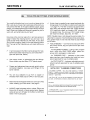
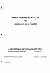
2C.
(_
TYPICAL
IN ANDA OUT
PLUMBING
3 VALVE
BYPASS USING
(SOLDERED OR CPVC PLASTIC)
o_ts_de
III
Shut-off
T
FI'__
_
I
PLUMBING
USING
SEARS
BYPASSSPECIAL
VALVE PLASTIC
(SOLDERED OR CPVC PLASTIC)
YPASS VALVE (Plastic)
Sears Stock No. 42-3437
Water
One, easy working valve takes the
place of 3 separate valves.
III
II
I II
I
OUT
_,
Ill
FITTINGS
REQUIRED NOT
IDENTIFIED
INSTALLATION KIT
Sears Stock No. 42-3441
90 ° Elbow
I
IP,pe/a,
re I.)
* 1" NPTX
3/4" Sweat
Reducer (2)
OUT
[11
L
'ves
T.ee(2)
IN AND
SEARS KITS AND VALVES
TO MAKE INSTALLING
YOUR FILTER EASIER
FITTINGS[ '.\ I II
90" Elbow (4)
IN AND OUT PIPES TO FILTER
SWEAT ADAPTORS IN_I_ AND.\B
.F'_:/
OUl
* 1" NPT X
3/4" Sweat
Reducer (2)
F ~l-.I.
I II_
I II
FLEXIBLE CONNECTORS
Sears Stock No. 42-3440
I I I llkJ
o,.,,,et
\
"l I1_'
""--Adapt°r
kk& _
J F_J"
-..
._ _
(2)
Pipe (as reg.)
USE TO REPLACE THE 1" X 3/4"
Outlet
N
/
_
Allows easy hook up even if
pipes are not exactly aligned.
NPT
(CHECK LOCAL PLUMBING CODES)
VALVE
FILTER__dlanlpltor.1
- N pT __
__
OUT PIPES, AT DOTTED
LINE, DIRECTLY TO
THE INLET AND
OUTLET ADAPTORS
OR TO BYPASS
ONNECT
VALVE
El. FROM
SEE@,IN-
FILTER
j
Inlet
IN AND PLASTIC
OUT PLUMBING
SEARS
BYPASS USING
VALVE
(THREADED PIPE)
® ,AND_€).
Outside
Faucets
(Ra w
CROSS-OVER
In)
FITTINGS
REQUIRED NOT
IDENTIFIED
90° Elbow (2)
Union (2)
Pipe (as reg.)
USE IF WATER SUPPLY
IS FROM THE LEFT
OUT
IN
÷
Outlet
x 34" reducer*
s
FILTER
9
VALVE
SECTION
3
PUT THE AUTOMATIC
IRON FILTER TOGETER
I
I
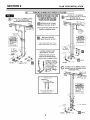
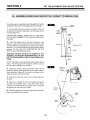
3A. ASSEMBLE
FEEDER VALVE AND BOTTLE,
CONNECT
TO MINERAL
TANK
IF INSTALLING A CLARIFIER, NEUTRALIZER OR TASTE
& ODOR FILTER, SKIP THIS PAGE AND GO TO PAGE 11.
1. At the location you have chosen to install the filter, lift
and set the mineral tank assembly onto the larger end of
the base (Figure 3).
mineral
tank ---....
assembly
CAUTION: BE CAREFUL WHEN YOU LIFT THE TANK,
AS IT IS HEAVY. DO NOT LIFT BY THE VALVE OR VALVE
COVERS.
2. Check the feeder valve to be sure the large o-ring
seal is in place on the underside. Then remove the cap
from the bottle and carefully turn the valve into the bottle.
After the o- ring just touches the top of the bottle, tighten
another 1/8 turn. DO NOT OVERTIGHTEN OR THE
BOTTLE WILL DEFORM AND LEAK.
shroud -"
O-Ring,
37/8" I.D.
bottle
WARNING: HANDLE THE BOTTLE CAREFULLY. THE
POWDER (POTASSIUM PERMANGANATE)
IN THE
BOTTLE STAINS DEEPLY. KEEP IT AWAY FROM CHILDREN.
NOTE: The bottle is only partly filled with powder (about
6 Ibs.). The empty part of the bottle is needed so it can
fill with water to dissolve the powder.
nozzle and
3. Shake the bottle to level the powder. Then set the
bottle and feeder valve assembly into the base, next to
the mineral tank (Figure 3). You can turn the base ro the
bottle is on either side of the tank.
venturi
_
housing
/
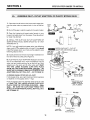
4. Remove the filter top cover (held in place with four
screws).
/
I
t
nut-ferrule
5. Take the 4 ft. length of 5/16" O.D. plastic tubing and
connect it to the feeder valve, and to the nozzle venturi
housing on the filter (Figure 4). Tighten the nut-ferrules
as tight as you can with your fingers.
SAc"O.D.
tubing
6. Carefully replace the top cover, aligning with the faceplate, and install the four screws.
feeder
valve
vent to
drain
10
SECTION 4
STEP BY STEP GUIDES
TO INSTALL
I
I
4A.
ASSEMBLE
INLET-OUTLET
ADAPTORS,
OR PLASTIC
BYPASS VALVE
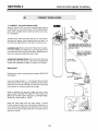
1. Close the shut off valve on the house main water pipe,
Shutoff
Valve
Shutoff
near the water meter or pressure tank, to turn off the water.
_=-_.
Pressure
I
,q_ Tank
2. Shut off the gas or electric supply to the water heater.
_
3. Open the highest and lowest water faucets in your
house to let water drain from the pipes. Close faucets after water has drained.
-" Water
Meter
_[e] kl
Pump
Electrical
Panel
4. INSTALL THE INLET AND OUTLET ADAPTORS OR
SEARS BYPASS VALVE, SEARS STOCK NO. 42-3437
(FIGURES 6 & 7).
NOTE: If you will install the bypass valve (use following
steps a and c), the adaptors are not used. If you do not
install the bypass valve, you must use the adaptors (use
following steps a and b).
INSTALLING
ADAPTORS
luu_=tJ=
ILTER, WITH
"OP COVEF
INLET - OUTLET
OR BYPASS VALVE
) Clip (2)
8. Visually check and remove any foreign materials from
the valve inlet and outlet ports (Figure 6).
b. INLET AND OUTLET ADAPTORS (Adaptors and clips
are on the cardboard liner). Push the adaptors into the
valve inlet and outlet ports as far as they will go. Both
adaptors are the same and fit either valve port. SNAP
THE TWO LARGE HOLDING CLIPS INTO PLACE
FROM THE TOP DOWN AS SHOWN. CAUTION ... BE
SURE THE CLIPS SNAP FIRMLY INTO PLACE SOTHE
ADAPTORS WILL NOT PULL OUT ... GO TO PAGE 12.
Valve Outlet
/
or
f
BYPASS VALVE
Stock No. 42-3437
C. BYPASS VALVE, STOCK NO. 42-3437
If not already done, put a light coating of silicone grease
or Vaseline on the bypass valve o-rings.
NOTE:
TURN BYPASS VALVE
UPSIDE DOWN TO
CONNECT TO FLOOR
LEVEL PLUMBING
Push the bypass valve into the filter valve as far as it will
go. SNAP THE TWO LARGE HOLDING CLIPS INTO
PLACE, FROM THE TOP DOWN AS SHOWN ... CAUTION ... BE SURE THE CLIPS SNAP FIRMLY INTO
PLACE, SO THE BYPASS VALVE WILL NOT PULL OUT.
GO TO PAGE 13.
SIDE VIEW
END VIEW
CLIP--
.........
_'_i"
Valve Body
Inlet or Outlet
11
Installation Adaptor
or
Bypass Valve
(Push all the way in)
SECTION 4
STEP BY STEP GUIDES
TO INSTALL
I
4B.
INSTALL THREE
VALVE BYPASS
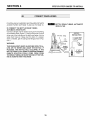
1. INSTALLING THREE VALVE BYPASS AND PIPES
BYPASS
VALVE
(FIGURE 8).
3-VALVE BYPASS
(_readedplumbingshown)
a. Cut the house main water pipe where you will connect
the filter. Loosely put together pipe, fittings and the three
valves. Place valves within easy reach.
IMPORTANT: WHEN LOOKING AT THE FRONT OF THE
FILTER, THE INLET IS ON THE RIGHT SIDE. IFTHE WATER IN YOUR HOUSE MAIN WATER PIPE RUNS FROM
LEFTTO RIGHT, BE SURE TO USE A "CROSS OVER" AS
SHOWN ON PAGE 9.
b. When all pipe, fittings and valves make a food fit together, tighten all threaded joints (use pipe dope on outside threads), or solder.
ITo
Filter
Inlet
12
SECTION 4
STEP BY STEP GUIDES
TO INSTALL
I
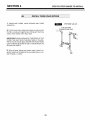
4C.
LOCATE FILTER AND CONNECT
PIPES
1. MOVE THE FILTER INTO PLACE
Carefully rock the filter, back and forth, and move the filter
into position. So the filter stands straight, be sure the surface it sets on is level and smooth. If needed, put apiece
of 3/4" plywood under the filter. Then put spacers under
the plywood to level the filter. DO NOT PUT SHIMS OR
SPACERS DIRECTLY UNDER THE TANK, (OR UNDER
THE AUTOMATIC IRON FILTER TANK BASE), WITHOUT
THE PLYWOOD. THE FILTERS WEIGHT MAY CAUSE
THE OUTER SHROUD, OR THE TANK BASE, TO BREAK
OR PUNCTURE.
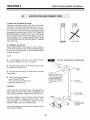
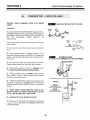
2. CONNECT THE FILTER
Read the IMPORTANT note on page 12. Then, measure,
cut (thread if needed) and put all pipe and fittings together up to the main water pipe, or to the bypass valve(s)
installed on page 12.
NOTE:
a. Include adaptors, reducers, union fittings, *flexible
connectors, installation kit, etc., as needed.
I_[_
TYPICAL
SOLDERING
CONNECTION
b. Cut pipe lengths exact for correct aligning, and to prevent stress on the filter valve.
0. Use pipe joint compound
pipe threads.
or Teflon tape on outside
d. When all piping fits together ...
... solder all sweat fittings.
... prime and cement all CPVC joints.
... tighten all threaded joints.
CAUTION:
NEVER SOLDER FITTINGS WHILE CONNECTED TO
NON-METALLIC PARTS. WAIT UNTIL SOLDERED PIPE
HAS COOLED BEFORE CONNECTION (See Figure 9).
3).
BE VERY CAREFUL WHEN PUTTING PIPE FITTINGS
ONTO THE PLASTIC THREADS OF THE INLET-OUTLET ADAPTORS, OR THE BYPASS VALVE. DO NOT
CROSS THREAD. DO NOT OVERTIGHTEN.
"'J)
_
3. CAREFULLY,
onto bypass
and tighten.
*Flexible connectors are not allowed in all areas. CHECK
YOUR LOCAL CODES.
13
turn
valve
SECTION 4
STEP BY STEP GUIDES
TO INSTALL
I
4D.
CONNECT
DRAIN HOSES
1. CONNECT THE VALVE DRAIN HOSE
clip
Attach a length of 5/8" minimum inside diameter hose to
the filter and run to the floor drain or other suitable drain
point. Other suitable drains include a laundry tub, sump,
or a standpipe.
garden
hose
garden hose
threads
barbs
clamp
To attach drain hose at the filter (Figure 10), the drain fitting has both garden hose threads and a hose barb. Do
the following, depending on the type of hose you use.
OR
slides
onto
barbs
NOTE: WHEN USINGA GARDEN HOSE, CUT
THE BARBS FROM THE FITTING WITH A
HACKSAW (REMOVE FII-I-ING FROM VALVE
BEFORE C UI-IING).
GARDEN HOSE: Remove the drain fitting from the valve.
It is held in place by a plastic clip. Use a hacksaw to cut
the hose barbs from the end of the fitting. Replace the fitting in the valve and attach the drain hose.
\\
\\
NOTE: 15 FT. LENGTHS OF
GARDEN DRAIN HOSE IS
AVAILABLE FROM SEARS,
\'_
"""_
\'_% \STOCK
NO. 42-3431
-..\
HOSE ONTO BARB FITTING: Push the end of the hose
all the way onto the barbs. USE AND AUTOMOTIVE
CLAMP OR A SPRING CLAMP TO HOLD IT IN PLACE.
Hose
\
(5/8" I.D. minimum)
\\
\\
\\
\\
\\
IMPORTANT:
Flexible drain hose is not allowed in all areas. SEE NOTE
ON PAGE 8.
Todrain
Roor Drain
1-1/2" MINIMUM
AIR GAP
Leave an air gap of about 1 -1/2" between the end ofthe
hose and the drain. This gap is needed to prevent sewer
back flow into the filter. DO NOT put the end of the hose
into the drain or connect without an air gap.
point other
than floor
drain. Support
hose in place
as needed.
STANDPIPE
Place or support the hose so it does not kink or have
sharp bends. FASTEN THE END OF THE HOSE TO A
BRICK OR OTHER HEAVY OBJECT SO WATER PRESSURE WILL NOT MAKE IT "WHIP".
r gap
1%"
Keep the hose lower than the drain fitting. In some
homes, to get to a drain you must raise the hose and run
it over head. If you need and over head drain, do not raise
the hose more than 8' above the floor or the filter will not
work as it should.
14
air gap
SUMP
SECTION 4
STEP BY STEP GUIDES
TO INSTALL
I
4D.
CONNECT
DRAIN HOSES
IF INSTALLING A CLARIFIER, NEUTRALIZER OR TASTE
& ODOR FILTER, SKIP PAGE 15 AND GO TO PAGE 16.
BOTTLE DRAIN TUBING,
IRON FILTER
AUTOMATIC
2. CONNECT THE BOTTLE DRAIN TUBING
AUTOMATIC IRON FILTER
Connect a length of 5/16" plastic tubing to the vent fitting
on the feeder valve (Figure 11) using a nut ferrule. Put the
other end of the tubing over the drain and fasten it to the
valve drain hose so it stays over the drain. If a copper
drain is needed, get the tubing and fittings shown it Figure 11.
COPPER
BOTTLE DRAIN
1/4" Copper (Hard
or Soft) Tubing
_
WARNING:
THIS DRAIN (VENT) MUST ALWAYS BE OPEN TO ALLOW AIR TO ENTER AND LEAVE THE BOTTLE. IF
PLUGGED, THE BOTTLE WILL COLLAPSE. IF THE
BOTTLE OVER FILLS, SOME POTASSIUM PERMANGANATE SOLUTION COULD COME FROM FROM
THE DRAIN TUBING. BE SURETHE END OFTHETUBING IS ALWAYS OVER THE DRAIN.
_5/16"
d_. 1 O.D. Tubing
_1 IIII I1_ _
_1 IIII I_d_----
To Drain
Point
straight
connector
i
Compression
Adaptor
15
SECTION 4
STEP BY STEP GUIDES
TO INSTALL
I
4E.
TESTING
LEAKS.
YOUR
PLUMBING
PRESSURE
WORK
TEST - CHECK
FOR LEAKS
FOR WATER
MAIN WATER
SHUTOFF
VALVES
CAUTION:
Shutoff
TO AVOID WATER OR AIR PRESSURE DAMAGE TO FILTER INNER PARTS, ATTO FLUSH PIPE CHIPS OR OTHER RESIDUE FROM THE WATER PIPES, BE SURE TO
DO
THE
FOLLOWING
STEPS
EXACTLY
AS
INSTRUCTED.
_}
- '-4._"__
'" Water
Meter
Shutoff
_--_.,,
Pressure
Look at the picture in Figure 13 showing your kind of bypass valve(s).
1. Fully open two cold, filtered water faucets nearby the
filter.
Well//'-_
Pump
2. Place bypass valve(s) in "bypass" position. On a
single valve, slide the stem into BYPASS. On a three valve
system, close the inlet and outlet valves and open the bypass valve.
ilt]
BYPASS VALVE (S)
FILTERED WATER SERVICE/HARD WATER BYPASS
SINGLE-PLASTIC
3. Fully open the house main water pipe shut off valve.
Observe steady water flow from both open faucets.
PULL
STEM
OUTWARD
FOR
4. Place bypass valve(s) in "Service", EXACTLY as follows. KEEP FILTERED WATER FAUCETS OPEN.
SERVICE
SINGLE BYPASS VALVE: SLOWLY slide the valve
Push
InwarO
stem towards "Service", pausing several times to allow
the filter to pressurize slowly.
Bypass
a.
I'
For
b. THREE VALVE BYPASS: Fully close the bypass valve
and open the outlet valve. SLOWLY open the inlet valve,
pausing several times to allow the filter to pressurize
slowly.
_VALVE
SERVICE
Close Bypass Valve
Open Inlet & Outlet Valves
BYPASS
5. AFTER ABOUT THREE MINUTES, OPEN A HOT
WATER FAUCET FOR ABOUT ONE MINUTE, OR UNTIL ALL AIR IS EXPELLED, THEN CLOSE.
Open Bypass Valve
Close Inlet & Outlet Valves
6. CLOSE BOTH COLD WATER FAUCETS.
7. Check your plumbing work for leaks and fix right away
if any are found. BE SURE TO OBSERVE PREVIOUS
CAUTION NOTES.
16
Inlet
Valve
SECTION 4
STEP BY STEP GUIDES
TO INSTALL
I
41=. GROUNDING,
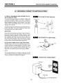
1. INSTALL GROUNDING
TER IN AND OUT PIPES
CONNECT
TO ELECTRICAL
WIRE BETWEEN THE FIL-
POWER
COLD WATER
PIPE GROUND
The house cold water pipe (iron or copper) is often used
to ground all electric outlets in the home. Outlets are
grounded to protect you from shock when you touch any
electric appliance plugged into the outlet. If you didn't
install a three valve bypass (Figure 13), the cold water
pipe ground is broken.
To restore the ground, install the ground clamp to the inlet and outlet pipes. Be sure the pipes are clean under
the clamps and wire for good contact.
ground clamp
IMPORTANT:
inlet - outlet
Be sure the cold water pipe has direct metal to metal contact all the way to the ground. Plastic, rubber or other
electrically insulating parts such as hoses, fittings, washers or gaskets can break the direct metal to metal contact. Also check the water meter (city water) or the well
pump. Install a #4 copper jumper wire, clamped tightly
on both ends, across insulated parts (Figure 15).
WATER
2. ELECTRIC POWER OUTLET FOR YOUR FILTER
Water
METER
JUMPER
WIRE
Meter
The filter works on 24 volt, 60 Hz electric power. The included transformer changes standard 120 volt AC house
power to 24 volts. You must plug the transformer into a
grounded, 120 volt outlet only. Be sure the outlet is always "live" so someone cannot turn it off by mistake.
#4 Groundwire
NOTE:
The included transformer is made for inside use only. Be
sure the electrical outlet you plug the transformer into is
inside, to protect from weather (see page 7).
CONNECTING
TRANSFORMER
Transformer
_'_'_
I
% P°TCab'. __el_
17
120V-60Hz
I\L-_ll/t I I!
Electrical
II_P._!
from Face Plate_.iqmer
SECTION 4
STEP BY STEP GUIDES
TO INSTALL
I
RESTART
THE WATER
HEATER
TURN ON THE GAS (OR ELECTRIC) SUPPLY TO THE WATER HEATER AND LIGHT THE PILOT.
NOTE:
filtered water. If you don't drain it, it will take a few days
before you have fully filtered water.
Your new Sears filter is now filtering the water for your
household needs. However, your WATER HEATER is
filled with unfiltered water. To have fully filtered water
right away, you can drain the water heater so it refills with
To drain the water heater, open a hot water faucet and let
it run until the water turns cold. Then close the faucet.
YOUR PLUMBING AND ELECTRICAL WORK IS COMPLETE. NOW GO TO YOUR OWNERS MANUAL AND DO THE
FILTER START UP STEPS ... setting the timer, sanitizing, etc.
18
19
20