1
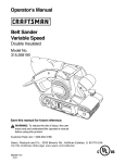
Owners
Manual
FOR POTABLEWATER
HEATING ONLY
NOT SUITABLE FOR
SPACEHEATING
NOT FOR USE IN
MOBILE HOMES
Model No.
153.337113
153.337162
153.337213
153.337262
153.337362
153.337413
153.337462
153.337513
153.337562
153.337613
153.337662
153.337762
153.337862
153.337960
50 Gal. Short High Altitude
50 Gal. Short
40 Gal. Short High Altitude,
40 Gal. Short
30 Gal.
40 Gal. High Altitude
40 Gal.
POWER
GAS
• Safety
MISERTM9
WATER
Instructions
• Care
• Installation
• Operation
For Your Safety
65 Gal, High Altitude
65 Gal.
AN ODORANT
IS ADDED
WATER HEATER
WARNING:
and Maintenance
• Troubleshooting
• Parts List
50 Gal. High Altitude
50 Gal.
50 Gal. High Recovery
65 Gal. High Recovery
H EATER
TO THE
If the information
BY THIS
in these instructions are not fol-
lowed exactly, a .fire or explosion
damage, personal ,nlury or death.
40 Ga!.(LP.)
GAS USED
may result,
causing property
-Do not store or use gasoline or other flammable vapors and liquids in the vicinity of t_is or any other appliance.
-WHAT TO DO IF YOU SMELL GAS
Do not try to light any appliance.
Do not touch any electr,'cal switch; do not use any phone in your
building.
.
.
Immediately
call your I_as supp.her from a ne,ghbor's phone.
i Follow the gas suppliers instructions.
If you can not reach your gas suppl,er, call the fire department.
-Installation and service must be performed by a qualified installer,
service agency or the gas supplier.
CauUon:
Read and Follow
All Safety Rules and
Operating Instructions
Before First Use of
This Product.
•
.
]
AWARNING
Improper installatmn, adlus_on
, service or maintenance I
can cause DEATH, SERIOUS BODILY INJURY, OR PROPERTY DAM- I
AGE. Refer to this manual for assistance or consult the local Sears I
Service Center or gas utility for further reformation.
J
Flammable vapors may be drawn by air currents from other areas
&WARNING
t
of the structure to this appliance.
Savethis Manual for Future Reference.
Sears,
Roebuck
AWARNING
READ THE GENERAL SAFETY SECTION BEGINNING ON INSIDE
COVER AND THEN THIS ENTIRE MANUAL BEFORE INSTALLING
OR OPERATING THIS WATER HEATER•
and Co.,
Hoffman
Estates,
IL 60179
U.S.A.
Safety Precautions
AWARNING
AWARNING
At the time of manufacture this water heater was provided with a combination temperature-pressures relief valve
certified by a nationally recognized testing laboratory
that maintains periodic inspection of production of listed
equipment or materials, as meeting the requirements
for Relief Valves and Automatvc Gas Shutoff Devices for
Hot Water Supply Systems, and the latest edition of
ANSI Z21.22 and the code requirements of ASHE. If
replaced, the valve must meat the requirements of local
codes, but not lessthan a combination temperature and
pressure relief valve certified as meeting the requirements for Relief Valves and Automatic Gas Shutoff
Devices for Hot Water Supply Systems, ANSI Z21.22 by
a nationally recognized testing laboratory that maintains
periodic inspection of production of listed equipment or
materials.
The valve must be marked with a maximum set pressure
not to exceed the marked hydrostatic working pressure
of the water heater (I 50 IbsJsq. in.) and a discharge
capacity not less than the water heater input rate as
shown on the model rating plate. (Electric heaters watts divided by 1000 x 3415 equal BTU/Hr. rate.)
[Your local jurisdictional authority, while mandating the
use of a temperature-pressora
relief valve complying
with ANSI Z21.22 and ASME, may require a valve model
different from the one furnished with the water heater.
Compliance with such local requirements must be satisfied by the installer or end user of the water heater with
a locally prescribed temperature-pressure
relief valve
installed in the designated opening in the water heater in
place of the factory furnished valve.
For safe operation of the water heater, the relief valve
must not be removed from it's designated opening or
plugged.
Tho temperatere-pressore
relief valve must be installed
directly into the fitting of the water heater designated
for the relief valve. Position the valve downwlu_l and provide tubing so that any discharge will exit only within 6 i
inches above, or at any distance below the structural
floor. Be certain that no contact is made with any live
electrical part. The discharge opening must not be
blocked or reduced in size under any circumstances.
Excessive length, over 30 feet, or use of more than four
elbows can cause restriction and reduce the discharge
capacity of the valve.
No valve or other ebstxuction is to be placed between
the relief valve and the tank. Do not connect tubing
ditec_ to discharge drain unlessa 6" air gap is provided.
To prevent bodily injury, hazard to life, or property damage, tho relief valve must be allowed to discharge water
in quantities should circumstances demand. If the discharge pipe is not connected to a drain or other suitable
means, the water flow may cause property damage.
The Discharge Pipe:
• Must not be smaller in size than the outlet pipe size of
the valve, or have any reduclng couplings or other
restrictions.
Must not be plugged or blocked.
Must be of"material listed fur hot water distribution.
Must be installed so as to allow complete drainage of
both the temperature-pressure
relief valve, and the
Improper installation, adjustment, alteration, service or I
maintenance can cause DEATH, SERIOUS BODILY
INJURY, OR PROPERTY DAMAGE. Refer to this manual for assistance or consult your local Sears Service
Center for further information.
I
AWARNING
WATER HEATERS EQUIPPED FOR ONE TYPE GAS
ONLY: This water heater is equipped for one type gas
only. Check the model rating plate near the gas control
valve for the correct gas. DO NOT USE THIS WATER
HEATER WITH ANY GAS OTHER THAN THE ONE
SHOWN ON THE MODEL RATING PLATE. Failure to
use the €orrect gas can cause problems which can result in
DEATH, SERIOUS BODILY INJURY, OR PROPERTY
DAMAGE. If you have any questions or doubts consult
your gas supplier or local utility.
4WARNING
INSTALLATIONS IN AREAS WHERE FLAMMABLE LIQUIDS (VAPORS) ARE LIKELY TO BE PRESENT OR
STORED (GARAGES, STORAGE, AHD UTILITY AREAS,
ETC): Flammable liquids (such as gasoline, solvents,
propane (LP) or butane, etc.), all of which emit flammable
vapors, may be improperly stored or used in such areas.
The gas water heater pilot tight or main burner can ignite
such vapors. The resulting flashback and fire can cause
death or serious burns to anyone in the area, _ well as
property d_magn,
i
If installation in such areas is your only option, then the
installation must be accomplished in a way that the pilot
flame and main burner flame are elevated from the floor
at least 18 inches. While this may reduce the chances of
!flammable vapors from a floor spill being ignited, gasoline
iand other flammable substancesshould never be stored or
used in the same room or erda containing a gas water
heater or other open flame or spark producing appliance.
NOTE: Flammable vapors may be drawn by air currents
from other areas of the structure to the appliance.
AWARNING
If this water heater will be used in beauty shops, barber
shops, cleaning establishments, or self-service laundries
with dry cleaning equipment, it is imperative that the
water heater or water heaters be installed so that €ombustion and ventilation air be taken from outside these
areas, Refer to the "Facts to Consider About the
Location" section of this manual and also the latest edition of the National Fuel Gas Code, ANSI Z223.1, also
referred to as NFPA 54 for specifics provided concernin
air required,
I
A WARNING
.
I
A fire can start if combustible materials such as cloth,ng,
cleaning ma_,
or flamm_de liquids are placed against I
or next to the water heater.
[
discharge l_e,
Must terminate at an adequate drain,
Host not have any valve between the relief valve and
tank.
Safety Precautions
_,WARNING
_WARNING
A gas water heater cannot operate properly without the
correct amount of air for combustion. Do not install in a
confined area such a closet, unless you provide air as
shown in the "Facts to Consider About the Location" section. Never obstruct the flow of ventilation air. If you have
any doubts or questions at all, call your gas company.
Failure to provide the proper amount of combustion air
can result in a fire or explosion and can CAUSE DEATH,
SERIOUS BODILY INJURY,OR PROPERTY DAMAGE.
This water heater must not be installed directly on carFeting. Cerpe_ag must be protected by a metal or wood
panel beneath the appliance extending beyond the full
width and depth of the appliance by at least 3 inches
(76.2mm) in any direction, or iftbe appliance is installed
in an alcove or c oset, the entire floor must be covered by
the panel. Failure to heed this warning may result in a
Ere hazard.
AWARNING
AWARNING
VENT DAMPERS - Any vent damper, whether it is operated thermally or otherwise must be removed if Its use
inhibits proper drafting of the water heater.
Thermally Operated Vent Dampers: Gas-fired water
heaters having thermal efficiency in excess of 80% may
*roduce a relatively low flue gas temperature. Such temperatures may not be high enough to properly open thermally operated vent dampers. This would causespillage
of
flue gasesand may cause carbon monoxide poisoning.
Vent dampers must bear evidence of certification as complying with the latest edition of American National
Standard ANSI Z21.68(ANSI Z21.66 & 67, respectively,
cover electrically and mechanically actuated vent
dampers). Before installation of any vent damper, consult
your local Sears Service Center or the gas utility for further nformat on.
HOTTER WATER CAN SCALD: Water heaters are
intended to produce hot water. Water heated to a ternperature which willsa_
clotheswashing, disk washing,
and other sanitizing needs can scald and permanently
injure you upon €ontac_ Some people ace more likely to
be permanently injured by hot water than other_ These
include the elderly, children, the infiPm, or physicailyimentally handicapped. If anyone usinghot water in your home
fits into one of these groups or if there Is a local code or
state Ilw requiring a certain temperature water at the hot
water tap, then you must take special precautions, In addition to usingthe lowest possible temperature setting that i
satisfiesyour hot water needs, a means such as a mixing I
valve, shouldbe used at the hot water taps used by these I
people or at the water heater. Mixing valvesare available
at plumbing supply or hardware stores. Follow manufacturers instructions for installation of the valves. Before
changing the fa_)ry setting on the thermostat, read the
'_l'emperature Regulation" section in this manual.
AWARNING
• The appliance and its Individual shutoff valve must be dis.
connected from the gall supply piping system during any
pressure testing of the gas system at test pressures In
excess of '/2pound per square inch (3.$kPa).
• The appliance
must be isolated
from the gas supply piping system by closing its individual manual shutoff valve
during any pressure testing of the gas supply piping system at test pressures equal or less than '/2 pound per
square Inch (3.SkPa).
A, WARNING
Soot build-up Indicates a problem that requires correction before further use, Turn "OFF" gas to water heater
and leave "OFF" until repairs are made, because failure
to correct the cause of the sooting can result in s fire or
Iexplosion causing DEATH, SERIOUS BODILY INJURY,
OR PROPERTY DAMAGE.
AWARNING
_,WARNING
Chemical vapor corrosion of the flue and vent system
may occur if air fur combustion contains certain chemical
vapors. Spray can propellants, cleaning solvents, refrigerator and air conditioner refrigerants, swimming pool
chemicals, calcium and sodium chloride, waxes, bleach,
and process chemicals are typical compounds which are
potentially corrosive.
BEFORE LIGHTING [PROPANE (L.P.) GAS WATER
HEATERS): Propane (L.R) gas is heavier than air. Should
there be a leak In the system, the gas will settle near the
ground. Basements, crawl spaces, skirted areas under
mobile homes (even when ventilated), closets and areas
below ground level will serve as pockets fur the accumulation of this gas. Before attempting to light or relight the
water heater's pilot or turning on a nearby electrical light
switch, be absolutely sure there is no accumulated gas In
the aceL Search for odor of gas by sniffing at ground level
in the vicinity of the appliance. If odor is detected, follow
steps indicated at "For Your Safety" on the cover page of
this manual then leave the premises.
I
_,WARNING
Obstructedor deteriorated vent systems may presenta
serioushealthriskor asphyxiation.
Safety Precautions continued on page 4.
3
Safety Precautions
I
A, WARNING
ACAUTION
WATER HEATERS EVENTUALLY LEAK: Installation of
t_ water heater must be accomplished in such a manner
that Iftho tank or any connections shouldleak, the flow of
water will not causedamage to the structure. When such
locations cannot be avoided, a suitable drain pan should
be instal ed under the water heater. Drain pans are wall.
at ynor load Sun s_re. Such a drain pan must be
not greater than 1½ Inchesdeep, havea minimum length
and width of at least 2 Inches greater than the water
heater dimensions and must be piped to an adequate
drain. The pan must not restrict combustion air flow,
Under no clrcumstences is the manufectumr or Sears to
be held liable for any water damage in connection with
this water heater.
J
The water heater with draft hood installed must be prop-[
erly vented to a chimney which terminates outdoors.]
Never operate the water heater unlessit is vented to the]
outdoors and has adequate air supply to avoid risks of[
Improper operation, explosionor asphyxiation.
[
AWARNING
Minimum clearances between the water heater end combustible con_ction
am I" at the sidesand rear, 4" at the
front, and 6 from the vent pipe. Clearence from the top
of the jacket is 18" on most models. Note that a lesser
dimension may be allowed on some models. Refer to the
label on the water heater adjacent to the gas control valve
for all clearances.
I
&WARNING
I
Do not use this _opllence if any part of It has been under I
water, immediately call a Sears Service Technician to I
inspect the appliance and to replace the gas control or any J
part of the burner system which has been under water.
I
&WARNING
HYDROGEN GAS: Hydrogen gas can be produced In a hot
water system that has not been used for a long period of
time (generally two weeks or more). Hydrogen gas is
exVemelyfl_mma_e _d mq_s_e. To preventthe pembility of injury under these conditions, we recommend the
hot water faucet be opened for several minutes at the
kitchen sink before any electrical appliances which
connected to the hot water system are used (suchas a dishwasher or washing machine). If hydrogen gas is present,
there will probably be an unusual sound similar to air
escaping through the pipe as the hot water faucet Is
opened. There must be no smoklnfl or open R_umenear
the faucet at the time It is open.
AWARNING
INSULATING JACKETS: When installing an external
water heater insulation jacket on a p.s water heater:
• DO NOT cover the temperature-pressure relief valve.
• DO NOT put Insulation over any part of the top of the
gaswater heater.
• DO NOT put insulation over the gas control wive or gas
control valve/burner coverpor any access areas to the
burner.
• DO NOT let insulation around the gas water heater to
get within 8 inches of the floor (air must get to the
burner).
• DO NOT cover or remove operating Instructions. and
safety related warning labels and materials affixed to tee
water heater.
Failure to heed this will result In the pesslbility of a fire or
explosion.
4
Table of Contents
Safety Precautions ..........................................................................................................
2_
Table of Contents .................................................................................................................
5
Customer Kesponslbllltles
.................................................................................................................
6
Product _pecmcauons .........................................................................................................
6
Materials and Basic Tools Needed ....................................................................
i..........................
7
T'_
_
ol_14e
o/,b
.
Materials Needed ......................................................................................................................................................................
Basic Tools ................................................................................................................................................................................
Installation
Instructions
7
7
......................................................................................................
8-16
Removing the Old Water Heater ...............................................................................................................................................
Facts to Consider About the Location .......................................................................................................................................
Combustion Air and Ventilation for Appliances in Unconfined Spaces ...................................................................................
Combustion Air and Ventilation for Appliances in Confined Spaces .......................................................................................
Water Piping ...........................................................................................................................................................................
Temperature-Pressure Relief Valve ...........................................................................................................................................
Filling the Water Heater ....................... ;..................................................................................................................................
Venting ..............................................................................................................................................................................
Gas Piping .........................................................................................................................................................................
Installation Checklist ..............................................................................................................................................................
8
9
10
10
11
12
13
13-14
14-15
16
"t)peratmg
_"
Instructions ...........................................................................................
17-19
Eighting ......... Z. ................................................................................................................................................................
Temperature Regulation ..........................................................................................................................................................
17-18
19
Serviceand ACtlustment ................................................................................................
20-22
Tank (Sediment) Cleaning_.......................................................................................................................
Venting System Inspection ......................................................................................................................................................
Burner Inspection ...................................................................................................................................................................
Burner Cleaning .....................................................................................................................................................................
L.E Gas Control Valve & Burner Assembly Replacement Information ....................................................................................
Draining .................................................................................................................................................................................
Temperature-Pressure Relief Valve Operat on
..............................................................................
Drain Valve Washer Replacement ...........................................................................................................................................
Housekeeping .........................................................................................................................................................................
Service ....................................................................................................................................................................................
"_
"lroubleshootlng
-" -
20
20
20
20
21
21
21
22
22
22
Guide .......................................................................................................
23-25
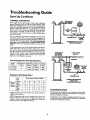
Start Up Conditions ...............................................................................................................................................................
v
Condensation ........................................................................................................................................................................
Smoke/Odor .........................................................................................................................................................................
Thermal Expansion ...............................................................................................................................................................
Strange Sounds ......................................................................................................................................................................
Operational Conditions ..........................................................................................................................................................
Smelly Water .........................................................................................................................................................................
Air in Hot Water Faucets ......................................................................................................................................................
High Temperature Shut Off System ......................................................................................................................................
Not Enough or No Hot Water ..............................................................................................................................................
Water is too Hot ...................................................................................................................................................................
Leakage Checkpoints ..............................................................................................................................................................
23
23
23
23
23
24
24
24
24
24
24
25
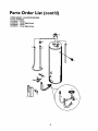
Parts Order List .....................................................................................................................
28-35
Customer
Thank
Responsibilities
You
_or purchasinga
Sears water heater.
Properly installed and maintained, it should give you years of
trouble free service. If you should decide that you want the new
water heater professionally installed by Sears call the local Sears
Service Center or any Sears store. They will arrange for prompt,
quality installation by Sears authorized contractors.
Abbreviations Found In This Instruction Manual
I.A,S. - International Approval Services, A Division of CSA
A.N.S.I, - American National Standards Institute
N.EEA. - National Fire Prevention Association
•
AWARNING
This gas-fired water heater is design certified by the
International Approval Services, A Division of CSA under
American National Standard/C$A Standard for Gas Water
Heaters AN$ Z21.10.1 • CSA 4.1 (latest edition). The
installation must conform with this manual, Local Codes
and with the latest edition of the National Fuel Gas Code,
ANSI Z223.1.
•
•
This publication is available from y_ur local government or
public library, gas company, or by writing NFPA.
Batterymarch Park, Quincy, MA 02269.
•
•
Read the _Safety Precautions" section, pages 2 through 4 of
this,manual first and then the entire manual carefiflly. If you
dont follow the safety rules, the water heater will not operate
properly. It could cause DEATH, SERIOUS BODILY
INJURY AND/OR PROPERTY DAMAGE.
This manual contains instructions for the installation,operation, and maintenance of the gas-fired water heater. It also
contains warnings through out the manual that you must read
and be awareoffAll warnings andall instructionsare essential
to the proper operation of the water heater and your safety.
Since we cannot put everything on the first few pages, READ
THE ENTIRE MANUAL BEFORE ATTEMPTING TO
INSTALLOR OPERATETHE WATER HEATER.
The installation must conform with the instructions in this
manual; gas company rules; and Local Codes, or in the
absence of Local Codes, with the latestedition of the National
Fuel Gas code, ANSI Z223.1, also referredto as NFPA 54.
This publication is available from your local governmentor
public library or gas company or by writing NFPA,
Battcrymarch Park, Quincy, MA 02269.
If a_er reading this manualyou have any questions or do not
understand any portion of the instructions, call the Sears
ServiceCenter.
_y
plan the place where you are going to put the water
heater. Correct combustion, vent action, and vent pipe instalhtion are very importan_ in preventing dear from possible
cathon monoxide poisoning and fires.
Examinethe locationto ensure the water heater complies with
the _Facrs to Consider About the Location"section in this
manual.
For California installation this water heater must be braced,
anchored, or strapped to avoid failing or moving during an
earthquake. See instructions for correct installation procedures. Instructions may be obtained from your local dealer,
wholesaler,public utilities or California Office of the State
Architect, 400 P Street, Sacramento, CA 95814.
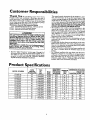
Product Specifications
MODEL NUMBER
153.337113
153.337162
153.337213
153.337262
153.337362
153.337413
153.337462
153.337513
153.337562
153.337613
153.337662
153.337762
153.337862
153.337960
TANK
CAPACITY
IN GALLONS
50
50
40
40
30
40
40
50
50
65
65
50
65
40
TYPE
OF
GAS
NATURAL
NATURAL
NATURAL
NATURAL
NATURAL
NATURAL
NATURAL
NATURAL
NATURAL
NATURAL
NATURAL
NATURAL
NATURAL
PROPANE
B,ZU.
RATE
40,000
40,000
40,000
40,000
40,000
40,000
40,000
40,000
40,000
40.000
40,000
52,500
50,000
40,000
RECOVEI_
RATE GAI&
PER HOUR
MINIMUM
VENT
PIPE
@9O°F8II;!_
40.9
3" or 4"
40.9
3"or 4"
40.9
3" or 4"
40.9
3"or 4"
40.9
3" or 4"
40.9
3" or 4"
40.9
3" or 4"
40.9
3" or 4"
3" or 4"
40.9
40.9
3"or 4"
40.9
3"or 4"
4"
53.7
4"
51.2
40.9
3"or 4"
DIMENSIONSIN INCHES
HEIGHT TO
)IAMETER JACKETTOP
22"
49"
22"
49"
20"
47½"
20"
47½"
16"
57½"
18"
58_A
"
lg"
5glA"
20"
58"
20"
58"
22"
59½"
22"
59½"
20"
58_A"
22"
18"
59½"
58¼"
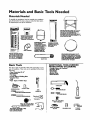
Materials
Materials
and Basic Tools Needed
Needed
/
To simplify the installation Sears has available the installation
_lsartsshown below.You may or maynot need all of these materi, depending-onyour type of installation.
WATER HEATER STAND 24"x24"xl 8"
FOR USE WITH WATER HEATERS
INSTALLED
IN RESIDENTIAL
GARAGES HAVING
A DIAMETER
24"
OR LESS AND A RATED CAPACITY
7S
GALLONS
OR LESS
WATER HEATER HEAT
TRAPS HELP REDUCE
NEAT LOSS DUE TO
THERMAL
SYPHONING
@
VENT
ELBOW
EXPANSION
TANKS
FOR THERMAL
EXPANSION
CONDITIONS AVAILABLE
IN
2 GALLON
AND $
GALLON
CAPACITY
THROUGN
LOCAL
SEARS STORE OR
SERVICE CENTERS
WATER NEATER INSTALLATION KIT WITH
FLEXIBLE CONNECTORS
FOR
314" OR 112" THREADED
OR COPPER PLUMBING
VENT
Basic Tools
You may or may not need all of these tools, depending on your
type of installation. These tools can be purchased at your local
Scrags store,
•
•
•
•
•
•
•
\
Pipe Wrenches (2) 14"
Screwdriver
Tin Snips
6 Foot Tape of Folding Rule
Garden Hose
Drill
Pipe dope or Teflon Tape
FLEXIBLE WATER
HEATER GAS CONHECTOR WITN
FITTINGS
DRAIN PANS AVAILABLE
IN 20"
DIAMETER
FOR WATER HEATERS
HAVING
A DIAMETER
18" OR LESS
AND AVAILABLE
IN 28" DIAMETER
FOR WATER HEATERS HAVING
A
DIAMETER
26" OR LESS
PIPE
ADDITIONAL
TOOLS NEEDED
WHEN SWEAT SOLDERING
•
•
•
•
•
•
Tubing Cutters or Hacksaw
Propane Torch
Sof_ Solder
Solder Flux
Emery Cloth
Wire Brushes
HACKSAW
GARDEN
HOSE
6 FOOT
TAPE
PiPE
WRENCH
SLOT-HEAD
$14" WIRE
C>--'"
SCREWDRIVER
I/2" WIRE
PHILLIPS
BRUSH
BRUSH
SCREWDRIVER
TIN
PROPANE
TORCH
SNIPS
ROLL OF LEAD FREE
SOFT SOLDER
ROLL OF TEFLON
TAPE
(USE ONLY ON WATER
CONNECTIONS)
PIPE DOPE (SQUEEZE
TUBE)
USE FOR WATER AND
_AS CONNECTIONS)
ROLL OF EMERY
CLOTH
SOLDER
FLUX
TUBING
CUTTER
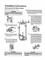
Installation
Instructions
Removing the Old Water
Heater
Turn _OFF" the gassupply to the water heater,
l
AWARN,N
I
If the main gasline--all
gasappliancesis
used, _lso shut 'doff'"the gasat each appliance. Leaveall
gasappliancesshut"off'" untilthe waterheaterinstallation
iscomplete.
@@
Turn _OFF" the water to the water
heater. Some installations require that
the water be turned off to the entire
house.
Check a_ain to make sure the gas supply
is OFF to the water heater. Then disconnect the gas supply connection from
the gascontrol valve.
Attach a hose to the water heater drain
valve and put the other end in a floor
drainor outdoors.Open the waterheater
drain valve. Open a nearby hot water
faucet which will relieve pressure in the
waterheater and speed draining.
I
AWARNING
The water passingout--valve
may be extremely
hot. To avoid being scalded, make sure all connections are I
i_.d
that the water flow is directed away from any I
Disconnect the vent pipe from the draft hood where
they connect to the water hearer. In most installations
the vent pipe can be lifted off afterany screw or other
attached devices are removed, Dispose of the draft
hood. The new water heater has the drafthood which
must be used for proper operation.
@ @
a. If you have copper piping to the water
heater, the two copper water pipes can
be cut with a hacksaw approximately
four inches away from where they connect to the water heater. This will avoid
cutting off the pipes too short.
Additional cuts can be made laterif necessary.Disconnect the temperature-pressure relief valve drain line. When the
water heater is drained,disconnect the
hose from the drain valve. Close the
drain valve. The water heater is now
completely disconnectedandreadyto be
removed.
b, If you have galvanized pipe to the water
heater, loosen the two galvanized pipes
with a pipe wrench at the anion in each
line. Also disconnect the piping remainlug to the water heater. These pieces
should be saved since they may be needed when reconnecting the new water
heater. Disconnect the temperature-pressure relief valve drain llne. When the
water heater is drained, disconnect the
hose from the drain valve. Close the
drain valve, The water heater is now
completely disconnected and ready to be
removed.
ACAUTION
Mineral buildup or sediment may have accumulated in the
old water heater. This causesthe water heater to be much
heavier than normal and this residue, if spilled out, could
causestaining.
I
Installation
Instructions
Facts to Consider
Location
About
the
You should carefully choose an indoor location for the new
water heater, because the placement is a very important consideration for the safety of the occupants in the building and for
the most economical use of the appliance. This water heater is
not for use in mobile homes or outdoor installation.
• The location selection must provide adequate clearances for servicing and proper operation of the waterheater.
AWARNING
This water heater must loot be installeddin_y on carpeting.
Carpeting must be protected by a metal or wood panel
beneath the appliance extending beyond the full width and
depth of the appliance by at least 3 inches (76.2mm) in any
direction, or if the applianceis installedin an alcoveor deset,
the entire floor must be coveredby the panel. Failureto heed
this warningmay resultin a fire hazard.
Whether replacing an old water heater or putting the water
heater in a new location, the following critical points must be
observed.
•
(cont'd)
The location selected should be indoors as close as practical
to the gas vent or chimney to which the water heater vent is
going to be connected, and as centralized with the water pipin._ system as possible. The water heater, as all water heaters
will eventually leak. Do not install without adequate
drainage provisions where water flow will cause damage.
AWARNING
Minimum clearances between the water heater and combustible construction are I" at the sidesand rear, 4" at the
front, and 6" frem the vant pipe.Clearancefrom the top of the
jacketis I8" on most modelg Note that a lesserdimensionmay
be allowed on some modelg Refer to the labelon the water
heater adjacantto the gascnotrel vaive for all dearance_
&CAUTION
WATER HEATERS EVENTUALLY LEAK: Installation of the
water heater must be accomplisbedin sucha manner that if
the tank or any connectionsshouldleak, the flow of water will
not causedan_ge to the structure. Wben suchIocatfonscannot be avoided, a soitalde drain pan shouldbe installedunder
the water buater. Drain pansm_eavailableat your local Sears
store. Such a drain pan must be lootgreater than I _ inches
deep, have a minimum length and width of at least 2 inches
12"M__
VENTILATION
greater than the water heater dimensionsand must be piped
i to an adequatedrain.The panmust not restrict combustionair
i Bow.Under no circumstancesis the manufacturer or Sears to
! be held liable for any water damage in connection with this
!water heater.
TOPP V_E'V,/
OF CLOSET
WITHOUT
AWARNING
DOOR
AIR DUCT
Figure I ]
INSTALLATIONS IN AREAS WHERE FLAMMABLE LIQUIDS
VAPORS) ARE LIKELY TO BE PRESENT OR STORED
GARAGES, STORAGE, AND UTILITY AREAS ETC):
qammable iquids(suchasgasoline,
solvents,propane (LP) or
butane, etc.), all of which emit flammable vapors, may be
improperlystored or usedin suchare_ The gaswater heater
_ot light or main burner camignitesuch vaporL The resul_ng
flashbackand fire can causedeath or seriousbumsto anyonein
the area,eswell m pmporty damage.
If installat_n in suchareasis youronly option,then the installation must be accomplishedin a way that the pilot flame and
main bureor flame are eleva_._lfrem the goor at least 18inches.
While this may reducethe chancesof flammablevaporsfrom a
floor spillbeingigeited, gasolineand other flammablesubstances
shouldneverbe stored or usedin the same room or area con.
talninga gaswater heater or other open flame or sparkproduc.
ingappliance.
NOTE: Flammable vaporsmay be drawn by air currentsfrom
other areasof the structureto the appliance.
TOP VI_
V_OIFT
_ _d_
AWARNING
Ages wat_ bea_r cannotaperato preperly without the co_
rect amount of air for combustler_Do not installin a confined
area sucha closet,unle_ you provideair as shownin Figures
I-5. Never obstruct _ flow of ventilation air. If you haveany
doubtsor questionsat all, callyour gascompany.Failureto provide the proper amount of combustionair canresult in a Ere or
explosionand can cause DEATH, SERIOUS BODILY INJUI_,
OR PROPERTYDAMAGE.
AWARNING
If this water heater will be usedin beauty shops,barber shops,
cleaning establishments, or self-service laundries with dry
cleaningequipment, it is imperative that the water heater or
water heaters be installed sothat combustionand ventilation
air be taken from outsidethese areas, Refer to the "Facts to
ConsiderAbout the Location" sectionof this manual and also
the latest edition of the National Fuel Gas Code, ANSI 7.223.1,
also referred to as NFPA 54 for specificsprovidedconcerning
air e_luired.
AWARNING
Propellantsof aerosol spraysand vohLtilecompounds,(cleaner_ chlorine based chemicals,rofrigeran_, etc.) in addition to
beinghighlyflammable in many cases,will also changeto corrosive hydrochloric acid when exposed to the combustion
products of the wator beator. The resultscan be hazardous,
and also causeproduct failure.
9
Installation
Instructions
(cont'd)
Combustion Air and Ventilation
for Appliances Located in
Unconfined Spaces
Unconfined Spac¢ is a space whosevolume is not less than 50
cubic feet per 1,000 Btu per hour of the aggregate input rating
of all appliances instalhd in that space. Roomscommunicating
directly with the space in which the appliances are installed,
through openings not furnished with doors, are considereda
part of the unconfined space
In unconfined spaces in buildings, infiltrationmay be adequate
to provide air for combustion, ventilationand dilution of flue
gases.However,in buildings of tight construction (for example,
weather stripping, heavilyinsulated, caulked, vaporbarrier,etc.),
additional air may need to be provided using the methods
described in Combustion Air and Ventilation for Appliances
Locatedin Confined Spaces,b.
1. When direcdycommunicating with the outdoors,each opening shall have a minimumflee area of I square inch per 4,000
BTU per hour of total input raring of all equipment in the
enclosure. (See Figure3.)
2. When communicatingwith the outdoors through vertical
ducts, each opening shall have a minimum free area of 1
sc!uareinch per 4,000 BTU per hour of total input ratingof
all equipment in the enclosure.(SeeFigure 4.)
Combustion Air and Ventilation
for Appliances Located in
Confined Spaces
Confined Spacc is a space whose volume is less than 50 cubic
feet per 1,000 Btu per hour of the aggregate input ratingof all
appliances installed in that space.
a. ALL AIR FROM INSIDE BUILDINGS:
(SeePage9 Figure1, and Figure2 below)
The confined space shall be provided with two permanent
openings communicating directlywith an additional room(s)
of sufficient volume so that the combined volume of all
spaces meets the criteria for an unconfined space. The total
input of all gas utilization equipment installed in the combined space shall be considered in making this determination.
Each opening shall have a minimum free area of one square
inch per 1,000 BTU per hour of the total input ratingofafi
gas utilization equipment in the confined space, but not less
than 100 square inches. One opening shall commence within
12 inches of the top and one commencing within 12 inches
of the bottom of the enclosure.
Figure
4 ]
3. When communicating with the outdoors through horizontal
ducts, each opening shall have a minimum free area of 1
square inch per 2,000 BTU per hour of total input rating of
all equipment in the endosure. (See Figure5.)
[el,--
_i
"
.......
Ii
f
I
....
4.When ductsare used, they shall be of the same cross-sectional
area as the free area of the openings to which they connect.
The minimum short side dimensionof rectangularair ducts
shall not be lessthan 3 inches.(SeeFigure5.)
I Figure 2 ]
b. ALL AIR FROM OUTDOORS: (seeFigures3-5)
The confined space shall be provided with two permanent
openings,one commencing within 12 inches of tee top and
one commencing within 12 inches from the bottom of the
enclosure. The openings shall communicate directly,or by
ducts, with the outdoorsor spaces (crawl or attic) that freely
communicate with the outdoors.
5. Louversand Grilles: In calculating free area, consideration
shall be given to the blocking effect of louvers, grilles or
screensprotecting openings.Screens used shall not be smaller
than ¼ inch mesh. If the _ee area through a desi_ of louver
or grille is known, it should be used in calculating the size
opening recLuiredto provide the free area specified. If the
designand free area is not known, it may be assumed that
wood louverswill be 20-25 percent free areaand metallouvers
and grilles will have 60-75 percent free area. Louversand
grillesshall be fixed in the open position or interlocked with
the .equipment so.that they are opened automatically during
equipmentoperation.
6. Special Conditions Created by Mechanical Exhaustingor
Fireplaces:Operation of exhaust fans, ventilation systems,
clothes dryersor fireplacesmay create conditions requiring
specialattention to avoid unsatisfactoryoperationof installed
gasutilizationequipment.
I Figure 3 ]
1o
Installation
Water
Instructions
(cont'd)
Piping
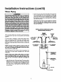
• Look at the top cover of the water heater. The cold water
inlet is markedcold. Put two or three turns of teflon tape
around the threaded end of _e threaded-to-sweat coupling
and around both ends of the ¾ threaded nipple. Using flexible connectors, connect the cold waterpipe to the coldwater
inlet of the waterheater.
AWARNING
HOVrERWATERCAN SCALD:.
Water heatersareintended
to
producehot _
Water heatedto a temperaturewhichwill
satisfy
clotheswashing,
dishwashing,andothersanitizing
needs
_n sealdandpmnanentlyInjureyou uponcontoc_Somepe_
pie m_emore Wadyto be pem_nen_ injured by hot w_er _
others.These I_fude t_ elde_ ddldren, the k_irm,orp_sk_
ly/mentally
handicapped.
If anyoneusinghot waterinyourhome
Etsinto one ofthese gruupsor ifthere is a localcade or stato law
requiringa certaintompeeature _
at the hot watortap,then
foumusttakespecial
precaudom.
Inadditionto usingthelowest
)ossible
ttmperatum set,rigthatsatisEes
yourhotwaterneeds,
_meanssuchasa mixingvalve,should
beusedat thehotwater
tapsusedbythesepeopleor ot the woterheater.Mixingvalves
aruwallableat plumbing
supl_y
or han_r_xestoreLFollowmanufacturersinstructionsfor installationof the valves.Before
changingthe factory settingon the thermostat, read the
"TemperatureRegulation"
section
in thismanual.
NOTE: This water heater is super insulated to minimize
heat loss from the tank. Further reduction in heat loss
can be accomplished by insulating the hot water lines
from the water heater.
INSTALLATION
COMPLETED
USING
SEARS INSTALLATION
KIT
FLEXIBLE
WATER
CONNECTORS
This waterheater shall not be connected to any heating systems
or component(s) used with a non-potable water heating
appliance.
If a water heater is installed in a closed water supply system;
such as one having a back-flow preventer, check valve, water
meter with a check valve,etc.., in the cold water supply; means
shall be provided to control thermal expansion. Contact the
local utility or local Sears Service Center on how to control this
situation.
SHUTOFF
VALVE
HOT OUTLET
COLD INLET
TO HOUSE
WATER
THREADED
314" THREADED
COUPLING
NOTE: Toprotect against untimely corrosion of hot and
cold water fitthags, it is steon_iy recommended that all-electric unions or couplings be mstelled on this water heater
when connected to copperpipe.
SWEAT
TO
_
THREADED
_
_
COUPLING_
LINE
TO
314"THREADED
COUPLING
SWEAT
COUPLING
The illustration shows the attachment of the water piping to the
water heater. The water heater is equipped with 3Ainch water
connections.
_
NOTE: If using copper tubing, solder tubing to an adapter
before auaching the adapter to the cold water inlet connection. Do not solder the cold water supply line directly to the
cold water inlet. It will harm the dip tube and damage the
tank.
TEMPERATUREPRESSURE
RELIEF VALVE
--
DISCHARGE
PIPE (Do not cap
or plug)
[]
• Look at the top cover of the water heater. The water oudet is
markedhot. Put two or three turns of teflon tape around the
threaded end of the threaded-to-sweat coupling a-,xdaround
both ends of the _A"threaded nipple. Using flexible connectors, connect the hot water pipe to the hot water outlet on
the waterheater.
,_
_6"
FLOOR
11
AIR GAP
DRAIN
Installation
Instructions
Temperature-Pressure
(cont'd)
Relief Valve
A WARNING
A, WARNING
At the time of manufacture this water heater was provided
with a comb_nat;_nm_ratu_--,_ures
relief valvecerti_d
by a nationally recognized testing laboratory that maintains
periodicinspectionof productionof listedequipmentor materials, as meeting the requirements for Relief Valves and
Automatic Gas ShutoffDevicesfor Hot Water SupplySystems,
and the latest edition of ANSI Z21.22 and the code requirements of ASME. If replaced,the valve must meat the requirements of localcedes,but not lessthan a combinationtempera.
ture andpressurerelief valvecertified as meeting the _luiremerits for ReliefValvesandAutomatic Gas ShutoffDevicesfor
Hot Water SupplySystems, AHSLZ2|.Z2 by a nationallyrecog.
nized testing laboratory that maintainsperiodic inspectionof
productionof llstedequipment or materials.
The valve must be made:d with a maximum set presserenot
to exceed the marked hydrostatic working pressureof the
water heater (I 50 IbsJsq.in.) and a dischargecapacitynot less
than the water heater input rate as,shownon the model rating
plate. (Electric heaters • watts divided by 1000 x 3415 equal
BTU/I-Ir. rate.)
Yourlocaljurisdictionalauthority,while mandatingtbe useof a
temperature-pressure relief valvecomp,Wying
with ANSI 7.21.22
and ASME, may require a valve model differentfrom the one
fomished with the water heater.
Compliancewith suchlocalrequirements must be satisfiedby
the installeror end userof the water heater with a locallyprescribed temperature-pressure relief valveinstalledin the designatecl openingin the water heater in placeof the factory furnishedvalve.
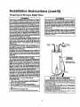
For safeoperationof the water heate_,the relief valvemust not
be mrnovedfrom it'sdesignatedopeningor plugged.
The temperature-pressure reliefvalvemust be installeddirectly
intothe fittingof the water heaterdesignatedfor the relief valve.
Pesltlenthe valvedownwerdandpravidetebing so that anydi_
chargewill exit only within 6 inchesabove,or at any distance
below the structuralfloor. Be certainthat no contactis made
with anyliveelectricalpart. The discha_eopeningmust not be
Mocked or reduced in size underany circumstances.Excessive
length, avev30 fa_€,er useof mere th_ fonr elbewscancause
restriction andreducethe dischargecapecityof the valve.
No valveor other obstructionisto be placedbetweenthe relief
valveand the tank. Do nut connecttubingdirectlyto discharge
drainunlessa 6" air gapisprovided.Topreventbodilyinjury,hazard to life, or propertydamage,the relief valve mustbe allowed
to dischargewater in quantitiesshouldcircumstances
demand.If
the dischargepipeis not connectedto a drain or other suitable
means,the water flowmaycausepropertydamage.
The DischargePipe:
Must not be sm_ller in size than the outiot pipe size of the
valve,or haveany reducingcouplingsor other restrictions.
Mustnot be pluggedor blocked.
Mustbe of material listedfor hot water distribution.
Must be installedso as to allow complete drainageof both
the temperature-pressure
relief valve, and the discharge
pipe.
Must terminate at an adequatedrain.
Mustnot haveany valvebetweenthe relief valveand tank.
The temperature-pressure relief valve must be manually
operated ot least on©ea year, Cantion shoukl be taken to
onsore that (I) no one is in front of or around the oudet of
the temperoture-peessurerefiofvalve dischargeline, and (2)
the water manually discharged will not cause any bodily
injury or property damage because the water may be
extremely hot.
If after manually operating the valve, it fails to completely
reset and continuesto releasewater_immediately dose the
cold water inlet to the water heater, follow the draining
instructions, and replace the temperature-pressure relief
valvewlth a new ane.
-II--HOT
q
SHUTOFF
VALVE
COLD
PRESSURE
REUEF VALVE
PiPE
(Do not cap or plug)
6" AIR GAP
FLOOR
DRAIN
RELIEFVALVEOPENING
At sfiedineof manu_'mre,
thiswaterheaterv_s
edwisha €ombfoedon
tera;_-_u_
rd_ va_e_sted_sconing _'w_ _an_ for _ _
_d
automatic
g)sshut-off
d_ces forhotwatersupply
sy_ems,
ANSI7)1.22.Forsafo
opera_oe
ofshewaterheater,
_be_ief vahemustn_ beremoved
fromitsdesignated
pointofinstaria_on
orplng_l.
relief_ complying
withANSI7.21.22andASMF.
mayrequireavahemodeldiffe_nt
fromtheonefurnished
withthewaterhea_e_
ofC_iancewishsuchlocalrequirements
mustbesatisfied
by_e installer
or enduser
waterheaterwi_haIo_11_
prescribed
ter_erature-pr_sure_ief valve
In.ailed
inthedesignated
opening
inthewa_erbea_.
Seemanualbe_ding
-"Temper_tur_Pressure
ReliefValves"
forinstalb_on
ant;maintenanceofreliefvalve_
discharge
line,andostlersafer/precauri_n_.
12
Installation
Filling the Water
Instructions
(cont'd)
Heater
For proper venting in certain installations,a largerdiametervent
pipe may be necessary. Due to greatvariancesin installations,
unforeseeableby the manufacturer of the water heater, you must
consult your gas company to aid you in determining the proper
venting for your water heater from the venttables in the latest edition of the National Fuel Gas Code ANSI Z223.1, alsoreferredto
asNFPA 54.
ACAUTION
Nev_ usethis water hex/;erunlessit is completelyfilled with ]
water. To pravent damagete the tank, the tank mu_ be filled ]
with water. Water must flow from the hot water faucet
beforetumng 'ON gnsto the water heater,
To fill the water heater with water:
• Close the water heater drain valve by turning the handle to
the right (clockwise). The drain valve is on the lower front of
the water heater.
• Open the cold water supply valve to the water heater.
NOTE: The cold water supply valve must be left open
when the water heater is in use.
• To insure complete filling of the tank, allow air to exit by
opening the nearest hot water faucet. Allow water to run
until a constant flow is obtained. This will let air out of the
water heater and the piping.
• Check all new water piping for leaks. Repairas needed.
Check the ventingsystem for signsof obstructionor deterioration
and replaceif needed.
The combustion and ventilationair flowmustnot be obstructed.
AWARNING
heaithriskor _.
• Place the draf_ hood legs in the receiving holes on the top of
the water heater. The legs will snap in the holes to give a tight
fit.
• Phce the vent pipe over the draft hood. With
1
the vent pipe in
position, drill a small hole through both the vent pipe and
draft hood. Secure them together with a sheet metal screw.
Venting
A WARNING
VENT DAMPERS. Any vent damper, whether it is operated
thermaJlyor otherwisemust be removedif itsuseinhibitsprop.
er drdCingof the water he_er.
Thermally Operated Vent D_rnpers:Gas-firedwater heaters
havingthermal et_ency in excessof 80%may producea rela_vely lowfluegastemperature. Suchtemperaturesmay not be
high enough to properly open thermally operated vent
danll_H,s.Thiswould causesptll_ of flue pses midmay Quse
carbonmonoxidepoisoning.
Ventdampersmust bear evidenceof certificationascomplying
with the latest edition of American National Standard ANSI
7.21.68(ANSI Z21.6_ & 67, respectS, coverelec_;callyand
mechank:al_/ac_
vent dan_).
Boforeim(:all,_ of any
ventdampe_consuityour localSearsServiceCenter or the gas
ORAFTHOOO
41'
IVeNT J
f
SCR_
DRAFT
HOOD
OR
DRAFT
H( OD_VEI_ITNTE_OUTDOORS,,
N
I
AWARNING
The waterhexterwlth drafthoodInstalled
mustbe properlyI
ventedto a chimneywhichterminatesoutdoors.Neveroper-I
atethe_
hext_runless
it isventecl
to the outxJoors
andhas[
adequate
airsupply
te avoidrisksof improperoperation,
explosionor asphyx_on.
AWARNING
To insure proper venting of this gas-fired water heater, the
correct vent pipe d'_-_er must be utilized,Any additionsor
deletlom of other ps applianceson a common vent with this
water heater maqfadverselyofrect the operation of the water
heater.Consultthe localSearsService Center or gas udllty if
anysuchchangesare planned.
AWARNING
I
The _mt pipefrom the water heater must be no lessthan the I
diameter of the draft hood outlet on the water heater, and
_)o_S ope upward to the ch mney at east '/4 nch per near
13
Installation
Venting
Instructions
(cont'd)
Gas Piping
(cont'd)
All vent gases must be completelyvented to the outdoors of the
structure (dwelling). Instal[only the draft hood provided with
the new water heater and no otherdrafthood.
Vent pipes must be secured at each joint with sheet metal screws.
AWARNING
Makesure the gassuppliedis the same type listedon the
modelns_ngpia_ The Inlntgaspressurenmstnnt exceed
10.S in. water column ('].61d_) for natuili
gas or 13 in.
column(3.2kPa)for propane(I.R) gas.The minimuminlet
gaspressurelistedon the modelredng plate isfor the purpose04'inputadjustment.
CHIMNEY
TO
RISE PFEc_NEAR
I
!
AWARNING
If the gescona'olvaiveIssubjectedto pressures
exceeding½]
poundper squareinch(3._la_a),the damageto the gascon-I
tml velvecouklrnsultin a tim or explosion
fromleaidnggel J
VENT PIPE INSTALLATION
There must be a minimum of 6" dearance between single wall
vent pipe and any combustible maserial. Fill and seal any deatance between single wall vent pipe*and combustible material
with mortar mix, cement, or other noncombustible substance.
Forother than singlewall, follow vent pipe manufacturer's dear0axcespecifications.To insure a dgb-t fit of the vent pipe in a
brick chimney, seal around the vent pipe with mortar mix
cement.
AWARNING
] If the maingaslineshutoffservingall gasappliancesis used,]
I also tom "off" the ges et each appliance. Leaveall gas appii- J
I
th"
I
A gas line of su_cient size must be tun to the water heater.
Consult the latest edition of National Fuel Gas Code ANSI
Z223.1, also referredto as NFPA54 and the gascompany concerning pipe size.
AWARNING
Failureto havemqulrecl.,
durances betweenventpipingand
combustible _
will remit Ina Em hazard.
There mustbe:
• A readilyaccessiblemanualshut off valvein the gas supplyline
servingthe water heater,and
• A dripleg (sediment trap)aheadof the gascunt_rolvalveto hdp
prevent dirt and foreign materials from entering the gascontrol
valve.
• A flexible gas connector or a ground joint union between the
shutoff valveand control valveto permit servicingof the unit.
Besureventpipe isproperlyamnoctodto preventnscapeof
AWARNING
]
dangemmIlueSasns
which€ouldcausedead_asphln_o_
Be sure to check all the gas piping for leaks before lighting the
water heater. Use a soapy water solution, not a match or open
flame. Rinse offsoapy solution and wipe dry.
AWARNING
Chemicalvaporcorrosionof the flue and vent systemmay
occurif air for combustion
containscertainchemicalveporL
Spraycan pmpellonts,
deaningsolvents,refrigeratorKtd air
conditionerrefrigerants,swimmingpool chemicals,calcium
andsodiumddoride,waxe_bleach,and process
chemlcals
are
typicalcompounds
whicharepotentially
€orrnslve.
Standard Models are for imtattadon up to 3,300 feet above sea
level.
fl_h Altltud¢ Models are for insm]htion from 3,300 to 5,500
ahove sea levd.
If a standard toodd isinstalled above 3,300 feet or a high altitude
model is installed above 5,500 feet, the input rating must be
reduced at the rate of 4 percent for each 1,000 feet above sea level.
Contact your local Sears Service Center or gas udlity for further
information.
AWARNING
The appliance and its gasconnectionmust be leaktested
befo_p_clagtheafCl_acemoperaUo_
14
Installation
Instructions
(cont'd)
GAS PIPING WITH
FLEXIBLE CONNECTOR
AWARNING
• The q3pliance
rand_ individual
shutoffvalsemasthe disconnectedfromthelas _3ply pipingI_-m duringmr¢prassure
testingof the gassystemat test pressures
in excessof
. peundpersc_relech(3.SkP',).
LOOP
Theapprmsemustbeiselated
fromthe_s supplypipinlsystern bydosingitsindividual
manualshutoffvalveduringany
pressure
tastingofthe gassupplypipingsystemat testprassuresequalor less_ _ poundpersquare
inch(3.5kPa),
I
GROUND
GAS
CONTROL
VALVE
&WARNING
Use pipejoint compoundor teflon tape marked as beingJ
SEDIMENT
CAP
TRAP
GAS PIPING WITH
ALL BLACK
PIPE TO GAS CONTROL
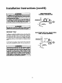
A sediment trap shall be installed as close to the inlet of the
water heater as practical at the time of water heater installation.
The sediment trap shall be either a tee fittingwith a capped nipple in the bottom oudet or other device recognized as an effecfive sediment trap. Ira tee fitting is used, it shall be installed in
conformance with one of the methods of installation shown
below.
Connecting the gas piping to the gas control valve of the water
heater can he accomplishedby either of the two methods shown.
AWARNING
Contaminents
Inthe Ips rmesn_/came i_
oper_on
of the gas€ontrolvalvethat r,_/rasult in tire or expleslen.
Be(oreIttKhleg the gasIlee he surethat angaspipeisdean
on the imlde.To _ap any dirt or foreignmateslalIn the gas
LJCAP
supply line, a drip leg (sometimes called a sediment trap)
must be incocperated in the piping. The drip leg must he
readilyaccessible.Install in accordancewith the "Gas Piping,"
sectine. Refer to the letest ediUon of the National Fuel Gas
Code, ANSI 7.223.1,alse re_-md to as NFPA 54.
15
IRON
Installation
Instructions
Installation
Checklist
BEFORE LIGHTING
THE PILOT:
(cont'd)
• Check the gas lines for leaks.
a. Use a soapy water solution. DO NOT test for gas leaks
using a match or open flame.
b. Brush the soapy water solution on all gaspipes, joints and
fittings.
c. Check for bubbling soap• This means you have a leak.
Turn OFF" gas and make the necessary repairs.
d. Recheck for leaks.
e. Rinse offsoapy solution and wipe dry.
VENT PIPE TO
OUTDOORS
OR CHIMNEY
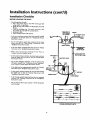
• Is the new temperature-pressurereliefvalveproperly installed
and piped to art adequate d_in? See _Temperatttre-Pressure
ReliefValve"section•
Is the water heater completdy filled with water? See "Filling"
instructions in the Installation Instructions section.
•
Will a water leak damage anything?
Consider About the Location" section.
•
Is there proper clearance between @e water heater and anything that might catch fire? See the Facts to Consider About
the Location" section.
SHUTOFF VALVE
HOT
COLD
• Are the cold and hot water lines connected to the water
heater correctly? See "Water Piping" instructions in the
_lnstallation Instructions _ section.
•
UNION
DRAFT
HOOD
PRESSURE
REUEF VALVE
See the "Facts to
•
Do you have adequate ventilation so that the water heater
will operate propetly? See Combustion Air and Ventilation
in the _Facts to Consider About the Location" section.
•
'"
Is the draft hood vent piping
proper ly secured. See ....Ventmg_
instructions
m the Installation Instructions
section.
(Do
GAS SUPPLY
SHUTOFF
not
rap
or
VALVE
TEE
(Sediment
trap)
•
PIPE CAP
i
6" AIR GAP
Is there proper dearance betw_n the vent pipe and anything
that might catch on fire. See Venting instructions in the
"Installation Instructions" section.
DRAIN
VALVE '
FLOORDRAIN
• Is the vent pipe properly sloped and does the vent terminate
outdoors? See "Venting" instructions in the "Installation
Instruct ons seCtiOn.
• Do you need to call your gascompany to check the gas pipe
and its hookup?
MODEL
16
RATING
PLATE
plug)
Operating
Instructions
Lighting
A WARNING
BEFORE LIGHTING [PROPANE (L.P.) GAS WATER
HEATERS]:Propane(L.R) gasis heavierthan air. Shouldthere
be a leak in the system,the gas will settle near the ground.
Basements,crawl spaces, skirted areas under mobile homes
(evenwhenventilated),closetsandareasbelowgroundlevelwill
serve as pockets for the accumulation of this gas. Before
attemptingto light or relightthe water heater'spilot or turning
on a nearbyelectricallight switch,be absolutelysurethere isno
accumulatedgasin the area.Searchfor odor of gasbysniffingat
groundlevelin the vicinityof the appliance.If odor isdetected
followstepsindicatedat "For YourSafety" on the coverpageof
this manualthen leavethe premises.
Figure 6
Lighting and operating instructions are located on front of the
water heater, above or to one side of the gas control valve.
_,WARNING
AN ODORANT IS ADDED TO THE GAS USED
BY THIS WATER HEATER.
FOR YOUR SAFETY
IF YOU SMELL GAS:
• Do not try to light any appliance.
• DO not touch any electricalswitch;do not useany phone in
your building.
• Immediately callyour gassupplierfrom a neighbor's phone.
Follow the gassuppiier_instruedons.
• If you cannot reach your gas supplier,call the fire depart-
Figure 7
merit.
AWARNING
DO NOT force the ges contrnl Imob. Use only your hand to
pushit down to light the pilot, or to turn it to "ON", "OFF"
or "PILOT". Never use a tool such as a lever,w_nch or pliers. Do not hit or damage the knob. A darnaged Imob may
result in an explosionand suHous injury. If you haveproblem
turning the Imob,callthe gassupplier immediately.
Figure 8
CHECK
FOR LEAKS
Be sure to check all your gas pipes for leaks before lighting your
water heater. Use a soapy water solution, not a match or open
flame. Check the factory gas fittings after pilot is lit and gas control knob is still in "PILOT" position. Then, check the fittings
when the main burner is turned "ON". Use a soapy water solution for this, too.
_INNER
DOOR
OUTER
DOOR
Figure 9
17
Operating
Instructions
Lighting
label on the water
FOR YOUR
SAFETY
heater
(cont'd)
as it appears above the thermostat
READ
BEFORE
LIGHTING
If you do not follow these instructions exactly, a fire or explosion
WARNING
i
may resu t caus ng property damage, personal injury or oss of I re.
A. Thisappliancehas a pilot whichmustbe lightedby
hand.Whenlightingthepilot,followtheseinstructions
exactly.
B. BEFORE
LIGHTING
smellall aroundtheappliance
area
for gas. Be sure to smell next to the floor because
somegasIs heavierthanair andwillsettleonthefloor,
WHATTODOIF YOUSMELLGAS
• Donottry to lightanyappliance.
• DOnot touchany electricswitch;do not use any
phonein yourbuilding.
• Immediately
callyour gassupplierfroma neighbor's
phone,FollowthegassuppJier'sinstructions,
LIGHTING
• If you cannotreachyourgassupplier,callthe fire
department.
C. Useonlyyour handto pushin or tumthe gascontrol
knob.Neverusetools.If theknobwillnot pushin or
turnbyhand,don'ttryto repairit, calla qualifiedservice technician.Forceor attempted
repatrmay result
in a fireorexplosion.
D. Do not usethis applianceif anyparthasbeenunder
water,tmmedictely
ca, a quaitfledservicetechnician
toinspecttheapplianceandto replaceanypart ofthe
controlsystemand anygas controlwhichhasbeen
underwater.
INSTRUCTIONS
1. STOP!Readthesafetyinformation
aboveonthislabel.
2. Remove
outerdoor.
3. Satthe thermostatto lowestsetting,by turning the
watertemperature
dialclockwise,
(( _,)to itslowest
temperature
setting(witharrowondial)as shown.DO
NOT FORCE.
4, Turngascontrolknobclockwise_)
to "OFF"position. Knobcannotbe turnedfrom"PILOT" to "OFF"
unlessknob is depressedslightly.DO NOT FORCE.
(Figure6, page17)
5. Waitfive(5) minutesto clearout anygas.If you than
smellgas, STOP!Follow"B" in the safetyinformation
aboveon this label.If youdon'tsmellgas,go to the
nextstep.
6. Remove(or open)innerdoor located belowthe gas
control unit.
7. Findpilot-follow
metaltubefrom gascontrol.Thepilot
islocatedIn frontoftheburner.
PILOT BURNER
_
I
THERMOCOUPLE
tLX_
8. IfyoUdon'tsmellgas,turnknobongascontrolcounter
clockwlse_,_' to "PILO'F"position.
(Figure7,page17)
g. Push in control knoball the way and hold down.
Immediately
lightthepilotwitha match,Continueto
hold coutmtknobin for aboutone (1) minute alter
the pilotIs lit. Releaseknoband itwill popbackup.
Pilotshouldremainlit. If it goesout,repeatsteps3
through8.
• it knobdoesnotpop upwhenreleased,stopand
immediatelycall yourservicetechnicianor gas
supp,m.
• If the pilot will not stay lit after severaltries,
depR*ssandturnthegascontrolknobclockwise
i(_ _ to "OFF"ahdcallyourservicetechnician
or gassupplier.
(Figure6,page17)
10. Replace(or close)Innerdoor.Replaceouterdoorif
doordoesnotcover gascontrolon/offknobor tamparatureadjustment
knob.(Figure9, page17)
11. Atarmslengthaway,turngascontrolknobcounterclockwise_
tothefull "ON"position.Wanting
do not use gas control knob to regulate gas
flow. (Figure8,page17)
12.At armslengthaway,set thethermostatto desired
setting.Themark( • ) HOTindicative
of approximate
120°Fis preferredstartingpoint.Somelocallaws
may requirea lowerstartingpoint,If hotterwateris
desired,
seeinstruction
manual
and"warning"below.
13.Replace
theouterdoorIf notreplacedin step10.
I Hotterwaterincreasesthe riskof scaldinjury.Beforechanging
WARNING
temperaturesettingsee instructionmanual.
TO TURN
OFF GAS TO APPLIANCE
1. Set thethermostatto lowestsettingbyturningthe
watertemperature
dial clockwise
(F'_) to Its lowest
temperature
setting(witharrowon dial)as shown.DO
2. Turngascontrolknobclockwise_')
to "OFF"
position.Knobcannotbe turnedfrom "PILOT" to
"OFF" unlessknobis depressedslightly.DO NOT
FORCE.
3. Replace
outerdoor(ifremoved).
NOT FORCE,
18
Operating
Temperature
Instructions
(cont'd)
Regulation
Due to the nature of the typical gas water heater, the water tem_oerature in certain situations may vary up to 30°F higher or
wet at the point of use such as, bathtubs, showers, sink, etc.
Turn the water temperature dial clockwise (ff"_)
to decrease
the temperature, or counterclockwise (_",_)
to increase the
temperature.
This means that when the temperature adjustment dial is set at
the mark approximating 120 ° F, the actual water temperature at
any hot water tap could be as high as 150°F or as low as 90°E
Any water heater's intended purpose is to heat water. Hot water
is needed for cleaning (bodies, dishes, clothing). Hot water will
present a scald hazard. Depending on the time element and the
people involved (normaladults,
children, toddlers, elderly,
infirm, etc.) scalding may occur at different temperatures.
AWARNING
HOTTER WATER CAN SCALD: Water heatersare intendedto
prod.
uco hot water. Water heated to a temperature which will
sa'dsfyclotheswashing_dishwashing,and other sanitizingneeds
can scald_nd permanently injure youupon contact.Some people are more likelyto be permanently in uredby hot water than
othem These indudethe elderly,children,the infirm,or physicallylmentallyhandicapped.If anyoneusinghot water in your home
fits into oneofthese groupsor ifthere isa localcodeor statelaw
requiringa certaintemperature water at the hot water tap,then
_m must take specialprecautions.In additionto usingthe lowest
mssibletemperature settingthat satisfiesyourhot water needs,
Lmeanssuchasa mixing valve,shouldbe usedat the hot water
tpps usedbythese people or at the water heater Mi_ingvalves
are availableat plumbingsupplyor hardwarestore_ Followmanufacturers instructions for installation of the valves. Before
changing the factory setting on the thermostat, read the
'q'emperature Regulation"sectionin this manual.
PILOT LIGHTING-Set
here before attempting to light pilot.
• HOT-Is a thermostat setting of approximately
120°F,which will supply hot water at the
most economical temperatures. The
temperature adjustment knob can be
turned lowerthan "HOT" if desired.
A-Is a thermostat setting of approximately
130°E
B-Is a thermostat setting of approximately
140°F. This is the lowest setting for
supply of hot water to dishwashers.
AWARNING
J
Neverallowsmallchildrento usea hot water_ or to draw
thalrownbathwater,Neverleavea childor handicapped
per- I
sonunattendedn a bathtubor shower.
I
C-Is a thermostat
150°E
setting of approximately
VERY HOT-Is a thermostat setting of 160°F. It is
recommended that the dial be set lower
whenever possible.
NOTE: Water temperature range of 120°--140°F
mended by most dishwasher manufacturers.
The thermostat of this water heater has been factory set at its
lowest position, to reduce the risk of scald in ury. It is adjustable
and must be reset to the desired temperature setting. The mark
(•) HOT indicative of approximately 120°F is title preferred
stattin_ point. Some states have a requirement for a lower setting. Iryou need hotter water, follow directions for temperature
adjustment, but beware of the warnings in this section.
recom-
AWARNING
Shouldoverheatingoccuror the gassupplyfail to shutoff,
turn"OFF" the manualgascontrolvalveto the appliance.
19
Service and Adjustment
Tank (Sediment)
Cleaning
Burner
Sediment build-up on the tank bottom may create varying
amounts of noise, and if left in the tank will cause premature
tank failure. In some waterareas, you may not be able to drain
all sediment deposits by simply draining the tank. In these cases
MagErad (part no. 23600) can be used to help remove the sediment deposits. This may be ordered from the Sears Service
Center. Forordering,referto the "Repair Parts"section.
Inspection
AWARNING
I
Do ont usethisapldianceif any pert of it hasbeen ander water. _
Immediately call a Sears Service Technician to inspect the I
appliance and to replace the gas control or any part of the
burner systemwh ch hasbeen underwat_
At least once a year a visual inspection should be made of the
main burner and pilot burner. The drawing is for your reference.
Venting System Inspection
You should check for sooting which is not normal and will
impair proper combustion.
At least once a year a visual inspection should be made of the
venting system. You should look for:
• Obstructions which could cause improper venting. The combustion and ventilation air flow must not be obstructed.
Damage or deterioration which could cause improper venting or leakage of combustion products.
Rusted flakes around top of water }_eater.
&WARNING
Chemical vapor corrosion of the flue and vent system may
,occur if air for combustion contains certain chemicalvapors.
! Spray can propellants, cleaningsolvents,refrigerator and air
conditioner refrigerants, swimming ponl chemica/s, calcium
and sodiumchloride,waxes,bleach,and processchemicalsare
typicaicompoundswh chare potentiallycorrosive.
AWARNING
J
Soot build-up indicates a problem that requires correction
beforefurther use. Turn "OFF" gas to water heater and leaveI
"OFF" until repairs are made, becausefailure to correct the
cause of the sooting can result in a fire or explosioncausing
DEATH, SERIOUS BOD LY NJUI_, OR PROPERTYDAMAGE.
AWARNING
Obstructedor deteriorated ventsystemsmay presenta serious
heaithrisk or usphyxiation.
Burner
AWARNING
In the event your burner
instructions:
[
Be sure the vent piping is properly connected to prevent ]
escape of dangerous flue gosseswhich could cause deadly
needs cleaning,
use the following
If inspection of the burner shows that cleaning is required, turn
the gas control knob dock'wise (ff"x)
to the "OFF" position,
depressing slightly.
asphyxation.
AWARNING
Cleaning
NOTE: The knob cannot be turned from "PILOT" to "OFF"
unless knob is dept-'_,sedslighdy. DO NOT FORCE.
I
If after inspection of the vent system you found sooting or I
deterioration, something iswrong. Call the localgas utility to ]
correct the problem and dean or replace the flueand venting
before resum ng operation of the water heater.
Loose deposits on or around the burner can be removed by carefully using the hose of a vacuum cleaner inserted through the
access door of the water heater. If the burner needs to be removed
fo_ additional cleaning, call the Sears Service Center to remove
and clean the burner and correct the problem that required the
burner to be cleaned.
2O
Service and Adjustment
I-R Gas Control Valve & Burner
Assembly Replacement
Information
(cont'd)
Temperature-Pressure
Valve Operation
Tb_e tcmperatu_-pressu_
at least once a year.
Relief
rdief vatve must be man_ally operated
&WARNING
PROPANE (L.R) GAS CONTROL VALVE AND BURNER
ASSEMBLY REPLACEMENT INFORMATION.
TEMPERATURE-PRESSURE
RELIEF VALVE
/
For Propane (I.R) Gas ModelsOnly:,
Your water heater is equippedwi_ • Propane (I-R) gascontroi valve and a main burner assemblywith left:hand threads
for the followingfittingsand their connections.
•
•
The connecdon between
cont_ v_
(A _o B) are
The connection between
and che manifold (C to D)
the manifold and the gas
left hand threads_
the main burner orifice
are left hand threads.
DISCHARGE
For ordering these replacement parts, please refer to
the "Repair Parts" section ofthi_ manual.
P!PE
Failureto install and maintain a new properly listed temperature-pressure rdief valve will releasethe manufacturerfrom any
claimwhich might resultfrom excessivetemperature or pressure.
AWARNING
If the temperstur_prassererelief valveon the appliance
wanpsec disd_q_s periodicall_this maybe dueto thermai
expansion,Your water heater may have a checkvalve
installedIn the water line or s water meter with a check
valv_ Consultthe SearsSecvicoCenterfor furthecinforma.
don. Do notplugthe temperature-peassure
railervalve.
&WARNING
Whan chedd_ the tempereteretammrer_
Draining
tio_ male mm _at (I) no one is in front of or asound the
outlet of the _anperatemtammre
relief valve disdwlle line,
and(2)_
The water heater should be drainedif being shut down during
freezing temperatures. Also periodic draining and cleaning of
sediment from the tank may be necessary.
•
•
•
•
•
•
I
va_e opera-
thewmr manual/a_harged
wmnot€_.e any
pmper_ dam_e beaue thewaternW beexm._y
hot
If after manually operating the valve, it _ls to completely
reset anci continuesto _qease w'_er, immediate_ dose the
cold water inlet to the water heater, follow the draining
instructions, and replace the temperature-pressure
relief
wive wi_ a ouw one.
Turn the gas control knob to the _OI_F"position.
CLOSE the cold water inlet valveto the water heater.
OPEN a nearby hot water faucet and leave open to allow for
draining.
Connect a hose to the drain valve and terminate to an adequate drain.
OPEN the water heater drain valve to allow for tank
draining.
NOTE: If the water heater is going to be shut down and
drained for an extended period, the dra_ valve should be
left open with hose connected allowing water to terminate
to an adequate drain.
Close the ctrainvalve.
Follow instructions in the "Filling The Water Heater"
section.
Follow the lighting instructionsin the "Lighting" section to
restartthe waterheater.
21
Service and Adjustment
Drain Valve Washer
Replacement
NOTE_ For replacement, use a '_" x "/_" x ½" d,i.'ckwasher
available at your n¢_u-esthardware.to_ For ordmlng _phcemeritwashers,
n&mto thc "l_m O_lc: Li_ section.
•
•
Turn _OFF" gassupply to waterheater.
Follow Draining insu'uctions.
Turning counter clockwise, remove the hex cap below the
screw handle.
Removethe washer and put the new one in place.
Screw the handle and cap assembly back into the drainvalve
and retightenusing a wrench. DO NOT OVER TIGHTEN.
Follow instructions in the "Filling The Water Heater"
section.
Check for leaks.
Follow the lighting instructions in the *Lighting" section to
restartthe water heater.
HANDLE
ASSEMBLY
Housekeeping
Vacuumaround base of water heater for dust, dirt, and lint on a
regularbasis.
AWARNING
INSTALLED IN SUITABLE AREA: To insure sufficient ventilation and combustion air supply, proper
clearances from the water heater must be maintained. See "Facts to Consider About the Location"
section. Combustible materials such as clothing,
cleaning materials, or flammable liquids, etc. must
not be placed against or adjacent to the water
heater which can cause a fire.
Service
Before calling for repair service, read the Start Up Conditions
and Operational Conditions found in the Troubleshooting
Guideof this manna[.
If a condition persists or you are uncertain about the operation
of the water heater, let a qualified person check it out.
Contact SEARS Repair Services at 1-800-4-MY-HOME
(1-800-469-4663).
22
(cont'd)
Troubleshooting
Guide
Start Up Conditions
THERMAL
EXPANSION
HOT
COLD
Water supply systems may, because of such events as high line
pressure, lrequent cut-offs, the effects of water hammer among
others, have installed devices such as pressure reducing valves,
check valves,back flow preventers, etc-.to control these types of
problems. When these devicesare not equipped with an internal
by-pass,and no other measures are taken, the devicescause the
water system to be dosed. As water is heated, it expands (thermal expansion) and closed systems do not allow for the expansion of heated water.
WATERHEATER
COLDWATER
INLETFITTING
÷:,g1
The water within the water heater tank expands as it is heated and
increases the pressure of the water system. If the relieving point of
the water heater's temperature-pressure reiief valve is reached, the
valve will reheve the excess pressure. The tcml_-amrc-preasure
relief valve is not intended for the constant relief of thermal
_pansion.
This is an unacceptable condition and must be corrected.
WA'_R
SHUTOFF
RECOMMENDED
8q_g.LKnO_l
0mmCAL NOUN_)
It is recommended that any devices instal!ed which could create a
closed system have a by-pass and/or the system have an expansion tank to relieve the pressure built by thermal expansion.
Thermal expansion tanks are available from Sears stores and
through the Sears Service Centers. Contact the local plumbing
inspector, water supplier and/or the Sears Service Center for
assistance in controlling these situations.
WATERHEATBR
COLD WATER
INLET FII"nNG
HOT
Thermal
Expansion
COLD
5
Expansion
Expansion
Tank
Capacity
Needed
FLOOR,CEIUNG
JOIS_,ETC.
STRAPPING
Tank Specifications
Model
Tank Capacity I Dimensions in Inches Pipe Fitting
Number
In Gallons
Diameter
Length
On Tank
153.331020
2
8 inches 12_ inches _" Male
153.331050
O)
PRESSURE
REDUCING
YALVE
VVlTH
BY-PA_
PRJESSURE
REDUCING
VALVE WITH
INLET COLD
WATER
SHUTOFF
1l inches 14_inches I _" Male
Tank Sizing Chart
Inlet*
Water
Pressure
40psi
50psi
60psi
70psi
80psi
Water Heater Capacity (Gallons)
30
2
2
2
2
2
40
2
2
2
2
5
50
2
2
5
5
5
66
5
5
5
5
5
ALTERNATERECOMMENDED
IN_'DU.LAT_N
(HORIZONTAL M_NG)
82
5
5
5
5
5
STRANGE
SOUNDS
*Highest recorded inlet water pressure in a 24 hour period or
regulated water pressure.
Possible noises due to expansion and contraction of some metal
parts during periods of heat-up and cool-down do not represent
h_rofuL or dangerous conditions.
NOTE: Expansion tanks are pre-charged with a 40 psi air
charge. If the inlet water pressure is higher than 40 psi, the
expansion tank's air pressure must be adjusted to match that
pressure, but must not be higher than 80 psi.
Condensation causes sizzling and popping with the burner area
during heating and cooling periods and should be considered
normal. See _Condensarion" section.
23
Troubleshooting
Start Up Conditions
Guide
(cont'd)
(cont'd)
CONDENSATION
SMOKEIODOR
Whenever the water heater is filled with cold water, a certain
amount of condensation will form while the burner is on. A
water heater may appear to be leakingwben in fact the water is
condensation. This usually happens when:
• When a new water heater is fdled with cold water for the
first time.
• When gas burns and water vapor is produced in water
heaters, particularly high efficiencymodels where flue temperatures are lower.
• When you use large amounts of hot water in a short time
and the refill water is very cold.
It is not uncommon to experience a small amount of smoke and
odor during the initial start-up. This is due to burningoffof oil
from metal parts, and will disappear in a short while.
Operational
SMELLY
WATER
In each glasslined water heater there is installed at least one
anode rod (see parts section) for corrosion protection of the
tank. Certain water conditions will cause a reactionbetween this
rod and the w_ter.The most common complaint associated with.
the anode rod is one of a "rotten egg smell'. This odor is derived
from hydrogen sulfide gas dissolved in the water. The smell is
the resultof four factors which'must all be present for the odor
to develop:
Moisture from the products of combustion condense on the
cooler tank surfaces and form drops of water which may fall
onto the burner or other hot surfaces to produce a %izzling"or
"fryi_" noise.
Excessive condensation can cause pilot outage due to water running down the flue tube onto the main burner and putting out
the pilot.
a. a concenttation of sulfate in the supply water.
b. little or no dissolved oxygen in the water.
c. a sulfate reducing bacteria within the water heater. (This
harmless bacteria is non-toxic to humans.)
d. an excessof active hydrogen in the tank. This is caused by
the corrosion protective actionof the anode.
Because of the suddenness and amount of water, condensation
water may be diagnosedas a _tank leak". After the water in the
tank warms up (about 1-2 hours), the condition should
disappear.
Smellywater may be eliminated or reduced in some water heater
models by replacingthe anode(s) with one of lessactive material,
and then chlorinating the water heater tank and all ,hot water
lines. Contact Sears Service for further information concerning
an Anode Replacement Kit #9001453 and this Chlorination
Treatment.
Do not assume the water heater is Leaking until there has been
enough time for the water in the tank to warm up.
An undersized water heater will cause more condensation. The
water heater must be sized properly to meet the family's
demandsfor hot water includingdishwashers,washing machines
and showerheads.
Iftbe smelly water pezsists after the anode replacement and chlorination treatment, we can only suggest that continuous chlorination and filtering conditioning equipment be considered to
eliminate the waterproblem.
Excessive condensation may be noticed during the winter and
early spring months when incoming water temperatures are at
their lowest.
Do not remove the anode leaving the tank turl_rotected. By
doing so, all warranty on the water heater tank Is voided,
Good venting is essential for a gas fired water heater to operate
properly as well as to carry away products of combustion and
water vapor.
"AIR"
&WARNING
HOTTER WATER CAN SCALD:. Water heatersare intendedto
IN HOT
WATER
FAUCETS
AWARNING
HYDROGENGAS:Hydrogengascanbe producedin a hot
watersymmlthat hasnot beenusedfor a longperiodoftime
(generallytwo weeksor more). Hydrogengasis extremely
flammableand explosive.
To p_vant the possibility
of injury
undertheseconditions,
we recommendthe hot waterfaucet
be openedfor severalminutesat the kitchenrinkbeforeany
elecUkala_lian_s whichareconnected
to thehatwatersystom are used(suchasa dishwasher
or washingmachine).If
hydrogengasis present, there will probablybe an unusual
soundsimilarto air escaping
throughthe pipe_ the hotwater
faucet is opened. Theremust be no smokingor open flame
nearthefaucetat the timeit isopen.
Im._,.
,..,uce hot water. Water heated to a tomperatore whichwill,
satisfy clotheswashing,dishwashing,and other sanitizingneeds
can scaldand permanentlyinjureyou uponcontact. Some people are more likelyto be permanentiyinjuredbyhot water than
obhergTheseindudethe elderly,children,the infirm, or physically/meotaEyhandicapped.If anyoneusinghot water in yourhome
fits intoone of thesegroupsor If there isa Io¢.alcndeor statelaw
_ring
Conditions
a certeintomperaUa'e water at tbe hot watortap,then
sm must lake specialpmcautiens.In addition to usingthe lowest
KWZi/de
_,_at_e
setting that satisfies _r
bet wzt_- nee_
Lrn_u_ such _ a mfaing valve, should be used at the hot water
taps usedby thesepeople or at the water heater.Mixingvalves
are availableat plumbingsupplyor hardwarestores,Followmanufacturers instructions for installation of the valves. Before
changing the factory setting on the thermostat, read the
"Temperature Regulation"set'denin thismanual,
24
Troubleshooting
HIGH
TEMPERATURE
SHUT
OFF
Guide (cont'd)
SYSTEM
AWARNING
Due to the nature of the typical gaswater heater, the
water temperature in certain situationsmay be hotter
than the thermostatsetting.
Short, frequent drawsof hot water - especiallywith very
coldincomingwater - canshockthe thermostatintobrief
operation resulting in hotter and hot_cerlayersof water
closerto the top ofthe tank.
Changesin.hot water usagepatternsor r_stng the tempereture differential between the cut-onof the thermostat and the coldwater temperaturewill usuallyeliminate
the problem.
This water heater is equipped with an automaticgas shut offsystern. The high temperature shut off is built into the gas control
valve. This system shuts off the gas supply to the water heater
burners when high water temperatures are present. It is nonresertable.If the high temperature shut offactivates,the gascontrol valvemust be replaced.If this were to occur,turn _OFF" the
entire gas supply to the water heater. Contact the Sears Service
Center.
AWARNING
Shouldoverheatingoccuror the gassupplyfail to shutoff,
torn "OFF" the manualgascontrolvalveto the appliance.
NOT
ENOUGH
OR NO HOT
WATER
Check the pilur flame, It may have gone out. All models have
_ Check
the manualgas
offvaFceto
be surethe
it ispilot.
open.
an opening
behind theshut
outerdoor
for viewing
If the pilot is not lit, followthe _Lighting"instructions in this
manual or located above the gas control valve on the water
heater to relight thepilot. If the water was extremelyhot and is
now cold, the high limit safety temperature shut off may have
put out the buraer and pilot, If the hi_ temperature shut off
activates,the gas controlvalve must be rephced.Contact the
SearsServiceCenter.
The temperature adjustmentdial may be set too low. See the
Temperature Regulation section,
gascompany
canmust
checkbethe
gasinput
seeif position.
it is correct.
_i The
The gas
control knob
turned
to theto_ON"
An underfired water heater will not heat water as quickly.
Look for leaking or open hot water faucets. Make su_ all are
dosed.
• The cold water inlet temperature may be colder during the
winter months, It will take longer to heat the water and seem
like lesshot water.
• If you cannot find what is wrong, call the Sears Service
Center.
WATER
IS TOO
HOT
• The temperature adjustment dial may be set too high. See the
Temperature Adjustment section.
NOTE: A period of time is aecessaWafter sunadjmunent
has been made for the water temperature to reach the new
temperature sett_.
• If lower temperature settings will not lower the water temperature, call the Sears Service Center.
25
Troubleshooting
Guide (cont'd)
Leakage Checkpoints
Use this guide to check a "Leaking" water heater. Many suspected _Leakers" are not leaking tanks. Often the source of the water
can he found and corrected.
ACAUTION
I
Read this manualfirst. Then before checkingthe water I
] heater make sure the gas supply has been turned I
"OFF", and never turn the gas"ON" beforethe tank is
I completelyfull of watur.
Ifyou arenotthoroughly
familiar
withyourLocal
gascodesyour
water heater, and safety practices, contact the
Cent_ to check the water heater.
ACAUTION
Never use this water _ter
unless it is completely filled
with water. To prevent damage to the tank, the tank I
must be filled wiganwater. Water must Row from the hot ]
]water faucet before turning "ON" gas to the water]
Water at the draft hood is water vapor which has
condensed out of the combustion products. This is caused
by a problem in the vent. Contact the Sears Service Center
*Condensation
be be
seen
on pipes in humid weather or
pipe connectionsmay
may
leaking.
O'The
primary anode rod fitting may be leaking.
Small amounts ofwater from temperature-pressure relief
valve may be due to thermal expansion or high water
pressure in your area.
*The temperature-pressure
the tank fitting,
relief valve may be leaking at
Water from a drain valve may be due to the valveopened
slightly.
O-The
drainvalve may be leaking at the tank fitting.
Combustion
vapor
can
condense on products
the coolercontain
surfaceswater
of the
tank.which
Droplets
form and drip into the fire or run on the floor. This is
common at the time ofstartup after installation and when
incoming water is cold.
Water
in the water heater
bottom or onorthethefloor
be
from condensation,
loose connections,
reliefmay
valve.
DO NOT replace the water heater until a full inspection
of all possible water sources is made and necessary
corrective steps taken. Leakage from other appliances,
water lines, or ground seepage should also be checked,
®
O
NOTE: To check where threaded portion eaters tank,
insert cotton swab between jacket opening and fitting.
If cotton is wet, follow "Draining"
instructions in the
"Service and Adjustment" section and then remove
fitting. Put pipe dope or teflon tape on the threads
and replace. Then fi_llow "Filling the Water Heater"
instructions in the "Installation Instructions" section.
26
Notes
27
Notes
28
Notes
29
Parts Order
List
POWER MISER TM 9 GAS WATER HEATERS
MODEL NUMBERS:
153.337113
153.337162
153.337213
153.337262
153.337362
153.337413
50
50
40
40
30
40
Gal.
Gal.
Gal.
Gal.
Gal.
Gal.
Short High Altitude
Short
Short High Altitude
Short
High Altitude
18
19
....
2
I
16
17
6t
12
3O
Parts Order
List (cont'd)
POWER MISER TM 9 GAS WATER HEATERS
MODEL NUMBERS:
153.337113
153.337162
153.337213
153.337262
153.337362
153.337413
50
50
40
40
30
40
Gal.
Gal.
Gal.
Gal.
Gal.
Gal.
Short High Altitude
Short
Short High Altitude
Short
High Altitude
Model Numberm
KEY
NO. PARTDESCRIPTION
1
2
Temperature-PressureReliefValve
Primary Anode Rod
3
4
5
6
7
8
Model Ratin_ Platet
Drain Valve
Drain ValveWasher
('_" • '_" x _" chick)**
Thermocouple*
Pilot Tubin6 w/Fittings
Burner Orifice
9
10
Manifold
Pilot
11
12
13
Manifold Cover
Inner Door
Gas Control Valve
14
15
Temperature Adjustment Knob
Burner
16
17
18
Dip Tube
Flue Bail%
Draft Hood
19
#
Restrictor Ring
Manual
#
Mag-Erad
153.337113
153.337162
9000071
9000734
0270118
9000058
9000071
9000734
0270118
9000058
9001584
42-33900
9000278
0230141
#36(HA)
9002619
9000284
9000358
9000281
F145-1278
F145-1280
9002411
9002067
9001584
42-33900
9000278
0230120
#33
9002619
9000284
9000358
9000281
F145-1278
9OO2495
9000273
9001208
F145-1280
9002411
9002067
9002495
9000273
9001208
153.337213
153.337262
PART NUMBERS
9000071
9000071
9001829
9001829
0270118
9000058
0270118
9000058
9001584
9001584
42-33900
9000278
0230141
#36(HA)
9002617
9000284
42-33900
9000278
0230120
#33
9002617
9000284
9000358
9000281
F145-1278
F145-1280
9002411
9001981
9002281
9000273
9000358
9000281
F145-1278
F145-1280
9002411
9001981
9002281
9000273
9000275
9000275
0002915840
23600
153.337362
153.337413
9000071
9000734
0270118
9000071
9000734
0270118
9000058
9000058
9001584
42-33900
9000278
9001584
42-33900
9000278
0230120
#33
9002613
9000284
9000358
9000281
F145-1278
0230141
#36(HA)
9002615
9000284
9000358
9000281
F145-1278
F145-1280
9002411
9001698
F145-1280
9002411
9OO2490
9000273
9000275
9001698
9000516
9000273
9000275
Now thatyou have purchased your Gas Water Heater, shoulda need ever exist for repairparts or service,simplycontact any SEARS Service
Center orcall 1-800.4-MY-HOME (1-800-469-4663). Be sure to providepertinent factswhen you call or visit.
All parts listedmay be orderedfrom any SEARSServiceCenter, mostSEARSstores and by calling 1-800-366-PART(1-800-366-7247). If the
partsyou need are not stockedlocally,your orderwill be electronicallytransmitted to a SEARSRepairPartsDistribution Center for handling.
The model number of your Gas Water Heaterwill be found on the model rating plate located near the gas control valve.
WHEN ORDERING REPAIRPARTS,ALWAYSGIVE THE FOLLOWING INFORMATION:
MODEL NUMBER
PARTDESCRIPTION
PARTNUMBER
NAME OF ITEM
THIS IS A REPAIRPARTSLIST,NOT A PACKINGLIST.
31
Parts Order
POWER
MISER
MODEL
NUMBERS:
TM
List (cont'd)
9 GAS WATER
153.337462
40 Gal.
153.337513
153.337562
153.337613
50 Gal. High
50 Gal.
65 Gal. High
HEATERS
Altitude
Altitude
[
I
I
I
I
16
|
17
0
14Q
%
12
32
Parts Order
List (cont'd)
POWER MISER TM 9 GAS WATER HEATERS
MODEL NUMBERS:
153.337462
4O Gal.
153.337513
50 Gal. High Altitude
153.337562
50 Gal.
153.337613
65 Gal. High Altitude
Model Numbers
IKEY
NO.
153.337462
153.337513
9000071
9000734
9000071
9000734
0270118
9000058
9000071
9000734
0270118
9000058
9000071
9000734
0270118
9000058
9001584
42-33900
9001584
42-33900
9001584
42-33900
0230120
#33
9002615
9000284
9000278
0230141
#36(HA)
9002617
9000284
9000278
0230120
#33
9002617
9000284
9000278
0230141
#36(HA)
9002619
9000284
9000358
9000281
F145-1278
F145-1280
9002411
9001698
9000516
9000273
9000275
9000358
9000281
F145-1278
F145-1280
9002411
9001698
9000298
9000273
9000275
9000358
9000281
F145-1278
F145-1280
9002411
9001698
9002496
9000273
9000275
9000358
9000281
F145-1278
F145-1280
9002411
9001982
9000419
PART DESCRIPTION
153.337562
153.337613
PARTNUMBERS
1
2
Temperature-Pressure
Primary Anode Rod
Relief Valve
3
4
5
Model Ratin_ Plate t
Drain Valve
Drain Valve Washer
("k" • '_" x ¼" thick)**
6
7
8
Thermocouple*
PiLot Tubing w/Fittings
Burner Orifice
9
10
Manifold
Pilot
11
12
13
Manifold Cover
Inner Door
Gas Control Valve
14
15
Temperature Adjustment Knob
Burner
16
17
18
Dip Tube
Flue Baffle
Draft Hood
19
#
Resrrictor Ring
Manual
#
Mag-Erad
0270118
9000058
9001584
42-33900
9000278
9000273
9000275
0 002915840
23600
Now that you have purchased your Gas Water Heater, should a need ever exist for repair parts or service, simply contact any SEARS Service
Center or call 1-800-4-MY-HOME (1-800-469-4663). Be sure to provide pertinent facts when you call or visit.
All parts listed may be ordered from any SEARS Service Center, most SEARS stores and by calling 1-800-366-PART (1-800-366-7247). If the
parts you need are not stocked locally, your order will be electronically transmitted to a SEARS Repair Parts Distribution Center for handling.
The model number of your Gas Water Heater will be found on the model rating plate located near the gas control valve.
WHEN
ORDERING REPAIR PARTS, ALWAYS GIVE THE FOLLOWING INFORMATION:
MODEL NUMBER
PART DESCRIPTION
PART NUMBER
NAME OF ITEM
THIS IS A REPAIR PARTS LIST, NOT A PACKING LIST.
33
Parts Order
List (cont'd)
POWER MISER TM 9 GAS WATER HEATERS
MODEL NUMBERS:
153.337662
65 Gal.
153.337762
50 Gal. Higfi Recovery
153.337862
65 Gal. Higtt Recovery
153.337960
40 Gal. (L.P.)
16
17
0
34
Parts Order
List (cont'd)
POWER MISER TM 9 GAS WATER HEATERS
MODEL NUMBERS:
153.337662
65 Gal.
153.337762
50 Gal. High Recovery
153.337862
65 Gal. High Recovery
153.337960
40 Gal. (L.P.)
Modal
153.337662
KEY
NO.
Temperature-Pressure Relief Valve
Primary Anode Rod
3
4
Model Radng Plate t
Drain Valve
5
Drain Valve Washer
(_" x %" • W' d,.i&) **
6
7
8
Note _A':
PART DESCRIPTION
1
2
9
10
11
12
13
Thermocouple*
Pilot Tubin_ w/Fittings
Burner Orifice
(Drill Size)
Manifold
Pilot
Manifold Cover
Inner Door
Gas Control Valve
14
15
Temperature Adjustment
Burner
16
17
18
Dip Tube
Flue Baffle
Draft Hood
19
Restrictor Ring
#
Manual
#
Mag-Erad
9000071
9000734
0270118
9000058
9001584
42-33900
9000278
Knob
0230120
#33
9002619
9000284
9000358
9000281
F145-1278
F145-1280
9002411
9001982
9000419
9000273
9000275
153.337762
Numbers
153.337862
PART NUMBERS
9000071
9000071
9000734
0270118
9000058
9000734
0270118
9000058
9001584
42-33900
9000278
0230124
#30
9002617
9000284
9001584
42-33900
9000278
0230124
#30
9002619
9000284
9000358
9000281
F145-1278
F145-1280
9002411
9001698
9000371
9000358
9000281
F145-1278
F145-1280
9002411
9001982
9000299
9000274
9000274
9000297
9000297
0002915840
23600
153.337960
9000071
9000734
0270118
9000058
9001584
42-33900
9000278
0230223
#49
9002616
9000286
9000358
9000281
F145-1279
F145-1280
9002651
9001698
9000516
9000273
9000275
For Propane (L.E) model(s) this part has left hand threads.
* These parts are also available at most Sears retail stores.
** Also available at most hardware stores.
tReplaced only on return of damaged plate.
# Not Illustrated
Now that you have purchased your Gas Water Heater, should a need ever exist for repair parts or service, simply contact any SEARS Service
Center or call 1-800-4-MY-HOME (1-800-469-4663). Be sure to provide pertinent facts when you call or visit.
All parts listed may be ordered from any SEARS Service Center, most SEARS stores and by calling 1-800-366-PART (1-800-366-7247). Iftbe
parts you need are not stocked locally, your order will be electronically transmitted to a SEARS Repair Parts Distribution Center for handling.
The model number of your Gas Water Heater will be found on the model rating plate located near the gas control valve.
WHEN
ORDERING REPAIR PARTS, ALWAYS GIVE THE FOLLOWING
MODEL NUMBER
PART DESCRIPTION
PART NUMBER
NAME OF ITEM
THIS IS A REPAIR PARTS LIST, NOT A PACKING LIST.
35
INFORMATION:
Warranty
About YourWarranty
a.Adjustingthermostat.
b.Lightingpilot.
c. Leaksinpipesorfittings.
d. Improperventing
e. Condensation
THE PRICEOF YOURWATERHEATERDOES NOT INCLUDE
A FREECHECKUP SERVICECALL.On Water HeaterInstallations
ArrangedBySea_,Searswarrantsthe installation.
ON INSTALLATIONSNOT MADE BYSEARSAUTHORIZED
CONTRACTORS:
I. YourSearswarrantyappliesto the productonly.
2. Searsdoesnot warrantthe installation.
3. A charge will be madeon servicecallsdue to poor or incomplete
installation.Theseindude:
This manual is in non-technicallanguage.It mayhelp youavoid the
cost of a needlessservicecall. Manyservicecallsreallyarent needed.
Suchaswhen:
1. Thegasis turned "OFF".
2. Thepilotis out.
3. A gasorwaterleakisdue to loosepipeorconnections.
FULLONE YEARWARRANTYON WATERHEATER
For one year from the dateof purchase, when your Sears Kenmore waterheateris installedand operatedin a single-family nmidencein
accordance with the instructions in this manual,Searswill:
1. Repairdefectsin material orworkmanship in this water heater, freeof charge,
2. Furmshand mstall a new current model waterheater of equal capacity and quality, free of charge, if a leakoccursin the tank.
LIMITED WARRANTYON TANKSTHAT LEAK
After one year and through 9 years from the date of purchase forwater heaters used in a single-familyresidence,ifa leakoccursin the
tank, Seamwill furnish a new curtent model water heater of equal capacity and quality. Youwill be charged for any installation.
LIMITED
WARRANTY
ON PARTS
After one year and through 9 years from the date of purchase, when your SearsKenmote water heater isused in a single-family n:sidence
and isinstalled and operatedin accordance with the information in this manual, if a part fails due to a materialsor workmanship, Sears
will furnish a rephcement free of charge. Youwill be charged for labor.
If the water heater is subjected to commercial, institutional,industrial or use in residencesof two families or mote, the abovewarranty
coverage for tanks that leak is effective for 2 years from the date of purchase and the aboveparts warranty iseffectivefor 1 year from the
date of purchase.
To obtain warranty service, SIMPLYCALL1-800-4MY-HOME (1-800-469-4663). "Thiswarranty appliesonly while this product is in
use in the United States._
This warranty giv_ you specific legal tights and you may also have otherrights which varyfrom state to state.
SEARS, ROEBUCK AND CO,, Dept. 817 WA, HOFFMAN
Sears Installation
Warranty
In addition to any warrantyextended to you on the Sears merchandise
involved, which warrantybecomes effective the date the merchandiseis
installed should the workmanship of any Sears arranged installation
prove faulty within one year, Sears will, upon notice from you, cause
such faults to be corrected at no additional cost to you. If you want this
heater professionally installed by Sears contact your Sears Salesperson.
They will arrangefor prompt, quality installation.
ESTATES, IL 60179
Sears Installation
Policy
All instalhtion labor arrangedby Searsshall be performedin a neat,
workmanlikemannerin accordance
with generallyacceptedtrade practices. Further,all installationsshall complywith all locallaws,codes
reguhtionsandordinances.
The customershall alsobeprotected,during installation,by insurancerelatingto propertydamage,Workers
Compensationand PublicLiability.
If you want this water heater professionallyinstalledby Searscontact
yourSalesperson.Theywill arrangefor prompt,qualityinstallation
by
Searsauthorizedcontractors.
ForIn-home
majorbrandrepairservice
Call24 hours
a day,7 daysaweek
1-800-4-MY-HOME
(t.em-4ee4ees)
The modelnumberof yourwaterheaterisfoundonthe modelratingplateon thefrontof the waterh_ater.
Sears, Roebuck and Co., Hoffman
Estates, IL 60179 U.S.A.
02, su 0