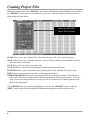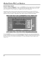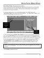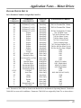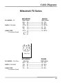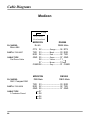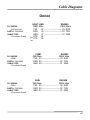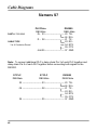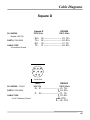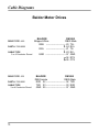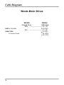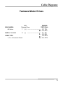
1
DN-3000
AN INTELLIGENT
MULTIPLE-FUNCTION COMMUNICATIONS
INTERFACE UNIT FOR DEVICENET
User Manual
ICP PANEL-TEC
Post Office Box 2394
Huntsville, Alabama 35804
(205) 534-8132
Warranty & Notices
WARRANTY
ICP PANEL-TEC, INC. warrants that all equipment purchased hereunder is warranted on a “RETURN
TO FACTORY” basis against all defects in workmanship and materials under normal and proper use and
service in its unmodified condition for a period of one (1) year from the date of initial shipment. ICP
PANEL-TEC, INC. sole obligation under this warranty shall be limited to furnishing parts and labor to
remedy such defects; either, at the option of ICP PANEL-TEC, INC., by replacing or repairing any
defective parts which are returned to ICP PANEL-TEC, INC. factory or by making available at a
purchaser designated facility a repaired or replaced part. All replaced equipment shall become the
property of ICP PANEL-TEC, INC. The cost of freight to and from ICP PANEL-TEC, INC. will be
borne by the purchaser. If ICP PANEL-TEC, INC. determines that the equipment returned to it for
warranty correction is not defective, as herein defined, Purchaser shall pay ICP PANEL-TEC, INC., all
costs of service, parts, handling and transportation.
IMPORTANT NOTICES
By accepting and using the DN-3000 (s) CONFIGURATION EDITOR SOFTWARE and information
proprietary to ICP PANEL-TEC, INC. USA and/or its Licensers, you agree that such software and
information (Software) constitutes valuable trade secrets and proprietary information of ICP PANELTEC, INC. and/or its Licenses and that you hold the software in confidence and secrecy and shall not, in
whole or part, copy or disclose to any third party or make any unauthorized use thereof. Authorized use
shall be limited to the DN-3000 (s) upon which the Software is initially supplied. You further agree that
this agreement shall insure to the benefit of ICP PANEL-TEC, INC. and any third party holding any
right, title, or interest in the software, or any software and information from which it is derived, and their
respective transferees, successors, and assigns, and that any subsequent transferee of the unit herein
decried shall be obligated to the same terms of this agreement.
This document is based on information available at the time of its publication. While efforts have been
made to render accuracy to its content, the information contained herein does not purport to cover all
details or variations in hardware or software, nor to provide for every possible contingency in connection
with installation, operation, and maintenance.
Features may be decried herein which are not present in all hardware and software systems. ICP
PANEL-TEC, INC. assumes no obligation of notice to holders of this document with respect to changes
subsequently made.
ICP PANEL-TEC, INC. makes no representation or warranty expressed, implied, or statutory, with
respect to, and assumes no responsibility for accuracy, completeness, sufficiency or usefulness of the
information contained herein.
In no event shall ICP PANEL-TEC, INC. be responsible or liable for indirect or consequential damages
that may result from installation or use of this equipment.
(C) 1997 ICP PANEL-TEC, INC.
ALL RIGHTS RESERVED
Post Office Box 2394
Huntsville, Al. 35804-2394
i
Table of Contents
Introduction . . . . . . . . . . . . . . . . . . . . . . . . . . . . . . . . . . . . . . . . . . . . . . . . . . . . . . . . . . 1
Software Installation . . . . . . . . . . . . . . . . . . . . . . . . . . . . . . . . . . . . . . . . . . . . . . . . . . . 2
Software Start-Up . . . . . . . . . . . . . . . . . . . . . . . . . . . . . . . . . . . . . . . . . . . . . . . . . . . . . 3
Creating Project Files
............................................. 4
Project Types . . . . . . . . . . . . . . . . . . . . . . . . . . . . . . . . . . . . . . . . . . . . . . . . . . . . . 5
DeviceNet to PLCs or Devices . . . . . . . . . . . . . . . . . . . . . . . . . . . . . . . . . . . . . . . . . . . 7
Device Profile . . . . . . . . . . . . . . . . . . . . . . . . . . . . . . . . . . . . . . . . . . . . . . . . . . . . 7
Example Applications . . . . . . . . . . . . . . . . . . . . . . . . . . . . . . . . . . . . . . . . . . . . . . 8
Configuring Port #1 (DeviceNet) . . . . . . . . . . . . . . . . . . . . . . . . . . . . . . . . . . . . . 10
Configuring Port #2 (PLCs or Devices) . . . . . . . . . . . . . . . . . . . . . . . . . . . . . . . . 12
Configuring Port #3 (Passthrough) . . . . . . . . . . . . . . . . . . . . . . . . . . . . . . . . . . . . 14
I/O Data Configuration . . . . . . . . . . . . . . . . . . . . . . . . . . . . . . . . . . . . . . . . . . . . . 15
DeviceNet to Motor Drives . . . . . . . . . . . . . . . . . . . . . . . . . . . . . . . . . . . . . . . . . . . . . . 23
Device Profile . . . . . . . . . . . . . . . . . . . . . . . . . . . . . . . . . . . . . . . . . . . . . . . . . . . . 23
Example Applications . . . . . . . . . . . . . . . . . . . . . . . . . . . . . . . . . . . . . . . . . . . . . . 24
Configuring Port #1 (DeviceNet) . . . . . . . . . . . . . . . . . . . . . . . . . . . . . . . . . . . . . . 26
Configuring Port #2 (Motor Drives) . . . . . . . . . . . . . . . . . . . . . . . . . . . . . . . . . . . 28
I/O Data Configuration . . . . . . . . . . . . . . . . . . . . . . . . . . . . . . . . . . . . . . . . . . . . . 30
Upper Link Configuration (Mitsubishi Drives Only) . . . . . . . . . . . . . . . . . . . . . . 38
Exception Table (Mitsubishi Drives Only) . . . . . . . . . . . . . . . . . . . . . . . . . . . . . . 39
Transferring Project Files . . . . . . . . . . . . . . . . . . . . . . . . . . . . . . . . . . . . . . . . . . . . . . 40
Options Settings
Setting the Project Directory . . . . . . . . . . . . . . . . . . . . . . . . . . . . . . . . . . . . . . . . . 42
Selecting the Communications Port . . . . . . . . . . . . . . . . . . . . . . . . . . . . . . . . . . . 44
Setting the Printer Options . . . . . . . . . . . . . . . . . . . . . . . . . . . . . . . . . . . . . . . . . . 45
Load Options . . . . . . . . . . . . . . . . . . . . . . . . . . . . . . . . . . . . . . . . . . . . . . . . . . . . 45
Save Options . . . . . . . . . . . . . . . . . . . . . . . . . . . . . . . . . . . . . . . . . . . . . . . . . . . . . 45
Default Options . . . . . . . . . . . . . . . . . . . . . . . . . . . . . . . . . . . . . . . . . . . . . . . . . . . 45
Technical Information
Power Requirements . . . . . . . . . . . . . . . . . . . . . . . . . . . . . . . . . . . . . . . . . . . . . . . 46
Dimensions . . . . . . . . . . . . . . . . . . . . . . . . . . . . . . . . . . . . . . . . . . . . . . . . . . . . . . 46
DIP Switch Settings . . . . . . . . . . . . . . . . . . . . . . . . . . . . . . . . . . . . . . . . . . . . . . . . 47
LED Indicators . . . . . . . . . . . . . . . . . . . . . . . . . . . . . . . . . . . . . . . . . . . . . . . . . . . 47
Troubleshooting . . . . . . . . . . . . . . . . . . . . . . . . . . . . . . . . . . . . . . . . . . . . . . . . . . 48
ii
Table of Contents
Application Notes – PLCs and Devices
Allen Bradley PLCs . . . . . . . . . . . . . . . . . . . . . . . . . . . . . . . . . . . . . . . . . . . . . . . 49
GE Fanuc PLCs . . . . . . . . . . . . . . . . . . . . . . . . . . . . . . . . . . . . . . . . . . . . . . . . . . 49
Idec PLCs . . . . . . . . . . . . . . . . . . . . . . . . . . . . . . . . . . . . . . . . . . . . . . . . . . . . . . . 50
Koyo (PLC Direct and TI) PLCs . . . . . . . . . . . . . . . . . . . . . . . . . . . . . . . . . . . . . . 51
Mitsubishi PLCs . . . . . . . . . . . . . . . . . . . . . . . . . . . . . . . . . . . . . . . . . . . . . . . . . . 53
Modicon PLCs (and Modbus Devices) . . . . . . . . . . . . . . . . . . . . . . . . . . . . . . . . 53
Omron PLCs . . . . . . . . . . . . . . . . . . . . . . . . . . . . . . . . . . . . . . . . . . . . . . . . . . . . . 53
Siemens S7-200 PLCs . . . . . . . . . . . . . . . . . . . . . . . . . . . . . . . . . . . . . . . . . . . . . . 54
Square D PLCs . . . . . . . . . . . . . . . . . . . . . . . . . . . . . . . . . . . . . . . . . . . . . . . . . . . 55
TI505 Series PLCs . . . . . . . . . . . . . . . . . . . . . . . . . . . . . . . . . . . . . . . . . . . . . . . . 55
Toshiba PLCs . . . . . . . . . . . . . . . . . . . . . . . . . . . . . . . . . . . . . . . . . . . . . . . . . . . . 56
Westinghouse PLCs . . . . . . . . . . . . . . . . . . . . . . . . . . . . . . . . . . . . . . . . . . . . . . . 56
Application Notes – Motor Drives
Baldor Motor Drives . . . . . . . . . . . . . . . . . . . . . . . . . . . . . . . . . . . . . . . . . . . . . . . 57
Mitsubishi Motor Drives . . . . . . . . . . . . . . . . . . . . . . . . . . . . . . . . . . . . . . . . . . . . 59
Woods Motor Drives . . . . . . . . . . . . . . . . . . . . . . . . . . . . . . . . . . . . . . . . . . . . . . . 59
Yaskawa Motor Drives . . . . . . . . . . . . . . . . . . . . . . . . . . . . . . . . . . . . . . . . . . . . . 59
Cable Diagrams
Configuration Cable Diagram . . . . . . . . . . . . . . . . . . . . . . . . . . . . . . . . . . . . . . . . 60
PLC and Device Cable Diagrams . . . . . . . . . . . . . . . . . . . . . . . . . . . . . . . . . . . . . 61
Motor Drive Cable Diagrams . . . . . . . . . . . . . . . . . . . . . . . . . . . . . . . . . . . . . . . . 72
DeviceNet Cable Diagram . . . . . . . . . . . . . . . . . . . . . . . . . . . . . . . . . . . . . . . . . . 76
iii
Introduction
INTRODUCTION
The DN-3000 is an intelligent, multiple-function DeviceNet Data Transfer Unit designed for use within
the harsh industrial environment.
Using the DN-3000 Configuration Editor Software program, the DN-3000 can be programmed to run
either of the two (2) following application types:
1) DEVICENET TO PLCS OR DEVICES Allows a DeviceNet Host to read or write data registers in
one or more PLCs or Devices that use the same protocol. One of the DN-3000’s three ports can be
used as a pass-through port in which all messages received are simply passed through to one of the
connected PLCs/Devices (if supported for that PLC/Device protocol), allowing PLC programming
software, a third party’s intelligent (MMI) Man-Machine Interface terminal or a SCADA software
program to be “connected” to the same port on the PLCs/Devices used by the DN-3000.
2) DEVICENET TO MOTOR DRIVES Allows a DeviceNet Host to control and/or monitor parameters
in up to 32 Motor Drives.
This manual is presented in two sections. Each section deals with the configuration requirements for each
of the above applications: DeviceNet to PLCs and DeviceNet to Motor Drives.
Please note that the application type is selected when a new project is created using the DN-3000
configuration software and may not be changed after the project is created.
1
Software Installation
GENERAL INFORMATION
The Panel-Tec DN3000 Configuration Editor Software Program is designed to operate on an IBM or
compatible computer running MS-DOS 3.3 or higher.
While the Configuration Editor Software Program will run under “WINDOWS 3.1” in most
configurations, it is not recommended. As of this date, no problems have been reported running the
software under “WINDOWS 95”.
The configuration editor software will default during start-up to using “COMM 1” unless changed using
the OPTIONS menu. This may conflict with a mouse driver program and prevent up/down loading
configuration information to the DN-3000 interface unit.
INSTALLATION
Place the supplied program disk into drive “A” (or B).
At the MS-DOS prompt, C:> type in A: (or B:) and then press the “ENTER” key.
When the “A” (or B) prompt appears, A:> type in “INSTALL” and press the “ENTER” key.
The following message will appear;
DN3000 Configuration Editor Installation Program
Enter the drive where the editor is to be installed ==>
Enter “C” (or any other hard drive you care to use), then press the “ENTER” key.
A new message will appear:
Enter the sub-directory on drive C to install the editor into ==>
Suggested directory name is: DN3000
The next message to appear before the installation is started is:
The Editor will be installed from “A” to “C:\DN3000”
Is this correct (Y/N) ?
If the above information is correct, push the “Y” key, then the “ENTER” key and the software will be
installed. The last message to appear will be:
Installation Complete.
Enter “DN3000” to run the configuration Editor
C:\DN3000>
2
Software Information
SOFTWARE START-UP
To start the DN-3000 Configuration Editor program. First start your computer and at the MS-DOS
prompt; C:> type in “CD\DN3000” (to change the directory) then press the ENTER key. At the next
MS-DOS prompt; C:\DN3000>, type in “DN3000” and press the ENTER key to start the
Configuration Editor Software Program.
Upon starting of the configuration software program, the first screen to appear will be the “Support
Information Page”, shown below.
After pressing the computer’s ENTER key, the support information page will disappear. Use the
computer’s LEFT/RIGHT arrow keys and move the highlighted bar (very top of the screen) between the
four (4) main system selection headers. To select any one of these main selection headers, place the
highlight bar around that desired heading and then press the computer’s ENTER key. Below is a brief
description of the main project header and each internal subheading; NOTE: These brief descriptions
listed are as the system starts without any projects opened or new projects created.
Selecting PROJECT opens a menu with the following options:
OPEN allows you to open any saved project file.
NEW allows you to create a new project file.
DOS SHELL allows you to exit to MS-DOS without closing the DN-3000 Configuration Editor
Program and return to the Configuration Editor Program by typing in EXIT and then pressing the
ENTER key.
QUIT allows you to exit the Configuration Editor Program.
3
Creating Project Files
CREATING A PROJECT FILE
To create a project file, move the highlighted bar to the “PROJECT” heading and press the computer’s
ENTER key. When the menu appears move the highlight bar to the “NEW” sub-heading and press
“PROJECT”
Menu
the computer’s ENTER key. At the “Project Name” entry area, type in your file name.
Enter your
Project’s
File Name
After entering in the project’s file name, press the ENTER key. The highlighted bar now moves to
“Project Type”. Press ENTER to open the “Project Type” window (default setting is “DeviceNet to
PLCs or Devices”). Move the highlight bar by pressing the DOWN arrow key to the project type you
wish to configure and then press the ENTER key. The software enters this selection and returns to the
“PROJECT” menu.
4
Creating Project Files
“PROJECT
TYPE”
List
PROJECT TYPES
DeviceNet to PLCs or Devices allows a DeviceNet Host to read and write registers in up to 32
PLCs or devices.
DeviceNet to Motor Drives allows a DeviceNet Host to control and/or monitor up to 32 supported
Motor Drives.
5
Creating Project Files
When the system returns to the “PROJECT’ menu, notice the additional sub-headings that were added to
the “PROJECT” menu and are now available for you to use. A brief description of each of these new
sub-headings are listed below:
Additional PROJECT
Menu Sub-Headings
CLOSE allows you to close a project file. More than one project file can be open at any time.
VIEW allows you to view; the project file name, project file type, and the current selections for each
of the DN-3000’s serial ports.
SAVE allows you to save the current project file.
SAVE AS allows to save the current open project file under a different file name.
SWITCH TO allows you to switch between the opened project files. (Multiple files can be open.)
PRINT allows you to print the project file’s configuration information.
GENERATE EDS FILE allows you to generate an EDS file for the current Project. The EDS file is
used to tell a DeviceNet configuration tool information about the DN-3000 and I/O sizes. If you are
using a DeviceNet configuration tool to set up your DeviceNet network, you should generate a new
EDS file for each project.
Use the RIGHT arrow key to move the highlight bar from the top “PROJECT” header to the top
“EDIT” header to proceed with editing the configuration information stored in the project file.
6
DeviceNet to PLCs or Devices
DEVICENET TO PLCS OR DEVICES
The ”DeviceNet to Motor Drives” application allows a DeviceNet Host device to access data registers in
up to 32 serial PLCs or Devices via Explicit Messages and/or I/O Data.
Explicit Messages allows the DeviceNet Host to issue requests to the DN-3000 to read or write specific
PLC/Device data registers. The DN-3000 converts those requests into serial communications requests in
the selected serial PLC’s or Device’s protocol.
I/O Data allows the DN-3000 to exchange a fixed set of PLC/Device data registers between a DeviceNet
Host and serial PLCs or Devices. The DN-3000 writes Output Data received from the DeviceNet Host to
fixed PLC/Device data registers (see Output Data Table in this section) in the connected serial PLCs or
Devices. Input Data is read from fixed PLC/Device data registers in the connected serial PLCs or
Devices and sent to the DeviceNet Host (see Input Data Table in this section).
Important Note: The DN-3000 can be used to access only data registers in the selected PLCs or
Devices. See the Application Notes for the selected PLC/Device for more information.
DEVICE PROFILE
The DN-3000 is based on the “PLC/Device Gateway” Device Profile, a vendor-specific extension of the
“Communications Adapter” Device Profile (described in the “ODVA DeviceNet Specifications”). This
Device Profile introduces two new vendor-specific Objects: the “PLC/Device Interface Object” and the
“PLC/Device Command Object”. Documentation on this profile and these objects are available from
Panel-Tec, Inc.
The DN-3000 is a Group 2 Only Server utilizing the Predifined Master/Slave Connection Set (as
described in the (ODVA DeviceNet Specifications”). It supports both Explicit Messaging and Polled,
Change-of-State (COS) and Cyclic I/O connections to a DeviceNet Host. It does not support Bit-Strobed
I/O connections.
To access register data via Explicit Messaging, the DeviceNet Host must issue an explicit Get_Member or
Set_Member request to the desired “PLC/Device Interface Object” Instance (based on PLC/Device
Address) of the DN-3000.
If Polled, COS and/or Cyclic I/O connections are to be used, you must first set up the I/O
configuration of the DN-3000 with the DN3000 Configuration Editor software. See I/O Data
Configuration in this section.
7
DeviceNet to PLCs or Devices
EXAMPLE APPLICATIONS
DeviceNet Host to Serial PLC with Pass-Through Connection
Supported PLC or Device
Programming
Software
(if supported)
2
3
DN-3000
DeviceNet Host
DeviceNet Host to Multi-Dropped Serial PLCs
PLC # 1
PLC # 2
RS-422/485
Multi-Drop
Network
2
DeviceNet Host
3
DN-3000
PLC # 3
PLC # 4
PLC # 5
PLC # 6
PLC # 7
Up to 32
PLCs
may be
connected
NOTE: Multiple PLCs/Devices can be connected to Port 2 of a DN-3000 if:
1) All PLCs/Devices use the same protocol.
2) Each PLC/Device can be internally addressed with a network address.
3) Each PLC/Device can communicate on a RS-485/422 multi-drop communications network;
-OR- RS232 to RS485 converters (1 per PLC or Device) are used;
-OR- a 3rd Party multi-port communications expansion module (Port Expander) is used.
8
DeviceNet to PLCs or Devices
Multiple DN-3000s with Different PLC or Device Types
DeviceNet Host
2
3
DN-3000
#1
PLC # 1
Brand A
PLC # 2
Brand A
2
3
DN-3000
#2
PLC # 1
Brand S
2
3
DN-3000
#3
PLC # 1
Brand O
2
3
DN-3000
#4
PLC # 1
Brand M
PLC # 2
Brand O
RS-422/485 Multiple-Drop Networks
2
3
DN-3000
#5
PLC # 1
Brand I
PLC # 2
Brand I
PLC # 3
Brand I
NOTE:
1) Each DN-3000 can support up to 32 PLCs/Devices (if they are network addressable internally).
2) The DeviceNet Host can address a maximum of 63 DN-3000 units.
3) Multiple Brands of PLCs or Devices may be addressed by the DeviceNet Host by using multiple
DN-3000s, but only one PLC/Device Protocol may be used on a single DN-3000 unit.
4) If multiple DN-3000s are to be used, each DN-3000 must be configured with a unique node
address (MAC ID) on the DeviceNet network.
9
DeviceNet to PLCs or Devices
CONFIGURING PORT #1, (DEVICENET)
With the highlight bar around the “PROJECT” header use the RIGHT arrow key and move the highlight
bar to the “EDIT” header This action will close the “PROJECT” menu and open the “EDIT” menu.
DeviceNet to
PLCs or Devices
EDIT Menu
Move the highlight bar to the “Port 1 (DeviceNet)” sub-heading and press the ENTER key to open the
DeviceNet configuration screen.
10
DeviceNet to PLCs or Devices
MAC ID of DN3000
The MAC ID of the DN-3000 is its node address on a DeviceNet Network. The MAC ID of a DN-3000
can range from 0 to 63. Type the desired value in the field and press ENTER.
Baud Rate
Baud Rate determines the rate at which the DN-3000 exchanges data on a DeviceNet network. The Baud
Rate setting must be the same for all devices on the DeviceNet network. The DN-3000 supports baud
rates of 125, 250 and 500 kbps. The dot between the brackets indicates the current selection. Use the
UP/DOWN arrow keys and the SPACEBAR to select the desired baud rate.
11
DeviceNet to PLCs or Devices
CONFIGURING PORT #2 (PLCS OR DEVICES)
When the highlight bar is around the “Port 2 (PLCs/Devices)” sub-heading, press the ENTER key. This
opens a window which allows you to select the type of PLCs or devices connected to this port and check
all of the communication settings.
PORT # 2
PLC
Configuration
Window
PLC/Device Protocol
The window for PORT # 2 Configuration will open with the highlighted bar at the “PLC/DEVICE
PROTOCOL” selection heading. If the displayed Protocol is not the one wanted, simply press the
ENTER key and a smaller window will appear.
PLC/Device
Protocol
Selection
Window
12
DeviceNet to PLCs or Devices
Use your computer’s UP/DOWN arrow keys to move through the PLC/Device Protocol List. Place the
highlight bar on the desired Protocol and press the ENTER key. The software will enter this selection
and automatically close the Protocol selection window. After the selection window closes, you will need
to check the communications setting for the selected Protocol, making changes as necessary.
2 Wire RS422 or RS485 Communications
This box will only need to be checked if the communications with your PLC/Device is a 2-wire RS485 or
RS422 interface. When 2-wire communications are being used, RTS must be looped back to CTS on the
DN-3000 side of the cable. This can be done on the RS232 side by looping pins 4 and 5 or on the
RS422/485 side by looping 16 to 18 and 17 to 19.
DN3000 Address
Some PLC/Device protocols require each PLC or Device on a network to be assigned a unique address.
The DN3000 Address is the address assigned to the DN-3000 on the PLC/Device network.
Communications Settings
The communications settings are automatically set to the default values for each type of PLC/Device
when its Protocol is first selected. Before changing any of these settings, consult your PLC/Device
manual for the correct settings. To move between the communications settings, press the TAB or
ENTER keys. To select a setting, use the UP/DOWN arrow key to move to the desired setting and press
the SPACE BAR to enter or change your selection.
RTS Control (Request to Send Control)
RTS Control selection is an option provided for modems or for PLCs/Devices that require RTS to be
active only while the DN-3000 is transmitting to the PLC. If RTS/CTS is selected, the DN-3000 will
activate RTS and wait until CTS is active before transmitting to the PLC. If RTS Delay is selected, the
DN-3000 will activate RTS and wait for the specified delay time to pass before transmitting to the PLC.
Response Time-Out
The Response Time-Out tells the DN-3000 how long to wait after transmitting a request to a PLC/Device
if no response has been received from the PLC/Device. After this amount of time (specified in
milliseconds) passes with no response being received, the DN-3000 will assume that no response is
coming and will retry the request.
To save the configuration for Port #1, press the “Alt+S” keys or the F10 function key once and a small
window appears stating the information was saved. Press the ENTER key, then the ESC key to return to
the “EDIT” window.
13
DeviceNet to PLCs or Devices
CONFIGURING PORT # 3 (PASSTHROUGH)
Not all PLC/Device protocols allow for the pass-through communications. If your selected Protocol on
Port 2 is capable of pass-through communications, the “Port 3 (Passthrough)” header within the “EDIT”
menu will be black (if light gray, the PLC does not support Pass-Through communications). Place the
Highlight bar around the “Port 3 (Passthrough)” header and press the ENTER key to open this screen.
(See drawing below)
A Selected PLC or
Device Protocol
that supports
Pass-Through
Communications
For descriptions of all entry fields on this screen except for the Intermessage Time-Out, refer to
CONFIGURING PORT #2 (PLCs or Devices) in this section.
Intermessage Time-Out
The DN-3000 uses the Intermessage Time-Out to determine when a complete message has been received
on the PassThrough port. Once the first character of a message has been received, if the amount of time
specified by the Intermessage Time-Out passes with no additional characters being received, the DN-3000
will consider the message to be complete and process it.
Check over the communications settings, making corrections as needed, and save this information by
pressing the letter “S” or the F10 function key(s) once. A small window will appear stating the
information was saved. Press the ENTER key, then the ESC key to return to the “EDIT” menu.
14
DeviceNet to PLCs or Devices
I/O DATA CONFIGURATION
Using the DOWN arrow key, move the highlight bar to the “I/O Data Configuration” sub-heading
within the “EDIT” menu and press the ENTER key. This action opens the I/O Data Configuration setup
screen to allow you to set up the I/O data parameters for your project. You should have some idea of how
you want your I/O set up before selecting this option.
Use I/O Data
If your project requires the use one or more I/O connections (Polled, Change-Of-State (COS) or Cyclic
I/O) for data exchange between the DN-3000 and a DeviceNet host, you should select this option by
pressing the SPACEBAR, ‘X’ or ‘Y’ key on your keyboard. When you select “Use I/O Data”, the other
available I/O options will appear on the screen.
15
DeviceNet to PLCs or Devices
The DN-3000 supports up to a total of 64 bytes (32 words) of combined Input and Output data. Each
word (2 bytes) of Input or Output data can be configured to exchange data with any one valid data register
in any one of the PLCs/Devices connected to port 2 of the DN-3000 (see “CONFIGURING PORT 2” for
PLC/Device Protocol and communication parameters).
Use Command Block
In some projects it may be necessary to be able to access more than just the 32 PLC/Device registers that
can be configured in the Input and Output data. A Command Block reserves the first 4 words of Output
data for commands, and the first 4 words of Input data for command results. This reduces your total
number of words that can be used for register data to 24 words, but adds flexibility by allowing your
DeviceNet Host to issue commands to the DN-3000 to access any valid data registers in any PLC or
Device connected to port 2 of the DN-3000. Commands are issued by moving a command code,
PLC/Device address, file number (Allen-Bradley PLCs only), register number, and data into the first 4
words of the Output data (see “COMMAND BLOCK”).
Use Diagnostics
Diagnostics allows the DeviceNet Host to monitor PLC/Device connections to the DN-3000. The first
word of the Input data following the Command Result Block (if any) will be reserved for Diagnostics if
this option is selected. The DN-3000 keeps track of the connection status with each PLC/Device address
(0-255). Whenever an attempt to communicate with a PLC/Device is successful, the connection status for
that PLC/Device is set to ‘0’. Whenever an attempt to communicate with a PLC/Device is unsuccessful,
the connection status for that PLC/Device is set to ‘1’. Of course, returning 256 status bits would require
16 words of Input data (half of the available I/O data). Instead, only 16 bits (1 word) of are returned.
Each of the 16 bits of the Diagnostics word represents the status of 16 PLC/Device addresses, as follows:
bit 0 represents PLC/Device addresses 0, 16, 32, 48, 64, etc.; bit 1 represents PLC/Device addresses 1, 17,
33, 49, 65, etc.; and so forth. If the status of any of the PLC/Device addresses represented by a bit is ‘1’,
that bit will contain a ‘1’, otherwise, that bit will contain a ‘0’. Note that the status of a PLC/Device is set
to ‘1’ only if the DN-3000 attempts to communicate with that PLC/Device and that attempt is
unsuccessful.
Output Data Size
This determines the number of words of Output data that will be used in your project. Output data is data
that is output from your DeviceNet Host to the DN-3000 (commands, and register data to be written to
PLCs/Devices). This is also known as the Consumed I/O Data of the DN-3000. If a Command Block is
used, it will automatically reserve 4 words of Output data. The combined size of the Input and Output
data must not exceed 32 words.
Output Data
Pressing the Output Data button brings up a window allowing you to edit the configuration of the Output
data in your project. You can press the Output Data button by clicking on it with your mouse, or moving
the focus to the button with the arrow keys and pressing the SPACEBAR. See “OUTPUT DATA
TABLE”.
16
DeviceNet to PLCs or Devices
Input Data Size
This determines the number of words of Input data that will be used in your project. Input data is data
that is input to your DeviceNet Host from the DN-3000 (command results, diagnostics information, and
register data read from PLCs/Devices). This is also known as the Produced I/O Data of the DN-3000. If
a Command Block is used, it will automatically reserve 4 words of Input data for command results.
Similarly, if Diagnostics is used, it will automatically reserve 1 word of Input data. The combined size of
Input and Output data must not exceed 32 words.
Input Data
Pressing the Input Data button brings up a window allowing you to edit the configuration of the Input
data in your project. You can press the Input Data button by clicking on it with your mouse, or moving
the focus to the button with the arrow keys and pressing the SPACEBAR. See “INPUT DATA TABLE”.
17
DeviceNet to PLCs or Devices
OUTPUT DATA TABLE
Within the “I/O Data Configuration” screen, use the DOWN arrow key to move the focus to the Output
Data button and press the ENTER key. This action opens the Output Data Table setup screen to allow
you to set up the PLC/Device registers to be mapped to each word of Output data.
Output data is data received by the DN-3000 from the DeviceNet Host to be written to PLC/Device
registers. Each word of Output data (except those reserved for the Command Block) can be mapped to
specific PLC/Device registers. Output data is only written to registers when that data changes.
Use the UP/DOWN arrow keys to scroll through the list of Output data words until the highlight bar is
over the Output word you wish to edit, and press ENTER. A window will open allowing you to edit the
PLC/Device Address, File Number (Allen-Bradley PLCs only) and Register Number mapped to that
Output word.
18
DeviceNet to PLCs or Devices
Use Output Word xx
If you want to map this word of Output data to a PLC/Device register, select this option. If this option is
not selected, any data appearing in this Output word will be ignored.
PLC/Device Address
This is the Address of the PLC/Device mapped to this word of Output data. The PLC/Device Address
must be in the range 0 to 255.
File Number (Allen-Bradley PLCs only)
This is the File Number of the register in the PLC mapped to this word of Output data.
Register Number
This is the Register Number of the PLC/Device mapped to this word of Output data. Whenever the value
in this Output word changes, the DN-3000 will write that value to the register specified by the
PLC/Device Address, File Number and Register Number.
19
DeviceNet to PLCs or Devices
INPUT DATA TABLE
Within the “I/O Data Configuration” screen, use the DOWN arrow key to move the focus to the Input
Data button and press the ENTER key. This action opens the Input Data Table setup screen to allow you
to set up the PLC/Device registers to be mapped to each word of Input data.
Input data is data read from PLC/Device registers and sent from the DN-3000 to the DeviceNet Host.
Each word of Input data (except those reserved for the Command Block and Diagnostics) can be mapped
to specific PLC/Device registers. Mapped registers in the Input Data Table are read from the
PLCs/Devices and placed in the Input data in a round-robin fashion as quickly as the serial
communications link allows.
Use the UP/DOWN arrow keys to scroll through the list of Input data words until the highlight bar is over
the Input word you wish to edit, and press ENTER. A window will open allowing you to edit the
PLC/Device Address, File Number (Allen-Bradley PLCs only) and Register Number mapped to that Input
word.
20
DeviceNet to PLCs or Devices
Use Input Word xx
If you want to map this word of Input data to a PLC/Device register, select this option. If this option is
not selected, the data in this Input word will be set to 0.
PLC/DeviceAddress
This is the Address of the PLC/Device mapped to this word of Input data. The PLC/Device Address must
be in the range 0 to 255.
File Number (Allen-Bradley PLCs only)
This is the File Number of the register in the PLC mapped to this word of Input data.
Register Number
This is the Register Number in the PLC/Device mapped to this word of Input data. The DN-3000 will
read the value of the register specified by the PLC/Device Address, File Number (Allen-Bradley PLCs
only) and Register Number and place that value in this word of the Input data.
21
DeviceNet to PLCs or Devices
COMMAND BLOCK
Using I/O data to update and/or monitor motor drive parameters requires very little programming in your
DeviceNet Host device – the configuration of the DN-3000 specifies which PLC/Device registers are
mapped to which words of I/O data. However, you can only access a total of 32 registers this way, and
those registers are fixed when the DN-3000 is configured. If your application requires that you access
more than 32 registers, you must either use multiple DN-3000s, or use a Command Block.
A Command Block allows your DeviceNet Host to issue commands at run-time to read or write any valid
register in any PLC/Device connected to Port 2 of the DN-3000. The Command Block reserves the first 4
words of Output data for commands issued by the Host, and the first 4 words of Input data for the results
of those commands (along with any returned data). Commands are issued by moving a PLC/Device
Address, File Number, Register Number, any required Register Data (for write commands only), and a
Command code into the Command Block, as follows:
15
word 1
word 2
word 3
word 4
14 13 12 11 10
9
PLC/Device Address (0-255)
8
7
6
5
4
0
0
0
0
File Number
Register Number
Register Data (write command only)
3
2
1
Command
0
The DN-3000 looks for changes in the Command Block data to determine when there is a new request to
be processed, “throwing out” any invalid commands received. Valid Commands are 1 (read) and 2
(write). To ensure that partial commands are not processed (in systems where it is possible that Output
data could be sent by the host before all 4 words of data have been moved into the command block), you
should set the Command to 0 (indicating no command), then place the data in words 2-4, and only set the
Command to 1 or 2 after all of the other data is in place. After a command has been processed by the DN3000, it will “echo” the command in the Command Result Block in the Input data, and set the Result Code
and any Returned Register Data, as follows:
15
14
word 1
word 2
word 3
word 4
13 12 11 10
PLC/Device Address
9
8
7
6
5
4
1
Result Code
File Number
Register Number
Returned Register Data (read command only)
3
2
1
Command
0
If a read command (1) was issued, the Returned Register Data will contain the register data read from the
specified PLC/Device. If a write command (2) was issued, the Returned Register Data will be the same
as for the issued command. The Result Code indicates the result of processing the issued command.
Valid Result Codes are as follows:
Result Code
0
1
7
22
Meaning
Command was completed successfully.
DN-3000 could not communicate with indicated PLC/Device.
Command was invalid.
DeviceNet to Motor Drives
DEVICENET TO MOTOR DRIVES
The ”DeviceNet to Motor Drives” application allows a DeviceNet Host device to access parameters in up
to 32 serial Motor Drives via Explicit Messages and/or I/O Data.
Explicit Messages allows the DeviceNet Host to issue requests to the DN-3000 to read or write specific
Motor Drive parameters. The DN-3000 converts those requests into serial communications requests in
the selected serial Motor Drive’s protocol.
I/O Data allows the DN-3000 to exchange a fixed set of Motor Drive parameters between a DeviceNet
Host and serial Motor Drives. The DN-3000 writes Output Data received from the DeviceNet Host to
fixed Motor Drive parameters (see Output Data Table in this section) in the connected serial Motor
Drives. Input Data is read from fixed Motor Drive parameters in the connected serial Motor Drives and
sent to the DeviceNet Host (see Input Data Table in this section).
DEVICE PROFILE
This application of the DN-3000 is based on the “Motor Drive Gateway” Device Profile, a vendorspecific extension of the “Communications Adapter” Device Profile (described in the “ODVA
DeviceNet Specifications”). This Device Profile introduces two new vendor-specific Objects: the
“Motor Drive Interface Object” and the “Motor Drive Command Object”. Documentation on this
profile and these objects are available from Panel-Tec, Inc.
The DN-3000 is a Group 2 Only Server utilizing the Predifined Master/Slave Connection Set (as
described in the (ODVA DeviceNet Specifications”). It supports both Explicit Messaging and Polled,
Change-of-State (COS) and Cyclic I/O connections to a DeviceNet Host. It does not support Bit-Strobed
I/O connections.
To access Motor Drive Parameter data via Explicit Messaging, the DeviceNet Host must issue an explicit
Get_Member or Set_Member request to the desired “Motor Drive Interface Object” Instance (based on
Motor Drive Address) of the DN-3000.
If Polled, COS and/or Cyclic I/O connections are to be used, you must first set up the I/O
configuration of the DN-3000 with the DN3000 Configuration Editor software. See I/O
Configuration in this section.
23
DeviceNet to Motor Drives
EXAMPLE APPLICATIONS
DeviceNet Host to Serial Motor Drive
Supported
Motor Drive
DeviceNet Host
2
3
DN-3000
DeviceNet Host to Multi-Dropped Serial Motor Drives
Drive #1
Drive # 2
RS-422/485
Multi-Drop
Network
2
DeviceNet Host
3
DN-3000
Drive # 3
Drive # 4
Drive # 5
Drive # 6
Drive # 7
Up to 32
Drives
may be
connected
NOTE: Multiple Motor Drives can be connected to Port 2 of a DN-3000 if:
1) All Motor Drives use the same protocol.
2) Each Motor Drive can be internally addressed with a network address.
3) Each Motor Drive can communicate on a RS-485/422 multi-drop communications network;
-OR- RS232 to RS485 converters (1 per Motor Drive) are used;
-OR- a 3rd Party multi-port communications expansion module (Port Expander) is used.
24
DeviceNet to Motor Drives
Multiple DN-3000s with Different Motor Drive Types
DeviceNet Host
2
3
DN-3000
#1
Drive # 1
Brand A
Drive # 2
Brand A
2
3
DN-3000
#2
Drive # 1
Brand S
2
3
DN-3000
#3
2
3
DN-3000
#4
Drive # 1
Brand O
Drive # 2
Brand O
RS-422/485 Multiple-Drop Networks
Drive # 1
Brand M
2
3
DN-3000
#5
Drive # 1
Brand I
Drive # 2
Brand I
Drive # 3
Brand I
NOTE:
1) Each DN-3000 can support up to 32 Motor Drives (if they are network addressable internally).
2) The DeviceNet Host can address a maximum of 63 DN-3000 units.
3) Multiple Brands of Motor Drives may be addressed by the DeviceNet Host by using multiple
DN-3000s, but only one Motor Drive Type may be used on a single DN-3000 unit.
4) If multiple DN-3000s are to be used, each DN-3000 must be configured with a unique node
address (MAC ID) on the DeviceNet network.
25
DeviceNet to Motor Drives
CONFIGURING PORT #1, (DEVICENET)
With the highlight bar around the “PROJECT” header use the RIGHT arrow key and move the highlight
bar to the “EDIT” header This action will close the “PROJECT” menu and open the “EDIT” menu.
DeviceNet to
Motor Drives
EDIT Menu
Move the highlight bar to the “Port 1 (DeviceNet)” sub-heading and press the ENTER key to open the
DeviceNet configuration screen.
26
DeviceNet to Motor Drives
MAC ID of DN3000
The MAC ID of the DN-3000 is its node address on a DeviceNet Network. The MAC ID of a DN-3000
can range from 0 to 63. Type the desired value in the field and press ENTER.
Baud Rate
Baud Rate determines the rate at which the DN-3000 exchanges data on a DeviceNet network. The Baud
Rate setting must be the same for all devices on the DeviceNet network. The DN-3000 supports baud
rates of 125, 250 and 500 kbps. The dot between the brackets indicates the current selection. Use the
UP/DOWN arrow keys and the SPACEBAR to select the desired baud rate.
27
DeviceNet to Motor Drives
CONFIGURING PORT # 2 (MOTOR DRIVES)
Using the DOWN arrow key, move the highlight bar to the “Port 2 (Motor Drives)” sub-heading (within
the “EDIT” menu) and press the ENTER key. This action opens the Motor Drive selection screen to
allow you to select the drive manufacturer and to check all the motor drive’s communications settings.
Motor Drive Type
The Port 2 (Motor Drives) Configuration screen will open with the highlight bar at the “MOTOR DRIVE
TYPE” selection area. Simply press the ENTER key to open the current list of supported motor drives.
Use your UP/DOWN arrow keys to move through the drive list and place the highlight bar around the
drive of your choice, then press the ENTER key to enter your selection. The software automatically
saves your entry and closes the “MOTOR DRIVE SELECTION” window.
Motor Drive
Selection
Window
28
DeviceNet to Motor Drives
2-Wire RS422 or RS485 Communications
This box will only need to be checked if the communications with your Motor Drive is a 2-wire RS485 or
RS422 interface. When 2-wire communications are being used, RTS must be looped back to CTS on the
DN-3000 side of the cable. This can be done on the RS232 side by looping pins 4 and 5 or on the
RS422/485 side by looping 16 to 18 and 17 to 19.
Communications Settings
The communications settings are automatically set to the default values for each type of Motor Drive
when the Motor Drive is first selected. Before changing any of these settings, consult your drive manual
for the correct settings. To move between the communications settings, press the TAB or ENTER keys.
To select a setting, use the UP/DOWN arrow keys to move to the desired setting and press the SPACE
BAR to enter or change your selection.
RTS Control (Request to Send Control)
RTS Control selection is an option provided for modems or for Motor Drives that require RTS to be
active only while the DN-3000 is transmitting to the drive. If RTS/CTS is selected, the DN-3000 will
activate RTS and wait until CTS is active before transmitting to the drive. If RTS Delay is selected, the
DN-3000 will activate RTS and wait for the specified delay time to pass before transmitting to the drive.
Response Time-Out
The Response Time-Out is tells the DN-3000 how long to wait after transmitting a request to the Motor
Drive if no response has been received from the drive. After this amount of time (specified in
milliseconds) passes with no response being received, the DN-3000 will assume that no response is
coming and will retry the request.
Minimum Delay Between Messages
The Minimum Delay Between Messages is only needed for Motor Drives that get “confused” when
consecutive requests are sent too close together. The Mitsubishi Z200 Series of Motor Drives is the only
currently known drive that requires this delay (set to 60 ms for Mitsubishi Z200 drives).
Save this information by pressing the Alt+S” or F10 function keys. After the “Information Saved”
window appears, press the ENTER key, then the ESC key to return to the “EDIT” window.
29
DeviceNet to Motor Drives
I/O DATA CONFIGURATION
Using the DOWN arrow key, move the highlight bar to the “I/O Data Configuration” sub-heading
within the “EDIT” menu and press the ENTER key. This action opens the I/O Data Configuration setup
screen to allow you to set up the I/O data parameters for your project. You should have some idea of how
you want your I/O set up before selecting this option.
Use I/O Data
If your project requires the use of Polled, Change-Of-State (COS) or Cyclic I/O to be exchanged between
the DN-3000 and a DeviceNet host, you should select this option.
30
DeviceNet to Motor Drives
The DN-3000 supports up to a total of 64 bytes (32 words) of combined Input and Output data. Each
word (2 bytes) of Input or Output data can be configured to exchange data with any one valid parameter
in any one of the motor drives connected to port 2 of the DN-3000 (see “CONFIGURING PORT 2” for
motor drive type and communication parameters).
Use Command Block
In some projects it may be necessary to be able to access more than just the 32 motor drive parameters
that can be configured in the Input and Output data. A Command Block reserves the first 3 words of
Output data for commands, and the first 3 words of Input data for command results. This reduces your
total number of words that can be used for parameter data to 26 words, but adds flexibility by allowing
your DeviceNet Host to issue commands to the DN-3000 to access any valid parameter in any motor drive
connected to port 2 of the DN-3000. Commands are issued by moving a command code, motor drive
address, parameter number, and data into the first 3 words of the Output data (see “COMMAND
BLOCK”).
Use Diagnostics
Diagnostics allows the DeviceNet Host to monitor motor drive connections to the DN-3000. The first
word of the Input data following the Command Result Block (if any) will be reserved for Diagnostics if
this option is selected. The DN-3000 keeps track of the connection status with each motor drive address
(0-255). Whenever an attempt to communicate with a motor drive address is successful, the connection
status for that address is set to ‘0’. Whenever an attempt to communicate with a motor drive address is
unsuccessful, the connection status for that address is set to ‘1’. Of course, returning 256 status bits
would require 16 words of Input data (half of the available I/O data). Instead, only 16 bits (1 word) of are
returned. Each of the 16 bits of the Diagnostics word represents the status of 16 motor drive addresses, as
follows: bit 0 represents motor drive addresses 0, 16, 32, 48, 64, etc.; bit 1 represents motor drive
addresses 1, 17, 33, 49, 65, etc.; and so forth. If the status of any of the motor drive addresses represented
by a bit is ‘1’, that bit will contain a ‘1’, otherwise, that bit will contain a ‘0’. Note that the status of a
motor drive address is set to ‘1’ only if the DN-3000 attempts to communicate with that motor drive
address and that attempt is unsuccessful.
Output Data Size
This determines the number of words of Output data that will be used in your project. Output data is data
that is output from your DeviceNet Host to the DN-3000 (commands, and parameter data to be written to
motor drives). This is also known as the Consumed I/O Data of the DN-3000. If a Command Block is
used, it will automatically reserve 3 words of Output data. The combined size of the Input and Output
data must not exceed 32 words.
Output Data
Pressing the Output Data button brings up a window allowing you to edit the configuration of the Output
data in your project. You can press the Output Data button by clicking on it with your mouse, or moving
the focus to the button with the arrow keys and pressing the SPACEBAR. See “OUTPUT DATA
TABLE CONFIGURATION”.
31
DeviceNet to Motor Drives
Input Data Size
This determines the number of words of Input data that will be used in your project. Input data is data
that is input to your DeviceNet Host from the DN-3000 (command results, diagnostics information, and
parameter data read from motor drives). This is also known as the Produced I/O Data of the DN-3000. If
a Command Block is used, it will automatically reserve 3 words of Input data for command results.
Similarly, if Diagnostics is used, it will automatically reserve 1 word of Input data. The combined size of
Input and Output data must not exceed 32 words.
Input Data
Pressing the Input Data button brings up a window allowing you to edit the configuration of the Input
data in your project. You can press the Input Data button by clicking on it with your mouse, or moving
the focus to the button with the arrow keys and pressing the SPACEBAR. See “INPUT DATA TABLE
CONFIGURATION”.
32
DeviceNet to Motor Drives
OUTPUT DATA TABLE
Within the “I/O Data Configuration” screen, use the DOWN arrow key to move the focus to the Output
Data button and press the ENTER key. This action opens the Output Data Table setup screen to allow
you to set up the motor drive parameters to be mapped to each word of Output data.
Output data is data received by the DN-3000 from the DeviceNet Host to be written to motor drive
parameters. Each word of Output data (except those reserved for the Command Block) can be mapped to
specific motor drive parameters. Output data is only written to motor drive parameters when that data
changes.
Use the UP/DOWN arrow keys to scroll through the list of Output data words until the highlight bar is
over the Output word you wish to edit, and press ENTER. A window will open allowing you to edit the
Motor Drive Address and Parameter Number mapped to that Output word.
33
DeviceNet to Motor Drives
Use Output Word xx
If you want to map this word of Output data to a motor drive parameter, select this option. If this option
is not selected, any data appearing in this Output word will be ignored.
Motor Drive Address
This is the Address of the Motor Drive mapped to this word of Output data. The Motor Drive Address
must be in the range 0 to 255.
Parameter Number
This is the Parameter Number of the Motor Drive mapped to this word of Output data. Whenever the
value in this Output word changes, the DN-3000 will write that value to the motor drive parameter
specified by the Motor Drive Address and Parameter Number.
34
DeviceNet to Motor Drives
INPUT DATA TABLE
Within the “I/O Data Configuration” screen, use the DOWN arrow key to move the focus to the Input
Data button and press the ENTER key. This action opens the Input Data Table setup screen to allow you
to set up the motor drive parameters to be mapped to each word of Input data.
Input data is data read from motor drive parameters and sent from the DN-3000 to the DeviceNet Host.
Each word of Input data (except those reserved for the Command Block and Diagnostics) can be mapped
to specific motor drive parameters. Mapped motor drive parameters in the Input Data Table are read from
the motor drives and placed in the Input data in a round-robin fashion as quickly as the motor drives’
serial communications link allows.
Use the UP/DOWN arrow keys to scroll through the list of Input data words until the highlight bar is over
the Input word you wish to edit, and press ENTER. A window will open allowing you to edit the Motor
Drive Address and Parameter Number mapped to that Input word.
35
DeviceNet to Motor Drives
Use Input Word xx
If you want to map this word of Input data to a motor drive parameter, select this option. If this option is
not selected, the data in this Input word will be set to 0.
Motor Drive Address
This is the Address of the Motor Drive mapped to this word of Input data. The Motor Drive Address
must be in the range 0 to 255.
Parameter Number
This is the Parameter Number of the Motor Drive mapped to this word of Input data. The DN-3000 will
read the value of the motor drive parameter specified by the Motor Drive Address and Parameter Number
and place that value in this word of the Input data.
36
DeviceNet to Motor Drives
COMMAND BLOCK
Using I/O data to update and/or monitor motor drive parameters requires very little programming in your
DeviceNet Host device – the configuration of the DN-3000 specifies which motor drive parameters are
mapped to which words of I/O data. However, you can only access a total of 32 motor drive parameters
this way, and those parameters are fixed when the DN-3000 is configured. If your application requires
that you access more than 32 motor drive parameters, you must either use multiple DN-3000s, or use a
Command Block.
A Command Block allows your DeviceNet Host to issue commands at run-time to read or write any valid
parameter of any motor drive connected to Port 2 of the DN-3000. The Command Block reserves the first
3 words of Output data for commands issued by the Host, and the first 3 words of Input data for the
results of those commands (along with any returned data). Commands are issued by moving a Motor
Drive Address, Parameter Number, any required Parameter Data (for write commands only), and a
Command code into the Command Block, as follows:
15
word 1
word 2
word 3
14 13 12 11 10
9
8
7
6
5
4
Motor Drive Address (0-255)
0
0
0
0
Parameter Number
Parameter Data (write command only)
3
2
1
Command
0
The DN-3000 looks for changes in the Command Block data to determine when there is a new request to
be processed, “throwing out” any invalid commands received. Valid Commands are 1 (read) and 2
(write). To ensure that partial commands are not processed (in systems where it is possible that Output
data could be sent by the host before all 4 words of data have been moved into the command block), you
should set the Command to 0 (indicating no command), then place the data in words 2-3, and only set the
Command to 1 or 2 after all of the other data is in place. After a command has been processed by the DN3000, it will “echo” the command in the Command Result Block in the Input data, and set the Result Code
and any Returned Parameter Data, as follows:
15
word 1
word 2
word 3
14 13 12 11 10
9
8
7
6
5
4
3
Motor Drive Address (0-255)
1
Result Code
Parameter Number
Returned Parameter Data (read command only)
2
1
Command
0
If a read command (1) was issued, the Returned Parameter Data will contain the parameter data read
from the specified Motor Drive. If a write command (2) was issued, the Returned Parameter Data will be
the same as for the issued command. The Result Code indicates the result of processing the issued
command. Valid Result Codes are as follows:
Result Code
0
1
2-6
7
Meaning
Command was completed successfully.
DN-3000 could not communicate with indicated motor drive.
Drive specific error code (see “Application Notes” for motor drive).
Command was invalid.
37
DeviceNet to Motor Drives
UPPER LINK CONFIGURATION (Mitsubishi Drives Only)
The “Upper Link Configuration” screen is only used with Mitsubishi Drives. To open this screen, place
the highlighted bar around the “Upper Link Table” sub-heading (within the “EDIT” menu) and press the
ENTER key. The Upper Link Table is used to select which drive or drives support Upper Parameter
Numbers. If a particular drive supports upper parameters, it must be set in this table to insure proper
communications with the motor drive.
To enable the Upper Link for any drive, use the computer’s arrow KEYS to move the highlighted
brackets to the desired drive number and press the SPACE BAR. This places an “X” between the
brackets. The Upper Link Activity time-out is used by the DN-3000 to ensure the state of the link setting
in the drive when it has not had any communications with the drive for a certain period of time.
Numbers
represent
the drive
addresses
Mitsubishi’s
Upper Link
Configuration
Window
Operation of the Link Switch
When the parameter number 128 or higher is being accessed, the DN-3000 will automatically set the link
switch to Upper Parameters if not already set. When parameter number 127 or lower is being accessed,
the DN-3000 will automatically set the link switch to Lower Parameters if not already set. If the Upper
Link Activity time-out value is reached without any communications activity to a particular drive, the
DN-3000 will consider the state of the link switch for that drive to be indeterminate and will set the upper
link switch to the appropriate setting for the next parameter that is being accessed regardless of what the
previous setting was.
38
DeviceNet to Motor Drives
EXCEPTION TABLE (Mitsubishi Drives Only)
There are some parameters within Mitsubishi Drives that must be written to the drive as 2-byte ASCII
numbers instead of the usual 4-byte ASCII numbers. These parameter numbers need to be entered for
each drive that requires these “exceptions” to the usual 4-byte ASCII format. A total of eight (8)
exceptions may be entered for each drive.
To enter the exception numbers, move the highlight bar (while in the “EDIT” menu) to the
“EXCEPTION TABLE” sub-heading and press the ENTER key. The “EXCEPTION TABLE” screen
will open with the highlight bar at motor drive zero (0).
List of
Exceptions for
each Motor
Drive
Parameter
Exception
Entry Area
To enter exceptions, press the ENTER, TAB or RIGHT arrow key(s) to move into the Exception Entry
Area. Press the SPACE BAR and a “X” will be placed between the brackets of the first exception area
and a small shaded area will appear to allow entry of the parameter number. Press the DOWN arrow key
and the system will move to the next exception entry area. Repeat all the steps until all exceptions for this
drive have been entered, then move the highlight to the “SAVE” button and then press the ENTER key.
After the “Information Saved” screen appears, press the ESC key and the highlight returns to the
“Drive/Exception List”. Press the DOWN arrow key once and the highlighted bar will move to the
second drive in the list. Repeat all the steps to enter exceptions for each drive and then save this
information.
NOTE: If all the drives are to have the same exceptions, move the highlight to the “SETALL”
button and press the ENTER key. This will allow you to enter the exceptions that will be set for all
32 drives.
Your next step is to transfer this created project file into the DN-3000. Refer to the section
“TRANSFERRING PROJECT FILES.”
39
Transferring Project Files
TRANSFERRING PROJECT FILES
From the “TRANSFER” menu you will be able to:
1)
2)
3)
4)
Transfer (Download) a completed project file to the DN-3000
Upload a project file from the DN-3000
Compare a loaded project file within the DN-3000 to a stored project file within the computer.
Check the current application within the DN-3000
Use the computer’s RIGHT arrow key to move the highlight bar to the top “TRANSFER” heading and
press the ENTER key to open the “TRANSFER” menu.
TRANSFER
Menu
Move the highlight bar (DOWN arrow key) to the operation you wish to perform and press the ENTER
key to begin this function. A message screen will appear as you start the transfer operation and will
always appear as a warning screen for any of the four transferring operations:
“Connect Configuration Cable from PC to DN3000, Port 3.”
“Change DN3000 DIP switch to position 3 ON, and the rest OFF.”
Next, check to see the following has been completed before you transfer any files:
1) Power is applied to the DN-3000 unit.
2) The configuration cable is connected between the computer serial port and port 3 of the DN-3000
unit. (for cable pin-out information see Application Notes.)
3) DIP switch number 3 is in the ON position and the rest of the switches are in the OFF position.
40
Transferring Project Files
Communication
“Startup”
Screen
TRANSFER OPTIONS
Download Project to DN3000
Allows you to transfer (download) any created project file from the PC to the DN-3000.
Upload Project from DN3000
Allows you to transfer (upload) the project file stored in the DN-3000 to the PC. The computer will
upload the project file under the name “NONAME.” You must save this uploaded project file using the
“SAVE AS” command from the “PROJECT” window and enter your own file name.
Verify
This feature allows you to verify a project file within your computer against the current project file stored
in the DN-3000 unit. After completing the verification process, if the project files are the same, a
message will appear stating “Data Verified OK”. If the files are different, a message will be displayed
stating which part of the project files are different.
Check Application in DN3000
This is allows you to check what type of project file is loaded (DeviceNet to PLC, DeviceNet to Motor
Drives) and which protocols have been loaded for each of the communication ports.
41
Options Settings
OPTIONS SETTINGS
Use the LEFT/RIGHT arrow keys to highlight the top “OPTIONS” heading and press the ENTER key.
This will open the OPTIONS” menu. From within the “OPTIONS” menu you can change the directory
where project files are stored, select the PC communications port to use, and set up your printer.
Any changes you make will only be effective while you are operating within this software. When you
close the configuration software, all settings for the project directory, communications port and will
return to the default, unless you save the new options to Disk.
OPTIONS
Menu
SET DIRECTORY
All saved project files will be stored in the selected “PROJECT DIRECTORY”. Changing the directory
setting is not usually required unless you wish to group “like” project types in one directory and other
“like” project types in another directory.
ADDING A DIRECTORY
Before you save your project file, use the UP/DOWN arrow keys to move the highlight bar to the “Set
Directory” sub-heading, press the ENTER key and a directory selection screen (see next page) will
appear.
The computer’s cursor will automatically appear at the “Directory Name.” Type in your new directory
path and press the ENTER key. A small window will appear with the following message, “Directory
does not exist, Make the directory?” Pressing the ENTER key creates the new directory and returns you
to the “OPTIONS” menu.
42
Options Settings
NOTE: Each time you start the “DN-3000 Configuration Software Program” it defaults (unless you
saved the directory information to disk - see “Save Options to Disk”) to the “Projects” sub-directory
allowing you to open only those files saved within this sub-directory. To access project files saved in a
different directory, you will need to use the “Set Directory” screen. Only the current directory and subdirectory will be shown. To view all sub-directories, move the highlight bar into the graphic directory
area. Place the highlight bar on the configuration software’s main directory (example: DN-3000) and
press the ENTER key. All sub-directories within this main directory will appear. Move the highlight bar
to the sub-directory desired and press the ENTER key. To enter this change and return to the
“OPTIONS” menu, tab to the OK box and press ENTER or press the ALT+K keys.
Current
Directory
Path
Directory
Graphic
Area
43
Options Settings
SET COM PORT
To change the communications port (default setting = COM 1) setting, move the highlight bar to the “Set
Com Port” sub-heading and press the ENTER key. When the “Set Communications Port” screen
appears, use the LEFT/RIGHT arrow keys to highlight the communications port desired and then press
the SPACE BAR to enter this new selection. Press the ALT+S (save this entry) and then the ESC key to
return to the “OPTIONS” window.
44
Options Settings
SET PRINTER OPTIONS
To change the printer port (default = LPT 1) setting, move the highlight bar to the “Setup Printer” subheading and press the ENTER key. When the “Setup Printer” screen appears (see following page), use
the arrow keys to highlight the “LPTx” or “FILE” setting as required and press the SPACE BAR to
enter your selection. To print to a file, enter the drive\directory\file name and press the ALT+S keys
(saves this entry) and then the ESC key to return to the “OPTIONS” menu.
Print File
Setup
Window
LOAD OPTIONS FROM DISK
The “Load Options from Disk” option will retrieve the options settings that were last saved to disk using
“Save Options to Disk”.
SAVE OPTIONS TO DISK
The “Save Options to Disk” option will save all currently selected options settings to disk. The next time
the configuration software is loaded, these options will automatically be loaded from disk during startup.
DEFAULT OPTIONS
The “Default Options” option is a quick way to reset all option settings to the original configuration
software default settings for directory, communications port and printer options.
45
Technical Information
POWER REQUIREMENTS
9 - 28 VDC , 7 WATT with optional Earth Ground. A 9 VDC power supply (Part # 4000-0203) is
available from Panel-Tec.
PHYSICAL DIMENSIONS
5.6”
5.54”
.95”
3.64”
.95”
.62”
1.9”
8.30”
7.485
6.75”
46
Technical Information
DIP SWITCH SETTINGS
OPERATING MODE
Normal
Configuration
Diagnostic
Switch # 1
Off
Off
ON
Switch # 2
Off
Off
ON
Switch # 3
Off
ON
Off
Switch # 4
Off
Off
Off
VISUAL (LED) INDICATORS
The DN3000 has 5 tri-color LEDs: 2 Communication Port LEDs (Ports 2 and 3), a Status LED and 2
DeviceNet LEDs (Module Status and Network Status). The Module Status and Network Status LEDs are
located on the side of the DN-3000, with the Network Status LED closest to the DeviceNet Port. The
LEDs change color and go from a steady glow to flashing depending on the current operating mode. The
following tables describe the LED indications in the three operating modes: Normal, Configuration and
Diagnostic.
NORMAL MODE:
LED
Communication Port LEDs
Status LED
Module Status LED
Network Status LED
COLOR
Green
Red
Green
Red
Off
Flashing Green
Green
Flashing Red
Red
Flashing Red-Green
Off
Flashing Green
Green
Flashing Red
Red
Flashing Red-Green
MEANING
Transmitting Data
Receiving Data
DeviceNet Initialized/Ok
DeviceNet Error
No Power
Device in Standby
Device Operational
Minor Fault
Unrecoverable Fault
Device Self Testing
Not Powered/Not Online
Online, Not Connected
Link OK, Online, Connected
One or more I/O Connections are in
the Timed-Out state
Critical Link Failure (Duplicate
Mac ID or Bus-off)
Device Self Testing
47
Technical Information
CONFIGURATION MODE:
LED
Communication Port # 3
LED
Status LED
COLOR
MEANING
Flashing Red-Green
Communicating with Computer
Flashing Green
Configuration Mode
COLOR
Flashing Green
Flashing Red or
Yellow
Flashing Red
MEANING
Port is Operational
Port not Operational or Loopback
Connector not Installed
Diagnostics Mode
DIAGNOSTIC MODE:
LED
Communication Port LEDs
Status LED
DN-3000 TROUBLESHOOTING INFORMATION
The DN-3000 performs a self-test each time the unit is powered up or when the Mode Selection DIP
Switch is changed. When it detects a failure, it will report the type of failure on the Status LED. All
failures are reported as a flash code in which the DN-3000 will flash its Status LED yellow a designated
number of times followed by a pause. The flash code will repeat itself until the unit is powered off. The
possible errors that can be reported and the recommended actions are:
2 flashes followed by a pause
Random Access Memory Failure (RAM Failure)
Send the unit in for repair (Obtain RMA number first).
3 flashes followed by a pause
Firmware stored in ROM failed checksum test (ROM Failure)
Send the unit in for repair (Obtain RMA number first).
4 flashes followed by a pause
Unit Not Configured or EEPROM failure
If transferring your project file to the DN-3000 does not correct this error, send the unit in for
repair (Obtain RMA number first).
5 flashes followed by a pause
Invalid DIP Switch Setting
Verify that the DIP Switch is properly set to a valid operating mode (See DIP Switch Settings
in this section). If the DIP Switch is properly set, send the unit in for repair (Obtain RMA
number first).
48
Application Notes – PLCs and Devices
ALLEN-BRADLEY PLC 5, SLC500 AND MICROLOGIX PLCS
Registers Accessed
The DN-3000 will only access registers in Integer files in the PLC memory (N file types). When
specifying register numbers in the DN-3000 Configuration Software, the file number is entered into the
File Number field and the element number within the file is entered into the Register Number field.
Protocols Supported
The DN-3000 uses the DF1 protocol, which is also known as Full Duplex or Point to Point. It supports
both the CRC and BCC methods of error checking.
Please note that the MicroLogix PLC only supports the CRC method of error checking. Therefore, when
using a MicroLogix PLC, the protocol selected on the port configuration screen in the DN-3000
Configuration Editor must be “AB SLC500 (CRC)”.
GE FANUC 90/20, 90/30 AND 90/70 PLCS
Registers Accessed
The DN-3000 will only access registers in the Data Register Area of PLC memory (%R1 to %R9999).
When entering register numbers, only the offset into this area (1-9999) should be entered. For example,
to access register number %R1, the value 1 should be entered. To access register number %R9999, the
value 9999 should be entered.
49
Application Notes – PLCs and Devices
IDEC MICRO-3 PLCS
Registers Accessed
The DN-3000 will only access registers in the Data Register Area of PLC memory (D0 to D9999). When
entering register numbers, only the offset into this area (0-9999) should be entered. For example, to
access register number D1, the value 1 should be entered. To access register number D9999, the value
9999 should be entered.
Link Adapter Requirement
The DN-3000 requires an Idec Link Adapter or equivalent to be used when communicating with any of
the FA Series PLCs.
IDEC FA SERIES PLCS
Registers Accessed
The DN-3000 will only access registers in the Data Register Area of PLC memory (D0 to D9999). When
entering register numbers, only the offset into this area (0-9999) should be entered. For example, to
access register number D1, the value 1 should be entered. To access register number D9999, the value
9999 should be entered.
Link Adapter Requirement
The DN-3000 requires an Idec Link Adapter or equivalent to be used when communicating with any of
the FA Series PLCs.
50
Application Notes – PLCs and Devices
KOYO / PLC DIRECT 205 SERIES PLCS
Registers Accessed
The DN-3000 can access all register types in the 205 Series PLC through the use of the V-Memory
assignments shown in the following table:
V-Memory Address
V00000 – V00177
V01000 – V01177
V02000 – V03777
V04000 – V04377
V40400 – V40423
V40500 – V40523
V40600 – V40617
V41000 – V41037
V41100 – V41107
V41140 – V41147
PLC Registers Accessed
Timer T0 – T177 Current Values
Counter CT0 – CT177 Current Values
Data Words V2000 – V3777
Non-Volatile Data Words V4000 – V4377
Input Points X0 – X477 (16 per V-Memory word)
Output Points Y0 – Y477 (16 per V-Memory word)
Control Relays C0 – C377 (16 per V-Memory word)
Stages S0 – S777 (16 per V-Memory word)
Timer T0 – T177 Status Bits (16 per V-Memory word)
Counter CT0 – CT177 Status Bits (16 per V-Memory word)
Important Note: The V-Memory word numbers in the above table are shown in octal. These numbers
must be converted to decimal before they are entered into the DN-3000 Configuration Software. For
example, if the DN-3000 is to access register V02000, the value 2000 in octal corresponds to the value
1024 in decimal. The value 1024 is then entered into the DN-3000 Configuration Software.
KOYO / PLC DIRECT / TI 405 SERIES PLCS
Registers Accessed
The DN-3000 can access all register types in the 405 Series PLC through the use of the V-Memory
assignments shown in the following table:
V-Memory Address
V00000 – V00377
V01000 – V01177
V01400 – V07377
V10000 – V17777
V40000 – V40077
V40400 – V40423
V40500 – V40523
V40600 – V40677
V41000 – V41077
V41100 – V41117
V41140 – V41147
PLC Registers Accessed
Timer T0 – T377 Current Values
Counter CT0 – CT177 Current Values
Data Words V1400 – V7377
Data Words V10000 – V17777
Remote I/O GX0 – GX1777 (16 per V-Memory word)
Input Points X0 – X477 (16 per V-Memory word)
Output Points Y0 – Y477 (16 per V-Memory word)
Control Relays C0 – C1777 (16 per V-Memory word)
Stages S0 – S1777 (16 per V-Memory word)
Timer T0 – T377 Status Bits (16 per V-Memory word)
Counter CT0 – CT177 Status Bits (16 per V-Memory word)
51
Application Notes – PLCs and Devices
Important Note: The V-Memory word numbers in the above table are shown in octal. These numbers
must be converted to decimal before they are entered into the DN-3000 Configuration Software. For
example, if the DN-3000 is to access register V02000, the value 2000 in octal corresponds to the value
1024 in decimal. The value 1024 is then entered into the DN-3000 Configuration Software.
KOYO / PLC DIRECT / TI 305 SERIES PLCS
Registers Accessed
The DN-3000 will only access registers in the Data Area of PLC memory (R400–R577 and R700–R777)
which are 8-bit registers. Because the DN-3000 will only read and write 16-bit values, it will use two
consecutive 8-bit registers in the 305 Series PLCs to form a 16-bit value. The first of these consecutive
registers must be located on an even boundary (i.e. R400, R402, etc.). The low order byte of the 16-bit
value is located in the lowest numbered register and the high order byte is located in the highest
numbered register.
When entering register numbers into the DN-3000 Configuration Software, they must be converted from
octal to decimal. For example, if the DN-3000 is to access register R400 (and R401), the value 400 in
octal is converted to the value 256 in decimal. This value of 256 is then entered into the DN-3000
Configuration Software.
52
Application Notes – PLCs and Devices
MITSUBISHI FX SERIES PLCS
Registers Accessed
The DN-3000 will only access registers in the Data Register Area of PLC memory (D0 to D9999). When
entering register numbers, only the offset into this area (0-9999) should be entered. For example, to
access register number D1, the value 1 should be entered. To access register number D9999, the value
9999 should be entered.
RTS Control
The Mitsubishi FX-32 and equivalent PLCs require RTS to be active when sending to the PLC and
inactive when receiving from the PLC. The DN-3000 can be configured to do so by performing the
following steps when configuring the PLC Port in the DN-3000 Configuration Software:
1) Select “RTS Delay” in the RTS Control selection box
2) Set the RTS Delay time to 2 ms
MODICON PLCS AND MODBUS DEVICES
Registers Accessed
The DN-3000 will only access registers in the Holding Area of PLC memory (40001 to 49999). When
entering register numbers, only the offset into this area (1-9999) should be entered. For example, to
access register number 40001, the value 1 should be entered. To access register number 49999, the value
9999 should be entered.
OMRON PLCS
Registers Accessed
The DN-3000 will only access registers in the Data Area of PLC memory (DM0 to DM9999). When
entering register numbers, only the offset into this area (0-9999) should be entered. For example, to
access register number DM1, the value 1 should be entered. To access register number DM9999, the
value 9999 should be entered.
PLCs / Protocols Supported
The DN-3000 will communicate with any Omron PLC that uses the Host Link Protocol. On many PLCs,
this requires the use of a Host Link Module.
53
Application Notes – PLCs and Devices
SIEMENS S7-200 PLCS
Registers Accessed
The DN-3000 will only access registers in the V-Memory area of PLC memory (VB0 to VB9999) which
are 8-bit registers. Because the DN-3000 will only read and write 16-bit values, it will use two
consecutive 8-bit registers in Siemens S7 PLCs to form a 16-bit value. The first of these consecutive
registers must be located on an even boundary (i.e. VB0, VB2, etc.). The low order byte of the 16-bit
value is located in the lowest numbered register and the high order byte is located in the highest
numbered register. These registers can also be accessed in the PLC program or in Charts as 16-bit
registers VW0, VW2, VW4, etc.
When entering register numbers, only the offset into the V-Memory area (0-9998) should be entered. For
example, to access register number VW0 (VB0 and VB1), the value 0 should be entered. To access
register number VW9998 (VB9998 and VB9999), the value 9998 should be entered.
Protocol Information
The DN-3000 follows the Point-to-Point (PPI) protocol specification for token passing masters used with
Siemens S7-200 PLCs. It will operate on a PPI network along with other masters.
The fully implemented, multi-master version of the PPI protocol is very slow because of the token
passing, Therefore a unique feature has been implemented on the DN-3000 which allows it to run as a
single master with no token passing. This feature can only be used when no other masters are present on
the PPI network. To activate this feature, enter the value 125 into the DN-3000 Address field on the PLC
Port configuration screen in the DN-3000 Configuration Software. Whenever the DN-3000 Address
(address which it resides at on the PPI network) is set to 125, it will act as a single master.
Pass-Through Port
For Siemens S7-200 PLCs, there is an additional advantage to the “Pass-Through” port of the DN-3000.
It allows a non-token passing master such as a personal computer running Micro/DOS to have access to a
multiple-master token passing network without the requirement for an MPI card in the personal computer.
This feature can only be used when the DN-3000 Address is not set to 125 (see above).
54
Application Notes – PLCs and Devices
SQUARE D MODEL 100-700 PLCS
Registers Accessed
The DN-3000 will only access registers in the Data Area of PLC memory (S0 to S9999). When entering
register numbers, only the offset into this area (0-9999) should be entered. For example, to access
register number S10, the value 10 should be entered. To access register number S999, the value 999
should be entered.
SQUARE D TSX07 PLCS
Registers Accessed
The DN-3000 will only access registers in the Memory Word Area of PLC memory (%MW0 to
%MW999). When entering register numbers, only the offset into this area (0-999) should be entered. For
example, to access register number %MW0, the value 0 should be entered. To access register number
%MW999, the value 999 should be entered.
TI505 SERIES PLCS
Registers Accessed
The DN-3000 will only access registers in the V Area of PLC memory (V1 to V9999). When entering
register numbers, only the offset into this area (1-9999) should be entered. For example, to access
register number V1, the value 1 should be entered. To access register number V9999, the value 9999
should be entered.
Passthrough Port Note
When using TISOFT PLC programming software on the passthrough port (Port 3) of the DN-3000, the
software must be invoked with the following parameters:
p1 T0 0 (for PC COM Port 1)
p2 T0 0 (for PC COM Port 2)
OR
For example, if you are using a 545 PLC and you are using COM2 on your PC, you would invoke
TISOFT as follows:
TI545 p2 T0 0
These parameters will prevent the programming software from switching over to the Transparent Byte
Protocol, which is not supported by the DN-3000.
55
Application Notes – PLCs and Devices
TOSHIBA EX AND M SERIES PLCS
Registers Accessed
The DN-3000 will only access registers in the Data Register of PLC memory (D0 to D9999). When
entering register numbers, only the offset into this area (0-9999) should be entered. For example, to
access register number D0, the value 0 should be entered. To access register number D9999, the value
9999 should be entered.
Protocols Supported
The DN-3000 will only communicate with Toshiba EX and M Series PLCs using the Binary Computer
Link protocol.
TOSHIBA T SERIES PLCS
Registers Accessed
The DN-3000 will only access registers in the Data Register of PLC memory (D0 to D9999). When
entering register numbers, only the offset into this area (0-9999) should be entered. For example, to
access register number D0, the value 0 should be entered. To access register number D9999, the value
9999 should be entered.
Protocols Supported
The DN-3000 will only communicate with Toshiba T Series PLCs using the ASCII Computer Link
protocol.
WESTINGHOUSE PLCS
Registers Accessed
The DN-3000 will only access registers in the Holding Register of PLC memory (HR1 to HR9999).
When entering register numbers, only the offset into this area (1-9999) should be entered. For example,
to access register number HR1, the value 1 should be entered. To access register number HR9999, the
value 9999 should be entered.
56
Application Notes – Motor Drives
BALDOR MOTOR DRIVES
Drive Parameter Numbers Assigned By Panel-Tec
ASCII
COMMAND
P
IO
IO
IO
IO
O
O
O
O
O
O
O
O
O
V
T
SC
W
Z
H
M
M
m
m
v
CALC
AU
ST
COMMAND
DESCRIPTION
Parameter Command
IO Status (J1 or J4)
IO Status (J1 or J4)
IO Status (J1 or J4)
IO Status (J1 or J4)
Report
Report
Report
Report
Report
Report
Report
Report
Report
Velocity
Torque
Security Code
Position to Zero
Set Cursor Pos. to Zero
Home
Absolute Move
Absolute Move
Incremental Move
Incremental Move
Positioning Speed
Calculate
Auto-Tune
Status
READ OR
WRITE
Read/Write
Read Only
Read Only
Read Only
Read Only
Read Only
Read Only
Read Only
Read Only
Read Only
Read Only
Read Only
Read Only
Read Only
Read/Write
Read/Write
Write Only
Write Only
Write Only
Write Only
Read/Write
Read/Write
Read/Write
Read/Write
Read/Write
Write Only
Write Only
Read Only
PARAMETER NUMBERS
1000-6999 from Baldor Manual
7001 for Terminal Pin 1 Status
7002 for Terminal Pin 2 Status
…
7032 for Terminal Pin 32 Status
7101 for RPM Value
7102 for Hz Present Value
7103 for Motor V(rms)
7104 for Motor A(rms)
7105 for % Rated Load
7106 for Analog Input
7107 for Opto-Outputs (0-15)
7108 for Abs Pos from 0 (Low)
7109 for Abs Pos from 0 (High)
8000
8001
8101
8501
8502
8503
8504 (Low Order)
8505 (High Order)
8506 (Low Order)
8507 (High Order)
8508
8600
8601-8609 (for AUI-AU9)
9000
E
D
S
F
C
Enable
Disable
Stop
Return Fault Code
Clear Fault
Write Only
Write Only
Write Only
Read Only
Write Only
9001
9002
9003
9101
9102
Note: Parameters 1001-2999 are found in the Baldor Drive Installation & Operating Manual. Parameters
3000-6999 are reserved for additions. Parameters 7000-9999 are assigned by Panel-Tec as shown above.
57
Application Notes – Motor Drives
Drive Addresses Assigned By Panel-Tec
Drive Number 255 is used to address all motor drives present on a 485 or 422 communications link. This
drive address can only be used when writing a parameter or value to the motor drives. This allows for
motor drives to be multi-dropped together and a command such as a new velocity to be sent to all drives
at the exact same time.
Note: When using Drive Number 255, the same value is sent to all drives as a single Global Broadcast
command. Therefore, the number of drives (if using the Command Block or Transfer Table) or
the number of registers (if using a Modbus Master) must be set to 1.
Drive Specific Completion Codes (Bits 6 thru 4 of the Result Word)
2 = The DN-3000 obtained an invalid response from drive
Configuring A Baldor Drive For Serial Communications
Before a Baldor Motor Drive can be used for serial communications with the DN-3000, the following
steps must be performed:
1) The Serial Communication Expansion Board must be installed and configured correctly.
2) The DN-3000 must be configured with the same communication options selected on the
Dip Switches of the Serial Communication Expansion Board.
3) Pins 8, 9, 10, and 17 of Terminal Strip J1 on the Baldor drive must all be jumpered together.
4) Using the Baldor keypad, go to the INPUT block title, select OPERATING MODE and
change the mode to SERIAL. Press the DISP key and the text SERIAL should appear on
the display.
58
Application Notes – Motor Drives
MITSUBISHI MOTOR DRIVES
Drive Specific Completion Codes (Bits 6 thru 4 of Result Word)
2 = Drive Returned a Mode Error
3 = Drive Returned an Instruction Code Error
4 = Drive Returned a Data Range Error
5 = Drive Returned a Communications Error or DN-3000 encountered a Communications Error.
6 = Drive Returned an Error Code other than those designated above
WOODS MOTOR DRIVES
Drive Specific Completion Codes (Bits 6 thru 4 of Result Word)
5 = The DN-3000 encountered a communications error when receiving the response from the drive.
Configuring A Woods Drive For Serial Communications
1) Parameter number 21 must be set to the value of 16, 17, or 18 and parameter number 22 must be set to
the value of 3 to be able to control the drive (inverter) with the Woods SIO option.
2) Any parameter may be read from the drive (inverter) at any time during operation.
3) Parameter numbers that are less than 30 with the exception of 21 may be written any time during
operation.
4) Parameter numbers 30 and above can only be written while the drive (inverter) is in the program
mode. To place the drive into the program mode, when the motor is stopped, write the value of 4 to
parameter number 22. When all desired parameters have been changed, the drive should be taken out
of the program mode by writing the value of 3 to parameter number 22.
YASKAWA MOTOR DRIVES
“G5” Drive Specific Completion Codes (Bits 6 thru 4 of Result Word)
5 = The DN-3000 encountered a communications error when receiving the response from the drive
(Inverter).
59
Cable Diagrams
DN3000 Configuration Cable
(or Pass-Through Port Cable)
PART # 7000-RS232
CABLE TYPE
4 Conductor Round
PART # 7000-RS25
CABLE TYPE
4 Conductor Round
60
Computer
DN3000
DB9 Female
DB25 Male
TXD 03 ------------------------------ 03 RXD
RXD 02 ------------------------------ 02 TXD
GND 05 ------------------------------ 07 GND
RTS 07
CTS 08
DCD 01
DTR 04
DSR 06
Computer
DN3000
DB25 Female
DB25 Male
TXD 02 ------------------------------ 03 RXD
RXD 03 ------------------------------ 02 TXD
GND 07 ------------------------------ 07 GND
RTS 04
CTS 05
DCD 08
DTR 20
DSR 06
Cable Diagrams
Allen Bradley
PLC MODEL
PLC5 Channel 0
PART # 7000-6004
PLC5
DN3000
DB25 Male
DB25 Male
RXD 03 ------------------------------ 02 TXD
TXD 02 ------------------------------ 03 RXD
GND 07 ------------------------------ 07 GND
RTS 04
CTS 05
CABLE TYPE
3 or 4 Conductor Round
SLC500
DN3000
PLC MODEL - SLC5/03 & 04 DB9 Female
DB25 Male
RXD 02 ------------------------------ 02 TXD
PART # 7000-6002
CABLE TYPE
TXD 03 ------------------------------ 03 RXD
4 Conductor Round
GND 05 ------------------------------ 07 GND
8
7
5
6
4
2
3
1
Solder End
PLC MODEL - MicroLogix
PART # 7000-6003
CABLE TYPE
4 Conductor Round
MicroLogix
Mini Din
DN3000
DB25 Male
RXD 04 ------------------------------ 02 TXD
TXD 07 ------------------------------ 03 RXD
GND 02 ------------------------------ 07 GND
61
Cable Diagrams
GE Fanuc 90/20, 30, 70
PLC MODEL
90/20,30,70
PART # 7000-6016
CABLE TYPE
4 Conductor Round
62
GE Fanuc
DB15 Male
DN3000
DB25 Male
RDB 11 ------------------------------ 23 TX+
SDB13 ------------------------------ 24 RX+
RDA 10 ------------------------------ 21 TXSDA12 ------------------------------ 22 RX06
15
08
14
Cable Diagrams
IDEC
8
7
5
6
4
2
3
1
Solder End
PLC MODEL - Micro-3
PART # 7000-6022
CABLE TYPE
3 Conductor Round
PLC MODEL
FA with Link Adapter
PART # 7000-6023
CABLE TYPE
4 Conductor Round
MICRO-3
DN3000
Mini Din
DB25 Male
D+ 01 ------------------------------ 23 TX+
24 RX+
D - 02 ------------------------------ 21 TX22 RX 04 RTS
05 CTS
FA Series
DN3000
DB25 Male
DB25 Male
RXD 03 ------------------------------ 02 TXD
TXD 02 ------------------------------ 03 RXD
GND 07 ------------------------------ 07 GND
63
Cable Diagrams
Koyo/PLC Direct
←Clip
654321
View From Back Side
KOYO 205
RJ11
DN3000
DB25 Male
PART # 7000-6031
CABLE TYPE
Round Phone Cable
TXD 04 ------------------------------ 03 RXD
RXD 03 ------------------------------ 02 TXD
GND 01 ------------------------------ 07 GND
← Clip
4321
View From Back Side
KOYO 305
RJ04
PART # 7000-6032
CABLE TYPE
Round Phone Cable
TXD 02 ------------------------------ 03 RXD
RXD 01 ------------------------------ 02 TXD
GND 04 ------------------------------ 07 GND
KOYO 405
DB15 Male
PART # 7000-6033
CABLE TYPE
4 Conductor Round
64
DN3000
DB25 Male
TXD
RXD
GND
DN3000
DB25 Male
01
07
08
02 ------------------------------ 03 RXD
03 ------------------------------ 02 TXD
04 ------------------------------ 07 GND
13
14
15
Cable Diagrams
Mitsubishi FX Series
PLC MODEL - FX
PART # 7000-6061
CABLE TYPE
6 Conductor Round
MITSUBISHI
DN3000
DB25 Male
DB25 Male
RX+ 02 ------------------------------ 23 TX+
TX+ 03 ------------------------------ 24 RX+
CTS+ 04 ------------------------------ 18 RTS+
RX- 15 ------------------------------ 21 TXTX- 16 ------------------------------ 22 RXCTS- 17 ------------------------------ 19 RTS20
21
8
7
5
6
4
2
3
1
Solder End
PLC MODEL - FXo/FXon
PART # 7000-6062
CABLE TYPE
6 Conductor Round
MITSUBISHI
DN3000
Mini Din
DB25 Male
RX+ 02 ------------------------------ 23 TX+
TX+ 07 ------------------------------ 24 RX+
RX - 01 ------------------------------ 21 TX TX - 04 ------------------------------ 22 RX -
65
Cable Diagrams
Modicon
←Clip
87654321
View from Back
PLC MODEL
MODICON
RJ-45
DN3000
DB25 Male
Micro 984
PART # 7000-6037
CABLE TYPE
Flat Phone Cable
PLC MODEL
CTS
TXD
RXD
GND
02 ------------ Orange ------ 04
03 ------------ Black --------- 03
04 ------------ Red ----------- 02
05 ------------ Green -------- 07
06 ------------ Yellow -------- 11
07 ------------ Brown -------- 12
CGND 08 ------------ Gray ---------- 01
MODICON
DB9 Male
RTS
RXD
TXD
GND
CGND
DN3000
DB25 Male
984 / Compact 984
PART # 7000-6038
CABLE TYPE
3 Conductor Round
66
TXD 03 ------------------------------ 03 RXD
RXD 02 ------------------------------ 02 TXD
GND 05 ------------------------------ 07 GND
07
08
04
06
Cable Diagrams
Omron
PLC MODEL
232 Host Link
PART # 7000-6043
CABLE TYPE
4 Conductor Round
PLC MODEL
CQM1
PART # 7000-6042
CABLE TYPE
4 Conductor Round
PLC MODEL
C28H
PART # 7000-6041
CABLE TYPE
4 Conductor Round
HOST LINK
DN3000
DB25 Male
DB25 Male
TXD
02 ------------------------------ 03 RXD
RXD
03 ------------------------------ 02 TXD
GND
07 ------------------------------ 07 GND
RTS
04
CTS
05
CQM1
DN3000
DB9 Male
DB25 Male
TXD 02 ------------------------------ 03 RXD
RXD 03 ------------------------------ 02 TXD
GND 09 ------------------------------ 07 GND
C28H
DN3000
DB9 Male
DB25 Male
TXD 02 ------------------------------ 03 RXD
RXD 03 ------------------------------ 02 TXD
GND 07 ------------------------------ 07 GND
67
Cable Diagrams
Siemens S7
PART # 7000-6045
CABLE TYPE
3 or 4 Conductor Round
PLC/Drive
DN3000
DB9 Male
DB25 Male
D+ 03 ------------------------------ 23 TX+
24 RX+
D - 08 ------------------------------ 21 TX 22 RX 04 RTS
05 CTS
GND 05 ------------------------------ 07 GND
Note: To connect additional PLC’s, daisy-chain Pin 3 of each PLC together and
daisy-chain Pin 8 of each PLC together before connecting both signals to the
DN3000.
S7 PLC
DB9 Male
S7 PLC
DB9 Male
DN3000
DB25 Male
03 ------------------------------ 03 ------------------------------ 23
24
08 ------------------------------ 08 ------------------------------ 21
22
04
05
05 ------------------------------ 05 ------------------------------ 07
68
TX+
RX+
TX RX RTS
CTS
GND
Cable Diagrams
Square D
Square D
DB9 Male
PLC MODEL
Models 100-700
04 ------------------------------ 23
02 ------------------------------ 24
03 ------------------------------ 21
01 ------------------------------ 22
RX+
TX+
RXTX-
PART # 7000-6052
CABLE TYPE
4 Conductor Round
8
7
5
TX+
RX+
TXRX-
6
4
2
DN3000
DB25 Male
3
1
Solder End
PLC MODEL - TSX07
PART # 7000-6054
CABLE TYPE
3 or 4 Conductor Round
TSX07
DN3000
Mini Din
DB25 Male
D+ 01 ------------------------------ 23 TX+
24 RX+
D - 02 ------------------------------ 21 TX22 RX04 RTS
05 CTS
69
Cable Diagrams
Simatic TI5 Series
PLC MODEL
TI5 232 Port
PART # 7000-6047
CABLE TYPE
4 Conductor Round
PLC MODEL
TI5 422 Port
PART # 7000-6048
CABLE TYPE
6 Conductor Round
70
TI5 232 Port
DN3000
DB9 Female
DB25 Male
TXD 03 ------------------------------ 03 RXD
RXD 02 ------------------------------ 02 TXD
GND 05 ------------------------------ 07 GND
RTS 07
CTS 08
DCD 01
DTR 04
DSR 06
TI5 422 Port
DN3000
DB9 Male
DB25 Male
TX + 01 ------------------------------ 24 RX+
TX - 07 ------------------------------ 22 RX RX + 05 ------------------------------ 23 TX +
RX - 08 ------------------------------ 21 TX GND 06 ------------------------------ 07 GND
Cable Diagrams
Toshiba
Toshiba
PLC MODEL
EX & M Series
PART # 7000-6056
CABLE TYPE
4 Conductor Round
PLC MODEL
T Series (Computer Link)
PART # 7000-6057
CABLE TYPE
4 Conductor Round
DN3000
Stripped Wires
DB25 Male
RXA ----------------------------------- 23 TX+
TXA ----------------------------------- 24 RX+
RXB ----------------------------------- 21 TXTXB ----------------------------------- 22 RX-
Toshiba
DN3000
DB15
DB25 Male
RXA 02 --------------------------------------- 23 TX+
TXA 03 --------------------------------------- 24 RX+
RXB 10 --------------------------------------- 21 TXTXB 11 --------------------------------------- 22 RXRTSA 05
CTSA 04
RTSB 13
CTSB 12
71
Cable Diagrams
Baldor Motor Drives
BALDOR
DN3000
DRIVE TYPE - 485
Stripped Wires
DB25 Male
RXB ------------------------------ 23 TX+
PART # 7000-9002
24 RX+
RXA ------------------------------ 21 TXCABLE TYPE
22 RX 3 or 4 Conductor Round
GND ------------------------------- 07 GND
04 RTS
05 CTS
DRIVE TYPE - 232
PART # 7000-9001
CABLE TYPE
3 or 4 Conductor Round
72
BALDOR
DN3000
DB9 Female
DB25 Male
RXD 02 ------------------------------ 02 TXD
TXD 03 ------------------------------ 03 RXD
GND 05 ------------------------------ 07 GND
Cable Diagrams
Mitsubishi Motor Drives
PART # 7000-9003
CABLE TYPE
4 Conductor Round
Mitsubishi
DN3000
Stripped Wires
DB25 Male
RDIA ----------------------------------- 23 TX+
SDIA ----------------------------------- 24 RX+
RDIB ----------------------------------- 21 TXSDIB ----------------------------------- 22 RX-
73
Cable Diagrams
Woods Motor Drives
PART # 7000-9004
CABLE TYPE
3 Conductor Round
74
WOODS
DN3000
Stripped Wires
DB25 Male
SIO+ ------------------------------- 23 TX+
24 RX+
SIO - ------------------------------- 21 TX22 RX 04 RTS
05 CTS
Cable Diagrams
Yaskawa Motor Drives
G5
DN3000
DRIVE MODEL
Stripped Wires
DB25 Male
G5 Series
1 (+) ---------------------------------- 23 TX+
24 RX+
PART # 7000-9005
2 (-) ---------------------------------- 21 TX22 RXCABLE TYPE
04 RTS
2, 3 or 4 Conductor Round
05 CTS
75
Cable Diagrams
DeviceNet Cable
PART # 7800-0001
DeviceNet
Stripped Wires
Black ---------------------------------Blue ---------------------------------Bare ---------------------------------White ----------------------------Red -----------------------------
DN3000
DB9 Male
3 V2 CAN_L
5 Shield
7 CAN_H
9 V+
CABLE TYPE
2-twisted pair (blue/white, black/red) w/shield and bare drain wire
The DeviceNet Bus must be powered externally (via a Power Tap). No bus power is provided
by the DN3000.
76