1
Owner's Manual
®
5.5 P
17 iNCH TI
WIDTH
TI
WroTH
COUNTER ROTATI
TINES
TmLLE
Model No.
917.293300
o Safety
Assembly
Operation
o Maintenance
Repair Parts
CAUTION:
Read and follow all
Safety Rules and Instructions
before operating this equipment
Sears, Roebuck and Co., Hoffman Estates, IL 60179
Warranty ................................................. 2
Safety Rules .............................................. 2
Product Specifications .......................... 4
Assembly ................................................ 5
Operation ......................................... 3 & 8
Maintenance ......................................... I3
Service and Adjustments ....................... 15
Storage ..........................................
3 & 19
Troubleshooting
....................................
20
Illustrated Parts List ..............................
22
Parts Ordering ....................... Back Cover
LIMITED TWO YEAR WARRANTY ON CRAFTSMAN TILLER
For two (2) years from date of purchase, when this Craftsman Tiller is maintained, lubricated, and tuned up according to the operating and maintenance instructions in the
owner's manual, Sears will repair free of charge any defect in material or workmanship.
This Warranty does not cover:
o Expendable items which become worn during normal use, such as tines, spark plugs,
air cleaners and belts.
,, Repairs necessary because of operator abuse or negligence, including bent crankshafts and the failure to maintain the equipment according to the instructions contained in the owner's manual.
o If this Craftsman Tiller is used for commercial or rental purposes, this Warrant.v,
applies for only thirty (30) days from the date of purchase.
Warranty service is available by returning the craftsman power mower to the nearest
sears service center/department in the united states. This warranty applies only while
this product is in use in the united states.
This Warranty gives you specific legal rights, and you may also have other rights which
vary from state to state.
SEARS, ROEBUCK AND COo, D/817WA, HOFFMAN ESTATES, IL 60179
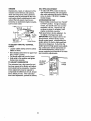
TRAINING
° Do not operate
• Read the Owner's Manual carefully. Be
thoroughly familiar with the controls and
the proper use of the equipment. Know
how to stop the unit and disengage the
controls quickly.
o Never allow children to operate the
equipment. Never allow adults to operate the equipment without proper
instruction°
= Keep the area of operation clear of all
persons, particularly small children, and
pets.
°
°
°
o
°
•
PREPARATION
° Thoroughly inspect the area where the
equipment is to be used and remove all
foreign objects.
° Disengage al! clutches and shift into
neutral before starting the engine (motor).
°
2
the equipment
without
wearing adequate outer garments. Wear
footwear that will improve footing on
slippery surfaces.
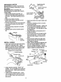
Handle fuel wi[h care; it is highly flammable.
Use an approved fuel container.
Never add fuel to a running engine or
hot engine.
Fill fuel tank outdoors with extreme care.
Never fill fuel tank indoors.
Replace gasoline cap securely and
clean up spilled fuel before restarting.
Use extension cords and receptacles as
specified by the manufacturer for all
units with electric drive motors or electric
starting motors.
Never attempt to make any adjustments
while the engine (motor) is running
(except where specifically recommended by manufacturer).
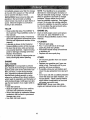
MAINTENANCE
OPERATION
o Do not put hands or feet near or under
rotating parts.
,, Exercise extreme caution when operating on or crossing gravet drives, walks,
or roads. Stay alert for hidden hazards
or traffic. Do not carry passengers.
o After striking a foreign object, stop the
engine (motor), remove the wire from
the spark plug, thoroughly inspect the
tiller for any damage, and repair the
damage before restarting and operating
the tiller.
o Exercise caution to avoid slipping or
falling.
° If the unit should start to vibrate abnormally, stop the engine (motor) and check
immediately for the cause. Vibration is
generally a warning of trouble.
° Stop the engine (motor) when leaving
the operating position.
• Take all possible precautions when leaving the machine unattended. Disengage
the tines, shift into neutral, and stop the
engine.
,, Before cleaning, repairing, or inspecting,
shut off the engine and make certain all
moving parts have stopped.. Disconnect
the spark plug wire, and keep the wire
away from the plug to prevent accidental
starting. Disconnect the cord on electric
motors.
o Do not run the engine indoors; exhaust
fumes are dangerous.
o Never operate the tiller without proper
guards, plates, or other safety protective
devices in place.
, Keep children and pets away.
• Do not overload the machine capacity
by attempting to till too deep at too fast a
rate.
° Never operate the machine at high
speeds on slippery surfaces. Look
behind and use care when backing.
• Never allow bystanders near the unit.
° Use only attachments and accessories
approved by the manufacturer of the
tiller.
• Never operate the tiller without good visibility or light.
° Be careful when tilling in hard ground.
The tines may catch in the ground and
propel the tiller forward. If this occurs,
let go of the handlebars and do not
restrain the machine.
AND STORAGE
o Keep machine, attachments, and
accessories in safe working condition.
o Check shear pins, engine mounting
bolts, and other bolts at frequent intervals for proper tightness to be sure the
equipment is in safe working condition.
° Never store the machine with fuel in the
fuel tank inside a building where ignition
sources are present, such as hot water
and space heaters, clothes dryers, and
the like. Allow the engine to cool before
storing in any enclosure.
o Always refer to the operator's guide
instructionsfor important details if the
tiller is to be stored for an extended perid.
CAUTION: Always disconnect spark
plug wire and place wire where it cannot
contact spark plug in order to prevent accidental starting when setting up, transporting, adjusting or making repairs.
WARNING
The engine exhuast from this product contains chemicals known to the State of
California to cause cancer, birth defectd, or
other reproductive harm.
3
PRODUCT
SPECIFICATIONS
MAINTENANCE
AGREEMENT
A Sears Maintenance Agreement is available on this product. Contact your nearest
Sears store for details.
--IORSEPOWER:
5,5HP
DISPLACEMEr-fT:
t3 CU. IN.
GASOLINE CAPACITY:
4 Quarts
Unleaded Regular
OIL (API-SF/SG!SH):
SAE 30
(CAPACITY: 20 oz.)
(Above 32°F)
SAE 5W-30
CUSTOMER
o Read and observe the safety rules.
,, Follow a regular schedule in maintaining, caring for and using your tiller.
o Follow the instructions under the
"Customer Responsibilities" and "Storage" sections of this Owner's Manual°
(Below 32°F)
SPARK PLUG :
(GAP: .030")
RESPONSIBiLiTIES
Champion RJ19LM
WARNING= This unit is equipped with an
internal combustion engine and should not
be used on or near any unimproved forestcovered, brush-covered or grass covered
land unless the engine's exhaust system is
equipped with a spark attester meeting
applicable local or state laws (if any). if a
spark arrester is used, it should be maintained in effective working order by the
operator.
In the state of California the above is
required by law (Section 4442 of the
California Public Resources Code). Other
states may have similar laws. Federal
laws apply on federal lands° See your
Sears Authorized Service Center for spark
arrester. Refer to the Repair Parts section
of this manual for part number.
Congratulations on your purchase of a
Craftsman Tiller. It has been designed, engineered and manufactured to giveyou the
best possible dependability and performance.
Should you experience any problems you
cannot easily remedy, please contact your
nearest authorized Sears Service
Center/Department.
We have competent,
well-trained technicians and the proper
tools to service or repair this unit.
Please read and retain this manual. The
instructions will enable you to assemble
and maintain your tiller properlyoAlways
observe the "SAFETY RULES".
Your new tiller has been assembled at the
factory with exception of those parts left
unassembled for shipping purposes. To
ensure safe and proper operation of your
tiller all parts and hardware you assemble
must be tightened securely. Use the correct tools as necessary to insure proper
tightness.
These accessories were available when the tiller was purchased. They are also available at most Sears Retail outlets and Service Centers. Most Sears Stores can order
repair parts for you when you provide the model number of your tiller.
ENGINE
SPARK PLUG
TILLER
AfR FI_LTER |
GAS CAN
ENGINE OIL
PERFORMANCE
'" FU__ENER
TILLER MAINTENANCE
........
.ELT ............
.................
_,Es
HAIRPIN CUP
4
Your new tiller has been assembled at the factory with exception of those parts left
unassembled for shipping purposes. To ensure safe and proper operation of your tiller
all parts and hardware you assemble must be tightened securely. Use the correct tools
as necessary to insure proper tightness.
TOOLS
REQUIRED
FRONT
FOR ASSEMBLY
A socket wrench set will make assembly
easier. Standard wrench sizes are listed.
(t) Utility knife
(1) Wire cutter
(1) Tire pressure gauge
(1) Screwdriver
(1) Pair of pliers
(1) 9/16" wrench
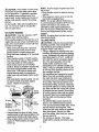
OPERATOR'S POSITION
When right or left hand is mentioned in
this manual, it means when you are in
the operating position (standing behind
tiller handles).
RIGHT
LEFT
L1
OPERATOR'S
POSITION
CONTENTS OF HARDWARE PACK
(2) Handle
Locks
(1) Carriage Bolt
3/8-'16 UNC x I Gr. 5
(1) Center Locknut
3/8-16 UNC
(1) Cable Clip
I
(2) Hairpin
Clips
(1) Pivot Bolt
3/8-16 UNC Grade
(1) Flat Washer
13/32 x I x 11 Ga.
Extra Shear
(1) Handle Lock Lever
Pins & Clips
r
5
UNPACKBNG CARTON
,_CAUTION:
Be careful of exposed staples when handling or disposing of cartoning material.
IMPORTANT:When unpacking and
assembling tiller, be careful not to stretch
or kink cables.
,, While holding handle assembly, cut
cable ties securing handle assembly to
top frame. Let handle assembly rest on
tiller,
o Remove top frame of carton.
Slowly ease handle assembly up and
place on top of carton_
o Cut down right hand front and right hand
rear comers of carton, lay side carton
wall down.
o Remove packing material from handle
assembly.
o Separate shift rod from handle assembly.
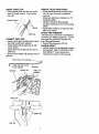
HNSTALL HANDLE
° Insert one handle lock (with teeth facing
outward) in gearcase notch. (Apply
grease on smooth side of handle lock to
aid in keeping lock in place until handle
assembly is lowered into position.)
Viewed from r.h. side of tilter
,_,,_,__G
_,:._
zf
'._
_ "::_
Tighten handle lock
'_i_,,, lever to hold
Leverto Move
/__
° Insert pivot bolt in front part of plate and
tighten,
= Cut down remaining corners of carton
and lay panels flat.
° Lower the handle assembly. Tighten nut
on carriage bolt so handle moves with
some resistance, This will allow for easier adjustment,
o Place flat washer on threaded end of
handle lock lever.
• Insert handle lock lever through handle
base and gearcase. Screw in handle
lock lever just enough to hold lever in
place.
° Insert second handle lock (with teeth
inward) in the slot of the handle base
(just inside of washer),
o Raise handle assembly to highest position and securely tighten handle lock
lever by rotating clockwise. Leaving
handle assembly in highest position will
make it easier to connect shift rod.
Handle Lock
Gearcase
\
Flat Washer
Handle Lock
\
eHandle Assembly
arcase Notch
/
_;_,_,
Handle Assembly
":".:..:. _._ ,,, .UP PosllJon
Slot
Rear Cartridge
Bolt
Hand,eLock
Pivot Bolt
Handle Base
° Grasp handle assembly, Hold in "up"
position. Be sure handle lock remains in
gearcase notch, Slide handle assembly
into position,
• Rotate handle assembly down. Insert
rear carriage bolt first, with head of bolt
on L,H. side of tiller and loosely assemble Iocknut.
6
INSERTCABLE CLIP
• Insert plastic cable clip into hole on the
back of handle column, Push cables
into clipo
Handle Column
Cables
Cable Clip
CONNECT SHIFT ROD
= Insert end of shift rod farthest from bend
into hole of shift lever indicator°
o Insert hairpin clip through hole of shift
rod to secure.
° Insert other end of shift rod into hole in
shift lever,
° Insert second hairpin clip through hole of
shift rod.
REMOVE TILLER FROM CRATE
- Adjust handle assemby to lowest position_Be sure lock lever is tightened
securely.
,, Make sure shift lever indicator is in "N"
(neutral) position,
° Tilt tiller forward by lifting handle.
Separate cardboard cover from leveling
shield°
o Rotate tiller handle to the right and pull
tiller out of carton.
CHECK TIRE PRESSURE
The tires on your unit were overinflated at
the factory for shipping purposes, Correct
and equal tire pressure is important for
best tilling performance.
o Reduce tire pressure to 20 PSI.
HANDLE HEIGHT
o Handle height may be adjusted to better
suit operator, (See 'q'O ADJUST HANDLE HEIGHT" in the Service and
Adjustments section of this manual),
Attach this end to shift lever
0_-_...Attach this End To shift
Lever Indicator
Shift Rod
Hairpin Clip
k
Shift Rod
Shift Lever
Indicator
Shift Lever
,, i
"_
'
Ha_rpLnClip
Shift
_,
_
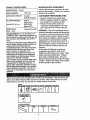
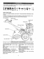
These symbols may appear on your Tiller or in literature
Learn and understand their meaning,
supplied
with the product,
_
NEtrtRAL
REVERSE
CAUI'_GN
OR WARNI_'_G
ENGINE
ON
ENGINE
OFF
FAST
SLOW
CHGKE
STOp
FUEL
_O
OIL
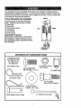
KNOW YOUR TILLER
READ THIS OWNER'S
TILLER°
MANUALAND
SAFETY
RULES
BEFORE
OPERATING
Compare the illustrations with your tiller to familiarize yourself with the location
ous controls and adjustments,
Save this manual for future reference,
Drive Control Bar
YOUR
of vari-
Throttle Control
Shift Lever
Fuel Shut-Off
valve
Choke Control
\
Shift Lever Indicator
Depth
Leveling
Recoil
Starter
Handle
Outer Side Shield
MEETS ANSI SAFETY
Our tillers conform
DRIVE
tines.,
DEPTH
CONTROL
to the safety standards
of the American
National
SHIFT LEVER
BAR - Used to engage
Standards
Institute.
- Used to shift transmission
gears,
STAKE
- Controls
SHIFT LEVER
depth at which
tiller will dig,
LEVELING
SHIELD
o Levels tilled soil.
OUTER SIDE SHIELD - Adjustable
tect small plants from being buried
THROTTLE
engine
REQUIREMENTS
CONTROL
INDICATOR
_ Shows which
gear the transmission
is in,
RECOIL
HANDLE
STARTER
- Used
to
start the engine.
to pro-
CHOKE CONTROLa cold engine.,
- Used to control
speed..
8
Used
when starting
The operation of any tiller can result in foreign objects thrown into the eyes,
which can result in severe eye damage. Always wear safety glasses or eye
shields before starting your tiller and while tilling. We recommend a wide
vision safety mask over the spectacles or standard safety glasses.
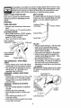
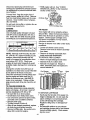
DEPTH STAKE
HOW TO USE YOUR TALLER
The depth stake can be raised or lowered
Know how to operate all controls before
to allow you more versatile tilling and cultiadding fuel and oil or attempting to start
vating, or to more easily transport your
engine.
tiller.
STOPPING
TINES AND DRIVE
o Release drive control bar to stop movement.
o Move shift lever to "N" (neutral) position.
STOPPING ENGINE
,, Move throttle control to "STOP" position.
if equipped with stop switch, move
switch to "STOP" position.
o Never use choke to stop engine.
Drive Control Bar
"ENGAGED" Position
Shallowest Tilling
(Cultivating)
"" Transport Position
Deepest Tilling
Depth Stake ,i_
Shift Lever
Drive
Bar
"DISENGAGED"
Position
Throffie
TINE OPERATION - WITH WHEEL
DRIVE
° Always release drive control bar before
moving shift lever into another position.
= Tine movement is achieved by moving
shift lever to ( _ ) till position and
engaging drive control bar,
FORWARD - WHEELS ONLY/TINES
STOPPED
° Release drive control bar and move shift
lever indicator to "F" (,forward)position.
Engage drive control bar and tiller will
move forward.
REVERSE - WHEELS ONLY/TINES
STOPPED
° DO NOT STAND DIRECTLY BEHIND
TILLING
° Release depth stake_pin. Pull the depth
stake up for increased tilling depth.
Place depth stake Pin in hole of depth
stake to lock in position.
o Place shift lever indicator in till position.
,, Hold the drive control bar against the
handle to start tilling movement. Tines
and wheels will both turn.
° Move throttle control to "FAST" position
for deep tilling. To cultivate, throttle con _
trol can be set at any desired speed,
depending on how fast or slow you wish
to cultivate.
IMPORTANT: Always release drive control
bar before moving shift lever into another
position.
Depth Stake Pin
Position
° Release the drive control bar.
° Move throttle control to "SLOW" position.
, Move shift lever indicator to "R"
(reverse) position.
° Hold drive control bar against the handle
to start tiller movement.
"Locked"
Position
Nut "B"
Nut "A"
Outer Side Shield
9
TURNING
o Release the drive control bar.
o Move throttle control to "SLOW" position.
o Place shift lever indicator in "F" (forward)
position. Tines will not turn.
Lift handle to raise tines out of ground.
o Swing the handle in the opposite direction you wish to turn, being careful to
keep feet and legs away from tines.
o When you have completed your turnaround, release the drive control bar and
lower handle. Place shift lever in till
position and move throttle control to desired speed. To begin tilling, hold drive
control bar against the handle.
OUTER SIDE SHIELDS
The back edges of the outer side shields
are slotted so that the shields can be
raised for deep tilling and lowered for shallow tilling to protect smaU plants from
bei.n,_buried, Loosen nut "A" in slot and
nut "B", Move shield to desired position
(both sides). Retighten nuts.
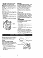
CHECK ENGINE OULLEVEL
o The engine in your unit has been
shipped, from the factory, already filled
with SAE 30 summer weight oil.
• With engine level, clean area around oil
filler plug and remove plug.
o Engine oil should be to point of overflowing when engine is level. For approximate capacity see "PRODUCT SPECIFICATIONS" on page 4 of this manual.
All oil must meet A.P.I. Service
Classification SF, SG or SH.
o For cold weather operation you should
change oil for easier starting (See oil
viscosity chart in the Customer
Responsibilities section of this manual).
o To change engine oil, see the Customer
Responsibilities section in this manual°
Oil Level
OiF
Filler
Plug
TO TRANSPORT
,_kCAUTION: Before lifting or transporting, allow tiller engine and muffler to cool.
Disconnect spark plug wire. Drain gasoline from fuel tank.
AROUND THE YARD
° Release the depth stake pin. Move the
depth stake down to the top hole for
transporting the tiller. Place depth stake
pin in hole of depth stake to lock in position. This prevents tines from scuffing
the ground.
° Place shift lever indicator in "F" (forward)
position for transpodingo
° Hold the drive control bar against the
handle to start tiller movement. Tines
wilt not turn.
o Move throttle control to desired speed.
AROUND TOWN
• Disconnect spark plug wire.
- Drain fuel tank.
• Transport in upright position to prevent
oil leakage.
BEFORE
STARTING
ENGINE
IMPORTANT: Be very careful not to allow
dirt to enter the engine when checking or
adding oil or fuel. Use clean oil and fuel
and store in approved, clean, covered containers, use clean fill funnels.
10
Oil Drain Plug
ADD GASOLINE
• Fill fuel tank. Use fresh, clean, regular
unleaded gasoline. (Use of leaded
. gasoline will increase carbon and lead
oxide deposits and reduce valve life.
IMPORTANT: When operating in temperatures below 32°F (0°C), use fresh, clean,
winter grade gasoline to help insure good
cold weather starting.
WARNING: Experience indicates that alcohol blended fuels (called gasohol or using
ethanol or methanol) can attract moisture
which leads to separation and formation of
acids during storage. Acidic gas can damage the fuel system of an engine while in
storage. To avoid engine problems, the
fuel system should be emptied before
storage of 30 days or longer. Drain the
gas tank, start the engine and let it run
until the fuel lines and carburetor are
empty. Use fresh fuel next season. See
Storage section of this manual for additional information. Never use engine or carburetor cleaner products in the fuel tank or
permanent damage may occur.
,_kCAUTION; Fill to within 1/2 inch of top
of fuel tank to prevent spills and to allow
for fuel expansion. If gasoline is accidentally spilled, move machine away from
area of spill. Avoid creating any source of
ignition until gasoline vapors have disappeared.
Do not overfill. Wipe off any spilled oil or
fuel. Do not store, spill or use gasoline
near an open flame.
TO START ENGINE
,_CAUTION:
Keep tine control in "OFF"
position when starting engine.
When starting engine for the first time or if
engine has run out of fuel, it will take extra
pulls of the recoil starter to move fuel from
the tank to the engine.
= Make sure spark plug wire is properly
connected and access cover is completely closed to create proper seal.
o Move shift lever indicator to "N" (neutral)
position.
o Place throttle control in "FAST" position.
o Turn fuel shut-off valve to "ON" position.
o Push stop switch to "ON" position.
o Move choke control to full "CHOKE"
position. Grasp recoil starter handle with
one hand and grasp tiller handle with
other hand. Pull rope out slowly until
engine reaches start of compression
cycle (rope will pull slightly harder at this
point).
• Pull recoil starter handle quickly. Do not
let starter handle snap back against
starter. Repeat if necessary.
Choke Control
Starter
Handle
1/4Turn {_ I t_
}),
Counter- _{L_.J,JJ),/-_
Ctockwise'.---_-"
Switch
Fuel shut-off Valve
° If engine fires but does not start, move
choke control to half choke position. Pull
recoil starter handle until engine starts.
• When engine starts, slowly move choke
control to "RUN" position as engine
warms up.
NOTE: A warm engine requires less choking to start.
° Move throttle control to desired running
position°
o Allow engine to warm up for a few minutes before engaging tines.
NOTE: If at a high altitude (3000 feet) or
in cold temperatures (below 32°F), the carburetor fuel mixture may need to be
adjusted for best engine performance.
See "TO ADJUST CARBURETOR" in the
Service and Adjustments section of this
manual.
NOTE: If engine does not start, see troubleshooting points.
TILLING HINTS
_IkCAUTION: Until you are accustomed to
handling your tiller, start actual field use
with throttle in slow position (mid-way
between "FAST" and "iDLE").
° Tilling is digging into, turning over, and
breaking up packed soil before planting.
Loose, unpacked soil helps root growth.
Best tilling depth is 4" to 6". A tiller will
also clear the soil of unwanted vegetation. The decomposition of this vegetable matter enriches the soil.
Depending on the climate (rainfall and
wind), it may be advisable to till the soil
at the end of the growing season to further condition the soil.
o Soil conditions are important for proper
tilling. Tines will not readily penetrate
dry, hard soil which may contribute to
excessive bounce and difficult handling
of your tiller. Hard soil should be moistened before tilling; however, extremely
wet soil will "bali-up" or clump during tilling. Wait until the soil is less wet in order
to achieve the best results. When tilling
in the fall, remove vines and long grass
to prevent them from wrapping around
the tine shaft and slowing your tilling
operation.
° You will find tilling much easier if you
leave a row untilled between passes.
Then go back between tilled row& There
are two reasons for doing this. First,
wide turns are much easier to negotiate
than about-faces. Second, the tiller
won't be pulling itself, and you, toward
the row next to it.
= Do not lean on handle. This takes
weight off the wheels and reduces traction.
11
Toget througha
really tough section of
sod or hard ground, apply upward pressure on handle or lower the depth stake.
T_NI= SHEAR PiNS
The tine assemblies on your tiller are
secured to the tine shaft with shear pins
(See "TINE REPLACEMENT" in the
Service and Adjustments section of this
manual).
If the tiller is unusually overloaded or
jammed, the shear pins are designed to
break before internal damage occurs to
the transmission,
o If shear pin(s) break, replace only with
those shown in the Repair Parts section
of this manual
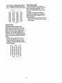
CULTIVATING
Cultivating is destroying the weeds
between rows to prevent them from robbing nourishment and moisture from the
plants. At the same time, breaking up the
upper layer of soil crust will help retain
moisture in the soil. Best digging depth is
1" to 3" (2.5-7.5 cm). Lower the outer side
shields to protect small plants from being
buried.
. Cultivate up and down the rows at a
speed which will allow tines to uproot
weeds and leave the ground in rough
condition, promoting no further growth of
weeds and grass.
0 O0 0 _0
0 O0 0 0
0 O0 0 _0
0 O0 0 0
12
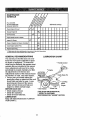
...............
SCHEDULEMAINTENANCE
AS YOUCOMPLETE
RE U SERVIOE
R
,,,,,,,,,,,,,,,,,,,
/1/_/_
_
_/
.......
/_Z_'Z_'_"/._-¢i
SERVtCE DATES
,,i,,,,i,,u
Check Engine Oil Leve!
_'
_/
I
ChangeEngineOil
_t,2
Oil Pivot Points
V _'
...........................................
:::::
Inspect
Spark Arrester I Mufffer
..................................
inspect Air Screen
.............................
.
.
;
;
,,: ......
;
,,,,.,,,_,_-
_'
.
L,
I/'
i t
t.
,
Clean or Replace Air Cleaner Cartridge
6/2
Clean Engine Cylinder Fins
_ .....
.epla=
SpaP,!,"g
......
V'
_-
== ......... :
.
I
i
1 - Ch_,ngamore oftenwhenoperating undera heavyload or in highambienttemperatures,
2- Servicemore oftenwhenoperatingIn dirtyor dust'tcortdtUons,
GENERAL
LUBRICATION
RECOMMENDATIONS
The warranty on this tiller does not cover
items that have been subjected to operator abuse or negligence. To receive full
value from the warranty, the operator must
maintain tiller as instructed in this manual
Some adjustments will need to be made
periodically to properly maintain your tiller.
All adjustments in the Service and
Adjustments section of this manual should
be checked at least once each season.
• Once a year you should replace the
spark plug, clean or replace air filter, and
check tines and belts for wear. A new
spark plug and clean air filter assure
proper air-fuel mixture and help your
engine run better and last longer.
BEFORE EACH USE
• Check engine oil level.
• Check tine operation.
° Check for loose fasteners.
LUBRICATION
Keep unit well lubricated (See =LUBRICATION CHART").
CHART
* Throttle Control
* Depth Stake Pin
Leveling
Shield
Hinges
* Idler Bracket
Wheel Hub
* SAE 30 OR 10W-30 MOTOR OIL
** REFER TO CUSTOMER
RESPONSIBILITIES "ENGINE" SECTION
13
Disconnect spark plug wire before performing any maintenance (except carburetor adjustment) to prevent accidental starting of engine°
Prevent fires! Keep the engine free of
grass, leaves, spilled oil, or fuel. Remove
fuel from tank before tipping unit for maintenance. Clean muffler area of all grass,
dirt, and debris.
,, Refill engine with oil. See "CHECK
ENGINE OIL LEVEL" in the Operation
section of this manual.
O1t Drain Plug_
Do not touch hot muffler or cylinder fins as
contact may cause burns.
ENGINE
LUBRICATION
Use only high quality detergent oil rated
with API service classification SF, SG or
SFI, Select the oil's SAE viscosity grade
according to your expected temperature°
....
IF
"L'O=
_
_
_
4r_
60*
80,
I
lo0"
oc._
._- ._.
_ ..............
;_..............
_.
_. _.
TEMPE,A_RE
_NaEA,TICI_ATED
BE_RE
NEXT
OIL
C,_OE
NOTE: Although multi-viscosity' oils (5W30, 10W-30, etc.) improve starting in cold
weather, these multi-viscosity oils will
result in increased oil consumption when
used above 32°F (0°C). Check your
engine oil level more frequently to avoid
possible engine damage from running low
on oil.
Change the oil after ever,./50 hours of
operation or at least once a year if the tiller
is not used for 50 hours in one year.
Check the crankcase oil level before starting the engine and after each five (5)
hours of continuous use. Add SAE 30
motor oil or equivalent. Tighten oil filler
plug securely each time you check the oil
level.
TO CHANGE ENGINE OIL
Determine temperature range expected
before oil change. All oil must meet API
service classification SF, SG or SH.
• Be sure tiller is on level surface.
= Oil will drain more freely when warm.
° Use a funnel to prevent oil spill on tiller,
and catch oil in a suitable container,
° Remove drain plug.
° Tip tiller forward to drain oil.
• After oil has drained completely, replace
oil drain plug and tighten securely.
° Remove oil filler plug. Be careful not to
allow dirt to enter the engine.
\\ Oil Level
Oil Filler Plug
AIR FILTER
Your engine will not run properly using a
dirty air filter. Clean the foam pre-cleaner
after ever,./50 hours of operation or every
season, Service paper cartridge every
100 hours of operation or every season,
whichever occurs first,
Service air cleaner more often under dusty
conditions.
• Loosen air cleaner cover screws.
Remove cover and air cleaner assembly
from base.
• Remove air cleaner asssembly from
inside cover and disassemble.
TO SERVICE PRE-CLEANER
o Wash it in liquid detergent and water.
o Squeeze it dry in a clean cloth.
° Saturate it in engine oil. Wrap it in
clean, absorbent cloth and squeeze to
remove excess oil.
Pre-Cleaner
Cover
T_ Slot
Base
Retair
Oover Screws
TO SERVICE CARTRIDGE
° Gently tap the flat side of the paper cartridge to dislodge dirt. Do not wash the
paper cartridge or use pressurized air,
as this will damage the cartridge.
Replace a dirty, bent, or damaged cartridge.
o Re-assemble retainer on pre-cleaner
and cartridge (screen side of pre-cleaner
toward cartridge pleats). Place assem.
bly into cover.
14
o Inserttabs on cover !nto slots in base
MUFFLER
tighten cover screws securely.
,_cndAUTION.
Petroleum solvents, such
as kerosene, are not to be used to clean
cartridge. They may cause deterioration of
the cartridge° Do not oil cartridge° Do not
use pressurized air to clean or dry car -_
tridgeo
COOLING SYSTEM
Your engine is air cooled. For proper
Do not operate tiller without muffler. Do not
tamper with exhaust system_ Damaged
mufflers or spark arresters could create a
fire hazard. Inspect periodically and replace if necessary. If your engine is
equipped with a spark arrester screen
assembly, remove every 50 hours for
cleaning and inspection. Replace if damaged.
SPARK PLUG
Replace spark plugs at the beginning of
each tilling season or after every 50 hours
of use, whichever comes first° Spark plug
type and gap setting is shown in "PRODUCT SPECIFICATIONS" on page 4 of this
manual.
engine performanceand longlife keep
your engine clean.
,, Clean air screen frequently using a stiffbristled brush.
o Remove blower housing and clean as
necessary,
• Keep cylinder
finsfreeofdirtand chaff.
TRANSMISSION
Your transmission is sealed and will only
require lubricationif se_iced.
__
Blower
Housing
Air Screen
CLEANING
° Clean engine, wheels, finish, etc. of all
foreign matter.
o Keep finished surfaces and wheels free
of all gasoline, oil, etc.
= Protect painted surfaces with automotive
type wax.
'
We do not recommend using a garden
hose to clean your unit unless the muffler,
air filter and carburetor are covered to
keep water out. Water in engine can result
in a shortened engine life.
,_CAUTION:
Disconnect spark plug wire
from spark plug and place wire where it
cannot come into contact with plug.
Handle (High) Position
TILLER
__
TO ADJUST HANDLE HEIGHT
Select handle height best suited for your
tilling conditions. Handle height will be different when tiller digs into soil
° First loosen handle lock lever.
° Handle can be positioned at different
settings between =HIGH" and "LOW"
positions.
° Retighten handle lock lever securely
after adjusting.
Hand__
15
:: '_-:__ Handle Lock Lever
TiRE CARE
Belt Guard
CAUTION: When mounting tires, unless
beads are seated, overinflation can cause
an explosion.
o Maintain 20 pounds of tire pressure. If
tire pressures are not equal, tiller will
pull to one side;
o Keep tires free of gasoline or oil which
can damage rubber.
TO REMOVE WHEEL
Cap Nut
and
Washer
p and Clevis Pin
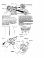
TO REPLACE GROUND DRIVE
BELT
= Remove belt guard as described in "TO
REMOVE BELT GUARD".
• Loosen belt guides "A" and "B" and also remove stud "C"°
- Remove old belt by slipping off engine
pulley first then remove from the pulley.
° Place new belt in groove of transmission pulley and into engine pulley. BELT
MUST BE IN GROOVE ON TOP OF
IDLER PULLEY. NOTE POSITION OF
BELT TO GUIDES.
= Tighten belt guides "A" and "B" and stud
o Place blocks under transmission to keep
tiller from tipping.
o Remove outer side shield by removing
nuts "A" and "B".
o Remove inner side shield by removing
nuts "C" and "D".
o Remove hairpin clip and clevis pin from
wheel.
o Remove wheel and tire.° Repair tire and
reassemble.
Clevis
Pin
_'C
't"
= Check belt adjustment as described
below.
Q Replace bett guard.
= Reposition wheel and replace clevis pin
and hairpin clip.
Hairpin
GROUND
MENT
Clip
Nut "B"
Hah
Hex Nut and
•Washer
(Located
Behind Tire)
Inner Side Shield
Outer Side Shield
TO REMOVE BELT GUARD
NOTE: For ease of removal, remove hairpin clip and clevis pin from left wheel. Pull
wheel out from tiller about 1 inch.
, Remove two (2) cap nuts and washers
from side of belt guard.
o Remove hex nut and washer from bottom of belt guard (located behind
wheel).
° Pull belt guard out and away from uniL
° Replace belt guard by reversing above
procedure.
DRIVE BELT ADJUST-
For proper belt tension, the extension
sloringshould have about 5/8 inch stretch
when drive control bar is in "ENGAGED"
position° This tension can be attained as
follows:
o Loosen cable clip screw securing the
drive control cable.
o Slide cable forward for less tension and
rearward for more tension until about 5/8
inch stretch is obtained while the drive
control bar is engaged°
= Tighten cable clip screw securely.
16
ip Screw
Engine Putley
Drive Control Cable
Stud
Idler Pulley
_Extension
Transr
Spring"
Pulley
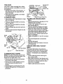
TINE REPLACEMENT
,_CAUTION: Tines are sharp. Wear
gloves or other protection when handling
tines.
A badly wom tine causes your tiller to work
harder and dig more shallow. Most important, worn tines cannot chop and shred
organic matter as effectively nor bury it as
deeply as good tines. A fine this worn
needs to be replaced,
° To maintain the superb tilling performance of this machine the tines should
be checked for sharpness, wear, and
bending, particularly the tines which are
next to the transmission. If the gap
between the tines exceeds 3-1/2 inches
they should be replaced or straightened
as necessary.
e New tines should be assembled. Sharpened tine edges will rotate rearward
from above.
New Tine
_ne
t
I
3-1/2' Max
Counter"line
_
,_
_
t
I
}-----
Hairpin Clip
Rotation
Sharp Egde
Sharp Ed
Shear Pin
Shear Pin
_7
ENGINE
Maintenance, repair, or replaceent of the
emission control devices and systems,
which are being done at the customers
expense, may be performed by any nonroad engine repair establishment or individual. Warranty repairs must be performed by an authorized engine manufacturer's sercie outlet.
Cable
Clamp Screw
TO ADJUST THROTTL_
CABLE
CONTROL
, Loosen cable clamp screw to allow
cable to move.
o Move throttle control lever on upper handle to "FAST" position.
o Pull throttle cable out to end of travel
o Hold cable in this position and tighten
clamp screw securely.
TO ADJUST CARBURETOR
The carburetor has a high speed jet and
has been preset at the factory and adjustment should not be necessary. However,
minor adjustments may be required to
compensate for differences in fuel, temperature, altitude or toad. If the carburetor
does need adjustment, proceed as follows.
IDLE RPM ADJUSTMENT
° To adjust idle RPM, rotate throttle link-.
age counterclockwise and hotd against
stop while adjusting idle speed adjusting
screw to obtain 1750 RPM. Release
throttle linkage.
ACCELERATION TEST
° Move throttle control lever from "SLOW"
to "FAST_'position. If engine hesitates
or dies, turn needle valve out (counterclockwise) 1/8 turn_ Repeat test and
continue to adjust, if necessary, until
engine accelerates smoothly.
High speed stop is factory adjusted. Do
not adjust or damage may result.
IMPORTANT: Never tamper with the engine governor, which is factory set for
proper engine speed, overspeeding the
engine above the factory high speed setting can be dangerous, if you think the
engine-governed high speed needs adjusting, contact your nearest authorized service center/department, which has the
proper equipment and experience to make
any necessary adjustments.
Idte Speed
Ad
Screw
Linkage
Valve
!8
Immediatelyprepare your tiller for storage
at the end of the season or if the unit will
not be used for 30 days or more.
_kCAUTION: Never store the tiller with
gasoline in the tank inside a building
where fumes may reach an open flame or
spark. Allow the engine to cool before
storing in any enclosure,
TILLER
o Clean entire tiller (See "CLEANING"
in
the Customer Responsibilities
section of
this manual).
o Inspect and replace belts, if necessary
(See belt replacement
instructions in the
Service and Adjustments
section of this
manual).
• Lubricate as shown in the Customer
Responsibilities
section of this manual°
o Be sure that all nuts, bolts and screws
are securely fastened.
Inspect moving
parts for damage, breakage and wear.
Replace if necessary.
• Touch up all rusted or chipped paint surfaces; sand lightly before painting.
ENGINE
FUEL SYSTEM
IMPORTANT: It is important to prevent
gum deposits from forming in essential fuel
system parts such as the carburetor, fuel
filter, fuel hose, or tank during storage.
also, experience indicates that alcohol
blended fuels (called gasohol or using
ethanol or methanol) can attract moisture
which leads to separation and formation of
acids during storage. Acidic gas can damage the fuel system of an engine while in
storage.
° Drain the fuel tank.
• Start the engine and let it run until the
fuel lines and carburetor are empty.
o Never use engine or carburetor cleaner
products in the fuel tank or permanent
damage may occur.
o Use fresh fuel next season.
NOTE: Fuel stabilizer is an acceptable
alternative in minimizing the formation of
fuel gum deposits during storage, Add stabilizer to gasoline in fuel tank or storage
container. Always follow the mix ratio
found on stabilizer container. Run engine
at least 10 minutes after adding stabilizer
to allow the stabilizer to reach the carburetor. Do not drain the gas tank and carburetor if using fuel stabilizer.
ENGINE
OIL
Drain oil (with engine warm) and replace
with clean oil. (See "ENGINE" in the
Customer Responsibilities section of this
manual).
CYLINDER
° Remove spark plug,
,, Pour 1 ounce (29 ml) of oil through
spark plug hole into cylinder.
° Pull starter handle slowly several times
to distribute oil.
o Replace with new spark plug.
OTHER
° Do not store gasoline from one season
to another.
° Replace your gasoline can if your can
starts to rust. Rust and/or dirt in your
gasoline will cause problems.
o If possible, store your unit indoors and
cover it to give protection from dust and
dirt.
o Cover your unit with a suitable protective
cover that does not retain moisture, Do
not use plastic. Plastic cannot breathe
which allows condensation to form and
will cause your unit to rust,
IMPORTANT: Never cover tiller while
engine and exhaust areas are still warm,
19
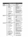
PROBLEM
Will not start
CAUSE
CORRECTION
1, Out of fuelo
2. Engine not "CHOKED"
properly,
3, Engine flooded.
5. Water in fuel.
6, Clogged fuel tank,
7. Loose spark plug wire.
8, Bad spark plug or
improper gap,
9. Carburetor out of adjustment,
and refill tank with fresh gasoline.
6. Remove fuel tank and clean.
7. Make sure spark plug wire is seat
ed propedy on plug.
8. Replace spark plug or adjust gap.
9. Make necessary adjustments.
1. Throttle control not set
1, Place throttle control in "FAST"
properly.
2, Dirty air cleaner.
position.
2. Clean or replace air cleaner car
tridge,
3. Replace spark plug or adjust gap°
3. Bad spark plug or
improper gap.
4. Stale or dirty fuel.
4, Drain fuel tank and refill with fresh
5. Loose spark plug wire.
6, Carburetor out of,
adjustment,
Loss of power
Operation section.
3_ Wait several minutes before
attempting to start,
4. Clean or replace air cleaner car
tridge_
5. Drain fuel tank and carburetor,
4. Dirty air cleaner.
Hard to start
1. Fill fuel tank.
2. See "TO START ENGINE" in.the
t. Engine is overloaded.
2. Dirty air cleaner°
3, Low oil level!dirty oil.
4. Faulty spark plug.
5. Oil in fuel.
6. Stale or dirty fuel,,
7, Water in fi_el.
8. Clogged fuel tank,
9, Spark plug wire loose°
wire.
10. Dirty engine air screen,
11_ Dirtylclogged muffler,
12. Carburetor out of
adjustment.
13. Poor compression.
2O
gasoline,
5._ Make sure spark plug wire is seat
ed propedy on plug.
6. Make necessary adjustments,
1. Set depth stake and wheels for
shallower tilling_
2, Clean or replace air cleaner car
tddge,
3, Check oil levellchange oil,
4. Clean and regap or change spark
plug,
5, Drain and clean fuel tank and
refill, and clean carburetor°
6. Drain fuel tank and refill with fresh
gasoline,
7, Drain fuel tank and carburetor,
and refill tank with fresh gasoline,
8, Remove fuel tank and clean,
9, Connect and tighten spark plug
10. Clean engine air screen°
tl. Clean/replace muffler,
12. Make necessary' adjustments°
13. Contact an authorized Sears
Service Center/Department.
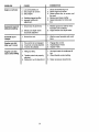
PROBLEM
Engine overheats
CORRECTION
CAUSE
1, Low oil level/dirty oil.,
2. Dirt/engine air screen.
3. Dirty engine.
4. Partially plugged muffler.
5, Improper carburetor
adjustment.,
1_ Check oil level/change oil.
2_ Clean engine air screen.
3. Clean cylinder fins, air screen, muf
tier area.
4. Remove and clean muffler_
5. Adjust carburetor to richer posi
tJono
1. Ground too dry and hard.
1, Moisten ground or wait for more
favorable soil conditions.
2, Wheels and depth stake
incorrectly adjusted°
2. Adjust wheels and depth stake.
Soil bails up or
clumps
t. Ground too wet.
1. Wait for more favorable soil condi
tions.
Engine runs but
tiller won't move
1,, "line control is not engaged°
2. V-belt not correctly adjusted.
3. V-belt is off pulley(s).
1, Engage tine control
2. Inspect/adjust V-belL
3o Inspect V-belt,
Engine runs but
labors when tilling
1_ Tilling too deep,,
1, Set depth stake for shallower till
ing,
2. Check throttle control setting,
Excessive bounce/
difficult handling
2. Throttle control not properly
adjusted_
3. Carburetor out of adjustment.
21
3, Make necessary adjustments,
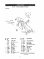
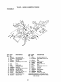
TILLER
-- MODEL
NUMBER
917.293300
HANDLES
1
\
29
%,
15
3O
11
\
\
31 \
KEY
PART
NO.
NO.
1
2
3
4
5
6
7
8
9
!0
12
13
14
15
16
t7
148583
141406
110673X
127254X
6712J
137119
110641X
711910D8
72010520
110646X
STD624003
81328
110741X
109313X
1!0702X
STD533710
t09229X
DESCRIPTION
KEY
NO.
Throttle, Control
Gdp, Handle
Grommet, Handle
Bar, Drive Conirol Assembly
Cap, Vinyl
Panel, Control
Bushing, Split
*Screw, Pan Head #t0-24
*Boll, 5116-18 x 2-1t2
Handle, Gdp
"Clip, Hairpin
Bolt, Shoulder
Handle, Shift
Grommet, Rubber
Rod, Shill
"Bolt, Carriage 3t8-!6 x 1 Gr. 5
Lock, Handle
\
PART
NO.
DESCRIPTION
18
19
20
21
22
23
STD54t437
19131611
109228X
150258
121145X
86777
24
25
26
27
28
29
30
31
9484R
73970500
110675X
STD541025
STD55!125
STD541462
104164X
150696
*Nut, Centedock 3/8-16
Washer 13]32xl xll Ga
Lever,Lock, Handle
Handle, Assemble
Clip, Plastic, Cable
Screw, Hex, Washer Hd, Slotted
#t0-24 x 1t2
Clip
Loci,nut, Hex, Flange
Clutch, Cable
*Nut, Hex 1/4-20
"Washer, Lock 1/4
*Nut, Keps #10-24
Tie, Cable
Bolt, Pivot
' STANDARD HARDWARE- - PURCHASE LOCALLY
NOTE: All component dimensions given in tJ.S inches
1 inch =254 mm
22
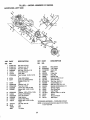
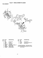
TILLER
MAINFRAME,
- - MODEL
HUMBER
917.293300
LEFT SIDE
38
\
31
21
\,
24
25
KEY
PART
NO.
NO.
1
2
3
4
5
6
7
STD541431
STD551137
STD541037
74930568
154734
110111X
STD532505
8
9
8700J
86777
10
11
12
I3
14
9484R
STD551125
STD541025
23230506
120938X
15
16
17
19
20
21
STD551031
145102
STD541031
12O00028
110653X
145216
23
104214X
5015J
128952
795R
DESCRIPTION
Nut, Keps 5/t6-18
*Washer, Lock 3/8
*Nut, Hex 3/8-16
Bolt, Hex 5/16-18 x 4-!!4
Screw Shift Lever
Lever, Shift
*Bolt, Carriage 1/'4-20 x 112Gr.
5
Plate, Shfft Indicator
Screw, Hex, Washer Heed,
Slotted #10-24 x 1/2
Clip
*Washer, Lock 114
*Nut, Hex 1/4-20
"Screw, Set, 5/16-18 x 3/8
Spacer, Split 0.327 x 0.42 x
2°68
*Washer 11132x 1!116 x 16 Ga.
Sheave, Transmission
*Nut, Hex 5116-18
Ring, Retainer
Guard, Pinch Point
Spacer, Split 0_327 x 0.42 x
1.688
Nut, Cap 5/16-18
Ttre
Rim
Tire Valve
KEY
PART
NO.
NO.
24
25
26
27
28
29
30
31
32
33
34
35
36
37
38
39
41
42
43
44
126875)(
STD624003
131159)(574
132801
104679X
12000032
159229
I02384X
I02141X
STD523710
102383X
74760524
102331X
130812
145822
140062
19111610
151004
69180
164173
DESCRIPTION
Rhtet'Drilled
*Clip, Hairpin
Guard, Belt
Belt, V
Pulley, Idler
Ring, Klip
Bracket, Idler
Bolt, Hex 5/16.16 x 12
Shaft, ldlerArm
*Bolt, Hex 3/8-16 x 1
Counterweight,L.Ho
Bolt,Hex 5/16-18 x 1 1/2
Bracket, Reinforcement,LH.
Sheave, Engine
Stud, Guard Belt
Cap, Plunger
Washer 11132x 1 x 10 Ga.
Spacer
Nut Lock #10-24
Bait Keeper
"STANDARDHARDWARE-- PURCHASELOCALLY
NOllE: All component
dimensions
givenin U.S. Inches.
1 inch= 25A mm
23
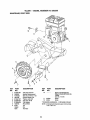
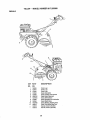
TILLER
MAINFRAME,
RIGHT
.. - MODEL
NUMBER
917.293300
SIDE
9
4
5
6
3
KEY
NO.
1
2
3
4
5
6
7
8
9
PART
NO.
STD54143t
102332X
7476O524
102t73X
STD551137
STD541037
STD624003
126875){
5015,t
128952
795R
DESCRIPTION
KEY
NO.
PART
NO.
lO
*Nut,Keps 5/16-18
Bracket,Reinforcement
Bolt,Hex 5116o18
x 1-1/2
CounterWeight,RH°
*Washer,Lock 3/8
*Nut, Hex 3/8-16
"Clip,Hairpin
Rivet,Drilled
_re
Rim
TireValve
11
12
_1535
94906
DESCRIPTION
Engine,(See Breakdown)
Briggs& Stratton(iP)ModefNo.
134402,
Type No,,1113-E1
Clamp
Screw
* STANDARDHARDWARE-. PURCHASELOCALLY
NOTE: All component
dimensions
givenin U.SJnches.
1 inch= 25°4mm
24
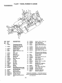
T6LLER - - MODEL
NUMBER
917.293300
TRANSMISSION
9
12
13
5t
KEY
PART
NO.
NO.
1
154354
2
150698
3
4
5
106211X
5020J
1370H
6
7
8
9
10
11
12
13
14
15
16
t8
19
20
137335
145101
4895H
154467
7392M
100371K
106160X
142145
8353J
12000039
154466
4358J
12000040
102114X
21
22
23
24
25
27
102115X
6BO3J
102111X
STD551143
STD541143
143009
DESCRIPTION
TransmissionAssembly
(Includes Key Nos.. 2-52)
Gearcase, LH. w/Bearing
(Includes Key No. 4)
Gasket, Gearcase
Beadng, Needle
Washer, Thrust 5/8 x 1.10 x
1/32
Pinion, Input
Shaft, Input
Bearing, Needle
"Washer,Seal
Ball, Steel
Spring, Shift, Fork
O-Ring
Arm, Shift
Fork, Shift
Ring, Klip
Shaft, Shift
Washer
Ring, Kltp
Gear, AssembLy,Reverse idler
(Includes Key Nos. 21 and 22)
Gear, Reverse Idler
Bearing, Needle
Shaft, Reverse Idler
*Washer, Lock 7/t6
*Nut, Hex 7!16-20
Bearing, Shaft, Ground Drive
L.H.
28
29
30
31
106390X
102134X
150737
143008
32
33
34
35
106388X
102121X
102112X
102t01X
36
154355
37
38
39
40
41
42
43
44
48
4422J
154356
105345X
t05346X
8358J
4220R
106146X
155236
150700
49
50
51
52
53
--
!32688
106147X
17720408
73220500
t22204X
6066J
Spacer 0.765 x 1.125 x 1.23
Chain #35-50 Pitch
Ground Shaft Assembly
Bearing, Shaft, Ground Ddve
R.Ho
Spacer 0.70 x 1,00 x 1.150
Sprocket and Gear Assembly
Shaft, Reduction (2nd)
Screw, Whiz, Lock 5/16-18 x 3!/2
Sprocket Assembly w!Bearing
(Includes Key Nos, 37 and 38)
Bearing, Needle
Sprocket, Tine
Gear, Cluster, Red 1st & 2nd
Gear, Reverse
Shaft, Reduction (1st)
Washer, Thrust
Spacer t.01 x 1.75 x 0.760
SealAsm. OII
Gearcase, R.H_w/Bearing
(Includes Key No, 8)
Shaft, "_ne
Chain, Roller #50-50 Pitch
Screw 1/4_20 x !/2
*Nut, Hex 5/16-18
Bearing Kit,'itne Shaft
Grease, Piasttlube #1
* STANDARD HARDWARE - - PURCHASE LOCALLY
NOTE: All component dimensions given tn U.S°lncheso
1 inch= 25.4 mm
25
TILLER = = MODEL NUMBER 917.293300
TINE SHIELD
14
11
18
24
24
KEY
PART
NO.
1
2
3
4
5
NO.
98000129
t61415x574
8393J
12000036
STD533107
6
7
8
9
10
11
t2
13
14
15
16
8394J
8392J
109230)(
124289X574
STD533110
STD541031
STD551t3t
72110510
124311X
161414X574
73510400
DESCRIPTION
KEY
NO.
Nut,Range 5/16_18
Shield,Side,OuterL. H.
Pin,Stake,Depth
Ring,Klfp
*Bolt,Carriage5/16-18x 3/4 Gr
5
Spring
Bracket,Latch
Spring,DepthStake
Shield,
_ne
*Bolt,Carriage5/16-t8 x I Gro5
*Nut,Hex 5/t6-18
*Washer,Lock 5/16
Bolt,Carriage5/16-18x t.1/4
Bracket,Shield"Tine
Shield,S_de,OuterR.H.
Nut,Hex 1/4-20
26
17
18
PART
NO.
162175
STD532512
DESCRIPTION
Nut,VYingForged5116-18
*Bolt,Cardage 1/4-20x 1-1/4
Gr. 5
19 t02701X
Grip
20 STD541037 *Nut,Hex 3/8-16
21 !02156X
Stake,Depth
74930632
Bolt,Hex 3/8-16x 2 23 4440J
Hinge
24 72140404
*Bolt,CarriageI/4-20 x 1/4
25 6712J
Cap,Vinyl
26 109227X
Pad,Idler
27 102695X574 Shield,Levering
28 120588X
Pin,Hinge
29 t24309X574 Shield,Side
30 73970500
Locknut0
Hex, Range
* STANDARDHARDWARE-- PURCHASELOCALLY
NOTE: Allcomponent
dimensions
givenin U.S. inches
I inch= 25A mm
TILLER
- - MODEL
NUMBER
917o293300
TINE ASSEMBLY
2
1
1
tl
9
\
KEY
PART
NO.
NO.
1
2
3
4
5
6
7
6
44593
132673
6554j
STD624008
132727
73610600
STD551137
74610616
DESCRIPTION
KEY
PART
NO.
NO.
9
10
tl
Tine, Outer, LH.
Pin, Shear
Tine, Inner, LHo
*Clip, Halrptn
Assembly, Hub and Plate, Loll.
Nut, Hex 316-24
*Washer, Lock 3/8
Bolt, Hex 3/8-24 x 1
4460J
132728
6555J
DESCRIPTION
Tins,Outer,R.H
Assembly,Huband Plate,Roll.
"line, Inner,Roll.
* STANDARD HARDWARE - - PURCHASE LOCALLY
NOTE: All component dimensions given In U.S. inches.
I inch = 25.4 turn
27
TILLER - =MODEL NUMBER 917.293300
DECALS
3
8
KEY
PART
NO.
NO.
1
2
3
4
5
6
7
8
9
10
11
---
158096
157991
157990
157984
137539
12043tX
102180X
147592
163094
120075X
162215
163158
163159
DESCRIPTION
Decat, Logo
Decal, Logo
Decal, Logo
Decal, Description
Decal, Caution, Drive Control
Decal, Hand Placement
Decal, Shift Indicator
Decal, Operation and Lubrication
Decal, Depth Stake
Decal, Warning, Rotating Tines
Decal, Tine Shield Wing Dom
Manual, Owner's (English)
Manual, Owner's (Spanish)
28
w=
ENGINE,
BRIGGS
& ST_ATTON
_" REQUIRES SPECIAL TOOLS
TO INSTALL, SEE REPAIR
INSTRUCTION
MANUAL
- - MODEL
_I
NUMBER
v
i = w_n_w_v_ww
134402,
TYPE
NO. 1113-E1
e
337_
13A
_562 ............
2_
429
957
601
_184
182
29
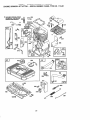
TILLER
- - MODEL
ENGINE, BRIGGS & STRATTON-
NUMBER
917.293300
.. MODEL NUMBER 134402, TYPE NO. 1113-E1
12
220
219 _
36
,35
20
524
30
32
,,
22
,L
l_r REQUIRES SPECLAL TOOLS
TO INSTALL SEE REPAIR
INSTRUCTION MANUAL,
24
456
30
623
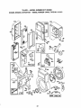
TRLLER - - MODEL NUMBER 917.293300
ENGINE,
BRIGGS
& STRATTON
- - MODEL
NUMBER
134402,
TYPE NO. 1"113-E1
124
%
6
0
_) 634
634A
137
111_:_
r_
116
i
ill
_
163
883
358 GASKET SET
...........................
.....
lo9_
....OVERHAUL
VALVE
GASKET SET
634 634A
977 CARBURETOR
GASKET SET
104
@oo,®
..........
, llll u,,_..2
31
127
t16
634A
634
121 CARBURETOR KIT
TILLER .,- MODEL NUMBER 917.293300
ENGINE, BRIGGS & STRATTON - - MODEL NUMBER 134402, TYPE NO. 1113-E1
159
284
284
%
163
11
335
23
3O4
_305
73
843A
455
32
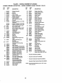
TILLER - - MODEL NUMBER 917.293300
ENGINE,
KEY
NO.
BRIGGS
PART
NO.
1
2
3
5
7
8
9
10
1i
t2
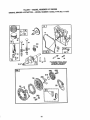
495133
399268
299819
214040
272157
495774
27549
94621
66578
270080
13
13A
14
15
270125
270126
94221
94915
94679
94916
I6
18
19
20
21
21A
492088
94388
494044
495660
294606
281658
399195
94980
22A
23
24
25
26
27
28
29
3O
32
34
94917
399673
_698
393819
393820
393821
393822
399067
399014
399015
399016
26026
298909
298908
299430
390459
225183
94699
211119
261044
& STRATTON
- - MODEL
DESCRIPTION
_t
NUMBER
KEY
NO.
CylinderAssembSy
Bushing
Seal, Oil
Head, Cylinder
Gasket, Cylinder Head
BreathsrAssembly
Gasket, Breather
Screw, Breather Mounting
Grommet
Gasket, Crankcase, .O15" Thick
(Standard)
Gasket, Crankcase, .005" Thick
Gasket, Crankcase, o009"Thick
Screw, Cyiinder Head 2_5/16
Stud, Cylinder Head
Screw, Cylinder Head 2-15/32
Plug, Oil Drain, 114"Standard,
Square Head
Crankshaft
Crankshaft Gear Key
Cover, Crankcase
Bushing
Seal, Oil
Plug, OII Rll
Plug, Otl Fill (For High Oil Fill
Hole)
Screw, Crankcase Cover
Mounting
Stud, Hex Head,
Crankcase Cover Mounting
Rywheel
Key, Rywheel
PistonAssembly, Standard Size
PistonAssembly, .010" Oversize
Piston Assembly, °020" Oversize
Piston Assembly, ,030" Oversize
Rtng Set, Standard Size
Ring Set, ,010" Oversize
Ring Set, .020" Oversize
134402,
PART
NO.
35
36
37
40
45
46
51
52
53
54
55
56
260552
26478
222443
225257
260642
214726
272295
272585
94923
94706
497442
498144
58
280399
59
60
65
73
75
95
98
98A
396892
393152
94686
225176
495659
94098
398185
493280
104
108
111
116
_- _
224783
262820
---
121
124
125
127
130
131
133
134
137
498260
94920
498599
--223470
493556
398187
398188
---
TYPE
NO. 1113-E1
DESCRIPTION
"
*
*
*
*
*
*
Spring, Intake Valve
Spring, Exhaust Valve
Guard, Flywheel
Retainer,Spring
Tappet, Valve
Gear, Cam
Gasket, Carburetor
Gasket, Intake Port
Screw, Torx",Hex
Screw, Hex Head
Housing, Rewind Starter
Pulley, Starter
(includes Rewind Spring)
Rope, Starter
(Cut to Required Length)
Insert, Starter Handre
Handle, Rewind Starter
Screw, Starter Mounting
Screen, Rotating
Washer Kit
Screw, Round Head
Screw, Idle Adjusting
ScrewAssembly,
Speed Adjustment
Pin, Hinge (Sold in Kit Only)
Valve, Choke
Spring, Lever
Gasket, Sealing (Sold in Kil
Only)
Carburetor Kit
Screw, Torx_, Hex
Carburetor
Plug, Welch
Valve, Throttle
Shaft, Throttle
Float, Carburetor
Valve, inlet (Includes Seat)
Gasket, Bowl {Sold in Kit Onty)
Ring Set, ,030'6Oversize
Lock, Piston Pin
*
Includedin Gasket Set (495661)
Pin, Piston, Standard Size
Pin, Piston, .005" Oversize
"
Includedin CarburetorKit (498260)
Rod, Connecting
Rod, Connecting,.02(7
Undersize Crankpin Bore
Dipper, Connecting Rod
Screw, Connecting Rod
Valve, Exhaust
Valve, Intake
*
Includedin CarburetorGasket Set (498261)
"
Includedin Valve Overhaul Gasket Set (498531)
NOTE: All componentdimensionsgiven in U,,S.inches
t inch= 25.4 mm
33
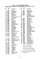
TRLLER - - MODEL
NUMBER
917.293300
ENGINE, BRIGGS & STRATTON - - MODEL NUMBER 134402, TYPE NO. 1113-E1
KEY
NO.
PART
NO,
141
159
163
164
t65
182
184
185
187
187A
188
200
201
209
2!9
220
222
227
230
232
265
267
284
300
304
305
306
307
498593
280871
272537
281247
94692
224669
94905
94010
298049
495218
94895
223886
262865
262283
494845
221551
494899
496082
94927
260585
221535
94906
94929
494562
497018
94786
224820
94680
308
332
333
335
337
224740
94877
397358
93414
802592
346 94896
347 493521
356 495135
495118
356A
358
363
373
383
429
445
455
456
459
515
524
528
535
552
562
592
495661
19069
94908
89838
281190
494511
225121
281503
281505
263073
271485
231818
492889
231079
94907
231978
DESCRIPTION
Shaft, Choke
Support, Air Cleaner
Gasket, Air Cleaner
Manifold, Intake
Nut, Wing
Bracket, Fue! Tank
Screw, Hex Head
Nut, Hex
Line, Fuel (tl" Long, Cut to Suit)
Line, Fuel, Molded
Screw, Shoulder
Guide, Air
Unk
Spring, Governor
Gear, Governor
Washer, Thrust
Bracket, Control
LeverAssembty, Governor
Washer, Governor Lever
Spdng, Link
Clamp, Casing
Screw, Slotted Hex
Screw, Hex Head
Muffler, Exhaust
Housing, Blower
Screw, Hex
Shfeld, Cylinder
Screw, Hex Head, Cylinder
Shield
Cover, Cylinder Head
Nut, Ry'whael
Armature, Magneto
Screw, Armature
Plug, Spark
(1-7/8" High, 48ram, Resistor
Type)
Screw, Hex Head, Seres
Switch, Stop
Wire, Stop (Armatureto Switch)
Wire, Stop (Stop Switch to
Ground)
Gasket Set
Puller, Flywheel
Nut, Hex
Wrench, Spark Plug
Cover, Spark Plug
Filter, Air
Cup, Flywheel
Retainer, Spring
Pawl, Ratchet
Spring, Frictton
Seal, Oil Fill
Tube, Breather
Filter,Air
Bushing, Governor Crank
Bolt, Governor Lever
Nut, Hex
KEY
NO.
PART
Nee
601
608
611
6t4
616
623
634
634A
635
642
663
676
741
832
843
843A
851
864
869
870
871
883
955
957
958
966
969
971
972
975
977
978
979
982
984
1036
1095
2500
----
DESCRIPTION
93053
93807
497830
494451
93306
495243
94943
--...
Clamp, Hose, Green
Clamp, Hose, Black
Starter, Rewind
Connector,Fuel Line
Pin, Cotter
Crank, Governor
Screw, Shoulder
Seat, Shaft (Sold in Kit Only)
Seal, Choke Shaft (Sold In Kit
Only)
66539
Elbow,Spark Plug
281188
Cover, Air Cleaner
93343
Screw, Sems
495074
DetlectorAssembly
262992
Gear, Timing
Uses:
94388 Key, Woodruff
494903
Guard, Muffler
280149
Sleeve, Lever
280643
Sleeve, Lever
493880
Terminal,Cable
494904
Flange, Muffler
211787
Seat, tntakeValve
263094
Seat, Exhaust Valve, Cobalfte"
262001
Guide, ExhaustValve
63709
Gulde, Intake Valve
272309
" Gasket, Exhaust
497610
Screw, Fuel Bowl, Standard
493869
Screw, Fuel Bowl, High Altitude
493988
Cap, FuelTank
494769
Valve, Shut-Off
494902
Base, Air Cleaner
94872
Screw, Hex Head
94727
Screw, Hax Head
495345
Tank, Fuel
493640
Bowl,Float
498261
Gasket Set, Carburetor
273326
* Gasket Cover
494807
Cover, Oil Gard'
94658
Screw, Oil Gard"Cover
224746
Bracket, Inri[catorLight
499348
Label Kit, Emfss_on
498531
Gasket Set, Valve Overhaul
134402-0113 Replacement Engine
495952
Replacement Shortblock
*
included in Gasket Set (495661)
*
Included in Carburetor Kit (498261)
"
Inctuded in Carburetor Gasket Set (490937)
*
Included in Valve Overhaul Gasket Set (498531)
NOTE: All component dimensions given in U,.S. inches
1 Inch = 25,,4 mm
34
35
For the repair or replacement parts you need
delivered directly to your home
Call 7 am - 7 pro, 7 days a week
1-800=306-PART
(1-800-366-7278)
Para ordenar piezas con entrega a
domicilio - 1-800-659-7084
For in-house major brand repair service
Call 24 hours a day, 7 days a week
1-800-4oREPAHR
(1-800-473-7274)
Para pedir servicio de reparaci6n a
domicilio - 1-800-676-5811
For the location of a Sears Parts and
Repair Center in your area
Call 24 hours a day, 7 days a week
1-800=488-1222
MIIN
For information on purchasing a Sears
Maintenance Agreement or to inquire
about an existing Agreement
Call 9 am - 5 pm, Monday-Saturday
1=800=827-6655
When requesting service or ordering
parts, always provide the following
information:
• Product Type
= Part Number
• Model Number , Part Description
Americas
163158
Rev. 7
2.17.98
TR
Repair Speciat_sts
Printed
in U.S.A,


![PLAS A O ]-OR](http://vs1.manualzilla.com/store/data/005852706_1-5db0b7ed584537f0e62af161fb124638-150x150.png)