1
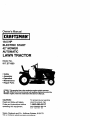
Owner's
Manual
ICRRFTSMRN'I
19.5 HP
ELECTRIC START
42" MOWER
AUTOMATIC
LAWN TRACTOR
Model No.
917.271820
•
•
•
•
•
Safety
Assembly
Operation
Maintenance
Repair Parts
This product has a low emission engine which operates
differently from previously built engines. Before you start the
engine, read end understand this Owner's Manual.
CAUTION:
For answers to your questions
Read and follow all Safety
Rules and Instructions before
about this product, Call:
operating this equipment.
Sears Craftsman Help Line
5 am - 5 pro, Mon- Sat
1-800-659-5917
Sears, Roebuck and Co., Hoffman Estates, II 60179
Visit our Craftsmanwebsite:www.sears.corn/craftsman
Maintenance .......................................
19
Service and Adjustments .................... 23
Storage ...............................................
29
Troubleshooting ................................. 30
Repair Parts ........................................
34
Parts Ordering ..................... Sack Cover
Warranty ...............................................
2
Safety Rules .........................................
3
Product Specifications .......................... 6
Assembly ..............................................
8
Operation ............................................
12
Maintenance Schedule ...................... 19
LIMITED TWO YEAR WARRANTY
ON CRAFTSMAN
RIDING EQUIPMENT PARTS
For two (2) years from the date of purchase, if this Craftsman Riding Equipment is
maintained, lubricated and tuned up according to the instructions in the owner's
manual, Sears will repair or replace, free of charge, any parts found to be defective in
material or workmanship. Warranty service is available free of charge by taking your
Craftsman riding equipment to your nearest Sears Service Center. In-home warranty
service is available but a trip charge will apply. This warranty applies only while this
product is in the United States.
This Warranty does not cover:
• Expendable items which become worn during normal use, such as blades, spark
plugs, air cleaners, belts and oil filters.
• Tire replacement or repair caused by punctures from outside objects, such as nails,
thorns, stumps, or glass.
• Repairs necessary because of operator abuse, including but not limited to, damage
caused by towing objects beyond the capability of the dding equipment, impacting
objects that bend the frame or crankshaft, or over speeding the engine.
• Repairs necessary because of operator negligence, including but not limited to,
electdcal and mechanical damage caused by improper storage, failure to use the
proper grade and amount of engine oil, failure to keep the deck clear of flammable
debds, or the failure to maintain the equipment according to the instructions
contained in the owner's manual.
• Engine (fuel system) cleaning or repairs caused by fuel determined to be contaminated or oxidized (stale). In general, fuel should be used within thirty (30) days of its
purchase date,
• Riding equipment used for commercial or rental purposes.
LIMITED 90 DAY WARRANTY ON BATTERY
For ninety (90) days from date of purchase, if any battery included with this dding
equipment proves defective in matedal or workmanship and our testing determines
the battery will not hold a charge, Sears will replace the battery at no charge. Warranty
service is available free of charge by taking your Craftsman riding equipment to your
nearest Sears Service Center. In-home warranty service is available but a tdp charge
will apply. This warranty applies only while this product is in the United States.
TO LOCATE THE NEAREST SEARS SERVICE CENTER OR TO SCHEDULE INHOME WARRANTY SERVICE, SIMPLY CONTACT SEARS AT 1-800-4-MY-HOME
This Warranty gives you specific legal dghts, and you may also have other rights
which may vary from state to state.
Sears, Roebuck and Co., D/817 WA, Hoffman Estates, IL 60179
2
IMPORTANT: This cutting machine is capable of amputating hands and feet and
thro.wing,objects. Failure to observe the following safety instructions could result in
senous injury or death.
I. GENERAL OPERATION
II. SLOPE OPERATION
• Read, undemtand, and follow all
Slopes are a major factor related to Iossinstructions in the manual and on the
of-contrel and tipover accidents, which
machine before starting.
can result in severe injury or death. All
• Only allow responsible adults, who are
slopes require extra caution. If you
familiar with the instructions, to operate
cannot back up the slope or if you feel
the machine.
uneasy on it, do not mow it.
DO:
• Clear the area of objects such as
rocks, toys, wire, etc., which could be
• Mow up and down slopes, not across.
picked up and thrown by the blade.
• Remove obstacles such as rocks, tree
• Be sure the area is clear of other
limbs, etc.
people before mowing. Stop machine
• Watch for holes, ruts, or bumps.
if anyone enters the area.
Uneven terrain could overturn the
• Never carry passengers.
machine. Tall grass can hide ob• Do not mow in reverse unless absostacles.
lutely necessary. Always look down
• Use slow speed. Choose a low gear
and behind before and while backing.
so that you will not have to stop or shift
• Be aware of the mower discharge
while on the slope.
direction and do not point it at anyone.
• Follow the manufacturer's recommenDo not operate the mower without
dations for wheel weights or countereither the entire grass catcher or the
weights to improve stability.
guard in place.
• Use extra care with grass catchers or
• Slow down before turning.
other attachments. These can change
• Never leave a running machine
the stability of the machine.
unattended. Always tum off blades, set
• Keep all movement on the slopes slow
parking brake, stop engine, and
and gradual Do not make sudden
remove keys before dismounting.
changes in speed or direction.
•Tum off blades when not mowing.
• Avoid starting or stopping on a slope. If
• Stop engine before removing grass
tires lose traction, disengage the
catcher or unclogging chute.
blades and proceed slowly straight
• Mow only in daylight or good artificial
down the slope.
light.
DO NOT:
• Do not operate the machine while
• Do not turn on slopes unless necesunder the influence of alcohol or drugs.
sary, and then, turn slowly and gradu• Watch for traffic when operating near or
ally downhill, if possible.
crossing roadways.
• Do not mow near drop-offs, ditches, or
• Use extra care when loading or
embankments. The mower could
unloading the machine into a trailer or
suddenly
turn over if a wheel is over
truck.
the edge of a cliff or ditch, or if an edge
• Data indicates that operators, age 60
caves in.
years and above, are involved in a
• Do not mow on wet grass. Reduced
large percentage of riding mowertraction could cause sliding.
related injuries. These operators
• Do not try to stabilize the machine by
should evaluate their ability to operate
putting your foot on the ground.
the riding mower safely enough to
• Do not use grass catcher on steep
protect themselves and others from
slopes.
serious injury.
3
III.
CHILDREN
Tragic accidents can occur if the operator
is not alert to the presence of children.
Children are often attracted to the
machine and the mowing activity. Never
assume that children will remain where
you last saw them.
• Keep children out of the mowing area
and under the watchful care of another
responsible adutt.
• Be alert and turn machine off if children
enter the area.
• Before and when backing, look behind
and down for small children.
• Never carry children. They may fall off
and be seriously injured or interfere
with safe machine operation.
• Never allow children to operate the
machine.
• Use extra care when approaching blind
corners, shrubs, trees, or other objects
that may obscure vision.
IV. SERVICE
• Use extra care in handling gasoline
and other fuels. They are flammable
and vapors are explosive.
- Use only an approved container.
- Never remove gas cap or add fuel
with the engine running. Allow
engine to cool before refueling, Do
not smoke.
-Never refuel the machine indoors.
- Never store the machine or fuel
container inside where there is an
open flame, such as a water heater.
• Never run a machine inside a closed
area.
• Keep nuts and bolts, especially blade
attachment bolts, tight and keep
equipment in good condition.
• Never tamper with safety devices.
Check their proper operation regulady.
• Keep machine free of grass, leaves, or
other debds build-up. Clean oil or fuel
spillage. Allow machine to cool before
storing.
• Stop and inspect the equipment if you
strike an object. Repair, if necessary,
before restarting.
• Never make adjustments or repairs
with the engine running.
• Grass catcher components are subject
to wear, damage, and detedoretion,
which could expose moving parts or
allow objects to be thrown. Frequently
check components and replace with
manufacturers recommended parts,
when necessary.
• Mower blades are sharp and can cut.
Wrap the blade(s) or wear gloves, and
use extra caution when servicing them.
• Check brake operation frequently.
Adjust and service as required.
• Be sure the area is clear of other
•
people before mowing. Stop machine if
anyone enters the area.
•
• Never carry passengers or children
even with the blades off.
•
• Do not mow in reverse unless abso•
lutely necessary. Always look down
end behind before and while backing.
• Never carry children. They may fall off
•
and be seriously injuredor interfere
with safe machine operation.
• Keep children out of the mowing area
and under the watchful care of another
respnnsible adult.
4
Be ated and turn machine off if children
enter the area.
Before end when backing, look behind
and down for small children.
Mow up and down slopes (15 ° Max),
not across.
Remove obstacles such as rocks, tree
limbs, etc.
Watch for holes, ruts, or bumps.
Uneven terrain cou_ overturn the
machine. Tall grass can hide obstacles.
• Use slow speed. Choose a low gear so
that you will not have to stop or shift
while on the slope.
• Avoid starting or stopping on a slope. If
tires lose traction, disengage the
blades and proceed slowly straight
down the slope.
• If machine stops while going uphill,
disengage blades, shift into reverse
and back down slowly.
• Do not turn on slopes unless necessary, and then, turn slowly and gradually downhill, if possible.
CAUTION: Tow only the attachments
that are recommended by and comply
with specifications of the manufacturer of
your tractor. Usa common sense when
towing. Operate only at the lowest
possible speed when on a slope. Too
heavy of a load, while on a slope, is
dangerous. Tires can lose traction with
the ground and cause you to lose control
of your tractor.
_,WARNING:
Engine exhaust, some of
its constituents, and certain vehicle
components contain or emit chemicals
known to the State of California to cause
cancer and birth defects or other reproductive harm.
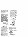
,_Look for this symbol to point out
important safety precautions. It means
CAUTIONI!! BECOMEALERT!!!
YOUR
SAFETY IS INVOLVED.
_WARNING:
Battery posts, terminals
and related accassories contain lead and
lead compounds, chemicals known to the
State of California to cause cancer and
birth defects or other reproductive harm.
Wash hands after handling.
_, CAUTION: In order to prevent
accidental starting when setting up,
transporting, adjusting or making repairs,
always disconnect spark plug wire and
place wire where it cannot contact spark
plug.
,_ CAUTION: Do not coast down a hill
in neutral, you may lose control of the
tractor.
5
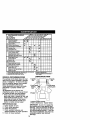
PRODUCT SPECIFICATIONS
GASOLINE
CAPACITY
ANDTYPE:
3.5 GALLONS
UNLEADED
REGULAR
OILTYPE
API-SF-SJ):
OIL CAPACITY:
SAE 30
(ABOVE 32°F)
SAE 5W-30
(BELOW 32°F)
3.0PINTS
SPARK PLUG:
GAP: .030")
VALVE
ADJUSTMENT
CHAMPION
RJ19LM OR Jt9LM
INTAKE:
.004"-.006"
EXHAUST: .007"-.009 _
GROUND
SPEED (MPH):
TIRE
PRESSURE:
FORWARD:
REVERSE:
FRONT:
REAR:
CHARGING
SYSTEM:
3 AMPS BA'I-rERY
5 AMPS HEADLIGHTS
BATTERY:
AMP/HR:
30
MIN. CCA: 240
CASE SIZE:U1R
BLADE BOLT
TORQUE:
27-35 FT. LBS
5.5
2.4
14 PSI
10 PSI
CONGRATULATIONS
on your purchase
of a new tractor. It has been designed,
engineered and manufactured to give
you the best possible dependability and
performance.
Should you experience any problem you
cannot easily remedy, please contact a
Sears or other qualified service center.
We have competent, well-trained technicians and the proper tools to service or
repair this tractor.
Please read and retain this manual. The
instructionswillenable you to assemble
and maintainyourtractorproperly.
Alwaysobservethe "SAFETY RULES".
REPAIR AGREEMENT
A Repair Agreementis available on this
product. Contactyournearest Sears
store for details.
CUSTOMER
RESPONSIBILITIES
• Read and observe the safety rules.
• Follow a regular schedule in maintaining, caring for and using your tractor.
• Follow the instructions under "Maintenance" and "Storage" sections of this
owner's manual.
_kWARNING: This tractor is equipped
with an internal combustion engine and
should not be used on or near any
unimproved forest-covered, brushcovered or grass-covered land unless the
engine's exhaust system is equipped with
a spark arrester meeting applicable local
or state laws (if any). If a spark arrestar is
used, it should be maintained in effective
working order by the operator.
In the state of California the above is
required by law (Section 4442 of the
Califomia Public Resources Code).
Other states may have similar laws.
Federal laws apply on federal lands. A
spark arrester for the muffler is available
through your nearest Sears service
center (See REPAIR PARTS section of
this manual).
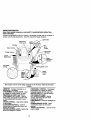
6
Steerin(
Swt_l:rePg
Adapter
Wheel
Steering
Sleeve
l
I
Extension
Shaft
teering
(1) Hex Bolt
3/8-16 x 1
Wheel
Inse_
©
(1) Lock
washer
3/8
(1) Hex Bolt
5/16-18 x 1-1/4
@
(1)
(1)Large Flat
Washer
Locknut
5/16-18
Seat
(1) Washer
17/32 x 1-3/16 x 12 Gauge
(1) Knob
Keys
Video Cassette
_
Shee
Slope
(1) Oil DrainTube
For FutureUse
7
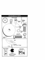
Your new tractor has been assembled at the factory with exception of those parts left
unassembled for shipping purposes. To ensure safe and proper operation of your
tractor all parts and hardware you assemble must be tightened securely. Use the
correct tools as necessary to insure proper tightness.
TOOLS
REQUIRED
FOR ASSEMBLY
8. Remove protective materiels from
tractor hood and gdll.
IMPORTANT: Check for and remove any
staples in skid that may puncture tire
where tractor is to roll off skid.
A socket wrench set will make assembly
easier. Standard wrench sizes you need
are listed below.
(1) 9/16" wrench
(1) Pliers
(2) 1/2" wrench
(1) Utility knife
(1) Tire pressure
ddve ratchet gauge
When dght or left hand is mentioned in
this manual, it means when you are in the
operating position (seated behind the
steedng wheel).
Steering
_ _.x
f______
_)
-_
TO REMOVETRACTOR
FROM
CARTON
UNPACK CARTON
1. Remove all accessible loose parts
and parts cartons from carton.
2. Cut, from top to bottom, along lines on
all four comers of carton, and lay
panels flat.
3. Check for any additional loose parts
or cartons and remove.
_
Washer
Large Flat
Steering j_'_
Wheel
_
Extension
Steedng Boot
_,_F
Shaft __--
Adapter
5/16 Locknut__'5/16
Hex Bolt
._--_.
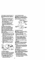
BEFORE REMOVING TRACTOR
FROM SKID
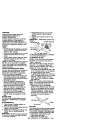
ATTACH STEERING WHEEL
Lower _
Steering
Shaft
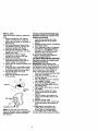
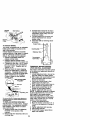
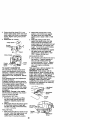
ASSEMBLE EXTENSION SHAFT AND
BOOT
1. Slide extension shaft onto lower
steedng shaft. Align mounting holes
in extension and lower shafts and
install 5/16 hex bolt and Iocknut.
Tighten securely.
2. Place tabs of steering boot over tab
slots in dash and push down to
_
\
, _!
;'-.
_
",
._
Tab
,, Slot
HOWTO SET UPYOURTRACTOR
CHECK BATrERY
1. Lift hood to raised position.
NOTE: If this battery is put into service
after month and year indicated on label
(label located between terminals) charge
battery for minimum of one hour at 6-10
amps. (See "BATTERY" in Maintenance
section of this manual for charging
instructions).
Secure.
INSTALL STEERING WHEEL
3. Position front wheels of the tractor so
they are pointing straight forward.
4. Remove steering wheel adapter from
steedng wheel and slide adapter onto
steering shaft extension.
5. Position steering wheel so cross bars
are horizontal (left to dght) and slide
inside boot and onto adapter.
6. Assemble large flat washer, 3/8 lock
washer, 3/8 hex bolt and tighten
securely.
7. Snap steering wheel Jnsed into center
of steering wheel.
Wheel
Bolt Insert
Lock Washer
8
INSTALL SEAT
Adjust seat before tightening adjustment
knob.
1. Remove adjustment knob and flat
washer securing seat to cardboard
packing and sat aside for assembly of
seat to tractor.
2. Pivot seat upward and remove from
the cardboard packing. Remove the
cardboard packing and discard.
3. Place seat on seat pan so head of
shoulder bolt is positioned over large
slotted hole in pan.
4. Push down on seat to engage
shoulder bolt in slot and pull seat
towards rear of tractor.
5. Pivot seat and pan forward and
assemble adjustment knob and flat
washer loosely, Do not tighten.
6. Lower seat into operating position and
sit in seat.
7. Slide seat until a comfortable position
is reached which allows you to press
clutch/brake pedal all the way down.
8. Get off seat without moving its
adjusted position.
8. Raise seat and tighten adjustment
knob securely.
Seat
Flat Washer
NOTE: You may now roll or drive your
tractor off the skid. Follow the appropriate
instruction below to remove the tractor
from the skid.
TO ROLLTRACTOR
OFF SKID (See
Operation section for location and
function of controls)
1. Press lift lever plunger and raise
attachment lift lever to its highest
position.
2. Release parking brake by depressing
clutch/brake pedal.
3. Place freewheel control in freewheeling position to disengage transmission (See TO TRANSPORT" in the
Operation section of this manual).
4. Roll tractor forward off skid.
5. Remove banding holding deflector
shield up against tractor.
TO DRIVETRACTOR
OFF SKID (See
Operation section for location and
function of controls)
_WARNING:
Before starting, read,
understand and follow all instructions in
the Operation section of this manual. Be
sure tractor is in a well-ventilated area.
Be sure the area in front of tractor is
clear of other people and objects.
1. Be sure all the above assembly steps
have been completed.
2. Check engine oil level and fill fuel
tank with gasoline.
3. Place freewheel control in "transmission engaged" position.
4. Sit on seat in operating position.
depress clutch/brake pedal and set
the parking brake.
5. Place motion control lever in neutral
(N) position.
6. Press lift lever plunger and raise
attachment lift lever to its highest
position.
7. Start the engine. After engine has
started, move throttle control to idle
position.
8. Release parking brake.
9. Slowly move the motion control lever
forward and slowly drive tractor off
skid.
10. Apply brake to stop tractor, set
parking brake and place motion
control lever in neutral position.
11 .Turn ignition key to "OFP' position.
Continue with the instructions that follow.
CHECKTIRE
PRESSURE
The tires on your tractor were overinflated
at the factory for shipping purposes.
Correct tire pressure is important for best
cutting performance.
• Reduce tire pressure to PSI shown in
"PRODUCT SPECIFICATIONS" section
of this manual.
CHECK DECK LEVELNESS
For best cutting results, mower housing
should be properly leveled. See "TO
LEVEL MOWER HOUSING" in the
Service and Adjustments section of this
manual
CHECK FOR PROPER POSITION OF
ALL BELTS
See the figures that are shown for
replacing motion and mower blade drive
belts in the Service and Adjustments
section of this manual. Verify that the
belts are routed correctly.
CHECK BRAKE SYSTEM
After you learn how to operate your
tractor, check to see that the brake is
property adjusted. See =TO ADJUST
BRAKE" in the Service and Adjustments
section of this manual.
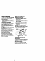
INSTALL
MULCHER
PLATE
(If previously removed)
1. Raise and hold deflector shield in
upright position.
2. Place front of mulcher plate over front
of mower deck opening and slide into
place, as shown.
3. Hook front latch into hole on front of
mower deck.
4. Hook rear latch into hole on back of
mower deck.
CAUTION: Do not remove deflector
shield from mower. Raise and hold shield
when attaching malcher prate and a,ow it
to rest on plate while in operation.
Deflector
Mulcher
Plate
Hooks
TO CONVERT TO BAGGING OR
DISCHARGING
Simply remove mulcher plate and stere in
a safe place. Your mower is now ready for
discharging or installation of optional
grass catcher accessory.
NOTE: It is not necessary to change
blades. The mulcher blades are designed for discharging and bagging also.
10
t#CHECKLIST
BEFORE YOU OPERATE AND ENJOY
YOUR N EW TRACTOR, WE WISH TO
ASSURE THAT YOU RECEIVE THE BEST
PERFORMANCE AND SATISFACTION
FROM THIS QUALITY PRODUCT.
PLEASE REVlEWTHE FOLLOWING
CHECKLIST:
,I All assembly instructions have been
completed.
,,/No remaining loose parts in carton.
,z Battery is properly prepared and
charged.
(Minimum 1 hour at 6 amps).
•/ Seat is adjusted comfortably and
tightened securely.
,/All tires are properly inflated. (For
shipping purposes, the tires were
overinflated at the factory).
,I Be sure mower deck is properly leveled
side-to-side/front-to-rear
for best cutting
results. (Tiros must be propedy inflated
for leveling).
,z Check mower and drive belts. Be sure
they are routed propedy around pulleys
and inside all belt keepers.
,/Check wiring. See that all connections
are still secure and wires are properly
clamped.
,/Before ddving tractor, be sure freewheel control is in ddve position.
WHILE LEARNING HOWTO USE YOUR
TRACTOR, PAY EXTRA ATTENTION TO
THE FOLLOWING IMPORTANT ITEMS:
,./Engine oil is at proper level.
,I Fuel tank is filled with fresh, clean,
regular unleaded gasoline.
,z' Become familiar with all controls - their
location and function. Operate them
before you start the engine.
,/Be sure brake system is in safe
operating condition.
4' It is important to purge the transmission
before operating your tractor for the first
time. Follow proper starting and
transmission purging instructions (See
"TO START ENGINE" and "PURGE
TRANSMISSION" in the Operation
section of this manual).
11
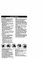
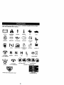
These symbols may appear on your tractor or in literature supplied with the product.
Learn and understand their meaning.
BATTERY
CAUTION OR
WARNING
REVERSE
FORWARD
FAST
SLOW
ENG,NEON
ENG,NEOFF
O'LFRESSURE
L,G.TSON
O%_MF
FUEL
CHOKE
MOWER HEIGHT
PARKING BRAKE
LOCKEO
N H
ATTACHMENT
CLUTCH ENGAGED
e_(_
REVERSE
NEUTRAL
ATTACHMENT
IGNITION
MOWER LIFT
L
HIGH
LOW
KEEP AREA CLEAR
CLUTCH DISENGAGED
UNLOCKED
PARKING BRAKE
SLOPE HAZARDS
(SEE SAFETY RULES SECTION)
FREEWHEEL
(Automat_ Modelson_)
DANGER, KEEPHANDSANDFEETAWAY
12
KNOWYOURTRACTOR
READ THIS OWNER'S
YOUR TRACTOR
MANUAL AND SAFETY RULES BEFORE OPERATING
Compare the illustrations with your tractor to familiadze yourself with the locations of
various controls and adjustments. Save this manual for future reference.
_t Switch
Attachment
Clutch Lever
Ignition
Switch
Ammeter
Lever
Choke Control
Plunger
Throttle Contml..,,.._
Lift Lever
Clutch/
BrakePedal
Height
Adjustment
Indicator
Free Wheel
Control
Brake Lever
Motion
Lever
Our tractors conform to the safety standards of the American National Standards
Institute.
AMMETER - Indicates charging (+) or
discharging (-) of battery.
ATTACHMENT CLUTCH LEVER - Used
to engage the mower blades, or other
attachments mounted to your tractor.
ATTACHMENT UFT LEVER - Used to
raise, lower, and adjust the mower deck
or other attachments mounted to your
tractor.
CHOKE CONTROL - Used when starting
a cold engine.
CLUTCH/BRAKE PEDAL - Used for
doclutching and braking the tractor and
starting the engine.
MOTION CONTROL LEVER - Selects the
speed and direction of tractor.
FREEWHEEL CONTROL * Disengages
transmission for pushing or slowly
towing the tractor with the engine off.
IGNITION SWITCH - Used for starting
and stopping the engine.
LIFT LEVER PLUNGER - Used to
release attachment lift lever when
changing its position.
LIGHT SWITCH - Turns the headlights on
and off.
PARKING BRAKE LEVER - Locks
clutch/brake pedal into the brake
position.
THROTTLE CONTROL - Used to control
engine speed.
13
(
The operation of any tractor can result in foreign objects thrown into the
eyes, which can result in severe eye damage. Always wear safety
glasses or eye shields while operating your tractor or performing any
adjustments or repairs. We recommend a wide vision safety mask over
spectacles or standard safety glasses.
I
I
HOWTO USEYOURTRACTOR
TO SET PARKING BRAKE
• Never use choke to stop engine.
IMPORTANT:
Leaving the ignition switch
in any position other than "OFF" will
Your tractor is equipped with an operator
cause the battery to be discharged,
presence sensing switch. When engine
(dead).
is running, any attempt by the operator to
NOTE: Under certain conditions when
Seave the seat without first setting the
tractor is standing idle with the engine
parking brake will shut off the engine.
running, hot engine exhaust gases may
1. Depress clutch/brake pedal into full
cause =browning" of grass. To eliminate
"BRAKE" position and hold.
this possibility, always stop engine when
2. Place parking brake lever in "ENstopping tractor on grass areas.
GAGED" position and release
• ILCAUTION: Always stop tractor
pressure from clutch/brake pedal.
completely, as described above, before
Pedal should remain in "BRAKE"
leaving the operator's position; to empty
position. Make sure parking brake
witl hold tractor secure.
grass catcher, etc.
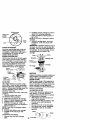
TO USE THROTTLE CONTROL
Choke
Attachment Clutch Lever
Position Always operate engine at full throttle.
• Operating engine at less than full
throttle reduces the battery charging
Control_
rate.
• Full throttle offers the best bagging and
Clutch/
mower performance.
Motion Control
Brake
TO USE CHOKE CONTROL
Brake
"D_sangaged'
Position
"Brake"
Position
"Eegage_
Position
STOPPING
MOWER BLADES • To stop mower blades,move attachment clutch lever to "DISENGAGED"
position.
GROUND DRIVE pedal
intodrive,
full "BRAKE"
i brake
o stop
ground
depress position.
clutch/
Move motion control lever to neutral (N)
position.
IMPORTANT: The motion control lever
does not retum to neutral (N) position
when the clutch/brake pedal is depressed.
ENGINE • Move throttle control to slow position.
NOTE: Failure to move throttle control to
slow position and allowing engine to idle
before stopping may cause engine to
"backfire".
• Turn ignition key to "OFF" position and
remove key. Always remove key when
leaving tractor to prevent unauthorized
USe.
Use choke control whenever you are
starting a cold engine. Do not use to start
a warm engine.
• To engage choke control, pull knob
out. Slowly push knob in to disengage.
TO MOVE FORWARD AND BACKWARD
The direction and speed of movement is
controlled by the motion control lever,
1. Start tractor with motion control lever in
neutral (N) position.
2. Release parking brake and clutch/
brake pedal.
3. Slowly move motion control lever to
desired position.
TO ADJUST MOWER CUTTING HEIGHT
The position of the attachment lift lever
determines the cutting height.
• Grasp lift lever.
• Press plunger with thumb and move
lever to desired position.
The cutting height range is approximately 1-1/2 to 4". The heights are
measured from the ground to the blade
tip with the engine not running.
14
These heights are approximate and may
vary depending upon soil conditions,
height of grass and types of grass being
mowed.
• The average lawn should be cut to
approximately 2-1/2 inches during the
cool season and to over 3 inches
during hot months. For healthier and
better looking lawns, mow often and
after moderate growth.
• For best cutting performance, grass
over 6 inches in height should be
mowed twice. Make the first cut
relatively high; the second to desired
height.
TO ADJUST GAUGE WHEELS
Gauge wheels are properly adjusted
when they are slightly off the ground
when mower is at the desired cutting
height in operating position. Gauge
wheels then keep the deck In proper
position to help prevent scalping in most
terrain conditions.
NOTE: Adjust gauge wheels with tractor
on a flat level surface.
1. Adjust mower to desired cutting height
(See "TO ADJUST MOWER CUTTING
HEIGHT" in the Operation section of
this manual).
2. With mower in desired height of cut
position, gauge wheels should be
assembled so they are slightly off the
ground. Install gauge wheel in
appropriate hole with shoulder bolt,
3/8 washer, and 3/8-16 Iocknut and
tighten securely.
3. Repeat for opposite side installing
gauge wheel in same adjustment
hole.
3/8-16
Jr;
Locknut_.
Gauge
Wheel
Mounting
Bracket
31
Gaugs Wheel "-'-''_'_
Bolt
TO OPERATE MOWER
Your tractor is equipped with an operator
presence sensing switch. Any attempt by
the operator to leave the seat with the
engine running and the attachment
clutch engaged will shut off the engine.
1. Select desired height of cut.
2. Stad mower blades by engaging
attachment clutch control.
TO STOP MOWER BLADES disengage attachment clutch control.
_I_CAUTION: Do not operate the mower
without either the entire grass catcher, on
mowers so equipped, or the deflector
shield in place.
AttachmentClutch Lever
"Engaged'Position
_-:_
/
J.
AttachemntLifi
C:"_;._)//V'I
LeverHigh
"_-_'__-r,--Position
_'ss_in
D_fl;dctor
TO OPERATE ON HILLS
_CAUTION:
Do not drive up or down
hills with slopes greater than 15 ° and do
not drive across any slope.
• Choose the slowest speed before
starting up or down hills.
• Avoid stopping or changing speed on
hills.
• If slowing is necessary, move throttle
control lever to slower position.
• If stopping is absolutely necessary,
push clutch/brake pedal quickly to
brake position and engage parking
brake.
• Move motion control lever to neutral
(N) position.
IMPORTANT: The motioncontrol =,ever
does not return to neutral (N) position
when the clutch/brake pedal is depressed.
• To restart movement, slowly release
parking brake and clutclVl0rake pedal.
• Slowly move motion control lever to
slowest setting.
• Make all turns slowly.
TO TRANSPORT
When pushing or towing your tractor, be
sure to disengage transmission by
placing freewheel control in freewheeling
position. Free wheel control is located at
the rear drewbar of tractor.
1. Raise attachment lift to highest
position with attachment lift control.
2. Pu!l freewheel control out and down
into the slot and release so it is held in
the disengaged position.
15
• Do not push or tow tractor at more than
two (2) MPH.
• To reengage transmission, reverse
above procedure.
NOTE: To protect hood from damage
when transporting your tractor on a truck
or a trailer, be sure hood is closed and
secured to tractor. Use an appropriate
means of tying hood to tractor (rope, cord,
etc.).
TOWING CARTS AND OTHER
ATTACHMENTS
Tow only the attachments that are
recommended by and comply with
specifications of the manufacturer of your
tractor, Use common sense when towing.
Too heavy of a load, white on a slope, is
dangerous. Tires can lose traction with
the ground and cause you to lose control
of your tractor.
BEFORE STAFITINGTHE
ENGINE
CHECK ENGINE OIL LEVEL
The engine in your tractor has been
shipped, from the factory, already filled
with summer weight oil.
1. Check engine oil with tractor on level
ground.
2. Remove oil fill cap/dipstick and wipe
clean, reinsert the dipstick and screw
cap tight, wait for a few seconds,
remove and read oil level. If necessary, add oil until "FULL" mark on
dipstick is reached. Do not overfill.
• For cold weather operation you should
change oil for easier stading (See "OIL
VISCOSITY CHART" in the Maintenance section of this manual).
• To change engine oil, see the Maintenance section in this manual.
ADD GASOUNE
• Fill fuel tank. Use fresh, clean, regular
unleaded gasoline with a minimum of
87 octane. (Use of leaded gasoline
will increase carbon and lead oxide
deposits and reduce valve life). Do not
mix oil with gasoline. Purchase fuel in
quantities that can be used within 30
days to assure fuel freshness.
IMPORTANT: When operating in
temperatures below 32°F(0°C), use fresh,
clean winter grade gasoline to be|p
insure good cold weather starting.
_llcW,A ,RN!NG,: Expe,dence indicats.sthat
onol eleneeo tuels tca,eo gasonol or
using ethanol or methanol) can attract
moisture which leads to separation and
formation of acids during storage. Acidic
gas can damage the fuel system of an
engine while in storage. To avoid engine
problems, the fuel system should be
emptied before storage of 30 days or
longer. Drain the gas tank, start the
engine and let it run until the fuel lines
and carburetor are empty. Use fresh fuel
next season. See Storage Instructions for
additional information. Never use engine
or carburetor cleaner products in the fuel
tank or permanent damage may occur.
_k CAUTION: Fill to bottom of Qas tank
filler neck. Do not overfill. Wip_ off any
spilled oil or fuel. Do not store, spill or
use gasoline near an open flame.
TO START ENGINE
When starlingthe engine for the firsttime or if
the engine has run out of fuel, it willtake
extra crankingtime to move fuel from the
tank to the engine.
1. Be sure freewheel control is in the
transmission engaged position.
2. Sit on seat in operating position,
depress clutcWbrake pedal and set
parking brake.
3. Place motion control lever in neutral
(N) position.
4. Move attachment clutch to =DISENGAGED" position.
5. Move throttle control to fast position
6. Pull choke control out for a cold
engine start attempt. For a warm
engine start attempt the choke control
may not be needed.
NOTE: Beforestarting,read the warm and
cold startingprocedures below.
7. Insert key into ignition and turn key
clockwise to "START" position and
release key as soon as engine starts.
Do not run starter continuously for
more than fifteen seconds per minute.
If the engine does not start after
several attempts, push choke control
in, wait a few minutes and try again. If
engine still does not start, pull the
choke control out and retry.
16
WARM WEATHER STARTING (50° F and
above)
8. When engine starts, slowly push
choke control in until the engine
begins to run smoothly. If the engine
starts to run roughly, pull the choke
control out slightly for a few seconds
and then continue to push the control
in slowly.
• The attachments and ground drive can
now be used. If the engine does not accept
the load, restartthe engine and allow it to
warm up for one minute usingthe choke
as described above.
COLD WEATHER STARTING (50° F and
below)
8. When engine starts, slowly push
choke control in until the engine
begins to run smoothly. Continue to
push the choke control in small steps
allowing the engine to accept small
changes in speed and load, until the
choke control is fully in. If the engine
starts to run roughly, pull the choke
control out slightly for a few seconds
and then continue to push the control
in slowly. This may require an engine
warm-up period from several seconds
to several minutes, depending on the
temperature.
AUTOMATIC TRANSMISSION WARM UP
Before driving the unit in cold weather,
the transmission should be warmed up as
follows:
1. Be sure the tractor is on level ground.
2. Place the motion control lever in
neutral. Release the parking brake
and let the clutch/brake slowly return
to operating position.
3. Allow one minute for transmission to
warm up. This can be done during the
engine warm up pedod.
• The attachments can be used during
the engine warm-up period after the
transmission has been warmed up and
may require the choke control be
pulled out slightly.
NOTE= If at a high altitude (above 3000
feet) or in cold temperatures (below 32 F)
the carburetor fuel mixture may need to
be adjusted for best engine performance.
See "TO ADJUST CARBURETOR" in the
Service and Adjustments section of this
manual.
PURGETRANSMISSION
_CABTION:
Never engage or disengage
freewheel lever while the engine is
running.
To ensure proper operation and performance, it is recommended that the
transmission be purged before operating
tractor for the first time. This procedure wil!
remove any trapped air inside the transmission which may have developed during
shipping of your tractor.
IMPORTANT= Should your transmission
require removal for service or replacement,
it should be purged after reinstallation
before operating the tractor.
1. Place tractor safely on level surface
with engine off and parking brake set.
2. Disengage transmission by placing
freewheel control in freewheeling
position (See "TO TRANSPORT" in
this section of manual).
3. Sitting in the tractor seat, start engine.
After the engine is running, move
throttle control to slow position. With
motion control lever in neutral (N)
position, slowly disengage clutch/
brake pedal.
4. Move motion control lever to full
forward position and hold for five (5)
seconds. Move lever to full reverse
position and hold for five (5) seconds.
Repeat this procedure three (3) times.
NOTE= During this procedure there will be
no movement of ddve wheels. The air is
being removed from hydraulic ddve
system.
5. Move motion control lever to neutral
(N) position. Shut- off engine and set
parking brake.
6. Engage transmission by placing
freewheel control in driving position
(See "TO TRANSPORT" in this section
of manual).
7. Sitting in the tractor seat, start engine.
After the engine is running, move
throttle control to half (1/2) speed. With
motion control lever in neutral (N)
position, slowly disengage clutch/
brake pedal.
8. Slowly move motion control lever
forward, after the tractor moves
approximately five (5) feet, slowly
move motion control lever to reverse
position. After the tractor moves
approximately five (5) feet retum the
motion control lever to the neutral (N)
position. Repeat this procedure with
the motion control lever three (3)
times.
Your tractor is now purged and now ready
for normal operation.
17
MOWINGTIPS
• Mower should be properlyleveled for
best mowingperformance. See "1"O
LEVEL MOWER HOUSING" in the
Service and Adjustmentssectionof this
manual.
• The left hand side of mower shouldbe
used for trimming.
• Drive so that clippingsare discharged
ontothe area that has been cut. Have
the cut area to the dghtof the tractor.
This will resultin a more even distribution of clippingsand more uniform
cutting.
• When mowinglarge areas, startby
turningto the rightso that clippingswill
dischargeaway from shrubs,fences,
driveways,etc. After one ortwo
rounds,mow in the oppositedirection
making left hand turnsuntil finished.
• If grass is extremelytall, it shouldbe
mowed twice to reduce load and
possiblefire hazard from dried clippings. Make firstcut relativelyhigh;the
secondto the desired height.
• Do not mow grass when it is wet. Wet
grass will plug mower and leave
undesirableclumps. Allow grassto dry
before mowing.
• Always operate engine at full throttle
when mowing to assure bettermowing
performanceand proper dischargeof
material. Regulate ground speed by
selectinga low enough gear to give the
mower cuttingperformanceas well as
the qualityof cut desired.
• When operatingattachments, select a
groundspeed that will suit the terrain
and give best performanceof the
attachmentbeing used.
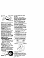
MULCHING MOWINGTIPS
IMPORTANT: For bestperformance,
keep mower housingfree of built-up
grass and trash. Clean after each use.
• The specialmulchingblade will recut
the grass clippingsmany times and
reducethem in size so that as they fall
ontothe lawn they willdisperse intothe
grass and not be noticed. Also, the
mulched grass will biodegradequickly
to providenutrientsfor the lawn.
Always mulchwith your highestengine
(blade) speed as this will providethe
best recuttingactionof the blades.
• Avoidcuttingyour lawn when it is wet.
Wet grasstends to form clumpsand
interfereswith the mulchingaction.
The besttime to mow your lawn is the
eady afternoon. At this timethe grass
has dried and the newly cut area will
not be exposedto the directsun.
• For best results,adjustthe mower
cuttingheightso that the mower cutsoff
onlythe top one-thirdof the grass
blades. For extremelyheavy mulching,
reduceyourwidthof cut on each pass
and mow slowly.
• Certain typesof grass and grass
conditionsmay requirethat an area be
mulcheda second timeto completely
hide the clippings. When doinga
secondcut, mow across or perpendicular to the firstcut path.
• Change your cuttingpatternfrom week
to week. Mow northto southone week
then changeto east to west the next
week. This will help preventmatting
and grainingof the lawn.
i
Max I/3"
f
q
•
18
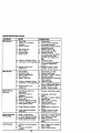
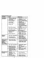
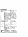
MAINTENANCE SCHEDULE
FILL IN OATES
AS YOU COMPLETE
REGULAR SERVICE
Check Brake Operation
check _r
inled_k
_ence
_
and
Systems
v'
v'
v',
i/,
v'
v'l
Lu_k:atlon Chart
Check Batlery Level
l/
v'
Clean Battmy ar_ Temdneis
CheCk Transaxle Co_ing
i/
V',
AdjustBledeBeltls)Tension
AdjustMotionDriveBeltls)Tenslo_
Check Engine Og Level
t/
i/
ChangeEngineOil
V',
=/2
Clean Air Filter
Clean Ak"Screen
i/
Inspect Muffler/Spark Alrester
Replace Oil Filter (If equip_c_l)
i/,
v' v'
v',
Clean Englee Cooling Fins
Ret0_ace Spark Plug
Ra_ace Air Filte: P_oet Cartrklge
Rapha:e Fue_ Filter
GENERAL RECOMMENDATIONS
The warrantyon thistractordoes notcover
itemsthathave been subjectedto operator
abuseor negligence.To receivefullvalue
from the warranty,operatormust maintain
tractoras instructedin this manual.
Some adjustmentswill need to be made
periodicallyto properlymaintainyour
tractor.
All adjustmentsin the Service and
Adjustmentssectionof this manualshould
be checkedat leastonce each season.
• Once a year you shouldreplacethe
spark plug,clean or replaceair filter,and
checkbladesand beltsfor wear. A new
spark plugand clean air filterassure
properair-fuelmixture and helpyour
engine run betterand last longer.
BEFORE EACH USE
1. Check engine oil level.
2. Check brake operation.
3. Check tire pressure.
4. Check operatorpresence and
interlocksystemsfor properoperation.
5. Check for loosefasteners.
19
LUBRICATION CHART
Zerk
_Front Wheel,.
Beanng
Zerk
- • Spindle
Zerk
BeedngZe_
_3General Purpose Grease
_Refer to Maintenance "Engine" Section
IMPORTANT: Do not oil or grease the
_ivot points which have special nylon
earings. Viscous lubricants will attract
dust and dirt that will shorten the life of
the self-lubricating bearings. If you feel
they must be lubncated, use only a dry,
powdered graphite type lubricant
sparingly,
TRACTOR
Always observe safety rules when
performing any maintenance.
BRAKE OPERATION
If tractor requires more than six (6) feet
stopping distance at high speed in
highest gear, then brake must be adjusted, (_ee "TO ADJUST BRAKE" in the
Service and Adjustments section of this
manual).
TIRES
• Maintain proper air pressure in all tires
(See "PRODUCT SPECIFICATIONS"
section of this manual).
• Keep tiros free of gasoline, oil, or insect
control chemicals which can harm
rubber.
• Avoid stumps, stones, deep ruts, sharp
objects andother hazards that may
cause tire damage.
NOTE: To seal tire punctures and prevent
flat tires due to slow leaks, tire sealant
may be purchased from your local parts
dealer. Tire sealant also prevents tire dry
rot and corrosion.
OPERATOR PRESENCE SYSTEM
Be sure operator presence and interlock
systems are working properly. If your
tractor does not function as described,
repair the problem immediately.
• The engine should not start unless the
clutch/brake pedal is fully depressed
and attachement clutch control is In the
disengaged position.
• When the engine is running, any
attempt by the operator to leave the
seat without first setting the parking
brake should shut off the engine.
• When the engine is running and the
attachment clutch is engaged, any
attempt by the operator to leave the
seat should shut off the engine.
• The attachment clutch should never
operate unless the operator is in the
seat.
BLADE CARE
For best results mower blades must be
kept sharp. Replace bent or damaged
blades.
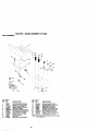
BLADE REMOVAL
1. Raise mower to highest position to
allow access to blades.
2. Remove hex bolt, lock washer and flat
washer securing blade.
3. Install new or resharpened blade with
trailing edge up towards deck as
shown.
IMPORTANT: To ensure proper assembly,
center hole in blade must align with star
on mandrel assembly.
4. Reassemble hex bolt, lock washer
and flat washer in exact order as
shown.
5. Tighten bolt securely (27-35 Ft. Lbs.
torque).
IMPORTANT:
Blade bolt is grade 8 heat
treated.
TraitincEdgeUp
Mandrel Assembly
Blade Center
Hole
Flat Washer.
Lock Washe
_'Hex
Bok
*A Grade 8 heat treated boltcan be identified
by six lineson the bolt head.
TO SHARPEN BLADE
NOTE; We do not recommend sharpenir_ blade - but if you do, be sure the
blade is balanced.
Care should be taken to keep the blade
balanced. An unbalanced blade will
cause excessive vibration and eventual
damage to mower and engine.
• The blade can be sharpened with a file
or on a grinding wheel. Do not attempt
to sharpen while on the mower.
• To check blade balance, you will need
a 5/8" diameter steel bolt, pin, or a cone
balancer. (When using a cone balancer, follow the instructions supplied
with balancer.)
NOTE: Do not use a nail for balancing
blade, The lobes of the center hole may
appear to be centered, but are not.
• Slide blade on to an unthreaded
portion of the steel bolt or pin and hold
the bolt or pin parallel with the ground.
If blade is balanced, it should remain in
a horizontal position. If either end of
the blade moves downward, sharpen
the heavy end until the blade is
balanced.
,/
BATTERY
Your tractor has a battery charging system
which is sufficient for normal use. However, periodic charging of the battery with
an automotive charger will extend its life.
• Keep battery and terminals clean.
• Keep battery bolts tight.
• Keep sma|l vent holes open.
20* Recharge at 6-10 amperes for 1 hour.
NOTE:
Theoriginal
equipment
battery
on
yourtractorismaintenance
free. Do not
S_E V_osr_Y
_ADES
attempt to open or remove caps or covers.
Adding or checking level of electrolyte is
_MFEAA_S _
_pATEO
_S_
_S_ _ C_
not necessary.
NOTE: Although multi-viscosity oils
TO CLEAN BATTERY AND TERMINALS
(5W30, 10W30 etc.) improve starting in
Corrosion and dirt on the battery and
cold weather, these multi-viscosity oils
terminals can cause the battery to "leak"
will result in increased oil consumption
power.
when used above 32°F. Check your
1. Remove terminal guard.
engine oil level more frequently to avoid
2. Disconnect BLACK battery cable first
possible engine damage from running
then RED battery cable and remove
low on oil.
battery from tractor.
Change the oil attar every 25 hours of
3. Rinse the battery with plain water and
operation or at least once a year if the
dry.
tractor is not used for 25 hours in one
4. Clean terminals and battery cable
year.
ends with wire brush until bright.
Check the crankcase oil level before
5. Coat terminals with grease or petrostarting the engine and after each eight
leum jelly.
(8) hours of operation. Tighten oil fill cap/
6. Reinstall battery (See "REPLACING
dipstick securely each time you check the
BATTERY" in the SERVICE AND
oil level.
ADJUSTMENTS section of this
TO CHANGE ENGINE OIL
manual).
Determine temperature range expected
V-BELTS
before oil change. All oil must meet API
Check V-belts for deterioration and wear
service classification SF-SJ.
after 100 hours of operation and replace
• Be sure tractor is on level surface.
if necessary. The belts are not adjustable.
• Oil will drain more freely when warm.
Replace belts if they begin to slip from
• Catch oil in a suitable container.
wear.
1. Remove oil fill cap/dipstick. Be careful
TRANSAXLE COOLING
not to allow dirt to enter the engine
The transmission fan and cooling fins
when changing oil.
should be kept clean to assure proper
2. Remove cap from end of drain valve
cooling.
and install the drain tube onto the
Do not attempt to clean fan or transmisfitting.
sion while engine is running or while the
3. Unlock drain valve by pushing inward
transmission is hot. To prevent possible
slightly and turning counterclockwise.
damage to seals, do not use high
4. To open, pull out on the drain valve.
pressure water or steam to clean
5. After oil has drained completely, close
transaxle.
and lock the drain valve by pushing
• Inspect cooling fan to be sure fan
inward and turning clockwise until the
blades are intact and clean.
pin is in the locked position as shown.
• Inspect cooling fins for dirt, grass
6. Remove the drain tube and replace
clippings and other materials. To
the cap onto to the end of the drain
prevent damage to seals, do not use
valve.
compressed air or high pressure
7.
Refill engine with oil through oil fill
sprayer to clean cooling fins.
dipstick tube. Pour slowly. Do not
TRANBAXLE PUMP FLUID
overfill. For approximate capacity see
The transaxle was sealed at the factory
PRODUCT SPECIFICATIONS
and fluid maintenance is not required for
section of this manual.
the life of the transaxle. Should the
8. Use gauge on oil fill cap/dipstick for
transaxle ever leak or require servicing,
checking level. Be sure dipstick cap is
contact your nearest authorized service
tightened securely for accurate
center/department.
reading. Keep oil at "FULL" line on
ENGINE
dipstick.
LUBRICATION
Only use high quality detergent oil rated
with API service classification SF-SJ.
Select the oi!'s SAE viscosity grade
according to your expected operating
21
temperature.
OilDrainValve
Locked/
Drain
Poslion_.::
Closed and
Cap "_
Tube
CLEAN AIR SCREEN
Air screen must be kept free of dirt and
chaff to prevent engine damage from
overheating. Clean with a wire brush or
compressed air to remove dirt and
stubborn dried gum fibers.
ENGINE COOUNG FINS
Remove any dust, dirt or oil from engine
cooling fins to prevent engine damage
from overheating. Air guide covers must
be removed. Remove side panels and
hood (See "TO REMOVE HOOD AND
GRILL ASSEMBLY" in the Service and
Adjustments section of this manual).
Top Air
Gukte Cover__
Engine
Coo_i_JF
Air Guide
Cover
(Both Sides)
AIR FILTER
2. Carefully remove cartridge to prevent
debris from entering carburetor.
3. Clean cartridge by tapping gently on
flat surface.
NOTE: If very dirty or damaged, replace
cartridge.
4. Reinstall cartridge plate, wing nuts,
precteaner, cover and secure with
knob(s).
IMPORTANT: Petroleum solvents, such as
kerosene, are not to be used to clean the
cartridge. They may cause deterioration of
the cartridge. Do not oil cartridge. Do not
use pressurized air to clean or dry
cartridge.
Kno!
Wing
Air Screen
e Plate
_Cartridge
MUFFLER
Inspect and replace corroded muffler and
spark arrester (if equipped) as it could
create a fire hazard and/or damage.
SPARK PLUGS
Replace spark plugs at the beginning of
each mowing season or after every 100
hours of operation, whichever occurs first.
Spark plug type and gap setting are
shown in "PRODUCT SPECIFICATIONS"
section of this manual.
Your engine will not run properly using a
dirty air filter. Clean the foam pre-cleaner
after every 25 hours of operation or every
season. Service paper cartridge every 100
hours of operation or every season,
IN-LINE FUEL FILTER
whichever occursfirst.
The fuel filter should be replaced once
Service air cleaner more often under dusty
each season. If fuel filter becomes
conditions.
slogged, obstructing fuel flow to carbure1. Remove knob(s) and cover.
tor, replacement is required.
TO SERVICE PRE-CLEANER
1. With engine cool, remove filter and
2. Slide foam pre-cleaner off cartridge.
plug fuel line sections.
3. Wash it in liquid detergent and water.
2. Place new fuel filter in position in fuel
4. Squeeze it dry in a clean cloth.
line with arrow pointing towards
5. Saturate it in engine oil. Wrap it in
carburetor.
clean, absorbent cloth and squeeze to
3. Be sure there are no fuel line leaks
remove excess oil.
and clamps are properly positioned.
NOTE: If very dirty or damaged, replace
4. Immediately wipe up any spilled
pre-cleaner.
gasoline.
6. Reinstall pre-cleaner over cartridge.
Clamp__
7. Reinstall cover and secure with
knob(s).
TO SERVICE CARTRIDGE
larnp
1. Remove wing nuts and cartridge
22 Fuel Filterf
\ ,Z_
plate.
CLEANING
We do not recommend using a garden
hose to clean your tractor unless the
electrical system, muffler, air filter and
carburetor are covered to keep water out.
Water in engine can result in a shortened
engine life.
of
all foreign
Clean
engine,matter.
batten/, seat, finish, etc.
Keep finished surfaces and wheels
free of all gasoline, oil, etc.
• Protect painted surfaces with automotive type wax.
i
_
AUTION: BEFORE PERFORMING ANY SERVICE OR ADJUSTMENTS:
1. Depress clutch/brake pedal fully and set parking brake.
2. Place motion control lever in neutral (N) position.
3. Place attachment clutch in "DISENGAGED" position.
4. Turn ignition key "OFF" and remove key.
5. Make sure the blades and all moving parts have completely stopped.
6. Disconnect spark plug wire from spark plug and place wire where it cannot
come in contact with plug.
TRACTOR
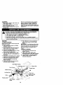
TO REMOVE MOWER
Mower will be easier to remove from the
right side of tractor.
1. Place attachment clutch in "DISENGAGED" position.
2. Move attachment lift lever forward to
lower mower to its lowest position.
3. Roll belt off engine pulley.
4. Remove small retainer spring, and lift
clutch spring off pulley bolt.
5. Remove large retainer spring, slide
collar off and push housing guide out
of bracket.
6. Disconnect anti-swaybar from chassis
bracket by removing retainer spring.
7. Disconnect suspension arms from
rear deck brackets by removing
retainer springs.
8. Disconnect front links from deck by
removing retainer springs.
9. Raise lift lever to raise suspension
arms. Slide mower out from under
tractor.
IMPORTANT: If an attachment other than
the mower deck is to be mounted on the
tractor, remove the front links and hook
the clutch spring Into square hole in
frame•
TO INSTALL MOWER
1. Raise attachment lift lever to its
highest position.
2. Slide mower under tractor with
discharge guard to right side of tractor.
3. Lower lift lever to its lowest position.
4. Install mower in reverse order of
removal instructions.
SmallRetainer Spring
\
Clutch
Retainer S
Anti-Sway
Retainer Springs
(Both Sides)
Housing
Large Retainer
Spdng
Bracket
23
TO LEVEL MOWER HOUSING
Adjust the mower while tractor is parked
on level ground or ddveway. Make sure
tires are propedy inflated (See "PRODUCT SPECIFICATIONS" section of this
manual). If tiros are over or
underinflated, you will not properly
adjust your mower.
SIDE-TO-SIDE ADJUSTMENT
• Raise mower to its highest position.
• At the midpoint of both sides of mower,
measure height from bottom edge of
mower to ground. Distance =A" on
both sides of mower should be the
same or within 1/4" of each other.
• If adjustment is necessary, make
adjustment on one side of mower only.
• To raise one side of mower, tighten lift
link adjustment nut on that side.
• To _ower one side ol mower, loosen lift
link adjustment nut on that side.
NOTE:Each full turn of adjustment nut
wilt change mower height about 1/8".
• Recheck measurements alter adjusting.
Bottomedge of
Bottomedge of
• If links are not equal in length, adjust
one link to same length as other link.
• To lower front of mower loosen nut "E"
on both front links an equal number of
turns.
• When distance "D" is 1/8" to 1/2" lower
at front than rear, tighten nuts "F"
against trunnion on both front links.
• To raise front of mower, loosen nut "F"
from trunnion on both front links.
Tighten nut =E" on both front links an
equal number of turns.
• When distance "D" is 1/8" to 1/2" lower
at front than rear, tighten nut =F" against
trunnion on both front links.
• Recheck side-to-side adjustment.
%_,_"
_.
oj/Mandrel
I"o"
Both FrontUnks Shouldbe Equal in Length
mower_round
Nut "F"_
(_G
Nut "E"
SuspensionArm
"Trsnnion f_
Front Links
LiftLinkAdjustmentNutI"
FRONT-TO-BACK ADJUSTMENT
IMPORTANT: Deck must be level side-to
side. If the following front-to-beck
adjustment is necessary, be sure to
adjust both front links equally so mower
will stay level side-to-side.
To obtain the best cutting results, the
mower housing should be adjusted so
that the front is approximately 1/8" to 1/2"
lower than the rear when the mower is in
its highest position.
Check adjustment on right side of tractor.
Measure distance =D" directly in front
and behind the mandrel at bottom edge
of mower housing as shown.
• Before makin 9 any necessary adjustments, check that both front links are
equal in length, Both links should be
approximately 10-3/8".
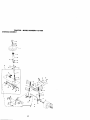
TO REPLACE MOWER BLADE DRIVE
BELT
The mower blade ddve belt may be
replaced without tools. Park the tractor on
level surface. Engage parking brake.
BELT REMOVAL 1. Remove mower from tractor (See "TO
REMOVE MOWER" in this section of
this manual).
2. Work belt off both mandrel pulleys and
idler pulleys.
3. Pull belt away from mower.
BELT INSTALLATION 4. Install new belt in reverse order of
removal.
5. Make sure belt is in all pulley grooves
and inside all belt guides.
6. Install mower in reverse order of
removal instructions.
24
Mandrel
Pull belt slack toward rear of tractor.
Carefully remove belt upwards from
transmission input pulley and over
cooling fan blades.
4. Pull belt toward front of tractor and
remove downward from around
engine pulley.
5. Install new belt by reversing above
procedure.
Idler Pulleys
3.
Mandrel
Pulley
TO ADJUST
BRAKE
EnginePulley _
Your tractor is equipped with an adjustable
brake system which is mounted on the
side of the transaxle.
If tractor requires more than six (6) feet
stopping distance at high speed in highest
gear on a level dry concrete or paved
surface, then brake must be adjusted.
1. Depress clutch/brake pedal and
engage parking brake.
2. Measure distance between brake
operating arm and nut "A" on brake rod.
3. If distance is other than 1-9/16", loosen
jam nut and tum nut "A" until distance
becomes 1-9/16". Retighten jam nut
against nut "A".
4. Road test tractor for proper stopping
distance as stated above. Readjust if
necessary. If stopping distance is still
greater than six (6) feet in highest gear,
further maintenance is necessary.
Contact a Sears or other qualified
service center.
WIth Parking Brake
o, e,o,sr
,ng
ii:i
Input Pulley -"'_@_
TRANSAXLE MOTION CONTROL
LEVER NEUTRAL ADJUSTMENT
The motion control lever has been preset
at the factory and adjustment should not
be necessary.
1. Loosen adjustment bolt in front of the
right rear wheel, and lightly tighten.
2. Start engine and move motion control
lever until tractor does not move
forward or backward.
3. Hold motion control lever in that
position and turn engine off.
4. While holding motion control lever in
place, loosen the adjustment bolt.
5. Move motion control lever to the
neutral (N) (lock gate) position.
6. Tighten adjustment bolt securely.
NOTE: If additional clearance is needed
to get to adjustment bolt, move mower
deck height to the lowest position.
After above adjustment is made, if the
tractor still creeps forward or backward
while motion control lever is in neutral
position, follow these steps:
t. Loosen the adjustment bolt.
2. Move the motion control lever 1/4 to
1/2 inch in the direction it is trying to
creep.
3. Tighten adjustment bolt securely.
4. Start engine and test.
5. If tractor still creeps, repeat above
steps until satisfied.
"Engaged"
Jam N,ut
UA"
r_
_
peratingArm
Do not touch this nut. If further brake adjustment is
necessary
contactyournearestauthorized
service
center/department
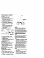
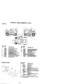
TO REPLACE MOTION DRIVE BELT
Park the tractor on level surface. Engage
parking brake. For assistance, there is a
belt installation guide decal on bottom
side of left footrest.
t. Remove mower (See "TO REMOVE
MOWER" in this section of this
manual.)
2. Remove belt from stationary idler and
clutching idler.
n2sl i1:1/_
25
MotionControl
,ever
Neutral Lock Gate
TO START ENGINE WITH A WEAK
BATTERY
_' CAUTION: Lead-ecid batteries
generate explosive gases. Keep sparks,
flame and smoking matedals away from
batteries. Always wear eye protection
when around batteries.
If your battery is too weak to start the
engine, it should be recharged. (See
"BATTERY" in the MAINTENANCE
section of this manual).
If "jumper cables" are used for emergency
starting, follow this procedure:
IMPORTANT: Your tractor is equipped
with a 12 volt negative grounded system.
The other vehical must also be a 12 volt
negative grounded system. Do not use
your tractor battery to start other vehicles.
TO A'I-rACH JUMPER CABLES 1. Connect each end of the RED cable to
the POSITIVE (+) terminal of each
battery, taking care not to short
against chassis.
2. Connect one end of the BLACK cable
to the NEGATIVE (-) terminal of fully
charged battery.
3. Connect the other end of the BLACK
cable to good CHASSIS GROUND,
away from fuel tank and battery.
AdjustmentBolt
TRANSMISSION REMOVAl/REPLACEMENT
Should your transmission require
removal for service or replacement, it
should be purged after reinstallation and
before operating the tractor. See "PURGE
TRANSMISSION" in the Operation
section of this manual.
TO ADJUST STEERING WHEEL
ALIGNMENT
if steering wheel crossbars are not
horizontal (left to right) when wheels are
positioned straight forward, remove
steering wheel and reassemble per
instructions in the Assembly section of
this manual.
FRONT WHEEL TOE-IN/CAMBER
The front wheel toe-in and camber are
not adjustable on your tractor. If damage
has occurred to affect the front wheel toein or camber, contact a Sears or other
qualified service center.
TO REMOVE WHEEL FOR REPAIRS
t. Block up axle securely.
2. Remove axle cover, retaining dng and
washers to allow wheel removal (rear
wheel contains a square key - Do not
lose).
3. Repair tire and reassemble.
NOTE: On rear wheels only: align
grooves in rear wheel hub and axle.
Insert square key.
4. Replace washers and snap retaining
dng securely in axle groove.
5. Replace axle cover.
NOTE: To seal tire punctures and prevent
flat tires due to slow leaks, tire sealant
may be pumhased from your local parts
dealer. Tire sealant also prevents tire dry
rot and corrosion.
Washers,_
RetainingRing ,_
_"lm=
TO REMOVE CABLES, REVERSE ORDER 1. BLACK cable first from chassis and
then from the fully charged battery.
2. RED cable last from both battedes.
"Positive" (+)
F"n° J
L.H.
c°v°r2
!
Square Key_r"'
(,RearWheel Only}_
"Negative" (-)
,_._P"
_mmw'_
26
REPLACING
BATTERY
CAUTION: Do not short batter/
terminals by allowing a wrench o_any
other object to contact both terminals at
the same time. Before connecting battery,
remove metal bracelets, wristwatch
bands, rings, etc.
I.
Positive terminal must be connected first
to prevent sparking from accidental
grounding.
1. Lift hood to raised position.
2. Remove terminal guard.
3. Disconnect BLACK battery cable then
RED battery cable and carefully
remove battery from tractor.
4. Install new battery with terminals in
same position as old battery.
5. Reinstall terminal guard.
6. First connect RED battery cable to
positive (+) baMery terminal with hex
bolt and keps nut as shown. Tighten
securely,
7. Connect BLACK grounding cable to
negative (-) battery terminal with
remaining hex bolt and keps nut.
Tighten securely
8. Close terminal access doors.
9. Close hood.
Terminal
Access
Door _
Terminal
Keps
i_:; :
/
Hood
.,f
:
•/
_
_
Headlight Wire
Connector
_Y/
ENGINE
Hex
"Bolt
Positive
Cable
(Black) Cable
Maintenance, repair, or replacement of
the emission control devices and systems, which are being done at the
customers expense, may be performed
by any non-read engine repair establishment or individual. Warranty repairs must
be performed by an authorized engine
manufacturer's service outlet.
TO ADJUST THROTTLE CONTROL
CABLE
The throttle control has been preset at the
factory and adjustment should not be
necessary. Check adjustment as described below before loosening cable. If
adjustment is necessary, proceed as
follows:
1. With engine not running, move throttle
control lever to fast position.
2. Check that swivel is against side of
quarter circle. If it is not, loosen cable
clamp screw and pull cable back until
swivel is against quarter circle.
Tighten cable clamp screw securely.
TO ADJUST CHOKE CONTROL
TO REPLACE HEADLIGHT BULB
1, Raise hood.
2, Pull bulb holder out of the hole in the
backside of the grill.
3. Replace bulb in holder and push bulb
holder securely back into the hole in
the backside of the grill.
4. Close hood.
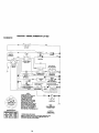
INTERLOCKS AND RELAYS
Loose or damaged wiring may cause your
tractor to run poorly, stop running, or
prevent it from starting.
• Check wiring. See electrical wiring
diagram in the Repair Parts section.
TO REPLACE FUSE
The choke control has been preset at the
factory and adjustment should not be
necessary. Check adjustment as described below before loosening cable. If
adjustment is necessary, proceed as
follows:
1. With engine not running, move choke
control (located on dash panel) to full
choke position.
2. Remove air cleaner cover, filter and
cartridge plate to expose carburetor
choke (see "AIR FILTER" in the
Maintenance section of this manual).
Replace with 20 amp automotive-type
plug-in fuse. The fuse holder is located
behind the dash.
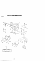
TO REMOVE HOOD AND GRILL
ASSEMBLY
1. Raise hood.
2. Unsnap headlight wire connector.
3. Stand in front of tractor. Grasp hood at
sides, tilt toward engine and lift off of
tractor.
4. To replace, reverse above procedure.
27
3. Choke should be closed. If it is not,
loosen casing clamp screw and move
choke cable until choke is completely
closed. Tighten casing clamp screw
securely.
4 Reassemble air cleaner.
Clamp
Quartor
Choke Clos_
Casing
TO ADJUST
_*=_i_i
CARBURETOR
The carburetor has been preset at the
factory and adjustment should not be
necessary. However, minor adjustment
may be required to compensate for
differences in fuel, temperature, altitude
or load.
If the carburetor does need adjustment,
proceed as follows:
In general, turning the mixture screw in
(clockwise) decreases the supply of fuel
to the engine giving a leaner fueVair
mixture. Turning the mixture screw out
(counterclockwise) increases the supply
of fuel to the engine giving a richer fuel/
air mixture.
IMPORTANT: Damage to the needles
and the seats in carburetor may result if
screw is turned in too tight.
PRELIMINARY SETTING -
2. With throttle control lever in slow
position, hold throttle lever against
idle speed screw and adjust idle
speed screw to obtain 1200 to 1400
RPM.
3. While still holding throttle lever
against idle speed screw, turn idle
mixture screw in (clockwise) until
engine begins to die and then turn out
(counterclockwise) until engine runs
rough. Turn screw to a point midway
between those two positions.
4. Continue to hold throttle lever against
idle speed screw and adjust idle
speed screw to obtain 900 to 1200
RPM. Release throttle lever.
ACCELERATION TEST 5. Move throttle control lever from slow to
fast position. If engine hesitates or
dies, turn idle mixture screw out
(counterclockwise) 1/8 turn. Repeat
test and continue to adjust, if necessary, until engine accelerates
smoothly.
High speed stop is factory adjusted. Do
not adjust - damage may result.
IMPORTANT: Never tamper with the
engine governor, which is factory set for
proper engine speed. Overspeeding the
engine above the factory high speed
setting can be dangerous. If you think the
engine-governed high speed needs
adjusting, contact a Sears or other
qualified service center, which has proper
equipment and expedence to make any
necessary adjustments.
Idle Speed
Screw
die Mixture
crew
trio
r
1. Be sure you have a clean air filter,
and the throttle control cable and
choke are adjusted properly (see
above).
2. With engine off turn idle mixture screw
in (clockwise) closing it finger tight
and then turn out (counterclockwise)
1-1/4 to 1-1/2 turns.
Idle Speed_
Screw_
FINAL SETTING 1. Start engine and allow to warm for five
minutes. Make final adjustments with
engine running and shift/motion
control lever in neutral (N) position.
Throttle
Lover _
28
__
_-------"-_ld_
Mixture
Screw
Immediately prepare your tractor for
storage at the end of the season or if the
tractor will not be used for 30 days or
more.
_l_ CAUTION: Never store the tractor with
gasoline in the tank inside a building
where fumes may reach an open flame or
spark. Allow the engine to cool before
storing in any enclosure.
TRACTOR
Remove mower from tractor for winter
storage. When mower is to be stored for
a period of time, clean it thoroughly,
remove all dirt, grease, leaves, etc. Store
in a clean, dry area.
1. Clean entire tractor (See "CLEANING"
in the Maintenance section of this
manual).
2. Inspect and replace belts, if necessary
(See belt replacement instructions in
the Service and Adjustments section
of this manual).
3. Lubricate as shown in the Maintenance section of this manual.
4. Be sure that all nuts, bolts and screws
are securely fastened. Inspect moving
parts for damage, breakage and wear.
Replace if necessary.
5. Touch up all rusted or chipped paint
surfaces; sand lightly before painting.
BA'R'ERY
Also, expedance indicates that alcohol
blended fuels (called gasohol or using
ethanol or methanol) can attract moisture
which leads to separation and formation
of acids during storage. Acidic gas can
damage the fuel system of and engine
while in storage.
1. Drain the fuel tank.
2. Start the engine and let it run until the
fuel lines and carburetor are empty.
• Never use engine or carburetor cleaner
products in the fuel tank or permanent
damage may occur.
• Use fresh fuel next season.
NOTE: Fuel stabilizer is an acceptable
altemative in minimizing the formation of
fuel gum deposits during storage. Add
stabilizer to gasoline in fuel tank or
storage container. Always follow the mix
ratio found on stabilizer container. Run
engine at least 10 minutes after adding
stabilizer to allow the stabilizer to reach
the carburetor. Do not drain the gas tank
and carburetor if using fuel stabilizer.
ENGINEOIL
Drain oil (with engine warm) and replace
with clean engine oil. (See "ENGINE" in
the Maintenance section of this manual).
CYLINDER(S)
1. Remove spark plug(s).
2. Pour one ounce of oil through spark
plug hole(s) into cylinder(s).
3. Tum ignition key to =START" position
for a few seconds to distribute oil.
4. Replace with new spark plug(s).
• Fully charge the battery for storage.
• After a period of time in storage, battery
may require recharging.
• To help prevent corrosion and power
leakage during long periods of storage,
battery cables should be disconnected
and battery cleaned thoroughly (see
'TO CLEAN BATTERY AND TERM!NALS" in the Maintenance section of
this manual).
• After cleaning, leave cables disconnected and place cables where they
cannot come in contact with battery
terminals.
• If battery is removed from tractor for
storage, do not store battery directly on
concrete or damp surfaces.
OTHER
• Do not store gasoline from one season
to another.
• Replace your gasoline can if your can
starts to rust. Rust and/or dirt in your
gasoline will cause problems.
• If possible, store your tractor indoors
and cover it to give protection from dust
and dirt.
• Cover your tractor with a suitable
protective cover that does not retain
moisture. Do not use plastic. Plastic
cannot breathe which allows condensation to form and will cause your
tractor to rust.
IMPORTANT:
Never cover tractor while
engine and exhaust areas are still warm.
ENGINE
FUEL SYSTEM
IMPORTANT: It is important to prevent
gum deposites from forming in essential
fuel system parts such as carburetor, fuel
hose, or tank during storage.
29
TROUBLESHOOTING
CHART
PROBLEM
CAUSE
Will not start
1. Out of fuel.
2. Engine not "CHOKED"
properly.
3. Engine flooded.
Hard to start
1.
2.
3.
4.
5.
1. Fill fuel tank.
2. See "TO START ENGINE"
in Operation section.
3. Wait several minutes before
attempting to start.
4. Bad spark plug.
4. Replace spark plug.
5. Dirty air filter.
5, Clean/raplece air filter.
6. Dirty fuel filter.
6. Replace fuel filter.
7. Water in fuel.
7. Drain fuel tank and carbure
tor, refill tank with fresh
gasoline and replace fuel
filter,
8. Loose or damaged wiring. B. Check all widng.
9. Carburetor out of adjustment 9. See "To Adjust Carburetor"
in Service Adjustments
section.
10.Engine valves out of
10.Contact a Sears or other
adjustment.
qualified service center.
Dirty air filter'
Bad spark plug.
Weak or dead battery.
Dirtyfuel filter.
Stale or dirtyfuel.
6. Loose or damaged wiring.
7. Carburetor out of adjustment
8. Engine valves out of
adjustment.
Engine will not
turn over
1. Clutch/brakepedal not
depressed
2. Attachment clutch is
engaged,
3. Weak or dead battery.
4. Blown fuse.
5. Corroded battery terminals.
6. Loose or damaged widng.
7. Faulty ignition switch.
Loss of power
1.
2.
3.
4.
5.
Cleaniraplace air filter.
Replace spark plug.
Recharge or replace battery.
Replace fuel filter.
Drain fuel tank and refill with
fresh gasoline.
6. Check all wiring.
?. See "To Adjust Carburetor" ir
Service Adjustments section.
3. Contact a Sears or other
qualified service center.
f. Depress clutch/brakepedal.
9. Faulty operator presence
switch(es).
2. Disengage attachment
clutch.
3. Recharge or replace battery.
4. Replace fuse.
5. Clean battery terminals.
3. Check all widng.
7. Check/replace ignition
switch.
8. Check/replace solenoid or
starter.
9. Contact a Sears or tother
qualified service center.
1.
2.
3.
4.
1.
2.
3.
4.
8. Faulty solenoid or starter,
Engine clicks but
•w not start
CORRECTION
Weak or dead battery.
Corroded battery terminals.
Loose or damaged widng.
Faulty solenoid or starter.
1. Cutting too much grass/too
fast,
2. Throttle in "CHOKE"
position.
30
Recharge or replace battery.
Clean battery terminals.
Check all widng.
Check/replace solenoid or
starter.
1. Set in "Higher Cut" position/
reduce speed.
2. Adjust throttle control,
TROUBLESHOOTING CHART
CAUSE
:PROBLEM
Loss_power
_ontinued)
3. Build-up of grass, leaves
and trash under mower.
4. Dirty air filter.
5. Low oil level/dirty oil.
6. Faulty spark plug.
7. Dirtyfuel fi'_er,
8. Stale or dirty fuel.
9. Water in fuel•
10.Spark plug wire loose.
11. Dirty engine air screen/fins.
12. Dirty/clogged muffler.
13. Loose or damaged widng.
14.Carburetor out of
adjustment.
15. Engine valves out of
Excessive
vibration
1. Worn, bent or looseblade•
2. Bent blade mandrel
3. Loose/damagedpart(s).
;ORRECTION
3, Clean underside of mower
housing•
4, Clean/replace air filter•
5. Check oil level/change oil.
6. Clean and ragap or change
spark plug.
7. Replace fuel filter.
8, Drain fuel tank and refill
with fresh gasoline.
9. Drain fuel tank and
carburetor, refill tank with
fresh gasoline and replace
fuel filter•
lO.Connect and tighten spark
plug wire.
11 .Clean engine air screen/
fins.
12.Clean/replace muffler.
13.Check all wiring.
14.See "To Adjust Carburetor"
in Service Adjustments
section•
15.Contact a Sears or other
qualified service center.
t, Replace blade•
Tighten blade bolt.
2. Replace blade mandrel
3. Tightenloosepart(s),
Replace damaged parts.
Enginecontlnues
to run when
operator leaves
seat with
attachment
clutch engaged
1. Faultyoperator-safety
presencecontrolsystem,
1. Check wiring,switchesand
connections,If not corrected
contacta Searsor other
qualifiad
service center.
Poor cut - uneven
1, Worn, bent or loose blade•
1. Replace blade. Tighten
blade bolt.
2. Level mower deck.
3. Clean underside of mower
housing.
4. Replace blade mandrel.
5. Clean around mandrels to
open vent holes.
2, Mower deck not level•
3, Buildup of grass, leaves,
and trash under mower.
4, Bent blade mandrel.
5, Clogged mower deck vent
from build-up of grass,
leaves, and trash around
mandrels.
Mower blades will
not rotate
1, Obstruction in clutch
mechanism•
2. Worn/damaged mower
drive belt.
3, Frozen idler pulley•
4, Frozen blade mandrel•
1. Remove obstruction.
2. Replace mower drive belt.
.• Replace
Replace idler
bladepulley.
mandrel.
TROUBLESHOOTING
PROBLEM
CHART
CAUSE
CORRECTION
Poor grass
discharge
1. Place throttle control in
=FAST" position.
2. Travel speed too fast.
2. Shift to slower speed.
3. Wet grass.
3, Allow grass to dry before
mowing.
4. Level mower deck.
4. Mower deck not level.
5. Low/uneven tire air pressur_ 5. Check tires for proper air
pressure.
6. Worn, bent or loose blade.
6. Replace/sharpen blade.
Tighten blade bolt.
7. Buildup of grass, leaves an_ 7. Clean underside of mower
trash under mower.
housing.
8. Mower drive belt worn.
8. Replace mower drive belt.
9. Blades improperly installed. 9. Reinstall blades sharp edge
down,
10. Improper blades used.
; 10. Replace with blades listed
in this manual.
11 ,Clean around mandrels to
11 .Clogged mower deck vent
holes from buildup of
open vent holes.
grass, leaves, and trash
around mandrels.
Headlight(s) not
working
(if so equipped)
1.
2.
3.
4.
1. Engine speed too slow.
Switch is "OFF".
Bulb(s) burned out.
Faulty light switch.
Loose or damaged wiring.
5. Blownfuse.
:Battery will not
charge
1. Bad battery cell(s).
2. Poor cable connections.
3. Faulty regulator
(if so equipped).
4. Faulty alternator.
Loss of drive
t
Engine "backfires"
whenturning
engine
"OFF"
1.
2.
3.
4.
Turn switch "ON".
Replace bulb(s).
Check/replace light switch.
Check wiring and connec
tions.
5. Replace fuse.
1. Replace battery.
2. Check/clean all connec
tions.
3. Replace regulator.
4. Replace alternator.
1. Freewheel control in
"disengaged" position.
2. Motion drive belt worn,
damaged, or broken.
3. Air trapped in transmission
during, shipment or
servicing.
1. Place freewheel controlin
"engaged" position.
2. Replace motiondrive belt.
1. Engine throttle control not
set at =SLOW"
position for 30 seconds
stopping engine,
1. Move throttle control to
"SLOW" position and allow
to idle for 30 seconds before
stopping engine.
32
3. Purge transmission.
TRACTOR -- MODEL NUMBER 917.271820
SCHEMATIC
BATTERY
AMMETER
(OPTIONAL)
NOTE
YOUR TRACTOR IS
EQUIPPED WITH A SPECIAL
ALTERNATOR SYSTEM.
THE LIGHTS ARE NOT
CONNECTED TO THE
BATTERY, BUT HAVE THEIR
OWN ELECTRICAL SOURCE.
BECAUSE OF THIS, THE
BRIGHTNESS OF TNE LIGHTS
WILL CHANGE WITH ENGINE
SPEED, AT IDLE THE LIGHTS
WILL DIM. AS THE ENGINE IS
SPEEDED UP, THE LIGHTS
WILL BECOME THEIR BRIGHTEST,
IGNmON
POSITION
HEADLIGHTS
F_
NON-REMOVABLE
CONNECTIONS
SWITCH
CIRCUIT
"MAKE-
OFF
M+G+A1
RUN_.IGHT
B+AI
RUN
B-_AI
START
B÷S÷A1
NONE
A2+L
NONE
NONE
REMOVABLE
CONNECTIONS
WIRING INSULATED CUPS
NOTE: IF WIRING INSULATED CLIPS WERE REMOVED FOR
SERVICING OF UNIT, THEY SHOULD BE REPLACED TO
PROPERLY SECURE YOUR WIRING.
33
ELECTRICAL
TRACTOR - - MODEL NUMBER 917.271820
34
TRACTOR - - MODEL NUMBER 917.271820
ELECTRICAL
KEY PART
NO. NO.
DESCRIP_ON
1
2
8
lO
11
12
16
21
22
24
25
26
27
28
29
3o
33
40
41
42
43
45
52
55
Battery
Bolt, Hex 1/4-20 x 3/4
Tray, Battery
Bolt, Btr Front 1/4-20 x 7-1/2
Holddown Battery Front Mount
Nut, Push Nylon Battery Front 1/4
Switch Interlock Push-in
Harness, Ught Socket (w/4152J)
Light Bulb
Cable, Battery
Cable, Battery
Fuse
Nut Keps Hex 1/4-20 Unc
Caole,Ground
Switch, Seat
Switch, Ignition
Key, Molded
Harness, igniUon
Bolt BIk Fin Hex 1/4-20 UNC x 1/2
Cover, Terminal
Solenoid
Ammeter Rectangolar 6 Amp
Protection Wire Loop (Hour Meter)
Screw Thdrol 5/16-18 x 1/2
163465
74760412
7603J
145211
150109
145769
153664
166182
4152
4799J
146148
175158
73510400
145491
1213(_X
175566
140403
170217
71110408
131563
175141
121433X
141940
1749(_608
NOTE: All component dimensions given in U.S. inches
1 inch = 25.4 mm
35
TRACTOR - - MODEL NUMBER 917.271820
CHASSIS AND ENCLOSURES
28
P
12
204
11
74
36
TRACTOR - - MODEL NUMBER 917.271820
CHASSIS AND ENCLOSURES
KEY
NO.
PART
NO.
1
2
3
5
9
10
11
12
13
17
18
20
23
25
26
28
29
30
31
37
38
51
52
53
54
55
57
58
60
64
74
142
143
144
145
159
206
207
208
212
--
169830
Chassis
169061
17060612
S_rew 3/8-16 x 3/4
155272
Bumper Hoo_Dnsh
168337X013 Dash
STD533710
Bott, Carrlege 3/8-16xl
155g_7
Panel, Dash, LH
145660
Clip Tthnsrman Grllle P/L
172107X010 Panel, Dash, RH
144963X558 HoodAssembly
126938X
Bumber Hood
1564,37
Plete M_ B_tteeJ Fu_ Tlu_
124(_8X
Bushing, Snap, Nylon, Fuel Line
19131312
Washer 13/32 x 13/16 x 12 Gauge
S'1_641437
LoCknut, Hex, with Insert 3/8-16 UNC
156725X558 Grille
155217XSS9 LenS, Gdlle
164919X6_8 Fender/Footrest
139976
Bracket,Fender/Support
174g(T_08
Screw, 131dro1.5/16-18 x 1/2 TYT
169834
Pivot Bracket Assembly, LH, Mower, Rear
73800400
Nut Lock W/Insert 1/4.20
UNC
19091416
Washer 9/32 X 7/8 X 16 Ga.
145201
Bracket Grille Plckofl LH
161464
SGrew, Hex Wshd #8-18 x 7/8
14520_
Bracket G_4e PP-,koffRH
S_7
Bolt FinHex 1/4 -20 UNC X,75
14(_47
Air Duct
72140606
Bolt Rdhd Sqnk 3/8-16 UNC x 3/4
154798
Dash Lower STLT
STD541437
Nut Crownkx_ 3/8-16 UNC
16r=867
Plete Reinforcement STLT
154966
Bracket Sw_yb_r Chasdis
154207
Bracket Footrest STLT
156524
Rod Rvot Chas_siHood
155123X428 Cupholder
170166
Bo_tShoulder 5/16-18Tl"
1767(To08
Straw *l'hdzol 5/16-18 x 1/2
17670608
Screw Thdrdi 3/8-16 x 1/2
165919
thsert, Lens
5479J
Plug Button
HOTE:
DESCRIPTION
Air component dimensions given In U.S. Indnes
1 inch = 25.4 rnm
37
GROUND
DRIVETRACTOR
"- MODELNUMBER
917.271820
38
TRACTOR -- MODEL NUMBER 917,271820
GROUND DRIVE
KEY
NO.
PART
NO.
t
......
8
10
14
15
16
19
21
22
24
25
26
27
28
29
30
32
34
35
36
37
38
39
40
41
42
47
48
49
50
61
52
53
55
56
57
59
61
63
63
165866
$313561210
10040400
7449(To44
STD541431
STD541437
149846
169498
73350600
106888X
ST05510_7
STITo61210
145204
71673
169592
74760512
155071
120183X
19211616
1572H
131494
7476_o44
4470J
165838
19131312
127783
154407
123205X
STD523715
STD541437
STD541431
1(_710X
105709X
STD633712
14(_94
169691
17060612
8883R
140186
DESCRiPTiON
KEY
NO.
PART
NO.
DE$CRtPTION
64
65
66
70
71
72
73
74
75
76
77
78
81
63
83
84
89
90
95
96
116
150
151
156
158
159
161
162
163
164
165
166
168
169
197
198
199
200
202
71170764
_/D551143
154779
134683
169183
19132012
169182
137057
121749)<
STD581075
123583X
121748X
165596
165711
19171216
169594
1648_)X428
124246X
170201
4497H
72110610
165850
19136310
16600_
165589
165494
72140406
73680400
74780416
19091010
165623
166880
165492
165580
16..°613
169593
16_612
72146ro08
72110612
BOll Hex 7/16-20 x 4 Gr. 6
Washer
Keaper Belt Engine Hydro
GoldeBeltRHEt',g_ne
Strap Torque Lh
Washer 13/32 x 1-1/4 x 12 Ga.
StrapTorque Rh
Spacer, Split
Washer 25/32x 1-114x 16Ga.
E-Pdng
Key, Square
Washer 25/32 x 1-5/8 x 16 Ga.
Shelf Asrn Cross
SpdngTorslon
Washer 17/32 x 3/4 x 16 Ga.
UnkTransax_e
Console, Shift
N_t Se_f-Th_ Wsh-hd 1/4 Z_c
Control Bypass
Retaine rS pdng 1" Zinc/Cad
Bolt Carr. 3/6-16 x 1.25
nushfng Bellcrenk Grd Ddve
Washer 13/32 x 2 x 10 Ga.
Washer Srrted 5/161D x 1.125
Bracket Shift Mount
Hub Tappered Flange Shift Lt
BoltRdhdSopkl/4.2Ox3/4Gr.5
NutCrownlockl/4*20Unc
Bolt Hex Fin 1/4-20 Unc x 1 Gr. 5
Washer 6/8 x .281 x 10 Ge
Bracket Pivot Lever
Screw 5116-18 x 6/8
Bolt Shoulder 6/16-18 x .561
Plate Fastening Lt
NylJner Snap-In
WasherNyllner
Bolt Shoulpar 5/16-18UNC
Bolt RDHD SQNK 5/16-18UNC x 1
Bo!tCarrSH3/8-16X1-1F_Gr.5
Transaxle (See Breakdown)
Hydro Gr 314.0510
Rod Shift Fender Adjust
pincher
1/SxlCAD
Washer Lock Hvy Helical
Bolt Hex FLGHO 3/16-18 GR.5
Nut Lock Hex W/Ins. 5/16-18 Uric
Nut Lock Hex WANsh 3/8-16 Unc
Knob, Deluxe 1/2-13
Rod, Brake Hydro
Nut, Hex 3am 3/8-16 Uric
Spdng, Brake Rod
Washer
Pin Cotter 1/8 x 3/4 CAD.
Rod, parking Brake
Cap, parking Brake
Bracket, Transaxle
BOlt Hex Hd 5/16-16 Uric x 3/4
Shaft, Foot Pedal
Bearing, Nylon
Washer
Pin, Roll
Pulley, idler, Flat
B_t
Spacer, S_1
Keaper, Belt Idler
Washer 13/32x13/16x12Ga.
Pulley. Idler, V=Groove
Bellcrank Clutch Grnd Dry STL
Retainer, Bett
Bolt
NulCrC_nlock 3/6-16UNC
Nut, Crownlock 5/16-18Unc
Link, Clutch
Spdng, Return, Clutch
Bolt Hex 3/8-16 x 1-1/4
V-Bert, Ground Drlve
Keaper, Center Span
Screw 318-16x3/4
Cover, Pedal
Pulley, Engine
NOTE:
39
All component dimensions given in U.S. inches
1 inch = 25.4 mm
TRACTOR - - MODEL NUMBER 917.271820
STEERING ASSEMBLY
_l_l
_
d':
40
TRACTOR - - MODEL NUMBER 917.271820
STEERING ASSEMBLY
KEY PART
NO. NO.
DESCRIPTION
I
2
3
4
5
6
7
8
9
10
11
13
15
17
18
19
22
23
25
26
27
28
29
30
32
36
37
38
39
40
41
42
43
44
46
47
51
54
62
63
65
66
67
68
79
80
8;2
85
Stsedng Wheel
Front Axle Assembly
Spindle Assembly, L.H.
Spindle Assembly, R.H.
Beadag, Race, Thrust, Hardened
Washer 25/32 x 1-5/8 x 16 Gauge
Washer 27/32 x 1-1/4 x 16 Gauge
Ring, KIIp
Beadag,SteedngColumn
"'
Lk_k, Or_
Washer, LOck
Spacer, Bearing, Front Axle
N',d, Hex5a4wje LOck
Shaft Assembly, Steedng
Washer, Thrust .515 x .750 x .033
Support, Shaft
Screw pax Wshhd Torx
Pitlm an Shaft Assembly
Bracket, Steering
Bushing, Link, Drag
Gear, Sector
Washer 13/32 x 7/_ x 16 Gauge
Screw 3/8-16 x 3/4
Rn
Rod, Tie
Bushing, Steedng
Screw 1-1"#10-32 x 5 x 3/8 Range
Insed, Steering Wheel
Washer 13/32 x 2-3/8 x 12 Gauge
Lock Nut Center 3/6-24 UNF
Adaptor, Steedng Whebl
Boot, Steedng Dash P/L Mtl B_k
W_ksher 25/32 x 1-1/4 x 16 Gauge
Extension Steedng NOn-Adjust
Cap, S_ndle
FL_ng, GraB,s6
Nut Lock Hx W/Ins 5/16-18 UNC
Bolt Rn Hex 5/16-18 UNC x 1-1/4
Y_t, S_eer_g Assembly, Sewlce
Bolt Fin Hex 3/8-16 uric. x I Gr. 5
Spacer Brace Axle
Beartng Arm Ptttman
Bdlt Rhnd Sqnk 3/8-16 x 2-1/4
Srace Axle
Washer 13/32 x 1-1/4 x 12 Ga
Bolt Hex Nylon 3/8-16 x 3/4
Bracket Susp Chsss_ Front
Fastener Christmas Tree
139768
154427
169840
16983_
6266H
121748X
19272016
12000029
3366R
169832
STD551137
136518
145212
156546
57079
160395
165857
165851
154406
126847X
136874
19131416
17060612
STD561210
130465
155099
152927
139769
19133812
$1_541537
100711L
145(To4X428
121749X
153720
121232X
6855M
73800500
7478_o20
16790_
74780616
160367
154404
72110618
169827
19132012
74950612
169835
133835
NOTE: All component dimensions given In U.S. Inches
1 ir,_n = 25.4 mm
41
TRACTOR - - MODEL NUMBER 917,271820
ENGINE
2
1_
IP
14
38
13 _10
i
12
32
31
33
39
33
29
OPTIONAL EQUIPMENT
Spark Arrester
42
TRACTOR - - MODEL NUMBER 917.271820
ENGINE
KEY PAITT
NO. NO.
DESCRIPTION
1
2
3
4
5
6
7
8
10
11
12
13
14
16
17
23
25
26
27
29
31
32
33
34
37
38
39
45
81
Control Throt Paddle
Screw Hex Thd Cut 1/4-20x5/8 T
Engine (See Breakdown) Bdggs Model No. 461707-0145-E3
Muffler Exhaust
Ext_ust Asm. Left
Exhaust Asm. Right
Clamp Tube Double Engine
Bolt 5/16 - 18 UNC X 3/4 W/Seres
Heat Shield Lt
Waster Lock HW, Hettcat 1¢4
Bolt Fin Hex 1/4-20 x 3/4
Gasket Muffler
Plug, Drain Oil Easy
Washer Locf< Ext Tooth 3/8
Screw TnGr06 3/8-16x1-1/2 Tytt
Shle_l Browning/Debris Guard
Cootr_ Choke
Nut Kap6 3/8-24 Unf
Screw TT #10-32 x 5 x 3/8 Flange
Arrestor Spark
Tank Fuel 3 50 Rear
Cap Fuel Guage STLT
Clamp Hose SIk
Spacer Pad
Line Fuel
Tube, Drain Oit Easy
P_d tdter 1,75 x ,75 )_ ,06
Screw 3/8-16 x SMGML
Nut, Kaps 1/4-20 Starter Nut
t7(_47
17720410
.......
149723
144069
144068
138129
171877
145,552
STD551125
STD522507
165287
148315
ST[_o51237
17490624
169837
145996
73920600
152927
137180
157103
161696
123487X
106G62X
8543R
148456
109227X
17060612
73510400
NOTE: All comportentdimensionsgiven(n U,S, Inches
1 inch= 25,4 mm
43
TRACTOR
"" MODELNUMBER
917.271820
sEAT AssEMBLY
KEY
NO.
KEY
NO.
2
3
67
8
9
10
11
12
pART
NO.
140551
71110616
t9131610
STD541437
1241 91X
I 7 0006 16
19131614
174894
166369
121246>(
r_u_r_°_..="_".C._=,_ 2 250 BIk ZI
Spdng ^.
_e-L*= P-'
X 1,5 SMGML
Screw
_.
.., -=---_w-.
13/32X1X
14Ge,
__a_._._ _=91 _k )
t_an
r.,
....
KnOb Sest
Bracket ptlt Moun',_ switch
DESGRtPTION
1/2
DEECR|PT|ON
_-_ F_n Hex 3/8-16ur_ X I
_i
Washer 13_2 X 3_4 X 10 GS
pART
NO.
~
17
I_^
_
Shoulder 5/I 8-Iu _n_'=
21
171852
._,=
=
_ex LOCkw/t_s 5/16"18
22
5T0641431
._.?__her 17_32 X 1-3/16 X 12 Gs'
24
19171912
was
er 5/16-18 X62
25
12T018X
BoltShoU d
"venlnU S inches
NOTE: Artcomponent clmens)OnS _
' '
1 _r_ch= 25.4 _m
44
TRACTOR - - MODEL NUMBER 917.271820
DECALS
7
2
2
\
4
20
22
14
14
13
KEY PART
NO. NO.
DESCRIPTION
1
2
3
4
5
6
7
9
11
13
14
Deca_ Fender Danger Sears
Decal Hood Side
Decal Hood Rh Cn_ftsm_n
Decal Hood Lh Craftsman
Decal Engine H/P
Decal Malnt Customer Sears Dom
Decal Replacement Srs
Decal Fender Cra_tsman Gold
Decal Fender STLTH Oper Inst E/S
Oeca_ V4:_dt Or Sch Tr_ctor E
Decal Dash Panel
156439
177253
171696
171697
176681
133644
171809
1632O4
156811
146046
177265
KEY
NO.
PART
NO.
DESCRIPTION
15
19
20
22
- - --- - -
16_G96
138047
172331
149516
169210
138311
165800X428
1_5799X428
177304
177305
Decal M0wer Ddve Schematic
Decal, Battery Diehard Sears
Decal Deck Mower EZ3
Decal Battery
Decal By Pass Lt Hydro
Decal Lift Haodle
Pad Footrest Lh STLT
Pad Foobest Rh STLT
Manuai,Owner's(Engllsh)
M_al,
OwneCs (Spa_sil)
KEY PART
NO. NO,
WHEELS & TIRES
4_10
45
DESCRIPTION
1
2
3
4
591 g2
65139
1G6222X
59904
5
6
7
s
g
lO
106732)(427
2"/8H
9040H
106108X427
1_':_82.X
7152,.I
11
104757X428
144334
NOTE:
All component dimensions _ven In U.S. Inches
1 inch = 25,4 mm
Valve Cap, Tire
Stem, Vsk, e
Tire, Front
Tube, Front Tire
(Not Provided, Service Item Only)
Rim, Front
Fitting, Grease (Front Wheal Orgy)
Bssdng, Flange (Froflt Wheel ONy)
Rim, Rear
Tire, Rear
Tude,Rear Tire
(Not Provided, Se_ce Item Only)
Cap, Axle
Sealant, "nro (10 oz, Tube)
TRACTOR - - MODEL NUMBER 917.271820
LIFT ASSEMBLY
2O
15
15
46
LIFT ASSEMBLY
TRACTOR . - MODEL NUMBER 917.271820
KEY PART
NO. NO.
I
2
3
4
5
6
7
8
11
12
13
15
16
17
18
19
2O
31
32
159460
159471
1G5767X
12O02O(_
19Ql1621
120183X
125631X
12_365X
139865
139666
STD_4(_8
173288
73350800
130171
139868
163552
169865
73540600
DESCRIPTION
Lilt Lever Inner Wire Asm.
Shaft Asm. Lift
Pin Groove
ERIng
Washar 21/32 x 1 x21 Ga.
Beadng Ny/ong
Gdp Handle Fluted
Button Plunger Read
Unk Asm Lift L.H.
Link Asm Lift R.H.
Retainer Spdng
Unk Front
Nut Jam Hex 1/2-13 Unc
Trunnion BIk Zinc
Nut Lock w/Wsh 1/2-13 Uric
Arm Suspension Mower
Retainer Spdng
Bearing, Pvt. Lilt. Tapered
Nut CrownlOCk 3/8.24
NOTE: All component d_mensIons g_ven in U.S, inches
1 inch = 25.4 rntn
47
TRACTOR - - MODEL NUMBER 917.271820
MOWER DECK
158
157 _ _,_
183 1_ s
67
159_
144
45
14S
34
21 22
18
48
TRACTOR - - MODEL NUMBER 917.271820
MOWER DECK
KEY PART
NO. NO.
1
2
3
165892
STt3533107
138017
4
5
6
8
9
10
11
13
165460
S_4008
13(J832
850857
STD551137
140296
134149
137645
14
15
16
18
19
20
21
22
23
24
25
26
27
28
29
30
31
32
33
34
35
36
37
40
44
45
46
48
49
50
51
52
53
54
55
56
126774
110485X
174493
72140505
132827
159770
s'rD541431
134753
131267
105304X
123713X
110452X
130968X428
19111016
131491
157722
129963
153535
137266
STD533717
133835
131494
19131316
STD541437
140088
STD624_03
1377"29
133944
174284
131340
S't'D541410
139888
131845
133943
155046
165723
KEY PART
NO. NO.
DESCRIPTION
Mower Hous;ng
Bolt
Bracket Assembly,Sway Bar,
Front
Bracket Sway Bar 38/42"
RetahlerSpdng
Arm, Buspenston, Rear
Bolt, Hex 3/8-24 x 1.26 Gr. 6
Washer, Lock
Washer, Hardened
Blade, Mulching
Shaft Assembly, Mandrel, Vented
(IncL Key Number 6)
Housing, Mandrel, Vented
Beadng, Ball, Maodrel
St_pper, Ventod Mower Deck
Bolt, Cardage 5/16-18 x 5/8
Bolt.Shoulder
Baffle, Vortex
Nut, Crownlock 5/16-18 UNC
Stiffener Bracket
Bracket, Denector
Cap, Sleeve
Spring, Torsion, Deflector
Nut, Push
Shield, Deflector
Washer 11/32 x 5/8 x 16 Ge.
Rod, Hinge
Screw Thdrol Rotting Wsh Hd
Washer, Space;'
Pulle=y,M,
Mandrel
NuL Top4(x;k, Flanged
Bo_t
Fastner, Christmas Tree
Pulley, Idler, Flat
Washer 13/32 x 13/16 x 16 Ga.
Nut,Crownleck3!8-16UNC
Guard, Mandrel, L,H.
Retainer
Screw, Thd. Roll 1/4-20 x 5/8
Washer, Hardened
Roller Assembly, Cam Follower
Bolt, Shoulder #10-24 Grade 5
Locknut
Bclt, Shoulder 6/16-18 UNC
Arm Assembly, pad, Brake
Washer, Hardened
Arm, Ioler
Spacer, Retainer
59
67
68
92
101
102
10_
104
105
106
111
112
113
114
115
116
117
118
119
121
129
130
131
142
143
144
145
146
147
148
149
150
151
152
153
154
155
156
157
158
159
.--
141043
149846
144859
STD541437
136420
71081010
19061216
STD551110
160793
2629J
155197
1551_
1706_514
7351(To00
7211(Too4
4896H
165746
73930600
19121414
143723
19131312
STC523710
$3"D533710
1658_0
157109
158634
165888
171977
131335
1_90_2
165898
19091216
169670
169676
16_674
169676
"t6967'_
169672
169669
17720410
STD593717
130794
169583
DESCRIPTION
Guard, Tuv Idler (94)
Knob Custom Ov_
V-Bs;t
Locknut, Hex W/Web 3/8-16 UNC
Cover Mulching 42" Black
Screw Truss Hd Phil1 0-24 x5/8
Wikqher#10
Washer Lock
Latch Asm Bagger
Nut Weld
Bracket Gauge, Wheel LH
Bracket, Gauge, Wheel RH
Screw 5/16-18
Nut, Hex Kep_ 5/16-18 UNC
Bolt, Cardage 5/16 UNC x !/2
Bolt, ShOulder
Wlleel, Gauge
Nut, Crown{ock 3/6-1
Washer 13/32 x 7/8 x 14 Ga.
Bracket
Washer 13/32 x 13/16 x 12 G8.
Bolt, Rn Hex 3/8-16 UNC x 1 Gr 5
Bdlt Rdhd Sqnk 3t6-10 UNC x 1
Arm SpdngBrake Mower
Bracket Arm Idler 42"
Keeper Belt 42- Clutch Cable
Pulley idler Flat
Bolt Carraige Idler
Spdng Extension
Spring Return Idle!
Retainer Spdng YellOw Zinc
W_:_er 9/32 x 3/4 x 16 Ga.
Bracket Clutch
Cable Clutch 42"
Washer flat 3/8" Type B
Spdng Retainer
Sprig Reto_flon Lever
spacer
RodClutch
Sotew Hex Thd Cut 1/4-20 x 5/6
B_t Rdhd Sqn 3/8-16 Uric x 1-3/4
Mandrel Assembly (Includes Key
Numbers 8-!0,12-15,31
and 3,?.)
Mower Deck, Comptete (Std de_order separately mulcher plate
components key n0s. 101-106)
NOTE: All componentdimensionsgivenIn U.S.inches
1 inch = 25.4 mm
dO
TRACTOR -- MODEL NUMBER 917.271820
HYDRO GEAR TRANSAXLE - - MODEL NUMBER 3140510
\
\
\
\
50
TRACTOR - - MODEL NUMBER 917,271820
HYDRO GEAR TRANSAXLE - - MODEL NUMBER 314-0510
KEY PART
NO. NO.
1
2
3
4
5
6
7
8
9
10
11
12
13
14
"_70351
170352
173253
170354
169898
170356
170356
170357
170358
170_59
170G60
169870
170361
169869
16
170362
17
18
19
23
24
27
28
29
30
31
170363
170_64
150771
170365
17G366
170367
170368
17G369
170_70
170371
170389
33
142991
34
35
36
37
38
39
40
41
42
43
44
170390
1_1
170_92
150792
150793
150809
170393
170394
170_95
170396
150797
45
46
47
48
49
50
51
52
170_97
170398
170999
170400
170401
170_
170403
170404
53
54
55
56
57
58
170405
170466
14297?
142978
150798
170407
KEY PART
NO. NO,
DESCRIPTION
Ma_n HousiP_, Assembly
Side Housing, Assembly
Center Section, Assembly
Swashptate,TRmton Maol'_ed
Btock- Assembly
Sealant 10.50z
Hex Flange Screw 1/4-20 X 1.25
Stud, 5/16-24 Hex Doubte End
Shaft, Input
Ring - Retaining
Spacer
Ring - Retaining
Seal. Lip .67 X 1.58 X .276
Ball Brg 17mm Id X 40ram Od X
12mrn
Hex Flange Head Screw 5/1624X0.75
Lip Seal 18 X 32 X 7
Arm, Control
Bearing, 30x52x13 Thrust
Check Plug Assembly, Washer
Shaft,Motor
Gear - Pinion, 13t
lOV4St Gear
Gear, 10t Jackshaft
60t Bull Gear
Steeve Bearing .75 X 1.575 X .625
SteeveBearing(Oulboard)
.75xl .750x.325
Washer, 3/4 td X 1-1/20d X .1S
Lip Seal Axte Seal
Shaft, Axte .75 X 11.30 (Key, R.H.)
Shaft, Axle .75 X 16.99 (Key, L.H.)
Miter Gear (Sp_ined)
Miter Gear 15t (0.5 Id)
Shaft
Ring, Spiral Retaining
Pin, Jeckshaft
Magnet, Ring
Spring, Bypass
Hydro Mtg Screw 3/8-24 X 2.5
Long
Filter
Base, Filter
Actuator, Bypass
Rod. Bypass/_ctuator
Arm, Bypass
Retolnlng Ring .250 External
Seal, Lip .741 X .260 X .250 TC
Flat Washer, 5_ Id X 1.00d X .05
Thk
ReteJ_gRk_g
Bearing, Center Block
Spdng - Helical Conlpresston
War=her
20w-50 Oil
Brake Yoke
_4
59
60
61
32
63
170408
142883
142881
142887
170410
64
_5
66
67
68
69
70
71
142892
170411
170412
170413
170414
170415
170416
170417
72
73
74
75
76
77
78
79
80
170418
142884
170419
170420
170421
170422
142969
142980
150778
81
32
170423
170424
83
84
85
86
07
88
90
9_
107
108
161132
170425
170426
170427
170424
170429
170430
170431
170432
170433
109
111
112
113
118
119
120
121
122
123
124
170434
170435
170436
170437
170438
170439
170440
170441
170442
170443
170444
125
12!_
127
900
170445
_70446
170447
168768
NOTE:
DESCRIPTION
Rotor, Brake
Brake Puck
Puck Rate
Brake Acbia6ug Pto
_
1/4`20x2 W/Patch,
SpadalF_
Bolt, 1/4-20 X 1 W/Patch
Spacer
Spdng, Brake Arm Bias
Sq. Hd. Bolt 5/16-24-PJbpad
Arm, Brake
Slotted Hex Nut 5/16-24
Co6er Pin 3/32 X 3/4
Co_ores_on
Spdng Brake AnUDrag
Washer, Ht .5 LD. X 10,D. X .032
Flat - Washar 11/32 I.D. X 7/80.D
Oil Seo1.625 X 1.0 X .25
Check Rug Assembly, .027,Washer
Stud, 5/16-24 FdcUon Pack
puck, .330 X 1.50 X .0975
Spring, Helical Comp
Spacer
Hex Lock Nut 5/16-24Un_f(Nyton
_nced)
Wedge, Frlctlcn Pack
Ctig, Washer .316xl ,50x,1046
(Rated)
Pin, Standard Headiess
Fitting, 5/16 Sae 5/32 Tube
Hose, Expansion Tank
Expansion Tank
Cap - Poppet Valve
Bolt, Serf Tapping 10-32 X 1/2
Puck, toner Wedge
Spring Cnp - Housing Thrust
Deflector
Washar,Motor Shaft
.711dx1.150dx.030thk
Rug, Sae #6
O-Ring .07 X .301 LD.
Shield, Vent
Bracket, Support Expansion Tank
SiliCOnSponge
Fan, 7 in.
Pulley
Flex Lock Nut 1/2_20 (Nylon h_sert)
Washer, BeJleville
BedKeepar
CentarSec_on-Ft_ter-Bypass
As_emoly
Filter Assembly
Ftm - Pultey Se_ce Ascembty
Seal - O-Rlng Kit
Transaxle C_ete
All component dimensions given in U.S. inches
1 inch = 25.4 mm
TRACTOR - - MODEL NUMBER 917.271820
BRIGGS & STRATTON ENGINE-MODEL NUMBER 461707, TYPE NUMBER 0145-E3
1125
19 G
634 e
552A
552
4040
1095 VALVE OVERHAUL
GASKET SET
741_
1de I_
220 _
1132
2911_
_
15 _
52
11019LABELKIT
I
1lO. OWNER'S
MANUAL]
lit REO_JIRE$S_CIAL 1OOLS
TO INSTALL SEE REPAIR
INSTRUCTION MANUAL.
TRACTOR
-- MODELNUMBER
917.271820
BRIGGS
& STRA'rTON
ENGINE-MODEL
NUMBER
461707,
TYPENUMBER
0145-E3
51 _
447 Ik, _
725
I
432_
222
392_)104_.
1138
_
240 _
304
7
573NN__
_
102
11 6
258 _
445
_
101
'k REQUIRES SPEC AL TOOLS
73
971I'
391
[ 1036 LABEL
KIT-EMISSION
102@
J
53
934_' 70
J
TRACTOR - - MODEL NUMBER 917.271520
BRIGGS & STRATTON ENGINE-MODEL NUMBER 461707, TYPE NUMBER 0145-E3
3o91
5101
802
513
783
1051 _'
y
697
803
797
544
801
358 GASKET SET
634
1770
163_
51A_
90569
_
54
TRACTOR - - MODEL NUMBER 917.271820
BRIGGS & STRATTON ENGINE-MOOEL NUMBER 461707,TYPE NUMBER 0145-E3
KEY
NO.
PART
NO.
1
2
3
4
5
5A
7
7A
8
498583
399265
391086
493304
691162
891163
271867
271868
495754
9
1O
10A
11
12
27803
690334
690366
280225
273390
271188
271189
13
15
16
19
20
23
24
25
27
28
28
94565
94239
690668
399264
291675
491180
222698
499180
499181
499182
499183
499184
499284
499186
499187
691299
498319
498320
29
29
32
33
498314
498541
691133
390420
34
35
36
40
41
42
45
48
47
48
50
51
51A
53
54
73
75
78
91
691302
65906
26828
221596
292260
494553
26t368
691161
393415
498542
213290
271412
270884
690321
93208
691438
225137
891134
693483
26
DESCRtPTtON
Cylinder Assembly
Bushing/Seal Kit
* Seal-Oil
Sump.Engins
Head-Cylinder #1
Head-Cylinder #2
-:_ Gasket-Cyl_ier Head #1
,:1: Gasket-C_linder Head #2
Bmainer Assembly (Cynnder
#t)
,_; Gasket-Breather
Screw (Breather Assembly)
Screw (Breather Cover)
Tube-Breather
• Gasket-Crankcase (.015"
Thick, Std.)
• Gasket-Crankcane (.005*
Thick)
* Gasket-Crankcase (.009"
Thick)
Screw (Cylinder Head)
Plug-Oil Drain
Crankshaft
Bushing
* Seat-oiL
Flywheel
Key-Flywheel
Piston Assembly (Standard)
Piston Assembly (.010 "O.S.)
P_ston Assembly (.020" O.S.)
Piston Assembly (.030' O.S.)
Ring Set, Piston (Standard)
Ring Set, Platen (.010 =O.S.)
Ring Set, Piston (.020 *O.B.)
Ring Set, P_Ston(.030 "O.S.)
Lock-Piston Pin
Pin Assembly. Piston Std.)
pin Assembly-piston (.005
O.S.)
Rod.Connecting (Standard)
Rod-Connecting (.020 U.S.)
Screw (Connecting Red)
Valve-Exhaust (inctude(a):
494553 Keeper-Valve (Ref.
NO. 42))
Valve-Intake
Spring-Valve (Intake)
Spr_lg-Valve (Exhaust)
Retainer-Valve Exhaust)
Retainer-Valve Exhaust)
Keeper.Valve
Tappet-Valve
Camshaft
Slinger-oil
Short Block
Manifold-intake
,(_ Gasket-intake
,_ Gaskta-intake
Screw (Carburetor)
Screw (Intake Manifold)
Screen-Rotatin 9
Washer(Flywheel)
Screw (Flywheet Fan)
Body Aasembly-Upper
KEY
NO.
PART
NO,
95
97
98
102
104
105
107
108
109
117
121
122
125
130
133
146
147
161
163
177
187
690716
693485
807923
693509
693506
692078
693482
693505
693498
693538
693500
491539
281411
893479
693504
893512
94196
693508
891401
271411
271170
499167
197
202
203
205
209
211
212
215
219
220
890364
890570
280997
690322
691273
261563
693985
690481
394348
690412
222
227
235
240
244
256
267
278
297
304
305
306
306A
491282
491297
224995
394358
230318
94930
690316
691365
94269
691390
690960
690414
690435
OESCRIPTION
O
O
£1
°
•
Screw (Thrott_ Valve)
Sheft-Throte
Kit-Idle Speed
Gasket-Carburetor Body
Pin-Float Hinge
Valve-Ftoat Nasdte
Body Assembly-Lower
Valve.Choke
Shaft-Choke
Jet-Main
Jet-Main (High Aititude)
Carburetor Kit
Spacer
Carburetor
Valve-Throttle
Flota-Carburetor
Key-Timing
Jet-Pilot
Baso-A_r C_eener
Gasket-Air Cleaner
Seal-O-Ring
Line-Fuel (Cut to Required
Length)
Screw (Back Pitaa)
Link-Mechanical Governor
Crank-Bell
Screw (Be_ Crank)
Spring-Governor
Spring-Governor
Link-Thro61e
Guide-Air
Gear-Governor
Washer.ThnJst (Governor
Gear)
Bracket-Control
Lever-Governor
Shletd-Fnel Spray
Filter-Fuel
Connector-Hose (Pulse Line)
Screw (Engine Sump)
Screw (Casing Clamp)
Washer (Governor Lever)
Nut-Wlng (Air Filter Retainer)
Housing-Blower
Screw (Btower Housing)
Shield-Cylinder
Shield-Cylinder
RPM Settings:Low Speed: 1900-2100
High Speed: 3000-3200
_D
_
+
Included in Gasket Set, Ref Number 358.
inctuded in Carburetor Kit, Ref Number
121.
Included in Value Overhaul Kit` Ref
Number 1095.
Included in Fuel Pump Kit. Ref Number
861
NOTE= All component dimensions given _nU,S.
inches 1 tnch= 25.4 mm
55
TRACTOR
- - MODELNUMBER
917.271820
BRIGGS
& STRATTON
ENGINE-MODEL
NUMBER
461707,TYPE
NUMBER
0145-E3
KEY
NO.
PART
NO.
307
309
310
311
332
333
334
337
358
383
386
391
392
404
423
425
432
433
434
435
441
445
447
449
474
482
510
513
523
525
527
535
544
552
552A
562
94930
497596
690323
497608
230674
394891
94731
802592
495868
89838
693490
693487
693491
690442
691100
94823
693492
693489
693493
693494
691176
394019
690297
94882
393474
93621
497606
398003
691385
690823
690423
272490
497603
690553
690552
690311
569
572
573
592
601
615
615A
616
634
634A
635
637
643
689
697
725
726
741
783
789
797
272645
690415
690764
92278
95162
690328
690317
491530
690657
271013
66538
693510
496700
690555
93585
280866
391362
691285
693059
695050
94010
DESCRIPTION
O+
O+
_+
0+
*
,
Screw (Cylinder Shield)
Motor-Starter
Bolt (Starter Motor)
Brush Set
Nut (Flywheel)
Armature-Magneto
Screw (Magneto Armature)
Plug-Spark
Gasket Sat
Wrench-Spark Plug
Gasket-Pump
Body-Pump
Spring-Pump Diaphragm
Washer (Governor Crank)
Screw (Air Cleaner Base)
Screw (Air Cleaner Cover)
Cap-Spring
Diaphragm-Fuel Pump
Cover-Diaphragm
Screw (Diaphragm Cover)
Bracket-Oil Fill
Filter-Air
Screw (Air Guide Cover)
Screw (Oil Fill Bracket)
Alternator
Screw (AIternalor)
Drive-Starter
Clutch-Drive
ulpsiDi
stick
Tube-Oil Fill
Clamp-Tube
Filter-Air
Armature-Starter
Bushing (Governor Crank)
Bushing (Governor Crank)
Bolt-Carltage (Governor
Lever)
Gasket-Base
Cover-Breather (Cylinder #2)
Plate-Back
Nut (Governor Lever)
Clamp-Hose
Retainer Governor Crank)
Rsta net-Governor Shaft
Crank-Governor
Seal-Governor Shaft
Washer-Foam
Boot-Spark Plug
Washer-Seal
,.
Retainer-Air Filter
Spring-Friction
Screw (Drive Cap)
Shlald-Heat
Gear-Ring
Gear-Timing
Gear-Starter
Wiring Hamess
Nut (Starter Terminal)
KEY
NO.
PART
NO.
797A
801
802
803
807
822
847
851
859
861
865
865A
868
868A
869
870
871
693167
Nut Starter Terminal)
394860
Cap-Drve
497607
Cap-End
691427
Housing-Starter
693511
Spacer
693497
Washer-Seal (Throttle Shaft)
495715
Dipstick/Tube Assembly
493880
Terminal-Cable
693488 O+ Diaphragm-Fuel Pump
693502
Klt-Fual Pump
691196
Cover-Air Guide
691197
Cover-Air Guide
497656
Seal-Valve
273312
Seal-Valve
261463
Seat-Valve (Intake)
262924
Seat*Valve (Exhaust)
261961
Bushing-Guide (Exhaust)
231218
Bushing-Guide (intake)
393456
Wire-Alternator
495901
Plate-Cover
393815
Hose-Vacuum (Cylinder-ToImpulse Pump)(Cut to
Required Length)
94627
Screw (Fan Retainer)
693513
Plug-Carburator
691207
Cover-Air Cleaner
690720
Screw (Upper Body To Lower
Body)
498157
Fan-Flywheel
691247
Retainer-Fan
496726
Label Kit
694979
Label Kit-Emission
263080
Ring-Retaining
273688
Owner's Manual
280860
* Seal-O-Ring
497605
Retainer-Brush
498047
Gasket Set-Valve Overhaul
691104
Screw (Cover Plate)
690353
Screw (Oil Slinger)
690329
Screw (Governor, Control
Rod)
690390
Washer (Governor, Control
ROd)
690330
Nut (Governor, Control Rod)
445777.0027-E1
Replacement Engine
877
881
918
934
955
968
971
1005
1006
1019
1036
1051
1058
1081
1090
1095
1125
1132
1136
1137
1138
----
DESCRIPTION
RPM Settings:Low Speed: 1900-2100
High Speed: 3000-3200
-O
:1:
+
Included
Included
121.
Included
Number
Included
86!
in Gasket Set, Ref Number 358.
in Carburetor Kit, Ref Number
in Value Overhaul Kit, Ref
1095.
in Fuel Pump Kit, Ref Number
NOTE: All compo_onant
dimensions given in U.S.
inches 1 inch = 25.4 mm
56
57
58
SUGGESTED
GUIDE
FOR SIGHTING
SLOPES
FOR SAFE OPERATION
ONLY RIDE UP AND DOWN HILL,
NOT ACROSS HILL
ut
QD
6
greater than 15 °) never across the face. Make turns gradually to prevent Upping or loss of control. Exercise extreme
Operate your Tractor up and down the face of slopes (not
caution when changing direction on slopes.
I
|
I
Get it fixed, at your home or ours!
For repair of major brand appliances in your own home...
no matter who made it, no matter who sold it!
1-800-4-MY-HOME
sMAnytirne,day or night
(1-800-469-4663)
www.sears.com
To bring in products such as vacuums,
lawn equipment and electronics for repair, call for
the location of your nearest Sears Parts & Repair Center.
1-800-488-1222
A.yt=r._.
dayor night
www.sears.corn
For the replacement parts, accessories and owner's manuals
that you need to do-it-yourself, call Sears PartsDirectSM!
1-800-366-PART
(1-800-366-7278)
6a.m.- 11p.m.CST,
7 daysa week
www.sears.com/partsdlrect
To purchase or inquire about a Sears Service Agreement:
1-800-827-6655
7 a.m.- 5 p.m.CST,Men.- Sat.
Para dadir servlciode reparacibna domicillo,
y para ordenar plezas con entrega a domlcillo:
1-888-SU-HOGAR
_
(1-888.784-6427)
[ HomeCentml
Au Canada pour service en fran_als:
1-877-LE-FOYER
_
(1-877-533-6937)
®J
OJ_l[of
Jtl_m_
I ,M _'ademark ofSeam, Roe_
and Co,
Mama Regtstrada/ _'- Marca de Fdbrtca de Sears, Roebuck and CO.
177304
Rev. 1 12.8.00 TR
Printed in U.S.A.