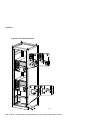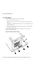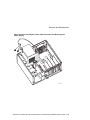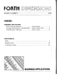
1
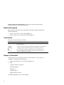
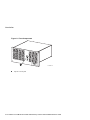
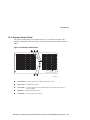
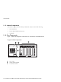
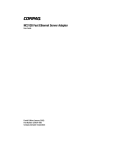
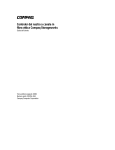
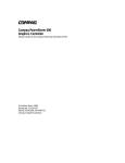
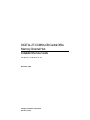
DIGITAL 2T-CCMHA-CB Central Office Memory Channel Hub Installation/Service Guide Part Number: EK-MCHCO-IN. A01 December 1998 Compaq Computer Corporation Houston, Texas December 1998 The information in this publication is subject to change without notice. COMPAQ COMPUTER CORPORATION SHALL NOT BE LIABLE FOR TECHNICAL OR EDITORIAL ERRORS OR OMISSIONS CONTAINED HEREIN, NOR FOR INCIDENTAL OR CONSEQUENTIAL DAMAGES RESULTING FROM THE FURNISHING, PERFORMANCE, OR USE OF THIS MATERIAL. THIS INFORMATION IS PROVIDED “AS IS” AND COMPAQ COMPUTER CORPORATION DISCLAIMS ANY WARRANTIES, EXPRESS, IMPLIED OR STATUTORY AND EXPRESSLY DISCLAIMS THE IMPLIED WARRANTIES OF MERCHANTABILITY, FITNESS FOR PARTICULAR PURPOSE, GOOD TITLE AND AGAINST INFRINGEMENT. This publication contains information protected by copyright. No part of this publication may be photocopied or reproduced in any form without prior written consent from Compaq Computer Corporation. FCC NOTICE: This equipment has been tested and found to comply with the limits for a Class A digital device, pursuant to Part 15 of FCC Rules. These limits are designed to provide reasonable protection against harmful interference when the equipment is operated in a commercial environment. This equipment generates, uses, and can radiate radio frequency energy and, if not installed and used in accordance with the instruction manual, may cause harmful interference to radio communications. Any changes or modifications made to this equipment may void the user’s authority to operate this equipment. Operation of this equipment in a residential area may cause interference in which case the user at his own expense will be required to take whatever measures may be required to correct the interference. 1998 Compaq Computer Corporation. All rights reserved. Printed in the U.S.A. The software described in this guide is furnished under a license agreement or nondisclosure agreement. The software may be used or copied only in accordance with the terms of the agreement. Compaq, Deskpro, Fastart, Compaq Insight Manager, Systempro, Systempro/LT, ProLiant, ROMPaq, QVision, SmartStart, NetFlex, QuickFind, PaqFax, ProSignia, registered in United States Patent and Trademark Office. Netelligent, Systempro/XL, SoftPaq, QuickBlank, QuickLock are trademarks and/or service marks of Compaq Computer Corporation. AlphaServer, DIGITAL, DIGITAL logo, , registered in United States Patent and Trademark Office. The following are third-party trademarks: Memory Channel is a trademark of Encore Computer Corporation. S3688 Table of Contents 1 Introduction 1.1 Overview .......................................................................................................... 1–1 1.2 Components and Controls ................................................................................. 1–1 1.2.1 Front Components ................................................................................... 1–1 1.2.2 Operator Control Panel............................................................................ 1–3 1.2.3 Internal Components ............................................................................... 1–4 1.2.4 Rear Components .................................................................................... 1–4 1.3 Specifications.................................................................................................... 1–5 2 Installation 2.1 General ............................................................................................................. 2–1 2.2 Site Preparation................................................................................................. 2–1 2.3 Unpacking the Shipment ................................................................................... 2–2 2.4 Installing the 2T-CCMHA-CB Central Office Memory Channel Hub................ 2–4 2.4.1 Determining the Installation Area............................................................ 2–4 2.4.2 Attaching the Slide Assemblies to the Cabinet Rails................................ 2–6 2.4.2.1 Attaching the Right Slide Assembly to the Cabinet Rails............... 2–6 2.4.2.2 Attaching the Left Slide Assembly to the Cabinet Rails................. 2–7 2.4.3 Attaching the Inner Races to the Tray ..................................................... 2–9 2.4.4 Mounting the Memory Channel Hub, Front Bezel, and Interlock Actuator Bracket on the Tray ..................................................................................... 2–10 2.4.5 Mounting the Chassis and Tray Assembly on the Slides ........................ 2–12 2.5 Installing the Interlock System....................................................................... 2–14 iii 3 Removal and Replacement 3.1 Introduction ...................................................................................................... 3–1 3.2 Top Cover......................................................................................................... 3–3 3.3 Power Supply.................................................................................................... 3–4 Figures Figure 1-1 Front Components ................................................................................. 1–2 Figure 1-2 Operator Control Panel .......................................................................... 1–3 Figure 1-3 Rear Components .................................................................................. 1–4 Figure 2-1 Installation Area and Rail-Hole Pattern (EIA Rail-Hole Pattern) ........... 2–5 Figure 2-2 Attaching the Slide Assemblies to the Cabinet Rails.............................. 2–7 Figure 2-3 Attaching the Inner Slide Races............................................................. 2–9 Figure 2-4 Mounting the Memory Channel Hub, Front Bezel, and Interlock Actuator Bracket on the Tray.............................................................................................2–11 Figure 2-5 Mounting the Chassis and Tray Assembly on the Slides .......................2–13 Figure 2-6 The Interlock System............................................................................2–16 Figure 3-1 Removing and Replacing the Top Cover ............................................... 3–3 Figure 3-2 Removing the Power Supply.................................................................. 3–4 Figure 3-3 Disconnecting the Power Cable Connector and Removing the Power Supply.................................................................................................................. 3–5 Tables Table 1-1 2T-CCMHA-CB Central Office Memory Channel Hub Specifications... 1–5 Table 2-1 Mounting Hardware and Component List ............................................... 2–3 iv Preface Overview This guide provides the information necessary to install the 2T-CCMHA-CB central office Memory Channel hub in a 48.26-cm (19-in.) NEBS 2000/ETSI-compliant cabinet with an EIA rail-hole pattern. It also provides information on removing and replacing the top cover and the power supply. Intended Audience This guide is intended for Compaq service personnel or qualified Self-maintenance customers who are familiar with installing computer systems, and for system managers and others who perform system management tasks. How to Use This Guide Read this guide before installing the 2T-CCMHA-CB central office Memory Channel hub. Before installation review the warranty. The terms of the warranty agreement with Compaq may require that a qualified Compaq Customer Services representative install the system. Contact your local Compaq representative if you have any questions. Organization This guide is organized as follows: Chapter 1, Introduction – Provides an overview of the 2T-CCMHA-CB central office Memory Channel hub and a description of the basic components and controls. Chapter 2, Installation – Provides site preparation, unpacking, and system installation information. v Chapter 3,.Removal and Replacement – Provides the removal and replacement procedures for the top cover and power supply. Related Documents Other documents related to the 2T-CCMHA-CB central office Memory Channel hub include the following: • Memory Channel User’s Guide (EK-PCIRM-UG) • Memory Channel Service Information (EK-PCIRM-SV) Conventions This guide uses the following conventions: Convention Meaning Note A note calls the reader’s attention to any item of information that may be of special importance. Caution A caution contains information essential to avoid damage to the equipment. Warning A warning contains information essential to the safety of personnel. Circled numbers provide a link between figures or examples and text. Italic type Italic type emphasizes important information, indicates variables, and indicates complete titles of manuals. Reader’s Comments Compaq welcomes your comments on this or any other manual. You can send your comments to Compaq in the following ways: • Internet electronic mail: [email protected] • Mail: Compaq Computer Corporation Information Design PKO3-2/21J 129 Parker Street Maynard, MA 01754-2199 For additional information call 1-800-344-4825. vi 1 Introduction 1.1 Overview The 2T-CCMHA-CB central office Memory Channel hub is used to share and route data between two AlphaServer 4100 central office systems. 1.2 Components and Controls System components and controls are located at the front, internally, and at the rear of the Memory Channel hub chassis. 1.2.1 Front Components Figure 1-1 shows the components located on the front of the Memory Channel hub chassis. DIGITAL 2T-CCMHA-CB Central Office Memory Channel Hub Installation/Service Guide 1–1 Introduction Figure 1-1 Front Components 1 DIGITAL Memory Cha Central nnel Hub 100/8 Office LJ-06497.AI7 Operator control panel 1–2 DIGITAL 2T-CCMHA-CB Central Office Memory Channel Hub Installation/Service Guide Introduction 1.2.2 Operator Control Panel The operator control panel (OCP), shown in Figure 1-2, is located on the front of the Memory Channel hub chassis and consists of an On/Off switch, a Reset button, and three LEDs. Figure 1-2 Operator Control Panel 3 4 5 DIGITAL Memory Channel Hub 100/8 Central Office 2 1 LJ-06498.AI7 On/Off switch — Powers the system secondary dc power on or off. Reset button — Initializes the system. Turbo LED — Lit when computer runs at rated microprocessor speed. Not lit when in non-turbo mode. Disk LED — Indicates disk drive activity. Power LED — Lit when power switch is On. DIGITAL 2T-CCMHA-CB Central Office Memory Channel Hub Installation/Service Guide 1–3 Introduction 1.2.3 Internal Components The internal components of the Memory Channel hub chassis consist of the following: • One motherboard • Four to eight CCMLA hub linecards • Cooling fan 1.2.4 Rear Components Figure 1-3 shows the components located on the rear of the Memory Channel hub chassis. Figure 1-3 Rear Components 3 1 2 7 6 5 4 3 2 1 0 LJ-06499.AI7 Power supply -48 Vdc power receptacle CCMLA linecard slots 1–4 DIGITAL 2T-CCMHA-CB Central Office Memory Channel Hub Installation/Service Guide Introduction 1.3 Specifications Table 1-1 contains the physical, environmental, and electrical specifications for the 2TCCMHA-CB central office Memory Channel hub. Table 1-1 2T-CCMHA-CB Central Office Memory Channel Hub Specifications Physical Characteristics Chassis Weight 13.6 kg (30 lb.) Length 40.64 cm (16 in.) Width 48.26 cm (19.0 in.) Height 17.78 cm (7.00 in.) Environmental Requirements Temperature range Operating 0°C to 40°C (32°F to 104°F) Non-Operating -20°C to 95°C (-4°F to 203°F) Temperature change rate 11°C/hr (20°F/hr) maximum Wet bulb temperature (maximum) 28°C (82°F) Dew point temperature (minimum) 2°C (36°F) Relative humidity 10% to 95% (noncondensing) Altitude 60 m to 3050 m (-200 ft to 10,000 ft) Electrical Requirements Nominal voltage -48 Vdc Operational voltage range -36 to -72 Vdc Input current (maximum) 1.25 A at -48 Vdc Input power 60 W DIGITAL 2T-CCMHA-CB Central Office Memory Channel Hub Installation/Service Guide 1–5 SES Template Word 7 Blank Page Fix by Peter LaQuerre 2 Installation 2.1 General This chapter covers the installation of the 2T-CCMHA-CB central office Memory Channel hub in a 48.26-cm (19-in.) NEBS 2000/ETSI-compliant cabinet with an EIA rail-hole pattern. The major topics covered in this chapter include: • Site Preparation • Unpacking the Shipment • Installing the 2T-CCMHA-CB central office Memory Channel Hub – Determining the Installation Area – Attaching the Slide Assemblies to the Cabinet Rails – Attaching the Inner Races to the Tray – Mounting the Chassis and Front Bezel to the Tray • Installing the Interlock System For information on configuration and verification, refer to the Memory Channel User’s Guide. 2.2 Site Preparation The installation instructions that follow assume that: • All cables that you plan to connect to the 2T-CCMHA-CB central office Memory Channel hub are in place and clearly labeled. These cables are the BC12N cables from the CCMAA adapters installed in the AlphaServer systems. • The specifications and conditions listed in Section 1.3 have been met. DIGITAL 2T-CCMHA-CB Central Office Memory Channel Hub Installation/Service Guide 2–1 Installation • The system is located in an area that provides sufficient clearance for ventilation and servicing. A clearance of 61 cm (24 in.) at the rear and 129.6 cm (51 in.) at the front of the cabinet is required for service. ________________________ Caution ___________________________ Do not impede airflow by obstructing the front and rear of the cabinet. Exceeding internal thermal limits can affect system reliability. ___________________________________________________________ _______________________ WARNING__________________________ The 2T-CCMHA-CB central office Memory Channel hub can weigh up to 13.6 kg (30 lb.). To prevent personal injury and equipment damage, ensure that the system is contained in an enclosure that can be stabilized when the system is pulled out on its slides. ___________________________________________________________ _______________________ ACHTUNG__________________________ Der 2T-CCMHA-CB Central Office Memory Channel Hub kann bis zu 13,6 kg (30 lb) wiegen. Um Personen- und Geräteschaden zu vermeiden, sollten Sie deshalb sicherstellen, daß sich das System in einem Gehäuse befindet, das stabilisiert werden kann, wenn das System an den Schienen herausgezogen wird. ___________________________________________________________ 2.3 Unpacking the Shipment The 2T-CCMHA-CB central office Memory Channel hub shipment may include several cartons. Check the packing list to ensure that all items listed have been received. If the equipment is damaged or if any items are missing, notify the delivery agent and contact the Compaq sales representative. Save all shipping cartons in case the equipment needs to be moved to a new location, or needs to be returned for repair. 2–2 DIGITAL 2T-CCMHA-CB Central Office Memory Channel Hub Installation/Service Guide Installation ________________________WARNING __________________________ The 2T-CCMHA-CB central office Memory Channel hub can weigh up to 13.6 kg (30 lb.). Use sufficient personnel or the proper lifting equipment when lifting or moving the system. ____________________________________________________________ ________________________ACHTUNG __________________________ Der 2T-CCMHA-CB Central Office Memory Channel Hub kann bis zu 13,6 kg (30 lb) wiegen. Beim Hochheben oder Transport des Systems sollten deshalb genügend Hilfskräfte vorhanden sein oder die richtigen Hebewerkzeuge benutzt werden. ____________________________________________________________ Table 2-1 lists the mounting hardware and components included with the 2T-CCMHA-CB central office Memory Channel hub shipment for installation in a 48.26-cm (19-in.) NEBS 2000/ETSI-compliant cabinet with an EIA rail-hole pattern. Table 2-1 Mounting Hardware and Component List Description Part Number Quantity Chassis slide assembly 12-46387-01 1 pair Tray 74- 53806-01 1 Front bezel (gray) or 74-53812-02 1 Front bezel (blue) 74-53812-01 1 Interlock actuator bracket 74-53819-01 1 Stabilizer bracket 74-53822-02 1 Actuator latch 74-48997-03 1 Screw, 10-32 truss-head 90-00063-37 2 Set screw, 6-32 90-06291-10 2 Screw, 8-32 pan-head 90-09545-00 6 Screw, 10-32 truss-head 90-00063-39 23 Standoff, 10-32 90-11510-01 4 Kepnut, 8-32 90-06563-00 6 Flat washer, 8-32 90-06661-00 5 Tie-wraps 90-07031-01 10 DIGITAL 2T-CCMHA-CB Central Office Memory Channel Hub Installation/Service Guide EK-MCHCO-IN 1 DIGITAL 2T-CCMHA-CB Central Office Memory Channel Hub Installation/Service Guide 2–3 Installation 2.4 Installing the 2T-CCMHA-CB Central Office Memory Channel Hub The following sections contain the procedure for installing the 2T-CCMHA-CB central office Memory Channel hub in a 48.26-cm (19-in.) NEBS 2000/ETSI-compliant cabinet with an EIA rail-hole pattern. Tools Required • Phillips-head screwdriver • Flat-blade screwdriver • Adjustable wrench 2.4.1 Determining the Installation Area The 2T-CCMHA-CB central office Memory Channel hub requires 22.23 cm (8.75 in.) of vertical space or 15 contiguous holes in a 48.26-cm (19-in.) NEBS 2000/ETSI-compliant cabinet with an EIA rail-hole pattern. The holes in the EIA rail-hole pattern cabinet rails follow a pattern of 1.27 cm (0.50 in.), 1.59 cm (0.625 in.), and 1.59 cm (0.625 in.). This pattern is called a set and is repeated for the length of the cabinet rails. To determine the installation area, perform the following steps at the front and the rear cabinet rails (refer to Figure 2-1). 1. Select a section of the cabinet rail where there is a 1.27 cm (0.05 in.) space between two holes and make a mark between these two holes. This is the starting point of the installation area. 2. Count up or down 15 holes from the starting point and make a mark above or below the 15th hole. The area between these two marks is the installation area. The bottom hole of the installation area is identified as hole 1 of the installation area. 3. Repeat steps 1 and 2 for the same holes on the front of both front rails and the rear of both rear rails. The total installation area for the 2T-CCMHA-CB central office Memory Channel hub is or 22.23 cm (8.75 in.) of vertical space. 2–4 DIGITAL 2T-CCMHA-CB Central Office Memory Channel Hub Installation/Service Guide Installation Figure 2-1 Installation Area and Rail-Hole Pattern (EIA Rail-Hole Pattern) 4 4 8 3/4" 7" "Installation Area" 5 1/4" 3 2 1 0.625 inch 0.625 inch 0.500 inch 0.625 inch 0.625 inch 0.500 inch 0.625 inch 0.625 inch 0.500 inch 0.625 inch 3 1/2" 3 2 1 3/4" 1 "1.75 Rule" LJ-06500.AI4 Hole 1 for attaching left and right slide brackets. Hole 2 for installing standoffs on left and right front rails. Hole 3 for attaching left and right slide brackets. Hole 14 for installing standoffs and nuts on left and right front rails. DIGITAL 2T-CCMHA-CB Central Office Memory Channel Hub Installation/Service Guide 2–5 Installation 2.4.2 Attaching the Slide Assemblies to the Cabinet Rails The following sections contain the procedures for attaching the right and left slide assembles to the cabinet rails. 2.4.2.1 Attaching the Right Slide Assembly to the Cabinet Rails To attach the right slide assembly to the cabinet rails, refer to Figure 2-2 and proceed as follows: 1. Determine the proper mounting holes for the right slide brackets. The proper mounting holes are the 1st, 2nd, and 3rd holes of the installation area (see Figure 2-1). 2. Locate the right slide assembly. 3. Place the right front slide bracket on the inside of the right front rail and align the three slide bracket holes and with the 1st, 2nd, and 3rd holes of the installation area on the right front rail. 4. Install two 10-32 truss-head screws in the 1st and 3rd holes of the installation area to secure the right front slide bracket to the right front rail, but do not tighten. 5. Install a 10-32 standoff in the 2nd hole of the installation area on the right front rail. Tighten this standoff. 6. 7. Place the right rear slide bracket on the inside of the right rear rail and align the three slide bracket holes and with the 1st, 2nd, and 3rd holes of the installation area on the right rear rail. Install three 10-32 truss-head screws in the 1st, 2nd, and 3rd, holes of the installation area to secure the right rear slide bracket to the right rear rail, but do not tighten. 8. Tighten the two 8-32 screws and nuts that secure the right rear slide bracket to the right slide assembly. 9. Securely tighten all five 10-32 truss-head screws that secure the right slide assembly to the right front and rear cabinet rails. 10. Install a 10-32 standoff in 14th hole of the installation area on the right front rail and secure it in place with a 10-32 nut. 2–6 DIGITAL 2T-CCMHA-CB Central Office Memory Channel Hub Installation/Service Guide Installation Figure 2-2 Attaching the Slide Assemblies to the Cabinet Rails 3 4 3 4 1 1 2 2 LJ-06501.AI7 2.4.2.2 Attaching the Left Slide Assembly to the Cabinet Rails To attach the left slide assembly to the cabinet rails, refer to Figure 2-2 and proceed as follows: 1. Determine the proper mounting holes for the left slide brackets. The proper mounting holes are the 1st, 2nd, and 3rd holes of the installation area (see Figure 2-1). 2. Locate the left slide assembly. 3. Place the left front slide bracket on the inside of the left front rail and align the three slide bracket holes and with the 1st, 2nd, and 3rd holes of the installation area on the left front rail. 4. Install two 10-32 truss-head screws in the 1st and 3rd holes of the installation area to secure the left front slide bracket to the left front rail, but do not tighten. DIGITAL 2T-CCMHA-CB Central Office Memory Channel Hub Installation/Service Guide 2–7 Installation 5. 6. 7. Install a 10-32 standoff in the 2nd hole of the installation area on the left front rail. Tighten this standoff. Place the left rear slide bracket on the inside of the left rear rail and align the three slide bracket holes and with the 1st, 2nd, and 3rd holes of the installation area on the left rear rail. Install three 10-32 truss-head screws in the 1st, 2nd, and 3rd, holes of the installation area to secure the left rear slide bracket to the left rear rail, but do not tighten. 8. Tighten the two 8-32 screws and nuts that secure the left rear slide bracket to the left slide assembly. 9. Securely tighten all five 10-32 truss-head screws that secure the left slide assembly to the left front and rear cabinet rails. 10. Install a 10-32 standoff in 14th hole of the installation area on the left front rail and secure it in place with a 10-32 nut. 2–8 DIGITAL 2T-CCMHA-CB Central Office Memory Channel Hub Installation/Service Guide Installation 2.4.3 Attaching the Inner Races to the Tray To attach the inner slide races to the tray, refer to Figure 2-3 and proceed as follows: _________________________ Caution ___________________________ When performing this procedure, ensure that the locking lever is on the outside of the inner slide race. Otherwise, the slide will be damaged when the system is installed on the slide assemblies. ____________________________________________________________ Remove the inner slide race from the right slide assembly and attach the right inner slide race to the right side of the tray (as viewed from the front) using three 8-32 pan-head screws . Remove the inner slide race from the left slide assembly and attach the left inner slide race to the left side of the tray (as viewed from the front) using three 8-32 pan-head screws . Figure 2-3 Attaching the Inner Slide Races 3 2 1 2 LJ-06503.AI7 DIGITAL 2T-CCMHA-CB Central Office Memory Channel Hub Installation/Service Guide 2–9 Installation 2.4.4 Mounting the Memory Channel Hub, Front Bezel, and Interlock Actuator Bracket on the Tray To mount the 2T-CCMHA-CB central office Memory Channel hub, front bezel, and interlock actuator bracket on the tray, refer to Figure 2-4 and proceed as follows: _______________________ WARNING__________________________ The 2T-CCMHA-CB central office Memory Channel hub can weigh up to 13.6 kg (30 lb.). Use sufficient personnel or the proper lifting equipment when lifting or moving the system. ___________________________________________________________ _______________________ ACHTUNG__________________________ Der 2T-CCMHA-CB Central Office Memory Channel Hub kann bis zu 13,6 kg (30 lb) wiegen. Beim Hochheben oder Transport des Systems sollten deshalb genügend Hilfskräfte vorhanden sein oder die richtigen Hebewerkzeuge benutzt werden. ___________________________________________________________ 1. 2. 3. 4. 5. 6. 7. 8. Turn the 2T-CCMHA-CB central office Memory Channel hub upside down on a proper work surface. Turn the tray (with inner races attached) upside down and place it on bottom cover of the 2T-CCMHA-CB central office Memory Channel hub . Align the nine holes in the bottom cover of the 2T-CCMHA-CB central office Memory Channel hub with the nine holes in the tray. Install nine 10-32 truss-head screws through the bottom of the tray into the hub chassis to secure the 2T-CCMHA-CB central office Memory Channel hub to the tray. Turn the front bezel upside down and place flat washers on the five left most studs on the inside of the bezel. A flat washer is not required on the stud behind the indented label area. Align the six studs on the inside of the bezel with the six holes in the front of the tray and push the bezel onto the tray. Secure the front bezel to the tray with six 8-32 kepnuts . Use two 8-32 screws to secure the interlock actuator bracket to the rear of the tray. 2–10 DIGITAL 2T-CCMHA-CB Central Office Memory Channel Hub Installation/Service Guide Installation Figure 2-4 Mounting the Memory Channel Hub, Front Bezel, and Interlock Actuator Bracket on the Tray 3 5 3 3 4 5 1 2 6 7 LJ-06502A.AI7 DIGITAL 2T-CCMHA-CB Central Office Memory Channel Hub Installation/Service Guide 2–11 Installation 2.4.5 Mounting the Chassis and Tray Assembly on the Slides To mount the chassis and tray assembly on the slides, refer to Figure 2-5 and proceed as follows: _______________________ WARNING__________________________ The 2T-CCMHA-CB central office Memory Channel hub can weigh up to 13.6 kg (30 lb.). Use sufficient personnel or the proper lifting equipment when lifting or moving the system. ___________________________________________________________ _______________________ ACHTUNG__________________________ Der 2T-CCMHA-CB Central Office Memory Channel Hub kann bis zu 13,6 kg (30 lb) wiegen. Beim Hochheben oder Transport des Systems sollten deshalb genügend Hilfskräfte vorhanden sein oder die richtigen Hebewerkzeuge benutzt werden. ___________________________________________________________ Stabilize the cabinet before installing the chassis and tray assembly into the cabinet. 1. 2. 3. 4. Pull both slide assemblies out fully to their locked positions. Lift the chassis and tray assembly and position it so that the inner slide races fit into the front end of the slides. Push the chassis and tray assembly into the slides until it stops. Push in on the two locking levers and then push the system into the cabinet. Secure the chassis to the front cabinet rails using four 10-32 truss-head screws . The screws go through the front bezel and into the four standoffs previously installed in the 2nd and 14th holes of the left and right front cabinet rails. 2–12 DIGITAL 2T-CCMHA-CB Central Office Memory Channel Hub Installation/Service Guide Installation Figure 2-5 Mounting the Chassis and Tray Assembly on the Slides 1 3 1 DIGITAL Memory Central Channel Hub 100/8 Office 3 2 4 LJ-06504.AI7 DIGITAL 2T-CCMHA-CB Central Office Memory Channel Hub Installation/Service Guide 2–13 Installation 2.5 Installing the Interlock System The interlock system helps prevent cabinet instability by allowing only one system at a time to be pulled out of the cabinet. The interlock system consists of a vertical rod on which are mounted actuator latches for each product installed in the cabinet. These actuator latches engage the interlock actuator bracket on the rear of rackmount systems. When a rackmount system is pulled out of the cabinet, the actuator latches rotate to prevent any other rackmount system that has an interlock actuator bracket from being pulled out of the cabinet. If additional products are installed into the cabinet, actuator latches for those products should be installed. To install actuator latches, refer to Figure 2-6 and proceed as follows: 1. 2. 3. 4. 5. 6. 7. Remove the screws securing the bottom mounting bracket to the cabinet. Slide the mounting bracket off the bottom of the vertical rod . Slide the actuator latch for the new product onto the bottom of the vertical rod. Slide the stabilizer bracket for the new product onto the bottom of the vertical rod. Replace the bottom mounting bracket and install the screws removed in step 1 but do not tighten them. Position the stabilizer bracket so that the top surface of the stabilizer bracket is aligned just below the interlock actuator bracket on the installed system (see bottom expanded view). This may require the loosening and sliding of other latches and stabilizer brackets to accommodate the new configuration. Install and tighten the two 10-32 truss-head screws provided to secure the stabilizer bracket to the rear rail (see bottom expanded view). 8. Position the new actuator latch to properly engage the interlock actuator bracket, and tighten the two 6-32 set screws to secure the latch (see bottom expanded view). 9. Now tighten the screws to secure the bottom mounting bracket . The expanded view (A) shows the position of the actuator latches when all systems are pushed into the cabinet. The expanded view (B) shows the position of all actuator latches after one system has been pulled out. 2–14 DIGITAL 2T-CCMHA-CB Central Office Memory Channel Hub Installation/Service Guide Installation __________________________ Note _____________________________ The interlock system is compatible with the 2T-CCMHA-CB central office Memory Channel hub. Other systems may not be compatible because the interlock actuator bracket may not engage properly. In these cases, do not install the interlock actuator bracket on those systems. ____________________________________________________________ ________________________WARNING __________________________ If a system is installed without an interlock actuator bracket or the vertical rod in the cabinet does not engage properly with the system interlock actuator bracket, it is the customer's responsibility to provide a stable cabinet. ____________________________________________________________ ________________________ACHTUNG __________________________ Falls ein System ohne Verriegelungsklammer installiert wird oder die vertikale Stange im Gehäuse nicht richtig in der Verriegelungsklammer des Systems einrastet, dann ist der Kunde selbst für die Bereitstellung eines stabilen Gehäuses verantwortlich. ____________________________________________________________ DIGITAL 2T-CCMHA-CB Central Office Memory Channel Hub Installation/Service Guide 2–15 Installation Figure 2-6 The Interlock System B A 5 2 1 B 1 A 2 1 4 5 LJ-06471.AI7 2–16 DIGITAL 2T-CCMHA-CB Central Office Memory Channel Hub Installation/Service Guide 3 Removal and Replacement 3.1 Introduction This chapter contains the procedures for removing and replacing the top cover and power supply of the 2T-CCMHA-CB central office Memory Channel hub: For troubleshooting information and the procedure for removing the CCMLA linecards, motherboard, hub fan assembly, and hub control panel, refer to the Memory Channel Service Information manual. ________________________WARNING __________________________ Before servicing the 2T-CCMHA-CB central office Memory Channel hub chassis or performing any of the following removal and replacement procedures, ensure that the DC On/Off button on the OCP is in the OFF position and disconnect the power cable from the power supply dc input receptacle on the rear of the chassis. ____________________________________________________________ ________________________ACHTUNG __________________________ Vor der Wartung des Gehäuses des 2T-CCMHA-CB Central Office Memory Channel Hub bzw. vor der Durchführung der folgenden Verfahren zum Entfernen oder Auswechseln von Komponenten müssen der On/OffNetzstromschalter auf dem OCP auf OFF eingestellt und das Netzkabel aus der Netzsteckereingangsbuchse an der Rückseite des Gehäuses gezogen werden. ____________________________________________________________ DIGITAL 2T-CCMHA-CB Central Office Memory Channel Hub Installation/Service Guide 3–1 Removal and Replacement _______________________ WARNING__________________________ Only a qualified service person should remove and replace components in the 2T-CCMHA-CB central office Memory Channel hub. A qualified service person should have the technical training and experience necessary to be aware of the hazards to which they are exposed in performing a task and the measures that should be taken to minimize the danger to themselves or other persons. ___________________________________________________________ _______________________ ACHTUNG__________________________ Die Komponenten im 2T-CCMHA-CB Central Office Memory Channel Hub dürfen nur von qualifiziertem Wartungspersonal entfernt bzw. ausgewechselt werden. Qualifiziertes Personal sollte entsprechend technisch geschult sein und über die nötige Erfahrung verfügen, um die möglichen Gefahren zu kennen, denen sie bei der Ausführung der notwendigen Wartungsarbeiten ausgesetzt sein könnten, und um die entsprechenden Schritte zur Minimierung dieser Gefahren für das Wartungspersonal und für andere Personen unternehmen zu können. ___________________________________________________________ Tools Required The following tools are required for servicing the 2T-CCMHA-CB central office Memory Channel hub chassis: • Phillips-head screwdriver • Flat-blade screwdriver • Adjustable wrench 3–2 DIGITAL 2T-CCMHA-CB Central Office Memory Channel Hub Installation/Service Guide Removal and Replacement 3.2 Top Cover _________________________ Caution ___________________________ Use care when removing and replacing the cover to prevent damage to the RFI gaskets that are located around the cover and opening. ____________________________________________________________ Perform the following procedure to remove the top cover: 1. Unlock the top cover by turning the key, located on the rear of the chassis, clockwise to the unlock position (see Figure 3-1). The lock is unlocked when the key is in the vertical position. 2. Insert two fingers into the finger grip on the rear edge of the top cover. 3. Slide the top cover toward the rear of the chassis and remove (see Figure 3-1). To replace the top cover, refer to Figure 3-1and reverse steps 1 through 3 of the removal procedure. Figure 3-1 Removing and Replacing the Top Cover DIG ITAL Mem Centory Ch ral anne Offi l Hu ce b 10 0/8 LJ-06508.AI7 DIGITAL 2T-CCMHA-CB Central Office Memory Channel Hub Installation/Service Guide 3–3 Removal and Replacement 3.3 Power Supply Perform the following procedure to remove the power supply: 1. Remove the top cover (see Section 3.2). 2. Remove the four screws on the rear of the chassis that secure the power supply (see Figure 3-2). 3. 4. Loosen the two screws and disconnect the power cable connector from the power supply (see Figure 3-3). Slide the power supply toward the front of the chassis until it is free and then lift the power supply out of the chassis. To replace the power supply, refer to Figure 3-2 and Figure 3-3 and reverse steps 1 through 4 of the removal procedure. Figure 3-2 Removing the Power Supply LJ-06509.AI7 3–4 DIGITAL 2T-CCMHA-CB Central Office Memory Channel Hub Installation/Service Guide Removal and Replacement Figure 3-3 Disconnecting the Power Cable Connector and Removing the Power Supply 2 1 7 6 5 4 3 2 1 0 LJ-06514.AI7 DIGITAL 2T-CCMHA-CB Central Office Memory Channel Hub Installation/Service Guide 3–5 SES Template Word 7 Blank Page Fix by Peter LaQuerre