1
Cisco Unified IP Phone 6921, 6941, and
6961 Administration Guide for Cisco
Unified Communications Manager 7.1
(SCCP)
Americas Headquarters
Cisco Systems, Inc.
170 West Tasman Drive
San Jose, CA 95134-1706
USA
http://www.cisco.com
Tel: 408 526-4000
800 553-NETS (6387)
Fax: 408 527-0883
Text Part Number: OL-19025-01
THE SPECIFICATIONS AND INFORMATION REGARDING THE PRODUCTS IN THIS MANUAL ARE SUBJECT TO CHANGE WITHOUT NOTICE. ALL
STATEMENTS, INFORMATION, AND RECOMMENDATIONS IN THIS MANUAL ARE BELIEVED TO BE ACCURATE BUT ARE PRESENTED WITHOUT
WARRANTY OF ANY KIND, EXPRESS OR IMPLIED. USERS MUST TAKE FULL RESPONSIBILITY FOR THEIR APPLICATION OF ANY PRODUCTS.
THE SOFTWARE LICENSE AND LIMITED WARRANTY FOR THE ACCOMPANYING PRODUCT ARE SET FORTH IN THE INFORMATION PACKET THAT
SHIPPED WITH THE PRODUCT AND ARE INCORPORATED HEREIN BY THIS REFERENCE. IF YOU ARE UNABLE TO LOCATE THE SOFTWARE LICENSE
OR LIMITED WARRANTY, CONTACT YOUR CISCO REPRESENTATIVE FOR A COPY.
The following information is for FCC compliance of Class A devices: This equipment has been tested and found to comply with the limits for a Class A digital device, pursuant
to part 15 of the FCC rules. These limits are designed to provide reasonable protection against harmful interference when the equipment is operated in a commercial
environment. This equipment generates, uses, and can radiate radio-frequency energy and, if not installed and used in accordance with the instruction manual, may cause
harmful interference to radio communications. Operation of this equipment in a residential area is likely to cause harmful interference, in which case users will be required
to correct the interference at their own expense.
The following information is for FCC compliance of Class B devices: The equipment described in this manual generates and may radiate radio-frequency energy. If it is not
installed in accordance with Cisco’s installation instructions, it may cause interference with radio and television reception. This equipment has been tested and found to
comply with the limits for a Class B digital device in accordance with the specifications in part 15 of the FCC rules. These specifications are designed to provide reasonable
protection against such interference in a residential installation. However, there is no guarantee that interference will not occur in a particular installation.
Modifying the equipment without Cisco’s written authorization may result in the equipment no longer complying with FCC requirements for Class A or Class B digital
devices. In that event, your right to use the equipment may be limited by FCC regulations, and you may be required to correct any interference to radio or television
communications at your own expense.
You can determine whether your equipment is causing interference by turning it off. If the interference stops, it was probably caused by the Cisco equipment or one of its
peripheral devices. If the equipment causes interference to radio or television reception, try to correct the interference by using one or more of the following measures:
• Turn the television or radio antenna until the interference stops.
• Move the equipment to one side or the other of the television or radio.
• Move the equipment farther away from the television or radio.
• Plug the equipment into an outlet that is on a different circuit from the television or radio. (That is, make certain the equipment and the television or radio are on circuits
controlled by different circuit breakers or fuses.)
Modifications to this product not authorized by Cisco Systems, Inc. could void the FCC approval and negate your authority to operate the product.
The Cisco implementation of TCP header compression is an adaptation of a program developed by the University of California, Berkeley (UCB) as part of UCB’s public
domain version of the UNIX operating system. All rights reserved. Copyright © 1981, Regents of the University of California.
NOTWITHSTANDING ANY OTHER WARRANTY HEREIN, ALL DOCUMENT FILES AND SOFTWARE OF THESE SUPPLIERS ARE PROVIDED “AS IS” WITH
ALL FAULTS. CISCO AND THE ABOVE-NAMED SUPPLIERS DISCLAIM ALL WARRANTIES, EXPRESSED OR IMPLIED, INCLUDING, WITHOUT
LIMITATION, THOSE OF MERCHANTABILITY, FITNESS FOR A PARTICULAR PURPOSE AND NONINFRINGEMENT OR ARISING FROM A COURSE OF
DEALING, USAGE, OR TRADE PRACTICE.
IN NO EVENT SHALL CISCO OR ITS SUPPLIERS BE LIABLE FOR ANY INDIRECT, SPECIAL, CONSEQUENTIAL, OR INCIDENTAL DAMAGES, INCLUDING,
WITHOUT LIMITATION, LOST PROFITS OR LOSS OR DAMAGE TO DATA ARISING OUT OF THE USE OR INABILITY TO USE THIS MANUAL, EVEN IF CISCO
OR ITS SUPPLIERS HAVE BEEN ADVISED OF THE POSSIBILITY OF SUCH DAMAGES.
CCDE, CCENT, Cisco Eos, Cisco Lumin, Cisco Nexus, Cisco StadiumVision, the Cisco logo, DCE, and Welcome to the Human Network are trademarks; Changing the Way
We Work, Live, Play, and Learn is a service mark; and Access Registrar, Aironet, AsyncOS, Bringing the Meeting To You, Catalyst, CCDA, CCDP, CCIE, CCIP, CCNA,
CCNP, CCSP, CCVP, Ci sco, th e Ci sco Certified In ternetwork Ex pert lo go, Cisco IOS, Cisco Press, Ci sco Systems, Cisco Systems C apital, th e C isco Systems l ogo,
Cisco Unity, Collaboration Without Limitation, EtherFast, EtherSwitch, Event Center, Fast Step, Follow Me Browsing, FormShare, GigaDrive, HomeLink, Internet Quotient,
IOS, i Phone, iQ E xpertise, t he iQ l ogo, iQ Net Readiness S corecard, iQuick S tudy, IronPort, the IronPort logo, LightStream, Linksys, Me diaTone, MeetingPlace, MGX,
Networkers, Networking Academy, Network Registrar, PCNow, PIX, PowerPanels, ProConnect, ScriptShare, SenderBase, SMARTnet, Spectrum Expert, StackWise, The
Fastest Way to Increase Your Internet Quotient, TransPath, WebEx, and the WebEx logo are registered trademarks of Cisco Systems, Inc. and/or its affiliates in the United
States and certain other countries.
All other trademarks mentioned in this document or Website are the property of their respective owners. The use of the word partner does not imply a partnership relationship
between Cisco and any other company. (0805R)
The Java logo is a trademark or registered trademark of Sun Microsystems, Inc. in the U.S. or other countries.
Cisco Unified IP Phone 6921, 6941, and 6961 Administration Guide for Cisco Unified Communications Manager 7.1 (SCCP)
© 2013 Cisco Systems, Inc. All rights reserved.
CONTENTS
Preface
xi
Overview
xi
Audience
xi
Organization
xi
Related Documentation
xii
Obtaining Documentation, Obtaining Support, and Security Guidelines
Document Conventions
CHAPTER
1
xiii
xiii
An Overview of the Cisco Unified IP Phone
1-1
Understanding the Cisco Unified IP Phone 6921, 6941, and 6961
What Networking Protocols are Used?
1-2
1-9
What Features are Supported on the Cisco Unified IP Phone 6921, 6941, and 6961?
Feature Overview 1-11
Configuring Telephony Features 1-12
Configuring Network Parameters Using the Cisco Unified IP Phone 1-12
Providing Users with Feature Information 1-12
Understanding Security Features for Cisco Unified IP Phones
1-11
1-13
Overview of Configuring and Installing Cisco Unified IP Phones 1-13
Configuring Cisco Unified IP Phones in Cisco Unified Communications Manager 1-13
Checklist for Configuring the Cisco Unified IP Phone 6921, 6941, and 6961 in Cisco Unified
Communications Manager 1-14
Installing Cisco Unified IP Phones 1-18
Checklist for Installing the Cisco Unified IP Phone 6921, 6941, and 6961 1-18
Terminology Differences
CHAPTER
2
1-20
Preparing to Install the Cisco Unified IP Phone on Your Network
2-1
Understanding Interactions with Other Cisco Unified IP Telephony Products 2-1
Understanding How the Cisco Unified IP Phone Interacts with Cisco Unified Communications
Manager 2-2
Understanding How the Cisco Unified IP Phone Interacts with the VLAN 2-2
Providing Power to the Cisco Unified IP Phone 2-3
Power Guidelines 2-4
Power Outage 2-4
Obtaining Additional Information about Power 2-5
Cisco Unified IP Phone 6921, 6941, and 6961 Administration Guide for Cisco Unified Communications Manager 7.1 (SCCP)
OL-19025-01
v
Contents
Understanding Phone Configuration Files
2-5
Understanding the Phone Startup Process
2-6
Adding Phones to the Cisco Unified Communications Manager Database 2-7
Adding Phones with Auto-Registration 2-8
Adding Phones with Auto-Registration and TAPS 2-9
Adding Phones with Cisco Unified Communications Manager Administration
Adding Phones with BAT 2-10
Determining the MAC Address for a Cisco Unified IP Phone
CHAPTER
3
Setting Up the Cisco Unified IP Phone
2-9
2-10
3-1
Before You Begin 3-1
Network Requirements 3-1
Cisco Unified Communications Manager Configuration
3-2
Understanding the Cisco Unified IP Phone 6921, 6941, and 6961 Components
Network and Access Ports 3-2
Handset 3-3
Speakerphone 3-3
Headset 3-3
Audio Quality 3-4
Connecting a Headset 3-4
Disabling a Headset 3-4
Using External Devices 3-4
Installing the Cisco Unified IP Phone
3-2
3-5
Reducing Power Consumption on the Phone
3-8
Footstand 3-8
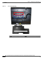
Higher Viewing Angle 3-11
Lower Viewing Angle 3-12
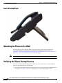
Mounting the Phone to the Wall
3-12
Verifying the Phone Startup Process
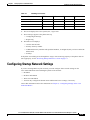
Configuring Startup Network Settings
CHAPTER
4
3-12
3-13
Configuring Settings on the Cisco Unified IP Phone
Configuration Menus on the Cisco Unified IP Phone
Displaying a Configuration Menu 4-2
Unlocking and Locking Options 4-3
Editing Values 4-3
Network Setup Menu
4-1
4-1
4-4
IPv4 Setup Menu Options
4-6
Cisco Unified IP Phone 6921, 6941, and 6961 Administration Guide for Cisco Unified Communications Manager 7.1 (SCCP)
vi
OL-19025-01
Contents
CHAPTER
5
Configuring Features, Templates, Services, and Users
5-1
Telephony Features Available for the Cisco Unified IP Phone
Join and Direct Transfer Policy 5-13
Configuring Corporate and Personal Directories
Configuring Corporate Directories 5-13
Configuring Personal Directory 5-14
5-1
5-13
Modifying Phone Button Templates 5-14
Modifying a Phone Button Template for Personal Address Book or Speed Dials
Configuring Softkey Templates
Setting Up Services
5-16
5-18
Adding Users to Cisco Unified Communications Manager
5-19
Managing the User Options Web Pages 5-19
Giving Users Access to the User Options Web Pages 5-19
Specifying Options that Appear on the User Options Web Pages
Configuring the Phone to Support Call Waiting
CHAPTER
6
5-15
Customizing the Cisco Unified IP Phone
5-21
5-22
6-1
Customizing and Modifying Configuration Files
6-1
Creating Custom Phone Rings 6-2
DistinctiveRingList File Format Requirements 6-2
PCM File Requirements for Custom Ring Types 6-3
Configuring a Custom Phone Ring 6-3
Configuring the Idle Display
6-3
Automatically Disabling the Cisco Unified IP Phone Backlight
CHAPTER
7
6-4
Viewing Model Information, Status, and Statistics on the Cisco Unified IP Phone
Model Information Screen
7-1
7-1
Status Menu 7-2
Status Messages Screen 7-2
Network Statistics Screen 7-6
Call Statistics Screen 7-8
CHAPTER
8
Monitoring the Cisco Unified IP Phone Remotely
Accessing the Web Page for a Phone
8-2
Disabling and Enabling Web Page Access
Device Information
Network Setup
8-1
8-3
8-3
8-4
Cisco Unified IP Phone 6921, 6941, and 6961 Administration Guide for Cisco Unified Communications Manager 7.1 (SCCP)
OL-19025-01
vii
Contents
Network Statistics
Device Logs
8-8
Streaming Statistics
CHAPTER
8-7
8-9
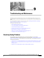
Troubleshooting and Maintenance
9
9-1
Resolving Startup Problems 9-1
Symptom: The Cisco Unified IP Phone Does Not Go Through its Normal Startup Process 9-2
Symptom: The Cisco Unified IP Phone Does Not Register with Cisco Unified Communications
Manager 9-2
Identifying Error Messages 9-3
Checking Network Connectivity 9-3
Verifying TFTP Server Settings 9-3
Verifying IP Addressing and Routing 9-3
Verifying DNS Settings 9-4
Cisco CallManager and TFTP Services Are Not Running 9-4
Creating a New Configuration File 9-4
Registering the Phone with Cisco Unified Communications Manager 9-5
Symptom: Cisco Unified IP Phone Unable to Obtain IP Address 9-5
Cisco Unified IP Phone Resets Unexpectedly 9-6
Verifying the Physical Connection 9-6
Identifying Intermittent Network Outages 9-6
Verifying DHCP Settings 9-6
Checking Static IP Address Settings 9-7
Verifying the Voice VLAN Configuration 9-7
Verifying that the Phones Have Not Been Intentionally Reset
Eliminating DNS or Other Connectivity Errors 9-7
Checking Power Connection 9-8
General Troubleshooting Tips
9-8
Resetting or Restoring the Cisco Unified IP Phone
Performing a Basic Reset 9-10
Performing a Factory Reset 9-11
Monitoring the Voice Quality of Calls
Troubleshooting Tips 9-12
Cleaning the Cisco Unified IP Phone
A
9-10
9-11
Where to Go for More Troubleshooting Information
APPENDIX
9-7
9-12
9-13
Providing Information to Users Via a Website
A-1
How Users Obtain Support for the Cisco Unified IP Phone
A-1
Cisco Unified IP Phone 6921, 6941, and 6961 Administration Guide for Cisco Unified Communications Manager 7.1 (SCCP)
viii
OL-19025-01
Contents
Giving Users Access to the User Options Web Pages
A-1
How Users Subscribe to Services and Configure Phone Features
How Users Access a Voice Messaging System
A-2
A-2
How Users Configure Personal Directory Entries A-3
Installing and Configuring the Cisco Unified IP Phone Address Book Synchronizer
APPENDIX
B
Supporting International Users
B-1
Installing the Cisco Unified Communications Manager Locale Installer
Support for International Call Logging
APPENDIX
C
Technical Specifications
C-1
D
C-1
C-2
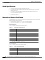
Network and Access Port Pinouts
APPENDIX
Basic Phone Administration Steps
C-2
D-1
Example User Information for these Procedures
D-1
Adding a User to Cisco Unified Communications Manager D-2
Adding a User From an External LDAP Directory D-3
Adding a User Directly to Cisco Unified Communications Manager
Configuring the Phone
E
E-1
E-2
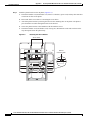
Installing the Bracket
F
D-8
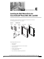
Installing the Wall Mount Kit for the Cisco Unified IP Phone 6921, 6941, and 6961
Before You Begin
APPENDIX
D-3
D-4
Performing Final End User Configuration Steps
APPENDIX
B-1
B-1
Physical and Operating Environment Specifications
Cable Specifications
A-3
E-2
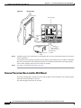
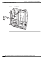
Cisco Unified IP Phone Non-Lockable Wall Mount
F-1
ADA Non-Lockable Wall Mount Kit for 6900 Series F-1
Components F-2
Before You Begin F-3
Install Non-Lockable Wall Mount Kit for Phone F-3
Remove Phone from Non-Lockable Wall Mount F-6
INDEX
Cisco Unified IP Phone 6921, 6941, and 6961 Administration Guide for Cisco Unified Communications Manager 7.1 (SCCP)
OL-19025-01
ix
Contents
Cisco Unified IP Phone 6921, 6941, and 6961 Administration Guide for Cisco Unified Communications Manager 7.1 (SCCP)
x
OL-19025-01
Preface
Overview
Cisco Unified IP Phone 6921, 6941, and 6961 Administration Guide for Cisco Unified Communications
Manager 7.1 (SCCP) provides the information you need to understand, install, configure, manage, and
troubleshoot the phones on a Voice-over-IP (VoIP) network.
Because of the complexity of an IP telephony network, this guide does not provide complete and detailed
information for procedures that you need to perform in Cisco Unified Communications Manager or other
network devices. See the “Obtaining Documentation, Obtaining Support, and Security Guidelines”
section on page xiii.
Audience
Network engineers, system administrators, or telecom engineers should review this guide to learn the
steps required to properly set up the Cisco Unified IP Phone on the network.
The tasks described are administration-level tasks and are not intended for end-users of the phones.
Many of the tasks involve configuring network settings and affect the phone’s ability to function in the
network.
Because of the close interaction between the Cisco Unified IP Phone and Cisco Unified
Communications Manager, many of the tasks in this manual require familiarity with Cisco Unified
Communications Manager.
Organization
This manual is organized as follows:
Chapter
Description
Chapter 1, “An Overview of the Cisco
Unified IP Phone”
Provides a conceptual overview and description of the Cisco
Unified IP Phone.
Chapter 2, “Preparing to Install the Cisco Unified IP Describes how the Cisco Unified IP Phone interacts with other key
Phone on Your Network”
IP telephony components, and provides an overview of the tasks
required prior to installation.
Cisco Unified IP Phone 6921, 6941, and 6961 Administration Guide for Cisco Unified Communications Manager 7.1 (SCCP)
OL-19025-01
xi
Preface
Chapter 3, “Setting Up the Cisco Unified IP Phone”
Describes how to properly and safely install and configure the Cisco
Unified IP Phone on your network.
Chapter 4, “Configuring Settings on the Cisco
Unified IP Phone”
Describes how to configure network settings, verify status, and make
global changes to the Cisco Unified IP Phone.
Chapter 5, “Configuring Features, Templates,
Services, and Users”
Provides an overview of procedures for configuring telephony
features, configuring directories, configuring phone button and
softkey templates, setting up services, and adding users to Cisco
Unified Communications Manager.
Chapter 6, “Customizing the Cisco
Unified IP Phone”
Explains how to customize phone ring sounds and the phone idle
display at your site.
Chapter 7, “Viewing Model Information, Status, and Explains how to view model information, status messages, network
Statistics on the Cisco Unified IP Phone”
statistics, and firmware information from the Cisco
Unified IP Phone.
Chapter 8, “Monitoring the Cisco Unified IP Phone
Remotely”
Describes the information that you can obtain from the phone’s web
page to remotely monitor the operation of a phone and to assist with
troubleshooting.
Chapter 9, “Troubleshooting and Maintenance”
Provides tips for troubleshooting the Cisco Unified IP Phone and the
Cisco Unified IP Phone Expansion Modules.
Appendix A, “Providing Information to Users Via a
Website”
Provides suggestions for setting up a website for providing users
with important information about their Cisco Unified IP Phones.
Appendix B, “Supporting International Users”
Provides information about setting up phones in non-English
environments.
Appendix C, “Technical Specifications”
Provides technical specifications of the Cisco Unified IP Phone.
Appendix D, “Basic Phone Administration Steps”
Provides procedures for basic administration tasks such as adding a
user and phone to Cisco Unified Communications Manager and then
associating the user to the phone.
Appendix E, “Installing the Wall Mount Kit for the
Cisco Unified IP Phone 6921, 6941, and 6961”
Contains instructions for installing the wall mount for the Cisco
Unified IP Phone.
Appendix F, “Cisco Unified IP Phone Non-Lockable Contains instructions for installing the Cisco Unified IP Phone
Wall Mount”
Non-Lockable Wall Mount.
Related Documentation
For more information about Cisco Unified IP Phones or Cisco Unified Communications Manager, refer
to the following publications:
Cisco Unified IP Phone 6900 Series
These publications are available at the following URL:
http://www.cisco.com/en/US/products/ps10326/tsd_products_support_series_home.html
•
Cisco Unified IP Phone 6921, 6941, and 6961 User Guide for Cisco Unified Communications
Manager 7.1 (SCCP)
•
Quick Start Guide for the Cisco Unified IP Phone 6921
•
Quick Start Guide for the Cisco Unified IP Phone 6941 for Administrative Assistants
•
Regulatory Compliance and Safety Information for Cisco Unified IP Phones
Cisco Unified IP Phone 6921, 6941, and 6961 Administration Guide for Cisco Unified Communications Manager 7.1 (SCCP)
xii
OL-19025-01
Preface
Cisco Unified Communications Manager Administration
Related publications are available at the following URL:
http://www.cisco.com/en/US/products/sw/voicesw/ps556/tsd_products_support_series_home.html
Cisco Unified Communications Manager Business Edition
Related publications are available at the following URL:
http://www.cisco.com/en/US/products/ps7273/tsd_products_support_series_home.html
Obtaining Documentation, Obtaining Support, and Security
Guidelines
For information on obtaining documentation, obtaining support, providing documentation feedback,
security guidelines, and also recommended aliases and general Cisco documents, see the monthly What’s
New in Cisco Product Documentation, which also lists all new and revised Cisco technical
documentation, at:
http://www.cisco.com/en/US/docs/general/whatsnew/whatsnew.html
Cisco Product Security Overview
This product contains cryptographic features and is subject to United States and local country laws
governing import, export, transfer and use. Delivery of Cisco cryptographic products does not imply
third-party authority to import, export, distribute or use encryption. Importers, exporters, distributors
and users are responsible for compliance with U.S. and local country laws. By using this product you
agree to comply with applicable laws and regulations. If you are unable to comply with U.S. and local
laws, return this product immediately.
Further information regarding U.S. export regulations may be found at
http://www.access.gpo.gov/bis/ear/ear_data.html.
Document Conventions
This document uses the following conventions:
Convention
Description
boldface font
Commands and keywords are in boldface.
italic font
Arguments for which you supply values are in italics.
[ ]
Elements in square brackets are optional.
{x|y|z}
Alternative keywords are grouped in braces and separated by vertical bars.
[x|y|z]
Optional alternative keywords are grouped in brackets and separated by
vertical bars.
string
A nonquoted set of characters. Do not use quotation marks around the string
or the string will include the quotation marks.
screen
font
Terminal sessions and information the system displays are in screen font.
Cisco Unified IP Phone 6921, 6941, and 6961 Administration Guide for Cisco Unified Communications Manager 7.1 (SCCP)
OL-19025-01
xiii
Preface
Convention
Description
boldface screen
font
Information you must enter is in boldface screen font.
italic screen font
Arguments for which you supply values are in italic screen font.
^
The symbol ^ represents the key labeled Control—for example, the key
combination ^D in a screen displaymeans hold down the Control key while
you press the D key.
< >
Nonprinting characters, such as passwords are in angle brackets.
Note
Caution
Means reader take note. Notes contain helpful suggestions or references to material not covered in the
publication.
Means reader be careful. In this situation, you might do something that could result in equipment
damage or loss of data.
Warnings use the following convention:
Warning
IMPORTANT SAFETY INSTRUCTIONS
This warning symbol means danger. You are in a situation that could cause
bodily injury. Before you work on any equipment, be aware of the hazards
involved with electrical circuitry and be familiar with standard practices for
preventing accidents. Use the statement number provided at the end of each
warning to locate its translation in the translated safety warnings that
accompanied this device. Statement 1071
SAVE THESE INSTRUCTIONS
Cisco Unified IP Phone 6921, 6941, and 6961 Administration Guide for Cisco Unified Communications Manager 7.1 (SCCP)
xiv
OL-19025-01
CH A P T E R
1
An Overview of the Cisco Unified IP Phone
The Cisco Unified IP Phone 6921, 6941, and 6961 provide voice communication over an Internet
Protocol (IP) network. The Cisco Unified IP Phone functions much like a digital business phone,
allowing you to place and receive phone calls and to access features such as mute, hold, transfer, speed
dial, call forward, and more. In addition, because the phone is connected to your data network, it offers
enhanced IP telephony features, including access to network information and services, and
customizeable features and services.
A Cisco Unified IP Phone, like other network devices, must be configured and managed. These phones
encode G.711a, G.711µ, G.729, G.729a, G.729ab, and decode G.711a, G.711µ, G.729, G.729a, and
G.729ab.
This chapter includes the following topics:
Caution
•
Understanding the Cisco Unified IP Phone 6921, 6941, and 6961, page 1-2
•
What Networking Protocols are Used?, page 1-9
•
What Features are Supported on the Cisco Unified IP Phone 6921, 6941, and 6961?, page 1-11
•
Overview of Configuring and Installing Cisco Unified IP Phones, page 1-13
•
Terminology Differences, page 1-20
Using a cell, mobile, or GSM phone, or two-way radio in close proximity to a Cisco Unified IP Phone
might cause interference. For more information, refer to the manufacturer’s documentation of the
interfering device.
Cisco Unified IP Phone 6921, 6941, and 6961 Administration Guide for Cisco Unified Communications Manager 7.1 (SCCP)
OL-19025-01
1-1
Chapter 1
An Overview of the Cisco Unified IP Phone
Understanding the Cisco Unified IP Phone 6921, 6941, and 6961
Understanding the Cisco Unified IP Phone 6921, 6941, and 6961
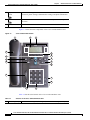
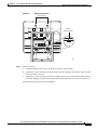
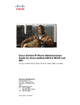
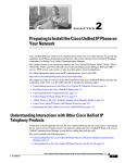
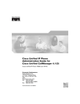
Figure 1-1 shows the main components of the Cisco Unified IP Phone 6921.
Figure 1-1
Cisco Unified IP Phone 6921
1
2
17
3
16
4
15
5
14
6
7
1
/.@
2
ABC
DEF
3
1
6
2
8
4
13
GHI
7
PQRS
5
JKL
8
TUV
MNO
9
9
WXYZ
0
192525
10
12
11
Table 1-1 describes the buttons on the Cisco Unified IP Phone 6921.
Table 1-1
Features on the Cisco Unified IP Phone 6921
1
Handset light strip Indicates an incoming call (flashing red) or new voice message (steady red).
2
Phone screen
Shows information about your phone such as directory number, active call
and line status, softkey options, speed dials, placed calls, and phone menu
listings.
3
Softkey buttons
Enables softkey options displayed on the phone screen.
Cisco Unified IP Phone 6921, 6941, and 6961 Administration Guide for Cisco Unified Communications Manager 7.1 (SCCP)
1-2
OL-19025-01
Chapter 1
An Overview of the Cisco Unified IP Phone
Understanding the Cisco Unified IP Phone 6921, 6941, and 6961
4
Transfer button
Transfers a call.
5
Conference button Creates a conference call.
6
Hold button
7
Navigation bar and The Navigation bar allows you to scroll through menus and highlight items.
Select button
When phone is on-hook, displays phone numbers from your Placed Call
listings (up arrow) or your speed dials (down arrow).
Places an active call on hold.
The Select button (in the middle of the Navigation bar) allows you to select
a highlighted item.
8
Line 1 and Line 2
buttons
1
Line 1 selects the primary phone line. Phone lines and intercom lines (line
buttons).
Depending on the settings, Line 2 may provide access to:
2
•
Secondary phone line
•
Speed-dial numbers (speed-dial buttons)
•
Web-based services (for example, a Personal Address Book button)
Buttons illuminate to indicate status:
9
Headset button
•
Green, steady—Active call
•
Green, flashing—Held call
•
Amber, flashing—Incoming call or reverting call
•
Red, steady—Remote line in use (shared line)
•
Red, flashing—Remote line on hold
Toggles the headset on or off. When the headset is on, the button is lit.
10 Speakerphone
button
Toggles the speakerphone on or off. When the speakerphone is on, the button
is lit.
11 Keypad
Allows you to dial phone numbers, enter letters, and choose menu items.
12 Mute button
Toggles the microphone on or off. When the microphone is muted, the button
is lit.
13 Volume button
Controls the handset, headset, and speakerphone volume (off-hook) and the
ringer volume (on-hook).
14 Messages button
Auto-dials your voicemail (varies by system).
Cisco Unified IP Phone 6921, 6941, and 6961 Administration Guide for Cisco Unified Communications Manager 7.1 (SCCP)
OL-19025-01
1-3
Chapter 1
An Overview of the Cisco Unified IP Phone
Understanding the Cisco Unified IP Phone 6921, 6941, and 6961
15 Applications
button
Opens/closes the Applications menu. Use it to access call history, user
preferences, phone settings, administration settings, and phone information.
16 Contacts button
Opens/closes the Directories menu. Use it to access personal and corporate
directories.
17 Handset
Phone handset.
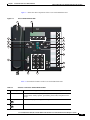
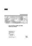
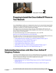
Figure 1-2 shows the main components of the Cisco Unified IP Phone 6941.
Figure 1-2
Cisco Unified IP Phone 6941
1
2
3
17
4
16
5
15
6
14
7
8
13
9
192526
10
12
11
Table 1-2 describes the buttons on the Cisco Unified IP Phone 6941.
Table 1-2
1
Features on the Cisco Unified IP Phone 6941
Handset light strip Indicates an incoming call (flashing red) or new voice message (steady red).
Cisco Unified IP Phone 6921, 6941, and 6961 Administration Guide for Cisco Unified Communications Manager 7.1 (SCCP)
1-4
OL-19025-01
Chapter 1
An Overview of the Cisco Unified IP Phone
Understanding the Cisco Unified IP Phone 6921, 6941, and 6961
2
Phone screen
Shows information about your phone such as directory number, active call
and line status, softkey options, speed dials, placed calls, and phone menu
listings.
3
Programmable
feature buttons
Depending on the configuration, programmable feature buttons provide
access to:
•
Phone lines and intercom lines
•
Speed-dial numbers (speed-dial buttons, including the line status
speed-dial features)
•
Web-based services (for example, a Personal Address Book button)
•
Call features (for example, a Privacy button)
Buttons illuminate to indicate status:
•
Green, steady—Active call or two-way intercom call
•
Green, flashing—Held call
•
Amber, steady—Privacy in use, one-way intercom call, DND active, or
logged into Hunt Group
•
Amber, flashing—Incoming call or reverting call
•
Red, steady—Remote line in use (shared line or line status)
•
Red, flashing—Remote line on hold
4
Softkey buttons
Enables softkey options displayed on the phone screen.
5
Transfer button
Transfers a call.
6
Conference button Creates a conference call.
7
Hold button
Places an active call on hold.
8
Navigation bar and
Select button
The Navigation bar allows you to scroll through menus and highlight items.
When phone is on-hook, displays phone numbers from your Placed Call
listings (up arrow) or your speed dials (down arrow).
The Select button (in the middle of the Navigation bar) allows you to select
a highlighted item.
9
Headset button
Toggles the headset on or off. When the headset is on, the button is lit.
10 Speakerphone
button
Toggles the speakerphone on or off. When the speakerphone is on, the button
is lit.
11 Keypad
Allows you to dial phone numbers, enter letters, and choose menu items (by
entering the item number).
Cisco Unified IP Phone 6921, 6941, and 6961 Administration Guide for Cisco Unified Communications Manager 7.1 (SCCP)
OL-19025-01
1-5
Chapter 1
An Overview of the Cisco Unified IP Phone
Understanding the Cisco Unified IP Phone 6921, 6941, and 6961
12 Mute button
Toggles the microphone on or off. When the microphone is muted, the button
is lit.
13 Volume button
Controls the handset, headset, and speakerphone volume (off-hook) and the
ringer volume (on-hook).
14 Messages button
Auto-dials your voice message service (varies by service).
15 Applications
button
Opens/closes the Applications menu. Use it to access call history, user
preferences, phone settings, administration settings, and phone information.
16 Contacts button
Opens/closes the Directories menu. Use it to access personal and corporate
directories.
17 Handset
Phone handset.
Cisco Unified IP Phone 6921, 6941, and 6961 Administration Guide for Cisco Unified Communications Manager 7.1 (SCCP)
1-6
OL-19025-01
Chapter 1
An Overview of the Cisco Unified IP Phone
Understanding the Cisco Unified IP Phone 6921, 6941, and 6961
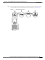
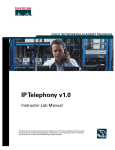
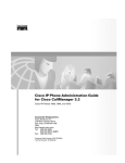
Figure 1-3 shows the main components of the Cisco Unified IP Phone 6961.
Figure 1-3
Cisco Unified IP Phone 6961
1
2
17
3
16
4
15
5
14
6
7
1
/.@
4
13
GHI
7
PQRS
2
ABC
5
JKL
8
TUV
8
3
DEF
6
MNO
9
9
WXYZ
0
192527
10
12
11
Table 1-3 describes the buttons on the Cisco Unified IP Phone 6961.
Table 1-3
Features on the Cisco Unified IP Phone 6961
1
Handset light strip Indicates an incoming call (flashing red) or new voice message (steady red).
2
Phone screen
Shows information about your phone such as directory number, active call
and line status, softkey options, speed dials, placed calls, and phone menu
listings.
3
Softkey buttons
Enables softkey options displayed on the phone screen.
4
Transfer button
Transfers a call.
Cisco Unified IP Phone 6921, 6941, and 6961 Administration Guide for Cisco Unified Communications Manager 7.1 (SCCP)
OL-19025-01
1-7
Chapter 1
An Overview of the Cisco Unified IP Phone
Understanding the Cisco Unified IP Phone 6921, 6941, and 6961
5
Conference button Creates a conference call.
6
Hold button
7
Navigation bar and The Navigation bar allows you to scroll through menus and highlight items.
select button
When phone is on-hook, displays phone numbers from your Placed Call
listings (up arrow) or your speed dials (down arrow).
Places an active call on hold.
The Select button allows you to select a highlighted item.
8
Programmable
feature buttons
Depending on the configuration, programmable feature buttons provide
access to:
•
Phone lines and intercom lines
•
Speed-dial numbers (speed-dial buttons, including the line status
speed-dial features)
•
Web-based services (For example, a Personal Address Book button)
•
Call features (For example, a Privacy button)
Buttons illuminate to indicate status:
9
Headset button
•
Green, steady—Active call or two-way intercom call
•
Green, flashing—Held call
•
Amber, steady—Privacy in use, one-way intercom call, DND active, or
logged into Hunt Group
•
Amber, flashing—Incoming call or reverting call
•
Red, steady—Remote line in use (shared line or line status)
•
Red, flashing—Remote line on hold
Toggles the headset on or off. When the headset is on, the button is lit.
10 Speakerphone
button
Toggles the speakerphone on or off. When the speakerphone is on, the button
is lit.
11 Keypad
Allows you to dial phone numbers, enter letters, and choose menu items (by
entering the item number).
12 Mute button
Toggles the microphone on or off. When the microphone is muted, the button
is lit.
13 Volume button
Controls the handset, headset, and speakerphone volume (off-hook) and the
ringer volume (on-hook).
14 Messages button
Auto-dials your voice messaging system (varies by system).
Cisco Unified IP Phone 6921, 6941, and 6961 Administration Guide for Cisco Unified Communications Manager 7.1 (SCCP)
1-8
OL-19025-01
Chapter 1
An Overview of the Cisco Unified IP Phone
What Networking Protocols are Used?
15 Applications
button
Opens/closes the Applications menu. Use it to access call history, user
preferences, phone settings, administration settings, and phone information.
16 Contacts button
Opens/closes the Directories menu. Use it to access personal and corporate
directories.
17 HandSet
Phone handset.
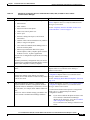
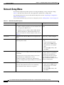
What Networking Protocols are Used?
Cisco Unified IP Phones support several industry-standard and Cisco networking protocols required for
voice communication. Table 1-4 provides an overview of the networking protocols that the
Cisco Unified IP Phone 6921, 6941, and 6961 support.
Table 1-4
Supported Networking Protocols on the Cisco Unified IP Phone
Networking Protocol
Purpose
Usage Notes
Bootstrap Protocol
(BootP)
BootP enables a network device such as
the Cisco Unified IP Phone to discover
certain startup information, such as its IP
address.
—
Cisco Discovery Protocol
(CDP)
CDP is a device-discovery protocol that
runs on all Cisco-manufactured
equipment.
The Cisco Unified IP Phone uses CDP to
communicate information such as auxiliary VLANID,
per port power management details, and Quality of
Service (QoS) configuration information with the
Cisco Catalyst switch.
Using CDP, a device can advertise its
existence to other devices and receive
information about other devices in the
network.
Dynamic Host
Configuration Protocol
(DHCP)
DHCP dynamically allocates and assigns
an IP address to network devices.
DHCP is enabled by default. If disabled, you must
manually configure the IP address, subnet mask,
gateway,
and a TFTP server on each phone locally.
DHCP enables you to connect an IP phone
into the network and have the phone
Cisco recommends that you use DHCP custom
become operational without your needing option 150. With this method, you configure the
TFTP server IP address as the option value. For
to manually assign an IP address or to
configure additional network parameters. additional supported DHCP configurations, go to
the Dynamic Host Configuration Protocol chapter
and the Cisco TFTP chapter in the Cisco Unified
Communications Manager System Guide.
Note
Hypertext Transfer
Protocol (HTTP)
If you cannot use option 150, you may try
using DHCP option 66.
HTTP is the standard way of transferring Cisco Unified IP Phones use HTTP for the XML
information and moving documents across services and for troubleshooting purposes.
the Internet and the web.
Cisco Unified IP Phone 6921, 6941, and 6961 Administration Guide for Cisco Unified Communications Manager 7.1 (SCCP)
OL-19025-01
1-9
Chapter 1
An Overview of the Cisco Unified IP Phone
What Networking Protocols are Used?
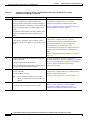
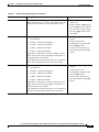
Table 1-4
Supported Networking Protocols on the Cisco Unified IP Phone (continued)
Networking Protocol
Purpose
Usage Notes
Internet Protocol (IP)
IP is a messaging protocol that addresses
and sends packets across the network.
To communicate using IP, network devices must
have an assigned IP address, subnet, and gateway.
IP addresses, subnets, and gateways identifications
are automatically assigned if you are using the
Cisco Unified IP Phone with Dynamic Host
Configuration Protocol (DHCP). If you are not
using DHCP, you must manually assign these
properties to each phone locally.
Real-Time Transport
Protocol (RTP)
RTP is a standard protocol for transporting Cisco Unified IP Phones use the RTP protocol to
real-time data, such as interactive voice
send and receive real-time voice traffic from other
and video, over data networks.
phones and gateways.
Real-Time Control
Protocol (RTCP)
RTCP works in conjunction with RTP to
provide QoS data (such as jitter, latency,
and round trip delay) on RTP streams.
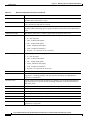
Skinny Client Control
Protocol (SCCP)
SCCP includes a messaging set that allows Cisco Unified IP Phone 6921, 6941, and 6961 use
communications between call control
SCCP, version 15 for call control.
servers and endpoint clients such as IP
Phones. SCCP is proprietary to Cisco
Systems.
Transmission Control
Protocol (TCP)
TCP is a connection-oriented transport
protocol.
Trivial File Transfer
Protocol (TFTP)
TFTP allows you to transfer files over the TFTP requires a TFTP server in your network,
which can be automatically identified from the
network.
DHCP server. If you want a phone to use a TFTP
On the Cisco Unified IP Phone, TFTP
enables you to obtain a configuration file server other than the one specified by the DHCP
server, you must manually assign the IP address of
specific to the phone type.
the TFTP server by using the Network
Configuration menu on the phone.
RTCP is disabled by default, but you can enable it
on a per phone basis by using Cisco Unified
Communications Manager.
Cisco Unified IP Phones use TCP to connect to
Cisco Unified Communications Manager and to
access XML services.
For more information, go to the Cisco TFTP chapter
in the Cisco Unified Communications Manager
System Guide.
User Datagram Protocol
(UDP)
UDP is a connectionless messaging
protocol for delivery of data packets.
Cisco Unified IP Phones transmit and receive RTP
streams, which utilize UDP.
Related Topics
•
Understanding Interactions with Other Cisco Unified IP Telephony Products, page 2-1
•
Understanding the Phone Startup Process, page 2-6
•
Network Setup Menu, page 4-4
Cisco Unified IP Phone 6921, 6941, and 6961 Administration Guide for Cisco Unified Communications Manager 7.1 (SCCP)
1-10
OL-19025-01
Chapter 1
An Overview of the Cisco Unified IP Phone
What Features are Supported on the Cisco Unified IP Phone 6921, 6941, and 6961?
What Features are Supported on the Cisco Unified
IP Phone 6921, 6941, and 6961?
Cisco Unified IP Phones function much like a digital business phone, allowing you to place and receive
phone calls. In addition to traditional telephony features, the Cisco Unified IP Phone includes features
that enable you to administer and monitor the phone as a network device.
This section includes the following topics:
•
Feature Overview, page 1-11
•
Configuring Telephony Features, page 1-12
•
Configuring Network Parameters Using the Cisco Unified IP Phone, page 1-12
•
Providing Users with Feature Information, page 1-12
Feature Overview
Cisco Unified IP Phones provide traditional telephony functionality, such as call forwarding and
transferring, redialing, speed dialing, conference calling, and voice messaging system access.
Cisco Unified IP phones also provide a variety of other features. For an overview of the telephony
features that the Cisco Unified IP Phone supports and for tips on configuring them, see the “Telephony
Features Available for the Cisco Unified IP Phone” section on page 5-1.
As with other network devices, you must configure Cisco Unified IP Phones to prepare them to access
Cisco Unified Communications Manager and the rest of the IP network. By using DHCP, you have fewer
settings to configure on a phone, but if your network requires it, you can manually configure an IP
address, TFTP server, subnet information, and so on. For instructions on configuring the network
settings on the Cisco Unified IP Phones, see Chapter 4, “Configuring Settings on the Cisco Unified IP
Phone.”
Cisco Unified IP Phones can interact with other services and devices on your IP network to provide
enhanced functionality. For example, you can integrate Cisco Unified Communications Manager with
the corporate Lightweight Directory Access Protocol 3 (LDAP3) standard directory to enable users to
search for co-worker contact information directly from their IP phones. You can also use XML to enable
users to access information such as weather, stocks, quote of the day, and other web-based information.
For information about configuring such services, see the “Join and Direct Transfer Policy” section on
page 5-13 and the “Setting Up Services” section on page 5-18.
Finally, because the Cisco Unified IP Phone is a network device, you can obtain detailed status
information from it directly. This information can assist you with troubleshooting any problems users
might encounter when using their IP phones. See Chapter 7, “Viewing Model Information, Status, and
Statistics on the Cisco Unified IP Phone,” for more information.
Related Topics
•
Configuring Settings on the Cisco Unified IP Phone, page 4-1
•
Configuring Features, Templates, Services, and Users, page 5-1
•
Troubleshooting and Maintenance, page 9-1
Cisco Unified IP Phone 6921, 6941, and 6961 Administration Guide for Cisco Unified Communications Manager 7.1 (SCCP)
OL-19025-01
1-11
Chapter 1
An Overview of the Cisco Unified IP Phone
What Features are Supported on the Cisco Unified IP Phone 6921, 6941, and 6961?
Configuring Telephony Features
You can modify additional settings for the Cisco Unified IP Phone from Cisco Unified Communications
Manager Administration. Use Cisco Unified Communications Manager Administration to set up phone
registration criteria and calling search spaces, to configure corporate directories and services, and to
modify phone button templates, among other tasks. See the “Telephony Features Available for the Cisco
Unified IP Phone” section on page 5-1 and the Cisco Unified Communications Manager documentation
for additional information.
For more information about Cisco Unified Communications Manager Administration, refer to
Cisco Unified Communications Manager documentation, including Cisco Unified Communications
Manager Administration Guide. You can also use the context-sensitive help available within the
application for guidance.
You can access Cisco Unified Communications Manager documentation at this location:
http://www.cisco.com/en/US/products/sw/voicesw/ps556/tsd_products_support_series_home.html
You can access Cisco Unified Communications Manager Business Edition documentation at this
location:
http://www.cisco.com/en/US/products/ps7273/tsd_products_support_series_home.html
Related Topic
•
Telephony Features Available for the Cisco Unified IP Phone, page 5-1
Configuring Network Parameters Using the Cisco Unified IP Phone
You can configure parameters such as DHCP, TFTP, and IP settings on the phone itself. You can also
obtain statistics about a current call or firmware versions on the phone.
For more information about configuring features and viewing statistics from the phone, see Chapter 4,
“Configuring Settings on the Cisco Unified IP Phone” and see Chapter 7, “Viewing Model Information,
Status, and Statistics on the Cisco Unified IP Phone.”
Providing Users with Feature Information
If you are a system administrator, you are likely the primary source of information for Cisco Unified IP
Phone users in your network or company. To ensure that you distribute the most current feature and
procedural information, familiarize yourself with Cisco Unified IP Phone documentation on the
Cisco Unified IP Phone web site:
http://www.cisco.com/en/US/products/ps10326/tsd_products_support_series_home.html
From this site, you can view various user documentation.
In addition to providing documentation, it is important to inform users of available Cisco Unified IP
Phone features—including those specific to your company or network—and of how to access and
customize those features, if appropriate.
For a summary of some of the key information that phone users need their system administrators to
provide, see Appendix A, “Providing Information to Users Via a Website.”
Cisco Unified IP Phone 6921, 6941, and 6961 Administration Guide for Cisco Unified Communications Manager 7.1 (SCCP)
1-12
OL-19025-01
Chapter 1
An Overview of the Cisco Unified IP Phone
Understanding Security Features for Cisco Unified IP Phones
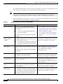
Understanding Security Features for Cisco Unified IP Phones
Cisco Unified IP Phone 6921, 6941, and 6961 support basic security features. Table 1-5 provides an
overview of the security features that the Cisco Unified IP Phone 6921, 6941, and 6961 support.
Table 1-5
Overview of Security Features
Feature
Description
Optional disabling of the web server
functionality for a phone
You can prevent access to a phone’s web page, which displays a variety of
operational statistics for the phone. See the “Disabling and Enabling Web Page
Access” section on page 8-3.
Phone hardening
Additional security options, which you control from Cisco Unified
Communications Manager Administration:
•
Disabling PC port
•
Disabling PC Voice VLAN access
•
Disabling access to web pages for a phone
All Cisco Unified IP Phones that support Cisco Unified Communications Manager use a security profile,
which defines whether the phone is nonsecure, authenticated, or encrypted. Cisco Unified IP Phone
6921, 6941, and 6961 only supports a nonsecure profile.
For information about configuring the security profile and applying the profile to the phone, refer to
Cisco Unified Communications Manager Security Guide.
Overview of Configuring and Installing Cisco Unified IP Phones
When deploying a new IP telephony system, system administrators and network administrators must
complete several initial configuration tasks to prepare the network for IP telephony service. For
information and a checklist for setting up and configuring a Cisco IP telephony network, go to the
System Configuration Overview chapter in Cisco Unified Communications Manager System Guide.
After you have set up the IP telephony system and configured system-wide features in Cisco Unified
Communications Manager, you can add IP phones to the system.
The following topics provide an overview of procedures for adding Cisco Unified IP Phones to your
network:
•
Configuring Cisco Unified IP Phones in Cisco Unified Communications Manager, page 1-13
•
Installing Cisco Unified IP Phones, page 1-18
Configuring Cisco Unified IP Phones in Cisco Unified Communications
Manager
To add phones to the Cisco Unified Communications Manager database, you can use:
•
Auto-registration
•
Cisco Unified Communications Manager Administration
•
Bulk Administration Tool (BAT)
Cisco Unified IP Phone 6921, 6941, and 6961 Administration Guide for Cisco Unified Communications Manager 7.1 (SCCP)
OL-19025-01
1-13
Chapter 1
An Overview of the Cisco Unified IP Phone
Overview of Configuring and Installing Cisco Unified IP Phones
•
BAT and the Tool for Auto-Registered Phones Support (TAPS)
For more information about these choices, see the “Adding Phones to the Cisco Unified
Communications Manager Database” section on page 2-7.
For general information about configuring phones in Cisco Unified Communications Manager, refer to
the following documentation:
• Cisco Unified IP Phones, Cisco Unified Communications Manager System Guide
•
Cisco Unified IP Phone Configuration, Cisco Unified Communications Manager Administration
Guide
•
Autoregistration Configuration, Cisco Unified Communications Manager Administration Guide
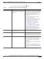
Checklist for Configuring the Cisco Unified IP Phone 6921, 6941, and 6961 in Cisco Unified
Communications Manager
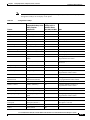
Table 1-6 provides an overview and checklist of configuration tasks for the Cisco Unified
IP Phone 6921, 6941, and 6961 in Cisco Unified Communications Manager Administration. The list
presents a suggested order to guide you through the phone configuration process. Some tasks are
optional, depending on your system and user needs. For detailed procedures and information, refer to
the sources in the list.
Cisco Unified IP Phone 6921, 6941, and 6961 Administration Guide for Cisco Unified Communications Manager 7.1 (SCCP)
1-14
OL-19025-01
Chapter 1
An Overview of the Cisco Unified IP Phone
Overview of Configuring and Installing Cisco Unified IP Phones
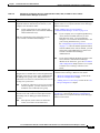
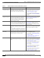
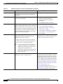
Table 1-6
Task
1.
Checklist for Configuring the Cisco Unified IP Phone 6921, 6941, and 6961 in Cisco Unified
Communications Manager
Purpose
For More Information
Gather the following information about the phone:
For more information, go to the “Cisco Unified IP
Phones chapter in the Cisco Unified Communications
Manager System Guide.
•
Phone Model
•
MAC address
•
Physical location of the phone
•
Name or user ID of phone user
•
Device pool
•
Partition, calling search space, and location
information
•
Number of lines and associated directory numbers
(DNs) to assign to the phone
•
Cisco Unified Communications Manager user to
associate with the phone
•
Phone usage information that affects phone
button template, softkey template, phone features,
IP Phone services, or phone applications
See the “Telephony Features Available for the Cisco
Unified IP Phone” section on page 5-1.
Provides list of configuration requirements for setting
up phones.
Identifies preliminary configuration that you need to
perform before configuring individual phones, such as
phone button templates or softkey templates.
2.
Verify that you have sufficient unit licenses for your
phone.
For more information, go to the License Unit Report
chapter in the Cisco Communications Manager
Administration Guide.
3.
Customize phone button templates (if required).
For more information, go to the Phone Button Template
Configuration chapter in the Cisco Communications
Manager Administration Guide.
Changes the number of line buttons, speed-dial
buttons, Service URL buttons or adds a Privacy button
See the “Modifying Phone Button Templates” section on
to meet user needs.
page 5-14.
4.
Add and configure the phone by completing the
required fields in the Phone Configuration window.
Required fields are indicated by an asterisk (*) next to
the field name; for example, MAC address and device
pool.
The device with its default settings gets added to the
Cisco Unified Communications Manager database.
For more information, go to the Cisco Unified IP Phone
Configuration chapter in the Cisco Communications
Manager Administration Guide.
For information about Product Specific Configuration
fields, refer to “?” Button Help in the Phone
Configuration window.
Note
If you want to add both the phone and user to the
Cisco Unified Communications Manager
database at the same time, go to the User/Phone
Add Configuration chapter in the
Cisco Communications Manager Administration
Guide.
Cisco Unified IP Phone 6921, 6941, and 6961 Administration Guide for Cisco Unified Communications Manager 7.1 (SCCP)
OL-19025-01
1-15
Chapter 1
An Overview of the Cisco Unified IP Phone
Overview of Configuring and Installing Cisco Unified IP Phones
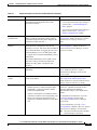
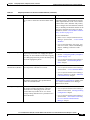
Table 1-6
Task
5.
Checklist for Configuring the Cisco Unified IP Phone 6921, 6941, and 6961 in Cisco Unified
Communications Manager (continued)
Purpose
For More Information
Add and configure directory numbers (lines) on the
phone by completing the required fields in the
Directory Number Configuration window. Required
fields are indicated by an asterisk (*) next to the field
name; for example, directory number and presence
group.
For more information, go to the “Directory Number
Configuration” chapter in the Cisco Unified
Communications Manager Administration Guide.
See the “Telephony Features Available for the Cisco
Unified IP Phone” section on page 5-1.
Adds primary and secondary directory numbers and
features associated with directory numbers to the
phone.
6.
Customize softkey templates.
For more information, go to the “Softkey Template
Configuration” chapter in the Cisco Unified
Adds, deletes, or changes order of softkey features
Communications Manager Administration Guide.
that display on the user’s phone to meet feature usage
needs.
For more information, go to the “Configuring
Speed-Dial Buttons” section in the “Cisco
Unified IP Phone Configuration” chapter in the Cisco
Unified Communications Manager Administration
Guide.
See the “Configuring Softkey Templates” section on
page 5-16.
7.
Configure speed-dial buttons and assign speed-dial
numbers (optional).
Adds speed-dial buttons and numbers.
Users can change speed-dial settings on their phones
by using Cisco Unified CM User Options.
8.
For more information, go to the “Configuring
Speed-Dial Buttons or Abbreviated Dialing” section in
the”Cisco Unified IP Phone Configuration” chapter in
the Cisco Unified Communications Manager
Administration Guide.
Configure Cisco Unified IP Phone services and assign For more information, go to the “IP Phone Services
services (optional).
Configuration” chapter in the Cisco Communications
Manager Administration Guide
Provides IP Phone services.
See the “Setting Up Services” section on page 5-18.
Note
Users can add or change services on their
phones by using the Cisco Unified CM User
Options.
9.
Assign services to programmable buttons (optional).
Provides access to an IP phone service or URL.
For more information, go to the “Adding a Service URL
Button” section in the Cisco Unified IP Phone
Configuration chapter in the Cisco Unified
Communications Manager Administration Guide.
Cisco Unified IP Phone 6921, 6941, and 6961 Administration Guide for Cisco Unified Communications Manager 7.1 (SCCP)
1-16
OL-19025-01
Chapter 1
An Overview of the Cisco Unified IP Phone
Overview of Configuring and Installing Cisco Unified IP Phones
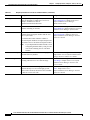
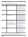
Table 1-6
Checklist for Configuring the Cisco Unified IP Phone 6921, 6941, and 6961 in Cisco Unified
Communications Manager (continued)
Task
Purpose
For More Information
10.
Add user information by configuring required fields.
Required fields are indicated by an asterisk (*); for
example, User ID and last name.
For more information, go to the End User Configuration
chapter in the Cisco Unified Communications Manager
Administration Guide.
Note
Assign a password (for User Options web
See the “Adding Users to Cisco Unified
pages) and PIN (for Cisco Extension Mobility Communications Manager” section on page 5-19.
and Personal Directory).
Note
If your company uses a a Lightweight Directory
Access Protocol (LDAP) directory to store
information on users, you can install and
configure Cisco Unified Communications to use
your existing LDAP directory, refer to
the“Configuring Corporate Directories” section
on page 5-13. Once the Enable Synchronization
from the LDAP Server field is enabled, you will
not be able to add additional users from Cisco
Unified Communications Manager
Administration.
Adds user information to the global directory for
Cisco Unified Communications Manager.
Note
11.
Refer to the following sections in the Cisco Unified
Assigns users a common list of roles and permissions Communications Manager Administration Guide:
that apply to all users in a user group. Administrators • “End User Configuration Settings” section in the
“End User Configuration” chapter.
can manage user groups, roles, and permissions to
control the level of access (and, therefore, the level of
• “Adding Users to a User Group” section in the “User
security) for system users.
Group Configuration” chapter.
Associate a user to a user group.
Note
12.
If you want to add both the phone and user to the
Cisco Unified Communications Manager
database at the same time, go to the User/Phone
Add Configurations chapter in the Cisco Unified
Communications Manager Administration
Guide.
In order for end users to access Cisco Unified
CM User Options, you must add users to the
standard Cisco CCM End Users group.
Associate a user with a phone (optional).
Provides users with control over their phone such a
forwarding calls or adding speed-dial numbers or
services.
Note
For more information, go to the “Associating Devices to
an End User” section in the End User Configuration
chapter in the Cisco Unified Communications Manager
Administration Guide.
Some phones, such as those in conference
rooms, do not have an associated user.
Cisco Unified IP Phone 6921, 6941, and 6961 Administration Guide for Cisco Unified Communications Manager 7.1 (SCCP)
OL-19025-01
1-17
Chapter 1
An Overview of the Cisco Unified IP Phone
Overview of Configuring and Installing Cisco Unified IP Phones
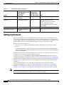
Installing Cisco Unified IP Phones
After you have added the phones to the Cisco Unified Communications Manager database, you can
complete the phone installation. You (or the phone users) can install the phone at the users’s location.
The Cisco Unified IP Phone Installation Guide, which is provided on the cisco.com web site, provides
directions for connecting the phone handset, cables, and other accessories.
Note
Before you install a phone, even if it is new, upgrade the phone to the current firmware image. For
information about upgrading, refer to the Readme file for your phone, which is located at:
http://www.cisco.com/kobayashi/sw-center/index.shtml
After the phone is connected to the network, the phone startup process begins, and the phone registers
with Cisco Unified Communications Manager. To finish installing the phone, configure the network
settings on the phone depending on whether you enable or disable DHCP service.
If you used auto-registration, you need to update the specific configuration information for the phone
such as associating the phone with a user, changing the button table, or directory number.
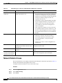
Checklist for Installing the Cisco Unified IP Phone 6921, 6941, and 6961
Table 1-7 provides an overview and checklist of installation tasks for the Cisco Unified IP Phone 6921,
6941, and 6961. The list presents a suggested order to guide you through the phone installation. Some
tasks are optional, depending on your system and user needs. For detailed procedures and information,
refer to the sources in the list.
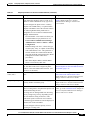
Table 1-7
Task
1.
Installation Checklist for the Cisco Unified IP Phone 6921, 6941, and 6961
Purpose
For More Information
Choose the power source for the phone:
See the “Providing Power to the Cisco Unified IP Phone”
section on page 2-3.
•
Power over Ethernet (PoE)
•
External power supply
Determines how the phone receives power.
2.
3.
Assemble the phone, adjust phone placement, and
connect the network cable.
See the “Installing the Cisco Unified IP Phone” section
on page 3-5.
Locates and installs the phone in the network.
See the “Footstand” section on page 3-8.
Monitor the phone startup process.
See the “Verifying the Phone Startup Process” section on
page 3-12.
Adds primary and secondary directory numbers and
features associated with directory numbers to the
phone.
Verifies that phone is configured properly.
Cisco Unified IP Phone 6921, 6941, and 6961 Administration Guide for Cisco Unified Communications Manager 7.1 (SCCP)
1-18
OL-19025-01
Chapter 1
An Overview of the Cisco Unified IP Phone
Overview of Configuring and Installing Cisco Unified IP Phones
Table 1-7
Task
4.
Installation Checklist for the Cisco Unified IP Phone 6921, 6941, and 6961 (continued)
Purpose
For More Information
If you are configuring the network settings on the
phone, you can set up an IP address for the phone by
either using DHCP or manually entering an IP
address.
See the “Configuring Startup Network Settings” section
on page 3-13.
See the “Network Setup Menu” section on page 4-4.
Using DHCP—To enable DHCP and allow the DHCP
server to automatically assign an IP address to the
Cisco Unified IP Phone and direct the phone to a
TFTP server, choose Applications > Admin Settings
> Network Setup > IPv4 Setup and:
•
To enable DHCP, set DHCP Enabled to Yes.
DHCP is enabled by default.
•
To use an alternate TFTP server, set Alternate
TFTP Server to Yes, and enter the IP address for
the TFTP Server.
Note
Consult with the network administrator to
determine whether you need to assign an
alternative TFTP server instead of using the
TFTP server assigned by DHCP.
Without DHCP—You must configure the IP address,
subnet mask, TFTP server, and default router locally
on the phone, choose Applications > Admin Settings
> Network Setup > IPv4 Setup:
To disable DHCP and manually set an IP address:
a.
To disable DHCP, set DHCP Enabled to No.
b.
Enter the static IP address for phone.
c.
Enter the subnet mask.
d.
Enter the default router IP addresses.
e.
Set Alternate TFTP Server to Yes, and enter the IP
address for TFTP Server 1.
You must also enter the domain name where the phone
resides by Choosing Applications > Admin Settings
> Network Configuration.
5.
Make calls with the Cisco Unified IP Phone.
Verifies that the phone and features work correctly.
6.
Refer to Cisco Unified IP Phone 6921, 6941, and 6961
User Guide for Cisco Unified Communications Manager
7.1
Provide information to end users about how to use
See Appendix A, “Providing Information to Users Via a
their phones and how to configure their phone options. Website.”
Ensures that users have adequate information to
successfully use their Cisco Unified IP Phones.
Cisco Unified IP Phone 6921, 6941, and 6961 Administration Guide for Cisco Unified Communications Manager 7.1 (SCCP)
OL-19025-01
1-19
Chapter 1
An Overview of the Cisco Unified IP Phone
Terminology Differences
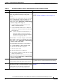
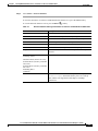
Terminology Differences
Table 1-8 highlights some of the important differences in terminology that is used in these documents:
Table 1-8
•
Cisco Unified IP Phone 6921, 6941, and 6961 User Guide for Cisco Unified Communications
Manager 7.1 (SCCP)
•
Cisco Unified IP Phone 6921, 6941, and 6961 Administration Guide for Cisco Unified
Communications Manager 7.1 (SCCP)
•
Cisco Unified Communications Manager Administration Guide.
•
Cisco Unified Communications Manager System Guide.
Terminology Differences
User Guide
Administration and System Guides
Speed-Dialing (Placing a call with a
speed-dial code)
Abbreviated Dialing
Conference across Lines
Join Across Lines
Conference
Join or Conference
Line Status
Busy Lamp Field (BLF)
Message Indicators
Message Waiting Indicator (MWI) or
Message Waiting Lamp
Programmable Feature Button
Programmable Line Button or
Programmable Line Key (PLK)
Voicemail System
Voice Messaging System
Cisco Unified IP Phone 6921, 6941, and 6961 Administration Guide for Cisco Unified Communications Manager 7.1 (SCCP)
1-20
OL-19025-01
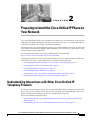
CH A P T E R
2
Preparing to Install the Cisco Unified IP Phone on
Your Network
Cisco Unified IP Phones enable you to communicate by using voice over a data network. To provide this
capability, the IP Phones depend upon and interact with several other key Cisco Unified IP Telephony
components, including Cisco Unified Communications Manager.
This chapter focuses on the interactions between the Cisco Unified IP Phone 6921, 6941, and 6961 and
Cisco Unified Communications Manager, DNS and DHCP servers, TFTP servers, and switches. It also
describes options for powering phones.
For related information about voice and IP communications, refer to this URL:
http://www.cisco.com/en/US/products/sw/voicesw/index.html
This chapter provides an overview of the interaction between the Cisco Unified IP Phone and other key
components of the Voice over IP (VoIP) network. It includes the following topics:
•
Understanding Interactions with Other Cisco Unified IP Telephony Products, page 2-1
•
Providing Power to the Cisco Unified IP Phone, page 2-3
•
Understanding Phone Configuration Files, page 2-5
•
Understanding the Phone Startup Process, page 2-6
•
Adding Phones to the Cisco Unified Communications Manager Database, page 2-7
•
Determining the MAC Address for a Cisco Unified IP Phone, page 2-10
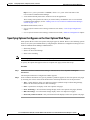
Understanding Interactions with Other Cisco Unified IP
Telephony Products
To function in the IP telephony network, the Cisco Unified IP Phone must be connected to a networking
device, such as a Cisco Catalyst switch. You must also register the Cisco Unified IP Phone with a Cisco
Unified Communications Manager system before sending and receiving calls.
This section includes the following topics:
•
Understanding How the Cisco Unified IP Phone Interacts with Cisco Unified Communications
Manager, page 2-2
•
Understanding How the Cisco Unified IP Phone Interacts with the VLAN, page 2-2
Cisco Unified IP Phone 6921, 6941, and 6961 Administration Guide for Cisco Unified Communications Manager 7.1 (SCCP)
OL-19025-01
2-1
Chapter 2
Understanding Interactions with Other Cisco Unified IP Telephony Products
Preparing to Install the Cisco Unified IP Phone on Your Network
Understanding How the Cisco Unified IP Phone Interacts with Cisco Unified
Communications Manager
Cisco Unified Communications Manager is an open and industry-standard call processing system.
Cisco Unified Communications Manager software sets up and tears down calls between phones,
integrating traditional PBX functionality with the corporate IP network. Cisco Unified Communications
Manager manages the components of the IP telephony system—the phones, theaccess gateways, and the
resources necessary for features such as call conferencing and route planning. Cisco Unified
Communications Manager also provides:
•
Firmware for phones
•
Configuration file via TFTP service
•
Phone registration
•
Call preservation, so that a media session continues if signaling is lost between the primary
Communications Manager and a phone
For information about configuring Cisco Unified Communications Manager to work with the IP devices
described in this chapter, go to the Cisco Unified IP Phone Configuration chapter in the Cisco Unified
Communications Manager Administration Guide.
For an overview of security functionality for the Cisco Unified IP Phone, see the “Understanding
Security Features for Cisco Unified IP Phones” section on page 1-13.
Note
If the Cisco Unified IP Phone model that you want to configure does not appear in the Phone Type
drop-down list in Cisco Unified Communications Manager Administration, go to the following URL and
install the latest support patch for your version of Cisco Unified Communications Manager:
http://www.cisco.com/cisco/software/navigator.html?mdfid=268439621&catid=2788752
40
For more information, refer to “Software Upgrades” chapter in the Cisco Unified Communications
Operating System Administration Guide.
Related Topic
•
Telephony Features Available for the Cisco Unified IP Phone, page 5-1
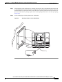
Understanding How the Cisco Unified IP Phone Interacts with the VLAN
The Cisco Unified IP Phone 6921, 6941, and 6961 have an internal Ethernet switch, enabling forwarding
of packets to the phone, and to the access port and the network port on the back of the phone.
If a computer is connected to the access port, the computer and the phone share the same physical link
to the switch and share the same port on the switch. This shared physical link has the following
implications for the VLAN configuration on the network:
•
The current VLANs might be configured on an IP subnet basis. However, additional IP addresses
might not be available to assign the phone to the same subnet as other devices connected to the same
port.
•
Data traffic present on the VLAN supporting phones might reduce the quality of Voice-over-IP
traffic.
•
Network security may indicate a need to isolate the VLAN voice traffic from the VLAN data traffic.
Cisco Unified IP Phone 6921, 6941, and 6961 Administration Guide for Cisco Unified Communications Manager 7.1 (SCCP)
2-2
OL-19025-01
Chapter 2
Preparing to Install the Cisco Unified IP Phone on Your Network
Providing Power to the Cisco Unified IP Phone
You can resolve these issues by isolating the voice traffic onto a separate VLAN. The switch port that
the phone is connected to would be configured to have separate VLANs for carrying:
•
Voice traffic to and from the IP phone (auxiliary VLAN on the Cisco Catalyst 6000 series, for
example)
•
Data traffic to and from the PC connected to the switch through the access port of the IP phone
(native VLAN)
Isolating the phones on a separate, auxiliary VLAN increases the quality of the voice traffic and allows
a large number of phones to be added to an existing network where there are not enough IP addresses
for each phone.
For more information, refer to the documentation included with a Cisco switch. You can also access
switch information at this URL:
http://cisco.com/en/US/products/hw/switches/index.html
Related Topics
•
Understanding the Phone Startup Process, page 2-6
•
Network Setup Menu, page 4-4
Providing Power to the Cisco Unified IP Phone
The Cisco Unified IP Phone 6921, 6941, and 6961 can be powered with external power or with Power
over Ethernet (PoE). External power is provided through a separate power supply. PoE is provided by a
switch through the Ethernet cable attached to a phone.
Note
When you install a phone that is powered with external power, connect the power supply to the phone
and to a power outlet before you connect the Ethernet cable to the phone. When you remove a phone that
is powered with external power, disconnect the Ethernet cable from the phone before you disconnect the
power supply.
The following sections provide more information about powering a phone:
•
Power Guidelines, page 2-4
•
Power Outage, page 2-4
•
Obtaining Additional Information about Power, page 2-5
Cisco Unified IP Phone 6921, 6941, and 6961 Administration Guide for Cisco Unified Communications Manager 7.1 (SCCP)
OL-19025-01
2-3
Chapter 2
Preparing to Install the Cisco Unified IP Phone on Your Network
Providing Power to the Cisco Unified IP Phone
Power Guidelines
Table 2-1 provides guidelines for powering the Cisco Unified IP Phone 6921, 6941, and 6961.
Table 2-1
Guidelines for Powering the Cisco Unified IP Phone 6921, 6941, and 6961
Power Type
Guidelines
External power—Provided
through the CP-PWR-CUBE-3
external power supply.
The Cisco Unified IP Phone 6921, 6941, and 6961 use the CP-PWR-CUBE-3 power
supply.
External power—Provided
through the Cisco Unified IP
Phone Power Injector.
The Cisco Unified IP Phone Power Injector may be used with any Cisco Unified IP Phone.
Functioning as a midspan device, the injector delivers inline power to the attached phone.
The Cisco Unified IP Phone Power Injector is connected between a switch port and the IP
Phone, and supports a maximum cable length of 100m between the unpowered switch and
the IP Phone.
PoE power—Provided by a
switch through the Ethernet
cable attached to the phone.
External power—Provided
through inline power patch
panel WS-PWR-PANEL
•
The Cisco Unified IP Phone 6921, 6941, and 6961 support Cisco inline PoE.
•
The Cisco Unified IP Phone 6921, 6941, and 6961 support IEEE 802.3af Class 2
power on signal pairs and spare pairs.
•
To ensure uninterruptible operation of the phone, make sure that the switch has a
backup power supply.
•
Make sure that the CatOS or IOS version running on your switch supports your
intended phone deployment. Refer to the documentation for your switch for operating
system version information.
The inline power patch panel WS-PWR-PANEL is compatible with the Cisco Unified
IP Phone 6921, 6941, and 6961.
Power Outage
Your accessibility to emergency service through the phone is dependent on the phone being powered. If
there is an interruption in the power supply, Service and Emergency Calling Service dialing will not
function until power is restored. In the case of a power failure or disruption, you may need to reset or
reconfigure equipment before using the Service or Emergency Calling Service dialing.
Cisco Unified IP Phone 6921, 6941, and 6961 Administration Guide for Cisco Unified Communications Manager 7.1 (SCCP)
2-4
OL-19025-01
Chapter 2
Preparing to Install the Cisco Unified IP Phone on Your Network
Understanding Phone Configuration Files
Obtaining Additional Information about Power
For related information about power, refer to the documents shown in Table 2-2. These documents
provide information about the following topics:
•
Cisco switches that work with the Cisco Unified IP Phone 6921, 6941, and 6961
•
The Cisco IOS releases that support bidirectional power negotiation
•
Other requirements and restrictions regarding power
Table 2-2
Related Documentation for Power
Document Topics
URL
Cisco Unified IP Phone Power
Injector
http://www.cisco.com/en/US/products/ps6951/index.html
PoE Solutions
http://www.cisco.com/en/US/netsol/ns340/ns394/ns147/ns412/net
working_solutions_package.html
Cisco Catalyst Switches
http://cisco.com/en/US/products/hw/switches/index.html
Integrated Service Routers
http://www.cisco.com/en/US/products/hw/routers/index.html
Cisco IOS Software
http://www.cisco.com/en/US/products/sw/iosswrel/products_ios_
cisco_ios_software_category_home.html
Understanding Phone Configuration Files
Configuration files for a phone are stored on the TFTP server and define parameters for connecting to
Cisco Unified Communications Manager. In general, any time you make a change in Cisco Unified
Communications Manager that requires the phone to be reset, a change is automatically made to the
phone’s configuration file.
Configuration files also contain information about which image load the phone should be running. If this
image load differs from the one currently loaded on a phone, the phone contacts the TFTP server to
request the required load files.
A phone accesses a default configuration file named XmlDefault.cnf.xml from the TFTP server when
the following conditions exist:
•
You have enabled auto-registration in Cisco Unified Communications Manager
•
The phone has not been added to the Cisco Unified Communications Manager database
•
The phone is registering for the first time
If auto registration is not enabled and the phone has not been added to the Cisco Unified
Communications Manager database, the phone registration request will be rejected and display a blank
screen.
If the phone has registered before, the phone will access the configuration file named
SEPmac_address.cnf.xml, where mac_address is the MAC address of the phone.
The filenames are derived from the MAC address and description fields in the Phone Configuration
window of Cisco Unified Communications Manager Administration. The MAC address uniquely
identifies the phone.
For more information on phone configuration settings, go to the Cisco Unified IP Phone Configuration
chapter in the Cisco Unified Communications Manager Administration Guide.
Cisco Unified IP Phone 6921, 6941, and 6961 Administration Guide for Cisco Unified Communications Manager 7.1 (SCCP)
OL-19025-01
2-5
Chapter 2
Preparing to Install the Cisco Unified IP Phone on Your Network
Understanding the Phone Startup Process
Understanding the Phone Startup Process
When connecting to the VoIP network, the Cisco Unified IP Phone 6921, 6941, and 6961 go through a
standard startup process that is described in Table 2-3. Depending on your specific network
configuration, not all of these steps may occur on your Cisco Unified IP Phone.
Table 2-3
Task
1.
Cisco Unified IP Phone Startup Process
Purpose
Obtaining Power from the Switch
•
If a phone is not using external power, the switch
provides in-line power through the Ethernet cable
attached to the phone.
Adding Phones to the Cisco Unified
Communications Manager Database, page 2-7.
•
Resolving Startup Problems, page 9-1.
Loading the Stored Phone Image
2.
Related Topics
Resolving Startup Problems, page 9-1.
The Cisco Unified IP Phone has non-volatile Flash
memory in which it stores firmware images and
user-defined preferences. At startup, the phone runs a
bootstrap loader that loads a phone image stored in
Flash memory. Using this image, the phone initializes
its software and hardware.
3.
4.
5.
Configuring VLAN
•
Network Setup Menu, page 4-4.
If the Cisco Unified IP Phone is connected to a
Cisco Catalyst switch, the switch next informs the
phone of the voice VLAN defined on the switch. The
phone needs to know its VLAN membership before it
can proceed with the Dynamic Host Configuration
Protocol (DHCP) request for an IP address.
•
Resolving Startup Problems, page 9-1.
Obtaining an IP Address
•
Network Setup Menu, page 4-4.
If the Cisco Unified IP Phone is using DHCP to obtain
an IP address, the phone queries the DHCP server to
obtain one. If you are not using DHCP in your
network, you must assign static IP addresses to each
phone locally.
•
Resolving Startup Problems, page 9-1.
Accessing a TFTP Server
•
Network Setup Menu, page 4-4.
In addition to assigning an IP address, the DHCP
server directs the Cisco Unified IP Phone to a TFTP
Server. If the phone has a statically defined IP address,
you must configure the TFTP server locally on the
phone; the phone then contacts the TFTP server
directly.
•
Resolving Startup Problems, page 9-1.
Note
You can also assign an alternative TFTP server
to use instead of the one assigned by DHCP.
Cisco Unified IP Phone 6921, 6941, and 6961 Administration Guide for Cisco Unified Communications Manager 7.1 (SCCP)
2-6
OL-19025-01
Chapter 2
Preparing to Install the Cisco Unified IP Phone on Your Network
Adding Phones to the Cisco Unified Communications Manager Database
Table 2-3
Task
6.
Cisco Unified IP Phone Startup Process (continued)
Purpose
Related Topics
Requesting the Configuration File
The TFTP server has configuration files, which define
parameters for connecting to Cisco
Unified Communications Manager and other
information for the phone.
7.
Contacting Cisco Unified Communications Manager
•
Adding Phones to the Cisco Unified
Communications Manager Database, page 2-7.
•
Resolving Startup Problems, page 9-1.
Resolving Startup Problems, page 9-1.
The configuration file defines how the Cisco
Unified IP Phone communicates with Cisco
Unified Communications Manager and provides a
phone with its load ID. After obtaining the file from
the TFTP server, the phone attempts to make a
connection to the highest priority Cisco
Unified Communications Manager on the list.
If the phone was manually added to the database,
Cisco Unified Communications Manager identifies
the phone. If the phone was not manually added to the
database and auto-registration is enabled in Cisco
Unified Communications Manager, the phone
attempts to auto-register itself in the Cisco
Unified Communications Manager database.
Adding Phones to the Cisco Unified Communications Manager
Database
Before installing the Cisco Unified IP phone, you must choose a method for adding phones to the
Cisco Unified Communications Manager database. Be aware that each phone type requires a fixed
number of device license units and the number of unit licenses that are available on the server may
impact phone registration. For more information on licensing go to the Licenses for Phones section in
the Cisco Unified Communications Manager System Guide
These sections describe the methods:
•
Adding Phones with Auto-Registration, page 2-8
•
Adding Phones with Auto-Registration and TAPS, page 2-9
•
Adding Phones with Cisco Unified Communications Manager Administration, page 2-9
•
Adding Phones with BAT, page 2-10
Cisco Unified IP Phone 6921, 6941, and 6961 Administration Guide for Cisco Unified Communications Manager 7.1 (SCCP)
OL-19025-01
2-7
Chapter 2
Preparing to Install the Cisco Unified IP Phone on Your Network
Adding Phones to the Cisco Unified Communications Manager Database
Table 2-4 provides an overview of these methods for adding phones to the Cisco Unified
Communications Manager database.
Table 2-4
Methods for Adding Phones to the Cisco Unified Communications Manager
Database
Method
Requires MAC
Address?
Auto-registration
No
Results in automatic assignment of directory
numbers
Auto-registration with
TAPS
No
Requires auto-registration and the Bulk
Administration Tool (BAT); updates information
in the Cisco Unified IP Phone and in Cisco
Unified Communications Manager Administration
Notes
Yes
Using the Cisco Unified
Communications Manager
Administration
Requires phones to be added individually
Using BAT
Allows for simultaneous registration of multiple
phones
Yes
Adding Phones with Auto-Registration
By enabling auto-registration before you begin installing phones, you can:
Note
•
Add phones without first gathering MAC addresses from the phones.
•
Automatically add a Cisco Unified IP Phone to the Cisco Unified Communications Manager
database when you physically connect the phone to your IP telephony network. During
auto-registration, Cisco Unified Communications Manager assigns the next available sequential
directory number to the phone.
•
Quickly enter phones into the Cisco Unified Communications Manager database and modify any
settings, such as the directory numbers, from Cisco Unified Communications Manager.
•
Move auto-registered phones to new locations and assign them to different device pools without
affecting their directory numbers.
Cisco recommends you use auto-registration to add less than 100 phones to your network. To add more
than 100 phones to your network, use the Bulk Administration Tool (BAT). See the “Adding Phones with
BAT” section on page 2-10.
Auto-registration is disabled by default. In some cases, you might not want to use auto-registration; for
example, if you want to assign a specific directory number to the phone. For information about enabling
auto-registration, go to the “Enabling Auto-Registration” section in the Cisco Unified Communications
Manager Administration Guide.
Note
When you configure the cluster for mixed mode through the Cisco CTL client, auto-registration is
automatically disabled. When you configure the cluster for non-secure mode through the Cisco CTL
client, auto-registration is automatically enabled.
Cisco Unified IP Phone 6921, 6941, and 6961 Administration Guide for Cisco Unified Communications Manager 7.1 (SCCP)
2-8
OL-19025-01
Chapter 2
Preparing to Install the Cisco Unified IP Phone on Your Network
Adding Phones to the Cisco Unified Communications Manager Database
Related Topics
•
Adding Phones with Auto-Registration and TAPS, page 2-9
•
Adding Phones with Cisco Unified Communications Manager Administration, page 2-9
•
Adding Phones with BAT, page 2-10
Adding Phones with Auto-Registration and TAPS
You can add phones with auto-registration and TAPS, the Tool for Auto-Registered Phones Support,
without first gathering MAC addresses from phones.
TAPS works with the Bulk Administration Tool (BAT) to update a batch of phones that were already
added to the Cisco Unified Communications Manager database with dummy MAC addresses. Use TAPS
to update MAC addresses and download pre-defined configurations for phones.
Note
Cisco recommends you use auto-registration and TAPS to add less than 100 phones to your network. To
add more than 100 phones to your network, use the Bulk Administration Tool (BAT). See the “Adding
Phones with BAT” section on page 2-10.
To implement TAPS, you or the end-user dial a TAPS directory number and follow voice prompts. When
the process is complete, the phone will have downloaded its directory number and other settings, and the
phone will be updated in Cisco Unified Communications Manager Administration with the correct MAC
address.
Auto-registration must be enabled in Cisco Unified Communications Manager Administration
(System > Cisco Unified CM) for TAPS to function.
Note
When you configure the cluster for mixed mode through the Cisco CTL client, auto-registration is
automatically disabled. When you configure the cluster for non-secure mode through the Cisco CTL
client, auto-registration is automatically enabled.
For more information, go to the “Bulk Administration” chapter in Cisco Unified Communications
Manager Administration Guide.
Related Topics
•
Adding Phones with Auto-Registration, page 2-8
•
Adding Phones with Cisco Unified Communications Manager Administration, page 2-9
•
Adding Phones with BAT, page 2-10
Adding Phones with Cisco Unified Communications Manager Administration
You can add phones individually to the Cisco Unified Communications Manager database by using
Cisco Unified Communications Manager Administration. To do so, you first need to obtain the MAC
address for each phone.
For information about determining a MAC address, see the “Determining the MAC Address for a Cisco
Unified IP Phone” section on page 2-10.
Cisco Unified IP Phone 6921, 6941, and 6961 Administration Guide for Cisco Unified Communications Manager 7.1 (SCCP)
OL-19025-01
2-9
Chapter 2
Preparing to Install the Cisco Unified IP Phone on Your Network
Determining the MAC Address for a Cisco Unified IP Phone
After you have collected MAC addresses, in Cisco Unified Communications Manager Administration,
choose Device > Phone and click Add New to begin.
For complete instructions and conceptual information about Cisco Unified Communications Manager,
go to the “Cisco Unified Communications Manager Overview” chapter in the Cisco Unified
Communications Manager System Guide.
Related Topics
•
Adding Phones with Auto-Registration, page 2-8
•
Adding Phones with Auto-Registration and TAPS, page 2-9
•
Adding Phones with BAT, page 2-10
Adding Phones with BAT
Cisco Unified Communications Manager Bulk Administration Tool (BAT) enables you to perform batch
operations, including registration, on multiple phones. To access BAT, choose Bulk Administration
drop-down menu in Cisco Unified Communications Manager Administration,
To add phones by using BAT only (not in conjunction with TAPS), you can use the MAC address for
each phone or dummy MAC addresses if you have a large number of new phones.
For information about determining a MAC address, see the “Determining the MAC Address for a Cisco
Unified IP Phone” section on page 2-10.
For detailed instructions about using BAT, go to the “Bulk Administration” chapter in the Cisco Unified
Communications Manager Administration Guide.
Related Topics
•
Adding Phones with Auto-Registration, page 2-8
•
Adding Phones with Auto-Registration and TAPS, page 2-9
•
Adding Phones with Cisco Unified Communications Manager Administration, page 2-9
Determining the MAC Address for a Cisco Unified IP Phone
Several procedures described in this manual require you to determine the MAC address of a
Cisco Unified IP Phone. You can determine a phone’s MAC address in these ways:
•
From the phone, press the Applications button and select Phone Information and look at the
MAC Address field.
•
Look at the MAC label on the back of the phone.
•
Display the web page for the phone and click the Device Information hyperlink.
For information about accessing the web page, see the “Accessing the Web Page for a Phone”
section on page 8-2.
Cisco Unified IP Phone 6921, 6941, and 6961 Administration Guide for Cisco Unified Communications Manager 7.1 (SCCP)
2-10
OL-19025-01
CH A P T E R
3
Setting Up the Cisco Unified IP Phone
This chapter includes the following topics, which help you install the Cisco Unified IP Phone on an IP
telephony network:
Note
•
Before You Begin, page 3-1
•
Understanding the Cisco Unified IP Phone 6921, 6941, and 6961 Components, page 3-2
•
Installing the Cisco Unified IP Phone, page 3-5
•
Footstand, page 3-8
•
Reducing Power Consumption on the Phone, page 3-8
•
Verifying the Phone Startup Process, page 3-12
•
Configuring Startup Network Settings, page 3-13
Before you install a Cisco Unified IP phone, you must decide how to configure the phone in your
network. Then you can install the phone and verify its functionality. For more information, see
Chapter 2, “Preparing to Install the Cisco Unified IP Phone on Your Network.”
Before You Begin
Before installing the Cisco Unified IP Phone, review the requirements in these sections:
•
Network Requirements, page 3-1
•
Cisco Unified Communications Manager Configuration, page 3-2
Network Requirements
For the Cisco Unified IP Phone to successfully operate as a Cisco Unified IP Phone endpoint in your
network, your network must meet the following requirements:
•
Working Voice over IP (VoIP) Network:
– VoIP configured on your Cisco routers and gateways
– Cisco Unified Communications Manager installed in your network and configured to handle
call processing
•
IP network that supports DHCP or manual assignment of IP address, gateway, and subnet mask
Cisco Unified IP Phone 6921, 6941, and 6961 Administration Guide for Cisco Unified Communications Manager 7.1 (SCCP)
OL-19025-01
3-1
Chapter 3
Setting Up the Cisco Unified IP Phone
Understanding the Cisco Unified IP Phone 6921, 6941, and 6961 Components
Note
The Cisco Unified IP Phone displays the date and time from Cisco Unified Communications Manager.
If the Cisco Unified Communications Manager server is located in a different time zone than the phones,
the phones will not display the correct local time.
Cisco Unified Communications Manager Configuration
The Cisco Unified IP Phone requires Cisco Unified Communications Manager to handle call
processing. Refer to Cisco Unified Communications Manager Administration Guide or to
context-sensitive help in the Cisco Unified Communications Manager application to ensure that
Cisco Unified Communications Manager is set up properly to manage the phone and to properly route
and process calls.
If you plan to use auto-registration, verify that it is enabled and properly configured in Cisco Unified
Communications Manager Administration before connecting any Cisco Unified IP Phone to the
network. For information about enabling and configuring auto-registration, refer to Cisco
Unified Communications Manager Administration Guide. Also, see the “Adding Phones to the Cisco
Unified Communications Manager Database” section on page 2-7.
You must use Cisco Unified Communications Manager Administration to configure and assign
telephony features to the Cisco Unified IP Phones. See the “Telephony Features Available for the Cisco
Unified IP Phone” section on page 5-1 for details.
In Cisco Unified Communications Manager Administration, you can add users to the database, add users
to user groups, and associate users to specific phones. In this way, users gain access their Cisco Unified
CM User Option page to configure items such as call forwarding, speed dialing, and voice messaging
system options. See the “Adding Users to Cisco Unified Communications Manager” section on
page 5-19 for details.
Understanding the Cisco Unified IP Phone 6921, 6941, and 6961
Components
The Cisco Unified IP Phone 6921, 6941, and 6961 include these components on the phone or as
accessories for the phone:
•
Network and Access Ports, page 3-2
•
Handset, page 3-3
•
Speakerphone, page 3-3
•
Headset, page 3-3
Network and Access Ports
The back of the Cisco Unified IP Phone 6921, 6941, and 6961 includes these ports:
•
Network port
– labeled Network
•
Access port
Cisco Unified IP Phone 6921, 6941, and 6961 Administration Guide for Cisco Unified Communications Manager 7.1 (SCCP)
3-2
OL-19025-01
Chapter 3
Setting Up the Cisco Unified IP Phone
Understanding the Cisco Unified IP Phone 6921, 6941, and 6961 Components
– labeled Computer
Each port supports 10/100 Mbps half- or full-duplex connections to external devices. You can use either
Category 3/5/5e cabling for 10-Mbps connections, but you must use Category 5/5e for 100 Mbps
connections.
Use the SW network port to connect the phone to the network. You must use a straight-through cable on
this port. The phone can also obtain inline power from a switch over this connection. See the “Adding
Phones to the Cisco Unified Communications Manager Database” section on page 2-7 for details.
Use the PC access port to connect a network device, such as a computer, to the phone. You must use a
straight-through cable on this port.
Handset
The handset is designed especially for use with a Cisco Unified IP Phone. It includes a light strip that
indicates incoming calls and voice messages waiting.
To connect a handset to the Cisco Unified IP Phone, plug the cable into the handset and the Handset port
on the back of the phone.
Speakerphone
By default, the speakerphone is enabled on the Cisco Unified IP Phone.
You can disable the speakerphone by using Cisco Unified Communications Manager Administration. To
do so, choose Device > Phone and locate the phone you want to modify. In the Phone Configuration
window for the phone, check the Disable Speakerphone check box.
Headset
Although Cisco Systems performs internal testing of third-party headsets for use with the Cisco Unified
IP Phones, Cisco Systems does not certify or support products from headset or handset vendors.
Cisco recommends the use of good quality external devices, for example, headsets that are screened
against unwanted radio frequency (RF) and audio frequency (AF) signals. Depending on the quality of
headsets and their proximity to other devices such as cell phones and two-way radios, some audio noise
or echo may still occur. An audible hum or buzz may be heard by either the remote party or by both the
remote party and the Cisco Unified IP Phone user. Humming or buzzing sounds can be caused by a range
of outside sources; for example, electric lights, electric motors, or large PC monitors. See the “Using
External Devices” section on page 3-4 for more information.
Note
In some cases, hum may be reduced or eliminated by using a local power cube or power injector.
These environmental and hardware inconsistencies in the locations where Cisco Unified IP Phones are
deployed means that there is not a single headset solution that is optimal for all environments.
Cisco recommends that customers test headsets in their intended environment to determine performance
before making a purchasing decision and deploying en masse.
Cisco Unified IP Phone 6921, 6941, and 6961 Administration Guide for Cisco Unified Communications Manager 7.1 (SCCP)
OL-19025-01
3-3
Chapter 3
Setting Up the Cisco Unified IP Phone
Understanding the Cisco Unified IP Phone 6921, 6941, and 6961 Components
Audio Quality
Beyond the physical, mechanical and technical performance, the audio portion of a headset must sound
good to the user and to the party on the far end. Sound quality is subjective and Cisco cannot guarantee
the performance of any headsets. However, a variety of headsets from leading headset manufacturers
have been reported to perform well with Cisco Unified IP Phones.
For information about wireless headsets that work in conjunction with the wireless headset remote
hookswitch control feature, go to the following URL:
http://www.cisco.com/en/US/partner/prod/voicesw/ucphone_headsets.html.
Connecting a Headset
To connect a wired headset to the Cisco Unified IP Phone, plug it into the Headset port on the back of
the phone. Press the Headset button on the phone to place and answer calls using the headset.
You can use the wired headset with all of the features on the Cisco Unified IP Phone, including the
Volume and Mute buttons. Use these buttons to adjust the ear piece volume and to mute the speech path
from the headset microphone.
Disabling a Headset
You can disable the headset by using Cisco Unified Communications Manager Administration. If you
do so, you also will disable the speakerphone.
To disable the headset from Cisco Unified Communications Manager Administration, choose Device >
Phone and locate the phone that you want to modify. In the Phone Configuration window for the phone,
check the Disable Speakerphone and Headset check box.
Using External Devices
The following information applies when you use external devices with the Cisco Unified IP Phone:
Cisco recommends the use of good quality external devices that are shielded (screened) against
unwanted radio frequency (RF) and audio frequency (AF) signals.
Depending on the quality of these devices and their proximity to other devices such as mobile phones or
two-way radios, some audio noise may still occur. In these cases, Cisco recommends that you take one
or more of the following actions:
•
Move the external device away from the source of the RF or AF signals.
•
Route the external device cables away from the source of the RF or AF signals.
•
Use shielded cables for the external device, or use cables with a better shield and connector.
•
Shorten the length of the external device cable.
•
Apply ferrites or other such devices on the cables for the external device.
Cisco cannot guarantee the performance of the system because Cisco has no control over the quality of
external devices, cables, and connectors. The system will perform adequately when suitable devices are
attached using good quality cables and connectors.
Caution
In European Union countries, use only external headsets that are fully compliant with the EMC Directive
[89/336/EC].
Cisco Unified IP Phone 6921, 6941, and 6961 Administration Guide for Cisco Unified Communications Manager 7.1 (SCCP)
3-4
OL-19025-01
Chapter 3
Setting Up the Cisco Unified IP Phone
Installing the Cisco Unified IP Phone
Installing the Cisco Unified IP Phone
You must connect the Cisco Unified IP Phone to the network and to a power source before using it. See
Figure 3-1 for a graphical representation of the connections for a Cisco Unified IP Phone 6921 and 6941
and Figure 3-2 for a graphical representation of the connections for a Cisco Unified IP Phone 6961.
Note
Before you install a phone, even if it is new, upgrade the phone to the current firmware image. Before
using external devices, read the “Using External Devices” section on page 3-4 for safety and
performance information.
To install a Cisco Unified IP Phone, perform the tasks described in Table 3-1.
Table 3-1
Task
Installing the Cisco Unified IP Phone 6921, 6941, and 6961
Purpose
Related Topics
1.
Connect the handset to the Handset port.
—
2.
Connect a headset to the Headset port.
See the “Headset” section on page 3-3 for supported
headsets.
Optional. You can add a headset later if you do not
connect one now.
3.
Optional. Connect the power supply to the Cisco DC See the “Adding Phones to the Cisco Unified
Adapter port.
Communications Manager Database” section on
page 2-7 for guidelines.
4.
Connect a straight-through Ethernet cable from the
switch to the network port labeled Network on the
Cisco Unified IP Phone 6921, 6941, and 6961.
See the “Network and Access Ports” section on page 3-2
for guidelines.
Each Cisco Unified IP Phone ships with one Ethernet
cable in the box.
You can use either Category 3/5/5e cabling for
10-Mbps connections, but you must use Category 5/5e
for 100 Mbps connections.
5.
Connect a straight-through Ethernet cable from
another network device, such as a desktop computer,
to the access port labeled Computer on the
Cisco Unified IP Phone 6921, 6941, and 6961.
See the “Network and Access Ports” section on page 3-2
for guidelines.
Optional. You can connect another network device
later if you do not connect one now.
You can use either Category 3/5/5e cabling for
10-Mbps connections, but you must use Category 5/5e
for 100 Mbps connections.
Cisco Unified IP Phone 6921, 6941, and 6961 Administration Guide for Cisco Unified Communications Manager 7.1 (SCCP)
OL-19025-01
3-5
Chapter 3
Setting Up the Cisco Unified IP Phone
Installing the Cisco Unified IP Phone
Figure 3-1
Cisco Unified IP Phone 6921 and 6941 Cable Connections
1
3
7
2
6
4
192762
5
Cisco Unified IP Phone 6921, 6941, and 6961 Administration Guide for Cisco Unified Communications Manager 7.1 (SCCP)
3-6
OL-19025-01
Chapter 3
Setting Up the Cisco Unified IP Phone
Installing the Cisco Unified IP Phone
Figure 3-2
Cisco Unified IP Phone 6961 Cable Connections
1
3
7
2
6
192617
5
4
1
DC adaptor port (DC48V)
5
Access port (10/100 PC) connection
2
AC-to-DC power supply (optional)
6
Handset connection
3
AC power wall plus (optional)
7
Analog headset connection (optional)
4
Network port (10/100 SW) connection. IEEE
802.3af power enabled
8
Related Topics
•
Footstand, page 3-8
•
Verifying the Phone Startup Process, page 3-12
•
Configuring Startup Network Settings, page 3-13
Cisco Unified IP Phone 6921, 6941, and 6961 Administration Guide for Cisco Unified Communications Manager 7.1 (SCCP)
OL-19025-01
3-7
Chapter 3
Setting Up the Cisco Unified IP Phone
Reducing Power Consumption on the Phone
Reducing Power Consumption on the Phone
You can reduce the amount of energy that the Cisco Unified IP Phone 6921, 6941, and 6961 consumes
by scheduling when the phone goes into power save mode. In power save mode, the backlight on the
screen is not lit when the phone is not in use. The phone remains in power save mode for the scheduled
duration or until the user lifts the handset or presses any button. In the Phone Configuration page on
Cisco Unified Communications Administration, configure the following parameters.
•
Days Backlight Not Active—Specify the days that the backlight remains inactive.
•
Backlight on Time—Schedule the time of day that the backlight automatically activates. on the days
listed in the off schedule.
•
Backlight on Duration—Indicates the length of time that the backlight is active once the backlight
is enabled by the programmed schedule
•
Backlight Idle Timeout—Defines the period of user inactivity on the phone before the backlight is
turned off.
Footstand
If your phone is placed on a table or desk, the footstand can be connected to the back of the phone for a
higher or lower viewing angle, depending on your preference.
Figure 3-3 illustrates the footstand and the alignment of the tabs on the footstand with the two different
sets of holes on the Cisco Unified IP Phone 6921 and 6941. Figure 3-4 illustrates the footstand and the
alignment of the tabs on the footstand with the two different sets of holes on the Cisco Unified IP Phone
6961.
Cisco Unified IP Phone 6921, 6941, and 6961 Administration Guide for Cisco Unified Communications Manager 7.1 (SCCP)
3-8
OL-19025-01
Chapter 3
Setting Up the Cisco Unified IP Phone
Footstand
Figure 3-3
Cisco Unified IP Phone 6921 and 6941
2
194407
1
1
Footstand slots for a higher viewing angle
2
Footstand slots for a lower viewing angle
Cisco Unified IP Phone 6921, 6941, and 6961 Administration Guide for Cisco Unified Communications Manager 7.1 (SCCP)
OL-19025-01
3-9
Chapter 3
Setting Up the Cisco Unified IP Phone
Footstand
Figure 3-4
Cisco Unified IP Phone 6961
2
1
194406
CISCO
1
Footstand slots for a higher viewing angle
2
Footstand slots for a lower viewing angle
Cisco Unified IP Phone 6921, 6941, and 6961 Administration Guide for Cisco Unified Communications Manager 7.1 (SCCP)
3-10
OL-19025-01
Chapter 3
Setting Up the Cisco Unified IP Phone
Footstand
195159
Higher Viewing Angle
Cisco Unified IP Phone 6921, 6941, and 6961 Administration Guide for Cisco Unified Communications Manager 7.1 (SCCP)
OL-19025-01
3-11
Chapter 3
Setting Up the Cisco Unified IP Phone
Mounting the Phone to the Wall
195160
Lower Viewing Angle
Mounting the Phone to the Wall
You can mount the Cisco Unified IP Phone on the wall by using special brackets available in a
Cisco Unified IP Phone wall mount kit. For information on installing the wall mount kit, see
Appendix E, “Installing the Wall Mount Kit for the Cisco Unified IP Phone 6921, 6941, and 6961” or
Appendix F, “Cisco Unified IP Phone Non-Lockable Wall Mount.”
Note
Wall mount kits are ordered separately from the phone.
Verifying the Phone Startup Process
After the Cisco Unified IP Phone has power connected to it, the phone begins its startup diagnostic
process by cycling through the following steps.
1.
The following LED buttons flash on and off during the various stages of bootup as the phone checks
its hardware. See Table 3-2 for a list of the hardware test and the LED diagnostic status.
Cisco Unified IP Phone 6921, 6941, and 6961 Administration Guide for Cisco Unified Communications Manager 7.1 (SCCP)
3-12
OL-19025-01
Chapter 3
Setting Up the Cisco Unified IP Phone
Configuring Startup Network Settings
Table 3-2
LED Diagnostic Status
Hardware Test
MWI
Hold
Mute
Speaker
Power is Ready
On
On
On
On
Flash is Accessible
—
On
On
On
RAM Test Successful
—
—
On
On
Ethernet Test Successful
—
—
—
On
2.
The screen displays the Cisco Systems, Inc., logo screen.
3.
These messages appear as the phone starts up.
– Configuring IP message
– Registering
4.
The home screen displays:
– Current date and time
– Primary directory number
– Additional directory numbers and speed dial numbers, if configured (Only on Cisco Unified IP
Phone 6961)
– Softkeys
If the phone successfully passes through these stages, it has started up properly. If the phone does not
start up properly, see the “Resolving Startup Problems” section on page 9-1.
Configuring Startup Network Settings
If you are not using DHCP in your network, you must configure these network settings on the
Cisco Unified IP Phone after installing the phone on the network:
•
IP address
•
IP subnet information
•
TFTP server IP address
•
You also may configure the domain name and the DNS server settings, if necessary.
Collect this information and see the instructions in Chapter 4, “Configuring Settings on the Cisco
Unified IP Phone.”
Cisco Unified IP Phone 6921, 6941, and 6961 Administration Guide for Cisco Unified Communications Manager 7.1 (SCCP)
OL-19025-01
3-13
Chapter 3
Setting Up the Cisco Unified IP Phone
Configuring Startup Network Settings
Cisco Unified IP Phone 6921, 6941, and 6961 Administration Guide for Cisco Unified Communications Manager 7.1 (SCCP)
3-14
OL-19025-01
CH A P T E R
4
Configuring Settings on the Cisco Unified IP
Phone
The Cisco Unified IP Phone includes many configurable network settings that you may need to modify
before the phone is functional for your users. You can access these settings, and change some of them,
through menus on the phone. Settings that are display-only on the phone are configured in
Cisco Unified Communications Manager Administration.
This chapter includes the following topics:
•
Configuration Menus on the Cisco Unified IP Phone, page 4-1
•
Network Setup Menu, page 4-4
•
IPv4 Setup Menu Options, page 4-6
Configuration Menus on the Cisco Unified IP Phone
The Cisco Unified IP Phone includes the following configuration menus:
•
Network Configuration—Provides options for viewing and making a variety of network settings.
For more information, see the “Network Setup Menu” section on page 4-4.
•
IPv4 Configuration—A sub-menu of the Network Configuration menu, the IPv4 menu items provide
additional network options for viewing and setting. For more information, see the “IPv4 Setup Menu
Options” section on page 4-6.
Before you can change option settings on the Network Configuration menu, you must unlock options for
editing. See the “Unlocking and Locking Options” section on page 4-3 for instructions.
For information about the keys you can use to edit or change option settings, see the “Editing Values”
section on page 4-3.
You can control whether a phone user has access to phone settings by using the Settings Access field in
the Cisco Unified Communications Manager Administration Phone Configuration window.
Related Topics
•
Displaying a Configuration Menu, page 4-2
•
Unlocking and Locking Options, page 4-3
•
Editing Values, page 4-3
•
Network Setup Menu, page 4-4
•
IPv4 Setup Menu Options, page 4-6
Cisco Unified IP Phone 6921, 6941, and 6961 Administration Guide for Cisco Unified Communications Manager 7.1 (SCCP)
OL-19025-01
4-1
Chapter 4
Configuring Settings on the Cisco Unified IP Phone
Configuration Menus on the Cisco Unified IP Phone
Displaying a Configuration Menu
To display a configuration menu, perform the following steps.
Note
You can control whether a phone has access to the Settings menu or to options on this menu by using the
Settings Access field in the Cisco Unified Communications Manager Administration Phone
Configuration window. The Settings Access field accepts these values:
•
Enabled—Allows access to the Settings menu.
•
Disabled—Prevents access to the Settings menu.
•
Restricted—Allows access to the User Preferences menu and allows volume changes to be saved.
Prevents access to other options on the Settings menu.
If you cannot access an option on the Administrator Settings menu, check the Settings Access field.
Procedure
Step 1
Press the Applications button.
Step 2
Select Admin Settings.
Note
Step 3
Enter the password and then press the Select button. The Admin Settings password is configured in the
Local Phone Unlock Password parameter in the Common Phone Profile Configuration on
Cisco Unified Communications Manager Administration.
Note
Step 4
For information about the Status menu, see Chapter 7, “Viewing Model Information, Status, and
Statistics on the Cisco Unified IP Phone.” For information about the Reset Settings menu, see
Chapter 9, “Troubleshooting and Maintenance.”
Users can access the Admin Settings without entering a password when the Local Phone Unlock
Password parameter is not configured
Perform one of these actions to display the desired menu:
•
Use the navigation bar to select the desired menu and then press the Select button.
•
Use the keypad on the phone to enter the number that corresponds to the menu.
Step 5
To display a submenu repeat Step 4.
Step 6
To exit a menu, press the Exit softkey.
Related Topics
•
Unlocking and Locking Options, page 4-3
•
Editing Values, page 4-3
•
Network Setup Menu, page 4-4
•
IPv4 Setup Menu Options, page 4-6
Cisco Unified IP Phone 6921, 6941, and 6961 Administration Guide for Cisco Unified Communications Manager 7.1 (SCCP)
4-2
OL-19025-01
Chapter 4
Configuring Settings on the Cisco Unified IP Phone
Configuration Menus on the Cisco Unified IP Phone
Unlocking and Locking Options
You can apply a password to the phone so that no changes can be made to the administrative options on
the phone without the password being entered on the Admin Settings phone screen.
To apply a password to the phone, in Cisco Unified Communications Manager administration, navigate
to the Common Phone Profile Configuration window (Device > Device Settings > Common Phone
Profile). Enter a password in the Local Phone Unlock Password option. Apply the password to the
common phone profile that the phone uses.
Related Topics
•
Displaying a Configuration Menu, page 4-2
•
Editing Values, page 4-3
•
Network Setup Menu, page 4-4
•
IPv4 Setup Menu Options, page 4-6
Editing Values
When you edit the value of an option setting, follow these guidelines:
Note
•
Use the keys on the keypad to enter numbers and letters.
•
To enter letters by using the keypad, use a corresponding number key. Press the key one or more
times to display a particular letter. For example, press the 2 key once for “a,” twice quickly for “b,”
and three times quickly for “c.” After you pause, the cursor automatically advances to allow you to
enter the next letter.
•
To enter a period (for example, in an IP address), press * on the keypad.
•
Press the up arrow on the navigation bar to move the cursor to the left most character, and press the
down arrow on the navigation bar to move the cursor to the right most character.
•
Press
•
Press the Cancel softkey before pressing the Save softkey to discard any changes that you have
made.
if you make a mistake. This softkey deletes the character to the left of the cursor.
The Cisco Unified IP Phone provides several methods you can use to reset or restore option settings, if
necessary. For more information, see the “Resetting or Restoring the Cisco Unified IP Phone” section
on page 9-10.
Related Topics
•
Displaying a Configuration Menu, page 4-2
•
Unlocking and Locking Options, page 4-3
•
Network Setup Menu, page 4-4
•
Network Setup Menu, page 4-4
Cisco Unified IP Phone 6921, 6941, and 6961 Administration Guide for Cisco Unified Communications Manager 7.1 (SCCP)
OL-19025-01
4-3
Chapter 4
Configuring Settings on the Cisco Unified IP Phone
Network Setup Menu
Network Setup Menu
The Network Setup menu provides options for viewing and making a variety of network settings.
Table 4-1 describes these options and, where applicable, explains how to change them.
For information about how to access the Network Setup menu, see the “Displaying a Configuration
Menu” section on page 4-2.
For information about the keys you can use to edit options, see the “Editing Values” section on page 4-3.
Table 4-1
Network Setup Menu Options
Option
Description
IPv4 Setup
In the IPv4 Setup submenu, you can do the following:
To Change
Scroll to IPv4 Setup and press
Select.
• Enable or disable the phone to use the IP address that
is assign by the DHCP server.
•
Manually set the IP Address, Subnet Mask, Default
Routers, DNS Server, and Alternate TFTP servers.
For more information on the IPv4 address fields, refer to
Table 4-2.
Host Name
Unique host name that the DHCP server assigned to the
phone.
Domain Name
Name of the Domain Name System (DNS) domain in
which the phone resides.
Operational VLAN ID
Display only—Cannot configure.
1.
Set the DHCP Enabled option to
No.
2.
Scroll to the Domain Name
option, press the Edit softkey,
and then enter a new domain
name.
3.
Press the Apply softkey, then
press Save.
Display only—Cannot configure.
Auxiliary Virtual Local Area Network (VLAN)
configured on a Cisco Catalyst switch in which the phone The phone obtains its Operational
is a member.
VLAN ID via Cisco Discovery
Protocol (CDP) from the switch to
If the phone has not received an auxiliary VLAN, this
which the phone is attached. To
option indicates the Administrative VLAN.
assign a VLAN ID manually, use the
If neither the auxiliary VLAN nor the Administrative
VLAN are configured, this option defaults to a VLAN ID Admin VLAN ID option.
of 4095.
Admin. VLAN ID
Auxiliary VLAN in which the phone is a member.
1.
Scroll to the Admin. VLAN ID
option, press the Edit softkey,
and then enter a new Admin
VLAN setting.
2.
Press the Apply softkey, then
press Save.
Used only if the phone does not receive an auxiliary
VLAN from the switch; otherwise it is ignored.
Cisco Unified IP Phone 6921, 6941, and 6961 Administration Guide for Cisco Unified Communications Manager 7.1 (SCCP)
4-4
OL-19025-01
Chapter 4
Configuring Settings on the Cisco Unified IP Phone
Network Setup Menu
Table 4-1
Network Setup Menu Options (continued)
Option
Description
PC VLAN
Allows the phone to interoperate with 3rd party switches
that do not support a voice VLAN. The Admin VLAN ID
option must be set before you can change this option.
SW Port Configuration
Speed and duplex of the network port. Valid values:
•
Auto Negotiate
•
100 Half—100-BaseT/half duplex
•
100 Full—100-BaseT/full duplex
•
10 Half—10-BaseT/half duplex
•
10 Full—10-BaseT/full duplex
To Change
1.
Make sure the Admin VLAN ID
option is set.
2.
Scroll to the PC VLAN option,
press the Edit softkey, and then
enter a new PC VLAN setting.
3.
Press the Apply softkey, then
press Save.
1.
Unlock network configuration
options.
2.
Scroll to the SW Port
Configuration option and then
press the Edit softkey.
3.
Scroll to the setting that you
want and then press the Select
button.
1.
Unlock network configuration
options.
2.
Scroll to the PC Port
Configuration option and then
press the Edit softkey.
3.
Scroll to the setting that you
want and then press the Select
button.
If the phone is connected to a switch, configure the port
on the switch to the same speed/duplex as the phone, or
configure both to auto-negotiate.
If you change the setting of this option, you must change
the PC Port Configuration option to the same setting.
PC Port Configuration
Speed and duplex of the access port. Valid values:
•
Auto Negotiate
•
100 Half—100-BaseT/half duplex
•
100 Full—100-BaseT/full duplex
•
10 Half—10-BaseT/half duplex
•
10 Full—10-BaseT/full duplex
If the phone is connected to a switch, configure the port
on the switch to the same speed/duplex as the phone, or
configure both to auto-negotiate.
If you change the setting of this option, you must change
the SW Port Configuration option to the same setting.
Cisco Unified IP Phone 6921, 6941, and 6961 Administration Guide for Cisco Unified Communications Manager 7.1 (SCCP)
OL-19025-01
4-5
Chapter 4
Configuring Settings on the Cisco Unified IP Phone
IPv4 Setup Menu Options
IPv4 Setup Menu Options
The IPv4 Setup menu is a submenu of the Network Setup menu. To reach the IPv4 Setup menu, select
the IPv4 option on the Network Setup menu.
Table 4-2 describes the IPv4 Setup menu options.
For information about the keys you can use to edit options, see the “Editing Values” section on page 4-3.
Table 4-2
IPv4 Setup Menu Options
Option
Description
To Change
DHCP
Indicates whether the phone has DHCP enabled or
disabled.
Scroll to the DHCP option, press the
Edit softkey, then press either the No
softkey to disable DHCP, or press the
Yes softkey to enable DHCP.
When DHCP is enabled, the DHCP server assigns the
phone an IPaddress. When DHCP is disabled, the
administrator must manually assign an IP address to the
phone.
IP Address
Subnet Mask
Default Router 1
DNS Server 1
Internet Protocol (IP) address of the phone.
1.
Set the DHCP option to No.
If you assign an IP address with this option, you must also
assign a subnet mask and default router. See the Subnet
Mask and Default Router options in this table.
2.
Scroll to the IP Address option,
press the Edit softkey, and then
enter a new IP Address.
3.
Press the Apply softkey, then
press Save.
1.
Set the DHCP Enabled option to
No.
2.
Scroll to the Subnet Mask
option, press the Edit softkey,
and then enter a new subnet
mask.
3.
Press the Apply softkey, then
press Save.
1.
Set the DHCP Enabled option to
No.
2.
Scroll to the appropriate Default
Router option, press the Edit
softkey, and then enter a new
router IP address.
3.
Press the Apply softkey, then
press Save.
1.
Set the DHCP Enabled option to
No.
2.
Scroll to the appropriate DNS
Server option, press the Edit
softkey, and then enter a new
DNS server IP address.
3.
Press the Apply softkey, then
press Save.
Subnet mask used by the phone.
Default router used by the phone (Default Router 1).
Primary Domain Name System (DNS) server (DNS Server
1) and optional backup DNS servers (DNS Server 2–5)
used by the phone.
Cisco Unified IP Phone 6921, 6941, and 6961 Administration Guide for Cisco Unified Communications Manager 7.1 (SCCP)
4-6
OL-19025-01
Chapter 4
Configuring Settings on the Cisco Unified IP Phone
IPv4 Setup Menu Options
Table 4-2
IPv4 Setup Menu Options (continued)
Option
Description
To Change
Alternate TFTP
Indicates whether the phone is using an alternative TFTP
server.
Scroll to the Alternate TFTP option
and press the Yes softkey if the phone
should use an alternative TFTP
server; press the No softkey if the
phone should not use an alternative
TFTP server.
TFTP Server 1
Primary Trivial File Transfer Protocol (TFTP) server used
by the phone. If you are not using DHCP in your network
and you want to change this server, you must use the TFTP
Server 1 option.
1.
If DHCP is enabled, set the
Alternate TFTP option to Yes.
2.
Scroll to the TFTP Server 1
option, press the Edit softkey,
and then enter a new TFTP
server IP address.
3.
Press the Apply softkey, then
press Save.
1.
Enter an IP address for the TFTP
Server 1 option.
2.
Scroll to the TFTP Server 2
option, press the Edit softkey,
and then enter a new backup
TFTP server IP address.
3.
Press the Apply softkey, then
press Save.
If you set the Alternate TFTP option to yes, you must enter
a non-zero value for the TFTP Server 1 option.
TFTP Server 2
Optional backup TFTP server that the phone uses if the
primary TFTP server is unavailable.
Releases the IP address assigned by DHCP.
DHCP Address
Released
Scroll to the DHCP Address
Released option and press the Edit
softkey, then press the Yes softkey to
release the DHCP Address.
Related Topics
•
Displaying a Configuration Menu, page 4-2
•
Unlocking and Locking Options, page 4-3
•
Editing Values, page 4-3
Cisco Unified IP Phone 6921, 6941, and 6961 Administration Guide for Cisco Unified Communications Manager 7.1 (SCCP)
OL-19025-01
4-7
Chapter 4
Configuring Settings on the Cisco Unified IP Phone
IPv4 Setup Menu Options
Cisco Unified IP Phone 6921, 6941, and 6961 Administration Guide for Cisco Unified Communications Manager 7.1 (SCCP)
4-8
OL-19025-01
CH A P T E R
5
Configuring Features, Templates, Services, and
Users
After you install Cisco Unified IP Phones in your network, configure their network settings, and add
them to Cisco Unified Communications Manager, you must use the Cisco Unified Communications
Manager Administration application to configure telephony features, optionally modify phone
templates, set up services, and assign users.
This chapter provides an overview of these configuration and setup procedures. Cisco Unified
Communications Manager documentation provides detailed instructions for these procedures.
To list supported features for all phones or for a particular phone model on your Cisco Unified
Communications Manager, you can generate a Unified CM Phone Feature List report on Cisco Unified
Reporting.
For suggestions about how to provide users with information about features, and what information to
provide, see Appendix A, “Providing Information to Users Via a Website.”
For information about setting up phones in non-English environments, see Appendix B, “Supporting
International Users.”
This chapter includes following topics:
•
Telephony Features Available for the Cisco Unified IP Phone, page 5-1
•
Join and Direct Transfer Policy, page 5-13
•
Modifying Phone Button Templates, page 5-14
•
Configuring Softkey Templates, page 5-16
•
Setting Up Services, page 5-18
•
Adding Users to Cisco Unified Communications Manager, page 5-19
•
Managing the User Options Web Pages, page 5-19
Telephony Features Available for the Cisco Unified IP Phone
After you add Cisco Unified IP Phones to Cisco Unified Communications Manager, you can add
functionality to the phones. Table 5-1 includes a list of supported telephony features, many of which you
can configure using Cisco Unified Communications Manager Administration. The Reference column
lists Cisco Unified Communications Manager and other documentation that contains configuration
procedures and related information.
Cisco Unified IP Phone 6921, 6941, and 6961 Administration Guide for Cisco Unified Communications Manager 7.1 (SCCP)
OL-19025-01
5-1
Chapter 5
Configuring Features, Templates, Services, and Users
Telephony Features Available for the Cisco Unified IP Phone
For information about using most of these features on the phone, refer to Cisco Unified IP Phone 6921,
6941, and 6961 User Guide for Cisco Unified Communications Manager 7.1.
Note
Cisco Unified Communications Manager Administration also provides several service parameters that
you can use to configure various telephony functions. For more information on accessing and
configuring service parameters, refer to Cisco Unified Communications Manager Administration Guide.
For more information on the functions of a service, select the name of the parameter or the question mark
help button in the Service Parameter Configuration window.
Table 5-1
Telephony Features for the Cisco Unified IP Phone
Feature
Description
Configuration Reference
Abbreviated dialing
Allows users to speed dial a phone number by
entering an assigned index code (1-99) on the
phone keypad.
For more information, refer to the following:
Note
You can use Abbreviated Dialing while
on-hook or off-hook.
Users assign index codes from the User Options
web pages.
Audible Message
Waiting Indicator
(AMWI)
•
Cisco Unified Communications Manager
Administration Guide, “Cisco Unified IP
Phone Configuration” chapter.
•
Cisco Unified Communications Manager
System Guide, “Cisco Unified IP Phone”
chapter.
A stutter tone from the handset, headset, or
For more information, go to the “Cisco
speakerphone indicates that a user has one or more Unified IP Phone” chapter in the Cisco Unified
Communications Manager System Guide.
new voice messages on a line.
Note
The stutter tone is line-specific. You hear it
only when using the line with the waiting
messages.
Auto Answer
Connects incoming calls automatically after a ring For more information, go to the “Directory
or two.
Number Configuration” chapter in the Cisco
Auto Answer works with either the speakerphone Unified Communications Manager
Administration Guide.
or the headset.
Auto-pickup
Allows a user to use one-touch pickup
functionality for call pickup features.
Block external to
external transfer
Prevents users from transferring an external call to For more information, go to the “External Call
another external number.
Transfer Restrictions” chapter in the Cisco
Unified Communications Manager Features
and Services Guide.
Busy Lamp Field
(BLF)
Allows a user to monitor the call state of a
directory number associated with a speed-dial
button on the phone.
Busy Lamp Field
(BLF) Pickup
Provides enhancements to BLF speed dial. Allows For more information, go to the “Call Pickup”
you to configure a Directory Number (DN) that a chapter in the Cisco Unified Communications
user can monitor for incoming calls. When the DN Manager Features and Services Guide.
receives an incoming call, the system alerts the
monitoring user, who can then pick up the call.
For more information, go to the “Call Pickup”
chapter in the Cisco Unified Communications
Manager Features and Services Guide.
For more information, go to the “Presence”
chapter in the Cisco Unified Communications
Manager Features and Services Guide.
Cisco Unified IP Phone 6921, 6941, and 6961 Administration Guide for Cisco Unified Communications Manager 7.1 (SCCP)
5-2
OL-19025-01
Chapter 5
Configuring Features, Templates, Services, and Users
Telephony Features Available for the Cisco Unified IP Phone
Table 5-1
Telephony Features for the Cisco Unified IP Phone (continued)
Feature
Description
Configuration Reference
Call Back
Provides users with an audio and visual alert on the For more information, refer to:
phone when a busy or unavailable party becomes
• Cisco Unified Communications Manager
available.
System Guide, “Cisco Unified IP Phone”
chapter.
•
Cisco Unified Communications Manager
Features and Services Guide, “Cisco Call
Back” chapter.
Determines the information that will display for
For more information, refer to:
calling or connected lines, depending on the parties • Cisco Unified Communications Manager
who are involved in the call.
Administration Guide, “Cisco Unified IP
Phone Configuration” chapter.
Call display
restrictions
•
Cisco Unified Communications Manager
System Guide, “Understanding Route
Plans” chapter.
•
Cisco Unified Communications Manager
Features and Services Guide, “Call
Display Restrictions” chapter.
Allows users to redirect incoming calls to another For more information, refer to:
number. Call forward options include Call Forward • Cisco Unified Communications Manager
All, Call Forward Busy, Call Forward No Answer,
Administration Guide, “Directory
and Call Forward No Coverage.
Number Configuration” chapter.
Call Forward
•
Cisco Unified Communications Manager
System Guide, “Cisco Unified IP Phone”
chapter.
•
“Specifying Options that Appear on the
User Options Web Pages” section on
page 5-21
Call forward all loop
breakout
Detects and prevents Call Forward All loops.
For more information, go to the “Cisco
When a Call Forward All loop is detected, the Call Unified IP Phone” chapter in the Cisco Unified
Forward All configuration is ignored and the call Communications Manager System Guide.
rings through.
Call forward all loop
prevention
Prevents a user from configuring a Call Forward
For more information, go to the “Cisco
All destination directly on the phone that creates a Unified IP Phone” chapter in the Cisco Unified
Communications Manager System Guide.
Call Forward All loop or that creates a Call
Forward All chain with more hops than the existing
Forward Maximum Hop Count service parameter
allows.
Cisco Unified IP Phone 6921, 6941, and 6961 Administration Guide for Cisco Unified Communications Manager 7.1 (SCCP)
OL-19025-01
5-3
Chapter 5
Configuring Features, Templates, Services, and Users
Telephony Features Available for the Cisco Unified IP Phone
Table 5-1
Telephony Features for the Cisco Unified IP Phone (continued)
Feature
Description
Configuration Reference
Call forward
configurable display
Allows you to specify information that appears on For more information, refer to the following:
a phone when a call is forwarded. This information
• Cisco Unified Communications Manager
can include the caller name, caller number,
Administration Guide, “Directory
redirected number, and original dialed number.
Number Configuration” chapter.
•
Cisco Unified Communications Manager
System Guide, “Cisco Unified IP Phone”
chapter.
Call forward
destination override
Allows you to override Call Forward All (CFA) in
cases where the CFA target places a call to the CFA
initiator. This feature allows the CFA target to
reach the CFA initiator for important calls. The
override works whether the CFA target phone
number is internal or external.
Call park
Allows users to park (temporarily store) a call and For more information, go to the “Call Park and
then retrieve the call by using another phone in the Directed Call Park” chapter in the Cisco
Cisco Unified Communications Manager system. Unified Communications Manager Features
and Services Guide.
Call pickup
Allows users to redirect a call that is ringing on
another phone within their pickup group to their
phone.
For more information, go to the
“Understanding Directory Numbers” chapter
in the Cisco Unified Communications
Manager System Guide.
For more information, go to the “Call Pickup”
chapter in the Cisco Unified Communications
Manager Features and Services Guide.
You can configure an audio and/or visual alert for
the primary line on the phone. This alert notifies
the users that a call is ringing in their pickup group.
Call waiting
Indicates (and allows users to answer) an incoming For more information, refer to:
call that rings while on another call. Incoming call
• Cisco Unified Communications Manager
information appears on the phone display.
System Guide, “Understanding Directory
Numbers” chapter.
•
Caller ID
“Configuring the Phone to Support Call
Waiting” section on page 5-22
For more information, refer to:
Caller identification such as a phone number,
name, or other descriptive text appear on the phone
• Cisco Unified Communications Manager
display.
Administration Guide, “Cisco Unified IP
Phone Configuration” chapter.
•
Cisco Unified Communications Manager
System Guide, “Understanding Route
Plans” chapter.
•
Cisco Unified Communications Manager
Features and Services Guide, “Call
Display Restrictions” chapter.
•
Cisco Unified Communications Manager
Administration Guide, “Directory
Number Configuration” chapter.
Cisco Unified IP Phone 6921, 6941, and 6961 Administration Guide for Cisco Unified Communications Manager 7.1 (SCCP)
5-4
OL-19025-01
Chapter 5
Configuring Features, Templates, Services, and Users
Telephony Features Available for the Cisco Unified IP Phone
Table 5-1
Telephony Features for the Cisco Unified IP Phone (continued)
Feature
Description
Configuration Reference
Caller ID Blocking
Allows a user to block their phone number or
e-mail address from phones that have caller
identification enabled.
For more information, refer to:
•
Cisco Unified Communications Manager
System Guide, “Understanding Route
Plans” chapter.
•
Cisco Unified Communications Manager
Administration Guide, “Directory
Number Configuration” chapter.
Calling Party
Normalization
Globalizes or localizes the incoming calling party
number so that the appropriate calling number
presentation displays on the phone. Supports the
international escape character +.
For more information, go to the “Calling Party
Normalization” chapter in the Cisco Unified
Communications Features and Services
Guide.
Cisco Extension
Mobility
Allows users to temporarily access their Cisco
Unified IP Phone configuration such as line
appearances, services, and speed dials fromshared
Cisco Unified IP Phone by logging into the Cisco
Extension Mobility service on that phone when
they log into the Cisco Extension Mobility service
on that phone.
For more information, go to the “Cisco
Extension Mobility” chapter in the Cisco
Unified Communications Manager Features
and Services Guide.
Cisco Extension Mobility can be useful if users
work from a variety of locations within your
company or if they share a workspace with
coworkers.
Cisco Web Dialer
Allows users to make calls from web and desktop
applications.
For more information go to the “Cisco Web
Dialer” chapter in the Cisco Unified
Communications Manager Features and
Services Guide.
Client matter codes
(CMC)
Enables a user to specify that a call relates to a
specific client matter.
For more information, go to the “Client Matter
Codes and Forced Authorization Codes”
chapter in the Cisco Unified Communications
Manager Features and Services Guide.
Conference
•
Allows a user to talk simultaneously with
multiple parties by calling each participant
individually. Conference features include
Conference and Meet-Me.
•
Allows a non-initiator in a standard (ad hoc)
conference to add or remove participants; also
allows any conference participant to join
together two standard conferences on the same
line.
The service parameter, Advance Adhoc
Conference, (disabled by default in Cisco
Unified Communications Manager
Administration) allows you to enable these
features.
For information on conferences, go to the
“Conference Bridges” chapter in the
Cisco Unified Communications Manager
System Guide.
For more information, go to the “Cisco
Unified IP Phone” chapter in the Cisco Unified
Communications Manager System Guide.
Note
Be sure to inform your users whether
these features are activated.
Cisco Unified IP Phone 6921, 6941, and 6961 Administration Guide for Cisco Unified Communications Manager 7.1 (SCCP)
OL-19025-01
5-5
Chapter 5
Configuring Features, Templates, Services, and Users
Telephony Features Available for the Cisco Unified IP Phone
Table 5-1
Telephony Features for the Cisco Unified IP Phone (continued)
Feature
Description
Configuration Reference
CTI Applications
A computer telephony integration (CTI) route
point can designate a virtual device to receive
multiple, simultaneous calls for
application-controlled redirection.
For more information, go to the “CTI Route
Point Configuration” chapter in the Cisco
Unified Communications Manager
Administration Guide.
Direct transfer
Allows users to connect two calls to each other
(without remaining on the line).
For more information, go to the “Cisco
Unified IP Phone” chapter in the Cisco Unified
Communications Manager System Guide.
Directed Call Park
Allows a user to transfer an active call to an
available directed call park number that the user
dials or speed dials.
For more information, go to the “Call Park and
Directed Call Park” chapter in the Cisco
Unified Communications Manager Features
and Services Guide.
A Call Park BLF button indicates whether a
directed call park numberis occupied and provides
speed-dial access to the directed call park number.
Note
If you implement Directed Call Park, avoid
configuring the Park softkey. This prevents
users from confusing the two Call Park
features.
Directed Call Pickup
Allows a user to answer a call that is ringing on a
particular directory number.
For more information, go to the “Call Pickup”
chapter in the Cisco Unified Communications
Manager Features and Services Guide.
Distinctive ring
Users can customize how their phone indicates an For more information, go to the “Custom
Phone Rings” chapter in the Cisco Unified
incoming call and a new voice mail message.
Communications Manager Features and
Services Guide.
Divert
Allows a user to transfer a ringing, connected, or
held call directly to a voice-messaging system.
When a call is diverted, the line becomes available
to make or receive new calls.
For more information, go to the “Immediate
Divert” chapter in the Cisco
Unified Communications Manager Features
and Services Guide.
Cisco Unified IP Phone 6921, 6941, and 6961 Administration Guide for Cisco Unified Communications Manager 7.1 (SCCP)
5-6
OL-19025-01
Chapter 5
Configuring Features, Templates, Services, and Users
Telephony Features Available for the Cisco Unified IP Phone
Table 5-1
Telephony Features for the Cisco Unified IP Phone (continued)
Feature
Description
Do Not Disturb (DND) When DND is turned on, either no audible rings
occur during the ringing-in state of a call, or no
audible or visual notifications of any type occur.
You can configure the phone to have a softkey
template with a DND softkey or a phone-button
template with DND as one of the selected features.
Configuration Reference
For more information, go to the “Do Not
Disturb” chapter in the Cisco Unified
Communications Manager Features and
Services Guide.
The following DND-related parameters are
configurable in Cisco Unified Communications
Manager Administration:
•
Do Not Disturb—This check box allows you
to enable DND on a per-phone basis. Use
Cisco Unified Communications Manager
Administration > Device > Phone > Phone
Configuration.
•
DND Incoming Call Alert—Choose the type
of alert to play, if any, on a phone for incoming
calls when DND is active. This parameter is
located on both the Common Phone Profile
page and the Phone configuration page (Phone
Configuration window value takes
precedence).
•
BLF Status Depicts DND—Enables DND
status to override busy/idle state.
Fast Dial Service
Allows a user to enter a Fast Dial code to place a
call. Fast Dial codes can be assigned to phone
numbers or Personal Address Book entries. (See
“Services” in this table.)
For more information, see Modifying a Phone
Button Template for Personal Address Book or
Speed Dials, page 5-15.
Forced authorization
codes (FAC)
Controls the types of calls that certain users can
place.
For more information, go to the “Client Matter
Codes and Forced Authorization Codes”
chapter in the Cisco Unified Communications
Manager Features and Services Guide.
Group call pickup
Allows a user to answer a call that is ringing on a
directory number in another group.
For more information, go to the “Call Pickup”
chapter in the Cisco Unified Communications
Manager Features and Services Guide.
Hold Reversion
Limits the amount of time that a call can be on hold For more information about configuring this
before reverting back to the phone that put the call feature, go to the “Hold Reversion” chapter in
on hold and alerting the user.
the Cisco Unified Communications Manager
Features and Services Guide.
Reverting calls are distinguished from incoming
calls by a single ring (or beep, depending on the
new call indicator setting for the line). This
notification repeats at intervals if not resumed.
A call that triggers Hold Reversion also displays an
animated icon in the call bubble.
You can configure call focus priority to favor
incoming or reverting calls.
Cisco Unified IP Phone 6921, 6941, and 6961 Administration Guide for Cisco Unified Communications Manager 7.1 (SCCP)
OL-19025-01
5-7
Chapter 5
Configuring Features, Templates, Services, and Users
Telephony Features Available for the Cisco Unified IP Phone
Table 5-1
Telephony Features for the Cisco Unified IP Phone (continued)
Feature
Description
Configuration Reference
Hold Status
Enables phones with a shared line to distinguish
between the local and remote lines that placed a
call on hold.
No configuration is required.
Hold/Resume
Allows the user to move a connected call from an
active state to a held state.
•
Requires no configuration, unless you
want to use music on hold. See
“Music-on-Hold” in this table for
information.
•
See “Hold Reversion” in this table.
Hunt Group
Provides load sharing for calls to a main directory For more information, refer to:
number. A hunt group contains a series of directory • Cisco Communications Manager
numbers that can answer the incoming calls. When
Administration Guide, “Hunt Group
the first directory number in the hunt group is busy,
Configuration” chapter.
the system hunts in a predetermined sequence for
• Cisco Unified Communications Manager
the next available directory number in the group
System Guide, “Understanding Route
and directs the call to that phone.
Plans” chapter.
Intercom
Allows users to place and receive intercom calls
using programmable phone buttons. You can
configure intercom line buttons to:
•
Directly dial a specific intercom extension.
•
Initiate an intercom call and then prompt the
user to enter a valid intercom number.
Note
Join Across Lines
For more information, go to the “Intercom”
chapter in the Cisco Unified Communications
Manager Feature and Services Guide.
If your user logs into the same phone on a
daily basis using their Cisco Extension
Mobility profile, assign the phone button
template that contains intercom
information to their profile, and assign the
phone as the default intercom device for
the intercom line.
Allows users to combine calls that are on multiple Some JTAPI/TAPI applications are not
compatible with the Join and Direct Transfer
phone lines to create a conference call.
feature implementation on the Cisco Unified
IP Phone 6921, 6941, and 6961 and you may
need to configure the Join and Direct Transfer
Policy to disable join and direct transfer on the
same line or possibly across lines. For more
information, see the “Join and Direct Transfer
Policy” section on page 5-13.
For more information, go to the “Cisco
Unified IP Phone” chapter in the Cisco Unified
Communications Manager System Guide.
Cisco Unified IP Phone 6921, 6941, and 6961 Administration Guide for Cisco Unified Communications Manager 7.1 (SCCP)
5-8
OL-19025-01
Chapter 5
Configuring Features, Templates, Services, and Users
Telephony Features Available for the Cisco Unified IP Phone
Table 5-1
Telephony Features for the Cisco Unified IP Phone (continued)
Feature
Description
Configuration Reference
Join
Allows users to combine two calls that are on one Some JTAPI/TAPI applications are not
line to create a conference call and remain on the compatible with the Join and Direct Transfer
call.
feature implementation on the Cisco Unified
IP Phone 6921, 6941, and 6961 and you may
need to configure the Join and Direct Transfer
Policy to disable join and direct transfer on the
same line or possibly across lines. For more
information, see the “Join and Direct Transfer
Policy” section on page 5-13.
For more information:
•
Refer to Cisco Unified Communications
Manager System Guide, ““Cisco Unified
IP Phone”
•
Cisco Unified IP Phone 6921,6941, and
6961 User Guide, “Basic Call Handling”
chapter, “Making Conference Calls”
section
Log out of hunt groups Allows users to log out of a hunt group and
For more information
temporarily block calls from ringing their phone
• See the “Configuring Softkey Templates”
when they are not available to take calls. Logging
section on page 5-16.
out of hunt groups does not prevent non-hunt group
• Cisco Unified Communications Manager
calls from ringing their phone.
System Guide, “Understanding Route
Plans” chapter.
Malicious caller
identification (MCID)
Allows users to notify the system administrator
about suspicious calls that are received.
For more information refer to:
•
Cisco Unified Communications Manager
System Guide, ““Cisco Unified IP Phone”
•
Cisco Unified Communications Manager
Features and Services Guide, “Malicious
Call Identification” chapter.
For more information go to the “Meet-Me
Number/Pattern Configuration” chapter in the
Cisco Unified Communications Manager
Administration Guide.
Meet-Me conference
Allows a user to host a Meet-Me conference in
which other participants call a predetermined
number at a scheduled time.
Message Waiting
Defines directory numbers for message-waiting on For more information, refer to:
and message-waiting off indicator. A directly
• Cisco Unified Communications Manager
connected voice-messaging system uses the
Administration Guide, “Message Waiting
specified directory number to set or to clear a
Configuration” chapter.
message-waiting indication for a particular Cisco
• Cisco Unified Communications Manager
Unified IP Phone.
System Guide, “Voice Mail Connectivity
to Cisco Unified Communications
Manager” chapter.
Cisco Unified IP Phone 6921, 6941, and 6961 Administration Guide for Cisco Unified Communications Manager 7.1 (SCCP)
OL-19025-01
5-9
Chapter 5
Configuring Features, Templates, Services, and Users
Telephony Features Available for the Cisco Unified IP Phone
Table 5-1
Telephony Features for the Cisco Unified IP Phone (continued)
Feature
Description
Configuration Reference
Message waiting
Indicator
A light on the handset that indicates that a user has For more information refer to:
one or more new voice messages.
• Cisco Unified Communications Manager
Administration Guide, “Message Waiting
Configuration” chapter.
•
Cisco Unified Communications Manager
System Guide, “Voice Mail Connectivity
to Cisco Unified Communications
Manager” chapter.
Mobile Connect
Enables users to manage business calls using a
single phone number and pick up in-progress calls
on the desk phone and a remote device such as a
mobile phone. Users can restrict the group of
callers according to phone number and time of day.
For more information, go to the “Cisco Unified
Mobility” chapter in the Cisco Unified
Communications Manager Features and
Services Guide.
Mobile Voice Access
Extends Mobile Connect capabilities by allowing
users to access an interactive voice response (IVR)
system to originate a call from a remote device
such as a cellular phone.
For more information, go to the “Cisco Unified
Mobility” chapter in the Cisco Unified
Communications Manager Features and
Services Guide.
Music on hold
Plays music while callers are on hold.
For more information go to the “Music On
Hold” chapter in the Cisco Unified
Communications Manager Features and
Services Guide.
Mute
Mutes the microphone from the handset or headset. Requires no configuration.
Onhook Dialing
Allows a user to dial a number without going off For more information, refer to the Cisco
hook. The user can then either pick up the handset Unified IP Phone 6921, 6941, and 6961 User
or press the Dial softkey.
Guide, “Basic Call Handling” chapter.
Other group pickup
Allows a user to answer a call ringing on a phone
in another group that is associated with the user's
group.
Privacy
Prevents users who share a line from adding
For more information refer to:
themselves to a call and from viewing information
• Cisco Unified Communications Manager
on their phone display about the call of the other
Administration Guide, “Cisco Unified IP
user.
Phone Configuration” chapter.
Private Line
Automated Ringdown
(PLAR)
The Cisco Unified Communications Manager
administrator can configure a phone number that
the Cisco Unified IP Phone dials as soon as the
handset goes off hook. This can be useful for
phones that are designated for calling emergency
or “hotline” numbers.
For more information, go to the “Call Pickup”
chapter in the Cisco Unified Communications
Manager Features and Services Guide.
•
Cisco Unified Communications Manager
System Guide, “Cisco Unified IP Phone”
chapter.
•
Cisco Unified Communications Manager
Features and Services Guide “Barge and
Privacy” chapter.
For more information, go to the “Directory
Number Configuration” chapter in the Cisco
Unified Communications Manager
Administration Guide.
Cisco Unified IP Phone 6921, 6941, and 6961 Administration Guide for Cisco Unified Communications Manager 7.1 (SCCP)
5-10
OL-19025-01
Chapter 5
Configuring Features, Templates, Services, and Users
Telephony Features Available for the Cisco Unified IP Phone
Table 5-1
Telephony Features for the Cisco Unified IP Phone (continued)
Feature
Description
Configuration Reference
Programmable Feature The administrator can assign features, such as New For more information, refer to:
Buttons
Call, Call Back, and Forward All, etc. to line
• Cisco Unified Communications Manager
buttons.
System Guide, “Cisco Unified IP Phone”
chapter.
•
Cisco Unified Communications Manager
Administration Guide, “Phone Button
Template Configuration” chapter
Quality Reporting Tool Allows users to submit information about problem For more information refer to:
phone calls by pressing a button. QRT can be
(QRT)
• Cisco Unified Communications Manager
configured for either of twouser modes, depending
System Guide, “Cisco Unified IP Phone”
upon the amount of user interaction desired with
chapter.
QRT.
• Cisco Unified Communications Manager
Features and Services Guide, “Quality
Report Tool” chapter.
Redial
Allows users to call the most recently dialed phone Requires no configuration.
number by pressing a button or the Redial softkey.
Ring Tone Setting
Identifies ring type used for a line when a phone
has another active call.
Services URL button
Allows users to access services from a
programmable button rather than by using the
Services menu on a phone.
For more information refer to:
•
Cisco Unified Communications Manager
Administration Guide, “Directory
Number Configuration” chapter.
•
“Creating Custom Phone Rings” section
on page 6-2.
For more information refer to:
•
Cisco Unified Communications Manager
Administration Guide, “Cisco Unified IP
Phone Configuration” chapter.
•
Cisco Unified Communications Manager
System Guide, “Cisco Unified IP Phone
Services” chapter.
Services
For more information refer to:
Allows you to use the Cisco Unified IP Phone
Services Configuration menu in Cisco
• Cisco Unified Communications Manager
Unified Communications Manager Administration
Administration Guide, “Cisco Unified IP
to define and maintain the list of phone services to
Phone Configuration” chapter.
which users can subscribe.
• Cisco Unified Communications Manager
System Guide, “Cisco Unified IP Phone
Services” chapter.
Shared line
Allows a user to have multiple phones that share For more information, go to the
the same phone number or allows a user to share a “Understanding Directory Numbers” chapter
phone number with a coworker.
in the Cisco Unified Communications
Manager System Guide.
Cisco Unified IP Phone 6921, 6941, and 6961 Administration Guide for Cisco Unified Communications Manager 7.1 (SCCP)
OL-19025-01
5-11
Chapter 5
Configuring Features, Templates, Services, and Users
Telephony Features Available for the Cisco Unified IP Phone
Table 5-1
Telephony Features for the Cisco Unified IP Phone (continued)
Feature
Description
Configuration Reference
Speed-dialing
Dials a specified number that has been previously For more information refer to:
stored.
• Cisco Unified Communications Manager
Administration Guide, “Cisco Unified IP
Phone Configuration” chapter.
•
Time-of-Day Routing
Cisco Unified Communications Manager
System Guide, “Cisco Unified IP Phone”
chapter.
Restricts access to specified telephony features by For more information refer to:
time period.
• Cisco Unified Communications Manager
Administration Guide, “Time Period
Configuration” chapter.
•
Cisco Unified Communications Manager
System Guide, “Time-of-Day Routing”
chapter.
Transfer
Allows users to redirect connected calls from their Some JTAPI/TAPI applications are not
phones to another number.
compatible with the Join and Direct Transfer
feature implementation on the Cisco Unified
IP Phone 6921, 6941, and 6961 and you may
need to configure the Join and Direct Transfer
Policy to disable join and direct transfer on the
same line or possibly across lines. For more
information, see the “Join and Direct Transfer
Policy” section on page 5-13.
Transfer - Direct
Transfer
Transfer—The first invocation of Transfer will
always initiate a new call by using the same
directory number, after putting the active call on
hold.
Voice messaging
system
Enables callers to leave messages if calls are
unanswered.
Some JTAPI/TAPI applications are not
compatible with the Join and Direct Transfer
feature implementation on the Cisco Unified
IP Phone 6921, 6941, and 6961 and you may
need to configure the Join and Direct Transfer
Direct Transfer—This transfer joins two
Policy to disable join and direct transfer on the
established calls (call is in hold or in connected
state) into one call and drops the feature initiator same line or possibly across lines. For more
information, see the “Join and Direct Transfer
from the call. Direct Transfer does not initiate a
consultation call and does not put the active call on Policy” section on page 5-13.
hold.
For more information, go to the
“Understanding Directory Numbers” chapter
in the Cisco Unified Communications
Manager System Guide.
For more information refer to:
•
Cisco Unified Communications Manager
Administration Guide, “Cisco Voice-Mail
Port Configuration” chapter.
•
Cisco Unified Communications Manager
System Guide, “Voice Mail Connectivity
to Cisco Unified Communications
Manager” chapter.
Cisco Unified IP Phone 6921, 6941, and 6961 Administration Guide for Cisco Unified Communications Manager 7.1 (SCCP)
5-12
OL-19025-01
Chapter 5
Configuring Features, Templates, Services, and Users
Configuring Corporate and Personal Directories
Join and Direct Transfer Policy
Some JTAPI/TAPI applications are not compatible with the Join and Direct Transfer feature
implementation on the Cisco Unified IP Phone 6921, 6941, and 6961. In order for these applications to
control and monitor these phones, you must configure the Join and Direct Transfer Policy to disable join
and direct transfer on the same line or possibly across lines. You can configure the Join and Direct
Transfer Policy for the following:
•
To configure the policy for all phones on the system, choose System > Enterprise Phone
Configurations from Cisco Unified Communications Manager Administration.
•
To configure the policy to a group of phones, choose Device > Device Settings > Common Phone
Profile from Cisco Unified Communications Manager Administration.
•
To configure the policy on an individual phone, configure the Join and Direct Transfer Policy in the
Phone Configuration for the specific phone.
Because this parameter can be configured in three different windows, the setting that takes precedence
is determined in the following order:
1.
Device Configuration window settings
2.
Common Phone Profile window settings
3.
Enterprise Phone Configuration window settings.
When you change the setting of the Join and Direct Transfer Policy Parameter, you must check the
“Override Common Settings” box for the setting to take effect. The default policy is to have Same line,
across line enabled for join and direct transfer.
To determine the proper setting for this parameter, refer to the documentation of the JTAPI/TAPI
application.
Configuring Corporate and Personal Directories
The Contact button on the Cisco Unified IP Phone 6921, 6941, and 6961 gives users access to several
directories. These directories can include:
•
Corporate Directory—Allows a user to look up phone numbers for co-workers.
To support this feature, you must configure corporate directories. See the “Configuring Corporate
Directories” section on page 5-13 for more information.
•
Personal Directory—Allows a user to store a set of personal numbers.
To support this feature, you must provide the user with software to configure the personal directory.
See the “Configuring Personal Directory” section on page 5-14 for more information.
Configuring Corporate Directories
Cisco Unified Communications Manager uses a Lightweight Directory Access Protocol (LDAP)
directory to store authentication and authorization information about users of Cisco Unified
Communications Manager applications that interface with Cisco Unified Communications Manager.
Authentication establishes the users’ rights to access the system. Authorization identifies the telephony
resources that a user is permitted to use, such as a specific phone extension.
For more information, go to “Understanding Directory Numbers” in the Cisco Unified Communications
Manager System Guide.
Cisco Unified IP Phone 6921, 6941, and 6961 Administration Guide for Cisco Unified Communications Manager 7.1 (SCCP)
OL-19025-01
5-13
Chapter 5
Configuring Features, Templates, Services, and Users
Modifying Phone Button Templates
After completing the LDAP directory configuration, users can use the Corporate Directory service on
their Cisco Unified IP Phone 6921, 6941, and 6961 to look up users in the corporate directory.
Configuring Personal Directory
Personal Directory consists of the following features:
•
Personal Address Book (PAB)
•
Speed Dials
•
Address Book Synchronization Tool (TABSynch)
Users can access Personal Directory features by these methods:
•
From a web browser—Users can access the PAB and Speed Dials features from the Cisco Unified
Communications Manager User Options web pages
•
From the Cisco Unified IP Phone—Choose Contacts to search the corporate directory or the user’s
personal directory.
•
From a Microsoft Windows application—Users can use the TABSynch tool to synchronize their
PABs with Microsoft Windows Address Book (WAB). Customers who want to use the Microsoft
Outlook Address Book (OAB) should begin by importing the data from the OAB into the Windows
Address Book (WAB). TabSync can then be used to synchronize the WAB with Personal Directory.
To ensure that Cisco IP Phone Address Book Synchronizer users have access only to end-user data that
pertains to them, activate the Cisco UXL Web Service in Cisco Unified Serviceability.
To configure Personal Directory from a web browsers, users must access their User Options web pages.
You must provide users with a URL and login information.
To synchronize with Microsoft Outlook, users must install the TABSynch utility, provided by you. To
obtain the TABSynch software to distribute to users, choose Application > Plugins from Cisco Unified
Communications Manager Administration, then locate and click Cisco IP Phone Address Book
Synchronizer.
Modifying Phone Button Templates
Phone button templates let you assign speed dials and call-handling features to programmable line
buttons. Call-handling features that can be assigned to buttons include call forward, hold, and
conference.
Ideally, you modify templates before registering phones on the network. In this way, you can access
customized phone button template options from Cisco Unified Communications Manager during
registration.
To modify a phone button template, choose Device > Device Settings > Phone Button Template in
Cisco Unified Communications Manager Administration. To assign a phone button template to a phone,
use the Phone Button Template field in the Cisco Unified Communications Manager Administration
Phone Configuration page. Refer to Cisco Unified Communications Manager Administration Guide and
Cisco Unified Communications Manager System Guide for more information.
•
The default Cisco Unified IP Phone 6921 template that ships with the phone uses buttons 1 and 2
for lines.
•
The default Cisco Unified IP Phone 6941 template that ships with the phone uses buttons 1 through
4 for lines.
Cisco Unified IP Phone 6921, 6941, and 6961 Administration Guide for Cisco Unified Communications Manager 7.1 (SCCP)
5-14
OL-19025-01
Chapter 5
Configuring Features, Templates, Services, and Users
Modifying Phone Button Templates
•
The default Cisco Unified IP Phone 6961 template that ships with the phone uses buttons 1 through
12 for lines.
To avoid confusion for users, do not assign a feature to a button and a softkey at the same time.
For more information about softkey templates, see Configuring Softkey Templates, page 5-16.
Modifying a Phone Button Template for Personal Address Book or Speed Dials
You can modify a phone button template to associate a service URL with a line button. Doing so enables
users to have single-button access to the PAB and Speed Dials. Before you modify the phone button
template, you must configure PAB or Speed Dials as an IP phone service.
To configure PAB or Speed Dial as an IP phone service (if it is not already a service), follow these steps:
Procedure
Step 1
From Cisco Unified Communications Manager Administration, choose Device >Device Settings >
Phone Services.
The Find and List IP Phone Services window displays.
Step 2
Click Add New.
The IP Phone Services Configuration window displays.
Step 3
Enter the following settings:
•
Service Name and ASCII Service Name—Enter Personal Address Book.
•
Service Description—Enter an optional description of the service.
•
Service URL
For PAB, enter the following URL:
http://<Unified CM-server-name>:8080/ccmpd/login.do?name=#DEVICENAME#&service=pab
For Fast Dial, enter the following URL:
http://<Unified-CM-server-name>:8080/ccmpd/login.do?name=#DEVICENAME#&service=fd
Step 4
•
Service Category—Select XML Service.
•
Service Type—Select Directories.
•
Enable—Select the check box.
Click Save.
You can add, update, or delete service parameters as needed as described in the “Cisco Unified IP Phone
Services Configuration” chapter in the Cisco Unified Communications Manager Administration Guide.
Note
If you change the service URL, remove an IP phone service parameter, or change the name
of a phone service parameter for a phone service to which users are subscribed, you must
click Update Subscriptions to update all currently subscribed users with the changes, or
users must resubscribe to the service to rebuild the correct URL.
To modify a phone button template for PAB or Fast Dial, follow these steps:
Cisco Unified IP Phone 6921, 6941, and 6961 Administration Guide for Cisco Unified Communications Manager 7.1 (SCCP)
OL-19025-01
5-15
Chapter 5
Configuring Features, Templates, Services, and Users
Configuring Softkey Templates
Procedure
Step 1
From Cisco Unified Communications Manager Administration, choose Device > Device Settings >
Phone Button Template.
Step 2
Click Find.
Step 3
Select the phone model.
Step 4
Click Copy, enter a name for the new template, and then click Save.
The Phone Button Template Configuration window opens.
Step 5
Identify the button you would like to assign, and select Service URL from the Features drop-down list
box associated with the line.
Step 6
Click Save to create a new phone button template using the service URL.
Step 7
Choose Device > Phone and open the Phone Configuration window for the phone.
Step 8
Select the new phone button template from the Phone Button Template drop-down list box.
Step 9
Click Save to store the change and then click Reset to implement the change.
The phone user can now access the User Options pages and associate the service with a button on the
phone.
For additional information on IP phone services, go to the ““Cisco Unified IP Phone Services
Configuration” chapter in the Cisco Unified Communications Manager Administration Guide, For
additional information on configuring line buttons, go to the “Cisco Unified IP Phone Configuration”
chapter and “Configuring Speed-Dial Buttons” section in the Cisco Unified Communications Manager
Administration Guide.
Configuring Softkey Templates
Using Cisco Unified Communications Manager Administration, you can associate up to 18 softkeys
with applications that are supported by the Cisco Unified IP Phone 6921, 6941, and 6961.
Cisco Unified Communications Manager support the Standard User and Standard Feature softkey
template.
An application that supports softkeys can have one or more standard softkey templates associated with
it. You can modify a standard softkey template by making a copy of it, giving it a new name, and making
updates to that copied softkey template. You can also modify a nonstandard softkey template.
To configure softkey templates, select Device > Device Settings > Softkey Template from
Cisco Unified Communications Manager Administration. To assign a softkey template to a phone, use
the Softkey Template field in the Cisco Unified Communications Manager Administration Phone
Configuration page. Refer to the “Softkey Template Configuration” chapter in the Cisco
Unified Communications Manager Administration Guide and the “Softkey Template” section in the
Cisco Unified Communications Manager System Guide for more information.
The Cisco Unified IP Phone 6921, 6941, and 6961 do not support all the softkeys that are configurable
in Softkey Template Configuration on Cisco Unified Communications Manager Administration.
Table 5-2 lists the features, softkeys that can be configured on a softkey template, and note whether it is
supported on the Cisco Unified IP Phone 6921, 6941, and 6961.
Cisco Unified IP Phone 6921, 6941, and 6961 Administration Guide for Cisco Unified Communications Manager 7.1 (SCCP)
5-16
OL-19025-01
Chapter 5
Configuring Features, Templates, Services, and Users
Configuring Softkey Templates
Note
Table 5-2
Cisco Unified Communications Manager allows you to configure any softkey in a softkey template, but
unsupported softkeys do not display on the phone.
Configurable Softkeys
Feature
Supported as a
Configurable Softkeys in the softkey on Cisco
Softkey Template
Unified IP Phone
Configuration
6921, 6941, and 6961
Notes
Answer
Answer (Answer)
Yes
—
Barge
Barge (Barge)
No
—
Call Back
Call Back (CallBack)
Yes
—
Call Forward All
Forward All (cfwdAlll)
Yes
Phone displays Fwd ALL or Fwd Off.
Call Park
Call Park (Park)
Yes
—
Call Pickup
Pick Up (Pickup)
Yes
—
Conference
Conference (Confrn)
No
Conference is a dedicated button.
Conference Barge
Conference Barge (cBarge)
No
—
Conference List
Conference List (ConfList)
No
Phone displays Detail.
Divert
Immediate Divert (iDivert)
Yes
Phone displays Divert.
Do Not Disturb
Toggle Do Not Disturb
(DND)
No
Configure Do Not Disturb as a
programmable line button.
End Call
End Call (EndCall)
Yes
Phone displays Cancel if the call is not
answered.
Group Pickup
Group Pick UP (GPickUp)
Yes
—
Hold
Hold (Hold)
No
Hold is a dedicated button.
Hunt Group
HLog (HLog)
No
Configure Hunt Group as a
programmable feature button.
Join
Join (Join)
No
—
Malicious Call
Identification
Toggle Malicious Call
Identification (MCID)
No
Configure Malicious Call Identification
as a programmable feature button.
Meet Me
Meet Me (MeetMe)
Yes
—
Mobile Connect
Mobility (Mobility)
No
Configure Mobile Connect as a
programmable feature button.
New Call
New Call (NewCall)
Yes
Phone displays New Call.
Other Pickup
Other Pickup (oPickup)
Yes
—
Quality Reporting Tool
Quality Reporting Tool
(QRT)
No
Configure Quality Reporting Tool as a
programmable feature button.
Redial
Redial (Redial)
Yes
—
Remove Last Conference
Participant
Remove Last Conference
Participant (RmLstC)
Yes
Phone displays Remove when a
participant is selected.
Resume
Resume (Resume)
Yes
—
Select
Select (Select)
Yes
—
Cisco Unified IP Phone 6921, 6941, and 6961 Administration Guide for Cisco Unified Communications Manager 7.1 (SCCP)
OL-19025-01
5-17
Chapter 5
Configuring Features, Templates, Services, and Users
Setting Up Services
Table 5-2
Configurable Softkeys (continued)
Supported as a
Configurable Softkeys in the softkey on Cisco
Softkey Template
Unified IP Phone
Configuration
6921, 6941, and 6961
Feature
Notes
Speed Dial
Abbreviated Dial
(AbbrDial)
Yes
Phone displays SpeedDial.
Transfer
Direct Transfer (DirTrfr)
No
Transfer is a dedicated button.
Configure transfer (Direct Transfer
policy) in the Product Specific
Configuration Layout section in Phone
Configuration.
Undefine
Undefine (Undefine)
Yes
—
Video Mode Command
Video Mode Command
(VidMode)
No
—
Setting Up Services
You can give users access to Cisco Unified IP Phone Services on the Cisco Unified IP Phone 6921,
6941, and 6961. You can also assign a button or a softkey to different phone services. These services
comprise XML applications that enable the display of interactive content with text and graphics on the
phone. Examples of services include local movie times, stock quotes, and weather reports.
Before a user can access any service,
•
You must use Cisco Unified Communications Manager Administration to configure available
services.
•
The user must subscribe to services using the Cisco Unified CM User Options application. This
web-based application provides a graphical user interface (GUI) for limited, end-user configuration
of IP Phone applications.
Before you set up services, gather the URLs for the sites you want to set up and verify that users can
access those sites from your corporate IP telephony network.
To set up these services, choose Device > Device Settings > Phone Services from Cisco Unified
Communications Manager Administration. Refer to “Cisco Unified IP Phone Services Configuration”
chapter in the Cisco Unified Communications Manager Administration Guide and to the “Cisco Unified
IP Phone Services” chapter in the Cisco Unified Communications Manager System Guide for more
information.
After you configure these services, verify that your users have access to the Cisco Unified
Communications Manager User Options web-based application, from which they can select and
subscribe to configured services. See the “How Users Subscribe to Services and Configure Phone
Features” section on page A-2 for a summary of the information that you must provide to end users.
Note
To configure Cisco Extension Mobility services for users, go to the “Cisco Unified Mobility” chapter in
the Cisco Unified Communications Manager Features and Services Guide.
Cisco Unified IP Phone 6921, 6941, and 6961 Administration Guide for Cisco Unified Communications Manager 7.1 (SCCP)
5-18
OL-19025-01
Chapter 5
Configuring Features, Templates, Services, and Users
Adding Users to Cisco Unified Communications Manager
Adding Users to Cisco Unified Communications Manager
Adding users to Cisco Unified Communications Manager allows you to display and maintain
information about users and allows each user to perform these tasks:
•
Access the corporate directory and other customized directories from a Cisco Unified IP Phone.
•
Create a personal directory.
•
Set up speed dial and call forwarding numbers.
•
Subscribe to services that are accessible from a Cisco Unified IP Phone.
You can add users to Cisco Unified Communications Manager using one of these following methods:
•
To add users individually, choose User Management > End User from Cisco Unified
Communications Manager Administration.
For more information, go to the End User Configuration chapter in the Cisco Unified
Communications Manager Administration Guide.
•
To add users in batches, use the Bulk Administration Tool. This method also enables you to set an
identical default password for all users.
For more information, go to the “Bulk Administration” chapter in Cisco Unified Communications
Manager Administration Guide.
•
To add users from your corporate LDAP directory, choose System > LDAP > LDAP System from
Cisco Unified Communications Manager Administration.
Note
Once the Enable Synchronization from the LDAP Server is enabled, you will not be able to
add additional users from Cisco Unified Communications Manager Administration
For more information on LDAP, go to the “Understanding the Directory” chapter in the Cisco
Unified Communications Manager System Guide.
•
To add a user and phone at the same time choose User Management > User/Phone Add from Cisco
Unified Communications Manager.
Managing the User Options Web Pages
From the User Options web page, users can customize and control several phone features and settings.
For detailed information about the User Options web pages, refer toCisco Unified IP Phone 6921, 6941,
and 6961 Phone Guide.
Giving Users Access to the User Options Web Pages
Before a user can access the User Options web pages, you must add the user to the standard Cisco
Unified Communications Manager end user group and associate the appropriate phone with the user.
To add the user to the standard Cisco Unified Communications Manager end user group, you must follow
these steps:
Cisco Unified IP Phone 6921, 6941, and 6961 Administration Guide for Cisco Unified Communications Manager 7.1 (SCCP)
OL-19025-01
5-19
Chapter 5
Configuring Features, Templates, Services, and Users
Managing the User Options Web Pages
Procedure
Step 1
From Cisco Unified Communications Manager Administration, choose User Management > User
Groups.
The Find and List Users window displays.
Step 2
Enter the appropriate search criteria and click Find.
Step 3
Click the Standard CCM End Users link. The User Group Configuration page for the Standard CCM
End Users displays.
Step 4
Click Add End Users to Group. The Find and List Users window displays.
Step 5
Use the Find User drop-down list boxes to find the end users that you want to add and click Find.
Step 6
A list of end users that matches your search criteria displays.
Step 7
In the list of records that display, click the check box next to the users that you want to add to this user
group. If the list comprises multiple pages, use the links at the bottom to see more results.
Note
Step 8
The list of search results does not display end users that already belong to the user group.
Click Add Selected.
To associate phones with the user, you must follow these steps:
Procedure
Step 1
From Cisco Unified Communications Manager Administration, choose User Management > End User.
The Find and List Users window displays.
Step 2
Enter the appropriate search criteria and click Find.
Step 3
In the list of records that display, click the link for the user.
Step 4
Click Device Association.
The User Device Association window displays.
Step 5
Enter the appropriate search criteria and click Find.
Choose the device that you want to associate with the end user by checking the box to the left of the
device.
Step 6
Click Save Selected/Changes to associate the device with the end user.
Step 7
From Related Links drop-down list box in the upper, right corner of the window, select Back to User,
and click Go.
The End User Configuration window displays and the associated devices that you chose display in the
Controlled Devices pane.
Step 8
Click Save Selected/Changes.
Make sure to provide end users with the following information about the User Options web pages:
•
The URL required to access the application. This URL is:
Cisco Unified IP Phone 6921, 6941, and 6961 Administration Guide for Cisco Unified Communications Manager 7.1 (SCCP)
5-20
OL-19025-01
Chapter 5
Configuring Features, Templates, Services, and Users
Managing the User Options Web Pages
http://<server_name:portnumber>/ccmuser/, where server_name is the host name of the
Cisco Unified Communications Manager.
•
A user ID and default password are needed to access the application.
These settings correspond to the values you entered when you added the user to Cisco Unified
Communications Manager (see the “Adding Users to Cisco Unified Communications Manager”
section on page 5-19).
For additional information, refer to:
•
Cisco Unified Communications Manager Administration Guide, “User Group Configuration”
chapter.
•
Cisco Unified Communications Manager Administration Guide, “End User Configuration” chapter.
Specifying Options that Appear on the User Options Web Pages
Most options that are on the User Options web pages appear by default. However, the following options
must be set by the system administrator by using Enterprise Parameters Configuration settings in Cisco
Unified Communications Manager Administration:
Note
•
Show Ring Settings
•
Show Line Text Label Settings
•
Show Call Forwarding
The settings apply to all User Options web pages at your site.
To specify the options that appear on the User Options web pages, follow these steps:
Procedure
Step 1
From Cisco Unified Communications Manager Administration, choose System > Enterprise
Parameters.
The Enterprise Parameters Configuration window appears.
Step 2
In the CCMUser Parameters area, specify whether a parameter appears on the User Options web pages
by choosing one of these values from the Parameter Value drop-down list box for the parameter:
•
True—Option displays on the User Options web pages (default except for Show Ring Settings,
Show Line Text Label, and Show Call Forwarding).
•
False—Option does not display on the User Options web pages.
•
Show All Settings—All call forward settings display on the User Options web pages (default).
•
Hide All Settings—No call forward settings display on the User Options web pages.
•
Show Only Call Forward All—Only call forward all calls displays on the User Options web pages.
Cisco Unified IP Phone 6921, 6941, and 6961 Administration Guide for Cisco Unified Communications Manager 7.1 (SCCP)
OL-19025-01
5-21
Chapter 5
Configuring Features, Templates, Services, and Users
Configuring the Phone to Support Call Waiting
Configuring the Phone to Support Call Waiting
The Cisco Unified IP Phone 6921, 6941, and 6961 support one call per line. Cisco Unified
Communications Manager sets the Maximum Number of Calls (MNC) per line, and Busy Trigger (BT)
per line attributes to 2 and 1 respectively and these fields can not be changed, As a result, the line appears
to be busy to a second incoming call when there is an active call present on the line. Cisco Unified
Communications Manager forwards the second incoming call based on the Call Forward Busy settings
for the line. The user, who is on a call will not be notified of an incoming call. Without further
configurations, the phone does not support call waiting. However, you can configure the phone to
support call waiting and receive the call by configuring an additional line on an unassigned
programmable button. When the user receives an incoming call while connected on a call, the phone
plays the call waiting tone (single beep), displays a caller ID notification and rolls the incoming call over
to the other line.
To configure call waiting on the Cisco Unified IP Phone 6921, 6941, and 6961:
1.
On an unassigned programmable button on the phone, configure an additional line by either
assigning the same directory number on a different partition or by assigned a different directory
number.
a. When you configure the second line by assigning the same directory number on more than one
line, the DN on the second line must be on a different partition. Each time that you assign the
same DN to another line, you must create a unique partition and assign the directory to that
partition.
b. When you configure the second line by assigning a different directory number, you must use a
previously unassigned and unlisted number.
The second line is an intermediary between the original line (your listed directory number) and your
call busy destination, such as your voice messaging system.
Note
2.
On the original line, configure the destination for the Call Forward Busy Internal and Call Forward
Busy External settings to your second line and the No Answer Ring Duration to a minimum of 10
seconds.
3.
On the second line, configure the standard Call Forward All settings that you would normally use
for the original line and set the No Answer Ring Duration to a minimum of 10 seconds.
You will need to assign a programmable button for each listed directory number.
Cisco Unified IP Phone 6921, 6941, and 6961 Administration Guide for Cisco Unified Communications Manager 7.1 (SCCP)
5-22
OL-19025-01
CH A P T E R
6
Customizing the Cisco Unified IP Phone
This chapter explains how you customize configuration files and phone ring sounds, and how to disable
the phone screen to conserve power. Ring sounds play when the phone receives a call.
This chapter includes these topics:
•
Customizing and Modifying Configuration Files, page 6-1
•
Creating Custom Phone Rings, page 6-2
•
Configuring the Idle Display, page 6-3
•
Automatically Disabling the Cisco Unified IP Phone Backlight, page 6-4
Customizing and Modifying Configuration Files
You can modify configuration files (for example, edit the xml files) and add customized files (for
example, custom ring tones, call back tones) to the TFTP directory. You can modify files and add
customized files to the TFTP directory in Cisco Unified Communications Operating System
Administration, from the TFTP Server File Upload window. Refer to Cisco Unified Communications
Operating System Administration Guide for information about how to upload files to the TFTP folder
on a Cisco Unified Communications Manager server.
You can obtain a copy of the DistinctiveRinglist.xml and List.xml files from the system using the
following admin command-line interface (CLI) “file” commands (for exact syntax, refer to the
Command Line Interface Reference Guide for Cisco Unified Communications Solutions):
•
admin:file
– file list
– file view
– file search
– file get
– file dump
– file tail
– file delete
Cisco Unified IP Phone 6921, 6941, and 6961 Administration Guide for Cisco Unified Communications Manager 7.1 (SCCP)
OL-19025-01
6-1
Chapter 6
Customizing the Cisco Unified IP Phone
Creating Custom Phone Rings
Creating Custom Phone Rings
The Cisco Unified IP Phone ships with two default ring types that are implemented in hardware: Chirp1
and Chirp2. Cisco Unified Communications Manager also provides a default set of additional phone ring
sounds that are implemented in software as pulse code modulation (PCM) files. The PCM files, along
with an XML file (named DistinctiveRinglist.xml) that describes the ring list options that are available
at your site, exist in the TFTP directory on each Cisco Unified Communications Manager server.
For more information, see the “Cisco TFTP” chapter in the Cisco Unified Communications Manager
System Guide and the “Software Upgrades” chapter in the Cisco Unified Communications Operating
System Administration Guide.
The following sections describe how you can customize the phone rings that are available at your site
by creating PCM files and editing the DistinctiveRinglist.xml file:
•
DistinctiveRingList File Format Requirements, page 6-2
•
PCM File Requirements for Custom Ring Types, page 6-3
•
Configuring a Custom Phone Ring, page 6-3
DistinctiveRingList File Format Requirements
The DistinctiveRingList.xml file defines an XML object that contains a list of phone ring types. This file
can include up to 50 ring types. Each ring type contains a pointer to the PCM file that is used for that
ring type and the text that will appear on the Ring Type menu on a Cisco Unified IP Phone for that ring.
The Cisco TFTP server for each Cisco Unified Communications Manager contains this file.
The CiscoIPPhoneRinglist XML object uses the following simple tag set to describe the information:
<CiscoIPPhoneRingList>
<Ring>
<DisplayName/>
<FileName/>
</Ring>
</CiscoIPPhoneRingList>
The following characteristics apply to the definition names. You must include the required DisplayName
and FileName for each phone ring type.
Note
•
DisplayName defines the name of the custom ring for the associated PCM file that will display on
the Ring Type menu of the Cisco Unified IP Phone.
•
FileName specifies the name of the PCM file for the custom ring to associate with DisplayName.
The DisplayName and FileName fields must not exceed 25 characters.
This example shows a DistinctiveRinglist.xml file that defines two phone ring types:
<CiscoIPPhoneRingList>
<Ring>
<DisplayName>Analog Synth 1</DisplayName>
<FileName>Analog1.raw</FileName>
</Ring>
<Ring>
<DisplayName>Analog Synth 2</DisplayName>
<FileName>Analog2.raw</FileName>
</Ring>
</CiscoIPPhoneRingList>
Cisco Unified IP Phone 6921, 6941, and 6961 Administration Guide for Cisco Unified Communications Manager 7.1 (SCCP)
6-2
OL-19025-01
Chapter 6
Customizing the Cisco Unified IP Phone
Configuring the Idle Display
PCM File Requirements for Custom Ring Types
The PCM files for the rings must meet the following requirements for proper playback on
Cisco Unified IP Phones:
•
Raw PCM (no header)
•
8000 samples per second
•
8 bits per sample
•
uLaw compression
•
Maximum ring size—16080 samples
•
Minimum ring size—240 samples
•
Number of samples in the ring is evenly divisible by 240.
•
Ring starts and ends at the zero crossing.
•
To create PCM files for custom phone rings, you can use any standard audio editing packages that
support these file format requirements.
Configuring a Custom Phone Ring
To create custom phone rings for the Cisco Unified IP Phone, follow these steps:
Procedure
Step 1
Create a PCM file for each custom ring (one ring per file). Ensure the PCM files comply with the format
guidelines that are listed in the “PCM File Requirements for Custom Ring Types” section on page 6-3.
Upload the new PCM files that you created to the Cisco TFTP server for each Cisco Unified
Communications Manager in your cluster. For more information, see the “Software Upgrades” chapter
in the Cisco Unified Communications Operating System Administration Guide.
Step 2
Use an text editor to edit the DistinctiveRinglist.xml file. See the “DistinctiveRingList File Format
Requirements” section on page 6-2 for information about how to format this file and for a sample
DistinctiveRinglist.xml file.
Step 3
Save your modifications and close the DistinctiveRinglist.xml file.
Step 4
To cache the new DistinctiveRinglist.xml file, stop and start the TFTP service by using Cisco Unified
Serviceability or disable and re-enable the “Enable Caching of Constant and Bin Files at Startup” TFTP
service parameter (located in the Advanced Service Parameters).
Configuring the Idle Display
You can specify an idle display (text only; text-file size should not exceed 1M bytes) that appears on the
phone LCD screen. The idle display is an XML service that the phone invokes when the phone has been
idle (not in use) for a designated period and no feature menu is open.
For detailed instructions about creating and displaying the idle display, refer to Creating Idle URL
Graphics on Cisco Unified IP Phone at this URL:
Cisco Unified IP Phone 6921, 6941, and 6961 Administration Guide for Cisco Unified Communications Manager 7.1 (SCCP)
OL-19025-01
6-3
Chapter 6
Customizing the Cisco Unified IP Phone
Automatically Disabling the Cisco Unified IP Phone Backlight
http://www.cisco.com/en/US/products/sw/voicesw/ps556/products_tech_note09186a00801c0764.shtml
In addition, you can refer to Cisco Unified Communications Manager Administration Guide or to Cisco
Unified Communications Manager Bulk Administration Guide for the following information:
•
Specifying the URL of the idle display XML service:
– For a single phone—Idle field on the Cisco Unified Communications Manager Phone
configuration window
– For multiple phones simultaneously—URL Idle field on the Cisco Unified Communications
Manager Enterprise Parameters configuration window, or the Idle field in the Bulk
Administration Tool (BAT)
•
Specifying the length of time that the phone is not used before the idle display XML service is
invoked:
– For a single phone—Idle Timer field on the Cisco Unified Communications Manager Phone
configuration window
– For multiple phones simultaneously—URL Idle Time field on the
Cisco Unified Communications Manager Enterprise Parameters configuration window, or the
Idle Timer field in the Bulk Administration Tool (BAT)
From a phone, you can see settings for the idle display XML service URL and the length of time that the
phone is not used before this service is invoked. To see these settings, choose Settings > Device
Configuration and scroll to the Idle URL and the Idle URL Time parameters.
Automatically Disabling the Cisco Unified IP Phone Backlight
To conserve power and ensure the longevity of the phone screen backlight, you can set the backlight to
turn off when it is not needed.
You can configure settings in Cisco Unified Communications Manager Administration to turn off the
backlight at a designated time on some days and all day on other days. For example, you may choose to
turn off the backlight after business hours on weekdays and all day on Saturdays and Sundays.
You can take any of these actions to turn on the backlight any time it is off:
•
Press any button on the phone.
The phone takes the action designated by that button in addition to turning on the backlight.
•
Lift the handset.
When you turn the backlight on, it remains on until the phone has remained idle for a designated length
of time, then it turns off automatically.
Table 6-1 explains the Cisco Unified Communications Manager Administration fields that control when
the backlight turns on and off. You configure these fields in Cisco Unified Communications Manager
Administration in the Product Specific configuration window. (You access this window by choosing
Device > Phone from Cisco Unified Communications Manager Administration.)
Cisco Unified IP Phone 6921, 6941, and 6961 Administration Guide for Cisco Unified Communications Manager 7.1 (SCCP)
6-4
OL-19025-01
Chapter 6
Customizing the Cisco Unified IP Phone
Automatically Disabling the Cisco Unified IP Phone Backlight
Table 6-1
Backlight On and Off Configuration Fields
Field
Description
Days Backlight Not
Active
Days that the backlight does not turn on automatically at the time specified
in the Backlight On Time field.
Choose the day or days from the drop-down list. To choose more than one
day, Ctrl-click each day that you want.
Backlight On Time
Time each day that the backlight turns on automatically (except on the days
specified in the Days Backlight Not Active field).
Enter the time in this field in 24 hour format, where 0:00 is midnight.
For example, to automatically turn the backlight on at 7:00 a.m., (0700),
enter 7:00. To turn the backlight on at 2:00 p.m. (1400), enter 14:00.
If this field is blank, the backlight will automatically turn on at 0:00.
Backlight On Duration
Length of time that the backlight remains on after turning on at the time
specified in the backlight On Time field.
Enter the value in this field in the format hours:minutes.
For example, to keep the backlight on for 4 hours and 30 minutes after it
turns on automatically, enter 4:30.
If this field is blank, the phone will turn off at the end of the day (0:00).
Note
Backlight Idle Timeout
If Backlight On Time is 0:00 and the backlight on duration is blank
(or 23:59), the backlight will remain on continuously.
Length of time that the phone is idle before the backlight turns off. Applies
only when the backlight was off as scheduled and was turned on by an
end-user (by pressing a button on the phone or lifting the handset).
Enter the value in this field in the format hours:minutes.
For example, to turn the backlight off when the phone is idle for 1 hour and
30 minutes after an end-user turns the backlight on, enter 1:30.
The default value is 0:30.
Cisco Unified IP Phone 6921, 6941, and 6961 Administration Guide for Cisco Unified Communications Manager 7.1 (SCCP)
OL-19025-01
6-5
Chapter 6
Customizing the Cisco Unified IP Phone
Automatically Disabling the Cisco Unified IP Phone Backlight
Cisco Unified IP Phone 6921, 6941, and 6961 Administration Guide for Cisco Unified Communications Manager 7.1 (SCCP)
6-6
OL-19025-01
CH A P T E R
7
Viewing Model Information, Status, and
Statistics on the Cisco Unified IP Phone
This chapter describes how to use the following menus on the Cisco Unified IP Phone 6900 Series to
view model information, status messages, and network statistics for the phone:
•
Model Information screen—Displays hardware and software information about the phone. For more
information, see the “Model Information Screen” section on page 7-1.
•
Status menu—Provides access to screens that display the status messages, network statistics, and
statistics for the current call. For more information, see the “Status Menu” section on page 7-2.
You can use the information on these screens to monitor the operation of a phone and to assist with
troubleshooting.
You can also obtain much of this information, and obtain other related information, remotely through
the phone’s web page. For more information, see Chapter 8, “Monitoring the Cisco Unified IP Phone
Remotely.”
For more information about troubleshooting the Cisco Unified IP Phone 6900 Series, see Chapter 9,
“Troubleshooting and Maintenance.”
This chapter includes these topics:
•
Model Information Screen, page 7-1
•
Status Menu, page 7-2
Model Information Screen
The Model Information screen includes the options described in Table 7-1.
To display the Model Information screen, press the Applications button and then select Phone
Information.
To exit the Model Information screen, press the Exit softkey.
Table 7-1
Model Information Settings for the Cisco Unified IP Phone 6900 Series
Option
Description
To Change
Model Number
Model number of the phone.
Display only—cannot configure.
IP Address
IP address of the phone.
Display only—cannot configure.
MAC Address
MAC address of the phone.
Display only—cannot configure.
Cisco Unified IP Phone 6921, 6941, and 6961 Administration Guide for Cisco Unified Communications Manager 7.1 (SCCP)
OL-19025-01
7-1
Chapter 7
Viewing Model Information, Status, and Statistics on the Cisco Unified IP Phone
Status Menu
Table 7-1
Model Information Settings for the Cisco Unified IP Phone 6900 Series (continued)
Option
Description
To Change
Active Load
Version of firmware currently installed on the Display only—cannot configure.
phone.
Inactive Load
Version of firmware installed on the phone,
but not currently running. The "Inactive
Load" label also displays the status of the
load, such as "Upgrade in Progress" or
"Upgrade Failed."
Display only—cannot configure.
Last Upgrade
Date of the most recent firmware upgrade.
Display only—cannot configure.
Active Server
IP address or name of the server to which the Display only—cannot configure.
phone is registered.
Stand-by Server
IP address or name of the standby server.
Display only—cannot configure.
Status Menu
To display the Status menu, press the Applications button and then select Admin Settings > Status. To
exit the Status menu, press the Back
softkey.
The Status menu includes theses options, which provide information about the phone and its operation:
•
Status Messages—Displays the Status Messages screen, which shows a log of important system
messages. For more information, see the “Status Messages Screen” section on page 7-2.
•
Network Statistics—Displays the Network Statistics screen, which shows Ethernet traffic statistics.
For more information, see the “Network Statistics Screen” section on page 7-6.
•
Call Statistics—Displays counters and statistics for the current call. For more information, see the
“Call Statistics Screen” section on page 7-8.
Status Messages Screen
The Status Messages screen displays the 10 most recent status messages that the phone has generated.
You can access this screen at any time, even if the phone has not finished starting up. Table 7-2 describes
the status messages that might appear. This table also includes actions you can take to address errors.
To display the Status Messages screen, follow these steps:
Procedure
Step 1
Press the Applications button.
Step 2
Select Admin Settings.
Step 3
Select Status.
Step 4
Select Status Messages.
To remove current status messages, press the Clear softkey.
Cisco Unified IP Phone 6921, 6941, and 6961 Administration Guide for Cisco Unified Communications Manager 7.1 (SCCP)
7-2
OL-19025-01
Chapter 7
Viewing Model Information, Status, and Statistics on the Cisco Unified IP Phone
Status Menu
To exit the Status Messages screen, press the Back
Table 7-2
softkey.
Status Messages on the Cisco Unified IP Phone 6900 Series
Message
Description
Possible Explanation and Action
CFG file not found
The name-based and default
configuration file was not found on the
TFTP Server.
The configuration file for a phone is created when the
phone is added to the Cisco Unified Communications
Manager database. If the phone has not been added to
the Cisco Unified Communications Manager
database, the TFTP server generates a CFG File Not
Found response.
•
Phone is not registered with Cisco Unified
Communications Manager.
You must manually add the phone to Cisco
Unified Communications Manager if you are not
allowing phones to auto-register. See the
“Adding Phones with Cisco Unified
Communications Manager Administration”
section on page 2-9 for details.
•
If you are using DHCP, verify that the DHCP
server is pointing to the correct TFTP server.
•
If you are using static IP addresses, check
configuration of the TFTP server. See the
“Network Setup Menu” section on page 4-4 for
details on assigning a TFTP server.
CFG TFTP Size Error
The configuration file is too large for file Power cycle the phone.
system on the phone.
Checksum Error
Downloaded software file is corrupted.
DHCP timeout
DHCP server did not respond.
Obtain a new copy of the phone firmware and place it
in the TFTPPath directory. You should only copy files
into this directory when the TFTP server software is
shut down, otherwise the files may be corrupted.
•
Network is busy—The errors should resolve
themselves when the network load reduces.
•
No network connectivity between the DHCP
server and the phone—Verify the network
connections.
•
DHCP server is down—Check configuration of
DHCP server.
•
Errors persist—Consider assigning a static IP
address. See the “Network Setup Menu” section
on page 4-4 for details on assigning a static IP
address.
Cisco Unified IP Phone 6921, 6941, and 6961 Administration Guide for Cisco Unified Communications Manager 7.1 (SCCP)
OL-19025-01
7-3
Chapter 7
Viewing Model Information, Status, and Statistics on the Cisco Unified IP Phone
Status Menu
Table 7-2
Status Messages on the Cisco Unified IP Phone 6900 Series (continued)
Message
Description
DNS timeout
DNS server did not respond.
DNS unknown host
Duplicate IP
DNS could not resolve the name of the
TFTP server or Cisco Unified
Communications Manager.
Another device is using the IP address
assigned to the phone.
Error update locale
One or more localization files could not
be found in the TFTPPath directory or
were not valid. The locale was not
changed.
Possible Explanation and Action
•
Network is busy—The errors should resolve
themselves when the network load reduces.
•
No network connectivity between the DNS server
and the phone—Verify the network connections.
•
DNS server is down—Check configuration of
DNS server.
•
Verify that the host names of the TFTP server or
Cisco Unified Communications Manager are
configured properly in DNS.
•
Consider using IP addresses rather than host
names.
•
If the phone has a static IP address, verify that
you have not assigned a duplicate IP address. See
the “Network Setup Menu” section on page 4-4
section for details.
•
If you are using DHCP, check the DHCP server
configuration.
From Cisco Unified Operating System
Administration, check that the following files are
located within subdirectories in the TFTP File
Management:
•
Located in subdirectory with same name as
network locale:
– tones.xml
•
Located in subdirectory with same name as user
locale:
– glyphs.xml
– dictionary.xml
– kate.xml
File not found
From Cisco Unified Operating System
The phone cannot locate, on the TFTP
Administration, make sure that the phone load file is
server, the phone load file that is
specified in the phone configuration file. on the TFTP server, and that the entry in the
configuration file is correct.
IP address released
The phone has been configured to release The phone remains idle until it is power cycled or you
reset the DHCP address. See the “Network Setup
its IP address.
Menu” section on page 4-4 for details.
Load ID incorrect
Load ID of the software file is of the
wrong type.
Check the load ID assigned to the phone (from Cisco
Unified Communications Manager, choose Device >
Phone). Verify that the load ID is entered correctly.
Cisco Unified IP Phone 6921, 6941, and 6961 Administration Guide for Cisco Unified Communications Manager 7.1 (SCCP)
7-4
OL-19025-01
Chapter 7
Viewing Model Information, Status, and Statistics on the Cisco Unified IP Phone
Status Menu
Table 7-2
Status Messages on the Cisco Unified IP Phone 6900 Series (continued)
Message
Description
Possible Explanation and Action
Load rejected HC
The application that was downloaded is
not compatible with the phone’s
hardware.
Occurs if you were attempting to install a version of
software on this phone that did not support hardware
changes on this newer phone.
Check the load ID assigned to the phone (from Cisco
Unified Communications Manager, choose Device >
Phone). Re-enter the load displayed on the phone.
No default router
DHCP or static configuration did not
specify a default router.
No DNS server IP
TFTP access error
A name was specified but DHCP or static
IP configuration did not specify a DNS
server address.
TFTP server is pointing to a directory
that does not exist.
•
If the phone has a static IP address, verify that the
default router has been configured. See the
“Network Setup Menu” section on page 4-4
section for details.
•
If you are using DHCP, the DHCP server has not
provided a default router. Check the DHCP
server configuration.
•
If the phone has a static IP address, verify that the
DNS server has been configured. See the
“Network Setup Menu” section on page 4-4
section for details.
•
If you are using DHCP, the DHCP server has not
provided a DNS server. Check the DHCP server
configuration.
•
If you are using DHCP, verify that the DHCP
server is pointing to the correct TFTP server.
•
If you are using static IP addresses, check
configuration of TFTP server. See the “Network
Setup Menu” section on page 4-4 for details on
assigning a TFTP server.
TFTP file not found
The requested load file (.bin) was not
found in the TFTPPath directory.
Check the load ID assigned to the phone (from Cisco
Unified Communications Manager, choose Device >
Phone). Verify that the TFTPPath directory contains
a .bin file with this load ID as the name.
TFTP error
The phone does not recognize an error
code provided by the TFTP server.
Contact the Cisco TAC.
Cisco Unified IP Phone 6921, 6941, and 6961 Administration Guide for Cisco Unified Communications Manager 7.1 (SCCP)
OL-19025-01
7-5
Chapter 7
Viewing Model Information, Status, and Statistics on the Cisco Unified IP Phone
Status Menu
Table 7-2
Status Messages on the Cisco Unified IP Phone 6900 Series (continued)
Message
Description
TFTP server not
authorized
The specified TFTP server could not be
found in the phone’s CTL.
TFTP timeout
TFTP server did not respond.
Possible Explanation and Action
•
The DHCP server has the wrong configuration
file for the TFTP server. In this case, update the
TFTP server configuration to specify the correct
TFTP server. The CTL file was made and then the
TFTP server address changed. In this case,
regenerate the CTL file.
•
If the phone is using a staticIP address, the phone
may be configured with the wrong TFTP server
address. In this case, enter the correct TFTP
server address in the Network Configuration
menu on the phone.
•
If the TFTP server address is correct, there may
be a problem with the CTL file. In this case, run
the CTL client and update the CTL file, making
sure that the proper TFTP servers are included in
this file.
•
Network is busy—The errors should resolve
themselves when the network load reduces.
•
No network connectivity between the TFTP
server and the phone—Verify the network
connections.
•
TFTP server is down—Check configuration of
TFTP server.
Timed Out
Supplicant attempted 802.1X transaction Authentication typically times out if 802.1X is not
configured on the switch.
but timed out to due the absence of an
authenticator.
Version e rror
The name of the phone load file is
incorrect.
Name of the configuration file.
XmlDefault.cnf.xml, or
.cnf.xml corresponding to
the phone device name
Make sure that the phone load file has the correct
name.
None. This is an informational message indicating the
name of the configuration file for the phone.
Network Statistics Screen
The Network Statistics screen displays information about the phone and network performance. Table 7-3
describes the information that appears in this screen.
To display the Network Statistics screen, follow these steps:
Procedure
Step 1
Press the Applications button.
Step 2
Select Admin Settings.
Step 3
Select Status.
Cisco Unified IP Phone 6921, 6941, and 6961 Administration Guide for Cisco Unified Communications Manager 7.1 (SCCP)
7-6
OL-19025-01
Chapter 7
Viewing Model Information, Status, and Statistics on the Cisco Unified IP Phone
Status Menu
Step 4
Select Status > Network Statistics.
To reset the Rx Frames, Tx Frames, and Rx Broadcasts statistics to 0, press the Clear softkey.
To exit the Network Statistics screen, press the Back
Table 7-3
softkey.
Network Statistics Message Information for the Cisco Unified IP Phone 6900 Series
Item
Description
Tx Frames
Number of packets sent by the phone
Tx Broadcasts
Number of broadcast packets sent by the phone
Tx Unicast
Total number of unicast packets transmitted by the phone
Rx Frames
Number of packets received by the phone
Rx Broadcasts
Number of broadcast packets received by the phone
Rx Unicast
Total number of unicast packets received by the phone
Neighbor Device ID
Identifier of a device connected to this port discovered by CDP
protocol.
Restart Cause—One of the
following values:
Cause of the last reset of the phone
Hardware Reset (Power-on reset)
Software Reset (memory controller
also reset)
Software Reset (memory controller
not reset)
Watchdog Reset
Unknown
Port 1
Link state and connection of the PC port (for example, Auto
means that the PC port is in a link-up
state and has auto-negotiated a full-duplex, 100-Mbps
connection)
100 Mb Full-Duplex
Cisco Unified IP Phone 6921, 6941, and 6961 Administration Guide for Cisco Unified Communications Manager 7.1 (SCCP)
OL-19025-01
7-7
Chapter 7
Viewing Model Information, Status, and Statistics on the Cisco Unified IP Phone
Status Menu
Table 7-3
Network Statistics Message Information for the Cisco Unified IP Phone 6900 Series
Item
Description
Port 2
Link state and connection of the Network port
IPv4
Information on the DHCP status. This includes the following
states:
CDP BOUND
CDP INIT
DHCP BOUND
DHCP DISABLED
DHCP INIT
DHCP INVALID
DHCP REBINDING
DHCP REBOOT
DHCP RENEWING
DHCP REQUESTING
DHCP RESYNC
DHCP UNRECOGNIZED
DHCP WAITING COLDBOOT TIMEOUT
SET DHCP COLDBOOT
SET DHCP DISABLED
DISABLED DUPLICATE IP
SET DHCP FAST
Call Statistics Screen
You can access the Call Statistics screen on the phone to display counters, statistics, and voice-quality
metrics of the most recent call.
Note
You can also remotely view the call statistics information by using a web browser to access the
Streaming Statistics web page. This web page contains additional RTCP statistics not available
on the phone. For more information about remote monitoring, see Chapter 8, “Monitoring the
Cisco Unified IP Phone Remotely.”
A single call can have multiple voice streams, but data is captured for only the last voice stream. A voice
stream is a packet stream between two endpoints. If one endpoint is put on hold, the voice stream stops
even though the call is still connected. When the call resumes, a new voice packet stream begins, and
the new call data overwrites the former call data.
Cisco Unified IP Phone 6921, 6941, and 6961 Administration Guide for Cisco Unified Communications Manager 7.1 (SCCP)
7-8
OL-19025-01
Chapter 7
Viewing Model Information, Status, and Statistics on the Cisco Unified IP Phone
Status Menu
To display the Call Statistics screen for information about the latest voice stream, follow these steps:
Procedure
Step 1
Press the Applications button.
Step 2
Select Admin Settings.
Step 3
Select Status.
Step 4
Select Call Statistics.
The Call Statistics screen displays these items:
Table 7-4
Call Statistics Items for the Cisco Unified Phone 6900 Series
Item
Description
Rcvr Codec
Type of voice stream received (RTP streaming audio from codec):
G.729, G.711 u-law, G.711 A-law.
Sender Codec
Type of voice stream transmitted (RTP streaming audio from
codec): G.729, G.711 u-law, G.711 A-law.
Rcvr Size
Size of voice packets, in milliseconds, in the receiving voice stream
(RTP streaming audio).
Sender Size
Size of voice packets, in milliseconds, in the transmitting voice
stream.
Rcvr Packets
Number of RTP voice packets received since voice stream was
opened.
Note
Sender Packets
This number is not necessarily identical to the number of
RTP voice packets received since the call began because the
call might have been placed on hold.
Number of RTP voice packets transmitted since voice stream was
opened.
Note
This number is not necessarily identical to the number of
RTP voice packets transmitted since the call began because
the call might have been placed on hold.
Avg Jitter
Estimated average RTP packet jitter (dynamic delay that a packet
encounters when going through the network) observed since the
receiving voice stream was opened.
Max Jitter
Maximum jitter observed since the receiving voice stream was
opened.
Rcvr Discarded
Number of RTP packets in the receiving voice stream that have been
discarded (bad packets, too late, and so on).
Note
Rcvr Lost Packets
The phone will discard payload type 19 comfort noise
packets that are generated by Cisco Gateways, which will
increment this counter.
Missing RTP packets (lost in transit).
Voice Quality Metrics
Cisco Unified IP Phone 6921, 6941, and 6961 Administration Guide for Cisco Unified Communications Manager 7.1 (SCCP)
OL-19025-01
7-9
Chapter 7
Viewing Model Information, Status, and Statistics on the Cisco Unified IP Phone
Status Menu
Table 7-4
Call Statistics Items for the Cisco Unified Phone 6900 Series (continued)
Item
Description
Cumulative Conceal Ratio
Total number of concealment frames divided by total number of
speech frames received from start of the voice stream.
Interval Conceal Ratio
Ratio of concealment frames to speech frames in preceding
3-second interval of active speech. If using voice activity detection
(VAD), a longer interval might be required to accumulate 3 seconds
of active speech.
Max Conceal Ratio
Highest interval concealment ratio from start of the voice stream.
Conceal Secs
Number of seconds that have concealment events (lost frames) from
the start of the voice stream (includes severely concealed seconds).
Severely Conceal Secs
Number of seconds that have more than 5 percent concealment
events (lost frames) from the start of the voice stream.
Latency
Estimate of the network latency, expressed in milliseconds.
Represents a running average of the round-trip delay, measured
when RTCP receiver report blocks are received.
Cisco Unified IP Phone 6921, 6941, and 6961 Administration Guide for Cisco Unified Communications Manager 7.1 (SCCP)
7-10
OL-19025-01
CH A P T E R
8
Monitoring the Cisco Unified IP Phone Remotely
Each Cisco Unified IP Phone has a web page from which you can view a variety of information about
the phone, including:
•
Device information
•
Network configuration information
•
Network statistics
•
Device logs
•
Streaming statistics
This chapter describes the information that you can obtain from the phone’s web page. You can use this
information to remotely monitor the operation of a phone and to assist with troubleshooting.
You can also obtain much of this information directly from a phone. For more information, see
Chapter 7, “Viewing Model Information, Status, and Statistics on the Cisco Unified IP Phone.”
For more information about troubleshooting the Cisco Unified IP Phone, Chapter 9, “Troubleshooting
and Maintenance.”
This chapter includes these topics:
•
Accessing the Web Page for a Phone, page 8-2
•
Disabling and Enabling Web Page Access, page 8-3
•
Device Information, page 8-3
•
Network Setup, page 8-4
•
Network Statistics, page 8-7
•
Device Logs, page 8-8
•
Streaming Statistics, page 8-9
Cisco Unified IP Phone 6921, 6941, and 6961 Administration Guide for Cisco Unified Communications Manager 7.1 (SCCP)
OL-19025-01
8-1
Chapter 8
Monitoring the Cisco Unified IP Phone Remotely
Accessing the Web Page for a Phone
Accessing the Web Page for a Phone
To access the web page for a Cisco Unified IP Phone, perform these steps.
Note
If you cannot access the web page, it may be disabled. See the “Disabling and Enabling Web Page
Access” section on page 8-3 for more information.
Procedure
Step 1
Step 2
Obtain the IP address of the Cisco Unified IP Phone using one of these methods:
•
Search for the phone in Cisco Unified Communications Manager by choosing Device > Phone.
Phones registered with Cisco Unified Communications Manager display the IP address on the Find
and List Phones window and at the top of the Phone Configuration window.
•
On the Cisco Unified IP Phone, press the Applications button, choose Admin Settings > Network
Configuration, and then scroll to the IP Address option.
Open a web browser and enter the following URL, where IP_address is the IP address of the
Cisco Unified IP Phone:
http://IP_address
The web page for a Cisco Unified IP Phone includes these topics:
•
Device Information—Displays device settings and related information for the phone. For more
information, see the “Device Information” section on page 8-3.
•
Network Configuration—Displays network configuration information and information about other
phone settings. For more information, see the “Network Setup” section on page 8-4.
•
Network Statistics—Includes the following hyperlinks, which provide information about network
traffic:
– Ethernet Information—Displays information about Ethernet traffic. For more information,
see the “Network Statistics” section on page 8-7.
– Network (Port)—Displays information about network traffic to and from the network port on
the phone. For more information, see the “Network Statistics” section on page 8-7.
•
Device Logs—Includes the following hyperlinks, which provide information that you can use for
troubleshooting:
– Console Logs—Includes hyperlinks to individual log files. For more information, see the
“Device Logs” section on page 8-8.
– Core Dumps—Includes hyperlinks to individual dump files. For more information, see the
“Device Logs” section on page 8-8.
– Status Messages—Displays up to the 10 most recent status messages that the phone has
generated since it was last powered up. For more information, see the “Device Logs” section on
page 8-8.
– Debug Display—Displays debug messages that might be useful to Cisco TAC if you require
assistance with troubleshooting. For more information, see the “Device Logs” section on
page 8-8.
•
Streaming Statistics—Includes the following hyperlink:
Cisco Unified IP Phone 6921, 6941, and 6961 Administration Guide for Cisco Unified Communications Manager 7.1 (SCCP)
8-2
OL-19025-01
Chapter 8
Monitoring the Cisco Unified IP Phone Remotely
Disabling and Enabling Web Page Access
– Stream 1—Displays a variety of streaming statistics. For more information, see the“Streaming
Statistics” section on page 8-9.
Disabling and Enabling Web Page Access
For security purposes, you may choose to prevent access to the web pages for a phone. If you do so, you
will prevent access to the web pages that are described in this chapter and to the Cisco Unified CM User
Options web pages.
To disable access to the web pages for a phone, follow these steps from Cisco Unified Communications
Manager Administration.
Procedure
Step 1
Choose Device > Phone.
Step 2
Specify the criteria to find the phone and click Find, or click Find to display a list of all phones.
Step 3
Click the device name to open the Phone Configuration window for the device.
Step 4
Scroll down to the Product Specific Configuration section. From the Web Access drop-down list box,
choose Disabled.
Step 5
Click Update.
Note
Some features, such as Cisco Quality Report Tool, do not function properly without access to
the phone web pages. Disabling web access also affects any serviceability application that relies
on web access, such as CiscoWorks.
To enable web page access when it is disabled, see the preceding steps about disabling access. Follow
the same steps, but choose Enabled in Step 4 to enable the web page.
Device Information
The Device Information area on a phone’s web page displays device settings and related information for
the phone. Table 8-1 describes these items.
To display the Device Information area, access the web page for the phone as described in the
“Accessing the Web Page for a Phone” section on page 8-2, and then click the Device Information
hyperlink.
Table 8-1
Device Information Area Items
Item
Description
MAC Address
Media Access Control (MAC) address of the phone
Host Name
Unique, fixed name that is automatically assigned to the phone based on its MAC address
Phone DN
Directory number assigned to the phone
App Load ID
Identifier of the firmware running on the phone
Cisco Unified IP Phone 6921, 6941, and 6961 Administration Guide for Cisco Unified Communications Manager 7.1 (SCCP)
OL-19025-01
8-3
Chapter 8
Monitoring the Cisco Unified IP Phone Remotely
Network Setup
Table 8-1
Device Information Area Items (continued)
Item
Description
Boot Load ID
Identifier of the factory-installed load running on the phone
Hardware Revision
Revision value of the phone hardware
Serial Number
Unique serial number of the phone
Model Number
Model number of the phone
Message Waiting
Indicates if there is a voice message waiting on the primary line for this phone.
UDI
Displays the following Cisco Unique Device Identifier (UDI) information about the phone:
•
Device Type—Indicates hardware type. For example, phone displays for all phone
models
•
Device Description—Displays the name of the phone associated with the indicated
model type
•
Product Identifier—Specifies the phone model
•
Version Identifier—Represents the hardware version of the phone
•
Serial Number—Displays the unique serial number of the phone.
Time
Time obtained from the Date/Time Group in Cisco Unified Communications Manager to
which the phone belongs
Time Zone
Time zone obtained from the Date/Time Group in Cisco Unified Communications Manager
to which the phone belongs
Date
Date obtained from the Date/Time Group in Cisco Unified Communications Manager to
which the phone belongs
Network Setup
The Network Setup on a phone’s web page displays network setup information and information about
other phone settings. Table 8-2 describes these items.
You can view and set many of these items from the Network Setup Menu and the Phone Information
Menu on the Cisco Unified IP Phone. For more information, see Chapter 4, “Configuring Settings on the
Cisco Unified IP Phone.”
To display the Network Setup area, access the web page for the phone as described in the “Accessing
the Web Page for a Phone” section on page 8-2, and then click the Network Configuration hyperlink.
Table 8-2
Network Configuration Area Items
Item
Description
DHCP Server
IP address of the Dynamic Host Configuration Protocol (DHCP) server from which the
phone obtains its IP address.
MAC Address
Media Access Control (MAC) address of the phone.
Host Name
Host name that the DHCP server assigned to the phone.
Domain Name
Name of the Domain Name System (DNS) domain in which the phone resides.
IP Address
Internet Protocol (IP) address of the phone.
Subnet Mask
Subnet mask used by the phone.
Cisco Unified IP Phone 6921, 6941, and 6961 Administration Guide for Cisco Unified Communications Manager 7.1 (SCCP)
8-4
OL-19025-01
Chapter 8
Monitoring the Cisco Unified IP Phone Remotely
Network Setup
Table 8-2
Network Configuration Area Items (continued)
Item
Description
TFTP Server 1
Primary Trivial File Transfer Protocol (TFTP) server used by the phone.
TFTP Server 2
Backup Trivial File Transfer Protocol (TFTP) server used by the phone.
Default Router 1–5
Default router used by the phone (Default Router 1) and optional backup routers (Default
Router 2–5).
DNS Server 1–5
Primary Domain Name System (DNS) server (DNS Server 1) and optional backup DNS
servers (DNS Server 2–5) used by the phone.
Operational VLAN ID
Auxiliary Virtual Local Area Network (VLAN) configured on a Cisco Catalyst switch in
which the phone is a member.
Admin. VLAN ID
Auxiliary VLAN in which the phone is a member.
Unified CM 1–5 -
Host names or IP addresses, in prioritized order, of the Cisco Unified Communications
Manager servers with which the phone can register. An item can also show the IP address
of an SRST router that is capable of providing limited Cisco Unified Communications
Manager functionality, if such a router is available.
For an available server, an item will show the Cisco Unified Communications Manager
server IP address and one of the following states:
•
Active—Cisco Unified Communications Manager server from which the phone is
currently receiving call-processing services.
•
Standby—Cisco Unified Communications Manager server to which the phone
switches if the current server becomes unavailable.
•
Blank—No current connection to this Cisco Unified Communications Manager server.
An item may also include the Survivable Remote Site Telephony (SRST) designation,
which identifies an SRST router capable of providing Cisco Unified Communications
Manager functionality with a limited feature set. This router assumes control of call
processing if all other Cisco Unified Communications Manager servers become
unreachable. The SRST Cisco Unified Communications Manager always appears last in
the list of servers, even if it is active. You configure the SRST router address in the Device
Pool section in Cisco Unified Communications Manager Configuration window.
Information URL
URL of the help text that appears on the phone.
Directories URL
URL of the server from which the phone obtains directory information.
Messages URL
URL of the server from which the phone obtains message services.
Services URL
URL of the server from which the phone obtains Cisco Unified IP Phone services.
DHCP Enabled
Indicates whether DHCP is being used by the phone.
DHCP Address Released
Indicates the setting of the DHCP Address Released option on the phone’s Network
Configuration menu.
Alternate TFTP
Indicates whether the phone is using an alternative TFTP server.
Forwarding Delay
Indicates whether the internal switch begins forwarding packets between the PC port and
switched port on your phone when your phone becomes active. When forwarding delay is
set to disabled, the internal switch begins forwarding packets immediately. When
forwarding delay is set to enabled, the internal switch waits eight seconds before
forwarding packets between the PC port and the SW port. You should set forwarding delay
to enabled when you connect both ports to switches for redundant uplinks or when you
daisy-chain phones together.
Cisco Unified IP Phone 6921, 6941, and 6961 Administration Guide for Cisco Unified Communications Manager 7.1 (SCCP)
OL-19025-01
8-5
Chapter 8
Monitoring the Cisco Unified IP Phone Remotely
Network Setup
Table 8-2
Network Configuration Area Items (continued)
Item
Description
Idle URL
URL that the phone displays when the phone has not been used for the time specified by
Idle URL Time, and no menu is open.
Idle URL Time
Number of seconds that the phone has not been used and no menu is open before the XML
service specified by Idle URL is activated.
Proxy Server URL
URL of proxy server, which makes HTTP requests to non-local host addresses on behalf of
the phone HTTP client and provides responses from the non-local host to the phone HTTP
client.
Authentication URL
URL that the phone uses to validate requests made to the phone web server.
SW Port Configuration
Speed and duplex of the switch port, where:
PC Port Configuration
•
A—Auto Negotiate
•
10H—10-BaseT/half duplex
•
10F—10-BaseT/full duplex
•
100H—100-BaseT/half duplex
•
100F—100-BaseT/full duplex
•
No Link—No connection to the switch port
Speed and duplex of the switch port, where:
•
A—Auto Negotiate
•
10H—10-BaseT/half duplex
•
10F—10-BaseT/full duplex
•
100H—100-BaseT/half duplex
•
100F—100-BaseT/full duplex
•
No Link—No connection to the PC port
TFTP Server 2
Backup TFTP server that the phone uses if the primary TFTP server is unavailable.
User Locale
User locale associated with the phone user. Identifies a set of detailed information to
support users, including language, font, date and time formatting, and alphanumeric
keyboard text information.
Network Locale
Network locale associated with the phone user. Identifies a set of detailed information to
support the phone in a specific location, including definitions of the tones and cadences
used by the phone.
Headset Enabled
Indicates whether the Headset button is enabled on the phone.
User Locale Version
Version of the user locale loaded on the phone.
Network Locale Version
Version of the network locale loaded on the phone.
PC Port Disabled
Indicates whether the PC port on the phone is enabled or disabled.
Speaker Enabled
Indicates whether the speakerphone is enabled on the phone.
GARP Enabled
Indicates whether the phone learns MAC addresses from Gratuitous ARP responses.
Video Capability Enabled
Indicates whether the phone can participate in video calls when connected to an
appropriately equipped PC.
Cisco Unified IP Phone 6921, 6941, and 6961 Administration Guide for Cisco Unified Communications Manager 7.1 (SCCP)
8-6
OL-19025-01
Chapter 8
Monitoring the Cisco Unified IP Phone Remotely
Network Statistics
Table 8-2
Network Configuration Area Items (continued)
Item
Description
Voice VLAN Enabled
Indicates whether the phone allows a device attached to the PC port to access the Voice
VLAN.
Auto Line Select
Indicates whether the phone shifts the call focus to incoming calls on all lines.
DSCP for Call Control
DSCP IP classification for call control signaling.
DSCP for Configuration
DSCP IP classification for any phone configuration transfer.
DSCP for Services
DSCP IP classification for phone-based services.
Security Mode
Displays the security mode that is set for the phone.
Web Access Enabled
Indicates whether web access is enabled (Yes) or disabled (No) for the phone.
Span to PC Port
Indicates whether the phone will forward packets transmitted and received on the network
port to the access port.
PC VLAN
VLAN used to identify and remove 802.1P/Q tags from packets sent to the PC.
CDP: PC Port
Indicates whether CDP is supported on the PC port (default is enabled).
Enable CDP on the PC port when Cisco VT Advantage/Unified Video Advantage (CVTA)
is connected to the PC port. CVTA does not work without CDP interaction with the phone.
When CDP is disabled in Cisco Unified Communications Manager, a warning is displayed,
indicating that disabling CDP on the PC port prevents CVTA from working.
The current PC and switch port CDP values are shown on the Settings menu.
CDP: SW Port
Indicates whether CDP is supported on the switch port (default is enabled).
Enable CDP on the switch port for VLAN assignment for the phone, power negotiation,
QoS management, and 802.1x security.
Enable CDP on the switch port when the phone is connected to a Cisco switch.
When CDP is disabled in Cisco Unified Communications Manager, a warning is presented,
indicating that CDP should be disabled on the switch port only if the phone is connected to
a non-Cisco switch.
The current PC and switch port CDP values are shown on the Settings menu.
Network Statistics
The following network statistics hyperlinks on a phone’s web page provide information about network
traffic on the phone. To display a network statistics area, access the web page for the phone as described
in the “Accessing the Web Page for a Phone” section on page 8-2.
•
Ethernet Information—Displays information about Ethernet traffic. Table 8-3 describes the items in
this area.
•
Network—Displays information about network traffic to and from the network port (10/100 SW) on
the phone. Table 8-4 describes the items in this area.
Cisco Unified IP Phone 6921, 6941, and 6961 Administration Guide for Cisco Unified Communications Manager 7.1 (SCCP)
OL-19025-01
8-7
Chapter 8
Monitoring the Cisco Unified IP Phone Remotely
Device Logs
Table 8-3
Ethernet Information Items
Item
Description
Tx Frames
Total number of packets transmitted by the phone
Tx broadcast
Total number of broadcast packets transmitted by the phone
Tx unicast
Total number of unicast packets transmitted by the phone
Rx Frames
Total number of packets received by the phone
Rx broadcast
Total number of broadcast packets received by the phone
Rx unicast
Total number of unicast packets received by the phone
Table 8-4
Access Area and Network Items
Item
Description
Tx Frames
Total number of packets transmitted by the phone
Tx broadcast
Total number of broadcast packets transmitted by the phone
Tx Unicast
Total number of unicast packets transmitted by the phone
Rx Frames
Total number of packets received by the phone
Rx broadcast
Total number of broadcast packets received by the phone
Rx unicast
Total number of unicast packets received by the phone
CDP Neighbor Device ID
Identifier of a device connected to this port discovered by CDP protocol.
CDP Neighbor IP Address
IP address of the neighbor device discovered by CDP protocol.
CDP Neighbor Port
Neighbor device port to which the phone is connected discovered by CDP protocol.
Port Information
Speed and duplex information.
IPv4
Information on the DHCP status.
Device Logs
The following device logs hyperlinks on a phone’s web page provide information you can use to help
monitor and troubleshoot the phone. To access a device log area, access the web page for the phone as
described in the “Accessing the Web Page for a Phone” section on page 8-2.
•
Console Logs—Includes hyperlinks to individual log files. The console log files include debug and
error messages received on the phone.
•
Core Dumps—Includes hyperlinks to individual dump files. The core dump files include data from
a phone crash.
•
Status Messages—Displays up to the 10 most recent status messages that the phone has generated
since it was last powered up. You can also see this information from the Status Messages screen on
the phone. Table 7-2 describes the status messages that can appear.
•
Debug Display—Displays debug messages that might be useful to Cisco TAC if you require
assistance with troubleshooting.
Cisco Unified IP Phone 6921, 6941, and 6961 Administration Guide for Cisco Unified Communications Manager 7.1 (SCCP)
8-8
OL-19025-01
Chapter 8
Monitoring the Cisco Unified IP Phone Remotely
Streaming Statistics
Streaming Statistics
A Cisco Unified IP Phone can stream information to and from up to three devices simultaneously. A
phone streams information when it is on a a call or running a service that sends or receives audio or data.
The streaming statistics areas on a phone’s web page provide information about the streams. Cisco
Unified IP Phones 6900 Series use only Stream 1.
To display a Streaming Statistics area, access the web page for the phone as described in the “Accessing
the Web Page for a Phone” section on page 8-2, and then click the Stream 1 hyperlink.
Table 8-5 describes the items in the Streaming Statistics areas.
Table 8-5
Streaming Statistics Area Items
Item
Description
Remote Address
IP address and UDP port of the destination of the stream.
Local Address
IP address and UPD port of the phone.
Start Time
Internal time stamp indicating when Cisco Unified Communications Manager requested
that the phone start transmitting packets.
Stream Status
Indication of whether streaming is active or not.
Host Name
Unique, fixed name that is automatically assigned to the phone based on its MAC address.
Sender Packets
Total number of RTP data packets transmitted by the phone since starting this connection.
The value is 0 if the connection is set to receive only mode.
Sender Octets
Total number of payload octets transmitted in RTP data packets by the phone since starting
this connection. The value is 0 if the connection is set to receive only mode.
Sender Codec
Type of audio encoding used for the transmitted stream.
Sender Reports Sent
1
Sender Report Time Sent
Number of times the RTCP Sender Report have been sent.
1
Internal time stamp indication when the last RTCP Sender Report was sent.
Rcvr Lost Packets
Total number of RTP data packets that have been lost since starting receiving data on this
connection. Defined as the number of expected packets less the number of packets actually
received, where the number of received packets includes any that are late or duplicate. The
value displays as 0 if the connection was set to send-only mode.
Avg Jitter
Estimate of mean deviation of the RTP data packet inter-arrival time, measured in
milliseconds. The value displays as 0 if the connection was set to send-only mode.
Rcvr Codec
Type of audio encoding used for the received stream.
Rcvr Reports Sent
1
Number of times the RTCP Receiver Reports have been sent.
Rcvr Report Time Sent1
Internal time stamp indication when a RTCP Receiver Report was sent.
Rcvr Packets
Total number of RTP data packets received by the phone since starting receiving data on
this connection. Includes packets received from different sources if this is a multicast call.
The value displays as 0 if the connection was set to send-only mode.
Rcvr Octets
Total number of payload octets received in RTP data packets by the device since starting
reception on the connection. Includes packets received from different sources if this is a
multicast call. The value displays as 0 if the connection was set to send-only mode.
Cumulative Conceal Ratio
Total number of concealment frames divided by total number of speech frames received
from start of the voice stream.
Cisco Unified IP Phone 6921, 6941, and 6961 Administration Guide for Cisco Unified Communications Manager 7.1 (SCCP)
OL-19025-01
8-9
Chapter 8
Monitoring the Cisco Unified IP Phone Remotely
Streaming Statistics
Table 8-5
Streaming Statistics Area Items (continued)
Item
Description
Interval Conceal Ratio
Ratio of concealment frames to speech frames in preceding 3-second interval of active
speech. If using voice activity detection (VAD), a longer interval might be required to
accumulate 3 seconds of active speech.
Max Conceal Ratio
Highest interval concealment ratio from start of the voice stream.
Conceal Secs
Number of seconds that have concealment events (lost frames) from the start of the voice
stream (includes severely concealed seconds).
Severely Conceal Secs
Number of seconds that have more than 5 percent concealment events (lost frames) from
the start of the voice stream.
Latency1
Estimate of the network latency, expressed in milliseconds. Represents a running average
of the round-trip delay, measured when RTCP receiver report blocks are received.
Max Jitter
Maximum value of instantaneous jitter, in milliseconds.
RTP packet size, in milliseconds, for the transmitted stream.
Sender Size
Sender Reports Received
1
Number of times RTCP Sender Reports have been received.
Sender Report Time
Received1
Last time at which an RTCP Sender Report was received.
Rcvr Size
RTP packet size, in milliseconds, for the received stream.
RTP packets received from network but discarded from jitter buffers.
Rcvr Discarded
Rcvr Reports Received
1
Number of times RTCP Receiver Reports have been received.
Rcvr Report Time Received
1
Last time at which an RTCP Receiver Report was received.
Voice Quality Metrics
Cumulative Conceal Ratio
Total number of concealment frames divided by total number of speech frames received
from start of the voice stream.
Interval Conceal Ratio
Ratio of concealment frames to speech frames in preceding 3-second interval of active
speech. If using voice activity detection (VAD), a longer interval might be required to
accumulate 3 seconds of active speech.
Max Conceal Ratio
Highest interval concealment ratio from start of the voice stream.
Conceal Secs
Number of seconds that have concealment events (lost frames) from the start of the voice
stream (includes severely concealed seconds).
Severely Conceal Secs
Number of seconds that have more than 5 percent concealment events (lost frames) from
the start of the voice stream.
1. When the RTP Control Protocol is disabled, no data generates for this field and thus displays as 0.
Related Topics
•
“Configuring Settings on the Cisco Unified IP Phone” chapter
Cisco Unified IP Phone 6921, 6941, and 6961 Administration Guide for Cisco Unified Communications Manager 7.1 (SCCP)
8-10
OL-19025-01
CH A P T E R
9
Troubleshooting and Maintenance
This chapter provides information that can assist you in troubleshooting problems with your Cisco
Unified IP Phone or with your IP telephony network. It also explains how to clean and maintain your
phone.
If you need additional assistance to resolve an issue, see the “Obtaining Documentation, Obtaining
Support, and Security Guidelines” section on page xiii.
This chapter includes these topics:
•
Resolving Startup Problems, page 9-1
•
Cisco Unified IP Phone Resets Unexpectedly, page 9-6
•
General Troubleshooting Tips, page 9-8
•
Resetting or Restoring the Cisco Unified IP Phone, page 9-10
•
Monitoring the Voice Quality of Calls, page 9-11
•
Where to Go for More Troubleshooting Information, page 9-12
•
Cleaning the Cisco Unified IP Phone, page 9-13
Resolving Startup Problems
After installing a Cisco Unified IP Phone into your network and adding it to Cisco Unified
Communications Manager, the phone should start up as described in the “Verifying the Phone Startup
Process” section on page 3-12. If the phone does not start up properly, see the following sections for
troubleshooting information:
•
Symptom: The Cisco Unified IP Phone Does Not Go Through its Normal Startup Process, page 9-2
•
Symptom: The Cisco Unified IP Phone Does Not Register with Cisco Unified Communications
Manager, page 9-2
•
Symptom: Cisco Unified IP Phone Unable to Obtain IP Address, page 9-5
Cisco Unified IP Phone 6921, 6941, and 6961 Administration Guide for Cisco Unified Communications Manager 7.1 (SCCP)
OL-19025-01
9-1
Chapter 9
Troubleshooting and Maintenance
Resolving Startup Problems
Symptom: The Cisco Unified IP Phone Does Not Go Through its Normal Startup
Process
When you connect a Cisco Unified IP Phone into the network port, the phone should go through its
normal startup process as described in “Verifying the Phone Startup Process” section on page 3-12 and
the LCD screen should display information. If the phone does not go through the startup process, the
cause may be faulty cables, bad connections, network outages, lack of power, and so on. Or, the phone
may not be functional.
To determine whether the phone is functional, follow these suggestions to systematically eliminate these
other potential problems:
1.
Verify that the network port is functional:
– Exchange the Ethernet cables with cables that you know are functional.
– Disconnect a functioning Cisco Unified IP Phone from another port and connect it to this
network port to verify the port is active.
– Connect the Cisco Unified IP Phone that will not start up to a different network port that is
known to be good.
– Connect the Cisco Unified IP Phone that will not start up directly to the port on the switch,
eliminating the patch panel connection in the office.
2.
Verify that the phone is receiving power:
– If you are using external power, verify that the electrical outlet is functional.
– If you are using in-line power, use the external power supply instead.
– If you are using the external power supply, switch with a unit that you know to be functional.
3.
If the phone still does not start up properly, power up the phone with the handset off-hook. When
the phone is powered up in this way, it attempts to launch a backup software image.
4.
If the phone still does not start up properly, perform a factory reset of the phone. For instructions,
see the “Performing a Factory Reset” section on page 9-11.
If after attempting these solutions, the LCD screen on the Cisco Unified IP Phone does not display any
characters after at least five minutes, contact a Cisco technical support representative for additional
assistance.
Symptom: The Cisco Unified IP Phone Does Not Register with Cisco Unified
Communications Manager
If the phone proceeds past the first stage of the startup process (LED buttons flashing on and off) but
continues to cycle through the messages displaying on the LCD screen, the phone is not starting up
properly. The phone cannot successfully start up unless it is connected to the Ethernet network and it has
registered with a Cisco Unified Communications Manager server.
These sections can assist you in determining the reason the phone is unable to start up properly:
•
Identifying Error Messages, page 9-3
•
Checking Network Connectivity, page 9-3
•
Verifying TFTP Server Settings, page 9-3
•
Verifying IP Addressing and Routing, page 9-3
Cisco Unified IP Phone 6921, 6941, and 6961 Administration Guide for Cisco Unified Communications Manager 7.1 (SCCP)
9-2
OL-19025-01
Chapter 9
Troubleshooting and Maintenance
Resolving Startup Problems
•
Verifying DNS Settings, page 9-4
•
Cisco CallManager and TFTP Services Are Not Running, page 9-4
•
Creating a New Configuration File, page 9-4
•
Checking Network Connectivity, page 9-3
In addition, problems with security may prevent the phone from starting up properly. See the “General
Troubleshooting Tips” section on page 9-8 for more information.
Identifying Error Messages
As the phone cycles through the startup process, you can access status messages that might provide you
with information about the cause of a problem. See the “Status Messages Screen” section on page 7-2
for instructions about accessing status messages and for a list of potential errors, their explanations, and
their solutions.
Checking Network Connectivity
If the network is down between the phone and the TFTP server or Cisco Unified Communications
Manager, the phone cannot start up properly. Ensure that the network is currently running.
Verifying TFTP Server Settings
You can determine the IP address of the TFTP server used by the phone by pressing the Applications
button, then selecting Admin Settings > Network Configuration > IPv4 > TFTP Server 1.
If you have assigned a static IP address to the phone, you must manually enter a setting for the TFTP
Server 1 option. See the “Network Setup Menu” section on page 4-4.
If you are using DHCP, the phone obtains the address for the TFTP server from the DHCP server. Check
the IP address configured in Option 150.
You can also enable the phone to use an alternate TFTP server. Such a setting is particularly useful if the
phone was recently moved from one location to another. See the “Network Setup Menu” section on
page 4-4 for instructions.
Verifying IP Addressing and Routing
You should verify the IP addressing and routing settings on the phone. If you are using DHCP, the DHCP
server should provide these values. If you have assigned a static IP address to the phone, you must enter
these values manually.
On the Cisco Unified IP Phone, press the Applications button, then select Administrator Settings >
Network Configuration > IPv4, and look at the following options:
•
Boot/DHCP Server—If you have assigned a static IP address to the phone, you do not need to enter
a value for the DHCP Server option. However, if you are using a DHCP server, this option must have
a value. If it does not, check your IP routing and VLAN configuration. Refer to the Troubleshooting
Switch Port and Interface Problems document, available at this URL:
http://www.cisco.com/en/US/customer/products/hw/switches/ps700/products_tech_note09186a00
8015bfd6.shtml
•
IP Address, Subnet Mask, Default Router—If you have assigned a static IP address to the phone,
you must manually enter settings for these options. See the “Network Setup Menu” section on
page 4-4 for instructions.
Cisco Unified IP Phone 6921, 6941, and 6961 Administration Guide for Cisco Unified Communications Manager 7.1 (SCCP)
OL-19025-01
9-3
Chapter 9
Troubleshooting and Maintenance
Resolving Startup Problems
If you are using DHCP, check the IP addresses distributed by your DHCP server. Refer to the
Understanding and Troubleshooting DHCP in Catalyst Switch or Enterprise Networks document,
available at this URL:
http://www.cisco.com/en/US/tech/tk648/tk361/technologies_tech_note09186a00800f0804.shtml
Verifying DNS Settings
If you are using DNS to refer to the TFTP server or to Cisco Unified Communications Manager, you
must ensure that you have specified a DNS server. Verify this setting by pressing the Applications
button, then selecting Administrator Settings > Network Configuration > IPv4 > DNS Server 1. You
should also verify that there is a CNAME entry in the DNS server for the TFTP server and for the
Cisco Unified Communications Manager system.
You must also ensure that DNS is configured to do reverse look-ups.
Cisco CallManager and TFTP Services Are Not Running
If the Cisco CallManager or TFTP services are not running, phones may not be able to start up properly.
However, in such a situation, it is likely that you are experiencing a system-wide failure, and other
phones and devices are unable to start up properly.
If the Cisco CallManager service is not running, all devices on the network that rely on it to make phone
calls will be affected. If the TFTP service is not running, many devices will not be able to start up
successfully.
To start a service, follow these steps:
Procedure
Step 1
From Cisco Unified Communications Manager Administration, choose Cisco Unified Serviceability
from the Navigation drop-down list and click Go.
Step 2
Choose Tools > Control Center - Feature Services.
Step 3
Choose the primary Cisco Unified Communications Manager server from the Server drop-down list.
The window displays the service names for the server that you chose, the status of the services, and a
service control panel to start or stop a service.
Step 4
If a service has stopped, click its radio button and then click the Start button.
The Service Status symbol changes from a square to an arrow.
Note
A service must be activated before it can be started or stopped. To activate a service, choose Tools >
Service Activation.
Creating a New Configuration File
If you continue to have problems with a particular phone that other suggestions in this chapter do not
resolve, the configuration file may be corrupted.
To create a new configuration file, follow these steps:
Cisco Unified IP Phone 6921, 6941, and 6961 Administration Guide for Cisco Unified Communications Manager 7.1 (SCCP)
9-4
OL-19025-01
Chapter 9
Troubleshooting and Maintenance
Resolving Startup Problems
Procedure
Step 1
From Cisco Unified Communications Manager, choose Device > Phone > Find to locate the phone
experiencing problems.
Step 2
Choose Delete to remove the phone from the Cisco Unified Communications Manager database.
Step 3
Add the phone back to the Cisco Unified Communications Manager database. See the “Adding Phones
to the Cisco Unified Communications Manager Database” section on page 2-7 for details.
Step 4
Power cycle the phone.
Note
•
When you remove a phone from the Cisco Unified Communications Manager database, its
configuration file is deleted from the Cisco Unified Communications Manager TFTP server. The
phone’s directory number or numbers remain in the Cisco Unified Communications Manager
database. They are called “unassigned DNs” and can be used for other devices. If unassigned DNs
are not used by other devices, delete them from the Cisco Unified Communications Manager
database. You can use the Route Plan Report to view and delete unassigned reference numbers.
Refer to Cisco Unified Communications Manager Administration Guide for more information.
•
Changing the buttons on a phone button template, or assigning a different phone button template to
a phone, may result in directory numbers that are no longer accessible from the phone. The directory
numbers are still assigned to the phone in the Cisco Unified Communications Manager database, but
there is no button on the phone with which calls can be answered. These directory numbers should
be removed from the phone and deleted if necessary.
Registering the Phone with Cisco Unified Communications Manager
A Cisco Unified IP Phone can register with a Cisco Unified Communications Manager server only if the
phone has been added to the server or if auto-registration is enabled and if there are sufficient number
of unit licenses. Review the information and procedures in the “Adding Phones to the Cisco Unified
Communications Manager Database” section on page 2-7 to ensure that the phone has been added to the
Cisco Unified Communications Manager database.
To verify that the phone is in the Cisco Unified Communications Manager database, choose Device >
Phone > Find from Cisco Unified Communications Manager Administration to search for the phone
based on its MAC Address. For information about determining a MAC address, see the “Determining
the MAC Address for a Cisco Unified IP Phone” section on page 2-10.
If the phone is already in the Cisco Unified Communications Manager database, its configuration file
may be damaged. See the “Creating a New Configuration File” section on page 9-4 for assistance.
For more information on licensing go to the Licenses for Phones section in the Cisco Unified
Communications Manager System Guide
Symptom: Cisco Unified IP Phone Unable to Obtain IP Address
If a phone is unable to obtain an IP address when it starts up, the phone may be not be on the same
network or VLAN as the DHCP server, or the switch port to which the phone is connected may be
disabled. Make sure that the network or VLAN to which the phone is connected has access to the DHCP
server, and make sure that the switch port is enabled.
Cisco Unified IP Phone 6921, 6941, and 6961 Administration Guide for Cisco Unified Communications Manager 7.1 (SCCP)
OL-19025-01
9-5
Chapter 9
Troubleshooting and Maintenance
Cisco Unified IP Phone Resets Unexpectedly
Cisco Unified IP Phone Resets Unexpectedly
If users report that their phones are resetting during calls or while idle on their desk, you should
investigate the cause. If the network connection and Cisco Unified Communications Manager
connection are stable, a Cisco Unified IP Phone should not reset on its own.
Typically, a phone resets if it has problems connecting to the Ethernet network or to Cisco Unified
Communications Manager. These sections can help you identify the cause of a phone resetting in your
network:
•
Verifying the Physical Connection, page 9-6
•
Identifying Intermittent Network Outages, page 9-6
•
Verifying DHCP Settings, page 9-6
•
Checking Static IP Address Settings, page 9-7
•
Verifying the Voice VLAN Configuration, page 9-7
•
Verifying that the Phones Have Not Been Intentionally Reset, page 9-7
•
Eliminating DNS or Other Connectivity Errors, page 9-7
Verifying the Physical Connection
Verify that the Ethernet connection to which the Cisco Unified IP Phone is connected is up. For example,
check whether the particular port or switch to which the phone is connected is down and that the switch
is not rebooting. Also make sure that there are no cable breaks.
Identifying Intermittent Network Outages
Intermittent network outages affect data and voice traffic differently. Your network might have been
experiencing intermittent outages without detection. If so, data traffic can resend lost packets and verify
that packets are received and transmitted. However, voice traffic cannot recapture lost packets. Rather
than retransmitting a lost network connection, the phone resets and attempts to reconnect its network
connection.
If you are experiencing problems with the voice network, you should investigate whether an existing
problem is simply being exposed.
Verifying DHCP Settings
The following suggestions can help you determine if the phone has been properly configured to use
DHCP:
1.
Verify that you have properly configured the phone to use DHCP. See the “Network Setup Menu”
section on page 4-4 for more information.
2.
Verify that the DHCP server has been set up properly.
3.
Verify the DHCP lease duration. Cisco recommends that you set it to 8 days.
Cisco Unified IP Phone 6921, 6941, and 6961 Administration Guide for Cisco Unified Communications Manager 7.1 (SCCP)
9-6
OL-19025-01
Chapter 9
Troubleshooting and Maintenance
Cisco Unified IP Phone Resets Unexpectedly
Checking Static IP Address Settings
If the phone has been assigned a static IP address, verify that you have entered the correct settings. See
the “Network Setup Menu” section on page 4-4 for more information.
Verifying the Voice VLAN Configuration
If the Cisco Unified IP Phone appears to reset during heavy network usage (for example, following
extensive web surfing on a computer connected to the same switch as the phone), it is likely that you do
not have a voice VLAN configured.
Isolating the phones on a separate auxiliary VLAN increases the quality of the voice traffic. See the
“Understanding How the Cisco Unified IP Phone Interacts with the VLAN” section on page 2-2 for
details.
Verifying that the Phones Have Not Been Intentionally Reset
If you are not the only administrator with access to Cisco Unified Communications Manager, you should
verify that no one else has intentionally reset the phones.
You can check whether a Cisco Unified IP Phone received a command from Cisco Unified
Communications Manager to reset by pressing the Applications button on the phone and choosing
Administrator Settings > Status > Network Statistics. If the phone was recently reset, one of these
messages appears:
•
Reset-Reset—Phone closed due to receiving a Reset/Reset from Cisco Unified Communications
Manager Administration.
•
Reset-Restart—Phone closed due to receiving a Reset/Restart from Cisco Unified Communications
Manager Administration.
Eliminating DNS or Other Connectivity Errors
If the phone continues to reset, follow these steps to eliminate DNS or other connectivity errors:
Procedure
Step 1
Use the Reset Settings menu to reset phone settings to their default values. See the “Resetting or
Restoring the Cisco Unified IP Phone” section on page 9-10 for details.
Step 2
Modify DHCP and IP settings:
Step 3
a.
Disable DHCP. See the “Network Setup Menu” section on page 4-4 for instructions.
b.
Assign static IP values to the phone. See the “Network Setup Menu” section on page 4-4 for
instructions. Use the same default router setting used for other functioning Cisco Unified IP Phones.
c.
Assign a TFTP server. See the “Network Setup Menu” section on page 4-4 for instructions. Use the
same TFTP server used for other functioning Cisco Unified IP Phones.
On the Cisco Unified Communications Manager server, verify that the local host files have the correct
Cisco Unified Communications Manager server name mapped to the correct IP address.
Cisco Unified IP Phone 6921, 6941, and 6961 Administration Guide for Cisco Unified Communications Manager 7.1 (SCCP)
OL-19025-01
9-7
Chapter 9
Troubleshooting and Maintenance
General Troubleshooting Tips
Step 4
From Cisco Unified Communications Manager, choose System > Server and verify that the server is
referred to by its IP address and not by its DNS name.
Step 5
From Cisco Unified Communications Manager, choose Device > Phone > Find and verify that you have
assigned the correct MAC address to this Cisco Unified IP Phone. For information about determining a
MAC address, see the “Determining the MAC Address for a Cisco Unified IP Phone” section on
page 2-10.
Step 6
Power cycle the phone.
Checking Power Connection
In most cases, a phone will restart if it powers up by using external power but loses that connection and
switches to PoE. Similarly, a phone may restart if it powers up by using PoE and then gets connected to
an external power supply.
General Troubleshooting Tips
Table 9-1 provides general troubleshooting information for the Cisco Unified IP Phone.
Table 9-1
Cisco Unified IP Phone Troubleshooting
Summary
Explanation
Connecting a Cisco Unified IP Phone to
another Cisco Unified IP Phone/
Cisco does not support connecting an IP phone to another IP phone through the
PC port. Each IP phone should directly connect to a switch port. If phones are
connected together in a line (by using the PC port), the phones will not work.
Poor quality when calling digital cell
phones using the G.729 protocol.
In Cisco Unified Communications Manager, you can configure the network to
use the G.729 protocol (the default is G.711). When using G.729, calls between
an IP phone and a digital cellular phone will have poor voice quality. Use G.729
only when absolutely necessary.
A prolonged Layer 2 broadcast storm (lasting several minutes) on the voice
Prolonged broadcast storms cause
IP phones to reset, or be unable to make or VLAN may cause IP phones to reset, lose an active call, or be unable to initiate
or answer a call. Phones may not come up until a broadcast storm ends.
answer a call.
Moving a network connection from the
phone to a workstation.
If you are powering your phone through the network connection, you must be
careful if you decide to unplug the phone’s network connection and plug the
cable into a desktop computer.
Caution
The computer’s network card cannot receive power through the
network connection; if power comes through the connection, the
network card can be destroyed. To protect a network card, wait 10
seconds or longer after unplugging the cable from the phone before
plugging it into a computer. This delay gives the switch enough time
to recognize that there is no longer a phone on the line and to stop
providing power to the cable.
Cisco Unified IP Phone 6921, 6941, and 6961 Administration Guide for Cisco Unified Communications Manager 7.1 (SCCP)
9-8
OL-19025-01
Chapter 9
Troubleshooting and Maintenance
General Troubleshooting Tips
Table 9-1
Cisco Unified IP Phone Troubleshooting (continued)
Summary
Explanation
Changing the telephone configuration.
By default, the network configuration options are locked to prevent users from
making changes that could impact their network connectivity. You must unlock
the network configuration options before you can configure them. See the
“Unlocking and Locking Options” section on page 4-3 for details.
Phone resetting.
The phone resets when it loses contact with the Cisco Unified Communications
Manager software. This lost connection can be due to any network connectivity
disruption, including cable breaks, switch outages, and switch reboots.
LCD display issues.
If the display appears to have rolling lines or a wavy pattern, it might be
interacting with certain types of older fluorescent lights in the building.
Moving the phone away from the lights, or replacing the lights, should resolve
the problem.
Dual-Tone Multi-Frequency (DTMF)
delay.
When you are on a call that requires keypad input, if you press the keys too
quickly, some of them might not be recognized.
Codec mismatch between the phone and
another device.
The RxType and the TxType statistics show the codec that is being used for a
conversation between this Cisco Unified IP phone and the other device. The
values of these statistics should match. If they do not, verify that the other
device can handle the codec conversation, or that a transcoder is in place to
handle the service.
See the “Call Statistics Screen” section on page 7-8 for information about
displaying these statistics.
Sound sample mismatch between the
phone and another device.
The RxSize and the TxSize statistics show the size of the voice packets that are
being used in a conversation between this Cisco Unified IP phone and the other
device. The values of these statistics should match.
See the “Call Statistics Screen” section on page 7-8 for information about
displaying these statistics.
Gaps in voice calls.
Check the AvgJtr and the MaxJtr statistics. A large variance between these
statistics might indicate a problem with jitter on the network or periodic high
rates of network activity.
See the “Call Statistics Screen” section on page 7-8 for information about
displaying these statistics.
Loopback condition.
A loopback condition can occur when the following conditions are met:
•
The SW Port Configuration option in the Network Configuration menu on
the phone is set to 10 Half
(10-BaseT / half duplex)
•
The phone receives power from an external power supply
•
The phone is powered down (the power supply is disconnected)
In this case, the switch port on the phone can become disabled and the
following message will appear in the switch console log:
HALF_DUX_COLLISION_EXCEED_THRESHOLD
To resolve this problem, re-enable the port from the switch.
One-way audio.
When at least one person in a call does not receive audio, IP connectivity
between phones is not established. Check the configurations in routers and
switches to ensure that IP connectivity is properly configured.
Cisco Unified IP Phone 6921, 6941, and 6961 Administration Guide for Cisco Unified Communications Manager 7.1 (SCCP)
OL-19025-01
9-9
Chapter 9
Troubleshooting and Maintenance
Resetting or Restoring the Cisco Unified IP Phone
Table 9-1
Cisco Unified IP Phone Troubleshooting (continued)
Summary
Explanation
Phone call cannot be established
The phone does not have a DHCP IP address, is unable to register to Cisco
Unified Communications Manager, and shows a Configuring IP or Registering
message.
Verify the following:
1.
The Ethernet cable is attached.
2.
The Cisco CallManager service is running on the Cisco Unified
Communications Manager server.
3.
Both phones are registered to the same Cisco Unified Communications
Manager.
4.
Audio server debug and capture logs are enabled for both phones. If
needed, enable Java debug.
Resetting or Restoring the Cisco Unified IP Phone
There are two general methods for resetting or restoring the Cisco Unified IP Phone:
•
Performing a Basic Reset, page 9-10
•
Performing a Factory Reset, page 9-11
Performing a Basic Reset
Performing a basic reset of a Cisco Unified IP Phone provides a way to recover if the phone experiences
an error and provides a way to reset or restore various configuration and security settings.
Table 9-2 describes the ways to perform a basic reset. You can reset a phone with any of these operations
after the phone has started up. Choose the operation that is appropriate for your situation.
Table 9-2
Basic Reset Methods
Operation
Performing
Explanation
Restart phone
Press the Services, Settings, or Directories
button and then press **#**.
Resets any user and network configuration changes
that you have made, but that the phone has not
written to its Flash memory, to previously saved
settings, then restarts the phone.
Reset Settings
From the Admin Settings menu, unlock phone Resets user and network configuration settings to
options (see the “Unlocking and Locking
their default values, and restarts the phone.
Options” section on page 4-3), then choose
Reset Settings > All Settings.
From the Admin Settings menu, unlock phone
options (see the “Unlocking and Locking
Options” section on page 4-3), then choose
Reset Settings > Network Settings.
Resets network configuration settings to their
default values and resets the phone. (This method
causes DHCP to reconfigure the IP address of the
phone.)
Cisco Unified IP Phone 6921, 6941, and 6961 Administration Guide for Cisco Unified Communications Manager 7.1 (SCCP)
9-10
OL-19025-01
Chapter 9
Troubleshooting and Maintenance
Monitoring the Voice Quality of Calls
Performing a Factory Reset
When you perform a factory reset of the Cisco Unified IP Phone, the following information is erased or
reset to its default value:
•
User configuration settings—Reset to default values
•
Network configuration settings—Reset to default values
•
Call histories—Erased
•
Locale information—Reset to default values
•
Phone application—Erased (phone recovers by using the image in the inactive partition of flash to
boot up).
Before you perform a factory reset, ensure that the following conditions are met:
•
The phone must be on a DHCP-enabled network.
•
A valid TFTP server must be set in DHCP option 150 or option 66 on the DHCP server.
To perform a factory reset of a phone, perform the following steps:
Procedure
Step 1
Unplug the power cable from the phone and then plug it back in.
The phone begins its power-up cycle.
Step 2
While the phone is powering up, and before the Speaker button flashes on and off,
press and hold #.
Continue to hold # until each line button flashes on and off in sequence in amber.
Step 3
Release # and press 123456789*0#.
You can press a key twice in a row, but if you press the keys out of sequence, the factory reset will not
take place.
After you press these keys, the line buttons on the phone flash red, and the phone goes through the
factory reset process.
Do not power down the phone until it completes the factory reset process, and the main screen appears.
Monitoring the Voice Quality of Calls
To measure the voice quality of calls that are sent and received within the network, Cisco Unified IP
Phones use these statistical metrics that are based on concealment events. The DSP plays concealment
frames to mask frame loss in the voice packet stream.
•
Concealment Ratio metrics—Show the ratio of concealment frames over total speech frames. An
interval conceal ratio is calculated every 3 seconds.
•
Concealed Second metrics—Show the number of seconds in which the DSP plays concealment
frames due to lost frames. A severely “concealed second” is a second in which the DSP plays more
than five percent concealment frames.
Cisco Unified IP Phone 6921, 6941, and 6961 Administration Guide for Cisco Unified Communications Manager 7.1 (SCCP)
OL-19025-01
9-11
Chapter 9
Troubleshooting and Maintenance
Where to Go for More Troubleshooting Information
Note
Concealment ratio and concealment seconds are primary measurements based on frame loss. A Conceal
Ratio of zero indicates that the IP network is delivering frames and packets on time with no loss.
You can access voice quality metrics from the Cisco Unified IP Phone by using the Call Statistics screen
(see the “Call Statistics Screen” section on page 7-8) or remotely by using Streaming Statistics (see the
Monitoring the Cisco Unified IP Phone Remotely chapter).
Troubleshooting Tips
When you observe significant and persistent changes to metrics, use Table 9-3 for general
troubleshooting information.
Table 9-3
Changes to Voice Quality Metrics
Metric Change
Condition
Conceal Ratio and Conceal
Seconds increase significantly
Network impairment from packet loss or high jitter.
Conceal Ratio is near orat zero,
but the voice quality is poor.
•
Noise or distortion in the audio channel such as echo or
audio levels.
•
Tandem calls that undergo multiple encode/decode such as
calls to a cellular network or calling card network.
•
Acoustic problems coming from a speakerphone,
handsfree cellular phone or wireless headset.
Check packet transmit (TxCnt) and packet receive (RxCnt)
counters to verify that voice packets are flowing.
Note
Voice quality metrics do not account for noise or distortion, only frame loss.
Where to Go for More Troubleshooting Information
If you have additional questions about troubleshooting the Cisco Unified IP Phones, several Cisco.com
web sites can provide you with more tips. Choose from the sites available for your access level.
•
Cisco Unified IP Phone Troubleshooting Resources:
http://www.cisco.com/en/US/products/hw/phones/ps379/tsd_products_support_troubleshoot_and_
alerts.html
•
Cisco Products and Services (Technical Support and Documentation):
http://www.cisco.com/en/US/products/ps10326/tsd_products_support_series_home.html
Cisco Unified IP Phone 6921, 6941, and 6961 Administration Guide for Cisco Unified Communications Manager 7.1 (SCCP)
9-12
OL-19025-01
Chapter 9
Troubleshooting and Maintenance
Cleaning the Cisco Unified IP Phone
Cleaning the Cisco Unified IP Phone
To clean your Cisco Unified IP phone, use only a dry soft cloth to gently wipe the phone and the LCD
screen. Do not apply liquids or powders directly on the phone. As with all non-weather-proof
electronics, liquids and powders can damage the components and cause failures.
Cisco Unified IP Phone 6921, 6941, and 6961 Administration Guide for Cisco Unified Communications Manager 7.1 (SCCP)
OL-19025-01
9-13
Chapter 9
Troubleshooting and Maintenance
Cleaning the Cisco Unified IP Phone
Cisco Unified IP Phone 6921, 6941, and 6961 Administration Guide for Cisco Unified Communications Manager 7.1 (SCCP)
9-14
OL-19025-01
A P P E N D I X
A
Providing Information to Users Via a Website
If you are a system administrator, you are likely the primary source of information for Cisco Unified IP
Phone users in your network or company. It is important to provide current and thorough information to
end users.
Cisco recommends that you create a web page on your internal support site that provides end users with
important information about their Cisco Unified IP Phones.
Consider including the following types of information on this site:
•
How Users Obtain Support for the Cisco Unified IP Phone, page A-1
•
How Users Subscribe to Services and Configure Phone Features, page A-2
•
How Users Subscribe to Services and Configure Phone Features, page A-2
•
How Users Access a Voice Messaging System, page A-2
•
How Users Configure Personal Directory Entries, page A-3
How Users Obtain Support for the Cisco Unified IP Phone
To successfully use some of the features on the Cisco Unified IP Phone (including speed dial, services,
and voice messaging system options), users must receive information from you or from your network
team or be able to contact you for assistance. Make sure to provide end users with the names of people
to contact for assistance and with instructions for contacting those people.
Giving Users Access to the User Options Web Pages
Before a user can access the User Options web pages, you must use Cisco Unified Communications
Manager Administration to add the user to a standard Cisco Unified Communications Manager end user
group: choose User Management > User Groups. For additional information, refer to:
•
“User Group Configuration” chapter in the Cisco Unified Communications Manager Administration
Guide
•
“Role Configuration” chapter in the Cisco Unified Communications Manager Administration Guide
Cisco Unified IP Phone 6921, 6941, and 6961 Administration Guide for Cisco Unified Communications Manager 7.1 (SCCP)
OL-19025-01
A-1
Appendix A
Providing Information to Users Via a Website
How Users Subscribe to Services and Configure Phone Features
How Users Subscribe to Services and Configure Phone Features
End users can perform a variety of activities by using the Cisco Unified Communications Manager User
Options web pages. These activities include subscribing to services, setting up speed dial and call
forwarding numbers, configuring ring settings, and creating a personal address book. Keep in mind that
configuring settings on a phone by using a website might be new for your end users. You need to provide
as much information as possible to ensure that they can successfully access and use the User Options
web pages.
Make sure to provide end users with the following information about the User Options web pages:
•
The URL required to access the application. This URL is:
http://<server_name:portnumber>/ccmuser/, where server_name is the host on which the web
server is installed.
•
A user ID and default password are needed to access the application.
These settings correspond to the values you entered when you added the user to Cisco Unified
Communications Manager (see the “Adding Users to Cisco Unified Communications Manager”
section on page 5-19).
•
A brief description of what a web-based, graphical user interface application is, and how to access
it with a web browser.
•
An overview of the tasks that users can accomplish by using the web page.
For information using the User Options web pages, refer to Cisco Unified IP Phone 6921, 6941, and
6961 User Guide for Cisco Unified Communications Manager 7.1.
How Users Access a Voice Messaging System
Cisco Unified Communications Manager lets you integrate with many different voice messaging
systems, including the Cisco Unity voice messaging system. Because you can integrate with a variety of
systems, you must provide users with information about how to use your specific system.
You should provide this information to each user:
•
How to access the voice messaging system account.
Make sure that you have used Cisco Unified Communications Manager to configure the Messages
button on the Cisco Unified IP Phone.
•
Initial PIN for accessing the voice messaging system.
Make sure that you have configured a default voice messaging system PIN for all users.
•
How the phone indicates that voice messages are waiting.
Make sure that you have used Cisco Unified Communications Manager to set up a message waiting
indicator (MWI) method.
For information using a voice messaging system, refer to Cisco Unified IP Phone 6921, 6941, and 6961
User Guide for Cisco Unified Communications Manager 7.1.
Cisco Unified IP Phone 6921, 6941, and 6961 Administration Guide for Cisco Unified Communications Manager 7.1 (SCCP)
A-2
OL-19025-01
Appendix A
Providing Information to Users Via a Website
How Users Configure Personal Directory Entries
How Users Configure Personal Directory Entries
Users can configure personal directory entries on the Cisco Unified IP Phone. To configure a personal
directory, users must have access to User Options web pages. Make sure that users know how to access
their User Options web pages. See the “How Users Subscribe to Servicesand Configure Phone Features”
section on page A-2 for details.
Cisco Unified IP Phone Address Book Synchronizer—Make sure to provide users with the installer for
this application. To obtain the installer, choose Application > Plugins from
Cisco Unified Communications Manager Administration and click Download, which is located next to
the Cisco Unified IP Phone Address Book Synchronizer plugin name. When the file download dialog
box displays, click Save. Send the TabSyncInstall.exe file to all users who require this application.
See the “Installing and Configuring the Cisco Unified IP Phone Address Book Synchronizer” section on
page A-3 for information about installing the Cisco Unified IP Phone Address Book Synchronizer.
Installing and Configuring the Cisco Unified IP Phone Address Book
Synchronizer
Use this tool to synchronize data stored in your Microsoft Windows address book with the
Cisco Unified Communications Manager directory and the User Options Personal Address Book.
Tip
To successfully synchronize the Windows address book with the Personal Address Book, all Windows
address book users should be entered in the Windows address book before performing the following
procedures.
Installing the Synchronizer
Step 1
Download the Cisco Unified IP Phone Address Book Synchronizer installer file.
Step 2
Double-click the TabSyncInstall.exe file provided by your system administrator.
The publisher dialog box displays.
Step 3
Click Run.
The Welcome to the InstallShield Wizard for Cisco Unified CallManager Personal Address Book
Synchronizer window displays.
Step 4
Click Next.
The License Agreement window displays.
Step 5
Read the license agreement information, and click the I Accept radio button. Click Next.
The Destination Location window displays.
Step 6
Choose the directory in which you want to install the application and click Next.
The Ready to Install window displays.
Step 7
Click Install.
The installation wizard installs the application to your computer. When the installation is complete, the
InstallShield Wizard Complete window displays.
Step 8
Click Finish.
Cisco Unified IP Phone 6921, 6941, and 6961 Administration Guide for Cisco Unified Communications Manager 7.1 (SCCP)
OL-19025-01
A-3
Appendix A
Providing Information to Users Via a Website
How Users Configure Personal Directory Entries
Step 9
To complete the process, follow the steps in the “Configuring the Synchronizer” section on page A-4.
Configuring the Synchronizer
Step 1
Open the Cisco Unified IP Phone Address Book Synchronizer.
If you accepted the default installation directory, you can open the application by choosing Start > All
Programs > Cisco Systems > TabSync.
Step 2
To configure user information, click the User button.
The Cisco Unified CallManager User Information window displays.
Step 3
Enter the Cisco Unified IP Phone user name and password and click OK.
Step 4
To configure Cisco Unified Communications Manager server information, click the Server button.
The Configure Cisco Unified CallManager Server Information window displays.
Step 5
Enter the IP address or host name and the port number of the Cisco Unified Communications Manager
server and click OK.
If you do not have this information, contact your system administrator.
Step 6
To start the directory synchronization process, click the Synchronize button.
The Synchronization Status window provides information on the status of the address book
synchronization. If you chose the user intervention for duplicate entries rule and you have duplicate
address book entries, the Duplicate Selection window displays. Choose the entry that you want to
include in your Personal Address Book and click OK.
When synchronization completes, click Exit to close the Cisco Unified CallManager Address
Book Synchronizer. To verify if the synchronization worked, log in to your User Options web pages and
choose Personal Address Book. The users from your Windows address book should be listed.
Cisco Unified IP Phone 6921, 6941, and 6961 Administration Guide for Cisco Unified Communications Manager 7.1 (SCCP)
A-4
OL-19025-01
A P P E N D I X
B
Supporting International Users
Translated and localized versions of the Cisco Unified IP Phones are available in several languages. If
you are supporting Cisco Unified IP Phones in a non-English environment, refer to the following
sections to ensure that the phones are set up properly for your users:
•
Installing the Cisco Unified Communications Manager Locale Installer, page B-1
•
Support for International Call Logging, page B-1
For information on changing the language that is displayed on the User Options web page or the phone,
refer to Cisco Unified IP Phone 6921, 6941, and 6961 User Guide for Cisco Unified Communications
Manager 7.1.
Installing the Cisco Unified Communications Manager Locale
Installer
If you are using Cisco Unified IP Phones in a locale other than English (United States), you must install
the locale-specific version of the Cisco Unified Communications Manager Locale Installer on every
Cisco Unified Communications Manager server in the cluster. Installing the locale installer ensures that
you have the latest translated text, user and network locales, and country-specific phone tones available
for the Cisco Unified IP Phones. You can find locale-specific versions of the Cisco Unified
Communications Manager Locale Installer at
http://www.cisco.com/kobayashi/sw-center/telephony/callmgr/locale-installer.shtml.
For more information, refer to the “Locale Installation” section in the “Software Upgrades” chapter in
the Cisco Unified Communications Operating System Administration Guide.
Note
All languages may not be immediately available, so continue to check the website for updates.
Support for International Call Logging
If your phone system is configured for international call logging, the call logs, redial, or call directory
entries may display a “+” symbol to represent the international escape code for your location. Depending
on the configuration for your phone system, the “+” may be replaced with the correct international
dialing code, or you may need to edit the number before dialing to manually replace the “+” with the
Cisco Unified IP Phone 6921, 6941, and 6961 Administration Guide for Cisco Unified Communications Manager 7.1 (SCCP)
OL-19025-01
B-1
Appendix B
Supporting International Users
Support for International Call Logging
international escape code for your location. In addition, while the call log or directory entry may display
the full international number for the received call, the phone display may show the shortened local
version of the number, without international or country codes.
Cisco Unified IP Phone 6921, 6941, and 6961 Administration Guide for Cisco Unified Communications Manager 7.1 (SCCP)
B-2
OL-19025-01
A P P E N D I X
C
Technical Specifications
The following sections describe the technical specifications for the Cisco Unified IP Phone 6900 Series.
•
Physical and Operating Environment Specifications, page C-1
•
Cable Specifications, page C-2
•
Network and Access Port Pinouts, page C-2
Physical and Operating Environment Specifications
Table C-1 shows the physical and operating environment specifications for the Cisco Unified
IP Phone 6900 Series.
Table C-1
Physical and Operating Specifications
Specification
Value or Range
Operating temperature
32° to 104°F (0° to 40°C)
Operating relative humidity
10% to 90% (non-condensing)
Storage temperature
14° to 140°F (–10° to 60°C)
Height
7.3 in. (18.57 cm)
Width
5.8 in. (14.79 cm)
Depth
7.1 in. (18.05 cm)
Weight
2.2 lb (1.0 kg)
Power
Cables
•
100-240 VAC, 50-60 Hz, 0.5 A—when using the AC adapter
•
48 VDC, 0.2 A—when using the in-line power over the network cable
Category 3/5/5e for 10-Mbps cables with 4 pairs
Category 5/5e for 100-Mbps cables with 4 pairs
Note
Distance Requirements
Cables have 4 pairs of wires for a total of 8 conductors.
As supported by the Ethernet Specification, it is assumed that the maximum cable length
between each Cisco Unified IP Phone and the switch is 100 meters (330 feet).
Cisco Unified IP Phone 6921, 6941, and 6961 Administration Guide for Cisco Unified Communications Manager 7.1 (SCCP)
OL-19025-01
C-1
Appendix C
Technical Specifications
Cable Specifications
Cable Specifications
•
RJ-9 jack (4-conductor) for handset and headset connection.
•
RJ-45 jack for the LAN 10/100BaseT connection (labeled 10/100 SW on the Cisco Unified
IP Phone 6900 Series).
•
RJ-45 jack for a second 10/100BaseT compliant connection (labeled 10/100 PC on the
Cisco Unified IP Phone 6900 Series).
•
48-volt power connector.
Network and Access Port Pinouts
Although both the network and access ports are used for network connectivity, they serve different
purposes and have different port pinouts.
•
The network port is labeled network on the Cisco Unified IP Phone.
•
The access port is labeled Computer on the Cisco Unified IP Phone.
Network Port Connector
Table C-2 describes the network port connector pinouts.
Table C-2
Network Port Connector Pinouts
Pin Number
Function
1
BI_DA+
2
BI_DA-
3
BI_DB+
4
BI_DC+
5
BI_DC-
6
BI_DB-
7
BI_DD+
8
BI_DD-
Note
“BI” stands for bi-directional, while DA, DB, DC and DD stand for “Data A”, “Data
B”, “Data C” and “Data D”, respectively.
Access Port Connector
Table C-3 describes the access port connector pinouts.
Table C-3
Access Port Connector Pinouts
Pin Number
Function
1
BI_DB+
2
BI_DB-
3
BI_DA+
4
BI_DD+
Cisco Unified IP Phone 6921, 6941, and 6961 Administration Guide for Cisco Unified Communications Manager 7.1 (SCCP)
C-2
OL-19025-01
Appendix C
Technical Specifications
Network and Access Port Pinouts
Table C-3
Access Port Connector Pinouts (continued)
Pin Number
Function
5
BI_DD-
6
BI_DA-
7
BI_DC+
8
BI_DC-
Note
“BI” stands for bi-directional, while DA, DB, DC and DD stand for “Data A”, “Data
B”, “Data C” and “Data D”, respectively.
Cisco Unified IP Phone 6921, 6941, and 6961 Administration Guide for Cisco Unified Communications Manager 7.1 (SCCP)
OL-19025-01
C-3
Appendix C
Technical Specifications
Network and Access Port Pinouts
Cisco Unified IP Phone 6921, 6941, and 6961 Administration Guide for Cisco Unified Communications Manager 7.1 (SCCP)
C-4
OL-19025-01
A P P E N D I X
D
Basic Phone Administration Steps
This appendix provides minimum, basic configuration steps for you to do the following:
•
Add a new user to Cisco Unified Communications Manager Administration
•
Configure a new phone for that user
•
Associate that user to that phone
•
Complete other basic end-user configuration tasks
The procedures provide one method for performing these tasks and are not the only way to perform these
tasks. They are a streamlined approach to get a new user and corresponding phone running on the system.
These procedures are designed to be used on a mature Cisco Unified Communications Manager system
where calling search spaces, partitions, and other complicated configuration have already been done and
are in place for existing users.
This section contains these topics:
•
Example User Information for these Procedures, page D-1
•
Adding a User to Cisco Unified Communications Manager, page D-2
•
Configuring the Phone, page D-4
•
Performing Final End User Configuration Steps, page D-8
Example User Information for these Procedures
In the procedures that follow, example are given when possible to illustrate some of the steps. Sample
user and phone information used throughout these procedures includes:
•
User’s Name: John Doe
•
User ID: johndoe
•
Phone model: 6921
•
Protocol: SCCP
•
MAC address listed on phone: 00127F576611
•
Five-digit internal telephone number: 26640
Cisco Unified IP Phone 6921, 6941, and 6961 Administration Guide for Cisco Unified Communications Manager 7.1 (SCCP)
OL-19025-01
D-1
Appendix D
Basic Phone Administration Steps
Adding a User to Cisco Unified Communications Manager
Adding a User to Cisco Unified Communications Manager
This section describes steps for adding a user to Cisco Unified Communications Manager. Follow one
of the procedures in this section, depending on your operating system and the manner in which you are
adding the user:
•
Adding a User From an External LDAP Directory, page D-3
•
Adding a User Directly to Cisco Unified Communications Manager, page D-3
Cisco Unified IP Phone 6921, 6941, and 6961 Administration Guide for Cisco Unified Communications Manager 7.1 (SCCP)
D-2
OL-19025-01
Appendix D
Basic Phone Administration Steps
Adding a User to Cisco Unified Communications Manager
Adding a User From an External LDAP Directory
If you added a user to an LDAP Directory (a non-Cisco Unified Communications Server directory), you
can immediately synchronize that directory to the Cisco Unified Communications Manager on which
you are adding this same user and the user’s phone by following these steps:
Procedure
Step 1
Log onto Cisco Unified Communications Manager Administration.
Step 2
Choose System > LDAP > LDAP Directory.
Step 3
Use the Find button to locate your LDAP directory.
Step 4
Click on the LDAP directory name.
Step 5
Click Perform Full Sync Now.
Note
Step 6
If you do not need to immediately synchronize the LDAP Directory to the Cisco Unified
Communications Manager, the LDAP Directory Synchronization Schedule on the LDAP
Directory window determines when the next auto-synchronization is scheduled. However, the
synchronization must occur before you can associate a new user to a device.
Proceed to “Configuring the Phone” section on page D-4.
Adding a User Directly to Cisco Unified Communications Manager
If you are not using an LDAP directory, you can add a user directly to Cisco Unified Communications
Manager Administration by following these steps:
Procedure
Step 1
Choose User Management > End User, then click Add New. The End User Configuration window
appears.
Step 2
In the User Information pane of this window, enter the following:
– User ID—Enter the end user identification name. Cisco Unified Communications Manager does
not permit modifying the user ID after it is created. You may use the following special
characters: =, +, <, >, #, ;, \, , "", and blank spaces.
Example: johndoe
– Password and Confirm Password—Enter five or more alphanumeric or special characters for the
end user password. You may use the following special characters: =, +, <, >, #, ;, \, , "", and
blank spaces.
– Last Name—Enter the end user last name. You may use the following special characters: =, +,
<, >, #, ;, \, , "", and blank spaces.
Example: doe
– Telephone Number—Enter the primary directory number for the end user. End users can have
multiple lines on their phones.
Cisco Unified IP Phone 6921, 6941, and 6961 Administration Guide for Cisco Unified Communications Manager 7.1 (SCCP)
OL-19025-01
D-3
Appendix D
Basic Phone Administration Steps
Configuring the Phone
Example: 26640 (John Doe’s internal company telephone number)
Step 3
Click Save.
Step 4
Proceed to the section Configuring the Phone, page D-4.
Configuring the Phone
To identify the user’s phone model and protocol, follow these steps:
Procedure
Step 1
From Cisco Unified Communications Manager administration, choose Device > Phone >.
Step 2
Click Add New.
Step 3
Select the user’s phone model from the Phone Type drop-down list, then click Next. The Phone
Configuration window appears.
On the Phone Configuration window, you can use the default values for most of the fields.
To configure the required fields and some key additional fields, follow these steps:
Procedure
Step 1
For the required fields, possible values, some of which are based on the example of user johndoe, can
be configured as follows:
a.
In the Device Information pane of this window:
– MAC Address—Enter the MAC address of the phone, which is listed on a sticker on the phone.
Make sure that the value comprises 12 hexadecimal characters.
Example: 00127F576611 (MAC address on john doe’s phone)
– Description—This is an optional field in which you can enter a useful description, such as john
doe’s phone. This will help you if you need to search on information about this user.
– Device Pool—Choose the device pool to which you want this phone assigned. The device pool
defines sets of common characteristics for devices, such as region, date/time group, softkey
template, and MLPP information.
Note
Device Pools are defined on the Device Pool Configuration window of Cisco Unified
Communications Server Administration (System > Device Pool).
– Phone Button Template—Choose the appropriate phone button template from the drop-down
list. The phone button template determines the configuration of buttons on a phone and
identifies which feature (line, speed dial, and so on) is used for each button.
Cisco Unified IP Phone 6921, 6941, and 6961 Administration Guide for Cisco Unified Communications Manager 7.1 (SCCP)
D-4
OL-19025-01
Appendix D
Basic Phone Administration Steps
Configuring the Phone
Note
Phone button templates are defined on the Phone Button Template Configuration
window of Cisco Unified Communications Manager Administration (Device > Device
Settings > Phone Button Template). You can use the search field(s) in conjunction
with the Find button to find all configured phone button templates and their current
settings.
– Softkey Template—Choose the appropriate softkey template. The softkey template determines
the configuration of the softkeys on Cisco Unified IP Phones. Leave this field blank if the
common device configuration contains the assigned softkey template.
Note
Softkey templates are defined on the Softkey Template Configuration window of Cisco
Unified Communications Manager Administration (Device > Device Settings >
Softkey Template). You can use the search field(s) in conjunction with the Find button
to find all configured softkey templates and their current settings.
– Common Phone Profile—From the drop-down list box, choose a common phone profile from
the list of available common phone profiles.
Note
Common Phone Profiles are defined on the Common Phone Profile Configuration
window of Cisco Unified Communications Manager Administration (Device > Device
Settings > Common Phone Profile). You can use the search field(s) in conjunction
with the Find button to find all configured common phone profiles and their current
settings.
– Calling Search Space—From the drop-down list box, choose the appropriate calling search
space (CSS). A calling search space comprises a collection of partitions (analogous to a
collection of available phone books) that are searched to determine how a dialed number should
be routed. The calling search space for the device and the calling search space for the directory
number get used together. The directory number CSS takes precedence over the device CSS.
Note
Calling Search Spaces are defined on the Calling Search Space Configuration window
of Cisco Unified Communications Manager Administration (Calling routing > Class
of Control> Calling Search Space). You can use the search field(s) in conjunction with
the Find button to find all configured Calling Search Spaces and their current settings.
– Location—Choose the appropriate location for this Cisco Unified IP Phone.
– Owner User ID—From the drop-down menu, choose the user ID of the assigned phone user.
b.
In the Protocol Specific Information pane of this window, choose a Device Security Profile from the
drop-down list. To enable security features for a phone, you must configure a new security profile
for the device type and protocol and apply it to the phone. If the phone does not support security,
choose a non-secure profile.
Cisco Unified IP Phone 6921, 6941, and 6961 Administration Guide for Cisco Unified Communications Manager 7.1 (SCCP)
OL-19025-01
D-5
Appendix D
Basic Phone Administration Steps
Configuring the Phone
To identify the settings that are contained in the profile, choose System > Security Profile > Phone
Security Profile.
Note
Step 2
The security profile chosen should be based on the overall security strategy of the company.
c.
In the Extension Information pane of this window, check the Enable Extension Mobility box if this
phone supports Cisco Extension Mobility.
d.
Click Save.
Configure line settings:
a.
On the Phone Configuration window, click Line 1 on the left pane of the window. The Directory
Number Configuration window appears.
b.
In the Directory Number field, enter a valid number that can be dialed.
Note
This field should contain the same number that appears in the Telephone Number field
on the User Configuration window.
Example: 26640 is the directory number of user John Doe in the example above.
c.
From the Route Partition drop-down list, choose the partition to which the directory number
belongs. If you do not want to restrict access to the directory number, choose <None> for the
partition.
d.
From the Calling Search Space drop-down list (Directory Number Settings pane of the Directory
Number Configuration window), choose the appropriate calling search space. A calling search space
comprises a collection of partitions that are searched for numbers that are called from this directory
number. The value that you choose applies to all devices that are using this directory number.
e.
In the Call Pickup and Call Forward Settings pane of the Directory Number Configuration window,
choose the items (i.e. Forward All, Forward Busy Internal) and corresponding destinations to which
calls should be sent.
Example: If you want incoming internal and external calls that receive a busy signal to be forwarded
to the voice mail for this line, check the Voice Mail box next to the “Forward Busy Internal” and
“Forward Busy External” items in the left column of the Call Pickup and Call Forward Settings
pane.
f.
In the “Line 1 on Device...” pane of the Directory Number Configuration window, configure the
following:
– Display (Internal Caller ID field)—You can enter the first name and last name of the user of this
device so that this name will be displayed for all internal calls. You can also leave this field
blank to have the system display the phone extension.
– External Phone Number Mask—Indicate phone number (or mask) that is used to send Caller ID
information when a call is placed from this line.
You can enter a maximum of 24 number and "X" characters. The Xs represent the directory
number and must appear at the end of the pattern.
Example: Using the john doe extension in the example above, if you specify a mask of
408902XXXX, an external call from extension 6640 displays a caller ID number of
4089026640.
Cisco Unified IP Phone 6921, 6941, and 6961 Administration Guide for Cisco Unified Communications Manager 7.1 (SCCP)
D-6
OL-19025-01
Appendix D
Basic Phone Administration Steps
Configuring the Phone
Note
This setting applies only to the current device unless you check the check box at right
(Update Shared Device Settings) and click the Propagate Selected button. (The check
box at right displays only if other devices share this directory number.)
g.
Click Save.
h.
Click Associate End Users at the bottom of the window to associate a user to the line being
configured. Use the Find button in conjunction with the Search fields to locate the user, then check
the box next to the user’s name, then click Add Selected. The user’s name and user ID should now
appear in the “Users Associated With Line” pane of the Directory Number Configuration window.
i.
Click Save. The user is now associated with Line 1 on the phone.
j.
If your phone has a second line, configure Line 2.
k.
Associate the user with the device:
– Choose User Management > End User.
– Use the search boxes and the Find button to locate the user you have added (i.e. doe for the last
name).
– Click on the user ID (i.e. johndoe). The End User Configuration window appears.
– Click Device Associations.
– Use the Search fields and the Find button to locate the device with which you want to associate
to the user. Select the device, then click Save Selected/Changes. The user is now associated
with the device.
– Click the Go button next to the “Back to User” Related link in the upper-right corner of the
screen.
l.
Proceed to Performing Final End User Configuration Steps, page D-8.
Cisco Unified IP Phone 6921, 6941, and 6961 Administration Guide for Cisco Unified Communications Manager 7.1 (SCCP)
OL-19025-01
D-7
Appendix D
Basic Phone Administration Steps
Performing Final End User Configuration Steps
Performing Final End User Configuration Steps
If you are not already on the End User Configuration page, choose User Management > End User to
perform some final configuration tasks. Use the Search fields and the Find button to locate the user (i.e.
John Doe), then click on the user ID to get to the End User Configuration window for the user.
In the End User configuration window, do the following:
Procedure
Step 1
In the Directory Number Associations pane of the screen, set the primary extension from the drop-down
list.
Step 2
In the Mobility Information pane, check the Enable Mobility box.
Step 3
In the Permissions Information pane, use the User Group buttons to add this user to any user groups. For
example, you may want to add the user to a group that has been defined as a “Standard CCM End User
Group.”
To view all configured user groups, choose User Management > User Group.
Step 4
Click Save.
Cisco Unified IP Phone 6921, 6941, and 6961 Administration Guide for Cisco Unified Communications Manager 7.1 (SCCP)
D-8
OL-19025-01
A P P E N D I X
E
Installing the Wall Mount Kit for the
Cisco Unified IP Phone 6921, 6941, and 6961
This appendix contains information on installing the wall mount for use with the
Cisco Unified IP Phone 6921, 6941, and 6961.
Figure E-1
Anchors
(4)
Machine
screws
(2)
Ethernet
cable
Lock-down
key
Phone bracket
Wall bracket
274935
Screws
(4)
Wall Mount Kit
The package includes these items:
•
1 phone bracket
•
1 wall bracket
•
4 10-12x1 inch Phillips-head screws with 4 anchors
•
1 sheet metal screw
•
2 4-40x1/4 inch machine screws
•
1 six-inch Ethernet cable
•
1 key if the bracket includes the optional lock
Cisco Unified IP Phone 6921, 6941, and 6961 Administration Guide for Cisco Unified Communications Manager 7.1 (SCCP)
OL-19025-01
E-1
Appendix E
Installing the Wall Mount Kit for the Cisco Unified IP Phone 6921, 6941, and 6961
Before You Begin
Before You Begin
You will need these tools to install the bracket:
•
#1 and #2 Phillips-head screwdrivers
•
Level
You must also install an Ethernet jack for the telephone in the desired location if an Ethernet jack does
not currently exist. This jack must be wired appropriately for an Ethernet connection. You cannot use a
regular telephone jack. For more information on phone installation requirements and warnings, see the
Setting Up the Cisco Unified IP Phone chapter.
Installing the Bracket
To install the phone on the wall, perform the following steps:
Procedure
Step 1
Mount the wall bracket in the desired location (Figure E-2). You can install the bracket over an Ethernet
jack, or you can run the Ethernet network cable to a jack nearby.
a.
Use the level to ensure the bracket is level, then use a pencil to mark the screw holes.
b.
Using a #2 Phillips-head screwdriver, carefully center the anchor over the pencil mark and press the
anchor into the wall.
c.
Screw the anchor clockwise into the wall until it is seated flush.
d.
Use the included screws and a #2 Phillips-head screwdriver to attach the bracket to the wall.
Cisco Unified IP Phone 6921, 6941, and 6961 Administration Guide for Cisco Unified Communications Manager 7.1 (SCCP)
E-2
OL-19025-01
Appendix E
Installing the Wall Mount Kit for the Cisco Unified IP Phone 6921, 6941, and 6961
Installing the Bracket
Figure E-2
Mounting the Wall Bracket
A
B
Mark mounting
holes through
bracket on wall
Level wall
bracket on wall
C
D
274936
Insert anchors
into wall
Screw bracket
to wall using
Phillips head
screws
Cisco Unified IP Phone 6921, 6941, and 6961 Administration Guide for Cisco Unified Communications Manager 7.1 (SCCP)
OL-19025-01
E-3
Appendix E
Installing the Wall Mount Kit for the Cisco Unified IP Phone 6921, 6941, and 6961
Installing the Bracket
Step 2
Attach the phone bracket to the IP phone (Figure E-3).
a.
Detach the handset cord (and headset cord, if there is a headset), power cord, and any other attached
cords from the base of the phone.
b.
Removethe label covers that are concealing the screw holes.
c.
Attach the phone bracket by inserting the tabs into the mounting tabs on the phone. The phone’s
ports should be accessible through the holes in the bracket.
d.
Secure the phone bracket to the IP Phone with the machine screws.
e.
Thread the handset cord (and headset cord, if using one). Reattach the cords and seat them in the
clips incorporated into the phone body.
Figure E-3
Attaching the Phone Bracket
Screw holes
274937
Slot for
mounting tabs
Cisco Unified IP Phone 6921, 6941, and 6961 Administration Guide for Cisco Unified Communications Manager 7.1 (SCCP)
E-4
OL-19025-01
Appendix E
Installing the Wall Mount Kit for the Cisco Unified IP Phone 6921, 6941, and 6961
Installing the Bracket
Step 3
Remove the handset wall hook in the handset rest, rotate the hook 180 degrees, and reinsert the hook.
The hook should have a lip on which the handset catches when the phone is vertical (Figure E-4).
Figure E-4
Preparing the Handset Hook
2
3
4
192897
1
Cisco Unified IP Phone 6921, 6941, and 6961 Administration Guide for Cisco Unified Communications Manager 7.1 (SCCP)
OL-19025-01
E-5
Appendix E
Installing the Wall Mount Kit for the Cisco Unified IP Phone 6921, 6941, and 6961
Installing the Bracket
Step 4
Attach the Ethernet cable to the 10/100 SW network port and wall jack.
If you are connecting a network device (such as a computer) to the phone, attach the cable to the
10/100 PC access port.
If you are using an external power supply, plug the power cord into the phone and dress the cord by
clipping it into the clips incorporated into the phone body next to the 10/100 PC port (Figure E-5).
Figure E-5
Attaching the Cables
Wall bracket
Phone bracket
274939
Network
port
Handset port
AC adapter
port
(optional power
cable)
Phone bracket
cable access hole
U-shaped holes
for cables
Cisco Unified IP Phone 6921, 6941, and 6961 Administration Guide for Cisco Unified Communications Manager 7.1 (SCCP)
E-6
OL-19025-01
Appendix E
Installing the Wall Mount Kit for the Cisco Unified IP Phone 6921, 6941, and 6961
Installing the Bracket
Step 5
Attach the phone to the wall bracket by inserting the tabs on the top of the phone bracket into the slots
on the wall bracket. Ensure that the power cord and any other cable that does not terminate in the wall
behind the bracket are positioned in one of the cable-access openings in the bottom of the bracket. The
phone and wall brackets’ openings together form circular openings with room for one cable per opening
(Figure E-6).
Step 6
Use the locking key to lock the phone to the wall bracket.
Attaching the Phone to the Wall Bracket
275668
Figure E-6
Cisco Unified IP Phone 6921, 6941, and 6961 Administration Guide for Cisco Unified Communications Manager 7.1 (SCCP)
OL-19025-01
E-7
Appendix E
Installing the Wall Mount Kit for the Cisco Unified IP Phone 6921, 6941, and 6961
Installing the Bracket
Cisco Unified IP Phone 6921, 6941, and 6961 Administration Guide for Cisco Unified Communications Manager 7.1 (SCCP)
E-8
OL-19025-01
A P P E N D I X
F
Cisco Unified IP Phone Non-Lockable Wall
Mount
This appendix contains information on installing the following product:
•
ADA Non-Lockable Wall Mount Kit for 6900 Series: Installed on the Cisco Unified IP Phone 6911,
6921, 6941, 6945, and 6961.
This nonlocking wall mount kit meets ADA 4.4.1 requirements.
ADA Non-Lockable Wall Mount Kit for 6900 Series
This section describes how to install the ADA Non-Lockable Wall Mount Kit for 6900 Series on a Cisco
Unified IP Phone 6911, 6921, 6941, 6945, and 6961.
The following figure shows the wall mount kit installed on the phone.
Back View of ADA Non-Lockable Wall Mount Kit Installed on Phone
345754
Figure F-1
Cisco Unified IP Phone 6921, 6941, and 6961 Administration Guide for Cisco Unified Communications Manager 7.1 (SCCP)
OL-19025-01
F-1
Appendix F
Cisco Unified IP Phone Non-Lockable Wall Mount
ADA Non-Lockable Wall Mount Kit for 6900 Series
The following figure shows the phone with the wall mount kit from the side.
Side View of ADA Non-Lockable Wall Mount Kit Installed on Phone
345757
Figure F-2
Components
The following figure shows the contents of the Wall Mount kit.
Figure F-3
Screws
(4)
Components
Anchors
(4)
Machine
screws
(2)
Phone bracket
Wall bracket
345758
Ethernet
cable
The package includes these items:
Cisco Unified IP Phone 6921, 6941, and 6961 Administration Guide for Cisco Unified Communications Manager 7.1 (SCCP)
F-2
OL-19025-01
Appendix F
Cisco Unified IP Phone Non-Lockable Wall Mount
ADA Non-Lockable Wall Mount Kit for 6900 Series
•
One phone bracket
•
One wall bracket
•
Four #8-18 x 1.25-inch Phillips-head screws with four anchors
•
Two M2.5 x 6 mm machine screws
•
One 6-inch Ethernet cable
Before You Begin
You need these tools to install the bracket:
•
#1 and #2 Phillips-head screwdrivers
•
Level
•
Pencil
You must also install an Ethernet jack for the telephone in the desired location if an Ethernet jack does
not currently exist. This jack must be wired appropriately for an Ethernet connection. You cannot use a
regular telephone jack. For more information about phone installation requirements and warnings, see
Setting Up the Cisco Unified IP Phone, page 3-1.
Install Non-Lockable Wall Mount Kit for Phone
Step 1
Mount the wall bracket in the desired location. You can install the bracket over an Ethernet jack, or you
can run the Ethernet network cable to a jack nearby.
a.
Hold the bracket on the wall, placing it so that the arrow on the back of the bracket is pointing up.
b.
Use the level to ensure the bracket is level and use a pencil to mark the screw holes.
c.
Use a #2 Phillips-head screwdriver to carefully center the anchor over the pencil mark and press the
anchor into the wall.
d.
Screw the anchor clockwise into the wall until it is seated flush.
e.
Use the included screws and a #2 Phillips-head screwdriver to attach the bracket to the wall.
The following figure shows the steps to mount the wall bracket.
Cisco Unified IP Phone 6921, 6941, and 6961 Administration Guide for Cisco Unified Communications Manager 7.1 (SCCP)
OL-19025-01
F-3
Appendix F
Cisco Unified IP Phone Non-Lockable Wall Mount
ADA Non-Lockable Wall Mount Kit for 6900 Series
Figure F-4
Mount the Wall Bracket
A
B
C
Mark mounting
holes through
bracket on wall
Level wall
bracket on wall
E
D
Screw bracket
to wall using
Phillips head
screws
345755
Insert anchors
into wall
Step 2
Attach the phone bracket to the IP phone.
a.
Detach the handset cord (and headset cord, if there is a headset), power cord, and any other attached
cords from the base of the phone.
b.
Remove the label covers that are concealing the screw holes.
c.
Attach the phone bracket by inserting the tabs into the mounting tabs on the phone. The phone ports
should be accessible through the holes in the bracket.
d.
Secure the phone bracket to the IP Phone with the machine screws.
e.
Thread the handset cord (and headset cord, if using one). Reattach the cords and seat them in the
clips incorporated into the phone body.
The following figure shows how to attach the phone bracket.
Cisco Unified IP Phone 6921, 6941, and 6961 Administration Guide for Cisco Unified Communications Manager 7.1 (SCCP)
F-4
OL-19025-01
Appendix F
Cisco Unified IP Phone Non-Lockable Wall Mount
ADA Non-Lockable Wall Mount Kit for 6900 Series
Figure F-5
Attach Phone Bracket
Screw holes
274937
Slot for
mounting tabs
Step 3
Attach the cables.
a.
Attach the Ethernet cable to the 10/100 SW network port and wall jack.
b.
(Optional) If you are connecting a network device (such as a computer) to the phone, attach the cable
to the 10/100 PC access port.
c.
(Optional) If you are using an external power supply, plug the power cord into the phone and dress
the cord by clipping it into the clips incorporated into the phone body next to the 10/100 PC port.
The following figure shows the cable attachment.
Cisco Unified IP Phone 6921, 6941, and 6961 Administration Guide for Cisco Unified Communications Manager 7.1 (SCCP)
OL-19025-01
F-5
Appendix F
Cisco Unified IP Phone Non-Lockable Wall Mount
ADA Non-Lockable Wall Mount Kit for 6900 Series
Figure F-6
Attach Cables
Wall bracket
Phone bracket
274939
Network
port
Handset port
AC adapter
port
(optional power
cable)
Step 4
Phone bracket
cable access hole
U-shaped holes
for cables
Attach the phone to the wall bracket by inserting the tabs on the top of the phone bracket into the slots
on the wall bracket.
Use the cable-access openings in the bottom of the bracket to position the power cord and any othercable
that does not terminate in the wall behind the bracket. The phone and wall bracket openings together
form circular openings with room for one cable per opening.
Step 5
Go to Step 3 in Installing the Bracket, page E-2.
Remove Phone from Non-Lockable Wall Mount
The phone mounting plate contains two tabs to lock the plate into the wall bracket. The following figure
shows the location and shape of the tabs.
The following figure shows the tab location.
Cisco Unified IP Phone 6921, 6941, and 6961 Administration Guide for Cisco Unified Communications Manager 7.1 (SCCP)
F-6
OL-19025-01
Appendix F
Cisco Unified IP Phone Non-Lockable Wall Mount
ADA Non-Lockable Wall Mount Kit for 6900 Series
Tab Location
345759
Figure F-7
To remove the phone and mounting plate from the wall bracket, you must disengage these tabs.
Before You Begin
You require two screwdrivers or metal sticks.
Step 1
Push the screw drivers into the left and right holes in the phone mounting plate approximately 1 in. (2.5
cm).
Step 2
Press firmly inwards (towards the phone) to disengage the tabs, lift up on the phone to release the phone
from the wall bracket, and then pull the phone towards you.
The following figure shows how to disengage the tabs.
Cisco Unified IP Phone 6921, 6941, and 6961 Administration Guide for Cisco Unified Communications Manager 7.1 (SCCP)
OL-19025-01
F-7
Appendix F
Cisco Unified IP Phone Non-Lockable Wall Mount
ADA Non-Lockable Wall Mount Kit for 6900 Series
Disengage tabs
345760
Figure F-8
Cisco Unified IP Phone 6921, 6941, and 6961 Administration Guide for Cisco Unified Communications Manager 7.1 (SCCP)
F-8
OL-19025-01
INDEX
Busy Lamp Field (BLF)
A
1-20
Busy Lamp Field (BLF) Pickup
abbreviated dialing
Busy Lamp Field (BLF) speed dial
5-2
AC adapter, connecting to
access, to phone settings
connecting
4-2
C
Call Back
4-5
5-3
call display restrictions
3-5
forwarding packets to
purpose
caller ID
8-7
call forward
4-1
adding
5-5
5-3
call forward all
Cisco Unified IP Phones manually
users to Cisco Unified Communications
Manager 5-19
Alternate TFTP
4-7
applications button, description of
1-4, 1-6, 1-9
audible message waiting indicator
5-2
auto answer
5-2
auto pickup
5-2
5-5
destination override
5-4
display, configuring
5-4
loop breakout
5-3
5-3
5-3
loop prevention
5-3
call forward destination override
call park
5-4
5-4
5-4, 5-22
configurating
5-22
cell phone interference
2-8
auxiliary VLAN
5-3
call forward no answer
call waiting
auto-registration
using
2-8
call forward no coverage
4-4
AdvanceAdhocConference service parameter
5-3
call forward busy
2-9
Cisco Unified IP Phones using auto-registration
Admin. VLAN ID
5-3
5-4
caller id blocking
3-3
access to phone settings
5-2
3-5
access port
configuring
5-2
1-1
Cisco Discovery Protocol
2-3
See CDP
Cisco Unified Communications Manager
adding phone to database of
B
backlight
interactions with
3-8
block external to external transfer
BootP
1-9
Bootstrap Protocol (BootP)
2-7
2-2
required for Cisco Unified IP Phones
5-2
Cisco Unified Communications Manager Administration
adding telephony features using
1-9
3-2
5-1
Cisco Unified IP Phone
Cisco Unified IP Phone 6921, 6941, and 6961 Administration Guide for Cisco Unified Communications Manager 7.1 (SCCP)
OL-19025-01
IN-1
Index
adding manually to Cisco Unified Communications
Manager 2-9
connecting
adding to Cisco Unified Communications
Manager 2-7
cleaning
9-13
configuration checklist
1-14
configuration requirements
configuring user services
installation overview
1-13, 1-18
installation requirements
power
1-4
1-6, 1-9
6-2, 6-3
6-3
2-7
C-1
using LDAP directories
5-13
web page
Debug Display web page
9-13
7-2, 7-7
conference button, description of
configurable call forward display
configuration file
9-4
6-1
XmlDefault.cnf.xml
4-2
description
1-9
troubleshooting
9-6
DHCP Address Released
DHCP IP address
9-10
directed call park
5-6
4-7
5-6
5-14
divert
5-6
DND
5-7
2-9
5-6, 5-12
5-6
DistinctiveRingList.xml file format
5-14
5-16
8-2, 8-3
4-6
distinctive ring
5-13
phone button templates
5-19
5-4
DHCP
direct transfer
1-13
softkey templates
Device Configuration menu
directory numbers, assigning manually
2-5
configuring
personal directories
8-2, 8-8
4-6
directed call pickup
2-5
user features
1-3, 1-5, 1-8
5-5
LDAP directories
6-5
Device Information web page
5-5
modifying
Default Router 1-5
displaying
5-5
conference joining
2-3
Days Backlight Not Active
8-1
client matter codes
D
data VLAN
cleaning the Cisco Unified IP Phone
overview
3-5
6-2
creating
technical specifications
overview
3-5
about
3-12
9-10
creating
to a computer
custom phone rings
5-14
registering with Cisco Unified Communications
Manager 2-8
conference
3-5
PCM file requirements
registering
Clear softkey
to AC adapter
contacts button, description of
1-13
2-3
resetting
3-5
contacts button
modifying phone button templates
mounting to wall
headset
connecting IP phones to other IP phones (daisy
chaining) 9-8
5-18
1-18
3-5
to the network
1-13
installation checklist
handset
6-2
DNS server
troubleshooting
9-7
Cisco Unified IP Phone 6921, 6941, and 6961 Administration Guide for Cisco Unified Communications Manager 7.1 (SCCP)
IN-2
OL-19025-01
Index
verifying settings
DNS Server 1-5
features
9-4
configuring on phone, overview
4-6
documentation
additional
configuring with Cisco Unified Communications
Manager, overview 1-12
i-xii
Domain Name
informing users about, overview
4-4
Domain Name System (DNS)
1-12
file format
4-4
Domain Name System (DNS) server
do not disturb
1-12
DistinctiveRingList.xml
4-6
footstand
5-7
6-2
3-8
forced authorization codes
5-7
E
G
enterprise parameters
call forward options
G
5-13, 5-21
call forward optionsenterprise parameters
user options web page defaults
user options web page defaults
5-13, 5-21
error messages, used for troubleshooting
Ethernet Information web page
external power
5-21
8-2, 8-7
2-4
9-3
1-1
G.711µ
1-1
G.711a
1-1
G.722
1-1
G.729
1-1
G.729a
G.729ab
1-1
1-1
group call pickup
5-7
F
H
fast dials
address book
handset
5-15
fast dial service
connecting
5-7
contacts
headset
hold
audio quality
1-5, 1-8
connecting
1-6, 1-9
disabling
1-5, 1-8
quality
1-5, 1-8
messages
mute
using
1-6, 1-8
softkey
1-5, 1-7
speakerphone
transfer
1-5, 1-8
1-5, 1-7
3-4
3-4
3-4
3-3
headset port
1-8
programmable line button
3-4
headset button, description of
1-6, 1-8
navigation
1-2, 1-4, 1-7
headset
1-6, 1-9
conference
3-5
light strip
feature buttons
applications
1-4, 1-6, 1-9
1-5, 1-8
hold
1-3, 1-5, 1-8
3-5
5-8
hold button, description of
hold reversion
Host Name
1-3, 1-5, 1-8
5-7
4-4
HTTP, description
1-9
Cisco Unified IP Phone 6921, 6941, and 6961 Administration Guide for Cisco Unified Communications Manager 7.1 (SCCP)
OL-19025-01
IN-3
Index
hunt group
line buttons, description of
5-8
log out of hunt groups
Line Status
5-9
Hypertext Transfer Protocol
1-3
1-20
Locale Installer
B-1
localization
See HTTP
Installing the Cisco Unified Communications Manager
Locale Installer B-1
I
idle display
M
configuring
6-3
viewing settings
XML service
MAC address
6-4
malicious caller identification (MCID)
6-3
installing
Cisco Unified Communications
Managerconfiguration 3-2
network requirements
preparing
1-13
Message Indicators
1-20
messages button, description of
1-3, 1-6, 1-8
International Call Logging
Internet Protocol (IP)
music-on-hold
1-10
mute
4-6
IP address, troubleshooting
1-20
5-10
Model Information screen
B-1
7-1
5-10
5-10
mute button, description of
9-3
1-20
5-10
mobile voice access
1-1
5-9
5-9, 5-10
Message Waiting Lamp
mobile connect
5-8
IPv4 Configuration
5-9
Message Waiting Indicator (MWI)
2-7
interference, cell phone
IP Address
meet-me conference
message waiting
3-1
requirements, overview
intercom
2-10
1-3, 1-6, 1-8
4-4
N
J
native VLAN
join
2-3
navigation button, description of
5-9
Join and Direct Transfer Policy
5-13
Network Configuration menu
about
4-4
displaying
K
1-8
4-2
IPv4
keypad, description of
1-3, 1-5, 1-8
L
LDAP directories, using with Cisco Unified IP
Phone 5-13
light strip
1-2, 1-4, 1-7
options
Alternate TFTP 4-7
Default Router 1-5 4-6
DHCP 4-6
DHCP Address Released
DNS Server 1-5 4-6
IP Address 4-6
Subnet Mask 4-6
4-7
Cisco Unified IP Phone 6921, 6941, and 6961 Administration Guide for Cisco Unified Communications Manager 7.1 (SCCP)
IN-4
OL-19025-01
Index
TFTP Server 1
options
Admin. VLAN ID
CDP on PC port
Host Name
O
onhook predialing
4-4
other group pickup
8-7
P
PCM file requirements, for custom ring types
4-7
Operational VLAN ID 4-4
PC Port Configuration
PC VLAN
PC Port Configuration
4-5
PC VLAN
4-5
SW Port Configuration
4-5
4-5
phone button template
4-1
5-15
personal directories, configuring
8-2, 8-4
network connections, access port
3-3
network connectivity, verifying
modifying
for personal address book or fast dials
phone button templates
1-9
phone hardening
1-9
1-13
phone screen, description of
1-2, 1-5
1-9
HTTP
phone settings access
1-9
physical connection, verifying
1-10
RTP
3-2
power
1-10
external
1-10
network outages, identifying
outage
PoE
4-5
connecting to
network requirements, for installing
7-6, 8-7
Network Statistics screen
Network web page
2-3
2-4
2-4
power reduction
3-5
network statistics
2-3, 2-4
for the phone
9-6
network port
configuring
3-2
network
1-10
UDP
9-6
2-4
access
1-10
TFTP
4-1
ports
1-10
SCCP
TCP
PoE
1-10
5-15
5-14
DHCP
RTCP
5-14
phone button template
9-3
networking protocol
IP
6-3
personal address book
4-5
Network Configuration web page
CDP
5-10
4-4
TFTP Server 2
BootP
4-4
4-4
IPv4
overview
5-10
Operational VLAN ID
8-7
CDP on switch port
Domain Name
4-7
8-2, 8-7
power over Ethernet
3-1
See PoE
power save
7-6
3-8
3-8
power source
causing phone to reset
power injector
privacy
9-8
2-4
5-10
Cisco Unified IP Phone 6921, 6941, and 6961 Administration Guide for Cisco Unified Communications Manager 7.1 (SCCP)
OL-19025-01
IN-5
Index
Private Line Automated Ringdown (PLAR)
Programmable Feature Button
programmable line button
1-20
Services URL button
5-11
Settings menu access
4-2
shared line
1-20
programmable line button, description of
Programmable Line Key (PLK)
programmable line keys
5-10
1-20
1-3, 1-5, 1-8
5-11
softkey buttons
description of
1-5, 1-7
softkey templates, configuring
5-11
Speaker button, disabling
3-3
speakerphone, description of
Q
5-16
1-8
speakerphone button, description of
Quality Reporting Tool (QRT)
5-11
speed dialing
SRST
5-12
8-5
standard (ad hoc) conference
R
startup problems
configuring VLAN
Real-Time Transport Protocol
5-11
reset, factory
2-6
loading stored phone image
9-11
reset settings on phone
obtaining IP address
9-10
obtaining power
resetting
Cisco Unified IP phone
continuously
9-6
intentionally
9-7
9-10
2-6
5-11
2-6
8-7
streaming
1-2, 1-4, 1-7
Status menu
8-9
7-1, 7-2
status messages
7-2
Status Messages screen
7-2
Status Messages web page
S
SCCP
1-10
Stream 1 web page
8-2, 8-9
streaming statistics
8-9
Subnet Mask
security
phone hardening
5-11
subscribing to
4-6
Cisco Catalyst
services
description
8-2, 8-8
switch
1-13
configuring for users
2-7
statistics
network
9-10
ringer, indicator for
understanding
2-6
2-6
requesting configuration file
9-10
ring setting
2-6
contacting Cisco Unified Communications
Manager 2-7
See RTP
methods
9-1
accessing TFTP server
See RTCP
basic
5-5
startup process
Real-Time Control Protocol
redial
1-3, 1-5
5-18
2-2
internal Ethernet
SW Port Configuration
2-2
4-5
5-18
Cisco Unified IP Phone 6921, 6941, and 6961 Administration Guide for Cisco Unified Communications Manager 7.1 (SCCP)
IN-6
OL-19025-01
Index
message waiting
T
5-9, 5-10
mobile connect
TCP
mobile voice access
1-10
technical specifications, for Cisco Unified IP Phone
telephony features
auto answer
5-2
auto pickup
5-2
redial
5-12
Time-of-Day Routing
transfer
5-5
5-12
5-12
transfer-direct transfer
5-3
call forward destination override
5-12
voice messaging system
5-4
5-12
TFTP
5-4
description
5-4
client matter codes
5-5
directed call park
direct transfer
5-4
fast dial service
4-7
3-2
5-12
5-12
transfer button, description of
transfer-direct transfer
5-7
1-3, 1-5, 1-7
5-12
Transmission Control Protocol
5-7
forced authorization codes
group call pickup
TFTP Server 2
transfer
5-6
do not disturb (DND)
4-7
Time-of-Day Routing
5-6
5-6, 5-12
distinctive ring
TFTP Server 1
9-3
time, displayed on phone
5-6
directed call pickup
1-10
troubleshooting
5-5
configurable call forward display
See TCP
5-7
Trivial File Transfer Protocol
5-7
See TFTP
5-8
hold reversion
join
5-11
5-11
speed dialing
5-3
5-4
call forward
intercom
5-11
shared line
caller id blocking
hunt group
5-11
Services URL button
5-2
5-11
5-11
services
5-2
5-3
call display restrictions
conference
5-10
ring setting
5-2
Busy Lamp Field (BLF) speed dial
call waiting
5-10
programmable line keys
Busy Lamp Field (BLF) Pickup
call park
5-10
5-10
privacy
5-2
block external to external transfer
caller ID
music-on-hold
5-10
other group pickup
5-2
audible message waiting indicator
Call Back
C-1
mute
abbreviated dialing
hold
5-10
troubleshooting
5-7
DHCP
5-8
DNS
5-8
9-6
9-7
DNS settings
5-9
log out of hunt groups
meet-me conference
IP addressing and routing
5-9
malicious caller identification (MCID)
5-9
9-4
5-9
network connectivity
network outages
9-3
9-3
9-6
Cisco Unified IP Phone 6921, 6941, and 6961 Administration Guide for Cisco Unified Communications Manager 7.1 (SCCP)
OL-19025-01
IN-7
Index
phones resetting
9-7
physical connection
W
9-6
services on Cisco Unified Communications
Manager 9-4
TFTP settings
wall mounting, Cisco Unified IP Phone
web page
9-3
about
VLAN configuration
9-7
8-1
accessing
8-2
Debug Display
8-2, 8-8
Device Information
U
disabling access to
User Datagram Protocol
8-2, 8-3
8-3
Ethernet Information
See UDP
Network
User Options web page
description
8-2, 8-7
8-2, 8-7
Network Configuration
8-4
Network Configuration web page
5-19
giving users access to
preventing access to
5-19, A-1
user options web page
Status Messages
call forward settings
Stream 1
5-21
users
providing support to
A-1
required information
A-1
subscribing to services
8-3
8-2, 8-8
1-1
A-2
adding to Cisco Unified Communications
Manager 5-19
configuring personal directories
8-2
8-2, 8-9
wideband codec
accessing voice messaging system
3-12, E-1, F-1
A-3
X
XmlDefault.cnf.xml
2-5
A-2
V
VLAN
auxiliary, for voice traffic
configuring
2-3
4-4
configuring for voice networks
native, for data traffic
verifying
2-3
9-7
VLAN, interaction with
2-2
voice messaging system
5-12
voice messaging system, accessing
voice VLAN
2-2
A-2
2-3
volume button, description of
1-3, 1-6, 1-8
Cisco Unified IP Phone 6921, 6941, and 6961 Administration Guide for Cisco Unified Communications Manager 7.1 (SCCP)
IN-8
OL-19025-01