1
Cisco 3825 Mobile Wireless Edge Router
Software Configuration Guide
August 14, 2008
Americas Headquarters
Cisco Systems, Inc.
170 West Tasman Drive
San Jose, CA 95134-1706
USA
http://www.cisco.com
Tel: 408 526-4000
800 553-NETS (6387)
Fax: 408 527-0883
Text Part Number: OL-15667-03
THE SPECIFICATIONS AND INFORMATION REGARDING THE PRODUCTS IN THIS MANUAL ARE SUBJECT TO CHANGE WITHOUT NOTICE. ALL
STATEMENTS, INFORMATION, AND RECOMMENDATIONS IN THIS MANUAL ARE BELIEVED TO BE ACCURATE BUT ARE PRESENTED WITHOUT
WARRANTY OF ANY KIND, EXPRESS OR IMPLIED. USERS MUST TAKE FULL RESPONSIBILITY FOR THEIR APPLICATION OF ANY PRODUCTS.
THE SOFTWARE LICENSE AND LIMITED WARRANTY FOR THE ACCOMPANYING PRODUCT ARE SET FORTH IN THE INFORMATION PACKET THAT
SHIPPED WITH THE PRODUCT AND ARE INCORPORATED HEREIN BY THIS REFERENCE. IF YOU ARE UNABLE TO LOCATE THE SOFTWARE LICENSE
OR LIMITED WARRANTY, CONTACT YOUR CISCO REPRESENTATIVE FOR A COPY.
The following information is for FCC compliance of Class A devices: This equipment has been tested and found to comply with the limits for a Class A digital device, pursuant
to part 15 of the FCC rules. These limits are designed to provide reasonable protection against harmful interference when the equipment is operated in a commercial
environment. This equipment generates, uses, and can radiate radio-frequency energy and, if not installed and used in accordance with the instruction manual, may cause
harmful interference to radio communications. Operation of this equipment in a residential area is likely to cause harmful interference, in which case users will be required
to correct the interference at their own expense.
The following information is for FCC compliance of Class B devices: The equipment described in this manual generates and may radiate radio-frequency energy. If it is not
installed in accordance with Cisco’s installation instructions, it may cause interference with radio and television reception. This equipment has been tested and found to
comply with the limits for a Class B digital device in accordance with the specifications in part 15 of the FCC rules. These specifications are designed to provide reasonable
protection against such interference in a residential installation. However, there is no guarantee that interference will not occur in a particular installation.
Modifying the equipment without Cisco’s written authorization may result in the equipment no longer complying with FCC requirements for Class A or Class B digital
devices. In that event, your right to use the equipment may be limited by FCC regulations, and you may be required to correct any interference to radio or television
communications at your own expense.
You can determine whether your equipment is causing interference by turning it off. If the interference stops, it was probably caused by the Cisco equipment or one of its
peripheral devices. If the equipment causes interference to radio or television reception, try to correct the interference by using one or more of the following measures:
• Turn the television or radio antenna until the interference stops.
• Move the equipment to one side or the other of the television or radio.
• Move the equipment farther away from the television or radio.
• Plug the equipment into an outlet that is on a different circuit from the television or radio. (That is, make certain the equipment and the television or radio are on circuits
controlled by different circuit breakers or fuses.)
Modifications to this product not authorized by Cisco Systems, Inc. could void the FCC approval and negate your authority to operate the product.
The Cisco implementation of TCP header compression is an adaptation of a program developed by the University of California, Berkeley (UCB) as part of UCB’s public
domain version of the UNIX operating system. All rights reserved. Copyright © 1981, Regents of the University of California.
NOTWITHSTANDING ANY OTHER WARRANTY HEREIN, ALL DOCUMENT FILES AND SOFTWARE OF THESE SUPPLIERS ARE PROVIDED “AS IS” WITH
ALL FAULTS. CISCO AND THE ABOVE-NAMED SUPPLIERS DISCLAIM ALL WARRANTIES, EXPRESSED OR IMPLIED, INCLUDING, WITHOUT
LIMITATION, THOSE OF MERCHANTABILITY, FITNESS FOR A PARTICULAR PURPOSE AND NONINFRINGEMENT OR ARISING FROM A COURSE OF
DEALING, USAGE, OR TRADE PRACTICE.
IN NO EVENT SHALL CISCO OR ITS SUPPLIERS BE LIABLE FOR ANY INDIRECT, SPECIAL, CONSEQUENTIAL, OR INCIDENTAL DAMAGES, INCLUDING,
WITHOUT LIMITATION, LOST PROFITS OR LOSS OR DAMAGE TO DATA ARISING OUT OF THE USE OR INABILITY TO USE THIS MANUAL, EVEN IF CISCO
OR ITS SUPPLIERS HAVE BEEN ADVISED OF THE POSSIBILITY OF SUCH DAMAGES.
CCDE, CCENT, Cisco Eos, Cisco Lumin, Cisco Nexus, Cisco StadiumVision, Cisco TelePresence, the Cisco logo, DCE, and Welcome to the Human Network are
trademarks; Changing the Way We Work, Live, Play, and Learn and Cisco Store are service marks; and Access Registrar, Aironet, AsyncOS, Bringing the Meeting To You,
Catalyst, CCDA, CCDP, CCIE, CCIP, CCNA, CCNP, CCSP, CCVP, Cisco, the Cisco Certified Internetwork Expert logo, Cisco IOS, Cisco Press, Cisco Systems,
Cisco Systems Capital, the Cisco Systems logo, Cisco Unity, Collaboration Without Limitation, EtherFast, EtherSwitch, Event Center, Fast Step, Follow Me Browsing,
FormShare, GigaDrive, HomeLink, Internet Quotient, IOS, iPhone, iQ Expertise, the iQ logo, iQ Net Readiness Scorecard, iQuick Study, IronPort, the IronPort logo,
LightStream, Linksys, MediaTone, MeetingPlace, MeetingPlace Chime Sound, MGX, Networkers, Networking Academy, Network Registrar, PCNow, PIX, PowerPanels,
ProConnect, ScriptShare, SenderBase, SMARTnet, Spectrum Expert, StackWise, The Fastest Way to Increase Your Internet Quotient, TransPath, WebEx, and the
WebEx logo are registered trademarks of Cisco Systems, Inc. and/or its affiliates in the United States and certain other countries.
All other trademarks mentioned in this document or Website are the property of their respective owners. The use of the word partner does not imply a partnership relationship
between Cisco and any other company. (0807R)
Cisco 3825 Mobile Wireless Edge Router Software Configuration Guide
Copyright © 2005-2008 Cisco Systems, Inc.
All rights reserved.
C O N T E N T S
Preface
vii
Document Revision History
Objectives
Audience
vii
vii
viii
Organization
viii
Conventions
viii
Related Documentation
ix
Obtaining Documentation, Obtaining Support, and Security Guidelines
Overview of the Cisco 3825 Mobile Wireless Edge Router
Introduction 1-1
RAN-Optimization Implementation 1-2
Cisco Abis and Iub Optimization over IP Implementation
Intelligent Cell Site IP Services 1-5
Cisco IOS Software Features 1-6
Software features for the RAN-O Implementation
MIB Support
x
1-1
1-2
1-6
1-10
Limitations and Restrictions 1-11
RAN-O Implementation Limitations and Restrictions 1-12
UMTS Iub and GSM Abis Implementation Limitations and Restrictions
New Features in Cisco IOS Release 12.4(16)MR2 1-13
Keyword ignore-vpi-vci Added to xconnect Command
1-12
1-13
New Features in Cisco IOS Release 12.4(16)MR1 1-13
Emulation of TDM Circuit via MPLS/IP (PWE3/TDM) 1-14
Transportation of ATM Service via MPLS/IP (PWE3/ATM) 1-17
Transportation of ATM Service via L2TPv3 1-20
Asymmetric PWE3 1-22
Ethernet over MPLS 1-23
PWE3 over MLPPP 1-24
PWE3 Redundancy 1-24
Maximum Number of Supported ATM Ports 1-26
ATM Cell Switching 1-26
New Features in Cisco IOS Release 12.4(16)MR 1-27
GSMmux—Global System for Mobile Communication (GSM) Abis Optimization over IP
1-27
Cisco 3825 Mobile Wireless Edge Router Software Configuration Guide
OL-15667-03
iii
Contents
UMTSmux—Universal Mobile Telecommunication System (UMTS) Iub Optimization over IP
UMTS Congestion Management Control 1-28
Inverse Multiplexing over ATM (IMA) 1-29
Permanent Virtual Circuit (PVC) Routing 1-30
UMTS QoS 1-33
Cisco IOS Software Basics
Getting Help
1-27
2-1
2-1
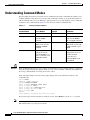
Understanding Command Modes
2-2
Undoing a Command or Feature
2-3
Saving Configuration Changes
Where to Go Next
2-3
2-3
First-Time Configuration
3-1
Understanding Boot Images
3-1
Understanding the Cisco 3825 Router Interface Numbering
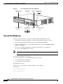
Slot and Port Numbering 3-2
Setup Command Facility 3-3
Before Starting Your Router 3-3
Using the Setup Command Facility
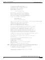
Configuring Global Parameters
Completing the Configuration
3-1
3-4
3-4
3-7
Configuring the Cisco 3825 Mobile Wireless Edge Router in a RAN-O Solution with the
Command-Line Interface 4-1
Before You Begin
4-2
Verifying the Version of Cisco IOS Software
Clocking Requirements for Cisco 3825 Router
Clock-Related Commands 4-3
Show Controller Command
4-2
4-2
4-5
Configuration Sequence 4-6
Configuring the Hostname and Password 4-6
Verifying the Hostname and Password 4-7
Configuring Gigabit Ethernet Interfaces 4-8
Configuring the Backhaul Links 4-9
Extended Availability Drop and Insert (EADI) 4-20
Configuring GSM-Abis Links 4-20
Configuring UMTS Links 4-24
Configuring Redundancy 4-28
Cisco 3825 Mobile Wireless Edge Router Software Configuration Guide
iv
OL-15667-03
Contents
Configuring for SNMP Support 4-33
Configuring Inverse Multiplexing over ATM (IMA) 4-37
Configuring PVC Routing (HSDPA Offload) 4-41
Configuring UMTS QoS 4-46
Configuring UMTS Congestion Management Control 4-55
Configuring Satellite Support 4-58
Configuring Graceful Degradation 4-59
Saving Configuration Changes 4-61
Example Configurations 4-61
Monitoring and Managing the Cisco 3825 Router 4-69
Enabling the Cisco 3825 Router for Remote Network Management
Show Commands for Monitoring the Cisco 3825 Router 4-71
Where to Go Next
4-69
4-73
APPENDIX
A
Cisco 3825 Mobile Wireless Edge Router RAN-O Command Reference
APPENDIX
B
Configuration Examples
A-1
B-1
Overview B-1
Asymmetric PWE3 Configuration B-2
Ethernet over MPLS—VLAN and Port Mode Configuration B-15
PWE3 over MLPPP Configuration B-21
PWE3 Redundancy Configuration B-30
TDM over MPLS Configuration B-36
ATM over MPLS Configurations B-41
ATM over L2TPv3 Configuration B-48
GSM Only Configuration B-55
UMTS Only Configuration without IMA B-59
Combined GSM and UMTS Configuration B-63
GSM and UMTS with IMA Configuration B-68
GSM and UMTS with IMA and PVC Routing (HSDPA Offload) Configuration
GSM Only Configuration via Satellite B-80
GSM Congestion Management B-83
UMTS Congestion Management B-84
B-74
INDEX
Cisco 3825 Mobile Wireless Edge Router Software Configuration Guide
OL-15667-03
v
Contents
Cisco 3825 Mobile Wireless Edge Router Software Configuration Guide
vi
OL-15667-03
Preface
This preface describes the objectives, audience, organization, and conventions of this software
configuration guide.
This preface contains the following sections:
•
Document Revision History, page vii
•
Objectives, page vii
•
Audience, page viii
•
Organization, page viii
•
Conventions, page viii
•
Related Documentation, page ix
•
Obtaining Documentation, Obtaining Support, and Security Guidelines, page x
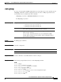
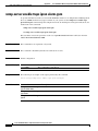
Document Revision History
The Document Revision History table below records technical changes to this document. The table
shows the document revision number for the change, the date of the change, and a brief summary of the
change. Note that not all Cisco documents use a Document Revision History table.
Revision
Date
OL-15667-03 August 14, 2008
Change Summary
Provided the following information for Cisco IOS 12.4(19)MR):
Described use of the ima group-id command, which the user can
employ to configure the IMA Group ID on an IMA interface.
OL-15667-02 April 1, 2008
Introduced the following features with Cisco IOS 12.4(16)MR2:
Keyword ignore-vpi-vci added to the xconnect command for n:1
VCC cell mode PW
OL-15667-01 March 6, 2008
Initial release.
Objectives
This guide explains how to configure features that enable the Cisco 3825 Mobile Wireless Edge Router to
be implemented in an IP Radio Access Network-Optimization (RAN-O) environment.
Cisco 3825 Mobile Wireless Edge Router Software Configuration Guide
OL-15667-03
vii
Preface
Audience
This publication is designed for the person who will be responsible for configuring the router. This guide
is intended for the following audiences:
•
Customers with technical networking background and experience
•
System administrators who are familiar with the fundamentals of router-based internet working, but
who may not be familiar with Cisco IOS software
•
System administrators who are responsible for installing and configuring internetworking
equipment, and who are familiar with Cisco IOS software
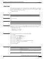
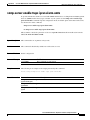
Organization
The major sections of this software configuration guide are listed in the following table:
Chapter
Title
Description
Chapter 1
Overview of the
Cisco 3825 Mobile Wireless
Edge Router
Describes the purpose of the Cisco 3825 router and its
unique software features.
Chapter 2
Cisco IOS Software Basics
Describes what you need to know about the Cisco IOS
software.
Chapter 3
First-Time Configuration
Describes how to use the setup command facility to
configure basic attributes of your router.
Chapter 4
Configuring the
Cisco 3825 Mobile Wireless
Edge Router in a RAN-O
Solution with the
Command-Line Interface
Describes how to use the Cisco IOS software CLI to
configure basic router functionality in a RAN-O
environment.
Appendix A
Cisco 3825 Mobile Wireless
Edge Router RAN-O
Command Reference
Provides information about new and changed
commands.
Appendix B
Configuration Examples
Provides examples of configurations.
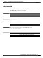
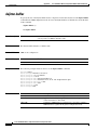
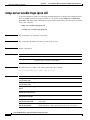
Conventions
This publication uses the following conventions to convey instructions and information.
Convention
Description
boldface font
Commands and keywords.
italic font
Variables for which you supply values.
[
Keywords or arguments that appear within square brackets are optional.
]
{x | y | z}
A choice of required keywords appears in braces separated by vertical bars. You must select one.
screen font
Examples of information displayed on the screen.
boldface screen
Examples of information you must enter.
font
Cisco 3825 Mobile Wireless Edge Router Software Configuration Guide
viii
OL-15667-03
Preface
Convention
Description
<
>
Nonprinting characters, for example passwords, appear in angle brackets.
[
]
Default responses to system prompts appear in square brackets.
Note
Timesaver
Tip
Caution
Means reader take note. Notes contain helpful suggestions or references to material not covered in the
manual.
Means the described action saves time. You can save time by performing the action described in the
paragraph.
Means the following information will help you solve a problem. The tips information might not be
troubleshooting or even an action, but could be useful information, similar to a Timesaver.
Means reader be careful. In this situation, you might do something that could result in equipment
damage or loss of data.
Related Documentation
The following list includes documentation related to your product by implementation.
Cisco Mobile Wireless RAN Optimization
•
Cisco 3825 Mobile Wireless Edge Router Documents
– Cisco 3800 Series Hardware Installation
•
Cisco Interface Cards Installation Guides
– Quick Start Guide: Interface Cards
– Cisco Interface Cards Installation Guide
– Cisco 2-port T1/E1-RAN Installation Instructions
•
Cisco Network Modules Installation Guides
– Network Modules Quick Start Guide
– Cisco Network Modules Hardware Installation Guide
•
Release Notes
– Release Notes for the Cisco 3825 Mobile Wireless Edge Router
Note
To obtain the latest information, access the online documentation.
Cisco 3825 Mobile Wireless Edge Router Software Configuration Guide
OL-15667-03
ix
Preface
Obtaining Documentation, Obtaining Support, and Security
Guidelines
For information on obtaining documentation, obtaining support, providing documentation feedback,
security guidelines, and also recommended aliases and general Cisco documents, see the monthly
What’s New in Cisco Product Documentation, which also lists all new and revised Cisco technical
documentation, at:
http://www.cisco.com/en/US/docs/general/whatsnew/whatsnew.html
Cisco 3825 Mobile Wireless Edge Router Software Configuration Guide
x
OL-15667-03
CH A P T E R
1
Overview of the Cisco 3825 Mobile Wireless
Edge Router
The Cisco 3825 Mobile Wireless Edge Router is a networking platform optimized for use in mobile
wireless networks; specifically designed to be used at the cell site edge as a part of a 2G, 3G or 4G Radio
Access Network (RAN). The Cisco 3825 Mobile Wireless Edge Router is a general purpose router
platform specializing in 2/2.5G Global System for Mobile Communication (GSM) and 3G Universal
Mobile Telecommunication System (UMTS) RAN backhaul transport and optimization.
The Cisco 3825 router offers high performance at a low cost while meeting the critical requirements for
deployment in cell sites, including small size, high availability, and
DC input power flexibility.
This chapter includes the following sections:
•
Introduction, page 1-1
•
Cisco IOS Software Features, page 1-6
•
MIB Support, page 1-10
•
Limitations and Restrictions, page 1-11
•
New Features in Cisco IOS Release 12.4(16)MR2, page 1-13
•
New Features in Cisco IOS Release 12.4(16)MR1, page 1-13
•
New Features in Cisco IOS Release 12.4(16)MR, page 1-27
Introduction
A typical RAN is composed of thousands of Base Transceiver Stations (BTSs)/Node Bs, hundreds of
Base Station Controllers/Radio Network Controllers (BSCs/RNCs), and several Mobile Switching
Centers (MSCs). The BTSs/Node Bs and BSCs/RNCs are often separated by large geographic distances,
with the BTSs/Node Bs located in cell sites uniformly distributed throughout a region, and the BSCs,
RNCs, and MSCs located at suitably chosen central offices (COs) and/or Mobile Telephone Switching
Offices (MTSOs). The traffic generated by a BTS/Node B is transported to the corresponding BSC/RNC
across a network, referred to as the backhaul network, which is often a hub-and-spoke topology with
hundreds of BTSs/Node Bs connected to a given BSC/RNC by point-to-point time-division multiplexing
(TDM) trunks. These TDM trunks may be leased line T1/E1s or their logical equivalents, such as
microwave links or satellite channels. The interface between the BTS and BSC in GSM and Code
Cisco 3825 Mobile Wireless Edge Router Software Configuration Guide
OL-15667-03
1-1
Chapter 1
Overview of the Cisco 3825 Mobile Wireless Edge Router
Introduction
Division Multiple Access (CDMA) systems is called the Abis interface. The interface between the Node
B and RNC in a UMTS system is called the Iub interface (see Appendix B, “Configuration Examples”,
for sample configurations.
RAN-Optimization Implementation
In RAN-Optimization (RAN-O), the Cisco 3825 router extends IP connectivity to the cell site and BTS.
The router provides bandwidth-efficient IP transport of GSM and UMTS voice and data bearer traffic,
as well as maintenance, control, and signaling traffic, over the leased line backhaul network between the
BTS and leased line termination and aggregation node via compression (cRTP/cUDP) and packet
multiplexing (Multilink PPP).
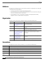
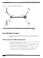
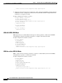
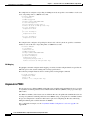
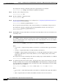
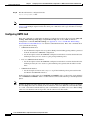
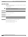
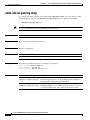
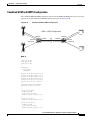
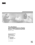
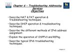
Figure 1-1 shows an example of the placement of and connections for the Cisco 3825 router in RAN-O.
Figure 1-1
Example of Cisco 3825 Router in a RAN-O
Active
T1/E1
T1/E1 backhaul link to
IP RAN aggregation node
Standby
Cisco MWR pair
203231
GSM
BTS or
UMTS
Node-B
The BTS site consists of a pair of Cisco 3825 routers. The pair of routers provides an active router and
a standby router for redundancy. A failure of the active router causes the standby router to take over as
the active router for the BTS site.
Each pair of Cisco 3825 routers at the BTS site is identical in hardware configuration. The two routers
connect to each other through the Gigabit Ethernet (GE) interfaces. The individual backhaul links to a
Cisco 3825 router are cabled from a single T1/E1 termination block in the BTS, connecting to both the
active and standby routers by means of a Y cable. The redundancy design to control the active/standby
transitions of the router pair leverages Hot Standby Router Protocol (HSRP) to control the relays on the
Cisco 2-port T1/E1-RAN interface card, Cisco product number VWIC-2T1/E1-RAN (for more
information, see Cisco 2-port T1/E1-RAN Installation Instructions) in each router to ensure that the relays
on the active router are closed while the relays on the standby router are open, thus avoiding double
termination of the T1 (or E1).
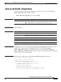
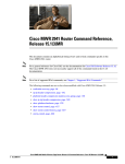
Cisco Abis and Iub Optimization over IP Implementation
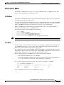
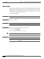
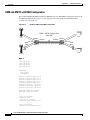
One solution that mobile wireless operators find of value is Cisco’s ability to optimize RAN backhaul
efficiency (see Figure 1-2). For example, Cisco’s GSM Abis Optimization solution increases the T1/E1
bandwidth efficiency by as much as 50%. This means the current traffic loads can be carried using half
as many T1/E1 trunks as are presently used. This allows more voice and data calls to be carried over the
existing RAN backhaul network, eliminating the need for the operator to add expensive new T1/E1
trunks as traffic demands grow. It will also allow a number of existing trunks to be decommissioned,
putting an end to their recurring costs.
Cisco 3825 Mobile Wireless Edge Router Software Configuration Guide
1-2
OL-15667-03
Chapter 1
Overview of the Cisco 3825 Mobile Wireless Edge Router
Introduction
Another equally important benefit is that substantial excess capacity is now available in the existing
RAN backhaul network. The operator can reallocate this recovered bandwidth to carry traffic from other
radios, such as UMTS Node Bs, GPRS, EDGE, 1xEV-DO, PWLANs, and other data overlays. This
capability reduces the deployment and operating costs for new technologies, since the operator avoids
the up-front and recurring costs of supplementing backhaul capacity. It also accelerates time to revenue
from deployments of new radio technologies since there is no need for the operator to wait for additional
microwave licenses or leased lines to be supplied.
Compliance with 3GPP2 and 3GPP R5 and R6 transport standards is another appealing aspect of Cisco’s
RAN-O solution. Cisco converts today’s CDMA transport networks into 3GPP2-compliant IP RAN
transport networks, and GSM and R4/R99 UMTS transport networks into R5/R6 IP RAN transport
networks now—and adds multi-radio backhaul compression as well. This means operators can enjoy the
benefits of IP transport in their CDMA, GSM, and R4/R99 UMTS RANs today.
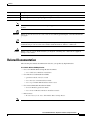
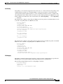
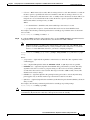
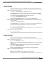
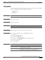
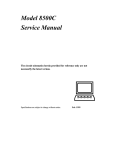
Figure 1-2
Example of Cisco 3825 Router in a GSM Abis and UMTS Iub Optimization over IP
GSM BTS
IP-PBX
BSC
TDM
TDM
Cisco
ONS 15454
Cisco
MWR
T1/E1
100Base-T
IP-PBX
Optimized Abis/lub over IP
PWLAN
WCDMA-TDD
WiMAX
(802.16/20)
IP
UMTS Node B
(R4/R99)
HSDPA
UMTS Node B
(RS/R6)
Cell Site
Mobile IP/FA
VoIP
Content Caching
Multi VPN
IP Multicasting
QoS
PPP
DHCP
Routing
Access Network
IP
Cisco
Mobile
Exchange
RNC
203232
ATM
ATM
BSC/RNC Site
Mobile
Internet
Edge
Cisco GSM Abis Optimization over IP
The Cisco GSM Abis Optimization over IP technology improves T1/E1 bandwidth efficiency by 33% to
50%, corresponding to a GSM voice call capacity gain of 50-100% per T1/E1, depending on the nature
of the traffic on the interface.
In a GSM RAN, the interface between the BTS and BSC is a 3GPP reference interface called the Abis
interface. The physical trunk connecting a BTS and BSC is typically a T1 or E1 circuit, and carries 24
(T1) or 32 (E1) separate 64 kbps DS0 channels. One or two of these DS0 channels is used to carry control
and signaling traffic, while the remainder are used to carry bearer traffic—voice and data from mobile
Cisco 3825 Mobile Wireless Edge Router Software Configuration Guide
OL-15667-03
1-3
Chapter 1
Overview of the Cisco 3825 Mobile Wireless Edge Router
Introduction
users. Each DS0 bearer channel carries up to four sub-multiplexed 16 kbps channels, termed sub-rate
DS0s. The voice and data bearer traffic is carried over the sub-rate DS0s in Transcoder and Rate Adaptor
Unit (TRAU) frames in accordance with 3GPP TS 08.60 v8.2.1, “In-band control of transcoders and rate
adaptors for Enhanced Full Rate (EFR) and full rate traffic channels.” There are several types of TRAU
frames: full-rate (FR) or enhanced full-rate (EFR) GSM vocoder frames; Adaptive Multi-Rate (AMR)
vocoder frames; silent speech frames; and OAM frames. When a sub-rate DS0 is assigned to a call,
TRAU frames are generated in accordance with 3GPP TS 08.60 v8.2.1, “In-band control of transcoders and
rate adaptors for EFR and full rate traffic channels.” When a sub-rate DS0 is idle, that is, not assigned to a
call, a repeating idle pattern is transmitted in accordance with 3GPP TS 08.54 v8.0.1, “Base Station
Controller-Base Transceiver Station (BSC-BTS) interface; Layer 1 structure of physical circuits.”
The transcoder and rate adaptation control function that specifies the TRAU frames provides several
opportunities to optimize the Abis interface, and thus optimize the backhaul bandwidth efficiency. For
example, when Discontinuous Transmission (DTX) is employed over the air interface, the TRAU frames
that are transported on the Abis interface contain standardized redundant bit patterns, known as idle
(silent) speech frames (FR and EFR) or “no data” frames (AMR), whenever a voice user is silent
(typically 40-60% of the time). As another example, bearer channels that are not assigned to calls each
carry known idle bit patterns on the Abis interface as mentioned previously. Thus, even though no radio
transmissions are made during silent and idle periods, redundant information is nevertheless transported
across the backhaul network thereby unnecessarily consuming precious bandwidth.
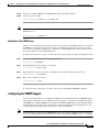
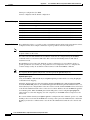
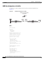
Cisco Pseudowire Emulation Edge-to-Edge (PWE3)
PWE3 is a mechanism that emulates the essential attributes of a service, such as ATM or EI/T1 (see
Figure 1-3). The required functions of pseudowires (PWs) include encapsulating service-specific Packet
Data Units (PDUs) arriving at an ingress port and carrying them across a path or tunnel, managing their
timing and order, and any other operations required to emulate the behavior and characteristics of the
service as efficiently as possible.
PW is perceived as an unshared link or circuit of the chosen service. However, there may be deficiencies
that impede some applications from being carried on a PW. These limitations should be fully described
in the appropriate service-specific documents and applicability statements.
Cisco supports standards-based PWE3 as defined by:
•
Structure-agnostic TDM over Packet (SAToP), page 1-16
•
Structure-aware TDM CESoPSN, page 1-16
•
Transportation of ATM Service via MPLS/IP (PWE3/ATM), page 1-17
•
Transportation of ATM Service via L2TPv3, page 1-20
A PW is a connection between two provider edge (PE) devices, which connects two attachment circuits
(ACs). An AC can be an ATM virtual path identifier/virtual channel identifier (VPI/VCI) or an T1/E1
link.
Cisco 3825 Mobile Wireless Edge Router Software Configuration Guide
1-4
OL-15667-03
Chapter 1
Overview of the Cisco 3825 Mobile Wireless Edge Router
Introduction
Figure 1-3
ATM/TDM
Example of Cisco 3825 Router in a PWE3f
xconnect
xconnect
ATM/TDM
MPLS/IP or L2TPv3
Emulated Circuit
201865
Pseudowire
Cisco Iub Optimization over IP
The Cisco Iub Optimization over IP technology for R4/R99 (ATM) UMTS RANs improves bandwidth
efficiency by as much as 15 to 40%, corresponding to a UMTS voice call capacity gain of 18 to 67%,
depending on the type of Iub header and ATM Adaptation Layer traffic sub-cell multiplexing
performance. For R5/R6 IP UMTS RANs, Cisco provides compression and low-overhead encryption.
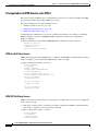
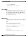
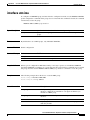
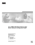
Intelligent Cell Site IP Services
Cisco’s RAN-O solutions also open up the possibility to deliver new profit-enhancing services. This is
achieved through the rich set of IP networking features supported in Cisco IOS Software that are now
extended to the cell site (see Figure 1-4 on page 1-6).
Cell Site Points-of-Presence (POPs)
Since many cell sites are located in and around downtown areas, hotels, airports, and convention centers,
they make attractive sites for co-locating public wireless LAN (PWLAN) access points and other
wireless data overlays. Many of these wireless data radios are IP-based. IP networking features, like
Mobile IP, VoIP, IP Multicast, Virtual Private Network (VPN), and content caching, enable delivery of
new revenue-generating services over these radios. Cisco also provides a wide range of low-latency
IP-based quality of service (QoS) and traffic shaping models to allow flexible mixing of multiple traffic
types across the same backhaul network. Thus, the cell site becomes a physical point of presence or POP
from which to offer hotspot services, or voice and wired Internet service provider (ISP) services to
nearby enterprises and residences. The corresponding traffic “rides for free” on the spare backhaul
bandwidth made available by Cisco’s Abis and Iub Optimization solutions.
Cisco 3825 Mobile Wireless Edge Router Software Configuration Guide
OL-15667-03
1-5
Chapter 1
Overview of the Cisco 3825 Mobile Wireless Edge Router
Cisco IOS Software Features
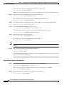
Figure 1-4
Example of Cisco 3825 Router in a Cell Site POP
GSM/GPRS/
EDGE BTS
BSC
TDM
TDM
Cisco
MWR
Cisco
ONS 15454
T1/E1
Optimized Abis and lub over IP
ATM
ATM
(AAL2/AAL5)
UMTS Node B
(R4/R99)
203233
RNC
Cell Site
Access Network
BSC/RNC Site
Mobile
Internet
Edge
Cisco IOS Software Features
There is one version of software available for the Cisco 3825 router. This version of the software is
required for implementing the Cisco 3825 router in a Radio Access Network-Optimization (RAN-O)
configuration.
Software features for the RAN-O Implementation
The software required for implementing the Cisco 3825 router consists the Cisco IOS software running
on the MIPs-based portion of the Cisco 3825 router hardware.
Cisco IOS software functions added to the Cisco 3825 router for the RAN-O implementation include:
•
Redundancy logic—For monitoring Hot Standby Router Protocol (HSRP) information to determine
the active and standby router and control T1 termination.
•
Failover logic—To force a switchover for hardware failures or an over-temperature condition.
•
Relay control—To open and close the T1/E1 interfaces on the active and standby routers.
•
Diagnostic functions—To monitor the “health” of the standby Cisco 3825 router.
Cisco 3825 Mobile Wireless Edge Router Software Configuration Guide
1-6
OL-15667-03
Chapter 1
Overview of the Cisco 3825 Mobile Wireless Edge Router
Cisco IOS Software Features
Software Features
Standard Cisco IOS software features supported in the Cisco 3825 router for the RAN-O
implementation include:
Simple Services
•
DHCP
•
PPP
•
NAT
•
OSPF
•
RIP
Intelligent Services
•
QoS
•
VPN
•
IP Multicast
•
Mobile IP/FA
•
content caching
•
MPLS
•
L2TPv3
Other Services
•
ACFC and PFC Handling During PPP Negotiation
•
HSRP
•
NTP
•
SNMP
Redundancy Support
In a RAN-O application, to ensure availability, the backhaul links to a Cisco 3825 router are redundantly
cabled to the Cisco 2-port T1/E1-RAN card. This card, designed specifically for the
Cisco MWR 1941-DC-A router and Cisco 3825 router includes relays that activate the T1/E1 ports.
These relays allow “Y” cabling for router redundancy where the T1/E1 link is not redundant and default
to open. The relays are controlled by HSRP/redundancy protocol between the two routers connected to
the same T1/E1.
Note
If you choose to use the Cisco 3825 router in a non-redundant configuration, you must close the relays
on the card using the standalone subcommand. Also, redundancy parameters are processed when the
router is booted up. These parameters cannot be changed “on the fly.”
HSRP
Cisco’s HSRP is used to control which router is active and which is standby. HSRP uses a priority
scheme to determine which HSRP-configured router is to be the default active router. Priority is
determined first by the configured priority value, then by the IP address. In each case, a higher value is
of greater priority.
Cisco 3825 Mobile Wireless Edge Router Software Configuration Guide
OL-15667-03
1-7
Chapter 1
Overview of the Cisco 3825 Mobile Wireless Edge Router
Cisco IOS Software Features
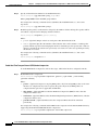
Configuration Statements for CISCO-IP-RAN-BACKHAUL-MIB
This section contains detailed information on how to enable notifications provided by the
CISCO-IP-RAN-BACKHAUL-MIB.
With Cisco IOS Release 12.4(16)MR1, the Cisco 3825 router supports the following MIB:
CISCO-IP-RAN-BACKHAUL-MIB
This MIB is compatible with Cisco Mobile Wireless Transport Manager (MWTM) 5.0 or later. It
provides information on the optimization on the optimization of the following traffic types:
•
GSM—providing information between a BTS and the corresponding BSC
•
UMTS—providing information on optimization between a Node Band the corresponding RNC.
NOTIFICATIONS
ciscoIpRanBackHaulGsmAlarm
Provides information alarms associated with Global System for Mobile Communications (GSM)-Abis
interfaces. Only enables GSM Abis. See Appendix A, “Cisco 3825 Mobile Wireless Edge Router
RAN-O Command Reference” for more information.
conf t
snmp-server enable traps ipran alarm-gsm
ciscoIpRanBackHaulUmtsAlarm
Provides information alarms associated with Universal Mobile Telecommunications System
(UMTS)-Iub interfaces. Only enables UMTS Iub. See Appendix A, “Cisco 3825 Mobile Wireless Edge
Router RAN-O Command Reference” for more information.
conf t
snmp-server enable traps ipran alarm-umts
ciscoIpRanBackHaulRcvdUtil + ciscoIpRanBackHaulSentUtil
Provides information on backhaul utilization. Only enables backhaul utilization. See Appendix A,
“Cisco 3825 Mobile Wireless Edge Router RAN-O Command Reference” for more information.
conf t
snmp-server enable traps ipran util
Note
The snmp-server enable traps ipran util command is obsolete. CLI accepts the command to maintain
compatibility.
To specify all notifications, specify the component name. See Appendix A, “Cisco 3825 Mobile
Wireless Edge Router RAN-O Command Reference” for more information.
conf t
snmp-server enable traps ipran
The following configuration statements are used to provide additional information about device and
control generation of notifications:
ipran-mib ?
backhaul-notify-interval
Interval for backhaul utilization (Obsolete.
Provided only to maintain compatibility.)
location
Location of device
snmp-access
Specify type snmp connectivity
Cisco 3825 Mobile Wireless Edge Router Software Configuration Guide
1-8
OL-15667-03
Chapter 1
Overview of the Cisco 3825 Mobile Wireless Edge Router
Cisco IOS Software Features
ipran-mib ?
threshold-acceptable
Acceptable utilization threshold (Obsolete.
Provided only to maintain compatibility.)
threshold-overloaded
Overloaded utilization threshold (Obsolete.
Provided only to maintain compatibility.)
threshold-warning
Warning utilization threshold (Obsolete. Provided
only to maintain compatibility.)
ipran-mib backhaul-notify-interval
For more information on these commands, see Appendix A, “Cisco 3825 Mobile Wireless Edge Router
RAN-O Command Reference”.
Cisco 3825 Mobile Wireless Edge Router Software Configuration Guide
OL-15667-03
1-9
Chapter 1
Overview of the Cisco 3825 Mobile Wireless Edge Router
MIB Support
MIB Support
The Cisco 3825 router supports the following MIBs:
•
ADSL-DMT-LINE-MIB
•
CISCO-IETF-ATM2-PVCTRAP-MIB-EXTN
•
ADSL-LINE MIB
•
CISCO-IETF-ATM2-PVCTRAP-MIB
•
ATM-MIB
•
CISCO-IETF-NAT-MIB
•
BRIDGE-MIB
•
CISCO-IETF-PW-MIB
•
CISCO-AAA-SERVER-MIB
•
CISCO-IETF-PW-MPLS-MIB
•
CISCO-AAL5-MIB
•
CISCO-IETF-PW-TC-MIB
•
CISCO-ACCESS-ENVMON-MIB
•
CISCO-IF-EXTENSION-MIB
•
CISCO-ATM-EXT-MIB
•
CISCO-IMAGE-MIB
•
CISCO-ATM-PVCTRAP-EXTN-MIB
•
CISCO-IP-RAN-BACKHAUL-MIB
•
CISCO-BULK-FILE-MIB
•
CISCO-IPMROUTE-MIB
•
CISCO-CALL-APPLICATION-MIB
•
CISCO-MEMORY-POOL-MIB
•
CISCO-CALL-HISTORY-MIB
•
CISCO-MVPN-MIB
•
CISCO-CAR-MIB
•
CISCO-NBAR-PROTOCOL-DISCOVERY-MIB
•
CISCO-CAS-IF-MIB
•
CISCO-NETFLOW-MIB
•
CISCO-CCME-MIB
•
CISCO-NTP-MIB
•
CISCO-CDP-MIB
•
CISCO-PIM-MIB
•
CISCO-CIRECUIT-INTERFACE-MIB
•
CISCO-PING-MIB
•
CISCO-CLASS-BASED-QOS-MIB
•
CISCO-POP-MGMT-MIB
•
CISCO-CONFIG-MAN-MIB
•
CISCO-PPPOE-MIB
•
CISCO-DIAL-CONTROL-MIB
•
CISCO-PROCESS-MIB
•
CISCO-DSL-CPE-MIB
•
CISCO-QUEUE-MIB
•
CISCO-ENTITY-ASSET-MIB
•
CISCO-RTTMON-MIB
•
CISCO-ENTITY-EXT-MIB
•
CISCO-SAA-APM-MIB
•
CISCO-ENTITY-VENDORTYPE-OLD-MIB
•
CISCO-SMI
•
CISCO-ENVMON-MIB
•
CISCO-SNAPSHOT-MIB
•
CISCO-FLASH-MIB
•
CISCO-SNMP--TARGET-EXT-MIB
•
CISCO-FRAME-RELAY-MIB
•
CISCO-SRST-MIB
•
CISCO-FTP-CLIENT-MIB
•
CISCO-STACKMAKER-MIB
•
CISCO-HSRP-MIB
•
CISCO-SYSLOG-MIB
•
CISCO-ICSUDSU-MIB
•
CISCO-TC
Cisco 3825 Mobile Wireless Edge Router Software Configuration Guide
1-10
OL-15667-03
Chapter 1
Overview of the Cisco 3825 Mobile Wireless Edge Router
Limitations and Restrictions
•
CISCO-TCP-MIB
•
IP-FORWARD-MIB
•
CISCO-VLAN-IFTABLE-RELATIONSHIPMIB
•
ISDN-MIB
•
MSDP-MIB
•
CISCO-VLAN-MEMBERSHIP-MIB
•
OLD-CISCO-CHASSIS-MIB
•
CISCO-VOICE-ANALOG-IF-MIB
•
OLD-CISCO-FLASH-MIB
•
CISCO-VOICE-ATM-DIAL-CONTROL-MIB
•
OLD-CISCO-INTERFACES-MIB
•
CISCO-VOICE-COMMON-DIAL-CONTROLMIB
•
OLD-CISCO-IP-MIB
•
CISCO-VOICE-DIAL-CONTROL-MIB
•
OLD-CISCO-SYS-MIB
•
CISCO-VOICE-DNIS-MIB
•
OLD-CISCO-TCP-MIB
•
CISCO-VOICE-ENABLED-LINK-MIB
•
OLD-CISCO-TS-MIB
•
CISCO-VOICE-FR-DIAL-CONTROL-MIB
•
OSPF-MIB
•
CISCO-VOICE-IF-MIB
•
OSPF-TRAP-MIB
•
CISCO-VOICE-NUMBER-EXPANSION-MIB
•
PIM-MIB
•
CISCO-VOICE-URI-CLASS-MIB
•
RFC1213-MIB
•
CISCO-VPDN-MGMT-EXT-MIB
•
RFC1231-MIB
•
CISCO-VPDN-MGMT-MIB
•
RFC1315-MIB
•
CISCO-VTP-MIB
•
RFC1406-MIB
•
DIAL-CONTROL-MIB
•
RMON-MIB
•
DS1-MIB
•
RS-232-MIB
•
DS3-MIB
•
RSVP-MIB
•
ETHERLIKE-MIB
•
SMON-MIB
•
EVENT-MIB
•
SNMP-TARGET-MIB
•
EXPRESSION-MIB
•
SONET-MIB
•
IF-MIB
•
TCP-MIB
•
IGMP-MIB
•
UDP-MIB
•
IMA-MIB
•
VRRP-MIB
•
INT-SERV-GUARANTEED-MIB
•
XGCP-MIB
•
INT-SERV-MIB
Limitations and Restrictions
The following restrictions applies when using the Cisco 2-port T1/E1-RAN interface card in the
Cisco 3825 router:
Caution
The Cisco 3825 router does not support online insertion and removal (OIR) of the
Cisco 2-port T1/E1-RAN interface card. Any attempt to perform OIR on a card in a powered up router
might cause damage to the card.
Cisco 3825 Mobile Wireless Edge Router Software Configuration Guide
OL-15667-03
1-11
Chapter 1
Overview of the Cisco 3825 Mobile Wireless Edge Router
Limitations and Restrictions
Caution
The Cisco 3825 router does not support OIR of network modules. Any attempt to perform OIR on a card
in a powered up router might cause damage to the card.
Note
The Cisco NM-2W network interface module only is only supported on the Cisco 3825 router on
shorthaul with or without Inverse Multiplexing over ATM (IMA). It is not supported on the Cisco 3825
router on shorthaul with GSM.
RAN-O Implementation Limitations and Restrictions
The following list of restrictions applies when implementing the Cisco 3825 router in a Radio Access
Network-Optimization (RAN-O) configuration.
Hardware not Supported on the Cisco 3825 Router
Use of additional voice/WAN interface card (VWIC) cards. The only supported VWIC is the Cisco
2-port T1/E1-RAN.
UMTS Iub and GSM Abis Implementation Limitations and Restrictions
The following list of restrictions applies when implementing the UMTS Iub or GSM Abis application in
a RAN-O configuration.
Hardware not Supported for UMTS Iub
The Cisco MWR 1941-DC router does not support UMTS Iub as it does not include the Advanced
Integration Module (AIM) slot connector on the motherboard. Only the Cisco MWR 1941-DC-A router
and Cisco 3825 router are supported for UMTS Iub.
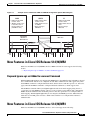
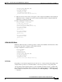
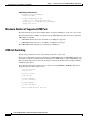
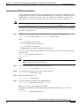
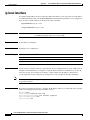
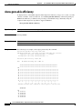
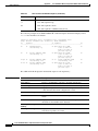
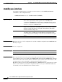
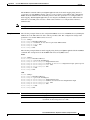
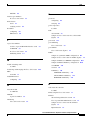
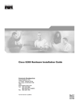
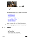
Hardware not Supported for GSM Abis
The Network Interface Module (NM-2W) does not support GSM Abis as the HDLC Controller channel
does not interface with the NM-2W. GSM Abis is only supported through the Cisco 2-port T1/E1-RAN
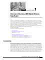
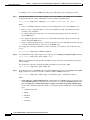
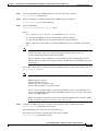
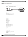
card through the four voice/WAN interface card (VWIC) ports on the Cisco 3825 router (see Figure 1-5
on page 1-13).
Cisco 3825 Mobile Wireless Edge Router Software Configuration Guide
1-12
OL-15667-03
Chapter 1
Overview of the Cisco 3825 Mobile Wireless Edge Router
New Features in Cisco IOS Release 12.4(16)MR2
Example of Cisco 3825 Router VWIC and NM-2W Configuration Options Block Diagram
GSM
UMTS
IP
• VWIC-2T1/E1-RAN
used for T1/E1
• *MUST* reside in one
of four WIC slots to
traverse HDLC Ctrl
(8 GSM E1 max)
• VWIC-2T1/E1-RAN
used for T1/E1
• VWIC FPGA unused
for UMTS
• Direct routing to
AIM-ATM
• VWIC-2T1/E1-RAN
used for T1/E1
• VWIC FPGA unused
for IP
• Direct routing to
IOS CPU
AIM-ATM-8
Module on
Motherboard
NM - 2W
HDLC Ctrl
NM - 2W
RAN WIC RAN WIC
UMTS
lub
IOS CPU
RAN WIC RAN WIC
IP UMTS
lub
IP
RAN WIC RAN WIC RAN WIC RAN WIC
UMTS
lub
UMTS
lub
IP
280206
Figure 1-5
GSM
Abis
New Features in Cisco IOS Release 12.4(16)MR2
With Cisco IOS Release 12.4(16)MR2, the Cisco MWR 1941-DC-A router supports the following
feature:
•
Keyword ignore-vpi-vci Added to xconnect Command, page 1-13
Keyword ignore-vpi-vci Added to xconnect Command
With the ignore-vpi-vci keyword configured, the MWR ignores the VPI/VCI value in the PW packet and
does a blind rewrite with the local configured AC-side PVC's VPI/VCI value. This applies only when
the xconnect command is configured under the PVC, which is the N:1 with N=1 special case. It does not
apply when the xconnect command is configured under the subinterface, which supports N>1.
The xconnect command with keyword ignore-vpi-vci results in the PVC mapping being done in a
cooperative way if the MWR works the same way as the receiving router. Without this command, the
MWR checks the VPI/VCI value inside PW packet for matches against the local configured PVC or
PVC-mapping. With the ignore-vpi-vci keyword configured, the MWR ignores the VPI/VCI header
inside the received PW packet and does a blind rewrite with the local configured AC-side PVC's
VPI/VCI value.
New Features in Cisco IOS Release 12.4(16)MR1
With Cisco IOS Release 12.4(16)MR1, the Cisco 3825 router supports the following:
Cisco 3825 Mobile Wireless Edge Router Software Configuration Guide
OL-15667-03
1-13
Chapter 1
Overview of the Cisco 3825 Mobile Wireless Edge Router
New Features in Cisco IOS Release 12.4(16)MR1
•
Emulation of TDM Circuit via MPLS/IP (PWE3/TDM), page 1-14
– Structure-agnostic TDM over Packet (SAToP), page 1-16
– Structure-aware TDM CESoPSN, page 1-16
•
Transportation of ATM Service via MPLS/IP (PWE3/ATM), page 1-17
– Transparent Cell Transport Service/ATM Port Mode, page 1-17
– ATM N-to-One VCC Cell Mode, page 1-17
– ATM AAL5 CPCS-SDU Mode, page 1-18
– ATM One-to-One VCC Cell Mode, page 1-18
•
Transportation of ATM Service via L2TPv3, page 1-20
– ATM Port Cell Relay Service, page 1-20
– ATM VCC Cell Relay Service, page 1-20
– ATM AAL5-SDU Mode, page 1-21
•
Asymmetric PWE3, page 1-22
•
Ethernet over MPLS, page 1-23
– VLAN Mode, page 1-23
– Port Mode, page 1-23
•
PWE3 over MLPPP, page 1-24
•
PWE3 Redundancy, page 1-24
– TDM PWE3 Redundancy, page 1-25
– ATM PWE3 Redundancy, page 1-25
– Ethernet PWE3 Redundancy, page 1-25
•
Maximum Number of Supported ATM Ports, page 1-26
•
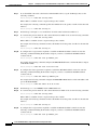
ATM Cell Switching, page 1-26
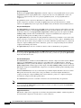
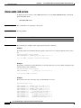
Emulation of TDM Circuit via MPLS/IP (PWE3/TDM)
PWE3 is a mechanism that emulates the essential attributes of a T1/E1 line over a packet-switched
network (PSN). This evolutionary technology allows you to migrate all packet networks from legacy
TDM networks, yet provides transport for legacy applications. PWE3/TDM emulates T1/E1
unstructured and structured lines, including NxDS0 circuits over a Multiprotocol Label Switching
(MPLS) infrastructure.
Configuration for provisioning and creating the PW is done through the existing xconnect interface.
A new command cem-group has been added to this feature to create a circuit emulation (CEM) channel
from one or more time slots of T1/E1.
The group-number keyword identifies the group number used for this channel.
•
For T1 controller, the range is 0-23. (24 cem-groups id)
•
For E1 controller, the range is 0-30. (30 cem-groups id)
Use the unframed keyword to specify that a single CEM channel is being created, including all time slots
with no framing structure defined. If time slots are defined, the PWE3 circuit is circuit emulation service
over packet-switched network (CESoPSN).
Cisco 3825 Mobile Wireless Edge Router Software Configuration Guide
1-14
OL-15667-03
Chapter 1
Overview of the Cisco 3825 Mobile Wireless Edge Router
New Features in Cisco IOS Release 12.4(16)MR1
Use the time slots keyword and the timeslot-range argument to specify the time slots to be included in
the CEM channel. The list of time slots may include commas and hyphens with no spaces between the
numbers, commas, and hyphens.
The following example illustrates the use of the cem-group command:
SATOP
controller el 0/0/0
cem-group 0 unframed
int cem 0/0/0
cem 0
xconnect 10.10.10.10 200 encap mpls
CESoPSN
controller e1 0/0/1
cem-group 0 timeslots 1-31
int cem 0/0/1
cem 0
xconnect 10.10.10.10 200 encap mpls
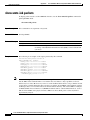
A new command sample-rate has been added to this feature to specify in milliseconds the rate that
hardware samples data on the attached circuit.
The default is 1 ms. The sample-rate command translates into the payload-size that is sent over the
circuit.
•
32-time slots at 1 ms = 256-bytes (32-time slots * 8-bytes/timeslot/ms)
•
24-time slots at 2 ms = 384-bytes (24-time slots * 16-bytes/timeslot/ms)
•
10-time slots at 1 ms = 80-bytes (10-time slots * 8-bytes/timeslot/ms)
The following example illustrates the use of the sample-rate command:
interface CEM0/0/0
no ip address
cem 0
sample-rate 2
xconnect 10.10.10.10 200 encapsulation mpls
A new command dejitter-buffer has been added to this feature to specify the size of the dejitter-buffer
used to compensate for the network jitter.
•
Use the size argument to specify the size of the buffer in milliseconds.
•
Size can vary from 4 - 500 ms; default is 4 ms.
The following example illustrates the use of the dejitter-buffer command:
interface CEM0/0/0
no ip address
cem 0
dejitter-buffer 10
xconnect 10.10.10.10 200 encapsulation mpls
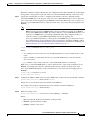
A new command idle-pattern has been added to this feature to specify the data pattern transmitted on
the T1/E1 when missing packets are detected on the PWE3 circuit.
The default idle-pattern command is 0xFF.
Cisco 3825 Mobile Wireless Edge Router Software Configuration Guide
OL-15667-03
1-15
Chapter 1
Overview of the Cisco 3825 Mobile Wireless Edge Router
New Features in Cisco IOS Release 12.4(16)MR1
The following example illustrates the use of the idle-pattern command:
interface CEM0/0/0
no ip address
cem 0
idle-pattern 0x55
xconnect 10.10.10.10 200 encapsulation mpls
A new command shutdown has been added to this feature to administratively shut down the CEM
channel.
Default: cem channel is created in a “no shut” state.
The following example illustrates the use of the shutdown command:
interface CEM0/0/0
no ip address
cem 0
shutdown
xconnect 10.10.10.10 200 encapsulation mpls
A new command class cem has been added to this feature to allow CEM interface parameters to be
configured in a class and applied to CEM interfaces together. This command works in the same manner
for CEM interfaces as the pseudowire-class command does for xconnect.
The following example illustrates the use of the class cem command:
class cem mycemclass
dejitter-buffer 10
sample-rate 2
interface CEM0/0/0
no ip address
cem 0
xconnect 10.10.10.10 200 encapsulation mpls
cem class mycemclass
Structure-agnostic TDM over Packet (SAToP)
SAToP encapsulates TDM bit-streams (T1, E1, T3, E3) as PWs over PSNs. It disregards any structure
that may be imposed on streams, in particular the structure imposed by the standard TDM framing.
The protocol used for emulation of these services does not depend on the method in which attachment
circuits are delivered to the PEs. For example, a T1 attachment circuit is treated in the same way
regardless of whether it is delivered to the PE on copper, multiplexed in a T3 circuit, mapped into a
virtual tributary of a SONET/SDH circuit, or carried over an ATM network using unstructured ATM
circuit emulation service (CES) [ATM-CES]. Termination of any specific “carrier layers” used between
the PE and CEM is performed by an appropriate network service provider (NSP).
Structure-aware TDM CESoPSN
CESoPSN encapsulates structured (NxDS0) TDM signals as PWs over PSNs. It complements similar
work for structure-agnostic emulation of TDM bit-streams, such as PWE3-SAToP.
Emulation of NxDS0 circuits saves PSN bandwidth and supports DS0-level grooming and distributed
cross-connect applications. It also enhances resilience of CE devices to the effects of loss of packets in
the PSN.
Cisco 3825 Mobile Wireless Edge Router Software Configuration Guide
1-16
OL-15667-03
Chapter 1
Overview of the Cisco 3825 Mobile Wireless Edge Router
New Features in Cisco IOS Release 12.4(16)MR1
Transportation of ATM Service via MPLS/IP (PWE3/ATM)
An ATM PW is used to carry ATM cells over an MPLS network. It is an evolutionary technology that
allows you to migrate all packet networks from legacy ATM networks, yet provides transport for legacy
applications.
Configuration for provisioning and creating the PW is done through the existing xconnect command.
The following PW modes are supported in this release:
•
Transparent Cell Transport Service/ATM Port Mode, page 1-17
•
ATM N-to-One VCC Cell Mode, page 1-17
•
ATM AAL5 CPCS-SDU Mode, page 1-18
•
ATM VCC Cell Relay Service, page 1-20
The following examples illustrates how different modes of PWs are configured.
Transparent Cell Transport Service/ATM Port Mode
ATM port mode maps the entire ATM interface to a PW. Use the xconnnect command under the interface
mode to configure a port mode PW.
A sample configuration is written as follows:
interface ATM0/0/0
no ip address
scrambling-payload
atm mcpt-timers 1000 2000 3000
no atm ilmi-keepalive
atm cell-packing 28 mcpt-timer 3
xconnect 99.99.99.99 100 encapsulation mpls sequencing both
pvc 1/35 l2transport
encapsulation aal0
!
pvc 1/36 l2transport
encapsulation aal0
!
pvc 1/37 l2transport
encapsulation aal0
!
ATM N-to-One VCC Cell Mode
ATM N:1 VCC cell relay mode maps one or more permanent virtual circuits (PVCs) to one PW. There
are two ways to configure N:1 VCC in cell relay mode:
1.
When only one PVC needs to be mapped to a PW, configure the xconnect command under the PVC
mode to configure a N:1 VCC cell relay mode PW.
A sample configuration is written as follows:
interface ATM0/0/1
no ip address
load-interval 30
scrambling-payload
atm mcpt-timers 1000 2000 3000
no atm ilmi-keepalive
pvc 0/101 l2transport
encapsulation aal0
cell-packing 28 mcpt-timer 3
Cisco 3825 Mobile Wireless Edge Router Software Configuration Guide
OL-15667-03
1-17
Chapter 1
Overview of the Cisco 3825 Mobile Wireless Edge Router
New Features in Cisco IOS Release 12.4(16)MR1
xconnect 99.99.99.99 1101 encapsulation mpls sequencing both
!
2.
When more than one PVC needs to be mapped to a PW, configure the xconnect command under the
subinterface mode to configure N:1 VCC cell in relay mode PW. All PVCs configured under this
subinterface are mapped to the PW.
A sample configuration is written as follows:
interface ATM0/0/1.1 multipoint
no snmp trap link-status
atm cell-packing 28 mcpt-timer 3
xconnect 99.99.99.99 1200 encapsulation mpls sequencing both
pvc 1/35 l2transport
encapsulation aal0
!
pvc 1/36 l2transport
encapsulation aal0
!
pvc 1/37 l2transport
encapsulation aal0
ATM AAL5 CPCS-SDU Mode
ATM adaptation layer 5 (AAL5) SDU mode maps one AAL5 type PVC to a PW. Use the xconnect
command under an AAL5 encapsulation type PVC to configure AAL5 SDU mode PW.
A sample configuration is written as follows:
interface ATM0/0/1
no ip address
load-interval 30
scrambling-payload
no atm ilmi-keepalive
pvc 0/100 l2transport
encapsulation aal5
xconnect 99.99.99.99 1100 encapsulation mpls sequencing both
!
ATM One-to-One VCC Cell Mode
ATM 1:1 VCC cell relay mode maps one PVC to a PW. Use a one-to-one keyword in the xconnect
command mode to specify a 1:1 VCC relay mode PW.
A sample configuration is written as follows:
interface ATM0/0/1
no ip address
load-interval 30
scrambling-payload
atm mcpt-timers 1000 2000 3000
no atm ilmi-keepalive
pvc 0/102 l2transport
encapsulation aal0
cell-packing 28 mcpt-timer 3
xconnect 99.99.99.99 1102 encapsulation mpls sequencing both one-to-one
!
Cisco 3825 Mobile Wireless Edge Router Software Configuration Guide
1-18
OL-15667-03
Chapter 1
Overview of the Cisco 3825 Mobile Wireless Edge Router
New Features in Cisco IOS Release 12.4(16)MR1
Cell Packing
Cell packing or concatenation supports Port, N:1 VCC cell, or 1:1 VCC cell mode. Cell packing can be
configured with a parameter of a maximum number of cells and a parameter of cell packing timer.
“atm mcpt-timers [timer1] [timer2] [timer3]” can be used under the interface mode to configure three
cell packing timer values. Timer values are in microseconds, and the granularity is 1,000 microseconds,
namely 1 millisecond. The timer value is referenced by the “atm cell-packing …” and “cell-packing
…” commands.
The sample below configures cell packing for ATM port modes. It specifies a maximum number of cells
as 28 and a cell packing timer as 3,000 microseconds.
interface ATM0/0/0
no ip address
scrambling-payload
atm mcpt-timers 1000 2000 3000
no atm ilmi-keepalive
atm cell-packing 28 mcpt-timer 3
xconnect 99.99.99.99 100 encapsulation mpls sequencing both
pvc 1/35 l2transport
encapsulation aal0
!
pvc 1/36 l2transport
encapsulation aal0
!
pvc 1/37 l2transport
encapsulation aal0
!
The sample below configures cell packing for the N:1 VCC cell relay mode PW. It specifies a maximum
number of cells as 20 and a cell packing timer as 4,000 microseconds.
interface ATM0/0/1
no ip address
load-interval 30
scrambling-payload
atm mcpt-timers 2000 3000 4000
no atm ilmi-keepalive
pvc 0/101 l2transport
encapsulation aal0
cell-packing 20 mcpt-timer 3
xconnect 99.99.99.99 1101 encapsulation mpls sequencing both
PVC Mapping
The pw-pvc command configures PVC mapping or rewrites for PW-configured PVCs. It specifies the
PW-side vpi/vci value used in sending and receiving PW packets for specified PVCs.
The following example illustrates the use of the pw-pvc command:
pvc 0/40 l2transport
encapsulation aal0
pw-pvc 1/40
xconnect 1.1.1.1 40 encapsulation mpls
Cisco 3825 Mobile Wireless Edge Router Software Configuration Guide
OL-15667-03
1-19
Chapter 1
Overview of the Cisco 3825 Mobile Wireless Edge Router
New Features in Cisco IOS Release 12.4(16)MR1
Transportation of ATM Service via L2TPv3
This service transports ATM services over IP networks. It allows you to migrate all PSNs from ATM
legacy networks while still providing ATM legacy services.
The following PW modes are supported in this release:
•
ATM Port Cell Relay Service, page 1-20
•
ATM VCC Cell Relay Service, page 1-20
•
ATM AAL5-SDU Mode, page 1-21
Configuring Layer 2 Tunnel Protocol version 3 (L2TPv3)-based PWs is very similar to configuring
MPLS-based PWs, except that a pseudowire-class command is required to be configured for
L2TPv3-based PWs.
A sample configuration of the L2TPv3 pseudowire-class command is written as follows:
pseudowire-class l2tp
encapsulation l2tpv3
sequencing both
ip local interface Loopback0
ATM Port Cell Relay Service
ATM port mode maps the entire ATM interface to a PW. Use the xconnnect command under the interface
mode to configure a port mode PW. The ATM interface maps to the PW.
A sample configuration is written as follows:
interface ATM0/0/0
no ip address
scrambling-payload
atm mcpt-timers 1000 2000 3000
no atm ilmi-keepalive
atm cell-packing 28 mcpt-timer 3
xconnect 99.99.99.99 100 pw-class l2tp
pvc 1/35 l2transport
encapsulation aal0
!
pvc 1/36 l2transport
encapsulation aal0
!
pvc 1/37 l2transport
encapsulation aal0
!
!
ATM VCC Cell Relay Service
ATM N:1 VCC cell relay mode maps one or more PVCs to one PW. There are two ways to configure N:1
VCC in cell relay mode:
1.
When only one PVC needs to be mapped to the PW, configure the xconnect command under the
PVC mode to configure a N:1 VCC cell relay mode PW.
A sample configuration is written as follows:
interface ATM0/0/1
no ip address
load-interval 30
scrambling-payload
Cisco 3825 Mobile Wireless Edge Router Software Configuration Guide
1-20
OL-15667-03
Chapter 1
Overview of the Cisco 3825 Mobile Wireless Edge Router
New Features in Cisco IOS Release 12.4(16)MR1
atm mcpt-timers 1000 2000 3000
no atm ilmi-keepalive
pvc 0/101 l2transport
encapsulation aal0
cell-packing 28 mcpt-timer 3
xconnect 99.99.99.99 1101 pw-class l2tp
!
2.
When more than one PVC needs to be mapped to a PW, configure the xconnect command under the
subinterface mode to configure a N:1 VCC cell relay mode PW. All PVCs configured under this
subinterface are mapped to the PW.
A sample configuration is written as follows:
interface ATM0/0/1.1 multipoint
no snmp trap link-status
atm cell-packing 28 mcpt-timer 3
xconnect 99.99.99.99 1200 pw-class l2tp
pvc 1/35 l2transport
encapsulation aal0
pw-pvc 2/135
!
pvc 1/36 l2transport
encapsulation aal0
pw-pvc 2/136
!
pvc 1/37 l2transport
encapsulation aal0
pw-pvc 2/137
!
!
ATM AAL5-SDU Mode
ATM AAL5-SDU mode maps one AAL5 type PVC to a PW. Use the xconnect command under an AAL5
encapsulation type PVC to configure a AAL5-SDU mode PW.
A sample configuration is written as follows:
interface ATM0/0/1
no ip address
load-interval 30
scrambling-payload
atm mcpt-timers 1000 2000 3000
no atm ilmi-keepalive
pvc 0/100 l2transport
encapsulation aal5
xconnect 99.99.99.99 1100 pw-class l2tp
!
Cell Packing
Cell packing or concatenation supports Port, N:1 VCC cell, or 1:1 VCC cell mode. Cell packing can be
configured with a parameter of a maximum number of cells and a parameter of cell packing timer.
“atm mcpt-timers [timer1] [timer2] [timer3]” can be used under the interface mode to configure three
cell packing timer values. Timer values are in microseconds, and the granularity is 1,000 microseconds,
namely 1 millisecond. The timer value is referenced by the “atm cell-packing …” and “cell-packing
…” commands.
Cisco 3825 Mobile Wireless Edge Router Software Configuration Guide
OL-15667-03
1-21
Chapter 1
Overview of the Cisco 3825 Mobile Wireless Edge Router
New Features in Cisco IOS Release 12.4(16)MR1
The sample below configures cell packing for ATM port modes. It specifies a max number of cells as 28
and a cell packing timer as 3,000 microseconds.
interface ATM0/0/0
no ip address
scrambling-payload
atm mcpt-timers 1000 2000 3000
no atm ilmi-keepalive
atm cell-packing 28 mcpt-timer 3
xconnect 99.99.99.99 100 pw-class l2tp
pvc 1/35 l2transport
encapsulation aal0
!
pvc 1/36 l2transport
encapsulation aal0
!
pvc 1/37 l2transport
encapsulation aal0
!
The sample below configures cell packing for the N:1 VCC cell relay mode. It specifies a maximum
number of cells as 20 and a cell packing timer as 4,000 microseconds.
interface ATM0/0/1
no ip address
load-interval 30
scrambling-payload
atm mcpt-timers 2000 3000 4000
no atm ilmi-keepalive
pvc 0/101 l2transport
encapsulation aal0
cell-packing 20 mcpt-timer 3
xconnect 99.99.99.99 1101 pw-class l2tp
PVC Mapping
The pw-pvc command configures PVC mapping or rewrites for PW-configured PVCs. It specifies the
PW-side vpi/vci value used in sending and receiving specific PVCs.
The following example illustrates the use of PW packets for the pw-pvc command:
pvc 0/40 l2transport
encapsulation aal0
pw-pvc 1/40
xconnect 1.1.1.1 40 pw-class l2tp
Asymmetric PWE3
This feature uses two different MPLS enabled IP routes in uplink and downlink directions for creating
an asymmetric backhaul path between two Mobile Wireless Routers (MWRs) acting as provider edge
(PE) routers.
For ATM over L2TPV3, this feature uses two different IP routes in uplink and downlink directions for
creating an asymmetric backhaul path between two MWRs acting as end points for an L2TPV3 tunnel.
No special configuration is needed for this feature apart from configuring the IP routes and having
multiple backhaul paths available between two MWRs.
For a configuration example, see the “Asymmetric PWE3 Configuration” section on page B-2 in
Appendix B.
Cisco 3825 Mobile Wireless Edge Router Software Configuration Guide
1-22
OL-15667-03
Chapter 1
Overview of the Cisco 3825 Mobile Wireless Edge Router
New Features in Cisco IOS Release 12.4(16)MR1
Ethernet over MPLS
The Ethernet over MPLS feature allows you to transport Ethernet traffic over MPLS networks. This
feature can be configured in the following two ways:
VLAN Mode
A VLAN is a switched network that is logically segmented by functions, project teams, or applications
regardless of the physical location of users.
To connect two VLAN networks in different locations, configure the PE routers at each end of the MPLS
backbone and add a point-to-point virtual connection (VC). Only two PE routers at the ingress and egress
points of the MPLS backbone have dedicated VCs to transport Layer 2 VLAN traffic.
Ethernet over MPLS in VLAN mode transports Ethernet traffic from a source 802.1Q VLAN to a
destination 802.1Q VLAN over a core MPLS network.
The following example configures Ethernet in VLAN mode:
Router> enable
Router# configure terminal
Router(config)# interface gigabitethernet 0/0.1
Router(config-subif)# encapsulation dot1q 100
Router(config-subif)# xconnect 10.0.0.1 123 encapsulation mpls
Note
Ethernet over MPLS in VLAN mode must be configured on subinterfaces.
Port Mode
Port mode allows a frame coming into an interface to be packed into an MPLS packet and transported
over the MPLS backbone to an egress interface. The entire Ethernet frame without the preamble or a
frame check sequence (FCS) is transported as a single packet.
To configure in port mode, use the xconnect command in the interface configuration mode and specify
the destination address and the VC ID. The syntax of the xconnect command is the same for all other
transport types. Each interface is associated with one unique PW VC label.
When configuring Ethernet over MPLS in port mode, use the following guidelines:
– The pseudowire (PW) VC type is set to Ethernet.
– Port mode and Ethernet VLAN mode are mutually exclusive. If you enable a main interface for
port-to-port transport, you cannot also enter commands on a subinterface.
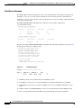
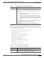
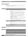
The command output in the following example shows two VCs for Ethernet over MPLS:
Router# show mpls l2transport vc
Local intf
Local circuit
Dest address
VC ID
Status
------------- -------------------- --------------- ---------- ---------Fa0/0.1
Eth VLAN 2
10.1.1.1
2
UP
Fa0/1
Ethernet
10.1.1.1
8
UP
VC 2 is in Ethernet VLAN mode. VC 8 is in Ethernet port mode.
Cisco 3825 Mobile Wireless Edge Router Software Configuration Guide
OL-15667-03
1-23
Chapter 1
Overview of the Cisco 3825 Mobile Wireless Edge Router
New Features in Cisco IOS Release 12.4(16)MR1
If you issue the show mpls l2transport vc detail command, the output is similar to the following:
Router# show mpls l2transport vc detail
Local interface: Fa0/0.1 up, line protocol up, Eth VLAN 2 up
Destination address: 10.1.1.1, VC ID: 2, VC status: up
.
.
.
Local interface: Fa0/1 up, line protocol up, Ethernet up
Destination address: 10.1.1.1, VC ID: 8, VC status: up
PWE3 over MLPPP
PWE3 over MLPPP (Multi-Link Point-to-Point Protocol) enables PWE3 establishment over multilink
backhaul. With this feature it is possible to use multilink as an MPLS or L2TPV3 (for ATM over
L2TPv3) enabled backhaul between two MWRs acting as PE routers. This feature does not need any
special configuration apart from enabling MPLS on MLPPP and using an MLPPP ip address for ip
routing between two MWRs acting as PE routers.
Existing command MPLS IP has been added to this feature to enable MPLS forwarding of IPv4 packets
along normally routed paths for a designated interface.
The following example illustrates that label switching is enabled on a designated Ethernet interface:
Router# configure terminal
Router(config)# interface multilink1
Router(config-if)# mpls ip
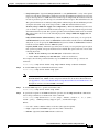
PWE3 Redundancy
The PWE3 Redundancy feature enables you to configure your network to detect a failure in the network
and reroute the Layer 2 (L2) service to another endpoint that can continue to provide service. This
feature provides the ability to recover from a failure of the PE router or the link between the PE and the
CE router.
Existing command backup peer has been added to this feature to specify a redundant peer for a PW VC.
Existing command backup delay has been added to this feature to specify how long a backup PW VC
should wait before resuming operation after the primary PW VC goes down.
Existing command xconnect logging redundancy has been added to this feature to enable system
message log (syslog) reporting of the status of the xconnect redundancy group.
The following example enables syslog reporting of the status of the xconnect redundancy group and
shows the messages that are generated during switchover events:
Router(config)# xconnect logging redundancy
Activating the Primary Member
00:01:07: %XCONNECT-5-REDUNDANCY: Activating primary member 10.55.55.2:1000
Activating the Backup Member:
00:01:05: %XCONNECT-5-REDUNDANCY: Activating secondary member 10.55.55.3:1001
Cisco 3825 Mobile Wireless Edge Router Software Configuration Guide
1-24
OL-15667-03
Chapter 1
Overview of the Cisco 3825 Mobile Wireless Edge Router
New Features in Cisco IOS Release 12.4(16)MR1
TDM PWE3 Redundancy
The following examples illustrate the use of the backup peer command:
PW Redundancy Without PW Class
interface CEM0/0/0
no ip address
cem 0
xconnect 2.2.2.2 100 encapsulation mpls
backup peer 2.2.2.2 200
backup delay 20 20
PW Redundancy With PW Class
pseudowire-class pw_redundancy
encapsulation mpls
interface CEM0/0/0
no ip address
cem 0
xconnect 2.2.2.2 100 encapsulation mpls
backup peer 2.2.2.2 200 pw-class pw_redundancy
backup delay 20 20
ATM PWE3 Redundancy
The following examples illustrate the use of the backup delay command:
PW Redundancy Without PW Class
interface ATM0/0/0
no ip address
xconnect 2.2.2.2 300 encapsulation mpls
backup peer 2.2.2.2 400
backup delay 20 20
PW Redundancy With PW Class
pseudowire-class pw_redundancy
encapsulation mpls
interface ATM0/0/0
no ip address
xconnect 2.2.2.2 300 encapsulation mpls
backup peer 2.2.2.2 400 pw-class pw_redundancy
backup delay 20 20
Ethernet PWE3 Redundancy
The following examples illustrate the use of the xconnect logging redundancy command:
PW Redundancy Without PW Class
interface GigabitEthernet 0/0
xconnect 2.2.2.2 500 encapsulation mpls
backup peer 2.2.2.2 600
backup delay 20 20
Cisco 3825 Mobile Wireless Edge Router Software Configuration Guide
OL-15667-03
1-25
Chapter 1
Overview of the Cisco 3825 Mobile Wireless Edge Router
New Features in Cisco IOS Release 12.4(16)MR1
PW Redundancy With PW Class
pseudowire-class pw_redundancy
encapsulation mpls
interface GigabitEthernet 0/0
xconnect 2.2.2.2 500 encapsulation mpls
backup peer 2.2.2.2 600 pw-class pw_redundancy
backup delay 20 20
Maximum Number of Supported ATM Ports
This enhancement increases the maximum number of supported ATM ports on the Cisco 3825 router.
The maximum number of ATM ports supported on the AIM-ATM-8 depends on the slot in which the
AIM-ATM-8 is installed:
•
AIM-ATM-8 installed in slot 0—maximum of 12 ATM ports supported
•
AIM-ATM-8 installed in slot 1—maximum of 8 ATM ports supported
The ATM-AIM module still supports a maximum of 4 ATM ports.
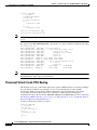
ATM Cell Switching
This feature provides PVC-to-PVC cell switching on the Cisco 3825 router.
The feature includes PVC remapping within either an AIM-ATM module or AIM-ATM-8 module. Also,
the feature is available for PVC-to-PVC switching between ATM interfaces and/or ATM IMA groups.
Note that PVC values must be above the well-known virtual path identifier/virtual channel identifier
(VPI/VCI) range (0/32).
The following configuration snippet shows a connection from ATM0/0/0 to ATM0/0/1. The PVC is
mapped from 0/32 to 0/33 and vice versa.
controller E1 0/0/0
mode atm aim 1
!
controller E1 0/0/1
mode atm aim 1
!
interface ATM0/0/0
pvc 0/32 12transport
!
interface ATM0/0/1
pvc 0/33 12transport
!
connection NAME a0/0 0/32 a0/1 0/33
Cisco 3825 Mobile Wireless Edge Router Software Configuration Guide
1-26
OL-15667-03
Chapter 1
Overview of the Cisco 3825 Mobile Wireless Edge Router
New Features in Cisco IOS Release 12.4(16)MR
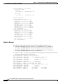
Privileged EXEC commands of interest include:
Router# show connection ?
all
All Connections
elements
Show Connection Elements
id
ID Number
name
Connection Name
port
Port Number
New Features in Cisco IOS Release 12.4(16)MR
With Cisco IOS Release 12.4(16)MR, the Cisco 3825 router supports the following:
•
GSMmux—Global System for Mobile Communication (GSM) Abis Optimization over IP,
page 1-27
•
UMTSmux—Universal Mobile Telecommunication System (UMTS) Iub Optimization over IP,
page 1-27
•
UMTS Congestion Management Control, page 1-28
•
Inverse Multiplexing over ATM (IMA), page 1-29
•
Permanent Virtual Circuit (PVC) Routing, page 1-30
•
UMTS QoS, page 1-33
GSMmux—Global System for Mobile Communication (GSM) Abis Optimization
over IP
The Cisco GSM Abis Optimization and Iub Optimization solutions can optimize the excess capacity that
exists in the current RAN backhaul network. This eliminates the need to add new T1/E1 trunks to meet
growing demand and can even allow a number of existing trunks to be decommissioned.
The Cisco GSM Abis Optimization over IP technology improves T1/E1 bandwidth efficiency by 33% to
50%, corresponding to a GSM voice call capacity gain of 50-100% per T1/E1, depending on the nature
of the traffic on the interface.
UMTSmux—Universal Mobile Telecommunication System (UMTS) Iub
Optimization over IP
The Cisco Iub Optimization over IP technology for R4/R99 (ATM) UMTS RANs improves bandwidth
efficiency by as much as 15 to 40%, corresponding to a UMTS voice call capacity gain of 18 to 67%,
depending on the type of Iub header and ATM Adaptation Layer traffic sub-cell multiplexing
performance. For R5/R6 IP UMTS RANs, Cisco provides compression and low-overhead encryption.
Cisco 3825 Mobile Wireless Edge Router Software Configuration Guide
OL-15667-03
1-27
Chapter 1
Overview of the Cisco 3825 Mobile Wireless Edge Router
New Features in Cisco IOS Release 12.4(16)MR
UMTS Congestion Management Control
The purpose of Congestion management control is to protect the most important traffic when congestion
happens. Typically signaling and voice traffic are configured as the highest priority in QoS, and usually
you do not expect these two types of combined traffic to congest the backhaul. But, if it does happen,
some traffic will be dropped. The QoS on the Cisco 3825 router does not differentiate between signaling
and voice traffic, which means the packets will drop randomly. Dropping signaling traffic could have
much more severe results than voice traffic. If the RNC and Node B lose signaling communication, the
Node B device could be reset. Signaling traffic needs to be passed through during this time. Congestion
management control throttles any other traffic but the signaling traffic, thus leaving the backhaul
resource for signaling traffic.
Typically, UMTS Congestion Management Control protects the most important PVC traffic (usually
signalling pvc) during backhaul congestion. Each PVC can be configured with a congestion priority.
There are nine congestion control priority levels, protected and priority 2- 9. The protected priority has
the highest priority and priority 9 has the lowest priority.
When congestion happens, all other PVC traffic except protected PVC(s) traffic will be throttled to save
the backhaul resource for the protected PVC traffic. If after a certain period (200 ms) and there is no
congestion reported, a recovery mechanism is triggered. Recovery gradually includes back throttled
PVC traffic in the order of their congestion control priority level (priority 2 being first and 9 being last).
Recovery will unthrottle the traffic gradually every until all traffic is recovered or congestion happens
again.
It is recommended that you configure UMTS QoS as your first line of defense when congestion happens
so that the low priority/best effort traffic be dropped by the QoS during congestion. Congestion control
will be triggered when combining priority traffic (signalling and voice) congested backhaul, and it will
throttle relatively less important traffic (voice) to protect most important traffic (signaling) based on the
congestion control priority configuration.
With UMTS Congestion Management Control, you can configure the UMTS congestion based on
priority. Two new commands (umts-iub congestion priority and umts-iub congestion-control) are
added using the PVC Configuration mode and Interface Configuration mode, respectively (see
Appendix A, “Cisco 3825 Mobile Wireless Edge Router RAN-O Command Reference”).
interface ATM0/IMA0
no ip address
atm bandwidth dynamic
atm umts-iub
no atm ilmi-keepalive
pvc 2/1 qsaal
umts-iub congestion priority
!
pvc 2/2
encapsulation aal0
umts-iub congestion priority
!
pvc 3/1
encapsulation aal0
umts-iub congestion priority
!
pvc 3/2
encapsulation aal0
umts-iub congestion priority
!
pvc 3/100
encapsulation aal2
!
umts-iub congestion-control
umts-iub set dscp 8
protected
protected
4
5
Cisco 3825 Mobile Wireless Edge Router Software Configuration Guide
1-28
OL-15667-03
Chapter 1
Overview of the Cisco 3825 Mobile Wireless Edge Router
New Features in Cisco IOS Release 12.4(16)MR
umts-iub set peering dscp 8
umts-iub local 20.20.20.21 6666
umts-iub remote 20.20.20.20 6666
One new CLI Show command show umts congestion atm slot/port has been added to this feature and
a new field has been added to the show umts-iub peering command (see Appendix A,
“Cisco 3825 Mobile Wireless Edge Router RAN-O Command Reference”).
The following example illustrates the use of show umts congestion atm.
Router# show umts congestion atm 0/ima0
UMTS-Iub(ATM0/IMA0):
Congestion: ON
Throttled ATM cells: 415801
Last congestion time: Mar 13 18:09:49.858
duration: 0h 0m 53s
The following example illustrates the use of show atm umts-iub peering command with the new
Congestion Control status field. In this example, it shows it On.
Router# show umts-iub peering atm 0/ima0
UMTS-Iub(ATM0/IMA0): Peering Information
UMTS-Iub(ATM0/IMA0 - ATM0/IMA1):
Local (20.20.20.21:6666) States:
UMTS-Iub(ATM0/IMA0 - ATM0/IMA1):
Connect State: OPEN
UMTS-Iub(ATM0/IMA0 - ATM0/IMA1):
Redundancy State: ACTIVE
UMTS-Iub(ATM0/IMA0 - ATM0/IMA1):
Congestion Control: ON
UMTS-Iub(ATM0/IMA0 - ATM0/IMA1):
Version: 4
UMTS-Iub(ATM0/IMA0 - ATM0/IMA1):
Alarm State:
UMTS-Iub(ATM0/0 - ATM0/2):
RX(NO ALARM)
TX(NO ALARM)
UMTS-Iub(ATM0/1 - ATM0/3):
RX(NO ALARM)
TX(NO ALARM)
UMTS-Iub(ATM0/IMA0 - ATM0/IMA1):
Remote (20.20.20.20:6666) States:
UMTS-Iub(ATM0/IMA0 - ATM0/IMA1):
Version: 4
UMTS-Iub(ATM0/IMA0 - ATM0/IMA1):
Alarm State:
UMTS-Iub(ATM0/0 - ATM0/2):
RX(NO ALARM)
TX(NO ALARM)
UMTS-Iub(ATM0/1 - ATM0/3):
RX(NO ALARM)
TX(NO ALARM)
Inverse Multiplexing over ATM (IMA)
Inverse Multiplexing over ATM (IMA) interface as a shorthaul enables you to configure existing UMTS
commands on IMA interfaces. No new commands are added for this new feature. Only previously
existing Cisco IOS commands have been added for this feature (see the “Configuring Inverse
Multiplexing over ATM (IMA)” section on page 4-37 and Appendix A, “Cisco 3825 Mobile Wireless
Edge Router RAN-O Command Reference”).
When operating in the IMA environment, a sample ATM configuration is written as follows:
interface ATM0/0/0
no ip address
no atm ilmi-keepalive
ima-group 0
scrambling-payload
interface ATM0/0/1
no ip address
no atm ilmi-keepalive
ima-group 0
scrambling-payload
Cisco 3825 Mobile Wireless Edge Router Software Configuration Guide
OL-15667-03
1-29
Chapter 1
Overview of the Cisco 3825 Mobile Wireless Edge Router
New Features in Cisco IOS Release 12.4(16)MR
interface ATM0/IMA0
no ip address
atm bandwidth dynamic
atm umts-iub
no atm ilmi-keepalive
pvc 2/1
encapsulation aal0
!
pvc 2/2
encapsulation aal0
!
umts-iub local 20.20.20.21 6666
umts-iub remote 20.20.20.20 6666
Note
The above sample configuration has one IMA shorthaul with two member links (atm0/0/0
0/0/1 ).
and atm
The output for the show umts-iub peering command has also changed and will look like the following:
Router#show umts peer
UMTS-Iub(ATM0/IMA0 - ATM0/IMA0): Peering Information
UMTS-Iub(ATM0/IMA0 - ATM0/IMA0):
Local (20.20.20.21:6666) States:
UMTS-Iub(ATM0/IMA0 - ATM0/IMA0):
Connect State: OPEN
UMTS-Iub(ATM0/IMA0 - ATM0/IMA0):
Redundancy State: ACTIVE
UMTS-Iub(ATM0/IMA0 - ATM0/IMA0):
Version: 4
UMTS-Iub(ATM0/IMA0 - ATM0/IMA0):
Alarm State:
UMTS-Iub(ATM0/0/0 - ATM0/0/0): RX(NO ALARM) TX(NO ALARM)
UMTS-Iub(ATM0/0/1 - ATM0/0/1): RX(NO ALARM) TX(NO ALARM)
UMTS-Iub(ATM0/IMA0 - ATM0/IMA0):
Remote (20.20.20.20:6666) States:
UMTS-Iub(ATM0/IMA0 - ATM0/IMA0):
Version: 4
UMTS-Iub(ATM0/IMA0 - ATM0/IMA0):
Alarm State:
UMTS-Iub(ATM0/0/0 - ATM0/0/0):
RX(NO ALARM)
TX(NO ALARM)
UMTS-Iub(ATM0/0/1 - ATM0/0/1):
RX(NO ALARM)
TX(NO ALARM)
Note
In the previous output, the local shorthaul/interface name appears before the dash (–), and the remote
shorthaul/interface name appears after the dash (–).
Permanent Virtual Circuit (PVC) Routing
PVC Routing allows you to offload PVC traffic from a physical ATM shorthaul to an alternate backhaul.
For each alternate backhaul, you will need to create a logical shorthaul by creating an ATM
sub-interface. Traffic from the PVCs configured under this logical shorthaul will go through the
corresponding alternate backhaul. Three new commands are added using the Sub-interface
Configuration mode for this new feature: atm umts, umts local, and umts remote (see the “Configuring
PVC Routing (HSDPA Offload)” section on page 4-41 and Appendix A, “Cisco 3825 Mobile Wireless
Edge Router RAN-O Command Reference”).
A sample configuration is written as follows:
interface ATM0/IMA0
no ip address
atm umts-iub
no atm ilmi-keepalive
pvc 2/1
encapsulation aal0
!
pvc 2/2
Cisco 3825 Mobile Wireless Edge Router Software Configuration Guide
1-30
OL-15667-03
Chapter 1
Overview of the Cisco 3825 Mobile Wireless Edge Router
New Features in Cisco IOS Release 12.4(16)MR
encapsulation aal0
!
umts-iub local 20.20.20.21 6666
umts-iub remote 20.20.20.20 6666
interface ATM0/IMA0.1 multipoint
atm umts-iub
pvc 1/200
encapsulation aal0
!
umts-iub local 192.168.10.2
umts-iub remote 192.168.10.1
In the above sample, traffic for PVC 1/200 will be off-loaded to the alternate backhaul (192.168.10.2 -192.168.10.1). The new output of a show umts peer command will look like the following:
Router#show umts peer
UMTS-Iub(ATM0/IMA0 - ATM0/IMA0): Peering Information
UMTS-Iub(ATM0/IMA0 - ATM0/IMA0):
Local (20.20.20.21:6666) States:
UMTS-Iub(ATM0/IMA0 - ATM0/IMA0):
Connect State: OPEN
UMTS-Iub(ATM0/IMA0 - ATM0/IMA0):
Redundancy State: ACTIVE
UMTS-Iub(ATM0/IMA0 - ATM0/IMA0):
Version: 4
UMTS-Iub(ATM0/IMA0 - ATM0/IMA0):
Alarm State:
UMTS-Iub(ATM0/0/0 - ATM0/0/0): RX(NO ALARM) TX(NO ALARM)
UMTS-Iub(ATM0/0/1 - ATM0/0/1): RX(NO ALARM) TX(NO ALARM)
UMTS-Iub(ATM0/IMA0 - ATM0/IMA0):
Remote (20.20.20.20:6666) States:
UMTS-Iub(ATM0/IMA0 - ATM0/IMA0):
Version: 4
UMTS-Iub(ATM0/IMA0 - ATM0/IMA0):
Alarm State:
UMTS-Iub(ATM0/0/0 - ATM0/0/0):
RX(NO ALARM)
TX(NO ALARM)
UMTS-Iub(ATM0/0/1 - ATM0/0/1):
RX(NO ALARM)
TX(NO ALARM)
UMTS-Iub(ATM0/IMA0.1
UMTS-Iub(ATM0/IMA0.1
UMTS-Iub(ATM0/IMA0.1
UMTS-Iub(ATM0/IMA0.1
UMTS-Iub(ATM0/IMA0.1
UMTS-Iub(ATM0/IMA0.1
UMTS-Iub(ATM0/IMA0.1
Note
-
ATM0/IMA.1): Peering Information
ATM0/IMA.1):
Local (192.168.10.2:6666) States:
ATM0/IMA.1):
Connect State: OPEN
ATM0/IMA.1):
Redundancy State: ACTIVE
ATM0/IMA.1):
Version: 4
ATM0/IMA.1):
Remote (192.168.10.1:6666) States:
ATM0/IMA.1):
Version: 4
In the previous output, the local shorthaul/interface name appears before the dash (–), and the remote
shorthaul/interface name appears after the dash (–).
Router#show umts pvc
UMTS-Iub(ATM0/IMA0): PVC matching
Peering state: OPEN
Local PVCs:
PVC(2/1): has
MATCHING remote PVC.
PVC(2/2): has
MATCHING remote PVC.
Remote PVCs:
PVC(2/1): has
PVC(2/2): has
MATCHING local PVC.
MATCHING local PVC.
Cisco 3825 Mobile Wireless Edge Router Software Configuration Guide
OL-15667-03
1-31
Chapter 1
Overview of the Cisco 3825 Mobile Wireless Edge Router
New Features in Cisco IOS Release 12.4(16)MR
UMTS-Iub(ATM0/IMA0.1): PVC matching
Peering state: OPEN
Local PVCs:
PVC(1/200): has
MATCHING remote PVC.
Remote PVCs:
PVC(1/200): has
MATCHING local PVC.
Lisa#show umts packet
UMTS-Iub(ATM0/IMA0): packets:
rxUMTS_count ================
txUMTS_count ================
rxUMTS_bytes ================
txUMTS_bytes ================
rxBackhaul_packets ==========
txBackhaul_packets ==========
rxBackhaul_bytes ============
txBackhaul_bytes ============
Last cleared 00:50:39
UMTS-Iub(ATM0/IMA0.1): packets:
rxUMTS_count ================
txUMTS_count ================
rxUMTS_bytes ================
txUMTS_bytes ================
rxBackhaul_packets ==========
txBackhaul_packets ==========
rxBackhaul_bytes ============
txBackhaul_bytes ============
Last cleared 00:08:08
468845
276847
22504560
13288656
58216
88884
14687104
24824360
126173
126173
6056304
6056304
28405
28777
6532571
7596968
Behavior Changes
The following behavior changes will be apparent when using this PVC Routing feature.
1.
When the no atm umts command is applied to a base ATM interface, the command will
un-configure the ATM UMTS mode for all the sub-interfaces under that ATM interface.
2.
When the no atm umts command is applied to an ATM sub-interface, the command will
un-configure the ATM UMTS mode only for that sub-interface.
3.
Alarms are carried over the primary backhaul only, while the primary peering will have the alarm
information. The following is a sample output:
UMTS-Iub(ATM0/IMA0 - ATM0/IMA0): Peering Information
UMTS-Iub(ATM0/IMA0 - ATM0/IMA0):
Local (20.20.20.21:6666) States:
UMTS-Iub(ATM0/IMA0 - ATM0/IMA0):
Connect State: OPEN
UMTS-Iub(ATM0/IMA0 - ATM0/IMA0):
Redundancy State: ACTIVE
UMTS-Iub(ATM0/IMA0 - ATM0/IMA0):
Version: 4
UMTS-Iub(ATM0/IMA0 - ATM0/IMA0):
Alarm State:
UMTS-Iub(ATM0/0/0 - ATM0/0/0): RX(NO ALARM) TX(NO ALARM)
UMTS-Iub(ATM0/0/1 - ATM0/0/1): RX(NO ALARM) TX(NO ALARM)
UMTS-Iub(ATM0/IMA0 - ATM0/IMA0):
Remote (20.20.20.20:6666) States:
UMTS-Iub(ATM0/IMA0 - ATM0/IMA0):
Version: 4
UMTS-Iub(ATM0/IMA0 - ATM0/IMA0):
Alarm State:
UMTS-Iub(ATM0/0/0 - ATM0/0/0):
RX(NO ALARM)
TX(NO ALARM)
UMTS-Iub(ATM0/0/1 - ATM0/0/1):
RX(NO ALARM)
TX(NO ALARM)
Cisco 3825 Mobile Wireless Edge Router Software Configuration Guide
1-32
OL-15667-03
Chapter 1
Overview of the Cisco 3825 Mobile Wireless Edge Router
New Features in Cisco IOS Release 12.4(16)MR
UMTS-Iub(ATM0/IMA0.1
UMTS-Iub(ATM0/IMA0.1
UMTS-Iub(ATM0/IMA0.1
UMTS-Iub(ATM0/IMA0.1
UMTS-Iub(ATM0/IMA0.1
UMTS-Iub(ATM0/IMA0.1
UMTS-Iub(ATM0/IMA0.1
Note
-
ATM0/IMA.1): Peering Information
ATM0/IMA.1):
Local (192.168.10.2:6666) States:
ATM0/IMA.1):
Connect State: OPEN
ATM0/IMA.1):
Redundancy State: ACTIVE
ATM0/IMA.1):
Version: 4
ATM0/IMA.1):
Remote (192.168.10.1:6666) States:
ATM0/IMA.1):
Version: 4
In the previous output, the local shorthaul/interface name appears before the dash (–), and the remote
shorthaul/interface name appears after the dash (–).
4.
An admin shutdown of the base ATM interface will shut down all the peering instances, including
the primary peering and all the sub-interface peering(s). (In other words, they will move to the
CLOSED state).
5.
An admin shutdown of an ATM sub-interface will shut down only the peering for that
sub-interface. (In other words, the admin shutdown of the ATM sub-interface will make the PVCs
on that sub-interface inactive, but it won’t change the status of the PVCs on the other end of the
shorthaul, Node B or RNC.)
6.
When the primary backhaul goes down and the primary peering goes down, the primary peering will
start sending Alarm Indication Signals (AISs) on the shorthaul, and; therefore, bring down the
shorthaul like before. So all shorthaul traffic will stop, including the PVC traffic off-loaded to the
alternate backhaul(s). (In this situation, the sub-interface peering connection state will stay OPEN
as long as the alternate backhaul doesn’t go down).
7.
When an alternate or sub-interface backhaul goes down, the sub-interface peering will go down, but
it won’t bring down the shorthaul or start any alarms on the T1/E1 link. So primary backhaul traffic
won’t be affected. (In this case, the sub-interface’s state will not be changed since the sub-interface
is only the logical interface and changing its state will not generate any notification to the Node B
or RNC at the ATM level. If the Node B/RNC wants to be able to detect an alternate backhaul down
situation, configure the OAM-CC on the PVCs that are off-loaded to the alternate/sub-interface
backhaul).
8.
Cannot configure the qsaal type PVC under the ATM sub-interface, which means the AAL5 type
traffic cannot be off-loaded to the alternate backhaul unless they are configured as the AAL0 type
on the Cisco 3825 router.
UMTS QoS
Three new commands are added using the Interface Configuration mode for this new feature: umts-iub
set dscp, umts-iub set peering dscp, and gsm-abis set dscp and one new ATM-VC Interface
Configuration command: umts-iub set dscp (see the “Configuring UMTS QoS” section on page 4-46
and Appendix A, “Cisco 3825 Mobile Wireless Edge Router RAN-O Command Reference”). These new
commands allow you to perform the following:
•
UMTS Shorthaul Interface
– Set the default description value to tag the backhaul packet including peering and data generated
from the shorthaul in a UMTS Iub configuration.
– Set the description value in the UMTS Iub configuration such that it overwrites the default value
defined previously. It is also used to tag the peering backhaul packet.
Cisco 3825 Mobile Wireless Edge Router Software Configuration Guide
OL-15667-03
1-33
Chapter 1
Overview of the Cisco 3825 Mobile Wireless Edge Router
New Features in Cisco IOS Release 12.4(16)MR
•
PVC of a UMTS Shorthaul Interface
– Set the description value in the UMTS Iub configuration such that it overwrites the default value
defined previously. It is also used to tag the backhaul packet generated from traffic from the
PVC.
•
GSM Shorthaul Interface
– Set the description value in such a way as to tag all the backhaul packets generated from the
shorthaul in the GSM Abis interface.
A sample configuration is written as follows:
class-map match-any llq-class
match ip dscp cs2
!
policy-map llq-policy
class llq-class
priority percent 99
class class-default
bandwidth remaining percent 1
queue-limit 45
!
interface ATM0/0/0
no ip address
atm umts-iub
no atm ilmi-keepalive
pvc 2/1
encapsulation aal0
umts-iub set dscp 16
!
pvc 2/2
encapsulation aal0
!
umts-iub set dscp 8
umts-iub set peering dscp 16
umts-iub local 20.20.20.21 6666
umts-iub remote 20.20.20.20 6666
!
interface ATM0/0/1
no ip address
atm umts-iub
no atm ilmi-keepalive
pvc 2/1
encapsulation aal0
umts-iub set dscp 16
!
pvc 2/2
encapsulation aal0
!
umts-iub set dscp 8
umts-iub set peering dscp 16
umts-iub local 20.20.20.21 8888
umts-iub remote 20.20.20.20 8888
interface Multilink2
ip address 20.20.20.21 255.255.255.0
ip tcp header-compression ietf-format
load-interval 30
no keepalive
no cdp enable
ppp pfc local request
ppp pfc remote apply
Cisco 3825 Mobile Wireless Edge Router Software Configuration Guide
1-34
OL-15667-03
Chapter 1
Overview of the Cisco 3825 Mobile Wireless Edge Router
New Features in Cisco IOS Release 12.4(16)MR
ppp acfc local request
ppp acfc remote apply
ppp multilink
ppp multilink interleave
ppp multilink group 2
ppp multilink fragment delay 0 1
ppp multilink multiclass
max-reserved-bandwidth 100
service-policy output llq-policy
hold-queue 50 out
ip rtp header-compression ietf-format
In the above sample, PVC 2/1 of ATM0/0/0 and ATM0/0/1 will go to the priority queue and PVC 2/2 of
ATM0/0/0 and ATM0/0/1 will be considered the best effort traffic and will go to the Weighted Fair
Queue.
Note
Defining the dscp value under the PVC affects the way the ATM cells are bundled together as a backhaul.
The more dscp values that are defined, the more limitations on how the ATM cells can be bundled. This,
as a result, could affect backhaul efficiency. We recommend that you define at most two different dscp
values for each shorthaul. One for llq traffic, and the other for best effort traffic.
Cisco 3825 Mobile Wireless Edge Router Software Configuration Guide
OL-15667-03
1-35
Chapter 1
Overview of the Cisco 3825 Mobile Wireless Edge Router
New Features in Cisco IOS Release 12.4(16)MR
Cisco 3825 Mobile Wireless Edge Router Software Configuration Guide
1-36
OL-15667-03
CH A P T E R
2
Cisco IOS Software Basics
This chapter describes what you need to know about the Cisco IOS software before you configure the
router by using the CLI. This chapter includes the following topics:
•
Getting Help, this page
•
Understanding Command Modes, page 2-2
•
Undoing a Command or Feature, page 2-3
•
Saving Configuration Changes, page 2-3
•
Where to Go Next, page 2-3
Understanding this information will save you time as you begin to use the CLI. If you have never used
the Cisco IOS software or if you need a refresher, read this chapter before you proceed to Chapter 3,
“First-Time Configuration.”
If you are already familiar with the Cisco IOS software, proceed to Chapter 3, “First-Time
Configuration”.
Getting Help
Use the question mark (?) and arrow keys to help you enter commands:
•
For a list of available commands, enter a question mark:
Router> ?
•
To complete a command, enter a few known characters followed by a question mark (with no space):
Router> s?
•
For a list of command variables, enter the command followed by a space and a question mark:
Router> show ?
•
To redisplay a command that you previously entered, press the Up Arrow key. Continue to press the
Up Arrow key to see more commands.
Cisco 3825 Mobile Wireless Edge Router Software Configuration Guide
OL-15667-03
2-1
Chapter 2
Cisco IOS Software Basics
Understanding Command Modes
Understanding Command Modes
The Cisco IOS user interface is used in various command modes. Each command mode permits you to
configure different components on your router. The commands available at any given time depend on
which command mode you are in. Entering a question mark (?) at a prompt displays a list of commands
available for that command mode. Table 2-1 lists the most common command modes.
Table 2-1
Timesaver
Common Command Modes
Command Mode
Access Method
Router Prompt
Displayed
Exit Method
User EXEC
Log in.
Router>
Use the logout command.
Privileged EXEC
From user EXEC mode,
enter the enable
command.
Router#
To exit to user EXEC
mode, use the disable,
exit, or logout command.
Global configuration
From the privileged
EXEC mode, enter the
configure terminal
command.
Router (config)#
To exit to privileged
EXEC mode, use the exit
or end command, or press
Ctrl-Z.
Interface configuration
From the global
configuration mode,
enter the interface type
number command, such
as interface serial
0/0/0.
Router (config-if)#
To exit to global
configuration mode, use
the exit command.
To exit directly to
privileged EXEC mode,
press Ctrl-Z.
Each command mode restricts you to a subset of commands. If you have trouble entering a command,
check the prompt and enter the question mark (?) to see a list of available commands. You might be in
the wrong command mode or be using an incorrect syntax.
In the following example, notice how the prompt changes after each command to indicate a new
command mode:
Router> enable
Password: <enable password>
Router# configure terminal
Router (config)# interface serial 0/0/0
Router (config-if)# line 0
Router (config-line)# controller t1 0
Router (config-controller)# exit
Router (config)# exit
Router#
%SYS-5-CONFIG_I: Configured from console by console
The last message is normal and does not indicate an error. Press Return to get the Router# prompt.
Note
You can press Ctrl-Z in any mode to immediately return to enable mode (Router#), instead of entering
exit, which returns you to the previous mode.
Cisco 3825 Mobile Wireless Edge Router Software Configuration Guide
2-2
OL-15667-03
Chapter 2
Cisco IOS Software Basics
Undoing a Command or Feature
Undoing a Command or Feature
If you want to undo a command that you entered or if you want to disable a feature, enter the keyword
no before most commands; for example, no ip routing.
Saving Configuration Changes
You must enter the copy running-config startup-config command to save your configuration changes
to NVRAM, so that the changes are not lost if there is a system reload or power outage. For example:
Router# copy running-config startup-config
Building configuration...
It might take a few minutes to save the configuration to nonvolatile random-access memory (NVRAM).
After the configuration has been saved, the following message appears:
[OK]
Router#
Where to Go Next
Now that you know some Cisco IOS software basics, you can begin to configure the router by using the
CLI.
Remember the following:
•
You can use the question mark (?) and arrow keys to help you enter commands.
•
Each command mode restricts you to a set of commands. If you have difficulty entering a command,
check the prompt and then enter the question mark (?) to see a list of available commands. You might
be in the wrong command mode or be using the incorrect syntax.
•
To disable a feature, enter the keyword no before the command; for example, no ip routing.
•
You need to save your configuration changes to NVRAM so that the changes are not lost if there is
a system reload or power outage.
Proceed to Chapter 3, “First-Time Configuration,” for first time configuration. Otherwise, proceed to
Chapter 4, “Configuring the Cisco 3825 Mobile Wireless Edge Router in a RAN-O Solution with the
Command-Line Interface,” to begin configuring the router.
Cisco 3825 Mobile Wireless Edge Router Software Configuration Guide
OL-15667-03
2-3
Chapter 2
Cisco IOS Software Basics
Where to Go Next
Cisco 3825 Mobile Wireless Edge Router Software Configuration Guide
2-4
OL-15667-03
CH A P T E R
3
First-Time Configuration
This chapter contains information with which you should be familiar before you begin to configure your
router for the first time, including information about understanding boot images, interface numbering,
and what you should do before you turn on your router. This chapter also describes how to use the setup
command facility to configure your Cisco 3825 Mobile Wireless Edge Router.
This chapter includes the following sections:
•
Setup Command Facility, page 3-3
•
Configuring Global Parameters, page 3-4
•
Completing the Configuration, page 3-7
Understanding Boot Images
The first file on the compact flash device in slot0: must be the Cisco IOS software image that you want
to use. If it is not, the Cisco 3825 router will not be able to boot.
Understanding the Cisco 3825 Router Interface Numbering
Each network interface on a Cisco 3825 router is identified by a slot number, subslot number, and a port
number.
Figure 3-1 on page 3-2 shows an example of interface numbering on a Cisco 3825 router:
•
A Cisco 2-port T1/E1-RAN interface card in each of the four Cisco 2-port T1/E1-RAN slots (labeled
HWIC0, HWIC1, HWIC2, and HWIC3) [high-speed WIC]
•
Two built-in Gigabit Ethernet (GE) interfaces (labeled GE 0/0 and GE 0/1)
Cisco 3825 Mobile Wireless Edge Router Software Configuration Guide
OL-15667-03
3-1
Chapter 3
First-Time Configuration
Understanding the Cisco 3825 Router Interface Numbering
Figure 3-1
Cisco 3825 Router Slot and Port Numbers
Network module
(NME) slot 2
NMDESW36
Removable
face plate
Console Gigabit Ethernet
(GIGE) ports
port
GE 0/0
GE 0/1
35x
GE1
FastEthern
et Ports
280205
10/100/100
Base-Tx 0
17x
Network module
(NME) slot 1
High-speed WIC
(HWIC) slots
HWIC3 HWIC2
HWIC1 HWIC0
Auxiliary Small Form Pluggable
port
(SFP) port
Slot and Port Numbering
The Cisco 3825 router chassis contains the following LAN and WAN interface types:
•
One Small Form Pulggable (SFP) port—industry standard Gigabit interface convertor
•
Two built-in Gigabit Ethernet LAN interfaces (labeled GE 0/0 and GE 0/1)
•
Four slots for installing Cisco 2-port T1/E1-RAN interface cards (labeled HWIC0, HWIC1,
HWIC2, and HWIC3)
•
Two slots for installing NM-2W network modules (supports up to four additional
Cisco 2-port T1/E1-RAN interface cards)
Note
A removable face plate allows for installation of a double-wide NMD network module into NME
slot 2.
The logical slot numbers are as follows:
•
0 for all built-in Cisco 2-port T1/E1-RAN interface card slots
•
1 for the lower network module slot
•
2 for the upper network module slot
The numbering format is:
<Interface type> <Slot number> / <Subslot number> / <Port number>
For example:
Serial 0/0/0 (HWIC slot 0)
Serial 1/0/0 (NM slot 1)
Cisco 3825 Mobile Wireless Edge Router Software Configuration Guide
3-2
OL-15667-03
Chapter 3
First-Time Configuration
Setup Command Facility
Interface (port) numbers begin at logical 0 for each interface type; ports are numbered from right to left.
•
The two built-in Gigabit Ethernet 10/100/1000 logical interfaces are GE 0/0 and GE 0/1.
•
The logical slot number for all Cisco 2-port T1/E1-RAN interfaces in the built-in
Cisco 2-port T1/E1-RAN interface card slot is always 0. (The HWIC0, HWIC1, HWIC2, and
HWIC3 slot designations are for physical slot identification only.) Interfaces in the
Cisco 2-port T1/E1-RAN interface cards are numbered from right to left, starting with logical 0/0/0
for each interface type, regardless of the physical slot in which the Cisco 2-port T1/E1-RAN
interface cards are installed.
For example, if you have a Cisco 2-port T1/E1-RAN interface card in two of the 2-port T1/E1-RAN
interface card slots (physical slots HWIC0 and HWIC1), then the logical interfaces are:
– Serial 0/0/0 and Serial 0/0/1 in physical slot HWIC0
– Serial 0/1/0 and Serial 0/1/1 in physical slot HWIC1
However, if you install a Cisco 2-port T1/E1-RAN interface card in physical slot HWIC1 (leaving
slot HWIC0 empty), the logical interfaces in slot HWIC1 are Serial 0/0/0 and Serial 0/0/1. If you
later add a Cisco 2-port T1/E1-RAN interface card to slot HWIC0, the interface numbering will
shift. The configuration that you created for logical interfaces Serial 0/0/0 and Serial 0/0/1 will now
be applied to the Cisco 2-port T1/E1-RAN interface card in slot HWIC0, and you will need to create
a new configuration for the interfaces that you previously configured on HWIC1 (which will now
be Serial 0/1/0 and Serial 0/1/1).
•
The slot number of the Cisco 2-port T1/E1-RAN interfaces installed in slot 1 using an NM-2W
network module is always logical 1, and the interfaces are always numbered from the right to left.
Setup Command Facility
The setup command facility prompts you for information that is needed to start a router functioning
quickly. The facility steps you through a basic configuration, including LAN interfaces.
If you prefer to configure the router manually or if you wish to configure a module or interface that is
not included in the setup command facility, proceed to “Chapter 2, “Cisco IOS Software Basics” to
familiarize yourself with the command-line interface (CLI) and then proceed to Chapter 4, “Configuring
the Cisco 3825 Mobile Wireless Edge Router in a RAN-O Solution with the Command-Line Interface”
for instructions on configuring your Cisco 3825 router.
Before Starting Your Router
Before you power on your router and begin using the setup command facility, follow these steps:
Step 1
Set up the hardware and connect the console and network cables as described in the “Connecting Cables
to Cisco 3800 Series Routers” section of the Cisco 3800 Series Hardware Installation guide.
Step 2
Configure your PC terminal emulation program for 9600 baud, 8 data bits, no parity, and 1 stop bit.
Cisco 3825 Mobile Wireless Edge Router Software Configuration Guide
OL-15667-03
3-3
Chapter 3
First-Time Configuration
Configuring Global Parameters
Using the Setup Command Facility
The setup command facility is displayed in your PC terminal emulation program window.
To create a basic configuration for your router, do the following:
Note
•
Complete the steps in the “Configuring Global Parameters” section on page 3-4.
•
Complete the steps in the “Completing the Configuration” section on page 3-7.
If you make a mistake while using the setup command facility, you can exit the facility and run it again.
Press Ctrl-C, and type setup at the enable mode prompt (1900#).
Configuring Global Parameters
Step 1
Power on the router.
Messages will begin to appear in your terminal emulation program window.
Caution
Do not press any keys on the keyboard until the messages stop. Any keys that you press during this time
will be interpreted as the first command entered after the messages stop, which might cause the router
to power off and start over. Wait a few minutes. The messages will stop automatically.
The messages look similar to the following:
Note
The messages vary, depending on the Cisco IOS software image and interface modules in your
router. The screen displays in this section are for reference only and might not match the
messages on your console.
rommon 1 >boot
program load complete, entry point: 0x8000f000, size: 0xc0c0
Initializing ATA monitor library.......
program load complete, entry point: 0x80010000, size: 0x2888ab0
Self decompressing the image :
############################################################################
[OK]
Smart Init is enabled
smart init is sizing iomem
ID
MEMORY_REQ
TYPE
00042A
0X010D78F3 C3825 motherboard
0000D6
0X000D8A10 FE Port Module, 2 WAN
0000D6
0X000D8A10 FE Port Module, 2 WAN
0X00288860 Onboard PVDM2 SIMM
0X000021B8 OnboardUSB
000587
0X0030FEF2 ATM AIM-8 with SAR only, no DSPs
000587
0X0030FEF2 ATM AIM-8 with SAR only, no DSPs
0X00660670 public buffer pools
0X0078F000 public particle pools
TOTAL:
0X02922B7F
Cisco 3825 Mobile Wireless Edge Router Software Configuration Guide
3-4
OL-15667-03
Chapter 3
First-Time Configuration
Configuring Global Parameters
If any of the above Memory requirements
are “UNKNOWN”, you may be using an unsupported
configuration or there is a software problem and
system operation may be compromised.
Rounded IOMEM up to: 42Mb.
Using 8 percent iomem. [42Mb/512Mb]
Restricted Rights Legend
Use, duplication, or disclosure by the Government is
subject to restrictions as set forth in subparagraph
(c) of the Commercial Computer Software - Restricted
Rights clause at FAR sec. 52.227-19 and subparagraph
(c) (1) (ii) of the Rights in Technical Data and Computer
Software clause at DFARS sec. 252.227-7013.
cisco Systems, Inc.
170 West Tasman Drive
San Jose, California 95134-1706
Cisco IOS Software, 3800 Software (C3825-IPRANK9-M), Version 12.4(16)MR1, RELEASE SOFTWARE
(fc1)
Technical Support: http://www.cisco.com/techsupport
Copyright (c) 1986-2008 by Cisco Systems, Inc.
Compiled Thu 10-Jan-08 14:09 by prod_rel_team
Image text-base: 0x600010930, data-base: 0x62C1F030
This product contains cryptographic features and is subject to United
States and local country laws governing import, export, transfer and
use. Delivery of Cisco cryptograhpic products does not imply
third-party authority to import, export, distribute or use encryption.
Importers, exporters, distributors and users are responsible for
compliance with U.S. and local country laws. By using this product you
agree to comply with applicable laws and regulations. If you are unable
to comply with U.S. and local laws, return this product immediately.
A summary of U.S. laws governing Cisco cryptographic products may be found at:
http://www.cisco.com/wwl/export/crypto/tool/stqrg.html
If you require further assistance please contact us by sending email to
[email protected].
Cisco 3825 (revision 1.0) with 481280K/43008K bytes of memory.
Processor board ID FHK0902F51G
2 Gigabit Ethernet interfaces
16 Channelized (E1 or T1)/PRI ports
2 ATM/Voice AIMs
DRAM configuration is 64 bits wide with parity disabled.
479K bytes of NVRAM.
125440K bytes of ATA System CompactFlash (Read/Write)
Step 2
When the following message appears, enter yes to begin the initial configuration dialog:
Basic management setup configures only enough connectivity
for management of the system, extended setup will ask you
to configure each interface on the system
Would you like to enter basic management setup? [yes/no]:yes
Configuring global parameters:
Cisco 3825 Mobile Wireless Edge Router Software Configuration Guide
OL-15667-03
3-5
Chapter 3
First-Time Configuration
Configuring Global Parameters
Step 3
Enter a hostname for the router (this example uses 3825-1):
Configuring global parameters:
Enter host name [Router]: 3825-1
Step 4
Enter an enable secret password. This password is encrypted (more secure) and cannot be seen when
viewing the configuration:
The enable secret is a password used to protect access to
privileged EXEC and configuration modes. This password, after
entered, becomes encrypted in the configuration.
Enter enable secret: ciscoenable
Note
Step 5
When you enter the enable secret password, it will be seen while you type the password. After entering
it, it becomes encrypted in the configuration.
Enter an enable password that is different from the enable secret password. This password is not
encrypted (less secure) and can be seen when viewing the configuration:
The enable password is used when you do not specify an
enable secret password, with some older software versions, and
some boot images.
Enter enable password: ciscoenable
Step 6
Enter the virtual terminal password, which prevents unauthenticated access to the router through ports
other than the console port:
The virtual terminal password is used to protect
access to the router over a network interface.
Enter virtual terminal password: ciscoterminal
Step 7
Respond to the following prompts as appropriate for your network:
Configure SNMP Network Management? [yes]:
Community string [public]: public
Step 8
The summary of interfaces is displayed. This list varies, depending on what network modules, if any, are
installed in your router.
Current interface summary
Any interface listed with OK? value “NO” does not have a valid configuration
Interface
GigabitEthernet0/0
GigabitEthernet0/1
Step 9
IP-Address
unassigned
unassigned
OK? Method Status
NO unset up up
NO unset up up
Protocol
Specify the interface to be used to connect to the network management system.
Enter interface name used to connect to the
management network from the above interface summary: GigabitEthernet0/0
Cisco 3825 Mobile Wireless Edge Router Software Configuration Guide
3-6
OL-15667-03
Chapter 3
First-Time Configuration
Completing the Configuration
Step 10
Configure the specified interface as prompted.
Configuring interface GigabitEthernet0/0:
Use the 100 Base-TX (RJ-45) connector? [yes]: yes
Operate in full-duplex mode? [no]: yes
Configure IP on this interface? [yes]:yes
IP address for this interface: 178.18.44.233
Subnet mask for this interface [255.255.0.0] : 255.255.255.128
Class B network ia 178.18.0.0, 25 subnet bits; mask is /25
Completing the Configuration
When you have provided all the information prompted for by the setup command facility, the
configuration appears. Messages will be displayed that are similar to the following:
The following configuration command script was created:
!
hostname 3825-1
enable secret 5 $1$5fH0$Z6Pr5EgtR5iNJ2nBg3i6y1 enable password ciscoenable line vty 0 4
password ciscoenablesnmp-server community public !
no ip routing
!
interface GigabitEthernet0/0
no shutdown
media-type 100BaseX
full-duplex
ip address 178.18.44.233 255.255.255.128
!
interface GigabitEthernet0/1
shutdown
no ip address
!
end
To complete your router configuration, do the following:
Step 1
A setup command facility prompt asks whether you want to save this configuration.
[0] Go to the IOS command prompt without saving this config.
[1] Return back to the setup without saving this config.
[2] Save this configuration to nvram and exit.
Enter your selection [2]: 2
Building configuration...
[OK]
Use the enabled mode 'configure' command to modify this configuration.
Press RETURN to get started!
Cisco 3825 Mobile Wireless Edge Router Software Configuration Guide
OL-15667-03
3-7
Chapter 3
First-Time Configuration
Completing the Configuration
If you answer no, the configuration information that you entered is not saved, and you return to the router
enable prompt. Type setup to return to the System Configuration Dialog.
If you answer yes, the configuration is saved, and you return to the EXEC prompt.
Step 2
When the messages stop displaying on your screen, press Return to get the command line prompt.
The 3825-1> prompt indicates that you are now at the CLI and you have just completed a basic router
configuration. However, this is not a complete configuration. You must configure additional parameters
by using the Cisco IOS software CLI as described in Chapter 4, “Configuring the Cisco 3825 Mobile
Wireless Edge Router in a RAN-O Solution with the Command-Line Interface.”
Cisco 3825 Mobile Wireless Edge Router Software Configuration Guide
3-8
OL-15667-03
CH A P T E R
4
Configuring the Cisco 3825 Mobile Wireless
Edge Router in a RAN-O Solution with the
Command-Line Interface
This chapter describes how to use the Cisco IOS software CLI to configure the Cisco 3825 Mobile
Wireless Edge Router in a Radio Access Network-Optimization (RAN-O) solution and includes the
following sections:
•
Before You Begin, page 4-2
•
Verifying the Version of Cisco IOS Software, page 4-2
•
Clocking Requirements for Cisco 3825 Router, page 4-2
•
Show Controller Command, page 4-5
•
Configuration Sequence, page 4-6
•
Configuring the Hostname and Password, page 4-6
•
Configuring Gigabit Ethernet Interfaces, page 4-8
•
Configuring the Backhaul Links, page 4-9
•
Configuring GSM-Abis Links, page 4-20
•
Configuring UMTS Links, page 4-24
•
Configuring Redundancy, page 4-28
•
Configuring for SNMP Support, page 4-33
•
Configuring Inverse Multiplexing over ATM (IMA), page 4-37
•
Configuring PVC Routing (HSDPA Offload), page 4-41
•
Configuring UMTS QoS, page 4-46
•
Configuring UMTS Congestion Management Control, page 4-55
•
Configuring Satellite Support, page 4-58
•
Configuring Graceful Degradation, page 4-59
•
Saving Configuration Changes, page 4-61
•
Example Configurations, page 4-61
•
Monitoring and Managing the Cisco 3825 Router, page 4-69
•
Where to Go Next, page 4-73
Cisco 3825 Mobile Wireless Edge Router Software Configuration Guide
OL-15667-03
4-1
Chapter 4
Configuring the Cisco 3825 Mobile Wireless Edge Router in a RAN-O Solution with the Command-Line
Before You Begin
For sample configurations, see Appendix B, “Configuration Examples”.
For additional configuration topics, see the Cisco IOS configuration guide and command reference
publications. These publications are available on the Documentation DVD that came with your router,
available online at Cisco.com, or as printed copies that you can order separately.
Note
If you skipped Chapter 2, “Cisco IOS Software Basics,” and you have never configured a Cisco router,
return to Chapter 2 and read it now. The chapter contains important information that you need to
successfully configure your router.
Before You Begin
Before you configure the Cisco 3825 router in a RAN-O solution, you should be aware of the following
caveats:
•
A Cisco IOS Release 12.4(16)MR1 or later, “c3825-iprank9-mz” image must be installed on the
Cisco 3825 router.
•
If you are using the Cisco 3825 in a redundant configuration and are attaching the router to a device
that uses spanning tree, configure port first on the device to avoid problems with Hot Standby Router
Protocol (HSRP) at start up.
•
In case of competing equal priorities, HSRP uses the IP address to determine the active router.
Therefore, you should ensure that the order of the IP addresses of the T1/E1 interfaces on the active
router corresponds to the order of the IP addresses of the T1/E1 interfaces on the standby router.
Verifying the Version of Cisco IOS Software
To implement the Cisco 3825 router in a RAN-O solution, Cisco IOS Release 12.4(16)MR or later must
be installed on the router. To verify the version of Cisco IOS software, use the show version command.
The show version command displays the configuration of the system hardware, the software version, the
names and sources of the configuration files, and the boot images.
Clocking Requirements for Cisco 3825 Router
Network clocking is the means by which a clock signal is generated or derived and distributed through
a network and its individual nodes for the purpose of ensuring synchronized network operation.
Network clocking is an important consideration in the RAN-O networks. A solid network clocking
design is essential to the successful deployment of any RAN-O network. The purpose of this section is
to describe the use of network clocking for RAN-O networks using the Cisco 3825 router (see Figure 4-1
for an example of clocking using the Cisco 3825 router).
Cisco 3825 Mobile Wireless Edge Router Software Configuration Guide
4-2
OL-15667-03
Chapter 4
Configuring the Cisco 3825 Mobile Wireless Edge Router in a RAN-O Solution with the Command-Line
Clocking Requirements for Cisco 3825 Router
Figure 4-1
Clocking Example
BSC---z___MWR_A---z___MWR_B---z____BTS
92853
Clocking ----------------------------------------------->
The Base Station Controller (BSC) is responsible for providing the clock source into the network to
which the connected devices must synchronize its transmit clocks.
The BSC provides the clock source to the Cisco 3825 router, which is distributed to the participating
serial/ATM ports.
Clock-Related Commands
The following sections describe the uses of the clock-related commands:
•
Network-Clock-Participate Command
•
Network-Clock-Select Command
•
Clock Source Command
Network-Clock-Participate Command
The network-clock-participate command allows the ports on a specified network module or
voice/WAN interface card (VWIC) or high-speed WAN interface card to use the network clock for
timing. For example:
mwr2(config)#network-clock-participate ?
aim
slot
wic
AIM Module
Network Module Slot
WIC Module
Use “aim” keyword to identify Advanced Integration Module
Use “wic” keyword to specify the voice/WAN interface card
Network-Clock-Select Command
The network-clock-select command names a source to provide timing for the network clock and to
specify the selection priority for this clock source.
To ensure that the router uses the correct interface as the primary (highest priority) clock source, this
command must be present to configure the clocking priority for the system. To establish the clocking
hierarchy (in case the primary source goes down), the same command needs to be repeated with a
different priority for each interface:
network-clock-select 1 e1 0/0/0
network-clock-select 2 e1 0/0/1
Cisco 3825 Mobile Wireless Edge Router Software Configuration Guide
OL-15667-03
4-3
Chapter 4
Clocking Requirements for Cisco 3825 Router
Configuring the Cisco 3825 Mobile Wireless Edge Router in a RAN-O Solution with the Command-Line
Clock Source Command
The clock source command configures the source for synchronization of the interface transmit clock.
Configure clock source line if the router is deriving its clock externally from the connected device.
Configure clock source internal if the router provides the master clock (for example, either the internal
clock or the network clock).
The show network-clocks command allows verification of the clocking configuration.
mwr2#sh network-clocks
Network Clock Configuration
--------------------------Priority
Clock Source
1
10
E1 0/0/0
Backplane
Clock State
GOOD
GOOD
Current Primary Clock Source
--------------------------Priority
Clock Source
1
E1 0/0/0
Clock Type
E1
PLL
Clock State
GOOD
Clock Type
E1
The previous output of show network-clocks corresponds to the following configuration (see Figure 4-2
for description of how the clocking is done):
no network-clock-participate slot 1
network-clock-participate wic 0
network-clock-participate wic 1
network-clock-participate wic 2
no network-clock-participate aim 0
no network-clock-participate aim 1
network-clock-select 1 E1 0/0/0
controller E1 0/0/0
clock source line
channel-group 0 timeslots 1-31 speed 64
Figure 4-2
Clocking Example
BSC---z___MWR_A---z___MWR_B---z____BTS
0/1/0
0/0/0
0/0/0
0/1/0
92854
Clocking ----------------------------------------------->
1.
The BSC provides clock synchronization to the MWR_A router.
2.
The MWR_A router receives clock from the BSC via port 0/1/0 and distributes to port 0/0/0.
3.
The MWR_B router receives clock from the MWR_A router via port 0/0/0 and distributes to port
0/1/0.
4.
The Base Transceiver STATION (BTS) receives clock synchronization from the MWR_B router.
5.
The clock synchronization from the BSC is propagated through the network to the BTS.
Cisco 3825 Mobile Wireless Edge Router Software Configuration Guide
4-4
OL-15667-03
Chapter 4
Configuring the Cisco 3825 Mobile Wireless Edge Router in a RAN-O Solution with the Command-Line
Show Controller Command
Example Configurations
The following examples show two sample configurations:
Configuration Sample #1
network-clock-participate wic 0
network-clock-participate wic 1
network-clock-select 1 E1 0/1/0
controller E1 0/0/0
clock source internal
channel-group 0 timeslots 1-31 speed 64
controller E1 0/1/0
clock source line
channel-group 0 timeslots 1-31 speed 64
Configuration Sample #2
network-clock-participate wic 0
network-clock-participate wic 1
network-clock-select 1 E1 0/0/0
controller E1 0/0/0
clock source line
channel-group 0 timeslots 1-31 speed 64
controller E1 0/1/0
clock source internal
channel-group 0 timeslots 1-31 speed 64
Show Controller Command
Use the show controller command to detect any clocking issues. For example, Slip Secs may indicate a
clocking issue (see following example).
mwr1#sh contr e1 0/1/0
E1 0/2 is up.
Applique type is Channelized E1 - balanced
No alarms detected.
alarm-trigger is not set
Version info Firmware: 20050421, FPGA: 13, spm_count = 0
Daughter card FPGA version: 0x16, source: Bundled
Framing is NO-CRC4, Line Code is HDB3, Clock Source is Line.
CRC Threshold is 320. Reported from firmware is 320.
VWIC relays are closed
Link noise monitor disabled
Data in current interval (330 seconds elapsed):
0 Line Code Violations, 0 Path Code Violations
243 Slip Secs, 0 Fr Loss Secs, 0 Line Err Secs, 0 Degraded Mins
Note
The last line of the previous example shows 243 Slip Secs indicating a possible clocking issue.
Cisco 3825 Mobile Wireless Edge Router Software Configuration Guide
OL-15667-03
4-5
Chapter 4
Configuring the Cisco 3825 Mobile Wireless Edge Router in a RAN-O Solution with the Command-Line
Configuration Sequence
Configuration Sequence
The Summary of Steps section provides the recommended primary configuration sequence for the
Cisco 3825 router in a RAN-O solution. These steps have configuration sub-steps or tasks within the
primary steps or tasks.
Note
The installation of the Cisco 3825 router and the Cisco 2-port T1/E1-RAN interface card should be
completed before attempting the configuration (see the “Related Documentation” section on page ix for
more information).
The configuration sequence of the Cisco 3825 router for the RAN-O solution assumes that you will have
already had some familiarity with the configuration of Cisco routers. It is also assumed that you are
familiar with your own network configurations and that you are familiar with the CLI used in configuring
Cisco routers.
Note
For correct CLI syntax and format, see the “Cisco 3825 Mobile Wireless Edge Router RAN-O Command
Reference” section on page A-1.
Summary of Steps
Perform the following tasks to configure the Cisco 3825 router in a RAN-O solution.
1.
Configuring the Hostname and Password
2.
Verifying the Hostname and Password, page 4-7
3.
Configuring Gigabit Ethernet Interfaces, page 4-8
4.
Enabling the GE Interface, page 4-9
5.
Configuring the Backhaul Links, page 4-9
6.
Configuring the PPP Backhaul Interfaces, page 4-19
7.
Configuring GSM-Abis Links, page 4-20
8.
Configuring UMTS Links, page 4-24
9.
Configuring Redundancy, page 4-28
10. Configuring for SNMP Support, page 4-33
11. Saving Configuration Changes, page 4-61
Configuring the Hostname and Password
Two important configuration tasks that you might want to perform first are to configure the hostname
and to set an encrypted password. Configuring a host name allows you to distinguish multiple Cisco
routers from each other. Setting an encrypted password allows you to prevent unauthorized configuration
changes.
Note
In the following procedure, press the Return key after each step unless otherwise noted. At any time,
you can exit the privileged level and return to the user level by entering disable at the Router# prompt.
Cisco 3825 Mobile Wireless Edge Router Software Configuration Guide
4-6
OL-15667-03
Chapter 4
Configuring the Cisco 3825 Mobile Wireless Edge Router in a RAN-O Solution with the Command-Line
Configuration Sequence
To configure a hostname and to set an encrypted password, follow these steps:
Step 1
Enter enable mode.
Router> enable
The Password prompt appears. Enter your password.
Password: password
You have entered the enable mode when the prompt changes to Router#.
Step 2
Enter global configuration mode.
Router# configure terminal
Enter configuration commands, one per line. End with CNTL/Z.
You have entered global configuration mode when the prompt changes to
Router(config)#.
Router(config)#
Step 3
Change the name of the router to a meaningful name. Substitute your hostname for Router.
Router(config)# hostname Router
Router(config)#
Enter an enable secret password. This password provides access to the privileged EXEC mode. When
you type enable at the EXEC prompt (Router>), you must enter the enable secret password to access the
configuration mode. Enter your secret password.
Router(config)# enable secret secret password
Step 4
Exit back to global configuration mode.
Router(config)# exit
Verifying the Hostname and Password
To verify that you have correctly configured the hostname and password, follow these steps
Step 1
Enter the show config command:
Router# show config
Using 1888 out of 126968 bytes
!
version XX.X
.
.
.
!
hostname Router
!
enable secret 5 $1$60L4$X2JYOwoDc0.kqa1loO/w8/
.
.
.
Cisco 3825 Mobile Wireless Edge Router Software Configuration Guide
OL-15667-03
4-7
Chapter 4
Configuring the Cisco 3825 Mobile Wireless Edge Router in a RAN-O Solution with the Command-Line
Configuration Sequence
Check the hostname and encrypted password, which are displayed near the top of the command output.
Step 2
Exit global configuration mode and attempt to reenter it, using the new enable password:
Router# exit
.
.
.
Router con0 is now available
Press RETURN to get started.
Router> enable
Password: password
Router#
Configuring Gigabit Ethernet Interfaces
To configure the Gigabit Ethernet (GE) interface on the Cisco 3825 router, complete the following tasks:
•
Configuring the GE Interface IP Address
•
Setting the Speed and Duplex Mode, page 4-8
•
Enabling the GE Interface, page 4-9
Configuring the GE Interface IP Address
Use the following instructions to perform a basic GE IP Address configuration: specifying the port
adapter and aligning an IP address and subnet mask of the interface.
Note
In the following procedure, press the Return key after each step unless otherwise noted. At any time,
you can exit the privileged level and return to the user level by entering disable at the Router# prompt.
To configure the GE interface, follow these steps, while in the global configuration mode:
Step 1
Specify the port adapter type and the location of the interface to be configured.
Router(config)# interface gigabitethernet slot/port
The slot represents the main fixed slots and is always 0 and the port is the number of the port (0 or 1).
Step 2
Assign an IP address and subnet mask to the interface.
Router(config-if)# ip address ip_address subnet_mask
Setting the Speed and Duplex Mode
The GE ports of the Cisco 3825 router can run in full- or half- duplex mode and at 1000 Mbps, 100 Mbps,
or 10 Mbps. The Cisco 3825 router has an auto-negotiation feature that allows the router to negotiate the
speed and duplex mode with the corresponding interface at the other end of the connection.
Auto-negotiation is the default setting for the speed and transmission mode.
Cisco 3825 Mobile Wireless Edge Router Software Configuration Guide
4-8
OL-15667-03
Chapter 4
Configuring the Cisco 3825 Mobile Wireless Edge Router in a RAN-O Solution with the Command-Line
Configuration Sequence
When configuring an interface speed and duplex mode, follow these guidelines:
Note
•
If both ends of the line support auto-negotiation, we highly recommend the default auto negotiation
settings.
•
When auto-negotiation is turned on for either speed or duplex mode, it auto- negotiates both speed
and the duplex mode.
•
If one interface supports auto-negotiation, and the interface at the other end does not, configure the
duplex mode and speed on both interfaces. If you use the auto-negotiation setting on the supported
side, the duplex mode setting will be set at half-duplex.
In the following procedure, press the Return key after each step unless otherwise noted. At any time,
you can exit the privileged level and return to the user level by entering disable at the Router# prompt.
To configure speed and duplex operation, follow these steps, while in the interface configuration mode:
Step 1
Specify the duplex operation.
Router(config-if)# duplex [auto | half | full]
Step 2
Specify the speed.
Router(config-if)# speed [auto | 1000 | 100 | 10]
Enabling the GE Interface
Note
In the following procedure, press the Return key after each step unless otherwise noted. At any time,
you can exit the privileged level and return to the user level by entering disable at the Router# prompt.
Once you have configured the GE interface, enable it, by following this step, while in the interface
configuration mode:
Step 1
Enable the interface.
Router(config-if)# no shutdown
Configuring the Backhaul Links
To configure the backhaul links, complete the following tasks:
•
Configuring the Card Type for the Cisco 2-port T1/E1-RAN, this page
•
Configuring E1 Controllers, page 4-11
•
Configuring T1 Controllers, page 4-12
Cisco 3825 Mobile Wireless Edge Router Software Configuration Guide
OL-15667-03
4-9
Chapter 4
Configuring the Cisco 3825 Mobile Wireless Edge Router in a RAN-O Solution with the Command-Line
Configuration Sequence
•
Configuring Network Clocking Support, page 4-14
•
Configuring Multilink Backhaul Interface, page 4-15
•
Configuring the PPP Backhaul Interfaces, page 4-19
Configuring the Card Type for the Cisco 2-port T1/E1-RAN
Use the following instructions to perform a basic Card Type configuration: enabling the router, enabling
an interface, and specifying the card type. You might also need to enter other configuration commands,
depending on the requirements for your system configuration and the protocols you plan to route on the
interface.
Note
In the following procedure, press the Return key after each step unless otherwise noted. At any time,
you can exit the privileged level and return to the user level by entering disable at the Router# prompt.
To select and configure a card type for the Cisco 2-port T1/E1-RAN card, follow these steps:
Step 1
Enter the enable mode.
Router> enable
Step 2
Enter the password.
Password: password
You have entered the enable mode when the prompt changes to Router#.
Step 3
Enter the global configuration mode.
Router# configure terminal
Enter configuration commands, one per line. End with CNTL/Z.
Router(config)#
You have entered the global configuration mode when the prompt changes to Router(config)#.
To see a list of the configuration commands available to you, enter ? at the prompt or press the
Help key while in the configuration mode.
Note
Step 4
Set the card type for the Cisco 2-port T1/E1-RAN card.
Router(config-if)# card type {e1 | t1} slot subslot
Where:
•
slot—Slot number of the interface.
•
subslot—Specifies the VWIC/HWIC slot number.
For example, the following command configures the Cisco 2-port T1/E1-RAN card in the Cisco 3825
router slot 0, VWIC/HWIC slot 0 as an E1:
Router(config)# card type e1 0 0
When the command is used for the first time, the configuration takes effect immediately. A subsequent
change in the card type will not take effect unless you enter the reload command or reboot the router.
Cisco 3825 Mobile Wireless Edge Router Software Configuration Guide
4-10
OL-15667-03
Chapter 4
Configuring the Cisco 3825 Mobile Wireless Edge Router in a RAN-O Solution with the Command-Line
Configuration Sequence
Note
When you are using the card type command to change the configuration of an installed card, you must
enter the no card type {e1 | t1} slot subslot command first. Then enter the card type {e1 | t1} slot
subslot command for the new configuration information.
Configuring E1 Controllers
Use the following instructions to perform a basic E1 controller configuration: specifying the E1
controller, entering the clock source, specifying the channel-group, configuring the serial interface,
configuring PPP encapsulation, and enabling keepalive packets. You might also need to enter other
configuration commands, depending on the requirements for your system configuration and the
protocols you plan to route on the interface.
Note
In the following procedure, press the Return key after each step unless otherwise noted. At any time,
you can exit the privileged level and return to the user level by entering disable at the Router# prompt.
To configure the E1 controllers, follow these steps, while in the global configuration mode:
Step 1
Specify the controller that you want to configure. Controller E1 0/0/0 maps to the first port of the
Cisco 2-port T1/E1-RAN interface card in slot 0. Controller E1 0/0/1 maps to the second port of the
Cisco 2-port T1/E1-RAN interface card in slot 0.
Router(config)# controller e1 slot/subslot/port
For example, the following command specifies the E1 controller as the first port of the
Cisco 2-port T1/E1-RAN interface card in slot 0:
Router(config)# controller e1 0/0/0
You have entered the controller configuration mode when the prompt changes to
Router(config-controller)#.
Step 2
Enter the clocking source.
Router(config-controller)# clock source {line [primary] | internal}
Where:
•
line—Specifies the E1 line from which the clocking is taken.
•
internal—Specifies internal clocking.
•
primary—Primary clock source.
For example, the following command configures the clock source for the E1 controller:
Router(config-controller)# clock source line
Note
When you are using the clock source {line [primary] | internal} command to change the
configuration of an installed card, you must enter the no clock source {line [primary]
|internal} command first. Then enter the clock source {line {primary] | internal} command for
the new configuration information.
Cisco 3825 Mobile Wireless Edge Router Software Configuration Guide
OL-15667-03
4-11
Chapter 4
Configuring the Cisco 3825 Mobile Wireless Edge Router in a RAN-O Solution with the Command-Line
Configuration Sequence
Step 3
Specify the channel-group and time slots to be mapped. Once you configure a channel-group, the serial
interface is automatically created.
Router(config-controller)# channel-group channel-no timeslots timeslot-list speed {64}
Where:
•
channel-no—ID number to identify the channel group. The valid range is 0 to 30.
•
timeslot-list—Timeslots (DS0s) to include in this channel group. The valid timeslots are 1 to 31.
•
speed {64}—The speed of the DS0: 64 kbps.
For example, the following command configures the channel-group and time slots for the E1 controller:
Router(config-controller)# channel-group 0 timeslots 1-31 speed 64
Note
Step 4
When you are using the channel-group channel-no timeslots timeslot-list {64} command to
change the configuration of an installed card, you must enter the no channel-group channel-no
timeslots timeslot-list speed {64} command first. Then enter the channel-groupchannel-no
timeslots timeslot-list {64} command for the new configuration information.
Exit the controller configuration mode.
Router(config-controller)# exit
Step 5
Configure the serial interface. Specify the E1 slot, subslot, port number, and channel-group.
Router(config)# interface serial slot/subslot/port:channel
Router(config-if)#
Note
Step 6
To see a list of the configuration commands available to you, enter ? at the prompt or press the
Help key while in the configuration mode.
To configure PPP encapsulation, enter the following command:
Router(config-if)# encapsulation ppp
Step 7
Enable keepalive packets on the interface and specify the number of times keepalive packets will be sent
without a response before bringing down the interface:
Router(config-if)# keepalive [period [retries]]
Step 8
Return to Step 1 to configure the second port on the Cisco 2-port T1/E1-RAN interface card and the
ports on any additional Cisco 2-port T1/E1-RAN interface cards.
Step 9
Exit the interface configuration mode.
Router(config-if)# exit
Configuring T1 Controllers
Use the following instructions to perform a basic T1 controller configuration: specifying the T1
controller, specifying the framing type, specifying the line code form, specifying the channel-group and
time slots to be mapped, configuring the cable length, configuring the serial interface, configuring PPP
Cisco 3825 Mobile Wireless Edge Router Software Configuration Guide
4-12
OL-15667-03
Chapter 4
Configuring the Cisco 3825 Mobile Wireless Edge Router in a RAN-O Solution with the Command-Line
Configuration Sequence
encapsulation, and enabling keepalive packets. You might also need to enter other configuration
commands, depending on the requirements for your system configuration and the protocols you plan to
route on the interface.
Note
In the following procedure, press the Return key after each step unless otherwise noted. At any time,
you can exit the privileged level and return to the user level by entering disable at the Router# prompt.
To configure the T1 interfaces, follow these steps, while in the global configuration mode:
Step 1
Specify the controller that you want to configure. Controller T1 0/0/0 maps to the first port of the
Cisco 2-port T1/E1-RAN interface card in slot 0. Controller T1 0/0/1 maps to the second port of the
Cisco 2-port T1/E1-RAN interface card in slot 0.
Router(config)# controller t1 slot/subslot/port
Step 2
Specify the framing type.
Router(config-controller)# framing esf
Step 3
Specify the line code format.
Router(config-controller)# linecode b8zs
Step 4
Specify the channel-group and time slots to be mapped. Once you configure a channel-group, the serial
interface is automatically created.
Note
The default speed of the channel-group is 56.
Router(config-controller)# channel-group 0 timeslots 1-24 speed 56
Step 5
Configure the cable length.
Router(config-controller)# cablelength feet
Note
Step 6
Although you can specify a cable length from 0 to 450 feet, the hardware recognizes only two ranges: 0
to 49 feet and 50 to 450 feet. For example, entering 35 feet uses the 0 to 49 range. If you later change
the cable length to 40 feet, there is no need for reconfiguration because 40 is within the 0 to 49 range.
However, if you change the cable length to 50, the 50 to 450 range must be used. The actual number that
you enter is stored in the configuration file.
Exit controller configuration mode.
Router(config-controller)# exit
Step 7
Configure the serial interface. Specify the T1 slot (always 0), subslot, port number, and channel-group.
Router(config)# interface serial slot/subslot/port:channel
Step 8
Enter the following command to configure PPP encapsulation.
Router(config-if)# encapsulation ppp
Step 9
Enable keepalive packets on the interface and specify the number of times that keepalive packets will be
sent without a response the interface is brought down:
Router(config-if)# keepalive [period [retries]]
Cisco 3825 Mobile Wireless Edge Router Software Configuration Guide
OL-15667-03
4-13
Chapter 4
Configuring the Cisco 3825 Mobile Wireless Edge Router in a RAN-O Solution with the Command-Line
Configuration Sequence
Step 10
Return to Step 1 to configure the second port on the Cisco 2-port T1/E1-RAN interface card and the
ports on any additional Cisco 2-port T1/E1-RAN interface cards.
Step 11
Exit to the global configuration mode.
Router(config-if)# exit
Configuring Network Clocking Support
To allow the ports on the Cisco 2-port T1/E1-RAN interface card to use the network clock for timing,
use the network-clock-participate command in the global configuration mode. To restrict the device to
use only its own clock signals, use the no form of this command.
Note
In the following procedure, press the Return key after each step unless otherwise noted. At any time,
you can exit the privileged level and return to the user level by entering disable at the Router# prompt.
To configure the Cisco 2-port T1/E1-RAN interface card, follow these steps, while in the global
configuration mode:
Step 1
Continuing with configuration of the E1, configure the network clock timing by entering:
Router(config)# network-clock-participate [wic | aim | slot wic-slot]
Where:
•
wic wic-slot—Configures the Cisco 2-port T1/E1-RAN interface card slot number on the
Cisco 3825 router. Valid values are 0 or 1.
•
aim—Configures the Advanced Integration Module (AIM) for Asynchronous Transfer Mode (ATM)
(AIM-ATM or AIM-ATM-8) daughter card built-in on the motherboard of the Cisco 3825 router.
•
slot—Configures the NM-2W network interface module in the network module slot located on the
Cisco 3825 router.
For example, the following command configures the Cisco 2-port T1/E1-RAN interface card to use the
network clock on the 2-port T1/E1-RAN in the router chassis in slot 0:
Router(config)# network-clock-participate wic 0
Step 2
To name a source to provide timing for the network clock and to specify the selection priority for this
clock source, use the network-clock-select command in global configuration mode. To cancel the
network clock selection, use the no form of this command.
Step 3
To specify the selection priority for the clock source, enter:
Router(config)# network-clock-select priority {e1} slot/subslot/port
Where:
•
priority—Selection priority for the clock source (1 is the highest priority). The clock with the
highest priority is selected to drive the system time-division multiplexing (TDM) clocks. When the
higher-priority clock source fails, the next-higher-priority clock source is selected.
•
e1—Specifies that the slot is configured as E1.
•
slot—Slot number identifying the controller that is the clock source.
Cisco 3825 Mobile Wireless Edge Router Software Configuration Guide
4-14
OL-15667-03
Chapter 4
Configuring the Cisco 3825 Mobile Wireless Edge Router in a RAN-O Solution with the Command-Line
Configuration Sequence
•
subslot—Subslot number identifying the controller that is the clock source.
•
port—Port number identifying the controller that is the clock source.
For example, the following command specifies the clock source for E1, slot 0, subslot 0, port 0:
Router(config)# network-clock-select 1 e1 0/0/0
Configuring Multilink Backhaul Interface
A multilink interface is a special virtual interface that represents a multilink PPP bundle. The multilink
interface coordinates the configuration of the bundled link, and presents a single object for the aggregate
links. However, the individual PPP links that are aggregated must also be configured. Therefore, to
enable multilink PPP on multiple serial interfaces, you first need to set up the multilink interface, and
then configure each of the serial interfaces and add them to the same multilink interface.
Note
In the following procedure, press the Return key after each step unless otherwise noted. At any time,
you can exit the privileged level and return to the user level by entering disable at the Router# prompt.
The Cisco 3825 router can support up to 16 E1 or T1 interfaces through the multilink interface.
Complete the following configuration tasks for a multilink backhaul interface.
•
Creating a Multilink Bundle, this page
•
Configuring PFC, page 4-16
•
Configuring ACFC, page 4-17
•
Enable Multilink and Identify the Multilink Interface, page 4-17
•
Enable Real-Time Transport Protocol (RTP) Header-Compression, page 4-18
Creating a Multilink Bundle
To create a multilink bundle, follow these steps, while in the global configuration mode:
Step 1
Create a multilink bundle and enter the interface configuration mode:
Router(config)# interface multilink group-number
Where group-number is the number of the multilink bundle.
For example, the following command creates a multilink bundle 5:
Router(config)# interface multilink5
Router(config-if)#
To remove a multilink bundle, use the no form of this command.
Note
To see a list of the configuration commands available to you, enter ? at the prompt or press the
Help key while in the configuration mode.
Cisco 3825 Mobile Wireless Edge Router Software Configuration Guide
OL-15667-03
4-15
Chapter 4
Configuring the Cisco 3825 Mobile Wireless Edge Router in a RAN-O Solution with the Command-Line
Configuration Sequence
Step 2
Assign an IP address to the multilink interface.
Router(config-if)# ip address address [subnet mask]
Where:
•
address—The IP address.
•
subnet mask—Network mask of IP address.
For example, the following command creates an IP address and subnet mask:
Router(config-if)# ip address 10.10.10.2 255.255.255.0
Handling PFC and ACFC
Use the following instructions to perform Protocol Field Compression (PFC) and Address and Control
Field Compression (ACFC) handling during PPP negotiation to be configured. By default, PFC/ACFC
handling is not enabled.
Note
The recommended PFC and ACFC handling in the Cisco 3825 router is: acfc local request, acfc remote
apply, pfc local request, and pfc remote apply.
Configuring PFC
To configure PFC handling during PPP negotiation, follow these steps, while in the interface
configuration mode:
Step 1
To configure how the router handles PFC in its outbound configuration requests, enter the following
command:
Router(config-if)# ppp pfc local {request | forbid}
Where:
•
request—The PFC option is included in outbound configuration requests.
•
forbid—The PFC option is not sent in outbound configuration requests, and requests from a remote
peer to add the PFC option are not accepted.
For example, the following command creates how the router handles PFC:
Router(config-if)# ppp pfc local request
Step 2
To configure how the router handles the PFC option in configuration requests received from a remote
peer, enter the following command:
Router(config-if)# ppp pfc remote {apply | reject | ignore}
Cisco 3825 Mobile Wireless Edge Router Software Configuration Guide
4-16
OL-15667-03
Chapter 4
Configuring the Cisco 3825 Mobile Wireless Edge Router in a RAN-O Solution with the Command-Line
Configuration Sequence
Where:
•
apply—PFC options are accepted and ACFC may be performed on frames sent to the remote peer.
•
reject—PFC options are explicitly ignored.
•
ignore—PFC options are accepted, but ACFC is not performed on frames sent to the remote peer.
For example, the following command allows PFC options to be accepted:
Router(config)# ppp pfc remote apply
Configuring ACFC
To configure ACFC handling during PPP negotiation, follow these steps, while in the interface
configuration mode:
Step 1
To configure how the router handles ACFC in its outbound configuration requests, enter the following
command:
Router(config-if)# ppp acfc local {request | forbid}
Where:
•
request—The ACFC option is included in outbound configuration requests.
•
forbid—The ACFC option is not sent in outbound configuration requests, and requests from a
remote peer to add the ACFC option are not accepted.
For example, the following command creates how the router handles ACFC:
Router(config-if)# ppp acfc local request
Step 2
To configure how the router handles the ACFC option in configuration requests received from a remote
peer, enter the following command:
Router(config-if)# ppp acfc remote {apply | reject | ignore}
Where:
•
apply—ACFC options are accepted and ACFC may be performed on frames sent to the remote peer.
•
reject—ACFC options are explicitly ignored.
•
ignore—ACFC options are accepted, but ACFC is not performed on frames sent to the remote peer.
For example, the following command allows ACFC options to be accepted:
Router(config-if)# ppp acfc remote apply
Enable Multilink and Identify the Multilink Interface
To enable multilink and identify the multilink interface, follow these steps, while in the interface
configuration mode:
Step 1
Enable multilink PPP operation.
Router(config-if)# ppp multilink
Cisco 3825 Mobile Wireless Edge Router Software Configuration Guide
OL-15667-03
4-17
Chapter 4
Configuring the Cisco 3825 Mobile Wireless Edge Router in a RAN-O Solution with the Command-Line
Configuration Sequence
Step 2
Specify an identification number for the multilink interface.
Router(config-if)# ppp multilink group group-number
Where group-number is the multilink group number.
For example, the following command restricts (identifies) the multilink interface, 5, that can be
negotiated:
Router(config-if)# ppp multilink group 5
Step 3
Enable keepalive packets on the interface and specify the number of times the keepalive packets will be
sent without a response before bringing down the interface.
Router(config-if)# keepalive [period [retries]]
Where:
•
period—(Optional) Integer value in seconds greater than 0. The default is 10.
•
retries—(Optional) Specifies the number of times that the device will continue to send keepalive
packets without response before bringing the interface down. Integer value greater than 1 and less
than 255. If omitted, the value that was previously set is used; if no value was specified previously,
the default of 5 is used.
For example, the following command restricts (identifies) the multilink interface, 5, that can be
negotiated:
Router(config-if)# keepalive 1 5
Enable Real-Time Transport Protocol (RTP) Header-Compression
To enable RTP Header Compression, follow these steps, while in the interface configuration mode:
Step 1
Enable RTP header-compression.
Router(config-if)# ip rtp header-compression [passive | iphc-format | ietf-format]
[periodic-refresh]
Where:
•
passive—(Optional) Compresses outgoing RTP packets only if incoming RTP packets on the same
interface are compressed. If you do not specify the passive keyword, all RTP packets are
compressed. This option is not applicable on PPP links.
•
iphc-format—(Optional) Indicates that the IP Header Compression (IPHC) format of header
compression will be used.
•
ietf-format—(Optional) Indicates that the Internet Engineering Task Force (IETF) format of header
compression will be used.
•
periodic-refresh—(Optional) Indicates that the compressed IP header will be refreshed
periodically.
For example, the following command enables RTP header-compression in the Internet IETF format by
suppressing the IP ID in the RTP/UDP header compression:
Router(config-if)# ip rtp header-compression ietf-format ignore-id
Cisco 3825 Mobile Wireless Edge Router Software Configuration Guide
4-18
OL-15667-03
Chapter 4
Configuring the Cisco 3825 Mobile Wireless Edge Router in a RAN-O Solution with the Command-Line
Configuration Sequence
Configuring the PPP Backhaul Interfaces
Use the following instructions to perform a basic backhaul interface configuration: enabling an interface,
configuring PPP encapsulation, enabling multilink PPP operation, and specifying an ID number for the
multilink interface. You might also need to enter other configuration commands, depending on the
requirements for your system configuration and the protocols you plan to route on the interface.
Note
In the following procedure, press the Return key after each step unless otherwise noted. At any time,
you can exit the privileged level and return to the user level by entering disable at the Router# prompt.
To continue the configuration of the backhaul links for the E1 controllers, follow these steps, while in
the global configuration mode:
Step 1
Configure the serial interface. Specify the E1 slot, subslot, port number, and channel-group.
Router(config)# interface serial slot/subslot/port:channel-group
Where:
•
slot—Slot number of the interface.
•
subslot—Subslot number of the interface.
•
port—Port number of the interface.
•
channel-group—ID number to identify the channel group.
For example, the following command identifies the serial interface located in slot 0, subslot 0, port 0,
channel-group 0:
Router(config)# interface serial0/0/0:0
Router(config-if)#
Note
Step 2
To see a list of the configuration commands available to you, enter ? at the prompt or press the
Help key while in the configuration mode.
Do not assign an IP address and subnet mask to the interface.
Router(config-if)# no ip address ip_address subnet_mask
Step 3
To configure PPP encapsulation, enter the following command:
Router(config-if)# encapsulation ppp
Step 4
Enable multilink PPP operation.
Router(config-if)# ppp multilink
Step 5
Specify an identification number for the multilink interface.
Router(config-if)# ppp multilink group group-number
Where group-number is the multilink group number.
For example, the following command restricts (identifies) the multilink interface, 5, that can be
negotiated:
Router(config-if)# ppp multilink group 5
Cisco 3825 Mobile Wireless Edge Router Software Configuration Guide
OL-15667-03
4-19
Chapter 4
Configuring the Cisco 3825 Mobile Wireless Edge Router in a RAN-O Solution with the Command-Line
Configuration Sequence
Step 6
Enable keepalive packets on the interface and specify the number of times the keepalive packets will be
sent without a response before bringing down the interface.
Router(config-if)# keepalive [period]
Where period is an optional integer value in seconds greater than 0. The default is 10.
For example, the following command indicates the number of times the keepalive packets will be sent
as 1:
Router(config-if)# keepalive 1
Extended Availability Drop and Insert (EADI)
EADI capabilities must be disabled on the Cisco 3825 router (using the disable-eadi global
configuration command) to avoid a double-termination situation upon router reboot when the
Cisco 3825 router is being used in a redundant configuration.
To disable EADI, follow these steps, while in the global configuration mode:
Step 1
Disable EADI.
Router(config)# disable eadi
Configuring GSM-Abis Links
Note
The following is an example of configuring an E1 on the Cisco 2-port T1/E1-RAN interface card in a
Cisco 3825 router.
Use the following instructions to perform a basic Global System for Mobile Communications
(GSM)-Abis configuration on the Cisco 2-port T1/E1-RAN interface card located in the Cisco 3825
router, by entering the following Cisco IOS commands at the router prompt (see the “Understanding the
Cisco 3825 Router Interface Numbering” section on page 3-1 for information about slot and port
numbering on the Cisco 3825 router). You might also need to enter other configuration commands,
depending on the requirements for your system configuration and the protocols you plan to route on the
interface.
Note
In the following procedure, press the Return key after each step unless otherwise noted. At any time,
you can exit the privileged level and return to the user level by entering disable at the Router# prompt.
To configure the GSM-Abis attributes, follow these steps while in the global configuration mode:
Step 1
Set the card type for the Cisco 2-port T1/E1-RAN interface card.
Cisco 3825 Mobile Wireless Edge Router Software Configuration Guide
4-20
OL-15667-03
Chapter 4
Configuring the Cisco 3825 Mobile Wireless Edge Router in a RAN-O Solution with the Command-Line
Configuration Sequence
This configuration assumes that the Cisco 2-port T1/E1-RAN interface card is installed in all
three Cisco 2-port T1/E1-RAN interface card slots (physical slots HWIC0, HWIC1, HWIC2,
and HWIC3) of the Cisco 3825 router.
Note
Router(config)# card type {e1 | t1} slot subslot
Where:
•
e1—Card type E1.
•
t1—Cart type T1.
•
slot—Slot number of the interface.
•
subslot—Specifies the Cisco 2-port T1/E1-RAN interface card (serial slot) port number.
For example, there is no Cisco 2-port T1/E1-RAN interface card located in the Cisco 3825 router serial
slot 0 (physical slot HWIC0). So, the interface card is located in physical slot HWIC1. As a result, the
following command configures the Cisco 2-port T1/E1-RAN interface card located in the Cisco 3825
router serial slot 0 (physical slot HWIC1), first port of the Cisco 2-port T1/E1-RAN interface card as a
E1:
Router(config)# card type e1 0 1
When the command is used for the first time, the configuration takes effect immediately. A subsequent
change in the card type will not take effect unless you enter the reload command or reboot the router
Step 2
Specify the controller that you want to configure by entering the controller configuration mode.
Controller E1 0/0/0 maps to the first port of the Cisco 2-port T1/E1-RAN interface card located in the
Cisco 3825 router serial slot 0 (physical slot HWIC0). Controller E1 0/0/1 maps to the second port of
the Cisco 2-port T1/E1-RAN interface card located in the Cisco 3825 router serial slot 0 (physical slot
HWIC0).
If you install a Cisco 2-port T1/E1-RAN interface card in the Cisco 3825 router in physical slot
HWIC1 (leaving physical slot HWIC0 empty), the logical interfaces in physical slot HWIC1
become Serial 0/0/0 and Serial 0/0/1. If you later add a Cisco 2-port T1/E1-RAN interface card
to physical slot HWIC0, the interface numbering shifts. The configuration that you created for
logical interfaces Serial 0/0/0 and Serial 0/0/1 will now be applied to the
Cisco 2-port T1/E1-RAN interface card in physical slot HWIC0, and you will need to create a
new configuration for the logical interfaces that you previously configured on HWIC1 (which
will now be Serial 0/1/0 and Serial 0/1/1). For more information about interface numbering, see
Understanding the Cisco 3825 Router Interface Numbering, page 3-1.
Note
Router(config)# controller e1 slot/subslot/port
Where:
•
slot—Number of the serial slot the 2-port T1/E1-RAN card is located in the Cisco 3825 router.
•
subslot—Number of the serial subslot the 2-port T1/E1-RAN card is located in the Cisco 3825
router.
•
port—Number of the serial port the 2-Port T1/E1-RAN card is using.
Cisco 3825 Mobile Wireless Edge Router Software Configuration Guide
OL-15667-03
4-21
Chapter 4
Configuring the Cisco 3825 Mobile Wireless Edge Router in a RAN-O Solution with the Command-Line
Configuration Sequence
With a Cisco 2-port T1/E1-RAN interface card located in the Cisco 3825 router slot 0 (physical slot
HWIC0), for example, the following command specifies the E1 controller as the first port of the
Cisco 2-port T1/E1-RAN interface card located in the Cisco 3825 router slot 0 (physical slot HWIC0):
Router(config)# controller e1 0/1/0
Router(config-controller)#
Step 3
Enter the clocking source (see Clocking Requirements for Cisco 3825 Router, page 4-2 for more
information).
Router(config-controller)# clock source {line [primary] | internal}
Where:
•
line—Specifies the E1 line from which the clocking is taken.
•
internal—Specifies internal clocking.
•
primary—Primary clock source.
For example, the following command configures the clock source for the E1 controller:
Router(config-controller)# clock source internal
Note
When you are using the clock source {line [primary] | internal} command to change the configuration
of an installed card, you must enter the no clock source {line [primary] |internal} command first. Then
enter the clock source {line {primary] | internal} command for the new configuration information.
Step 4
Specify the channel-group and time slots to be mapped. Once you configure a channel-group, the serial
interface is automatically created.
Router(config-controller)# channel-group channel-no timeslots timeslot-list speed {64}
Where:
•
channel-no—ID number to identify the channel group. The valid range is 0 to 30.
•
timeslot-list—Timeslots (DS0s) to include in this channel group. The valid timeslots are 1 to 31.
•
speed {64}—The speed of the DS0: 64 kbps.
For example, the following command configures the channel-group and time slots for the E1 controller:
Router(config-controller)# channel-group 0 timeslots 1-31 speed 64
Note
Step 5
When you are using the channel-group channel-no timeslots timeslot-list {64} command to change the
configuration of an installed card, you must enter the no channel-group channel-no timeslots
timeslot-list speed {64} command first. Then enter the channel-group channel-no timeslots timeslot-list
{64} command for the new configuration information.
Exit back to global configuration mode.
Router(config-controller)# exit
Step 6
To Configure the GSM-Abis interface, first specify the serial interface that you want to configure by
entering the interface configuration mode.
Router(config)# interface serial slot/subslot/port:channel-group
Where:
•
slot—Number of the slot being configured.
•
subslot—Number of the subslot being configured.
Cisco 3825 Mobile Wireless Edge Router Software Configuration Guide
4-22
OL-15667-03
Chapter 4
Configuring the Cisco 3825 Mobile Wireless Edge Router in a RAN-O Solution with the Command-Line
Configuration Sequence
•
port—Number of the port being configured.
•
channel-group—Specifies the E1 channel group number defined with the channel-group controller
configuration command.
For example, the following command enables the serial interface on VWIC-2/HWIC-2, port 0:
Router(config)# interface serial 0/1/0:0
Router(config-if)#
To see a list of the configuration commands available to you, enter ? at the prompt or press the
Help key while in the configuration mode.
Note
Step 7
Enter the following command to configure GSM-Abis interface encapsulation in the interface
configuration mode.
Router(config-if)# encapsulation gsm-abis
Where gsm-abis is the type of interface layer.
For example, the following command enables encapsulation on the GSM-ABIS interface layer:
Router(config-if)# encapsulation gsm-abis
Step 8
To configure the local parameters required to establish an Internet Protocol/User Datagram Protocol
(IP/UDP) backhaul connection, enter the following command including the IP address and port you want
to establish the IP/UDP backhaul connection from in the interface configuration mode.
Router(config-if)# gsm-abis local ip-address port
Where:
•
ip-address—The IP address for the entry you wish to establish.
•
port—The port you want to use for the entry you wish to establish.
For example, the following command configures the gsm-abis local parameters to an IP address of
10.10.10.2 located on port 5502:
Router(config-if)# gsm-abis local 10.10.10.2 5502
Step 9
To configure the remote parameters required to establish an IP/UDP backhaul connection, enter the
following command including the IP address and port you want to establish the IP/UDP backhaul
connection to in the interface configuration mode.
Router(config-if)# gsm-abis remote ip-address port
Where:
•
ip-address—The IP address for the entry you wish to establish.
•
port—The port you want to use for the entry you wish to establish.
For example, the following command configures the gsm-abis remote parameters to an IP address of
10.10.10.1 located on port 5502:
Router(config-if)# gsm-abis remote 10.10.10.1 5502
Cisco 3825 Mobile Wireless Edge Router Software Configuration Guide
OL-15667-03
4-23
Chapter 4
Configuring the Cisco 3825 Mobile Wireless Edge Router in a RAN-O Solution with the Command-Line
Configuration Sequence
Step 10
Return to Step 1 to configure the next port of the Cisco 2-port T1/E1-RAN interface card and any other
ports on additional Cisco 2-port T1/E1-RAN interface cards.
Step 11
Exit the interface configuration mode.
Router(config-if)# exit
Configuring UMTS Links
Note
The following is an example of configuring an E1 on the Cisco 2-port T1/E1-RAN interface card in a
Cisco 3825 router.
Use the following instructions to perform a basic Universal Mobile Telecommunications System
(UMTS)-Iub configurational on the Cisco 2-port T1/E1-RAN interface card located in the Cisco 3825
router, enter the following Cisco IOS commands at the router prompt (see the “Understanding the
Cisco 3825 Router Interface Numbering” section on page 3-1 for information about slot and port
numbering on the Cisco 3825 router). You might also need to enter other configuration commands,
depending on the requirements for your system configuration and the protocols you plan to route on the
interface.
Note
In the following procedure, press the Return key after each step unless otherwise noted. At any time,
you can exit the privileged level and return to the user level by entering disable at the Router# prompt.
To configure the UMTS-Iub attributes, follow these steps beginning in the global configuration mode:
Step 1
Set the card type for the Cisco 2-port T1/E1-RAN interface card.
Note
This configuration assumes that the Cisco 2-port T1/E1-RAN interface card is installed in all
three Cisco 2-port T1/E1-RAN interface card slots (physical slots HWIC0, HWIC1, HWIC2,
and HWIC3) of the Cisco 3825 router.
•
e1—Card type E1.
•
t1—Cart type T1.
•
slot—Slot number of the interface.
•
subslot—Specifies the Cisco 2-port T1/E1-RAN interface card (serial slot) port number.
Router(config)# card type {e1 | t1} slot subslot
For example, there is no Cisco 2-port T1/E1-RAN interface card located in the Cisco 3825 router serial
slot 0 (physical slot HWIC0). So, the interface card is located in physical slot HWIC1. As a result, the
following command configures the Cisco 2-port T1/E1-RAN interface card located in the Cisco 3825
router serial slot 0 (physical slot HWIC1), the first port of the Cisco 2-port T1/E1-RAN interface card
as a E1:
Router(config)# card type e1 0 1
Cisco 3825 Mobile Wireless Edge Router Software Configuration Guide
4-24
OL-15667-03
Chapter 4
Configuring the Cisco 3825 Mobile Wireless Edge Router in a RAN-O Solution with the Command-Line
Configuration Sequence
When the command is used for the first time, the configuration takes effect immediately. A subsequent
change in the card type will not take effect unless you enter the reload command or reboot the router
Step 2
Specify the controller that you want to configure by entering the controller configuration mode.
Controller E1 0/0/0 maps to the first port of the Cisco 2-port T1/E1-RAN interface card located in the
Cisco 3825 router serial slot 0 (physical slot HWIC0). Controller E1 0/0/1 maps to the second port of
the Cisco 2-port T1/E1-RAN interface card located in the Cisco 3825 router serial slot 0 (physical slot
HWIC0).
If you install a Cisco 2-port T1/E1-RAN interface card in the Cisco 3825 router in physical slot
HWIC1 (leaving physical slot HWIC0 empty), the logical interfaces in physical slot HWIC1
become Serial 0/0/0 and Serial 0/0/1. If you later add a Cisco 2-port T1/E1-RAN interface card
to physical slot HWIC0, the logical interface numbering shifts. The configuration that you
created for interfaces Serial 0/0/0 and Serial 0/0/1 will now be applied to the
Cisco 2-port T1/E1-RAN interface card in physical slot HWIC0, and you will need to create a
new configuration for the logical interfaces that you previously configured on HWIC1 (which
will now be Serial 0/1/0 and Serial 0/1/1). For more information about interface numbering, see
Understanding the Cisco 3825 Router Interface Numbering, page 3-1.
Note
Router(config)# controller e1 slot/subslot/port
Where:
•
slot—Number of serial slot the Cisco 2-port T1/E1-RAN interface card located in the Cisco 3825
router.
•
subslot—Number of serial subslot the Cisco 2-port T1/E1-RAN interface card located in the
Cisco 3825 router.
•
port—Number of the serial port the Cisco 2-Port T1/E1-RAN interface card is using.
With a Cisco 2-port T1/E1-RAN interface card located in the Cisco 3825 router slot 0 (physical slot
HWIC0), for example, the following command specifies the E1 controller as the first port of the
Cisco 2-port T1/E1-RAN interface card located in the Cisco 3825 router serial slot 0 (physical slot
HWIC0):
Router(config)# controller e1 0/2/0
Router(config-controller)#
Step 3
Configure the AIM for ATM card to be used for ATM traffic on the previously specified E1 controller.
Router(config-controller)# mode atm aim aim-slot
Where aim-slot sets the mode of the E1 controller in the AIM slot.
For example, the following command sets the mode of the E1 controller in AIM slot 1:
Router(config-controller)# mode atm aim 1
Step 4
Enter the clocking source.
Router(config-controller)# clock source {line [primary] | internal}
Where:
•
line—Specifies the E1 line from which the clocking is taken.
•
internal—Specifies internal clocking.
•
primary—Primary clock source.
Cisco 3825 Mobile Wireless Edge Router Software Configuration Guide
OL-15667-03
4-25
Chapter 4
Configuring the Cisco 3825 Mobile Wireless Edge Router in a RAN-O Solution with the Command-Line
Configuration Sequence
For example, the following command configures the clock source for the E1 controller:
Router(config-controller)# clock source internal
Note
Step 5
When you are using the clock source {line [primary] | internal} command to change the configuration
of an installed card, you must enter the no clock source {line [primary] |internal} command first. Then
enter the clock source {line {primary] | internal} command for the new configuration information.
Exit the controller configuration mode.
Router(config-controller)# exit
Step 6
Configure the network clock support for the Cisco 2-port T1/E1-RAN interface card.
Router(config)# network-clock-participate wic number
Where number is the slot number of the Cisco 2-port T1/E1-RAN interface card which is installed on
the Cisco 3825 router.
For example, the following command enables the Cisco 2-port T1/E1-RAN interface card in logical
slot 2 (physical slot HWIC1) of the Cisco 3825 router to use the network clock for its timing:
Router(config)# network-clock-participate wic 1
Step 7
Configure the network clock support for the AIM for ATM card interface.
Router(config)# network-clock-participate aim number
Where number is the slot number of the AIM for ATM card interface installed in the Cisco 3825 router.
For example, the following command enables the AIM for ATM card interface in physical slot 1 of the
Cisco 3825 router to use the network clock for its timing:
Router(config)# network-clock-participate aim 1
Step 8
To configure the UMTS-Iub interface, first specify the ATM interface by entering the interface
configuration mode.
Router(config)# interface ATMslot/subslot/port
Where:
•
slot—Specifies the slot number of the VWIC/HWIC previously assigned to the AIM for ATM card.
•
subslot—Specifies the subslot number of the VWIC/HWIC previously assigned to the AIM for ATM
card.
•
port—Specifies the port on the VWIC/HWIC previously assigned to the AIM for ATM card.
For example, the following command configures the VWIC/HWIC in logical slot 0 (physical slot 0),
subslot 0, port 1 located on the motherboard of the Cisco 3825 router to be used for ATM traffic:
Router(config)# interface ATM0/2/0
Router(config-if)#
Note
Step 9
To see a list of the configuration commands available to you, enter ? at the prompt or press the
Help key while in the configuration mode.
To create an ATM path on the UMTS Iub interface, enter the following command:
Router(config-if)# atm umts-iub
Cisco 3825 Mobile Wireless Edge Router Software Configuration Guide
4-26
OL-15667-03
Chapter 4
Configuring the Cisco 3825 Mobile Wireless Edge Router in a RAN-O Solution with the Command-Line
Configuration Sequence
Step 10
To configure the local parameters required to establish an IP/UDP backhaul connection, enter the
following command including the IP address and port you want to establish the IP/UDP backhaul
connection from.
Router(config-if)# umts-iub local ip-address port
Step 11
To configure the remote parameters required to establish an IP/UDP backhaul connection, enter the
following command including the IP address and port you want to establish the IP/UDP backhaul
connection from.
Router(config-if)# umts-iub remote ip-address port
Step 12
Create an ATM permanent virtual circuit (PVC):
Router(config-if)# pvc [name] vpi/vci [qsaal]
Where:
•
name—(Optional) specifies the name of the ATM PVC interface you create.
•
vpi—Specifies the ATM network virtual path identifier (VPI) of this PVC.
•
vci—Specifies the ATM network virtual channel identifier (VCI) of this PVC.
•
qsaal—(Optional) specifies the Q.2931 signaling ATM adaptation layer (QSAAL) encapsulation
type.
Note
Typically AAL5 PVCs are defined using qsaal encapsulation. However, if the traffic profile is
such that the AAL5 packets exceed normal signaling (272 bytes) payload size, it is
recommended that the PVC be defined using AAL0.
This is commonly true for OAM PVCs and synchronization PVCs. NodeB Application Part
(NBAP) and Access Link Control Application Part (ALCAP) PVCs can be defined using qsaal
encapsulation.
For example, the following command specifies the ATM PVC interface with a VPI of 0 and a VCI of 100:
Router(config-if)# pvc 0/100
Note
PVC definitions should match those on the NodeB and use the following definitions:
NBAP signaling–use qsaal
ALCAP signaling–use qsaal
AAL2 bearer–use encapsulation aal0
All other PVCs should use encapsulation aal0
Class of service should be defined to match the NodeB PVC class of service definitions. For
instance, if the NodeB has defined a PVC with CBR, the PVC on the Cisco 3825 router should
use the same CBR definitions.
OAM can be defined on the PVCs as well. If the NodeB has OAM enabled on its PVC, OAM
should be defined on the PVCs of the Cisco 3825 router as well.
Step 13
Configure the ATM adaptation layer (AAL) and encapsulation type to AAL0 encapsulation.
Router(config-if)# encapsulation aal-encap
Cisco 3825 Mobile Wireless Edge Router Software Configuration Guide
OL-15667-03
4-27
Chapter 4
Configuring the Cisco 3825 Mobile Wireless Edge Router in a RAN-O Solution with the Command-Line
Configuration Sequence
Where aal-encap specifies the ATM adaptation layer (AAL) and encapsulation type.
For example, the following command specifies the AAL as AAL0:
Router(config-if)# encapsulation aal0
Step 14
Create another ATM permanent virtual circuit (PVC):
Router(config-if)# pvc [name] vpi/vci [qsaal]
Where:
•
name—(Optional) specifies the name of the ATM PVC interface you create.
•
vpi—Specifies the ATM network virtual path identifier (VPI) of this PVC.
•
vci—Specifies the ATM network virtual channel identifier (VCI) of this PVC.
•
qsaal—(Optional) specifies theQ.2931 signaling ATM adaptation layer (QSAAL) encapsulation
type.
For example, the following command specifies the ATM PVC interface with a VPI of 0, a VCI of 100,
and a QSAAL:
Router(config-if)# pvc 0/200 qsaal
Step 15
Return to Step 1 to configure the second port of the Cisco 2-port T1/E1-RAN interface card and the ports
on additional Cisco 2-port T1/E1-RAN interface cards.
Step 16
Exit the interface configuration mode.
Router(config-if)# exit
Configuring Redundancy
The Cisco 3825 router can be used either in a redundant configuration (preferable) or as a standalone
device.
Note
Before implementing redundancy, you must disable extended availability drop-and-insert (EADI)
capabilities on the router using the diable-eadi command in the global configuration mode.
Redundant Cisco 3825 Routers
Use the following instructions to configure the Cisco 3825 router for redundancy. For redundancy, the
Cisco 3825 router makes use of the existing HSRP feature. However, additional controls are needed for
the Cisco 3825 router. In a redundant configuration, the router must track the status of the health and
revertive loopback interfaces as well as the backhaul and shorthaul interfaces. You might also need to
enter other configuration commands, depending on the requirements for your system configuration and
the protocols you plan to route on the interface.
Note
In the following procedure, press the Return key after each step unless otherwise noted. At any time,
you can exit the privileged level and return to the user level by entering disable at the Router# prompt.
Cisco 3825 Mobile Wireless Edge Router Software Configuration Guide
4-28
OL-15667-03
Chapter 4
Configuring the Cisco 3825 Mobile Wireless Edge Router in a RAN-O Solution with the Command-Line
Configuration Sequence
To configure a Cisco 3825 router for use in a redundant configuration, follow these steps while in the
global configuration mode:
Step 1
First configure the shorthaul loopback interfaces (loopback 103).
Note
The loopback interface is software-only, virtual interface that emulates an interface that is
always up. The interface number is the number of the loopback interface that you want to create
or configure.
Router(config)# interface loopback interface
For example, the following command specifies the loopback interface for shorthaul as 103:
Router(config)# interface loopback Loopback103
Step 2
Enter the ip address and subnet mask for the shorthall loopback interface:
Router (config-if)# ip address ip_address subnet_mask
Step 3
Exit the interface configuration mode.
Router (config-if)# exit
Step 4
To go to the redundancy mode, enter the redundancy command:
Router(config)# redundancy
Step 5
In the redundancy mode, enter the y-cable mode:
Router(config-r)# mode y-cable
Step 6
To enable the GSM redundancy, enter the standby gsm-redundancy command:
Router(config-r)# standby gsm-redundancy
Step 7
Specify the interface to be used for backhauling.
Router(config-r-y)# standby use-interface interface backhaul
Note
The interface that you specify for the backhaul must be a Multi-Link Point-to-Point Protocol
(MLPPP) interface. If you want to use a serial interface as the backhaul, you must first configure
that interface to be part of an MLPPP bundle. The interface that you specify for the backhaul
interface should match one of those that you configured and tracked in the “Configuring
Multilink Backhaul Interface” section on page 4-15.
For example, the following command specifies the multilink interface for backhaul:
Router(config-r-y)# standby use-interface Multilink5 backhaul
Step 8
Specify the interface to be used for shorthaul.
Router(config-r-y)# standby use-interface interface shorthaul
Note
The interface that you specify for the shorthaul interface should match the one that you
configured in the Step 1.
Cisco 3825 Mobile Wireless Edge Router Software Configuration Guide
OL-15667-03
4-29
Chapter 4
Configuring the Cisco 3825 Mobile Wireless Edge Router in a RAN-O Solution with the Command-Line
Configuration Sequence
For example, the following command specifies the loopback interface for shorthaul:
Router(config-r-y)# standby use-interface Loopback103 shorthaul
Step 9
Exit the y-cable configuration mode.
Router(config-r-y)# exit
Step 10
Exit the redundancy configuration mode.
Router(config-r)# exit
Step 11
Specify the Gigabit Ethernet interface to be configured (see “Configuring Gigabit Ethernet Interfaces”
section on page 4-8 for more details).
Router(config)# interface gigabitethernet slot/port
The slot represents the main fixed slot and is always 0 and the port is the number of the port (0 or 1).
For example, the following command specifies the Gigabit Ethernet interface in slot 0 on port l:
Router(config)# interface gigabitethernet 0/1
Router(config-if)#
Step 12
Enable HSRP, and assign an IP address to the virtual router. This address is the same for both the active
and standby routers.
Note
In redundant configurations, the Cisco 3825 router uses HSRP to control the active and standby routers.
To use HSRP, you must configure the standby priority attributes and the IP address of the virtual router.
Priority is determined first by the configured priority value, and the IP address. In each case, a higher
value has greater priority.
Router(config-if)# standby [group-number] ip-address [secondary]
Where:
•
group-number—(Optional) Group number on the interface to which the timers apply. The default
is 0.
•
ip-address—(Optional) IP address of the Hot Standby router interface.
•
secondary—(Optional) Indicates the IP address is a secondary Hot Standby router interface. Useful
on interfaces with primary and secondary addresses; you can configure primary and secondary
HSRP addresses.
For example, the following command specifies the hot standby group 1 with the IP address as 55.0.0.10:
Router(config-if)# standby 1 ip 55.0.0.10
Step 13
To configure the time between “hello packets” and the time before other routers declare the active Hot
Standby or standby router to be down, use the standby timers command in interface configuration mode.
To restore the timers to their default values, use the no form of this command. Indicate the hot standby
group and timers to be configured.
Router(config-if)# standby [group-number] timers [msec] hellotime [msec] holdtime
Where:
•
group-number—(Optional) Group number on the interface to which the timers apply. The default is
0.
•
msec—(Optional) Interval in milliseconds. Millisecond timers allow for faster failover.
Cisco 3825 Mobile Wireless Edge Router Software Configuration Guide
4-30
OL-15667-03
Chapter 4
Configuring the Cisco 3825 Mobile Wireless Edge Router in a RAN-O Solution with the Command-Line
Configuration Sequence
•
hellotime—Hello interval (in seconds). This is an integer from 1 to 254. The default is 3 seconds. If
the msec option is specified, hello interval is in milliseconds. This is an integer from 15 to 999.
•
holdtime—Time (in seconds) before the active or standby router is declared to be down. This is an
integer from x to 255. The default is 10 seconds. If the msec option is specified, holdtime is in
milliseconds. This is an integer from y to 3000.
Where:
– x is the hellotime + 50 milliseconds, then rounded up to the nearest 1 second
– y is greater than or equal to 3 times the hellotime and is not less than 50 milliseconds.
For example, the following command specifies the hot standby group 1 with the timers set between 1
and 3 seconds:
Router(config-if)# standby 1 timers 1 3
Step 14
To configure HSRP preemption and preemption delay, use the standby preempt command in interface
configuration mode. To restore the default values, use the no form of this command.
Without preemption, a standby router will transition to the active state only if HSPR “hello
packets” cease. In a RAN-O solution, you may sometimes want a switchover to occur in the
absence of a router GE failure; therefore, you need to configure preemption.
Note
Router(config-if)# standby [group-number] preempt [delay{minimum delay|reload delay|sync
delay}]
Where:
•
group-number—(Optional) Group number on the interface to which the other arguments in this
command apply.
•
delay—(Optional) Required if either the minimum, reload, or sync keywords are specified.
•
minimum delay—(Optional) Specifies the minimum delay period in delay seconds. The delay
argument causes the local router to postpone taking over the active role for delay (minimum)
seconds since that router was last restarted. The range is from 0 to 3600 seconds (1 hour). The
default is 0 seconds (no delay).
•
reload delay—(Optional) Specifies the preemption delay period after a reload only. This delay
period applies only to the first interface-up event after the router has reloaded.
•
sync delay—(Optional) Specifies the maximum synchronization period for IP redundancy clients in
delay seconds.
For example, the following command specifies the hot standby group 1 with preempt:
Router(config-if)# standby 1 preempt
Note
The default group number is 0. The default delay is 0 seconds; if the router wants to preempt, it will do
so immediately. By default, the router that comes up later becomes the standby.
Cisco 3825 Mobile Wireless Edge Router Software Configuration Guide
OL-15667-03
4-31
Chapter 4
Configuring the Cisco 3825 Mobile Wireless Edge Router in a RAN-O Solution with the Command-Line
Configuration Sequence
Step 15
To configure the name of the standby group, use the standby name command in interface configuration
mode. To disable the name, use the no form of this command.
Router(config-if)# standby [group-number] name [group-name]
Where:
•
group-number—Specifies the standby group number.
•
group-name—Specifies the name of the standby group.
For example, the following command specifies the hot standby group name as one:
Router(config-if)# standby 1 name_one
Typically, only one GE is used in a RAN-O solution. So, the command must be standby 1
name_one.
Note
Caution
Step 16
If you omit the group-name or if you enter a group name that does not begin with one or two, the
configuration will fail and there will be a mismatch in the information displayed by the show
redundancy and show standby commands.
To configure HSRP to track an object and change the Hot Standby priority based on the state of the
object, use the standby track command in interface configuration mode. To remove the tracking, use
the no form of this command.
When you use the Cisco 3825 router in a RAN-O solution, you must configure the GE interface
to track the multilink interface and the loopback interface.
Note
Router(config-if)# standby [group-number] track interface-type interface-number
[interface-priority]
Where:
•
group-number—(Optional) Group number to which the tracking applies.
•
interface-type—Interface type (combined with interface number) that will be tracked.
•
interface-number—Interface number (combined with interface type) that will be tracked.
•
interface-priority—(Optional) Amount by which the Hot Standby priority for the router is
decremented (or incremented) when the interface goes down (or comes back up). The default value
is 10.
For example, the following command specifies the hot standby group 1 to track Loopback 103 interface:
Router(config-if)# standby 1 track Loopback103
Note
In redundant configurations, you should issue standby track commands for both the health
interface (loopback101), the revertive interface (loopback102), the backhaul interface
(multilink1), and shorthaul interface (loopback 103). The decrement values must be as follows:
10 for the multilink, GE, and health interfaces; 5 for the revertive interface.
Cisco 3825 Mobile Wireless Edge Router Software Configuration Guide
4-32
OL-15667-03
Chapter 4
Configuring the Cisco 3825 Mobile Wireless Edge Router in a RAN-O Solution with the Command-Line
Configuration Sequence
Step 17
Continue to configure HSRP to track Multilink1 and Loopback103 if needed.
Step 18
Specify a priority of 100.
Router(config-if)# standby group priority 100
Note
If you are using the Cisco 3825 in a redundant configuration, you must also set the keepalives under the
GE interface to 1.
Router(config-if)# keepalive 1
Standalone Cisco 3825 Router
The Cisco 3825 router has relays that work with a special y-cable for redundancy and that are controlled
by HSRP. You can, however, use the Cisco 3825 as a standalone device. If you choose not to use the
Cisco 3825 in a redundant configuration, you should not configure HSRP and you must manually control
the relays of the Cisco 2-port T1/E1-RAN card.
To manually set the relays to open or closed, follow these steps, while in the global configuration mode:
Step 1
To go to the redundancy mode, enter redundancy mode:
Router(config)# redundancy
Step 2
In the redundancy mode, enter the y-cable mode:
Router(config-r)# mode y-cable
Step 3
Specify that the router is to be used as a standalone device. This command closes the relays.
Router(config-r-y)# standalone
Step 4
Exit y-cable configuration mode.
Router(config-r-y)# exit
To verify the status of the relays on an Cisco 3825 router, use the show controllers command.
Configuring for SNMP Support
Use the following instructions to configure for Simple Network Management Protocol (SNMP) support:
setting up the community access, establishing a message queue for each trap host, enabling the router to
send SNMP traps, enabling SNMP traps for alarms, and enabling SNMP traps for a specific environment.
You might also need to enter other configuration commands, depending on the requirements for your
system configuration and the protocols you plan to route on the interface.
Note
In the following procedure, press the Return key after each step unless otherwise noted. At any time,
you can exit the privileged level and return to the user level by entering disable at the Router# prompt.
Cisco 3825 Mobile Wireless Edge Router Software Configuration Guide
OL-15667-03
4-33
Chapter 4
Configuring the Cisco 3825 Mobile Wireless Edge Router in a RAN-O Solution with the Command-Line
Configuration Sequence
To configure a Cisco 3825 for SNMP, follow these steps while in the global configuration mode:
Step 1
To set up the community access string to permit access to the SNMP, use the snmp-server community
command. The no form of this command removes the specified community string.
Router(config)# snmp-server community string [view view-name] [ro | rw] [number]
Where:
•
string—Community string that acts like a password and permits access to the SNMP protocol.
•
view view-name—(Optional) Name of a previously defined view. The view defines the objects
available to the community.
•
ro—(Optional) Specifies read-only access. Authorized management stations are only able to
retrieve MIB objects.
•
rw—(Optional) Specifies read-write access. Authorized management stations are able to both
retrieve and modify MIB objects.
•
number—(Optional) Integer from 1 to 99 that specifies an access list of IP addresses that are allowed
to use the community string to gain access to the SNMP agent.
For example, the following command sets up the community access string as xxxxx with read-only
access:
Router(config)# snmp-server community xxxxx RO
Step 2
To establish the message queue length for each trap host, use the snmp-server queue-length command.
Router(config)# snmp-server queue-length length
Where length is the integer that specifies the number of trap events that can be held before the queue
must be emptied.
For example, the following command establishes the number of trap events to 100:
Router(config)# snmp-server queue-length 100
Step 3
To enable the router to send SNMP traps or informs (SNMP notifications), use the snmp-server enable
traps command. Use the no form of this command to disable SNMP notifications.
Router(config)# snmp-server enable traps [notification-type] [notification-option]
Where:
•
notification-type—snmp [authentication]—Enables RFC 1157 SNMP notifications. Note that use
of the authentication keyword produces the same effect as not using the authentication keyword.
Both the snmp-server enable traps snmp and snmp-server enable traps snmp authentication
forms of this command will globally enable (or, if using the no form, disable) the following SNMP
traps:
– authentication failure
– linkup
– linkdown
– coldstart
– warmstart
Cisco 3825 Mobile Wireless Edge Router Software Configuration Guide
4-34
OL-15667-03
Chapter 4
Configuring the Cisco 3825 Mobile Wireless Edge Router in a RAN-O Solution with the Command-Line
Configuration Sequence
•
notification-option—(Optional) atm pvc [interval seconds] [fail-interval seconds]—The optional
interval seconds keyword/argument combination specifies the minimum period between successive
traps, in the range from 1 to 3600. Generation of PVC traps is dampened by the notification interval
in order to prevent trap storms. No traps are sent until the interval lapses. The default interval is 30.
The optional fail-interval seconds keyword/argument combination specifies the minimum period for
storing the failed time stamp, in the range from 0 to 3600. The default fail-interval is 0.
envmon [voltage | shutdown | supply | fan | temperature]—When the envmon keyword is used,
you can enable a specific environmental notification type, or accept all notification types from the
environmental monitor system. If no option is specified, all environmental notifications are enabled.
The option can be one or more of the following keywords: voltage, shutdown, supply, fan, and
temperature.
isdn [call-information | isdn u-interface]—When the isdn keyword is used, you can specify the
call-information keyword to enable an SNMP ISDN call information notification for the ISDN MIB
subsystem, or you can specify the isdnu-interface keyword to enable an SNMP ISDN U interface
notification for the ISDN U interface MIB subsystem.
repeater [health | reset]—When the repeater keyword is used, you can specify the repeater option.
If no option is specified, all repeater notifications are enabled. The option can be one or more of the
following keywords:
– health—Enables IETF Repeater Hub MIB (RFC 1516) health notification.
– reset—Enables IETF Repeater Hub MIB (RFC 1516) reset notification.
For example, the following command enables traps for SNMP link down, link up, coldstart and
warmstart:
Router(config)# snmp-server enable traps snmp linkdown linkup coldstart warmstart
Step 4
To enable SNMP traps for all IP-RAN notifications, enter:
Router(config)# snmp-server enable traps ipran
Besides enabling SNMP traps for all IP-RAN notifications, you can also enable traps for
IP-RAN GSM alarms, UMTS alarms, and general information about the backhaul utilization
(see Appendix A, “Cisco 3825 Mobile Wireless Edge Router RAN-O Command Reference” for
descriptions on how to use these SNMP commands.
Note
Step 5
To enable SNMP traps for a specific environment, enter:
Router(config)# snmp-server enable traps envmon
Step 6
To specify the recipient of an SNMP notification operation, use the snmp-server host command. To
remove the specified host, use the no form of this command.
Router(config)# snmp-server host host-addr [traps | informs] [version {1 | 2c | 3 [auth |
noauth | priv]}] community-string [udp-port port] [notification-type]
Where:
•
host-addr—Name or Internet address of the host (the targeted recipient).
•
traps—(Optional) Send SNMP traps to this host. This is the default.
•
informs—(Optional) Send SNMP informs to this host.
Cisco 3825 Mobile Wireless Edge Router Software Configuration Guide
OL-15667-03
4-35
Chapter 4
Configuring the Cisco 3825 Mobile Wireless Edge Router in a RAN-O Solution with the Command-Line
Configuration Sequence
•
version—(Optional) Version of the SNMP used to send the traps. Version 3 is the most secure
model, as it allows packet encryption with the priv keyword. If you use the version keyword, one of
the following must be specified:
– 1—SNMPv1. This option is not available with informs.
– 2c—SNMPv2C.
– 3—SNMPv3. The following three optional keywords can follow the version 3 keyword:
–auth (Optional). Enables Message Digest 5 (MD5) and Secure Hash Algorithm (SHA) packet
authentication
–noauth (Default). The noAuthNoPriv security level. This is the default if the [auth | noauth |
priv] keyword choice is not specified.
–priv (Optional). Enables Data Encryption Standard (DES) packet encryption (also called
“privacy”).
•
community-string—Password-like community string sent with the notification operation. Though
you can set this string using the snmp-server host command by itself, we recommend you define
this string using the snmp-server community command before using the snmp-server host
command.
•
udp-port port—UDP port of the host to use. The default is 162.
•
notification-type—(Optional) Type of notification to be sent to the host. If no type is specified, all
notifications are sent. The notification type can be one or more of the following keywords:
– aaa_server—Enable SNMP AAA Server traps.
– atm—Enable SNMP atm Server traps.
– ccme—Enable SNMP ccme traps.
– cnpd—Enable NBAR Protocol Discovery traps.
– config—Enable SNMP config traps.
– config-copy—Enable SNMP config-copy traps.
– cpu—Allow cpu related traps.
– dial—Enable SNMP dial control traps.
– dnis—Enable SNMP DNIS traps.
– ds0-busyout—Enable ds0-busyout traps.
– ds1—Enable SNMP DS1 traps.
– ds1-loopback—Enable ds1-loopback traps.
– ds3—Enable SNMP DS3 traps.
– dsp—Enable SNMP dsp traps.
– eigrp—Enable SNMP EIGRP traps.
– entity—Enable SNMP entity traps.
– envmon—Enable SNMP environmental monitor traps.
– flash—Enable SNMP FLASH notifications.
– frame-relay—Enable SNMP frame-relay traps.
– hsrp—Enable SNMP HSRP traps.
– icsudsu—Enable SNMP ICSUDSU traps.
Cisco 3825 Mobile Wireless Edge Router Software Configuration Guide
4-36
OL-15667-03
Chapter 4
Configuring the Cisco 3825 Mobile Wireless Edge Router in a RAN-O Solution with the Command-Line
Configuration Sequence
– ipmulticast—Enable SNMP ipmulticast traps.
– ipran—Enable IP-RAN Backhaul traps.
– ipsla—Enable SNMP IP SLA traps.
– isdn—Enable SNMP isdn traps.
– 12tun—Enable SNMP L2 tunnel protocol traps.
– mpls—Enable SNMP MPLS traps.
– msdp—Enable SNMP MSDP traps.
– mvpn—Enable Multicast Virtual Private Networks traps.
– ospf—Enable OSPF traps.
– pim—Enable SNMP PIM traps.
– pppoe—Enable SNMP pppoe traps.
– pw—Enable SNMP PW traps.
– rsvp—Enable RSVP flow change traps.
– snmp—Enable SNMP traps.
– srst—Enable SNMP srst traps.
– syslog—Enable SNMP syslog traps.
– tty—Enable TCP connection traps.
– voice—Enable SNMP voice traps.
– vrrp—Enable SNMP vrrp traps.
– vtp—Enable SNMP VTP traps.
– xgcp—Enable XGCP protocol traps.
For example, the following command specifies a recipient of the SNMP operation with a host-address
of 10.20.30.40 with a version SNMP of SNMPv2C:
Router(config)# snmp-server host 10.20.30.40 version 2c
Step 7
Exit the global configuration mode.
Router(config)# exit
Configuring Inverse Multiplexing over ATM (IMA)
A new feature, Inverse Multiplexing over ATM (IMA) interface as a shorthaul has been implemented in
Cisco IOS Release 12.4(4)MR. With this feature, you can now configure existing UMTS commands on
IMA interfaces. No new commands are added for this new feature. Only previously existing Cisco IOS
commands have been added for this feature (see Appendix A, “Cisco 3825 Mobile Wireless Edge Router
RAN-O Command Reference” for detailed command information).
Inverse multiplexing provides the capability to transmit and receive a single high-speed data stream over
multiple slower-speed physical links. In inverse multiplexing over ATM (IMA), the originating stream
of ATM cells is divided so that complete ATM cells are transmitted in round-robin order across the set
of ATM links. IMA is supported on the Cisco 2-port T1/E1-RAN card on the Cisco 3825 router.
Cisco 3825 Mobile Wireless Edge Router Software Configuration Guide
OL-15667-03
4-37
Chapter 4
Configuring the Cisco 3825 Mobile Wireless Edge Router in a RAN-O Solution with the Command-Line
Configuration Sequence
Note
With Cisco IOS Release 12.4(16)MR1 and later, the Cisco 3825 router supports the AIM-ATM-8 card.
The Cisco 3825 router supports up to 12 ATM ports with the AIM-ATM-8 card installed in slot 0 and up
to 8 ATM ports for AIM with the AIM-ATM-8 card installed in slot 1.
The AIM for ATM card (AIM-ATM) supports up to four independent ATM links.
To determine which AIM for ATM card is installed in your router, use the show diagnostics command
in privileged EXEC mode.
To configure a Cisco 3825 router for IMA, follow these steps while in the global configuration mode:
Step 1
Enter interface configuration mode and specify the location of the interface.
Router(config)# interface atmslot/subslot/port
Where:
•
slot—Specifies the slot number of the VWIC/HWIC previously assigned to the AIM for ATM
(Step 2 of the “Configuring UMTS Links” procedure on page 4-24).
•
subslot—Specifies the subslot number of the VWIC/HWIC previously assigned to the AIM for ATM
card (Step 2 of the “Configuring UMTS Links” procedure on page 4-24).
•
port—Specifies the port on the VWIC/HWIC previously assigned to the AIM for ATM card (Step 3
of the “Configuring UMTS Links” procedure on page 4-24).
For example, the following command configures the VWIC/HWIC in logical slot 0 (physical slot 0),
subslot 0, port 1 located on the motherboard of the Cisco 3825 router to be used for ATM traffic:
Router(config)# interface ATM0/2/0
Router(config-if)#
Note
Step 2
To see a list of the configuration commands available to you, enter ? at the prompt or press the
Help key while in the configuration mode.
Disable the IP address configuration for the physical layer interface. This and other protocol parameters
should be configured on the IMA interface.
Router(config-if)# no ip address
Step 3
Disable the Interim Local Management Interface (ILMI) keepalive parameters.
Router(config-if)# no atm ilmi-keepalive
Step 4
Specify the link that is included in an IMA group.
Router(config-if)# ima-group group-number
Where group-number specifies the group number of the IMA group.
For example, the following command specifies the group number of the IMA group as 0:
Router(config-if)# ima-group 0
Step 5
Randomize the ATM cell payload frames.
Router(config-if)# scrambling-payload
Step 6
Perform Steps 1 to 5 to add another member link.
Cisco 3825 Mobile Wireless Edge Router Software Configuration Guide
4-38
OL-15667-03
Chapter 4
Configuring the Cisco 3825 Mobile Wireless Edge Router in a RAN-O Solution with the Command-Line
Configuration Sequence
Step 7
Specify the slot location and port of IMA interface group.
Router(config-if)# interface ATMslot/IMA<group-number>
Where:
•
slot—Specifies the slot location of the ATM IMA port adapter.
•
group-number—Specifies the group number of the IMA group.
For example, the following command specifies the slot number as 0 and the group number as 0:
Router(config-if)# interface ATM0/IMA0
Note
Step 8
Should you desire, the optional ima group-id command can be used to explicitly configure the IMA
Group ID for the IMA interface. You cannot configure the same IMA Group ID on two different IMA
interfaces; therefore, if you configure an IMA Group ID with the system-selected default ID already
configured on an IMA interface, the system toggles the IMA interface to make the user-configured IMA
Group ID the effective IMA Group ID. At the same, the system toggles the original IMA interface to
select a different IMA Group ID.
Disable the IP address configuration for the physical layer interface.
Router(config-if)# no ip address
Step 9
Specify the ATM bandwith as dynamic.
Router(config-if)# atm bandwith dynamic
Step 10
Create an ATM path on the UMTS Iub interface, enter the following command:
Router(config-if)# atm umts-iub
Step 11
Disable the Interim Local Management Interface (ILMI) keepalive parameters.
Router(config-if)# no atm ilmi-keepalive
Step 12
Create an ATM PVC:
Router(config-if)# pvc [name] vpi/vci [qsaal]
Where:
•
name—(Optional) specifies the name of the ATM PVC interface you create.
•
vpi—Specifies the ATM network virtual path identifier (VPI) of this PVC.
•
vci—Specifies the ATM network virtual channel identifier (VCI) of this PVC.
•
qsaal—(Optional) specifies theQ.2931 signaling ATM adaptation layer (QSAAL) encapsulation
type.
Note
Typically AAL5 PVCs are defined using qsaal encapsulation. However, if the traffic profile is
such that the AAL5 packets exceed normal signaling (272 bytes) payload size, it is
recommended that the PVC be defined using AAL0.
This is commonly true for OAM PVCs and synchronization PVCs. NodeB Application Part
(NBAP) and Access Link Control Application Part (ALCAP) PVCs can be defined using qsaal
encapsulation.
Cisco 3825 Mobile Wireless Edge Router Software Configuration Guide
OL-15667-03
4-39
Chapter 4
Configuring the Cisco 3825 Mobile Wireless Edge Router in a RAN-O Solution with the Command-Line
Configuration Sequence
For example, the following command specifies the ATM PVC interface with a VPI of 2and a VCI of 1:
Router(config-if)# pvc 2/1
Note
PVC definitions should match those on the NodeB and use the following definitions:
NBAP signaling–use qsaal
ALCAP signaling–use qsaal
AAL2 bearer–use encapsulation aal0
All other PVCs should use encapsulation aal0
Class of service should be defined to match the NodeB PVC class of service definitions. For
instance, if the NodeB has defined a PVC with CBR, the PVC on the Cisco 3825 router should
use the same CBR definitions.
OAM can be defined on the PVCs as well. If the NodeB has OAM enabled on its PVC, OAM
should be defined on the PVCs of the Cisco 3825 router as well.
Step 13
Configure the AAL and encapsulation type to AAL0 encapsulation.
Router(config-if)# encapsulation aal-encap
Where aal-encap specifies the AAL and encapsulation type.
For example, the following command specifies the AAL as AAL0:
Router(config-if)# encapsulation aal0
Step 14
Perform Steps 12 and 13 to add another ATM PVC.
Step 15
To configure the local parameters required to establish an IP/UDP backhaul connection, enter the
following command including the IP address and port you want to establish the IP/UDP backhaul
connection from.
Router(config-if)# umts-iub local ip-address port
For example, the following command configures the umts-iub local interface with an IP address and port
of 20.20.20.21 6666:
Router(config-if)# umts-iub local 20.20.20.21 6666
Step 16
To configure the remote parameters required to establish an IP/UDP backhaul connection, enter the
following command including the IP address and port you want to establish the IP/UDP backhaul
connection from.
Router(config-if)# umts-iub remote ip-address port
For example, the following command configures the umts-iub remote interface with an IP address and
port of 20.20.20.20 6666:
Router(config-if)# umts-iub remote 20.20.20.20 6666
Step 17
Exit the interface configuration mode.
Router(config-if)# exit
Cisco 3825 Mobile Wireless Edge Router Software Configuration Guide
4-40
OL-15667-03
Chapter 4
Configuring the Cisco 3825 Mobile Wireless Edge Router in a RAN-O Solution with the Command-Line
Configuration Sequence
Configuring PVC Routing (HSDPA Offload)
A new feature, PVC Routing has been implemented in Cisco IOS Release 12.4(4)MR. With this feature,
you can now off load PVC traffic from a physical ATM shorthaul to an alternate backhaul. For each
alternate backhaul, you will need to create a logical shorthaul by creating an ATM sub-interface. Traffic
from the PVCs configured under this logical shorthaul will go through the corresponding alternate
backhaul. Three new commands are added using the Sub-interface Configuration mode for this new
feature: atm umts, umts local, and umts remote (see Appendix A, “Cisco 3825 Mobile Wireless Edge
Router RAN-O Command Reference” for detailed command information).
To configure a Cisco 3825 router for PVC Routing, follow these steps while in the global configuration
mode:
Step 1
First, add the Gigabit Ethernet interfaces by specifying the port adapter type and the location of the
interface to be configured.
Router(config)# interface gigabitethernet slot/port
The slot represents the main fixed slot and is always 0 and the port is the number of the port (0 or 1).
For example, the following command specifies the slot number as 0 and the port number as 0:
Router(config)# interface gigabitethernet 0/0
Step 2
Assign an IP address and subnet mask to the interface.
Router(config-if)# ip address ip_address subnet_mask
For example, the following command specifies the IP address 192.168.1.1 and subnet mask
255.255.255.0:
Router(config-if)# interface ip address 192.168.1.1 255.255.255.0
Step 3
Specify the duplex operation.
Router(config-if)# duplex [auto | half | full]
For example, the following command specifies the duplex operation as auto:
Router(config-if)# duplex auto
Step 4
Specify the speed.
Router(config-if)# speed [auto | 1000 | 100 | 10]
For example, the following command specifies the speed as auto:
Router(config-if)# speed auto
Step 5
Exit the interface configuration mode.
Router(config-if)# exit
Step 6
Enter interface configuration mode and specify the location of the interface.
Router(config)# interface atmslot/subslot/port
Where:
•
slot—Specifies the slot number of the VWIC/HWIC previously assigned to the AIM for ATM
(Step 2 of the “Configuring UMTS Links” procedure on page 4-24).
•
subslot—Specifies the subslot number of the VWIC/HWIC previously assigned to the AIM for ATM
card (Step 2 of the “Configuring UMTS Links” procedure on page 4-24).
Cisco 3825 Mobile Wireless Edge Router Software Configuration Guide
OL-15667-03
4-41
Chapter 4
Configuring the Cisco 3825 Mobile Wireless Edge Router in a RAN-O Solution with the Command-Line
Configuration Sequence
•
port—Specifies the port on the VWIC/HWIC previously assigned to the AIM for ATM card (Step 3
of the “Configuring UMTS Links” procedure on page 4-24).
For example, the following command configures the VWIC/HWIC in logical slot 0 (physical slot 0) port
1 located on the motherboard of the Cisco 3825 router to be used for ATM traffic:
Router(config)# interface ATM0/2/0
Router(config-if)#
Step 7
Disable the IP address configuration for the physical layer interface. This and other protocol parameters
should be configured on the IMA interface.
Router(config-if)# no ip address
Step 8
Disable the Interim Local Management Interface (ILMI) keepalive parameters.
Router(config-if)# no atm ilmi-keepalive
Step 9
Specify the link that is included in an IMA group.
Router(config-if)# ima-group group-number
Where group-number specifies the group number of the IMA group.
For example, the following command specifies the group number of the IMA group as 0:
Router(config-if)# ima-group 0
Step 10
Randomize the ATM cell payload frames.
Router(config-if)# scrambling-payload
Step 11
Specify the slot location and port of IMA interface group.
Router(config-if)# interface ATMslot/IMA<group-number>
Where:
•
slot—Specifies the slot location of the ATM IMA port adapter.
•
group-number—Specifies the group number of the IMA group.
For example, the following command specifies the slot number as 0 and the group number as 0:
Router(config-if)# interface ATM0/IMA0
Note
Step 12
Should you desire, the optional ima group-id command can be used to explicitly configure the IMA
Group ID for the IMA interface. You cannot configure the same IMA Group ID on two different IMA
interfaces; therefore, if you configure an IMA Group ID with the system-selected default ID already
configured on an IMA interface, the system toggles the IMA interface to make the user-configured IMA
Group ID the effective IMA Group ID. At the same, the system toggles the original IMA interface to
select a different IMA Group ID.
Create an ATM path on the UMTS Iub interface, enter the following command:
Router(config-if)# atm umts-iub
Step 13
Disable the ILMI keepalive parameters.
Router(config-if)# no atm ilmi-keepalive
Step 14
Create an ATM PVC:
Router(config-if)# pvc [name] vpi/vci [qsaal]
Cisco 3825 Mobile Wireless Edge Router Software Configuration Guide
4-42
OL-15667-03
Chapter 4
Configuring the Cisco 3825 Mobile Wireless Edge Router in a RAN-O Solution with the Command-Line
Configuration Sequence
Where:
•
name—(Optional) specifies the name of the ATM PVC interface you create.
•
vpi—Specifies the ATM network virtual path identifier (VPI) of this PVC.
•
vci—Specifies the ATM network virtual channel identifier (VCI) of this PVC.
•
qsaal—(Optional) specifies theQ.2931 signaling ATM adaptation layer (QSAAL) encapsulation
type.
Note
Typically AAL5 PVCs are defined using qsaal encapsulation. However, if the traffic profile is
such that the AAL5 packets exceed normal signaling (272 bytes) payload size, it is
recommended that the PVC be defined using AAL0.
This is commonly true for OAM PVCs and synchronization PVCs. NodeB Application Part
(NBAP) and Access Link Control Application Part (ALCAP) PVCs can be defined using qsaal
encapsulation.
For example, the following command specifies the ATM PVC interface with a VPI of 2and a VCI of 1:
Router(config-if)# pvc 2/1
Note
PVC definitions should match those on the NodeB and use the following definitions:
NBAP signaling–use qsaal
ALCAP signaling–use qsaal
AAL2 bearer–use encapsulation aal0
All other PVCs should use encapsulation aal0
Class of service should be defined to match the NodeB PVC class of service definitions. For
instance, if the NodeB has defined a PVC with CBR, the PVC on the Cisco 3825 router should
use the same CBR definitions.
OAM can be defined on the PVCs as well. If the NodeB has OAM enabled on its PVC, OAM
should be defined on the PVCs of the Cisco 3825 router as well.
Step 15
Configure the AAL and encapsulation type to AAL0 encapsulation.
Router(config-if)# encapsulation aal-encap
Where aal-encap specifies the AAL and encapsulation type.
For example, the following command specifies the AAL as AAL0:
Router(config-if)# encapsulation aal0
Step 16
To configure the local parameters required to establish an IP/UDP backhaul connection, enter the
following command including the IP address and port you want to establish the IP/UDP backhaul
connection from.
Router(config-if)# umts-iub local ip-address port
For example, the following command configures the umts-iub local interface with an IP address and port
of 20.20.20.21 6666:
Router(config-if)# umts-iub local 20.20.20.21 6666
Cisco 3825 Mobile Wireless Edge Router Software Configuration Guide
OL-15667-03
4-43
Chapter 4
Configuring the Cisco 3825 Mobile Wireless Edge Router in a RAN-O Solution with the Command-Line
Configuration Sequence
Step 17
To configure the remote parameters required to establish an IP/UDP backhaul connection, enter the
following command including the IP address and port you want to establish the IP/UDP backhaul
connection from.
Router(config-if)# umts-iub remote ip-address port
For example, the following command configures the umts-iub remote interface with an IP address and
port of 20.20.20.20 6666:
Router(config-if)# umts-iub local 20.20.20.20 6666
Step 18
Exit the interface configuration mode.
Router(config-if)# exit
Router(config)#
Step 19
Specify the ATM/IMA interface that the PVCs will be assigned to and enter the sub-interface mode.
Router(config)# interface ATMslot/IMA<group-number>[.<subinterface-number> {multipoint
point-to-point}]
Where:
•
slot—Specifies the slot location of the ATM IMA port adapter.
•
group-number—Specifies the group number of the IMA group.
•
subinterface-number—Specifies the sub-interface number.
For example, the following command specifies the slot number as 0 and the group number as 0.1 for
multipoint:
Router(config)# interface ATM0/IMA0.1 multipoint
Step 20
Create an ATM path on the UMTS Iub interface, enter the following command:
Router(config-subif)# atm umts-iub
Step 21
Create an ATM PVC:
Router(config-subif)# pvc [name] vpi/vci [qsaal]
Where:
•
name—(Optional) specifies the name of the ATM PVC interface you create.
•
vpi—Specifies the ATM network virtual path identifier (VPI) of this PVC.
•
vci—Specifies the ATM network virtual channel identifier (VCI) of this PVC.
•
qsaal—(Optional) specifies theQ.2931 signaling ATM adaptation layer (QSAAL) encapsulation
type.
Note
Typically AAL5 PVCs are defined using qsaal encapsulation. However, if the traffic profile is
such that the AAL5 packets exceed normal signaling (272 bytes) payload size, it is
recommended that the PVC be defined using AAL0.
This is commonly true for OAM PVCs and synchronization PVCs. NodeB Application Part
(NBAP) and Access Link Control Application Part (ALCAP) PVCs can be defined using qsaal
encapsulation.
Cisco 3825 Mobile Wireless Edge Router Software Configuration Guide
4-44
OL-15667-03
Chapter 4
Configuring the Cisco 3825 Mobile Wireless Edge Router in a RAN-O Solution with the Command-Line
Configuration Sequence
For example, the following command specifies the ATM PVC interface with a VPI of 1and a VCI of 200:
Router(config-subif)# pvc 1/200
Note
PVC definitions should match those on the NodeB and use the following definitions:
NBAP signaling–use qsaal
ALCAP signaling–use qsaal
AAL2 bearer–use encapsulation aal0
All other PVCs should use encapsulation aal0
Class of service should be defined to match the NodeB PVC class of service definitions. For
instance, if the NodeB has defined a PVC with CBR, the PVC on the Cisco 3825 router should
use the same CBR definitions.
OAM can be defined on the PVCs as well. If the NodeB has OAM enabled on its PVC, OAM
should be defined on the PVCs of the Cisco 3825 router as well.
Step 22
Configure the AAL and encapsulation type to AAL0 encapsulation.
Router(config-if-atm)# encapsulation aal-encap
Where aal-encap specifies the AAL and encapsulation type.
For example, the following command specifies the AAL as AAL0:
Router(config-if-atm)# encapsulation aal0
Step 23
Exit the interface atm configuration mode.
Router(config-if-atm)# exit
Step 24
To configure the local parameters required to establish an IP/UDP backhaul connection, enter the
following command including the IP address and port you want to establish the IP/UDP backhaul
connection from.
Router(config-subif)# umts-iub local ip-address port
For example, the following command configures the umts-iub local interface with an IP address of
192.168.10.2 and a port of 6000:
Router(config-subif)# umts-iub local 192.168.10.2 6000
Step 25
To configure the remote parameters required to establish an IP/UDP backhaul connection, enter the
following command including the IP address and port you want to establish the IP/UDP backhaul
connection from.
Router(config-subif)# umts-iub remote ip-address port
For example, the following command configures the umts-iub remote interface with an IP address of
192.168.10.1 and a port of 6000:
Router(config-subif)# umts-iub remote 192.168.10.1
Note
In the above procedure, traffic for PVC 1/200 will be off-loaded to the alternate backhaul (192.168.10.2
— 192.168.10.1).
Cisco 3825 Mobile Wireless Edge Router Software Configuration Guide
OL-15667-03
4-45
Chapter 4
Configuring the Cisco 3825 Mobile Wireless Edge Router in a RAN-O Solution with the Command-Line
Configuration Sequence
Step 26
Exit the sub-interface configuration mode.
Router(config-subif)# exit
Note
For more information about PVC Routing, see the “Permanent Virtual Circuit (PVC) Routing” section
on page 1-30. Example output from the show umts peer command as well as specific behavior changes
are described.
Configuring UMTS QoS
Three new commands are added using the Interface Configuration mode for this new feature: umts-iub
set dscp, umts-iub set peering dscp, and gsm-abis set dscp and one new ATM-VC Interface
Configuration command: umts-iub set dscp (see Appendix A, “Cisco 3825 Mobile Wireless Edge
Router RAN-O Command Reference” for detailed command information). These new commands allow
you to perform the following:
•
UMTS Shorthaul Interface
– Set the default description value to tag the backhaul packet including peering and data generated
from the shorthaul in a UMTS Iub configuration.
– Set the description value in the UMTS Iub configuration such that it overwrites the default value
defined previously. It is also used to tag the peering backhaul packet.
•
PVC of a UMTS Shorthaul Interface
– Set the description value in the UMTS Iub configuration such that it overwrites the default value
defined previously. It is also used to tag the backhaul packet generated from traffic from the
PVC.
•
GSM Shorthaul Interface
– Set the description value in such a way as to tag all the backhaul packets generated from the
shorthaul in the GSM Abis interface.
In the following procedures, PVC 2/1 of ATM0/0/0 and ATM0/0/1 will go to the priority queue and PVC
2/2 of ATM0/0/0 and ATM0/0/1 will be considered the best effort traffic and will go to the Weighted Fair
Queue.
Note
Defining the dscp value under the PVC affects the way the ATM cells are bundled together as a backhaul.
The more dscp values that are defined, the more limitations on how the ATM cells can be bundled. This,
as a result, could affect backhaul efficiency. We recommend that you define at most two different dscp
values for each shorthaul. One for llq traffic, and the other for best effort traffic.
Cisco 3825 Mobile Wireless Edge Router Software Configuration Guide
4-46
OL-15667-03
Chapter 4
Configuring the Cisco 3825 Mobile Wireless Edge Router in a RAN-O Solution with the Command-Line
Configuration Sequence
Creating a Class Map
For each class map that you want to create, follow these steps, while in global configuration mode:
Step 1
Assign a name to your class map.
Router(config)# class-map [match-all | match-any] class_name
Where match-any means that a single match rule is sufficient for class membership and match-all
means that only packets that have all the specified attributes are part of the class.
For example, the following command specifies the class map as an llq-class:
Router(config)# class-map match-any llq-class
When you enter the class-map command, you are in the class map configuration mode.
Step 2
To identify a specific IP differentiated service code point (DSCP) value as a match criterion, use the
following command:
Router(config-cmap)# match ip dscp value
Where match ip dscp value specifies the exact value from 0 to 63 used to identify an IP DSCP value.
For example, the following command specifies cs2 to be used as a match criterion:
Router(config-cmap)# match ip dscp cs2
For more information about this command, see the Cisco IOS Quality of Service Solutions Command
Reference for your Cisco IOS Release.
Step 3
Exit the class map configuration mode.
Router(config-cmap)# exit
Creating a Policy Map
To create a policy map, follow these steps, while in the global configuration mode:
Step 1
Assign a name to your policy map.
Router(config)# policy-map policy_name
Where policy_name specifies the name of the traffic policy. The traffic policy may contain one or more
traffic classes.
For example, the following command specifies the policy map of low latency queueing (LLQ).
Router(config)# policy-map llq-policy
When you enter the policy-map command, you are in the policy map configuration mode.
Step 2
Associate the llq-policy with a class map.
Router(config-pmap)# class class_name
Where class_name specifies the name of a traffic class you want to modify.
Specify the same class_name as you did in Step 1in the “Creating a Class Map” section on page 4-47.
Cisco 3825 Mobile Wireless Edge Router Software Configuration Guide
OL-15667-03
4-47
Chapter 4
Configuring the Cisco 3825 Mobile Wireless Edge Router in a RAN-O Solution with the Command-Line
Configuration Sequence
For example, the following command specifies the class as the llq-class.
Router(config-pmap)# class llq-class
When you enter the class command, you are in the class submode of the policy-map configuration mode.
Step 3
Allocate a percentage of bandwidth to be used for the prority queue.
Router(config-pmap-c)# priority percent number
For example, the following command specifies a priority percent number of 99.
Router(config-pmap-c)# priority percent 99
Step 4
Associate the llq-policy with a default class map. The default class is used for non-priority traffic.
Router(config-pmap-c)# class class-default
Step 5
Allocate the remaining bandwidth to the default class.
Router(config-pmap-c)# bandwitdh remaining percent number
For example, the following command specifies the remaining bandwidth as 1 percent.
Router(config-pmap-c)# bandwidth remaining percent 1
Step 6
Limit the queue depth of the default queue.
Router(config-pmap-c)# queue-limit number
For example, the following command limits the queue depth to 45.
Router(config-pmap-c)# queue-limit 45
Note
Step 7
The queue limit on the default class should be less than the hold-queue specified on the multilink
interface.
Exit the class map and policy map configuration modes.
Router(config-pmap-c)# exit
Router(config-pmap)# exit
For more information about these commands, see the Cisco IOS Quality of Service Solutions Command
Reference for your Cisco IOS Release.
Specify the Location of the Interface
Step 1
Enter interface configuration mode and specify the location of the interface.
Router(config)# interface atmslot/subslot/port
For example, the following command specifies the location of the interface as ATM0/0.
Router(config# interface atm0/0/0
Step 2
Disable the IP address configuration for the physical layer interface.
Router(config-if)# no ip address
Cisco 3825 Mobile Wireless Edge Router Software Configuration Guide
4-48
OL-15667-03
Chapter 4
Configuring the Cisco 3825 Mobile Wireless Edge Router in a RAN-O Solution with the Command-Line
Configuration Sequence
Step 3
Create an ATM path on the UMTS Iub interface, enter the following command:
Router(config-if)# atm umts-iub
Step 4
Disable the Interim Local Management Interface (ILMI) keepalive parameters.
Router(config-if)# no atm ilmi-keepalive
Step 5
Create an ATM PVC:
Router(config-if)# pvc [name] vpi/vci [qsaal]
Where:
•
name—(Optional) specifies the name of the ATM PVC interface you create.
•
vpi—Specifies the ATM network virtual path identifier (VPI) of this PVC.
•
vci—Specifies the ATM network virtual channel identifier (VCI) of this PVC.
•
qsaal—(Optional) specifies theQ.2931 signaling ATM adaptation layer (QSAAL) encapsulation
type.
Note
Typically AAL5 PVCs are defined using qsaal encapsulation. However, if the traffic profile is
such that the AAL5 packets exceed normal signaling (272 bytes) payload size, it is
recommended that the PVC be defined using AAL0.
This is commonly true for OAM PVCs and synchronization PVCs. NodeB Application Part
(NBAP) and Access Link Control Application Part (ALCAP) PVCs can be defined using qsaal
encapsulation.
For example, the following command specifies the ATM PVC interface with a VPI of 2and a VCI of 1:
Router(config-if)# pvc 2/1
Note
PVC definitions should match those on the NodeB and use the following definitions:
NBAP signaling–use qsaal
ALCAP signaling–use qsaal
AAL2 bearer–use encapsulation aal0
All other PVCs should use encapsulation aal0
Class of service should be defined to match the NodeB PVC class of service definitions. For
instance, if the NodeB has defined a PVC with CBR, the PVC on the Cisco 3825 router should
use the same CBR definitions.
OAM can be defined on the PVCs as well. If the NodeB has OAM enabled on its PVC, OAM
should be defined on the PVCs of the Cisco 3825 router as well.
Step 6
Configure the ATM adaptation layer (AAL) and encapsulation type to AAL0 encapsulation.
Router(config-if)# encapsulation aal-encap
Where aal-encap specifies the AAL and encapsulation type.
For example, the following command specifies the AAL as AAL0:
Router(config-if)# encapsulation aal0
Cisco 3825 Mobile Wireless Edge Router Software Configuration Guide
OL-15667-03
4-49
Chapter 4
Configuring the Cisco 3825 Mobile Wireless Edge Router in a RAN-O Solution with the Command-Line
Configuration Sequence
Step 7
To set the DSCP value used as the interface default DSCP value to tag the backhaul packet, use the
following command:
Router(config-if)# umts-iub set dscp value
Where value is a number chosen to represent that packet of traffic.
For example, the following command specifies the number 16 for the packet of traffic for the umts-iub
interface:
Router(config-if)# umts-iub set dscp 16
Step 8
Perform Steps 5 through 7 to set another PVC 2/2 with a umts-iub interface DSCP of 8.
Step 9
To overwrite the previous PVC 2/1 with a umts-iub interface DSCP of 16, use the following command:
Router(config-if)# umts-iub set dscp value
Where value is a number chosen to represent that packet of traffic.
For example, the following command overwrites the number 16 for the packet of traffic for the umts-iub
interface:
Router(config-if)# umts-iub set dscp 16
Step 10
To configure the local parameters required to establish an IP/UDP backhaul connection, enter the
following command including the IP address and port you want to establish the IP/UDP backhaul
connection from.
Router(config-if)# umts-iub local ip-address port
For example, the following command configures the umts-iub local interface with an IP address and port
of 20.20.20.21 6666:
Router(config-if)# umts-iub local 20.20.20.21 6666
Step 11
To configure the remote parameters required to establish an IP/UDP backhaul connection, enter the
following command including the IP address and port you want to establish the IP/UDP backhaul
connection from.
Router(config-if)# umts-iub remote ip-address port
For example, the following command configures the umts-iub remote interface with an IP address and
port of 20.20.20.20 6666:
Router(config-if)# umts-iub remote 20.20.20.20 6666
Step 12
Perform Steps 1 to 7 for ATM0/0/1 with a UMTS DSCP of 8.
Step 13
To overwrite the previous PVC 2/1 with a umts-iub interface DSCP of 16, use the following command:
Router(config-if)# umts-iub set dscp value
Where value is a number chosen to represent that packet of traffic.
For example, the following command overwrites the number 16 for the packet of traffic for the umts-iub
interface:
Router(config-if)# umts-iub set dscp 16
Step 14
To configure the local parameters required to establish an IP/UDP backhaul connection, enter the
following command including the IP address and port you want to establish the IP/UDP backhaul
connection from.
Router(config-if)# umts-iub local ip-address port
Cisco 3825 Mobile Wireless Edge Router Software Configuration Guide
4-50
OL-15667-03
Chapter 4
Configuring the Cisco 3825 Mobile Wireless Edge Router in a RAN-O Solution with the Command-Line
Configuration Sequence
For example, the following command configures the umts-iub local interface with an IP address and port
of 20.20.20.21 8888:
Router(config-if)# umts-iub local 20.20.20.21 8888
Step 15
To configure the remote parameters required to establish an IP/UDP backhaul connection, enter the
following command including the IP address and port you want to establish the IP/UDP backhaul
connection from.
Router(config-if)# umts-iub remote ip-address port
For example, the following command configures the umts-iub remote interface with an IP address and
port of 20.20.20.20 8888:
Router(config-if)# umts-iub remote 20.20.20.20 8888
Step 16
Exit the interface configuration mode.
Router(config-if)# exit
Assigning a QoS Boilerplate to an Interface
Use the following instructions to assign a quality of service (QoS) boilerplate to an interface: enabling
a multilink interface, enable real-time packet interleaving, specifying an ID number for the multilink
interface, configuring a maximum fragment size, enabling multiclass multilink PPP (MCMP),
specifying the percent of the interface bandwidth, and assigning the Qos boilerplate. You might also need
to enter other configuration commands, depending on the requirements for your system configuration
and the protocols you plan to route on the interface.
Note
In the following procedure, press the Return key after each step unless otherwise noted. At any time,
you can exit the privileged level and return to the user level by entering disable at the Router# prompt.
To assign a QoS boilerplate to a multilink interface, follow these steps, while in the global configuration
mode.
Step 1
Enter the interface configuration mode.
Router(config)# interface multilink group-number
Where group-number is the number of the multilink bundle.
For example, the following command creates a multilink bundle 2:
Router(config)# interface multilink2
Router(config-if)#
Step 2
Assign an IP address and subnet mask to the interface.
Router(config-if)# ip address ip_address subnet_mask
For example, the following command creates a an IP address of 20.20.20.21 and a subnet mask of
255.255.255.0:
Router(config-if)# ip address 20.20.20.21 255.255.255.0
Cisco 3825 Mobile Wireless Edge Router Software Configuration Guide
OL-15667-03
4-51
Chapter 4
Configuring the Cisco 3825 Mobile Wireless Edge Router in a RAN-O Solution with the Command-Line
Configuration Sequence
Step 3
Enable Transmission Control Protocol (TCP) header compression.
Router(config-if)# ip tcp header-compression keyword
For example, the following command enables IETF-Format as the header compression:
Router(config-if)# ip tcp header-compression ietf-format
Step 4
Change the length of time for which data is used, enter the following command:
Router(config-if)# load-interval seconds
Where seconds is the length of time for which data is used to compute load statistics. A value that is a
multiple of 30, from 30 to 600 (30, 60, 90, 120, and so forth).
For example, the following command has the length of time set at 30 seconds:
Router(config-if)# load-interval 30
Step 5
Disable the keepalive parameters.
Router(config-if)# no keepalive
Step 6
Disable the Cisco Discovery Protocol (CDP) on the interface.
Router(config-if)# no cdp enable
Step 7
To configure PFC on the router, enter the following command:
Router(config-if)# ppp pfc local {request | forbid}
Where:
•
request—The PFC option is included in outbound configuration requests.
•
forbid—The PFC option is not sent in outbound configuration requests, and requests from a remote
peer to add the PFC option are not accepted.
For example, the following command creates how the router handles PFC:
Router(config-if)# ppp pfc local request
Step 8
To configure how the router handles the PFC option in configuration requests received from a remote
peer, enter the following command:
Router(config-if)# ppp pfc remote {apply | reject | ignore}
Where:
•
apply—PFC options are accepted and ACFC may be performed on frames sent to the remote peer.
•
reject—PFC options are explicitly ignored.
•
ignore—PFC options are accepted, but ACFC is not performed on frames sent to the remote peer.
For example, the following command allows PFC options to be accepted:
Router(config)# ppp pfc remote apply
Cisco 3825 Mobile Wireless Edge Router Software Configuration Guide
4-52
OL-15667-03
Chapter 4
Configuring the Cisco 3825 Mobile Wireless Edge Router in a RAN-O Solution with the Command-Line
Configuration Sequence
Step 9
To configure how the router handles ACFC in its outbound configuration requests, enter the following
command:
Router(config-if)# ppp acfc local {request | forbid}
Where:
•
request—The ACFC option is included in outbound configuration requests.
•
forbid—The ACFC option is not sent in outbound configuration requests, and requests from a
remote peer to add the ACFC option are not accepted.
For example, the following command creates how the router handles ACFC:
Router(config-if)# ppp acfc local request
Step 10
To configure how the router handles the ACFC option in configuration requests received from a remote
peer, enter the following command:
Router(config-if)# ppp acfc remote {apply | reject | ignore}
Where:
•
apply—ACFC options are accepted and ACFC may be performed on frames sent to the remote peer.
•
reject—ACFC options are explicitly ignored.
•
ignore—ACFC options are accepted, but ACFC is not performed on frames sent to the remote peer.
For example, the following command allows ACFC options to be accepted:
Router(config-if)# ppp acfc remote apply
Step 11
Enable multilink PPP operation.
Router(config-if)# ppp multilink
Step 12
Enable real-time packet interleaving.
Router(config-if)# ppp multilink interleave
Step 13
Specify an identification number for the multilink interface.
Router(config-if)# ppp multilink group group-number
Where group-number is the multilink group number.
For example, the following command restricts (identifies) the multilink interface, 2, that can be
negotiated:
Router(config-if)# ppp multilink group 2
Step 14
Configure a fragment delay.
Router(config-if)# ppp multilink fragment delay
Where delay is optional and configures a maximum fragment delay. If, for example, you want a voice
stream to have a maximum bound on delay of 20 milliseconds (ms) and you specify 20 ms using this
command, MLPPP will choose a fragment size based on the configured value.
For example, the following command configures the delay from 0 to 1 millisecond:
Router(config-if)# ppp multilink delay 0 1
Step 15
Enable MCMP.
Router(config-if)# ppp multilink multiclass
Cisco 3825 Mobile Wireless Edge Router Software Configuration Guide
OL-15667-03
4-53
Chapter 4
Configuring the Cisco 3825 Mobile Wireless Edge Router in a RAN-O Solution with the Command-Line
Configuration Sequence
Step 16
Specify the percent of the interface bandwidth allocated for LLQ.
Router(config-if)# max-reserved-bandwith percent
Where percent is the percent of interface bandwidth allocated for LLQ.
For example, the following command specifies the interface bandwidth allocated for LLQ as 100%:
Router(config-if)# max-reserved-bandwidth 100
Step 17
Assign the QoS boilerplate to the multilink interface.
Router(config-if)# service-policy output policy_name
Where policy_name is LLQ.
For example, the following command assigns the QoS boilerplate to the multilink interface policy name
LLQ:
Router(config-if)# service-policy output llq-policy
Step 18
Set the size of the output queue.
Router(config-if)# hold-queue size in | out
Where:
•
size— Number of packets held in the queue.
•
in | out—Direction of packets being held, either input or output.
For example, the following command sets the size of the queue for the outbound packets at 50:
Router(config-if)# hold-queue 50 out
Note
Step 19
Specify a hold-queue limit. The limit needs to be greater than the hold-queue depth that is
defined on the default class (see the “Creating a Class Map” section on page 4-47 for more
information).
Enable TCP header compression.
Router(config-if)# ip tcp header-compression keyword
For example, the following command enables IETF-Format as the header compression:
Router(config-if)# ip tcp header-compression ietf-format
Note
In the previous procedure, PVC 2/1 of ATM0/0/0 and ATM0/0/1 will go to the priority queue and PVC
2/2 of ATM0/0/0 and ATM0/0/1 will be considered the best effort traffic and will go to the Weighted Fair
Queue.
Cisco 3825 Mobile Wireless Edge Router Software Configuration Guide
4-54
OL-15667-03
Chapter 4
Configuring the Cisco 3825 Mobile Wireless Edge Router in a RAN-O Solution with the Command-Line
Configuration Sequence
Configuring UMTS Congestion Management Control
A new feature for Cisco IOS Release 12.4(4)MR1, UMTS Congestion Management Control has been
implemented. With this feature, you can now configure the UMTS congestion based on priority.
Note
In the following procedure, press the Return key after each step unless otherwise noted. At any time,
you can exit the privileged level and return to the user level by entering disable at the Router# prompt.
To configure a Cisco 3825 router for UMTS Congestion Control for IMA, follow these steps while in
the Privileged EXEC mode:
Step 1
Enter global configuration mode from the terminal.
Router# configure terminal
Step 2
Enter interface configuration mode and specify the location of the interface.
•
slot—Specifies the slot number of the VWIC/HWIC previously assigned to the AIM for ATM
(Step 2 of the “Configuring UMTS Links” procedure on page 4-24).
•
subslot—Specifies the subslot number of the VWIC/HWIC previously assigned to the AIM for ATM
card (Step 2 of the “Configuring UMTS Links” procedure on page 4-24).
•
port—Specifies the port on the VWIC/HWIC previously assigned to the AIM for ATM card (Step 3
of the “Configuring UMTS Links” procedure on page 4-24).
For example, the following command configures the VWIC/HWIC in logical slot 0 (physical slot 0) port
1 located on the motherboard of the Cisco 3825 router to be used for ATM traffic:
Router(config)# interface ATM0/2/0
Router(config-if)#
Note
Step 3
To see a list of the configuration commands available to you, enter ? at the prompt or press the
Help key while in the configuration mode.
Disable the IP address configuration for the physical layer interface. This and other protocol parameters
should be configured on the IMA interface.
Router(config-if)# no ip address
Step 4
Disable the Interim Local Management Interface (ILMI) keepalive parameters.
Router(config-if)# no atm ilmi-keepalive
Step 5
Specify the link that is included in an IMA group.
Router(config-if)# ima-group group-number
Where group-number specifies the group number of the IMA group.
For example, the following command specifies the group number of the IMA group as 0:
Router(config-if)# ima-group 0
Step 6
Randomize the ATM cell payload frames.
Router(config-if)# scrambling-payload
Step 7
Perform Steps 1 to 5 to add another member link.
Cisco 3825 Mobile Wireless Edge Router Software Configuration Guide
OL-15667-03
4-55
Chapter 4
Configuring the Cisco 3825 Mobile Wireless Edge Router in a RAN-O Solution with the Command-Line
Configuration Sequence
Step 8
Specify the slot location and port of IMA interface group.
Router(config-if)# interface ATMslot/IMA<group-number>
Where:
•
slot—Specifies the slot location of the ATM IMA port adapter.
•
group-number—Specifies the group number of the IMA group.
For example, the following command specifies the slot number as 0 and the group number as 0:
Router(config-if)# interface ATM0/IMA0
Note
Step 9
Should you desire, the optional ima group-id command can be used to explicitly configure the IMA
Group ID for the IMA interface. You cannot configure the same IMA Group ID on two different IMA
interfaces; therefore, if you configure an IMA Group ID with the system-selected default ID already
configured on an IMA interface, the system toggles the IMA interface to make the user-configured IMA
Group ID the effective IMA Group ID. At the same, the system toggles the original IMA interface to
select a different IMA Group ID.
Disable the IP address configuration for the physical layer interface.
Router(config-if)# no ip address
Step 10
Specify the ATM bandwidth as dynamic.
Router(config-if)# atm bandwidth dynamic
Step 11
Create an ATM path on the UMTS Iub interface, enter the following command:
Router(config-if)# atm umts-iub
Step 12
Disable the ILMI keepalive parameters.
Router(config-if)# no atm ilmi-keepalive
Step 13
Create an ATM PVC:
Router(config-if)# pvc [name] vpi/vci [qsaal]
Where:
•
name—(Optional) specifies the name of the ATM PVC interface you create.
•
vpi—Specifies the ATM network virtual path identifier (VPI) of this PVC.
•
vci—Specifies the ATM network virtual channel identifier (VCI) of this PVC.
•
qsaal—See Note.
Note
Typically AAL5 PVCs are defined using qsaal encapsulation. However, if the traffic profile is
such that the AAL5 packets exceed normal signaling (272 bytes) payload size, it is
recommended that the PVC be defined using AAL0.
This is commonly true for OAM PVCs and synchronization PVCs. NodeB Application Part
(NBAP) and Access Link Control Application Part (ALCAP) PVCs can be defined using qsaal
encapsulation.
Cisco 3825 Mobile Wireless Edge Router Software Configuration Guide
4-56
OL-15667-03
Chapter 4
Configuring the Cisco 3825 Mobile Wireless Edge Router in a RAN-O Solution with the Command-Line
Configuration Sequence
For example, the following command specifies the ATM PVC interface with a VPI of 2and a VCI of 1:
Router(config-if)# pvc 2/1
Note
PVC definitions should match those on the NodeB and use the following definitions:
NBAP signaling–use qsaal
ALCAP signaling–use qsaal
AAL2 bearer–use encapsulation aal0
All other PVCs should use encapsulation aal0
Class of service should be defined to match the NodeB PVC class of service definitions. For
instance, if the NodeB has defined a PVC with CBR, the PVC on the Cisco 3825 router should
use the same CBR definitions.
OAM can be defined on the PVCs as well. If the NodeB has OAM enabled on its PVC, OAM
should be defined on the PVCs of the Cisco 3825 router as well.
Step 14
Configure the AAL and encapsulation type to AAL0 encapsulation.
Router(config-if)# encapsulation aal-encap
Where aal-encap specifies the AAL and encapsulation type.
For example, the following command specifies the AAL as AAL0:
Router(config-if)# encapsulation aal0
Step 15
To set the UMTS Congestion priority for protected, enter the following command.
Router(config-if-atm-vc)# umts-iub congestion priority protected
Step 16
To set the UMTS Congestion priority to level 4, enter the following command.
Router(config-if-atm-vc)# umts-iub congestion priority 4
Step 17
To enable the UMTS Congestion Control under UMTS shorthaul interface, enter the following
command.
Router(config-if)# umts-iub congestion-control
Step 18
To set the DSCP value used as the interface default DSCP value to tag the backhaul packet, use the
following command:
Router(config-if)# umts-iub set dscp value
Where value is a number chosen to represent that packet of traffic.
For example, the following command specifies the number 8 for the packet of traffic for the umts-iub
interface:
Router(config-if)# umts-iub set dscp 8
Step 19
To overwrite the previous PVC 2/1 with a umts-iub interface DSCP of 16, use the following command:
Router(config-if)# umts-iub set peering dscp value
Where value is a number chosen to represent that packet of traffic.
Cisco 3825 Mobile Wireless Edge Router Software Configuration Guide
OL-15667-03
4-57
Chapter 4
Configuring the Cisco 3825 Mobile Wireless Edge Router in a RAN-O Solution with the Command-Line
Configuration Sequence
For example, the following command overwrites the number 16 for the packet of traffic for the umts-iub
interface:
Router(config-if)# umts-iub set peering dscp 16
Step 20
To configure the local parameters required to establish an IP/UDP backhaul connection, enter the
following command including the IP address and port you want to establish the IP/UDP backhaul
connection from.
Router(config-if)# umts-iub local ip-address port
For example, the following command configures the umts-iub local interface with an IP address and port
of 20.20.20.21 6666:
Router(config-if)# umts-iub local 20.20.20.21 6666
Step 21
To configure the remote parameters required to establish an IP/UDP backhaul connection, enter the
following command including the IP address and port you want to establish the IP/UDP backhaul
connection from.
Router(config-if)# umts-iub remote ip-address port
For example, the following command configures the umts-iub remote interface with an IP address and
port of 20.20.20.20 6666:
Router(config-if)# umts-iub local 20.20.20.20 6666
Step 22
Exit the interface configuration mode.
Router(config-if)# exit
Configuring Satellite Support
To support the configuration of a network when satellites are employed, you must implement a
configurable jitter buffer and a tunable retransmission timer of repetitive sub-rates to overcome the
network latency and satellite signal fade.
Use the following instructions to perform a GSM-Abis configuration with satellite support on the
Cisco 2-port T1/E1-RAN interface card located in the Cisco 3825 router by entering the following Cisco
IOS commands at the router prompt.
You might also need to enter other configuration commands, depending on the requirements for your
system configuration and the protocols you plan to route on the interface.
Note
In the following procedure, press the Return key after each step unless otherwise noted. At any time,
you can exit the privileged level and return to the user level by entering disable at the Router# prompt.
To configure the GSM-Abis attributes with satellite support, follow these steps while in the global
configuration mode:
Step 1
Perform Steps 1 through 10 as described in the previous procedure (see the “Configuring GSM-Abis
Links” procedure on page 4-20).
Cisco 3825 Mobile Wireless Edge Router Software Configuration Guide
4-58
OL-15667-03
Chapter 4
Configuring the Cisco 3825 Mobile Wireless Edge Router in a RAN-O Solution with the Command-Line
Configuration Sequence
Step 2
To configure the jitter buffer, enter the following command including the value of the jitter buffer.
Router(config-if)# gsm-abis jitter value ms
Where ms is the value range in milliseconds of the jitter buffer. The default is 4 ms.
For example, the following command configures the gsm-abis jitter buffer to 10 ms:
Router(config-if)# gsm-abis jitter 10
Step 3
To configure the tunable retransmission timer, enter the following command including the value in
milliseconds to retransmit.
Router(config-if)# gsm-abis retransmit value
Where value is the sample delay which is a value range of the retransmission of 100 ms to 5100 ms in
20 ms intervals. For example, if the value is 5, then the amount of time in ms would be calculated as 5
times 20 ms or a total of 100 ms as the retransmit time.
For example, the following command configures the gsm-abis retransmit timer to a value of 5 or
100 ms:
Router(config-if)# gsm-abis retransmit 5
Configuring Graceful Degradation
A local Cisco 3825 router detects congestion on the backhaul by measuring its transmit jitter buffer level.
If the transmit jitter buffer shrinks, it means that the backhaul packets are not arriving fast enough to fill
the transmit jitter buffer indicating congestion. You should set the congestion abatement detection level
at which a remote router will stop suppressing these timeslots.
Use the following instructions to configure graceful degradation on the Cisco 3825 router by entering
the following Cisco IOS commands at the router prompt.
You might also need to enter other configuration commands, depending on the requirements for your
system configuration and the protocols you plan to route on the interface.
Note
In the following procedure, press the Return key after each step unless otherwise noted. At any time,
you can exit the privileged level and return to the user level by entering disable at the Router# prompt.
To configure graceful degradation, follow these steps while in the global configuration mode:
Step 1
Perform Steps 1 through 10 as described in the previous procedure (see the “Configuring GSM-Abis
Links” procedure on page 4-20).
Step 2
To set the congestion detection algorithm to monitor the transmit jitter buffer so as to send the congestion
indicator signals to the remote when the congestion is detected, enter the following command.
Router(config-if)# gsm-abis congestion enable
Step 3
To set the congestion abate detection level, enter the following command.
Router(config-if)# gsm-abis congestion abate ms
Where ms is the value of the congestion abate in milliseconds.
Cisco 3825 Mobile Wireless Edge Router Software Configuration Guide
OL-15667-03
4-59
Chapter 4
Configuring the Cisco 3825 Mobile Wireless Edge Router in a RAN-O Solution with the Command-Line
Configuration Sequence
For example, the following command configures the gsm-abis congestion abate detection level to a
value 250 ms:
Router(config-if)# gsm-abis congestion abate 250
Note
Step 4
The abate detection level is defined as x milliseconds of continuous congestion abatement (that is, no
congestion indications).
To set the congestion onset detection level at which the remote router will start suppressing all timeslots
that are not defined as critical in an effort to alleviate the congestion, enter the following command.
Router(config-if)# gsm-abis congestion onset ms
Where ms is the value of the congestion onset in milliseconds.
For example, the following command configures the gsm-abis congestion onset detection level to a
value 100 ms:
Router(config-if)# gsm-abis congestion onset 100
Note
Step 5
The onset detection level is defined as x milliseconds of continuous congestion detected.
To define the critical timeslots that are exempt from suppression during congestion onset, enter the
following command.
Router(config-if)# gsm-abis congestion critical timeslot-range
Where timeslot-range specifies a value or range of values for time slots that are exempt from suppression
during congestion onset. Use a hyphen to indicate a range.
For example, the following command configures the gsm-abis congestion critical timeslot range as
1-10:
Router(config-if)# gsm-abis congestion critical 1-10
Note
These are the timeslots that contain signalling and control information exchanged between the BSC and
BTS.
Cisco 3825 Mobile Wireless Edge Router Software Configuration Guide
4-60
OL-15667-03
Chapter 4
Configuring the Cisco 3825 Mobile Wireless Edge Router in a RAN-O Solution with the Command-Line
Saving Configuration Changes
Saving Configuration Changes
After you have completed configuring your Cisco 3825 router, to prevent the loss of the router
configuration, you must store the configuration changes by saving it to nonvolatile random-access
memory (NVRAM) so that the router boots with the configuration you entered.
Step 1
Exit the global configuration mode.
Router(config)# exit
Tip
You can press Ctrl-Z in any mode to return immediately to enable mode (Router#), instead of entering
exit, which returns you to whatever mode you were in previously.
Step 2
Save the configuration changes to NVRAM so that they are not lost during resets, power cycles, or power
outages.
Router# copy running-config startup-config
Example Configurations
The following examples show sample configurations for the:
•
BTS/Node-B side of the Cisco 3825 Mobile Wireless Edge Router
•
Base Station Controller/Radio Network Controller (BSC/RNC) side of the Cisco 3825 Mobile
Wireless Edge Router
BTS/Node-B Configuration
!
version 12.4
service timestamps debug datetime msec localtime
service timestamps log datetime msec localtime
no service password-encryption
!
hostname hostname !--- Enter <hostname> here
!
boot-start-marker
boot system flash slot0: !--- Image Name
boot-end-marker
!
card type e1 0 0
card type e1 0 1
card type e1 0 2
logging buffered 1000000 debugging
enable password !--- Set the ENABLE password here
!
no aaa new-model
!
resource manager
!
clock timezone EST -5 !--- Example of setting time zone
!
Cisco 3825 Mobile Wireless Edge Router Software Configuration Guide
OL-15667-03
4-61
Chapter 4
Configuring the Cisco 3825 Mobile Wireless Edge Router in a RAN-O Solution with the Command-Line
Saving Configuration Changes
redundancy
mode y-cable
standalone
!
network-clock-participate wic 0
network-clock-participate wic 1
network-clock-participate wic 2
network-clock-participate aim 1
network-clock-select 1 E1 0/1/0
mmi polling-interval 60
no mmi auto-configure
no mmi pvc
mmi snmp-timeout 180
ip subnet-zero
no ip dhcp use vrf connected
!
!
no ip domain lookup
!
!
!
!
!--- The use of CRC4 or NO-CRC4 is dependent on the configuration of the end user
equipment.
!
!
!
controller E1 0/0/0
framing NO-CRC4
clock source internal
channel-group 0 timeslots 1-31
description Short Haul Abis E1 NO-CRC4 framing
!
controller E1 0/0/1
clock source internal
channel-group 0 timeslots 1-31
description Short Haul Abis E1 CRC4 framing (default)
!
controller E1 0/1/0
channel-group 0 timeslots 1-31
description Backhaul IP E1
!
controller E1 0/1/1
mode atm aim 1
description Short Haul Iub E1
!
controller E1 0/2/0
mode atm aim 1
description Short Haul Iub E1
clock source internal
!
class-map match-any abis
match ip dscp 15!
!
policy-map llq-policy
class abis
priority percent 99
class class-default
bandwidth remaining percent 1
queue-lmit 45
!
!
interface Loopback0
description O&M IP Globally Routable
Cisco 3825 Mobile Wireless Edge Router Software Configuration Guide
4-62
OL-15667-03
Chapter 4
Configuring the Cisco 3825 Mobile Wireless Edge Router in a RAN-O Solution with the Command-Line
Saving Configuration Changes
ip address 10.10.10.2 255.255.255.255
!
interface Loopback1
description Loopback IP for Unnumbered
ip address 172.168.1.2 255.255.255.252
!
interface Multilink1
description MLPPP IP interface for IP backhaul bundle
ip unnumbered Loopback1
ip tcp header-compression ietf-format
load-interval 30
no keepalive
no cdp enable
ppp pfc local request
ppp pfc remote apply
ppp acfc local request
ppp acfc remote apply
ppp multilink
ppp multilink interleave
ppp multilink group 1
ppp multilink fragment delay 0 1
ppp multilink multiclass
hold-queue 50 out
max-reserved-bandwidth 100
service-policy output llq-policy
ip rtp header-compression ietf-format
!
interface GigabitEthernet0/0
no ip address
shutdown
duplex auto
speed auto
!
interface Serial0/0/0:0
no ip address
no keepalive
description GSM Abis interface
encapsulation gsm-abis
gsm-abis local 172.168.1.2 3334 !--- Port numbers must be even
gsm-abis remote 172.168.1.1 3334 !--- Port numbers must be even
!
interface GigabitEthernet0/1
no ip address
shutdown
duplex auto
speed auto
!
interface Serial0/0/1:0
no ip address
no keepalive
description GSM Abis interface
encapsulation gsm-abis
gsm-abis local 172.168.1.2 3336
gsm-abis remote 172.168.1.1 3336
!
interface Serial0/1/0:0
no ip address
description IP backhaul MLPPP member interface
encapsulation ppp
ppp multilink group 1
max-reserved-bandwidth 100
!
interface ATM0/1/1
no ip address
Cisco 3825 Mobile Wireless Edge Router Software Configuration Guide
OL-15667-03
4-63
Chapter 4
Configuring the Cisco 3825 Mobile Wireless Edge Router in a RAN-O Solution with the Command-Line
Saving Configuration Changes
description Default E1 Iub interface configuration
scrambling-payload
no atm ilmi-keepalive
atm umts-iub
umts-iub local 172.168.1.2 6000
umts-iub remote 172.168.1.1 6000
pvc 1/32 !--- PVCs needed will vary
encapsulation aal0
!
pvc 1/33
encapsulation aal0
!
pvc 1/34
encapsulation aal0
!
pvc 1/35
encapsulation aal0
!
pvc 1/36 qsaal
!
pvc 1/37 qsaal
!
pvc 1/38 qsaal
!
pvc 1/39
encapsulation aal0
!
pvc 1/43 qsaal
!
pvc 1/44 qsaal
!
pvc 1/45 qsaal
!
!
interface ATM0/2/0
no ip address
description Default Motorola Iub interface configuration
scrambling-payload
no atm ilmi-keepalive
atm umts-iub
umts-iub local 172.168.1.2 6002
umts-iub remote 172.168.1.1 6002
pvc 1/32 !--- PVCs needed will vary
encapsulation aal0
!
pvc 1/36 qsaal
!
pvc 1/37 qsaal
!
pvc 1/39
encapsulation aal0
!
!
snmp-server community public RO
snmp-server enable traps snmp linkdown linkup coldstart warmstart
snmp-server enable traps ipran alarm
snmp-server trap link ietf
snmp-server host 10.10.10.10 version 2c v2c
!--- Public and 10.10.10.10 need to be replaced with customer specified values
!
ip classless
!
no ip http server
!
Cisco 3825 Mobile Wireless Edge Router Software Configuration Guide
4-64
OL-15667-03
Chapter 4
Configuring the Cisco 3825 Mobile Wireless Edge Router in a RAN-O Solution with the Command-Line
Saving Configuration Changes
disable-eadi
!
!
control-plane
!
line con 0
logging synchronous
line aux 0
line vty 04
login
password !--- Set VTY password
!
ntp server W.X.Y.Z !--- Set W.X.Y.Z to the NTP server on the network. This is important so
!that all the MWTM reports sync with the correct time. MWTM should sync to the same NTP
!server.
BSC/RNC Configuration
!
version 12.4
service timestamps debug datetime msec localtime
service timestamps log datetime msec localtime
no service password-encryption
!
hostname hostname !--- Enter <hostname> here
!
boot-start-marker
boot system flash slot0: !--- Image Name
boot-end-marker
!
card type e1 0 0
card type e1 0 1
card type e1 0 2
logging buffered 1000000 debugging
enable password !--- Set the ENABLE password here
!
no aaa new-model
!
resource manager
!
clock timezone EST -5 !--- Example of setting time zone
!
redundancy
mode y-cable
standalone
!
network-clock-participate wic 0
network-clock-participate wic 1
network-clock-participate wic 2
network-clock-participate aim 1
network-clock-select 1 E1 0/0/0
network-clock-select 2 E1 0/0/1
network-clock-select 3 E1 0/1/1
network-clock-select 4 E1 0/2/0
mmi polling-interval 60
no mmi auto-configure
no mmi pvc
mmi snmp-timeout 180
ip subnet-zero
no ip dhcp use vrf connected
!
!
Cisco 3825 Mobile Wireless Edge Router Software Configuration Guide
OL-15667-03
4-65
Chapter 4
Configuring the Cisco 3825 Mobile Wireless Edge Router in a RAN-O Solution with the Command-Line
Saving Configuration Changes
no ip domain lookup
!
!
!
!
!--- The use of CRC4 or NO-CRC4 is dependent on the configuration of the end user
equipment.
!
!
!
controller E1 0/0/0
framing NO-CRC4
clock source internal
channel-group 0 timeslots 1-31
description Short Haul Abis E1 NO-CRC4 framing
!
controller E1 0/0/1
clock source internal
channel-group 0 timeslots 1-31
description Short Haul Abis E1 CRC4 framing (default)
!
controller E1 0/1/0
channel-group 0 timeslots 1-31
description Backhaul IP E1
!
controller E1 0/1/1
mode atm aim 1
description Short Haul Iub E1
!
controller E1 0/2/0
mode atm aim 1
description Short Haul Iub E1
!
class-map match-any abis
match ip dscp 15
!
!
policy-map llq-policy
class abis
priority percent 99
class class-default
bandwidth remaining percent 1
queue-lmit 45
!
!
interface Loopback0
description O&M IP Globally Routable
ip address 10.10.10.1 255.255.255.255
!
interface Loopback1
description Loopback IP for Unnumbered
ip address 172.168.1.1 255.255.255.252
!
interface Multilink1
description MLPPP IP interface for IP backhaul bundle
ip unnumbered Loopback1
ip tcp header-compression ietf-format
load-interval 30
no keepalive
no cdp enable
ppp pfc local request
ppp pfc remote apply
ppp acfc local request
ppp acfc remote apply
Cisco 3825 Mobile Wireless Edge Router Software Configuration Guide
4-66
OL-15667-03
Chapter 4
Configuring the Cisco 3825 Mobile Wireless Edge Router in a RAN-O Solution with the Command-Line
Saving Configuration Changes
ppp multilink
ppp multilink interleave
ppp multilink group 1
ppp multilink fragment delay 0 1
ppp multilink multiclass
hold-queue 50 out
max-reserved-bandwidth 100
service-policy output llq-policy
ip rtp header-compression ietf-format
!
interface GigabitEthernet0/0
description GE interface providing IP connectivity to MWTM server
ip address W.X.Y.Z A.B.C.D
speed 1000
full-duplex
!
interface Serial0/0/0:0
no ip address
no keepalive
description GSM Abis interface
encapsulation gsm-abis
gsm-abis local 172.168.1.1 3334 !--- Port numbers must be even
gsm-abis remote 172.168.1.2 3334 !--- Port numbers must be even
!
interface GigabitEthernet0/1
no ip address
shutdown
duplex auto
speed auto
!
interface Serial0/0/1:0
no ip address
no keepalive
description GSM Abis interface
encapsulation gsm-abis
gsm-abis local 172.168.1.1 3336
gsm-abis remote 172.168.1.2 3336
!
interface Serial0/1/0:0
no ip address
description IP backhaul MLPPP member interface
encapsulation ppp
ppp multilink group 1
max-reserved-bandwidth 100
!
interface ATM0/1/1
no ip address
description Default E1 Iub interface configuration
scrambling-payload
no atm ilmi-keepalive
atm umts-iub
umts-iub local 172.168.1.1 6000
umts-iub remote 172.168.1.2 6000
pvc 1/32 !--- PVCs needed will vary
encapsulation aal0
!
pvc 1/33
encapsulation aal0
!
pvc 1/34
encapsulation aal0
!
pvc 1/35
encapsulation aal0
Cisco 3825 Mobile Wireless Edge Router Software Configuration Guide
OL-15667-03
4-67
Chapter 4
Configuring the Cisco 3825 Mobile Wireless Edge Router in a RAN-O Solution with the Command-Line
Saving Configuration Changes
!
pvc 1/36 qsaal
!
pvc 1/37 qsaal
!
pvc 1/38 qsaal
!
pvc 1/39
encapsulation aal0
!
pvc 1/43 qsaal
!
pvc 1/44 qsaal
!
pvc 1/45 qsaal
!
!
interface ATM0/2/0
no ip address
description Default Motorola Iub interface configuration
scrambling-payload
no atm ilmi-keepalive
atm umts-iub
umts-iub local 172.168.1.1 6002
umts-iub remote 172.168.1.2 6002
pvc 1/32 !--- PVCs needed will vary
encapsulation aal0
!
pvc 1/36 qsaal
!
pvc 1/37 qsaal
!
pvc 1/39
encapsulation aal0
!
!
snmp-server community public RO
snmp-server enable traps snmp linkdown linkup coldstart warmstart
snmp-server enable traps ipran alarm
snmp-server trap link ietf
snmp-server host 10.10.10.10 version 2c v2c
!--- Public and 10.10.10.10 need to be replaced with customer specified values
!
ip classless
!
no ip http server
!
disable-eadi
!
!
control-plane
!
line con 0
logging synchronous
line aux 0
line vty 04
login
password !--- Set VTY password
!
ntp server W.X.Y.Z !--- Set W.X.Y.Z to the NTP server on the network. This is important so
!that all the MWTM reports sync with the correct time. MWTM should sync to the same NTP
!server.
Cisco 3825 Mobile Wireless Edge Router Software Configuration Guide
4-68
OL-15667-03
Chapter 4
Configuring the Cisco 3825 Mobile Wireless Edge Router in a RAN-O Solution with the Command-Line
Monitoring and Managing the Cisco 3825 Router
Monitoring and Managing the Cisco 3825 Router
You can use Cisco’s network management applications, such as Cisco Mobile Wireless Transport Manager
(MWTM), to monitor and manage the Cisco 3825 router. This Network Management tool provides monitoring and management capabilities to the RAN-O solution. The Cisco MWTM addresses the element-management requirements of mobile operators and provides fault, configuration, and troubleshooting capability.
The Cisco MWTM provides the following key features:
• Event Monitoring
•
Web-Based Reporting
•
Auto Discovery and Topology
•
Inventory
•
OSS Integration
•
Security
•
Client/Server Architecture
•
Multiple OS Support
The Cisco MWTM integrates with any SNMP-based monitoring system, such as Cisco Info Center
products. In addition, the Cisco MWTM collects a large amount of performance data that can be exported
or directly accessed from the database. This data can then be used by performance reporting applications.
Additional information can be found in the following publications of the Cisco MWTM documentation
set:
•
Cisco Mobile Wireless Transport Manager User Guide
•
Cisco Mobile Wireless Transport Manager Release Notes
•
Cisco Mobile Wireless Transport Manager Online Help System
Enabling the Cisco 3825 Router for Remote Network Management
To enable remote network management of the Cisco 3825 router, do the following:
Step 1
At the privileged EXEC prompt, enter the following command to access the configuration mode:
Router# configure terminal
Enter configuration commands, one per line. End with CNTL/Z.
Router(config)#
Step 2
At the configuration prompt, enter the following command to assign a host name to each of the network
management workstations:
Router(config)# ip host hostname ip_address
Where hostname is the name assigned to the Operations and Maintenance (O&M) workstation and
ip_address is the address of the network management workstation.
Step 3
Enter the following commands to create a loopback interface for O&M (see the “Configuring Gigabit
Ethernet Interfaces” section on page 4-8 for more information):
Router(config)# interface loopback number
Router(config-if)# ip address ip_address subnet_mask
Cisco 3825 Mobile Wireless Edge Router Software Configuration Guide
OL-15667-03
4-69
Chapter 4 Configuring the Cisco 3825 Mobile Wireless Edge Router in a RAN-O Solution with the Command-Line
Monitoring and Managing the Cisco 3825 Router
Step 4
Exit interface configuration mode:
Router(config-if)# exit
Step 5
At the configuration prompt, enter the following command to specify the recipient of a Simple Network
Management Protocol (SNMP) notification operation:
Router(config)# snmp-server host hostname [traps | informs] [version {1 | 2c | 3 [auth |
noauth | priv]}] community-string [udp-port port] [notification-type]
Where hostname is the name assigned to the Cisco Info Center workstation with the ip host command
in Step 2.
Note
Step 6
See the “Configuring for SNMP Support” section on page 4-33 for more information about configuring
Steps 5 through 8 in this procedure.
Enter the following commands to specify the public and private SNMP community names:
Router(config)# snmp-server community public RO
Router(config)# snmp-server community private RW
Step 7
Enter the following command to enable the sending of SNMP traps:
Router(config)# snmp-server enable traps
Step 8
Enter the following command to specify the loopback interface from which SNMP traps should
originate:
Router(config)# snmp-server trap-source loopback number
Where number is the number of the loopback interface you configured for the O&M in Step 3.
Step 9
At the configuration prompt, press Ctrl-Z to exit configuration mode.
Step 10
Write the new configuration to nonvolatile memory as follows:
Router# copy running-config startup-config
Cisco 3825 Mobile Wireless Edge Router Software Configuration Guide
4-70
OL-15667-03
Chapter 4
Configuring the Cisco 3825 Mobile Wireless Edge Router in a RAN-O Solution with the Command-Line
Monitoring and Managing the Cisco 3825 Router
Show Commands for Monitoring the Cisco 3825 Router
To monitor and maintain the Cisco 3825 router, use the following commands:
Command
Purpose
show atm cell-packing
Displays information about Layer 2 transport
ATM cell-packing.
show cem circuit
Displays summary information about the CEM
circuit state, including controller, interface and
AC.
Displays specific CEM circuit state, circuit
parameters and statistics/counters in detail.
show cem platform
Displays CEM errors and information.
show controllers
Displays all network modules and their interfaces.
Displays the status of the VWIC/HWIC relays
when a VWIC or HWIC is installed.
show controllers e1
Displays information about the controller status
specific to the controller hardware. It also displays
statistics about the E1 link. If you specify a slot
and a port number, statistics for each 15 minute
period will be displayed.
show controllers fastethernet slot/port
Displays information about initialization block,
transmit ring, receive ring and errors for the Fast
Ethernet controller chip.
show controllers gigabitethernet slot/subslot/port Displays information about initialization block,
transmit ring, receive ring, and errors for Gigabit
Ethernet interface controllers.
show controllers t1
Displays information about the cable length,
framing, firmware, and errors associated with the
T1. With the Cisco 3825 router, this command
also displays the status of the relays on the
VWIC/HWIC.
show gsm traffic
Displays traffic rates, in bits per second, at 1
second, 5 seconds, 1 minute, 5 minutes, and 1 hour
intervals for GSM data transmitted and received
over the backhaul.
show gsm-abis efficiency [history]
Displays the history of the GSM efficiency
averages for compression/decompression at
1-second, 5-second, 1-minute, 5-minute, and
1-hour intervals.
show gsm-abis errors
Displays error statistics counters of the GSM for
compression/decompression.
show gsm-abis packets
Displays packet statistics counters of the GSM for
compression/decompression.
show gsm-abis peering [details]
Displays peering status, statistics, and history of
the GSM compression/decompression.
Cisco 3825 Mobile Wireless Edge Router Software Configuration Guide
OL-15667-03
4-71
Chapter 4 Configuring the Cisco 3825 Mobile Wireless Edge Router in a RAN-O Solution with the Command-Line
Monitoring and Managing the Cisco 3825 Router
Command
Purpose
show interface type slot/port
Displays the configuration and status of the
specified interface.
show interfaces fastethernet slot/port
Displays the status of the FE interface.
show interfaces gigabitethernet slot/port
Displays the status and configuration settings of
the GE interface.
show ip rtp header-compression
Displays RTP header compression statistics.
show l2tp session
Displays session information about active Layer 2
sessions.
show l2tp tunnel
Displays information about active Layer 2
tunnels.
show mpls l2transport vc
Displays information about Any Transport over
MPLS (AToM) virtual circuits (VCs) that have
been enabled to route Layer 2 packets on a router.
show network-clocks
Displays the network clocking configuration.
show ppp multilink
Displays MLP and multilink bundle information.
show ppp multilink interface number
Displays multilink information for the specified
interface.
show protocols
Displays the protocols configured for the router
and the individual interfaces.
show redundancy
Displays current redundant setting and recent
changes in state.
show standby
Displays HSRP configuration information.
show umts traffic
Displays traffic rates, in bits per second, at 1
second, 5 seconds, 1 minute, 5 minutes, and 1 hour
intervals for UMTS data transmitted and received
over the backhaul.
show umts congestion atm
Displays the UMTS Congestion state.
show umts-iub efficiency
Displays the history of the UMTS Iub interface
efficiency averages for
compression/decompression at 1-second,
5-second, 1-minute, 5-minute, and 1-hour
intervals.
show umts-iub errors
Displays error statistics UMTS-Iub interface.
show umts-iub packets
Displays packet statistics of the UMTS-Iub
interface.
show umts-iub peering
Displays peering status, statistics, and history of
the UMTS Iub interface.
show umts-iub pvc
Displays the pvc mapping of the UMTS Iub
interface
show xconnect all
Displays xconnect information.
Cisco 3825 Mobile Wireless Edge Router Software Configuration Guide
4-72
OL-15667-03
Chapter 4
Configuring the Cisco 3825 Mobile Wireless Edge Router in a RAN-O Solution with the Command-Line
Where to Go Next
Where to Go Next
At this point you can proceed to the following:
•
The Cisco IOS software configuration guide and command reference publications for more
advanced configuration topics. These publications are available on the Documentation DVD that
came with your router, available online at Cisco.com, or you can order printed copies.
•
The System Error Messages and Debug Command Reference publications for troubleshooting
information available online at Cisco.com.
Cisco 3825 Mobile Wireless Edge Router Software Configuration Guide
OL-15667-03
4-73
Chapter 4
Configuring the Cisco 3825 Mobile Wireless Edge Router in a RAN-O Solution with the Command-Line
Where to Go Next
Cisco 3825 Mobile Wireless Edge Router Software Configuration Guide
4-74
OL-15667-03
A P P E N D I X
A
Cisco 3825 Mobile Wireless Edge Router RAN-O
Command Reference
This appendix contains an alphabetical listing of new and revised commands specific to the Cisco 3825
router in a Radio-Access Network-Optimization (RAN-O) solution.
The following commands have been introduced:
•
atm umts
•
atm umts-iub
•
cem-group
•
class cem
•
clear gsm-abis
•
clear umts-iub
•
dejitter-buffer
•
gsm-abis congestion abate
•
gsm-abis congestion critical
•
gsm-abis congestion enable
•
gsm-abis congestion onset
•
gsm-abis jitter
•
gsm-abis local
•
gsm-abis remote
•
gsm-abis retransmit
•
gsm-abis set dscp
•
idle-pattern
•
pw-pvc
•
sample-rate
•
show cem circuit
•
show cem platform
•
show gsm-abis efficiency
•
show gsm-abis errors
•
show gsm-abis packets
Cisco 3825 Mobile Wireless Edge Router Software Configuration Guide
OL-15667-03
A-1
Appendix A
Cisco 3825 Mobile Wireless Edge Router RAN-O Command Reference
•
show gsm-abis peering
•
show gsm-abis traffic
•
show umts-iub congestion
•
show umts-iub efficiency
•
show umts-iub errors
•
show umts-iub packets
•
show umts-iub peering
•
show umts-iub pvc
•
show umts-iub traffic
•
snmp-server enable traps ipran
•
snmp-server enable traps ipran alarm-gsm
•
snmp-server enable traps ipran alarm-umts
•
snmp-server enable traps ipran util
•
umts-iub backhaul-oam
•
umts-iub backhaul-timer
•
umts-iub congestion-control
•
umts-iub congestion priority
•
umts-iub local
•
umts-iub remote
•
umts-iub set dscp (interface configuration mode)
•
umts-iub set dscp (PVC configuration mode)
•
umts-iub set peering dscp
•
umts local
•
umts remote
The following commands were not changed but are included for your convenience:
•
backup delay
•
backup peer
•
cdp enable
•
clear ip rtp header-compression
•
encapsulation l2tpv3
•
ima-group
•
interface atm ima
•
ip local interface
•
ip protocol
•
ip rtp header-compression
•
ip tcp header-compression
•
ip tos (l2tp)
•
ipran-mib backhaul-notify-interval
Cisco 3825 Mobile Wireless Edge Router Software Configuration Guide
A-2
OL-15667-03
Appendix A
Cisco 3825 Mobile Wireless Edge Router RAN-O Command Reference
•
ipran-mib location
•
ipran-mib snmp-access
•
ipran-mib threshold-acceptable
•
ipran-mib threshold-overloaded
•
ipran-mib threshold-warning
•
keepalive
•
load-interval
•
match ip dscp
•
mode y-cable
•
mpls ip
•
pseudowire-class
•
redundancy
•
scrambling-payload
•
sequencing
•
show atm cell-packing
•
show connection
•
show mpls l2transport vc
•
show l2tp session
•
show l2tp tunnel
•
show ip rtp header-compression
•
show redundancy
•
show xconnect all
•
standalone
•
standby use-interface
•
xconnect
•
xconnect logging redundancy
Cisco 3825 Mobile Wireless Edge Router Software Configuration Guide
OL-15667-03
A-3
Appendix A
Cisco 3825 Mobile Wireless Edge Router RAN-O Command Reference
atm umts
atm umts
To select an ATM interface for Universal Mobile Telecommunications System (UMTS) Iub traffic for
the atm subinterfaces, use the atm umts Sub-Interface configuration command. This command is used
when you want to off load one or more permanent virtual circuit (PVC) traffic packets from a physical
ATM shorthaul so as to go over an alternate backhaul. For each alternate backhaul, you need to create a
logical shorthaul by creating an atm subinterface. Traffic for the PVCs configured under this logical
shorthaul will go through the corresponding alternate backhaul.
atm umts
Syntax Description
This command has no arguments or keywords.
Command Modes
Sub-Interface configuration
Command History
Release
Modification
12.4(4)MR
This command is introduced.
Examples
The following example illustrates the use of atm umts command.
Router(config)# interface ATM0/2/0
Router(config-if)# atm umts-iub
Router(config-subif)# atm umts
Note
Related Commands
You can use this command only when the base atm interface is already enabled as atm umts.
Command
Description
umts local [ip-address]
This command configures the local IP address for alternate backhaul.
umts remote [ip-address]
This command configures the remote IP address for alternate
backhaul.
Cisco 3825 Mobile Wireless Edge Router Software Configuration Guide
A-4
OL-15667-03
Appendix A
Cisco 3825 Mobile Wireless Edge Router RAN-O Command Reference
atm umts-iub
atm umts-iub
To select an ATM interface for UMTS Iub traffic, use the atm umts-iub Interface configuration
command.
atm umts-iub
Syntax Description
This command has no arguments or keywords.
Command Modes
Sub-Interface configuration
Command History
Release
Modification
12.4(4)MR
This command is introduced.
Examples
The following example illustrates the use of atm umts command.
Router(config)# interface ATM0/2/0
Router(config-if)# atm umts-iub
Cisco 3825 Mobile Wireless Edge Router Software Configuration Guide
OL-15667-03
A-5
Appendix A
Cisco 3825 Mobile Wireless Edge Router RAN-O Command Reference
backup delay
backup delay
To specify how long a backup pseudowire (PW) virtual circuit (VC) should wait before resuming
operation after the primary PW VC goes down, use the backup delay command in the interface
configuration mode or xconnect configuration mode.
backup delay enable-delay {disable-delay | never}
Syntax Description
enable-delay
Number of seconds that elapse after the primary PW VC goes down before the
Cisco IOS software activates the secondary PW VC. The range is 0 to 180.
The default is 0.
disable-delay
Number of seconds that elapse after the primary PW VC comes up before the
Cisco IOS software deactivates the secondary PW VC. The range is 0 to 180.
The default is 0.
never
The secondary PW VC does not fall back to the primary PW VC if the primary
PW VC becomes available again, unless the secondary PW VC fails.
Defaults
If a failover occurs, the xconnect redundancy algorithm immediately switches over or falls back to the
backup or primary member in the redundancy group.
Command Modes
Interface configuration
Xconnect configuration
Command History
Examples
Release
Modification
12.0(31)S
This command was introduced.
12.2(28)SB
This command was integrated into Cisco IOS Release 12.2(28)SB.
12.4(11)T
This command was integrated into Cisco IOS Release 12.4(11)T.
12.2(33)SRB
This command was integrated into Cisco IOS Release 12.2(33)SRB.
12.4(16)MR
This command was integrated into Cisco IOS Release 12.4(16)MR.
The following example shows a Multiprotocol Label Switching (MPLS) xconnect with one redundant
peer. Once a switchover to the secondary VC occurs, there is no fallback to the primary VC unless the
secondary VC fails.
Router# config t
Router(config)# pseudowire-class mpls
Router(config-pw-class)# encapsulation mpls
Router(config-pw-class)# exit
Router(config)# interface atm1/0/0
Router(config-if)# xconnect 10.0.0.1 50 pw-class mpls
Router(config-if-xconn)# backup peer 10.0.0.2 50
Router(config-if-xconn)# backup delay 0 never
Router(config-if-xconn)# exit
Router(config-if)# exit
Router(config)# exit
Cisco 3825 Mobile Wireless Edge Router Software Configuration Guide
A-6
OL-15667-03
Appendix A
Cisco 3825 Mobile Wireless Edge Router RAN-O Command Reference
backup delay
The following example shows an MPLS xconnect with one redundant peer. The switchover does not
begin unless the Layer 2 Tunnel Protocol (L2TP) PW has been down for three seconds. After a
switchover to the secondary VC occurs, there is no fallback to the primary until the primary VC has been
reestablished and is up for ten seconds.
Router# config t
Router(config)# pseudowire-class mpls
Router(config-pw-class)# encapsulation mpls
Router(config-pw-class)# exit
Router(config)# interface atm1/0/0
Router(config-if)# xconnect 10.0.0.1 50 pw-class mpls
Router(config-if-xconn)# backup peer 10.0.0.2 50
Router(config-if-xconn)# backup delay 3 10
Router(config-if-xconn)# exit
Router(config-if)# exit
Router(config)# exit
Related Commands
Command
Description
backup peer
Configures a redundant peer for a PW VC.
Cisco 3825 Mobile Wireless Edge Router Software Configuration Guide
OL-15667-03
A-7
Appendix A
Cisco 3825 Mobile Wireless Edge Router RAN-O Command Reference
backup peer
backup peer
To specify a redundant peer for a PW VC, use the backup peer command in the interface configuration
mode or xconnect configuration mode. To remove the redundant peer, use the no form of this command.
backup peer peer-router-ip-addr vcid [pw-class pw-class-name]
no backup peer peer-router-ip-addr vcid
Syntax Description
peer-router-ipaddr
IP address of the remote peer.
vcid
The 32-bit identifier of the VC between the routers at each end of the layer control
channel.
pw-class
(Optional) PW type. If not specified, the PW type is inherited from the parent
xconnect.
pw-class-name
(Optional) Name of the PW you created when you established the PW class.
Defaults
No redundant peer is established.
Command Modes
Interface configuration
Xconnect configuration
Command History
Release
Modification
12.0(31)S
This command was introduced.
12.2(28)SB
This command was integrated into Cisco IOS Release 12.2(28)SB.
12.4(11)T
This command was integrated into Cisco IOS Release 12.4(11)T.
12.2(33)SRB
This command was integrated into Cisco IOS Release 12.2(33)SRB.
12.4(16)MR
This command was integrated into Cisco IOS Release 12.4(16)MR.
Usage Guidelines
The combination of the peer-router-ip-addr and vcid arguments must be unique on the router.
Examples
The following example shows an MPLS xconnect with one redundant peer:
Router# config t
Router(config)# pseudowire-class mpls
Router(config-pw-class)# encapsulation mpls
Router(config-pw-class)# exit
Router(config)# interface atm1/0/0
Router(config-if)# xconnect 10.0.0.1 100 pw-class mpls
Router(config-if-xconn)# backup peer 10.0.0.2 200
Router(config-if-xconn)# exit
Router(config-if)# exit
Router(config)# exit
Cisco 3825 Mobile Wireless Edge Router Software Configuration Guide
A-8
OL-15667-03
Appendix A
Cisco 3825 Mobile Wireless Edge Router RAN-O Command Reference
backup peer
The following example shows a backup peer configuration for an ATM interface:
Router# config t
Router(config)# pseudowire-class mpls
Router(config-pw-class)# encapsulation mpls
Router(config-pw-class)# exit
Router(config)# interface atm0/0/1
Router(config-if)# xconnect 10.0.0.2 1 pw-class mpls
Router(config-if-xconn)# backup peer 10.0.0.2 100 pw-class mpls
Router(config-if-xconn)# exit
Router(config-if)# exit
Router(config)# exit
Related Commands
Command
Description
backup delay
Specifies how long the backup PW VC should wait before resuming
operation after the primary PW VC goes down.
Cisco 3825 Mobile Wireless Edge Router Software Configuration Guide
OL-15667-03
A-9
Appendix A
Cisco 3825 Mobile Wireless Edge Router RAN-O Command Reference
cdp enable
cdp enable
To enable Cisco Discovery Protocol (CDP) on an interface, use the cdp enable command in interface
configuration mode. To disable CDP on an interface, use the no form of this command.
cdp enable
Syntax Description
This command has no arguments or keywords.
Command Modes
Interface configuration
Command History
Release
Modification
10.3
This command was introduced.
12.4(4)MR
This command was incorporated.
Usage Guidelines
Note
Examples
CDP is enabled by default at the global level and on each supported interface in order to send or receive
CDP information. However, some interfaces, such as ATM interfaces, do not support CDP.
The cdp enable, cdp timer, and cdp run commands affect the operation of the IP on demand routing
feature (that is, the router odr Global configuration command). For more information on the router odr
command, see the “On-Demand Routing Commands” chapter in the Cisco IOS Command Reference,
Volume 2 of 3: Routing Protocols document.
In the following example, CDP is disabled on the Ethernet 0 interface only.
Router# show cdp
Global CDP information
Sending CDP packets every 60 seconds
Sending a holdtime value of 180 seconds
Sending CDPv2 advertisements is enabled
Router# config terminal
Router(config)# interface ethernet 0
Router(config-if)# no cdp enable
Related Commands
Command
Description
cdp run
Re-enables CDP on a Cisco device.
cdp timer
Specifies how often the Cisco IOS software sends CDP updates.
router odr
Enables on-demand routing on a hub router
Cisco 3825 Mobile Wireless Edge Router Software Configuration Guide
A-10
OL-15667-03
Appendix A
Cisco 3825 Mobile Wireless Edge Router RAN-O Command Reference
cem-group
cem-group
To create a circuit emulation (CEM) channel from one or more time slots of a T1 or E1 line, use the
cem-group command in controller configuration mode. To remove a CEM group and release the
associated time slots, use the no form of this command.
cem-group group-number {unframed | timeslots time-slot-range}
no cem-group group-number
Syntax Description
group-number
CEM identifier to be used for this group of time slots:
•
For T1 ports, the range is from 0 to 23.
•
For E1 ports, the range is from 0 to 30.
unframed
Specifies that a single CEM channel is being created, including all time
slots, without specifying the framing structure of the line.
timeslots
Specifies that a list of time slots is to be used as specified by the
time-slot-range argument.
time-slot-range—Specifies the time slots to be included in the CEM
channel. The list of time slots may include commas and hyphens with no
spaces between the numbers.
Defaults
No CEM groups are defined.
Command Modes
Controller configuration
Command History
Release
Modification
12.4(12)MR2
This command was introduced.
Usage Guidelines
Use this command to create CEM channels on the T1 or E1 port.
Examples
The following example illustrates the use of the cem group command:
SATOP
Router# config t
Router(config)# controller el 0/0/0
Router(config-controller)# cem-group 0 unframed
Router(config-controller)# exit
Router(config)# interface cem 0/0/0
Router(config-if)# cem 0
Router(config-if-cem)# xconnect 10.10.10.10 200 encapsulation mpls
Router(config-if-cem-xconn)# exit
Router(config-if-cem)# exit
Router(config-if)# exit
Cisco 3825 Mobile Wireless Edge Router Software Configuration Guide
OL-15667-03
A-11
Appendix A
Cisco 3825 Mobile Wireless Edge Router RAN-O Command Reference
cem-group
Router(config)# exit
CESoPSN
Router# config t
Router(config)# controller el 0/0/1
Router(config-controller)# cem-group 0 timeslots 1-31
Router(config-controller)# exit
Router(config)# interface cem 0/0/1
Router(config-if)# cem 0
Router(config-if-cem)# xconnect 10.10.10.10 200 encapsulation mpls
Router(config-if-cem-xconn)# exit
Router(config-if-cem)# exit
Router(config-if)# exit
Router(config)# exit
Related Commands
Command
Description
cem
Enters circuit emulation configuration mode.
Cisco 3825 Mobile Wireless Edge Router Software Configuration Guide
A-12
OL-15667-03
Appendix A
Cisco 3825 Mobile Wireless Edge Router RAN-O Command Reference
class cem
class cem
Use the class cem command in the global configuration mode to configure CEM interface parameters in
a class that’s applied to CEM interfaces together. This command works in the same manner for CEM
interfaces as pseudowire-class does for xconnect.
class cem class-name
Syntax Description
class-name
Command Modes
Global configuration
Command History
Release
Modification
12.4(12)MR2
This command was introduced.
Usage Guidelines
Examples
(Required) The name of a CEM interface parameters class.
The class cem command allows you to configure CEM interface parameters in a class that’s applied to
CEM interfaces together. A class cem command includes the following configuration settings:
•
dejitter-buffer dejitter in ms
•
idle-pattern Set 8 bit idle pattern
•
sample-rate Sample rate (in ms)
The following example illustrates the use of the class cem command:
Router# config t
Router(config)# class cem mycemclass
Router(config-cem-class)# dejitter-buffer 10
Router(config-cem-class)# sample-rate 2
Router(config-cem-class)# exit
Router(config)# interface cem 0/0/0
Router(config-if)# no ip address
Router(config-if)# cem 0
Router(config-if-cem)# xconnect 10.10.10.10 200 encapsulation mpls
Router(config-if-cem-xconn)# cem class mycemclass
Router(config-if-cem)# exit
Router(config-if)# exit
Router(config)# exit
Related Commands
Command
Description
dejitter-buffer
Specifies the size of the dejitter-buffer used for the network jitter in
the CEM configuration mode.
idle-pattern
Specifies the data pattern to transmit on the T1/E1 when missing
packets are detected on the PWE3 circuit in the CEM configuration
mode.
Cisco 3825 Mobile Wireless Edge Router Software Configuration Guide
OL-15667-03
A-13
Appendix A
Cisco 3825 Mobile Wireless Edge Router RAN-O Command Reference
class cem
Command
Description
sample-rate
Specifies in milliseconds the rate hardware samples the data on the
attached circuit in the CEM circuit configuration mode.
cem
Enters circuit emulation configuration mode.
Cisco 3825 Mobile Wireless Edge Router Software Configuration Guide
A-14
OL-15667-03
Appendix A
Cisco 3825 Mobile Wireless Edge Router RAN-O Command Reference
clear gsm-abis
clear gsm-abis
To clear the statistics displayed by the show gsm-abis commands, use the clear gsm-abis command in
privileged EXEC mode.
clear gsm-abis [serial serial-number interface-number]
Syntax Description
serial
serial-number
(Optional) The serial number range is from 0 to6.
interface number
(Optional) The serial number range is from 0 to6.
Command Modes
Interface configuration
Command History
Release
Modification
12.4(2)MR
This command was introduced.
12.4(9)MR
This command was modified to include serial option.
Examples
The following example illustrates the use of the clear gsm-abis command.
Router# clear gsm-abis serial 0/0/0:0
Related Commands
Command
Description
show gsm-abis efficiency
Displays the history of Global System for Mobile Communications
(GSM) compression/decompression efficiency averages at 1 second, 5
seconds, 1 minute, 5 minutes, and 1 hour intervals.
show gsm-abis errors
Displays error statistics counters.
show gsm-abis packets
Displays packet statistics counters.
show gsm-abis peering
[details]
Displays peering status, statistics, and history.
Cisco 3825 Mobile Wireless Edge Router Software Configuration Guide
OL-15667-03
A-15
Appendix A
Cisco 3825 Mobile Wireless Edge Router RAN-O Command Reference
clear ip rtp header-compression
clear ip rtp header-compression
To clear Real-Time Transport Protocol (RTP) header compression structures and statistics, use the clear
ip rtp header-compression privileged EXEC command.
clear ip rtp header-compression [type number]
Syntax Description
type number
Command Modes
Privileged EXEC
Command History
Release
Modification
11.3
This command was introduced.
12.2(8)MC2
This command was incorporated.
12.2(15)MC1
This command was incorporated.
12.3(11)T
This command was incorporated.
12.4(2)MR
This command was incorporated.
(Optional) Interface type and number.
Usage Guidelines
If this command is used without an interface type and number, the command clears all RTP header
compression structures and statistics.
Examples
The following example clears the RTP header compression structures and statistics for multilink
interface 1:
Router# clear ip rtp header-compression multilink1
Related Commands
Command
Description
ip rtp header-compression
Enables RTP header compression.
Cisco 3825 Mobile Wireless Edge Router Software Configuration Guide
A-16
OL-15667-03
Appendix A
Cisco 3825 Mobile Wireless Edge Router RAN-O Command Reference
clear umts-iub
clear umts-iub
To clear the statistics displayed by the show umts-iub commands, use the clear umts-iub command in
privileged EXEC mode.
clear umts-iub [atm atm interface interface number]
Syntax Description
atm
atm interface
(Optional) The interface number range is from 0 to 1.
interface number
(Optional) The serial number range is from 0/0/0 to 1/0/1.
Command Modes
Interface configuration
Command History
Release
Modification
12.4(2)MR
This command was introduced.
12.4(9)MR
This command was modified to include atm option.
Examples
The following example illustrates the use of the clear umts-iub command.
Router# clear umts-iub atm 0/0/1
Related Commands
Command
Description
show umts-iub efficiency
Displays the history of UMTS efficiency averages at 1 second, 5
seconds, 1 minute, 5 minutes, and 1 hour intervals.
show umts-iub peer
Displays peering status, statistics, and history.
Cisco 3825 Mobile Wireless Edge Router Software Configuration Guide
OL-15667-03
A-17
Appendix A
Cisco 3825 Mobile Wireless Edge Router RAN-O Command Reference
dejitter-buffer
dejitter-buffer
To specify the size of the dejitter-buffer used to compensate for the network jitter, use the dejitter-buffer
command in the CEM configuration mode. To restore the dejitter-buffer to its default size, use the no form
of this command.
dejitter-buffer size
no dejitter-buffer
Syntax Description
size
Defaults
The dejitter buffer defaults to 4 milliseconds.
Command Modes
CEM circuit configuration
Command History
Release
Modification
12.4(12)MR2
This command was introduced.
Examples
Use the size argument to specify the size of the buffer in milliseconds. Size
can vary from 4 to 500 ms; default is 4 ms.
The following example illustrates the use of the dejitter-buffer command:
Router# config t
Router(config)# interface cem 0/0/0
Router(config-if)# no ip address
Router(config-if)# cem 0
Router(config-if-cem)# dejitter-buffer 10
Router(config-if-cem)# xconnect 10.10.10.10 200 encapsulation mpls
Router(config-if-cem-xconn)# exit
Router(config-if-cem)# exit
Router(config-if)# exit
Router(config)# exit
Related Commands
Command
Description
cem
Enters circuit emulation configuration mode.
cem class
Applies the CEM interface parameters defined in the given
<cem-class-name> to the circuit.
class cem
Configure’s CEM interface parameters in a class that’s applied to
CEM interfaces together in the global configuration mode.
Cisco 3825 Mobile Wireless Edge Router Software Configuration Guide
A-18
OL-15667-03
Appendix A
Cisco 3825 Mobile Wireless Edge Router RAN-O Command Reference
encapsulation l2tpv3
encapsulation l2tpv3
To specify that Layer 2 Tunnel Protocol version 3 (L2TPv3) is used as the data encapsulation method
for tunneling IP traffic over the PW, use the encapsulation l2tpv3 command in pseudowire-class
configuration mode. To remove L2TPv3 as the encapsulation method, use the no pseudowire-class
command (see the Usage Guidelines for more information).
encapsulation l2tpv3
no pseudowire-class
Syntax Description
This command has no arguments or keywords.
Defaults
No encapsulation method is specified.
Command Modes
Pseudowire-class configuration
Command History
Release
Modification
12.0(23)S
This command was introduced.
12.2(25)S
This command was integrated into Cisco IOS Release 12.2(25)S.
12.2(27)SBC
Support for this command was integrated into Cisco IOS Release 12.2(27)SBC.
12.3(2)T
This command was integrated into Cisco IOS Release 12.3(2)T.
12.4(12)MR2
This command was integrated into Cisco IOS Release 12.4(12)MR2.
Usage Guidelines
This command must be configured if the pseudowire-class is referenced from an xconnect configured to
forward L2TPv3 traffic.
Once you specify the encapsulation l2tpv3 command, you cannot remove it using the no encapsulation
l2tpv3 command. Nor can you change the command’s setting using the encapsulation mpls command.
Those methods result in the following error message:
Encapsulation changes are not allowed on an existing pw-class.
To remove the l2tpv3 command, you must delete the PW with the no pseudowire-class command. To
change the type of encapsulation, remove the PW with the no pseudowire-class command to
re-establish the PW and to specify the new encapsulation type.
Examples
The following example illustrates the use of the encapsulation l2tpv3 command:
Router# config t
Router(config)# pseudowire-class l2tp
Router(config-pw-class)# encapsulation l2tpv3
Router(config-pw-class)# exit
Router(config)# exit
Cisco 3825 Mobile Wireless Edge Router Software Configuration Guide
OL-15667-03
A-19
Appendix A
Cisco 3825 Mobile Wireless Edge Router RAN-O Command Reference
encapsulation l2tpv3
The following example configures ATM AAL5 over L2TPv3 PW:
Router# config t
Router(config)# interface atm 0/0/1
Router(config-if)# pvc 0/10 l2transport
Router(config-if-atm-l2trans-pvc)# encapsulation aal5
Router(config-if-atm-l2trans-pvc)# xconnect 1.1.1.1 10 pw-class l2tp
Router(config-if-atm-l2trans-pvc-xconn)# exit
Router(config-if-atm-l2trans-pvc)# exit
Router(config-if)# exit
Router(config)# exit
Related Commands
Command
Description
encapsulation mpls
Configures MPLS as the data encapsulation method over
AToM-enabled IP/MPLS networks.
pseudowire-class
Specifies the name of an L2TP pseudowire-class and enters
pseudowire-class configuration mode.
Cisco 3825 Mobile Wireless Edge Router Software Configuration Guide
A-20
OL-15667-03
Appendix A
Cisco 3825 Mobile Wireless Edge Router RAN-O Command Reference
gsm-abis congestion abate
gsm-abis congestion abate
Sets the congestion abatement detection level at which the remote router will stop suppressing timeslots
because congestion has been alleviated.
The abate detection level is defined as x milliseconds of continuous congestion abatement (that is, no
congestion indications). To set the abate detection, use the gsm-abis congestion abate Interface
configuration command.
gsm-abis congestion abate [ms]
Syntax Description
ms
Defaults
There are no default settings or behaviors.
Command Modes
Interface configuration
Command History
Release
Modification
12.4(2)MR
This command was introduced.
Examples
Sets the number of milliseconds for the abate detection level.
The following example shows how to the gsm-abis abate command is set at 250 ms:
Router(config)# interface Serial10/1/0:0
Router(config-if)# no ip address
Router(config-if)# encapsulation gsm-abis
Router(config-if)# load-interval 30
Router(config-if)# gsm-abis local 10.10.10.2 6661
Router(config-if)# gsm-abis remote 10.10.10.1 5553
Router(config-if)# gsm-abis congestion enable
Router(config-if)# gsm-abis congestion abate 250
Router(config-if)# no keepalive
Related Commands
Command
Description
gsm-abis congestion critical
Defines the critical timeslots that are exempt from suppression
during congestion onset.
gsm-abis congestion enable
Sets the congestion detection algorithm to monitor the transmit
jitter buffer and to send congestion indicator signals to the remote
when congestion is detected.
gsm-abis congestion onset
Sets the congestion onset detection level at which the remote router
will start suppressing all timeslots that are not defined as critical in
an effort to alleviate the congestion.
gsm-abis jitter
Sets the amount of transmit jitter delay for the GSM-Abis interface.
Cisco 3825 Mobile Wireless Edge Router Software Configuration Guide
OL-15667-03
A-21
Appendix A
Cisco 3825 Mobile Wireless Edge Router RAN-O Command Reference
gsm-abis congestion abate
Command
Description
gsm-abis local
Configures the local parameters for an Internet Protocol/User
Datagram Protocol (IP/UDP) backhaul connection.
gsm-abis remote
Configures the remote parameters for an IP/UDP backhaul
connection.
Cisco 3825 Mobile Wireless Edge Router Software Configuration Guide
A-22
OL-15667-03
Appendix A
Cisco 3825 Mobile Wireless Edge Router RAN-O Command Reference
gsm-abis congestion critical
gsm-abis congestion critical
Defines the critical timeslots that are exempt from suppression during congestion onset.
These are the timeslots that contain signalling and control information exchanged between the BSC and
Base Transceiver Station (BTS). To define the critical timeslots that are exempt from suppression during
congestion onset, use the gsm-abis congestion critical Interface configuration command.
gsm-abis congestion critical [timeslot-range]
Syntax Description
timeslot-range
Defaults
There are no default settings or behaviors.
Command Modes
Interface configuration
Command History
Release
Modification
12.4(2)MR
This command was introduced.
Examples
Specifies a value or range of values for time slots that are exempt from
suppression during congestion onset. Use a hyphen to indicate a range.
The following example shows how to set the timeslots range:
Router(config)# interface Serial10/1/0:0
Router(config-if)# no ip address
Router(config-if)# encapsulation gsm-abis
Router(config-if)# load-interval 30
Router(config-if)# gsm-abis local 10.10.10.2 6661
Router(config-if)# gsm-abis remote 10.10.10.1 5553
Router(config-if)# gsm-abis congestion enable
Router(config-if)# gsm-abis congestion critical 2-3
Router(config-if)# no keepalive
Related Commands
Command
Description
gsm-abis congestion abate
Sets the congestion abatement detection level at which the remote
router will stop suppressing timeslots because congestion has been
alleviated.
gsm-abis congestion enable
Sets the congestion detection algorithm to monitor the transmit
jitter buffer and to send congestion indicator signals to the remote
when congestion is detected.
gsm-abis congestion onset
Sets the congestion onset detection level at which the remote router
will start suppressing all timeslots that are not defined as critical in
an effort to alleviate the congestion.
gsm-abis jitter
Sets the amount of transmit jitter delay for the GSM-Abis interface.
Cisco 3825 Mobile Wireless Edge Router Software Configuration Guide
OL-15667-03
A-23
Appendix A
Cisco 3825 Mobile Wireless Edge Router RAN-O Command Reference
gsm-abis congestion critical
Command
Description
gsm-abis local
Configures the local parameters for an IP/UDP backhaul
connection.
gsm-abis remote
Configures the remote parameters for an IP/UDP backhaul
connection.
Cisco 3825 Mobile Wireless Edge Router Software Configuration Guide
A-24
OL-15667-03
Appendix A
Cisco 3825 Mobile Wireless Edge Router RAN-O Command Reference
gsm-abis congestion enable
gsm-abis congestion enable
The congestion detection algorithm monitors the transmit jitter buffer and sends congestion indicator
signals to the remote when congestion is detected. The remote will suppress all timeslots that are not
defined as critical in an effort to alleviate the congestion. The goal of the congestion detection algorithm
is to save the critical timeslots from loss of data. To enable the congestion detection algorithm, use the
gsm-abis congestion enable Interface configuration command.
gsm-abis congestion enable
Syntax Description
This command has no arguments or keywords.
Defaults
There are no default settings or behaviors.
Command Modes
Interface configuration
Command History
Release
Modification
12.4(2)MR
This command was introduced.
Examples
The following example shows how to enable the gsm-abis congestion:
Router(config)# interface Serial10/1/0:0
Router(config-if)# no ip address
Router(config-if)# encapsulation gsm-abis
Router(config-if)# load-interval 30
Router(config-if)# gsm-abis local 10.10.10.2 6661
Router(config-if)# gsm-abis remote 10.10.10.1 5553
Router(config-if)# gsm-abis congestion enable
Router(config-if)# no keepalive
Related Commands
Command
Description
gsm-abis congestion abate
Sets the congestion abatement detection level at which the remote
router will stop suppressing timeslots because congestion has been
alleviated.
gsm-abis congestion critical
Defines the critical timeslots that are exempt from suppression
during congestion onset.
gsm-abis congestion onset
Sets the congestion onset detection level at which the remote router
will start suppressing all timeslots that are not defined as critical in
an effort to alleviate the congestion.
gsm-abis jitter
Sets the amount of transmit jitter delay for the GSM-Abis interface.
Cisco 3825 Mobile Wireless Edge Router Software Configuration Guide
OL-15667-03
A-25
Appendix A
Cisco 3825 Mobile Wireless Edge Router RAN-O Command Reference
gsm-abis congestion enable
Command
Description
gsm-abis local
Configures the local parameters for an IP/UDP backhaul
connection.
gsm-abis remote
Configures the remote parameters for an IP/UDP backhaul
connection.
Cisco 3825 Mobile Wireless Edge Router Software Configuration Guide
A-26
OL-15667-03
Appendix A
Cisco 3825 Mobile Wireless Edge Router RAN-O Command Reference
gsm-abis congestion onset
gsm-abis congestion onset
Sets the congestion onset detection level at which the remote router will start suppressing all timeslots
that are not defined as critical in an effort to alleviate the congestion.
The onset detection level is defined as x milliseconds of continuous congestion detected. To set the congestion
onset, use the gsm-abis congestion onset Interface configuration command.
gsm-abis congestion onset [ms]
Syntax Description
ms
Defaults
There are no default settings or behaviors.
Command Modes
Interface configuration
Command History
Release
Modification
12.4(2)MR
This command was introduced.
Examples
Sets the number of milliseconds for the onset detection level.
The following example shows how to set the onset detection level at 50 ms:
Router(config)# interface Serial10/1/0:0
Router(config-if)# no ip address
Router(config-if)# encapsulation gsm-abis
Router(config-if)# load-interval 30
Router(config-if)# gsm-abis local 10.10.10.2 6661
Router(config-if)# gsm-abis remote 10.10.10.1 5553
Router(config-if)# gsm-abis congestion enable
Router(config-if)# gsm-abis congestion onset 100
Router(config-if)# no keepalive
Related Commands
Command
Description
gsm-abis congestion abate
Sets the congestion abatement detection level at which the remote
router will stop suppressing timeslots because congestion has been
alleviated.
gsm-abis congestion critical
Defines the critical timeslots that are exempt from suppression
during congestion onset.
gsm-abis congestion enable
Sets the congestion detection algorithm to monitor the transmit
jitter buffer and to send congestion indicator signals to the remote
when congestion is detected.
gsm-abis jitter
Sets the amount of transmit jitter delay for the GSM-Abis interface.
Cisco 3825 Mobile Wireless Edge Router Software Configuration Guide
OL-15667-03
A-27
Appendix A
Cisco 3825 Mobile Wireless Edge Router RAN-O Command Reference
gsm-abis congestion onset
Command
Description
gsm-abis local
Configures the local parameters for an IP/UDP backhaul
connection.
gsm-abis remote
Configures the remote parameters for an IP/UDP backhaul
connection.
Cisco 3825 Mobile Wireless Edge Router Software Configuration Guide
A-28
OL-15667-03
Appendix A
Cisco 3825 Mobile Wireless Edge Router RAN-O Command Reference
gsm-abis jitter
gsm-abis jitter
Sets the amount of transmit jitter delay for the GSM-Abis interface.If the transmit jitter is set to 4 ms,
data received on the backhaul with a time equal to 0 milliseconds will be stored in the jitter buffer and
transmitted with a time equal to 4 milliseconds. The transmit jitter buffer allows some amount of jitter
in the arrival of data on the backhaul to be tolerated without introducing errors into the stream of data.
To set the jitter, use the gsm-abis jitter Interface configuration command.
gsm-abis jitter ms
Syntax Description
ms
Defaults
There are no default settings or behaviors.
Command Modes
Interface configuration
Command History
Release
Modification
12.4(2)MR
This command was introduced.
Examples
Sets the number of milliseconds for the jitter. The default value is 4 ms.
The following example shows how to set the jitter level to 8 ms:
Router(config)# interface Serial10/1/0:0
Router(config-if)# no ip address
Router(config-if)# encapsulation gsm-abis
Router(config-if)# load-interval 30
Router(config-if)# gsm-abis local 10.10.10.2 6661
Router(config-if)# gsm-abis remote 10.10.10.1 5553
Router(config-if)# gsm-abis jitter 8
Router(config-if)# no keepalive
Related Commands
Command
Description
gsm-abis congestion abate
Sets the congestion abatement detection level at which the remote
router will stop suppressing timeslots because congestion has been
alleviated.
gsm-abis congestion critical
Defines the critical timeslots that are exempt from suppression
during congestion onset.
gsm-abis congestion enable
Sets the congestion detection algorithm to monitor the transmit
jitter buffer and to send congestion indicator signals to the remote
when congestion is detected.
gsm-abis congestion onset
Sets the congestion onset detection level at which the remote router
will start suppressing all timeslots that are not defined as critical in
an effort to alleviate the congestion.
Cisco 3825 Mobile Wireless Edge Router Software Configuration Guide
OL-15667-03
A-29
Appendix A
Cisco 3825 Mobile Wireless Edge Router RAN-O Command Reference
gsm-abis jitter
Command
Description
gsm-abis local
Configures the local parameters for an IP/UDP backhaul
connection.
gsm-abis remote
Configures the remote parameters for an IP/UDP backhaul
connection.
Cisco 3825 Mobile Wireless Edge Router Software Configuration Guide
A-30
OL-15667-03
Appendix A
Cisco 3825 Mobile Wireless Edge Router RAN-O Command Reference
gsm-abis local
gsm-abis local
To configure the local parameters required to establish an Internet Protocol/User Datagram Protocol
(IP/UDP) backhaul connection, use the gsm-abis local Interface configuration command.
gsm-abis local [ip-address] [port]
Syntax Description
ip-address
(Optional) The IP address for the entry you wish to establish.
port
(Optional) The port you want to use for the entry you wish to establish.
Defaults
There are no default settings or behaviors.
Command Modes
Interface configuration
Command History
Release
Modification
12.4(2)MR
This command was introduced.
Examples
The following example shows how to configure the local parameters:
Router(config)# interface Serial10/1/0.0
Router(config-if)# encapsulation gsm-abis
Router(config-if)# gsm-abis local 10.10.10.2 5502
Related Commands
Command
Description
gsm-abis remote
Configures the remote parameters for an IP/UDP backhaul
connection.
Cisco 3825 Mobile Wireless Edge Router Software Configuration Guide
OL-15667-03
A-31
Appendix A
Cisco 3825 Mobile Wireless Edge Router RAN-O Command Reference
gsm-abis remote
gsm-abis remote
To configure the remote parameters required to establish an Internet Protocol/User Datagram Protocol
(IP/UDP) backhaul connection, use the gsm-abis remote Interface configuration command.
gsm-abis remote [ip-address] [port]
Syntax Description
ip-address
(Optional) The IP address for the entry you wish to establish.
port
(Optional) The port you want to use for the entry you wish to establish.
Defaults
There are no default settings or behaviors.
Command Modes
Interface configuration
Command History
Release
Modification
12.4(2)MR
This command was introduced.
Examples
The following example shows how to configure the remote parameters:
Router(config)# interface Serial10/1/0.0
Router(config-if)# encapsulation gsm-abis
Router(config-if)# gsm-abis remote 10.10.10.1 5504
Related Commands
Command
Description
gsm-abis local
Configures the local parameters for an IP/UDP backhaul
connection.
Cisco 3825 Mobile Wireless Edge Router Software Configuration Guide
A-32
OL-15667-03
Appendix A
Cisco 3825 Mobile Wireless Edge Router RAN-O Command Reference
gsm-abis retransmit
gsm-abis retransmit
To enable retransmission of repetitive subrate sample, use the gsm-abis retransmit Interface
configuration command. This command is useful when the latency introduced by the characteristics of
the backhaul network is excessive. Examples are the use of satellite transmission facilities or multiple
router hops on the backhaul network.
gsm-abis retransmit [sample-delay]
Syntax Description
sample-delay
Defaults
There are no default settings or behaviors.
Command Modes
Interface configuration
Command History
Release
Modification
12.4(2)MR
This command was introduced.
Examples
The number of duplicate samples that must be observed before the duplicate
sample will be retransmitted. The sample-delay in a range of 5 to 255 or 100
to 5100 ms at 20 ms intervals.
The following example shows how a retransmit delay of 100 ms:
Router(config)# interface Serial10/1/0.0
Router(config-if)# encapsulation gsm-abis
Router(config-if)# gsm-abis local 10.10.10.1 5504
Router(config-if)# gsm-abis remote 10.10.10.2 5504
Router(config-if)# gsm-abis retransmit 5
Related Commands
Command
Description
gsm-abis local
Configures the local parameters for an IP/UDP backhaul
connection.
gsm-abis remote
Configures the remote parameters for an IP/UDP backhaul
connection.
show gsm-abis packet
Displays packet statistics counters of the GSM
compression/decompression.
show gsm-abis packet | include Displays packet statistics counters of the GSM
retransmit
compression/decompression to include the repetitive sub-rate
samples retransmitted.
Cisco 3825 Mobile Wireless Edge Router Software Configuration Guide
OL-15667-03
A-33
Appendix A
Cisco 3825 Mobile Wireless Edge Router RAN-O Command Reference
gsm-abis set dscp
gsm-abis set dscp
To mark a packet by setting the differential services code point (DSCP) for GSM-Abis, use the gsm-abis
set dscp Interface configuration command.
gsm-abis set dscp value
Note
Use this command when configuring GSM shorthaul interfaces.
Syntax Description
value
Defaults
There are no default settings or behaviors.
Command Modes
Interface configuration
Command History
Release
Modification
12.4(4)MR
This command is introduced.
Examples
A number from 0 to 63 or hex value that sets the GSM-Abis DSCP value.
The following example shows how to set a retransmit delay of 100 ms:
Router(config)# interface Serial10/1/0.0
Router(config-if)# encapsulation gsm-abis
Router(config-if)# gsm-abis local 10.10.10.1 5504
Router(config-if)# gsm-abis remote 10.10.10.2 5504
Router(config-if)# gsm-abis set dscp cs2
Cisco 3825 Mobile Wireless Edge Router Software Configuration Guide
A-34
OL-15667-03
Appendix A
Cisco 3825 Mobile Wireless Edge Router RAN-O Command Reference
idle-pattern
idle-pattern
To specify the data pattern transmitted on the T1/E1 when missing packets are detected on the PWE3
circuit, use the idle-pattern command in CEM configuration mode.
idle-pattern [pattern]
no idle-pattern
Syntax Description
pattern
Defaults
Default idle-pattern is 0xFF.
Command Modes
CEM circuit configuration
Command History
Release
Modification
12.4(12)MR2
This command was introduced.
An 8-bit hexadecimal number that is transmitted as the idle pattern.
Usage Guidelines
The idle-pattern data is sent to replace the data from missing packets.
Examples
The following example illustrates the use of the idle-pattern command:
Router# config t
Router(config)# interface cem 0/0/0
Router(config-if)# no ip address
Router(config-if)# cem 0
Router(config-if-cem)# idle-pattern 0x55
Router(config-if-cem)# xconnect 10.10.10.10 200 encapsulation mpls
Router(config-if-cem-xconn)# exit
Router(config-if-cem)# exit
Router(config-if)# exit
Router(config)# exit
Related Commands
Command
Description
cem
Enters circuit emulation configuration mode.
cem class
Applies the CEM interface parameters defined in the given
<cem-class-name> to the circuit.
class cem
Configure’s CEM interface parameters in a class that’s applied to
CEM interfaces together in the global configuration mode.
Cisco 3825 Mobile Wireless Edge Router Software Configuration Guide
OL-15667-03
A-35
Appendix A
Cisco 3825 Mobile Wireless Edge Router RAN-O Command Reference
ima-group
ima-group
To define physical links as inverse multiplexing over ATM (IMA) group members, use the ima-group
Interface configuration command. When you first perform the configuration or when you change the
group number, the interface is automatically disabled, moved to the new group, and then enabled. To
remove the port from the group, use the no form of this command.
ima-group group-number
Syntax Description
group-number
Defaults
Physical links are not included in IMA groups.
Command Modes
Interface configuration
Command History
Release
Modification
12.0(5)XK
This command was introduced.
12.4(4)MR
This command was incorporated.
Specifies an IMA group number from 0 to 3. IMA groups can span multiple
ports on a port adapter but cannot span port adapters.
Usage Guidelines
Use the ima-group interface command to configure a T1/E1 IMA port adapter interface as part of an
IMA group.
Examples
The following example shows how to define an IMA group:
Router(config)# interface ATM0/0/0
Router(config-if)# no ip address
Router(config-if)# no atm ilmi-keepalive
Router(config-if)# ima-group 0
Related Commands
Command
Description
interface atm
Configures an ATM interface.
interface atm ima
Configures an ATM IMA group.
show ima interface atm
Provides information about configured IMA groups or a specific IMA
group.
Cisco 3825 Mobile Wireless Edge Router Software Configuration Guide
A-36
OL-15667-03
Appendix A
Cisco 3825 Mobile Wireless Edge Router RAN-O Command Reference
interface atm ima
interface atm ima
To configure an ATM IMA group and enter interface configurations mode, use the interface atm ima
global configuration command. If the group does not exist when the command is issued, the command
automatically creates the group.
interface atm slot/ima<group-number>
Syntax Description
slot
Specifies the slot location of the ATM IMA port adapter.
group-number
Specifies an IMA group number from 0 to 3. You can create up to four
groups.
Defaults
By default there are no IMA groups, only individual ATM links.
Command Modes
Global configuration
Command History
Release
Modification
12.0(5)XE
This command was introduced.
12.4(4)MR
This command was incorporated.
Usage Guidelines
When a port is configured for IMA functionality, it no longer operates as an individual ATM link.
Specifying ATM links as members of a group using the ima-group interface command does not enable
the group. You must use the interface atm slot/ima<group-number> command to create the group.
Examples
The following example shows the how to create the IMA group:
Router(config)# interface ATM0/IMA0
Router(config-if)# no ip address
Related Commands
Command
Description
ima-group
Configures the physical links as IMA group members; execute this
interface configuration command for each physical link that you
include in an IMA group.
ima group-id
Enables the user to configure the IMA Group ID for the IMA
interface.
interface atm
Configures physical links for ATM.
show ima interface atm
Displays general and detailed information about IMA groups and the
links they include.
Cisco 3825 Mobile Wireless Edge Router Software Configuration Guide
OL-15667-03
A-37
Appendix A
Cisco 3825 Mobile Wireless Edge Router RAN-O Command Reference
ip local interface
ip local interface
To configure the IP address of the provider edge (PE) router interface to be used as the source IP address
for sending tunneled packets, use the ip local interface command in the pseudowire-class configuration
mode. To remove the IP address, use the no form of this command.
ip local interface interface-name
no ip local interface interface-name
Syntax Description
interface-name
Defaults
No IP address is configured.
Command Modes
Pseudowire-class configuration
Command History
Release
Modification
12.0(23)S
This command was introduced.
12.3(2)T
This command was integrated into Cisco IOS Release 12.3(2)T.
12.4(12)MR2
This command was integrated into Cisco IOS Release 12.4(12)MR2.
Usage Guidelines
Note
Examples
Name of the PE interface whose IP address is used as the source IP address
for sending tunneled packets over a Layer 2 PW.
Use the same local interface name for all pseudowire-classes configured between a pair of PE routers. It
is highly recommended that you configure a loopback interface with this command. If you do not, the
router chooses the “best available local address,” which could be any IP address configured on a
core-facing interface. This configuration could prevent a control channel from being established.
This command must be configured for pseudowire-class configurations using L2TPv3 as the data
encapsulation method.
The following example shows how to configure the IP address of the local loopback 0 as the source IP
address for sending packets through an L2TPv3 session:
Router# config t
Router(config)# pseudowire-class l2tp
Router(config-pw-class)# ip local interface loopback 0
Router(config-pw-class)# exit
Router(config)# exit
Cisco 3825 Mobile Wireless Edge Router Software Configuration Guide
A-38
OL-15667-03
Appendix A
Cisco 3825 Mobile Wireless Edge Router RAN-O Command Reference
ip local interface
Related Commands
Command
Description
ima-group
Configures the physical links as IMA group members, which executes
the interface configuration command for each physical link included
in an IMA group.
ima group-id
Enables the user to configure the IMA Group ID for the IMA
interface.
interface atm
Configures physical links for ATM.
show ima interface atm
Displays general and detailed information about IMA groups and the
links they include.
Cisco 3825 Mobile Wireless Edge Router Software Configuration Guide
OL-15667-03
A-39
Appendix A
Cisco 3825 Mobile Wireless Edge Router RAN-O Command Reference
ip protocol
ip protocol
To configure the Layer 2 Tunnel Protocol (L2TP) or Universal Tunnel Interface (UTI) as the IP protocol
used for tunneling packets in a Layer 2 PW, use the ip protocol command in the pseudowire-class
configuration mode. To remove the IP protocol configuration, use the no form of this command.
ip protocol {l2tp | uti | udp}
no ip protocol {l2tp | uti | udp}
Syntax Description
l2tp
(Default) Configures L2TP as the IP protocol used to tunnel packets in a
Layer 2 PW.
uti
Configures UTI as the IP protocol used to tunnel packets in a Layer 2 PW
and allows a router running L2TPv3 to interoperate with a peer running UTI.
udp
Configures UDP as the IP protocol used to tunnel packets in a Layer 2 PW.
Defaults
The default IP protocol is L2TP.
Command Modes
Pseudowire-class configuration
Command History
Release
Modification
12.0(23)S
This command was introduced.
12.3(2)T
This command was integrated into Cisco IOS Release 12.3(2)T.
12.4(12)MR2
This command was integrated into Cisco IOS Release 12.4(12)MR2.
Usage Guidelines
The ip protocol uti command is not supported on the Cisco 3825 router. You can use the ip protocol
command only if you have already entered the encapsulation l2tpv3 command.
Examples
The following example shows how to configure l2tp as the IP protocol used to tunnel packets in an
L2TPv3 PW created from the pseudowire-class named “l2tp”:
Router# config t
Router(config)# pseudowire-class l2tp
Router(config-pw-class)# encapsulation l2tpv3
Router(config-pw-class)# ip protocol l2tp
Router(config-pw-class)# exit
Router(config)# exit
Related Commands
Command
Description
pseudowire-class
Specifies the name of an L2TP pseudowire-class and enters
pseudowire-class configuration mode.
Cisco 3825 Mobile Wireless Edge Router Software Configuration Guide
A-40
OL-15667-03
Appendix A
Cisco 3825 Mobile Wireless Edge Router RAN-O Command Reference
ip rtp header-compression
ip rtp header-compression
To enable Real-Time Transport Protocol (RTP) header compression, use the ip rtp header-compression
command in interface configuration mode. To disable RTP header compression, use the no form of this
command.
ip rtp header-compression [passive | iphc-format | ietf-format] [periodic-refresh]
no ip rtp header-compression [passive | iphc-format | ietf-format] [periodic-refresh]
Syntax Description
Defaults
passive
(Optional) Compresses outgoing RTP packets only if incoming RTP packets on
the same interface are compressed. If you do not specify the passive keyword, all
RTP packets are compressed.
iphc-format
(Optional) Indicates that the IP Header Compression (IPHC) format of header
compression will be used.
ietf-format
(Optional) Indicates that the Internet Engineering Task Force (IETF) format of
header compression will be used.
periodic-refresh
(Optional) Indicates that the compressed IP header will be refreshed periodically.
Disabled
For PPP interfaces, the default format for header compression is the IPHC format.
For High-Level Data Link Control (HDLC) and Frame Relay interfaces, the default format for header
compression is the original proprietary Cisco format. The maximum number of compression connections
for the proprietary Cisco format is 256.
Command Modes
Interface configuration
Command History
Release
Modification
11.3
This command was introduced.
12.0
This command was incorporated into Cisco IOS Release 12.0. This command
was modified to include the iphc-format keyword.
12.3(2)T
This command was incorporated into Cisco IOS Release 12.3(2)T. This
command was modified to include the periodic-refresh keyword.
12.3(4)T
This command was modified to include the ietf-format keyword.
12.2(25)S
This command was incorporated.
12.4(2)MR
This command was incorporated.
Usage Guidelines
You can compress IP/UDP/RTP headers to reduce the size of your packets. Compressing headers is
especially useful for RTP because RTP payload size can be as small as 20 bytes, and the uncompressed
header is 40 bytes.
Cisco 3825 Mobile Wireless Edge Router Software Configuration Guide
OL-15667-03
A-41
Appendix A
Cisco 3825 Mobile Wireless Edge Router RAN-O Command Reference
ip rtp header-compression
The passive Keyword
By default, the ip rtp header-compression command compresses outgoing RTP traffic. If you specify
the passive keyword, outgoing RTP traffic is compressed only if incoming RTP traffic on the same
interface is compressed. If you do not specify the passive keyword, all outgoing RTP traffic is
compressed.
The passive keyword is ignored on PPP interfaces. PPP interfaces negotiate the use of
header-compression, regardless of whether the passive keyword is specified. Therefore, on PPP
interfaces, the passive keyword is replaced by the IPHC format, the default format for PPP interfaces.
The iphc-format Keyword
The iphc-format keyword indicates that the IPHC format of header compression that will be used. For
PPP and HDLC interfaces, when the iphc-format keyword is specified, TCP header compression is also
enabled. For this reason, the ip tcp header-compression command appears in the output of the show
running-config command. Since both RTP header compression and TCP header compression are
enabled, both UDP packets and TCP packets are compressed.
The iphc-format keyword includes checking whether the destination port number is even and is in the
ranges of 16,385 to 32,767 (for Cisco audio) or 49,152 to 65,535 (for Cisco video). Valid RTP packets
that meet the criteria (that is, the port number is even and is within the specified range) are compressed
using the compressed RTP packet format. Otherwise, packets are compressed using the less-efficient
compressed non-TCP packet format.
The iphc-format keyword is not available for interfaces that use Frame Relay encapsulation.
Note
The header compression format (in this case, IPHC) must be the same at both ends of the network. That
is, if you specify the iphc-format keyword on the local router, you must also specify the iphc-format
keyword on the remote router.
The ietf-format Keyword
The ietf-format keyword indicates that the IETF format of header compression will be used. For HDLC
interfaces, the ietf-format keyword compresses only UDP packets. For PPP interfaces, when the
ietf-format keyword is specified, TCP header compression is also enabled. For this reason, the ip tcp
header-compression command appears in the output of the show running-config command. Since both
RTP header compression and TCP header compression are enabled, both UDP packets and TCP packets
are compressed.
With the ietf-format keyword, any even destination port number higher than 1024 can be used. Valid
RTP packets that meet the criteria (that is, the port number is even and is higher than 1024) are
compressed using the compressed RTP packet format. Otherwise, packets are compressed using the
less-efficient compressed non-TCP packet format.
The ietf-format keyword is not available for interfaces that use Frame Relay encapsulation.
Note
The header compression format (in this case, IETF) must be the same at both ends of the network. That
is, if you specify the ietf-format keyword on the local router, you must also specify the ietf-format
keyword on the remote router.
Support for Serial Lines
RTP header compression is supported on serial lines using Frame Relay, HDLC, or PPP encapsulation.
You must enable compression on both ends of a serial connection.
Cisco 3825 Mobile Wireless Edge Router Software Configuration Guide
A-42
OL-15667-03
Appendix A
Cisco 3825 Mobile Wireless Edge Router RAN-O Command Reference
ip rtp header-compression
Unicast or Multicast RTP Packets
This command can compress unicast or multicast RTP packets, and, hence, multicast backbone
(MBONE) traffic can also be compressed over slow links. The compression scheme is beneficial only
when you have small payload sizes, as in audio traffic.
Examples
The following example enables RTP header compression on the Serial1/0/0 interface and limits the
number of RTP header compression connections to 10. In this example, the optional iphc-format
keyword of the ip rtp header-compression command is specified.
Router> enable
Router# configure terminal
Router(config)# interface Serial1/0/0
Router(config-if)# encapsulation ppp
Router(config-if)# ip rtp header-compression iphc-format
Router(config-if)# ip rtp compression-connections 10
Router(config-if)# exit
The following example enables RTP header compression on the Serial1/0/0 interface and limits the
number of RTP header compression connections to 20. In this example, the optional iphc-format
keyword of the ip rtp header-compression command is specified.
Router> enable
Router# configure terminal
Router(config)# interface Serial1/0/0
Router(config-if)# encapsulation ppp
Router(config-if)# ip rtp header-compression iphc-format
Router(config-if)# ip rtp compression-connections 20
Router(config-if)# exit
In the following example, RTP header compression is enabled on the Serial1/0/0 interface and the
optional periodic-refresh keyword of the ip rtp header-compression command is specified:
Router> enable
Router# configure terminal
Router(config)# interface Serial1/0/0
Router(config-if)# encapsulation ppp
Router(config-if)# ip rtp header-compression iphc-format periodic-refresh
Router(config-if)# ip rtp compression-connections 10
Router(config-if)# exit
Related Commands
Command
Description
clear ip rtp header-compression
Clears RTP header compression structures and statistics.
iprtp compression-connections
Specifies the total number of RTP header compression
connections that can exist on an interface.
show ip rtp header-compression
Displays RTP header compression statistics.
show running-config
Displays the contents of the currently running
configuration file or the configuration for a specific
interface, or map class information.
Cisco 3825 Mobile Wireless Edge Router Software Configuration Guide
OL-15667-03
A-43
Appendix A
Cisco 3825 Mobile Wireless Edge Router RAN-O Command Reference
ip tcp header-compression
ip tcp header-compression
To enable TCP header compression, use the ip tcp header-compression command in interface
configuration mode. To disable compression, use the no form of this command.
ip tcp header-compression [passive] [iphc-format] [ietf-format]
no ip tcp header-compression [passive] [iphc-format] [ietf-format]
Syntax Description
Defaults
passive
(Optional) Compresses outgoing TCP packets only if incoming TCP packets
on the same interface are compressed. If you do not specify the passive
keyword, all TCP packets are compressed.
iphc-format
(Optional) Indicates that the IP Header Compression (IPHC) format of
header compression will be used.
ietf-format
(Optional) Indicates that the Internet Engineering Task Force (IETF) format
of the header compression will be used.
Disabled
For PPP interfaces, default format for header compression is the IPHC format.
For High-Level Data Link Control (HDLC) and Frame Relay interfaces, the default format is as
described in RFC 1144, Compressing TCP/IP Headers for Low-Speed Serial Links.
Command Modes
Interface configuration
Command History
Release
Modification
10.0
This command was introduced.
12.0
This command was incorporated. This command was modified to include the
iphc-format keyword.
12.3(4)T
This command was incorporated. This command was modified to include the
ietf-format keyword.
12.4(2)MR
This command was incorporated.
Usage Guidelines
You can compress the headers of your TCP/IP packets in order to reduce the size of your packets. TCP
header compression is supported on serial lines using Frame Relay, HDLC, or PPP encapsulation. You
must enable compression on both ends of a serial connection. Compressing the TCP header can speed
up Telnet connections dramatically.
In general, TCP header compression is advantageous when your traffic consists of many small packets,
not for traffic that consists of large packets. Transaction processing (usually using terminals) tends to
use small packets and file transfers use large packets. This feature only compresses the TCP header, so
it has no effect on User Datagram Protocol (UDP) packets or other headers.
Cisco 3825 Mobile Wireless Edge Router Software Configuration Guide
A-44
OL-15667-03
Appendix A
Cisco 3825 Mobile Wireless Edge Router RAN-O Command Reference
ip tcp header-compression
Header Compression passive Keyword
By default, the ip tcp header-compression command compresses outgoing TCP traffic. This command
includes an optional passive keyword. If you specify the passive keyword, outgoing TCP traffic is
compressed only if incoming TCP traffic on the same interface is compressed. If you do not specify the
passive keyword, all TCP traffic is compressed.
For PPP interfaces, the passive keyword is ignored. PPP interfaces negotiate the use of
header-compression, regardless of whether the passive keyword is specified. Therefore, on PPP
interfaces, the passive keyword is replaced by IPHC format, the default format for PPP interfaces.
Header Compression iphc-format Keyword
This command includes the iphc-format keyword. The iphc-format keyword indicates the type of
header compression that will be used. For PPP and HDLC interfaces, when the iphc-format keyword is
specified, Rapid Transport Protocol (RTP) header-compression is also enabled. For this reason, the ip
rtp header-compression command appears in the output of the show running-config command.
Because both TCP and RTP header compression are enabled, both TCP and UDP packets are
compressed.
Note
For Frame Relay interfaces, the iphc-format keyword is not available.
Header Compression ietf-format Keyword
This command includes the ietf-format keyword. The ietf-format keyword indicates the type of header
compression that will be used. For HDLC interfaces, the ietf-format compresses only TCP packets. For
PPP interfaces, when the ietf-format keyword is specified, RTP header-compression is also enabled. For
this reason, the ip rtp header-compression command appears in the output of the show running-config
command. Because both TCP and RTP header compression are enabled, both TCP and UDP packets are
compressed.
Note
Examples
For Frame Relay interfaces, the ietf-format keyword is not available.
The following example sets the first serial interface for header compression with a maximum of ten
cache entries:
Router(config)# interface serial 0
Router(config-if)# ip tcp header-compression
Router(config-if)# ip tcp compression-connections 10
The following example enables RTP header compression on the Serial1/0/0.0 subinterface and limits the
number of RTP header compression connections to 10. In this example, the optional iphc-format
keyword of the ip tcp header-compression command is specified:
Router(config)# interface serial1/0/0.0
Router(config-if)# encapsulation ppp
Router(config-if)# ip tcp header-compression iphc-format
Router(config-if)# ip tcp compression-connections 10
The following example enables RTP header compression on the Serial1/0/0.0 subinterface and limits the
number of RTP header compression connections to 20. In this example, the optional ietf-format
keyword of the ip tcp header-compression command is specified:
Router(config)# interface serial1/0/0.0
Router(config-if)# ip tcp header-compression ietf-format
Router(config-if)# ip tcp compression-connections 20
Cisco 3825 Mobile Wireless Edge Router Software Configuration Guide
OL-15667-03
A-45
Appendix A
Cisco 3825 Mobile Wireless Edge Router RAN-O Command Reference
ip tcp header-compression
Related Commands
Command
Description
ip tcp
compression-connections
Specifies the total number of TCP header compression connections
that can exist on an interface.
show ip tcp
header-compression
Displays TCP header compression statistics.
show running-config
Displays the contents of the currently running configuration file or the
configuration for a specific interface, or map class information.
Cisco 3825 Mobile Wireless Edge Router Software Configuration Guide
A-46
OL-15667-03
Appendix A
Cisco 3825 Mobile Wireless Edge Router RAN-O Command Reference
ip tos (l2tp)
ip tos (l2tp)
To configure the Type of Service (ToS) byte in the header of Layer 2 tunneled packets, use the ip tos
command in the pseudowire-class configuration mode. To disable a configured ToS value or IP ToS
reflection, use the no form of this command.
ip tos {value value | reflect}
no tos {value value | reflect}
Syntax Description
value value
Sets the value of the ToS byte for IP packets in a L2TPv3 session. Valid
values range from 0 to 255. The default value is 0.
reflect
Sets the value of the ToS byte for IP packets in an L2TPv3 session to be
reflected from the inner IP header.
Defaults
The default ToS value is 0.
Command Modes
Pseudowire-class configuration
Command History
Release
Modification
12.0(23)S
This command was introduced.
12.3(2)T
This command was integrated into Cisco IOS Release 12.3(2)T.
12.4(12)MR2
This command was integrated into Cisco IOS Release 12.4(12)MR2.
Usage Guidelines
Note
The ip tos command allows you to manually configure the value of the ToS byte used in the headers of
Layer 2 tunneled packets or to have the ToS value reflected from the IP header of the encapsulated
packet.
IP ToS byte reflection functions only if traffic in an L2TPv3 session carries IP packets as its payload.
In addition, you can configure both IP ToS reflection and a ToS priority level (from 0 to 255) for a
pseudowire-class. In this case, the ToS value in the tunnel header defaults to the value you specify with
the ip tos value value command. IP packets received on the Layer 2 interface and encapsulated into the
L2TPv3 session have their ToS byte reflected into the outer IP session, overriding the default value
configured with the ip tos value value command.
Examples
In the following example, the ToS byte in the headers of tunneled packets in Layer 2 tunnels created from
the pseudowire-class named “l2tp” is set as 5:
Router# config t
Router(config)# pseudowire-class l2tp
Router(config-pw-class)# ip tos 5
Cisco 3825 Mobile Wireless Edge Router Software Configuration Guide
OL-15667-03
A-47
Appendix A
Cisco 3825 Mobile Wireless Edge Router RAN-O Command Reference
ip tos (l2tp)
Router(config-pw-class)# exit
Router(config)# exit
Related Commands
Command
Description
pseudowire-class
Specifies the name of an L2TP pseudowire-class and enters
pseudowire-class configuration mode.
Cisco 3825 Mobile Wireless Edge Router Software Configuration Guide
A-48
OL-15667-03
Appendix A
Cisco 3825 Mobile Wireless Edge Router RAN-O Command Reference
ipran-mib backhaul-notify-interval
ipran-mib backhaul-notify-interval
Use the ipran-mib backhaul-notify-interval command in the global configuration mode to specify the
interval used to suppress the generation of the ciscoIpRanBackHaulRcvdUtil and the
ciscoIpRanBackHaulSentUtil notifications from the CISCO-IP-RAN-BACKHAUL-MIB.
To set the interval used to suppress notifications, use the following configuration command or the no
form of this command to remove the interval:
ipran-mib backhaul-notify-interval 60-900 seconds
Notifications are suppressed for the number of seconds specified. Notifications are not suppressed when
this keyword is set to zero. The minimum interval is one minute and the maximum is fifteen minutes.
When suppression is enabled, notifications are generated when a worse state is encountered. For
example, the following transitions generate notifications:
•
“acceptable” to “warning”
•
“warning” to “overloaded”
Later transitions to lesser states are suppressed. For example, the following transitions do not generate
notifications:
•
“warning” to “acceptable”
•
“overloaded” to “warning”
•
“overloaded” to “acceptable”
At the end of the specified interval, a notification is generated if the current state is different from the
state reported by the last notification.
Syntax Description
ipran-mib
60-900 seconds
backhaul-notify-interval
Defaults
Defaults to 0 (notifications are not suppressed).
Command Modes
Interface configuration
Command History
Release
Modification
12.4(2)MR1
This command was introduced.
12.4(9)MR
Support for utilization notification was removed. This command is supported to
maintain compatibility.
Examples
Router# config t
Router(config)# ipran-mib backhaul-notify-interval 60
Router(config)# ipran-mib backhaul-notify-interval 900
Router(config)# no ipran-mib backhaul-notify-interval
Router(config)# exit
Cisco 3825 Mobile Wireless Edge Router Software Configuration Guide
OL-15667-03
A-49
Appendix A
Cisco 3825 Mobile Wireless Edge Router RAN-O Command Reference
ipran-mib backhaul-notify-interval
Related Commands
Command
Description
ipran-mib
threshold-acceptable
Specifies the acceptable level of traffic.
ipran-mib
threshold-overloaded
Specifies the amount of traffic that indicates the backhaul is
overloaded.
ipran-mib
threshold-warning
Specifies the amount of traffic that indicates the backhaul is carrying
traffic sufficient to impact performance, but is not overloaded.
Cisco 3825 Mobile Wireless Edge Router Software Configuration Guide
A-50
OL-15667-03
Appendix A
Cisco 3825 Mobile Wireless Edge Router RAN-O Command Reference
ipran-mib location
ipran-mib location
Use the ipran-mib location command in the global configuration mode to define the location of the
device. It is also used to assist the network management system in properly displaying the topology of
the system.
ipran-mib location location
Syntax Description
ipran-mib location ?
•
addSite located at BSC or RNC site.
•
cellSite Located at BTS or Node B site.
•
undefined Undefined location.
Defaults
cellSite.
Command Modes
Interface configuration
Command History
Release
Modification
12.4(2)MR1
This command was introduced.
12.4(9)MR
Support for utilization notification was removed. This command is supported to
maintain compatibility.
Examples
Router# config t
Router(config)# ipran-mib location aggSite
Router(config)# ipran-mib location cellSite
Router(config)# ipran-mib location undefined
Router(config)# no ipran-mib location
Router(config)# exit
Related Commands
Command
Description
ipran-mib snmp-access
Defines the type of connectivity between the device and the network
management system.
Cisco 3825 Mobile Wireless Edge Router Software Configuration Guide
OL-15667-03
A-51
Appendix A
Cisco 3825 Mobile Wireless Edge Router RAN-O Command Reference
ipran-mib snmp-access
ipran-mib snmp-access
Use the ipran-mib snmp-access command in the global configuration mode to define the type of
connectivity between the device and the network management system. It is used to limit the amount of
traffic when in band polling.
ipran-mib snmp-access access
Syntax Description
ipran-mib snmp-access ?
•
inBand In Band SNMP connectivity.
•
outOfBand Out of Band SNMP.
•
undefined Undefined connectivity.
Defaults
inBand.
Command Modes
Interface configuration
Command History
Release
Modification
12.4(2)MR1
This command was introduced.
12.4(9)MR
Support for utilization notification was removed. This command is supported to
maintain compatibility.
Examples
Router# config t
Router(config)# ipran-mib snmp-access inBand
Router(config)# ipran-mib snmp-access outOfBand
Router(config)# ipran-mib snmp-access undefined
Router(config)# no ipran-mib snmp-access
Router(config)# exit
Related Commands
Command
Description
ipran-mib location
Defines the location of the device. It is also used to assist the network
management system in properly displaying the topology of the
system.
Cisco 3825 Mobile Wireless Edge Router Software Configuration Guide
A-52
OL-15667-03
Appendix A
Cisco 3825 Mobile Wireless Edge Router RAN-O Command Reference
ipran-mib threshold-acceptable
ipran-mib threshold-acceptable
Use the ipran-mib threshold-acceptable command in the global configuration mode to specify a level
of traffic below which the instances of the cirbhBackHaulRcvdUtilState and
cirbhBackHaulSentUtilState objects are marked as “acceptable.” All changes to this threshold takes
affect at the end of the current interval. The value for this object must be less than the values specified
by ipran-mib threshold-warning and ipran-mib threshold-overloaded command keywords. This
parameter corresponds to the cirbhBackHaulAcceptableThreshold object.
ipran-mib threshold-acceptable [20-100 Utilization (percent)]
Syntax Description
ipran-mib
threshold-acceptable
Defaults
60 percent.
Command Modes
Interface configuration
Command History
Release
Modification
12.4(2)MR1
This command was introduced.
12.4(9)MR
Support for utilization notification was removed. This command is supported to
maintain compatibility.
ipran-mib threshold-acceptable percent.
Examples
Router# config t
Router(config)# ipran-mib threshold-acceptable 50
Router(config)# ipran-mib threshold-acceptable 70
Router(config)# no ipran-mib threshold-acceptable
Router(config)# exit
Related Commands
Command
Description
ipran-mib
threshold-overloaded
Specifies the amount of traffic that indicates the backhaul is
overloaded.
ipran-mib
threshold-warning
Specifies the amount of traffic that indicates the backhaul is carrying
traffic sufficient to impact performance, but is not overloaded.
ipran-mib
backhaul-notify-interval
Specifies the interval used to suppress the generation of utilization
notifications.
Cisco 3825 Mobile Wireless Edge Router Software Configuration Guide
OL-15667-03
A-53
Appendix A
Cisco 3825 Mobile Wireless Edge Router RAN-O Command Reference
ipran-mib threshold-overloaded
ipran-mib threshold-overloaded
Use the ipran-mib threshold-overloaded command in the global configuration mode to specify a level
of traffic where the instances of the cirbhBackHaulRcvdUtilState and cirbhBackHaulSentUtilState
objects are marked as “overloaded.” Changes to this threshold take affect at the end of the current
interval. The value for this object must be greater than the value specified for the
cirbhBackHaulAcceptableThreshold object. Also, the value for this object must be greater than or equal
to value of the cirbhBackHaulWarningThreshold object.
ipran-mib threshold-overloaded [40-100 Utilization default (percent)]
Syntax Description
ipran-mib
threshold-overload
Defaults
80 percent.
Command Modes
Interface configuration
Command History
Release
Modification
12.4(2)MR1
This command was introduced.
12.4(9)MR
Support for utilization notification was removed. This command is supported to
maintain compatibility.
ipran-mib threshold-overload percent
Examples
Router# config t
Router(config)# ipran-mib threshold-overloaded 60
Router(config)# ipran-mib threshold-overloaded 80
Router(config)# no ipran-mib threshold-warning
Router(config)# exit
Related Commands
Command
Description
ipran-mib
threshold-acceptable
Specifies the acceptable level of traffic.
ipran-mib
backhaul-notify-interval
Specifies the interval used to suppress the generation of utilization
notifications.
ipran-mib
threshold-warning
Specifies the amount of traffic that indicates the backhaul is carrying
traffic sufficient to impact performance, but is not overloaded.
Cisco 3825 Mobile Wireless Edge Router Software Configuration Guide
A-54
OL-15667-03
Appendix A
Cisco 3825 Mobile Wireless Edge Router RAN-O Command Reference
ipran-mib threshold-warning
ipran-mib threshold-warning
Use the ipran-mib threshold-warning command in the global configuration mode to specify a level of
traffic where the instances of the cirbhBackHaulRcvdUtilState and cirbhBackHaulSentUtilState objects
are marked as “warning.”
All changes to this threshold take affect at the end of the current interval. The value for this object must
be greater than the value specified for the ipran-mib threshold-acceptable command keyword.
Also, the value for this object must be less than or equal to value of the
cirbhBackHaulOverloadedThreshold object. This parameter corresponds to the
cirbhBackHaulWarningThreshold object.
ipran-mib threshold-warning [30-100 Utilization default (percent)]
Syntax Description
ipran-mib
threshold-warning
Defaults
70 percent.
Command Modes
Interface configuration
Command History
Release
Modification
12.4(2)MR1
This command was introduced.
12.4(9)MR
Support for utilization notification was removed. This command is supported to
maintain compatibility.
ipran-mib threshold-warning percent
Examples
Router# config t
Router(config)# ipran-mib threshold-warning 60
Router(config)# ipran-mib threshold-warning 80
Router(config)# no ipran-mib threshold-warning
Router(config)# exit
Related Commands
Command
Description
ipran-mib
threshold-acceptable
Specifies the acceptable level of traffic.
ipran-mib
threshold-overloaded
Specifies the amount of traffic that indicates the backhaul is
overloaded.
ipran-mib
backhaul-notify-interval
Specifies the interval used to suppress the generation of utilization
notifications.
Cisco 3825 Mobile Wireless Edge Router Software Configuration Guide
OL-15667-03
A-55
Appendix A
Cisco 3825 Mobile Wireless Edge Router RAN-O Command Reference
keepalive
keepalive
To enable keepalive packets and to specify the number of times that the Cisco IOS software tries to send
keepalive packets without a response before bringing down the interface or before bringing the tunnel
protocol down for a specific interface, use the keepalive command in interface configuration mode.
When the keepalive function is enabled, a keepalive packet is sent at the specified time interval to keep
the interface active. To turn off keepalive packets entirely, use the no form of this command.
keepalive [period [retries]]
no keepalive [period [retries]]
Syntax Description
period
(Optional) Integer value in seconds greater than 0. The default is 10.
retries
(Optional) Number of times that the device will continue to send keepalive
packets without response before bringing the interface down. The integer
value is greater than 1 and less than 255. If omitted, the value that was
previously set is used; if no value was specified previously, the default value
of 5 is used.
If this command is used with a tunnel interface, then this variable specifies
the number of times that the device will continue to send keepalive packets
without response before bringing the tunnel interface protocol down.
Defaults
period: 10 seconds
retries: 5
If you enter only the keepalive command with no arguments, the defaults for both arguments are used.
If you enter only the keepalive command and the timeout (period) parameter, the default number of
retries (5) is used.
If you enter the no keepalive command, keepalive packets are disabled on the interface.
Command Modes
Interface configuration
Command History
Release
Modification
10.0
This command was introduced.
12.2(8)T
The retries argument was added and made available on tunnel interfaces.
12.2(8)MC2
This command was incorporated.
12.2(13)
The default value for the retries argument was increased to 5.
12.2(15)MC1
This command was incorporated.
12.3(11)T
This command was incorporated.
Cisco 3825 Mobile Wireless Edge Router Software Configuration Guide
A-56
OL-15667-03
Appendix A
Cisco 3825 Mobile Wireless Edge Router RAN-O Command Reference
keepalive
Usage Guidelines
Keepalive Time Interval
You can configure the keepalive time interval, which is the frequency at which the Cisco IOS software
sends messages to itself (Ethernet and Token Ring) or to the other end (serial and tunnel), to ensure that
a network interface is alive. The interval is adjustable in 1-second increments, down to a minimum of 1
second. An interface is declared down after three update intervals have passed without receiving a
keepalive packet unless the retry value is set higher.
Setting the keepalive timer to a low value is very useful for rapidly detecting Ethernet interface failures
(such as a transceiver cable disconnecting, or cable that is not terminated).
Line Failure
A typical serial line failure involves losing the Carrier Detect (CD) signal. Because this sort of failure is
typically noticed within a few milliseconds, adjusting the keepalive timer for quicker routing recovery
is generally not useful.
Keepalive Packets with Tunnel Interfaces
GRE keepalive packets may be sent either from both sides of a tunnel or from just one side. If they are
sent from both sides, the period and retry parameters can be different at each side of the link. If you
configure keepalives on only one side of the tunnel, the tunnel interface on the sending side might
perceive the tunnel interface on the receiving side to be down because the sending interface is not
receiving keepalives. From the receiving side of the tunnel, the link appears normal because no
keepalives were enabled on the second side of the link.
Dropped Packets
Because keepalive packets are treated as ordinary packets, it is possible that they will be dropped. To
reduce the possibility that dropped keepalive packets will cause the tunnel interface to be taken down,
increase the number of retries.
Note
Examples
When adjusting the keepalive timer for a very-low-bandwidth serial interface, large datagrams can delay
the smaller keepalive packets long enough to cause the line protocol to go down. You may need to
experiment to determine the best values to use for the timeout and the number of retry attempts.
The following example shows how to set the keepalive interval to 3 seconds:
Router(config)# interface ethernet 0
Router(config-if)# keepalive 3
The following example shows how to set the keepalive interval to 3 seconds and the retry value to 7:
Router(config)# interface tunnel 1
Router(config-if)# keepalive 3 7
Cisco 3825 Mobile Wireless Edge Router Software Configuration Guide
OL-15667-03
A-57
Appendix A
Cisco 3825 Mobile Wireless Edge Router RAN-O Command Reference
load-interval
load-interval
To change the length of time for which data is used to compute load statistics, use the load-interval
interface configuration command. Use the no form of this command to revert to the default setting.
load-interval seconds
no load-interval seconds
Syntax Description
seconds
Defaults
300 seconds (or 5 minutes)
Command Modes
Interface configuration
Command History
Release
Modification
10.3
This command was introduced.
12.4(4)MR
This command was incorporated.
Usage Guidelines
Length of time for which data is used to compute load statistics. A value that
is a multiple of 30, from 30 to 600 (30, 60, 90, 120, and so forth).
If you want load computations to be more reactive to short bursts of traffic, rather than averaged over
5-minute periods, you can shorten the length of time over which load averages are computed.
If the load interval is set to 30 seconds, new data is used for load calculations over a 30-second period.
This data is used to compute load statistics, including input rate in bits and packets per second, output
rate in bits and packets per second, load, and reliability.
Load data is gathered every 5 seconds. This data is used for a weighted average calculation in which
more-recent load data has more weight in the computation than older load data. If the load interval is set
to 30 seconds, the average is computed for the last 30 seconds of load data.
The load-interval command allows you to change the default interval of 5 minutes to a shorter or longer
period of time. if you change it to a shorter period of time, the input and output statistics that are
displayed when you use the show interface command will be more current, and based on more
instantaneous data, rather than reflecting a more average load over a longer period of time.
This command is often used for dial backup purposes, to increase or decrease the likelihood of a backup
interface being implemented, but it can be used on any interface.
Examples
In the following example, the default 5-minute average is set to a 30-second average. A burst in traffic
that would not trigger a dial backup for an interface configured with the default 5-minute interval might
trigger a dial backup for this interface that is set for a shorter, 30-second interval.
Router(config)# interface serial 0
Router(config-if)# load-interval 30
Cisco 3825 Mobile Wireless Edge Router Software Configuration Guide
A-58
OL-15667-03
Appendix A
Cisco 3825 Mobile Wireless Edge Router RAN-O Command Reference
load-interval
Related Commands
Command
Description
show interfaces
Displays ALC information.
Cisco 3825 Mobile Wireless Edge Router Software Configuration Guide
OL-15667-03
A-59
Appendix A
Cisco 3825 Mobile Wireless Edge Router RAN-O Command Reference
match ip dscp
match ip dscp
To identify a specific IP differential service code point (DSCP) value as a match criterion, use the match
ip dscp class-map configuration command. To remove a specific IP DSCP value from a class map, use
the no form of this command.
match ip dscp ip-dscp-value [ip-dscp-value ip-dscp-value ip-dscp-value ip-dscp-value
ip-dscp-value ip-dscp-value ip-dscp-value]
no match ip dscp ip-dscp-value [ip-dscp-value ip-dscp-value ip-dscp-value ip-dscp-value
ip-dscp-value ip-dscp-value ip-dscp-value]
Syntax Description
ip-dscp-value
Defaults
This command has no default behavior or values.
Command Modes
Class-map configuration
Command History
Release
Modification
12.0(5)XE
This command was introduced.
12.0(9)S
This command was incorporated.
12.1(2)T
This command was incorporated.
12.4(4)MR
This command was incorporated.
Usage Guidelines
Specifies the exact value from 0 to 63 used to identify an IP DSCP value.
Up to eight IP DSCP values can be matched in one match statement. For example, if you wanted the IP
DSCP values of 0, 1, 2, 3, 4, 5, 6, or 7 (note that only one of the IP DSCP values must be a successful
match criterion, not all of the specified IP DSCP values), enter the match ip dscp 0 1 2 3 4 5 6 7
command.
This command is used by the class map to identify a specific IP DSCP value marking on a packet. The
ip-dscp-value arguments are used as markings only. The IP DSCP values have no mathematical
significance. For instance, the ip-dscp-value of 2 is not greater than 1. The value simply indicates that a
packet marked with the ip-dscp-value of 2 is different than a packet marked with the ip-dscp-value of 1.
The treatment of these marked packets is defined by the user through the setting of QoS policies in
policy-map class configuration mode.
Examples
The following example shows how to configure the service policy called priority50 and attach service
policy priority50 to an interface. In this example, the class map called ipdscp15 will evaluate all packets
entering interface Gigabit Ethernet 0/0 for an IP DSCP value of 15. If the incoming packet has been
marked with the IP DSCP value of 15, the packet will be treated with a priority level of 55.
Router(config)# class-map ipdscp15
Router(config-cmap)# match ip dscp 15
Router(config-cmap)# exit
Cisco 3825 Mobile Wireless Edge Router Software Configuration Guide
A-60
OL-15667-03
Appendix A
Cisco 3825 Mobile Wireless Edge Router RAN-O Command Reference
match ip dscp
Router(config)# policy-map priority55
Router(config-pmap)# class ipdscp15
Router(config-pmap-c)# priority55
Router(config-pmap-c)# exit
Router(config-pmap)# exit
Router(config)# interface GigabitEthernet0/0
Router(config-if)# service-policy input priority55
Related Commands
Command
Description
class-map
Creates a class map to be used for matching packets to a specified
class.
policy-map
Creates or modifies a policy map that can be attached to one or more
interfaces to specify a service policy.
service-policy
Attaches a policy map to an input interface or VC, or an output
interface or VC, to be used as the service policy for that interface or
VC.
set ip dscp
Marks the IP DSCP value for packets within a traffic class.
show class-map
Displays all class maps and their matching criteria.
Cisco 3825 Mobile Wireless Edge Router Software Configuration Guide
OL-15667-03
A-61
Appendix A
Cisco 3825 Mobile Wireless Edge Router RAN-O Command Reference
mode y-cable
mode y-cable
To access the command mode that allows you to manually control the relays on the voice/WAN interface
card (VWIC) or high-speed WAN interface card (HWIC), use the mode y-cable command in redundancy
configuration mode.
mode y-cable
Syntax Description
This command has no parameters, it invokes the y-cable mode.
Defaults
There are no default settings or behaviors.
Command Modes
Redundancy configuration
Command History
Release
Modification
12.2(8)MC2
This command was introduced.
12.2(15)MC1
This command was incorporated.
12.3(11)T
This command was incorporated.
12.4(2)MR
This command was incorporated.
Examples
The following example enables y-cable mode:
Router(config)# redundancy
Router(config-r)# mode y-cable
Related Commands
Command
Description
standalone
Indicates whether the Cisco 3825 router is being used as a standalone
device and manually sets the relays.
standby use-interface
Designates a loopback interface as a health or revertive interface.
redundancy
Invokes redundancy mode.
Cisco 3825 Mobile Wireless Edge Router Software Configuration Guide
A-62
OL-15667-03
Appendix A
Cisco 3825 Mobile Wireless Edge Router RAN-O Command Reference
mpls ip
mpls ip
To enable MPLS forwarding of IPv4 packets along normally routed paths for a specified interface, use
the mpls ip command in the interface configuration mode. To disable this feature, use the no form of
this command.
mpls ip
no mpls ip
Syntax Description
This command has no arguments or keywords.
Defaults
MPLS forwarding of IPv4 packets along normally routed paths for the interface is disabled.
Command Modes
Interface configuration
Command History
Release
Modification
12.0(10)ST
This command was introduced.
12.0(14)ST
This command was integrated into Cisco IOS Release 12.0(14)ST.
12.1(2)T
This command was integrated into Cisco IOS Release 12.1(2)T.
12.1(8a)E
This command was integrated into Cisco IOS Release 12.1(8a)E.
12.2(2)T
This command was integrated into Cisco IOS Release 12.2(2)T.
12.2(4)T
This command was integrated into Cisco IOS Release 12.2(4)T.
12.2(8)T
This command was integrated into Cisco IOS Release 12.2(8)T.
12.0(21)ST
This command was integrated into Cisco IOS Release 12.0(21)ST.
12.0(22)S
This command was integrated into Cisco IOS Release 12.0(22)S.
12.0(23)S
This command was integrated into Cisco IOS Release 12.0(23)S.
12.2(13)T
This command was integrated into Cisco IOS Release 12.2(13)T.
12.4(16)MR
This command was integrated into Cisco IOS Release 12.4(16)MR.
Usage Guidelines
MPLS forwarding of IPv4 packets along normally routed paths is sometimes called dynamic label
switching. If dynamic label switching has been enabled for the platform when this command is issued
on an interface, label distribution for the interface begins with the periodic transmission of neighbor
discovery Hello messages on the interface. When the outgoing label for a destination routed through the
interface is known, packets for the destination are labeled with that outgoing label and forwarded
through the interface.
The no form of this command causes packets routed out through the interface to be sent unlabeled; this
form of the command also terminates label distribution for the interface. However, the no form of the
command does not affect the sending of labeled packets through any Label Switched Path (LSP) tunnels
that might use the interface.
Cisco 3825 Mobile Wireless Edge Router Software Configuration Guide
OL-15667-03
A-63
Appendix A
Cisco 3825 Mobile Wireless Edge Router RAN-O Command Reference
mpls ip
For an LC-ATM interface, the no form of this command prevents the establishment of label virtual
circuits (LVCs) beginning at, terminating at, or passing through the interface.
Examples
The following example shows that label switching is enabled on the specified Ethernet interface:
Router# config t
Router(config)# configure terminal
Router(config-if)# interface Ethernet 0/1/0
Router(config-if)# mpls ip
Router(config-if)# exit
Router(config)# exit
Related Commands
Command
Description
mpls ldp maxhops
Limits the number of hops permitted in an Label Switched Path (LSP)
established by the downstream-on-demand method of label
distribution.
show mpls interfaces
Displays information about one or more interface that has been
configured for label switching.
Cisco 3825 Mobile Wireless Edge Router Software Configuration Guide
A-64
OL-15667-03
Appendix A
Cisco 3825 Mobile Wireless Edge Router RAN-O Command Reference
pseudowire-class
pseudowire-class
To specify the name of a Layer 2 pseudowire-class and enter pseudowire-class configuration mode, use
the pseudowire-class command in the global configuration mode.
pseudowire-class [pw-class-name]
Syntax Description
pw-class-name
Defaults
No pseudowire-class is defined.
Command Modes
Global configuration
Command History
Release
Modification
12.0(23)S
This command was introduced.
12.3(2)T
This command was integrated into Cisco IOS Release 12.3(2)T.
12.4(12)MR2
This command was integrated into Cisco IOS Release 12.4(12)MR2.
Usage Guidelines
(Required) The name of a Layer 2 pseudowire-class.
The pseudowire-class command configures a pseudowire-class template that consists of configuration
settings used by all attachment circuits bound to the class. A pseudowire-class includes the following
configuration settings:
•
Data encapsulation type
•
Control protocol
•
Sequencing
•
IP address of the local Layer 2 interface
•
Type of service (ToS) value in IP headers
After entering the pseudowire-class command, the router switches to pseudowire-class configuration
mode where PW settings can be configured.
Examples
The following example shows how to enter pseudowire-class configuration mode to configure a PW
configuration template named “ether-pw”:
Router# config t
Router(config)# pseudowire-class l2tp
Router(config-pw-class)# encapsulation l2tpv3
Router(config-pw-class)# exit
Router(config)# exit
Cisco 3825 Mobile Wireless Edge Router Software Configuration Guide
OL-15667-03
A-65
Appendix A
Cisco 3825 Mobile Wireless Edge Router RAN-O Command Reference
pseudowire-class
Related Commands
Command
Description
l2tp-class
Creates a template of L2TP control plane configuration settings that
can be inherited by different pseudowire-classes, and then enters the
L2TP-class configuration mode.
pseudowire
Binds an attachment circuit to a Layer 2 PW for an xconnect service.
xconnect
Binds an attachment circuit to an L2TPv3 PW for an xconnect service
and then enters xconnect configuration mode.
Cisco 3825 Mobile Wireless Edge Router Software Configuration Guide
A-66
OL-15667-03
Appendix A
Cisco 3825 Mobile Wireless Edge Router RAN-O Command Reference
pw-pvc
pw-pvc
To configure permanent virtual circuit (PVC) mapping or rewrite the PW configured for a PVC, use the
pw-pvc command. This command specifies the PW-side vpi/vci value to be used inside PW packet
payload in sending and receiving PW packets for a specified PVC.
pw-pvc [pw-vpi]/[pw-vci]
Syntax Description
pw-vpi
Pseudowire-side vpi value
pw-vci
Pseudowire-side vci value
Defaults
By default, PW-side vpi/vci value is the same as the attachment circuit-side vpi/vci value.
Command Modes
l2transport VC mode
Command History
Release
Modification
12.4(2)MR2
This command was introduced.
Examples
The following example illustrates the use of the pw-pvc command.
Router# config t
Router(config-if)# pvc 0/40 l2transport
Router(config-if-atm-l2trans-pvc)# encapsulation aal0
Router(config-if-atm-l2trans-pvc)# pw-pvc 1/40
Router(config-if-atm-l2trans-pvc)# xconnect 1.1.1.1 40 encapsulation mpls
Router(config-if-atm-l2trans-pvc-xconn)# exit
Router(config-if-atm-l2trans-pvc)# exit
Router(config-if)# exit
Router(config)# exit
Related Commands
Command
Description
xconnect
The xconnect command is used to bind an attachment circuit to a PW
in one of the supported configuration modes.
Cisco 3825 Mobile Wireless Edge Router Software Configuration Guide
OL-15667-03
A-67
Appendix A
Cisco 3825 Mobile Wireless Edge Router RAN-O Command Reference
redundancy
redundancy
To access the command mode that allows you to configure aspects of redundancy, use the redundancy
command in global configuration mode.
redundancy
Syntax Description
This command has no parameters; it invokes the redundancy mode.
Defaults
There are no default settings or behaviors.
Command Modes
Global configuration
Command History
Release
Modification
12.2(8)MC2
This command was introduced.
12.2(15)MC1
This command was incorporated.
12.3(11)T
This command was incorporated.
12.4(2)MR
This command was incorporated.
Examples
The following example enables redundancy mode:
Router(config)# redundancy
Router(config-r)
Related Commands
Command
Description
mode y-cable
Invokes y-cable mode.
standalone
Indicates whether the Cisco 3825 router is being used as a standalone
device and manually sets the relays.
standby use-interface
Designates a loopback interface as a health or revertive interfaces.
Cisco 3825 Mobile Wireless Edge Router Software Configuration Guide
A-68
OL-15667-03
Appendix A
Cisco 3825 Mobile Wireless Edge Router RAN-O Command Reference
sample-rate
sample-rate
To specify in milliseconds the rate hardware samples the data on the attached circuit, use the
sample-rate command in the circuit emulation (CEM) circuit configuration mode.
sample-rate [sample-rate]
Syntax Description
sample rate
Sample rate translates into the payload-size sent over the circuit. The default
is 1 ms.
•
32-timeslots at 1ms = 256-bytes (32-timeslots * 8-bytes/timeslot/ms)
•
24-timeslots at 2ms = 384-bytes (24-timeslots * 16-bytes/timeslot/ms)
Command Modes
CEM circuit configuration
Command History
Release
Modification
12.4(12)MR2
This command was introduced.
Examples
The following example illustrates the use of the sample-rate command:
Router# config t
Router(config)# interface cem 0/0/0
Router(config-if)# no ip address
Router(config-if)# cem 0
Router(config-if-cem)# sample-rate 2
Router(config-if-cem)# xconnect 10.10.10.10 200 encapsulation mpls
Router(config-if-cem-xconn)# exit
Router(config-if-cem)# exit
Router(config-if)# exit
Router(config)# exit
Related Commands
Command
Description
cem
Apply CEM class.
cem class
Applies the CEM interface parameters defined in the given
<cem-class-name> to the circuit.
class cem
Configure’s CEM interface parameters in a class that’s applied to
CEM interfaces together in the global configuration mode.
Cisco 3825 Mobile Wireless Edge Router Software Configuration Guide
OL-15667-03
A-69
Appendix A
Cisco 3825 Mobile Wireless Edge Router RAN-O Command Reference
scrambling-payload
scrambling-payload
To improve data reliability, randomize the ATM cell payload frames. This avoids continuous
non-variable bit patterns and improves the efficiency of the ATM’s cell delineation algorithms. To do
this, use the scrambling-payload command in interface configuration mode. The no form disables
scrambling.
scrambling-payload
Syntax Description
This command has no arguments or keywords.
Defaults
By default, payload scrambling is on for E1 links and off for T1 1inks.
Command Modes
Interface configuration
Command History
Release
Modification
12.0(5)XE
This command was introduced.
12.4(4)MR
This command was incorporated.
Usage Guidelines
Normally, you do not issue the scrambling-payload command explicitly, because the default value is
sufficient. On T1 links, the default B8ZS line encoding normally assures sufficient reliability. The
scrambling setting must match that of the far end.
Examples
The following example shows scrambling-payload on ATM configuration:
Router(config)# interface ATM0/0/0
Router(config-if)# no ip address
Router(config-if)# no atm ilmi-keepalive
Router(config-if)# ima-group 0
Router(config-if)# scrambling-payload
Cisco 3825 Mobile Wireless Edge Router Software Configuration Guide
A-70
OL-15667-03
Appendix A
Cisco 3825 Mobile Wireless Edge Router RAN-O Command Reference
sequencing
sequencing
To configure the direction in which sequencing is enabled for data packets in a Layer 2 PW, use the
sequencing command in the pseudowire-class configuration mode. To remove the sequencing
configuration from the pseudowire-class, use the no form of this command.
sequencing {transmit | receive | both | resync {number}}
no sequencing {transmit | receive | both | resync {number}}
Syntax Description
transmit
Updates the Sequence Number field in the headers of data packets sent over
the PW according to the data encapsulation method that is used.
receive
Keeps the value in the Sequence Number field in the headers of data packets
received over the PW. Out-of-order packets are dropped.
both
Enables both the transmit and receive options.
resync
Enables the reset of packet sequencing after the disposition router receives
a specified number of out-of-order packets.
number
The number of out-of-order packets that cause a reset of packet sequencing.
The range is 5 to 65,535.
Defaults
Sequencing is disabled.
Command Modes
Pseudowire-class configuration
Command History
Release
Modification
12.0(23)S
This command was introduced for Layer 2 Tunnel Protocol Version 3 (L2TPv3).
12.0(29)S
This command was updated to support Any Transport over MPLS (AToM).
12.0(30)S
The resync keyword was added.
12.3(2)T
This command was integrated into Cisco IOS Release 12.3(2)T.
12.4(12)MR2
This command was integrated into Cisco IOS Release 12.4(12)MR2.
Usage Guidelines
When you enable sequencing using any of the available options, the sending of sequence numbers is
automatically enabled and the remote provider edge (PE) peer is requested to send sequence numbers.
Out-of-order packets received on the PW are dropped only if you use the sequencing receive or
sequencing both command.
It is useful to specify the resync keyword for situations when the disposition router receives many
out-of-order packets. It allows the router to recover from situations where too many out-of-order packets
are dropped.
Set the sequence number to 0 in the slow path before packets are punted to the local CPU, because
packets may become out of order.
Cisco 3825 Mobile Wireless Edge Router Software Configuration Guide
OL-15667-03
A-71
Appendix A
Cisco 3825 Mobile Wireless Edge Router RAN-O Command Reference
sequencing
Note
Examples
Sequencing will not override the value for CEM circuits.
The following example shows how to enable sequencing in data packets in Layer 2 PWs that were
created from the pseudowire-class named “ether-pw” so that the Sequence Number field is updated in
tunneled packet headers for data packets that are both sent and received over the PW:
Router# config t
Router(config)# pseudowire-class mpls
Router(config-pw-class)# encapsulation mpls
Router(config-pw-class)# sequencing both
Router(config-pw-class)# exit
Router(config)# exit
The following example shows how to enable the disposition router to reset packet sequencing after it
receives 1,000 out-of-order packets:
Router# config t
Router(config)# pseudowire-class mpls
Router(config-pw-class)# encapsulation mpls
Router(config-pw-class)# sequencing both
Router(config-pw-class)# sequencing resync 1000
Router(config-pw-class)# exit
Router(config)# exit
Related Commands
Command
Description
ip cef
Enables Cisco Express Forwarding (CEF) on the Route Processor
card.
pseudowire-class
Specifies the name of an L2TP pseudowire-class and enters
pseudowire-class configuration mode.
Cisco 3825 Mobile Wireless Edge Router Software Configuration Guide
A-72
OL-15667-03
Appendix A
Cisco 3825 Mobile Wireless Edge Router RAN-O Command Reference
show atm cell-packing
show atm cell-packing
To display cell packing information for the Layer 2 attachment circuits (ACs) configured on your system,
use the show atm cell-packing command in the EXEC mode.
show atm cell-packing
Syntax Description
This command has no arguments or keywords.
Command Modes
EXEC
Command History
Release
Modification
Release 3.4.1
This command was introduced on the Cisco XR 12000 Series Router.
12.4(12)MR2
This command was integrated into Cisco IOS Release 12.4(12)MR2.
Examples
The following sample output is from the show atm cell-packing command:
Router# show atm cell-packing
avg #
Circuit
Type
ATM0/2/0/1.200
ATM0/2/0/1.300
Related Commands
vc 1/200
vc 1/300
local
MNCP
1
1
cells/pkt
rcvd
0
0
avg #
negotiated
MNCP
1
1
cells/pkt
sent
0
0
MCPT
(us)
50
50
Command
Description
cell-packing
Packs multiple ATM cells into each MPLS or L2TPv3 packet.
atm cell-packing
Packs multiple ATM cells into each MPLS or L2TPv3 packet.
Cisco 3825 Mobile Wireless Edge Router Software Configuration Guide
OL-15667-03
A-73
Appendix A
Cisco 3825 Mobile Wireless Edge Router RAN-O Command Reference
show cem circuit
show cem circuit
To display a summary of circuit emulation (CEM) circuits, use the show cem circuit command in the
privileged EXEC mode.
show cem circuit [cem-id]
Syntax Description
cem-id
Command Modes
Privileged EXEC
Command HistoryGl
Release
Modification
12.4(12)MR2
This command was introduced.
Examples
(Optional) Identifies the circuit configured via the cem-group configuration
mode.
The following is an example of the output generated by this command.
Router# show cem circuit
CEM Int.
ID
Ctrlr
Admin
Circuit
AC
-------------------------------------------------------------CEM0/0/0
0
UP
UP
Enabled
UP
CEM0/0/1
1
UP
UP
Enabled
UP
CEM0/1/0
2
UP
UP
Enabled
UP
CEM0/1/1
3
UP
UP
Enabled
UP
CEM0/2/0
4
UP
UP
Enabled
UP
CEM0/2/1
5
UP
UP
Enabled
UP
Router# show cem circuit 5
CEM0/2/1, ID: 5, Line: UP, Admin: UP, Ckt: Enabled
Controller state: up
Idle Pattern: 0xFF, Idle cas: 0x8
Dejitter: 4, Sample Rate: 1, Payload Size: 192
Framing: Framed, (DS0 channels: 1-24)
CEM Defects Set
None
Signalling: No CAS
RTP: No RTP
Ingress Pkts:
Egress Pkts:
527521938
527521938
CEM Counter Details
Input Errors:
0
Pkts Missing:
0
Misorder Drops: 0
Error Sec:
0
Unavailable Sec: 0
Pkts Malformed: 0
Dropped:
Dropped:
0
0
Output Errors:
Pkts Reordered:
JitterBuf Underrun:
Severly Errored Sec:
Failure Counts:
0
0
0
0
0
Cisco 3825 Mobile Wireless Edge Router Software Configuration Guide
A-74
OL-15667-03
Appendix A
Cisco 3825 Mobile Wireless Edge Router RAN-O Command Reference
show cem circuit
Related Commands
Command
Description
show cem circuit detail
Displays detailed information about all CEM circuits.
show cem platform
Displays platform-specific error counters for all CEM circuits.
show cem platform errors
Displays platform-specific error counters for all CEM circuits.
Cisco 3825 Mobile Wireless Edge Router Software Configuration Guide
OL-15667-03
A-75
Appendix A
Cisco 3825 Mobile Wireless Edge Router RAN-O Command Reference
show cem platform
show cem platform
To display platform-specific error counters for all circuit emulation (CEM) circuits, use the show cem
platform command in the privileged EXEC mode.
show cem platform [interface]
Syntax Description
interface
Command Modes
Privileged EXEC
Command History
Release
Modification
12.4(12)MR2
This command was introduced.
Examples
(Optional) Identifies the CEM interface (for example, CEM0/0/1).
The following is an example of the output generated by this command:
Router# show cem platform
CEM0/0/0 errors:
net2cem_drops ===============
net2cem_drops_underflow ===
net2cem_drops_overflow ====
Last cleared 6d02h
CEM0/0/1 errors:
net2cem_drops ===============
net2cem_drops_underflow ===
net2cem_drops_overflow ====
Last cleared 6d02h
CEM0/1/0 errors:
net2cem_drops ===============
net2cem_drops_overflow ====
Last cleared never
CEM0/1/1 errors:
net2cem_drops ===============
net2cem_drops_overflow ====
Last cleared never
CEM0/2/0 errors:
net2cem_drops ===============
net2cem_drops_underflow ===
net2cem_drops_overflow ====
Last cleared 6d02h
CEM0/2/1 errors:
net2cem_drops ===============
net2cem_drops_underflow ===
net2cem_drops_overflow ====
Last cleared 6d02h
50/527658758
26
24
50/527658759
25
25
2/526990836
2
1/526982274
1
51/527658758
26
25
48/527660498
24
24
Router# show cem platform cem0/0/1
CEM0/0/1 errors:
net2cem_drops =============== 50/527678398
net2cem_drops_underflow === 25
net2cem_drops_overflow ==== 25
Last cleared 6d02h
Cisco 3825 Mobile Wireless Edge Router Software Configuration Guide
A-76
OL-15667-03
Appendix A
Cisco 3825 Mobile Wireless Edge Router RAN-O Command Reference
show cem platform
Related Commands
Command
Description
show cem circuit
Displays a summary of CEM circuits.
show cem circuit detail
Displays detailed information about all CEM circuits.
show cem platform errors
Displays platform-specific error counters for all CEM circuits.
Cisco 3825 Mobile Wireless Edge Router Software Configuration Guide
OL-15667-03
A-77
Appendix A
Cisco 3825 Mobile Wireless Edge Router RAN-O Command Reference
show connection
show connection
To display the status of interworking connections, use the show connection command in the privileged
EXEC mode.
show connection [all | element | id ID | name name | port port]
Syntax Description
all
(Optional) Displays information about all interworking connections.
element
(Optional) Displays information about the specified connection element.
id ID
(Optional) Displays information about the specified connection identifier.
name name
(Optional) Displays information about the specified connection name.
port port
(Optional) Displays information about all connections on an interface. (In
Cisco IOS Release 12.0S, only ATM, serial.)
Command Modes
Privileged EXEC
Command History
Release
Modification
12.1(2)T
This command was introduced as show connect (FR-ATM).
12.0(27)S
This command was integrated into Cisco IOS Release 12.0(27)S and updated
to show all ATM, serial, and Fast Ethernet interworking connections.
12.2(25)S
This command was integrated into Cisco IOS Release 12.2(25)S.
12.4(2)T
This command output was changed to add Segment 1 and Segment 2 fields
for Segment state and channel ID.
12.0(30)S
This command was integrated into Cisco IOS Release 12.0(30)S.
12.2(28)SB
This command was integrated into Cisco IOS Release 12.2(28)SB.
12.4(8)
This command was integrated into Cisco IOS Release 12.4(8).
12.2(33)SRA
This command was integrated into Cisco IOS Release 12.2(33)SRA.
12.4(11)T
This command was integrated into Cisco IOS Release 12.4(11)T.
12.2SX
This command is supported in the Cisco IOS Release 12.2SX train. Support
in a specific 12.2SX release of this train depends on your feature set,
platform, and platform hardware.
Examples
The following example shows the local interworking connections on a router:
Router# show connection
ID
Name
Segment 1
Segment 2
State
========================================================================
1
conn1
ATM 1/0/0 AAL5 0/100
ATM 2/0/0 AAL5 0/100
UP
2
conn2
ATM 2/0/0 AAL5 0/300
Serial0/1 16
UP
3
conn3
ATM 2/0/0 AAL5 0/400
FA 0/0.1 10
UP
4
conn4
ATM 1/0/0 CELL 0/500
ATM 2/0/0 CELL 0/500
UP
5
conn5
ATM 1/0/0 CELL 100
ATM 2/0/0 CELL 100
UP
Cisco 3825 Mobile Wireless Edge Router Software Configuration Guide
A-78
OL-15667-03
Appendix A
Cisco 3825 Mobile Wireless Edge Router RAN-O Command Reference
show connection
Table 1 describes the significant fields shown in the display.
Table 1
show connection Field Descriptions
Field
Description
ID
Arbitrary connection identifier assigned by the operating system.
Name
Name of the connection.
Segment 1
Information about the interworking segments, including:
Segment 2
Related Commands
•
Interface name and number.
•
Segment state, interface name and number, and channel ID.
Segment state will displays nothing if the segment state is UP,
“-” if the segment state is DOWN, and “***Card Removed***”
if the segment state is DETACHED.
•
Type of encapsulation (if any) assigned to the interface.
•
Permanent virtual circuit (PVC) assigned to the ATM interface,
data-link connection identifier (DLCI) assigned to the serial
interface, or VLAN ID assigned to the Ethernet interface.
State or Status
Status of the connection, which is one of the following: INVALID,
UP, ADMIN UP, ADMIN DOWN, OPER DOWN, COMING UP,
NOT VERIFIED, ERR.
Command
Description
connect (L2VPN local
switching)
Connects two different or like interfaces on a router.
show atm pvc
Displays the status of ATM PVCs and SVCs.
show frame-relay pvc
Displays the status of Frame Relay interfaces.
Cisco 3825 Mobile Wireless Edge Router Software Configuration Guide
OL-15667-03
A-79
Appendix A
Cisco 3825 Mobile Wireless Edge Router RAN-O Command Reference
show gsm-abis efficiency
show gsm-abis efficiency
To display history of the GSM compression/decompression efficiency averages at 1 second, 5 seconds,
1 minute, 5 minutes, and 1 hour intervals, use the show gsm-abis efficiency command in privileged
EXEC mode. Efficiency is defined as the percentage of bandwidth savings obtained by using the
compression/decompression algorithm to suppress GSM data.
show gsm-abis efficiency [history]
Syntax Description
history
Command Modes
Privileged EXEC
Command History
Release
Modification
12.4(2)MR
This command was introduced.
Examples
Creates a graph display of the efficiency.
The following is an example of the output generated by this command.
Router# show gsm-abis efficiency ser0/1/0:0
GSM-Abis(Serial0/2:0): efficiency (1sec/5sec/1min/5min/1hr) units(%%)
compression efficiency (091/091/091/091/---) estimate
decompression efficiency (091/091/091/091/---)
Router# sh gsm eff history ser0/1/0:0
mwr1
04:00:00 PM Tuesday Apr 5 2005 est
9999999999999999999999999999999999999999999999999999999999
1111111111111111111111111111111111111111111111111111111111
100
90
80
70
60
50
40
30
20
10
************************************************************
************************************************************
************************************************************
************************************************************
************************************************************
************************************************************
************************************************************
************************************************************
************************************************************
0....5....1....1....2....2....3....3....4....4....5....5....
0
5
0
5
0
5
0
5
0
5
GSM-Abis(Serial0/1/0:0) compression efficiency%/sec (last 60 secs)
999999999
111111111
100
90
80
70
60
50
########*
#########
#########
#########
#########
Cisco 3825 Mobile Wireless Edge Router Software Configuration Guide
A-80
OL-15667-03
Appendix A
Cisco 3825 Mobile Wireless Edge Router RAN-O Command Reference
show gsm-abis efficiency
40
30
20
10
#########
#########
#########
#########
0....5....1....1....2....2....3....3....4....4....5....5....
0
5
0
5
0
5
0
5
0
5
GSM-Abis(Serial0/1/0:0) compression efficiency%/min (last 60 mins)
* = maximum eff%
# = average eff%
100
90
80
70
60
50
40
30
20
10
0....5....1....1....2....2....3....3....4....4....5....5....6....6....7.
0
5
0
5
0
5
0
5
0
5
0
5
0
GSM-Abis(Serial0/1/0:0) compression efficiency%/hr (last 72 hrs)
* = maximum eff%
# = average eff%
mwr1
04:00:03 PM Tuesday Apr 5 2005 est
9999999999999999999999999999999999999999999999999999999999
1111111111111111111111111111111111111111111111111111111111
100
90
80
70
60
50
40
30
20
10
************************************************************
************************************************************
************************************************************
************************************************************
************************************************************
************************************************************
************************************************************
************************************************************
************************************************************
0....5....1....1....2....2....3....3....4....4....5....5....
0
5
0
5
0
5
0
5
0
5
GSM-Abis(Serial0/1/0:0) decompression efficiency%/sec (last 60 secs)
999999999
111111111
100
90
80
70
60
50
40
30
20
10
########*
#########
#########
#########
#########
#########
#########
#########
#########
0....5....1....1....2....2....3....3....4....4....5....5....
0
5
0
5
0
5
0
5
0
5
GSM-Abis(Serial0/1/0:0) decompression efficiency%/min (last 60 mins)
* = maximum eff%
# = average eff%
Cisco 3825 Mobile Wireless Edge Router Software Configuration Guide
OL-15667-03
A-81
Appendix A
Cisco 3825 Mobile Wireless Edge Router RAN-O Command Reference
show gsm-abis efficiency
100
90
80
70
60
50
40
30
20
10
0....5....1....1....2....2....3....3....4....4....5....5....6....6....7.
0
5
0
5
0
5
0
5
0
5
0
5
0
GSM-Abis(Serial0/1/0:0) decompression efficiency%/hr (last 72 hrs)
* = maximum eff%
# = average eff%
Related Commands
Command
Description
clear gsm-abis
Clears the statistics displayed.
Cisco 3825 Mobile Wireless Edge Router Software Configuration Guide
A-82
OL-15667-03
Appendix A
Cisco 3825 Mobile Wireless Edge Router RAN-O Command Reference
show gsm-abis errors
show gsm-abis errors
To display error statistics counters of the GSM compression/decompression, use the show gsm-abis
errors command in privileged EXEC mode.
show gsm-abis errors
Syntax Description
This command has no arguments or keywords.
Command Modes
Privileged EXEC
Command History
Release
Modification
12.4(2)MR
This command was introduced.
12.4(9)MR
The output response of this command was modified.
Examples
The following is an example of the output generated by this command.
Router# show gsm-abis errors
GSM-Abis(Serial0/1/0:0): backhaul_rxLostPakInd =========== 1/431956
GSM-Abis(Serial0/1/0:0): backhaul_txLostPakInd =========== 1/432539
GSM-Abis(Serial0/1/0:0): backhaul_missedPaks ============= 654/431956
GSM-Abis(Serial0/1/0:0): backhaul_latePaks =============== 591
GSM-Abis(Serial0/1/0:0): backhaul_lostPaks =============== 1
GSM-Abis(Serial0/1/0:0): backhaul_txRset ================= 33
GSM-Abis(Serial0/1/0:0): backhaul_overun ================= 29
GSM-Abis(Serial0/1/0:0): compression_failures ============ 39661
GSM-Abis(Serial0/1/0:0): backhaul_congestion_drops ======= 39661
GSM-Abis(Serial0/1/0:0): backhaul_congestion_events ====== 1
GSM-Abis(Serial0/1/0:0): backhaul_congestion_duration(sec) == 80
GSM-Abis(Serial0/1/0:0): backhaul_congestion_bytes ========== 16498976
Last cleared 00:14:24
Table A-3 describes the significant fields shown in the display.
Table A-2
show gsm-abis errors Field Descriptions
Field
Description
tx_gsmPak_failures
Send GSM-Abis packer failed.
txPtcl_no_memory
No particles available, for example, getparticle()
failure.
backhaul_peer_not_ready
Backhaul peer not ready for input.
backhaul_peer_not_active
Backhaul peer is not active.
Backhaul peer is marked active when first.
Backhaul peer is received from peer.
backhaul_invalid_pak
Received backhaulPak is invalid.
Returns errCode to indentify reason.
Cisco 3825 Mobile Wireless Edge Router Software Configuration Guide
OL-15667-03
A-83
Appendix A
Cisco 3825 Mobile Wireless Edge Router RAN-O Command Reference
show gsm-abis errors
Table A-2
Related Commands
show gsm-abis errors Field Descriptions (continued)
Field
Description
backhaul_rxLostPakInd
Receive backhaul_lostPak indicator
backhaul_txLostPakInd
Transmit backhaul_lostPak indicator
backhaul_missedPak
Received backhaulPak is missed/dropped.
backhaul_latePaks
No backhaul packet arrived in time to fill
txParticles with data (backhaul packet was lost or
late).
backhaul_lostPaks
Backhaul packet was lost.
backhaul_txPtcl_no_memory
No particles available, for example, getparticle ()
failure.
backhaul_txReset
Packets lost due to txBufferRing reset.
decompression_failures
Decompression of input backhaulPak failed.
compression_failures
Compression of input GSM packet failed.
no-backhaul_pak_available
No memory for backhaulPak buffer.
no-backhaul_interface
Could not find an output interface that
corresponds to configured remote ipAddr.
backhaul_interface_down
Interface used for backhaul is not active.
backhaul_encap_failures
The pak-encap failed.
backhaul_qos_classify_drops
QoS classification drops.
rxInterrupt_failures
Count number of Abis packets missed because of
unexpected rxInterrupt.
abis_late
GSM-Abis rxInterrupt arrived too late.
abis_early
GSM-Abis rxInterrupt arrived too early.
Command
Description
clear gsm-abis
Clears the statistics displayed.
Cisco 3825 Mobile Wireless Edge Router Software Configuration Guide
A-84
OL-15667-03
Appendix A
Cisco 3825 Mobile Wireless Edge Router RAN-O Command Reference
show gsm-abis packets
show gsm-abis packets
To display packet statistics counters of the GSM compression/decompression, use the show gsm-abis
packets command in privileged EXEC mode. Add the include retransmit to see the repetitive sub-rate
samples at a specific configuration level (100 ms to 5100 ms).
show gsm-abis packets
show gsm-abis packets | include retransmit
Syntax Description
This command has no arguments or keywords.
Command Modes
Privileged EXEC
Command History
Release
Modification
12.4(2)MR
This command was introduced.
12.4(9)MR
The output response for the is command was modified.
Examples
The following is a show gsm-abis packets example of the output generated by this command.
Router# show gsm-abis packets
GSM-Abis(Serial0/1/0:0): packets:
rxGSM_count =================== 164011
txGSM_count ================= 164011
rxBackhaul_packets ========== 163428
txBackhaul_packets ========== 164011
rxBackhaul_bytes ============ 7649833
txBackhaul_bytes ============ 7638262
rx_sampleCount ============== 40674728
rx_suppressedCount ======== 36629047
rx_retransmittedCount ===== 0
rx_all_presentCount ======= 29
tx_sampleCount ============== 4053144
tx_presentCount =========== 66522
tx_all_presentCount ======= 8
backhaul_forced_inclusions == 1
Last cleared 00:05:27
The following is a show gsm-abis packets | include retransmit example of the output generated by this
command.
Router# show gsm-abis packet | include retransmit
rx-retransmittedCount ====== 71405
Related Commands
Command
Description
clear gsm-abis
Clears the statistics displayed.
Cisco 3825 Mobile Wireless Edge Router Software Configuration Guide
OL-15667-03
A-85
Appendix A
Cisco 3825 Mobile Wireless Edge Router RAN-O Command Reference
show gsm-abis peering
show gsm-abis peering
To display peering status, statistics, and history of the GSM compression/decompression, use the show
gsm-abis peering command in privileged EXEC mode.
show gsm-abis peering [details]
Syntax Description
details
Command Modes
Privileged EXEC
Command History
Release
Modification
12.4(2)MR
This command was introduced.
Examples
Provides detail information about peering.
The following is an example of the output generated by this command.
Router# show gsm-abis peering ser0/1/0:0
GSM-Abis(Serial0/1/0:0): Peering Information
GSM-Abis(Serial0/1/0:0): Local (10.10.10.1:5555) States:
GSM-Abis(Serial0/1/0:0):
Connect State Is:
CONNECTED
GSM-Abis(Serial0/1/0:0):
Local Alarm Is:
CLEAR (NO ALARM)
GSM-Abis(Serial0/1/0:0):
Redundancy State:
ACTIVE
GSM-Abis(Serial0/1/0:0):
Local Peer Version: 1.0
GSM-Abis(Serial0/1/0:0): Remote (10.10.10.2:5555) States:
GSM-Abis(Serial0/1/0:0):
Remote Alarm Is:
CLEAR (NO ALARM)
GSM-Abis(Serial0/1/0:0):
Remote Peer Version: 1.0
Router# show gsm-abis peering detail ser0/1/0:0
GSM-Abis(Serial0/1/0:0): Peering Information (Version 1.0) History with current state at
the bottom GSM Peering History:
Connect State Is:
-----------------DISCONNECT *Apr 26 19:00:20.303
SND_CONNECT
ACK_CONNECT
**CONNECTED
Local Peer Is:
Conn Info
---------------------- ---------CLEAR (NO ALARM)
DISCONNECT
SENDING AIS
DISCONNECT
**CLEAR (NO ALARM)
CONNECTED
System Time
------------------*Apr 26 15:48:30.568
*Apr 26 15:48:31.572
*Apr 26 15:50:57.113
System Time
------------------*Mar 1 19:00:20.303
*Apr 24 15:48:31.980
*Apr 26 15:51:04.113
Remote Peer Is:
Conn Info
Local Redundancy System Time
---------------------- ---------- ---------------- ------------------UNAVAILABLE
DISCONNECT STANDBV *Mar 1 19:00:20.303
UNAVAILABLE
DISCONNECTACTIVE
*Mar 1 15:50:57.113
RX LOF RED) ALARM CONNECTED ACTIVE *Apr 26 15:50:57.117
**CLEAR (NO ALARM)
CONNECTED ACTIVE *Apr 26 15:50:57.117
Current System Time:
*Apr 26 16:00:33.133 est
Cisco 3825 Mobile Wireless Edge Router Software Configuration Guide
A-86
OL-15667-03
Appendix A
Cisco 3825 Mobile Wireless Edge Router RAN-O Command Reference
show gsm-abis peering
Peer Pak Info:
No Backhaul Interface ======= 0 packets
Backhaul Encap Failures ===== 0 packets
Get CtrlPak Failures ======== 0 packets
RX Ctrl Paks ================ 7 packets
TX Ctrl Paks ================ 11 packets
Out Of Sequence Paks ======== 1 packets
Out Of Sequence Paks ====== 0 packets
Unsolicited Connect Paks ==== 1 (times)
Unsolicited Connect Paks == 0 (times)
Remove Retransmit Errors ==== 8 (error)
Backhaul QOS classify drops = 0 packets
Peer Ctrl Type Info:
Unknown Ctrl Types ==========
Invalid Ctrl Lens ===========
Missed Keepalives ===========
Extra Keepalives ============
Peer Restarts ===============
Due to Cfg Change =========
Due to Internal Err =======
Due to Lost Keepalive =====
Due to Interface Down =====
Due to Critical Pak Lost ==
Due to Interface Cleanup ==
Due to Excess Seq No Err ==
0 (times)
0 (times)
0 (times)
0 (times)
5 (times)
2(times)
1(times)
0 (times)
0 (times)
0 (times)
0 (times)
0 (times)
Peer Ctrl Variable Info:
peer_enable =================
peer_ready ==================
connecting ==================
detectAlmErr ================
1
1
0
1
(on/off)
(on/off)
(on/off)
(on/off)
Peer Queue/Memory Info:
Retransmition Contexts Used = 1 (in use)
Data Buffers Used =========== 0 (in use)
Seq Num: tx_fsn/tx_bsn ====== 4/4
Seq Num: rx_fsn/rx_bsn ====== 4/4
Adjacent serial number: ‘FTX1021A44Q’
Related Commands
Command
Description
clear gsm-abis
Clears the statistics displayed.
Cisco 3825 Mobile Wireless Edge Router Software Configuration Guide
OL-15667-03
A-87
Appendix A
Cisco 3825 Mobile Wireless Edge Router RAN-O Command Reference
show gsm-abis traffic
show gsm-abis traffic
To display traffic rates, in bits per second, at 1 second, 5 seconds, 1 minute, 5 minutes, and 1 hour
intervals for GSM data transmitted and received over the backhaul, use the show gsm-abis traffic
command in privileged EXEC mode.
show gsm-abis traffic
Syntax Description
This command has no arguments or keywords.
Command Modes
Privileged EXEC
Command History
Release
Modification
12.4(12)MR
This command was introduced.
Examples
The following is an example of the output generated by this command.
Router# show gsm-abis traffic
GSM-Abis(Serial1/1/0:0): traffic (1sec/5sec/1min/5min/1hr) units(bps)
compression traffic( 964000/ 966758/ 965928/ 965937/ 48831)
decompression traffic( 132000/ 136774/ 134428/ 134430/
6799)
Related Commands
Command
Description
clear gsm-abis
Clears the statistics displayed.
Cisco 3825 Mobile Wireless Edge Router Software Configuration Guide
A-88
OL-15667-03
Appendix A
Cisco 3825 Mobile Wireless Edge Router RAN-O Command Reference
show ip rtp header-compression
show ip rtp header-compression
To show Real-Time Transport Protocol (RTP) header compression statistics, use the show ip rtp
header-compression privileged EXEC command.
show ip rtp header-compression [type number] [detail]
Syntax Description
type number
(Optional) Interface type and number.
detail
(Optional) Displays details of each connection.
Note
This keyword is not supported on the Cisco 3825 router.
Command Modes
Privileged EXEC
Command History
Release
Modification
11.3
This command was introduced.
12.1(5)T
The command output was modified to include information related to the
Distributed Compressed Real-Time Transport Protocol (dCRTP) feature.
12.2(8)MC2
This command was incorporated.
12.2(15)MC1
This command was incorporated.
12.3(11)T
This command was incorporated.
12.4(2)MR
This command was incorporated.
Usage Guidelines
The detail keyword is not available with the show ip rtp header-compression command on a Route
Switch Processor (RSP). However, the detail keyword is available with the show ip rtp
header-compression command on a Versatile Interface Processor (VIP). Enter the show ip rtp
header-compression type number detail command on a VIP to retrieve detailed information about RTP
header compression on a specific interface.
Examples
The following is sample output from the show ip rtp header-compression command:
Router# show ip rtp header-compression
RTP/UDP/IP header compression statistics:
Interface Multilink1 (compression off, IETF, RTP)
Rcvd: 0 total, 0 compressed, 0 errors
0 dropped, 0 buffer copies, 0 buffer failures
Sent: 430 total 429 compressed
15122 bytes saved, 0 bytes sent
0 efficiency improvement factor
Connect: 16 rx slots, 16 tx slots, 0 long searches, 1 misses
99% hit ratio, five minute miss rate 0 misses/sec, 0 max.
Cisco 3825 Mobile Wireless Edge Router Software Configuration Guide
OL-15667-03
A-89
Appendix A
Cisco 3825 Mobile Wireless Edge Router RAN-O Command Reference
show ip rtp header-compression
Table A-3 describes the significant fields shown in the display.
Table A-3
Related Commands
show ip rtp header-compression Field Descriptions
Field
Description
Interface
Type and number of interface.
Rcvd: total
Number of packets received on the interface.
compressed
Number of packets with compressed header.
errors
Number of errors.
dropped
Number of dropped packets.
buffer copies
Not applicable to the Cisco 3825 router.
buffer failures
Not applicable to the Cisco 3825 router.
Sent: total
Total number of packets sent.
compressed
Number of packets sent with compressed header.
bytes saved
Total savings in bytes as a result of compression.
bytes sent
Not applicable to the Cisco 3825 router.
efficiency improvement factor
Efficiency achieved through compression.
Connect: rx slots
Total number of receive slots.
tx slots
Total number of transmit slots.
long searches
Not applicable to the Cisco 3825 router.
misses
Number of new states that were created.
hit ratio
Number of times that existing states were revised.
five minute miss rate
Average miss rate.
max.
Maximum miss rate.
negative cache
Not applicable to the Cisco 3825 router.
Command
Description
ip rtp
compression-connections
Specifies the total number of RTP header compression connections
that can exist on an interface.
ip rtp header-compression
Enables RTP header compression.
Cisco 3825 Mobile Wireless Edge Router Software Configuration Guide
A-90
OL-15667-03
Appendix A
Cisco 3825 Mobile Wireless Edge Router RAN-O Command Reference
show l2tp session
show l2tp session
To display basic information about all active L2TP sessions, use the show l2tp session command in the
user EXEC mode.
show l2tp session
Syntax Description
This command has no arguments or keywords.
Command Modes
User EXEC
Command History
Release
Modification
12.1(1)T
This command was enhanced to display Point-to-Point Protocol over
Ethernet (PPPoE) information.
12.1(2)T
This command was enhanced to display PPPoE session information on
actual Ethernet interfaces.
12.4(12)MR2
This command was integrated into Cisco IOS Release 12.4(12)MR2.
Usage Guidelines
Use the show l2tp session command to display information about all active sessions using L2TP.
Examples
The following is sample output from the show l2tp session command on a device with active L2TP
sessions:
Router# show l2tp session
L2TP Session Information Total tunnels 1 sessions 4
Related Commands
LocID
RemID
TunID
9547
9580
9584
9595
Router#
61932
61966
61970
61981
2220
2220
2220
2220
Username, Intf/
Vcid, Circuit
100, AT0/0:
1100, AT0/1:0/100
1200, AT0/1.1:
1101, AT0/1:0/101
State
Last Chg Uniq ID
est
est
est
est
2w6d
2w6d
2w6d
1w0d
1
21
29
37
Command
Description
show l2tp domain
Displays all VPDN domains and DNIS groups configured on the NAS.
show l2tp group
Displays a summary of the relationships among VPDN groups and
customer/VPDN profiles, or summarizes the configuration of a VPDN
group including DNIS/domain, load sharing information and current
session information.
show l2tp history failure
Displays the content of the failure history table.
show l2tp multilink
Displays the multilink sessions authorized for all VPDN groups.
Cisco 3825 Mobile Wireless Edge Router Software Configuration Guide
OL-15667-03
A-91
Appendix A
Cisco 3825 Mobile Wireless Edge Router RAN-O Command Reference
show l2tp session
Command
Description
show l2tp redirect
Displays statistics for L2TP redirects and forwards.
show l2tp session
Displays session information about active Layer 2 sessions for a
VPDN.
show l2tp tunnel
Displays information about active Layer 2 tunnels for a VPDN.
Cisco 3825 Mobile Wireless Edge Router Software Configuration Guide
A-92
OL-15667-03
Appendix A
Cisco 3825 Mobile Wireless Edge Router RAN-O Command Reference
show l2tp tunnel
show l2tp tunnel
To display basic information about all L2TP tunnels, use the show l2tp tunnel command in the user
EXEC mode.
show l2tp tunnel
Syntax Description
This command has no arguments or keywords.
Command Modes
User EXEC
Command History
Release
Modification
11.2
This command was integrated into Cisco IOS Release 12.4(12)MR2.
12.1(1)T
This command was enhanced to display Point-to-Point Protocol over
Ethernet (PPPoE) information.
12.1(2)T
This command was enhanced to display PPPoE session information on
actual Ethernet interfaces.
12.4(12)MR2
This command was integrated into Cisco IOS Release 12.4(12)MR2.
Usage Guidelines
Use the show l2tp tunnel command to display information about all active tunnels using L2TP.
Examples
The following is sample output from the show l2tp tunnel command on a device with active L2F and
L2TP tunnels:
Router# show l2tp tunnel
L2TP Tunnel Information Total tunnels 1 sessions 4
Related Commands
LocID RemID Remote Name
State
Remote Address
Port
2220 55756 mwr2
Router#
Router#
Router#
Router#
est
99.99.99.99
0
Sessions L2TP Class/
VPDN Group
4
l2tp_default_cl
Command
Description
show l2tp domain
Displays all VPDN domains and DNIS groups configured on the
network access server (NAS).
show l2tp group
Displays a summary of the relationships among VPDN groups and
customer/VPDN profiles, or summarizes the configuration of a VPDN
group including DNIS/domain, load sharing information and current
session information.
show l2tp history failure
Displays the content of the failure history table.
Cisco 3825 Mobile Wireless Edge Router Software Configuration Guide
OL-15667-03
A-93
Appendix A
Cisco 3825 Mobile Wireless Edge Router RAN-O Command Reference
show l2tp tunnel
Command
Description
show l2tp multilink
Displays the multilink sessions authorized for all VPDN groups.
show l2tp redirect
Displays statistics for L2TP redirects and forwards.
show l2tp session
Displays session information about active Layer 2 sessions for a
VPDN.
Cisco 3825 Mobile Wireless Edge Router Software Configuration Guide
A-94
OL-15667-03
Appendix A
Cisco 3825 Mobile Wireless Edge Router RAN-O Command Reference
show mpls l2transport vc
show mpls l2transport vc
To display information about Any Transport over MPLS (AToM) virtual connections (VCs) that have
been enabled to route Layer 2 packets on a router, use the show mpls l2transport vc command in the
privileged EXEC mode.
show mpls l2transport vc {[vcid vc-id] | [vcid vc-id-min vc-id-max]} [interface name
[local-circuit-id]] [destination ip-address | name] [detail]
Syntax Description
vcid
(Optional) Allows you to enter a specific VC ID to display.
vc-id
(Optional) The VC ID number.
vc-id-min
vc-id-max
(Optional) Allows you to enter a range of VCs to display. The range is from 1 to
4294967295. (This argument is primarily used for legacy implementations.)
interface
(Optional) The interface or subinterface of the router that has been enabled to
transport Layer 2 packets. This keyword lets you display information about the VCs
that have been assigned VC IDs on that interface or subinterface.
name
(Optional) The name of the interface or subinterface.
local-circuit-id
(Optional) The number assigned to the local circuit. This argument value is
supported only by the following transport types:
•
For ATM adaptation layer 5 (AAL5) and cell relay, enter the virtual path
identifier (VPI)/virtual channel identifier (VCI) of the PVC.
•
For Ethernet VLANs, enter the VLAN number.
destination
(Optional) Information about the VCs that have been assigned VC IDs for the
remote router you specify.
ip-address
(Optional) The IP address of the remote router.
name
(Optional) The name assigned to the remote router.
detail
(Optional) Detailed information about the VCs that have been assigned VC IDs.
Command Modes
Privileged EXEC
Command History
Release
Modification
12.1(8a)E
This command was introduced.
12.0(21)ST
This command was integrated into Cisco IOS Release 12.0(21)ST.
12.0(22)S
This command was implemented on the Cisco 10720 router.
12.0(23)S
The interface and destination keywords were added.
12.2(14)S
This command was integrated into Cisco IOS Release 12.2(14)S.
12.2(14)SX
This command was implemented on the Supervisor Engine 720.
12.2(14)SZ
This command was integrated into Cisco IOS Release 12.2(14)SZ.
12.2(15)T
This command was integrated into Cisco IOS Release 12.2(15)T.
12.2(18)S
This command was implemented on Cisco 7304 routers.
12.0(25)S
This command was updated with new output and fields to display information
about tunnel selection and ATM cell relay port mode.
Cisco 3825 Mobile Wireless Edge Router Software Configuration Guide
OL-15667-03
A-95
Appendix A
Cisco 3825 Mobile Wireless Edge Router RAN-O Command Reference
show mpls l2transport vc
Release
Modification
12.2(17d)SXB
Support for this command on the Supervisor Engine 2 was extended to Release
12.2 SX.
12.2(25)S
This command was updated with new output and fields for nonstop forwarding
(NSF), stateful switchover (SSO), and graceful restart (GR) abilities.
12.2(28)SB
This command was implemented on the Cisco 10000 series routers.
Example output was changed for the Cisco 10000 series router, and two fields
(SSO Descriptor and SSM segment/switch IDs) were removed from the output
because they are not supported.
12.2(33)SRA
This command was integrated into Cisco IOS Release 12.2(33)SRA.
12.4(16)MR
This command was integrated into Cisco IOS Release 12.4(16)MR.
Usage Guidelines
If you do not specify any keywords or arguments, the command displays a summary of all the VCs.
Examples
The output of the commands varies, depending on the type of Layer 2 packets being transported over the
AToM VCs.
The following sample output shows information about the interfaces and VCs that have been configured
to transport various Layer 2 packets on the router:
Router# show mpls l2transport vc
Local intf
------------AT4/0
AT4/0
AT4/0.300
Local circuit
-----------------ATM AAL5 0/100
ATM AAL5 0/200
ATM AAL5 0/300
Dest address
--------------10.0.0.1
10.0.0.1
10.0.0.1
VC ID
---------100
200
300
Status
---------UP
UP
UP
Table A-4 describes the significant fields shown in the display.
Table A-4
show mpls l2transport vc Field Descriptions
Field
Description
Local intf
The interface on the local router that has been enabled to transport Layer 2
packets.
Local circuit
The type and number (if applicable) of the local circuit. The output shown in this
column varies, depending on the transport type:
•
For ATM cell relay and AAL5, the output shows the VPI/VCI of the PVC.
•
For Ethernet VLANs, the output shows the VLAN number.
Dest address
The IP address of the remote router's interface that is the other end of the VC.
VC ID
The VC identifier assigned to one of the interfaces on the router.
Cisco 3825 Mobile Wireless Edge Router Software Configuration Guide
A-96
OL-15667-03
Appendix A
Cisco 3825 Mobile Wireless Edge Router RAN-O Command Reference
show mpls l2transport vc
Table A-4
show mpls l2transport vc Field Descriptions (continued)
Field
Description
Status
The status of the VC. The status can be one of the following:
•
UP—The VC is in a state where it can carry traffic between the two VC
endpoints. A VC is up when both imposition and disposition interfaces are
programmed.
– The disposition interface is programmed if the VC has been configured
and the client interface is up.
– The imposition interface is programmed if the disposition interface is
programmed and you have a remote VC label and an Interior Gateway
Protocol (IGP) label. The IGP label can be implicit null in a back-to-back
configuration. An IGP label means there is a Label Switched Path (LSP)
to the peer.
•
DOWN—The VC is not ready to carry traffic between the two VC endpoints.
Use the detail keyword to determine the reason that the VC is down.
•
ADMIN DOWN—The VC has been disabled by a user.
•
RECOVERING—The VC is recovering from a stateful switchover.
The following example shows information about the NSF/SSO and graceful restart capability. The SSO
portion indicates when checkpointing data has either been sent (on active) or received (on standby).
When SSO data has not been successfully sent or has been released, the SSO information is not shown.
Router# show mpls l2transport vc detail
Local interface: Fa0/1.1 down, line protocol down, Eth VLAN 2 up
Destination address: 10.55.55.2, VC ID: 1002, VC status: down
Output interface: Fa0/0, imposed label stack {16}
Preferred path: not configured
Default path: active
Tunnel label: imp-null, next hop point2point
Create time: 02:03:29, last status change time: 02:03:26
Signaling protocol: LDP, peer 10.55.55.2:0 down
MPLS VC labels: local 16, remote unassigned
Group ID: local 0, remote unknown
MTU: local 1500, remote unknown
Remote interface description:
Sequencing: receive disabled, send disabled
SSO Descriptor: 10.55.55.2/1002, local label: 16
SSM segment/switch IDs: 12290/8193, PWID: 8193
VC statistics:
packet totals: receive 0, send 0
byte totals:
receive 0, send 0
packet drops: receive 0, send 0
Table A-5 describes the significant fields shown in the display.
Table A-5
show mpls l2transport vc Field Descriptions
Field
Description
line protocol
Status of the line protocol on the edge-facing interface.
Destination address IP address of the remote router specified for this VC. Specify the destination IP
address as part of the mpls l2transport route command.
Cisco 3825 Mobile Wireless Edge Router Software Configuration Guide
OL-15667-03
A-97
Appendix A
Cisco 3825 Mobile Wireless Edge Router RAN-O Command Reference
show mpls l2transport vc
Table A-5
show mpls l2transport vc Field Descriptions (continued)
Field
Description
Local interface
Interface on the local router that has been enabled to send and receive Layer 2
packets. The interface varies, depending on the transport type. The output also
shows the status of the interface.
VC ID
VC identifier assigned to the interface on the router.
VC status
Status of the VC, which is one of the following:
UP—The VC is in a state where it can carry traffic between the two VC
endpoints. A VC is up when both imposition and disposition interfaces are
programmed.
•
The disposition interface is programmed if the VC has been configured and
the client interface is up.
•
The imposition interface is programmed if the disposition interface is
programmed and a remote VC label and an IGP label exist. The IGP label
can be an implicit null in a back-to-back configuration. (An IGP label
means there is an LSP to the peer.)
DOWN—The VC is not ready to carry traffic between the two VC endpoints.
ADMIN DOWN—The VC has been disabled by a user.
Output interface
Interface on the remote router that has been enabled to transmit and receive
Layer 2 packets.
imposed label stack Summary of the MPLS label stack used to direct the VC to the PE router.
Preferred path
Path that was assigned to the VC and the status of that path. The path can be an
MPLS traffic engineering tunnel or an IP address or hostname of a PE router.
Default path
Status of the default path, which can be disabled or active.
By default, if the preferred path fails, the router uses the default path. However,
you can disable the router from using the default path when the preferred path
fails by specifying the disable-fallback keyword with the preferred-path
command.
Create time
Time when the VC was provisioned.
last status change
time
Last time the VC state changed.
Signaling protocol
Type of protocol used to send the MPLS labels. The output also shows the status
of the peer router.
MPLS VC labels
Local VC label is a disposition label, which determines the egress interface of
an arriving packet from the MPLS backbone. The remote VC label is a
disposition VC label of the remote peer router.
Group ID
Local group ID is used to group VCs locally. The remote group ID is used by
the peer to group several VCs.
MTU
Maximum transmission unit specified for the local and remote interfaces.
Remote interface
description
Interface on the remote router that has been enabled to transmit and receive
Layer 2 packets.
Sequencing
Indicates whether sequencing of out-of-order packets is enabled or disabled.
Cisco 3825 Mobile Wireless Edge Router Software Configuration Guide
A-98
OL-15667-03
Appendix A
Cisco 3825 Mobile Wireless Edge Router RAN-O Command Reference
show mpls l2transport vc
Table A-5
show mpls l2transport vc Field Descriptions (continued)
Field
Description
Tunnel label
An IGP label used to route the packet over the MPLS backbone to the
destination router with the egress interface. The first part of the output displays
the type of label. The second part of output displays the route information.
The tunnel label information can display any of the following states:
•
imp-null—The provider (P) router is absent and the tunnel label is not to be
used. Alternatively, imp-null can signify traffic engineering tunnels
between the PE routers.
•
unassigned—The label has not been assigned.
•
no route—The label is not in the routing table.
•
no adjacency—The adjacency for the next hop is missing.
•
not ready, no route—An IP route for the peer does not exist in the routing
table.
•
not ready, not a host table—The route in the routing table for the remote
peer router is not a host route.
•
not ready, Cisco Express Forwarding disabled—Cisco Express Forwarding
is disabled.
•
not ready, LFIB disabled—The MPLS switching subsystem is disabled.
•
not ready, label forwarding information base (LFIB) entry present—The
tunnel label exists in the LFIB, but the VC is down.
SSO Descriptor
Identifies the VC for which the information was checkpointed.
local label
The value of the local label that was checkpointed (that is, sent on the active
Route Processor [RP], and received on the standby RP).
SSM
The IDs used to refer to the control plane and data plane contexts for this VC.
segment/switch IDs This data is not for customer use but for Cisco personnel for troubleshooting
purposes. When the source specific multicast (SSM) IDs are followed by the
word "used," the checkpointed data has been successfully sent and not released.
Related Commands
PWID
The PW ID used in the data plane to correlate the switching context for the
segment mentioned with the MPLS switching context. This data is not for
customer use but for Cisco personnel for troubleshooting purposes.
packet totals
Number of packets sent and received. Received packets are those AToM packets
received from the MPLS core. Sent packets are those AToM packets sent to the
MPLS core. This does not include dropped packets.
byte totals
Number of bytes sent and received from the core-facing interface, including the
payload, control word if present, and AToM VC label.
packet drops
Number of dropped packets.
Command
Description
show mpls l2transport
summary
Displays summary information about VCs that have been enabled to
route AToM Layer 2 packets on a router.
Cisco 3825 Mobile Wireless Edge Router Software Configuration Guide
OL-15667-03
A-99
Appendix A
Cisco 3825 Mobile Wireless Edge Router RAN-O Command Reference
show redundancy
show redundancy
To display information about the current redundant configuration and recent changes in states, use the
show redundancy command in privileged EXEC mode.
show redundancy
Syntax Description
This command has no arguments or keywords.
Command Modes
Privileged EXEC
Command History
Release
Modification
12.2(8)MC2
This command was introduced.
12.2(15)MC1
This command was incorporated.
12.3(11)T
This command was incorporated.
12.4(2)MR
This command was incorporated.
Usage Guidelines
In the standby group name group-name command, if you omit the group-name or if you enter a group
name that does not begin with 1 or 2, the configuration will fail and there will be a mismatch in the
information displayed by the show redundancy and show standby commands.
Examples
The following is an example of the output generated by this command.
Router# show redundancy
MWR3825 is the Active Router
Previous States with most recent at bottom
INITL_INITL
LISTN_INITL
LISTN_LISTN
SPEAK_LISTN
SPEAK_SPEAK
STDBY_SPEAK
ACTIV_SPEAK
ACTIV_STDBY
ACTIV_ACTIV
INITL_ACTIV
INITL_INITL
INITL_LISTN
LISTN_LISTN
LISTN_SPEAK
SPEAK_SPEAK
SPEAK_STDBY
SPEAK_ACTIV
STDBY_ACTIV
ACTIV_ACTIV
INITL_ACTIV
INITL_INITL
INITL_LISTN
Dec
Feb
Feb
Feb
Feb
Mar
Mar
Mar
Mar
Mar
Mar
Mar
Mar
Mar
Mar
Mar
Mar
Mar
Mar
Mar
Mar
Mar
31
28
28
28
28
19
19
19
19
19
19
19
19
19
19
19
19
19
19
19
19
19
19:00:00.000
19:00:15.568
19:00:15.568
19:00:18.568
19:00:18.568
08:54:26.191
08:54:26.191
08:54:26.191
08:54:26.191
08:56:22.700
08:56:22.700
08:56:28.544
08:56:28.652
08:56:31.544
08:56:31.652
08:56:34.544
08:56:34.544
08:56:34.652
08:56:34.652
10:20:41.455
10:20:41.455
10:20:49.243
Cisco 3825 Mobile Wireless Edge Router Software Configuration Guide
A-100
OL-15667-03
Appendix A
Cisco 3825 Mobile Wireless Edge Router RAN-O Command Reference
show redundancy
LISTN_LISTN
LISTN_SPEAK
SPEAK_SPEAK
SPEAK_STDBY
STDBY_STDBY
ACTIV_STDBY
ACTIV_ACTIV
Related Commands
Mar
Mar
Mar
Mar
Mar
Mar
Mar
19
19
19
19
19
19
19
10:20:49.299
10:20:52.244
10:20:52.300
10:20:55.244
10:20:55.300
10:21:01.692
10:21:01.692
Command
Description
mode y-cable
Invokes y-cable mode.
redundancy
Invokes redundancy mode.
standalone
Specifies whether the Cisco 3825 router is used in a redundant or
standalone configuration.
standby
Sets HSRP attributes.
standby use-interface
Specifies the interfaces to be used for health and revertive interfaces.
Cisco 3825 Mobile Wireless Edge Router Software Configuration Guide
OL-15667-03
A-101
Appendix A
Cisco 3825 Mobile Wireless Edge Router RAN-O Command Reference
show umts-iub congestion
show umts-iub congestion
To display history of the UMTS congestion, use the show umts-iub congestion command in privileged
EXEC mode.
show umts-iub congestion
Syntax Description
This command has no arguments or keywords.
Command Modes
Privileged EXEC
Command History
Release
Modification
12.4(4)MR1
This command is introduced.
Examples
The following is an example of the output generated by this command.
Router# show umts congestion atm 0/0/1
UMTS(ATM0/0/1):
Congestion: ON
Throttled ATM cells: 415801
Last congestion time: Dec 13 18:09.858 duration: 0h 0m 53s
Related Commands
Command
Description
clear umts-iub
Clears the statistics displayed.
Cisco 3825 Mobile Wireless Edge Router Software Configuration Guide
A-102
OL-15667-03
Appendix A
Cisco 3825 Mobile Wireless Edge Router RAN-O Command Reference
show umts-iub efficiency
show umts-iub efficiency
To display history of the UMTS interface efficiency averages at 1 second, 5 seconds, 1 minute, 5
minutes, and 1 hour intervals, use the show umts-iub efficiency command in privileged EXEC mode.
Efficiency is defined as the percentage of bandwidth savings obtained by using the
compression/decompression algorithm to suppress GSM data.
show umts-iub efficiency [history]
Syntax Description
history
Command Modes
Privileged EXEC
Command History
Release
Modification
12.4(2)MR
This command was introduced.
Examples
Creates a graph display of the efficiency.
The following is an example of the output generated by this command.
Router# show umts eff
Router# show umts efficiency atm 0/0/1
UMTS(ATM0/0/1): efficiency (1sec/5sec/1min/5min/1hr) units(%%)
decompression efficiency (100/100/100/100/---)
compression efficiency (100/100/100/100/---)
Related Commands
Command
Description
clear umts-iub
Clears the statistics displayed.
Cisco 3825 Mobile Wireless Edge Router Software Configuration Guide
OL-15667-03
A-103
Appendix A
Cisco 3825 Mobile Wireless Edge Router RAN-O Command Reference
show umts-iub errors
show umts-iub errors
To display the error statistics of the UMTS Iub interface, use the show umts-iub errors command in
privileged EXEC mode.
show umts-iub errors
Syntax Description
This command has no arguments or keywords.
Command Modes
Privileged EXEC
Command History
Release
Modification
12.4(2)MR
This command was introduced.
Examples
The following are examples of the output generated by this command.
Example 1:
Receiving traffic from shorthaul when the peering connection is not connected with the remote router
yet.
Router# show umts errors atm 0/0/1
UMTS-Iub(ATM0/0/1): backhaul_peer_not_ready ========= 5
5 is the number of packets received from shorthaul.
Example 2
The peering connection is up and shorthaul is receiving traffic from a pvc that's NOT configured on the
remote peering router’s shorthaul.
Router# show umts errors atm 0/0/1
UMTS-Iub(ATM0/0/1):
no_remote_pvc =============== 5
5 is also the number of packets.
Example 3
Error statistics that the code keeps track of if the number is not zero.
Router# show umts errors
UMTS-Iub(ATM1/1/1):
UMTS-Iub(ATM1/1/1):
UMTS-Iub(ATM1/1/1):
UMTS-Iub(ATM1/1/1):
UMTS-Iub(ATM1/1/1):
UMTS-Iub(ATM1/1/1):
UMTS-Iub(ATM1/1/1):
UMTS-Iub(ATM1/1/1):
UMTS-Iub(ATM1/1/1):
backhaul_peer_not_ready ===== 6
no_remote_pvc =============== 6
backhaul_invalid_pak ======== 1
decompression_failures ====== 1
no_shorthaul_pak_available ==
compression_failures ======== 1
no_backhaul_pak_available ===
no_backhaul_interface =======
backhaul_interface_down =====
1
1
1
1
Cisco 3825 Mobile Wireless Edge Router Software Configuration Guide
A-104
OL-15667-03
Appendix A
Cisco 3825 Mobile Wireless Edge Router RAN-O Command Reference
show umts-iub errors
UMTS-Iub(ATM1/1/1):
UMTS-Iub(ATM1/1/1):
UMTS-Iub(ATM1/1/1):
UMTS-Iub(ATM1/1/1):
Related Commands
backhaul_encap_failures =====
umts_encap_failures =========
no_local_pvc ================
no_remote_pvc ===============
1
1
1
1
Command
Description
clear umts-iub
Clears the statistics displayed.
Cisco 3825 Mobile Wireless Edge Router Software Configuration Guide
OL-15667-03
A-105
Appendix A
Cisco 3825 Mobile Wireless Edge Router RAN-O Command Reference
show umts-iub packets
show umts-iub packets
To display packet statistics of the UMTS-Iub interface, use the show umts-iub packets command in
privileged EXEC mode.
show umts-iub packets
Syntax Description
This command has no arguments or keywords.
Command Modes
Privileged EXEC
Command History
Release
Modification
12.4(2)MR
This command was introduced.
12.4(4)MR
The command output was modified to include information related to the
exceeding of the Maximum Transmission Unit (MTU) of the backhaul link
(see Note).
Examples
The following is an example of the output generated by this command.
Router# show umts packets atm 0/1/0
UMTS-Iub(ATM0/1/0): packets:
rxUMTS_count ================ 288799
txUMTS_count ================ 288799
rxUMTS_bytes ================ 13862352
txUMTS_bytes ================ 13862352
rxBackhaul_packets ========== 238484
txBackhaul_packets ========== 247328
rxBackhaul_bytes ============ 156844691
txBackhaul_bytes ============ 15736957
txBackhaul_pak_overrun ====== 0
Note
The txBackhaul_pak_overrun line in the show umts packets command represents the number of times
that the MTU of the backhaul link was exceeded. It does not indicate a major problem, nor does it
indicate any loss of data. However, if you choose a umts backhaul-timer that is too large, then the amount
of data that is available during that time period may exceed the allowed MTU of the backhaul causing 2
backhaul packets to be sent. This reduces the umts backhaul efficiency. The allowed MTU is 450 bytes
for Multi-Link Point-to-Point Protocol (MLPPP) backhauls and for other backhaul interfaces, such as
GE, the allowed MTU is the physical interface MTU less the backhaul packet overhead (which is
approximately 4 bytes).
Cisco 3825 Mobile Wireless Edge Router Software Configuration Guide
A-106
OL-15667-03
Appendix A
Cisco 3825 Mobile Wireless Edge Router RAN-O Command Reference
show umts-iub peering
show umts-iub peering
To display the peering status, statistics, and history of the UMTS Iub interface, use the show umts-iub
peering command in privileged EXEC mode.
show umts-iub peering [details]
Syntax Description
details
Command Modes
Privileged EXEC
Command History
Release
Modification
12.4(2)MR
This command was introduced.
12.4(4)MR
This command added IMA in the output, how traffic for a PVC is off loaded
to an alternate backhaul, and how alarms are carried over primary backhaul.
Examples
Provides detail information about peering.
The following are examples of the output generated by this command.
Example 1
Router# show umts peering atm 0/0/1
UMTS-Iub(ATM0/0/1): Peering Information
UMTS-Iub(ATM0/0/1):
Local (40.40.40.40:6666) States:
UMTS-Iub(ATM0/0/1):
Connect State: OPEN
UMTS-Iub(ATM0/0/1):
Redundancy State: ACTIVE
UMTS-Iub(ATM0/0/1):
Alarm State: RX(NO ALARM)
UMTS-Iub(ATM0/0/1):Version: 1
UMTS-Iub(ATM0/0/1):
Remote (40.40.40.41:6666) States:
UMTS-Iub(ATM0/0/1):
Alarm State: RX(NO ALARM)
UMTS-Iub(ATM0/0/1):
Version: 1
TX(NO ALARM)
TX(NO ALARM)
Example 2
Router# show umts peering detail atm 0/0/1
UMTS-Iub(ATM0/0/1): Peering Information (Version 1)
05/15/02 02:35:50 AM: BACKHAUL UP
INIT
-->
05/15/02 02:35:50 AM: OPEN
CLOSED
-->
05/15/02 02:35:50 AM: CLOSE
CON_SENT -->
05/15/02 02:35:50 AM: OPEN
CLOSING -->
05/15/02 02:35:59 AM: TIMEOUTSTOPPING -->
05/15/02 02:36:28 AM: OPEN
STOPPED -->
05/15/02 02:36:28 AM: RCR+
CON_SENT -->
05/15/02 02:36:28 AM: RCA
ACK_SENT -->
CLOSED
CON_SENT
CLOSING
STOPPING
STOPPED
CON_SENT
ACK_SENT
OPEN
03/01/02 12:00:37 AM: Local RX(NOT AVAILABLE) TX(NOT AVAILABLE),
AVAILABLE) TX(NOT AVAILABLE)
05/15/02 02:35:52 AM: Local RX(NO ALARM
) TX(NO ALARM
),
AVAILABLE) TX(NOT AVAILABLE)
05/15/02 02:36:28 AM: Local RX(NO ALARM
) TX(NO ALARM
),
) TX(NO ALARM
)
Remote RX(NOT
Remote RX(NOT
Remote RX(NO ALARM
Cisco 3825 Mobile Wireless Edge Router Software Configuration Guide
OL-15667-03
A-107
Appendix A
Cisco 3825 Mobile Wireless Edge Router RAN-O Command Reference
show umts-iub peering
Peer Info:
No Backhaul Interface =======
Backhaul Encap Failures =====
RX Ctrl Paks ================
RX Ctrl Bytes ===============
TX Ctrl Paks ================
TX Ctrl Bytes ===============
Out Of Sequence Paks ========
Backhaul QOS classify drops =
Version Mismatch ============
Shorthaul Mismatch ==========
5 packets
2 packets
62 packets
2078 bytes
62 packets
1365 bytes
0 packets
0 packets
0 packets
0 times
Peer Errors:
No Pak Mem ==================
No Event Mem ================
No VC Mem ===================
No Alarm Link Mem ===========
No Print Buf ================
Unknown Msg Type ============
Unexpected Attrs ============
RX Msg Length Err ===========
Retransmit Counter Err ======
NULL Retransmit Err =========
PVC Delete Mismatch =========
PVC Add Existing ============
0
0
0
0
0
0
0
0
0
0
0
0
(times)
(times)
(times)
(times)
(times)
(times)
(times)
(times)
(times)
(times)
(times)
(times)
Example 3 with IMA
Router# show umts peering
UMTS-Iub(ATM0/IMA0 - ATM0/IMA0): Peering Information
UMTS-Iub(ATM0/IMA0 - ATM0/IMA0):
Local (20.20.20.21:6666) States:
UMTS-Iub(ATM0/IMA0 - ATM0/IMA0):
Connect State: OPEN
UMTS-Iub(ATM0/IMA0 - ATM0/IMA0):
Redundancy State: ACTIVE
UMTS-Iub(ATM0/IMA0 - ATM0/IMA0):
Version: 4
UMTS-Iub(ATM0/IMA0 - ATM0/IMA0):
Alarm State:
UMTS-Iub(ATM0/0/0 - ATM0/0/0): RX(NO ALARM) TX(NO ALARM)
UMTS-Iub(ATM0/0/1 - ATM0/0/1): RX(NO ALARM) TX(NO ALARM)
UMTS-Iub(ATM0/IMA0 - ATM0/IMA0):
Remote (20.20.20.20:6666) States:
UMTS-Iub(ATM0/IMA0 - ATM0/IMA0):
Version: 4
UMTS-Iub(ATM0/IMA0 - ATM0/IMA0):
Alarm State:
UMTS-Iub(ATM0/0/0 - ATM0/0/0):
RX(NO ALARM)
TX(NO ALARM)
UMTS-Iub(ATM0/0/1 - ATM0/0/1):
RX(NO ALARM)
TX(NO ALARM)
Note
In the previous output, the local shorthaul/interface name appears before the dash (–), and the remote
shorthaul/interface name appears after the dash (–).
Example 4 with Alternate Backhaul (192.168.10.2 to 192.168.10.1)
Router# show umts peering
UMTS-Iub(ATM0/IMA0): Peering Information
UMTS-Iub(ATM0/IMA0):
Local (20.20.20.21:6666) States:
UMTS-Iub(ATM0/IMA0):
Connect State: OPEN
UMTS-Iub(ATM0/IMA0):
Redundancy State: ACTIVE
UMTS-Iub(ATM0/IMA0):
Version: 3
UMTS-Iub(ATM0/IMA0):
Alarm State:
UMTS-Iub(ATM0/0/0) ID(1):
RX(NO ALARM) TX(NO ALARM)
UMTS-Iub(ATM0/0/1) ID(2):
RX(NO ALARM) TX(NO ALARM)
UMTS-Iub(ATM0/IMA0):
Remote (20.20.20.20:6666) States:
UMTS-Iub(ATM0/IMA0):
Version: 3
Cisco 3825 Mobile Wireless Edge Router Software Configuration Guide
A-108
OL-15667-03
Appendix A
Cisco 3825 Mobile Wireless Edge Router RAN-O Command Reference
show umts-iub peering
UMTS-Iub(ATM0/IMA0):
UMTS-Iub(ATM0/0/0) ID(1):
UMTS-Iub(ATM0/0/1) ID(2):
Alarm State:
RX(NO ALARM) TX(NO ALARM)
RX(NO ALARM) TX(NO ALARM)
UMTS-Iub(ATM0/IMA0.1): Peering Information
UMTS-Iub(ATM0/IMA0.1):
Local (192.168.10.2:6666) States:
UMTS-Iub(ATM0/IMA0.1):
Connect State: OPEN
UMTS-Iub(ATM0/IMA0.1):
Redundancy State: ACTIVE
UMTS-Iub(ATM0/IMA0.1):
Version: 3
UMTS-Iub(ATM0/IMA0.1):
Remote (192.168.10.1:6666) States:
UMTS-Iub(ATM0/IMA0.1):
Version: 3
Example 5 with Alarms over Primary Backhaul
Router# show umts peering
UMTS-Iub(ATM0/IMA0): Peering Information
UMTS-Iub(ATM0/IMA0):
Local (20.20.20.21:6666) States:
UMTS-Iub(ATM0/IMA0):
Connect State: OPEN
UMTS-Iub(ATM0/IMA0):
Redundancy State: ACTIVE
UMTS-Iub(ATM0/IMA0):
Version: 3
UMTS-Iub(ATM0/IMA0):
Alarm State:
UMTS-Iub(ATM0/0/0) ID(1):
RX(NO ALARM) TX(NO ALARM)
UMTS-Iub(ATM0/0/1) ID(2):
RX(NO ALARM) TX(NO ALARM)
UMTS-Iub(ATM0/IMA0):
Remote (20.20.20.20:6666) States:
UMTS-Iub(ATM0/IMA0):
Version: 3
UMTS-Iub(ATM0/IMA0):
Alarm State:
UMTS-Iub(ATM0/0/0) ID(1):
RX(NO ALARM) TX(NO ALARM)
UMTS-Iub(ATM0/0/1) ID(2):
RX(NO ALARM) TX(NO ALARM)
UMTS-Iub(ATM0/IMA0.1): Peering Information
UMTS-Iub(ATM0/IMA0.1):
Local (192.168.10.2:6666) States:
UMTS-Iub(ATM0/IMA0.1):
Connect State: OPEN
UMTS-Iub(ATM0/IMA0.1):
Redundancy State: ACTIVE
UMTS-Iub(ATM0/IMA0.1):
Version: 3
UMTS-Iub(ATM0/IMA0.1):
Remote (192.168.10.1:6666) States:
UMTS-Iub(ATM0/IMA0.1):
Version: 3
Example 6 with Congestion Control Status
Router# show umts-iub peering atm 0/ima0
UMTS-Iub(ATM0/IMA0): Peering Information
UMTS-Iub(ATM0/IMA0 - ATM0/IMA1):
Local (20.20.20.21:6666) States:
UMTS-Iub(ATM0/IMA0 - ATM0/IMA1):
Connect State: OPEN
UMTS-Iub(ATM0/IMA0 - ATM0/IMA1):
Redundancy State: ACTIVE
UMTS-Iub(ATM0/IMA0 - ATM0/IMA1):
Congestion Control: ON
UMTS-Iub(ATM0/IMA0 - ATM0/IMA1):
Version: 4
UMTS-Iub(ATM0/IMA0 - ATM0/IMA1):
Alarm State:
UMTS-Iub(ATM0/0/0 - ATM0/2):
RX(NO ALARM)
TX(NO
UMTS-Iub(ATM0/0/1 - ATM0/3):
RX(NO ALARM)
TX(NO
UMTS-Iub(ATM0/IMA0 - ATM0/IMA1):
Remote (20.20.20.20:6666) States:
UMTS-Iub(ATM0/IMA0 - ATM0/IMA1):
Version: 4
UMTS-Iub(ATM0/IMA0 - ATM0/IMA1):
Alarm State:
UMTS-Iub(ATM0/0/0 - ATM0/2):
RX(NO ALARM)
TX(NO
UMTS-Iub(ATM0/0/1 - ATM0/3):
RX(NO ALARM)
TX(NO
Related Commands
Command
Description
clear umts-iub
Clears the statistics displayed.
ALARM)
ALARM)
ALARM)
ALARM)
Cisco 3825 Mobile Wireless Edge Router Software Configuration Guide
OL-15667-03
A-109
Appendix A
Cisco 3825 Mobile Wireless Edge Router RAN-O Command Reference
show umts-iub pvc
show umts-iub pvc
To display the pvc mapping of the UMTS Iub interface, use the show umts-iub pvc command in
privileged EXEC mode.
show umts-iub pvc
Syntax Description
This command has no arguments or keywords.
Command Modes
Privileged EXEC
Command History
Release
Modification
12.4(2)MR
This command was introduced.
Examples
The following is an example of the output generated by this command.
Router# show umts pvc
UMTS(ATM0/0/1): VCD info
VCD Mapping:
Local Index(1) <--> Local VCD(1) <--> Remote Index(1)
Local VCDs (not sent):
Local VCDs (sent):
Index(1), VPI/VCI(2/100), Encap(6), SC(0), Peak(1920), Avg/Min(0), Burst Cells(0)
Remote VCDs:
Index(1), VPI/VCI(2/100), Encap(6), SC(0), Peak(1920), Avg/Min(0), Burst Cells(0)
Cisco 3825 Mobile Wireless Edge Router Software Configuration Guide
A-110
OL-15667-03
Appendix A
Cisco 3825 Mobile Wireless Edge Router RAN-O Command Reference
show umts-iub traffic
show umts-iub traffic
To display traffic rates, in bits per second, at 1 second, 5 seconds, 1 minute, 5 minutes, and 1 hour
intervals for UMTS data transmitted and received over the backhaul, use the show umts-iub traffic
command in privileged EXEC mode.
show umts-iub traffic
Syntax Description
This command has no arguments or keywords.
Command Modes
Privileged EXEC
Command History
Release
Modification
12.4(12)MR
This command was introduced.
Examples
The following is an example of the output generated by this command.
Router# show umts-iub traffic
UMTS-Iub(ATM1/0/0.1): traffic (1sec/5sec/1min/5min/1hr) units(bps)
compression traffic( 2400/ 2496/ 2495/ 2496/ 203)
decompression traffic( 81120/ 81120/ 80989/ 81006/ 6287)
UMTS-Iub(ATM1/0/0.2): traffic (1sec/5sec/1min/5min/1hr) units(bps)
compression traffic( 0/ 0/ 4/ 4/ 1)
decompression traffic( 0/ 0/ 19/ 19/ 2)
Related Commands
Command
Description
clear umts-iub
Clears the statistics displayed.
Cisco 3825 Mobile Wireless Edge Router Software Configuration Guide
OL-15667-03
A-111
Appendix A
Cisco 3825 Mobile Wireless Edge Router RAN-O Command Reference
show xconnect all
show xconnect all
To display information about xconnect attachment circuits and pseudowires (PWs), use the show
xconnect all command in the privileged EXEC mode.
show xconnect {all | interface interface | peer ip-address {all | vcid vcid}} [detail]
Syntax Description
all
Displays information about all xconnect attachment circuits and PWs.
interface
interface
Displays information about xconnect attachment circuits and PWs on the specified
interface. Valid values for the interface argument are as follows:
peer ip-address
{all | vcid vcid}
detail
•
atm number—Displays xconnect information for a specific ATM interface or
subinterface.
•
atm number vp vpi-value—Displays virtual path (VP) xconnect information
for a specific ATM virtual path identifier (VPI). This command does not
display information about virtual connection (VC) xconnects using the
specified VPI.
•
atm number vp vpi-value/vci-value—Displays VC xconnect information for a
specific ATM VPI and virtual circuit identifier (VCI) combination.
•
ethernet number—Displays port-mode xconnect information for a specific
Ethernet interface or subinterface.
•
fastethernet number—Displays port-mode xconnect information for a specific
Fast Ethernet interface or subinterface.
•
serial number—Displays xconnect information for a specific serial interface.
•
serial number dlci-number—Displays xconnect information for a specific
Frame Relay data-link connection identifier (DLCI).
Displays information about xconnect attachment circuits and PWs associated with
the specified peer IP address.
•
all—Displays all xconnect information associated with the specified peer IP
address.
•
vcid vcid—Displays xconnect information associated with the specified peer IP
address and the specified VC ID.
(Optional) Displays detailed information about the specified xconnect attachment
circuits and PWs.
Command Modes
Privileged EXEC
Command History
Release
Modification
12.0(31)S
This command was introduced.
12.2(28)SB
This command was integrated into Cisco IOS Release 12.2(28)SB.
12.4(11)T
This command was integrated into Cisco IOS Release 12.4(11)T.
12.2(33)SRB
This command was integrated into Cisco IOS Release 12.2(33)SRB.
12.4(16)MR
This command was integrated into Cisco IOS Release 12.4(16)MR.
Cisco 3825 Mobile Wireless Edge Router Software Configuration Guide
A-112
OL-15667-03
Appendix A
Cisco 3825 Mobile Wireless Edge Router RAN-O Command Reference
show xconnect all
Usage Guidelines
The show xconnect all command can be used to display, sort, and filter basic information about all
xconnect attachment circuits and PWs.
You can use the show xconnect all command output to help determine the appropriate steps to
troubleshoot an xconnect configuration problem. More specific information about a particular type of
xconnect can be displayed using the commands listed in the Related Commands table.
Examples
The following example shows show xconnect all command output in the brief (default) display format.
The sample output shows information about the interfaces and VCs that have been configured to
transport various Layer 2 packets on the router:
Router# show xconnect all
Legend: XC ST=Xconnect State, S1=Segment1 State, S2=Segment2 State
UP=Up, DN=Down, AD=Admin Down, IA=Inactive, NH=No Hardware
XC ST
Segment 1
S1 Segment 2
S2
------+---------------------------------+--+---------------------------------+-UP
ac
Et0/0(Ethernet)
UP mpls 10.55.55.2:1000
UP
UP
ac
Et1/0.1:200(Eth VLAN)
UP mpls 10.55.55.2:5200
UP
IA pri ac
Et1/0.2:100(Eth VLAN)
UP ac
Et2/0.2:100(Eth VLAN)
UP
UP sec ac
Et1/0.2:100(Eth VLAN)
UP mpls 10.55.55.3:1101
UP
Table A-6 describes the significant fields shown in the display.
Table A-6
Field
XC ST
Segment1
or
Segment2
show xconnect all Field Descriptions
Description
•
State of the xconnect attachment circuit or PW. Valid states are:
•
UP—The xconnect attachment circuit or PW is up. Both segment 1 and
segment 2 must be up for the xconnect to be up.
•
DN—The xconnect attachment circuit or PW is down. Either segment 1,
segment 2, or both segments are down.
•
IA—The xconnect attachment circuit or PW is inactive. This state is valid
only when PW redundancy is configured.
•
NH—One or both segments of this xconnect no longer has the required
hardware resources available to the system.
Information about the type of xconnect, the interface type, and the IP address the
segment is using. Types of xconnects are:
•
ac—Attachment circuit.
•
pri ac—Primary attachment circuit.
•
sec ac—Secondary attachment circuit.
•
mpls—Multiprotocol Label Switching.
•
l2tp—Layer 2 Tunnel Protocol.
Cisco 3825 Mobile Wireless Edge Router Software Configuration Guide
OL-15667-03
A-113
Appendix A
Cisco 3825 Mobile Wireless Edge Router RAN-O Command Reference
show xconnect all
Table A-6
show xconnect all Field Descriptions (continued)
Field
Description
S1
State of the segment. Valid states are:
or
•
UP—The segment is up.
S2
•
DN—The segment is down.
•
AD—The segment is administratively down.
The following example shows show xconnect all command output in the detailed display format:
Router# show xconnect all detail
Legend: XC ST=Xconnect State, S1=Segment1 State, S2=Segment2 State
UP=Up, DN=Down, AD=Admin Down, IA=Inactive, NH=No HardwareXC
ST
Segment 1
S1 Segment 2
S2
------+---------------------------------+--+---------------------------------+-UP
ac
Et0/0(Ethernet)
UP mpls 10.55.55.2:1000
UP
Interworking: ip
Local VC label 16
Remote VC label 16
pw-class: mpls-ip
UP
ac
Et1/0.1:200(Eth VLAN)
UP mpls 10.55.55.2:5200
UP
Interworking: ip
Local VC label 17
Remote VC label 20
pw-class: mpls-ip
IA pri ac
Et1/0.2:100(Eth VLAN)
UP ac
Et2/0.2:100(Eth VLAN)
UP
Interworking: none
Interworking: none
UP sec ac
Et1/0.2:100(Eth VLAN)
UP mpls 10.55.55.3:1101
UP
Interworking: none
Local VC label 23
Remote VC label 17
pw-class: mpls
The additional fields displayed in the detailed output are self-explanatory.
Related Commands
Command
Description
show atm pvc
Displays all ATM PVCs and traffic information.
show atm vc
Displays all ATM PVCs and SVCs and traffic information.
show atm vp
Displays the statistics for all VPs on an interface or for a specific VP.
show connect
Displays configuration information about drop-and-insert
connections that have been configured on a router.
show frame-relay pvc
Displays statistics about PVCs for Frame Relay interfaces.
show interfaces
Displays statistics for all interfaces configured on the router or access
server.
show l2tun session
Displays the current state of Layer 2 sessions and protocol
information about L2TP control channels.
show mpls l2transport
binding
Displays VC label binding information.
show mpls l2transport vc
Displays information about AToM VCs that have been enabled to
route Layer 2 packets on a router.
Cisco 3825 Mobile Wireless Edge Router Software Configuration Guide
A-114
OL-15667-03
Appendix A
Cisco 3825 Mobile Wireless Edge Router RAN-O Command Reference
snmp-server enable traps ipran
snmp-server enable traps ipran
To enable all ipran notifications via Simple Network Management Protocol (SNMP) notifications (traps)
available on your system, use the snmp-server enable traps ipran command in global configuration
mode. To disable ipran alarm-gsm notifications, use the no form of this command.
snmp-server enable traps ipran
no snmp-server enable traps ipran
Related Commands
This command has no arguments or keywords.
Defaults
This command is disabled by default. No notifications are sent.
Command Modes
Global configuration
Command History
Release
Modification
12.4(2)MR1
This command was introduced.
Examples
The following is an example of the output generated by this command.
Router(config)# snmp-server enable traps ipran
Related Commands
Command
Description
snmp-server enable traps
ipran alarm-gsm
Provides information alarms associated with GSM-Abis interfaces.
snmp-server enable traps
ipran alarm-umts
Provides information alarms associated with UMTS-Iub interfaces.
snmp-server enable traps
ipran util
Provides information on backhaul utilization.
Cisco 3825 Mobile Wireless Edge Router Software Configuration Guide
OL-15667-03
A-115
Appendix A
Cisco 3825 Mobile Wireless Edge Router RAN-O Command Reference
snmp-server enable traps ipran alarm-gsm
snmp-server enable traps ipran alarm-gsm
To provide information alarms associated with GSM-Abis interfaces via Simple Network Management
Protocol (SNMP) notifications (traps) available on your system, use the snmp-server enable traps
ipran alarm-gsm command in global configuration mode. To disable ipran alarm-gsm notifications, use
the no form of this command.
snmp-server enable traps ipran alarm-gsm
no snmp-server enable traps ipran alarm-gsm
This statement controls the generation of the cisco IpRanBackHaulGsmAlarm notification from the
CISCO-IP-RAN-BACKHAUL-MIB.
Syntax Description
This command has no arguments or keywords.
Defaults
This command is disabled by default. No notifications are sent.
Command Modes
Global configuration
Command History
Release
Modification
12.4(2)MR1
This command was introduced.
Examples
The following is an example of the output generated by this command.
Router(config)# snmp-server enable traps ipran alarm-gsm
Related Commands
Command
Description
snmp-server enable traps
ipran alarm-umts
Provides information alarms associated with UMTS-Iub interfaces.
snmp-server enable traps
ipran util
Provides information on backhaul utilization.
snmp-server enable traps
ipran
Enables all notifications.
Cisco 3825 Mobile Wireless Edge Router Software Configuration Guide
A-116
OL-15667-03
Appendix A
Cisco 3825 Mobile Wireless Edge Router RAN-O Command Reference
snmp-server enable traps ipran alarm-umts
snmp-server enable traps ipran alarm-umts
To provide information alarms associated with UMTS-Iub interfaces via Simple Network Management
Protocol (SNMP) notifications (traps) available on your system, use the snmp-server enable traps
ipran alarm-umts command in global configuration mode. To disable ipran alarm-umts notifications,
use the no form of this command.
snmp-server enable traps ipran alarm-umts
no snmp-server enable traps ipran alarm-umts
This statement controls the generation of the cisco IpRanBackHaulUmtsAlarm notification from the
CISCO-IP-RAN-BACKHAUL-MIB.
Syntax Description
This command has no arguments or keywords.
Defaults
This command is disabled by default. No notifications are sent.
Command Modes
Global configuration
Command History
Release
Modification
12.4(2)MR1
This command was introduced.
Examples
The following is an example of the output generated by this command.
Router(config)# snmp-server enable traps ipran alarm-umts
Related Commands
Command
Description
snmp-server enable traps
ipran alarm-gsm
Provides information alarms associated with GSM-Abis interfaces.
snmp-server enable traps
ipran util
Provides information on backhaul utilization.
snmp-server enable traps
ipran
Enables all notifications.
Cisco 3825 Mobile Wireless Edge Router Software Configuration Guide
OL-15667-03
A-117
Appendix A
Cisco 3825 Mobile Wireless Edge Router RAN-O Command Reference
snmp-server enable traps ipran util
snmp-server enable traps ipran util
To provide information alarms associated with backhaul utilization via Simple Network Management
Protocol (SNMP) notifications (traps) available on your system, use the snmp-server enable traps
ipran util command in global configuration mode. To disable ipran alarm-gsm notifications, use the no
form of this command.
snmp-server enable traps ipran util
no snmp-server enable traps ipran util
Syntax Description
This command has no arguments or keywords.
Defaults
This command is disabled by default. No notifications are sent.
Command Modes
Global configuration
Command History
Release
Modification
12.4(2)MR1
This command was introduced.
12.4(9)MR
Support for utilization notification has been removed and the command is
provided only to maintain compatibility.
Examples
The following is an example of the output generated by this command.
Router(config)# snmp-server enable traps ipran util
Related Commands
Command
Description
snmp-server enable traps
ipran alarm-gsm
Provides information alarms associated with GSM-Abis interfaces.
snmp-server enable traps
ipran alarm-umts
Provides information alarms associated with UMTS-Iub interfaces.
snmp-server enable traps
ipran
Enables all notifications.
ipran-mib
backhaul-notify-interval
Specifies the interval used to calculate the utilization.
ipran-mib
threshold-acceptable
Specifies the acceptable level of traffic.
ipran-mib
threshold-overloaded
Specifies the amount of traffic that indicates the backhaul is
overloaded.
ipran-mib
threshold-warning
Specifies the amount of traffic that indicates the backhaul is carrying
traffic sufficient to impact performance, but is not overloaded.
Cisco 3825 Mobile Wireless Edge Router Software Configuration Guide
A-118
OL-15667-03
Appendix A
Cisco 3825 Mobile Wireless Edge Router RAN-O Command Reference
standalone
standalone
To specify that the Cisco 3825 router is being used in a standalone configuration (which impacts the
relays on the VWIC/HWIC), use the standalone command in y-cable configuration mode. To use the
router in a redundant configuration, use the no form of this command.
[no] standalone
Syntax Description
This command has no arguments or keywords.
Defaults
By default, the Cisco 3825 router is configured to be used in a redundant configuration (no standalone)
and the relays are open.
Command Modes
Y-cable configuration
Command History
Release
Modification
12.2(8)MC2
This command was introduced.
12.2(15)MC1
This command was incorporated.
12.3(11)T
This command was incorporated.
12.4(2)MR
This command was incorporated.
Usage Guidelines
Issuing the standalone command closes the relays on the VWICs/HWICs installed in the Cisco 3825
router.
Examples
The following example closes the relays so that the router can be used as a standalone device.
Router# standalone
Related Commands
Command
Description
mode y-cable
Invokes y-cable mode.
standby use-interface
Specifies the interfaces to be used for health and revertive interfaces.
Cisco 3825 Mobile Wireless Edge Router Software Configuration Guide
OL-15667-03
A-119
Appendix A
Cisco 3825 Mobile Wireless Edge Router RAN-O Command Reference
standby use-interface
standby use-interface
To designate a loopback interface as a health or revertive interface, use the standby use-interface
command in y-cable configuration mode.
standby use-interface interface {health | revertive | backhaul}
Syntax Description
interface
Interface to be used with the specified parameter. For health and revertive,
this is the loopback interface that is specified in the standby track
command. For backhaul, the interface must be an MLPPP interface. If you
want to use a serial interface as the backhaul, you must first configure that
interface to be part of an MLPPP bundle.
health
Interface that will the router for an overtemperature condition, the state of
the processor, and the state of the T1/E1 firmware. If any of these conditions
indicates a failure, this interface is brought down. Otherwise, the health
interface remains in the up state.
revertive
Interface that acts as the revertive interface. If the Cisco 3825 router changes
state from active to standby, the revertive interface is brought up. If the
router changes state from standby to active, the revertive interface is brought
down.
backhaul
Interface to be used for backhauling.
Defaults
By default, the Cisco 3825 is configured to be used in a redundant configuration (no standalone) and
the relays are open.
Command Modes
Y-cable configuration
Command History
Release
Modification
12.2(8)MC2
This command was introduced.
Usage Guidelines
The loopback interfaces that you specify for the health and revertive interfaces must be the same
loopback interfaces that you specified in the standby track command. In the standby track command,
the decrement value for the revertive interface should always be less than that for other interfaces. We
recommend that you use loopback101 for health and loopback102 for revertive.
The interface that you specify for the backhaul must be an MLPPP interface. If you want to use a serial
interface as the backhaul, you must first configure that interface to be part of an MLPPP bundle. We
recommend you that use multilink1 for the backhaul interface.
Cisco 3825 Mobile Wireless Edge Router Software Configuration Guide
A-120
OL-15667-03
Appendix A
Cisco 3825 Mobile Wireless Edge Router RAN-O Command Reference
standby use-interface
Examples
The following example specifies loopback101 as the health interface and loopback102 as the revertive
interface:
Router# standby use-interface loopback101 health
Router# standby use-interface loopback102 revertive
Router# standby use-interface multilink1 backhaul
Related Commands
Command
Description
mode y-cable
Invokes y-cable mode.
redundancy
Invokes redundancy mode.
standalone
Specifies whether the Cisco 3825 router is used in a redundant or
stand-alone configuration.
standby
Sets HSRP attributes.
Cisco 3825 Mobile Wireless Edge Router Software Configuration Guide
OL-15667-03
A-121
Appendix A
Cisco 3825 Mobile Wireless Edge Router RAN-O Command Reference
umts-iub backhaul-oam
umts-iub backhaul-oam
To configure the local parameters required to provide OAM cells received on the UMTS ATM interface
to be sent across the backhaul, use the umts-iub backhaul-oam Interface configuration command. To
not transport the OAM cells across the backhaul, use the no form of this command.
Note
When using the no form of the command, the end devices may only use OAM loopback cells. I.610 OAM
messages are not supported by the Cisco 3825 router; therefore, if you are using this mode, OAM cells
should be backhauled.
Additionally, the pvc-oam manage Interface configuration for ATM-VC commands at the PVC
configuration level should be enabled for UMTS PVCs on the Cisco 3825 router. These PVCs will
respond to OAM cells if the no version of the umts-iub backhaul-oam command is used.
umts-iub backhaul-oam
Syntax Description
This command has no arguments or keywords.
Defaults
There are no default settings or behaviors.
Command Modes
Interface configuration
Command History
Release
Modification
12.4(2)MR
This command was introduced.
Examples
The following example shows how to configure the local parameters:
Router(config)# interface ATM0/2/0
Router(config-if) atm umts-iub
Router(config-if) umts-iub local 10.10.10.2 5504
Router(config-if) umts-iub backhaul-oam
Cisco 3825 Mobile Wireless Edge Router Software Configuration Guide
A-122
OL-15667-03
Appendix A
Cisco 3825 Mobile Wireless Edge Router RAN-O Command Reference
umts-iub backhaul-timer
umts-iub backhaul-timer
To determine how often backhaul packets are sent for UMTS, use the umts-iub backhaul-timer
Interface configuration command. This option is commonly used for High Speed Downlink Data Packet
Access (HSDPA) offload environments. HSDPA traffic requires much more bandwidth than
voice/signaling traffic on UMTS. Customers can offload the HSDPA traffic to an alternate backhaul
media, such as metro-Ethernet while still maintaining low latency traffic (voice/signaling) on the
existing T1/E1s. By configuring a separate UMTS peer for the HSPDA interface(s) and a timer value in
the 3 ms to 8 ms range, customers can reduce CPU utilization on the Cisco 3825 router and save backhaul
costs by sending HSDPA across the lower cost metro-Ethernet.
Note
The value should be carefully selected. Typically, it should not exceed 2 ms when the backhaul is T1/E1
MLPPP. However for alternate backhaul Frame Forwarding (FF) or Gigabit Ethernet (GE), this value can
be selected at a greater value to reduce the CPU load on the platform. Depending on the load the UMTS
interface and timer selected, the UMTS payload could exceed the Maximum Transmission Unit (MTU).
In this case, the backhaul packets will be sent when they reach the backhaul MTU (for non-MLPPP
backhauls). A maximum MTU of 450 bytes is used for MLPPP backhauls.
umts-iub backhaul-timer ? [1-8] timer value(in ms)
Syntax Description
This command has no arguments or keywords.
Defaults
Timer value of 1 ms.
Command Modes
Interface configuration
Command History
Release
Modification
12.4(4)MR
This command was introduced.
Examples
The following example shows how to determine how often the backhaul packets are sent for UMTS:
Router(config)# interface a0/3/0
Router(config-if) umts-iub backhaul-timer ?
<1-8> timer value(in msec)
Router(config-if)#
Cisco 3825 Mobile Wireless Edge Router Software Configuration Guide
OL-15667-03
A-123
Appendix A
Cisco 3825 Mobile Wireless Edge Router RAN-O Command Reference
umts-iub congestion-control
umts-iub congestion-control
To enable control under the UMTS shorthaul interface, use the umts-iub congestion-control Interface
configuration command.
umts-iub congestion-control
Syntax Description
This command has no arguments or keywords.
Defaults
There are no default settings or behaviors.
Command Modes
Interface configuration
Command History
Release
Modification
12.4(4)MR1
This command was introduced.
Examples
The following example shows how to enable congestion control under UMTS shorthaul interface:
Router(config-if) umts-iub congestion-control
Related Commands
Command
Description
umts-iub congestion control
priority
Configures the congestion control priority under UMTS.
Cisco 3825 Mobile Wireless Edge Router Software Configuration Guide
A-124
OL-15667-03
Appendix A
Cisco 3825 Mobile Wireless Edge Router RAN-O Command Reference
umts-iub congestion priority
umts-iub congestion priority
To configure the congestion control priority for UMTS, use the umts-iub congestion priority PVC
configuration command.
umts-iub congestion priority [protected] [2-9]
Syntax Description
protected
The highest priority traffic which will never be throttled during congestion.
2-9
The congestion priority with 2 being the highest and 9 being the lowest
priority. Lower priority traffic are throttled before higher priority traffic.
Defaults
The default setting is 9.
Command Modes
PVC configuration
Command History
Release
Modification
12.4(4)MR1
This command was introduced.
Examples
The following example shows how to configure the UMTS congestion priority:
Router(config-if) pvc 2/1 qsaal
Router(config-if-atm-vc) umts-iub congestion priority protected
Related Commands
Command
Description
umts-iub congestion-control
Enables the congestion control under the UMTS shorthaul interface.
Cisco 3825 Mobile Wireless Edge Router Software Configuration Guide
OL-15667-03
A-125
Appendix A
Cisco 3825 Mobile Wireless Edge Router RAN-O Command Reference
umts-iub local
umts-iub local
To configure the local parameters required to establish an Internet Protocol/User Datagram Protocol
(IP/UDP) backhaul connection for use with the ATM path on the UMTS Iub interface, use the umts-iub
local Interface configuration command.
umts-iub local [ip-address] [port]
Syntax Description
ip-address
(Optional) The IP address for the entry you wish to establish.
port
(Optional) The port you want to use for the entry you wish to establish.
Defaults
There are no default settings or behaviors.
Command Modes
Interface configuration
Command History
Release
Modification
12.4(2)MR
This command was introduced.
Examples
The following example shows how to configure the local parameters:
Router(config)# interface ATM0/2/0
Router(config-if) atm umts-iub
Router(config-if) umts-iub local 10.10.10.2 5504
Related Commands
Command
Description
umts-iub remote
Configures the remote parameters for an IP/UDP backhaul
connection.
Cisco 3825 Mobile Wireless Edge Router Software Configuration Guide
A-126
OL-15667-03
Appendix A
Cisco 3825 Mobile Wireless Edge Router RAN-O Command Reference
umts-iub remote
umts-iub remote
To configure the remote parameters required to establish an Internet Protocol/User Datagram Protocol
(IP/UDP) backhaul connection for use with the ATM path on the UMTS Iub interface, use the umts-iub
local Interface configuration command.
umts-iub remote [ip-address] [port]
Syntax Description
ip-address
(Optional) The IP address for the entry you wish to establish.
port
(Optional) The port you want to use for the entry you wish to establish.
Defaults
There are no default settings or behaviors.
Command Modes
Interface configuration
Command History
Release
Modification
12.4(2)MR
This command was introduced.
Examples
The following example shows how to configure the remote parameters:
Router(config)# interface ATM0/2/0
Router(config-if) atm umts-iub
Router(config-if) umts-iub remote 10.10.10.1 5502
Related Commands
Command
Description
umts-iub local
Configures the local parameters for an IP/UDP backhaul
connection.
Cisco 3825 Mobile Wireless Edge Router Software Configuration Guide
OL-15667-03
A-127
Appendix A
Cisco 3825 Mobile Wireless Edge Router RAN-O Command Reference
umts-iub set dscp
umts-iub set dscp
To mark a packet by setting the differential services code point (DSCP) for UMTS-Iub value for the
backhaul packet including the peering and data generated from the shorthaul, use the umts-iub set dscp
Interface configuration command.
umts-iub set dscp value
Note
Use this command when configuring UMTS shorthaul interfaces.
Syntax Description
value
Defaults
There are no default settings or behaviors.
Command Modes
Interface configuration
Command History
Release
Modification
12.4(4)MR
This command was introduced.
Examples
A number from 0 to 63 or hex value that sets the UMTS-Iub DSCP value.
The following example shows how to configure the parameters:
Router(config)# interface ATM0/2/0
Router(config-if) atm umts-iub
Router(config-if) umts-iub set dscp [value]
Related Commands
Command
Description
umts-iub set peering dscp
This command overwrites the interface default value defined in the
umts-iub set dscp value and is used to tag peering backhaul packet.
Cisco 3825 Mobile Wireless Edge Router Software Configuration Guide
A-128
OL-15667-03
Appendix A
Cisco 3825 Mobile Wireless Edge Router RAN-O Command Reference
umts-iub set dscp
umts-iub set dscp
To overwrite the interface default value defined in the umts-iub set dscp value for UMTS shorthaul
interfaces and is used to tag the backhaul packet generated from traffic from a PVC, use the umts-iub
set dscp ATM-VC configuration command.
umts-iub set dscp value
Note
Use this command when configuring PVCs of the UMTS shorthaul interfaces
Syntax Description
value
Defaults
There are no default settings or behaviors.
Command Modes
ATM-VC configuration
Command History
Release
Modification
12.4(4)MR
This command was introduced.
Examples
A number from 0 to 63 or hex value that sets the UMTS-Iub DSCP value.
The following example shows how to configure the remote parameters:
Router(config)# interface ATM0/2/0
Router(config-if)# atm umts-iub
Router(config-if)# umts-iub set dscp value
Router(config-if-atm-vc)# umts-iub set dscp value
Related Commands
Command
Description
umts-iub set dscp
(Interface Configuration mode)
This command sets the description value used as the interface
default description value to tag the backhaul packet including the
peering and data generated from the shorthaul
umts-iub set peering dscp
This command overwrites the interface default value defined in the
umts-iub set dscp value and is used to tag the peering backhaul
packet
Cisco 3825 Mobile Wireless Edge Router Software Configuration Guide
OL-15667-03
A-129
Appendix A
Cisco 3825 Mobile Wireless Edge Router RAN-O Command Reference
umts-iub set peering dscp
umts-iub set peering dscp
To overwrite the interface default value defined in the umts-iub set dscp value and is used to tag the
peering backhaul packet, use the umts-iub set peering dscp Interface configuration command.
umts-iub set peering dscp value
Note
Use this command when configuring UMTS shorthaul interfaces.
Syntax Description
value
Defaults
There are no default settings or behaviors.
Command Modes
Interface configuration
Command History
Release
Modification
12.4(4)MR
This command was introduced.
Examples
A number from 0 to 63 that sets the UMTS-Iub DSCP value.
The following example shows how to configure the parameters:
Router(config)# interface ATM0/2/0
Router(config-if) atm umts-iub
Router(config-if) umts-iub set dscp value
Related Commands
Command
Description
umts-iub set dscp
(Interface Configuration mode)
This command sets the description value used as the interface
default description value to tag the backhaul packet including the
peering and data generated from the shorthaul.
umts-iub set dscp
(ATM-VC Configuration mode)
This command overwrites the interface default value defined in the
umts-iub set dscp value for UMTS shorthaul interfaces and is used
to tag the backhaul packet generated from traffic from a PVC
Cisco 3825 Mobile Wireless Edge Router Software Configuration Guide
A-130
OL-15667-03
Appendix A
Cisco 3825 Mobile Wireless Edge Router RAN-O Command Reference
umts local
umts local
To configure local ip address for the atm subinterfaces, use the umts local Sub-Interface configuration
command. This command is used when you want to off load PVC traffic from a physical ATM shorthaul
to an alternate backhaul. For each alternate backhaul, you need to create a logical shorthaul by creating
an atm subinterface. Traffic for the PVCs configured under this logical shorthaul will go through the
corresponding alternate backhaul.
umts local [ip-address]
Syntax Description
ip-address
Command Modes
Sub-Interface configuration
Command History
Release
Modification
12.4(4)MR
This command was introduced.
Examples
The IP address for the entry you wish to establish.
The following example illustrates the use of the umts local command in Sub-Interface command mode.
Router(config)# interface ATM0/2/0
Router(config-if)# atm umts-iub
Router(config-subif)# atm umts
Router(config-subif)# umts local 10.10.10.2 5504
Note
Related Commands
You do not need to input UDP port. The UDP port number will be inherited automatically from the base
atm interface’s umts remote [ip-address] [port] port configuration.
Command
Description
atm umts
This command enables the UMTS mode for alternate backhaul.
umts remote [ip-address]
This command configures remote IP address for alternate backhaul.
Cisco 3825 Mobile Wireless Edge Router Software Configuration Guide
OL-15667-03
A-131
Appendix A
Cisco 3825 Mobile Wireless Edge Router RAN-O Command Reference
umts remote
umts remote
To configure local ip address for the atm subinterfaces, use the umts remote Sub-Interface configuration
command. This command is used when you want to off load one or more PVC’s traffic from a physical
ATM shorthaul to go over alternate backhaul. For each alternate backhaul, you need to create a logical
shorthaul by creating an atm subinterface. Traffic for the PVCs configured under this logical shorthaul
will go through the corresponding alternate backhaul.
umts remote [ip-address]
Syntax Description
ip-address
Command Modes
Sub-Interface configuration
Command History
Release
Modification
12.4(4)MR
This command was introduced.
Examples
The IP address for the entry you wish to establish.
The following example illustrates the use umts remote command.
Router(config)# interface ATM0/2/0
Router(config-if)# atm umts-iub
Router(config-subif)# atm umts
Router(config-subif)# umts remote 10.10.10.1 5502
Note
Related Commands
The port number will be inherited from the base ATM interfaces’s remote port number.
Command
Description
atm umts
This command enables the UMTS mode for alternate backhaul.
umts local [ip-address]
This command configures the remote IP address for alternate
backhaul.
Cisco 3825 Mobile Wireless Edge Router Software Configuration Guide
A-132
OL-15667-03
Appendix A
Cisco 3825 Mobile Wireless Edge Router RAN-O Command Reference
xconnect
xconnect
To bind an attachment circuit to a pseudowire (PW), use the xconnect command in one of the supported
configuration modes. To restore the default values, use the no form of this command.
xconnect peer-ip-address | vcid | pseudowire-parameters [sequencing {transmit | receive | both |
one-to-one}] [ignore-vpi-vci]
Syntax Description
peer-ip-address
IP address of the remote provider edge (PE) peer.
vcid
The 32-bit identifier of the virtual circuit between the PE routers.
pseudowire-parameters Encapsulation and pseudowire-class parameters to be used for the
attachment circuit. At least one of the following PW parameters must be
configured:
•
encapsulation {l2tpv3 | mpls}— Specifies the tunneling method to
encapsulate the data in the PW:
– l2tpv3—Specifies L2TPv3 as the tunneling method.
– mpls—Specifies MPLS as the tunneling method.
•
sequencing
pw-class pw-class-name—Specifies the pseudowire-class
configuration from which the data encapsulation type is taken. This
option is mandatory if you select an encapsulation method.
(Optional) Sets the sequencing method to be used for packets received or
sent.
Note
Sequencing is not supported for CEM circuits.
transmit
Sequences data packets received from the attachment circuit.
receive
Sequences data packets sent into the attachment circuit.
both
Sequences data packets that are both sent and received from the attachment
circuit.
one-to-one
Only apply when the xconnect command is configured under the AAL0
encapsulation PVC. It specifies the PW type as a one-to-one VCC cell relay.
ignore-vpi-vci
With the ignore-vpi-vci keyword configured, the MWR ignores the
VPI/VCI value in the PW packet and does a blind rewrite with the local
configured AC-side PVC's VPI/VCI value. Only apply when the xconnect
command is configured under the PVC, which is the N:1 with N=1 special
case. Do not apply when the xconnect command is configured under the
subinterface, which supports N>1.
Defaults
The attachment circuit is not bound to the PW.
Command Modes
CEM circuit configuration
Interface configuration
Subinterface configuration
Cisco 3825 Mobile Wireless Edge Router Software Configuration Guide
OL-15667-03
A-133
Appendix A
Cisco 3825 Mobile Wireless Edge Router RAN-O Command Reference
xconnect
l2transport configuration (for ATM)
Connect configuration mode Global configuration
Command History
Usage Guidelines
Note
Release
Modification
12.0(23)S
This command was introduced.
12.0(28)S
Support was added for Multilink Frame Relay connections.
12.3(2)T
This command was integrated into Cisco IOS Release 12.3(2)T.
12.2(25)S
This command was integrated into Cisco IOS Release 12.2(25)S.
12.2(27)SBC
This command was integrated into Cisco IOS Release 12.2(27)SBC.
12.4(11)T
This command was integrated into Cisco IOS Release 12.4(11)T.
12.4(12)MR2
This command was integrated into Cisco IOS Release 12.4(12)MR2.
The combination of the peer-ip-address and vcid arguments must be unique on the router. Each xconnect
configuration must have a unique combination of peer-ip-address and vcid configuration.
If the remote router is a Cisco 12000 series Internet router, the peer-ip-address argument must specify a
loopback address on the router.
The same vcid value that identifies the attachment circuit must be configured using the xconnect
command on the local and remote PE router. The vcid creates the binding between a PW and an
attachment circuit.
The pw-class pw-class-name value binds the xconnect configuration of an attachment circuit to a
specific pseudowire-class. In this way, the pseudowire-class configuration serves as a template that
contains settings used by all attachment circuits bound to it with the xconnect command.
Note
If you specify the encapsulation keywords, you must specify the pw-class keyword.
Keyword ignore-vpi-vci
Using the xconnect command with keyword ignore-vpi-vci provides benefits over using the pw-pvc
command for PVC mapping.
Originally, PVC mapping was done through the pw-pvc pw-vpi/pw-vci command. When the MWR
received the MPLS PW packet, it decoded the PW payload and looked up the PW VPI/VCI value to see
if it matched any local configured PVC values. If a match was made, the PW-VPI/PW-VCI was translated
to the AC-side VPI/VCI and the cell was sent to the local PVC. Without a match, the MWR dropped the
received PW packet. When the MWR generated the PW packet, it used configured pw-vpi/pw-vci
values. In this case, the PVC mapping was done completely on the MWR and was transparent to the
remote end.
The scenario differs when keyword ignore-vpi-vci is configured. For N:1 with N=1 special case, when
the PW packet is received from the MWR, the receiving router ignores the VPI/VCI value contained in
the PW payload. It does a blind rewrite to use the AC-side VPI/VCI and sends the cell to the AC side
PVC.
Cisco 3825 Mobile Wireless Edge Router Software Configuration Guide
A-134
OL-15667-03
Appendix A
Cisco 3825 Mobile Wireless Edge Router RAN-O Command Reference
xconnect
The xconnect command with keyword ignore-vpi-vci results in the PVC mapping being done in a
cooperative way if the MWR works the same way as the receiving router. Without this command, the
MWR checks the VPI/VCI value inside PW packet for matches against the local configured PVC or
PVC-mapping. With the ignore-vpi-vci keyword configured, the MWR ignores the VPI/VCI header
inside the received PW packet and does a blind rewrite with the local configured AC-side PVC's
VPI/VCI value.
Note
Examples
This applies only to N:1 VCC PW with N=1 special case.
The following example illustrates the configured xconnect service for an ATM interface by binding the
ATM circuit to the PW named 123 with a remote peer 10.0.3.201. The configuration settings in the
pseudowire-class named ATM-xconnect are used.
Router# config t
Router(config)# interface ATM 0/0/0
Router(config-if)# xconnect 10.0.3.201 123 pw-class ATM-xconnect
Router(config-if-xconn)# exit
Router(config-if)# exit
Router(config)# exit
The following example illustrates PVC mapping using the keyword ignore-vpi-vci with the xconnect
command. The example shows both the MWR and remote end (7600) routers.
MWR:
Router# config t
Router(config)# interface ATM 0/0
Router(config-if)# pvc 0/10 12transport
Router(config-if-atm-12trans-pvc)# encapsulation aa10
Router(config-if-atm-12trans-pvc)# xconnect 10.10.10.10 100 encapsulation mpls ignore-vpi-vci
Router(config-if-atm-12trans-pvc-xconn)# exit
Router(config-if-atm-12trans-pvc)# exit
Router(config-if)# exit
Router(config)# exit
7600:
Router# config t
Router(config)# interface ATM 0/0
Router(config-if)# pvc 2/20 12transport
Router(config-if-atm-12trans-pvc)# encapsulation aa10
Router(config-if-atm-12trans-pvc)# xconnect 20.20.20.20 100 encapsulation mpls
Router(config-if-atm-12trans-pvc-xconn)# exit
Router(config-if-atm-12trans-pvc)# exit
Router(config-if)# exit
Router(config)# exit
Related Commands
Command
Description
show xconnect
Displays information about xconnect attachment circuits and PWs.
pseudowire-class
Configures a template of PW configuration settings used by the
attachment circuits transported over a PW.
Cisco 3825 Mobile Wireless Edge Router Software Configuration Guide
OL-15667-03
A-135
Appendix A
Cisco 3825 Mobile Wireless Edge Router RAN-O Command Reference
xconnect logging redundancy
xconnect logging redundancy
To enable system message log (syslog) reporting of the status of the xconnect redundancy group, use the
xconnect logging redundancy command in global configuration mode. To disable syslog reporting of
the status of the xconnect redundancy group, use the no form of this command.
xconnect logging redundancy
no xconnect logging redundancy
Syntax Description
This command has no arguments or keywords.
Defaults
Syslog reporting of the status of the xconnect redundancy group is disabled.
Command Modes
Global configuration
Command History
Release
Modification
12.0(31)S
This command was introduced.
12.2(28)SB
This command was integrated into Cisco IOS Release 12.2(28)SB.
12.4(11)T
This command was integrated into Cisco IOS Release 12.4(11)T.
12.4(16)MR
This command was integrated into Cisco IOS Release 12.4(16)MR.
Usage Guidelines
Use this command to enable syslog reporting of the status of the xconnect redundancy group.
Examples
The following example enables syslog reporting of the status of the xconnect redundancy group and
shows the messages that are generated during switchover events:
Router# config t
Router(config)# xconnect logging redundancy
Router(config)# exit
Activating the Primary Member
00:01:07: %XCONNECT-5-REDUNDANCY: Activating primary member 10.55.55.2:1000
Activating the Backup Member:
00:01:05: %XCONNECT-5-REDUNDANCY: Activating secondary member 10.55.55.3:1001
Related Commands
Command
Description
xconnect
Binds an Ethernet, 802.1q VLAN, or Frame Relay attachment circuit
to an L2TPv3 PW for xconnect service and enters xconnect
configuration mode.
Cisco 3825 Mobile Wireless Edge Router Software Configuration Guide
A-136
OL-15667-03
A P P E N D I X
B
Configuration Examples
This appendix provides real-world examples of RAN-O configurations.
Note
•
Asymmetric PWE3 Configuration, page B-2
•
Ethernet over MPLS—VLAN and Port Mode Configuration, page B-15
•
PWE3 over MLPPP Configuration, page B-21
•
PWE3 Redundancy Configuration, page B-30
•
TDM over MPLS Configuration, page B-36
•
ATM over MPLS Configurations, page B-41
•
ATM over L2TPv3 Configuration, page B-48
•
GSM Only Configuration, page B-55
•
UMTS Only Configuration without IMA, page B-59
•
Combined GSM and UMTS Configuration, page B-63
•
GSM and UMTS with IMA Configuration, page B-68
•
GSM and UMTS with IMA and PVC Routing (HSDPA Offload) Configuration, page B-74
•
GSM Only Configuration via Satellite, page B-80
•
GSM Congestion Management, page B-83
•
UMTS Congestion Management, page B-84
The network addresses in these examples are generic addresses, so you must replace them with actual
addresses for you network.
Overview
The Radio Access Network-Optimization (RAN-O) supports a variety of topology designs based on
various Global System for Mobile Communications (GSM) and Universal Mobile Telecommunications
System (UMTS) configurations. Here are some common pieces to this topology:
•
A backhaul interface is used to transfer optimized GSM/UMTS traffic between RAN-O devices. The
traditional backhaul interface is comprised of one or more T1/E1 controllers logically combined to
form a multilink connect (except High-Speed Down link Packet Access [HSDPA] which uses the
backhaul interface for T1/E1 line clocking). The current versions of RAN-O deployment will
include faster backhaul interfaces such as Fast Ethernet (FE) and Gigabit Ethernet (GE).
Cisco 3825 Mobile Wireless Edge Router Software Configuration Guide
OL-15667-03
B-1
Appendix B
Configuration Examples
Overview
•
A shorthaul interface is used to transfer GSM and UMTS traffic from the Base Transceiver Station
(BTS)/Node-B to the Cisco 3825 router and from the Cisco 3825 router to the Base Station
Controller/Radio Network Controller (BSC/RNC). The traditional shorthaul connections on the
RAN-O devices are connected through the Cisco 2-port T1/E1-RAN interface cards.
•
Topology naming conventions such as, 3x2 and 4x3 are used to describe the type of deployment. The
first number signifies the number of GSM/UMTS shorthaul interface connections while the second
number signifies the number of multilink backhaul interface connections. In the case of a combined
GSM/UMTS network, the conventional 3:2x2 can be used where :2 signifies the number of UMTS
shorthaul interface connections.
Asymmetric PWE3 Configuration
The following is an example of an Asymmetric PWE3 configuration (see Figure B-1):
BTS/Node B
Asymmetric PWE3 Configuration
ATM
GE 0/0/0 (Uplink)
ATM
TDM
GE 0/0/1 (Downlink)
TDM
MWR_1
MWR_2
270636
Figure B-1
BSC/RNC
PE_1
version 12.4
service timestamps debug datetime msec localtime
service timestamps log datetime msec localtime
no service password-encryption
!
hostname MWR1
!
boot-start-marker
boot-end-marker
!
card type e1 0 0
card type e1 0 1
card type e1 0 2
card type e1 1 0
card type e1 1 1
logging buffered 2147483
!
no aaa new-model
memory-size iomem 25
!
redundancy
mode y-cable
standalone
!
network-clock-participate slot 1
network-clock-participate wic 0
network-clock-participate wic 1
network-clock-participate wic 2
network-clock-participate aim 1
network-clock-select 1 E1 1/1/1
Cisco 3825 Mobile Wireless Edge Router Software Configuration Guide
B-2
OL-15667-03
Appendix B
Configuration Examples
Overview
ipran-alt-interrupt tracing
mmi polling-interval 60
no mmi auto-configure
no mmi pvc
mmi snmp-timeout 180
ip cef
!
!
no ip domain lookup
vlan ifdescr detail
multilink bundle-name authenticated
mpls label protocol ldp
mpls traffic-eng tunnels
vpdn enable
!
!
!
!
!
!
!
!
!
!
!
!
!
!
!
!
!
!
archive
log config
!
!
controller E1 0/0/0
clock source internal
cem-group 1 unframed
!
controller E1 0/0/1
clock source internal
cem-group 20 unframed
!
controller E1 0/1/0
clock source internal
cem-group 12 unframed
description connected to E1 4/0 of BERT
!
controller E1 0/1/1
clock source internal
cem-group 30 unframed
!
controller E1 0/2/0
clock source internal
cem-group 8 unframed
!
controller E1 0/2/1
clock source internal
cem-group 25 unframed
!
controller E1 1/0/0
mode atm aim 1
clock source internal
Cisco 3825 Mobile Wireless Edge Router Software Configuration Guide
OL-15667-03
B-3
Appendix B
Configuration Examples
Overview
!
controller E1 1/0/1
mode atm aim 1
clock source internal
!
controller E1 1/1/0
mode atm aim 1
clock source internal
!
controller E1 1/1/1
!
!
pseudowire-class mpls
encapsulation mpls
sequencing both
preferred-path peer 50.0.0.2
!
pseudowire-class l2tp
encapsulation l2tpv3
sequencing both
ip protocol udp
ip local interface Loopback50
!
!
class cem cemclass
sample-rate 2
!
class cem cemclass1
dejitter-buffer 400
!
!
!
!
!
!
!
interface Loopback50
ip address 50.0.0.1 255.255.255.255
!
interface CEM0/0/0
no ip address
cem 1
xconnect 50.0.0.2 1 encapsulation mpls
!
!
interface GigabitEthernet0/0
ip address 20.0.0.1 255.0.0.0
load-interval 30
duplex auto
speed auto
mpls label protocol ldp
mpls ip
!
interface CEM0/0/1
no ip address
cem 20
xconnect 50.0.0.2 2 encapsulation mpls
!
interface GigabitEthernet0/1
ip address 60.0.0.1 255.0.0.0
duplex auto
speed auto
mpls ip
!
Cisco 3825 Mobile Wireless Edge Router Software Configuration Guide
B-4
OL-15667-03
Appendix B
Configuration Examples
Overview
interface CEM0/1/0
no ip address
cem 12
xconnect 50.0.0.2 3 encapsulation mpls
!
!
interface CEM0/1/1
no ip address
cem 30
xconnect 50.0.0.2 4 encapsulation mpls
!
interface CEM0/2/0
no ip address
cem 8
xconnect 50.0.0.2 5 encapsulation mpls
!
!
interface CEM0/2/1
no ip address
cem 25
xconnect 50.0.0.2 6 encapsulation mpls
!
!
interface ATM0/IMA0
no ip address
load-interval 30
atm mcpt-timers 2000 6000 10000
no atm ilmi-keepalive
pvc 1/10 l2transport
xconnect 50.0.0.2 101 encapsulation mpls
!
pvc 1/11 l2transport
xconnect 50.0.0.2 102 pw-class mpls
!
pvc 1/21 l2transport
encapsulation aal0
cell-packing 28 mcpt-timer 2
xconnect 50.0.0.2 111 encapsulation mpls
!
pvc 1/22 l2transport
encapsulation aal0
cell-packing 18 mcpt-timer 3
xconnect 50.0.0.2 112 encapsulation mpls
!
!
interface ATM0/IMA0.1 point-to-point
no snmp trap link-status
pvc 1/12 l2transport
xconnect 50.0.0.2 103 encapsulation mpls
!
!
interface ATM0/IMA0.2 multipoint
no snmp trap link-status
atm cell-packing 20 mcpt-timer 2
xconnect 50.0.0.2 104 pw-class mpls
pvc 1/13 l2transport
encapsulation aal0
!
pvc 1/14 l2transport
encapsulation aal0
!
!
interface ATM0/IMA0.3 point-to-point
no snmp trap link-status
sequencing both
sequencing both
sequencing both one-to-one
sequencing both
Cisco 3825 Mobile Wireless Edge Router Software Configuration Guide
OL-15667-03
B-5
Appendix B
Configuration Examples
Overview
pvc 1/15 l2transport
encapsulation aal0
cell-packing 10 mcpt-timer 3
xconnect 50.0.0.2 105 pw-class mpls
!
!
interface ATM0/IMA0.4 point-to-point
no snmp trap link-status
pvc 1/16 l2transport
encapsulation aal0
cell-packing 14 mcpt-timer 3
xconnect 50.0.0.2 106 pw-class mpls one-to-one
!
!
interface ATM0/IMA0.6 multipoint
no snmp trap link-status
pvc 1/17 l2transport
xconnect 50.0.0.2 107 pw-class mpls
!
pvc 1/18 l2transport
encapsulation aal0
xconnect 50.0.0.2 108 encapsulation mpls sequencing both
!
pvc 1/19 l2transport
encapsulation aal0
cell-packing 12 mcpt-timer 1
xconnect 50.0.0.2 109 encapsulation mpls sequencing both one-to-one
!
!
interface ATM1/0/0
no ip address
load-interval 30
scrambling-payload
atm mcpt-timers 1000 5000 10000
no atm ilmi-keepalive
pvc 0/5 l2transport
encapsulation aal0
cell-packing 10 mcpt-timer 3
xconnect 50.0.0.2 10 pw-class l2tp
!
pvc 0/6 l2transport
xconnect 50.0.0.2 20 pw-class l2tp
!
pvc 0/7 l2transport
encapsulation aal0
cell-packing 28 mcpt-timer 3
xconnect 50.0.0.2 30 encapsulation mpls pw-class mpls one-to-one
!
pvc 0/8 l2transport
xconnect 50.0.0.2 40 pw-class mpls
!
pvc 0/9 l2transport
encapsulation aal0
xconnect 50.0.0.2 50 pw-class mpls one-to-one
!
!
interface ATM1/0/0.1 point-to-point
no snmp trap link-status
pvc 0/15 l2transport
xconnect 50.0.0.2 13 pw-class mpls
!
!
interface ATM1/0/0.2 multipoint
no snmp trap link-status
Cisco 3825 Mobile Wireless Edge Router Software Configuration Guide
B-6
OL-15667-03
Appendix B
Configuration Examples
Overview
atm cell-packing 2 mcpt-timer 1
xconnect 50.0.0.2 12 encapsulation mpls sequencing both
pvc 0/10 l2transport
encapsulation aal0
!
pvc 0/11 l2transport
encapsulation aal0
!
pvc 0/12 l2transport
encapsulation aal0
!
pvc 0/13 l2transport
encapsulation aal0
!
!
interface ATM1/0/0.3 point-to-point
no snmp trap link-status
pvc 0/16 l2transport
encapsulation aal0
xconnect 50.0.0.2 14 encapsulation mpls
!
!
interface ATM1/0/0.4 point-to-point
no snmp trap link-status
pvc 0/17 l2transport
encapsulation aal0
xconnect 50.0.0.2 15 pw-class mpls one-to-one
!
!
interface ATM1/0/0.6 multipoint
no snmp trap link-status
pvc 0/26 l2transport
xconnect 50.0.0.2 16 pw-class mpls
!
pvc 0/27 l2transport
encapsulation aal0
cell-packing 8 mcpt-timer 3
xconnect 50.0.0.2 17 pw-class mpls
!
pvc 0/28 l2transport
encapsulation aal0
cell-packing 16 mcpt-timer 2
xconnect 50.0.0.2 18 pw-class mpls sequencing both one-to-one
!
!
interface ATM1/0/0.7 multipoint
no snmp trap link-status
!
interface ATM1/0/1
no ip address
scrambling-payload
atm mcpt-timers 1000 5000 10000
no atm ilmi-keepalive
atm cell-packing 20 mcpt-timer 2
xconnect 50.0.0.2 11 encapsulation mpls sequencing both
pvc 0/21 l2transport
encapsulation aal0
!
pvc 0/22 l2transport
encapsulation aal0
!
pvc 0/23 l2transport
encapsulation aal0
!
Cisco 3825 Mobile Wireless Edge Router Software Configuration Guide
OL-15667-03
B-7
Appendix B
Configuration Examples
Overview
!
interface ATM1/0/1.1 point-to-point
no snmp trap link-status
!
interface ATM1/0/1.2 multipoint
no snmp trap link-status
!
interface ATM1/1/0
no ip address
scrambling-payload
ima-group 0
no atm ilmi-keepalive
!
ip route 9.10.0.254 255.255.255.255 9.11.49.254
ip route 30.0.0.0 255.0.0.0 GigabitEthernet0/0
ip route 50.0.0.2 255.255.255.255 20.0.0.2
ip route 50.0.0.5 255.255.255.255 20.0.0.2
!
!
ip http server
no ip http secure-server
!
!
mpls ldp router-id Loopback50 force
!
!
!
!
!
alias exec cpu show proc cpu | i CPU
alias exec hist show proc cpu history
alias exec clc clear counters
alias exec cmpls clear mpls counters
!
line con 0
exec-timeout 0 0
line aux 0
line vty 0 4
login
!
end
PE_2
version 12.4
service timestamps debug datetime msec
service timestamps log datetime msec
no service password-encryption
!
hostname MWR2
!
boot-start-marker
boot-end-marker
!
card type e1 0 0
card type e1 0 1
card type e1 0 2
card type e1 1 0
card type e1 1 1
logging buffered 1000000
enable password lab
!
no aaa new-model
Cisco 3825 Mobile Wireless Edge Router Software Configuration Guide
B-8
OL-15667-03
Appendix B
Configuration Examples
Overview
!
redundancy
mode y-cable
standalone
!
network-clock-participate slot 1
network-clock-participate wic 0
network-clock-participate wic 1
network-clock-participate wic 2
network-clock-participate aim 1
network-clock-select 1 E1 0/0/0
network-clock-select 2 E1 0/0/1
network-clock-select 3 E1 0/1/0
network-clock-select 4 E1 0/1/1
network-clock-select 5 E1 0/2/0
network-clock-select 6 E1 0/2/1
ipran-alt-interrupt tracing
mmi polling-interval 60
no mmi auto-configure
no mmi pvc
mmi snmp-timeout 180
ip cef
!
!
no ip domain lookup
vlan ifdescr detail
multilink bundle-name authenticated
mpls label protocol ldp
mpls traffic-eng tunnels
vpdn enable
!
!
!
!
!
!
!
!
!
!
!
!
!
!
!
!
!
!
archive
log config
!
!
controller E1 0/0/0
cem-group 1 unframed
!
controller E1 0/0/1
cem-group 20 unframed
!
controller E1 0/1/0
cem-group 12 unframed
!
controller E1 0/1/1
cem-group 30 unframed
!
Cisco 3825 Mobile Wireless Edge Router Software Configuration Guide
OL-15667-03
B-9
Appendix B
Configuration Examples
Overview
controller E1 0/2/0
cem-group 8 unframed
!
controller E1 0/2/1
cem-group 25 unframed
!
controller E1 1/0/0
mode atm aim 1
clock source internal
!
controller E1 1/0/1
mode atm aim 1
clock source internal
!
controller E1 1/1/0
mode atm aim 1
clock source internal
!
controller E1 1/1/1
clock source internal
!
pseudowire-class mpls
encapsulation mpls
sequencing both
preferred-path peer 50.0.0.1
!
pseudowire-class l2tp
encapsulation l2tpv3
sequencing both
ip protocol udp
ip local interface Loopback50
!
!
class cem test
!
class cem cemclass
sample-rate 2
!
!
!
!
!
!
!
interface Loopback50
ip address 50.0.0.2 255.255.255.255
!
interface CEM0/0/0
no ip address
cem 1
xconnect 50.0.0.1 1 encapsulation mpls
!
!
interface GigabitEthernet0/0
ip address 30.0.0.1 255.0.0.0
duplex auto
speed auto
mpls ip
!
interface CEM0/0/1
no ip address
cem 20
xconnect 50.0.0.1 2 encapsulation mpls
!
Cisco 3825 Mobile Wireless Edge Router Software Configuration Guide
B-10
OL-15667-03
Appendix B
Configuration Examples
Overview
!
interface GigabitEthernet0/1
ip address 70.0.0.1 255.0.0.0
no ip proxy-arp
duplex auto
speed auto
mpls ip
!
interface CEM0/1/0
no ip address
cem 12
xconnect 50.0.0.1 3 encapsulation mpls
!
!
interface CEM0/1/1
no ip address
cem 30
xconnect 50.0.0.1 4 encapsulation mpls
!
!
interface CEM0/2/0
no ip address
cem 8
xconnect 50.0.0.1 5 encapsulation mpls
!
!
interface CEM0/2/1
no ip address
cem 25
xconnect 50.0.0.1 6 encapsulation mpls
!
!
interface ATM0/IMA0
no ip address
load-interval 30
atm mcpt-timers 2000 6000 10000
no atm ilmi-keepalive
pvc 1/10 l2transport
xconnect 50.0.0.1 101 encapsulation mpls
!
pvc 1/11 l2transport
xconnect 50.0.0.1 102 pw-class mpls
!
pvc 1/21 l2transport
encapsulation aal0
xconnect 50.0.0.1 111 encapsulation mpls
!
pvc 1/22 l2transport
encapsulation aal0
xconnect 50.0.0.1 112 encapsulation mpls
!
!
interface ATM0/IMA0.1 point-to-point
no snmp trap link-status
pvc 1/12 l2transport
xconnect 50.0.0.1 103 encapsulation mpls
!
!
interface ATM0/IMA0.2 multipoint
no snmp trap link-status
atm cell-packing 15 mcpt-timer 3
xconnect 50.0.0.1 104 pw-class mpls
pvc 1/13 l2transport
encapsulation aal0
sequencing both
sequencing both
sequencing both one-to-one
sequencing both
Cisco 3825 Mobile Wireless Edge Router Software Configuration Guide
OL-15667-03
B-11
Appendix B
Configuration Examples
Overview
!
pvc 1/14 l2transport
encapsulation aal0
!
!
interface ATM0/IMA0.3 point-to-point
no snmp trap link-status
pvc 1/15 l2transport
encapsulation aal0
xconnect 50.0.0.1 105 pw-class mpls
!
!
interface ATM0/IMA0.4 point-to-point
no snmp trap link-status
pvc 1/16 l2transport
encapsulation aal0
cell-packing 7 mcpt-timer 2
xconnect 50.0.0.1 106 pw-class mpls one-to-one
!
!
interface ATM0/IMA0.6 multipoint
no snmp trap link-status
pvc 1/17 l2transport
xconnect 50.0.0.1 107 pw-class mpls
!
pvc 1/18 l2transport
encapsulation aal0
xconnect 50.0.0.1 108 encapsulation mpls sequencing both
!
pvc 1/19 l2transport
encapsulation aal0
cell-packing 9 mcpt-timer 3
xconnect 50.0.0.1 109 encapsulation mpls sequencing both one-to-one
!
!
interface ATM1/0/0
ip address 1.1.1.2 255.0.0.0
load-interval 30
scrambling-payload
atm mcpt-timers 1000 5000 10000
no atm ilmi-keepalive
pvc 0/5 l2transport
encapsulation aal0
cell-packing 25 mcpt-timer 3
xconnect 50.0.0.1 10 pw-class l2tp
!
pvc 0/6 l2transport
xconnect 50.0.0.1 20 pw-class l2tp
!
pvc 0/7 l2transport
encapsulation aal0
cell-packing 12 mcpt-timer 2
xconnect 50.0.0.1 30 encapsulation mpls pw-class mpls one-to-one
!
pvc 0/8 l2transport
xconnect 50.0.0.1 40 pw-class mpls
!
pvc 0/9 l2transport
encapsulation aal0
xconnect 50.0.0.1 50 pw-class mpls one-to-one
!
pvc 0/99
protocol ip 1.1.1.1 broadcast
encapsulation aal5snap
Cisco 3825 Mobile Wireless Edge Router Software Configuration Guide
B-12
OL-15667-03
Appendix B
Configuration Examples
Overview
!
!
interface ATM1/0/0.1 point-to-point
no snmp trap link-status
pvc 0/15 l2transport
xconnect 50.0.0.1 13 pw-class mpls
!
!
interface ATM1/0/0.2 multipoint
no snmp trap link-status
atm cell-packing 10 mcpt-timer 2
xconnect 50.0.0.1 12 encapsulation mpls sequencing both
pvc 0/10 l2transport
encapsulation aal0
!
pvc 0/11 l2transport
encapsulation aal0
!
pvc 0/12 l2transport
encapsulation aal0
!
pvc 0/13 l2transport
encapsulation aal0
!
!
interface ATM1/0/0.3 point-to-point
no snmp trap link-status
pvc 0/16 l2transport
encapsulation aal0
xconnect 50.0.0.1 14 encapsulation mpls
!
!
interface ATM1/0/0.4 point-to-point
no snmp trap link-status
pvc 0/17 l2transport
encapsulation aal0
xconnect 50.0.0.1 15 pw-class mpls one-to-one
!
!
interface ATM1/0/0.6 multipoint
no snmp trap link-status
pvc 0/26 l2transport
xconnect 50.0.0.1 16 pw-class mpls
!
pvc 0/27 l2transport
encapsulation aal0
cell-packing 18 mcpt-timer 3
xconnect 50.0.0.1 17 pw-class mpls
!
pvc 0/28 l2transport
encapsulation aal0
cell-packing 24 mcpt-timer 2
xconnect 50.0.0.1 18 pw-class mpls sequencing both one-to-one
!
!
interface ATM1/0/0.7 multipoint
no snmp trap link-status
!
interface ATM1/0/1
no ip address
scrambling-payload
atm mcpt-timers 1000 5000 10000
no atm ilmi-keepalive
atm cell-packing 20 mcpt-timer 2
Cisco 3825 Mobile Wireless Edge Router Software Configuration Guide
OL-15667-03
B-13
Appendix B
Configuration Examples
Overview
xconnect 50.0.0.1 11 encapsulation mpls sequencing both
pvc 0/21 l2transport
encapsulation aal0
!
pvc 0/22 l2transport
encapsulation aal0
!
pvc 0/23 l2transport
encapsulation aal0
!
!
interface ATM1/1/0
no ip address
scrambling-payload
ima-group 0
no atm ilmi-keepalive
!
ip route 9.10.0.254 255.255.255.255 9.11.49.254
ip route 20.0.0.0 255.0.0.0 GigabitEthernet0/0
ip route 50.0.0.1 255.255.255.255 70.0.0.2
ip route 50.0.0.5 255.255.255.255 70.0.0.2
!
!
ip http server
no ip http secure-server
!
!
mpls ldp router-id Loopback50 force
!
!
!
!
!
alias exec cpu show proc cpu | i CPU
alias exec hist show proc cpu history
alias exec clc clear counters
alias exec cmpls clear mpls counters
!
line con 0
exec-timeout 0 0
line aux 0
line vty 0 4
exec-timeout 0 0
login
!
end
Cisco 3825 Mobile Wireless Edge Router Software Configuration Guide
B-14
OL-15667-03
Appendix B
Configuration Examples
Overview
Ethernet over MPLS—VLAN and Port Mode Configuration
The following is an example of an Ethernet over Multiprotocol Label Switching (MPLS) configuration
in VLAN and Port mode (see Figure B-2):
Ethernet over MPLS—VLAN and Port Mode Configuration
Ethernet 0/0
VLAN
BTS/Node B
GE 0/0/1
GE 0/0/1
9.9.9.6/24
9.9.9.8/24
MWR_1
270637
Figure B-2
Ethernet 0/0
VLAN
MWR_2
BSC/RNC
The following represents both a VLAN and port mode in an Ethernet over MPLS configuration:
MWR_1
version 12.4
service timestamps debug datetime msec
service timestamps log datetime msec
no service password-encryption
!
hostname mwr-pe1
!
boot-start-marker
boot-end-marker
!
card type e1 0 1
card type e1 0 2
card type e1 1 0
card type e1 1 1
logging buffered 10000000
enable password lab
!
no aaa new-model
!
redundancy
mode y-cable
standalone
!
network-clock-participate slot 1
network-clock-participate wic 1
network-clock-participate wic 2
network-clock-participate aim 1
network-clock-select 1 E1 1/1/0
mmi polling-interval 60
no mmi auto-configure
no mmi pvc
mmi snmp-timeout 180
ip cef
!
!
!
!
no ip domain lookup
vlan ifdescr detail
multilink bundle-name authenticated
mpls label protocol ldp
Cisco 3825 Mobile Wireless Edge Router Software Configuration Guide
OL-15667-03
B-15
Appendix B
Configuration Examples
Overview
vpdn enable
!
archive
log config
hidekeys
!
!
controller E1 0/0/0
clock source internal
!
controller E1 0/0/1
!
controller E1 0/1/0
!
controller E1 0/1/1
clock source internal
!
controller E1 1/0/0
clock source internal
!
controller E1 1/0/1
!
controller E1 1/1/0
!
controller E1 1/1/1
clock source internal
!
!
!
!
!
!
!
!
interface Loopback0
no ip address
!
interface Loopback1
ip address 1.1.1.1 255.255.255.255
load-interval 30
!
interface Loopback101
no ip address
!
! Port mode
interface GigabitEthernet0/0
no ip address
load-interval 30
speed 1000
full-duplex
no cdp enable
xconnect 2.2.2.2 1 encapsulation mpls
!
! vlan mode
interface GigabitEthernet0/0.3
encapsulation dot1q 3
xconnect 2.2.2.2 2 encapsulation mpls
!
interface GigabitEthernet0/1
ip address 9.9.9.6 255.255.255.0
load-interval 30
speed 1000
full-duplex
mpls ip
Cisco 3825 Mobile Wireless Edge Router Software Configuration Guide
B-16
OL-15667-03
Appendix B
Configuration Examples
Overview
!
!
ip forward-protocol nd
ip route 2.2.2.2 255.255.255.255 9.9.9.8
!
ip http server
no ip http secure-server
!
!
snmp-server community public RO
!
!
!
control-plane
!
!
!
!
!
!
!
line con 0
exec-timeout 0 0
logging synchronous
line aux 0
line vty 0 4
exec-timeout 0 0
password lab
login
!
exception data-corruption buffer truncate
!
end
MRW_2
!
version 12.4
service timestamps debug datetime msec
service timestamps log datetime msec
no service password-encryption
!
hostname mwr-pe2
!
boot-start-marker
boot-end-marker
!
card type e1 0 0
card type e1 0 1
card type e1 0 2
card type e1 1 0
card type e1 1 1
logging buffered 10000000
enable password lab
!
no aaa new-model
!
redundancy
mode y-cable
standalone
!
network-clock-participate slot 1
network-clock-participate wic 0
network-clock-participate wic 1
Cisco 3825 Mobile Wireless Edge Router Software Configuration Guide
OL-15667-03
B-17
Appendix B
Configuration Examples
Overview
network-clock-participate wic 2
network-clock-participate aim 1
network-clock-select 1 E1 0/0/0
mmi polling-interval 60
no mmi auto-configure
no mmi pvc
mmi snmp-timeout 180
ip arp proxy disable
ip cef
!
!
!
!
no ip domain lookup
vlan ifdescr detail
l2tp-class l2tp
multilink bundle-name authenticated
mpls label protocol ldp
mpls ldp session protection
mpls oam
echo revision 4
vpdn enable
!
!
!
!
!
!
!
!
!
!
!
!
!
!
!
!
!
!
!
!
archive
log config
hidekeys
!
!
controller E1
!
controller E1
clock source
!
controller E1
!
controller E1
clock source
!
controller E1
clock source
!
controller E1
!
controller E1
0/0/0
0/0/1
internal
0/1/0
0/1/1
internal
0/2/0
internal
0/2/1
1/0/0
Cisco 3825 Mobile Wireless Edge Router Software Configuration Guide
B-18
OL-15667-03
Appendix B
Configuration Examples
Overview
clock source internal
!
controller E1 1/0/1
clock source internal
!
controller E1 1/1/0
clock source internal
!
controller E1 1/1/1
clock source internal
!
!
!
interface Loopback1
ip address 2.2.2.2 255.255.255.255
!
! port mode
interface GigabitEthernet0/0
no ip address
load-interval 30
speed 1000
full-duplex
no cdp enable
xconnect 1.1.1.1 1 encapsulation mpls
!
! vlan mode
interface GigabitEthernet0/0.3
encapsulation dot1q 3
xconnect 1.1.1.1 2 encapsulation mpls
!
!
interface GigabitEthernet0/1
ip address 9.9.9.8 255.255.255.0
load-interval 30
speed 1000
full-duplex
mpls ip
no cdp enable
!
ip forward-protocol nd
ip route 1.1.1.1 255.255.255.255 9.9.9.6
!
no ip http server
no ip http secure-server
!
!
snmp-server community private RW
snmp-server community public RO
snmp-server ifindex persist
snmp-server trap link ietf
no snmp-server sparse-tables
snmp-server queue-length 100
snmp-server enable traps snmp authentication linkdown linkup coldstart warmstart
snmp-server enable traps ipran
no cdp run
route-map test permit 10
match mpls-label
!
!
!
mpls ldp router-id Loopback1 force
!
control-plane
!
Cisco 3825 Mobile Wireless Edge Router Software Configuration Guide
OL-15667-03
B-19
Appendix B
Configuration Examples
Overview
no call rsvp-sync
!
!
!
line con 0
exec-timeout 0 0
logging synchronous
line aux 0
line vty 0 4
exec-timeout 0 0
password lab
login
!
exception data-corruption buffer truncate
!
end
Cisco 3825 Mobile Wireless Edge Router Software Configuration Guide
B-20
OL-15667-03
Appendix B
Configuration Examples
Overview
PWE3 over MLPPP Configuration
The following is an example of a PWE3 over Multi-link Point-to-Point Protocol (MLPPP) configuration
(see Figure B-3):
PWE3 over MLPPP Configuration
TDM
TDM
Multilink 1
ATM
BTS/
Node B
100.100.100.100/24
MWR_1
202344
Figure B-3
Multilink 1
100.100.100.99/24
MWR_2
ATM
BSC/
RNC
MWR_1
version 12.4
service timestamps debug datetime msec
service timestamps log datetime msec
no service password-encryption
!
hostname mwr-pe1
!
boot-start-marker
boot-end-marker
!
card type e1 0 1
card type e1 0 2
card type e1 1 0
card type e1 1 1
logging buffered 10000000
enable password lab
!
no aaa new-model
!
redundancy
mode y-cable
standalone
!
network-clock-participate slot 1
network-clock-participate wic 1
network-clock-participate wic 2
network-clock-participate aim 1
network-clock-select 1 E1 1/1/0
mmi polling-interval 60
no mmi auto-configure
no mmi pvc
mmi snmp-timeout 180
ip cef
!
!
!
!
no ip domain lookup
vlan ifdescr detail
multilink bundle-name authenticated
mpls label protocol ldp
vpdn enable
Cisco 3825 Mobile Wireless Edge Router Software Configuration Guide
OL-15667-03
B-21
Appendix B
Configuration Examples
Overview
!
archive
log config
hidekeys
!
!
controller E1 0/0/0
clock source internal
cem-group 0 unframed
!
controller E1 0/0/1
channel-group 0 timeslots 1-31
!
controller E1 0/1/0
channel-group 0 timeslots 1-31
!
controller E1 0/1/1
clock source internal
cem-group 3 timeslots 1-31
!
controller E1 1/0/0
mode atm aim 1
clock source internal
!
controller E1 1/0/1
channel-group 0 timeslots 1-31
!
controller E1 1/1/0
channel-group 0 timeslots 1-31
!
controller E1 1/1/1
mode atm aim 1
clock source internal
!
!
class-map match-any mpls
match mpls experimental topmost 1
!
!
policy-map llq-policy
class mpls
priority percent 99
class class-default
bandwidth percent 1
queue-limit 45
!
!
!
pseudowire-class class1
encapsulation mpls
sequencing both
mpls experimental 1
!
!
!
!
!
!
interface Loopback0
no ip address
!
interface Loopback1
ip address 1.1.1.1 255.255.255.255
load-interval 30
Cisco 3825 Mobile Wireless Edge Router Software Configuration Guide
B-22
OL-15667-03
Appendix B
Configuration Examples
Overview
!
interface Loopback101
no ip address
!
interface Multilink1000
ip address 100.100.100.100 255.255.255.0
ip tcp header-compression ietf-format
mpls ip
no cdp enable
ppp pfc local request
ppp pfc remote apply
ppp acfc local request
ppp acfc remote apply
ppp multilink
ppp multilink interleave
ppp multilink group 1000
ppp multilink fragment delay 0 1
ppp multilink multiclass
max-reserved-bandwidth 100
service-policy output llq-policy
hold-queue 50 out
ip rtp header-compression ietf-format
!
interface CEM0/0/0
no ip address
cem 0
xconnect 2.2.2.2 1 pw-class class1
!
!
interface GigabitEthernet0/0
ip address 172.18.18.78 255.255.255.0
load-interval 30
speed 1000
full-duplex
no cdp enable
!
interface GigabitEthernet0/1
ip address 9.9.9.6 255.255.255.0
load-interval 30
shutdown
speed 1000
full-duplex
mpls ip
!
interface Serial0/0/1:0
no ip address
encapsulation ppp
ppp multilink
ppp multilink group 1000
max-reserved-bandwidth 100
!
interface Serial0/1/0:0
no ip address
encapsulation ppp
ppp multilink
ppp multilink group 1000
max-reserved-bandwidth 100
!
interface CEM0/1/1
no ip address
cem 3
xconnect 2.2.2.2 2 pw-class class1
!
!
Cisco 3825 Mobile Wireless Edge Router Software Configuration Guide
OL-15667-03
B-23
Appendix B
Configuration Examples
Overview
interface ATM1/0/0
no ip address
scrambling-payload
no atm ilmi-keepalive
xconnect 2.2.2.2 3 pw-class class1
pvc 0/1 l2transport
encapsulation aal0
!
!
interface Serial1/0/1:0
no ip address
encapsulation ppp
ppp multilink
ppp multilink group 1000
max-reserved-bandwidth 100
!
interface Serial1/1/0:0
no ip address
encapsulation ppp
ppp multilink
ppp multilink group 1000
max-reserved-bandwidth 100
!
interface ATM1/1/1
no ip address
scrambling-payload
no atm ilmi-keepalive
pvc 0/1 l2transport
encapsulation aal0
xconnect 2.2.2.2 4 pw-class class1
!
pvc 0/2 l2transport
encapsulation aal5
xconnect 2.2.2.2 5 pw-class class1
!
pvc 0/5 l2transport
encapsulation aal0
xconnect 2.2.2.2 6 pw-class class1 one-to-one
!
!
ip forward-protocol nd
ip route 2.2.2.2 255.255.255.255 Multilink1000
!
ip http server
no ip http secure-server
!
!
snmp-server community public RO
!
!
!
control-plane
!
!
!
!
!
!
!
line con 0
exec-timeout 0 0
logging synchronous
line aux 0
line vty 0 4
Cisco 3825 Mobile Wireless Edge Router Software Configuration Guide
B-24
OL-15667-03
Appendix B
Configuration Examples
Overview
exec-timeout 0 0
password lab
login
!
exception data-corruption buffer truncate
!
end
MWR_2
!
version 12.4
service timestamps debug datetime msec
service timestamps log datetime msec
no service password-encryption
!
hostname mwr-pe2
!
boot-start-marker
boot-end-marker
!
card type e1 0 0
card type e1 0 1
card type e1 0 2
card type e1 1 0
card type e1 1 1
logging buffered 10000000
enable password lab
!
no aaa new-model
!
redundancy
mode y-cable
standalone
!
network-clock-participate slot 1
network-clock-participate wic 0
network-clock-participate wic 1
network-clock-participate wic 2
network-clock-participate aim 1
network-clock-select 1 E1 0/0/0
mmi polling-interval 60
no mmi auto-configure
no mmi pvc
mmi snmp-timeout 180
ip arp proxy disable
ip cef
!
!
!
!
no ip domain lookup
ip host bizarre 64.102.16.25
vlan ifdescr detail
l2tp-class l2tp
multilink bundle-name authenticated
mpls label protocol ldp
mpls ldp session protection
mpls oam
echo revision 4
vpdn enable
!
!
!
Cisco 3825 Mobile Wireless Edge Router Software Configuration Guide
OL-15667-03
B-25
Appendix B
Configuration Examples
Overview
!
!
!
!
!
!
!
!
!
!
!
!
!
!
!
!
!
archive
log config
hidekeys
!
!
controller E1 0/0/0
cem-group 0 timeslots 1-31
!
controller E1 0/0/1
clock source internal
cem-group 1 unframed
!
controller E1 0/1/0
!
controller E1 0/1/1
clock source internal
channel-group 0 timeslots 1-31
!
controller E1 0/2/0
clock source internal
channel-group 0 timeslots 1-31
!
controller E1 0/2/1
!
controller E1 1/0/0
mode atm aim 1
clock source internal
!
controller E1 1/0/1
clock source internal
channel-group 0 timeslots 1-31
!
controller E1 1/1/0
clock source internal
channel-group 0 timeslots 1-31
!
controller E1 1/1/1
mode atm aim 1
clock source internal
!
!
class-map match-any mpls
match mpls experimental topmost 1
!
!
policy-map llq-policy
class mpls
Cisco 3825 Mobile Wireless Edge Router Software Configuration Guide
B-26
OL-15667-03
Appendix B
Configuration Examples
Overview
priority percent 99
class class-default
bandwidth percent 1
queue-limit 45
!
pseudowire-class class1
encapsulation mpls
sequencing both
mpls experimental 1
!
!
!
!
!
!
!
interface Loopback1
ip address 2.2.2.2 255.255.255.255
!
!
interface Multilink1000
ip address 100.100.100.99 255.255.255.0
ip tcp header-compression ietf-format
mpls ip
no cdp enable
ppp pfc local request
ppp pfc remote apply
ppp acfc local request
ppp acfc remote apply
ppp multilink
ppp multilink interleave
ppp multilink group 1000
ppp multilink fragment delay 0 1
ppp multilink multiclass
max-reserved-bandwidth 100
service-policy output llq-policy
hold-queue 50 out
ip rtp header-compression ietf-format
!
interface CEM0/0/0
no ip address
cem 0
xconnect 1.1.1.1 2 pw-class class1
!
!
interface GigabitEthernet0/0
ip address 172.18.18.179 255.255.255.0
load-interval 30
speed 1000
full-duplex
mpls mtu 2000
no cdp enable
!
interface CEM0/0/1
no ip address
cem 1
xconnect 1.1.1.1 1 pw-class class1
!
!
interface GigabitEthernet0/1
ip address 9.9.9.8 255.255.255.0
load-interval 30
shutdown
speed 1000
Cisco 3825 Mobile Wireless Edge Router Software Configuration Guide
OL-15667-03
B-27
Appendix B
Configuration Examples
Overview
full-duplex
mpls ip
no cdp enable
!
interface Serial0/1/1:0
no ip address
encapsulation ppp
ppp multilink
ppp multilink group 1000
max-reserved-bandwidth 100
!
interface Serial0/2/0:0
no ip address
encapsulation ppp
ppp multilink
ppp multilink group 1000
max-reserved-bandwidth 100
!
interface ATM1/0/0
no ip address
scrambling-payload
no atm ilmi-keepalive
xconnect 1.1.1.1 3 pw-class class1
pvc 0/1 l2transport
encapsulation aal0
!
!
interface Serial1/0/1:0
no ip address
encapsulation ppp
ppp multilink
ppp multilink group 1000
max-reserved-bandwidth 100
!
interface Serial1/1/0:0
no ip address
encapsulation ppp
ppp multilink
ppp multilink group 1000
max-reserved-bandwidth 100
!
interface ATM1/1/1
no ip address
scrambling-payload
no atm ilmi-keepalive
pvc 0/1 l2transport
encapsulation aal0
xconnect 1.1.1.1 4 pw-class class1
!
pvc 0/2 l2transport
encapsulation aal5
xconnect 1.1.1.1 5 pw-class class1
!
pvc 0/5 l2transport
encapsulation aal0
xconnect 1.1.1.1 6 pw-class class1 one-to-one
!
!
ip forward-protocol nd
ip route 1.1.1.1 255.255.255.255 Multilink1000
!
no ip http server
no ip http secure-server
Cisco 3825 Mobile Wireless Edge Router Software Configuration Guide
B-28
OL-15667-03
Appendix B
Configuration Examples
Overview
!
!
snmp-server community private RW
snmp-server community public RO
snmp-server ifindex persist
snmp-server trap link ietf
no snmp-server sparse-tables
snmp-server queue-length 100
snmp-server enable traps snmp authentication linkdown linkup coldstart warmstart
snmp-server enable traps ipran
no cdp run
route-map test permit 10
match mpls-label
!
!
!
mpls ldp router-id Loopback1 force
!
control-plane
!
no call rsvp-sync
!
!
!
line con 0
exec-timeout 0 0
logging synchronous
line aux 0
line vty 0 4
exec-timeout 0 0
password lab
login
!
exception data-corruption buffer truncate
!
end
Cisco 3825 Mobile Wireless Edge Router Software Configuration Guide
OL-15667-03
B-29
Appendix B
Configuration Examples
Overview
PWE3 Redundancy Configuration
The following is an example of a PWE3 Redundancy configuration (see Figure B-4):
Figure B-4
PWE3 Redundancy Configuration
TDM (Primary)
ATM
Ethernet
BTS/Node B
Ethernet 0/1
9.9.9.6/24
MWR_1
Ethernet 0/1
ATM (Primary)
ATM (Backup)
9.9.9.8/24
MWR_2 Ethernet (Primary) BSC/
Ethernet (Backup) RNC
202345
TDM (Backup)
TDM
MWR_1
version 12.4
service timestamps debug datetime msec
service timestamps log datetime msec
no service password-encryption
!
hostname mwr-pe1
!
boot-start-marker
boot-end-marker
!
card type e1 0 1
card type e1 0 2
card type e1 1 0
card type e1 1 1
logging buffered 10000000
enable password lab
!
no aaa new-model
!
redundancy
mode y-cable
standalone
!
network-clock-participate slot 1
network-clock-participate wic 1
network-clock-participate wic 2
network-clock-participate aim 1
network-clock-select 1 E1 1/1/0
mmi polling-interval 60
no mmi auto-configure
no mmi pvc
mmi snmp-timeout 180
ip cef
!
!
!
!
no ip domain lookup
vlan ifdescr detail
multilink bundle-name authenticated
mpls label protocol ldp
vpdn enable
!
Cisco 3825 Mobile Wireless Edge Router Software Configuration Guide
B-30
OL-15667-03
Appendix B
Configuration Examples
Overview
archive
log config
hidekeys
!
!
controller E1 0/0/0
clock source internal
cem-group 0 unframed
!
controller E1 0/0/1
!
controller E1 0/1/0
!
controller E1 0/1/1
clock source internal
!
controller E1 1/0/0
mode atm aim 1
clock source internal
!
controller E1 1/0/1
!
controller E1 1/1/0
!
controller E1 1/1/1
clock source internal
!
interface cem0/0/0
cem 0
xconnect 2.2.2.2 1 encapsulation mpls
backup peer 2.2.2.2 2
backup delay 20 20
!
interface ATM01/0/0
no ip address
scrambling-payload
no atm ilmi-keepalive
xconnect 2.2.2.2 3 encapsulation mpls
backup peer 2.2.2.2 4
backup delay 20 20
pvc 0/1 l2transport
encapsulation aal0
!
interface Loopback0
no ip address
!
interface Loopback1
ip address 1.1.1.1 255.255.255.255
load-interval 30
!
interface Loopback101
no ip address
!
!
!
!
interface GigabitEthernet0/0.3
encapsulation dot1q 3
xconnect 2.2.2.2 5 encapsulation mpls
backup peer 2.2.2.2 6
backup delay 20 20
!
interface GigabitEthernet0/1
ip address 9.9.9.6 255.255.255.0
Cisco 3825 Mobile Wireless Edge Router Software Configuration Guide
OL-15667-03
B-31
Appendix B
Configuration Examples
Overview
load-interval 30
speed 1000
full-duplex
mpls ip
!
!
ip forward-protocol nd
ip route 2.2.2.2 255.255.255.255 9.9.9.8
!
ip http server
no ip http secure-server
!
!
snmp-server community public RO
!
!
!
control-plane
!
!
!
!
!
!
!
line con 0
exec-timeout 0 0
logging synchronous
line aux 0
line vty 0 4
exec-timeout 0 0
password lab
login
!
exception data-corruption buffer truncate
!
end
MWR_2
!
version 12.4
service timestamps debug datetime msec
service timestamps log datetime msec
no service password-encryption
!
hostname mwr-pe2
!
boot-start-marker
boot-end-marker
!
card type e1 0 0
card type e1 0 1
card type e1 0 2
card type e1 1 0
card type e1 1 1
logging buffered 10000000
enable password lab
!
no aaa new-model
!
redundancy
mode y-cable
standalone
Cisco 3825 Mobile Wireless Edge Router Software Configuration Guide
B-32
OL-15667-03
Appendix B
Configuration Examples
Overview
!
network-clock-participate slot 1
network-clock-participate wic 0
network-clock-participate wic 1
network-clock-participate wic 2
network-clock-participate aim 1
network-clock-select 1 E1 0/0/0
mmi polling-interval 60
no mmi auto-configure
no mmi pvc
mmi snmp-timeout 180
ip arp proxy disable
ip cef
!
!
!
!
no ip domain lookup
vlan ifdescr detail
l2tp-class l2tp
multilink bundle-name authenticated
mpls label protocol ldp
mpls ldp session protection
mpls oam
echo revision 4
vpdn enable
!
!
!
!
archive
log config
hidekeys
!
!
controller E1 0/0/0
cem-group 0 unframed
!
controller E1 0/0/1
clock source internal
cem-group 0 unframed
!
controller E1 0/1/0
!
controller E1 0/1/1
clock source internal
!
controller E1 0/2/0
clock source internal
!
controller E1 0/2/1
!
controller E1 1/0/0
mode atm aim 1
clock source internal
!
controller E1 1/0/1
clock source internal
!
controller E1 1/1/0
clock source internal
!
controller E1 1/1/1
Cisco 3825 Mobile Wireless Edge Router Software Configuration Guide
OL-15667-03
B-33
Appendix B
Configuration Examples
Overview
mode atm aim 1
clock source internal
!
! Primary
interface cem0/0/0
cem 0
xconnect 1.1.1.1 1 encapsulation mpls
!
! Backup
interface cem0/0/1
cem 0
xconnect 1.1.1.1 2 encapsulation mpls
!
! Primary
interface ATM1/0/0
no ip address
scrambling-payload
no atm ilmi-keepalive
xconnect 1.1.1.1 3 encapsulation mpls
pvc 0/1 l2transport
encapsulation aal0
!
! Backup
interface ATM1/1/1
no ip address
scrambling-payload
no atm ilmi-keepalive
xconnect 1.1.1.1 4 encapsulation mpls
pvc 0/1 l2transport
encapsulation aal0
!
!
interface Loopback1
ip address 2.2.2.2 255.255.255.255
!
! Primary
interface GigabitEthernet0/0.3
encapsulation dot1q 3
xconnect 1.1.1.1 5 encapsulation mpls
!
! Backup
interface GigabitEthernet0/0.4
encapsulation dot1q 4
xconnect 1.1.1.1 6 encapsulation mpls
!
!
!
interface GigabitEthernet0/1
ip address 9.9.9.8 255.255.255.0
load-interval 30
speed 1000
full-duplex
mpls ip
no cdp enable
!
ip forward-protocol nd
ip route 1.1.1.1 255.255.255.255 9.9.9.6
!
no ip http server
no ip http secure-server
!
!
Cisco 3825 Mobile Wireless Edge Router Software Configuration Guide
B-34
OL-15667-03
Appendix B
Configuration Examples
Overview
snmp-server community private RW
snmp-server community public RO
snmp-server ifindex persist
snmp-server trap link ietf
no snmp-server sparse-tables
snmp-server queue-length 100
snmp-server enable traps snmp authentication linkdown linkup coldstart warmstart
snmp-server enable traps ipran
no cdp run
route-map test permit 10
match mpls-label
!
!
!
mpls ldp router-id Loopback1 force
!
control-plane
!
no call rsvp-sync
!
!
!
line con 0
exec-timeout 0 0
logging synchronous
line aux 0
line vty 0 4
exec-timeout 0 0
password lab
login
!
exception data-corruption buffer truncate
!
end
Cisco 3825 Mobile Wireless Edge Router Software Configuration Guide
OL-15667-03
B-35
Appendix B
Configuration Examples
Overview
TDM over MPLS Configuration
The following is an example of a time-division multiplexing (TDM) over MPLS configuration (see
Figure B-5):
Figure B-5
TDM over MPLS Configuration
TDM over MPLS Configuration
30.30.30.2
BSC
CEM 0/0/0 (clock )
CEM 0/0/1
CEM 0/2/0
CEM 0/2/1
MWR_A
E1-1/0
CEM 0/0/0
CEM 0/0/1
CEM 0/2/0
CEM 0/2/1
GE 0/0/1
50.50.50.2
GE 0/0/1
50.50.50.1
(clock
)
E1-1/0
MWR_B
270638
30.30.30.1
BTS
MWR_A
!
version 12.4
service timestamps debug datetime msec localtime show-timezone
service timestamps log datetime msec localtime show-timezone
no service password-encryption
service internal
!
hostname mwr_A
!
boot-start-marker
boot-end-marker
!
card type e1 0 0
card type t1 0 2
enable password xxx
!
no aaa new-model
clock timezone est -5
!
redundancy
mode y-cable
standalone
!
network-clock-participate slot 1
network-clock-participate wic 0
network-clock-participate wic 2
network-clock-select 1 E1 0/0/0
mmi polling-interval 60
no mmi auto-configure
no mmi pvc
mmi snmp-timeout 180
ip cef
!
controller E1 0/0/0
cem-group 0 timeslots 1-31
description E1 CESoPSN example
!
controller E1 0/0/1
clock source internal
cem-group 1 unframed
description E1 SATOP example
Cisco 3825 Mobile Wireless Edge Router Software Configuration Guide
B-36
OL-15667-03
Appendix B
Configuration Examples
Overview
!
controller T1 0/2/0
framing esf
clock source internal
linecode b8zs
cem-group 4 unframed
description T1 SATOP example
!
controller T1 0/2/1
framing esf
clock source internal
linecode b8zs
cem-group 5 timeslots 1-24
description T1 CESoPSN example
!
controller E1 1/0/0
clock source internal
!
controller E1 1/0/1
!
interface Loopback0
ip address 30.30.30.1 255.255.255.255
!
interface CEM0/0/0
no ip address
cem 0
xconnect 30.30.30.2 300 encapsulation mpls
!
!
interface GigabitEthernet0/0
no ip address
no ip proxy-arp
duplex auto
speed auto
no cdp enable
!
interface CEM0/0/1
no ip address
cem 1
xconnect 30.30.30.2 301 encapsulation mpls
!
!
interface GigabitEthernet0/1
ip address 50.50.50.1 255.255.255.0
no ip proxy-arp
duplex auto
speed auto
mpls ip
no cdp enable
!
interface CEM0/2/0
no ip address
cem 4
xconnect 30.30.30.2 304 encapsulation mpls
!
!
interface CEM0/2/1
no ip address
cem 5
xconnect 30.30.30.2 305 encapsulation mpls
!
!
no ip classless
ip route 30.30.30.2 255.255.255.255 50.50.50.2
Cisco 3825 Mobile Wireless Edge Router Software Configuration Guide
OL-15667-03
B-37
Appendix B
Configuration Examples
Overview
!
no ip http server
no ip http secure-server
!
line con 0
password xxx
login
line aux 0
password xxx
login
no exec
line vty 0 4
password xxx
login
!
end
MWR_B
!
version 12.4
service timestamps debug datetime msec localtime show-timezone
service timestamps log datetime msec localtime show-timezone
no service password-encryption
service internal
!
hostname mwr_B
!
boot-start-marker
boot-end-marker
!
card type e1 0 0
card type t1 0 2
enable password xxx
!
no aaa new-model
clock timezone est -5
!
redundancy
mode y-cable
standalone
!
network-clock-participate slot 1
network-clock-participate wic 0
network-clock-participate wic 1
network-clock-participate wic 2
network-clock-select 1 E1 1/0/0
mmi polling-interval 60
no mmi auto-configure
no mmi pvc
mmi snmp-timeout 180
ip cef
!
controller E1 0/0/0
clock source internal
cem-group 0 timeslots 1-31
description E1 CESoPSN example
!
controller E1 0/0/1
clock source internal
cem-group 1 unframed
description E1 SATOP example
!
Cisco 3825 Mobile Wireless Edge Router Software Configuration Guide
B-38
OL-15667-03
Appendix B
Configuration Examples
Overview
controller T1 0/2/0
framing esf
clock source internal
linecode b8zs
cem-group 4 unframed
description T1 SATOP example
!
controller T1 0/2/1
framing esf
clock source internal
linecode b8zs
cem-group 5 timeslots 1-24
description T1 CESoPSN example
!
controller E1 1/0/0
!
controller E1 1/0/1
!
interface Loopback0
ip address 30.30.30.2 255.255.255.255
!
interface CEM0/0/0
no ip address
cem 0
xconnect 30.30.30.1 300 encapsulation mpls
!
!
interface GigabitEthernet0/0
no ip address
no ip proxy-arp
duplex auto
speed auto
no cdp enable
!
interface CEM0/0/1
no ip address
cem 1
xconnect 30.30.30.1 301 encapsulation mpls
!
!
interface GigabitEthernet0/1
ip address 50.50.50.2 255.255.255.0
no ip proxy-arp
duplex auto
speed auto
mpls ip
no cdp enable
!
interface CEM0/2/0
no ip address
cem 4
xconnect 30.30.30.1 304 encapsulation mpls
!
!
interface CEM0/2/1
no ip address
cem 5
xconnect 30.30.30.1 305 encapsulation mpls
!
!
no ip classless
ip route 30.30.30.2 255.255.255.255 50.50.50.1
!
Cisco 3825 Mobile Wireless Edge Router Software Configuration Guide
OL-15667-03
B-39
Appendix B
Configuration Examples
Overview
no ip http server
no ip http secure-server
!
line con 0
password xxx
login
line aux 0
password xxx
login
no exec
line vty 0 4
password xxx
login
!
end
Cisco 3825 Mobile Wireless Edge Router Software Configuration Guide
B-40
OL-15667-03
Appendix B
Configuration Examples
Overview
ATM over MPLS Configurations
The illustration below configures an ATM port mode pseudowire (PW) on interface ATM 0/0/0, ATM
AAL5 SDU mode PW on ATM0/0/1 PVC 0/100, ATM N:1 VCC cell mode PW on ATM0/0/1 PVC
0/101, multiple PVCs N:1 VCC cell mode PW on ATM 0/0/1.1, and ATM 1:1 VCC cell mode PW on
ATM0/0/1 PVC 0/102. It also configures Cell-Packing for port mode PWs, VCC cell-relay mode PWs
and PVC mapping for ATM0/0/1.1 N:1 VCC cell relay PWs (see Figure B-6).
Figure B-6
ATM over MPLS Configuration
ATM over MPLS Configuration
ATM0/0/0
ATM0/0/1
99.99.99.99
GE 0/0/1
GE 0/0/1
2.2.2.2/24
2.2.2.3/24
MWR_A
ATM0/0/0
ATM0/0/1
MWR_B
270639
88.88.88.88
RNC
Node-B
MWR_A
!
version 12.4
service timestamps debug datetime msec
service timestamps log datetime msec
no service password-encryption
!
hostname mwr_A
!
boot-start-marker
boot-end-marker
!
card type e1 0 0
card type e1 0 1
card type e1 0 2
card type e1 1 0
logging buffered 4096
enable password lab
!
no aaa new-model
memory-size iomem 25
!
redundancy
mode y-cable
standalone
!
network-clock-participate slot 1
network-clock-participate wic 0
network-clock-participate wic 1
network-clock-participate wic 2
network-clock-participate aim 1
network-clock-select 1 E1 1/0/0
mmi polling-interval 60
no mmi auto-configure
no mmi pvc
mmi snmp-timeout 180
ip cef
!
Cisco 3825 Mobile Wireless Edge Router Software Configuration Guide
OL-15667-03
B-41
Appendix B
Configuration Examples
Overview
!
no ip domain lookup
ip domain name cisco.com
multilink bundle-name authenticated
mpls label range 100 100000 static 16 99
vpdn enable
!
!
!
!
!
!
!
!
!
!
!
!
!
!
!
!
!
!
archive
log config
!
!
controller E1 0/0/0
mode atm aim 1
clock source internal
!
controller E1 0/0/1
mode atm aim 1
clock source internal
!
controller E1 0/1/0
mode atm aim 1
clock source internal
!
controller E1 0/1/1
mode atm aim 1
clock source internal
!
controller E1 0/2/0
!
controller E1 0/2/1
!
controller E1 1/0/0
!
controller E1 1/0/1
!
pseudowire-class mpls-exp-5
encapsulation mpls
sequencing both
mpls experimental 5
!
!
!
!
!
!
!
!
Cisco 3825 Mobile Wireless Edge Router Software Configuration Guide
B-42
OL-15667-03
Appendix B
Configuration Examples
Overview
interface Loopback0
ip address 88.88.88.88 255.255.255.255
!
interface ATM0/0/0
no ip address
scrambling-payload
atm mcpt-timers 1000 2000 3000
no atm ilmi-keepalive
atm cell-packing 28 mcpt-timer 3
xconnect 99.99.99.99 100 encapsulation mpls sequencing both
pvc 1/35 l2transport
encapsulation aal0
!
pvc 1/36 l2transport
encapsulation aal0
!
pvc 1/37 l2transport
encapsulation aal0
!
!
interface GigabitEthernet0/0
ip address 172.18.52.129 255.255.255.0
duplex auto
speed auto
no keepalive
!
interface ATM0/0/1
no ip address
load-interval 30
scrambling-payload
atm mcpt-timers 1000 2000 3000
no atm ilmi-keepalive
pvc 0/10
!
pvc 0/100 l2transport
encapsulation aal5
xconnect 99.99.99.99 1100 encapsulation mpls sequencing both
!
pvc 0/101 l2transport
encapsulation aal0
cell-packing 28 mcpt-timer 3
xconnect 99.99.99.99 1101 encapsulation mpls sequencing both
!
pvc 0/102 l2transport
encapsulation aal0
cell-packing 28 mcpt-timer 3
xconnect 99.99.99.99 1102 encapsulation mpls sequencing both one-to-one
!
pvc 0/103 l2transport
encapsulation aal0
cell-packing 28 mcpt-timer 3
xconnect 99.99.99.99 1103 pw-class mpls-exp-5
!
!
interface ATM0/0/1.1 multipoint
no snmp trap link-status
atm cell-packing 28 mcpt-timer 3
xconnect 99.99.99.99 1200 encapsulation mpls sequencing both
pvc 1/35 l2transport
encapsulation aal0
pw-pvc 2/135
!
pvc 1/36 l2transport
encapsulation aal0
Cisco 3825 Mobile Wireless Edge Router Software Configuration Guide
OL-15667-03
B-43
Appendix B
Configuration Examples
Overview
pw-pvc 2/136
!
pvc 1/37 l2transport
encapsulation aal0
pw-pvc 2/137
!
!
interface GigabitEthernet0/1
description interface to 7600 fas 3/5
ip address 2.2.2.2 255.255.255.0
duplex auto
speed auto
mpls ip
no keepalive
!
interface ATM0/1/0
no ip address
scrambling-payload
no atm ilmi-keepalive
!
interface ATM0/1/1
no ip address
scrambling-payload
no atm ilmi-keepalive
!
interface ATM0/IMA1
no ip address
no atm ilmi-keepalive
!
ip route 0.0.0.0 0.0.0.0 172.18.52.1
ip route 99.99.99.99 255.255.255.255 2.2.2.3
!
!
ip http server
no ip http secure-server
!
!
mpls ldp router-id Loopback0
disable-eadi
!
!
!
!
line con 0
exec-timeout 0 0
line aux 0
line vty 0 4
exec-timeout 0 0
privilege level 15
password lab
no login
!
end
MWR_B
!
version 12.4
service timestamps debug datetime msec
service timestamps log datetime msec
no service password-encryption
!
hostname mwr_B
!
Cisco 3825 Mobile Wireless Edge Router Software Configuration Guide
B-44
OL-15667-03
Appendix B
Configuration Examples
Overview
boot-start-marker
boot-end-marker
!
card type e1 0 0
card type e1 0 1
logging buffered 4096
enable password lab
!
no aaa new-model
!
redundancy
mode y-cable
standalone
!
network-clock-participate wic 0
network-clock-participate wic 1
network-clock-participate wic 2
network-clock-participate aim 1
network-clock-select 1 E1 0/0/0
mmi polling-interval 60
no mmi auto-configure
no mmi pvc
mmi snmp-timeout 180
ip cef
!
!
no ip domain lookup
ip domain name cisco.com
multilink bundle-name authenticated
mpls label protocol ldp
vpdn enable
!
!
!
!
!
!
!
!
!
!
!
!
!
!
!
!
!
!
archive
log config
!
!
controller E1 0/0/0
mode atm aim 1
!
controller E1 0/0/1
mode atm aim 1
!
controller E1 0/1/0
mode atm aim 1
!
controller E1 0/1/1
mode atm aim 1
Cisco 3825 Mobile Wireless Edge Router Software Configuration Guide
OL-15667-03
B-45
Appendix B
Configuration Examples
Overview
!
controller E1 0/2/0
!
controller E1 0/2/1
!
pseudowire-class mpls-exp-5
encapsulation mpls
sequencing both
mpls experimental 5
!
!
!
!
!
!
!
!
interface Loopback0
ip address 99.99.99.99 255.255.255.255
!
interface ATM0/0/0
no ip address
scrambling-payload
atm mcpt-timers 1000 2000 3000
no atm ilmi-keepalive
atm cell-packing 28 mcpt-timer 3
xconnect 88.88.88.88 100 encapsulation mpls sequencing both
pvc 1/35 l2transport
encapsulation aal0
!
pvc 1/36 l2transport
encapsulation aal0
!
pvc 1/37 l2transport
encapsulation aal0
!
!
interface GigabitEthernet0/0
ip address 172.18.52.130 255.255.255.0
duplex auto
speed auto
keepalive 1
!
interface ATM0/0/1
no ip address
scrambling-payload
atm mcpt-timers 1000 2000 3000
no atm ilmi-keepalive
pvc 0/2
!
pvc 0/100 l2transport
encapsulation aal5
xconnect 88.88.88.88 1100 encapsulation mpls sequencing both
!
pvc 0/101 l2transport
encapsulation aal0
cell-packing 28 mcpt-timer 3
xconnect 88.88.88.88 1101 encapsulation mpls sequencing both
!
pvc 0/102 l2transport
encapsulation aal0
cell-packing 28 mcpt-timer 3
xconnect 88.88.88.88 1102 encapsulation mpls sequencing both one-to-one
!
Cisco 3825 Mobile Wireless Edge Router Software Configuration Guide
B-46
OL-15667-03
Appendix B
Configuration Examples
Overview
pvc 0/103 l2transport
encapsulation aal0
cell-packing 28 mcpt-timer 3
xconnect 88.88.88.88 1103 pw-class mpls-exp-5
!
!
interface ATM0/0/1.1 multipoint
no snmp trap link-status
atm cell-packing 28 mcpt-timer 3
xconnect 88.88.88.88 1200 encapsulation mpls sequencing both
pvc 2/135 l2transport
encapsulation aal0
!
pvc 2/136 l2transport
encapsulation aal0
!
pvc 2/137 l2transport
encapsulation aal0
!
!
interface GigabitEthernet0/1
ip address 2.2.2.3 255.255.255.0
duplex auto
speed auto
mpls ip
!
interface ATM0/1/0
no ip address
scrambling-payload
ima-group 0
no atm ilmi-keepalive
!
interface ATM0/1/1
no ip address
scrambling-payload
ima-group 0
no atm ilmi-keepalive
!
ip route 0.0.0.0 0.0.0.0 172.18.52.1
ip route 88.88.88.88 255.255.255.255 2.2.2.2
!
!
ip http server
no ip http secure-server
!
!
mpls ldp router-id Loopback0
!
!
!
!
!
line con 0
exec-timeout 0 0
line aux 0
line vty 0 4
exec-timeout 0 0
password lab
login
!
end
Cisco 3825 Mobile Wireless Edge Router Software Configuration Guide
OL-15667-03
B-47
Appendix B
Configuration Examples
Overview
ATM over L2TPv3 Configuration
The illustration below configures an ATM port mode PW on interface ATM 0/0/0, ATM AAL5 SDU
mode PW on ATM0/0/1 PVC 0/100, ATM N:1 VCC cell mode PW on ATM0/0/1 PVC 0/101, and
multiple PVCs N:1 VCC cell mode PW on ATM 0/0/1.1. It also configures Cell-Packing for port mode
PWs, VCC cell-relay mode PWs and PVC mapping for ATM0/0/1.1 N:1 VCC cell relay PWs (see
Figure B-7).
Figure B-7
ATM over L2TPv3 Configuration
ATM over L2TPv3 Configuration
ATM0/0/0
ATM0/0/1
99.99.99.99
GE 0/0/1
GE 0/0/1
2.2.2.2/24
2.2.2.3/24
MWR_A
270640
88.88.88.88
ATM0/0/0
ATM0/0/1
MWR_B
RNC
Node-B
MWR_A
!
version 12.4
service timestamps debug datetime msec
service timestamps log datetime msec
no service password-encryption
!
hostname mwr_A
!
boot-start-marker
boot-end-marker
!
card type e1 0 0
card type e1 0 1
card type e1 0 2
card type e1 1 0
logging buffered 4096
enable password lab
!
no aaa new-model
memory-size iomem 25
!
redundancy
mode y-cable
standalone
!
network-clock-participate slot 1
network-clock-participate wic 0
network-clock-participate wic 1
network-clock-participate wic 2
network-clock-participate aim 1
network-clock-select 1 E1 1/0/0
mmi polling-interval 60
no mmi auto-configure
no mmi pvc
mmi snmp-timeout 180
ip cef
!
Cisco 3825 Mobile Wireless Edge Router Software Configuration Guide
B-48
OL-15667-03
Appendix B
Configuration Examples
Overview
!
no ip domain lookup
ip domain name cisco.com
multilink bundle-name authenticated
mpls label range 100 100000 static 16 99
vpdn enable
!
!
!
!
!
!
!
!
!
!
!
!
!
!
!
!
!
!
archive
log config
!
!
controller E1 0/0/0
mode atm aim 1
clock source internal
!
controller E1 0/0/1
mode atm aim 1
clock source internal
!
controller E1 0/1/0
mode atm aim 1
clock source internal
!
controller E1 0/1/1
mode atm aim 1
clock source internal
!
controller E1 0/2/0
!
controller E1 0/2/1
!
controller E1 1/0/0
!
controller E1 1/0/1
!
pseudowire-class l2tp
encapsulation l2tpv3
sequencing both
ip local interface Loopback0
ip tos value 15
!
!
!
!
!
!
!
Cisco 3825 Mobile Wireless Edge Router Software Configuration Guide
OL-15667-03
B-49
Appendix B
Configuration Examples
Overview
!
interface Loopback0
ip address 88.88.88.88 255.255.255.255
!
interface ATM0/0/0
no ip address
scrambling-payload
atm mcpt-timers 1000 2000 3000
no atm ilmi-keepalive
atm cell-packing 28 mcpt-timer 3
xconnect 99.99.99.99 100 pw-class l2tp
pvc 1/35 l2transport
encapsulation aal0
!
pvc 1/36 l2transport
encapsulation aal0
!
pvc 1/37 l2transport
encapsulation aal0
!
!
interface GigabitEthernet0/0
ip address 172.18.52.129 255.255.255.0
duplex auto
speed auto
no keepalive
!
interface ATM0/0/1
no ip address
load-interval 30
scrambling-payload
atm mcpt-timers 1000 2000 3000
no atm ilmi-keepalive
pvc 0/100 l2transport
encapsulation aal5
xconnect 99.99.99.99 1100 pw-class l2tp
!
pvc 0/101 l2transport
encapsulation aal0
cell-packing 28 mcpt-timer 3
xconnect 99.99.99.99 1101 pw-class l2tp
!
!
interface ATM0/0/1.1 multipoint
no snmp trap link-status
atm cell-packing 28 mcpt-timer 3
xconnect 99.99.99.99 1200 pw-class l2tp
pvc 1/35 l2transport
encapsulation aal0
pw-pvc 2/135
!
pvc 1/36 l2transport
encapsulation aal0
pw-pvc 2/136
!
pvc 1/37 l2transport
encapsulation aal0
pw-pvc 2/137
!
!
interface GigabitEthernet0/1
description interface to 7600 fas 3/5
ip address 2.2.2.2 255.255.255.0
duplex auto
Cisco 3825 Mobile Wireless Edge Router Software Configuration Guide
B-50
OL-15667-03
Appendix B
Configuration Examples
Overview
speed auto
mpls ip
no keepalive
!
interface ATM0/1/0
no ip address
scrambling-payload
no atm ilmi-keepalive
!
interface ATM0/1/1
no ip address
scrambling-payload
no atm ilmi-keepalive
!
interface ATM0/IMA1
no ip address
no atm ilmi-keepalive
!
ip route 0.0.0.0 0.0.0.0 172.18.52.1
ip route 99.99.99.99 255.255.255.255 2.2.2.3
!
!
ip http server
no ip http secure-server
!
!
mpls ldp router-id Loopback0
disable-eadi
!
!
!
line con 0
exec-timeout 0 0
line aux 0
line vty 0 4
exec-timeout 0 0
privilege level 15
password lab
no login
!
end
MWR_B
!
version 12.4
service timestamps debug datetime msec
service timestamps log datetime msec
no service password-encryption
!
hostname mwr_B
!
boot-start-marker
boot-end-marker
!
card type e1 0 0
card type e1 0 1
logging buffered 4096
enable password lab
!
no aaa new-model
!
redundancy
mode y-cable
Cisco 3825 Mobile Wireless Edge Router Software Configuration Guide
OL-15667-03
B-51
Appendix B
Configuration Examples
Overview
standalone
!
network-clock-participate wic 0
network-clock-participate wic 1
network-clock-participate wic 2
network-clock-participate aim 1
network-clock-select 1 E1 0/0/0
mmi polling-interval 60
no mmi auto-configure
no mmi pvc
mmi snmp-timeout 180
ip cef
!
!
no ip domain lookup
ip domain name cisco.com
multilink bundle-name authenticated
mpls label protocol ldp
vpdn enable
!
!
!
!
!
!
!
!
!
!
!
!
!
!
!
!
!
!
archive
log config
!
!
controller E1 0/0/0
mode atm aim 1
!
controller E1 0/0/1
mode atm aim 1
!
controller E1 0/1/0
mode atm aim 1
!
controller E1 0/1/1
mode atm aim 1
!
controller E1 0/2/0
!
controller E1 0/2/1
!
pseudowire-class l2tp
encapsulation l2tpv3
sequencing both
ip local interface Loopback0
ip tos value 15
!
!
Cisco 3825 Mobile Wireless Edge Router Software Configuration Guide
B-52
OL-15667-03
Appendix B
Configuration Examples
Overview
!
!
!
!
!
!
interface Loopback0
ip address 99.99.99.99 255.255.255.255
!
interface ATM0/0/0
no ip address
scrambling-payload
atm mcpt-timers 1000 2000 3000
no atm ilmi-keepalive
atm cell-packing 28 mcpt-timer 3
xconnect 88.88.88.88 100 pw-class l2tp
pvc 1/35 l2transport
encapsulation aal0
!
pvc 1/36 l2transport
encapsulation aal0
!
pvc 1/37 l2transport
encapsulation aal0
!
!
interface GigabitEthernet0/0
ip address 172.18.52.130 255.255.255.0
duplex auto
speed auto
keepalive 1
!
interface ATM0/0/1
no ip address
scrambling-payload
atm mcpt-timers 1000 2000 3000
no atm ilmi-keepalive
pvc 0/2
!
pvc 0/100 l2transport
encapsulation aal5
xconnect 88.88.88.88 1100 pw-class l2tp
!
pvc 0/101 l2transport
encapsulation aal0
cell-packing 28 mcpt-timer 3
xconnect 88.88.88.88 1101 pw-class l2tp
!
!
interface ATM0/0/1.1 multipoint
no snmp trap link-status
atm cell-packing 28 mcpt-timer 3
xconnect 88.88.88.88 1200 pw-class l2tp
pvc 2/135 l2transport
encapsulation aal0
!
pvc 2/136 l2transport
encapsulation aal0
!
pvc 2/137 l2transport
encapsulation aal0
!
!
interface GigabitEthernet0/1
Cisco 3825 Mobile Wireless Edge Router Software Configuration Guide
OL-15667-03
B-53
Appendix B
Configuration Examples
Overview
ip address 2.2.2.3 255.255.255.0
duplex auto
speed auto
mpls ip
!
interface ATM0/1/0
no ip address
scrambling-payload
ima-group 0
no atm ilmi-keepalive
!
interface ATM0/1/1
no ip address
scrambling-payload
ima-group 0
no atm ilmi-keepalive
!
ip route 0.0.0.0 0.0.0.0 172.18.52.1
ip route 88.88.88.88 255.255.255.255 2.2.2.2
!
!
ip http server
no ip http secure-server
!
!
mpls ldp router-id Loopback0
!
!
!
!
!
line con 0
exec-timeout 0 0
line aux 0
line vty 0 4
exec-timeout 0 0
password lab
login
!
end
Cisco 3825 Mobile Wireless Edge Router Software Configuration Guide
B-54
OL-15667-03
Appendix B
Configuration Examples
Overview
GSM Only Configuration
The standard GSM topology includes one or more shorthaul interface connections from the BTS to a
RAN-O device via separate T1/E1 connections. The RAN-O devices are connected back-to-back using
an MLPPP backhaul connection (two or more T1/E1 connections). At the BSC side, the RAN-O to BSC
connectivity is exactly like the BTS to RAN-O connections. In this scenario, only GSM traffic traverses
the topology (see Figure B-8).
Figure B-8
GSM Only Configuration
GSM Only Configuration
Multilink1
10.10.10.1
S0/1/0
MWR_A
S0/0/0
Multilink1
10.10.10.2
S0/1/0
MWR_B
270641
S0/0/0
BSC
BTS
MWR_A
!
card type E1 0 0
card type E1 0 1
!
!
redundancy
mode y-cable
standalone
!
network-clock-participate wic 0
network-clock-participate wic 1
network-clock-participate aim 1
network-clock-select 1 E1 0/0/1
!
ipran-mib snmp-access inBand
ipran-mib location cellSite
!
!
controller E1 0/0/0
framing NO-CRC4
clock source internal
channel-group 0 timeslots 1-31
!
controller E1 0/0/1
channel-group 0 timeslots 1-31
!
controller E1 0/1/0
framing NO-CRC4
clock source internal
channel-group 0 timeslots 1-31
!
!
class-map match-any llq-class
match ip dscp ef
!
!
policy-map llq-policy
Cisco 3825 Mobile Wireless Edge Router Software Configuration Guide
OL-15667-03
B-55
Appendix B
Configuration Examples
Overview
class llq-class
priority percent 99
class class-default
bandwidth remaining percent 1
queue-limit 45
!
interface Multilink1
ip address 10.10.10.1 255.255.255.252
load-interval 30
no keepalive
no cdp enable
ppp pfc local request
ppp pfc remote apply
ppp acfc local request
ppp acfc remote apply
ppp multilink
ppp multilink interleave
ppp multilink group 1
ppp multilink fragment delay 0 1
ppp multilink multiclass
max-reserved-bandwidth 100
service-policy output llq-policy
hold-queue 50 out
ip rtp header-compression ietf-format
!
!
interface Serial0/0/0:0
no ip address
encapsulation gsm-abis
gsm-abis local 10.10.10.1 4444
gsm-abis remote 10.10.10.2 4444
gsm-abis set dscp ef
no keepalive
!
interface Serial0/0/1:0
no ip address
encapsulation ppp
keepalive 1
ppp multilink group 1
max-reserved-bandwidth 100
!
interface Serial0/1/0:0
no ip address
encapsulation gsm-abis
gsm-abis local 10.10.10.1 4446
gsm-abis remote 10.10.10.2 4446
gsm-abis set dscp ef
no keepalive
!
logging history size 500
logging history debugging
logging trap warnings
snmp-server community public RO
snmp-server queue-length 100
snmp-server enable traps snmp linkdown linkup coldstart warmstart
snmp-server enable traps ipran
snmp-server enable traps syslog
snmp-server trap link ietf
snmp-server ifIndex persist
no snmp-server sparse-table
snmp-server host 64.50.100.254 version 2c V2C
disable-eadi
Cisco 3825 Mobile Wireless Edge Router Software Configuration Guide
B-56
OL-15667-03
Appendix B
Configuration Examples
Overview
MWR_B
!
card type E1 0 0
card type E1 0 1
!
!
redundancy
mode y-cable
standalone
!
network-clock-participate wic 0
network-clock-participate wic 1
network-clock-participate aim 1
network-clock-select 1 E1 0/0/0
network-clock-select 2 E1 0/1/0
!
ipran-mib snmp-access outOfBand
ipran-mib location aggSite
!
!
controller E1 0/0/0
framing NO-CRC4
channel-group 0 timeslots 1-31
!
controller E1 0/0/1
clock source internal
channel-group 0 timeslots 1-31
!
controller E1 0/1/0
framing NO-CRC4
channel-group 0 timeslots 1-31
!
!
class-map match-any llq-class
match ip dscp ef
!
!
policy-map llq-policy
class llq-class
priority percent 99
class class-default
bandwidth remaining percent 1
queue-limit 45
!
interface Multilink1
ip address 10.10.10.2 255.255.255.252
load-interval 30
no keepalive
no cdp enable
ppp pfc local request
ppp pfc remote apply
ppp acfc local request
ppp acfc remote apply
ppp multilink
ppp multilink interleave
ppp multilink group 1
ppp multilink fragment delay 0 1
ppp multilink multiclass
max-reserved-bandwidth 100
service-policy output llq-policy
hold-queue 50 out
ip rtp header-compression ietf-format
!
Cisco 3825 Mobile Wireless Edge Router Software Configuration Guide
OL-15667-03
B-57
Appendix B
Configuration Examples
Overview
!
interface Serial0/0/0:0
no ip address
encapsulation gsm-abis
gsm-abis local 10.10.10.2 4444
gsm-abis remote 10.10.10.1 4444
gsm-abis set dscp ef
no keepalive
!
interface Serial0/0/1:0
no ip address
encapsulation ppp
keepalive 1
ppp multilink group 1
max-reserved-bandwidth 100
!
interface Serial0/1/0:0
no ip address
encapsulation gsm-abis
gsm-abis local 10.10.10.2 4446
gsm-abis remote 10.10.10.1 4446
gsm-abis set dscp ef
no keepalive
!
logging history size 500
logging history debugging
logging trap warnings
snmp-server community public RO
snmp-server queue-length 100
snmp-server enable traps snmp linkdown linkup coldstart warmstart
snmp-server enable traps ipran
snmp-server enable traps syslog
snmp-server trap link ietf
snmp-server ifIndex persist
no snmp-server sparse-table
snmp-server host 64.50.100.254 version 2c V2C
disable-eadi
Cisco 3825 Mobile Wireless Edge Router Software Configuration Guide
B-58
OL-15667-03
Appendix B
Configuration Examples
Overview
UMTS Only Configuration without IMA
The traditional UMTS configuration is similar to the GSM configuration except only UMTS traffic
traverses the topology. Unlike GSM traffic, UMTS traffic arrives at the RAN-O device via ATM PVCs.
The UMTS traffic is then routed over the traditional MLPPP backhaul connection. At the RNC side, the
RAN-O to RNC connectivity is exactly like the Node-B to RAN-O interface connections. Aside from
the necessity of ATM connectivity, the physical connectivity for UMTS is exactly like the GSM topology
(see Figure B-9 on page B-59).
Figure B-9
UMTS Only Configuration without IMA
ATM0/0/0
Multilink1
10.10.10.1/30
Multilink1
10.10.10.2/30
ATM0/0/0
MWR_B
MWR_A
270642
UMTS Only Configuration
No IMA
RNC
Node-B
MWR_A
!
card type E1 0 0
card type E1 0 1
!
!
redundancy
mode y-cable
standalone
!
network-clock-participate wic 0
network-clock-participate wic 1
network-clock-participate aim 1
network-clock-select 1 E1 0/0/1
!
ipran-mib snmp-access inBand
ipran-mib location cellSite
!
!
controller E1 0/0/0
mode atm aim 1
clock source internal
!
controller E1 0/0/1
channel-group 0 timeslots 1-31
!
!
class-map match-any llq-class
match ip dscp ef
!
!
policy-map llq-policy
class llq-class
priority percent 99
class class-default
bandwidth remaining percent 1
queue-limit 45
!
Cisco 3825 Mobile Wireless Edge Router Software Configuration Guide
OL-15667-03
B-59
Appendix B
Configuration Examples
Overview
interface Multilink1
ip address 10.10.10.1 255.255.255.252
load-interval 30
no keepalive
no cdp enable
ppp pfc local request
ppp pfc remote apply
ppp acfc local request
ppp acfc remote apply
ppp multilink
ppp multilink interleave
ppp multilink group 1
ppp multilink fragment delay 0 1
ppp multilink multiclass
max-reserved-bandwidth 100
service-policy output llq-policy
hold-queue 50 out
ip rtp header-compression ietf-format
!
!
interface ATM0/0/0
no ip address
scrambling-payload
no atm ilmi-keepalive
atm umts-iub
umts-iub set dscp ef
umts-iub local 10.10.10.1 6000
umts-iub remote 10.10.10.2 6000
pvc 1/1 qsaal
!
pvc 1/2 qsaal
!
pvc 1/100
encapsulation aal0
!
!
!
interface Serial0/0/1:0
no ip address
encapsulation ppp
keepalive 1
ppp multilink group 1
max-reserved-bandwidth 100
!
!
logging history size 500
logging history debugging
logging trap warnings
snmp-server community public RO
snmp-server queue-length 100
snmp-server enable traps snmp linkdown linkup coldstart warmstart
snmp-server enable traps ipran
snmp-server enable traps syslog
snmp-server trap link ietf
snmp-server ifIndex persist
no snmp-server sparse-table
snmp-server host 64.50.100.254 version 2c V2C
disable-eadi
MWR_B
!
card type E1 0 0
card type E1 0 1
Cisco 3825 Mobile Wireless Edge Router Software Configuration Guide
B-60
OL-15667-03
Appendix B
Configuration Examples
Overview
!
!
redundancy
mode y-cable
standalone
!
network-clock-participate wic 0
network-clock-participate wic 1
network-clock-participate aim 1
network-clock-select 1 E1 0/0/0
!
ipran-mib snmp-access outOfBand
ipran-mib location aggSite
!
!
controller E1 0/0/0
mode atm aim 1
!
controller E1 0/0/1
clock source internal
channel-group 0 timeslots 1-31
!
class-map match-any llq-class
match ip dscp ef
!
!
policy-map llq-policy
class llq-class
priority percent 99
class class-default
bandwidth remaining percent 1
queue-limit 45
!
interface Multilink1
ip address 10.10.10.2 255.255.255.252
load-interval 30
no keepalive
no cdp enable
ppp pfc local request
ppp pfc remote apply
ppp acfc local request
ppp acfc remote apply
ppp multilink
ppp multilink interleave
ppp multilink group 1
ppp multilink fragment delay 0 1
ppp multilink multiclass
max-reserved-bandwidth 100
service-policy output llq-policy
hold-queue 50 out
ip rtp header-compression ietf-format
!
!
interface ATM0/0/0
no ip address
scrambling-payload
no atm ilmi-keepalive
atm umts-iub
umts-iub set dscp ef
umts-iub local 10.10.10.2 6000
umts-iub remote 10.10.10.1 6000
pvc 1/1 qsaal
!
pvc 1/2 qsaal
Cisco 3825 Mobile Wireless Edge Router Software Configuration Guide
OL-15667-03
B-61
Appendix B
Configuration Examples
Overview
!
pvc 1/100
encapsulation aal0
!
!
interface Serial0/0/1:0
no ip address
encapsulation ppp
keepalive 1
ppp multilink group 1
max-reserved-bandwidth 100
!
logging history size 500
logging history debugging
logging trap warnings
snmp-server community public RO
snmp-server queue-length 100
snmp-server enable traps snmp linkdown linkup coldstart warmstart
snmp-server enable traps ipran
snmp-server enable traps syslog
snmp-server trap link ietf
snmp-server ifIndex persist
no snmp-server sparse-table
snmp-server host 64.50.100.254 version 2c V2C
disable-eadi
Cisco 3825 Mobile Wireless Edge Router Software Configuration Guide
B-62
OL-15667-03
Appendix B
Configuration Examples
Overview
Combined GSM and UMTS Configuration
The combined GSM and UMTS configuration allows both the GSM and UMTS technologies to become
aggregated over the traditional multilink backhaul connection (see Figure B-10).
Figure B-10
Combined GSM and UMTS Configuration
GSM + UMTS Configuration
BSC
BTS
S0/0/0:0
Multilink1
S0/1/0:0
10.10.10.1/30
MWR_A
Multilink1
S0/1/0:0
10.10.10.2/30
MWR_B
ATM 0/2/0
270643
ATM 0/2/0
S0/0/0:0
RNC
Node-B
MWR_A
!
card type E1 0 0
card type E1 0 1
card type E1 0 2
!
!
redundancy
mode y-cable
standalone
!
network-clock-participate wic 0
network-clock-participate wic 1
network-clock-participate wic 2
network-clock-participate aim 1
network-clock-select 1 E1 0/0/1
network-clock-select 1 E1 0/1/1
!
ipran-mib snmp-access inBand
ipran-mib location cellSite
!
!
controller E1 0/0/0
framing NO-CRC4
clock source internal
channel-group 0 timeslots 1-31
!
controller E1 0/0/1
channel-group 0 timeslots 1-31
!
controller E1 0/1/0
framing NO-CRC4
clock source internal
channel-group 0 timeslots 1-31
Cisco 3825 Mobile Wireless Edge Router Software Configuration Guide
OL-15667-03
B-63
Appendix B
Configuration Examples
Overview
!
controller E1 0/1/1
channel-group 0 timeslots 1-31
!
controller E1 0/2/0
clock source internal
mode atm aim 1
!
class-map match-any llq-class
match ip dscp ef
!
!
policy-map llq-policy
class llq-class
priority percent 99
class class-default
bandwidth remaining percent 1
queue-limit 45
!
interface Multilink1
ip address 10.10.10.1 255.255.255.252
load-interval 30
no keepalive
no cdp enable
ppp pfc local request
ppp pfc remote apply
ppp acfc local request
ppp acfc remote apply
ppp multilink
ppp multilink interleave
ppp multilink group 1
ppp multilink fragment delay 0 1
ppp multilink multiclass
max-reserved-bandwidth 100
service-policy output llq-policy
hold-queue 50 out
ip rtp header-compression ietf-format
!
interface Serial0/0/0:0
no ip address
encapsulation gsm-abis
gsm-abis local 10.10.10.1 4444
gsm-abis remote 10.10.10.2 4444
gsm-abis set dscp ef
no keepalive
!
interface Serial0/0/1:0
no ip address
encapsulation ppp
keepalive 1
ppp multilink group 1
max-reserved-bandwidth 100
!
interface Serial0/1/0:0
no ip address
encapsulation gsm-abis
gsm-abis local 10.10.10.1 4446
gsm-abis remote 10.10.10.2 4446
gsm-abis set dscp ef
no keepalive
!
interface Serial0/1/1:0
no ip address
encapsulation ppp
Cisco 3825 Mobile Wireless Edge Router Software Configuration Guide
B-64
OL-15667-03
Appendix B
Configuration Examples
Overview
keepalive 1
ppp multilink group 1
max-reserved-bandwidth 100
!
interface ATM0/2/0
no ip address
scrambling-payload
no atm ilmi-keepalive
atm umts-iub
umts-iub set dscp ef
umts-iub local 10.10.10.1 6000
umts-iub remote 10.10.10.2 6000
pvc 1/1 qsaal
!
pvc 1/2 qsaal
!
pvc 1/100
encapsulation aal0
!
!
logging history size 500
logging history debugging
logging trap warnings
snmp-server community public RO
snmp-server queue-length 100
snmp-server enable traps snmp linkdown linkup coldstart warmstart
snmp-server enable traps ipran
snmp-server enable traps syslog
snmp-server trap link ietf
snmp-server ifIndex persist
no snmp-server sparse-table
snmp-server host 64.50.100.254 version 2c V2C
disable-eadi
MWR_B
!
card type E1 0 0
card type E1 0 1
card type E1 0 2
!
!
redundancy
mode y-cable
standalone
!
network-clock-participate wic 0
network-clock-participate wic 1
network-clock-participate wic 2
network-clock-participate aim 1
network-clock-select 1 E1 0/0/0
network-clock-select 2 E1 0/1/0
network-clock-select 3 E1 0/2/0
!
ipran-mib snmp-access outOfBand
ipran-mib location aggSite
!
!
controller E1 0/0/0
framing NO-CRC4
channel-group 0 timeslots 1-31
!
Cisco 3825 Mobile Wireless Edge Router Software Configuration Guide
OL-15667-03
B-65
Appendix B
Configuration Examples
Overview
controller E1 0/0/1
clock source internal
channel-group 0 timeslots 1-31
!
controller E1 0/1/0
framing NO-CRC4
channel-group 0 timeslots 1-31
!
controller E1 0/1/1
clock source internal
channel-group 0 timeslots 1-31
!
!
controller E1 0/2/0
mode atm aim 1
!
class-map match-any llq-class
match ip dscp ef
!
!
policy-map llq-policy
class llq-class
priority percent 99
class class-default
bandwidth remaining percent 1
queue-limit 45
!
interface Multilink1
ip address 10.10.10.2 255.255.255.252
load-interval 30
no keepalive
no cdp enable
ppp pfc local request
ppp pfc remote apply
ppp acfc local request
ppp acfc remote apply
ppp multilink
ppp multilink interleave
ppp multilink group 1
ppp multilink fragment delay 0 1
ppp multilink multiclass
max-reserved-bandwidth 100
service-policy output llq-policy
hold-queue 50 out
ip rtp header-compression ietf-format
!
!
interface Serial0/0/0:0
no ip address
encapsulation gsm-abis
gsm-abis local 10.10.10.2 4444
gsm-abis remote 10.10.10.1 4444
gsm-abis set dscp ef
no keepalive
!
interface Serial0/0/1:0
no ip address
encapsulation ppp
keepalive 1
ppp multilink group 1
max-reserved-bandwidth 100
!
interface Serial0/1/0:0
no ip address
Cisco 3825 Mobile Wireless Edge Router Software Configuration Guide
B-66
OL-15667-03
Appendix B
Configuration Examples
Overview
encapsulation gsm-abis
gsm-abis local 10.10.10.2 4446
gsm-abis remote 10.10.10.1 4446
gsm-abis set dscp ef
no keepalive
!
interface Serial0/1/1:0
no ip address
encapsulation ppp
keepalive 1
ppp multilink group 1
max-reserved-bandwidth 100
!
interface ATM0/2/0
no ip address
scrambling-payload
no atm ilmi-keepalive
atm umts-iub
umts-iub set dscp ef
umts-iub local 10.10.10.2 6000
umts-iub remote 10.10.10.1 6000
pvc 1/1 qsaal
!
pvc 1/2 qsaal
!
pvc 1/100
encapsulation aal0
!
!
logging history size 500
logging history debugging
logging trap warnings
snmp-server community public RO
snmp-server queue-length 100
snmp-server enable traps snmp linkdown linkup coldstart warmstart
snmp-server enable traps ipran
snmp-server enable traps syslog
snmp-server trap link ietf
snmp-server ifIndex persist
no snmp-server sparse-table
snmp-server host 64.50.100.254 version 2c V2C
disable-eadi
Cisco 3825 Mobile Wireless Edge Router Software Configuration Guide
OL-15667-03
B-67
Appendix B
Configuration Examples
Overview
GSM and UMTS with IMA Configuration
The combined GSM and UMTS with Inverse Multiplexing over ATM (IMA) configuration allows both
the GSM and UMTS technologies to become aggregated over the traditional multilink backhaul
connection (see Figure B-11).
Figure B-11
GSM and UMTS with IMA Configuration
GSM + UMTS Configuration
With IMA
BTS
S0/0/0:0
Multilink1
10.10.10.2/30
S0/1/0:0
ATM0/
IMA0
MWR_B
270644
Multilink1
S0/1/0:0
ATM0/
10.10.10.1/30
IMA0
MWR_A
BSC
S0/0/0:0
Node-B
RNC
MWR_A
!
card type E1 0 0
card type E1 0 1
card type E1 0 2
card type E1 1 0
!
!
redundancy
mode y-cable
standalone
!
network-clock-participate wic 0
network-clock-participate wic 1
network-clock-participate wic 2
network-clock-participate slot 1
network-clock-participate aim 1
network-clock-select 1 E1 0/0/1
network-clock-select 2 E1 0/1/1
network-clock-select 3 E1 0/2/1
!
ipran-mib snmp-access inBand
ipran-mib location cellSite
!
!
controller E1 0/0/0
framing NO-CRC4
clock source internal
channel-group 0 timeslots 1-31
!
controller E1 0/0/1
channel-group 0 timeslots 1-31
!
Cisco 3825 Mobile Wireless Edge Router Software Configuration Guide
B-68
OL-15667-03
Appendix B
Configuration Examples
Overview
controller E1 0/1/0
framing NO-CRC4
clock source internal
channel-group 0 timeslots 1-31
!
controller E1 0/1/1
channel-group 0 timeslots 1-31
!
controller E1 0/2/0
clock source internal
mode atm aim 1
!
controller E1 0/2/1
channel-group 0 timeslots 1-31
!
controller E1 1/0/0
clock source internal
mode atm aim 1
!
class-map match-any llq-class
match ip dscp ef
!
!
policy-map llq-policy
class llq-class
priority percent 99
class class-default
bandwidth remaining percent 1
queue-limit 45
!
interface Multilink1
ip address 10.10.10.1 255.255.255.252
load-interval 30
no keepalive
no cdp enable
ppp pfc local request
ppp pfc remote apply
ppp acfc local request
ppp acfc remote apply
ppp multilink
ppp multilink interleave
ppp multilink group 1
ppp multilink fragment delay 0 1
ppp multilink multiclass
max-reserved-bandwidth 100
service-policy output llq-policy
hold-queue 50 out
ip rtp header-compression ietf-format
!
interface Serial0/0/0:0
no ip address
encapsulation gsm-abis
gsm-abis local 10.10.10.1 4444
gsm-abis remote 10.10.10.2 4444
gsm-abis set dscp ef
no keepalive
!
interface Serial0/0/1:0
no ip address
encapsulation ppp
keepalive 1
ppp multilink group 1
max-reserved-bandwidth 100
Cisco 3825 Mobile Wireless Edge Router Software Configuration Guide
OL-15667-03
B-69
Appendix B
Configuration Examples
Overview
!
interface Serial0/1/0:0
no ip address
encapsulation gsm-abis
gsm-abis local 10.10.10.1 4446
gsm-abis remote 10.10.10.2 4446
gsm-abis set dscp ef
no keepalive
!
interface Serial0/1/1:0
no ip address
encapsulation ppp
keepalive 1
ppp multilink group 1
max-reserved-bandwidth 100
!
interface ATM0/2/0
no ip address
scrambling-payload
no atm ilmi-keepalive
ima-group 0
!
interface Serial0/2/1:0
no ip address
encapsulation ppp
keepalive 1
ppp multilink group 1
max-reserved-bandwidth 100
!
interface ATM1/0/0
no ip address
scrambling-payload
no atm ilmi-keepalive
ima-group 0
!
interface ATM0/IMA0
no ip address
atm bandwidth dynamic
atm umts-iub
umts-iub set dscp ef
umts-iub local 10.10.10.1 6000
umts-iub remote 10.10.10.2 6000
no atm ilmi-keepalive
pvc 2/1
encapsulation aal0
!
pvc 2/2 qsaal
!
!
!
logging history size 500
logging history debugging
logging trap warnings
snmp-server community public RO
snmp-server queue-length 100
snmp-server enable traps snmp linkdown linkup coldstart warmstart
snmp-server enable traps ipran
snmp-server enable traps syslog
snmp-server trap link ietf
snmp-server ifIndex persist
no snmp-server sparse-table
snmp-server host 64.50.100.254 version 2c V2C
disable-eadi
Cisco 3825 Mobile Wireless Edge Router Software Configuration Guide
B-70
OL-15667-03
Appendix B
Configuration Examples
Overview
MWR_B
!
card type E1 0 0
card type E1 0 1
card type E1 0 2
card type E1 1 0
!
!
redundancy
mode y-cable
standalone
!
network-clock-participate wic 0
network-clock-participate wic 1
network-clock-participate wic 2
network-clock-participate slot 1
network-clock-participate aim 1
network-clock-select 1 E1 0/0/0
network-clock-select 2 E1 0/1/0
network-clock-select 3 E1 0/2/0
!
ipran-mib snmp-access outOfBand
ipran-mib location aggSite
!
!
controller E1 0/0/0
framing NO-CRC4
channel-group 0 timeslots 1-31
!
controller E1 0/0/1
clock source internal
channel-group 0 timeslots 1-31
!
controller E1 0/1/0
framing NO-CRC4
channel-group 0 timeslots 1-31
!
controller E1 0/1/1
clock source internal
channel-group 0 timeslots 1-31
!
!
controller E1 0/2/0
mode atm aim 1
!
controller E1 0/2/1
clock source internal
channel-group 0 timeslots 1-31
!
controller E1 1/0/0
mode atm aim 1
!
class-map match-any llq-class
match ip dscp ef
!
!
policy-map llq-policy
class llq-class
priority percent 99
class class-default
bandwidth remaining percent 1
queue-limit 45
!
Cisco 3825 Mobile Wireless Edge Router Software Configuration Guide
OL-15667-03
B-71
Appendix B
Configuration Examples
Overview
interface Multilink1
ip address 10.10.10.2 255.255.255.252
load-interval 30
no keepalive
no cdp enable
ppp pfc local request
ppp pfc remote apply
ppp acfc local request
ppp acfc remote apply
ppp multilink
ppp multilink interleave
ppp multilink group 1
ppp multilink fragment delay 0 1
ppp multilink multiclass
max-reserved-bandwidth 100
service-policy output llq-policy
hold-queue 50 out
ip rtp header-compression ietf-format
!
interface Serial0/0/0:0
no ip address
encapsulation gsm-abis
gsm-abis local 10.10.10.2 4444
gsm-abis remote 10.10.10.1 4444
gsm-abis set dscp ef
no keepalive
!
interface Serial0/0/1:0
no ip address
encapsulation ppp
keepalive 1
ppp multilink group 1
max-reserved-bandwidth 100
!
interface Serial0/1/0:0
no ip address
encapsulation gsm-abis
gsm-abis local 10.10.10.2 4446
gsm-abis remote 10.10.10.1 4446
gsm-abis set dscp ef
no keepalive
!
interface Serial0/1/1:0
no ip address
encapsulation ppp
keepalive 1
ppp multilink group 1
max-reserved-bandwidth 100
!
interface ATM0/2/0
no ip address
scrambling-payload
no atm ilmi-keepalive
ima-group 0
!
interface Serial0/2/1:0
no ip address
encapsulation ppp
keepalive 1
ppp multilink group 1
max-reserved-bandwidth 100
!
interface ATM1/0/0
no ip address
Cisco 3825 Mobile Wireless Edge Router Software Configuration Guide
B-72
OL-15667-03
Appendix B
Configuration Examples
Overview
scrambling-payload
no atm ilmi-keepalive
ima-group 0
!
interface ATM0/IMA0
no ip address
atm bandwidth dynamic
atm umts-iub
umts-iub set dscp ef
umts-iub local 10.10.10.2 6000
umts-iub remote 10.10.10.1 6000
no atm ilmi-keepalive
pvc 2/1
encapsulation aal0
!
pvc 2/2 qsaal
!
!
!
logging history size 500
logging history debugging
logging trap warnings
snmp-server community public RO
snmp-server queue-length 100
snmp-server enable traps snmp linkdown linkup coldstart warmstart
snmp-server enable traps ipran
snmp-server enable traps syslog
snmp-server trap link ietf
snmp-server ifIndex persist
no snmp-server sparse-table
snmp-server host 64.50.100.254 version 2c V2C
disable-eadi
Cisco 3825 Mobile Wireless Edge Router Software Configuration Guide
OL-15667-03
B-73
Appendix B
Configuration Examples
Overview
GSM and UMTS with IMA and PVC Routing (HSDPA Offload) Configuration
The combined GSM and UMTS with IMA and PVC Routing configuration allows PVC Routing to be
off-loaded to an alternate backhaul (see Figure B-12 on page B-74).
GSM and UMTS with IMA and PVC Routing (HSDPA Offload) Configuration
GSM + UMTS Configuration
With IMA and PVC routing
BTS
S0/0/0:0
MWR_A
S0/1/0:0
ATM0/
IMA0
S0/0/0:0
MWR_B
Multilink1
10.10.10.1/30
GE 0/0
192.168.1.1/24
Node-B
Multilink1
10.10.10.2/30
BSC
S0/1/0:0
ATM0/
IMA0
GE 0/0
192.168.1.1/24
270645
Figure B-12
RNC
MWR_A
!
card type E1 0 0
card type E1 0 1
card type E1 0 2
!
!
redundancy
mode y-cable
standalone
!
network-clock-participate wic 0
network-clock-participate wic 1
network-clock-participate wic 2
network-clock-participate aim 1
network-clock-select 1 E1 0/0/1
network-clock-select 2 E1 0/1/1
!
ipran-mib snmp-access inBand
ipran-mib location cellSite
!
!
controller E1 0/0/0
framing NO-CRC4
clock source internal
channel-group 0 timeslots 1-31
!
controller E1 0/0/1
channel-group 0 timeslots 1-31
!
controller E1 0/1/0
framing NO-CRC4
clock source internal
Cisco 3825 Mobile Wireless Edge Router Software Configuration Guide
B-74
OL-15667-03
Appendix B
Configuration Examples
Overview
channel-group 0 timeslots 1-31
!
controller E1 0/1/1
channel-group 0 timeslots 1-31
!
!
controller E1 0/2/0
clock source internal
mode atm aim 1
!
controller E1 0/2/1
clock source internal
mode atm aim 1
!
class-map match-any llq-class
match ip dscp ef
!
!
policy-map llq-policy
class llq-class
priority percent 99
class class-default
bandwidth remaining percent 1
queue-limit 45
!
interface Multilink1
ip address 10.10.10.1 255.255.255.252
load-interval 30
no keepalive
no cdp enable
ppp pfc local request
ppp pfc remote apply
ppp acfc local request
ppp acfc remote apply
ppp multilink
ppp multilink interleave
ppp multilink group 1
ppp multilink fragment delay 0 1
ppp multilink multiclass
max-reserved-bandwidth 100
service-policy output llq-policy
hold-queue 50 out
ip rtp header-compression ietf-format
!
interface GigabitEthernet0/0
ip address 192.168.1.1 255.255.255.0
duplex auto
speed auto
!
interface Serial0/0/0:0
no ip address
encapsulation gsm-abis
gsm-abis local 10.10.10.1 4444
gsm-abis remote 10.10.10.2 4444
gsm-abis set dscp ef
no keepalive
!
interface Serial0/0/1:0
no ip address
encapsulation ppp
keepalive 1
ppp multilink group 1
max-reserved-bandwidth 100
!
Cisco 3825 Mobile Wireless Edge Router Software Configuration Guide
OL-15667-03
B-75
Appendix B
Configuration Examples
Overview
interface Serial0/1/0:0
no ip address
encapsulation gsm-abis
gsm-abis local 10.10.10.1 4446
gsm-abis remote 10.10.10.2 4446
gsm-abis set dscp ef
no keepalive
!
interface Serial0/1/1:0
no ip address
encapsulation ppp
keepalive 1
ppp multilink group 1
max-reserved-bandwidth 100
!
interface ATM0/2/0
no ip address
scrambling-payload
no atm ilmi-keepalive
ima-group 0
!
interface ATM0/2/1
no ip address
scrambling-payload
no atm ilmi-keepalive
ima-group 0
!
interface ATM0/IMA0
no ip address
atm bandwidth dynamic
atm umts-iub
umts-iub set dscp ef
umts-iub set peering dscp ef
umts-iub local 10.10.10.1 6000
umts-iub remote 10.10.10.2 6000
no atm ilmi-keepalive
pvc 2/1
encapsulation aal0
!
pvc 2/2 qsaal
!
!
interface ATM0/IMA0.1 multipoint
atm umts-iub
umts-iub set dscp ef
umts-iub set peering dscp ef
umts-iub local 192.168.1.1
umts-iub remote 192.168.1.2
pvc 2/3
encapsulation aal0
!
!
logging history size 500
logging history debugging
logging trap warnings
snmp-server community public RO
snmp-server queue-length 100
snmp-server enable traps snmp linkdown linkup coldstart warmstart
snmp-server enable traps ipran
snmp-server enable traps syslog
snmp-server trap link ietf
snmp-server ifIndex persist
no snmp-server sparse-table
Cisco 3825 Mobile Wireless Edge Router Software Configuration Guide
B-76
OL-15667-03
Appendix B
Configuration Examples
Overview
snmp-server host 64.50.100.254 version 2c V2C
disable-eadi
MWR_B
!
card type E1 0 0
card type E1 0 1
card type E1 0 2
!
!
redundancy
mode y-cable
standalone
!
network-clock-participate wic 0
network-clock-participate wic 1
network-clock-participate wic 2
network-clock-participate aim 1
network-clock-select 1 E1 0/0/0
network-clock-select 2 E1 0/1/0
network-clock-select 3 E1 0/2/0
network-clock-select 4 E1 0/2/1
!
ipran-mib snmp-access outOfBand
ipran-mib location aggSite
!
!
controller E1 0/0/0
framing NO-CRC4
channel-group 0 timeslots 1-31
!
controller E1 0/0/1
clock source internal
channel-group 0 timeslots 1-31
!
controller E1 0/1/0
framing NO-CRC4
channel-group 0 timeslots 1-31
!
controller E1 0/1/1
clock source internal
channel-group 0 timeslots 1-31
!
controller E1 0/2/0
mode atm aim 1
!
controller E1 0/2/1
mode atm aim 1
!
!
class-map match-any llq-class
match ip dscp ef
!
!
policy-map llq-policy
class llq-class
priority percent 99
class class-default
bandwidth remaining percent 1
queue-limit 45
!
interface Multilink1
Cisco 3825 Mobile Wireless Edge Router Software Configuration Guide
OL-15667-03
B-77
Appendix B
Configuration Examples
Overview
ip address 10.10.10.2 255.255.255.252
load-interval 30
no keepalive
no cdp enable
ppp pfc local request
ppp pfc remote apply
ppp acfc local request
ppp acfc remote apply
ppp multilink
ppp multilink interleave
ppp multilink group 1
ppp multilink fragment delay 0 1
ppp multilink multiclass
max-reserved-bandwidth 100
service-policy output llq-policy
hold-queue 50 out
ip rtp header-compression ietf-format
!
interface GigabitEthernet0/0
ip address 192.168.1.2 255.255.255.0
duplex auto
speed auto
!
interface Serial0/0/0:0
no ip address
encapsulation gsm-abis
gsm-abis local 10.10.10.2 4444
gsm-abis remote 10.10.10.1 4444
gsm-abis set dscp ef
no keepalive
!
interface Serial0/0/1:0
no ip address
encapsulation ppp
keepalive 1
ppp multilink group 1
max-reserved-bandwidth 100
!
interface Serial0/1/0:0
no ip address
encapsulation gsm-abis
gsm-abis local 10.10.10.2 4446
gsm-abis remote 10.10.10.1 4446
gsm-abis set dscp ef
no keepalive
!
interface Serial0/1/1:0
no ip address
encapsulation ppp
keepalive 1
ppp multilink group 1
max-reserved-bandwidth 100
!
interface ATM0/2/0
no ip address
scrambling-payload
no atm ilmi-keepalive
ima-group 0
!
interface ATM0/2/1
no ip address
scrambling-payload
no atm ilmi-keepalive
ima-group 0
Cisco 3825 Mobile Wireless Edge Router Software Configuration Guide
B-78
OL-15667-03
Appendix B
Configuration Examples
Overview
!
interface ATM0/IMA0
no ip address
atm bandwidth dynamic
atm umts-iub
umts-iub set dscp ef
umts-iub set peering dscp ef
umts-iub local 10.10.10.2 6000
umts-iub remote 10.10.10.1 6000
no atm ilmi-keepalive
pvc 2/1
encapsulation aal0
!
pvc 2/2 qsaal
!
!
interface ATM0/IMA0.1 multipoint
atm umts-iub
umts-iub set dscp ef
umts-iub peering dscp ef
umts-iub local 192.168.1.2
umts-iub remote 192.168.1.1
pvc 2/3
encapsulation aal0
!
!
logging history size 500
logging history debugging
logging trap warnings
snmp-server community public RO
snmp-server queue-length 100
snmp-server enable traps snmp linkdown linkup coldstart warmstart
snmp-server enable traps ipran
snmp-server enable traps syslog
snmp-server trap link ietf
snmp-server ifIndex persist
no snmp-server sparse-table
snmp-server host 64.50.100.254 version 2c V2C
disable-eadi
Cisco 3825 Mobile Wireless Edge Router Software Configuration Guide
OL-15667-03
B-79
Appendix B
Configuration Examples
Overview
GSM Only Configuration via Satellite
The GSM only via satellite configuration allows for point-to-point network optimization (see
Figure B-13).
Figure B-13
GSM Only Configuration via Satellite
S0/0/0:0
Multilink1
10.10.10.1/30
Satellite
Modem
MWR_A
Satellite
Modem
Multilink1
10.10.10.2/30
270646
GSM Only Configuration
Via Satellite
S0/0/0:0
MWR_B
BSC
BTS
MWR_A
!
card type E1 0 0
!
!
redundancy
mode y-cable
standalone
!
network-clock-participate wic 0
network-clock-participate aim 1
network-clock-select 1 E1 0/0/1
!
ipran-mib snmp-access inBand
ipran-mib location cellSite
!
!
controller E1 0/0/0
framing NO-CRC4
clock source internal
channel-group 0 timeslots 1-20
!
controller E1 0/0/1
channel-group 0 timeslots 1-20
!
!
class-map match-any llq-class
match ip dscp ef
!
!
policy-map llq-policy
class llq-class
priority percent 99
class class-default
bandwidth remaining percent 1
queue-limit 45
!
Cisco 3825 Mobile Wireless Edge Router Software Configuration Guide
B-80
OL-15667-03
Appendix B
Configuration Examples
Overview
interface Multilink1
ip address 10.10.10.1 255.255.255.252
load-interval 30
no keepalive
no cdp enable
ppp pfc local request
ppp pfc remote apply
ppp acfc local request
ppp acfc remote apply
ppp multilink
ppp multilink interleave
ppp multilink group 1
ppp multilink fragment delay 0 1
ppp multilink multiclass
max-reserved-bandwidth 100
service-policy output llq-policy
hold-queue 50 out
ip rtp header-compression ietf-format
!
!
interface Serial0/0/0:0
no ip address
encapsulation gsm-abis
gsm-abis local 10.10.10.1 4444
gsm-abis remote 10.10.10.2 4444
gsm-abis set dscp ef
no keepalive
!
interface Serial0/0/1:0
no ip address
encapsulation ppp
keepalive 1
ppp multilink group 1
max-reserved-bandwidth 100
!
logging history size 500
logging history debugging
logging trap warnings
snmp-server community public RO
snmp-server queue-length 100
snmp-server enable traps snmp linkdown linkup coldstart warmstart
snmp-server enable traps ipran
snmp-server enable traps syslog
snmp-server trap link ietf
snmp-server ifIndex persist
no snmp-server sparse-table
snmp-server host 64.50.100.254 version 2c V2C
disable-eadi
Cisco 3825 Mobile Wireless Edge Router Software Configuration Guide
OL-15667-03
B-81
Appendix B
Configuration Examples
Overview
MWR_B
!
card type E1 0 0
!
!
redundancy
mode y-cable
standalone
!
network-clock-participate wic 0
network-clock-participate aim 1
network-clock-select 1 E1 0/0/0
!
ipran-mib snmp-access outOfBand
ipran-mib location aggSite
!
!
controller E1 0/0/0
framing NO-CRC4
channel-group 0 timeslots 1-20
!
controller E1 0/0/1
clock source internal
channel-group 0 timeslots 1-20
!
!
class-map match-any llq-class
match ip dscp ef
!
!
policy-map llq-policy
class llq-class
priority percent 99
class class-default
bandwidth remaining percent 1
queue-limit 45
!
interface Multilink1
ip address 10.10.10.2 255.255.255.252
load-interval 30
no keepalive
no cdp enable
ppp pfc local request
ppp pfc remote apply
ppp acfc local request
ppp acfc remote apply
ppp multilink
ppp multilink interleave
ppp multilink group 1
ppp multilink fragment delay 0 1
ppp multilink multiclass
max-reserved-bandwidth 100
service-policy output llq-policy
hold-queue 50 out
ip rtp header-compression ietf-format
!
!
interface Serial0/0/0:0
no ip address
encapsulation gsm-abis
gsm-abis local 10.10.10.2 4444
gsm-abis remote 10.10.10.1 4444
gsm-abis set dscp ef
Cisco 3825 Mobile Wireless Edge Router Software Configuration Guide
B-82
OL-15667-03
Appendix B
Configuration Examples
Overview
no keepalive
!
interface Serial0/0/1:0
no ip address
encapsulation ppp
keepalive 1
ppp multilink group 1
max-reserved-bandwidth 100
!
logging history size 500
logging history debugging
logging trap warnings
snmp-server community public RO
snmp-server queue-length 100
snmp-server enable traps snmp linkdown linkup coldstart warmstart
snmp-server enable traps ipran
snmp-server enable traps syslog
snmp-server trap link ietf
snmp-server ifIndex persist
no snmp-server sparse-table
snmp-server host 64.50.100.254 version 2c V2C
disable-eadi
GSM Congestion Management
The GSM congestion management configuration.
BTS side:
interface Serial0/0/0:0
no ip address
encapsulation gsm-abis
gsm-abis local 10.10.10.1 4444
gsm-abis remote 10.10.10.2 4444
gsm-abis congestion enable
gsm-abis congestion critical 1-10
gsm-abis congestion critical 31
gsm-abis set dscp ef
no keepalive
BSC side:
interface Serial0/0/0:0
no ip address
encapsulation gsm-abis
gsm-abis local 10.10.10.2 4444
gsm-abis remote 10.10.10.1 4444
gsm-abis congestion enable
gsm-abis congestion critical 1-10
gsm-abis congestion critical 31
gsm-abis set dscp ef
no keepalive
Cisco 3825 Mobile Wireless Edge Router Software Configuration Guide
OL-15667-03
B-83
Appendix B
Configuration Examples
Overview
UMTS Congestion Management
The UMTS congestion management configuration.
Node-B side:
interface ATM0/2/0
no ip address
scrambling-payload
no atm ilmi-keepalive
atm umts-iub
umts-iub set dscp ef
umts-iub congestion-control
umts-iub local 10.10.10.1 6000
umts-iub remote 10.10.10.2 6000
pvc 1/1 qsaal
umts-iub congestion priority protected
!
pvc 1/2 qsaal
umts-iub congestion priority 2
!
pvc 1/100
encapsulation aal0
umts-iub congestion priority 5
!
RNC side:
interface ATM0/2/0
no ip address
scrambling-payload
no atm ilmi-keepalive
atm umts-iub
umts-iub set dscp ef
umts-iub congestion-control
umts-iub local 10.10.10.2 6000
umts-iub remote 10.10.10.1 6000
pvc 1/1 qsaal
umts-iub congestion priority protected
!
pvc 1/2 qsaal
umts-iub congestion priority 2
!
pvc 1/100
encapsulation aal0
umts-iub congestion priority 5
!
Cisco 3825 Mobile Wireless Edge Router Software Configuration Guide
B-84
OL-15667-03
I N D EX
gigabit ethernet
A
3-1
interface port numbers
asymmetric PWE3
1-22
logical slot numbers
ATM
3-3
3-2
monitoring and managing
cell switching
1-26
numbering
ports
3-2
port numbering
maximum number supported
ATM PWE3 redundancy
1-26
3-2
port numbers (figure)
1-25
4-69
3-2
show commands for monitoring
slot numbering
3-2
slot numbers (figure)
B
4-71
3-2
understanding interface numbering
Cisco GSM Abis optimization over ip
backhaul links
configuring
about
base station controller
See BSC
enable mode
base transceiver station
See BTS
help
2-1
undo feature
3-1
2-3
2-3
2-3
CISCO-IP-RAN-BACKHAUL-MIB
configuration statements
1-1
BTS
in a RAN
2-2, 4-61
undo command
BSC
2-2
saving configuration changes
3-3
boot images
in a RAN
2-1
command modes
understanding
1-3
Cisco IOS
4-9
before starting your router
3-1
1-8
Cisco Iub optimization over IP
1-5
Cisco Pseudowire Emulation Edge-to-Edge
1-1
See PWE3
CLI
C
common command modes (table)
clocking
Cisco 2-port T1/E1-RAN
in Cisco 3825 router
3-2
Cisco 2-port T1/E1-RAN interface cards
logical slot numbers
3-3
clocking example (figure)
clock-related commands
example configurations
4-3, 4-4
4-3
4-5
requirements for Cisco 3825 router
Cisco 3825 router
clocking requirements
2-2
4-2
4-2
Cisco 3825 Mobile Wireless Edge Router Software Configuration Guide
OL-15667-03
IN-1
Index
command line interface
ipran-mib location
See CLI
A-51
ipran-mib snmp-access
command modes
global configuration
2-2
interface configuration
privileged EXEC
user EXEC
ipran-mib threshold-acceptable
A-53
ipran-mib threshold-overloaded
A-54
ipran-mib threshold-warning
2-2
2-2
2-2
commands
A-41
ip tcp header-compression
A-44
keepalive
A-4
A-47
A-56
atm umts-iub
A-5
load-interval
backup delay
A-6
match ip dscp
A-60
mode y-cable
A-62
backup peer
boot
A-8
mpls ip
3-4
A-58
A-63
cdp enable
A-10
network-clock-participate
cem-group
A-11
network-clock-select
class cem
pseudowire-class
A-13
clear gsm-abis
pw-pvc
A-15
clear ip rtp header-compression
clear umts-iub
clock source
A-16
A-17
copy running-config
dejitter-buffer
redundancy
A-68
sample-rate
A-69
setup
A-18
encapsulation l2tpv3
A-71
3-1, 3-3
show cem circuit
A-21
A-23
show cem platform
gsm-abis congestion enable
A-25
show config
A-76
4-7
show connection
A-27
A-73
A-74
gsm-abis congestion critical
gsm-abis congestion onset
A-70
show atm cell-packing
A-19
gsm-abis congestion abate
4-3
A-67
sequencing
2-3
A-78
gsm-abis jitter
A-29
show controller
gsm-abis local
A-31
show gsm-abis efficiency
gsm-abis remote
gsm-abis retransmit
gsm-abis set dscp
help
A-33
A-34
ima-group
show gsm-abis packets
A-85
show gsm-abis peering
A-86
A-88
show ip rtp header-compression
A-35
show l2tp session
A-36
A-37
show l2tp tunnel
ip local interface
A-38
show mpls l2transport vc
ipran-mib backhaul-notify-interval
A-93
show network-clocks
A-40
A-49
show redundancy
A-89
A-91
interface atm ima
ip protocol
A-80
A-83
show gsm-abis traffic
2-1
idle-pattern
4-5
show gsm-abis errors
A-32
4-3
A-65
scrambling-payload
4-4
A-55
ip rtp header-compression
ip tos (l2tp)
atm umts
A-52
A-95
4-4
A-100
Cisco 3825 Mobile Wireless Edge Router Software Configuration Guide
IN-2
OL-15667-03
Index
show umts-iub congestion
show umts-iub efficiency
show umts-iub errors
controllers
A-102
E1 interface
A-103
4-11
for SNMP support
A-104
show umts-iub packets
A-106
GE interfaces
show umts-iub peering
A-107
global parameters
show umts-iub pvc
show version
gsm-abis jitter
snmp-server enable traps ipran alarm-gsm
snmp-server enable traps ipran alarm-umts
snmp-server enable traps ipran util
4-8
password
4-28
UMTS links
A-123
A-124
umts-iub congestion priority
A-125
4-9
4-6
redundancy
A-122
umts-iub congestion-control
4-24
controllers
E1 configuration
4-11
A-126
umts-iub remote
A-127
umts-iub set dscp
D
A-128, A-129
umts-iub set peering dscp
A-130
disable, EADI
A-131
umts remote
A-32
4-6
IP address
A-118
A-120
umts-iub backhaul-timer
umts local
A-31
multilink interface
umts-iub backhaul-oam
4-20
duplex mode, setting duplex mode
4-8
A-132
2-3
xconnect
E
A-133
xconnect logging redundancy
A-136
configuration
completing
3-3
disable
3-7
4-61
2-2, 4-61
ethernet over MPLS
3-1
1-23
ethernet PWE3 redundancy
2-3, 3-7, 4-61
sequence
4-11
4-20
enable mode
example configurations
first time
E1 controllers
EADI
before starting router
saving
hostname
A-117
A-27
4-20
gsm-abis remote
A-116
A-119
standby use-interface
undo
gsm-abis local
A-115
A-23
A-29
GSM-Abis links
A-112
snmp-server enable traps ipran
umts-iub local
3-4
gsm-abis congestion onset
A-111
4-2
show xconnect all
standalone
4-8
gsm-abis congestion critical
A-110
show umts-iub traffic
4-33
1-25
extended availability drop and insert
4-6
See EADI
configuration statements for
CISCO-IP-RAN-BACKHAUL-MIB
1-8
configuring
backhaul links
4-9
Cisco 3825 Mobile Wireless Edge Router Software Configuration Guide
OL-15667-03
IN-3
Index
global parameters
F
configuring
figure
3-4
GSM Abis and UNTS Iub
asymmetric PWE3 configuration
B-2
ATM over L2TPv3 configurations
ATM over MPLS configuration
example of Cisco 3825 router in a GSM Abis and
UMTS Iub optimization over IP (figure) 1-3
B-48
gsm-abis congestion abate
B-41
Cisco 3825 router in a cell site POP
set
1-6
A-21
Cisco 3825 router in a GSM Abis and UMTS Iub
Optimization over IP 1-3
gsm-abis congestion critical
Cisco 3825 router in a PWE3
gsm-abis congestion onset
1-5
Cisco 3825 router in a RAN-O
1-2
Cisco 3825 router port numbers
configure
A-29
GSM-Abis links
configuring
combined GSM and UMTS configuration
B-63
configure
GSM and UMTS with IMA and PVC routing (HSDPA
offload) configuration B-74
GSM and UMTS with IMA configuration
B-68
configure
TDM over MPLS configuration
A-32
GSM interface
between BTS and BSC
GSM only configuration via satellite
PWE3 redundancy configuration
A-31
gsm-abis remote
B-55
PWE3 over MLPPP configuration
4-20
gsm-abis local
ethernet over MPLS-VLAN and port mode
configuration B-15
1-1
B-80
B-21
H
B-30
B-36
UMTS only configuration without IMA
first-time configuration
A-27
gsm-abis jitter
4-3, 4-4
GSM only configuration
A-23
configure
3-2
Cisco 3825 router VWIC and NM-2W configuration
options block diagram 1-13
clocking example
configure
help, Cisco IOS
B-59
2-1
hostname
3-1
configuring
verifying
4-6
4-7
hot standby router protocol
G
See HSRP
HSRP
GE interface
configuring
enabling
1-2
4-9
IP address
labeling
in RAN-O
4-8
4-8
3-2
I
mode
4-8
intelligent cell site IP services
speed
4-8
interface
gigabit ethernet
See GE interface
configuring E1
GE, configuring
1-5
4-11
4-8
Cisco 3825 Mobile Wireless Edge Router Software Configuration Guide
IN-4
OL-15667-03
Index
multilink
4-9
P
interface port numbers
in a Cisco 3825 router
password
3-3
configuring
IOS software
basics
verifying
2-1
verifying version
4-6
4-7
point-of-presence
4-2
See POP
IP address
configuring
POP
4-8
GE interface
cell site POP
4-8
1-5
example of Cisco 3825 router in a cell site POP
(figure) 1-6
L
port mode
port numbering
logical slot numbers
for Cisco 2-port T1/E1-RAN interface cards
for NM-2W
in a Cisco 3825 router
Cisco 3825 router
3-3
3-2
port numbers
3-3
numbering format
1-23
Cisco 3825 router (figure)
3-2
3-2
PWE3
3-2
example of asymmetric PWE3 configuration
B-2
example of Cisco 3825 router in a PWE3 (figure)
M
example of PWE3 over MLPPP configuration
example of PWE3 redundancy configuration
mobile switching center
over MLPPP
See MSC
monitoring and managing the Cisco 3825 router
overview
4-69
redundancy
MSC
in a RAN
configuring
B-30
1-4
1-24
1-25
ethernet PWE3 redundancy
multilink interface
B-21
1-24
ATM PWE3 redundancy
1-1
1-5
TDM PWE3 redundancy
1-25
1-25
4-9
R
N
radio network controller
network module
See RNC
See NM-2W
RAN, using the Cisco 3825 router
NM-2W
logical slot number
1-1
RAN-O
3-3
abis and iub optimization over IP
numbering
Cisco 3825 series router
1-2
Cisco 2-port T1/E1-RAN interface card
3-2
1-2
example of Cisco 3825 router in a RAN-O
(figure) 1-2
implementation
1-2
Cisco 3825 Mobile Wireless Edge Router Software Configuration Guide
OL-15667-03
IN-5
Index
RAN-optimization
undo feature
See RAN-O
Cisco IOS
2-3
redundancy
ATM PWE3
configuring
1-25
ethernet PWE3
PWE3
V
4-28
1-25
verifying
1-24
TDM PWE3
1-25
RNC
hostname
4-7
password
4-7
software version
in a RAN
1-1
4-2
version of Cisco IOS software
VLAN mode
4-2
1-23
S
saving configuration changes
setup command facility
2-3, 4-61
3-3, 3-4
show commands for monitoring the Cisco 3825
router 4-71
slot numbering
Cisco 3825 router
3-2
slot numbers
Cisco 3825 router (figure)
3-2
SNMP support
configuring
4-33
software
IOS basics
2-1
verifying version
speed, setting speed
4-2
4-8
T
TDM PWE3 redundancy
1-25
U
UMTS interface
between Node B and RNC
1-2
UMTS links
configuring
4-24
Cisco 3825 Mobile Wireless Edge Router Software Configuration Guide
IN-6
OL-15667-03