1
50PG03---07
Single Package Rooftop Units
Electric Cooling with PURONR (R---410A)
Refrigerant and COMFORTLinkt Controls
Installation Instructions
IMPORTANT: This installation instruction contains basic unit
installation information including installation of field control
devices. For information on unit start--up, service, and operation,
refer to the unit Controls, Start-- Up, Operation, Service, and
Troubleshooting Instructions also enclosed in the unit literature
packet.
TABLE OF CONTENTS
SAFETY CONSIDERATIONS . . . . . . . . . . . . . . . . . . . . . . . . . 1
INSTALLATION . . . . . . . . . . . . . . . . . . . . . . . . . . . . . . . . . . . . 4
Step 1 -- Provide unit Support . . . . . . . . . . . . . . . . . . . . . . . . . 4
Step 2 -- Rig and Place Unit . . . . . . . . . . . . . . . . . . . . . . . . . . . 4
Step 3 -- Field Fabricate Ductwork . . . . . . . . . . . . . . . . . . . . . . 7
Step 4 -- Make Unit Duct Connections . . . . . . . . . . . . . . . . . . . 7
Step 5 -- Install External Trap for Condensate Drain . . . . . . . . 7
Step 6 -- Make Electrical Connections . . . . . . . . . . . . . . . . . . . 8
Step 7 -- Install Outdoor Air Hoods (Units With
Economizer . . . . . . . . . . . . . . . . . . . . . . . . . . . . . . . 22
Step 8 -- Install All Accessories . . . . . . . . . . . . . . . . . . . . . . . 22
!
WARNING
ELECTRICAL SHOCK HAZARD
Failure to follow this warning could cause personal
injury or death.
Before performing service or maintenance operations
on unit, turn off main power switch to unit and install
lockout tag.
!
WARNING
UNIT OPERATION AND SAFETY HAZARD
Failure to follow this warning could cause personal
injury, death and/or equipment damage.
Puron (R--410a) refrigerant systems operate at higher
pressures than standard R--22 systems. Do not use R--22
service equipment or components on Puron refrigerant
equipment.
SAFETY CONSIDERATIONS
Installation and servicing of air-conditioning equipment can be
hazardous due to system pressure and electrical components. Only
trained and qualified service personnel should install, repair, or
service air-conditioning equipment.
Untrained personnel can perform the basic maintenance functions
of cleaning coils and filters and replacing filters. All other
operations should be performed by trained service personnel.
When working on air-conditioning equipment, observe precautions
in the literature, tags and labels attached to the unit, and other
safety precautions that may apply.
Follow all safety codes. Wear safety glasses and work gloves.
.
Recognize safety information. This is the safety--alert symbol
When you see this symbol on the unit and in instructions or
manuals, be alert to the potential for personal injury.
Understand the signal words DANGER, WARNING, and
CAUTION. These words are used with the safety--alert symbol.
DANGER identifies the most serious hazards which will result in
severe personal injury or death. WARNING signifies a hazard
which could result in personal injury or death. CAUTION is used
to identify unsafe practices which may result in minor personal
injury or product and property damage. NOTE is used to highlight
suggestions which will result in enhanced installation, reliability, or
operation.
!
WARNING
FIRE, EXPLOSION HAZARD
Failure to follow this warning could result in personal
injury, death and/or property damage.
1. Improper installation, adjustment, alteration, service,
or maintenance can cause property damage, personal
injury, or loss of life. Refer to the User’s Information
Manual provided with this unit for more details.
2. Do not store or use gasoline or other flammable
vapors and liquids in the vicinity of this or any other
appliance.
IMPORTANT: Units have high ambient operating limits. If limits
are exceeded, the units will automatically lock the compressor out
of operation. Manual reset will be required to restart the
compressor.
2
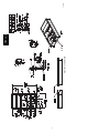
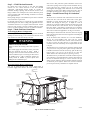
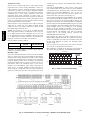
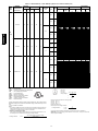
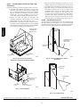
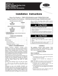
Fig. 1 -- Roof Curb Details
50PG03-- 07
C07269
3
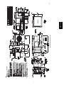
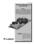
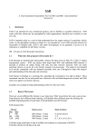
Fig. 2 -- Base Unit Dimensions
50PG03-- 07
C07271
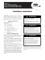
INSTALLATION
Positioning
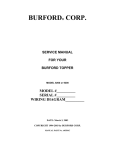
Maintain clearance, per Fig. 2, around and above unit to provide
minimum distance from combustible materials, proper airflow, and
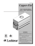
service access. See Fig. 4 for location of access panels.
Do not install unit in an indoor location. Do not locate air inlets
near exhaust vents or other sources of contaminated air.
Although unit is weatherproof, guard against water from higher
level runoff and overhangs.
After unit is in position, remove crating and polyethylene sheet.
Step 1 — Provide Unit Support
50PG03-- 07
Roof Curb
Assemble or install accessory roof curb in accordance with
instructions shipped with this accessory. (See Fig. 1.) Install
insulation, cant strips, roofing, and counter flashing as shown.
Ductwork can be installed to roof curb before unit is set in place.
Ductwork must be attached to curb and not to the unit. Curb must
be level. This is necessary to permit unit drain to function properly.
Unit leveling tolerance is 1/16--in. per linear ft in any direction.
Refer to Accessory Roof Curb Installation Instructions for
additional information as required. When accessory roof curb is
used, unit may be installed on class A, B, or C roof covering
material. Carrier roof curb accessories are for flat roofs or slab
mounting.
IMPORTANT: The gasketing of the unit to the roof curb is critical
for a watertight seal. Install gasket with the roof curb as shown in
Fig. 1. Improperly applied gasket can also result in air leaks and
poor unit performance. Do not slide unit to position on roof curb.
Roof Mount
Check building codes for weight distribution requirements. Unit
operating weight is shown in Table 1.
Installation Onto Curb
The 50PG units are designed to fit on the accessory full perimeter
curb. In either case, correct placement of the unit onto the curb is
critical to operating performance. To aid in correct positioning,
place unit on roof curb to maintain 1/4--in. gap between the inside
of rail and roof curb on long sides and a 1/2--in. gap between the
inside of rail and roof curb on both duct and condenser ends. Refer
to Fig. 1 and 3, to assure proper duct opening alignment.
NOTE: Before positioning unit onto curb, refer to Step 5 -- Install
External Trap for Condensate Drain section concerning bottom
drain connection plug.
Alternate Unit Support
When a curb cannot be used, install unit on a noncombustible
surface. Support unit with sleepers, using unit curb support area. If
sleepers cannot be used, support long sides of unit with a minimum
of 3 equally spaced 4--in. x 4--in. pads on each side.
!
Step 2 — Rig and Place Unit
Inspect unit for transportation damage. See Table 1 for physical
data. File any claim with transportation agency.
!
CAUTION
UNIT DAMAGE HAZARD
Failure to follow this caution may result in equipment
damage.
CAUTION
Do not slide unit to position when it is sitting on the curb.
Curb gasketing material may be damaged and leaks may
result.
PERSONAL INJURY AND PROPERTY DAMAGE HAZARD
Failure to follow this caution may result in damage to roof.
All panels must be in place when rigging. Unit is not
designed for handling by fork truck.
Slab Mount (Horizontal Units Only)
Provide a level concrete slab that extends a minimum of 6--in.
beyond unit cabinet. Install a gravel apron in front of
condenser--coil air inlet to prevent grass and foliage from
obstructing airflow.
NOTE: Horizontal units may be installed on a roof curb if
required.
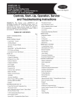
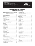
Do not drop unit; keep upright. Use spreader bars over unit to
prevent sling or cable damage. Rollers may be used to move unit
across a roof. Level by using unit rail as a reference; leveling
tolerance is ± 1/16--in. per linear ft in any direction. See Fig. 3 for
additional information. Unit rigging weight is shown in Fig. 3.
Rigging holes are provided in the unit base rails as shown in Fig. 3.
Refer to rigging instructions on unit.
CAUTION - NOTICE TO RIGGERS:
ACCESS PANEL MUST BE IN PLACE WHEN RIGGING.
Hook rigging shackles through holes in base rail, as shown in
Detail A. Holes in base rails are centered around the unit
center of gravity. Use wooden top skid, when rigging, to
prevent rigging straps from damaging unit.
UNIT
SIZE
03-07
A
in.
77.9
B
mm
1978
in.
36-54
C
mm
914-1371
in.
44.8
D
mm
1139
in.
42.0
E
mm
1067
in.
23.5
mm
597
MAX. WEIGHT
lb
kg
1156
525
C07270
Fig. 3 -- 50PG Rigging Label
4
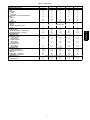
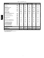
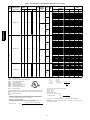
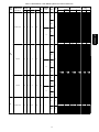
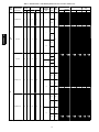
BASE UNIT 50PG
NOMINAL CAPACITY (Tons)
OPERATING WEIGHT (lb)
Unit*
Economizer
Vertical
Horizontal
Humidi-MiZer™ Adaptive Dehumidification
System
Roof Curb
14-in.
24-in.
COMPRESSOR
Quantity
Oil Type
Number of Refrigerant Circuits
Oil (oz)
REFRIGERANT TYPE
Expansion Device
Operating Charge (lb) — Standard Unit
Operating Charge (lb) — Unit with
Humidi-MiZer System
CONDENSER COIL
Condenser A (Outer)
Rows...Fins/in.
Face Area (sq ft)
Condenser B (Inner)
Rows...Fins/in.
Face Area (sq ft)
Humidi-MiZer Coil
Rows...Fins/in.
Face Area (sq ft)
CONDENSER FAN
Quantity…Diameter (in.)
Nominal Cfm (Total, all fans)
Motor Hp
Nominal Rpm — High Speed
Nominal Rpm — Low Speed
EVAPORATOR COIL
Rows…Fins/in.
Face Area (sq ft)
03
2
04
3
05
4
06
5
07
6
704
704
775
829
874
40
50
40
50
40
50
40
50
40
50
22
22
31
27
26
122
184
122
184
122
184
122
184
1
1
1
1
1
38
1
42
1
66
1
56
TXV
7.3
TXV
9.0
122
184
Fully Hermetic Scroll
1
Copeland 3MA
1
42
R-410A (Puron® Refrigerant)
TXV
15.7
TXV
16.6
TXV
19.0
13.50
25.00
22.00
22.70
11.75
Enhanced Copper Tubes, Aluminum Lanced Fins
1…17
12.6
1…17
12.6
2…17
12.6
2…17
12.6
2…17
12.6
—
—
1…17
12.6
2…17
12.6
2…17
12.6
2…17
12.6
1...17
6.4
1...17
6.4
1...17
1...17
9.3
9.3
Propeller
1…24
1…24
1…24
1…24
3500
3500
3500
4500
1/
1/
1/
1/
8
8
8
4
825
825
825
1100
300
300
300
300
Enhanced Copper Tubes, Aluminum Double-Wavy Fins, Face Split
2…15
2…15
2…15
3…15
9.3
9.3
9.3
9.3
* See Legend on next page.
5
1...17
9.3
1…24
4500
1/
4
1100
300
4…15
9.3
50PG03-- 07
Table 1 – Physical Data
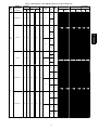
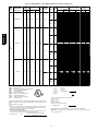
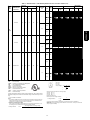
Table 1 — Physical Data (cont)
BASE UNIT 50PG (cont)
EVAPORATOR FAN
Quantity…Size (in.)
Type Drive
Nominal Cfm
Maximum Continuous Bhp
Motor Nominal Rpm
Motor Frame Size
Fan Rpm Range
Motor Bearing Type
Maximum Fan Rpm
Motor Pulley Pitch Diameter Range (in.)
50PG03-- 07
Fan Pulley Pitch Diameter (in.)
Nominal Motor Shaft Diameter (in.)
Belt...Pitch Length (in.)
Belt…Type
Pulley Center Line Distance Min. (in.)
Pulley Center Line Distance Max. (in.)
Speed Change per Full Turn of
Movable Pulley Flange (rpm)
Movable Pulley Maximum Full
Turns from Closed Position
Factory Pulley Setting (rpm)
Fan Shaft Diameter at Pulley (in.)
HIGH-PRESSURE SWITCH (psig)
Cutout
Reset (Auto.)
RETURN-AIR FILTERS
Quantity…Size (in.)
03
Low
High
Low
High
Low
High
Low
High
Low
High
Low
High
Low
High
Low
High
Low
High
Low
High
Low
High
Low
High
Low
High
Low
High
Low
High
04
1...12 x 9
1...12 x 9
Belt
Belt
800
0.85
0.85
1620
48Y
48Y
482-736
656-1001
Ball
2000
1.9-2.9
1.9-2.9
6.8
5.0
1/
2
1/
2
49.3
49.3
AX
AX
16.2
16.2
20.2
20.2
48
65
5
5
482
656
3/
4
05
06
Centrifugal Type, Belt Drive
1...12 x 9
1...12 x 9
1...12 x 9
1...12 x 9
1...12 x 9
1...12 x 9
Belt
Belt
Belt
Belt
Belt
Belt
1200
1600
2000
0.85
0.85
0.85/2.40†
0.85
1.60/2.40†
1.60/2.40†
1620
1620
1725
48Y
48Y
56Y
48Y
56Y
56Y
482-736
596-910
690-978
796-1128
828-1173
929-1261
Ball
Ball
Ball
2000
2000
2000
1.9-2.9
1.9-2.9
2.4-3.4
2.4-3.4
2.4-3.4
2.8-3.8
6.8
5.5
6.0
5.2
5.0
5.2
1/
1/
5/
2
2
8
1/
5/
5/
2
8
8
49.3
49.3
49.3
49.3
49.3
49.3
AX
AX
AX
AX
AX
AX
16.2
16.2
16.2
16.2
16.2
16.2
20.2
20.2
20.2
20.2
20.2
20.2
48
59
58
62
69
66
5
5
5
5
5
5
482
596
690
796
828
929
3/
3/
3/
4
4
4
660 ± 10
505 ± 20
660 ± 10
505 ± 20
4…16 x 20 x 2
4…16 x 20 x 2
LEGEND
TXV --- Thermostatic Expansion Valve
* Aluminum evaporator coil/aluminum condenser coil.
{ Single phase/three phase.
6
660 ± 10
505 ± 20
Throwaway
4…16 x 20 x 2
07
1...12 x 9
1...12 x 9
Belt
Belt
2400
2.40
3.10
1725
56Y
56Y
796-1128
1150-1438
Ball
2000
2.4-3.4
4.0-5.0
5.2
6.0
5/
8
7/
8
49.3
52.3
AX
AX
16.2
16.2
20.2
20.2
66
58
5
5
796
1150
3/
4
660 ± 10
505 ± 20
660 ± 10
505 ± 20
4…16 x 20 x 2
4…16 x 20 x 2
On vertical units, secure all ducts to roof curb and building
structure. Do not connect ductwork to unit. For horizontal
applications, field--supplied flanges should be attached to
horizontal discharge openings and all ductwork secured to the
flanges. Insulate and weatherproof all external ductwork, joints,
and roof openings with counter flashing and mastic in accordance
with applicable codes.
Ducts passing through an unconditioned space must be insulated
and covered with a vapor barrier.
If a plenum return is used on a vertical unit, the return should be
ducted through the roof deck to comply with applicable fire codes.
A minimum clearance is not required around ductwork. Cabinet
return--air static pressure (a negative condition) shall not exceed
0.35--in. wg with economizer or 0.45--in. wg without economizer.
Step 4 — Make Unit Duct Connections
Vertical Supply/Return Configuration
Unit is shipped in vertical supply/return configuration. Ductwork
openings are shown in Fig. 1 and 3. Attach the ductwork to the
roof curb. Do not attach duct directly to the unit.
!
WARNING
PERSONAL INJURY HAZARD
Failure to follow this warning could result in personal
injury.
For vertical supply and return units, tools or parts could
drop into ductwork and cause an injury. Install a
90--degree turn in the return ductwork between the unit
and the conditioned space. If a 90--degree elbow cannot
be installed, then a grille of sufficient strength and
density should be installed to prevent objects from
falling into the conditioned space.
Horizontal Supply/Return Applications
duct covers to duct panel. Save panels. Install duct covers in the
vertical duct openings in the basepan with the insulation side up.
Covers will drop into openings and can be secured using
field--supplied self--tapping screws. Ductwork can be attached to
duct flanges provided on unit. When securing ductwork to unit, do
not drill in area below bead or above top edge of duct opening.
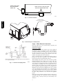
Step 5 — Install External Trap for Condensate
Drain
The unit’s 3/4--in. condensate drain connections are located on the
bottom and side of the unit. If the down drain is used, drill a
minimum of a 5/8-in. diameter hole but not larger than a 3/4-in.
diameter hole through the drain pan. A dimple of 2 mm in
diameter and 1.5 mm deep will be provided in the drain pan to help
locate the drill bit and to start the hole. Do not cut through the
PVC pipe threads. Unit discharge connections do not determine
the use of drain connections; either drain connection can be used
with vertical or horizontal applications. See Fig. 2 for locations.
When using the standard side drain connection, make sure the plug
(red) in the alternate bottom connection is tight before installing the
unit. (See Fig. 5.)
To use the bottom drain connection for a roof curb installation,
relocate the factory--installed plug (red) from the bottom
connection to the side connection. A 1/2--in. socket extension can
be used to remove the plug. (See Fig. 5.) The piping for the
condensate drain and external trap can be completed after the unit
is in place.
All units must have an external trap for condensate drainage. Install
a trap at least 4--in. deep and protect against freezeup. If drain line
is installed downstream from the external trap, pitch the line away
from the unit at 1--in. per 10 ft of run. Do not use a pipe size
smaller than the unit connection (3/4--in.). (See Fig. 6 and 7.)
The 50PG units are provided with a removable condensate pan for
ease of cleaning. It is recommended that a union be placed between
the unit and condensate drainage to ease the removal of the pan
during servicing. Adequate clearance should be allowed if removal
of condensate pan is required. Allow 54--in. between condensate
pan access panel and any obstruction for complete removal.
Unit can be field--converted from vertical supply/return to
horizontal supply/return. Remove all screws securing horizontal
CONTROL BOX
AND
COMPRESSOR
ELECTRICAL
OPTIONS PANEL
INDOOR MOTOR
ACCESS DOOR
OUTDOOR AIR
SCREEN
(HIDDEN)
CONDENSER COIL
ACCESS PANEL
ECONOMIZER
HOOD
BAROMETRIC
RELIEF DAMPER
HOOD
ELECTRIC HEAT
ACCESS DOOR
FILTER ACCESS DOOR
BASEPAN CONNECTIONS
ACCESS PANEL
C07272
Fig. 4 -- Panel and Filter Locations
7
50PG03-- 07
Step 3 — Field Fabricate Ductwork
INSERT SIDE DRAIN
PLUG FOR DOWN
DRAIN USE.
DRILL 5/8” DIA. (0.625 mm) HOLE
THRU FOR DOWN DRAIN USE.
C10321
Fig. 5 -- Condensate Drain Pan
50PG03-- 07
OPTIONAL UNIONS
TO ALLOW FOR CONDENSATE
PAN REMOVAL
4" (102mm)
CONDENSATE
PAN ACCESS
PANEL
C06234
Fig. 6 -- External Trap for Condensate Drain
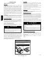
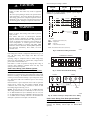
Step 6 — Make Electrical Connections
(For more details, refer to the Controls, Start--up, Operation, and
Troubleshooting manual).
Field Power Supply
NOTE: Trap should be deep enough to offset maximum unit static difference.
A 4-in. trap is recommended.
C06291
Fig. 7 -- Condensate Drain Piping Details
All 208/230--v units are factory wired for 230--v power supply. If
the 208/230--v unit is to be connected to a 208--v power supply, the
transformers (TRAN1 and TRAN2) must be rewired by moving
the black wire with the 1/4--in. female quick connect from the
230--volt connection and moving to the 200--volt 1/4--in. male
terminal on the primary side of the transformer.
Refer to unit label diagram for additional information. Leads are
provided for field wire connections. Use UL (Underwriters
Laboratories) approved copper/aluminum connector.
When installing rooftop units, provide safety disconnect per NEC
(National Electrical Code) Article 440 or local codes. For
non--fused disconnects, size the disconnect according to the sizing
data provided in the electrical data tables. If a fused disconnect is
used, determine the minimum size for the switch based on the
disconnect sizing data provided in the electrical data tables and
then coordinate the disconnect housing size to accommodate the
Maximum Overcurrent Protection (MOCP) device size as marked
on the unit informative plate. (See Table 2 and 3.) All field wiring
must comply with NEC and local codes. Size wire based on MCA
(Minimum Circuit Amps) on the unit informative plate. See Fig. 8
for power wiring connection to the unit leads and equipment
ground.
Route power and ground lines through control box end panel or
unit basepan (see Fig. 2) to connections as shown on unit wiring
diagram and Fig. 8. Factory leads may be wired directly to the
disconnect.
8
!
CAUTION
Set heat anticipator settings as follows:
VOLTAGE
Stage 1
(W1) ON
STAGE 1 AND 2
(W1 AND W2) ON
All
0.2
0.4
UNIT DAMAGE HAZARD
The correct power phasing is critical to the operation of the
scroll compressors. An incorrect phasing will result in an
alarm being generated and compressor operation lockout.
Should this occur, power phase correction must be made to
the incoming power. Damage to compressor could result.
!
Settings may be changed slightly to provide a greater degree of
comfort for a particular installation.
C.A1
DISCONNECT
PER NEC
Failure to follow this caution may result in equipment
damage.
WARNING
FIELD
FACTOR
POWER
POWER
WIRING
WIRING
11
21
12
22
13
23
Failure to follow this warning could result in personal
injury or death.
50PG03-- 07
ELECTRICAL SHOCK HAZARD
EQUIP GND
Unit cabinet must have an uninterrupted, unbroken
electrical ground to minimize the possibility of personal
injury if an electrical fault should occur. This ground may
consist of electrical wire connected to unit ground lug in
control compartment, or conduit approved for electrical
ground when installed in accordance with NEC; ANSI
(American National Standards Institute)/NFPA (National
Fire Protection Association), latest edition, and local
electrical codes.
LEGEND
C.A1
EQUIP
GND
NEC
-- Compressor Contactor (A1)
-- Equipment
-- Ground
-- National Electrical Code
NOTE: The maximum wire size for C.A1 is 2/0.
C06237
Fig. 8 -- Field Power Wiring Connections
Field wiring must conform to temperature limitations for type “T”
wire. All field wiring must comply with NEC and local
requirements.
Operating voltage to compressor must be within voltage range
indicated on unit nameplate. On 3--phase units, voltages between
phases must be balanced within 2%.
Unit failure as a result of operation on improper line voltage or
excessive phase imbalance constitutes abuse and may cause
damage to electrical components.
THERMOSTAT ASSEMB Y
REMOVABLE JUMPER
RH
TB1
R
Y1
Y2
W1
W2
G
C
Y1
Y2
W1
W2
G
C
L
X
X
ROOFTOP UNIT
Field Control Wiring (Units Without Optional
Humidi-- MiZert Adaptive Dehumidification System)
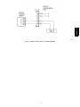
C06292
Fig. 9 -- Field Control Thermostat Wiring
T-56 SPT
T-55 SPT
SEN
SEN
SET
T55
TB1
BLACK
RED
RED
Unit can be controlled with either a Carrier--approved accessory
thermostat or a Carrier--approved space temperature sensor. Install
thermostat according to the installation instructions included with
accessory. Locate thermostat assembly or space temperature sensor
on a solid interior wall in the conditioned space to sense average
temperature.
Route thermostat or space temperature sensor cable or equivalent
single leads of colored wire from subbase terminals through
conduit into unit to low--voltage connections as shown on unit
label wiring diagram and in Fig. 9 or 10.
NOTE: For wire runs up to 50 ft, use no. 18 AWG (American
Wire Gauge) insulated wire (35_C minimum). For 50 to 75 ft, use
no. 16 AWG insulated wire (35_C minimum). For over 75 ft, use
no. 14 AWG insulated wire (35_C Minimum). All wire larger than
no. 18 AWG cannot be directly connected at the thermostat and
will require a junction box and splice at the thermostat.
RC
BLACK
WHITE
JUMPER
1
2
3
ROOFTOP UNIT
C06239
Fig. 10 -- Field Control Space Temperature Sensor Wiring
Field Control Wiring (Units With Optional Humidi-MiZert Adaptive Dehumidification System)
Units require temperature control inputs for cooling and heating
operation and humidity control inputs for Humidi--MiZer
operation.
9
50PG03-- 07
Temperature Control
The unit can be controlled with either a Carrier--approved space
temperature sensor, a Carrier accessory Thermidistatt device, or a
Carrier--approved accessory thermostat. Install the temperature
control device according to the installation instructions included
with the accessory. Locate the device on a solid interior wall in the
conditioned space to sense average temperature. Carrier space
temperature sensor wiring connections are shown in Fig. 10.
General thermostat field control wiring connections are shown in
Fig. 9. Carrier Thermidistat device wiring connections are shown
in Fig. 11. Configuration of the unit control is required to specify
the control input type before unit operation.
Route thermostat or space temperature sensor cable or equivalent
single leads of colored wire from subbase terminals through
conduit into unit to low--voltage connections as shown on unit
label wiring diagram and in Fig. 9--11.
NOTE: For wire runs up to 50 ft, use no. 18 AWG (American
Wire Gauge) insulated wire (35_C minimum). For 50 to 75 ft, use
no. 16 AWG insulated wire (35_C minimum). For over 75 ft, use
no. 14 AWG insulated wire (35_C Minimum). All wire larger than
no. 18 AWG cannot be directly connected at the thermostat and
will require a junction box and splice at the thermostat.
Set heat anticipator settings as follows:
VOLTAGE
Stage 1
(W1) ON
STAGE 1 AND 2
(W1 AND W2) ON
All
0.2
0.4
Settingsmay be changed slightly to provide a greater degree of
comfort for a particular installation.
Humidity Control
Unit can be controlled with either a Carrier accessory Thermidistat
device or a Carrier--approved accessory humidistat (switch output).
The input for an accessory humidity sensor with 4 to 20 mA output
is another option available when an economizer board is installed.
Install the humidity control device according to the installation
instructions included with the accessory. Locate the device on a
solid interior wall in the conditioned space to sense average
humidity. Carrier Thermidistat device wiring connections are
shown in Fig. 11. General humidistat wiring connections are
shown in Fig. 12. Configuration of the unit control is required to
specify the control input type before unit operation. Refer to the
Controls, Start--up, Operation and Troubleshooting manual for
configuration.
Units with the Humidi--MiZert option receive a discrete input
from a field--installed device (such as from the Carrier humidistat
or Thermidistat device). The discrete input is connected to the TB1
terminal strip points labeled Humidistat 1 and 2. As this is a
discrete input, one of the connection points is for power to the
switch and the other is the return path. (See Fig. 12.)
A space relative humidity sensor input (SP.RH) is only available if
an economizer board (ECB) is installed in the unit and then the
sensor can be connected to the OAQ point TB1--4. (See Fig. 12.)
This input is used instead of the discrete humidistat or thermidistat
inputs. The input controls the Humidi--MiZer using the 4 to 20 mA
as percent humidity. The relative humidity value (measured by the
relative humidity sensor) can be displayed on the Scrolling
Marquee, in the space through a System Pilott device, or can be
read by other CCN devices where it can be used to perform more
advanced functions. The humidity sensor must be configured
correctly; refer to the Controls, Start--up, Operation, and
Troubleshooting manual for details.
If the customer also wishes to install a smoke detector into a
Humidi--MiZer equipped 50PG unit, the fire shutdown connection
points are on Plug PL--19, located in the economizer section. See
the unit wiring schematic for wiring. For third--party smoke
detector, see Fig. 13.
Point 19--3 is the 24 vac power source for the detector and point
19--5 is the 24 vac signal input for fire shutdown.
More information is available in the third party control section of
the Controls, Start--up, Operation, and Troubleshooting manual.
THERMIDISTAT
TB1
OC
R
Y1
Y2
W1
W2
G
C
5
R
Y1
Y2
W1
W2
G
C
DEHUM
1
2
HUMIDISTAT
ROOFTOP UNIT
C07055
Fig. 11 -- Field Control Thermidistat Wiring
C07045
Fig. 12 -- Humidi--MiZer Low--Voltage Terminal Strip -- Humidity Sensor/Humidity Wiring
10
50PG03-- 07
C07191
Fig. 13 -- Third Party Smoke Detector on Humidi--MiZert
11
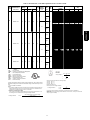
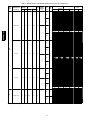
Table 2 – Electrical Data -- Units Without Optional Convenience Outlet
NOMINAL
UNIT POWER SUPPLY
50PG
Volts-Ph-Hz
VOLTAGE
RANGE
Min
Max
COMPRESSOR
RLA
LRA
OFM
FLA
POWER
EXHAUST
FLA
IFM
TYPE
IFM
FLA
Low
—
High
03
208/230-1-60
187
253
12.8
60
1.0
4.9
Low
1.4
50PG03-- 07
High
Low
—High
208/230-1-60
187
253
15.4
83
1.0
4.9
Low
04
1.4
High
Low
208/230-3-60
187
253
11.5
77
1.0
—
4.9
High
FLA
HACR
IFM
LRA
MCA
MOCP
NEC
OFM
RLA
-------------------
LEGEND
Full Load Amps
Heating, Air Conditioning and Refrigeration
Indoor (Evaporator) Fan Motor
Locked Rotor Amps
Minimum Circuit Amps
Maximum Overcurrent Protection
National Electrical Code
Outdoor (Condenser) Fan Motor
Rated Load Amps
*Heater capacity (kW) is based on heater voltage of 208v, 240v, 480v, or 600v. If power
distribution voltage to unit varies from rated heater voltage, heater kW will vary accordingly.
{ Fuse or HACR circuit breaker.
NOTES:
1. In compliance with NEC requirements for multimotor and combination load equipment (refer
to NEC Articles 430 and 440), the overcurrent protective device for the unit shall be fuse or
HACR breaker. Canadian units may be fuse or circuit breaker.
2. Unbalanced 3-Phase Supply Voltage
Never operate a motor where a phase imbalance in supply voltage is greater than 2%. Use
the following formula to determine the percentage of voltage imbalance.
% Voltage Imbalance
= 100 x
ELECTRIC HEAT
FLA
—
10.8/12.5
17.3/20.0
26.0/30.0
34.7/40.0
—
10.8/12.5
17.3/20.0
26.0/30.0
34.7/40.0
—
10.8/12.5
17.3/20.0
26.0/30.0
34.7/40.0
—
10.8/12.5
17.3/20.0
26.0/30.0
34.7/40.0
—
10.8/12.5
17.3/20.0
26.0/30.0
34.7/40.0
52.0/60.0
—
10.8/12.5
17.3/20.0
26.0/30.0
34.7/40.0
52.0/60.0
—
10.8/12.5
17.3/20.0
26.0/30.0
34.7/40.0
52.0/60.0
—
10.8/12.5
17.3/20.0
26.0/30.0
34.7/40.0
52.0/60.0
—
6.3/ 7.2
10.0/11.5
15.0/17.3
20.0/23.1
30.0/34.6
—
6.3/ 7.2
10.0/11.5
15.0/17.3
20.0/23.1
30.0/34.6
POWER SUPPLY
Nominal
kW*
—
2.3/ 3.0
3.8/ 5.0
5.6/ 7.5
7.5/10.0
—
2.3/ 3.0
3.8/ 5.0
5.6/ 7.5
7.5/10.0
—
2.3/ 3.0
3.8/ 5.0
5.6/ 7.5
7.5/10.0
—
2.3/ 3.0
3.8/ 5.0
5.6/ 7.5
7.5/10.0
—
2.3/ 3.0
3.8/ 5.0
5.6/ 7.5
7.5/10.0
11.3/15.0
—
2.3/ 3.0
3.8/ 5.0
5.6/ 7.5
7.5/10.0
11.3/15.0
—
2.3/ 3.0
3.8/ 5.0
5.6/ 7.5
7.5/10.0
11.3/15.0
—
2.3/ 3.0
3.8/ 5.0
5.6/ 7.5
7.5/10.0
11.3/15.0
—
2.3/ 3.0
3.8/ 5.0
5.6/ 7.5
7.5/10.0
11.3/15.0
—
2.3/ 3.0
3.8/ 5.0
5.6/ 7.5
7.5/10.0
11.3/15.0
DISCONNECT
SIZE
MCA
MOCP†
FLA
LRA
21.9/21.9
21.9/21.9
27.8/31.1
38.6/43.6
49.5/56.1
21.9/21.9
21.9/21.9
27.8/31.1
38.6/43.6
49.5/56.1
23.3/23.3
23.3/23.5
29.5/32.9
40.4/45.4
51.3/57.9
23.3/23.3
23.3/23.5
29.5/32.9
40.4/45.4
51.3/57.9
25.2/25.2
25.2/25.2
27.8/31.1
38.6/43.6
49.5/56.1
71.1/81.1
25.2/25.2
25.2/25.2
27.8/31.1
38.6/43.6
49.5/56.1
71.1/81.1
26.6/26.6
26.6/26.6
29.5/32.9
40.4/45.4
51.3/57.9
72.9/82.9
26.6/26.6
26.6/26.6
29.5/32.9
40.4/45.4
51.3/57.9
72.9/82.9
20.3/20.3
20.3/20.3
20.3/20.5
24.9/27.8
31.1/35.0
43.6/49.4
20.3/20.3
20.3/20.3
20.3/20.5
24.9/27.8
31.1/35.0
43.6/49.4
25/25
25/25
30/35
40/45
50/60
25/25
25/25
30/35
40/45
50/60
25/25
25/25
30/35
45/50
60/60
25/25
25/25
30/35
45/50
60/60
30/30
30/30
30/35
40/45
50/60
80/90
30/30
30/30
30/35
40/45
50/60
80/90
30/30
30/30
30/35
45/50
60/60
80/90
30/30
30/30
30/35
45/50
60/60
80/90
25/25
25/25
25/25
25/30
35/40
45/50
25/25
25/25
25/25
25/30
35/40
45/50
22/22
22/22
26/29
36/40
46/52
22/22
22/22
26/29
36/40
46/52
23/23
23/23
27/30
37/42
47/53
23/23
23/23
27/30
37/42
47/53
24/24
24/24
26/29
36/40
46/52
65/75
24/24
24/24
26/29
36/40
46/52
65/75
26/26
26/26
27/30
37/42
47/53
67/76
26/26
26/26
27/30
37/42
47/53
67/76
20/20
20/20
20/20
23/26
29/32
40/45
20/20
20/20
20/20
23/26
29/32
40/45
74/74
74/74
74/74
74/74
74/74
74/74
74/74
74/74
74/74
74/74
76/76
76/76
76/76
76/76
76/76
76/76
76/76
76/76
76/76
76/76
97/97
97/97
97/97
97/97
97/97
97/97
97/97
97/97
97/97
97/97
97/97
97/97
99/99
99/99
99/99
99/99
99/99
99/99
99/99
99/99
99/99
99/99
99/99
99/99
91/91
91/91
91/91
91/91
91/91
91/91
91/91
91/91
91/91
91/91
91/91
91/91
Example: Supply voltage is 230 ---3 ---60
AB = 224 v
BC = 231 v
AC = 226 v
Average Voltage =
224 + 231 + 226
3
=
681
3
=
227
Determine maximum deviation from average voltage.
(AB) 227 – 224 = 3 v
(BC) 231 – 227 = 4 v
(AC) 227 – 226 = 1 v
Maximum deviation is 4 v.
Determine percent of voltage imbalance.
% Voltage Imbalance
= 100 x
= 1.76%
4
227
This amount of phase imbalance is satisfactory as it is below the maximum allowable 2%.
IMPORTANT: If the supply voltage phase imbalance is more than 2%, contact your local electric
utility company immediately.
max voltage deviation from average voltage
average voltage
12
Table 2 -- Electrical Data -- Units Without Optional Convenience Outlet (cont)
NOMINAL
POWER SUPPLY
Volts-Ph-Hz
VOLTAGE
RANGE
Min
Max
COMPRESSOR
RLA
LRA
OFM
FLA
POWER
EXHAUST
FLA
IFM
TYPE
IFM
FLA
Low
208/230-3-60
187
253
11.5
77
1.0
1.4
4.9
High
Low
—
High
04
(cont)
460-3-60
414
506
5.1
35
0.5
2.1
Low
0.6
High
Low
—
High
575-3-60
518
633
4.3
31
0.5
2.1
Low
1.4
High
Low
4.9
High
7.0
Low
4.9
High
7.0
Low
4.9
High
5.2
Low
4.9
High
5.2
—
208/230-1-60
187
253
20.5
109
1.0
1.4
05
—
208/230-3-60
187
253
14.6
91
1.0
*See Legend on next page.
13
ELECTRIC HEAT
FLA
—
6.3/ 7.2
10.0/11.5
15.0/17.3
20.0/23.1
30.0/34.6
—
6.3/ 7.2
10.0/11.5
15.0/17.3
20.0/23.1
30.0/34.6
—
3.5
5.8
8.7
11.5
17.3
—
3.5
5.8
8.7
11.5
17.3
—
3.5
5.8
8.7
11.5
17.3
—
3.5
5.8
8.7
11.5
17.3
—
9.2
13.9
—
9.2
13.9
—
9.2
13.9
—
9.2
13.9
—
17.3/20.0
26.0/30.0
34.7/40.0
52.0/60.0
69.3/80.0
—
17.3/20.0
26.0/30.0
34.7/40.0
52.0/60.0
69.3/80.0
—
17.3/20.0
26.0/30.0
34.7/40.0
52.0/60.0
69.3/80.0
—
17.3/20.0
26.0/30.0
34.7/40.0
52.0/60.0
69.3/80.0
—
10.0/11.5
15.0/17.3
20.0/23.1
30.0/34.6
40.0/46.2
—
10.0/11.5
15.0/17.3
20.0/23.1
30.0/34.6
40.0/46.2
—
10.0/11.5
15.0/17.3
20.0/23.1
30.0/34.6
40.0/46.2
—
10.0/11.5
15.0/17.3
20.0/23.1
30.0/34.6
40.0/46.2
Nominal
kW*
—
2.3/ 3.0
3.8/ 5.0
5.6/ 7.5
7.5/10.0
11.3/15.0
—
2.3/ 3.0
3.8/ 5.0
5.6/ 7.5
7.5/10.0
11.3/15.0
—
3.0
5.0
7.5
10.0
15.0
—
3.0
5.0
7.5
10.0
15.0
—
3.0
5.0
7.5
10.0
15.0
—
3.0
5.0
7.5
10.0
15.0
—
10.0
15.0
—
10.0
15.0
—
10.0
15.0
—
10.0
15.0
—
3.8/ 5.0
5.6/ 7.5
7.5/10.0
11.3/15.0
15.0/20.0
—
3.8/ 5.0
5.6/ 7.5
7.5/10.0
11.3/15.0
15.0/20.0
—
3.8/ 5.0
5.6/ 7.5
7.5/10.0
11.3/15.0
15.0/20.0
—
3.8/ 5.0
5.6/ 7.5
7.5/10.0
11.3/15.0
15.0/20.0
—
3.8/ 5.0
5.6/ 7.5
7.5/10.0
11.3/15.0
15.0/20.0
—
3.8/ 5.0
5.6/ 7.5
7.5/10.0
11.3/15.0
15.0/20.0
—
3.8/ 5.0
5.6/ 7.5
7.5/10.0
11.3/15.0
15.0/20.0
—
3.8/ 5.0
5.6/ 7.5
7.5/10.0
11.3/15.0
15.0/20.0
POWER SUPPLY
DISCONNECT
SIZE
MCA
MOCP†
FLA
LRA
21.7/21.7
21.7/21.7
21.7/22.3
26.6/29.5
32.9/36.8
45.4/51.1
21.7/21.7
21.7/21.7
21.7/22.3
26.6/29.5
32.9/36.8
45.4/51.1
9.0
9.0
9.9
13.5
17.0
24.3
9.0
9.0
9.9
13.5
17.0
24.3
9.6
9.6
10.6
14.3
17.8
25.0
9.6
9.6
10.6
14.3
17.8
25.0
8.0
14.1
20.0
8.0
14.1
20.0
9.4
15.9
21.8
9.4
15.9
21.8
31.5/ 31.5
31.5/ 31.5
38.6/ 43.6
49.5/ 56.1
71.1/ 81.1
92.8/106.1
33.6/ 33.6
33.6/ 33.8
41.3/ 46.3
52.1/ 58.8
73.8/ 83.8
95.4/108.8
32.9/ 32.9
32.9/ 32.9
40.4/ 45.4
51.3/ 57.9
72.9/ 82.9
94.5/107.9
35.0/ 35.5
35.0/ 35.5
43.0/ 48.0
53.9/ 60.5
75.5/ 85.5
97.1/110.5
24.2/24.2
24.2/24.2
24.9/27.8
31.1/35.0
43.6/49.4
56.1/63.9
24.5/24.5
24.5/24.5
25.3/28.1
31.5/35.4
44.0/49.8
56.5/64.3
25.6/25.6
25.6/25.6
26.6/29.5
32.9/36.8
45.4/51.1
57.9/65.6
25.9/25.9
25.9/25.9
27.0/29.9
33.3/37.1
45.8/51.5
58.3/66.0
25/25
25/25
25/25
30/30
35/40
50/60
25/25
25/25
25/25
30/30
35/40
50/60
15
15
15
15
20
25
15
15
15
15
20
25
15
15
15
15
20
30
15
15
15
15
20
30
15
15
25
15
15
25
15
20
25
15
20
25
35/ 35
35/ 35
40/ 45
50/ 60
80/ 90
100/110
35/ 35
35/ 35
45/ 50
60/ 60
80/ 90
100/110
35/ 35
35/ 35
45/ 50
60/ 60
80/ 90
100/110
40/ 40
40/ 40
45/ 50
60/ 70
80/ 90
100/125
25/25
25/25
25/30
35/40
45/50
60/70
25/25
25/25
30/30
35/40
45/50
60/70
30/30
30/30
30/30
35/40
50/60
60/70
30/30
30/30
30/30
35/40
50/60
60/70
22/22
22/22
22/22
24/27
30/34
42/47
22/22
22/22
22/22
24/27
30/34
42/47
9
9
9
12
16
22
9
9
9
12
16
22
10
10
10
13
16
23
10
10
10
13
16
23
8
13
18
8
13
18
10
15
20
10
15
20
30/30
30/30
36/40
46/52
65/75
85/98
33/ 33
33/ 33
38/ 43
48/ 54
68/ 77
88/100
32/32
32/32
37/42
47/53
67/76
87/99
34/ 34
34/ 34
40/ 44
50/ 56
69/ 79
89/102
24/24
24/24
24/26
29/32
40/45
52/59
24/24
24/24
24/26
29/33
40/46
52/59
25/25
25/25
25/27
30/34
42/47
53/60
26/26
26/26
26/27
31/34
42/47
54/61
93/93
93/93
93/93
93/93
93/93
93/93
93/93
93/93
93/93
93/93
93/93
93/93
42
42
42
42
42
42
42
42
42
42
42
42
43
43
43
43
43
43
43
43
43
43
43
43
37
37
37
37
37
37
39
39
39
39
39
39
123/123
123/123
123/123
123/123
123/123
123/123
148/148
148/148
148/148
148/148
148/148
148/148
125/125
125/125
125/125
125/125
125/125
125/125
150/150
150/150
150/150
150/150
150/150
150/150
105/105
105/105
105/105
105/105
105/105
105/105
123/123
123/123
123/123
123/123
123/123
123/123
107/107
107/107
107/107
107/107
107/107
107/107
125/125
125/125
125/125
125/125
125/125
125/125
50PG03-- 07
UNIT
50PG
Table 2 -- Electrical Data -- Units Without Optional Convenience Outlet (cont)
UNIT
50PG
NOMINAL
POWER SUPPLY
Volts-Ph-Hz
VOLTAGE
RANGE
Min
Max
COMPRESSOR
RLA
LRA
OFM
FLA
POWER
EXHAUST
FLA
IFM
TYPE
IFM
FLA
Low
2.1
High
2.6
Low
2.1
High
2.6
Low
2.1
High
2.0
Low
2.1
High
2.0
Low
4.9
High
7.0
Low
4.9
High
7.0
—
460-3-60
414
506
7.1
46
0.5
50PG03-- 07
0.6
05
(cont)
—
575-3-60
518
633
5.1
34
0.5
1.4
—
06
208/230-1-60
187
253
26.9
145
1.5
1.4
FLA
HACR
IFM
LRA
MCA
MOCP
NEC
OFM
RLA
-------------------
LEGEND
Full Load Amps
Heating, Air Conditioning and Refrigeration
Indoor (Evaporator) Fan Motor
Locked Rotor Amps
Minimum Circuit Amps
Maximum Overcurrent Protection
National Electrical Code
Outdoor (Condenser) Fan Motor
Rated Load Amps
*Heater capacity (kW) is based on heater voltage of 208v, 240v, 480v, or 600v. If power
distribution voltage to unit varies from rated heater voltage, heater kW will vary accordingly.
{ Fuse or HACR circuit breaker.
NOTES:
1. In compliance with NEC requirements for multimotor and combination load equipment (refer
to NEC Articles 430 and 440), the overcurrent protective device for the unit shall be fuse or
HACR breaker. Canadian units may be fuse or circuit breaker.
2. Unbalanced 3-Phase Supply Voltage
Never operate a motor where a phase imbalance in supply voltage is greater than 2%. Use
the following formula to determine the percentage of voltage imbalance.
% Voltage Imbalance
= 100 x
ELECTRIC HEAT
FLA
—
5.8
8.7
11.5
17.3
23.1
—
5.8
8.7
11.5
17.3
23.1
—
5.8
8.7
11.5
17.3
23.1
—
5.8
8.7
11.5
17.3
23.1
—
9.2
13.9
18.5
—
9.2
13.9
18.5
—
9.2
13.9
18.5
—
9.2
13.9
18.5
—
17.3/ 20.0
26.0/ 30.0
34.7/ 40.0
52.0/ 60.0
69.3/ 80.0
86.7/100.0
—
17.3/ 20.0
26.0/ 30.0
34.7/ 40.0
52.0/ 60.0
69.3/ 80.0
86.7/100.0
—
17.3/ 20.0
26.0/ 30.0
34.7/ 40.0
52.0/ 60.0
69.3/ 80.0
86.7/100.0
—
17.3/ 20.0
26.0/ 30.0
34.7/ 40.0
52.0/ 60.0
69.3/ 80.0
86.7/100.0
POWER SUPPLY
Nominal
kW*
—
5.0
7.5
10.0
15.0
20.0
—
5.0
7.5
10.0
15.0
20.0
—
5.0
7.5
10.0
15.0
20.0
—
5.0
7.5
10.0
15.0
20.0
—
10.0
15.0
20.0
—
10.0
15.0
20.0
—
10.0
15.0
20.0
—
10.0
15.0
20.0
—
3.8/ 5.0
5.6/ 7.5
7.5/10.0
11.3/15.0
15.0/20.0
18.8/25.0
—
3.8/ 5.0
5.6/ 7.5
7.5/10.0
11.3/15.0
15.0/20.0
18.8/25.0
—
3.8/ 5.0
5.6/ 7.5
7.5/10.0
11.3/15.0
15.0/20.0
18.8/25.0
—
3.8/ 5.0
5.6/ 7.5
7.5/10.0
11.3/15.0
15.0/20.0
18.8/25.0
Example: Supply voltage is 230 ---3 ---60
AB = 224 v
BC = 231 v
AC = 226 v
Average Voltage =
DISCONNECT
SIZE
MCA
MOCP†
FLA
LRA
11.5
11.5
13.5
17.0
24.3
31.5
12.0
12.0
14.1
17.6
24.9
32.1
12.1
12.1
14.3
17.8
25.0
32.3
12.6
12.6
14.9
18.4
25.6
32.9
9.0
14.1
20.0
25.8
8.9
14.0
19.9
25.6
10.4
15.9
21.8
27.5
10.3
15.8
21.6
27.4
40.0/ 40.0
40.0/ 40.0
40.0/ 43.6
49.5/ 56.1
71.1/ 81.1
92.8/106.1
114.5/131.1
42.1/ 42.1
42.1/ 42.1
42.1/ 46.3
52.1/ 58.8
73.8/ 83.8
95.4/108.8
117.1/133.8
41.4/ 41.4
41.4/ 41.4
41.4/ 45.4
51.3/ 57.9
72.9/ 82.9
94.5/107.9
116.3/132.9
43.5/ 43.5
43.5/ 43.5
43.5/ 48.0
53.9/ 60.5
75.5/ 85.5
97.1/110.5
118.9/135.5
15
15
15
20
25
35
15
15
15
20
25
35
15
15
15
20
30
35
15
15
15
20
30
35
15
15
25
30
15
15
20
30
15
20
25
30
15
20
25
30
45/ 45
45/ 45
45/ 45
50/ 60
80/ 90
100/110
125/150
45/ 45
45/ 45
45/ 50
60/ 60
80/ 90
100/110
125/150
45/ 45
45/ 45
45/ 50
60/ 60
80/ 90
100/110
125/150
50/ 50
50/ 50
50/ 50
60/ 70
80/ 90
100/125
125/150
11
11
12
16
22
29
12
12
13
16
23
30
12
12
13
16
23
30
12
12
14
17
24
30
9
13
18
24
9
13
18
24
10
15
20
25
10
14
20
25
38/38
38/38
38/40
46/52
65/75
85/98
105/121
41/41
41/41
41/43
48/54
68/77
88/100
108/123
40/40
40/40
40/42
47/53
67/76
87/99
107/122
42/42
42/42
42/44
50/56
69/79
89/102
109/125
53
53
53
53
53
53
62
62
62
62
62
62
54
54
54
54
54
54
63
63
63
63
63
63
40
40
40
40
46
46
46
46
42
42
42
42
48
48
48
48
160/160
160/160
160/160
160/160
160/160
160/160
160/160
185/185
185/185
185/185
185/185
185/185
185/185
185/185
162/162
162/162
162/162
162/162
162/162
162/162
162/162
187/187
187/187
187/187
187/187
187/187
187/187
187/187
224 + 231 + 226
3
=
681
3
=
227
Determine maximum deviation from average voltage.
(AB) 227 – 224 = 3 v
(BC) 231 – 227 = 4 v
(AC) 227 – 226 = 1 v
Maximum deviation is 4 v.
Determine percent of voltage imbalance.
% Voltage Imbalance
= 100 x
= 1.76%
4
227
This amount of phase imbalance is satisfactory as it is below the maximum allowable 2%.
IMPORTANT: If the supply voltage phase imbalance is more than 2%, contact your local electric
utility company immediately.
max voltage deviation from average voltage
average voltage
14
Table 2 -- Electrical Data -- Units Without Optional Convenience Outlet (cont)
NOMINAL
POWER SUPPLY
Volts-Ph-Hz
VOLTAGE
RANGE
Min
Max
COMPRESSOR
RLA
LRA
OFM
FLA
POWER
EXHAUST
FLA
IFM
TYPE
IFM
FLA
Low
—
High
208/230-3-60
187
253
17.6
123
1.5
5.2
Low
1.4
High
Low
—
06
(cont)
High
460-3-60
414
506
7.7
50
0.8
2.6
Low
0.6
High
Low
—
High
575-3-60
518
633
6.1
40
0.8
2.0
Low
1.4
High
07
208/230-3-60
187
253
20.5
149
1.5
Low
5.2
High
7.5
—
* See Legend on next page.
15
ELECTRIC HEAT
FLA
—
10.0/11.5
15.0/17.3
20.0/23.1
30.0/34.6
40.0/46.2
50.0/57.7
—
10.0/11.5
15.0/17.3
20.0/23.1
30.0/34.6
40.0/46.2
50.0/57.7
—
10.0/11.5
15.0/17.3
20.0/23.1
30.0/34.6
40.0/46.2
50.0/57.7
—
10.0/11.5
15.0/17.3
20.0/23.1
30.0/34.6
40.0/46.2
50.0/57.7
—
5.8
8.7
11.5
17.3
23.1
28.9
—
5.8
8.7
11.5
17.3
23.1
28.9
—
5.8
8.7
11.5
17.3
23.1
28.9
—
5.8
8.7
11.5
17.3
23.1
28.9
—
9.2
13.9
18.5
23.1
—
9.2
13.9
18.5
23.1
—
9.2
13.9
18.5
23.1
—
9.2
13.9
18.5
23.1
—
10.0/11.5
15.0/17.3
20.0/23.1
30.0/34.6
40.0/46.2
50.0/57.7
—
10.0/11.5
15.0/17.3
20.0/23.1
30.0/34.6
40.0/46.2
50.0/57.7
Nominal
kW*
—
3.8/ 5.0
5.6/ 7.5
7.5/10.0
11.3/15.0
15.0/20.0
18.8/25.0
—
3.8/ 5.0
5.6/ 7.5
7.5/10.0
11.3/15.0
15.0/20.0
18.8/25.0
—
3.8/ 5.0
5.6/ 7.5
7.5/10.0
11.3/15.0
15.0/20.0
18.8/25.0
—
3.8/ 5.0
5.6/ 7.5
7.5/10.0
11.3/15.0
15.0/20.0
18.8/25.0
—
5.0
7.5
10.0
15.0
20.0
25.0
—
5.0
7.5
10.0
15.0
20.0
25.0
—
5.0
7.5
10.0
15.0
20.0
25.0
—
5.0
7.5
10.0
15.0
20.0
25.0
—
10.0
15.0
20.0
25.0
—
10.0
15.0
20.0
25.0
—
10.0
15.0
20.0
25.0
—
10.0
15.0
20.0
25.0
—
3.8/ 5.0
5.6/ 7.5
7.5/10.0
11.3/15.0
15.0/20.0
18.8/25.0
—
3.8/ 5.0
5.6/ 7.5
7.5/10.0
11.3/15.0
15.0/20.0
18.8/25.0
POWER SUPPLY
DISCONNECT
SIZE
MCA
MOCP†
FLA
LRA
28.7/28.7
28.7/28.7
28.7/28.7
31.5/35.4
44.0/49.8
56.5/64.3
69.0/78.6
28.7/28.7
28.7/28.7
28.7/28.7
31.5/35.4
44.0/49.8
56.5/64.3
69.0/78.6
30.1/30.1
30.1/30.1
30.1/30.1
33.3/37.1
45.8/51.5
58.3/66.0
70.8/80.4
30.1/30.1
30.1/30.1
30.1/30.1
33.3/37.1
45.8/51.5
58.3/66.0
70.8/80.4
13.0
13.0
14.1
17.6
24.9
32.1
39.4
13.0
13.0
14.1
17.6
24.9
32.1
39.4
13.6
13.6
14.9
18.4
25.6
32.9
40.1
13.6
13.6
14.9
18.4
25.6
32.9
40.1
10.4
14.0
19.9
25.6
31.4
10.4
14.0
19.9
25.6
31.4
11.8
15.8
21.6
27.4
33.1
11.8
15.8
21.6
27.4
33.1
32.3/32.3
32.3/32.3
32.3/32.3
32.3/35.4
44.0/49.8
56.5/64.3
69.0/78.6
34.6/34.6
34.6/34.6
34.6/34.6
34.6/38.3
46.9/52.6
59.4/67.1
71.9/81.5
30/30
30/30
30/30
35/40
45/50
60/70
70/80
30/30
30/30
30/30
35/40
45/50
60/70
70/80
35/35
35/35
35/35
35/40
50/60
60/70
80/90
35/35
35/35
35/35
35/40
50/60
60/70
80/90
15
15
15
20
25
35
40
15
15
15
20
25
35
40
15
15
15
20
30
35
45
15
15
15
20
30
35
45
15
15
20
30
35
15
15
20
30
35
15
20
25
30
35
15
20
25
30
35
35/35
35/35
35/35
35/40
45/50
60/70
70/80
35/35
35/35
35/35
35/40
50/60
60/70
80/90
28/28
28/28
28/28
29/33
40/46
52/59
63/72
28/28
28/28
28/28
29/33
40/46
52/59
63/72
30/30
30/30
30/30
31/34
42/47
54/61
65/74
30/30
30/30
30/30
31/34
42/47
54/61
65/74
13
13
13
16
23
30
36
13
13
13
16
23
30
36
13
13
14
17
24
30
37
13
13
14
17
24
30
37
10
13
18
24
29
10
13
18
24
29
12
14
20
25
30
12
14
20
25
30
31/31
31/31
31/31
31/33
40/46
52/59
63/72
34/34
34/34
34/34
34/35
43/48
55/62
66/75
156/156
156/156
156/156
156/156
156/156
156/156
156/156
156/156
156/156
156/156
156/156
156/156
156/156
156/156
158/158
158/158
158/158
158/158
158/158
158/158
158/158
158/158
158/158
158/158
158/158
158/158
158/158
158/158
67
67
67
67
67
67
67
67
67
67
67
67
67
67
68
68
68
68
68
68
68
68
68
68
68
68
68
68
53
53
53
53
53
53
53
53
53
53
55
55
55
55
55
55
55
55
55
55
182/182
182/182
182/182
182/182
182/182
182/182
182/182
208/208
208/208
208/208
208/208
208/208
208/208
208/208
50PG03-- 07
UNIT
50PG
Table 2 -- Electrical Data -- Units Without Optional Convenience Outlet (cont)
NOMINAL
POWER SUPPLY
UNIT
50PG
Volts-Ph-Hz
50PG03-- 07
208/230-3-60
VOLTAGE
RANGE
Min
187
Max
253
COMPRESSOR
RLA
20.5
LRA
149
OFM
FLA
POWER
EXHAUST
FLA
1.5
IFM
TYPE
IFM
FLA
Low
5.2
High
7.5
Low
2.6
High
3.4
Low
2.6
High
3.4
Low
2.0
High
2.8
Low
2.0
High
2.8
1.4
—
460-3-60
414
506
9.6
75
0.8
07
(cont)
0.6
—
575-3-60
518
633
7.6
54
0.8
1.4
FLA
HACR
IFM
LRA
MCA
MOCP
NEC
OFM
RLA
-------------------
LEGEND
Full Load Amps
Heating, Air Conditioning and Refrigeration
Indoor (Evaporator) Fan Motor
Locked Rotor Amps
Minimum Circuit Amps
Maximum Overcurrent Protection
National Electrical Code
Outdoor (Condenser) Fan Motor
Rated Load Amps
*Heater capacity (kW) is based on heater voltage of 208v, 240v, 480v, or 600v. If power
distribution voltage to unit varies from rated heater voltage, heater kW will vary accordingly.
{ Fuse or HACR circuit breaker.
NOTES:
1. In compliance with NEC requirements for multimotor and combination load equipment (refer
to NEC Articles 430 and 440), the overcurrent protective device for the unit shall be fuse or
HACR breaker. Canadian units may be fuse or circuit breaker.
2. Unbalanced 3-Phase Supply Voltage
Never operate a motor where a phase imbalance in supply voltage is greater than 2%. Use
the following formula to determine the percentage of voltage imbalance.
% Voltage Imbalance
= 100 x
ELECTRIC HEAT
FLA
—
10.0/11.5
15.0/17.3
20.0/23.1
30.0/34.6
40.0/46.2
50.0/57.7
—
10.0/11.5
15.0/17.3
20.0/23.1
30.0/34.6
40.0/46.2
50.0/57.7
—
5.8
8.7
11.5
17.3
23.1
28.9
—
5.8
8.7
11.5
17.3
23.1
28.9
—
5.8
8.7
11.5
17.3
23.1
28.9
—
5.8
8.7
11.5
17.3
23.1
28.9
—
9.2
13.9
18.5
23.1
27.7
—
9.2
13.9
18.5
23.1
27.7
—
9.2
13.9
18.5
23.1
27.7
—
9.2
13.9
18.5
23.1
27.7
POWER SUPPLY
Nominal
kW*
—
3.8/ 5.0
5.6/ 7.5
7.5/10.0
11.3/15.0
15.0/20.0
18.8/25.0
—
3.8/ 5.0
5.6/ 7.5
7.5/10.0
11.3/15.0
15.0/20.0
18.8/25.0
—
5.0
7.5
10.0
15.0
20.0
25.0
—
5.0
7.5
10.0
15.0
20.0
25.0
—
5.0
7.5
10.0
15.0
20.0
25.0
—
5.0
7.5
10.0
15.0
20.0
25.0
—
10.0
15.0
20.0
25.0
30.0
—
10.0
15.0
20.0
25.0
30.0
—
10.0
15.0
20.0
25.0
30.0
—
10.0
15.0
20.0
25.0
30.0
DISCONNECT
SIZE
MCA
MOCP†
FLA
LRA
33.7/33.7
33.7/33.7
33.7/33.7
33.7/37.1
45.8/51.5
58.3/66.0
70.8/80.4
36.0/36.0
36.0/36.0
36.0/36.0
36.1/40.0
48.6/54.4
61.1/68.9
73.6/83.3
15.4
15.4
15.4
17.6
24.9
32.1
39.4
16.2
16.2
16.2
18.6
25.9
33.1
40.4
16.0
16.0
16.0
18.4
25.6
32.9
40.1
16.8
16.8
16.8
19.4
26.6
33.9
41.1
12.3
14.0
19.9
25.6
31.4
37.1
13.1
15.0
20.9
26.6
32.4
38.1
13.7
15.8
21.6
27.4
33.1
38.9
14.5
16.8
22.6
28.4
34.1
39.9
35/35
35/35
35/35
35/40
50/60
60/70
80/90
40/40
40/40
40/40
40/45
50/60
70/70
80/90
20
20
20
20
25
35
40
20
20
20
20
30
35
45
20
20
20
20
30
35
45
20
20
20
20
30
35
45
15
15
20
30
35
40
15
15
25
30
35
40
15
20
25
30
35
40
15
20
25
30
35
40
33/33
33/33
33/33
33/34
42/47
54/61
65/74
36/36
36/36
36/36
36/37
45/50
56/63
68/77
15
15
15
16
23
30
36
16
16
16
17
24
30
37
16
16
16
17
24
30
37
17
17
17
18
24
31
38
12
13
18
24
29
34
13
14
19
24
30
35
14
14
20
25
30
36
14
15
21
26
31
37
184/184
184/184
184/184
184/184
184/184
184/184
184/184
210/210
210/210
210/210
210/210
210/210
210/210
210/210
92
92
92
92
92
92
92
105
105
105
105
105
105
105
93
93
93
93
93
93
93
106
106
106
106
106
106
106
67
67
67
67
67
67
78
78
78
78
78
78
69
69
69
69
69
69
80
80
80
80
80
80
Example: Supply voltage is 230 ---3 ---60
AB = 224 v
BC = 231 v
AC = 226 v
Average Voltage =
224 + 231 + 226
3
=
681
3
=
227
Determine maximum deviation from average voltage.
(AB) 227 – 224 = 3 v
(BC) 231 – 227 = 4 v
(AC) 227 – 226 = 1 v
Maximum deviation is 4 v.
Determine percent of voltage imbalance.
% Voltage Imbalance
= 100 x
= 1.76%
4
227
This amount of phase imbalance is satisfactory as it is below the maximum allowable 2%.
IMPORTANT: If the supply voltage phase imbalance is more than 2%, contact your local electric
utility company immediately.
max voltage deviation from average voltage
average voltage
16
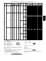
Table 3 – Electrical Data -- Units With Optional Powered Convenience Outlet
NOMINAL
POWER SUPPLY
Volts-Ph-Hz
VOLTAGE
RANGE
Min
Max
COMPRESSOR
RLA
LRA
OFM
FLA
POWER
EXHAUST
FLA
IFM
TYPE
IFM
FLA
Low
—
High
03
208/230-1-60
187
253
12.8
60
1.0
4.9
Low
1.4
High
Low
—
High
208/230-1-60
187
253
15.4
83
1.0
4.9
Low
04
1.4
High
Low
208/230-3-60
187
253
11.5
77
1.0
—
4.9
High
FLA
HACR
IFM
LRA
MCA
MOCP
NEC
OFM
RLA
-------------------
LEGEND
Full Load Amps
Heating, Air Conditioning and Refrigeration
Indoor (Evaporator) Fan Motor
Locked Rotor Amps
Minimum Circuit Amps
Maximum Overcurrent Protection
National Electrical Code
Outdoor (Condenser) Fan Motor
Rated Load Amps
*Heater capacity (kW) is based on heater voltage of 208v, 240v, 480v, or 600v. If power
distribution voltage to unit varies from rated heater voltage, heater kW will vary accordingly.
{ Fuse or HACR circuit breaker.
NOTES:
1. In compliance with NEC requirements for multimotor and combination load equipment (refer
to NEC Articles 430 and 440), the overcurrent protective device for the unit shall be fuse or
HACR breaker. Canadian units may be fuse or circuit breaker.
2. Unbalanced 3-Phase Supply Voltage
Never operate a motor where a phase imbalance in supply voltage is greater than 2%. Use
the following formula to determine the percentage of voltage imbalance.
% Voltage Imbalance
= 100 x
ELECTRIC HEAT
FLA
—
10.8/12.5
17.3/20.0
26.0/30.0
34.7/40.0
—
10.8/12.5
17.3/20.0
26.0/30.0
34.7/40.0
—
10.8/12.5
17.3/20.0
26.0/30.0
34.7/40.0
—
10.8/12.5
17.3/20.0
26.0/30.0
34.7/40.0
—
10.8/12.5
17.3/20.0
26.0/30.0
34.7/40.0
52.0/60.0
—
10.8/12.5
17.3/20.0
26.0/30.0
34.7/40.0
52.0/60.0
—
10.8/12.5
17.3/20.0
26.0/30.0
34.7/40.0
52.0/60.0
—
10.8/12.5
17.3/20.0
26.0/30.0
34.7/40.0
52.0/60.0
—
6.3/ 7.2
10.0/11.5
15.0/17.3
20.0/23.1
30.0/34.6
—
6.3/ 7.2
10.0/11.5
15.0/17.3
20.0/23.1
30.0/34.6
POWER SUPPLY
Nominal
kW*
—
2.3/ 3.0
3.8/ 5.0
5.6/ 7.5
7.5/10.0
—
2.3/ 3.0
3.8/ 5.0
5.6/ 7.5
7.5/10.0
—
2.3/ 3.0
3.8/ 5.0
5.6/ 7.5
7.5/10.0
—
2.3/ 3.0
3.8/ 5.0
5.6/ 7.5
7.5/10.0
—
2.3/ 3.0
3.8/ 5.0
5.6/ 7.5
7.5/10.0
11.3/15.0
—
2.3/ 3.0
3.8/ 5.0
5.6/ 7.5
7.5/10.0
11.3/15.0
—
2.3/ 3.0
3.8/ 5.0
5.6/ 7.5
7.5/10.0
11.3/15.0
—
2.3/ 3.0
3.8/ 5.0
5.6/ 7.5
7.5/10.0
11.3/15.0
—
2.3/ 3.0
3.8/ 5.0
5.6/ 7.5
7.5/10.0
11.3/15.0
—
2.3/ 3.0
3.8/ 5.0
5.6/ 7.5
7.5/10.0
11.3/15.0
DISCONNECT
SIZE
MCA
MOCP†
FLA
LRA
26.7/26.7
26.7/27.8
33.8/37.1
44.6/49.6
55.5/62.1
26.7/26.7
26.7/27.8
33.8/37.1
44.6/49.6
55.5/62.1
28.1/28.1
28.1/29.5
35.5/38.9
46.4/51.4
57.3/63.9
28.1/28.1
28.1/29.5
35.5/38.9
46.4/51.4
57.3/63.9
30.0/30.0
30.0/30.0
33.8/37.1
44.6/49.6
55.5/62.1
77.1/87.1
30.0/30.0
30.0/30.0
33.8/37.1
44.6/49.6
55.5/62.1
77.1/87.1
31.4/31.4
31.4/31.4
35.5/38.9
46.4/51.4
57.3/63.9
78.9/88.9
31.4/31.4
31.4/31.4
35.5/38.9
46.4/51.4
57.3/63.9
78.9/88.9
25.1/25.1
25.1/25.1
25.1/26.5
30.9/33.8
37.1/41.0
49.6/55.4
25.1/25.1
25.1/25.1
25.1/26.5
30.9/33.8
37.1/41.0
49.6/55.4
30/30
30/30
35/40
45/50
60/70
30/30
30/30
35/40
45/50
60/70
30/30
30/30
40/40
50/60
60/70
30/30
30/30
40/40
50/60
60/70
30/30
30/30
35/40
45/50
60/70
80/90
30/30
30/30
35/40
45/50
60/70
80/90
35/35
35/35
40/40
50/60
60/70
80/90
35/35
35/35
40/40
50/60
60/70
80/90
30/30
30/30
30/30
35/35
40/45
50/60
30/30
30/30
30/30
35/35
40/45
50/60
27/27
27/27
31/34
41/46
51/57
27/27
27/27
31/34
41/46
51/57
29/29
29/29
33/36
43/47
53/59
29/29
29/29
33/36
43/47
53/59
30/30
30/30
31/34
41/46
51/57
71/80
30/30
30/30
31/34
41/46
51/57
71/80
32/32
32/32
33/36
43/47
53/59
73/82
32/32
32/32
33/36
43/47
53/59
73/82
26/26
26/26
26/26
28/31
34/38
46/51
26/26
26/26
26/26
28/31
34/38
46/51
79/79
79/79
79/79
79/79
79/79
79/79
79/79
79/79
79/79
79/79
81/81
81/81
81/81
81/81
81/81
81/81
81/81
81/81
81/81
81/81
102/102
102/102
102/102
102/102
102/102
102/102
102/102
102/102
102/102
102/102
102/102
102/102
104/104
104/104
104/104
104/104
104/104
104/104
104/104
104/104
104/104
104/104
104/104
104/104
96/96
96/96
96/96
96/96
96/96
96/96
96/96
96/96
96/96
96/96
96/96
96/96
Example: Supply voltage is 230 ---3 ---60
AB = 224 v
BC = 231 v
AC = 226 v
Average Voltage =
224 + 231 + 226
3
=
681
3
=
227
Determine maximum deviation from average voltage.
(AB) 227 – 224 = 3 v
(BC) 231 – 227 = 4 v
(AC) 227 – 226 = 1 v
Maximum deviation is 4 v.
Determine percent of voltage imbalance.
% Voltage Imbalance
= 100 x
= 1.76%
4
227
This amount of phase imbalance is satisfactory as it is below the maximum allowable 2%.
IMPORTANT: If the supply voltage phase imbalance is more than 2%, contact your local electric
utility company immediately.
max voltage deviation from average voltage
average voltage
17
50PG03-- 07
UNIT
50PG
Table 3 -- Electrical Data -- Units With Optional Powered Convenience Outlet (cont)
UNIT
50PG
NOMINAL
POWER SUPPLY
Volts-Ph-Hz
VOLTAGE
RANGE
Min
Max
COMPRESSOR
RLA
LRA
OFM
FLA
POWER
EXHAUST
FLA
IFM
TYPE
IFM
FLA
Low
208/230-3-60
187
253
11.5
77
1.0
1.4
4.9
High
Low
50PG03-- 07
—
High
04
(cont)
460-3-60
414
506
5.1
35
0.5
2.1
Low
0.6
High
Low
—
High
575-3-60
518
633
4.3
31
0.5
2.1
Low
1.4
High
Low
4.9
High
7.0
Low
4.9
High
7.0
Low
4.9
High
5.2
Low
4.9
High
5.2
—
208/230-1-60
187
253
20.5
109
1.0
1.4
05
—
208/230-3-60
187
253
14.6
91
1.0
1.4
* See Legend on next page.
18
ELECTRIC HEAT
FLA
—
6.3/ 7.2
10.0/11.5
15.0/17.3
20.0/23.1
30.0/34.6
—
6.3/ 7.2
10.0/11.5
15.0/17.3
20.0/23.1
30.0/34.6
—
3.5
5.8
8.7
11.5
17.3
—
3.5
5.8
8.7
11.5
17.3
—
3.5
5.8
8.7
11.5
17.3
—
3.5
5.8
8.7
11.5
17.3
—
9.2
13.9
—
9.2
13.9
—
9.2
13.9
—
9.2
13.9
—
17.3/20.0
26.0/30.0
34.7/40.0
52.0/60.0
69.3/80.0
—
17.3/20.0
26.0/30.0
34.7/40.0
52.0/60.0
69.3/80.0
—
17.3/20.0
26.0/30.0
34.7/40.0
52.0/60.0
69.3/80.0
—
17.3/20.0
26.0/30.0
34.7/40.0
52.0/60.0
69.3/80.0
—
10.0/11.5
15.0/17.3
20.0/23.1
30.0/34.6
40.0/46.2
—
10.0/11.5
15.0/17.3
20.0/23.1
30.0/34.6
40.0/46.2
—
10.0/11.5
15.0/17.3
20.0/23.1
30.0/34.6
40.0/46.2
—
10.0/11.5
15.0/17.3
20.0/23.1
30.0/34.6
40.0/46.2
Nominal
kW*
—
2.3/ 3.0
3.8/ 5.0
5.6/ 7.5
7.5/10.0
11.3/15.0
—
2.3/ 3.0
3.8/ 5.0
5.6/ 7.5
7.5/10.0
11.3/15.0
—
3.0
5.0
7.5
10.0
15.0
—
3.0
5.0
7.5
10.0
15.0
—
3.0
5.0
7.5
10.0
15.0
—
3.0
5.0
7.5
10.0
15.0
—
10.0
15.0
—
10.0
15.0
—
10.0
15.0
—
10.0
15.0
—
3.8/ 5.0
5.6/ 7.5
7.5/10.0
11.3/15.0
15.0/20.0
—
3.8/ 5.0
5.6/ 7.5
7.5/10.0
11.3/15.0
15.0/20.0
—
3.8/ 5.0
5.6/ 7.5
7.5/10.0
11.3/15.0
15.0/20.0
—
3.8/ 5.0
5.6/ 7.5
7.5/10.0
11.3/15.0
15.0/20.0
—
3.8/ 5.0
5.6/ 7.5
7.5/10.0
11.3/15.0
15.0/20.0
—
3.8/ 5.0
5.6/ 7.5
7.5/10.0
11.3/15.0
15.0/20.0
—
3.8/ 5.0
5.6/ 7.5
7.5/10.0
11.3/15.0
15.0/20.0
—
3.8/ 5.0
5.6/ 7.5
7.5/10.0
11.3/15.0
15.0/20.0
POWER SUPPLY
DISCONNECT
SIZE
MCA
MOCP†
FLA
LRA
26.5/26.5
26.5/26.5
26.5/28.3
32.6/35.5
38.9/42.8
51.4/57.1
26.5/26.5
26.5/26.5
26.5/28.3
32.6/35.5
38.9/42.8
51.4/57.1
11.2
11.2
12.6
16.3
19.8
27.0
11.2
11.2
12.6
16.3
19.8
27.0
11.8
11.8
13.4
17.0
20.5
27.8
11.8
11.8
13.4
17.0
20.5
27.8
9.7
16.3
22.1
9.7
16.3
22.1
11.1
18.0
23.9
11.1
18.0
23.9
36.3/ 36.3
36.3/ 37.1
44.6/ 49.6
55.5/ 62.1
77.1/ 87.1
98.8/112.1
38.4/ 38.4
38.4/ 39.8
47.3/ 52.3
58.1/ 64.8
79.8/ 89.8
101.4/114.8
37.7/ 37.7
37.7/ 38.9
46.4/ 51.4
57.3/ 63.9
78.9/ 88.9
100.5/113.9
39.8/ 39.8
39.8/ 41.5
49.0/ 54.0
59.9/ 66.5
81.5/ 91.5
103.1/116.5
29.0/29.0
29.0/29.0
30.9/33.8
37.1/41.0
49.6/55.4
62.1/69.9
29.3/29.3
29.3/29.3
31.3/34.1
37.5/41.4
50.0/55.8
62.5/70.3
30.4/30.4
30.4/30.4
32.6/35.5
38.9/42.8
51.4/57.1
63.9/71.6
30.7/30.7
30.7/30.7
33.0/35.9
39.3/43.1
51.8/57.5
64.3/72.0
30/30
30/30
30/30
35/40
40/45
60/60
30/30
30/30
30/30
35/40
40/45
60/60
15
15
15
20
20
30
15
15
15
20
20
30
15
15
15
20
25
30
15
15
15
20
25
30
15
20
25
15
20
25
15
20
25
15
20
25
40/ 40
40/ 40
45/ 50
60/ 70
80/ 90
100/125
40/ 40
40/ 40
50/ 60
60/ 70
80/ 90
110/125
40/ 40
40/ 40
50/ 60
60/ 70
80/ 90
110/125
40/ 40
40/ 45
50/ 60
60/ 70
90/100
110/125
30/30
30/30
35/35
40/45
50/60
70/70
30/30
30/30
35/35
40/45
60/60
70/80
35/35
35/35
35/40
40/45
60/60
70/80
35/35
35/35
35/40
40/45
60/60
70/80
27/27
27/27
27/27
30/33
36/39
47/53
27/27
27/27
27/27
30/33
36/39
47/53
11
11
12
15
18
25
11
11
12
15
18
25
12
12
12
16
19
26
12
12
12
16
19
26
10
15
20
10
15
20
12
17
22
12
17
22
36/ 36
36/ 36
41/ 46
51/ 57
71/ 80
91/103
38/ 38
38/ 38
43/ 48
53/ 60
73/ 83
93/106
37/ 37
37/ 37
43/ 47
53/ 59
73/ 82
92/105
40/ 40
40/ 40
45/ 50
55/ 61
75/ 84
95/107
29/29
29/29
29/31
34/38
46/51
57/64
29/29
29/29
29/31
35/38
46/51
58/65
31/31
31/31
31/33
36/39
47/53
59/66
31/31
31/31
31/33
36/40
48/53
59/66
98/98
98/98
98/98
98/98
98/98
98/98
98/98
98/98
98/98
98/98
98/98
98/98
44
44
44
44
44
44
44
44
44
44
44
44
45
45
45
45
45
45
45
45
45
45
45
45
39
39
39
39
39
39
41
41
41
41
41
41
128/128
128/128
128/128
128/128
128/128
128/128
153/153
153/153
153/153
153/153
153/153
153/153
130/130
130/130
130/130
130/130
130/130
130/130
155/155
155/155
155/155
155/155
155/155
155/155
110/110
110/110
110/110
110/110
110/110
110/110
128/128
128/128
128/128
128/128
128/128
128/128
112/112
112/112
112/112
112/112
112/112
112/112
130/130
130/130
130/130
130/130
130/130
130/130
Table 3 -- Electrical Data -- Units With Optional Powered Convenience Outlet (cont)
Volts-Ph-Hz
VOLTAGE
RANGE
Min
Max
COMPRESSOR
RLA
LRA
OFM
FLA
POWER
EXHAUST
FLA
IFM
TYPE
IFM
FLA
Low
2.1
High
2.6
Low
2.1
High
2.6
Low
2.1
High
2.0
Low
2.1
High
2.0
Low
4.9
High
7.0
Low
4.9
High
7.0
—
460-3-60
414
506
7.1
46
0.5
0.6
05
(cont)
—
575-3-60
518
633
5.1
34
0.5
1.4
—
06
208/230-1-60
187
253
26.9
145
1.5
1.4
FLA
HACR
IFM
LRA
MCA
MOCP
NEC
OFM
RLA
-------------------
LEGEND
Full Load Amps
Heating, Air Conditioning and Refrigeration
Indoor (Evaporator) Fan Motor
Locked Rotor Amps
Minimum Circuit Amps
Maximum Overcurrent Protection
National Electrical Code
Outdoor (Condenser) Fan Motor
Rated Load Amps
*Heater capacity (kW) is based on heater voltage of 208v, 240v, 480v, or 600v. If power
distribution voltage to unit varies from rated heater voltage, heater kW will vary accordingly.
{ Fuse or HACR circuit breaker.
NOTES:
1. In compliance with NEC requirements for multimotor and combination load equipment (refer
to NEC Articles 430 and 440), the overcurrent protective device for the unit shall be fuse or
HACR breaker. Canadian units may be fuse or circuit breaker.
2. Unbalanced 3-Phase Supply Voltage
Never operate a motor where a phase imbalance in supply voltage is greater than 2%. Use
the following formula to determine the percentage of voltage imbalance.
% Voltage Imbalance
= 100 x
ELECTRIC HEAT
POWER SUPPLY
DISCONNECT
SIZE
FLA
Nominal
kW*
MCA
MOCP†
FLA
LRA
—
5.8
8.7
11.5
17.3
23.1
—
5.8
8.7
11.5
17.3
23.1
—
5.8
8.7
11.5
17.3
23.1
—
5.8
8.7
11.5
17.3
23.1
—
9.2
13.9
18.5
—
9.2
13.9
18.5
—
9.2
13.9
18.5
—
9.2
13.9
18.5
—
17.3/ 20.0
26.0/ 30.0
34.7/ 40.0
52.0/ 60.0
69.3/ 80.0
86.7/100.0
—
17.3/ 20.0
26.0/ 30.0
34.7/ 40.0
52.0/ 60.0
69.3/ 80.0
86.7/100.0
—
17.3/ 20.0
26.0/ 30.0
34.7/ 40.0
52.0/ 60.0
69.3/ 80.0
86.7/100.0
—
17.3/ 20.0
26.0/ 30.0
34.7/ 40.0
52.0/ 60.0
69.3/ 80.0
86.7/100.0
—
5.0
7.5
10.0
15.0
20.0
—
5.0
7.5
10.0
15.0
20.0
—
5.0
7.5
10.0
15.0
20.0
—
5.0
7.5
10.0
15.0
20.0
—
10.0
15.0
20.0
—
10.0
15.0
20.0
—
10.0
15.0
20.0
—
10.0
15.0
20.0
—
3.8/ 5.0
5.6/ 7.5
7.5/10.0
11.3/15.0
15.0/20.0
18.8/25.0
—
3.8/ 5.0
5.6/ 7.5
7.5/10.0
11.3/15.0
15.0/20.0
18.8/25.0
—
3.8/ 5.0
5.6/ 7.5
7.5/10.0
11.3/15.0
15.0/20.0
18.8/25.0
—
3.8/ 5.0
5.6/ 7.5
7.5/10.0
11.3/15.0
15.0/20.0
18.8/25.0
13.7
13.7
16.3
19.8
27.0
34.3
14.2
14.2
16.9
20.4
27.6
34.9
14.3
14.3
17.0
20.5
27.8
35.0
14.8
14.8
17.6
21.1
28.4
35.6
10.7
16.3
22.1
27.9
10.6
16.1
22.0
27.8
12.1
18.0
23.9
29.6
12.0
17.9
23.8
29.5
44.8/ 44.8
44.8/ 44.8
44.8/ 49.6
55.5/ 62.1
77.1/ 87.1
98.8/112.1
120.5/137.1
46.9/ 46.9
46.9/ 46.9
47.3/ 52.3
58.1/ 64.8
79.8/ 89.8
101.4/114.8
123.1/139.8
46.2/ 46.2
46.2/ 46.2
46.4/ 51.4
57.3/ 63.9
78.9/ 88.9
100.5/113.9
122.3/138.9
48.3/ 48.3
48.3/ 48.3
49.0/ 54.0
59.9/ 66.5
81.5/ 91.5
103.1/116.5
124.9/141.5
15
15
20
20
30
35
15
15
20
25
30
35
15
15
20
25
30
40
15
15
20
25
30
40
15
20
25
30
15
20
25
30
15
20
25
30
15
20
25
30
50/ 50
50/ 50
50/ 50
60/ 70
80/ 90
100/125
125/150
50/ 50
50/ 50
50/ 60
60/ 70
80/ 90
110/125
125/150
50/ 50
50/ 50
50/ 60
60/ 70
80/ 90
110/125
125/150
50/ 50
50/ 50
50/ 60
60/ 70
90/100
110/125
125/150
14
14
15
18
25
32
14
14
16
19
25
32
14
14
16
19
26
32
15
15
16
19
26
33
11
15
20
26
11
15
20
26
12
17
22
27
12
16
22
27
44/44
44/44
44/46
51/57
71/80
91/103
111/126
46/ 46
46/ 46
46/ 48
53/ 60
73/ 83
93/106
113/129
45/ 45
45/ 45
45/ 47
53/ 59
73/ 82
92/105
112/128
48/ 48
48/ 48
48/ 50
55/ 61
75/ 84
95/107
115/130
55
55
55
55
55
55
64
64
64
64
64
64
56
56
56
56
56
56
65
65
65
65
65
65
42
42
42
42
48
48
48
48
44
44
44
44
50
50
50
50
165/165
165/165
165/165
165/165
165/165
165/165
165/165
190/190
190/190
190/190
190/190
190/190
190/190
190/190
167/167
167/167
167/167
167/167
167/167
167/167
167/167
192/192
192/192
192/192
192/192
192/192
192/192
192/192
Example: Supply voltage is 230 ---3 ---60
AB = 224 v
BC = 231 v
AC = 226 v
Average Voltage =
224 + 231 + 226
3
=
681
3
=
227
Determine maximum deviation from average voltage.
(AB) 227 – 224 = 3 v
(BC) 231 – 227 = 4 v
(AC) 227 – 226 = 1 v
Maximum deviation is 4 v.
Determine percent of voltage imbalance.
% Voltage Imbalance
= 100 x
= 1.76%
4
227
This amount of phase imbalance is satisfactory as it is below the maximum allowable 2%.
IMPORTANT: If the supply voltage phase imbalance is more than 2%, contact your local electric
utility company immediately.
max voltage deviation from average voltage
average voltage
19
50PG03-- 07
NOMINAL
POWER SUPPLY
UNIT
50PG
Table 3 -- Electrical Data -- Units With Optional Powered Convenience Outlet (cont)
UNIT
50PG
NOMINAL
POWER SUPPLY
Volts-Ph-Hz
VOLTAGE
RANGE
Min
Max
COMPRESSOR
RLA
LRA
OFM
FLA
POWER
EXHAUST
FLA
IFM
TYPE
IFM
FLA
Low
—
High
208/230-3-60
187
253
17.6
123
1.5
5.2
50PG03-- 07
Low
1.4
High
Low
—
06
(cont)
High
460-3-60
414
506
7.7
50
0.8
2.6
Low
0.6
High
Low
—
High
575-3-60
518
633
6.1
40
0.8
2.0
Low
1.4
High
07
208/230-3-60
187
253
20.5
149
1.5
Low
5.2
High
7.5
—
* See Legend on next page.
20
ELECTRIC HEAT
FLA
—
10.0/11.5
15.0/17.3
20.0/23.1
30.0/34.6
40.0/46.2
50.0/57.7
—
10.0/11.5
15.0/17.3
20.0/23.1
30.0/34.6
40.0/46.2
50.0/57.7
—
10.0/11.5
15.0/17.3
20.0/23.1
30.0/34.6
40.0/46.2
50.0/57.7
—
10.0/11.5
15.0/17.3
20.0/23.1
30.0/34.6
40.0/46.2
50.0/57.7
—
5.8
8.7
11.5
17.3
23.1
28.9
—
5.8
8.7
11.5
17.3
23.1
28.9
—
5.8
8.7
11.5
17.3
23.1
28.9
—
5.8
8.7
11.5
17.3
23.1
28.9
—
9.2
13.9
18.5
23.1
—
9.2
13.9
18.5
23.1
—
9.2
13.9
18.5
23.1
—
9.2
13.9
18.5
23.1
—
10.0/11.5
15.0/17.3
20.0/23.1
30.0/34.6
40.0/46.2
50.0/57.7
—
10.0/11.5
15.0/17.3
20.0/23.1
30.0/34.6
40.0/46.2
50.0/57.7
Nominal
kW*
—
3.8/ 5.0
5.6/ 7.5
7.5/10.0
11.3/15.0
15.0/20.0
18.8/25.0
—
3.8/ 5.0
5.6/ 7.5
7.5/10.0
11.3/15.0
15.0/20.0
18.8/25.0
—
3.8/ 5.0
5.6/ 7.5
7.5/10.0
11.3/15.0
15.0/20.0
18.8/25.0
—
3.8/ 5.0
5.6/ 7.5
7.5/10.0
11.3/15.0
15.0/20.0
18.8/25.0
—
5.0
7.5
10.0
15.0
20.0
25.0
—
5.0
7.5
10.0
15.0
20.0
25.0
—
5.0
7.5
10.0
15.0
20.0
25.0
—
5.0
7.5
10.0
15.0
20.0
25.0
—
10.0
15.0
20.0
25.0
—
10.0
15.0
20.0
25.0
—
10.0
15.0
20.0
25.0
—
10.0
15.0
20.0
25.0
—
3.8/ 5.0
5.6/ 7.5
7.5/10.0
11.3/15.0
15.0/20.0
18.8/25.0
—
3.8/ 5.0
5.6/ 7.5
7.5/10.0
11.3/15.0
15.0/20.0
18.8/25.0
POWER SUPPLY
DISCONNECT
SIZE
MCA
MOCP†
FLA
LRA
33.5/33.5
33.5/33.5
33.5/34.1
37.5/41.4
50.0/55.8
62.5/70.3
75.0/84.6
33.5/33.5
33.5/33.5
33.5/34.1
37.5/41.4
50.0/55.8
62.5/70.3
75.0/84.6
34.9/34.9
34.9/34.9
34.9/35.9
39.3/43.1
51.8/57.5
64.3/72.0
76.8/86.4
34.9/34.9
34.9/34.9
34.9/35.9
39.3/43.1
51.8/57.5
64.3/72.0
76.8/86.4
15.2
15.2
16.9
20.4
27.6
34.9
42.1
15.2
15.2
16.9
20.4
27.6
34.9
42.1
15.8
15.8
17.6
21.1
28.4
35.6
42.9
15.8
15.8
17.6
21.1
28.4
35.6
42.9
12.1
16.1
22.0
27.8
33.5
12.1
16.1
22.0
27.8
33.5
13.5
17.9
23.8
29.5
35.3
13.5
17.9
23.8
29.5
35.3
37.1/37.1
37.1/37.1
37.1/37.1
37.5/41.4
50.0/55.8
62.5/70.3
75.0/84.6
39.4/39.4
39.4/39.4
39.4/39.4
40.4/44.3
52.9/58.6
65.4/73.1
77.9/87.5
35/35
35/35
35/35
40/45
60/60
70/80
80/90
35/35
35/35
35/35
40/45
60/60
70/80
80/90
35/35
35/35
35/40
40/45
60/60
70/80
80/90
35/35
35/35
35/40
40/45
60/60
70/80
80/90
20
20
20
25
30
35
45
20
20
20
25
30
35
45
20
20
20
25
30
40
45
20
20
20
25
30
40
45
15
20
25
30
35
15
20
25
30
35
15
20
25
30
40
15
20
25
30
40
40/40
40/40
40/40
40/45
60/60
70/80
80/90
40/40
40/40
40/40
45/45
60/60
70/80
80/90
33/33
33/33
33/33
35/38
46/51
58/65
69/78
33/33
33/33
33/33
35/38
46/51
58/65
69/78
35/35
35/35
35/35
36/40
48/53
59/66
71/79
35/35
35/35
35/35
36/40
48/53
59/66
71/79
15
15
16
19
25
32
39
15
15
16
19
25
32
39
16
16
16
19
26
33
39
16
16
16
19
26
33
39
12
15
20
26
31
12
15
20
26
31
14
16
22
27
32
14
16
22
27
32
37/37
37/37
37/37
37/38
46/51
58/65
69/78
39/39
39/39
39/39
39/41
49/54
60/67
72/81
161/161
161/161
161/161
161/161
161/161
161/161
161/161
161/161
161/161
161/161
161/161
161/161
161/161
161/161
163/163
163/163
163/163
163/163
163/163
163/163
163/163
163/163
163/163
163/163
163/163
163/163
163/163
163/163
69
69
69
69
69
69
69
69
69
69
69
69
69
69
70
70
70
70
70
70
70
70
70
70
70
70
70
70
55
55
55
55
55
55
55
55
55
55
57
57
57
57
57
57
57
57
57
57
187/187
187/187
187/187
187/187
187/187
187/187
187/187
213/213
213/213
213/213
213/213
213/213
213/213
213/213
NOMINAL
POWER SUPPLY
UNIT
50PG
Volts-Ph-Hz
208/230-3-60
VOLTAGE
RANGE
Min
187
Max
253
COMPRESSOR
RLA
20.5
LRA
149
OFM
FLA
POWER
EXHAUST
FLA
1.5
IFM
TYPE
IFM
FLA
Low
5.2
High
7.5
Low
2.6
High
3.4
Low
2.6
High
3.4
Low
2.0
High
2.8
Low
2.0
High
2.8
1.4
—
460-3-60
414
506
9.6
75
0.8
07
(cont)
0.6
—
575-3-60
518
633
7.6
54
0.8
1.4
FLA
HACR
IFM
LRA
MCA
MOCP
NEC
OFM
RLA
-------------------
LEGEND
Full Load Amps
Heating, Air Conditioning and Refrigeration
Indoor (Evaporator) Fan Motor
Locked Rotor Amps
Minimum Circuit Amps
Maximum Overcurrent Protection
National Electrical Code
Outdoor (Condenser) Fan Motor
Rated Load Amps
*Heater capacity (kW) is based on heater voltage of 208v, 240v, 480v, or 600v. If power
distribution voltage to unit varies from rated heater voltage, heater kW will vary accordingly.
{ Fuse or HACR circuit breaker.
NOTES:
1. In compliance with NEC requirements for multimotor and combination load equipment (refer
to NEC Articles 430 and 440), the overcurrent protective device for the unit shall be fuse or
HACR breaker. Canadian units may be fuse or circuit breaker.
2. Unbalanced 3-Phase Supply Voltage
Never operate a motor where a phase imbalance in supply voltage is greater than 2%. Use
the following formula to determine the percentage of voltage imbalance.
% Voltage Imbalance
= 100 x
ELECTRIC HEAT
FLA
—
10.0/11.5
15.0/17.3
20.0/23.1
30.0/34.6
40.0/46.2
50.0/57.7
—
10.0/11.5
15.0/17.3
20.0/23.1
30.0/34.6
40.0/46.2
50.0/57.7
—
5.8
8.7
11.5
17.3
23.1
28.9
—
5.8
8.7
11.5
17.3
23.1
28.9
—
5.8
8.7
11.5
17.3
23.1
28.9
—
5.8
8.7
11.5
17.3
23.1
28.9
—
9.2
13.9
18.5
23.1
27.7
—
9.2
13.9
18.5
23.1
27.7
—
9.2
13.9
18.5
23.1
27.7
—
9.2
13.9
18.5
23.1
27.7
Nominal
kW*
—
3.8/ 5.0
5.6/ 7.5
7.5/10.0
11.3/15.0
15.0/20.0
18.8/25.0
—
3.8/ 5.0
5.6/ 7.5
7.5/10.0
11.3/15.0
15.0/20.0
18.8/25.0
—
5.0
7.5
10.0
15.0
20.0
25.0
—
5.0
7.5
10.0
15.0
20.0
25.0
—
5.0
7.5
10.0
15.0
20.0
25.0
—
5.0
7.5
10.0
15.0
20.0
25.0
—
10.0
15.0
20.0
25.0
30.0
—
10.0
15.0
20.0
25.0
30.0
—
10.0
15.0
20.0
25.0
30.0
—
10.0
15.0
20.0
25.0
30.0
POWER SUPPLY
DISCONNECT
SIZE
MCA
MOCP†
FLA
LRA
38.5/38.5
38.5/38.5
38.5/38.5
39.3/43.1
51.8/57.5
64.3/72.0
76.8/86.4
40.8/40.8
40.8/40.8
40.8/40.8
42.1/46.0
54.6/60.4
67.1/74.9
79.6/89.3
17.6
17.6
17.6
20.4
27.6
34.9
42.1
18.4
18.4
18.4
21.4
28.6
35.9
43.1
18.2
18.2
18.2
21.1
28.4
35.6
42.9
19.0
19.0
19.0
22.1
29.4
36.6
43.9
14.0
16.1
22.0
27.8
33.5
39.3
14.8
17.1
23.0
28.8
34.5
40.3
15.4
17.9
23.8
29.5
35.3
41.0
16.2
18.9
24.8
30.5
36.3
42.0
40/40
40/40
40/40
40/45
60/60
70/80
80/90
45/45
45/45
45/45
45/50
60/70
70/80
80/90
20
20
20
25
30
35
45
20
20
20
25
30
40
45
20
20
20
25
30
40
45
20
20
20
25
30
40
45
15
20
25
30
35
40
15
20
25
30
35
45
20
20
25
30
40
45
20
20
25
35
40
45
38/38
38/38
38/38
38/40
48/53
59/66
71/79
41/41
41/41
41/41
41/42
50/56
62/69
73/82
17
17
17
19
25
32
39
18
18
18
20
26
33
40
18
18
18
19
26
33
39
19
19
19
20
27
34
40
14
15
20
26
31
36
15
16
21
26
32
37
16
16
22
27
32
38
16
17
23
28
33
39
189/189
189/189
189/189
189/189
189/189
189/189
189/189
215/215
215/215
215/215
215/215
215/215
215/215
215/215
94
94
94
94
94
94
94
107
107
107
107
107
107
107
95
95
95
95
95
95
95
108
108
108
108
108
108
108
69
69
69
69
69
69
80
80
80
80
80
80
71
71
71
71
71
71
82
82
82
82
82
82
Example: Supply voltage is 230 ---3 ---60
AB = 224 v
BC = 231 v
AC = 226 v
Average Voltage =
224 + 231 + 226
3
=
681
3
=
227
Determine maximum deviation from average voltage.
(AB) 227 – 224 = 3 v
(BC) 231 – 227 = 4 v
(AC) 227 – 226 = 1 v
Maximum deviation is 4 v.
Determine percent of voltage imbalance.
% Voltage Imbalance
= 100 x
= 1.76%
4
227
This amount of phase imbalance is satisfactory as it is below the maximum allowable 2%.
IMPORTANT: If the supply voltage phase imbalance is more than 2%, contact your local electric
utility company immediately.
max voltage deviation from average voltage
average voltage
21
50PG03-- 07
Table 3 -- Electrical Data -- Units With Optional Powered Convenience Outlet (cont)
Step 7 — Install Outdoor Air Hoods (Units with
Economizer)
50PG03-- 07
Perform the following procedure to install the outdoor--air hoods:
1. Economizer and barometric relief hoods are located in the
condenser section under the slanted coil for shipping. (See
Fig. 14.) Barometric relief/power exhaust hood is shipped
inside of economizer hood. Remove screws that secure the
wooden rails of the hood assemblies to the unit. Save
screws. Slide complete assembly from condenser section.
2. Remove the screws that secure the economizer and
barometric relief/power exhaust hoods to the wooden
railing. Discard or recycle wooden rails. Save screws.
3. The barometric relief damper is factory mounted onto the
economizer panel for shipping. Remove the screw holding
the barometric relief damper to the panel. Damper should be
free to swing open during operation. (See Fig. 15.)
4. Hang the barometric relief/power exhaust hood on the
mounting flange on the economizer panel. Secure hood to
panel with screws saved from Step 2. (See Fig. 15 and 16.)
5. Align hole in flange of economizer panel with left edge of
hood. Hang economizer hood on the top flange of the
economizer panel by rotating hood until top flange of the
economizer hood engages the bent flange on the
economizer panel. Rotate hood until hood is flush with the
economizer panel. Hood will support itself from flange.
Align holes in hood with holes in panel and secure hood to
panel with screws saved from Step 2. (See Fig. 16 and 17.)
Step 8 — Install All Accessories
After all of the factory--installed options have been adjusted, install
all field--installed accessories. Refer to the accessory installation
instructions included with each accessory. Consult the Carrier Price
Pages for accessory package numbers for particular applications.
POWER EXHAUST/
BAROMETRIC
RELIEF HOOD
POWER EXHAUST/
BAROMETRIC
RELIEF HOOD
MOUNTING
FLANGE
ECONOMIZER
HOOD
WOODEN RAILS
C06262
C06290
Fig. 16 -- Barometric Relief/Power Exhaust
Hood Flange
Fig. 14 -- Economizer and Baromatric
Relief/Power Exhaust Hoods Shipping Positions
MOUNTING
FLANGE
ECONOMIZER
HOOD
ECONOMIZER
HOOD
POWER EXHAUST/
BAROMETRIC
RELIEF HOOD
ECONOMIZER
PANEL
BAROMETRIC
RELIEF DAMPER SCREW
C06260
Fig. 15 -- Hood Installation
C06263
Fig. 17 -- Economizer Flange
Copyright 2010 Carrier Corp. S 7310 W. Morris St. S Indianapolis, IN 46231
Printed in U.S.A.
Edition Date: 03/10
Manufacturer reserves the right to change, at any time, specifications and designs without notice and without obligations.
22
Catalog No:50PG ---40SI
Replaces: 50PG--- 36SI