Download Cabletron Systems 9H531-24 Network Card User Manual
Transcript
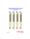
SmartSwitch 9000 9H532-24, 9H533-24, 9H531-24 and 9H539-24 24 Port Fast Ethernet Module User’s Guide 9033050-02 Notice NOTICE Cabletron Systems reserves the right to make changes in specifications and other information contained in this document without prior notice. The reader should in all cases consult Cabletron Systems to determine whether any such changes have been made. The hardware, firmware, or software described in this manual is subject to change without notice. IN NO EVENT SHALL CABLETRON SYSTEMS BE LIABLE FOR ANY INCIDENTAL, INDIRECT, SPECIAL, OR CONSEQUENTIAL DAMAGES WHATSOEVER (INCLUDING BUT NOT LIMITED TO LOST PROFITS) ARISING OUT OF OR RELATED TO THIS MANUAL OR THE INFORMATION CONTAINED IN IT, EVEN IF CABLETRON SYSTEMS HAS BEEN ADVISED OF, KNOWN, OR SHOULD HAVE KNOWN, THE POSSIBILITY OF SUCH DAMAGES. Cabletron Systems, Inc. 35 Industrial Way Rochester, NH 03867 1999 by Cabletron Systems, Inc. All Rights Reserved Printed in the United States of America Order Number: 9033050-02 Cabletron Systems, LANVIEW, and MicroMMAC are registered trademarks and SmartSwitch is a trademark of Cabletron Systems, Inc. All other product names mentioned in this manual may be trademarks or registered trademarks of their respective companies. FCC NOTICE This device complies with Part 15 of the FCC rules. Operation is subject to the following two conditions: (1) this device may not cause harmful interference, and (2) this device must accept any interference received, including interference that may cause undesired operation. NOTE: This equipment has been tested and found to comply with the limits for a Class A digital device, pursuant to Part 15 of the FCC rules. These limits are designed to provide reasonable protection against harmful interference when the equipment is operated in a commercial environment. This equipment uses, generates, and can radiate radio frequency energy and if not installed in accordance with the operator’s manual, may cause harmful interference to radio communications. Operation of this equipment in a residential area is likely to cause interference in which case the user will be required to correct the interference at his own expense. WARNING: Changes or modifications made to this device which are not expressly approved by the party responsible for compliance could void the user’s authority to operate the equipment. INDUSTRY CANADA NOTICE This digital apparatus does not exceed the Class A limits for radio noise emissions from digital apparatus set out in the Radio Interference Regulations of the Canadian Department of Communications. Le présent appareil numérique n’émet pas de bruits radioélectriques dépassant les limites applicables aux appareils numériques de la class A prescrites dans le Règlement sur le brouillage radioélectrique édicté par le ministère des Communications du Canada. VCCI NOTICE This is a Class A product based on the standard of the Voluntary Control Council for Interference by Information Technology Equipment (VCCI). If this equipment is used in a domestic environment, radio disturbance may arise. When such trouble occurs, the user may be required to take corrective actions. i Notice CABLETRON SYSTEMS, INC. PROGRAM LICENSE AGREEMENT IMPORTANT: THIS LICENSE APPLIES FOR USE OF PRODUCT IN THE FOLLOWING GEOGRAPHICAL REGIONS: CANADA MEXICO CENTRAL AMERICA SOUTH AMERICA BEFORE OPENING OR UTILIZING THE ENCLOSED PRODUCT, CAREFULLY READ THIS LICENSE AGREEMENT. This document is an agreement (“Agreement”) between You, the end user, and Cabletron Systems, Inc. (“Cabletron”) that sets forth your rights and obligations with respect to the Cabletron software program (“Program”) in the package. The Program may be contained in firmware, chips or other media. UTILIZING THE ENCLOSED PRODUCT, YOU ARE AGREEING TO BECOME BOUND BY THE TERMS OF THIS AGREEMENT, WHICH INCLUDES THE LICENSE AND THE LIMITATION OF WARRANTY AND DISCLAIMER OF LIABILITY. IF YOU DO NOT AGREE TO THE TERMS OF THIS AGREEMENT, RETURN THE UNOPENED PRODUCT TO CABLETRON OR YOUR DEALER, IF ANY, WITHIN TEN (10) DAYS FOLLOWING THE DATE OF RECEIPT FOR A FULL REFUND. IF YOU HAVE ANY QUESTIONS ABOUT THIS AGREEMENT, CONTACT CABLETRON SYSTEMS +1-603-332-9400. Attn: Legal Department. 1. LICENSE. You have the right to use only the one (1) copy of the Program provided in this package subject to the terms and conditions of this License Agreement. You may not copy, reproduce or transmit any part of the Program except as permitted by the Copyright Act of the United States or as authorized in writing by Cabletron. 2. OTHER RESTRICTIONS. You may not reverse engineer, decompile, or disassemble the Program. 3. APPLICABLE LAW. This License Agreement shall be interpreted and governed under the laws and in the state and federal courts of New Hampshire. You accept the personal jurisdiction and venue of the New Hampshire courts. 4. EXPORT REQUIREMENTS. You understand that Cabletron and its Affiliates are subject to regulation by agencies of the U.S. Government, including the U.S. Department of Commerce, which prohibit export or diversion of certain technical products to certain countries, unless a license to export the product is obtained from the U.S. Government or an exception from obtaining such license may be relied upon by the exporting party. If the Program is exported from the United States pursuant to the License Exception CIV under the U.S. Export Administration Regulations, You agree that You are a civil end user of the Program and agree that You will use the Program for civil end uses only and not for military purposes. If the Program is exported from the United States pursuant to the License Exception TSR under the U.S. Export Administration Regulations, in addition to the restriction on transfer set forth in Sections 1 or 2 of this Agreement, You agree not to (i) reexport or release the Program, the source code for the Program or technology to a national of a country in Country Groups D:1 or E:2 (Albania, Armenia, Azerbaijan, Belarus, Bulgaria, Cambodia, Cuba, Estonia, Georgia, Iraq, Kazakhstan, Kyrgyzstan, Laos, Latvia, Libya, Lithuania, Moldova, North Korea, the People’s Republic of China, Romania, Russia, Rwanda, Tajikistan, Turkmenistan, Ukraine, Uzbekistan, Vietnam, or such other countries as may be designated by the United States Government), (ii) export to Country Groups D:1 or E:2 (as defined herein) the direct product of the Program or the technology, if such foreign produced direct product is subject to national security controls as identified on the U.S. Commerce Control List, or (iii) if the direct product of the technology is a complete plant o r any major component of a plant, export to Country Groups D:1 or E:2 the direct product of the plant or a major component thereof, if such foreign produced direct product is subject to national security controls as identified on the U.S. Commerce Control List or is subject to State Department controls under the U.S. Munitions List. 5. UNITED STATES GOVERNMENT RESTRICTED RIGHTS. The enclosed Product (i) was developed solely at private expense; (ii) contains “restricted computer software” submitted with restricted rights in accordance with section 52.227-19 (a) through (d) of the Commercial Computer Software-Restricted Rights Clause and its successors, and (iii) in all respects is proprietary data belonging to Cabletron and/or its suppliers. For Department of Defense units, the Product is considered commercial computer software in accordance with DFARS section 227.7202-3 and its successors, and use, duplication, or disclosure by the Government is subject to restrictions set forth herein. ii Notice 6. EXCLUSION OF WARRANTY. Except as may be specifically provided by Cabletron in writing, Cabletron makes no warranty, expressed or implied, concerning the Program (including its documentation and media). CABLETRON DISCLAIMS ALL WARRANTIES, OTHER THAN THOSE SUPPLIED TO YOU BY CABLETRON IN WRITING, EITHER EXPRESS OR IMPLIED, INCLUDING BUT NOT LIMITED TO IMPLIED WARRANTIES OF MERCHANTABILITY AND FITNESS FOR A PARTICULAR PURPOSE, WITH RESPECT TO THE PROGRAM, THE ACCOMPANYING WRITTEN MATERIALS, AND ANY ACCOMPANYING HARDWARE. 7. NO LIABILITY FOR CONSEQUENTIAL DAMAGES. IN NO EVENT SHALL CABLETRON OR ITS SUPPLIERS BE LIABLE FOR ANY DAMAGES WHATSOEVER (INCLUDING, WITHOUT LIMITATION, DAMAGES FOR LOSS OF BUSINESS, PROFITS, BUSINESS INTERRUPTION, LOSS OF BUSINESS INFORMATION, SPECIAL, INCIDENTAL, CONSEQUENTIAL, OR RELIANCE DAMAGES, OR OTHER LOSS) ARISING OUT OF THE USE OR INABILITY TO USE THIS CABLETRON PRODUCT, EVEN IF CABLETRON HAS BEEN ADVISED OF THE POSSIBILITY OF SUCH DAMAGES. BECAUSE SOME STATES DO NOT ALLOW THE EXCLUSION OR LIMITATION OF LIABILITY FOR CONSEQUENTIAL OR INCIDENTAL DAMAGES, OR IN THE DURATION OR LIMITATION OF IMPLIED WARRANTIES IN SOME INSTANCES, THE ABOVE LIMITATION AND EXCLUSIONS MAY NOT APPLY TO YOU. CABLETRON SYSTEMS SALES AND SERVICE, INC. PROGRAM LICENSE AGREEMENT IMPORTANT: THIS LICENSE APPLIES FOR USE OF PRODUCT IN THE UNITED STATES OF AMERICA AND BY UNITED STATES OF AMERICA GOVERNMENT END USERS. BEFORE OPENING OR UTILIZING THE ENCLOSED PRODUCT, CAREFULLY READ THIS LICENSE AGREEMENT. This document is an agreement (“Agreement”) between You, the end user, and Cabletron Systems Sales and Service, Inc. (“Cabletron”) that sets forth your rights and obligations with respect to the Cabletron software program (“Program”) in the package. The Program may be contained in firmware, chips or other media. UTILIZING THE ENCLOSED PRODUCT, YOU ARE AGREEING TO BECOME BOUND BY THE TERMS OF THIS AGREEMENT, WHICH INCLUDES THE LICENSE AND THE LIMITATION OF WARRANTY AND DISCLAIMER OF LIABILITY. IF YOU DO NOT AGREE TO THE TERMS OF THIS AGREEMENT, RETURN THE UNOPENED PRODUCT TO CABLETRON OR YOUR DEALER, IF ANY, WITHIN TEN (10) DAYS FOLLOWING THE DATE OF RECEIPT FOR A FULL REFUND. IF YOU HAVE ANY QUESTIONS ABOUT THIS AGREEMENT, CONTACT CABLETRON SYSTEMS +1-603-332-9400. Attn: Legal Department. 1. LICENSE. You have the right to use only the one (1) copy of the Program provided in this package subject to the terms and conditions of this License Agreement. You may not copy, reproduce or transmit any part of the Program except as permitted by the Copyright Act of the United States or as authorized in writing by Cabletron. 2. OTHER RESTRICTIONS. You may not reverse engineer, decompile, or disassemble the Program. 3. APPLICABLE LAW. This License Agreement shall be interpreted and governed under the laws and in the state and federal courts of New Hampshire. You accept the personal jurisdiction and venue of the New Hampshire courts. 4. EXPORT REQUIREMENTS. You understand that Cabletron and its Affiliates are subject to regulation by agencies of the U.S. Government, including the U.S. Department of Commerce, which prohibit export or diversion of certain technical products to certain countries, unless a license to export the product is obtained from the U.S. Government or an exception from obtaining such license may be relied upon by the exporting party. If the Program is exported from the United States pursuant to the License Exception CIV under the U.S. Export Administration Regulations, You agree that You are a civil end user of the Program and agree that You will use the Program for civil end uses only and not for military purposes. If the Program is exported from the United States pursuant to the License Exception TSR under the U.S. Export Administration Regulations, in addition to the restriction on transfer set forth in Sections 1 or 2 of this Agreement, You agree not to (i) reexport or release the Program, the source code for the Program or technology to a national of a country in Country Groups D:1 or E:2 (Albania, Armenia, Azerbaijan, Belarus, Bulgaria, Cambodia, Cuba, Estonia, Georgia, Iraq, Kazakhstan, Kyrgyzstan, Laos, Latvia, Libya, Lithuania, Moldova, North Korea, the People’s Republic of China, Romania, Russia, Rwanda, Tajikistan, Turkmenistan, Ukraine, Uzbekistan, Vietnam, or such other countries as may be designated by the United States Government), (ii) export to Country Groups D:1 or E:2 (as defined herein) the direct product of the Program or the technology, if such foreign produced direct product is subject to national security controls as identified on the U.S. Commerce Control List, or (iii) if the direct product of the technology is a complete plant o r any major component of a plant, iii Notice export to Country Groups D:1 or E:2 the direct product of the plant or a major component thereof, if such foreign produced direct product is subject to national security controls as identified on the U.S. Commerce Control List or is subject to State Department controls under the U.S. Munitions List. 5. UNITED STATES GOVERNMENT RESTRICTED RIGHTS. The enclosed Product (i) was developed solely at private expense; (ii) contains “restricted computer software” submitted with restricted rights in accordance with section 52.227-19 (a) through (d) of the Commercial Computer Software-Restricted Rights Clause and its successors, and (iii) in all respects is proprietary data belonging to Cabletron and/or its suppliers. For Department of Defense units, the Product is considered commercial computer software in accordance with DFARS section 227.7202-3 and its successors, and use, duplication, or disclosure by the Government is subject to restrictions set forth herein. 6. EXCLUSION OF WARRANTY. Except as may be specifically provided by Cabletron in writing, Cabletron makes no warranty, expressed or implied, concerning the Program (including its documentation and media). CABLETRON DISCLAIMS ALL WARRANTIES, OTHER THAN THOSE SUPPLIED TO YOU BY CABLETRON IN WRITING, EITHER EXPRESS OR IMPLIED, INCLUDING BUT NOT LIMITED TO IMPLIED WARRANTIES OF MERCHANTABILITY AND FITNESS FOR A PARTICULAR PURPOSE, WITH RESPECT TO THE PROGRAM, THE ACCOMPANYING WRITTEN MATERIALS, AND ANY ACCOMPANYING HARDWARE. 7. NO LIABILITY FOR CONSEQUENTIAL DAMAGES. IN NO EVENT SHALL CABLETRON OR ITS SUPPLIERS BE LIABLE FOR ANY DAMAGES WHATSOEVER (INCLUDING, WITHOUT LIMITATION, DAMAGES FOR LOSS OF BUSINESS, PROFITS, BUSINESS INTERRUPTION, LOSS OF BUSINESS INFORMATION, SPECIAL, INCIDENTAL, CONSEQUENTIAL, OR RELIANCE DAMAGES, OR OTHER LOSS) ARISING OUT OF THE USE OR INABILITY TO USE THIS CABLETRON PRODUCT, EVEN IF CABLETRON HAS BEEN ADVISED OF THE POSSIBILITY OF SUCH DAMAGES. BECAUSE SOME STATES DO NOT ALLOW THE EXCLUSION OR LIMITATION OF LIABILITY FOR CONSEQUENTIAL OR INCIDENTAL DAMAGES, OR IN THE DURATION OR LIMITATION OF IMPLIED WARRANTIES IN SOME INSTANCES, THE ABOVE LIMITATION AND EXCLUSIONS MAY NOT APPLY TO YOU. CABLETRON SYSTEMS LIMITED PROGRAM LICENSE AGREEMENT IMPORTANT: THIS LICENSE APPLIES FOR THE USE OF THE PRODUCT IN THE FOLLOWING GEOGRAPHICAL REGIONS: EUROPE MIDDLE EAST AFRICA ASIA AUSTRALIA PACIFIC RIM BEFORE OPENING OR UTILIZING THE ENCLOSED PRODUCT, CAREFULLY READ THIS LICENSE AGREEMENT. This document is an agreement (“Agreement”) between You, the end user, and Cabletron Systems Limited (“Cabletron”) that sets forth your rights and obligations with respect to the Cabletron software program (“Program”) in the package. The Program may be contained in firmware, chips or other media. UTILIZING THE ENCLOSED PRODUCT, YOU ARE AGREEING TO BECOME BOUND BY THE TERMS OF THIS AGREEMENT, WHICH INCLUDES THE LICENSE AND THE LIMITATION OF WARRANTY AND DISCLAIMER OF LIABILITY. IF YOU DO NOT AGREE TO THE TERMS OF THIS AGREEMENT, RETURN THE UNOPENED PRODUCT TO CABLETRON OR YOUR DEALER, IF ANY, WITHIN TEN (10) DAYS FOLLOWING THE DATE OF RECEIPT FOR A FULL REFUND. IF YOU HAVE ANY QUESTIONS ABOUT THIS AGREEMENT, CONTACT CABLETRON SYSTEMS +1-603-332-9400. Attn: Legal Department. 1. LICENSE. You have the right to use only the one (1) copy of the Program provided in this package subject to the terms and conditions of this License Agreement. You may not copy, reproduce or transmit any part of the Program except as permitted by the Copyright Act of the United States or as authorized in writing by Cabletron. 2. 3. OTHER RESTRICTIONS. You may not reverse engineer, decompile, or disassemble the Program. APPLICABLE LAW. This License Agreement shall be governed in accordance with English law. The English courts shall have exclusive jurisdiction in the event of any disputes. iv Notice 4. EXPORT REQUIREMENTS. You understand that Cabletron and its Affiliates are subject to regulation by agencies of the U.S. Government, including the U.S. Department of Commerce, which prohibit export or diversion of certain technical products to certain countries, unless a license to export the product is obtained from the U.S. Government or an exception from obtaining such license may be relied upon by the exporting party. If the Program is exported from the United States pursuant to the License Exception CIV under the U.S. Export Administration Regulations, You agree that You are a civil end user of the Program and agree that You will use the Program for civil end uses only and not for military purposes. If the Program is exported from the United States pursuant to the License Exception TSR under the U.S. Export Administration Regulations, in addition to the restriction on transfer set forth in Sections 1 or 2 of this Agreement, You agree not to (i) reexport or release the Program, the source code for the Program or technology to a national of a country in Country Groups D:1 or E:2 (Albania, Armenia, Azerbaijan, Belarus, Bulgaria, Cambodia, Cuba, Estonia, Georgia, Iraq, Kazakhstan, Kyrgyzstan, Laos, Latvia, Libya, Lithuania, Moldova, North Korea, the People’s Republic of China, Romania, Russia, Rwanda, Tajikistan, Turkmenistan, Ukraine, Uzbekistan, Vietnam, or such other countries as may be designated by the United States Government), (ii) export to Country Groups D:1 or E:2 (as defined herein) the direct product of the Program or the technology, if such foreign produced direct product is subject to national security controls as identified on the U.S. Commerce Control List, or (iii) if the direct product of the technology is a complete plant o r any major component of a plant, export to Country Groups D:1 or E:2 the direct product of the plant or a major component thereof, if such foreign produced direct product is subject to national security controls as identified on the U.S. Commerce Control List or is subject to State Department controls under the U.S. Munitions List. 5. UNITED STATES GOVERNMENT RESTRICTED RIGHTS. The enclosed Product (i) was developed solely at private expense; (ii) contains “restricted computer software” submitted with restricted rights in accordance with section 52.227-19 (a) through (d) of the Commercial Computer Software-Restricted Rights Clause and its successors, and (iii) in all respects is proprietary data belonging to Cabletron and/or its suppliers. For Department of Defense units, the Product is considered commercial computer software in accordance with DFARS section 227.7202-3 and its successors, and use, duplication, or disclosure by the Government is subject to restrictions set forth herein. 6. EXCLUSION OF WARRANTY. Except as may be specifically provided by Cabletron in writing, Cabletron makes no warranty, expressed or implied, concerning the Program (including its documentation and media). CABLETRON DISCLAIMS ALL WARRANTIES, OTHER THAN THOSE SUPPLIED TO YOU BY CABLETRON IN WRITING, EITHER EXPRESS OR IMPLIED, INCLUDING BUT NOT LIMITED TO IMPLIED WARRANTIES OF MERCHANTABILITY AND FITNESS FOR A PARTICULAR PURPOSE, WITH RESPECT TO THE PROGRAM, THE ACCOMPANYING WRITTEN MATERIALS, AND ANY ACCOMPANYING HARDWARE. 7. NO LIABILITY FOR CONSEQUENTIAL DAMAGES. IN NO EVENT SHALL CABLETRON OR ITS SUPPLIERS BE LIABLE FOR ANY DAMAGES WHATSOEVER (INCLUDING, WITHOUT LIMITATION, DAMAGES FOR LOSS OF BUSINESS, PROFITS, BUSINESS INTERRUPTION, LOSS OF BUSINESS INFORMATION, SPECIAL, INCIDENTAL, CONSEQUENTIAL, OR RELIANCE DAMAGES, OR OTHER LOSS) ARISING OUT OF THE USE OR INABILITY TO USE THIS CABLETRON PRODUCT, EVEN IF CABLETRON HAS BEEN ADVISED OF THE POSSIBILITY OF SUCH DAMAGES. BECAUSE SOME STATES DO NOT ALLOW THE EXCLUSION OR LIMITATION OF LIABILITY FOR CONSEQUENTIAL OR INCIDENTAL DAMAGES, OR IN THE DURATION OR LIMITATION OF IMPLIED WARRANTIES IN SOME INSTANCES, THE ABOVE LIMITATION AND EXCLUSIONS MAY NOT APPLY TO YOU. v Notice SAFETY INFORMATION CLASS 1 LASER TRANSCEIVERS THE 9H539-24 MODULE USES CLASS 1 LASER TRANSCEIVERS. READ THE FOLLOWING SAFETY INFORMATION BEFORE INSTALLING OR OPERATING THESE MODULES. The Class 1 laser transceivers use an optical feedback loop to maintain Class 1 operation limits. This control loop eliminates the need for maintenance checks or adjustments. The output is factory set, and does not allow any user adjustment. Class 1 Laser transceivers comply with the following safety standards: • 21 CFR 1040.10 and 1040.11 U.S. Department of Health and Human Services (FDA). • IEC Publication 825 (International Electrotechnical Commission). • CENELEC EN 60825 (European Committee for Electrotechnical Standardization). When operating within their performance limitations, laser transceiver output meets the Class 1 accessible emission limit of all three standards. Class 1 levels of laser radiation are not considered hazardous. SAFETY INFORMATION CLASS 1 LASER TRANSCEIVERS LASER RADIATION AND CONNECTORS When the connector is in place, all laser radiation remains within the fiber. The maximum amount of radiant power exiting the fiber (under normal conditions) is -12.6 dBm or 55 x 10-6 watts. Removing the optical connector from the transceiver allows laser radiation to emit directly from the optical port. The maximum radiance from the optical port (under worst case conditions) is 0.8 W cm-2 or 8 x 10³ W m2 sr-1. Do not use optical instruments to view the laser output. The use of optical instruments to view laser output increases eye hazard. When viewing the output optical port, power must be removed from the network adapter. vi Notice DECLARATION OF CONFORMITY Application of Council Directive(s): Manufacturer’s Name: Manufacturer’s Address: European Representative Name: European Representative Address: Conformance to Directive(s)/Product Standards: Equipment Type/Environment: 89/336/EEC 73/23/EEC Cabletron Systems, Inc. 35 Industrial Way PO Box 5005 Rochester, NH 03867 Mr. J. Solari Cabletron Systems Limited Nexus House, Newbury Business Park London Road, Newbury Berkshire RG14 2PZ, England EC Directive 89/336/EEC EC Directive 73/23/EEC EN 55022 EN 50082-1 EN 60950 Networking Equipment, for use in a Commercial or Light Industrial Environment. We the undersigned, hereby declare, under our sole responsibility, that the equipment packaged with this notice conforms to the above directives. Manufacturer Legal Representative in Europe Mr. Ronald Fotino ___________________________________ Full Name Mr. J. Solari ___________________________________ Full Name Compliance Engineering Manager ___________________________________ Title Managing Director - E.M.E.A. ___________________________________ Title Rochester, NH, USA ___________________________________ Location Newbury, Berkshire, England ___________________________________ Location vii Notice viii Contents Chapter 1 Introduction Features........................................................................................................................... 1-1 Related Manuals............................................................................................................ 1-7 Chapter 2 Installing the SmartSwitch 9000 Module Unpacking the Module................................................................................................. 2-1 User Accessible Components ...................................................................................... 2-1 Using DIP Switch 6 ................................................................................................ 2-4 Installing the Module into the SmartSwitch 9000 Chassis...................................... 2-4 The Reset Switch ........................................................................................................... 2-6 Cabling Requirements .................................................................................................. 2-7 10BASE-T Network................................................................................................ 2-7 100BASE-TX Network........................................................................................... 2-7 100BASE-FX Network ........................................................................................... 2-7 Chapter 3 Technical Overview SmartSwitch Architecture ............................................................................................ 3-1 System Management Buses ......................................................................................... 3-2 SMB-1 Bus ............................................................................................................... 3-3 SMB-10 Bus ............................................................................................................. 3-3 System Diagnostic Controller...................................................................................... 3-3 DC/DC Converter ........................................................................................................ 3-4 INB Interface.................................................................................................................. 3-4 i960 Core......................................................................................................................... 3-4 Chapter 4 LANVIEW LEDs The LED Mode Switch ................................................................................................. 4-1 Chapter 5 Specifications Technical SpeciÞcations......................................................................................... 5-1 CPUs ................................................................................................................. 5-1 Memory............................................................................................................ 5-1 Network Interface........................................................................................... 5-1 Performance..................................................................................................... 5-1 Regulatory Compliance ........................................................................................ 5-2 ix Contents Service...................................................................................................................... 5-2 Physical.................................................................................................................... 5-2 Dimensions ...................................................................................................... 5-2 Weight............................................................................................................... 5-2 Environment .................................................................................................... 5-2 x Chapter 1 Introduction The 9H532-24, 9H533-24, 9H531-24 and 9H539-24 shown in Figure 1-1, are 10/100 Mbps Fast Ethernet interface modules for the Cabletron Systems SmartSwitch 9000 chassis. The 9H532-24 provides 24 RJ45 10/100 Ethernet ports and the 9H533-24 provides 24 10/100 Ethernet ports via two RJ21 Telco ports. The 9H531-24 provides 24 MTRJ MMF switched ports and the 9H539-24 provides 24 SMF switched ports. The 9H532-24, 9H533-24, 9H531-24 and 9H539-24 can be used to connect individual high-bandwidth user devices, such as workstations, or to provide a central switching point for multiple 10/100 Mbps Fast Ethernet segments. Features Connectivity The 9H532-24 connects to Ethernet networks or workstations through the 24 RJ45 ports on the front panel. The 9H533-24 supports two RJ21 Telco connectors that provide up to 24 ports of 10/100 mbps Ethernet connectivity. These ports are IEEE 802.3 10BASE-T and IEEE 802.3u 100BASE-TX compliant. The ports support Category 5 Unshielded Twisted Pair cables with an impedance between 85 and 111 ohms at lengths up to 100 meters. In addition, Category 3 cabling can be used for 10 Mbps only. The 9H531-24 uses MJ-RT connectors that support multimode Þber connectivity. The 9H539-24 uses MT-RJ connectors that support single Þber connectivity. Both the 9H531-24 and the 9H539-24 are 100Base-FX compliant. 1-1 Introduction FAST ENET FAST ENET FAST ENET FAST ENET 9H532-24 9H533-24 9H531-24 9H539-24 24 24 23 23 22 22 22 21 21 21 20 20 20 19 19 19 18 18 18 17 17 17 16 16 16 24 23 24 15 13 15 15 14 12 14 14 13 13 13 12 12 12 11 11 10 10 11 10 9 9 9 8 8 8 7 7 7 6 6 6 5 5 5 4 4 3 3 2 2 1 1 1 4 3 2 1 Figure 1-1. The 9H532-24, 9H533-24, 9H531-24 and 9H539-24 1-2 Introduction Auto-Negotiation The twisted pair ports on the front panel of the 9H532-24 and 9H533-24 modules have the ability to auto-negotiate the type of connection required to provide a link to another device. During Auto-Negotiation, two devices automatically exchange information ÒtellingÓ each other what their operating capabilities are. The AutoNegotiation feature targets the maximum capabilities that can be reached between the two devices. For example, the module adjusts to 100 Mbps when the device on the other end of the connection can also adjust between 10 Mbps or 100 Mbps. If the device on the other end of the connection can only operate at 10 Mbps, then the 9H532-24 adjusts to 10 Mbps operation. When Auto-Negotiation is supported at both ends of a link, the two devices dynamically adjust to full or half duplex operation based on the maximum capability that can be reached between the two devices. If the device connected to the 9H532-24 and 9H533-24 cannot auto-negotiate, the 9H532-24 and 9H533-24 interface operates according to the speed of the other device, in half duplex mode. For a full duplex only device, the port may be manually conÞgured to full duplex. Both the 9H531-24 and the 9H539-24 support Full Duplex Switched Ethernet (FDSE) with 100 Mbps operation only. On the 9H532-24 and the 9H533-24, each switched Fast Ethernet port can be conÞgured to operate in FDSE mode, with 10 or 100 Mbps operation. FDSE allows each port to provide up to 200 Mbps of bandwidth. Runtime IP Address Discovery This feature enables the modules to automatically accept an IP address from a Boot Strap Protocol (BootP) server on the network into NVRAM without requiring a user to enter an IP address through Local Management. When the modules are connected to the network and powered up, Runtime IP Address Discovery (RAD) checks the modules for an IP address. If one has not yet been assigned (module and SmartSwitch 9000 chassis IP address set to 0.0.0.0), RAD checks to see if any of the module interfaces have a link. If so, RAD sends out Reverse Address Resolution Protocol (RARP) and BootP requests to obtain an IP address from a RARP or BootP server on the network. The RAD requests start at an interval of one per second. The interval then doubles after every transmission until an interval of 300 seconds is reached. At this point, the interval remains at 300 seconds. The RAD requests continue until an IP address is received from a RARP or BootP server, or an IP address is entered using Local Management. SmartTrunk SmartTrunk, also referred to as SmartTrunking, is Cabletron SystemsÕ terminology for load balancing or load sharing. SmartTrunk technology provides an easy-to-implement mechanism to group, or aggregate, multiple links of any technology together to scale the backbone bandwidth beyond the limitations of a 1-3 Introduction single link. All links are user-conÞgurable so administrators can scale the backbone bandwidth by adding SmartTrunk links. The beneÞts of SmartTrunking include the following: ¥ All purchased bandwidth is used. ¥ Distributed, resilient links increase reliability and performance. ¥ Multiple technologies are supported within a single trunk for maximum ßexibility. NOTE For information on SmartTrunk conÞguration, refer to the SmartTrunk UserÕs Guide. Management Management of the 9H532-24, 9H533-24, 9H531-24 and 9H539-24 modules and SmartSwitch chassis and any optional equipment is accomplished using the Local Management application or remote SNMP management stations. Local Management is accessible through the RS232 COM port on the Environmental Module using a local VT100 terminal, or a remote VT100 terminal via a modem connection, and in-band via a Telnet connection. In-band remote management is possible through Webview or any SNMP compliant Network Management Software. Local Management provides the ability to manage the 9H532-24, 9H533-24, 9H531-24 and 9H539-24. Local Management information for non-Ethernet HSIMs or VHSIMs is included in their respective userÕs guide. For details on how to get manuals, refer to the Related Manuals section. WebView The 9H532-24, 9H533-24, 9H531-24 and 9H539-24 modules can be managed using Cabletron WebView, a browser-based utility. There is no software to install as this management capability is built into each module. Remote Monitoring (RMON) The 9H532-24, 9H533-24, 9H531-24 and 9H539-24 support all nine Ethernet RMON groups. The Statistics, Alarms, Events and History groups are enabled on all ports by default. Cabletron Systems RMON Actions is a vendor-speciÞc extension of RMON and provides the ability to set an ÒActionÓ on any SNMP MIB variable. The Action can be triggered by setting an RMON Event and/or Alarm. An example of an Action would be to turn off a MIB-2 interface if a broadcast threshold is crossed. 1-4 Introduction Broadcast Suppression Broadcast Suppression enables a user to set a desired limit of receive broadcast frames per port/per second to be forwarded out the other ports on the module up to the set limit. Any broadcast frames above this speciÞed limit are dropped. In the event that broadcast frames are being suppressed, multicast and unicast frames continue to be switched. Port Redirect Function The Port Redirect function, also referred to as ÒPort Mirroring,Ó is a troubleshooting tool used to map trafÞc from a single source port to a destination port within the chassis. This feature allows all packets, including those with errors, to be copied and sent to an analyzer or RMON probe. The analyzer or RMON probe will see the data as if it is directly connected to the LAN segment of the source port. Flow Control Flow Control is a method of managing the ßow of frames between two devices. It ensures that a transmitting device does not overwhelm a receiving device with data. This enables the receiving device to communicate with the transmitting device, and to have it pause its transmission while the receiving device processes the frames already received. Flow control can be enabled or disabled on a port-byport basis. Both devices must support the IEEE 802.3x standard for ßow control to work. The 9H532-24, 9H533-24, 9H531-24 and 9H539-24 support the following two types of ßow control: ¥ ¥ frame based 802.3x back pressure Frame based 802.3x ßow control is supported on all Ethernet ports operating in the full duplex mode. Back pressure ßow control is supported on all Ethernet ports operating in the standard mode of operation. 802.1p Port Priority The IEEE 802.1p standard is used to assign a default priority to the frames received without priority information in their tag header, and to map prioritized frames to the appropriate transmit queues. The default priority-to-queue mappings are shown in Table 1-1. This conÞguration can be changed by the administrator. 1-5 Introduction Table 1-1. Priority Queuing Configuration Priority Indicator Transmit Queue 7 3 6 3 5 2 4 2 3 1 2 0 1 0 0 1 Switching Options The 9H532-24, 9H533-24, 9H531-24 and 9H539-24 provide IEEE Standard-based 802.1 switching or SecureFast Switching Virtual Network Services. In the 802.1 mode (the default mode of operation), the switch functions as an 802.1D switch. When until VLANs are conÞgured, it operates as an 802.1Q switch. Standards Compatibility The 9H532-24, 9H533-24, 9H531-24 and 9H539-24 are fully compliant with the IEEE 802.3, 802.3x, 802.3u, 802.1Q, and 802.1p standards. The 9H532-24, 9H533-24, 9H531-24 and 9H539-24 provide IEEE 802.1D Spanning Tree Algorithm (STA) support to enhance the overall reliability of the network and protect against ÒloopÓ conditions. The 9H532-24, 9H533-24, 9H531-24 and 9H539-24 support a wide variety of industry standard MIBs including RFC 1573 (MIB II), RFC 1271 (RMON), RFC 1493 (Bridge MIB), RFC 1354 (FIB MIB), and RFC 1190 (Path MTU Discovery). A full suite of Cabletron Systems Enterprise MIBs provide a wide array of statistical information to enhance troubleshooting. For information about how to extract and compile individual MIBs, contact Cabletron Systems. GARP Switch Operation Some or all ports on the switch may be activated to operate under the Generic Attribute Registration Protocol (GARP) applications, GARP VLAN Registration Protocol (GVRP) and/or GARP Multicast Registration Protocol (GMRP). GARP is a protocol, or set of rules, that outlines a mechanism for propagating the port state and/or user information throughout a bridged LAN to keep track of users and VLANs on the network fabric. MAC bridges and end users alike can 1-6 Introduction take part in the registration and de-registration of GARP attributes such as VLAN and multicast group membership. LANVIEW Diagnostic LEDs LANVIEW diagnostic LEDs serve as an important troubleshooting aid by providing an easy way to observe the status of individual ports and overall network operations. Year 2000 Compliance The 9H532-24, 9H533-24, 9H531-24 and 9H539-24 modules and the SmartSwitch 9000 chassis have an internal clock that can maintain the time and date beyond the year 1999. Related Manuals The Cabletron Systems manuals listed below should be used to supplement the procedures and technical data contained in this manual. SmartSwitch 9000 Installation Guide SmartSwitch 9000 9C300-1 Environmental Module UserÕs Guide SmartSwitch 9000 9C214-1 AC Power Supply UserÕs Guide SmartSwitch 9000 9X5XX Series Local Management UserÕs Guide Cabling Guide Ethernet Technology Guide Network Troubleshooting Guide WebView UserÕs Guide SmartTrunk UserÕs Guide 1-7 Introduction 1-8 Chapter 2 Installing the SmartSwitch 9000 Module Only qualiÞed personnel should perform installation procedures. Unpacking the Module 1. Carefully remove the module from the shipping box. (Save the box and packing materials in the event the module must be reshipped.) 2. Remove the module from the plastic bag. Observe all precautions to prevent damage from Electrostatic Discharge (ESD). 3. Carefully examine the module, checking for damage. If any damage exists, DO NOT install the module. Contact Cabletron Systems immediately. User Accessible Components Figure 2-1 shows the various components that are accessible to the user. These consist of an eight-position DIP switch, replaceable PROMs and sockets for RAM. These components will be used for future upgrades. Instructions for installing the components will be supplied with the upgrade kit. 2-1 Installing the SmartSwitch 9000 Module SMB-1 PROM i960 Processor 32 MB DRAM Flash SIMM Socket Boot PROM DIP Switch 1 2 3 4 5 6 7 8 Figure 2-1. User-Accessible Components 2-2 Installing the SmartSwitch 9000 Module An eight-position DIP switch is located on the module card as shown in Figure 2-1. The function of the switches are listed in Table 2-1. See the Cautions at the end of this table. Table 2-1. Function of DIP Switch Switch Function Description 8 Clear Password 1 When toggled, this switch clears user-entered passwords stored in NVRAM, and restores the default passwords. Once reset you can use the defaults or enter new passwords. Clear NVRAM 2 The module uses NVRAM to store userentered parameters such as IP addresses, device name, etc. To reset these parameters to the factory defaults, toggle this switch. Once reset, you can use the defaults or enter new parameters, which are stored in NVRAM when the module is powered down, and remain there until the switch is toggled again. 6 Force BootP Download Toggling this switch after pulling the board out of the SmartSwitch 9000, clears download information from NVRAM and forces image files to be downloaded from the station connected to the EPIM on the Environmental Module configured to act as that modulesÕ BootP server. (See the section titled Using DIP Switch 6 on page 2-4.) 5 Reserved For Factory Use Only 4 Reserved For Factory Use Only 3 Reserved For Factory Use Only 2 Reserved For Factory Use Only 1 Reserved For Factory Use Only 7 ! CAUTION 1. Caution: Do not toggle Switch 8 unless you intend to reset the userconÞgured passwords to their factory default settings. 2. Caution: Do not toggle Switch 7 unless you intend to reset the user parameters to the factory default settings. 2-3 Installing the SmartSwitch 9000 Module Using DIP Switch 6 The purpose of DIP switch 6 is to force a Flash download from a BootP server through the EM-EPIM. The Þrst step in this process is to conÞgure the BootP server. ConÞgurations of BootP servers can differ from platform to platform and from one operating system to another. Read the userÕs manual on BootP and TFTP serving for the correct Þles to edit and the correct Þles to execute for the server. After conÞguration of the BootP server the module can then have the switch state changed on dip switch 6 to initiate BootP and TFTP requests. When the state of dip switch 6 is changed, the module begins requesting a BootP server in an attempt to receive a Flash image download. The modules boot PROM initiates a BootP sequence. During this sequence, the module requests an IP address and a Þlename from the BootP server. The module then requests a TFTP of the Þle and receives the download of the image. The module will not function until the Flash image is downloaded from the BootP and TFTP server. If a BootP and TFTP are not intended at this time, this process may be stopped by resetting the module. Resetting is done by pushing the reset button on the module, power cycling the chassis, or removing the module from the chassis and re-inserting. (See the section titled The Reset Switch on page 2-6.) After resetting, the module again looks for a BootP server, but will time-out after about four minutes. After the time-out, the module boots from Flash memory. The next time the power is cycled, the module will boot from Flash memory and not request the BootP server. Installing the Module into the SmartSwitch 9000 Chassis To install the SmartSwitch 9000 module, follow the steps below: NOTE The INB Terminator Modules must be installed on the rear of the fourteen slot chassis before powering up this module. The INB Terminator Modules are not required on the six slot chassis. Refer to the INB Terminator Modules Installation Guide for information and installation procedure. 1. Remove the blank panel covering the two slots in which the module is being installed. All other slots must be covered, if other modules are not being installed, to ensure proper airßow and cooling. 2. Attach one end of the ESD wrist strap packaged with the SmartSwitch 9000 chassis to your wrist. Plug the other end into the ESD Wrist Strap Grounding receptacle in the lower right corner of the SmartSwitch 9000 chassis shown in Figure 2-2. 2-4 Installing the SmartSwitch 9000 Module 3. Grasp the module and slide it into the slots. Make sure that the moduleÕs circuit card is between the card guides, as shown in Figure 2-2. Check both the upper and lower tracks of the card. Take care that the module slides in straight and engages the backplane connectors properly. 4. Lock down the top and bottom plastic tabs, as shown in Figure 2-2. 7 FLNK 8 FLNK FLNK 10 RX FLNK INS TX 11 RX FLNK INS TX 12 RX Jack for ESD wrist strap Metal Back-Panel Circuit Card Card Guides Warning: Ensure that the circuit card is between the card guides. Lock down the top and bottom plastic tabs at the same time, applying even pressure. Figure 2-2. Installing the Module 2-5 Installing the SmartSwitch 9000 Module The Reset Switch The Reset switch is located under the top plastic tab as shown in Figure 2-3. Use the reset switch to reset the moduleÕs processor, shutdown (power down) the module, and/or restart the module. ¥ ¥ ¥ To reset the moduleÕs i960 processor, press the reset switch twice within three seconds. To shut down the module, press and hold the reset switch for three or more seconds. To restart the module, press the reset switch momentarily. SNMP management may be used to disable this switch to enhance module security. Reset Switch SMB CPU Figure 2-3. The Reset Switch 2-6 Installing the SmartSwitch 9000 Module Cabling Requirements 10BASE-T Network When connecting a 10BASE-T segment to the front panel ports of a 9H532-24 or a 9H533-24 module, ensure that the network meets the Ethernet network requirements of the IEEE 802.3 standard for 10BASE-T. If a port is to operate at 100 Mbps, Category 5 cabling must be used. For 10 Mbps operation only, Category 3 cabling can be used. 100BASE-TX Network The 9H532-24 and the 9H533-24 support Category 5 UTP cabling with an impedance between 85 and 111 ohms for 10 and 100 Mbps operation. The device at the other end of the twisted pair segment must meet IEEE 802.3u 100BASE-TX Fast Ethernet network requirements for the devices to operate at 100 Mbps. Refer to the Cabletron Systems Cabling Guide for details. 100BASE-FX Network The 9H531-24 and 9H539-24 support 100BASE-FX. When connecting a 100BASE-FX segment to any of the front panel ports, ensure that the network meets the optical performance requirements for 100BASE-FX IEEE 802.3u standard. The 9H531-24 supports multimode Þber cables at the 1300 nm wavelength, at lengths of up to 2 km. The 9H539-24 supports single mode Þber at the 1300 nm wavelength. Class 1 lasers are used to support single mode 9/125 micon Þber cables up to 15 km in length. 2-7 Installing the SmartSwitch 9000 Module 2-8 Chapter 3 Technical Overview SmartSwitch Architecture The SmartSwitch Architecture of the 9H532-24, 9H533-24, 9H531-24 and 9H539-24 modules, as shown in Figure 3-1, are conÞgurable for one of two modes of operation: traditional IEEE 802.1 switching, or SecureFast switching. The modules support only one of these modes of operation at any one time. When operating in traditional IEEE 802.1 switch mode, the 9H532-24, 9H533-24, 9H531-24 and 9H539-24 make Þltering/forwarding decisions based on Destination Address (DA), with standard IEEE 802.1D learning. 802.1Q VLANs are also supported. Spanning tree operation for the 9H532-24, 9H533-24, 9H531-24 and 9H539-24 may be conÞgured to adhere to IEEE 802.1D, DEC, or none. The default Spanning Tree Algorithm is 802.1D. When operating in SecureFast switch mode, all Þltering/forwarding decisions are made on a DA-SA pair and its in and out port on a connection-orientated basis. SecureFast switching mode provides value-added network services including dynamic VLANs, Topology, Connectivity, IP Multicast, Control, Security, Application, Address Management, Dynamic Mapping, and Directory services. For example, Topology Services includes conÞgurable options ranging from simple spanning tree implementations to fully-meshed active topologies. Other services and features supported in SecureFast switching mode are described in detail in the Cabletron SystemÕs White Paper, IP Host Communication in Bridged, Routed and SecureFast Networks. 3-1 Technical Overview SmartSwitch 9000 Backplane DC/DC Converter i960 Processor Octal Mac Diagnostic Controller Ethernet Controller INB ASIC Smart Switch Fabric Front Panel Ports (24) 48 Volt Power Bus SMB 1 SMB 10 A INB ASIC I N B Octal Mac B Octal Mac Figure 3-1. Block Diagram System Management Buses There are two management channels within the SmartSwitch 9000 system: the SMB-1 and the SMB-10. These buses provide out-of-band management and inter-module management communication. 3-2 Technical Overview SMB-1 Bus The SMB-1 is a 1 Mbps management bus located within the SmartSwitch 9000. This bus is utilized by all diagnostic controllers in the system including connectivity modules, power supply modules and the environmental module. The SMB-1 transports inter-chassis information between system components, such as power and environmental information, as well as diagnostic messages. Periodic loop-back tests are performed by all modules that share this bus to ensure the validity of SMB-1. In the event a failure is detected on SMB-1, the SMB-10 may be used as an alternate communication channel. SMB-10 Bus The SMB-10 is a 10 Mbps management bus located within the SmartSwitch 9000, which is also used for inter-chassis communication of modules as well as serving as an out-of-band management channel into the SmartSwitch 9000. The SMB-10 is externalized from the chassis via an optional Ethernet Port Interface Module (EPIM) located on the front of the Environmental Module. Through an EPIM connection, full SNMP management of the SmartSwitch 9000 is available out-ofband from user data. Modules that share the SMB-10 bus periodically send out loop-back packets to ensure the validity of SMB-10. In the event a fault is detected on the SMB-10, the SMB-1 can be used as an alternate communication channel by the modules. System Diagnostic Controller This diagnostic controller is composed of a Z-80 microprocessor and its supporting logic. The diagnostic controller is designed to control the power-up sequencing of modules, monitor the 9H532-24, 9H533-24, 9H531-24 and 9H539-24 input and output power parameters, keep watch over the main host processor, as well as monitor the temperature and control the SMB LANVIEW diagnostic LED. Although the diagnostic controller and the main host processor can operate independent of each other if needed, they exchange information about each otherÕs status and overall module condition. The information gathered by the diagnostic controller is available to the network manager via local/remote management and the LCD located on the Environmental Module. The 9H532-24, 9H533-24, 9H531-24 and 9H539-24 have been designed so that in the event of a diagnostic controller fault, the 9H532-24, 9H533-24, 9H531-24 and 9H539-24 will continue to function. 3-3 Technical Overview DC/DC Converter The DC/DC converter converts the 48 VDC on the system power bus to the necessary operating voltages for its host network services module. The diagnostic controller monitors and controls the operation of the DC/DC converter. INB Interface Each module attaches to both INB A and INB B and has two INB ASICs. The INB ASICs use 64-byte Ethernet frames for transmission onto the INBs at 66 MHz. The 9X5XX modules are fully compatible with the the Þrst generation 9X4XX modules. The Þrst generation modules communicate only on INB B using a 56-byte canonical frame format, at 40 MHz. If the newer module detects a Þrst generation module on the backplane, it automatically changes from the fast 66 MHz Ethernet frames, to the Þrst generation compatible 40 MHz canonical frame on INB B only. INB A is used only by the 9X5XX modules and remains at the higher speed. i960 Core The i960 core provides modules host services, the SNMP protocol stacks, to support industry standard MIBs, as well as Cabletron enterprise extension MIBs for each media type. Management services, such as telnet, WebView and network address to MAC address mapping, are also provided by the i960 core. 3-4 Chapter 4 LANVIEW LEDs The front panel LANVIEW LEDs indicate the status of the module and may be used as an aid in troubleshooting. Figure 4-1 shows the LANVIEW LEDs of the 9H532-24, 9H533-24, 9H531-24 and 9H539-24 module. The LED Mode Switch The 9H532-24 and 9H533-24 have an LED mode switch, located on the front panel, that allows the user to change the function of the switch port LEDs. Refer to Figure 4-1. When the switch is in the UP position, the LEDs indicate the receive (RX) and transmit (TX) status of the Þxed ports. When the mode switch is in the DOWN position, the LEDs indicate at what speed the applicable port is currently operating (10 Mbps or 100 Mbps) and if the applicable port is operating in standard (half) or full duplex mode. Table 4-4 and Table 4-5 provide the deÞnitions of the LED states that occur when the LED mode switch is in the UP position. Table 4-6 and Table 4-7 provide the deÞnitions of the LED states that occur when the LED mode switch is in the DOWN position. 4-1 LANVIEW LEDs FAST ENET 9H532-24 System Status INB Transmit INB Receive LED Mode Switch 24 23 22 21 Receive (RX) 20 DPX RX SPD 19 TX Transmit (TX) 18 A (Mode Switch in UP Position) 17 16 15 14 Full Duplex Status 13 DPX SPD Speed Status 12 11 RX TX B (Mode Switch in DOWN Position) 10 9 A LED functions when LED MODE switch is in the RX-TX position. This is the default switch setting. B LED functions when LED MODE switch is in the DPX-SPD position. 8 7 6 5 4 3 2 1 Figure 4-1. The LANVIEW LEDs (9H532-24 shown) and LED Mode Switch 4-2 LANVIEW LEDs The functions of the two System Status LEDs, System Management Bus (SMB) and the CPU, are listed in Table 4-1. Table 4-1. System Status (SMB and CPU) LEDs LED Color State Description Green Functional Fully operational Yellow Testing Power-up testing Yellow (Flashing) Crippled Not fully operational (e.g., one bad port) Yellow/Green Booting Blinks yellow and green while booting Red Reset Normal power-up reset Red (Flashing) Failed Fatal error has occurred Off Power off Module powered off The functions of the INB transmit LED are listed in Table 4-2. Table 4-2. INB Transmit LED LED Color State Green (Flashing) Data activity Yellow (Flashing) Port in standby state Red (Flashing) Collision Red Fault Off No activity, Port disabled 4-3 LANVIEW LEDs The functions of the INB receive LED are listed in Table 4-3. Table 4-3. INB Receive LED LED Color State Green (Flashing) Link, Port disabled Green Link, Port enabled, No activity Yellow (Flashing) Link, Port enabled, Activity Red Fault Off No link The functions of the Ethernet Transmit and Ethernet Receive LEDs are listed in Table 4-4 and Table 4-5. These LED indications are only valid when the LED MODE switch is in the RX-TX position. Table 4-4. Ethernet Transmit LEDs Color State Green (Flashing) Activity (Flashing rate indicates rate of activity) Yellow (Flashing) Port in standby state Red Port disabled Red (Flashing) Collision Off No activity Table 4-5. Ethernet Receive LEDs LED Color 4-4 State Green Link, No activity Yellow (Flashing) Link, Activity (Flashing rate indicates rate of activity) Red Port disabled no link Red (Flashing) Port disabled with link Off No link, No activity LANVIEW LEDs The functions of the Speed and Full Duplex LEDs are listed in Table 4-6 and Table 4-7. These LED indications are only valid when the LED MODE switch is in the DPX-SPD position. Table 4-6. DPX Status LEDs (9H532-24 only) LED Color State Green Port is operating in full duplex mode (20 Mbps or 200 Mbps). Yellow Port is in standard (half duplex) mode (10 Mbps or 100 Mbps). Table 4-7. SPD LEDs (9H532-24 only) LED Color State Green Port is linked and operating at 100 Mbps. Yellow Port is linked and operating at 10 Mbps. 4-5 LANVIEW LEDs 4-6 Chapter 5 Specifications Technical Specifications CPUs PowerPC Intel i960 RISC based microprocessor Memory 8 MB Flash Memory (expandable to 16 MB) 32 MB DRAM (local) 4 MB Memory (Shared) Network Interface 24 RJ45 Unshielded Twisted Pair ports (9H532-24) - 10BASE-T/100BASE-TX 24 10/100 Mbps ports via 2 RJ21 Telco connectors (9H533-24) 10BASE-T/100BASE-TX 24 MT-RJ multimode Þber ports (9H531-24) - 100BASE-FX 24 MT-RJ single mode Þber ports (9H539-24) - 100BASE-FX Performance Module Switch Fabric bandwidth 3.3 Gbps Module Throughput 2.2 Mpps Source Address Table 16 K entries 5-1 Specifications Regulatory Compliance ! CAUTION It is the responsibility of the person who sells the system to which the module will be a part to ensure that the total system meets allowed limits of conducted and radiated emissions. This equipment meets the following safety and electromagnetic compatibility (EMC) requirements: Safety UL 1950, CSA C22.2 No. 950, EN 60950, IEC 950, and 73/23/EEC Electromagnetic Compatibility (EMC) FCC Part 15, EN 55022, CSA C108.8, EN 50082-1, AS/NZS 3548, VCCI V-3, and 89/336/EEC Service MTBF (MHBK-217E) MTTR >200,000 hrs. <0.5 hr. Physical Dimensions 35.0 D x 44.1 H x 3.0 W centimeters (13.8 D x 17.4 H x 1.2 W inches) Weight Unit: Shipping: 4.5 kg (10 lb) 5.4 kg (12 lb) Environment Operating Temperature Storage Temperature Relative Humidity 5-2 5 to 40¡ C (41¡ to 104¡F) -30 to 73¡ C (-22¡ to 164¡F) 5% to 90% non-condensing


