1
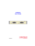
6H258-17 and 6H259-17 SmartSwitch 6000 Interface Modules Installation User’s Guide 9033381 Only qualified personnel should perform installation procedures. NOTICE Cabletron Systems reserves the right to make changes in specifications and other information contained in this document without prior notice. The reader should in all cases consult Cabletron Systems to determine whether any such changes have been made. The hardware, firmware, or software described in this manual is subject to change without notice. IN NO EVENT SHALL CABLETRON SYSTEMS BE LIABLE FOR ANY INCIDENTAL, INDIRECT, SPECIAL, OR CONSEQUENTIAL DAMAGES WHATSOEVER (INCLUDING BUT NOT LIMITED TO LOST PROFITS) ARISING OUT OF OR RELATED TO THIS MANUAL OR THE INFORMATION CONTAINED IN IT, EVEN IF CABLETRON SYSTEMS HAS BEEN ADVISED OF, KNOWN, OR SHOULD HAVE KNOWN, THE POSSIBILITY OF SUCH DAMAGES. Cabletron Systems, Inc. 35 Industrial Way Rochester, NH 03866-5005 2000 by Cabletron Systems, Inc. All Rights Reserved Printed in the United States of America Order Number: 9033381 January 2000 Cabletron Systems, QuickSET, SecureFast, and LANVIEW are registered trademarks and SmartSwitch is a trademark of Cabletron Systems, Inc. All other product names mentioned in this manual may be trademarks or registered trademarks of their respective companies. i FCC NOTICE This device complies with Part 15 of the FCC rules. Operation is subject to the following two conditions: (1) this device may not cause harmful interference, and (2) this device must accept any interference received, including interference that may cause undesired operation. NOTE: This equipment has been tested and found to comply with the limits for a Class A digital device, pursuant to Part 15 of the FCC rules. These limits are designed to provide reasonable protection against harmful interference when the equipment is operated in a commercial environment. This equipment uses, generates, and can radiate radio frequency energy and if not installed in accordance with the operator’s manual, may cause harmful interference to radio communications. Operation of this equipment in a residential area is likely to cause interference in which case the user will be required to correct the interference at his own expense. WARNING: Changes or modifications made to this device which are not expressly approved by the party responsible for compliance could void the user’s authority to operate the equipment. INDUSTRY CANADA NOTICE This digital apparatus does not exceed the Class A limits for radio noise emissions from digital apparatus set out in the Radio Interference Regulations of the Canadian Department of Communications. Le présent appareil numérique n’émet pas de bruits radioélectriques dépassant les limites applicables aux appareils numériques de la class A prescrites dans le Règlement sur le brouillage radioélectrique édicté par le ministère des Communications du Canada. VCCI NOTICE This is a Class A product based on the standard of the Voluntary Control Council for Interference by Information Technology Equipment (VCCI). If this equipment is used in a domestic environment, radio disturbance may arise. When such trouble occurs, the user may be required to take corrective actions. ii CABLETRON SYSTEMS, INC. PROGRAM LICENSE AGREEMENT IMPORTANT:THIS LICENSE APPLIES FOR USE OF PRODUCT IN THE FOLLOWING GEOGRAPHICAL REGIONS: CANADA MEXICO CENTRAL AMERICA SOUTH AMERICA BEFORE OPENING OR UTILIZING THE ENCLOSED PRODUCT, CAREFULLY READ THIS LICENSE AGREEMENT. This document is an agreement (“Agreement”) between You, the end user, and Cabletron Systems, Inc. (“Cabletron”) that sets forth your rights and obligations with respect to the Cabletron software program (“Program”) in the package. The Program may be contained in firmware, chips or other media. UTILIZING THE ENCLOSED PRODUCT, YOU ARE AGREEING TO BECOME BOUND BY THE TERMS OF THIS AGREEMENT, WHICH INCLUDES THE LICENSE AND THE LIMITATION OF WARRANTY AND DISCLAIMER OF LIABILITY. IF YOU DO NOT AGREE TO THE TERMS OF THIS AGREEMENT, RETURN THE UNOPENED PRODUCT TO CABLETRON OR YOUR DEALER, IF ANY, WITHIN TEN (10) DAYS FOLLOWING THE DATE OF RECEIPT FOR A FULL REFUND. IF YOU HAVE ANY QUESTIONS ABOUT THIS AGREEMENT, CONTACT CABLETRON SYSTEMS +1- 603-332-9400. Attn: Legal Department. 1. LICENSE. You have the right to use only the one (1) copy of the Program provided in this package subject to the terms and conditions of this License Agreement. You may not copy, reproduce or transmit any part of the Program except as permitted by the Copyright Act of the United States or as authorized in writing by Cabletron. 2. OTHER RESTRICTIONS. You may not reverse engineer, decompile, or disassemble the Program. 3. APPLICABLE LAW. This License Agreement shall be interpreted and governed under the laws and in the state and federal courts of New Hampshire. You accept the personal jurisdiction and venue of the New Hampshire courts. 4. EXPORT REQUIREMENTS. You understand that Cabletron and its Affiliates are subject to regulation by agencies of the U.S. Government, including the U.S. Department of Commerce, which prohibit export or diversion of certain technical products to certain countries, unless a license to export the product is obtained from the U.S. Government or an exception from obtaining such license may be relied upon by the exporting party. If the Program is exported from the United States pursuant to the License Exception CIV under the U.S. Export Administration Regulations, You agree that You are a civil end user of the Program and agree that You will use the Program for civil end uses only and not for military purposes. iii If the Program is exported from the United States pursuant to the License Exception TSR under the U.S. Export Administration Regulations, in addition to the restriction on transfer set forth in Sections 1 or 2 of this Agreement, You agree not to (i) reexport or release the Program, the source code for the Program or technology to a national of a country in Country Groups D:1 or E:2 (Albania, Armenia, Azerbaijan, Belarus, Bulgaria, Cambodia, Cuba, Estonia, Georgia, Iraq, Kazakhstan, Kyrgyzstan, Laos, Latvia, Libya, Lithuania, Moldova, North Korea, the People’s Republic of China, Romania, Russia, Rwanda, Tajikistan, Turkmenistan, Ukraine, Uzbekistan, Vietnam, or such other countries as may be designated by the United States Government), (ii) export to Country Groups D:1 or E:2 (as defined herein) the direct product of the Program or the technology, if such foreign produced direct product is subject to national security controls as identified on the U.S. Commerce Control List, or (iii) if the direct product of the technology is a complete plant o r any major component of a plant, export to Country Groups D:1 or E:2 the direct product of the plant or a major component thereof, if such foreign produced direct product is subject to national security controls as identified on the U.S. Commerce Control List or is subject to State Department controls under the U.S. Munitions List. 5. UNITED STATES GOVERNMENT RESTRICTED RIGHTS. The enclosed Product (i) was developed solely at private expense; (ii) contains “restricted computer software” submitted with restricted rights in accordance with section 52.227-19 (a) through (d) of the Commercial Computer Software-Restricted Rights Clause and its successors, and (iii) in all respects is proprietary data belonging to Cabletron and/or its suppliers. For Department of Defense units, the Product is considered commercial computer software in accordance with DFARS section 227.7202-3 and its successors, and use, duplication, or disclosure by the Government is subject to restrictions set forth herein. 6. EXCLUSION OF WARRANTY. Except as may be specifically provided by Cabletron in writing, Cabletron makes no warranty, expressed or implied, concerning the Program (including its documentation and media). CABLETRON DISCLAIMS ALL WARRANTIES, OTHER THAN THOSE SUPPLIED TO YOU BY CABLETRON IN WRITING, EITHER EXPRESS OR IMPLIED, INCLUDING BUT NOT LIMITED TO IMPLIED WARRANTIES OF MERCHANTABILITY AND FITNESS FOR A PARTICULAR PURPOSE, WITH RESPECT TO THE PROGRAM, THE ACCOMPANYING WRITTEN MATERIALS, AND ANY ACCOMPANYING HARDWARE. 7. NO LIABILITY FOR CONSEQUENTIAL DAMAGES. IN NO EVENT SHALL CABLETRON OR ITS SUPPLIERS BE LIABLE FOR ANY DAMAGES WHATSOEVER (INCLUDING, WITHOUT LIMITATION, DAMAGES FOR LOSS OF BUSINESS, PROFITS, BUSINESS INTERRUPTION, LOSS OF BUSINESS INFORMATION, SPECIAL, INCIDENTAL, CONSEQUENTIAL, OR RELIANCE DAMAGES, OR OTHER LOSS) ARISING OUT OF THE USE OR INABILITY TO USE THIS CABLETRON PRODUCT, EVEN IF CABLETRON HAS BEEN ADVISED OF THE POSSIBILITY OF SUCH DAMAGES. BECAUSE SOME STATES DO NOT ALLOW THE EXCLUSION OR LIMITATION OF LIABILITY FOR CONSEQUENTIAL OR INCIDENTAL DAMAGES, OR IN THE DURATION OR LIMITATION OF IMPLIED WARRANTIES IN SOME INSTANCES, THE ABOVE LIMITATION AND EXCLUSIONS MAY NOT APPLY TO YOU. iv CABLETRON SYSTEMS SALES AND SERVICE, INC. PROGRAM LICENSE AGREEMENT IMPORTANT: THIS LICENSE APPLIES FOR USE OF PRODUCT IN THE UNITED STATES OF AMERICA AND BY UNITED STATES OF AMERICA GOVERNMENT END USERS. BEFORE OPENING OR UTILIZING THE ENCLOSED PRODUCT, CAREFULLY READ THIS LICENSE AGREEMENT. This document is an agreement (“Agreement”) between You, the end user, and Cabletron Systems Sales and Service, Inc. (“Cabletron”) that sets forth your rights and obligations with respect to the Cabletron software program (“Program”) in the package. The Program may be contained in firmware, chips or other media. UTILIZING THE ENCLOSED PRODUCT, YOU ARE AGREEING TO BECOME BOUND BY THE TERMS OF THIS AGREEMENT, WHICH INCLUDES THE LICENSE AND THE LIMITATION OF WARRANTY AND DISCLAIMER OF LIABILITY. IF YOU DO NOT AGREE TO THE TERMS OF THIS AGREEMENT, RETURN THE UNOPENED PRODUCT TO CABLETRON OR YOUR DEALER, IF ANY, WITHIN TEN (10) DAYS FOLLOWING THE DATE OF RECEIPT FOR A FULL REFUND. IF YOU HAVE ANY QUESTIONS ABOUT THIS AGREEMENT, CONTACT CABLETRON SYSTEMS +1-603-332-9400. Attn: Legal Department. 1. LICENSE. You have the right to use only the one (1) copy of the Program provided in this package subject to the terms and conditions of this License Agreement. You may not copy, reproduce or transmit any part of the Program except as permitted by the Copyright Act of the United States or as authorized in writing by Cabletron. 2. OTHER RESTRICTIONS. You may not reverse engineer, decompile, or disassemble the Program. 3. APPLICABLE LAW. This License Agreement shall be interpreted and governed under the laws and in the state and federal courts of New Hampshire. You accept the personal jurisdiction and venue of the New Hampshire courts. 4. EXPORT REQUIREMENTS. You understand that Cabletron and its Affiliates are subject to regulation by agencies of the U.S. Government, including the U.S. Department of Commerce, which prohibit export or diversion of certain technical products to certain countries, unless a license to export the product is obtained from the U.S. Government or an exception from obtaining such license may be relied upon by the exporting party. If the Program is exported from the United States pursuant to the License Exception CIV under the U.S. Export Administration Regulations, You agree that You are a civil end user of the Program and agree that You will use the Program for civil end uses only and not for military purposes. If the Program is exported from the United States pursuant to the License Exception TSR under the U.S. Export Administration Regulations, in addition to the restriction on transfer set forth in Sections 1 or 2 of this Agreement, You agree not to (i) reexport or release the Program, the source code for the Program or technology to a national of a country in Country Groups D:1 or E:2 (Albania, Armenia, Azerbaijan, Belarus, Bulgaria, Cambodia, Cuba, Estonia, Georgia, Iraq, Kazakhstan, Kyrgyzstan, Laos, Latvia, Libya, Lithuania, Moldova, North Korea, the People’s Republic of China, Romania, Russia, Rwanda, Tajikistan, Turkmenistan, Ukraine, Uzbekistan, Vietnam, or such other countries as may be designated by the United States Government), (ii) export to Country Groups D:1 or E:2 (as defined herein) the direct product of the Program or the technology, if such foreign produced direct product is subject to national security controls as identified on the U.S. Commerce Control List, or (iii) if the direct product of the technology is a complete plant o r any major component of a plant, export to Country Groups D:1 or E:2 the direct product of the plant or a major component thereof, if such foreign produced direct product is subject to national security controls as identified on the U.S. Commerce Control List or is subject to State Department controls under the U.S. Munitions List. v 5. UNITED STATES GOVERNMENT RESTRICTED RIGHTS. The enclosed Product (i) was developed solely at private expense; (ii) contains “restricted computer software” submitted with restricted rights in accordance with section 52.227-19 (a) through (d) of the Commercial Computer Software-Restricted Rights Clause and its successors, and (iii) in all respects is proprietary data belonging to Cabletron and/or its suppliers. For Department of Defense units, the Product is considered commercial computer software in accordance with DFARS section 227.7202-3 and its successors, and use, duplication, or disclosure by the Government is subject to restrictions set forth herein. 6. EXCLUSION OF WARRANTY. Except as may be specifically provided by Cabletron in writing, Cabletron makes no warranty, expressed or implied, concerning the Program (including its documentation and media). CABLETRON DISCLAIMS ALL WARRANTIES, OTHER THAN THOSE SUPPLIED TO YOU BY CABLETRON IN WRITING, EITHER EXPRESS OR IMPLIED, INCLUDING BUT NOT LIMITED TO IMPLIED WARRANTIES OF MERCHANTABILITY AND FITNESS FOR A PARTICULAR PURPOSE, WITH RESPECT TO THE PROGRAM, THE ACCOMPANYING WRITTEN MATERIALS, AND ANY ACCOMPANYING HARDWARE. 7. NO LIABILITY FOR CONSEQUENTIAL DAMAGES. IN NO EVENT SHALL CABLETRON OR ITS SUPPLIERS BE LIABLE FOR ANY DAMAGES WHATSOEVER (INCLUDING, WITHOUT LIMITATION, DAMAGES FOR LOSS OF BUSINESS, PROFITS, BUSINESS INTERRUPTION, LOSS OF BUSINESS INFORMATION, SPECIAL, INCIDENTAL, CONSEQUENTIAL, OR RELIANCE DAMAGES, OR OTHER LOSS) ARISING OUT OF THE USE OR INABILITY TO USE THIS CABLETRON PRODUCT, EVEN IF CABLETRON HAS BEEN ADVISED OF THE POSSIBILITY OF SUCH DAMAGES. BECAUSE SOME STATES DO NOT ALLOW THE EXCLUSION OR LIMITATION OF LIABILITY FOR CONSEQUENTIAL OR INCIDENTAL DAMAGES, OR IN THE DURATION OR LIMITATION OF IMPLIED WARRANTIES IN SOME INSTANCES, THE ABOVE LIMITATION AND EXCLUSIONS MAY NOT APPLY TO YOU. vi CABLETRON SYSTEMS LIMITED PROGRAM LICENSE AGREEMENT IMPORTANT: THIS LICENSE APPLIES FOR THE USE OF THE PRODUCT IN THE FOLLOWING GEOGRAPHICAL REGIONS: EUROPE MIDDLE EAST AFRICA ASIA AUSTRALIA PACIFIC RIM BEFORE OPENING OR UTILIZING THE ENCLOSED PRODUCT, CAREFULLY READ THIS LICENSE AGREEMENT. This document is an agreement (“Agreement”) between You, the end user, and Cabletron Systems Limited (“Cabletron”) that sets forth your rights and obligations with respect to the Cabletron software program (“Program”) in the package. The Program may be contained in firmware, chips or other media. UTILIZING THE ENCLOSED PRODUCT, YOU ARE AGREEING TO BECOME BOUND BY THE TERMS OF THIS AGREEMENT, WHICH INCLUDES THE LICENSE AND THE LIMITATION OF WARRANTY AND DISCLAIMER OF LIABILITY. IF YOU DO NOT AGREE TO THE TERMS OF THIS AGREEMENT, RETURN THE UNOPENED PRODUCT TO CABLETRON OR YOUR DEALER, IF ANY, WITHIN TEN (10) DAYS FOLLOWING THE DATE OF RECEIPT FOR A FULL REFUND. IF YOU HAVE ANY QUESTIONS ABOUT THIS AGREEMENT, CONTACT CABLETRON SYSTEMS +1-603-332-9400. Attn: Legal Department. 1. LICENSE. You have the right to use only the one (1) copy of the Program provided in this package subject to the terms and conditions of this License Agreement. You may not copy, reproduce or transmit any part of the Program except as permitted by the Copyright Act of the United States or as authorized in writing by Cabletron. 2. OTHER RESTRICTIONS. You may not reverse engineer, decompile, or disassemble the Program. 3. APPLICABLE LAW. This License Agreement shall be governed in accordance with English law. The English courts shall have exclusive jurisdiction in the event of any disputes. 4. EXPORT REQUIREMENTS. You understand that Cabletron and its Affiliates are subject to regulation by agencies of the U.S. Government, including the U.S. Department of Commerce, which prohibit export or diversion of certain technical products to certain countries, unless a license to export the product is obtained from the U.S. Government or an exception from obtaining such license may be relied upon by the exporting party. If the Program is exported from the United States pursuant to the License Exception CIV under the U.S. Export Administration Regulations, You agree that You are a civil end user of the Program and agree that You will use the Program for civil end uses only and not for military purposes. vii If the Program is exported from the United States pursuant to the License Exception TSR under the U.S. Export Administration Regulations, in addition to the restriction on transfer set forth in Sections 1 or 2 of this Agreement, You agree not to (i) reexport or release the Program, the source code for the Program or technology to a national of a country in Country Groups D:1 or E:2 (Albania, Armenia, Azerbaijan, Belarus, Bulgaria, Cambodia, Cuba, Estonia, Georgia, Iraq, Kazakhstan, Kyrgyzstan, Laos, Latvia, Libya, Lithuania, Moldova, North Korea, the People’s Republic of China, Romania, Russia, Rwanda, Tajikistan, Turkmenistan, Ukraine, Uzbekistan, Vietnam, or such other countries as may be designated by the United States Government), (ii) export to Country Groups D:1 or E:2 (as defined herein) the direct product of the Program or the technology, if such foreign produced direct product is subject to national security controls as identified on the U.S. Commerce Control List, or (iii) if the direct product of the technology is a complete plant o r any major component of a plant, export to Country Groups D:1 or E:2 the direct product of the plant or a major component thereof, if such foreign produced direct product is subject to national security controls as identified on the U.S. Commerce Control List or is subject to State Department controls under the U.S. Munitions List. 5. UNITED STATES GOVERNMENT RESTRICTED RIGHTS. The enclosed Product (i) was developed solely at private expense; (ii) contains “restricted computer software” submitted with restricted rights in accordance with section 52.227-19 (a) through (d) of the Commercial Computer Software-Restricted Rights Clause and its successors, and (iii) in all respects is proprietary data belonging to Cabletron and/or its suppliers. For Department of Defense units, the Product is considered commercial computer software in accordance with DFARS section 227.7202-3 and its successors, and use, duplication, or disclosure by the Government is subject to restrictions set forth herein. 6. EXCLUSION OF WARRANTY. Except as may be specifically provided by Cabletron in writing, Cabletron makes no warranty, expressed or implied, concerning the Program (including its documentation and media). CABLETRON DISCLAIMS ALL WARRANTIES, OTHER THAN THOSE SUPPLIED TO YOU BY CABLETRON IN WRITING, EITHER EXPRESS OR IMPLIED, INCLUDING BUT NOT LIMITED TO IMPLIED WARRANTIES OF MERCHANTABILITY AND FITNESS FOR A PARTICULAR PURPOSE, WITH RESPECT TO THE PROGRAM, THE ACCOMPANYING WRITTEN MATERIALS, AND ANY ACCOMPANYING HARDWARE. 7. NO LIABILITY FOR CONSEQUENTIAL DAMAGES. IN NO EVENT SHALL CABLETRON OR ITS SUPPLIERS BE LIABLE FOR ANY DAMAGES WHATSOEVER (INCLUDING, WITHOUT LIMITATION, DAMAGES FOR LOSS OF BUSINESS, PROFITS, BUSINESS INTERRUPTION, LOSS OF BUSINESS INFORMATION, SPECIAL, INCIDENTAL, CONSEQUENTIAL, OR RELIANCE DAMAGES, OR OTHER LOSS) ARISING OUT OF THE USE OR INABILITY TO USE THIS CABLETRON PRODUCT, EVEN IF CABLETRON HAS BEEN ADVISED OF THE POSSIBILITY OF SUCH DAMAGES. BECAUSE SOME STATES DO NOT ALLOW THE EXCLUSION OR LIMITATION OF LIABILITY FOR CONSEQUENTIAL OR INCIDENTAL DAMAGES, OR IN THE DURATION OR LIMITATION OF IMPLIED WARRANTIES IN SOME INSTANCES, THE ABOVE LIMITATION AND EXCLUSIONS MAY NOT APPLY TO YOU. viii SAFETY INFORMATION CLASS 1 LASER TRANSCEIVERS THE GPIM-01 AND GPIM-09 GIGABIT ETHERNET MODULES USE CLASS 1 LASER TRANSCEIVERS. READ THE FOLLOWING SAFETY INFORMATION BEFORE INSTALLING OR OPERATING THESE MODULES. The Class 1 laser transceivers use an optical feedback loop to maintain Class 1 operation limits. This control loop eliminates the need for maintenance checks or adjustments. The output is factory set, and does not allow any user adjustment. Class 1 Laser transceivers comply with the following safety standards: • 21 CFR 1040.10 and 1040.11 U.S. Department of Health and Human Services (FDA). • IEC Publication 825 (International Electrotechnical Commission). • CENELEC EN 60825 (European Committee for Electrotechnical Standardization). When operating within their performance limitations, laser transceiver output meets the Class 1 accessible emission limit of all three standards. Class 1 levels of laser radiation are not considered hazardous. SAFETY INFORMATION CLASS 1 LASER TRANSCEIVERS LASER RADIATION AND CONNECTORS When the connector is in place, all laser radiation remains within the fiber. The maximum amount of radiant power exiting the fiber (under normal conditions) is -12.6 dBm or 55 x 10-6 watts. Removing the optical connector from the transceiver allows laser radiation to emit directly from the optical port. The maximum radiance from the optical port (under worst case conditions) is 0.8 W cm-2 or 8 x 10³ W m2 sr-1. Do not use optical instruments to view the laser output. The use of optical instruments to view laser output increases eye hazard. When viewing the output optical port, power must be removed from the network adapter. ix DECLARATION OF CONFORMITY Application of Council Directive(s): Manufacturer’s Name: Manufacturer’s Address: 89/336/EEC 73/23/EEC Cabletron Systems, Inc. 35 Industrial Way PO Box 5005 Rochester, NH 03867 European Representative Name: Mr. J. Solari European Representative Address: Cabletron Systems Limited Nexus House, Newbury Business Park London Road, Newbury Berkshire RG14 2PZ, England Conformance to Directive(s)/Product Standards: Equipment Type/Environment: EC Directive 89/336/EEC EC Directive 73/23/EEC EN 55022 EN 50082-1 EN 60950 Networking Equipment, for use in a Commercial or Light Industrial Environment. We the undersigned, hereby declare, under our sole responsibility, that the equipment packaged with this notice conforms to the above directives. x Manufacturer Legal Representative in Europe Mr. Ronald Fotino ___________________________________ Full Name Mr. J. Solari ___________________________________ Full Name Compliance Engineering Manager ___________________________________ Title Managing Director - E.M.E.A. ___________________________________ Title Rochester, NH, USA ___________________________________ Location Newbury, Berkshire, England ___________________________________ Location Contents Figures............................................................................................................................ xiii Tables ............................................................................................................................. xiv ABOUT THIS GUIDE Using This Guide............................................................................................................xv Structure of This Guide .................................................................................................xvi Related Manuals .......................................................................................................... xvii Document Conventions............................................................................................... xviii 1 INTRODUCTION 1.1 1.2 Overview ......................................................................................................... 1-1 1.1.1 Connectivity........................................................................................ 1-3 1.1.2 Runtime IP Address Discovery .......................................................... 1-3 1.1.3 Full Duplex Switched Ethernet ........................................................... 1-3 1.1.4 SmartTrunk ........................................................................................ 1-4 1.1.5 Remote Monitoring (RMON) .............................................................. 1-4 1.1.6 Broadcast Suppression ...................................................................... 1-4 1.1.7 Port/VLAN Redirect Functions ........................................................... 1-4 1.1.8 Rate Limiting ...................................................................................... 1-5 1.1.9 GARP Switch Operation..................................................................... 1-5 1.1.10 Flow Control ....................................................................................... 1-6 1.1.11 802.1 Port Priority .............................................................................. 1-6 1.1.12 Management ...................................................................................... 1-6 1.1.13 Switching Options .............................................................................. 1-7 1.1.14 Distributed Chassis Management ...................................................... 1-7 1.1.15 Optional HSIMs and VHSIMs............................................................. 1-7 1.1.16 Standards Compatibility ..................................................................... 1-7 1.1.17 LANVIEW Diagnostic LEDs ............................................................... 1-8 1.1.18 Year 2000 Compliance....................................................................... 1-8 Getting Help .................................................................................................... 1-8 xi 2 NETWORK REQUIREMENTS 2.1 2.2 3 INSTALLATION 3.1 3.2 3.3 3.4 3.5 4 B.3 xii Module Specifications .....................................................................................A-1 Physical Properties .........................................................................................A-1 Environmental Requirements..........................................................................A-2 Input/Output Ports ...........................................................................................A-2 COM Port Pinout Assignments .......................................................................A-2 Regulatory Compliance...................................................................................A-3 SWITCH SETTINGS, UPGRADES, AND INSTALLATIONS B.1 B.2 INDEX Using LANVIEW.............................................................................................. 4-1 Troubleshooting Checklist............................................................................... 4-5 Using the RESET Button............................................................................... 4-10 SPECIFICATIONS A.1 A.2 A.3 A.4 A.5 A.6 B Unpacking the SmartSwitch ............................................................................ 3-1 Installing Options............................................................................................. 3-2 Installing the SmartSwitch into the 6C105 Chassis......................................... 3-2 Connecting to the Network.............................................................................. 3-4 Completing the Installation.............................................................................. 3-6 TROUBLESHOOTING 4.1 4.2 4.3 A 100BASE-FX Network..................................................................................... 2-1 2.1.1 Multimode Fiber Optic Cabling ........................................................... 2-1 2.1.2 Single Mode Fiber Optic Cabling ....................................................... 2-2 SmartTrunk...................................................................................................... 2-2 Setting the Mode Switches..............................................................................B-1 SIMM Upgrade ................................................................................................B-3 B.2.1 Locating SIMMs .................................................................................B-3 B.2.2 Installing the DRAM SIMM .................................................................B-4 Installing Optional High Speed Interface Modules ..........................................B-5 Figures Figure 1-1 3-1 3-2 4-1 4-2 B-1 B-2 B-3 B-4 Page The SmartSwitch ............................................................................................................. 1-2 Installing an Interface Module ......................................................................................... 3-3 Connecting a Fiber Optic Segment to the SmartSwitch .................................................. 3-5 LANVIEW LEDs .............................................................................................................. 4-2 RESET Button ............................................................................................................... 4-10 Module Mode Switch Location/Component Layout .........................................................B-2 SIMM Slot Locations .......................................................................................................B-4 Installing the DRAM.........................................................................................................B-5 HSIM and VHSIM Connector Locations ..........................................................................B-6 xiii Tables Table 3-1 4-1 4-2 4-3 4-4 4-5 4-6 A-1 xiv Page Contents of SmartSwitch Shipping Container.............................................................. 3-1 LANVIEW LEDs ........................................................................................................... 4-3 Fault Identification........................................................................................................ 4-5 Power System Troubleshooting ................................................................................... 4-6 Firmware Troubleshooting ........................................................................................... 4-7 Management System Troubleshooting ........................................................................ 4-8 Device Setup Troubleshooting..................................................................................... 4-9 COM Port Pin Assignments......................................................................................... A-2 About This Guide Welcome to the Cabletron Systems 6H258-17 and 6H259-17 SmartSwitch 6000 Interface Modules User’s Guide. This guide describes the 6H258-17 and 6H259-17 Interface Modules and provides information concerning network requirements, installation and troubleshooting. For information about how to use Local Management to configure and manage the SmartSwitch series, refer to the SmartSwitch Series 6H202, 6H203, 6H252, 6H253, 6H258, 6H259, 6H262, 6E233, and 6E253 Local Management User’s Guide. Important Notice Depending on the firmware version used in the 6H258-17 and 6H259-17, some features described in this document may not be supported. Refer to the Release Notes shipped with the device to determine which features are supported. USING THIS GUIDE Read through this guide completely to understand the 6H258-17 and 6H259-17 module features, capabilities, and Local Management functions. A general working knowledge of Fast Ethernet and IEEE 802.3 type data communications networks and their physical layer components is helpful when using these devices. NOTE This module has two versions, the multimode fiber version (6H258-17), and the single mode fiber version (6H259-17). Since the only difference between the two versions is the type of fiber used in the network connection, the two versions will be referred to as the SmartSwitch in the rest of this document. When information is specific to a version, that version will be referred to by its name. The term “module” may also be used to refer to either of the versions. xv Structure of This Guide STRUCTURE OF THIS GUIDE This guide is organized as follows: This About This Guide preface provides preliminary information that will aid in using this manual, lists technology and user guides that may help the user set up and manage the SmartSwitch, and gives instructions on how to get help from Cabletron Systems. Chapter 1, Introduction, describes the features of the SmartSwitch. Chapter 2, Network Requirements, outlines the network requirements that must be met before installing the SmartSwitch into the 6C105 SmartSwitch 6000 chassis. Chapter 3, Installation, provides instructions on how to install the module in the chassis and connect segments to the device. Chapter 4, Troubleshooting, details the SmartSwitch LANVIEW LEDs that enable quick diagnosis of network/operational problems. Appendix A, Specifications, contains information on functionality and operating specifications, connector pinouts, environmental requirements, and physical properties. Appendix B, Switch Settings, Upgrades, and Installations, describes setting the Mode Switches, and includes upgrade and installation information. xvi Related Manuals RELATED MANUALS The following manuals may help the user to setup and manage the SmartSwitch modules: • SmartSwitch Series 6H202, 6H203, 6H252, 6H253, 6H258, 6H259, 6H262, 6E233, and 6E253 Local Management User’s Guide • 6C105 SmartSwitch 6000 Overview and Setup Guide • Ethernet Technology Guide • Cabling Guide • 802.1Q VLAN User’s Guide • SmartTrunk User’s Guide The following manuals, as applicable, may help the user to set up and manage the SmartSwitches: • HSIM-A6DP User’s Guide • HSIM-F6 User’s Guide • HSIM-FE6 User’s Guide • HSIM-W6 User’s Guide • HSIM-W84 User’s Guide • HSIM-W87 User’s Guide • HSIM-G01/G09 User’s Guide • VHSIM-G6 User’s Guide • VHSIM-A6DP User’s Guide • WAN Series Local Management User’s Guide • VHSIM-A6DP User’s Guide The HSIM-W6 Installation Guide, the HSIM-W84 Installation Guide, and the WAN Series Local Management User’s Guide are included on the QuickSET CD-ROM and, along with the other manuals referenced above, can be obtained on the World Wide Web in Adobe Acrobat Portable Document Format (PDF) at the following site: http://www.cabletron.com/ NOTE All documentation for Cabletron Systems SecureFast VLAN Manager software can be found on the VLAN Manager CD-ROM. xvii Document Conventions DOCUMENT CONVENTIONS The following conventions are used throughout this document: NOTE Note symbol. Calls the reader’s attention to any item of information that may be of special importance. Tip symbol. Conveys helpful hints concerning procedures or actions. TIP ! Caution symbol. Contains information essential to avoid damage to the equipment. CAUTION Electrical Hazard Warning symbol. Warns against an action that could result in personal injury or death due to an electrical hazard. xviii 1 Introduction This chapter introduces the 6H258-17 and 6H259-17 SmartSwitch 6000 interface modules and provides information about how to obtain additional support from Cabletron Systems. Important Notice Depending on the firmware version used in the SmartSwitches, some features described in this document may not be supported. Refer to the Release Notes shipped with the device to determine which features are supported. 1.1 OVERVIEW The SmartSwitch, shown in Figure 1-1, is a Fast Ethernet interface module for the Cabletron Systems 6C105 chassis. The SmartSwitch has 16 MT-RJ fiber optic switched ports and 1 slot for an optional High Speed Interface Module (HSIM) or Very High Speed Interface Module (VHSIM). The 6H258-17 uses multimode fiber optic cable for the network connections, while the 6H259-17 uses single mode fiber optic cable. The physical connectors look the same. The SmartSwitches can be used to connect individual high-bandwidth user devices, such as workstations, or to provide a central switching point for multiple 100 Mbps Fast Ethernet segments. The optional HSIMs provide one or more high speed uplinks to other networking technologies such as Gigabit Ethernet, Fast Ethernet, Fiber Distributed Data Interface (FDDI), Wide Area Network (WAN) and Asynchronous Transfer Mode (ATM). Some HSIMs also provide additional Fast Ethernet ports in varying media types. The optional VHSIMs provide very high speed uplinks to networking technologies such as ATM and Gigabit Ethernet. The SmartSwitch ports can be configured to control frame traffic several ways, including prioritizing traffic flow according to protocol type. The SmartSwitches can also be configured to establish Virtual Local Area Networks (VLANs) and control the flow of frames associated with each VLAN according to priority and Ether type. Detailed information about VLANs is provided in the Local Management User’s Guide. Introduction 1-1 Overview Reset COM Port CPU LED Network Ports 1-16 Port Status LEDs VHSIM/HSIM Slot Figure 1-1 1-2 Introduction The SmartSwitch Overview 1.1.1 Connectivity The SmartSwitch modules connects to Fast Ethernet networks or workstations through the MT-RJ fiber optic ports on the front panel for 100 Mbps with duplex capability. These ports are in full compliance with the optical performance requirements of 100BASE-FX version of IEEE 802.3u. The 6H258-17 ports support multimode fiber optic cables up to 2 km. The 6H259-17 ports support single mode fiber optic cables up to 15 km. SmartSwitches have a slot for an optional HSIM or VHSIM to provide additional connectivity to various networking technologies. 1.1.2 Runtime IP Address Discovery This feature enables the module to automatically accept an IP address from a Boot Strap Protocol (BootP) server on the network into NVRAM without requiring a user to enter an IP address through Local Management. When the module is connected to the network and powered up, Runtime IP Address Discovery (RAD) checks the module for an IP address. If one has not yet been assigned (module and 6C105 chassis IP address set to 0.0.0.0), RAD checks to see if any of the module interfaces have a link. If so, RAD sends out Reverse Address Resolution Protocol (RARP) and BootP requests to obtain an IP address from a RARP or BootP server on the network. The RAD requests start at an interval of one per second. The interval then doubles after every transmission until an interval of 300 seconds is reached. At this point, the interval remains at 300 seconds. The RAD requests continue until an IP address is received from a RARP or BootP server, or an IP address is entered using Local Management. The module will reboot after RAD is successful. NOTE 1.1.3 Full Duplex Switched Ethernet Each switched Fast Ethernet port on the SmartSwitch supports 100 Mbps operation and can be configured to operate in Full Duplex Switched Ethernet (FDSE) mode. FDSE allows each port to provide up to 200 Mbps of bandwidth. Introduction 1-3 Overview 1.1.4 SmartTrunk SmartTrunk, also referred to as SmartTrunking, is Cabletron Systems’ terminology for load balancing or load sharing. SmartTrunk technology provides an easy-to-implement mechanism to group, or aggregate, multiple links of any technology together to scale the backbone bandwidth beyond the limitations of a single link. All links are user-configurable so administrators can scale the backbone bandwidth by adding SmartTrunk links. The benefits of SmartTrunking include the following: • All purchased bandwidth is used. • Distributed, resilient links increase reliability and performance. • Multiple technologies are supported within a single trunk for maximum flexibility. NOTE 1.1.5 For information on SmartTrunk configuration, refer to the Cabletron Systems SmartTrunk User’s Guide. Remote Monitoring (RMON) The SmartSwitch modules support all nine Ethernet RMON groups. The Statistics, Alarms, Events and History groups are enabled on all ports by default. Cabletron Systems RMON Actions is a vendor-specific extension of RMON and provides the ability to set an “Action” on any SNMP MIB variable. The Action can be triggered by setting an RMON Event and/or Alarm. An example of an Action would be to turn off a MIB-2 interface if a broadcast threshold is crossed. 1.1.6 Broadcast Suppression Broadcast Suppression enables a user to set a desired limit of receive broadcast frames per port/per second to be forwarded out the other ports on the module up to the set limit. Any broadcast frames above this specified limit are dropped. In the event that broadcast frames are being suppressed, multicast and unicast frames continue to be switched. 1.1.7 Port/VLAN Redirect Functions The port redirect function, also referred to as “Port Mirroring,” is a troubleshooting tool used to map traffic from a single source port to a single destination port within the device. This feature allows frames, including those with errors, to be copied and sent to an analyzer or RMON probe. 1-4 Introduction Overview The analyzer or RMON probe will see the data as if it were directly connected to the LAN segment of the source port. The VLAN redirect function is similar to the port redirect function except that the frames received by the device are redirected to a designated destination port according to the VLAN classification of the frames received. The VLAN redirect function does not support redirecting errors, and is only supported when the device is operating as an 802.1Q switch. Multiple VLANs can be directed to the same ports. 1.1.8 Rate Limiting The Rate Limiting feature enables the SmartSwitch device to have control of traffic rates on a per-port, per-priority basis. The network administrator can configure a rate limit (from 100 kbps to 1 Gbps) for a given port with an associated list of IEEE 802.1p priorities (which can include one, some, or all of the eight priority levels defined in 802.1p). Each rate limit is specified as an inbound or an outbound limit. The combined rate of all traffic on the port that matches the listed priorities cannot exceed the programmed limit. If the rate exceeds the defined limit, frames are dropped until the rate falls below the limit. Administrators can configure up to four rate limit rules per port; however, each rule must not include conflicting 802.1p priority values. In order to control traffic inbound and outbound on the same port, two rate limit rules must be configured (one inbound and one outbound). Since the rate limiting operation occurs after the processing of the multi-layer classification rules, the two features can be combined to provide application-aware rate limiting. This traffic rate function is not supported on ports configured as SmartTrunk ports. NOTE For more information about the application of the Rate Limiting function, refer to the Local Management User’s Guide. 1.1.9 GARP Switch Operation Some or all ports on the switch may be activated to operate under the Generic Attribute Registration Protocol (GARP) applications, GARP VLAN Registration Protocol (GVRP) and/or GARP Multicast Registration Protocol (GMRP). GARP is a protocol, or set of rules, that outlines a mechanism for propagating the port state and/or user information throughout a bridged LAN to keep track of users and VLANs on the network fabric. MAC bridges and end users alike can take part in the registration and de-registration of GARP attributes such as VLAN and multicast group membership. For more details on how GVRP Introduction 1-5 Overview and GMRP handle frames under GARP, and how to configure the switch ports to take advantage of this operation, refer to Local Management User’s Guide. 1.1.10 Flow Control Flow control is a method of managing the flow of frames between two devices. It ensures that a transmitting device does not overwhelm a receiving device with data. This enables the receiving device to communicate with the transmitting device, and to have it pause its transmission while the receiving device processes the frames already received. Both devices must support the IEEE 802.3x standard for flow control to work. The SmartSwitch modules support the following two types of flow control: • frame based 802.3x • back pressure Frame based 802.3x flow control is supported on all Ethernet ports operating in the full duplex mode. Flow control can be enabled or disabled on a port-by-port basis. Back pressure flow control is supported on all Ethernet ports operating in the standard mode of operation. Flow control can be enabled or disabled on a port-by-port basis. 1.1.11 802.1 Port Priority IEEE 802.1 port priority is incorporated in the IEEE 802.1D standard. It is used to assign a default priority to the frames received without priority information in their tag header, to map prioritized frames to the appropriate transmit queues, and to prioritize frames according to protocol type. 1.1.12 Management Management of the SmartSwitch modules and 6C105 chassis is accomplished using the Local Management application or remote SNMP management stations. Local Management is accessible through the RS232 COM port on the front panel using a local VT100 terminal, or a remote VT100 terminal via a modem connection, and in-band via a Telnet connection. In-band remote management is possible through any SNMP compliant Network Management Software. Local Management, as described in your Local Management User’s Guide, provides the ability to manage the SmartSwitches and offers information for Ethernet HSIMs or VHSIMs. Local Management information for non-Ethernet HSIMs or VHSIMs is included in their respective user’s guide. For details on how to get manuals, refer to the Related Manuals section in the About This Guide section. 1-6 Introduction Overview 1.1.13 Switching Options SmartSwitches provide 802.1Q switching or SecureFast Switching Virtual Network Services between all of the front panel interfaces including any optional HSIM or VHSIM. In the 802.1Q mode (the default mode of operation), the switch functions as an 802.1D switch until VLANs are configured. SecureFast switching and IEEE 802.1Q switching allow migration to Virtual Network technologies without requiring the replacement of existing equipment. 1.1.14 Distributed Chassis Management From a management perspective, the 6C105 SmartSwitch 6000 chassis can be viewed as a single entity with a single IP address. Its systems management functions are distributed to all modules. The chassis can be managed using a single IP address, or the modules can be managed separately by individual IP addresses. When using a single IP address, system wide settings can be done from the chassis menu in Local Management, while module settings are done by selecting the specific module to be modified and changing the settings for that module. 1.1.15 Optional HSIMs and VHSIMs The SmartSwitches provide a slot for an optional High Speed Interface Module (HSIM) or Very High Speed Interface Module (VHSIM) for additional connectivity to various networking technologies. Any exceptions to the HSIMs and VHSIMs that operate in the SmartSwitch modules are listed in the Release Notes shipped with the SmartSwitch. 1.1.16 Standards Compatibility The SmartSwitch modules are fully compliant with the IEEE 802.3, 802.3x, 802.3u, 802.1D, and specifically 802.1Q standards. SmartSwitches provide IEEE 802.1D Spanning Tree Algorithm (STA) support to enhance the overall reliability of the network and protect against “loop” conditions. SmartSwitches support a wide variety of industry standard MIBs including RFC 1213 (MIB II), RFC 1757 (RMON), RFC 1493 (Bridge MIB), RFC 1354 (FIB MIB), and RFC 1190 (Path MTU Discovery). A full suite of Cabletron Systems Enterprise MIBs provide a wide array of statistical information to enhance troubleshooting. For information about how to extract and compile individual MIBs, contact Cabletron Systems. Introduction 1-7 Getting Help 1.1.17 LANVIEW Diagnostic LEDs LANVIEW diagnostic LEDs serve as an important troubleshooting aid by providing an easy way to observe the status of individual ports and overall network operations. 1.1.18 Year 2000 Compliance The SmartSwitch modules and 6C105 chassis have an internal clock that can maintain the time and date beyond the year 1999. 1.2 GETTING HELP For additional support related to this device or document, contact Cabletron Systems using one of the following methods: World Wide Web http://www.cabletron.com/ Phone (603) 332-9400 Internet mail [email protected] FTP Login ftp://ftp.cabletron.com/ anonymous Password your email address To send comments or suggestions concerning this document, contact the Cabletron Systems Technical Writing Department via the following email address: [email protected] Make sure to include the document Part Number in the email message. Before calling Cabletron Systems, have the following information ready: • Your Cabletron Systems service contract number • A description of the failure • A description of any action(s) already taken to resolve the problem (e.g., changing mode switches, rebooting the unit, etc.) • The serial and revision numbers of all involved Cabletron Systems products in the network • A description of your network environment (layout, cable type, etc.) • Network load and frame size at the time of trouble (if known) • The device history (i.e., have you returned the device before, is this a recurring problem, etc.) • Any previous Return Material Authorization (RMA) numbers 1-8 Introduction 2 Network Requirements Before installing the SmartSwitch modules, review the requirements and specifications referred to in this chapter concerning the following: • 100BASE-FX Network (Section 2.1) • SmartTrunk (Section 2.2) The network installation must meet the guidelines in this chapter and in the documents referenced in this chapter to ensure satisfactory performance of the equipment. Failure to follow the guidelines may produce poor network performance. 2.1 100BASE-FX NETWORK When connecting a 100BASE-FX segment to any of the SmartSwitch ports, ensure that the network meets the optical performance requirements for 100BASE-FX IEEE 802.3u standard. One module, the 6H258-17, is made specifically for multimode fiber optic cable and the other, the 6H259-17, is made specifically for single mode fiber optic cable. The two modules cannot be used interchangeably with respect to multimode or single mode fiber optic cable. Refer to Section 2.1.1 for information on multimode cabling, and Section 2.1.2 for information on single mode cabling for these modules. 2.1.1 Multimode Fiber Optic Cabling The 6H258-17 fixed ports use LEDs to support multimode fiber optic cables at the 1300 nm wavelength, at lengths of up to 2 km. Refer to the Cabletron Systems Cabling Guide for more details on multimode fiber optic connections for the 6H258-17. Network Requirements 2-1 SmartTrunk 2.1.2 Single Mode Fiber Optic Cabling The single mode fiber optic module, the 6H259-17, operates at a nominal wavelength of 1300 nm. The 6H259-17 fixed ports use a Class 1 laser to support single mode 9/125 micron fiber optic cables at lengths of up to 15 km. 2.2 SmartTrunk To connect the SmartSwitch modules to a network to take advantage of the SmartTrunk feature, there are certain rules concerning port connections and configurations that must be followed for proper operation. Refer to the Cabletron Systems SmartTrunk User’s Guide for additional information. NOTE 2-2 The Cabletron Systems Cabling Guide and the SmartTrunk User’s Guide can be found on the Cabletron Systems World Wide Web site: http://www.cabletron.com/ Network Requirements 3 Installation Only qualified personnel should install the SmartSwitch. NOTE Read the Release Notes shipped with the device to check for any exceptions to the supported features and operation documented in this guide. This chapter covers the following items: • Unpacking the SmartSwitch (Section 3.1) • Installing Options (Section 3.2) • Installing the SmartSwitch into the 6C105 Chassis (Section 3.3) • Connecting to the Network (Section 3.4) • Completing the Installation (Section 3.5) 3.1 UNPACKING THE SMARTSWITCH 1. Open the box and remove the packing material protecting the module. 2. Verify the contents of the carton as listed in Table 3-1. Table 3-1 Contents of SmartSwitch Shipping Container Item Quantity SmartSwitch 1 Manual Accessory Kit 1 Installation 3-1 Installing Options 3.2 INSTALLING OPTIONS If installing an optional HSIM or VHSIM, it must be installed in the SmartSwitch before proceeding to Section 3.3. Complete instructions for installing an optional HSIM or VHSIM are available in the applicable HSIM or VHSIM User’s Guide. For details on how to get manuals, refer to the Related Manuals in the About This Guide preface. Refer to Appendix B for the HSIM or VHSIM connector locations. 3.3 ! CAUTION INSTALLING THE SMARTSWITCH INTO THE 6C105 CHASSIS Failure to observe static safety precautions could cause damage to the SmartSwitch. Follow static safety handling rules and wear the antistatic wrist strap provided with the 6C105 chassis. Do not cut the non-conductive bag to remove the module. Damage could result from sharp objects contacting the board or components. The SmartSwitch modules can be installed in any of the 5 slots that are available. To install a module, refer to Figure 3-1 and proceed as follows: 1. Remove the blank panel covering the slot in which the module will be installed. All other slots must remain covered to ensure proper airflow and cooling. (Save the blank plate in the event you need to remove the module.) 2. Carefully remove the module from the shipping box. (Save the box and packing materials in the event the module must be reshipped.) 3. Locate the antistatic wrist strap shipped with the 6C105 chassis. Attach the antistatic wrist strap to your wrist and plug the cable from the antistatic wrist strap into the ESD grounding receptacle at the upper right corner of the 6C105. 4. Remove the module from the plastic bag. (Save the bag in the event the module must be reshipped.) Observe all precautions to prevent damage from Electrostatic Discharge (ESD). 3-2 Installation Installing the SmartSwitch into the 6C105 Chassis Slot Number Plastic Locking Tab Backplane Connector 1 2 3 4 5 PS1 PS2 Fast Enet 6H253-17 RESET C O M CPU 1 RX TX 2 RX TX 3 RX TX 4 RX TX 5 RX TX 6 RX TX 7 RX TX 8 RX TX 9 RX TX 10 RX TX 11 RX TX 12 RX TX 13 RX TX 14 RX TX 15 RX TX 16 RX TX 2159-01 Metal Back-Panel Circuit Card Card Guides Figure 3-1 Plastic Locking Tab Installing an Interface Module 5. Examine the module for damage. If any damage exists, DO NOT install the module. Immediately contact Cabletron Systems. Refer to Section 1.2. Installation 3-3 Connecting to the Network ! To prevent damaging the backplane connectors in the following step, take care that the module slides in straight and properly engages the backplane connectors. CAUTION Ensure that the top plastic locking tab lines up with the desired slot number located on the front panel of the chassis. Refer to Figure 3-1. 6. Locate the slot guides that line up with the number of the slot in which the module will be installed. Install the module in the chassis by aligning the module circuit card between the upper and lower metal rail guides of the desired slot, sliding it into the chassis, and locking down the top and bottom plastic locking tabs, as shown in Figure 3-1. Take care that the module slides in straight and properly engages the backplane connectors. 7. If the chassis in which the module is installed was powered down for the installation, turn it back on. Check to see that the CPU LED settles at solid green after a few minutes. If the LED does not turn solid green, see Chapter 4 for details. 3.4 CONNECTING TO THE NETWORK This section provides the procedures for connecting segments from the network or other devices to the SmartSwitch. NOTE If the SmartSwitch is being installed in a network using SmartTrunking, there are rules concerning the network cable and port configurations that must be followed for SmartTrunking to operate properly. Before connecting the cables, refer to the Cabletron Systems SmartTrunk User’s Guide for the configuration information. For the 6H258-17 and multimode fiber optic cable configuration information, refer to the Cabletron Systems Cabling Guide. See Section 2.1 for information on connecting using single mode fiber optic cable with the 6H259-17. 3-4 Installation Connecting to the Network . Fast Enet 6H253-17 8 6H258-17 RESET C O M 1 2 CPU 3 4 5 6 7 MT-RJ Port 8 9 10 Fiber Optic Cable 11 12 Release Tab 13 14 15 Figure 3-2 RX TX RX TX Receive (RX) LED Transmit (TX) LED RX TX RX TX RX TX RX TX RX TX RX TX RX TX RX TX RX TX RX TX RX TX RX TX RX TX Connecting a Fiber Optic Segment to the SmartSwitch Connect a fiber optic segment to the SmartSwitch as follows: 1. Remove protective covers from the fiber optic segment or MT-RJ port. NOTE Leave protective covers on the fiber optic cable or fiber optic ports until they are connected to protect the connectors from dust and dirt. If a segment is removed from the SmartSwitch, the protective covers should be replaced until the segment is re-installed. 2. Connect the fiber optic segment to the SmartSwitch by inserting the MT-RJ connector into the desired port until the release tab catches, as shown in Figure 3-2. Installation 3-5 Completing the Installation 3. Verify that a link exists by checking that the port RX (Receive) LED is ON (flashing amber, blinking green, or solid green). If the RX LED is OFF and the TX (Transmit) LED is not blinking amber, perform the following steps: a. Verify that the device at the other end of the fiber optic segment is powered on and properly connected to the segment. b. Ensure that the fiber optic connection meets the dB loss and cable specifications outlined in the Cabletron Systems Cabling Guide. Refer to the Related Manuals in the About This Guide preface for information on obtaining this document. 4. If a link is not established, refer to Chapter 4 before contacting Cabletron Systems. Refer to Section 1.1 for details. 5. Repeat steps 1 through 3 above, until all connections have been made. 3.5 COMPLETING THE INSTALLATION After installing the SmartSwitch and any optional HSIM or VHSIM, the module is now ready to be set up through Local Management. For information on the Local Management connection, configuring the 6C105 chassis and module, and using Network Tools, refer to the Local Management User’s Guide. 3-6 Installation 4 Troubleshooting This chapter provides information concerning the following: • Using the LANVIEW diagnostic and status monitoring system (Section 4.1) • Troubleshooting network and module operational problems (Section 4.2) • Using the RESET button (Section 4.3) 4.1 USING LANVIEW The SmartSwitch modules use Cabletron Systems’ built-in visual diagnostic and status monitoring system called LANVIEW. The LANVIEW LEDs (Figure 4-1) allow quick observation of the network status to aid in diagnosing network problems. Refer to Table 4-1 for a description of the LEDs. Refer to the HSIM or VHSIM User’s Guide for a description of the HSIM or VHSIM LEDs. NOTE The terms flashing, blinking, and solid used in the LED definition tables of this chapter indicate the following: Flashing indicates an irregular LED pulse. Blinking indicates a steady LED pulse, (approximately 50% on, 50% off). Solid indicates a steady LED light. No pulsing. Troubleshooting 4-1 Using LANVIEW Receive LED Transmit LED CPU LED Figure 4-1 LANVIEW LEDs 4-2 Troubleshooting Using LANVIEW Table 4-1 LANVIEW LEDs LED Color State Recommended Action CPU Off Power off. Power up chassis. Red Blinking. Hardware failure has occurred. Contact Cabletron Systems. Solid. Resetting, normal power up reset. If the LED remains red for several minutes, contact Cabletron Systems. Blinking. Crippled. Contact Cabletron Systems. Solid. Testing. If the LED remains amber for several minutes, contact Cabletron Systems. Green Solid. Functional. None. Amber and Green Booting. Blinks amber and green while booting. None. Off No link. No activity or port in Standby. Port enabled or disabled. None. Green Solid. Port enabled, link, no None. activity. Amber RX Blinking. Port disabled, link. Enable port if desired. Amber Flashing. Port enabled, link, activity. None. Red Diagnostic failure. Contact Cabletron Systems. Troubleshooting 4-3 Using LANVIEW Table 4-1 LANVIEW LEDs (Continued) LED Color State Recommended Action TX Off Port enabled, and no activity. Should flash green every two seconds indicating BPDUs being sent if STA is enabled and there is a valid link. 1. Ensure that the STA is enabled and that there is valid link. describes how to enable the STA. 2. Contact Cabletron Systems. Green Flashing. Indicates activity. None. Rate indicates data rate. Amber Blinking. Port in standby. 1. Ensure that the port is not disabled. Refer to your Local Management Port may be disabled due to User’s Guide for information on Spanning Tree. enabling/disabling ports. 2. Contact Cabletron Systems. Red 4-4 Troubleshooting Flashing. Indicates collision rate. None, unless there is a high rate of activity. If so, check for network configuration problems or a defective device. Solid. Diagnostic Failure. Contact Cabletron Systems. Troubleshooting Checklist 4.2 TROUBLESHOOTING CHECKLIST If the SmartSwitch is not working properly, refer to Table 4-2 for a checklist of possible problems, causes, and recommended actions to resolve the problem. Table 4-2 Symptom All LEDs off. Fault Identification Possible Causes 1. Installation error - Remove the SmartSwitch and perform installation in accordance with installation instructions. Check connectors for dust or dirt and clean as necessary. 2. Power system fault - refer to Table 4-3. Module stays in BOOT state. 1. Device does not have an operable firmware image, and is sending out BootP requests in an effort to locate a BootP server on the network. Press the RESET button on the front panel to attempt to use the firmware image in FLASH memory. 2. If the problem continues after pressing the RESET button, refer to Section B.1 for instructions on forcing a BootP image download. 3. Contact Cabletron Systems if the problem continues. Cannot access Local Management. 1. Firmware image fault - refer to Table 4-4. 2. Management system fault - refer to Table 4-5. Cannot contact device through in-band management. 1. Management system fault - refer to Table 4-5. User parameters (IP address, community names, etc.) lost on reset or power-up. Device setup fault - refer to Table 4-6. Device is not forwarding traffic from any port. Device setup fault - refer to Table 4-6. 2. No link to device - verify all network connections between the network management station and the SmartSwitch are valid and operating. Troubleshooting 4-5 Troubleshooting Checklist Table 4-3 Power System Troubleshooting Possible Causes Instruction Loss of Power to the 6C105 chassis. Perform the following steps: 1. Check ON/OFF switches of 6C105 power supplies. All switches must be in the ON ( | ) position. 2. Check all power cords and cables for proper connection. Examine power cords for fraying or other damage. Replace if necessary. 3. Examine 6C105 chassis power supplies. If power supply LEDs or audible warning tone indicate power supply problems, troubleshoot or replace any faulty power supplies. Fault in 6C105 power bus. 1. Remove the SmartSwitch from the current slot and re-install in another free slot in the chassis. 2. If the SmartSwitch functions in the selected slot, the SmartSwitch onboard power converter is operational. The 6C105 chassis power bus may have a localized fault. Install the SmartSwitch in the working slot and contact Cabletron Systems. 3. If the SmartSwitch does not function in the selected slot, continue the process with all module slots in the chassis. If the module does not function in any slot, the chassis power bus may have a system-wide fault or the module onboard power converter may be inoperable. Diagnose the module power converter as described below to isolate the fault. Fault in SmartSwitch module power converter. 1. Remove a working module from a known good chassis. 2. Install the SmartSwitch in the known good slot. 3. If the SmartSwitch does not function, there may be a fault in the onboard power converter. Contact Cabletron Systems immediately. 4-6 Troubleshooting Troubleshooting Checklist Table 4-4 Firmware Troubleshooting Possible Causes Instruction Autobaud enabled. Press ENTER (RETURN) (may take up to four times). Terminal setup is not correct. Refer to your Local Management User’s Guide for proper setup procedures. Improper console cable pinouts. Refer to Appendix A for proper console port pinouts. The COM port of the device has been disabled, or the COM port application has been changed. 1. Establish a Telnet connection to the device. Corrupt firmware image, or hardware fault. 1. If possible, attempt to download the image to the device again. Refer to Section B.1 for instructions on how to force a download of a new firmware image. 2. Refer to your Local Management User’s Guide for instructions on enabling/disabling the COM port and changing the COM port application. 2. Contact Cabletron Systems if the problem continues. Troubleshooting 4-7 Troubleshooting Checklist Table 4-5 Management System Troubleshooting Possible Causes Instruction Improper Community Names Table. 1. Refer to your Local Management User’s Guide for Community Names Table setup. 2. If the Community Names have been forgotten, refer to Section B.1 for instructions on clearing NVRAM. The SmartSwitch does not have an IP address. 1. Refer to your Local Management User’s Guide for IP address assignment procedure. 2. If the SmartSwitch are using the IP address of the 6C105 chassis, ensure that the modules are not in STANDALONE management mode. Your Local Management User’s Guide provides instructions on setting the management mode. The applicable front panel port is disabled. 1. Enable port. Refer to the Local Management User’s Guide for instructions on enabling/disabling ports. 2. Port may disabled due to Spanning Tree. Review network design and delete unnecessary loops. 4-8 Troubleshooting Troubleshooting Checklist Table 4-6 Device Setup Troubleshooting Possible Causes Instruction The SmartSwitch detect a looped condition. 1. Verify that Spanning Tree is enabled. Refer to the Local Management User’s Guide for instructions on setting the type of STA. 2. Review network design and delete unnecessary loops. Mode switch (7), NVRAM Reset, was changed sometime before either cycling power or pressing the RESET button, causing the user-entered parameters to reset to factory default settings. 2. Call Cabletron Systems if the problem continues. Clear NVRAM was set through Local Management. 1. Reenter the lost parameters as necessary. Refer to the Local Management User’s Guide for instructions on configuring the device through Local Management. 1. Reenter the lost parameters as necessary. Refer to the Local Management User’s Guide for instructions on configuring the device through Local Management. 2. Call Cabletron Systems if the problem continues. NOTE If these troubleshooting tables do not solve any problems that occur with the SmartSwitch, contact Cabletron Systems. Refer to Section 1.2 for details. Troubleshooting 4-9 Using the RESET Button 4.3 USING THE RESET BUTTON The RESET button located near the upper plastic locking tab of the module (refer to Figure 4-2) resets the SmartSwitch processor without affecting the NVRAM. ! CAUTION Pressing the RESET button resets the device, and all current switching being performed by the module is halted. A module downtime of up to two minutes results from this action. FAST ENET 6H258-17 RESET Button RESET reset Figure 4-2 RESET Button To reset the SmartSwitch processor, press and release the RESET button. To push the button, use a pen or similar tool, as the button is recessed behind the metal plate of the front panel. The module processor goes through a reset process of approximately 60 seconds. Additional downtime may be added as the module reenters the network. NOTE 4-10 It is not recommended to press the reset button while the module is already in reset mode. The module will enter an extended diagnostic procedure, which is unnecessary for normal operation. This procedure will take much longer than a minute. The ESC key can be used to exit the procedure. Troubleshooting A Specifications This appendix provides operating specifications for the Cabletron Systems 6H258-17 and 6H259-17 Interface Modules. Cabletron Systems reserves the right to change these specifications at any time without notice. A.1 MODULE SPECIFICATIONS Processor: Intel i960 RISC processor control Power PC Dynamic Random Access Memory (DRAM): 20 MB FLASH Memory: 8 MB Shared Memory: 4 MB A.2 PHYSICAL PROPERTIES Dimensions: 46.43 H x 6.05 W x 29.51 D (cm) 18.28 H x 2.38 W x 11.62 D (in) Weight (Unit): 2.72 kg (6 lb) MTBF (Predicted): 200,000 hours Specifications A-1 Environmental Requirements A.3 ENVIRONMENTAL REQUIREMENTS Operating Temperature: 5°C to 40°C (41°F to 104°F) Storage Temperature: -30°C to 73°C (-22°F to 164°F) Operating Relative Humidity: 5% to 90% (non-condensing) A.4 INPUT/OUTPUT PORTS Ports 1 through 16: Fast Ethernet 100 Mbps (100BASE-FX compliant) with MT-RJ connectors: 6H258-17 using multimode fiber only 6H259-17 using single mode fiber only Slot for optional High Speed Interface Module (HSIM) or Very High Speed Interface Module (VHSIM): Slot accepts optional HSIMs or VHSIMs that provide a variety of connections A.5 COM PORT PINOUT ASSIGNMENTS The COM port is a serial communications port that supports Local Management or connection to a UPS. Table A-1 shows the COM port pin assignments: Table A-1 A-2 COM Port Pin Assignments Pin Signal Name Input/Output 1 Transmit Data (XMT) Output 2 Data Carrier Detect (DCD) Output 3 Data Set Ready (DSR) Input 4 Receive Data (RCV) Input 5 Signal Ground (GND) NA 6 Data Terminal Ready (DTR) Output 7 Request to Send (RTS) Input 8 Clear to Send (CTS) NA Specifications Regulatory Compliance A.6 REGULATORY COMPLIANCE Safety: UL 1950, CSA C22.2 No. 950, EN 60950, IEC 950, and 73/23/EEC Electromagnetic Compatibility (EMC): FCC Part 15, EN 50082-1, EN 55022, VCCI V-3, CSA C108.8, 89/336/EEC, and AS/NZS 3548 6H258-17 Specifications (Ports 1 through 16): Fast Ethernet 100 Mbps (100BASE-FX compliant) with MT-RJ connectors using multimode fiber. 6H259-17 Specifications (Ports 1 through 16): Fast Ethernet 100 Mbps (100BASE-FX compliant) with MT-RJ connectors using single mode fiber. Options for both the 6H258-17 and the 6H259-17: Slot for optional High Speed Interface Module (HSIM) or Very High Speed Interface Module (VHSIM). Slot accepts optional HSIMs or VHSIMs that provide a variety of connections. Specifications A-3 B Switch Settings, Upgrades, and Installations This appendix covers the following items: • Setting the mode switches (Section B.1) • Installing the DRAM SIMM (Section B.2) • Location for installing HSIMs or VHSIMs (Section B.3) ! CAUTION B.1 ! An antistatic wrist strap (provided with 6C105 chassis) is required to perform the procedures in this appendix. Use the antistatic wrist strap when performing any of the procedures in this appendix to minimize ESD damage to the devices involved. SETTING THE MODE SWITCHES Read the appropriate sections to be fully aware of the consequences when changing switch settings. CAUTION Only qualified personnel should change switch settings. These switches are set at the factory and do not need to be changed unless you intend to perform the following: • Force download a new image file from a BootP server. • Clear NVRAM and restore all user-entered parameters such as the IP address and Subnet Masks to the SmartSwitch “Default” configuration settings. • Clear user-entered passwords stored in NVRAM and restore the default passwords. Switch Settings, Upgrades, and Installations B-1 Setting the Mode Switches Figure B-1 shows the location of the mode switches and the switch settings for normal operation. DRAM MODE SWITCH OFF ON 1 2 3 4 5 6 7 8 2159_34 Figure B-1 Module Mode Switch Location/Component Layout Switch definitions and positions are as follows: • Switches 1 through 4 – For Cabletron Systems use only. • Switch 5 – COM Port Autobaud. The default (OFF) position enables Autobaud sensing on the COM port for Local Management sessions. Changing the switch to the ON position disables Autobaud sensing and sets the COM port to 9600 baud for Local Management sessions. • Switch 6 – Forced BootP. Changing the position of this switch (i.e., moving the switch from one position to the other) clears download information from NVRAM and forces the SmartSwitch to download a new image file from a BootP server after power to the chassis is restored. NOTE B-2 After changing the position of switch 6, DO NOT reapply power to the chassis until there is a station acting as a BootP server, which contains the image file. Switch Settings, Upgrades, and Installations SIMM Upgrade • After changing the position of switch 6 and restarting the module, the SmartSwitch requests a new image download until they either receive a new image or the RESET button on the front panel is pressed. When the RESET button is pressed, the SmartSwitch continues trying to contact a BootP server, but will time out in approximately one minute. If the module times out, the image is downloaded from its FLASH memory. • Switch 7 – Clear NVRAM. Changing the position of this switch resets NVRAM on the next power up. ALL user entered parameters, such as IP addresses, subnet masks, SNMP traps, and switching functions are restored to their factory default settings. • Switch 8 – Reset Password/Community Strings. Changing the position of this switch clears only the user-entered passwords stored in NVRAM, and restores the default passwords. Once the SmartSwitch reset, the passwords can either be reentered or the default passwords (Public and ENTER) may be used. NOTE B.2 Do not change the position of switch 8 unless it is necessary to reset the module super-user configured passwords to their factory default settings. SIMM UPGRADE Memory upgrade is available for the SmartSwitch modules to expand the DRAM to 32 MB. This section explains how to locate and add/replace a Single In-line Memory Module (SIMM). For information on the available SIMM upgrades, contact Cabletron Systems. For details on getting help, refer to Section 1.2. B.2.1 Locating SIMMs Figure B-2 shows the location of the DRAM SIMM connector. Switch Settings, Upgrades, and Installations B-3 SIMM Upgrade DRAM SIMM Figure B-2 B.2.2 ! SIMM Slot Locations Installing the DRAM SIMM Observe all antistatic precautions when handling sensitive electronic equipment. CAUTION To install a DRAM SIMM, refer to Figure B-3 and proceed as follows: 1. With the SIMM alignment notch oriented as shown in Figure B-3, insert the SIMM down between the connector teeth. 2. Pivot the SIMM downward so the connector clips align with the two side notches of the SIMM and the connector clips lock the SIMM into place. B-4 Switch Settings, Upgrades, and Installations Installing Optional High Speed Interface Modules Connector Connector Teeth Clip Side Notch 1 Clip Alignment Notch 2 SIMM Figure B-3 B.3 Side Notch 2504-91 Installing the DRAM INSTALLING OPTIONAL HIGH SPEED INTERFACE MODULES Figure B-4 shows the location of the two connectors for an optional High HSIM or VHSIM. Depending on if an HSIM or VHSIM is installed, one or both connectors are used. NOTE Refer to the installation instructions for the optional HSIM or VHSIM in the associated user’s guide. Switch Settings, Upgrades, and Installations B-5 Installing Optional High Speed Interface Modules Optional HSIM or VHSIM DRAM HSIM/VHSIM Connectors Figure B-4 B-6 HSIM and VHSIM Connector Locations Switch Settings, Upgrades, and Installations Index Numerics 100BASE-FX connection 3-4 requirements 2-1 C Cable Specifications 100BASE-FX network 2-1 COM port pin assignments A-2 Connecting to the network 3-4 D Distributed Chassis Management 1-7 Document Conventions xviii Module 3-1 Very High Speed Interface Module B-5 L LANVIEW LEDs 4-1 LDRAM installation B-5 Local Management introduction 1-6 M Memory upgrading B-3 Mode Switch Bank Settings B-1 N E NVRAM clearing B-3 Environmental requirements A-2 P H Physical properties A-1 Port Redirect Function, introduction to 1-4 Help 1-8 related manuals xvii I Installation connecting to the Network 3-4 High Speed Interface Module B-5 R Redirect functions port and VLAN, introduction to 1-4 Regulatory Compliance A-3 Related Manuals xvii RESET button 4-10 Runtime IP Address Discovery 1-3 Index-1 S T Safety A-2 Safety information laser ix SDRAM installation B-5 SIMMs installing LDRAM B-4 location B-3 SmartTrunk introduction to 1-4 Specifications A-1 Standards compatibility 1-7 Troubleshooting 4-1 checklist 4-5 Index-2 U Unpacking 3-1 V VLAN Redirect Function, introduction to 1-4