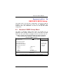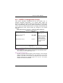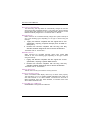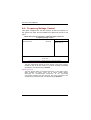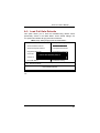
1
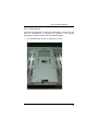
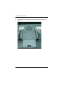
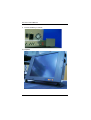
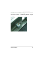
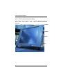
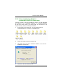
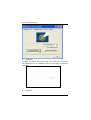
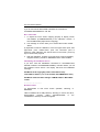
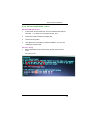
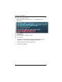
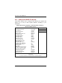
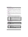
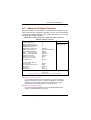
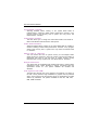
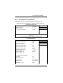
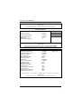
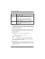
PC 6170
17” Pentium-M PANEL PC
User’s Manual
Disclaimers
The information in this manual has been carefully checked and is believed to be
accurate. Acnodes Co., Ltd. assumes no responsibility for any infringements of
patents or other rights of third parties, which may result from its use.
Acnodes assumes no responsibility for any inaccuracies that may be contained in this
document. Acnodes makes no commitment to update or to keep current the
information contained in this manual.
Acnodes reserves the right to make improvements to this document and/or
product at any time and without notice.
No part of this document may be reproduced, stored in a retrieval system, or
transmitted, in any form or by any means, electronic, mechanical, photocopying,
recording, or otherwise, without the prior written permission of Acnodes Co., Ltd.
©Copyright 2005 by Acnodes Co., Ltd.
All rights reser ved.
April 2005, Version A1
ii
Safety Approvals
‹
CE Marking
‹
FCC Class A
FCC Compliance
This equipment has been tested and complies with the limits for a
Class A digital device, pursuant to Part 15 of the FCC Rules. These
limits are designed to provide reasonable protection against harmful
interference in a residential installation. If not installed and used in
accordance with proper instructions, this equipment might generate or
radiate radio frequency energy and cause harmful interference to
radio communications. However, there is no guarantee that
interference will not occur in a particular installation. If this equipment
does cause harmful interference to radio or television reception, which
can be determined by turning the equipment off and on, the user is
encouraged to try to correct the interference by one or more of the
following measurers:
1. Reorient or relocate the receiving antenna.
2. Increase the separation between the equipment and receiver.
3. Connect the equipment into an outlet on a circuit different from
that to which the receiver is connected.
4. Consult the dealer or an experienced radio/TV technician for help.
Shielded interface cables must be used in order to comply with
emission limits.ou
iii
Safety Precautions
Before getting started, read the following important cautions.
1. The PC 6170 does not come equipped with an operating
system. An operating system must be loaded first before
installing any software into the computer.
2. Be sure to ground yourself to prevent static charge when
installing the internal components. Use a grounding wrist strap
and place all electronic components in any static-shielded
devices. Most electronic components are sensitive to static
electrical charge.
3. Disconnect the power cord from the PC 6170 before making
any installation. Be sure both the system and the external
devices are turned OFF. Sudden surge of power could
ruin sensitive components.
Make
sure
the
PC 6170 is properly grounded.
4. The brightness of the flat panel display decreases with usage.
However, hours of use vary depending on the application
environment.
5. Turn OFF the system power before cleaning. Clean the
system using a cloth only. Do not spray any liquid cleaner
directly onto the screen. The PC 6170 may come with or w/o a
touch screen. Although the touch screen is chemical resistant,
it is recommended that you spray the liquid cleaner on a cloth
first before wiping the screen. In case your system comes
without the touch screen, you must follow the same
procedure and not spray any cleaner on the flat panel directly.
6. Avoid using sharp objects to operate the touch screen.
Scratches on the touch screen may cause malfunction or
internal failure to the touch screen.
7. The flat panel display is not susceptible to shock or vibration.
When assembling the PC 6170, make sure it is securely
installed.
iv
5. Do not open the system’s back cover. If opening the cover for
maintenance is a must, only a trained technician is allowed to do
so. Integrated circuits on computer boards are sensitive to static
electricity. To avoid damaging chips from electrostatic discharge,
observe the following precautions:
9
Before handling a board or integrated circuit, touch an
unpainted portion of the system unit chassis for a few
seconds. This will help to discharge any static electricity
on your body.
9 When handling boards and components, wear a
wrist-grounding strap, available from most electronic
component stores.
Trademarks Acknow ledgments
Acnodes is a trademark of Acnodes Co., Ltd.
IBM, PC/AT, PS/2, VGA are trademarks of International
Business Machines Corporation.
Intel and Pentium are trademarks of Intel Corporation.
MS-DOS, Microsoft C and QuickBASIC are trademarks of
Microsoft Corporation.
VIA is a trademark of VIA Technologies, Inc.
SST is a trademark of Silicon Storage Technology, Inc.
UMC is a
Corporation.
trademark
of
United
Microelectronics
Other brand names and trademarks are the properties of
their respective owners.
v
This page does not contain any information.
vi
Table of Contents
Chapter 1 Introduction ------------------------------- 1
1.1
General Description ........................................... 1
1.2
Specifications .................................................... 2
1.3
Dimensions ........................................................ 5
1.4
Front View and I/O Outlets ................................ 6
1.5
1.4.1
Front Vi ew .............................................................. 6
1.4.2
I/O Outl et ............................................................... 7
Package list........................................................ 8
Chapter 2 Hardware Installatioin ----------------- 9
2.1
CPU and DRAM Installation ............................... 9
2.2
HDD Installation ............................................... 11
2.3
CD-ROM Installation ........................................ 13
2.4
Add-on Card Installation ................................. 15
2.5
3 x Serial Ports ................................................ 16
2.6
Parallel Port ..................................................... 16
2.7
VGA .................................................................. 16
2.8
Ethernet............................................................ 17
2.9
Mountings: Panel/Wall/Desktop/VESA/Rack ... 18
2.9.1
VESA -A RM ............................................................. 18
2.9.2
Wall Mount ............................................................ 19
2.9.3
Desktop Ki t Assembl y............................................ 21
2.9.4
Panel -mount Kit A ssembly .................................... 23
2.9.5
Rack mounti ng A ssembl y ..................................... 24
Chapter 3 Driver Installation --------------------- 25
3.1
System ............................................................. 25
3.2
Touch Screen ................................................... 26
3.2.1
Speci fi cation ........................................................ 26
Table of Contents
vii
3.3
3.2.2
Driver Installation- Wi ndows
98/2000/XP/CE.NET/XP-Embedded ...................... 27
3.2.3
Driver Installati on- DOS ......................................... 29
3.2.4
Driver Installati on- Li nux ........................................ 31
Dual LAN .......................................................... 33
Chapter 4 Embedded O.S. Installation -------- 35
4.1
Windows XP Embedded ................................... 35
4.1.1 Penmount Touch Screen ...................................... 35
4.2
Windows CE.NET 4.2 ....................................... 36
4.2.1
Calibrati on Touch Screen ..................................... 36
Appendix A SB83810 BIOS Setup -------------- 37
A.1
Standard CMOS Setup Menu ........................... 37
A.2
Advanced BIOS Features ................................. 40
A.3
Advanced Chipset Features ............................ 45
A.4
Integrated Peripherals ..................................... 47
A.5
Power Management Setup ............................... 52
A.6
PnP/PCI Configuration Setup .......................... 57
A.7
PC Health Status .............................................. 59
A.8
Frequency/Voltage Control.............................. 60
A.9
Load Fail-Safe Defaults ................................... 61
A.10 Load Optimized Defaults ................................. 62
Appendix B Power Supply Specification ----- 63
viii
Table of Contents
PC 6170 User’s Manual
Chapter
1
Introduction
This chapter contains the general information and the detail
specifications of the PC 6170. Chapter 1 includes the following
sections:
„
„
„
„
„
1.1
General Description
System Specification
Dimensions
Front View & I/O Outlets
Package List
General Description
The PC 6170 is an ultra slim Panel PC which equipped with superior
Pentium® M processor and 17" SXGA LCD display. PC 6170
has friendly user interface design of using front access USB, may
let the customers easily connect keyboard/mouse and USB storage
device. In addition, with P-M CPU and the advanced radiation design,
PANEL1170-810 has better stability and the ultra slim overhead
construction. The Back Door design also makes PC 6170 to be
extremely easy to maintain.
Front Access USB Ports & OSD
To enhance the system for easy maintenance and upgrade, the two
front USB ports have been build-in to the front panel. By connecting
the USB storage devices to the front USB ports, users can upgrade or
maintain the software without dismount the panel PC from the rack.
The OSD control keypads allows the users to tune the display
brightness and position at front panel which ensures the users always
get the best display condition for any specific application.
Most Reliable and Stable Design-Intel® Pentium® M
Processor
The Pentium®-M processor delivers outstanding
computing
performance and low-power enhancements. Therefore, with the
remarkable radiation design and using P-M CPU, PC 6170 is
Introduction
1
PC 6170 User’s Manual
a high stability and high reliable Panel PC. At the same time, with the
Ultra Slim case design, customers can easily install PANEL1170-810
everywhere.
Easy-to-Maintenance Design: Back Door
The back panel of the
PC 6170 was
anchored
by handremovable fasten screws. Users can install the CPU, Memory, and
HDD without using screw driver to open the main cabinet. This
modular design helps to minimize system down-time for maintenance.
The two front accessible USB ports also enable the easy connection
of input devices such as Keyboard or Mouse. By connecting to USB
FDD, CD-ROM, or Memory Stick, users can update the newest
software to the system or download the system information to memory
devices.
1.2
Specifications
Main CPU board
„
„
„
„
„
„
„
CPU: Intel® Pentium® M up 1.8GHz
System Chipset: Intel® 855GME/6300ESB
BIOS: Phoenix-Award BIOS, Y2K compliant 4Mbit Flash,
DMI, Plug and Play SmartView for multiple LCD
type selection, display mode option and
application extension features RPL/PXE Ethernet
Boot ROM
“Load Optimized Default” to backup customized
Setting in the BIOS flash chip to prevent from
CMOS battery fail
System Memory: One 184-pin DIMM socket
200/266/333MHz ECC/non-ECC DDR
SDRAM supported Maximum SDRAM of
up to 1GB
L2 Cache: Integrated in CPU
Bus Clock: 400 MHz
Watchdog Timer: Integrate Intel® 6300ESB
Up to 300 levels as Reset feature
2
Introduction
PC 6170 User’s Manual
I/O System
„
−
−
−
−
−
−
„
Standard I/O:
3 x serial ports with power; 2 x RS-232, 1 x
RS-232/422/485 jumper selectable
1 x parallel port, SPP/EPP/ECP
1 x PS/2 for Keyboard Interface
1 x PS/2 for Mouse Interface
3 x USB Ports 2.0 compliant(1 at rear; 2 at front panel)
1 x 15 pin(female) for VGA output
Ethernet:
Realtek 8100C PCI Bus 10/100M Base-T
Wake On LAN (via ATX power supply)
Equipped with RJ-45 interface
Realtek RTL8110S for 10/100/1000Base-T
„
Audio:
Realtek ALC202A AC’97 codec audio
Amplify for speaker-out with 2.5 W for each channel
MIC-in, Line-in, Line-out/Speaker-out (jumper
selectable)
„
Onboard IDE:
4 channels up to 6 devices (2 parallel ATA-100 and 2
serial ATA-150)
RATA-100 as PIO Mode 0-4, DMA Mode 0-2 and Ultra
DMA/33/66/100
„
Onboard Serial ATA:
Independent DMA operation on two ports.
Data transfer rate up to 150 Mbyte/s
Altemate Device IDE and RAID Class Code option for
support of Soft RAID.
Introduction
3
PC 6170 User’s Manual
System Specification
„
„
17” TFT LCD
Disk drive housing:
− 1x Build-in Slim type FDD,
− 1x optional slim type CD-ROM diver,
− 1 x internal 3.5” drive (or 2X 2.5” HDD)
180W AC power supply
Heat dispensing design
One slot for PCI expansion
Net weight:
− 13.5 Kgs
Dimension (main body size):
− 482.8 x 354.8 x 105.9 mm
Operating temperature:
− O° to 45°C ; Relative umidity:50%
Relative humidity:
− 10% to 85% @ 40° C, on-condensing
Altitude:
− 10,000 ft. (3,000 meters)
Vibration (operating):
− 5 to 500 Hz, 1 G random
Shock (operating):
− 10 G peak acceleration (11 msec. duration)
4
Introduction
PC 6170 User’s Manual
1.3
Dimensions
The following diagrams show the dimensions and outlines of
PC 6170.
Introduction
5
PC 6170 User’s Manual
1.4
Front View and I/O Outlets
1.4.1 Front View
The figure below
PC 6170 front panel.
6
shows
the
features and controls
on the
Introduction
PC 6170 User’s Manual
1.4.2 I/O Outlet
The following figure shows the I/O locations of the PC 6170. Most of
the I/O connectors are located on the back panel of the PC 6170.
17
16
15
12
14
9
11
13
10
8
7
5
4
6
3
2
1
1:
AC inlet
10:
VGA
2:
Power Switch
11:
USB v 2.0
3:
Line-in
12:
COM3 Port(for T/S)
4:
Mic
13:
COM1 Port
5:
Line-Out
14:
COM2 Port
6:
Mouse
15:
COM4 Port
7:
Keyboard
16:
PRN (Parallel Port)
8:
10/100 Ethernet
17:
PCMCIA Slot
9:
10/100/1000 Ethernet
Introduction
7
PC 6170 User’s Manual
1.5
Package list
When you receive the PC 6170 there are following items in the
package.
1. P1170-810 x 1
2. CPU cooler x 1
3. AC power cord x 1 (U.S standard)
4. Panel mount kit x 10
5. Desktop kit x 2
6. VESA ARM kit x 1
7. Wall mount kit x 1
8. CD driver x1
8
Introduction
PC 6170 User’s Manual
Chapter
2
Hardware Installation
The PC 6170 provides lots of flexible ways for you to select different
configuration such as CPU, CD-ROM and more. The chapter will show
you how to install the hardware. It includes:
2.1
CPU and DRAM Installation
The standard PC 6170 system was designed Pentium M level CPUs.
The build-in CPU board provides one 184-pin DDR DIMM socket
that supports system memory up to 1GB. And, there is one miniPCI type-III Socket.
When upgrading the CPU, DRAM, or Mini-PCI, refer to the following
instructions and illustration:
1.
Unscrew five screws in the back door.
Hardware Installation
9
PC 6170 User’s Manual
2.
Install the CPU, DDR DRAM and Mini-PCI card in the
P-1170-810.
DRAM
CPU
Mini-PCI
10
Hardware Installation
PC 6170 User’s Manual
2.2
HDD Installation
The PC 6170 offers a convenient drive bay module for users to install
HDD. The PC 6170 offers one 3.5” HDD drive for users to install.
If you want to install two 2.5” HDDs, the PC 6170 also
provides the 3.5” to 2.5” drive holder to meet your requirement.
Please follow the steps:
1. Open the back door.
2. Unscrew 3 screws and remove the riser card bracket kit.
Hardware Installation
11
C 6170 User’s Manual
3. Unscrew 1 screw from the HDD drive bracket, and push the HDD
bracket kit.
(1) Unscrew the
screw
(2) Push the HDD
bracket kit
4. Set the 3.5” HDD (or 2.5” HDD) in the HDD bracket kit and fix it by
4 screws around the bracket kit.
5. Installation complete.
12
Hardware Installation
PC 6170 User’s Manual
2.3
CD-ROM Installation
The PC 6170 offers a convenient drive bay module for users to install
CD-ROM. When installing the CD-ROM, refer to the following
instructions and illustration:
1. Open the back door.
2. Unscrew 3 screws and remove the Riser card bracket kit.
3. Secure 2 screws to fix the CD-ROM PCB board.
Hardware Installation
13
PC 6170 User’s Manual
4. Put the CD-ROM in the drive bracket and fix it by 6 screws.
14
Hardware Installation
PC 6170 User’s Manual
5. Fix CD-ROM drive bracket by two screws at the side of the
PC 6170.
2.4
Add-on Card Installation
The PC 6170 provides a riser card for PCI slots expansion. The riser
card assembly can accommodate both half-size expansion cards. To
install the riser card, refer to the following figure and instructions
below:
When upgrading the add-on card, refer to the following instructions
and illustration:
1. Open the back door of the system.
2. Unscrew 2 screws.
3. Plug the add-on card into the slot.
Hardware Installation
15
PC 6170 User’s Manual
2.5
3 x Serial Ports
The PC 6170 provides three onboard serial ports installed on the back
bottom side of the chassis. For systems, COM1 and COM2 are RS232 and COM4 is RS-232/422/485. Each serial port is with
+5V/+12V power capabilities on both Pin 1 and Pin 8, ready to
accommodate a wide array of serial devices, such as fax modem,
scanner, serial mouse and touch screen...etc.
COM1 to COM4 are all D-SUB 9-pin connectors. To connect any
serial devices, just plug in the device connector to the 9-pin D-SUB. In
terms of transmission distance, the RS-422/485 will perform better
than RS-232. In this case, COM4 is suggested to be set to
RS-422/485 and the related jumpers have to be set correctly first (see
the system board User’s Manual). The RS-422/485 pin assignment is
listed as follows;
Sig n a l Na me
Pi n #
1
2
6
3
7
4
8
5
9
1
2
3
4
5
6
7
8
9
10
2.6
R2 -422
TX-
RS -485
D A TA -
N o co nn ec t o r
No c o nn ect o r
TX+
D A TA+
N o co nn ec t o r
No c o nn ect o r
RX +
No c o nn ect o r
N o co nn ec t o r
No c o nn ect o r
RX -
No c o nn ect o r
N o co nn ec t o r
No c o nn ect o r
GN D
N o co nn ec t o r
GN D
No c o nn ect o r
Parallel Port
The printer interface is a 25-pin D-SUB connector. To connect any
parallel device, just plug in the device connector to the 25-pin D-SUB.
2.7
VGA
The PC 6170 has an analog RGB interface connector. It is able to
connect to an expansion CRT monitor, and the system can display
on both the flat panel and the CRT simultaneously.
16
Hardware Installation
PC 6170 User’s Manual
2.8
Ethernet
The PC 6170 provides an NE2000 compatible Ethernet
(RJ-45) interface. For network connection, just plug in one cable end
of the PC 6170 10/100/1000-Base-T Hub into the standard RJ-45
connector. The pin assignment of the RJ-45 is listed below;
R J - 4 5 C o n n e c to r Pin A ssignme nt
Pi n
Signa l
1
TX+ (Data tr an smission positive
2
TX- (Data transmission negative)
3
Rx +(Da ta reception positive)
4
RJ 45 te rm ination
5
RJ 45 te rm ination
6
Rx - (Data reception negative)
7
RJ 45 te rm ination
8
RJ 45 te rm ination
Hardware Installation
1 2 3 4 5 6 7 8
RJ-45
17
PC 6170 User’s Manual
2.9
Mountings:
Panel/Wall/Desktop/VESA/Rack
There are 5 application options for
Panel/Wall/Desktop/VESA/Rack mountings.
the
PC 6170,
2.9.1 VESA-ARM
The PC 6170 provides two ways for VESA mount: 75x75 mm and
100x100 mm. Screw four screws to fix the kit (included in the
package) in the back chassis.
18
Hardware Installation
PC 6170 User’s Manual
2.9.2 Wall Mount
The PC 6170 is designed for Wall mount application. To mount the PC
6170, the standard set of mounting kit (included in the system
packaging) is needed. Please refer to the following figure.
1. Fix VESA bracket kit in back of chassis by 4 screws.
Hardware Installation
19
PC 6170 User’s Manual
2. Fix the Wall mount bracket kit in back of the VESA bracket kit by 4
screws.
20
Hardware Installation
PC 6170 User’s Manual
2.9.3 Desktop Kit Assembly
The PC 6170 is designed for desktop application. The standard
set of desktop kit is included in the system packaging. Please
refer to the following figure.
1. Fix VESA bracket kit in back of chassis by 4 screws.
2. Fix the Wall mount bracket kit in back of the VESA bracket kit.
Hardware Installation
21
PC 6170 User’s Manual
3. Fix two holders by 2 screws.
4. Complete.
22
Hardware Installation
PC 6170 User’s Manual
2.9.4 Panel-mount Kit Assembly
The PC 6170 is designed for panel mount application. To mount
the PC 6170, the standard set of mounting kit (included in the system
packaging) is needed.
Hardware Installation
23
PC 6170 User’s Manual
2.9.5 Rack mounting Assembly
The PC 6170 is designed for rack mounting application. Remove
plugs from front panel. Then, user could mount PC 6170 at
their rack.
remove
remove
remove
remove
24
Hardware Installation
PC 6170 User’s Manual
Chapter
3
Driver Installation
3.1
System
PC 6170 could support with Windows 95, Windows 98 or Windows
2000/XP. To facilitate installation system driver, you should read the
instructions in this chapter carefully before you attempt
installation.
1.
Insert Driver CD and select the \P1170-810\Driver\..
2.
Select all files and follow the install procedure and press OK.
Driver Installation
25
PC 6170 User’s Manual
3.2
Touch Screen
3.2.1 Specification
To u c h S c r e e n :
For 8-wire analog resistive type
T o uc h S c r e en C o nt r o l l er :
DMC9000
Co mm u n i c a t io ns :
RS-232
Ba ud R a te :
19200 baud rate fixed
Re s o lu tion:
1024 x 1024 (10-bit A/D converter inside)
Po w e r I n p u t :
5V to 12V DC
Po w e r Co n s um pt i o n :
12V: 27mA+ i where (i = v/touch screen sheet R)
5V: 23mA+ i where (i = v/touch screen sheet R)
Bo ard Si ze :
6.0 x 2.0 cm
Po r t ra i t :
Support 90o to 270o screen rotation
S t at ic Pr o t ect i on :
ESD device option
Ot he rs :
Touch activate indication LED on board
26
Driver Installation
PC 6170 User’s Manual
3.2.2 Driver Installation- Windows
98/2000/XP/CE.NET/XP-Embedded
The touch screen of PC 6170 provides a driver for use with Windows
95, Windows 98 or Windows 2000/XP. To facilitate installation
of the touch screen driver, you should read the instructions in this
chapter carefully before you attempt installation.
1.
Insert Driver CD and select the “\P1170-810\Driver\Touch
screen\Windows 9x or 2k or XP or CE\Setup.exe”
2.
Follow the install procedure and press OK.
3.
Click Start menu and select “PenMount Utilities”. You can see
PenMount Control Panel
4.
Select the “Standard Calibrate” tab
Driver Installation
27
PC 6170 User’s Manual
5.
Calibration:
To adjust the display with touch panel, click “Calibration” and follow
the calibrate point to do calibration; there are five points on screen for
calibration.
6.
28
Press OK.
Driver Installation
PC 6170 User’s Manual
3.2.3 Driver Installation- DOS
Using “INSTALL.EXE”
software driver.
utility
to
install
PenMount
1.
Insert Driver CD and select the \P1170-810\Driver\Touch
screen\DOS\ Install.exe
2.
Press ENTER key to install the drivers to drive C or use keyboard
to key-in the hard disc drive that you plan to install the driver.
3.
The driver will ask “Do you want to modify your Autoexec.bat to
initialize PenMount? (Y/N)” Suggest you choose “YES” for
generating the initialization instructions in AUTOEXEC.BAT files.
Then follow up the instructions to complete the installation.
Identify the communication port and IRQ number
1. For the first time installation, or changing PenMount Touch
COM
port,
use
PMDETECT
(e.g.
Screen’s
C:\PENMOUNT\PMDETECT) to check the COM port and IRQ
number. PMDETECT will save the correct data to PMOUSE.CFG
file for further use.
The driver detects your communication COM port and IRQ number
from COM1 IRQ4, COM2 IRQ3, COM3…. to COM4 IRQ15.
PenMount driver can find the COM port and IRQ number
automatically. The screen will then show:
PenMount is initialized successfully!!!
Create file “pmouse.cfg”. Success.
PenMount internal settings:
Comm. Port: COM<n> IRQ<n>
..........
1. PMDETECT program is able to skip the IRQ number detecting if
you Touchscreen Driver Installation 13 do not need to detect the
specified IRQ number. For example, you do not need to detect
IRQ5, and the command is:
C:\PENMOUNT\PMDETECT -N5
Driver Installation
29
PC 6170 User’s Manual
If you do not need to detect IRQ5 and IRQ9, the command is:
C:\PENMOUNT\PMDETECT -N5 -N9
Do Calibration
1. To adjust the touch screen mapping properly to display screen,
use PM.BAT (C:\PENMOUNT\PM) to do calibration. Choose “1”
DO CALIBRATION (adjust screen mapping).
2. The message on screen asks you to select video mode number.
Select
by keyboard to start the calibration, touch the upper-center point, then
right-center point, bottom-center point and left-center point in
sequence. After calibration, the data is shown in the screen, press any
key to continue the progress.
3. After the calibration, suggest you to test touch screen and display
mapped results by choose “3” DRAWING TEST under PM.BAT
Initializing the PenMount driver
If you don’t have the initialization commands in AUTOEXEC.BAT,
initialize PenMount C:\PENMOUNT\PMINIT) controller before you use
the PenMount Touch Screen. The display will show the initialization
message:
PenMount V7.06 Copyright(c) SALT International Corp.
Test:COM<n> IRQ<n> (<n> is the number after PMDETECT done)
PenMount communication settings: COM<N> IRQ<n> Baud Rate:
<xxxx>
... ... ... ... ... ... ... ... ... ...
Demonstration
To demonstrate or test touch screen operation, selecting “3”
DRAWING
TEST in PM.BAT file of Utility Directory. Drawing on screen.The other
demonstration
program
called
“ICECREAM.EXE”
in
the
“PENMOUNT” directory can also be applied.
30
Driver Installation
PC 6170 User’s Manual
3.2.4 Driver Installation- Linux
Install PenMount driver
1.
Insert Driver CD and select the “\P1170-810\Driver\Touch\Linux
XFree86 4.x.x Driver V2.1\Driver\penmount_drv.o”
2.
Follow the install procedure and press OK.
3.
Please reboot system.
4.
Click Start menu and select “PenMount Utilities”. You can see
PenMount Control Panel
Advance Setup
1.
Before install the Touch Screen Driver, please open the file in
Linux
File /etc/rc.local
Driver Installation
31
PC 6170 User’s Manual
2.
Key-in the following words.
Setserial /dev/ttyS2 port 0x3e8 irq 10
screen port)
(set COM3 as touch
3. Save and exit.
4. Please reboot.
5. After reset system, Insert Driver CD.
Do Calibration
1.
Insert Driver CD and select the “\P1170-810\Driver\Touch\Linux
XFree86 4.x.x Driver V2.1\Calibration\ pencal-2.00”
2.
Follow the install procedure and press OK.
3.
Please reboot system.
32
Driver Installation
PC 6170 User’s Manual
3.3
Dual LAN
The Dual LAN of PC 6170 provides a driver for use with
Windows 95, Windows 98 or Windows 2000/XP. To facilitate
installation of the Dual LAN driver, you should read the instructions in
this chapter carefully before you attempt installation.
1.
Insert Driver CD and select the “\P1170-810\Driver\ Dual
LAN\Win9x_2000_XP(V1.30.611)\Setup.exe”
2.
Follow the install procedure and press OK.
Driver Installation
33
PC 6170 User’s Manual
This page does not contain any information.
34
Driver Installation
PC 6170 User’s Manual
Chapter
4
Embedded O.S. Installation
4.1
Windows XP Embedded
Supported devices are as follows:
Onboard Multi I/O
„
Floppy drive
„
Parallel port
„ 16C550 UARTs compatible serial port
„
IrDA for wireless communication
Onboard IDE
„
IDE HDD
„
IDE
CDROM USB
PS2 Keyboard and mouse
CRT/LCD display
Dual LAN
Giga LAN
Compact flash
Onboard audio
Touch screen
4.1.1
Penmount Touch Screen
PC 6170 has Penmount touch screen on COM3, which is disabled by
default.
Before you can use and calibrate it, you should :
1. Set up Penmount touch device driver by executing
c:\Program Files\PenMount\setup.exe. When installation is
finished, an icon “PM” appears on the Taskbar.
2. Calibrate Penmount touch by clicking on “PM” icon and doing
calibration
Embedded O.S. Installation
35
PC 6170 User’s Manual
3. Restart computer.
4.2
Windows CE.NET 4.2
Supported devices are as follows:
Onboard Multi I/O
„ Floppy drive
„ Parallel port
„ 16C550 UARTs compatible serial port
„ IrDA for wireless communication
Onboard IDE
„ IDE HDD
„ IDE CDROM
USB
PS2 Keyboard and mouse
CRT/LCD display Compact
flash
Onboard audio
Touch screen
Note: PC 6170 does not support Ethernet.
4.2.1 Calibration Touch Screen
In this image we add PenMount Touch drivers and utilities.
customized for 1280x1024.
It is
Calibration:
Click “Start\Programs\PenMount
TouchPanel\Calibration” menu item
36
Embedded O.S. Installation
PC 6170 User’s Manual
Appendix
A
SBC83810 BIOS Setup
The board used in the PC 6170 is SBC83810. The different settings
available in the Award BIOS that comes with the SBC83810. Also
contained here are instructions on how to set up the BIOS
configuration.
A.1 Standard CMOS Setup Menu
The items in Standard CMOS Setup Menu are divided into 10
categories. Each category includes no, one or more than one setup
items. Use the arrow keys to highlight the item and then use the
<PgUp> or <PgDn> keys to select the value you want in each item.
CMOS Setup Utility-Copyright © 2000-2004 Aw ard Softw are
Stand ard CMOS Features
Date (mm:dd :yy )
Time (hh:mm:ss)
f
f
f
f
IDE
IDE
IDE
IDE
Thu, Jan 10 2002
2 : 31 :
Primary Master
Primary Sl a v e
Secondary Master
Secondary Sl ave
Drive A
Drive B
1.44M, 3.5 in.
None
Video
Ha lt On
EGA/VGA
All, Bu t Keyboard
ÇÈ ÆÅ : Mo ve
Item He lp
24
Menu Level f
Ch ange the
Da y, month,
Year and
Ce ntu r y
E n te r: S e le ct
+/- / P U /P D : Va lu e
F 1 0 : S a ve E S C : E xi t F 1 :
Gene ral He lp
F 5 : P r evious Values F6: Fail- Saf e D e f a ults F7: O p timize d D e f a ults
SBC83810 BIOS Setup
37
PC 6170 User’s Manual
Date
The date format is <day>, <date> <month> <year>. Press <F3> to show
the calendar.
day
The day of we e k , from Sun to S a t, determined by the B IOS, is
read only
date
The date, fr om 1 to 31 (o r the maximu m allowed in the
month) , can key in the nu merical / functi on key
month
The month, Jan th rough De c.
year
The year, depends on the year of BIOS
Time
The time format is <hour> <minute> <second> accepting either functions
key or numerical key. The time is calculated based on the 24-hour
military-time clock. For example, 1 p.m. is 13:00:00.
Primary Master/Primary Slave/Secondary Master/Secondary
Slave
The categories identify the types of one channel that have been installed in
the computer. There are 45 predefined types and 2 users definable
types are for Enhanced IDE BIOS. Type 1 to Type 45 is predefined. Type
User is user-definable.
Press <PgUp>/<+> or <PgDn>/<−> to select a numbered hard disk type
or type the number and press <Enter>. Note that the specifications of
your drive must match with the drive table. The hard disk will not work
properly if you enter improper information within this category. If your
hard disk drive type does not match or is not listed, you can use Type
User to define your own drive type manually.
If you select Type User, related information is asked to be entered to the
following items. Enter the information directly from the keyboard and
press <Enter>. This information should be provided in the documentation
from your hard disk vendor or the system manufacturer.
If the controller of HDD interface is ESDI, select “Type 1”. If
the controller of HDD interface is SCSI, select “None”.
If the controller of HDD interface is CD-ROM, select “None”.
CYLS.
HEADS
PRECOMP
number of cylinders LANDZONE
number of heads
SECTORS
write precom
MODE
landing zone
number of sectors
HDD access m ode
If there is no hard disk drive installed, select NONE and press <Enter>.
38
SBC83810 BIOS Setup
PC 6170 User’s Manual
Drive A type/Drive B type
The category identifies the types of floppy disk drive A or drive B installed
in the computer.
None
360K, 5.25 in
1.2M, 5.25 in
720K, 3.5 in
1.44M, 3.5 in
2.88M, 3.5 in
No floppy drive installed
5.25 inch P C-type standard drive; 360K b
capacity
5.25 inch A T-type high-density dri ve; 1.2M B
capacity
3.5 inch double-sided drive; 720K b capacity
3.5 inch double-sided drive; 1.44MB capacity
3.5 inch double-sided drive; 2.88MB capacity
Halt On
This field determines whether the system will halt if an error is detected
during power up.
No errors
The system boot will halt on any error
detected. (default)
All errors
Whenever the BIOS detect a non-fatal error, the
system will stop and you will be prompted.
The system boot will not stop for a keyboard
error; it will stop for all other errors.
All, But
Keyboard
All, But Diskette
All, But Disk/Key
SBC83810 BIOS Setup
The system boot will not stop for a disk error;
it will stop for all other errors.
The system boot will not stop for a keyboard or
disk error; it will stop for all other errors.
39
PC 6170 User’s Manual
A.2 Advanced BIOS Features
This section allows you to configure and improve your system and
allows you to set up some system features according to your
preference.
CMOS Setup Utility-Copyright © 2000-2004 Aw ard Softw are
Ad vanced BIOS Featur es
CPU Featur e
Press Ente r
Hard Di sk Boot Priority
Press Ente r
Viru s Warn ing
CPU L1 & L2 Ca che
CPU L2 Ca che
Quick Powe r On Self Test
Fi rst Bo o t De vi ce
Second Boot Device
Third Boot Devi c e
Boot Other De vice
S wap Fl oppy Dr ive
Boot Up Floppy Seek
Boot Up NumLock Status
Ga te A2 0 Op tio n
Typematic Ra te Setting
Typematic Ra te (Chars/Sec)
Typematic De lay (Msec)
Securi ty Opti on
APIC Mode
PS/2 Mouse Functi on Co ntrol
OS Se lect for DR AM >64MB
Report No FDD Fo r WIN 95
Full Sc reen Logo Show
Small Screen Show
Summary Screen Show
Di splay board ID
Di sabled
Enab led
Enab led
Enab led
HD D-0
Floppy
S CSI
Enab led
Di sabled
Enab led
On
Fa st
Di sabled
6
250
Setup
Enab led
Enab led
Non-OS2
No
Di sabled
Disabled
Enab led
Di sabled
ÇÈ ÆÅ : Mo ve
Item He lp
Menu Level f
+/- / P U /P D : Va lu e
F 1 0 : S a ve E S C : E xi t F 1 :
Gene ral He lp
F 5 : P r evious Values F6: Fail- Saf e D e f a ults F7: O p timize d D e f a ults
40
E n te r: S e le ct
SBC83810 BIOS Setup
PC 6170 User’s Manual
Hard Disk Boot Priority
This item can select boot device priority.
Virus Warning
This option flashes on the screen. During and after the system boot up,
any attempt to write to the boot sector or partition table of the hard disk
drive will halt the system with the following message. You can run an
anti-virus program to locate the problem. The default setting is
“Disabled”.
! WARNING !
Disk boot sector is to be modified
Type “Y” to accept write or “N” to abort write
Award Software, Inc.
Enabled
Disabled
NOTE:
Activates automatically when the system boots up
causing a warning message to appear when there is an
attempt to access the boot sector or hard disk partition
table.
No warning message will appear when attempts to
access the boot sector or hard disk partition table are
made.
This function is only available with DOS and other
operating systems that do not trap INT13.
CPU L1 & L2 Cache
These two options speed up memory access. However, it depends on the
CPU/chipset design. The default setting is “Enabled”. CPUs with no
built-in internal cache will not provide the “CPU Internal Cache” item on
the menu.
Enabled
Disabled
Enable cache
Disable cache
Quick Power On Self Test
This option speeds up Power on Self Test (POST) after you turn on the
system power. If set as Enabled, BIOS will shorten or skip some check
items during POST. The default setting is “Enabled”.
Enabled
Disabled
SBC83810 BIOS Setup
Enable Quick POST
Norm al POST
41
PC 6170 User’s Manual
First/Second/Third Boot Device
These items allow the selection of the 1st, 2nd, and 3rd devices that the
system will search for during its boot-up sequence. The wide range of
selection includes Floppy, LS120, ZIP100, HDD0~3, SCSI, and CDROM.
Boot Other Device
This item allows the user to enable/disable the boot device not listed on
the First/Second/Third boot devices option above. The default setting is
Enabled.
Swap Floppy Drive
This allows you to determine whether to enable Swap Floppy Drive or not.
When enabled, the BIOS swap floppy drive assignments so that Drive A
becomes Drive B, and Drive B become Drive A. By default, this field is
set to Disabled.
Boot Up Floppy Seek
During POST, BIOS will determine the floppy disk drive type, 40 or 80
tracks, installed in the system. 360Kb type is 40 tracks while 720Kb,
1.2MB and 1.44MB are all 80 tracks. The default value is “Enabled”.
BIOS searches for floppy disk drive to determine if it is
40 or 80 tracks. Note that BIOS can not tell from
720K, 1.2M or 1.44M drives type as they are all 80
tracks.
BIOS will not search for the type of floppy disk dri ve
by track number. There will be no warning message
displayed if the drive installed is 360K.
Enabled
Disabled
Boot Up NumLock Status
This option enables and disables the number lock function of the keypad.
The default value is “On”.
On
Keypad functions confine with numbers
Off
Keypad functions convert to special functions (i.e.,
left/right arrow keys)
Gate A20 Option
The default value is “Fast”.
42
Normal
The A 20 signal is controlled by keyboard controller or
chipset hardware.
Fast
Default: Fast. The A20 signal is controlled by P ort
92 or chipset specifi c method.
SBC83810 BIOS Setup
PC 6170 User’s Manual
Typematic Rate Setting
This determines the typematic rate of the keyboard. The default value is
“Disabled”.
Enabled
Disabled
Enable typematic rate and typemati c delay
programming
Disable typem atic rate and typem atic delay
programming. The system BIOS will use default
value of these 2 items and the default is controlled
by keyboard.
Typematic Rate (Chars/Sec)
This option refers to the number of characters the keyboard can type per
second. The default value is “6”.
6
8
10
12
15
20
24
30
6 characters per second
8 characters per second
10 characters per second
12 characters per second
15 characters per second
20 characters per second
24 characters per second
30 characters per second
Typematic Delay (Msec)
This option sets the display time interval from the first to the second
character when holding a key. The default value is “250”.
SBC83810 BIOS Setup
250
250 msec
500
500 msec
750
750 msec
1000
1000 msec
43
PC 6170 User’s Manual
Security Option
This item allows you to limit access to the system and Setup, or just to
Setup. The default value is “Setup”.
System
The system will not boot and access to Setup will be
denied if the incorrect password is entered at the
prompt.
Setup
The system will boot, but access to Setup will be denied if
the correct password i s not entered at the prompt.
NOTE:
To disable security, select PASSWORD SETTING at
Main Menu and then you will be asked to enter
password. Do not type anything, just press <Enter>
and it will disable security. Once the security is
disabled, the system will boot and you can enter
Setup freely.
OS Select for DRAM >64MB
This segment is specifically created for OS/2 when DRAM is larger than
64MB. If your operating system is OS/2 and DRAM used is larger the
64MB, you have to select “OS 2”, otherwise (under non-OS2), default is
NON-OS2. The default value is “Non-OS2”.
Report No FDD For Win 95
This option allows Windows 95 to share IRQ6 (assigned to a floppy disk
drive) with other peripherals in case the drive does not exist. The default
setting is “No”.
44
SBC83810 BIOS Setup
PC 6170 User’s Manual
A.3 Advanced Chipset Features
Since the features in this section are related to the chipset on the
CPU board and are completely optimized, you are not recommended
to change the default settings in this setup table unless you are well
oriented with the chipset features.
CMOS Setup Utility-Copyright © 1984-2001 Aw ard Softw are
Ad vanced Chipset Featu res
DRAM Timing
CA Ss Latency Ti me
Acti ve to Re charge De lay
D RAM RA S # to CA S# De l a y
DRAM RAS# Re charge
D RAM Data In te g r ity Mo de
MGM Co re Fr eq uency
System B IOS C acheable
Video
BIOS Ca cheable
Memory Ho le At 15 M-16M
Delayed Transacti on
Delay Prior to Thermal
AGP Aperture S i ze (M B)
In it Di splay Fi rst
By SPD
2.5
7
3
3
No n -E CC
Au to Max 400/333MHz
Enable
Di sabled
Di sabled
Di sabled
16 Min
64
Onboard
** On-Chip VGA Se tting **
On-Chip VG A
On-Chip Frame Bu ffe r Size
Boot Displ ay
l Scaling
Panel Number
Enabled
32 MB
Au to Pane
Au to
640 x480
ÇÈ ÆÅ : Mo ve
Ite m He lp
Menu Level f
E n te r: S e le ct
+/- / P U /P D : Va lu e
F 1 0 : S a ve E S C : E xi t F 1 :
Gene ral He lp
F 5 : P r evious Values F6: Fail- Saf e D e f a ults F7: O p timize d D e f a ults
SDRAM CAS latency Time
You can select CAS latency time in HCLKs 2, 3, or Auto. The board
designer should set the values in this field, depending on the DRAM
installed. Do not change the values in this field unless you change
specifications of the installed DRAM or the installed CPU.
DRAM Data Integrity Mode
This option sets the data integrity mode of the DRAM installed in the
system. The default setting is “Non-ECC”.
SBC83810 BIOS Setup
45
PC 6170 User’s Manual
System BIOS Cacheable
Selecting Enabled allows caching of the system BIOS ROM at
F0000h-FFFFFh, resulting in better system performance. However, if any
program writes to this memory area, a system error may result. The
default value is “Disabled”.
Video BIOS Cacheable
This item allows you to change the Video BIOS location from ROM to
RAM. Video Shadow will increase the video speed.
Video RAM Cacheable
Selecting Enabled allows caching of the video BIOS ROM at C0000h to
C7FFFh, resulting in better video performance. However, if any program
writes to this memory area, a system error may result. The default value
is “Disabled”.
Memory Hole at 15M-16M
You can reserve this area of system memory for ISA adapter ROM.
When this area is reserved, it cannot be cached. The user information of
peripherals that need to use this area of system memory usually
discusses their memory requirements. The default value is “Disabled”.
Delayed Transaction
The chipset has an embedded 32-bit posted write buffer to support delay
transactions cycles. Select Enabled to support compliance with PCI
specification version 2.1. The options available are Enabled and
Disabled.
AGP Aperture Size (MB)
The field sets aperture size of the graphics. The aperture is a portion of
the PCI memory address range dedicated for graphics memory address
space. Host cycles that hit the aperture range are forwarded to the AGP
without any translation. The options available are 4M, 8M, 16M, 32M,
64M, 128M and 256M.
46
SBC83810 BIOS Setup
PC 6170 User’s Manual
A.4 Integrated Peripherals
This option sets your hard disk configuration, mode and port.
CMOS Setup Utility-Copyright © 1984-2001 Aw ard Softw are
Integrated Peripherals
►On Ch ip I DE Dev i ce
Press Enter
►On Board De vice
Press Enter
►Superior De vice
Onboard LAN boot ROM
Press Enter
Di sabl e
ÇÈ ÆÅ : Mo ve
Menu Level f
E n te r: S e le ct
+/- / P U /P D : Va lu e
F 1 0 : S a ve E S C : E xi t F 1 :
Gene ral He lp
F 5 : P r evious Values F6: Fail- Saf e D e f a ults F7: O p timize d D e f a ults
CMOS Setup Utility-Copyright © 1984-2001 Aw ard Softw are
On Chip IDE Device
IDE DM A transfer Access
Enabled
On-Chip Pr imary P CI IDE
Enabled
IDE Pr imary Master P IO
Auto
IDE Pr imary Master P IO
Auto
IDE Pr imary Master UDMA
IDE Pr imary Master UDMA
On-Chip Pr imary P CI IDE
IDE Se condary Master PIO
Se condary Master PIO
Se condary Master PIO
Se condary Master PIO
Auto
Auto
Enabled
Auto IDE
Auto IDE
Auto IDE
Auto
** On-Chip Se ri al ATA Setting **
SATA Mode
On-Chip Se rial ATA
IDE
Auto
Seri al ATA Po r t0
Seri al ATA Po r t1
Primary Master
Primary Master
IDE HDD Bl ock Mode
Enabled
SBC83810 BIOS Setup
Menu Level f
47
PC 6170 User’s Manual
ÇÈ ÆÅ : Mo ve
E n te r: S e le ct
+/- / P U /P D : Va lu e
F 1 0 : S a ve E S C : E xi t F 1 :
Gene ral He lp
F 5 : P r evious Values F6: Fail- Saf e D e f a ults F7: O p timize d D e f a ults
CMOS Setup Utility-Copyright © 1984-2001 Aw ard Softw are
On board Device
USB Co n troller
Enable
USB 2 .0 Contro l l er
Enabled
USB Keyboard Support
USB Mouse Su p port
A C97 Audio
Hance Rapid Watc hdog
Di sa bl ed
Di sabl ed
Auto
0
ÇÈ ÆÅ : Mo ve
Menu Level f
E n te r: S e le ct
+/- / P U /P D : Va lu e
F 1 0 : S a ve E S C : E xi t F 1 :
Gene ral He lp
F 5 : P r evious Values F6: Fail- Saf e D e f a ults F7: O p timize d D e f a ults BIOS
Set u p Ut ili ty- Cop yri gh t © 1984 -2 001 Aw a rd S of tw are Supe r I
O De vi ce
Onboard FDC Controller
Onboard Serial Port 1
Onboard Serial Port 1
UART Mode Select
Red , Tx D Ac ti ve
IR Tran smission Delay
UR2 Duplex Mode
Us e IR Pins
Onboard Para llel Port
Para llel Po rt Mode
EPP Mode Select
E CP Mode Us e DM A
ICH Se rial Port 1
ICH Se rial Port 1 Us e IRQ
ICH Se rial Port 2
ICH Se rial Port 2 Us e IRQ
PWRO N a fter p o we r fa il
ÇÈ ÆÅ : Mo ve
Enabled
3F8/IRQ4
2F8/IRQ3
No rm al
Hi ,L o
Enabled
Ha lf
IR-Rx2Tx2
378/IRQ7
SPP
EEP1.7
3
3E8
IRQ10
2E8
IRQ11
OFF
Menu Level f
+/- / P U /P D : Va lu e
F 1 0 : S a ve E S C : E xi t F 1 :
Gene ral He lp
F 5 : P r evious Values F6: Fail- Saf e D e f a ults F7: O p timize d D e f a ults
48
E n te r: S e le ct
SBC83810 BIOS Setup
PC 6170 User’s Manual
IDE Primary /Secondary Master/Slave PIO
The four IDE PIO (Programmed Input/Output) fields let you set a PIO
mode (0-4) for each of the four IDE devices that the onboard IDE
interface supports. Modes 0 through 4 provide successively increased
performance. In Auto mode, the system automatically determines the
best mode for each device. The options available are Auto, Mode 0,
Mode 1, Mode 2, Mode 3, and Mode 4.
IDE Primary /Secondary Master/Slave UDMA
Ultra DMA 66/100 implementation is possible only if your IDE hard drive
supports it and the operating environment includes a DMA driver
(Windows 95 OSR2 or a third-party IDE bus master driver). If your hard
drive and your system software support Ultra DMA 33/66/100, select
Auto to enable BIOS support. The options available are Auto, Mode 0,
Mode 1, and Mode 2.
On-Chip Primary/Secondary PCI IDE
The integrated peripheral controller contains an IDE interface with
support for two IDE channels. Select Enabled to activate each channel
separately. The default value is “Enabled”.
NOTE:
Choosing Disabled for these options will automatically
remove the IDE Primary Master/Slave PIO and/or IDE
Secondary Master/Slave PIO items on the menu.
USB Keyboard Support
Select Enabled if your system contains a Universal Serial Bus (USB)
controller and you have a USB keyboard.
Init Display First
This item allows you to decide to active whether PCI Slot or AGP first.
The options available are PCI Slot, AGP.
IDE HDD Block Mode
This field allows your hard disk controller to use the fast block mode to
transfer data to and from your hard disk drive.
POWER ON Function
This option allows users to select the type of power ON sequence for the
system to follow. The default value is “Button-Only”.
SBC83810 BIOS Setup
49
PC 6170 User’s Manual
BUTTON-ONLY
Password
Hot KEY
Follows the conventional way of turning OFF system
power (via power button).
Upon selecting this option, the K B POWER ON
Password line appears. Press <E nter> and you’ll be
prompted to enter and confi rm a password of your
choi ce.
After setting the password, succeeding attempts to
power ON the system will result to null. For system to
acti vate, user must input the password via keyboard
then press <Enter>.
This option i s very similar with that of P assword.
Hot-key combi nations range from Ctrl -F1 to Ctrl -F12.
User m ay define this combination from the Hot key
Power ON opti on.
Onboard FDC Controller
Select Enabled if your system has a floppy disk controller (FDC) installed
on the system board and you wish to use it. If you install and-in FDC or
the system has no floppy drive, select Disabled in this field. The options
available are Enabled, Disabled.
Onboard Serial Port 1/Port 2
Select an address and corresponding interrupt for the first and second
serial ports. The options available are 3F8/IRQ4, 2E8/IRQ3, 3E8/IRQ4,
2F8/IRQ3, Disabled, Auto.
UART2 Duplex Mode
The second serial port offers these infrared interface modes:
9
IrDA
9
ASKIR
9
Normal (default value)
NOTE:
IrDA-compliant serial infrared port
The UART Mode Select will not appear on the menu
once you disable the setting of Onboard Serial Port 2.
When UART Mode Select is set as ASKIR or IrDA, the options RxD, TxD
Active and IR Transmittion delay will appear.
Parallel Port Mode
Select an operating mode for the onboard parallel (printer) port. Select
Normal unless your hardware and software require one of the other
modes offered in this field. The options available are EPP1.9, ECP, SPP,
ECPEPP1.7, and EPP1.7.
50
SBC83810 BIOS Setup
PC 6170 User’s Manual
ECP Mode Use DMA
Select a DMA channel for the parallel port for use during ECP mode.
SBC83810 BIOS Setup
51
PC 6170 User’s Manual
A.5 Power Management Setup
The Power Management Setup allows you to save energy of your
system effectively. It will shut down the hard disk and turn OFF video
display after a period of inactivity.
CMOS Setup Utility-Copyright © 1984-2001 Aw ard Softw are
Pow er Management Setup
A CPI functi on
Enabled
A CPI Suspend Type
Powe r Management
PM Control by APM
Vid e o Off Me tho d
Video off Afte r
MODEM Us e IRQ
Suspend Mode
DD Po we r Do wn
Soft-Off by PWR-BTTN
CPU THRM -Throttling
Wake-up by PCI card
Powe rOn by Ri ng
Wake UP On LAN
USB KB Wake-Up From S3
Resume by Al arm
Date (of Month) Alarm
Time (hh:mm:ss) Alarm
S 1 (P OS )
Min Sa ving
Yes
V/ H SY NC+Bla n k
Standby
3
1 Hour H
1 5 Mi n
Instant-Off
50.0 %
Enabled
Enabled
Enabled
Disabl ed
Di sabl ed
0
0:0:0
** Re load Global Timer Events **
Primary IDE 0
Primary IDE 1
Secondary IDE 0
Secondary IDE 1
F DD,COM ,L PT Po rt
P CI PI RQ [A- D]#
Disabl ed
Disabl ed
Disabl ed
Disabl ed
Di sa bl ed
Disa bl ed
ÇÈ ÆÅ : Mo ve
Ite m He lp
Menu Level f
+/- / P U /P D : Va lu e
F 1 0 : S a ve E S C : E xi t F 1 :
Gene ral He lp
F 5 : P r evious Values F6: Fail- Saf e D e f a ults F7: O p timize d D e f a ults
52
E n te r: S e le ct
SBC83810 BIOS Setup
PC 6170 User’s Manual
ACPI Function
This item allows you to enable/disable the Advanced Configuration and
Power Management (ACPI). The options available are Enabled,
Disabled.
Power Management
This option allows you to select the type (or degree) of power saving for
Doze, Standby, and Suspend modes. The table below describes each
power management mode:
Max Saving
Maximum power savings. Only Available for SL CPUs.
Inactivity period is 1 minute i n each mode.
User Define
Sets each mode individually. Select time-out periods in
the PM Timers section, following.
Min Saving
Minimum power savings. Inactivity period is 1 hour in
each mode (except the hard drive).
Default value
Disabled
PM Control by APM
If Advanced Power Management (APM) is installed on your system,
selecting Yes gives better power savings. The default value is “Yes”.
No
Yes
NO T E :
System BIOS will ignore A PM when power managing the
system
System BIOS will wait for APM’s prompt before it enters any
PM mode (i.e., DOZE, S TANDBY or SUSPEND).
Note: If AP M is installed or if there i s a task running, even
when the timer has timed out, the A PM will not prompt the
BIOS to put the system into any power saving mode!
If AP M is not inst alled, this opti on has no effect.
Video Off Method
Determines the manner in which the monitor is blanked.
V/H SYNC+Blank
DPMS
Blank Screen
SBC83810 BIOS Setup
Turns OFF vertical and horizontal
synchronization ports and writes blanks to the
video buffer
S elect this opti on if your monitor supports the
Display Power Managem ent Signaling (DP MS)
standard of the Video Electronics S tandards A
ssociation (VESA). Use the software suppl ied for
your video subsystem to select video power
management values.
S ystem only writes blanks to the video buffer.
53
PC 6170 User’s Manual
Video Off After
As the system moves from lesser to greater power-saving modes, select
the mode in which you want the monitor to blank off. The default value is
“Standby”.
NA
Suspend
Standby
Doze
NO T E :
System BIOS will never turn off the screen
Screen off when system is in SUS PEND mode
Screen off when system is in STANDB Y mode
Screen off when system is in DOZE mode
Gre en mon itor s de te ct t h e V/H SYNC si gnal s to turn of f it
s el ectr on gun
Modem Use IRQ
3, 4, 5, 7, 9,
10, 11, NA
For external modem, 3 or 4 will be used for card
type modem . It is up to card definition. Default is
3.
Doze Mode
After the selected period of system inactivity (1 minute to 1 hour), the
CPU clock runs at slower speed while all other devices still operate at full
speed. The default value is “Disabled”.
Disabled
1/2/4/6/8/10/20/30/4
0 Min/1 Hr
System will never enter doze mode
Defines the continuous idle ti me before
the system entering DOZE m ode.
Standby Mode
After the selected period of system inactivity (1 minute to 1 hour), the
fixed disk drive and the video shut off while all other devices still operate
at full speed. The default value is “Disabled”.
Disabled
1/2/4/6/8/10/20/
30/40 Min/1 Hr
System will never enter STANDBY mode
Defines the continuous idle time before the
system entering STANDB Y mode.
If any item defi ned in (J) i s enabled & active,
S TANDBY timer will be reloaded
Suspend Mode
After the selected period of system inactivity (1 minute to 1 hour), all
devices except the CPU shut off. The default value is “Disabled”.
Disabled
54
System will never enter SUSPEND mode
SBC83810 BIOS Setup
PC 6170 User’s Manual
1/2/4/6/8/10/20/
30/40 Min/1 Hr
Defines the continuous idle time before the
system entering SUSPEND mode.
If any item defi ned in (J) i s enabled & active,
S USPEND timer will be reloaded
HDD Power Down
After the selected period of drive inactivity (1 to 15 minutes), the hard
disk drive powers down while all other devices remain active. The default
value is “Disabled”.
Disabled
1/2/3/4/5/6/7/8/
9/10/11/12/13/1
4/15 Min
HDD’s motor will not power OFF.
Defines the continuous HDD idle time before
the HDD enters power saving mode (motor OFF)
Throttle Duty Cy cle
When the system enters Doze mode, the CPU clock runs only part of the
time. You may select the percent of time that the clock runs. The default
value is “62.5%”.
VGA Active Monitor
When Enabled, any video activity restarts the global timer for Standby
mode. The default value is “Enabled”.
Soft-Off by PWR-BTTN
This option only works with systems using an ATX power supply. It also
allows the user to define which type of soft power OFF sequence the
system will follow. The default value is “Instant-Off”.
Instant-Off
Delay 4 Sec.
This option follows the conventional manner system s
perform when power is turned OFF. Instant-Off i s a soft
power OFF sequence requiring onl y the switching of the
power supply button to OFF
Upon turning OFF system from the power switch, this
option will delay the complete system power OFF
sequence by approximatel y 4 seconds. Within this
delay period, system will temporarily enter into
Suspend M ode enabling you to restart the system at
once.
Power On by Ring
This option allows the system to resume or wake up upon detecting any
ring signals coming from an installed modem. The default value is
“Enabled”.
IRQ 8 Break Suspend
You can turn on or off monitoring of IRQ8 (the Real Time Clock) so it
SBC83810 BIOS Setup
55
PC 6170 User’s Manual
does not awaken the system from Suspend mode. The default value is
“Disabled”.
Reload Global Timer Events
When Enabled, an event occurring on each device listed below restarts
the global time for Standby mode.
56
SBC83810 BIOS Setup
PC 6170 User’s Manual
A.6 PnP/PCI Configuration Setup
This section describes configuring the PCI bus system. PCI, or
Personal Computer Interconnect, is a system which allows I/O
devices to operate at speeds nearing the speed the CPU itself uses
when communicating with its own special components. This section
covers some very technical items and it is strongly recommended that
only experienced users should make any changes to the default
settings.
CMOS Setup Utility-Copyright © 1984-2001 Aw ard Softw are
PnP/PCI Configurations
Reset Co n figuration Da ta
Di sabled
Item He lp
Menu Level f
Resources Contro lled By
►IRQ Re sources
Auto (ES CD)
Press Ente r
P CI/VGA Pa lett e Snoop
Di sabled
ÇÈ ÆÅ : Mo ve
Se lect Ye s if yo u are
using a Plug and play
capable operating
system select No if
you need the BIOS to
configure non-boot
devices
E n te r: S e le ct
+/- / P U /P D : Va lu e
F 1 0 : S a ve E S C : E xi t F 1 :
Gene ral He lp
F 5 : P r evious Values F6: Fail- Saf e D e f a ults F7: O p timize d D e f a ults
PNP OS Installed
Select Yes if the system operating environment is Plug-and-Play aware
(e.g., Windows 95). The default value is “No”.
Reset Configuration Data
Normally, you leave this field Disabled. Select Enabled to reset Extended
System Configuration Data (ESCD) when you exit Setup or if you have
installed a new add-on and the system reconfiguration has caused such a
serious conflict that the operating system can not boot. The options
available are Enabled and Disabled.
SBC83810 BIOS Setup
57
PC 6170 User’s Manual
Resources Controlled By
The Award Plug and Play BIOS can automatically configure all the boot
and Plug and Play-compatible devices. If you select Auto, all the interrupt
request (IRQ), DMA assignment, and Used DMA fields disappear, as the
BIOS automatically assigns them. The default value is “Manual”.
IRQ Resources
When resources are controlled manually, assign each system interrupt as
one of the following types, depending on the type of device using the
interrupt:
1.
2.
Legacy ISA Devices compliant with the original PC AT bus
specification, requiring a specific interrupt (such as IRQ4 for
serial port 1).
PCI/ISA PnP Devices compliant with the Plug and Play
standard, whether designed for PCI or ISA bus architecture.
The default value is “PCI/ISA PnP”.
DMA Resources
When resources are controlled manually, assign each system DMA
channel as one of the following types, depending on the type of device
using the interrupt:
1. Legacy ISA Devices compliant with the original PC AT bus
specification, requiring a specific DMA channel.
2. PCI/ISA PnP Devices compliant with the Plug and Play
standard, whether designed for PCI or ISA bus architecture.
The default value is “PCI/ISA PnP”.
Memory Resources
This sub menu can let you control the memory resource.
PCI/VGA Palette Snoop
Some non-standard VGA display cards may not show colors properly.
This field allows you to set whether MPEG ISA/VESA VGA Cards can
work with PCI/VGA or not. When enabled, a PCI/VGA can work with a
MPEG ISA/VESA VGA card. When disabled, a PCI/VGA cannot work
with a MPEG ISA/VESA Card.
Assign IRQ For USB/VGA
Enable/Disable to assign IRQ for USB/VGA.
58
SBC83810 BIOS Setup
PC 6170 User’s Manual
A.7 PC Health Status
This option configures the PCI bus system. All PCI bus systems on
the system use INT#, thus all installed PCI cards must be set to this
value.
CMOS Setup Utility-Copyright © 1984-2001 Aw ard Softw are
PC Health Status
CPU Warn ing Temperatur e
Current GM CH Te mperature
Current CP U Temp.
Cu rr ent System Te mp.
Current FAN1 S peed
Current FAN2 S peed
Vcore
VTT
+3.3V
+5V
+12V
-12V
-5V
VBA T ( V)
5VSB (V)
Shutdown Temper ature
ÇÈ ÆÅ : Mo ve
Di sabled
Ite m He l p
Menu Level f
Di sabled
E n te r: S e le ct
+/- / P U /P D : Va lu e
F 1 0 : S a ve E S C : E xi t F 1 :
Gene ral He lp
F 5 : P r evious Values F6: Fail- Saf e D e f a ults F7: O p timize d D e f a ults
Current CPU Temperature
These read-only fields reflect the functions of the hardware thermal
sensor that monitors the chip blocks and system temperatures to ensure
the system is stable.
Current FAN1/FAN2 Speed
These optional and read-only fields show the current speeds in RPM
(revolution per minute) for the CPU fan and chassis fan as monitored by
the hardware monitoring IC.
SBC83810 BIOS Setup
59
PC 6170 User’s Manual
A.8 Frequency/Voltage Control
This option configures the PCI bus system. All PCI bus systems on
the system use INT#, thus all installed PCI cards must be set to this
value.
CMOS Setup Utility-Copyright © 1984-2001 Aw ard Softw are
Frequency/Voltag e Control
Au to Dete ct DI MM/PCI Cl k
Spread Spectr um
ÇÈ ÆÅ : Mo ve
E n te r: S e le ct
Enab led
[Disabled]
+/- / P U /P D : Va lu e
Gene ral He lp
Ite m He l p
Menu Level f
F 1 0 : S a ve
E S C : E xi t F 1 :
F 5 : P r evious Values F6: Fail- Saf e D e f a ults F7: O p timize d D e f a ults
Auto Detect DIMM/PCI Clk
This item automatically detects the clock speeds of the system memory
installed as well as the PCI interface. The options available are Enabled
and Disabled. The default setting is Enabled.
Speed Spectrum
This item directly relates to the EMI performance of the whole system.
When enabled, all system clocks run at slower speeds thereby
decreasing the electromagnetic interference to the surrounding
environment. Disabling this item improves the system performance but
simultaneously increase the EMI. The default setting is Disabled.
60
SBC83810 BIOS Setup
PC 6170 User’s Manual
A.9 Load Fail-Safe Defaults
This option allows you to load the troubleshooting default values
permanently stored in the BIOS ROM. These default settings are
non-optimal and disable all high-performance features.
CMOS Setup Utility-Copyright © Aw ard Softw are
`
Standard CMOS Features
`
Advanced BIOS Features
Load Fail-Safe Defaults
`
Advanced Chipset Features
Load Optimized Defaults
`
Integrated Peripherals
Set Supervisor Password
`
Power Ma
`
PnP/PCI C
`
PC Health Status
`
Frequency/Voltage Control
Load Fail-Safe Defaults (Y/N)? N
Esc : Quit
F10 : Save & Exit Setup
Exit Without Saving
Ç È Æ Å : Select Item
Load Fail-Safe Defaults
To load BIOS defaults value to CMOS SRAM, enter “Y”. If not, enter
“N”.
SBC83810 BIOS Setup
61
PC 6170 User’s Manual
A.10 Load Optimized Defaults
This option allows you to load the default values to your system
configuration. These default settings are optimal and enable all high
performance features.
CMOS Setup Utility-Copyright © Aw ard Softw are
`
Standard CMOS Features
`
Advanced BIOS Features
Load Fail-Safe Defaults
`
Advanced Chipset Features
Load Optimized Defaults
`
Integrated Peripherals
Set Supervisor Password
`
Power Man
`
PnP/PCI Co
`
`
Frequency/Voltage Control
Load Optimized Defaults (Y/N)? N
PC Health Status
Esc : Quit
F10 : Save & Exit Setup
Exit Without Saving
Ç È Æ Å : Select Item
Load Optimized Defaults
To load SETUP defaults value to CMOS SRAM, enter “Y”. If not, enter
“N”.
62
SBC83810 BIOS Setup
PC 6170 User’s Manual
Appendix B
Power Supply Specification
Power Supply: FSP180-50PLA1 ( 180W, AC
110~230V Input)
ELECTRICAL REQUIREMENTS
OUTPUT ELECTRICAL REQUIREMENTS
The subject power supply will meet all electrical specifications below,
over the full operation temperature range and dynamic load
regulation.
OUTPUT RATING
Out p ut
N o minal
R e gu lation
R i pp le/ N ois e
Min
Ma x
1
+3.3V
±5%
50mV
0.3A
10.0A
2
+5V
±5%
50mV
0.3A
16.0 A
3
+12V
±5%
120mV
1.5A
14.0 A
4
-12V
±10%
120mV
0.0 A
0.3A
5
+5VSB
±5%
50mV
0.0 A
2.0A
※ –12V,+3.3V, +5V,+12V will have the regulation to ±10% when all
load take off.
The +3.3V and +5V total output shall not exceed 61watts. The +3.3V,
+5V,and +12V total output shall not exceed 165watts and the total
output for this subject power supply is 180 watts. Ripple and noise
measurements shall be made under all specified load conditions
through a single pole low pass filter with 20MHz cutoff frequency.
Outputs shall bypassed at the connector with a 0.1uF ceramic disk
capacitor and a 10uF electrolytic capacitor to simulate system loading.
Power Supply Specification
63
PC 6170 User’s Manual
LOAD CAPACITY SPECIFICATIONS
The cross regulation defined as follows, the voltage regulation limits
DC include DC Output ripple & noise.
LOAD
S TM
+3.3V
+5V
+12V
-12V
ALL MAX
HHHH
4.5A
9.0A
9.0A
0.8A
+5V MAX
other MIN
LHLL
0.3A
12.0 A
1.5A
0.0A
+3.3V MAX
other MIN
HLLL
16.8 A
0.3 A
1.5A
0.0A
+12V MAX
other MIN
LLHL
0.3 A
0.3 A
10.0A
0.0A
ALL MIN
LLLL
0.3 A
0.3 A
1.5A
0.0A
HOLD-UP TIME (@FULL LOAD)
115V / 60Hz : 17 mSec. Minimum.
230V / 50Hz : 17 mSec. Minimum.
OUTPUT RISE TIME
(10% TO 90% OF FINAL OUTPUT VALUE, @FULL LOAD)
115V-rms or 230V-rms
+ 5Vdc : 20ms Maximum
OVER VOLTAGE PROTECTION
64
+5Vdc output: +5.7Vdc minimum,
+ 6.5Vdc maximum
+12Vdc output: +13.3Vdc minimum,
+15.6Vdc maximum
+ 3.3Vdc output: +3.7Vdc minimum,
+ 4.5Vdc maximum
Power Supply Specification
PC 6170 User’s Manual
SHORT CIRCUIT PROTECTION
Output short circuit is defined to be a short circuit load of less than 0.1
ohm.
In the event of an output short circuit condition on +3.3V, +5V or +12V
output, the power supply
will shutdown and latch off. The power supply shall return to normal
operation after the short
circuit has been removed and the power switch has been turned off
for no more than 2 seconds.
In the event of an output short circuit condition –12V output, the power
supply will not be latch off.
The power supply shall return to normal operation as soon as the
short circuit has been removed and
the power switch has been turned off for no more than 2 seconds.
OVERLOAD PROTECTION
Overload currents defined as a 10 amp/sec fault current ramp starting
from full load, applied to the
+3.3V, +5V output, shall not cause that output to exceed 32 amps
before the output voltage drops
below 0.5 volts and is latched off. The +12V output shall not exceed
20 amps under the same ramp
conditions starting at full load before it is latched off.
POWER GOOD SIGNAL
The power good signal is a TTL compatible signal for the purpose of
initiating an orderly star-up
procedure under normal input operating conditions.
asserted (low) until +5Vdc has
This signal is
reached 4.75 volts during power up. Characteristics:
TTL signal asserted (low state) : less than 0.5V while sinking 10mA.
Power Supply Specification
65
PC 6170 User’s Manual
TTL signal asserted (high state): greater than 4.75V while sourcing
500uA.
High state output impedance: less or equal to 1Kohm from output to
common.
P O W E R G OOD @ 11 5 / 2 3 0V ,FULL LOA D 100 –500mSec.
P O WER FAIL @ 1 15 / 2 3 0 V , FULL LOAD
1 mSec. minimum
EFFICIENCY
115 V A C @Ful l Load
68% minimum
230 VAC @F u ll Load
68% minimum
ENVIRONMENTAL REQUIREMENTS
The power supply will be compliant with each item in this specification
for the following Environmental conditions.
TEMPERATURE RANGE
Op e r a t i n g
St o r ag e
0 to +50 deg. C
-20 to +80 deg. C
HUMIDITY
Op e r a t i n g
5 –95% RH, Non-condensing
St o r ag e
5 –95% RH, Non-condensing
VIBRATION
The subject power supplies will withstand the following imposed
conditions without experiencing
non-recoverable
characteristics.
failure
or
deviation
from
specified
output
Vibration Operating – Sine wave excited, 0.5 G maximum acceleration,
10-250 Hz swept at one
octave / min. Fifteen minute dwell at all resonant points, where
resonance is defined as those
exciting frequencies at which the device under test experiences
excursions two times large than
66
Power Supply Specification
PC 6170 User’s Manual
non-resonant excursions.
Plane of vibration to be along three mutually perpendicular axes.
SHOCK
The subject power supplies will withstand the following imposed
conditions without experiencing non-recoverable failure or deviation
from specified output characteristics.
Storage
–40G, 11 mSec. half-sine wave pulse in both directions on
three mutually perpendicular axes.
Operating -10G, 11mSec. half-sine wave pulse in both directions on
three mutually Perpendicular axes.
Power Supply Specification
67