1
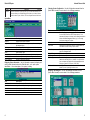
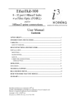
EtherHub-16mi+ Advanced Reference Guide EH1502S E0398-R01 150858-101 Copyright © 1998 by Accton Technology Corporation. All rights reserved. No part of this document may be copied or reproduced in any form or by any means without the prior written consent of Accton Technology Corporation. EtherHub-16mi+ Accton makes no warranties with respect to this documentation and disclaims any implied warranties of merchantability, quality, or fitness for any particular purpose. The information in this document is subject to change without notice. Accton reserves the right to make revisions to this publication without obligation to notify any person or entity of any such changes. Intelligent Stackable Multi-segment Ethernet Hub with 16 10BASE-T (RJ-45) ports, 1 10BASE2 (BNC) port, and SNMP agent International Headquarters No. 1 Creation Road III, Science-based Industrial Park Hsinchu 300, Taiwan, R.O.C. Phone: 886-3-5770-270 FAX: 886-3-5770-267 BBS: 886-3-5770-654 Internet: [email protected] USA Headquarters 1962 Zanker Road San Jose, CA 95112 Phone: 408-452-8900 FAX: 408-452-8988 BBS: 408-452-8828 FAST FAX: 408-452-8811 Accton is a trademark of Accton Technology Corporation. Other trademarks or brand names mentioned herein are trademarks or registered trademarks of their respective companies. EH1502S E0398-R01 150858-101 EtherHub 1500 System Advanced Reference Guide Contents Introduction Introduction 1 Making the Connections Required for System Configuration 1 Onsite Connection Modem Connection In-Band Network Connection Starting the Configuration Program Using Configuration Program System Menu Displaying System Information Changing System Configuration Assigning Trap Managers Downloading System Software Restarting the Agent Reverting Configuration to Factory Settings Save Configuration Reset Configuration Control Menu Configuring Hub Parameters Configuring Port Parameters Defining Backup Ports Setting External Configure Buttons Performance Menu Threshold Menu Threshold Parameters Event Activation 1 1 1 2 3 4 4 5 5 6 6 6 6 6 7 7 8 8 9 9 10 10 11 Troubleshooting 11 Pin Assignments for Serial Port Connections 11 Network Management Access DB9 Serial Port Pin Description DB9 Port Pin Assignments DB9 Serial Port to RJ-45 Converter Connector Pin Assignment DB9 PC's COM Port to RJ-45 Converter Connector Pin Assignment DB25 RS232 to RJ-45 Converter Connector Pin Assignment Connection from Hub's 9-Pin Serial Port to PC's 9-Pin COM Port Connection from Hub's 9-Pin Serial Port to Modem's 25-Pin DCE Port Connection from Hub's 9-Pin Serial Port to PC's 25-Pin DTE Port Optional Management Software 11 11 11 12 12 12 12 13 13 13 The master hub (and connected stack) can be managed through a PC or modem connection to the hubs serial port, or with SNMP-based network management software such as AccView/Open. Using the configuration program, you can perform the following tasks: Enable/disable any port Assign backup ports Set threshold values Configure SNMP parameters Display system information or statistics Download system firmware Restart the system Making the Connections Required for System Configuration The diskette included with the EtherHub-16mi+ contains a menu-driven configuration program. To use this program, make a direct PC or modem connection to the serial port on the master hub in the stack. This section describes how to access the menu-driven configuration program via: Onsite connection A workstation connected to the serial port on the hub. Modem connection A workstation connected to the serial port of a remote hub via modems. In-band connection It also describes how to access the embedded SNMP agent over the network using AccView/Open or other third-party network management software. Onsite Connection Attach a PC to the serial port on the master hub. Use the null-modem cable (and DB9 / RJ-45 converters) provided with this package, or use a null modem connection that complies with the wiring assignments shown in the back of this guide. Modem Connection Configure the Hub Site: Connect the master hub's DB9 serial port to the modem's serial port using standard cabling. For most modems, which use a 25-pin port, you will have to provide an RS232 cable with a 9-pin connector on one end and a 25-pin connection on the other end. You do not have to set the modem at the hub's site, because the hub will automatically configure it to auto-answer mode. Configure the Remote Site: At the remote site, connect the PC's COM port (COM 1~4) to the modem's serial port. In-Band Network Connection The EtherHub 1500 sytem can also be managed from a computer using network management software such as AccView/Open. However, prior to accessing the hub, you must first configure it with a valid IP address, subnet mask, and default gateway using an out-of-band connection. 1 EtherHub 1500 System Note: The on-board program only provides access to basic configuration functions. To access the full range of SNMP mangement functions, you must use SNMP-based network mangement software. Accton provides Windows-based SNMP software called AccView/Open with this package. Note that AccView/Opens Hub Manager module can be easily integrated into most third-party management platforms. Advanced Reference Guide 3. If setting up a remote connection via modems: Select Modem Channel to open the Phone List menu as shown below, and enter the phone number and press [Enter] to start the dialing mechanism. Starting the Configuration Program Insert the distribution diskette provided with your EtherHub-16mi+ into the PC's floppy drive.Then activate the EtherHub 1500 System Configuration Program as described below. Note: 1. When using a PCMCIA modem connection, add the following entry to your config.sys file: device=cardtalk.sys /A /Com3IRQ=4. If your PC has a PCMCIA modem or multi-I/O card, set the proper IRQ by typing "EH15SCP/i [irq #]". 2. Help is available by entering "EH15SCP/?". 3. This program can only run under DOS, or in Windows DOS shell. 1. Type "EH15SCP" at the DOS prompt C:\>EH15SCP. Using arrow keys, select the communication port on the workstation that is connected to the hub. Once the connection is established, the main menu for out-of-band configuration appears as shown below. Using Configuration Program The EtherHub 1500 System Configuration Program allows you to define system parameters, manage and control stacked hubs and associated ports, set threshold levels, and monitor network conditions. The following table briefly describes the menu selections available for this program. Menu Syste m 2. Select the appropriate option from the DCE/DTE dialog box: Terminal Channel for local hookup, or Modem Channel for remote connection. 2 Description De fine s d e scrip tio n fo r the syste m. Se ts syste m p arame te rs. Co nfig ure s Co mmunitie s, IP and IPX trap manag e rs. Do wnlo ad s ne w ve rsio n o f firmware to up d ate yo ur syste m. Re starts yo ur syste m. Re ve rts all co nfig uratio n se le ctio ns to facto ry d e fault se tting s. Save s the co nfig uratio n chang e s mad e d uring the curre nt se ssio n. Re sto re the last save d co nfig uratio n. Co ntro l Iso late s/attache s a hub , o r se ts the hub ' s se g me nt.. Disab le s/e nab le s a p o rt.. Se ts up to 3 p airs o f b ackup p o rts. Each p air co ntains a maste r and slave p o rt. The slave p o rt is no rmally d isab le d . Whe n the maste r p o rt fails, the syste m d isab le s the maste r p o rt and e nab le s the slave p o rt to maintain the link. Push b utto n Enab le s/d isab le s Co nfig ure b utto n to p re ve nt unautho rize d use . Pe rfo rmance Pro vid e s 4 sub -me nus - Syste m, Se g me nt, Hub and Po rt. This se le ctio n allo ws yo u to vie w ne two rk p e rfo rmance fo r the se le cte d co mp o ne nt. Pe rfo rmance is me asure d in te rms o f frame s re ce ive d , numb e r o f b yte s, co llisio n rate , CRC e rro rs, alig nme nt e rro rs, and to tal e rro rs. Info rmatio n Co nfig uratio n Trap Manag e rs Do wnlo ad Re start Facto ry Se tting Save Co nfig uratio n Re se t Co nfig uratio n Hub Po rt Backup p o rt - 3 EtherHub 1500 System Menu Thre sho ld Advanced Reference Guide Description (co ntinue d ) Pro vid e s 5 sub -me nus - Syste m, Any Hub , Any Po rt, Se le ct Hub and Se le ct Po rt. This me nu allo ws yo u to se t thre sho ld le ve ls fo r the hub o r p o rt in te rms o f frame s re ce ive d , numb e r o f b yte s, co llisio ns, CRC e rro rs, alig nme nt e rro rs and to tal e rro rs. Changing System Configuration - Use the Configuration command from the System Menu to modify current values for the following parameters: System Menu Menu Description Information Configuration Displays EtherHub system information. Modifies various parameter settings necessary for communicating with the management agent. Selects management stations to receive trap messages from the system. Downloads a binary file to the SNMP agent. Resets the SNMP agent. Reverts all configuration settings to the original factory settings. Saves the configuration changes made during the current session. Restores the last saved configuration. Trap Managers Download Restart Factory Settings Save Configuration Reset Configuration Displaying System Information - Use the Information command to display and modify system information about the EtherHub stack, or for quick system identification. View a description of the system, including: Field Description IP Address IP address of the agent you're managing. The EtherHub system may be run on SNMP protocol over UDP/IP transport protocol. In this environment, all systems on the Internet, such as network interconnection devices and Network Management Stations (e.g., the PC running AccView) are assigned an IP address. Hardware address of EtherHub-16mi+. Subnet mask of the agent you've selected. This mask identifies the host address bits used for routing to specific subnets. Default gateway used in passing trap messages from the EtherHub agent to the management station. For internal use only. For internal use only. The selected format used on the LAN; i.e., type used by the IPX network where the EtherHub-16mi+ is installed. If the specified frame type is not detected, the EtherHub-16mi+ will automatically detect the current type. (Values: 802.3, Ethernet II, SNAP, 802.2) Identifies the IPX network number for the connected slot. You can disable IPX protocol by setting this number to zero. MAC Address Subnet Mask Default Gateway Default NMS NMS-Download File IPX Frame Type IPX Network Number Assigning Trap Managers - Use the Trap Managers command from the System Menu to modify current values for the following parameters: Field Description System Description System Uptime System Name Contact Location Name and version of the EtherHub-16mi+ software. Length of time the EtherHub management agent has been running. Name assigned to the EtherHub system. Contact person for the system. Specifies the area or location where the system resides. 4 5 EtherHub 1500 System Advanced Reference Guide Field Description SNMP Community Names The community strings authorized for trap management access. All community strings used for IP and IPX Trap Managers must be listed in this table. A community entry authorized for trap management access. Management access is restricted to read-only (RO) or read/write (RW). The status of the current entry can be set to VALID or INVALID. IP management stations selected to receive trap messages from the system. IP address of the management station. The community string required for trap management access. The status of the current entry can be set to VALID or INVALID. IPX management stations selected to receive trap messages from the system. Identifies the IPX network number for the connected slot. MAC address of the authorized trap manager. The community string required for trap management access. The status of the current entry can be set to VALID or INVALID. Community Name Access Status IP Trap Managers IP Address Community Name Status IPX Trap Managers Net Number Node ID Community Name Status Control Menu Menu Description Hub Includes hub description and commands to isolate/reattach network connection, or assign hub to a specified segment. Includes port description and command to enable/disable selected port. Defines master/slave port pairs used for emergency backup. Enables/disables external Configure button on selected hub. Port Backup Port Push Button Configuring Hub Parameters - Use the Hub command from the Control menu to configure any hub in the stack. (Select the required hub using the <F4> and <F5> function keys.) This menu provides a brief description of the selected hub, and also allows you to isolate/reattach the hub from the network. Downloading System Software - Use the Download command from the System Menu to load available software updates into the agent's flash ROM. The download file should be an EtherHub binary file from Accton Technology Corporation; otherwise the agent will not accept it. Invoking this command brings up the Download dialog box. When all entries are confirmed, the display will change to show the progress of the download process. After downloading the new software, the agent will automatically restart itself. The following describes each entry in the dialog box: Field Description Hub ID Hub identifier within the stack. (Up to 10 hubs may be connected via the management channel.) Note that hub IDs can only be assigned using the Configure button as described in the Quick Installation Guide. The physical position in the stack. Any user-defined name for the selected hub. The stack connection may be set to ISOLATED or ATTACHED. Note that the Isolated LED will be lit if the hub is isolated. (Although the status of OTHER is provided, this is for internal use only.) Attach the hub to a specified segment. The appropriate Segment icon will light up to show that the hub has been connected. Indicates hub type as EH1501S, or EH1502S (Master or Slave). Indicates the current firmware version number. Position Name Status Field Description Timeout Retry Filename Transferred Block Total Blocks Time to wait for a response. Number of attempts to make contact. The binary file to download. Current number of data block being transferred. Total number of blocks to transfer. Segment Type Firmware Ver. Restarting the Agent - Use the Restart command from the System menu to reset a selected agent. LEDs on the agent will light up sequentially as it executes the initialization test. Reverting Configuration to Factory Settings - Use the Factory Settings command from the System menu to change all configuration settings back to the factory defaults. Save Configuration - Saves configuration settings made during current session. Reset Configuration - Restores configuration settings saved the last time. 6 7 EtherHub 1500 System Advanced Reference Guide Configuring Port Parameters - Use the Port command from the Control menu to configure the ports for any hub in the stack. (Select the required hub using the <F4> and <F5> function keys.) This menu provides a brief description of the selected hub, and also allows you to enable/disable any port in the selected hub. Field Description Slave Port Hub Port Pair member serving as the backup link. Hub ID for the slave port. Port identifier for the slave port. (continued) Setting the External Configure Buttons - Use the Push Button command in the Control Menu to disable or enable the Configure button on any hub. Performance Menu Field Description Hub ID Position Port Identifier Name Type Status Part Link State Hub identifier within the stack. The physical position in the stack. Numeric identifier 1~16 or ALT. User-defined name for selected port. Connection types include 10BASE-T (RJ-45), BNC, AUI or FIBER. Any port may ENABLED or DISABLED. Indicates if the port is partitioned. Indicates if the port has a valid connection to an external device. Displays statistics for the System (entire stack), selected Segment, selected Hub, or all Ports on a specified hub. (Select any segment or hub using the <F4> and <F5> function keys.) Defining Backup Ports - Use the Backup Port command in the Control Menu to define up to three master/slave port pairs. If the connection to the master port fails, the slave port will automatically take over. Field Description Backup Set Defines up to three backup port pairs; each of which can be set to ACTIVE or INACTIVE. Pair member serving as the primary link. Hub ID for the master port. Port identifier for the master port. Master Port Hub Port 8 Menu Description Frames Bytes Collisions Allignment Errors CRC Errors Number of frames passing through this device. Number of bytes passing through this device. Number of simultaneous node transmissions detected by this device. Number of mis-synchronized data packets detected by this device. Number of Ethernet Cyclic Redundancy Check errors detected by this device. Total number of errors, including FCS, allignment, Frames Too Long, Short Events, Late Events, Jabber, and Data Rate Mismatches detected on this device. Total Errors 1: The values displayed have been accumulated since the last system reboot or counter reset. 9 EtherHub 1500 System Advanced Reference Guide Threshold Menu Select the Threshold command from the menu bar to define limits for the parameters monitored by the hub system. Limits can be set for the System (entire stack), Any Hub or Any Port, or a Select Hub or Select Port. Variables to monitor include frames, bytes, collisions, frame allignment errors, CRC errors or total errors. High and low watermarks may be set. While the trigger action includes warning, warning and isolate (for hubs), or warning and disable (for ports). When any threshold is exceeded, the agent will issue an alarm to the network management station based on the selected action. Event Activation - After initial event activation (crossing the high watermark), the monitored variable must reach the low watermark before another event is activated (again crossing the high watermark). T: triggered N: not triggered H T N T L Notes: 1. The rate for all values is per one second. 2. Threshold entries are stored in the agent. Troubleshooting Refer to the Quick Installation Guide for a more detailed listing of troubleshooting procedures. However, if you have trouble making a connection via SNMP network management software, then please refer to the following section. Network Management Access To set thresholds: 1. Open the Threshold dialog box from the menu bar. 2. Select the system component (Type: System, Any Hub, Any Port, Select Hub, Select Port). If you choose Select Hub or Select Port, then choose the Hub ID or Port ID using the <F2> function key. 3. Select the variable to monitor (Variable: Frames, Bytes, Collisions, Allignments, CRCs or Total Errors). If you choose Select Hub or Select Port, then choose the variable Type using the <F2> function key. 4. Input an integer value for the low and high watermarks. You can access the EtherHub-16mi+ from anywhere within the attached network. However, you must first configure it with a valid IP address, subnet mask, and default gateway. If you have trouble establishing a link to the SNMP agent (with network management software such as AccView/Open), check to see if you have a valid network connection. Then verify that you entered the correct IP address from your location. Also, be sure the port through which you are connecting to the hub has not been disabled. (See the Control Menu on page 7.) If it has not been disabled, then check the network cabling that 1 runs between your management site and the stack. 5. Select the appropriate action (Action: INACTIVE, WARNING, WARNING & ISOLATE for hubs, or WARNING & DISABLE for ports). Pin Assignments for Serial Port Connections 6. Implement your settings by pressing the <F3> function key. DB9 Serial Port Pin Description Threshold Parameters - Hub/Port parameters include the following items: 9 The DB9 serial port on the back panel is used to connect the hub to a management device. The configuration program can be accessed from a PC, or from a remote location via a modem connection. You can use the management port to configure port settings (e.g., enabled or disabled), or to update device firmware. The pin assignments used to connect various device types to the hub's management port are provided in the following tables. DB9 Port Pin Assignments Parameter Description Frame Bytes Collisions The total number of frames. The total number of bytes. Multiple packets transmitted over a medium at the same time, making them unintelligible. Frame alignment errors occur when the received frame is a multiple of 8 bits. This error occurs when the cyclic redundancy check for a frame is wrong. (The cyclic redundancy check an error-checking algorithm used to indicate frame reception errors.) The total number of collisions, frame alignment errors and CRC errors. Alignments CRCs Total Errors 10 EI A Circuit CCITT Signal CF BB BA CD AB CC CA CB CE 109 104 103 108.2 102 107 105 106 125 Description Hub's DB9 DTE Pi n # DCD (Data Carrie r De te cte d ) 1 RxD (Re ce ive d Data) 2 TxD (Transmitte d Data) 3 DTR (Data Te rminal Re ad y) 4 SG (Sig nal Gro und ) 5 DSR (Data Se t Re ad y) 6 RTS (Re q ue st-to -Se nd ) 7 CTS (Cle ar-to -Se nd ) 8 RI (Ring Ind icato r) 9 PC DB9 DTE Pi n # 1 2 3 4 5 6 7 8 9 Modem DB25 DCE Pi n # 8 3 2 20 7 6 4 5 22 Signal Direction DTE-DCE <--------<-----------------> ---------> --------<-----------------> <--------<--------- 11 EtherHub 1500 System Advanced Reference Guide DB9 Serial Port to RJ-45 Converter Connector Pin Assignment Description DTR (Data Te rminal Re ad y) 1 RxD (Re ce ive d Data) 2 TxD (Transmitte d Data) 3 SG (Sig nal Gro und ) 4 RI (Ring Ind icato r) 5 CTS (Cle ar-to -Se nd ) 6 RTS (Re q ue st-to -Se nd ) 7 DCD (Data Carrie r De te cte d ) 8 DSR (Data Se t Re ad y) NC RJ-45 Pin Mapping 4 2 3 5 9 8 7 1 6 DB9 PC's COM Port to RJ-45 Converter Connector Pin Assignment Description DTR (Data Te rminal Re ad y) 1 RxD (Re ce ive d Data) 2 TxD (Transmitte d Data) 3 SG (Sig nal Gro und ) 4 RI (Ring Ind icato r) 5 CTS (Cle ar-to -Se nd ) 6 RTS (Re q ue st-to -Se nd ) 7 DCD (Data Carrie r De te cte d ) 8 DSR (Data Se t Re ad y) NC RJ-45 Pin Mapping 6 3 2 5 9 7 8 1 4 DTR (Data Te rminal Re ad y) 1 RxD (Re ce ive d Data) 2 TxD (Transmitte d Data) 3 SG (Sig nal Gro und ) 4 RI (Ring Ind icato r) 5 CTS (Cle ar-to -Se nd ) 6 RTS (Re q ue st-to -Se nd ) 7 DCD (Data Carrie r De te cte d ) 8 DSR (Data Se t Re ad y) NC RJ-45 Pin Mapping 1 2 3 4 5 6 7 8 9 EH1502S DB25 20 3 2 7 22 5 4 8 6 Hub's 9-Pin Serial Port CCITT Signal <------ DCD ------<------ RXD -------------- TXD ------> -------- DTR ------> -------- SGND ----<------ DSR -------------- RTS ------> <------ CTS ------<------ RI ------- Modem's 25-Pin COM Port 8 3 2 20 7 6 4 5 22 Connection from Hub's 9-Pin Serial Port to PC's 25-Pin DTE Port Hub's 9-Pin Serial Port 1 DCD 2 RXD 3 TXD 4 DTR 5 SGND 6 DSR 7 RTS 8 CTS 9 RI EH1502 DB9 DB25 RS232 to RJ-45 Converter Connector Pin Assignment Description Connection from Hub's 9-Pin Serial Port to Modem's 25-Pin DCE Port EH1502S DB9 Null Modem 1 1 2 3 3 2 4 8 5 20 6 7 7 4 9 5 20 6 PC's 25-Pin DTE Port 8 DCD 3 TXD 2 RXD 20 DTR 7 SGND 6 DSR 4 RTS 5 CTS 22 RI Optional Management Software SW6120: SW6121: SW6122: SW6122: SW6130: SW7300: AccView EtherHub Manager for SunNet Manager AccView EtherHub Manager for OpenView/Windows AccView EtherHub Manager for OpenView/Unix AccView EtherHub Manager for NMS Network Mangement Support Modules for NMM EtherHub 1500 Security Module Connection from Hub's 9-Pin Serial Port to PC's 9-Pin COM Port Hub's 9-Pin Serial Port 1 DCD 2 RXD 3 TXD 4 DTR 5 SGND 6 DSR 7 RTS 8 CTS 9 RI 12 PC's 9-Pin COM Port ------- DCD -------- 1 <----- TXD --------- 3 ------- RXD ------> 2 ------- DSR ------> 6 ------- SGND ------ 5 ------- DTR -------- 4 ------- CTS ------> 8 <------ RTS -------- 7 ------- RI ----------- 9 CCITT Signal 13