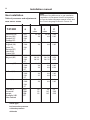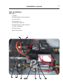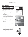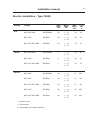
1
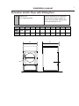
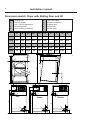
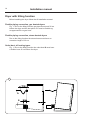
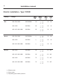
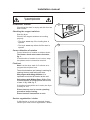
Installation manual
Tumble dryer
T4900, T41200
487 05 46 61.00
EN
Tumble dryer
Installation
manual
Safety instructions
This machine is only intended for drying water-washed
garments.
Clothes that have been cleaned with chemicals/flammable
liquids, must NOT be dried in the machine.
Remove clothes from the dryer as soon as they are dry. This
prevents them from becoming creased, and reduces the risk of
spontaneous ignition.
The machine must not be used for drying foam rubber or foamlike materials.
The machine must not be used for drying floor mops*.
The machine must not be used by minors.
The machine must not be hosed down with water.
The machine must not be installed or stored in an area where it
will be exposed to water and/or weather.
Mechanical, electrical and gas installations and service must
only be carried out by qualified personnel.
Report machine malfunctions to qualified service personnel as
soon as possible. This is important for your own safety and for
the safety of others.
Gas dryers only:
The machine is not to be installed in rooms containing cleaning
machines with perchloroethylene, TRICHLOROETHYLENE or
CHLOROFLUOROCONTAINING HYDROCARBONS as cleaning
agents.
What to do if you smell gas:
Do not try to light any appliance.
Do not touch any electrical switch; do not use any phone in
your building.
Evacuate the room, building or area.
Contact the laundry manager.
*Applies only to floor mops containing polypropylene.
The dryer must not be installed behind a lockable door or a
sliding door. In the rooms where the dryer is to be installed the
door hinges must be on the outer side.
3
Installation manual
Contents
Dimension sketch . . . . . . . . . . . . . . . . . . . . . . . . . . . . . . . . . . . . . . . . . . 6
Technical data . . . . . . . . . . . . . . . . . . . . . . . . . . . . . . . . . . . . . . . . . . . . 9
Setup. . . . . . . . . . . . . . . . . . . . . . . . . . . . . . . . . . . . . . . . . . . . . . . . . . . 12
Dryer with tilting function. . . . . . . . . . . . . . . . . . . . . . . . . . . . . . . . . . . . 14
Mechanical installation . . . . . . . . . . . . . . . . . . . . . . . . . . . . . . . . . . . . . 15
Exhaust system. . . . . . . . . . . . . . . . . . . . . . . . . . . . . . . . . . . . . . . . . . . 17
Steam installation . . . . . . . . . . . . . . . . . . . . . . . . . . . . . . . . . . . . . . . . . 18
Gas installation . . . . . . . . . . . . . . . . . . . . . . . . . . . . . . . . . . . . . . . . . . . 19
Electrical installation . . . . . . . . . . . . . . . . . . . . . . . . . . . . . . . . . . . . . . . 24
Function check . . . . . . . . . . . . . . . . . . . . . . . . . . . . . . . . . . . . . . . . . . . 27
Options: Dimension sketch - Adaptor for direct fresh-air intake . . . . . . 28
The manufacturer reserves the right to modify design and
material specifications without notice.
5
6
Installation manual
Dimension sketch. Dryer with standard loading door
1
2
5
6
7
8
9
Heating unit
Delivery height
excl. 100 mm packaging
Operating panel
Door opening, Ø 940 mm
3
4
Gas connection
Electric connection
Exhaust duct
Steam inlet
Steam return
A
B
C(a)
C(b)
C(c)
D
E
F
G
H
4900
1290
1307
2465
1965
500
850
790
230
245
1590
41200
1290
1497
2465
1965
500
850
790
230
245
1590
J
K
L
M
N
P
Q
R
S
T
4900
165
180
2055
410
530
2400
1868
2350
2060
41200
165
180
2055
410
530
2590
1868
2350
2060
P
B
A
1
C
(c)
2
3
C C
(a) (b) Q
4
D
N
M
K
All measurements in mm
8
9
5
J
E
6
J
Gas
Gas
K
6
J
K
6
Steam
Damp
Electric
El.
R
L
S
H
H
7
F
H
7
G
F
7
G
F
G
Installation manual
Dimension sketch. Dryer with Sliding Door
10
Sliding Door
Door opening Ø 940
Where nothing else is mentioned
the dimension sketch applies to
“Dryer with standard loading door”
All measurements in mm
U
V
4900
1314
1270
41200
1314
1460
U
10
V
7
8
Installation manual
Dimension sketch. Dryer with Sliding Door and tilt
1
2
5
6
7
8
9
Heating unit
Delivery height
excl. 100 mm packaging
Operating panel
Door opening, Ø 940 mm
3
4
Gas connection
Electric connection
Exhaust duct
Steam inlet
Steam return
A
B
C(a)
C(b)
C(c)
D
4900
1314
1270
2545
2045
500
41200
1314
1460
2545
2045
J
K
L
4900
165
180
41200
165
180
E
F
G
H
930
230
330
1670
500
930
230
330
1670
M
N
P
Q
R
S
2130
410
530
1540
2660
2425
2130
2130
410
530
1740
2680
2425
2130
A
P
1
C
(c)
2
B
Q
C C
(a) (b)
3
4
D
N
M
8
9
5
J
K
6
J
Gas
Gas
K
6
J
K
6
Steam
Damp
Electric
El
R
S
L
H
H
7
H
7
F
G
F
7
G
F
G
9
Installation manual
Technical data - type T4900
Heating
Gas
Cylinder volume:
Weight net:
Cylinder:
900 litres
900 litres
Basic machine
440 kg
440 kg
440 kg
with Sliding Door
494 kg
494 kg
494 kg
with Sliding Door and tilt
546 kg
546 kg
546 kg
Heating unit
39 kg
50 kg
42 kg
Tilting unit
66 kg
66 kg
66 kg
1240 mm
1240 mm
1240 mm
770 mm
770 mm
770 mm
38 rpm
38 rpm
38 rpm
45 kg
45 kg
45 kg
Diameter
Revolutions per minute
Capacity:
Gas heating
64 kW
Steam heating
Depending upon
steam pressure
Electric heating
Air consumption:
Piping:
Electric
900 litres
Depth
Heat effect:
Steam
Exhaust duct
Gas connection
48 / 60 kW
Max. 2300 m3/h
Max. 2300 m3/h
Max. 2300 m3/h
Ø 315 mm
Ø 315 mm
Ø 315 mm
ISO 7/1 - R1
Steam in
ISO 228/1 - G1
Steam out
ISO 228/1 - G1
Pressure drop:
max. 100 Pa
max. 100 Pa
max. 100 Pa
< 70 dB (A)
< 70 dB (A)
< 70 dB (A)
Gas pressure: See page regarding pressure
Sound pressure level:
10
Installation manual
Technical data - type T41200
Heating
Gas
Cylinder volume:
Weight net:
Cylinder:
1200 litres
1200 litres
Basic machine
470 kg
470 kg
470 kg
with Sliding Door
524 kg
524 kg
524 kg
with Sliding Door and tilt
576 kg
576 kg
576 kg
Heating unit
46 kg
50 kg
42 kg
Tilting unit
66 kg
66 kg
66 kg
Diameter
1240 mm
1240 mm
1240 mm
Depth
1000 mm
1000 mm
1000 mm
38 rpm
38 rpm
38 rpm
60 kg
60 kg
60 kg
Capacity:
Gas heating
82 kW
Steam heating
Depending upon
steam pressure
Electric heating
Air consumption:
Piping:
Electric
1200 litres
Revolutions per minute
Heat effect:
Steam
Exhaust duct
Gas connection
60 / 72 kW
Max. 3000 m3/h
Max. 3000 m3/h
Max. 3000 m3/h
Ø 315 mm
Ø 315 mm
Ø 315 mm
ISO 7/1 - R1
Steam in
ISO 228/1 - G1
Steam out
ISO 228/1 - G1
Pressure drop:
max. 100 Pa
max. 100 Pa
max. 100 Pa
< 70 dB (A)
< 70 dB (A)
< 70 dB (A)
Gas pressure: See page regarding pressure
Sound pressure level:
Installation manual
Technical data - motor specifications - T4900, T41200
Blower motor 3-phase:
Effect:
Revolutions per minute:
1.1 kW
50 Hz
2800 rpm
60 Hz
3400 rpm
Drum motor 3-phase:
Effect:
Revolutions per minute:
1.5 kW
50 Hz
1440 rpm
60 Hz
1730 rpm
11
12
Installation manual
1
Unpacking
Place the dryer in its place before unpacking it.
When unpacking the dryer, handle it with care.
500 mm
Setup
10 mm
10 mm
Positioning
Place the dryer in such a way that work can be
done as easily as possible by the user and the
service technician alike.
The distance to the wall or other equipment
behind the dryer should be min. 500 mm.
However, there should be free access to the
back of the dryer for the purpose of servicing
it.
Fig. 1. Dryer with standard loading door
Fig. 2. Dryer with Sliding Door and tilt
Apart from the minimum distances shown on
fig. 2 there are no further requirements to the
distance around the dryer.
2
500 mm
Apart from the minimum distances shown on
fig. 1 there are no further requirements to the
distance around the dryer.
100 mm
50 mm
Installation manual
Removal from transportation pallet
1
1. Demount back plates and filter door.
2. Knock the two wood boards loose, one in front
and one in the back, with a hammer, fig. 1.
3. Demount the 4 screws holding the bars.
4. Lift the dryer with pallet truck or fork-lift truck
and remove the bars.
5. Mount the four feet in the bottom bearers, fig. 2.
6. T41200 only.
When pallet truck or fork-lift truck is removed the
2 steel sections are disengaged.
Remove steel sections and the remainder from
transportation pallet.
2
13
14
Installation manual
Dryer with tilting function
Before installing the dryer follow the tilt installation manual.
Flexible piping connection, gas heated dryers
Fig. 1. Due to the tilting function gas pipe A must end 30 cm
before the dryer and the last piece of it must be flexible eg.
an approved 60 cm gas hose.
Flexible piping connection, steam heated dryers
Due to the tilting function the steam hoses must have an
excessive length of 30 cm.
Outlet duct, all heating types
Fig. 1. Due to the tilting function the outlet duct B must have
a flexible hose 20 cm before the dryer.
1
30 cm
A
B
20 cm
15
Installation manual
1
Mechanical installation
Adjust the dryer to ensure that it is horizontal
and stands firmly on all four feet (the height
adjustment must be as low as possible), fig. 1.
The maximum height adjustment of the feet is
70 mm and is only to be used cautiously while
removing lifting truck or fork truck.
Heating unit
The heating unit is to be mounted on top of the
dryer.
During transport the top plate for the heating
unit is placed on top of the dryer.
Equally during transport the two side panels and
the bracing bar A are placed in the back of the
dryer, fig. 2.
See the installation manual for the heating
unit.
Transportation fittings
2
During transport the transmission is secured.
Remove the transportation securing B by
cutting the strips, fig. 2.
B
A
16
Installation manual
Exhaust system
1
Air principle
The blower creates low pressure in the dryer,
drawing air into the cylinder via the heating
unit.
The heated air passes through the garments
and the cylinder vents.
The air then flows out through a lint filter
positioned immediately below the drum. After
this, the air is evacuated through the blower
and exhaust system, fig. 1.
It is very important that the dryer gets enough
fresh air, see next section.
Fresh-air
For maximum efficiency and the shortest
possible drying time, it is important to ensure
that fresh air is able to enter the room from the
outside in the same volume as that blown out
of the room.
To avoid a draught in the room, it is advisable
to place the air inlet behind the dryer.
The area* of the air inlet opening must be 5
times the size of the exhaust pipe area, fig. 2.
See table on the following page.
The resistance in the grating/slats on the air
inlet cover plate should not exceed 10 Pa
(0.1 mbar).
2
A
5xA
The air consumption is maximum:
T4900: 2300 m3/h.
T41200: 3000 m3/h.
Note! Gratings/slatted covers often block half
of the total fresh air vent area. Remember to
take this into account, fig. 3.
*The area of the inlet opening is the area
through which the air can flow without
resistance from grating/slatted cover.
3
5xA
17
Installation manual
Exhaust system
Exhaust duct
1
It applies to the exhaust duct that:
• The exhaust duct must be smooth on the
inside (low air resistance).
• The exhaust duct must lead into the open.
• The exhaust duct must lead clear of the
building as condensation may cause
frost damage to the building.
• The exhaust duct must be protected against
rain and foreign objects.
• The exhaust duct must have gentle bends,
fig. 2.
2
• The exhaust duct must not be a shared duct
between dryers and appliances using gas or
other fuels as their energy source.
It applies to the installation of several dryers
on a shared exhaust duct that:
• The exhaust duct diameter must increase after
each dryer, fig. 1.
The table below shows the exhaust duct
diameter and the necessary fresh-air
inlet area.
• The exhaust duct must have a nonreturn flap
after each dryer.
Note! It is recommended that each dryer is
connected to a separate exhaust duct.
Service organization/dealer
If you have questions relating to the design of
the exhaust system, please contact your local
dealer or service organization.
The exhaust duct
diameter must not
be reduced.
No. of dryers
1
2
3
4
5
6
7
8
Air outlet pipe
diameter in mm
315
450
560
630
710
800
800
900
Required area of
fresh-air inlet
in m2
0.4
0.8
1.2
1.6
2.0
2.4
2.8
3.2
Each dryer requires a fresh-air aperture of min. 624 x 624 mm
18
Installation manual
Steam installation
1
Before start
The steam supply must be cut off and must not
be under pressure.
Steam
a
D
b
Steam 3-10 bar absolute pressure
(130 - 180°C).
E
Steam forward
1. The branch pipe’s branch must be located
at the top of the main steam pipe to prevent
condensation in the steam.
b c
2. The branch pipe must have a descending
gradient and must end at a height above the
inlet connecting branch (D).
a
3. Mount a shut-off valve (a) and a strainer (b) in
the branch pipe, fig. 1.
Condensation return
1. It is important that the branch pipe for
condensed water on return to the main
condensate pipe has a descending gradient and
is lower than the outlet connecting branch (E).
2. Mount a strainer (b) in the return pipe.
3. Mount a steam trap behind the dirt collector (c).
2
4. Then mount a shut-off valve (a).
5. Mount pressure hoses between branch pipes
and dryer (hoses are not supplied), fig. 1.
6. The pressure hoses must not hang down, fig. 2.
Leak test
1. Leak test the system.
2. Clean the dirt collectors (b).
Function check
The function check is described in the back of
this manual.
Pipe insulation
All pipes must be insulated in order to reduce
risk of burning. Insulation also reduces loss of
heat to the surroundings.
Note
Before installing dryer with tilt
see section “Dryer with tilting
function”.
19
Installation manual
Gas installation
To be carried out by
qualified personnel
Install a manual gas shutoff valve upstream
from the dryer.
The gas connection to the dryer should be
dimensioned to an output depending upon the
kW-rating of the dryer.
1
A
The factory nozzle pressure setting must
correspond to the fuel value given on the data
label.
Check that the nozzle pressure and fuel value
agree with the values given in the table. If not,
contact your gas supplier.
Bleed the pipe system before connecting the
dryer.
After connection, test all joints for leaks.
Test run
Note! To ensure the correct amount of air to
the combustion, plate A must be mounted
before starting the dryer.
Loosen the measuring branch screw (2) 1/4 of
a turn.
Connect a manometer to the measuring branch
(2), (See page regarding gas valve).
Fill garments into the drum.
Select a programme that uses heat.
Start the dryer.
Check the nozzle pressure, see table.
If necessary, adjust the setting screw (4) of the
regulator under the cover screw (3).
Check that the gas is burning evenly and with a
bluish flame.
Function check
The function check is described in the back of
this manual.
Note
Before installing dryer with tilt
see section “Dryer with tilting
function”.
20
Installation manual
Gas installation
Converting to bottled gas / natural gas
If the dryer is to be converted to another gas type, the gas
nozzles must be replaced.
1. Remove nozzles (pos.1).
2. Mount the supplied nozzles.
3. Dismount plate with ignition electrode (pos. 7).
4. Carefully dismount flame sensor (pos. 8).
5. T41200: Dismount both cover plates (pos. 9+10).
6. T41200: Mount the supplied cover plates.
7. Remount pos. 7 and pos. 8.
Mount the heating unit on the dryer as described in the
installation manual for the heating unit.
The numbers in brackets refer to the page regarding the gas
valve.
Test run
Re. test run see earlier in this section.
Affixing the sign
Place the label with the right country code on the gas label as
shown below. See fig. 1.
Qn (Hs)
40 kW
DK,NO,SE,FI,GB,ES,GR,IE,IT,PT,AT: I2H -20 MBAR
DE: l2E(LL) -20 MBAR
PIN No. 359BO379
MANIF.PRESSURE: 8 MBAR, INJECTOR:Ø5,60 MM
NATURAL GAS: G20 -20 MBAR
(INLET PRES: 20 MBAR, CAL. VAL. 37400 KJ/M3)
1
Får ej övertäckas
Do not cover
Nicht überdecken
Ne pas couvrir
Må ikke overdækkes
Ei saa peittää
Non coprire
487 19 69 74.00
GB Disconnect from the supply before opening.
GB
FR Mettre hors circuit avant d'enlever ce couvercle.
IT
Note! Gas heating.
This bac k plate must be mounted bef ore the dr yer is
star ted (due to v entilating conditions)
Staccare le connessioni elettriche prima di aprire.
DE Strom unterbrechen bevor dieser Deckel geöffnet wird.
FR
DK Afbryd strømmen før dette dæksel fjernes.
SE
Bryt strömmen innan detta lock borttages.
FI
Virta on katkaistava ennenkuin kantta avataan.
DE
IT
ES
487 19 69 15.00
Note! Chauff age au gaz.
La plaque arr ière doit être installée ava nt de démarre r
le séchoir (en raison des conditions de v entilation).
Hinweis! Gasheizung.
Die Rüc kwand muss v or dem Einschalten des
Trockners montie rt worden sein
(wegen der Luftv erhältnisse).
Nota! Riscaldamento a gas .
Montare il pannello poster iore pr ima di a vviare
l’asciugatr ice (a causa delle condizioni di v entilazione).
¡Nota! Calentamiento por gas .
La placa poster ior debe montarse antes de poner
en marcha la secadora (debido a las condiciones de
ventilación).
DK
Bemær k! Gas opv ar mning.
Denne bagplade skal være monteret fø
star tes (p .g.a. luftf orhold).
FI
Huomautus: Kaasulämmitys .
Tämä takale vy pitää asentaa ennen kuiv aajan
käynnistämistä (oik ean ilman vaihdon varmistamiseksi).
r tumblere n
487 22 26 49.00
WARNING
PLUMBERS BEWARE WHEN PRESSURE
TESTING!!!
DRYER MUST NOT BE SUBJECTED TO
PRESSURE THAT EXCEEDS
1/2 psig (3.5kPa).
TO DO SO WILL CAUSE GAS LEAKS
WHICH CAN RESULT IN FIRE OR
EXPLOSION.
TO PROVIDE ADEQUATE COMBUSTION
AIR THE FRESH AIR INTAKE MUST BE
INSTALLED ACCORDING TO
THE INSTALLATION MANUAL.
487 22 26 52.00
GB Disconnect from the supply before opening.
FR Mettre hors circuit avant d'enlever ce couvercle.
IT
Staccare le connessioni elettriche prima di aprire.
DE Strom unterbrechen bevor dieser Deckel geöffnet wird.
DK Afbryd strømmen før dette dæksel fjernes.
SE
Bryt strömmen innan detta lock borttages.
FI
Virta on katkaistava ennenkuin kantta avataan.
487 19 69 15.00
21
Installation manual
Note
Because of the differences in gas installation
regulations in European Union it is important
to use the Italian-language manual in Italy and
the French-language manual in France ect.
Gas installation
Table of pressures and adjustments
Heat effect: 64 kW
T4900
a
Denmark (DK)
Norway (NO)
Sweden (SE)
Finland (FI)
Italy (IT)
England (GB)
Spain (ES)
Portugal (PT)
Ireland (IR)
Greece (GR)
France (FR)
Belgium (BE)
LPG
GNH
GNL
GT
LPG
GNH
GNL
GT
d
mbar
mbar
mm
28-30
8.0
2.90
5.00
28-30 / 37
20
28-30 / 37
8.0
2.90
5.00
LPG
GNH
GNL
GT
LPG
GNH
GNL
GT
LPG
GNH
GNL
GT
LPG
GNH
GNL
GT
28-30 / 37
20 / 25
20 / 25
28-30 / 37
20 / 25
20 / 25
2.90
4.00
4.00
30 , 50
20
20
30
8.0
8.0
2.90
5.00
5.50
28 - 30
20
25
30
8.0
8.0
2.90
5.00
5.50
50
20
30
8.0
2.90
5.00
LPG
GNH
GNL
GT
30
18
18
30
8.0
8.0
2.9
5.0
5.5
Holland (NL)
Austria (A)
a=Gas type
b=Connection pressure
c=Nozzle pressure
d=Nozzle
c
28-30
20
Germany (DE)
The rest of
the world
except:
Australia, USA,
New Zealand
b
22
Installation manual
Note
Because of the differences in gas installation
regulations in European Union it is important
to use the Italian-language manual in Italy and
the French-language manual in France ect.
Gas installation
Table of pressures and adjustments
Heat effect: 82 kW
a
T41200
b
mbar
Denmark (DK)
Norway (NO)
Sweden (SE)
Findland (FI)
Italy (IT)
England (GB)
Spain (ES)
Portugal (PT)
Ireland (IR)
Greece (GR)
France (FR)
Belgium (BE)
Germany (DE)
Holland (NL)
Austria (A)
The rest of
the world
except:
Australia, USA
New Zealand
LPG
GNH
GNL
GT
LPG
GNH
GNL
GT
d
mbar
mm
28-30
20
28-30
8.0
3.30
5.65
28-30 / 37
20
28-30 / 37
8.0
3.30
5.65
LPG
GNH
GNL
GT
LPG
GNH
GNL
GT
LPG
GNH
GNL
GT
LPG
GNH
GNL
GT
28-30 / 37
20 / 25
20 / 25
28-30 / 37
20 / 25
20 / 25
3.30
4.70
4.70
30 , 50
20
20
30
8.0
8.0
3.30
5.65
6.30
28 - 30
20
25
30
8.0
8.0
3.3
5.65
6.30
50
20
30
8.0
3.3
5.65
LPG
GNH
GNL
GT
30
18
18
a=Gas type
b =Connection pressure
c =Nozzle pressure
d =Nozzle
c
30
8.0
8.0
3.3
5.65
6.30
23
Installation manual
Gas installation
Gas valve
1. Nozzle
2. Measuring tap, nozzle pressure
3. Cover screw
4. Adjusting screw
5. Controlbox, gasvalve
6. Measuring tap, supply pressure
7. Ignition electrode
8. Flame sensor
9+10. Cover plates
8
9
7
10
1
3+4
2
6
5
24
Installation manual
Electric installation
To be carried out by
qualified personnel
1
The tumble dryer must be connected to its
own fuse group / circuit breaker group and
main switch according to IEC 60947.
Cable dimension
For calculation of the connection cable
dimension, please refer to local guidelines.
C
Connecting the cable
1. Demount back plate C with supply
disconnector grip, fig. 1.
2. Lead cable through the cable gland to the
supply disconnector, fig. 2.
3. Connect cable as illustrated. If there is a
neutral conductor it must be connected to
terminal N, fig. 3.
2
Wiring diagrams
D
Wiring diagrams for all heating types are
enclosed the drum.
Wiring diagrams for the specific dryer are in
plastic bag D.
Circuit breaker / effect
The sizes of the circuit beaker and the effect
are shown on the following page.
Function check
The function check is described in the back of
this manual.
(NB: Correct direction of rotation is important!)
3
L3
The tumble dryer must be equipped with
supplementary protection in accordance
with heavy current regulations.
L2
L1
N
25
Installation manual
Electric installation - Type T4900
Heating
Voltage
Gas
200 / 230 / 240V
Heat
effect
kW
3AC 50/60Hz
64
Motor
effect
kW
Max.
effect
kW
1.1
1.5
3.3
20
1.1
1.5
3.3
16
1.1
1.5
3.3
16
1.1
1.5
3.3
20
1.1
1.5
3.3
16
1.1
1.5
3.3
16
1.1
1.5
51
160
1.1
1.5
51
80
1.1
1.5
51
80
1.1
1.5
63
100
1.1
1.5
63
100
1)
2)
400 / 415V
3AC 50Hz
64
1)
2)
400 / 415 / 440 / 480V
3AC 60Hz
64
1)
2)
Steam
200 / 230 / 240V
3AC 50/60Hz
3)
1)
2)
400 / 415V
3AC 50Hz
3)
1)
2)
400 / 415 / 440 / 480V
3AC 60Hz
3)
1)
2)
Electric
230 / 240V
3AC 50/60Hz
48
1)
2)
400 / 415V
3AC 50Hz
48
1)
2)
400 / 415 / 440 / 480V
3AC 60Hz
48
1)
2)
400 / 415V
3AC 50Hz
60
1)
2)
400 / 415 / 440 / 480V
3AC 60Hz
60
1)
2)
1)
= Blower motor
2)
= Drum motor
3)
= Depending upon steam pressure
Fuse
size
A
26
Installation manual
Electric installation - Type T41200
Heating
Gas
Voltage
200 / 230 / 240V
Heat
effect
kW
3AC 50/60Hz
82
Motor
effect
kW
1)
2)
400 / 415V
3AC 50Hz
82
1)
2)
400 / 415 / 440 / 480V
3AC 60Hz
82
1)
2)
Steam
200 / 230 / 240V
3AC 50/60Hz
3)
1)
2)
400 / 415V
3AC 50Hz
3)
1)
2)
400 / 415 / 440 / 480V
3AC 60Hz
3)
1)
2)
Electric
400 / 415V
3AC 50Hz
60
1)
2)
400 / 415 / 440 / 480V
3AC 60Hz
60
1)
2)
400 / 415V
3AC 50Hz
72
1)
2)
400 / 415 / 440 / 480V
3AC 60Hz
72
1)
2)
1)
= Blower motor
2)
= Drum motor
3)
= Depending upon steam pressure
Max.
effect
kW
Fuse
size
A
1.1
1.5
3.3
20
1.1
1.5
3.3
16
1.1
1.5
3.3
16
1.1
1.5
3.3
20
1.1
1.5
3.3
16
1.1
1.5
3.3
16
1.1
1.5
63
100
1.1
1.5
63
100
1.1
1.5
75
125
1.1
1.5
75
125
Installation manual
To be carried out by
qualified personnel
Function check
1
Check that the drum is empty and the door has
been closed.
Checking the magnet switches
Start the dryer.
Check if the magnet switches are working
properly:
• The dryer must stop if the loading door is
opened.
• The dryer must stop when the filter door is
opened.
Correct direction of rotation
Correct direction of rotation on blower wheel:
The blower wheel must rotate clockwise,
fig. 1.
If the direction of rotation is not correct, swop
two phases on the connection terminal.
Final test
Heat: Let the dryer work for 5 minutes on a
program that requires heat.
Then check whether the heating is working by
opening the door and feeling the heat.
Only dryers with tilting function: It is
important to test the tilt function at the end.
Only dryers with Sliding Door: Sliding Door
must be capable of being opened with a force
of max 10 kg / 98N, fig. 2.
If the above tests-points are in order, the dryer
is ready for use.
Please instruct user in correct operating
procedure before leaving.
Please hand all instructions to user.
Service organisation / dealer
If deficiencies or errors are detected, please
contact your local service organisation / dealer.
2
27
28
Installation manual, options
Dimension sketch - Adaptor for direct fresh-air intake
1
Adaptor kit no. 988 800 0003 - Steam heated dryers
2
Adaptor kit no. 988 800 0004 - Gas and electric heated dryers
3
Connecting branch in top / bottom for fresh-air intake, diameter Ø 315 mm
T4900 = 2740
T41200 = 2930
T4900 = 1280
T41200 = 1620
T4900 = 1355
T41200 = 1545
385
3
Dryer with
Sliding Door
Dryer with standard
loading door
2065
2450
(3)
385
230
410
350
2
690
1
www.electrolux.com/professional
Share more of our thinking at www.electrolux.com
about | case studies | contact
0845 077 65 65
Home
Laundry Equipment
Ozone Laundry Systems
Chemicals
Services
Special Offers
Ex Rental
Testimonials
Contact Us