1
DB98_16890A(2)_Co
5/10/04 2:07 PM
Page 1
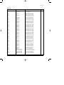
GH052EAM
GH070EAM
CONTENTS
Precautions
1
Product Specifications
2
Operation Instruction & Installation
4
Disassembly and Reassembly
16
Refrigerating Cycle Diagram
27
Feature & Operation
37
Set Up the Model Option
51
Troubleshooting
54
Exploded Views and Parts List
64
Block Diagram
70
PCB Diagram
71
Wiring Diagram
81
Schematic Diagram
84
DB98_16890A(2)_1
5/10/04 2:09 PM
Page 1
1. Precautions
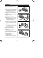
11) Cut off the power.
● Make sure to cut off the power before repair. If not, you may
be damaged by an electric shock.
12) Do not install an outdoor unit on the apartment outside
wall(or equivalent) for safety.
● Installing an outdoor unit on the apartment outside wall(or
equivalent) is prohibited for the safety purpose. Service will
not be available for the outdoor unit where our servicemen
can not access and the cost of moving the outdoor unit to
the service area will be borne by the customer.
● If requested by the customer, you shall discourage him to
install an outdoor unit on the apartment outside wall(or
equivalent).
13) Keep the drain hose outlet free.
● Otherwise, air flow will get slow, which may hinder cooling
capacity.
● Also, dew may be laden on the service valve.
14) Use of Certified Parts
● Use certified parts only. (An electric contact part, if broken
down, shall not be repaired but replaced with a new one.
Remodeling shall be prohibited. In no case, the customer
shall repair the product on his own because this is dangerous enough to bring about breakdown or fire.)
15) Ban on Middle Connection of Power Cord
● Do not cut the power cord in the middle to be connected to
other power cord nor use a middle socket between two
power cords. This is dangerous enough to bring about
breakdown or fire.
16) Check Insulation
● After assembly, be sure to check insulation resistance.
(Use an insulation ohmmeter to measure the insulation
resistance between the power cord and the earthing wire.
Do not supply power until it reads 30MΩ.)
17) Be sure to keep the symmetry of the product.
● Otherwise, you may hear vibration noise.
18) Caution for Children
● Keep children off the product while it is in repair.
Otherwise, they might be endangered.
19) Be sure to put the indoor or outdoor unit free of corrosive
gases such as sulfuric water, ammonium and sulfuric
gas.
● Otherwise, copper tubes or soldered parts could be
corroded causing refrigerant leak.
10) Arrangement of surroundings
● After repair finishes, clean the air conditioner and its
surroundings and inform the customer of what it is like.
Samsung Electronics
1
DB98_16890A(2)_1
5/10/04 2:09 PM
Page 2
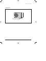
2. Product Specifications
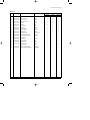
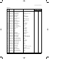
2-1 Table
MODEL
INDOOR UNIT
GH052EAM
GH070EAM
OUTDOOR UNIT
UH052EAMT
UH070EAMT
PG103M, PG103M1, PG103M2
PANEL
Cooling
Capacity
Heating
BTU/hr
18,700
23,900
Watts
5,500
7,000
BTU/hr
20,400
26,300
Watts
6,000
7,700
Power Supply
Power Input
Running Current
Fan Speed
Air Circulation
Indoor Unit
Noise Level
(Sound Pressure)
Heat Exchanger
Fan
Dimension
(Net / Gross)
Weight
Fan Speed
1ø, 220~240V~, 50Hz
1ø, 220~240V~, 50Hz
Cooling
Watts
1,750
2,350
Heating
Watts
1,800
2,500
Cooling
A
7.7
10.5
Heating
A
8.0
11.0
U-High
r.p.m
-
-
High
r.p.m
1,315
1,350
Mid
r.p.m
1,210
1,245
Low
r.p.m
1,105
1,140
High
m3 / min
14
14
Mid
m3 / min
12
12
Low
m / min
10
10.5
High
dB(A)
45
46
Mid
dB(A)
44
45
Low
dB(A)
43
44
Type
Slit-fin coil
Slit-fin coil
Row x Stages x Fin Pitch
2 x 10 x 1.3(580mm)
3 x 10 x 1.5(580mm)
Type
Cross Flow Fan
Cross Flow Fan
3
Motor Output
W
28
28
H
mm
230 / 299
230 / 299
W
mm
890 / 1,077
890 / 1,077
D
mm
575 / 642
575 / 642
Net / Gross
kg
21 / 25
22 / 26
High
r.p.m
750
850
Low
r.p.m
400
340
dB(A)
61
61
Propeller Fan
Propeller Fan
Sound Pressure Level
Fan
Type
Motor Output
W
Type
Outdoor Unit
Compressor
Heat Exchanger
Model
Motor Output
73
Rotary
Rotary
NN21VBAMT
NN29VACMT
1.3
1.9
Protection
Internal
Internal
Type
Slit-fin coil
Slit-fin coil
Row x Stages x Fin Pitch
2 x 28 x 1.5
2 x 28 x 1.5
Control
EEV
EEV
Type
R410A
R410A
1,550
1,650
Refrigerant
Charge
2
kW
60
g
Samsung Electronics
DB98_16890A(2)_1
5/10/04 2:09 PM
Page 3
Table(cont.)
MODEL
INDOOR UNIT
GH052EAM
GH070EAM
OUTDOOR UNIT
UH052EAMT
UH070EAMT
PANEL
Outdoor Unit
Dimension
(Net / Gross)
Weight
Indoor Unit
Condition
Outdoor Unit
Pipe O.D. Size
Piping
H
mm
648 / 749
648 / 749
W
mm
880 / 1,079
880 / 1,079
D
mm
310 / 418
310 / 418
Net / Gross
kg
67 / 72
69 / 74
Cool(DB/WB)
˚C
27 / 19
27 / 19
Heat(DB/WB)
˚C
20 / 15
20 / 15
Cool(DB/WB)
˚C
35 / 24
35 / 24
Heat(DB/WB)
˚C
7/6
7/6
Liquid
mm(inch)
6.35(1/4")
6.35(1/4")
Gas
mm(inch)
12.7(1/2")
15.88(5/8")
Connection Method
Between
Panel
PG103M, PG103M1, PG103M2
Dimension
(Net / Gross)
Weight
Flare
Flare
m
Max. 15
Max. 15
Pipe Length
m
Max. 30
H
mm
70 / 151
W
mm
1,030 / 1,103
D
mm
650 / 727
Net / Gross
kg
4/8
Height
Max. 30
Notice : Air Flow rate : Fan Step Control : Low → Mid → High
Samsung Electronics
3
DB98_16890A(2)_1
5/10/04 2:09 PM
Page 4
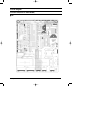
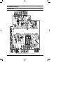
3. Operation Instruction & Installation
3-1 View of the Unit
3-1-1 Indoor Unit
(Unit : mm)
575
890
230
1,030
650
Filter Sign indicator
Fan indicator
Timer indicator
On/Off indicator
On/Off button
Remote control sensor
4
Samsung Electronics
DB98_16890A(2)_1
5/10/04 2:09 PM
Page 5
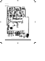
Operation Instruction & Installation
3-1-2 Outdoor Unit
648
(Unit : mm)
660
31
0
880
Samsung Electronics
5
DB98_16890A(2)_1
5/10/04 2:09 PM
Page 6
3-2 Air Conditioner and Accessories
The following accessories are supplied with the air conditioner.
■ The quantities are indicated in parentheses.
3-2-1 Accessories in the Indoor Unit Case
Pattern sheet
Insulation refrigerant
pipe
Insulation cover
drain
Flexible hose
Insulation drain
Installation manual
TIONS
OWNER’S INSTRUC
Splut-type Room
Rubber
Air Conditioner
Insulation cover
band
✳The following accessories are supplied with the indoor unit.
✳The type and quantity may differ depending on the specifications.
3-2-2 Accessories in the Outdoor Unit Case
Drain Plug (1)
Rubber LEG (4)
Nut(2)
3-2-3 Optional Accessories
■ Wired Remote Controller Accessories
Wired remote
controller(1)
Cable-tie(2)
Cable clamp(6)
M4x16 tapped
screw(7)
Indoor unit power
drawing cable(1)
Owner’s instructions(1)
Installation manual(1)
6
Samsung Electronics
DB98_16890A(2)_1
5/10/04 2:09 PM
Page 7
Operation Instruction & Installation
■ Wireless Remote Controller Accessories
Wireless
remote controller(1)
Battery(2)
Remote
control holder(1)
STS 2S-2x10 tapped
screw(2)
Owner’s instructions(1)
Installation manual(1)
Cable clamp(5)
M4x16 tapped screw(7)
Owner’s instructions(1)
Installation manual(1)
Cable clamp(6)
M4x16 tapped screw(7)
Owner’s instructions(1)
Installation manual(1)
Transmitter
communication cable(1)
Installation manual(1)
■ Centralized Controller Accessories
Centralized
controller(1)
Cable-tie(2)
■ Function Controller Accessories
Function
controller(1)
Cable-tie(2)
■ Transmitter Accessories
Transmitter(1)
Samsung Electronics
Transmitter power
cable(1)
7
DB98_16890A(2)_1
5/10/04 2:09 PM
Page 8
3-3 Installation
3-3-1 Before Installation
Keep the air conditioner drain hose outlet and inlet free from its surroundings.
In case of breakdown, keep the symmetry and fix it to prevent vibration.
The pipe length shall meet the standard as far as possible.
3-3-2 Installation Procedure
■ Location
Install the product in an area to guarantee the best cooling effect, convenience of piping and electric work, and inexistence of
vibration or wind in the vicinity.
■ Wall Drilling
Drill the wall downward in a diameter of 60 to 65mm.
■ Fixing Indoor Unit & Outdoor Unit
Fix the air conditioner hard enough so that it can not fall to the ground. On the roadside, the outdoor unit shall be installed 2m
above ground and kept away from pedestrians to prevent direct exposure to hot wind.
■ Pipe Spooling & Connecting
You shall cut the pipe straightly with a pipe cutter and grind all the burrs of the cut surface.
Pipe expansion may continue until the pipe surface becomes uneven or torn apart.
Be sure to use a torque wrench to tighten pipes or flare nuts.
<Torque & Depth>
Outer Diameter(D)
Torque(kgf.cm)
Depth(A)
6.35mm(1/4")
140~170
1.3mm
9.52mm(3/8")
250~280
1.8mm
12.70mm(1/2")
380~420
2.0mm
15.88mm(5/8")
440~480
2.2mm
19.05mm(3/4")
990~1,210
2.2mm
D
A
■ Leak Test
Put an inert gas like nitrogen in the outdoor unit pipe and put soap bubbles or other test liquids on he pipe surface for the leak test.
■ Drain Hose Connecting
Install the drain hose downward to drain water naturally. Be sure to pour water into the hose to check if it drains well.
■ Electric & Earth Work
Electric and earth work shall meet the "Electric Facility Technology Standard" and the "Internal Wire Regulation" of the Electric
Business Laws.
■ Inspection & Trial Run
Upon completion of the tests, you shall make a trial run while you explain the main functions of the air conditioner to finish the
installation.
8
Samsung Electronics
DB98_16890A(2)_1
5/10/04 2:09 PM
Page 9
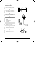
3-4 Installation Diagram of Indoor Unit and Outdoor Unit
3-4-1 Air-Purge Procedure
1) Connect each assembly pipe to the appropriate
valve on the outdoor unit and tighten the flare nut.
Indoor unit
Outdoor unit
A
Gas pipe side
C
B
Liquid pipe side
D
2) Connect the charging hose of low pressure side
of manifold gauge to the packed valve having a
service port (3/8" Packed valve) as shown at the
figure.
3) Open the valve of the low pressure side of
manifold gauge counter-clockwise.
4) Purge the air from the system using vacuum
pump for about 30 minutes.
- After that, please recheck that pressure is
stabilization.
- Close the valve of the low pressure side of
manifold gauge clockwise.
- Remove the hose of the low pressure side
of manifold gauge.
5) Set valve cork of both liquid side and gas side of
packed valve to the open position.
Vacuum Pump
6) Mount the valve stem nuts to the 2-Way and
3-Way valve. And mount the service port cap to
3-Way valve.
B
(liquid)
A
(gas)
7) Check for gas leakage.
- At this time, especially check for gas
leakage from the 3-Way valve’s stem nuts,
and from the service port cap.
Stem cap
Valve stem
Samsung Electronics
9
DB98_16890A(2)_1
5/10/04 2:09 PM
Page 10
Operation Instruction & Installation
3-4-2 Refrigerant Refill
Refill an air conditioner with refrigerant when refrigerant has been leaked at installing or using.
1) Purge air(for new installation only).
2) Turn the 3-Way valve clockwise to close,
connect the pressure gauge (low pressure side)
to the service valve, and open the 3-Way valve
again.
Suspension hook
Compound
gauge
High
pressure
gauge
Hand
wheel
3) Connect the tank to refill with refrigerant.
4) Set the unit to cool operation mode.
Finger tight
fittings
For mounting
other and of
hose when
not in use
Connected to
high pressure
side
Charging line
5) Check the pressure indicated by the pressure
gauge(low pressure side).
* Standard pressure is should be 14~16kg/cm2
in a regular, high operation mode.
6) Open the refrigerant tank and fill with refrigerant
until the rated pressure is reached.
* It is recommended not to pour the refrigerant
in too quickly, but gradually while operating a
pressure valve.
7) Stop operation of the air conditioner.
8) Close the 3-Way valve, disconnect the
pressure gauge, and open the 3-Way valve
again.
9) Close the cap of each valve.
10
Samsung Electronics
DB98_16890A(2)_1
5/10/04 2:09 PM
Page 11
Operation Instruction & Installation
3-4-3 ”Pump down” Procedure
Pump down will be carried out when an evaporator is replaced or when the unit is relocated in another area.
1) Remove the caps from the 2-Way valve and the
3-Way valve.
2) Turn the 3-Way valve clockwise to close and
connect a pressure gauge (low pressure side)
to the service valve, and open the 3-Way valve
again.
3-Way Valve
3) Set the unit to cool operation mode.
(Check if the compressor is operating.)
2-Way Valve
4) Turn the 2-Way valve clockwise to close.
5) When the pressure gauge indicates "0" turn the
3-Way valve clockwise to close.
6) Stop operation of the air conditioner.
7) Close the cap of each valve.
Relocation of the air conditioner
• Refer to this procedure when the unit is relocated.
• Carry out the pump down procedure (refer to the details of 'pump down').
• Remove the power cord.
• Disconnect the assembly cable from the indoor and outdoor units.
• Remove the flare nut connecting the indoor unit and the pipe.
• At this time, cover the pipe of the indoor unit and the other pipe using a cap or vinyl plug to avoid foreign
material entering.
• Disconnect the pipe connected to the outdoor unit.
At this time, cover the valve of the outdoor unit and the other pipe using a cap or vinyl plug to avoid foreign
material entering.
• Make sure you do not bend the connection pipes in the middle and store together with the cables.
• Move the indoor and outdoor units to a new location.
• Remove the mounting plate for the indoor unit and move it to a new location.
Samsung Electronics
11
DB98_16890A(2)_1
5/10/04 2:09 PM
Page 12
3-5 Installation
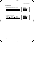
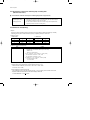
3-5-1 Assigning Address to Indoor Unit
1. Before installing the indoor unit, assign an address to the indoor unit according to the air conditioning system plan.
2. The address of the indoor unit is assigned by adjusting MAIN(SW02) and RMC(SW01) rotary switches.
SW02 MAIN
SW03
SW04
SW01 RMC
SW05
K5 K6 K7 K8
K1 K2 K3 K4
K9 K10 K11 K12
✳ Yon don’t have to assign the MAIN address when installing an indoor unit for one outdoor unit.
3. The MAIN address is for communication between the indoor unit and the outdoor unit.
Therefore, you must set it to operate the air conditioner properly.
4. It is required to set the RMC address if you install the wired remote controller and/or the centralized controller.
5. If you install optional accessories such as the wired remote controller, centralized controller, etc. see an appropriate
installation manual.
6. If an optional accessory is not installed, you do not have to set the RMC address. However, adjust K1 and K2 switches of
the SW03 DIP switch to "ON" position in this case.
7. Set the MAIN address by adjusting the rotary switch(SW02) from 0 to F. Each indoor unit connected to the same outdoor
unit must have different address.
7. i. e. If an indoor unit does not have an optional accessory and
its MAIN address is "0".
SW04
SW02 MAIN
SW01 RMC
SW03
SW05
K5 K6 K7 K8
K1 K2 K3 K4
12
K9 K10 K11 K12
Samsung Electronics
DB98_16890A(2)_1
5/10/04 2:09 PM
Page 13
Operation Instruction & Installation
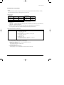
3-5-2 Additional Functions
■ Compensation for lost temp. in heating operation
■ • Reduces the difference between an actual room temp. and a sensed
■ • temp. by the air conditioner when heating.
K5 K6 K7 K8
SW04
Switch No.
Switch ON
Switch OFF
K5
2°C compensation
5°C compensation
■ Adjusting filter cleaning cycle
■ • You can adjust the cycle for filter sign indicator.
K5 K6 K7 K8
Switch No.
Switch ON
Switch OFF
K6
1000 hours
2000 hours
Samsung Electronics
SW04
13
DB98_16890A(2)_1
5/10/04 2:09 PM
Page 14
Operation Instruction & Installation
3-5-3 Setting Up Option Switches
■ Option Switch
Rotary Switch
Display
Key
■ Rotary Switch
■ You should display that how many indoor units are connected to the
outdoor unit. Refer to the table below, then turn the arrow to appropriate
position.
Switch No.
Number of
indoor unit(s)
Switch No.
Number of
indoor unit(s)
0 or 1
One
9
Nine
2
Two
A
Ten
3
Three
B
Eleven
4
Four
C
Twelve
5
Five
D
Thirteen
6
Six
E
Fourteen
7
Seven
F
Fifteen
8
Eight
-
-
■ KEY
■ Display
DIS 1
K1
K2
CHECK MODE
14
K3
RESET
DIS 2
K4
DISPLAY
MODE
SEG 1
SEG 2
SEG 3
SEG 4
Samsung Electronics
DB98_16890A(2)_1
5/10/04 2:09 PM
Page 15
Operation Instruction & Installation
■ Summary of KEY functions
Function
K1
Number
(Displayed
on SEG 3, 4)
of press times
K2
(Displayed on SEG 3, 4)
K3
(Displayed on SEG 3, 4)
K4
(Displayed on SEG 3, 4)
1
Adding refrigerant at
heating mode
Adding refrigerant at
cooling mode
Reset
Displays data
2
Test operation at
heating mode
Test operation at
cooling mode
-
-
3
End
Pump Down for recovery
of refrigerant
-
-
4
-
End
-
-
✳ Use the K1 only for heat pump models.
■ Reading data indicated on the display
KEY
K1
Example
Number of
press
Item
Display
1
Adding refrigerant for heat pump models
2
Test operation for heat pump models
3
End
1
Adding refrigerant for cooling only models
2
Test operation for cooling only models
3
Pump Down for recovery of refrigerant
4
End
Meaning
K2
K3
K4
Reset
110 °C
1
Discharge temp. of compressor
2
Temp. of outdoor heat exchanger
38 °C
3
Outdoor temp.
34 °C
4
Step of electronic expansion valve
(0 step : all closed, 480 step : all open)
5
Temp. of evaporator
6
Indoor temp.
7
Stopping view mode & display communication data
Samsung Electronics
120STEP
(12 x 10)
-2 °C
12 °C
22 °C
15
DB98_16890A(2)_1
5/10/04 2:20 PM
Page 16
4. Disassembly and Reassembly
Stop operation of the air conditioner and remove the power cord before repairing the unit.
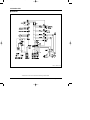
4-1 Indoor Unit
No
Parts
1
Front Grille
_ Dust-Collecting
Procedure
Remark
1) Press the "PUSH".
Filter
2) Front Grille Disassembly
(1) Open the Front Grille and pull it up to
the direction in the picture.
(2) Detach the Safe Ring.
3) Filter Disassembly
(1) Detach the Filter by disassembling the
Grille hook.
16
Samsung Electronics
DB98_16890A(2)_1
5/10/04 2:09 PM
Page 17
Disassembly and Reassembly
No
Parts
Procedure
Remark
4) Detach 6 bolts and 2 fixing screws
connected to the Main Body.(Mark point)
5) Unscrew a mark point in the picture,
and detach the Cover from the Panel
with pushing the hook.
6) Detach the connection wires of Step
Motor and the receive part from the wire
of a Main Body.
7) Widen the both hooks of panel hooked
with the Main Body to both sides, and
detach the Panel from the Indoor Unit.
Samsung Electronics
17
DB98_16890A(2)_1
5/10/04 2:09 PM
Page 18
Disassembly and Reassembly
No
Parts
2
Electronic Part
_Indoor & Outdoor
Connecting Cable
Procedure
Remark
1) Unscrew 2 fixing screws of the Case
control and screw of Thermistor wire and
holder.
2) Push the hook, and pull the knob of a
case.
3) Detach the indoor and outdoor connection
wire cable connected to the Terminal.
4) Detach the Fan Motor connection wire,
Heat Exchanger Sensor connection wire,
and the Drain Pump Float S/W connection
wire from the connecter.
5) Detach the Control Box from the main body.
18
Samsung Electronics
DB98_16890A(2)_1
5/10/04 2:09 PM
Page 19
Disassembly and Reassembly
No
Parts
3
EVAP ASS'Y
Procedure
Remark
1) Unsrew 3 screws connected to the main
body and Cover Side.
2) Detach the Cover Side if from the main
body.
3) Unscrew 16 screws connected to the Drain
Pan and the main body.(Mark point)
4) Detach the Drain Pan from the main body.
5) Unscrew 4 Heat Exchanger screws
connected to the cabinet body and cover
Evap Guide.
Samsung Electronics
19
DB98_16890A(2)_1
5/10/04 2:09 PM
Page 20
Disassembly and Reassembly
No
Parts
Procedure
Remark
6) Detach the Drain Pump Sensor from the
holder, and detach the Heat Exchanger
from the main body by pushing it to the
direction of Drain.
4
Fan
&
Motor
1) Unscrew 4 screws of Cover Motor and
Evap Guide connected to the Case Motor.
2) After detaching the Cover Motor by
pushing the hook, detach the Cover Evap
Guide.
3) Detach the Motor and Fan from the case.
(Use M3 wrench when detaching the Motor
from the Fan.)
20
Samsung Electronics
DB98_16890A(2)_1
5/10/04 2:09 PM
Page 21
Disassembly and Reassembly
No
Parts
5
Drain Pump
Procedure
Remark
1) Detach the Drain Hose connected to the
Drain Pump by loosening the spring.
2) Unscrew 4 screws connected to the
Holder Pump and Drain Pump.
3) After connector detaching, detach the Drain
Pump from the holder.
6
Other Parts
Samsung Electronics
1) In case of the other parts, detach it like a
picture when necessary.
21
DB98_16890A(2)_1
5/10/04 2:09 PM
Page 22
Disassembly and Reassembly
No
Parts
7
Front Panel
Procedure
Remark
1) Unscrew 2 screws of the Holder Motor
fixed on the Panel, and detach the Holder
Motor. The Panel, and detach the Holder
Motor.
2) Unscrew 2 screws of the Step-Motor,
and detach the Step-Motor from the Panel.
3) Detach the cable clamp screw.
4) Push the hook of case PCB to the both
sides and detach the case from the Panel.
22
Samsung Electronics
DB98_16890A(2)_1
5/10/04 2:09 PM
Page 23
Disassembly and Reassembly
No
Parts
Procedure
Remark
5) When detaching the PCB from the case,
unscrew the 6 screws and push the hook
at the mark.
6) When detaching the blade, detach the
opposite side first of Step Motor after
turning over the guide on the Panel.
7) When detaching the Blade V, after
detaching the link by pushing, detach
the blade with pushing to the direction
of arrow.
Samsung Electronics
23
DB98_16890A(2)_1
5/10/04 2:09 PM
Page 24
4-2 Outdoor Unit
No
Parts
1
Common Work
Procedure
Remark
1) Loosen the fixing screws and separate the
Cover Control.
2) Separate the connection wire from the
Terminal Block.
3) Loosen the fixing screws and separate the
Upper Cabinet.
4) Loosen the fixing screws and separate the
Front Cabinet.
5) Loosen 2 screws and pull up the
Control Box.
6) Separate the terminal cover and separate
the Comp lead wire.
24
Samsung Electronics
DB98_16890A(2)_1
5/10/04 2:09 PM
Page 25
Disassembly and Reassembly
No
Parts
Procedure
Remark
7) Loosen the fixing screws and separate the
Cabinet Side.
2
Fan
&
Motor
1) Loosen the fixing bolt and separate
the Fan.
2) Loosen 4 fixing bolts to separate
the Motor.
Samsung Electronics
25
DB98_16890A(2)_1
5/10/04 2:09 PM
Page 26
Disassembly and Reassembly
No
Parts
3
Heat Exchanger
&
Compressor
26
Procedure
Remark
1) Release the refrigerant at first.
2) Disassemble the inlet and outlet pipe
by welding.
3) Loosen the fixing screws of the Heat
Exchanger.
4) Separate the Heat Exchanger.
5) Loosen four bolts of the Compressor.
6) Separate the Compressor.
Samsung Electronics
DB98_16890A(2)_1
5/10/04 2:09 PM
Page 27
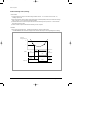
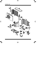
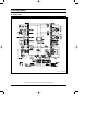
5. Refrigerating Cycle Diagram
INDOOR UNIT
OUTDOOR UNIT
*Allowable pipe length : Max. 50m
*Allowable drop distance : Max. 30m
EEV
3-Way Valve
Liquid Side
Filter
Filter
Heat
Exchanger
(Condensor)
Heat
Exchanger
(Evaporator)
Gas Side
3-Way Valve
Cooling
Heating
Gas leak check point
Samsung Electronics
Muffler
Accumulator
Compressor
27
DB98_16890A(2)_1
5/10/04 2:09 PM
Page 28
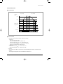
5-2 Refrigerant Cycle Characteristic
5-2-1 Capacity Distributions
Capacity Distributions according to indoor and outdoor temp. variation.
■ COOLING MODE
■ GH052EAM
105
102.46
99.09
100
97.98
93.17
Capacity (%)
95
90
91.46
83.93
85
7.5m
80
30m
75
70
5
10
15
20
25
30
35
40
45
Outdoor Temperature (ßC)
■ GH070EAM
105
98.12
100
102.31
99.3
99.9
95
Capacity (%)
96.21
90
87.83
85
79.03
80
75
76.69
7.5m
70
30m
65
60
5
10
15
20
25
30
35
40
45
Outdoor Temperature (ßC)
28
Samsung Electronics
DB98_16890A(2)_1
5/10/04 2:09 PM
Page 29
Refrigerating Cycle Diagram
■ HEATING MODE
■ GH052EAM
110
100
Capacity (%)
100
90
94.66
80.72
80
80.19
68.76
70
7.5m
65.25
60
59.58
30m
55.23
50
-15
-10
-5
0
5
10
15
20
25
30
Outdoor Temperature (ßC)
■ GH070EAM
110
104.44
99.12
100
104.12
Capacity (%)
90
92.79
80
74.07
70
63.88
7.5m
60
63
57.3
30m
50
-15
-10
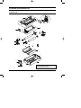
-5
0
5
10
15
20
25
30
Outdoor Temperature (ßC)
Samsung Electronics
29
DB98_16890A(2)_1
5/10/04 2:09 PM
Page 30
Refrigerating Cycle Diagram
5-2-2 Power Consumption Distributions
Power Consumption Distributions according to indoor and outdoor temp. variation.
■ COOLING MODE
■ GH052EAM
120
109
110
Consumption (%)
100.84
111.41
100
98.74
90
84.06
80
82.72
7.5m
70
30m
60
5
10
15
20
25
30
35
40
45
Outdoor Temperature (ßC)
■ GH070EAM
130
121.5
120
Consumption (%)
118.7
106.4
110
100
103.1
92.72
92.1
90
92.94
80
7.5m
70
30m
60
5
10
15
20
25
30
35
40
45
Outdoor Temperature (ßC)
30
Samsung Electronics
DB98_16890A(2)_1
5/10/04 2:09 PM
Page 31
Refrigerating Cycle Diagram
■ HEATING MODE
■ GH052EAM
120
Consumption (%)
110
106.25
100.71
106.12
100
99.65
88.99
90
83.6
80
89.99
7.5m
82.98
30m
70
-15
-10
-5
0
5
10
15
20
25
30
Outdoor Temperature (ßC)
■ GH070EAM
110
102.16
100.43
Consumption (%)
100
100.13
96.44
90
83.26
78.83
80
81.57
77.77
7.5m
70
30m
60
-15
-10
-5
0
5
10
15
20
25
30
Outdoor Temperature (ßC)
Samsung Electronics
31
DB98_16890A(2)_1
5/10/04 2:09 PM
Page 32
Refrigerating Cycle Diagram
5-2-3 Low Pressure Distributions
■ COOLING MODE
■ GH052EAM
Low Pressure (kg/cm2G)
12
9.88
10
8.42
7.51
8
8.47
8.27
7.08
6
7.5m
4
30m
2
5
10
15
20
25
30
35
40
45
Outdoor Temperature (ßC)
■ GH070EAM
Low Pressure (kg/cm2G)
12
9.31
10
8.02
7.84
8
8.7
7.76
6.3
6
5.78
7.5m
4
30m
2
5
10
15
20
25
30
35
40
45
Outdoor Temperature (ßC)
32
Samsung Electronics
DB98_16890A(2)_1
5/10/04 2:09 PM
Page 33
Refrigerating Cycle Diagram
5-2-4 High Pressure Distributions
■ HEATING MODE
■ GH052EAM
40
High Pressure (kg/cm2G)
34.47
35
34.02
28.65
30
25.32
25
22.82
20
22.18
28.27
24.53
7.5m
30m
15
-15
-10
-5
0
5
10
15
20
25
30
Outdoor Temperature (ßC)
■ GH070EAM
High Pressure (kg/cm2G)
40
34.19
35
34.55
30.18
30
29.52
25.04
25
7.5m
23.83
30m
23.56
22.23
20
-15
-10
-5
0
5
10
15
20
25
30
Outdoor Temperature (ßC)
Samsung Electronics
33
DB98_16890A(2)_1
5/10/04 2:09 PM
Page 34
Refrigerating Cycle Diagram
5-2-5 Air Volume according to the RPM variation(High/Mid/Low)
■ Indoor Unit
m3/min 15
14.5
14
13.5
13
12.5
12
11.5
11
10.5
10
9.5
9
8.5
8
7.5
7
High
Mid
Low
GH052EAM-Cooling-Vol.
GH052EAM-Heating-Vol.
GH070EAM-Cooling-Vol.
GH070EAM-Heating-Vol.
RPM
■ Outdoor Unit
- UH052EAMT : 45m3 / min
- UH070EAMT : 51m3 / min
34
Samsung Electronics
DB98_16890A(2)_1
5/10/04 2:09 PM
Page 35
Refrigerating Cycle Diagram
5-2-6 Noise Level according to the RPM variation(High/Mid/Low)
■ Indoor Unit
dB 46
45
44
43
42
41
40
39
38
37
High
Mid
Low
GH052EAM-Cooling-Noise
GH052EAM-Heating-Noise
GH070EAM-Cooling-Noise
GH070EAM-Heating-Noise
RPM
■ Outdoor Unit
Section
UH052EAMT
UH070EAMT
Samsung Electronics
Operation
Noise(dB)
Cooling
61
Heating
61
Cooling
61
Heating
61
Remark
35
DB98_16890A(2)_1
5/10/04 2:09 PM
Page 36
5-3 Cautions Of using for R410A
■ HFCs
1. When installing or removing or servicing an air conditioner, do not allow air or moisture to remain in the refrigeration cycle.
2. When evacuating an air conditioner, always use the vacuum pump and sufficiently evacuate an air conditioner.
3. Certainly use the specified lubricant(Polyol ester oil), valve and dryer.
■ Lubricants
1. Synthetic Oils : POE, PVE, PAG, AB
2. POE is made from Acid and Alcohol
1. RCOOH(Carboxylic Acid) + R'OH(Alcohol) ↔ RCOOR'(Ester) + H2O(Water)
3. Hydrolysis causes Metallic Soap
1. RCOOR' + H2O → RCOOH + R'OH
1. FeO + 2RCOOH → Fe(COOR)2(Carboxylic Acid Iron(slurgy))
36
Samsung Electronics
DB98_16890A(2)_1
5/10/04 2:09 PM
Page 37
6. Feature & Operation
6-1 The Feature of Key in remote control
No
BUTTON
FUNCTION
On/Off & Timer Set/Cancel button.
Press the
button to stop and run the air conditioner or set up On/Off timer.
1
Mode selection button.
Each time you press this button,
mode is changed in the following order.
: Auto Mode
: Fan Mode
: Cool Mode
: Heat Mode
√ In case of Heat pump model
: Dry Mode
2
√ In case of Cooling only model
(UP)
Temp. adjustment button(UP).
The temperature is increase by the pressing the temp. button.
(DOWN)
Temp. adjustment button(DOWN).
The temperature is decrease by the pressing the temp. button.
3
4
5
Filter Reset button.
When the filter lamp is on the indoor DISPLAY part, replace the filter and press the reset button.
Fan speed adjustment button.
Each time you press this button,
FAN SPEED is changed in the following order.
6
Swing button.
It adjusts the airflow to upward and downward.
7
On Timer button.
The On Timer enables you to switch on the air conditioner automatically after a given period
of time that is from 30 minutes to 24 hours.
To cancel, press the
(Set/Cancel) button.
8
Off Timer button.
The Off Timer enables you to switch off the air conditioner automatically after a given period
of time that is from 30 minutes to 24 hours.
To cancel, press the
(Set/Cancel) button.
Samsung Electronics
37
DB98_16890A(2)_1
5/10/04 2:09 PM
Page 38
6-2 Details for Operation Property
6-2-1 Automatic control
● Automatic operation mode
✳ Ts=Remote Setting Temp.
Room Temp.(˚C)
Cooling operation Ts = 18˚C ~ 30˚C
Ts -1˚C
Heating operation Ts = 16˚C ~ 30˚C
1. First selection of auto control at the other operation mode.
1. When auto operation on from off state
1. To determine the initial operation mode by comparing the room temp. and desired temp. (Ts)
1. - Room Temp. (Tr) ≥ Desired temp.(Ts) - 1˚C : cooling mode
1. - Room Temp. (Tr) < Desired temp.(Ts) - 1˚C : heating mode
2. Wind velocity control
1. - Auto cooling operation : auto operation for wind velocity of cooling
1. - Auto heating operation : auto operation for wind velocity of heating
3. Default temp. after RESET
3. → Setting temp. = 24˚C(18˚C ~ 30˚C able to set)
3. → Air flow setting = Auto
● To re-determine the operation mode (AUTO-CHANGE-OVER)
1. In case of cooling mode of the operation mode set at the initial auto operation.
When operating with Room temp.(Tr) ≤ Setting temp.(Ts) - 1˚C for more than 30 minutes, reset the operation mode.
2. In case of heating mode of operation set at the initial auto operation.
When operating with Room temp. (Tr) ≥ Setting temp.(Ts) + 1 + ∆ T ˚C for more than 30 minutes, reset the operation mode.
2. (∆T = offset temp. of heating by option(switch No. K5) 2˚C / 5˚C)
38
Samsung Electronics
DB98_16890A(2)_1
5/10/04 2:09 PM
Page 39
Feature & Operation
6-2-2 Cooling operation control
● Operation Pattern
1. COMPor ON/OFF control
✳ Ts=Remote Setting Temp.
Room Temp.(°C)
Ts
Ts-1
COMPor
Control
ON
OFF
ON
● Operation specification
1. Control of Setting temp.
1. → remote control setting : 18˚C ~ 30˚C
2. COMPor ON/OFF control
1. → Compressor turn on/off control according to the setting temp. and room temp.
1. → COMPor off : "Room temp. ≤ setting temp.(Ts)-1"
1. → COMPor on : "Room temp. ≥ setting temp.(Ts)"
3. Air flow control
1. → Operation by the wind velocity set at the remote control
4. Air flow direction control
1. 1) A Initial air flow direction when resetting the power source
1. 1) → An internal angle 30˚ position
5. Initial setting value
1. → Setting temp.(Ts) = 24[˚C]
1. 1) Air flow set = Air flow auto
6. Control according to indoor heat exchanger temp.
1. → Protection by Anti-freezing control (low temp. release)
7. THERMO ON/OFF Delay control
1. When Indoor unit THERMO ON → OFF, 20 seconds delay of THERMO OFF. (including in operation ON/OFF)
8. THERMO OFF control
1. - When comp off by the room temp. thermo off.
1. - Indoor fan speed → low, louver angle → minimum control
Samsung Electronics
39
DB98_16890A(2)_1
5/10/04 2:09 PM
Page 40
Feature & Operation
6-2-3 Dehumidifier control
● Operation Pattern
✳ Ts=Remote Setting Temp.
Room Temp.(°C)
(I-MODE)
Ts+4
(II-MODE)
Ts+3
Ts+2
(III-MODE)
Ts+1
Ts
(IV-MODE)
Ts-1
● Operation spec
1. On/Off time as per dehumidifying mode and operation cycle indoor
Operation Cycle(Min.)
COMPor &
Indoor Fan
I-Mode
II-Mode
III-Mode
ON Time
6 Min.
5 Min.
3 Min.
OFF Time
4 Min.
5 Min.
6 Min.
IV-Mode
COMPOR=OFF
2. COMPor and indoor fan operation fan cycle
Room Temp.(°C)
COMPor
operation
ON
OFF
ON
OFF
ON
Indoor
fan operation
OFF
low
initial
set
3 min
1st CYCLE
2nd CYCLE
3 min
3 min
♦ To determine the other
dehumidifying 3 minutes
after COMPor ON
1. 1) Check the room temp. 3 minutes after compressor On every cycle to determine the next cycle.
1. 1) → To determine the other cycle by monitoring the room temp. continuously at "IV-MODE"
1. 2) The 6 minutes delay (including 3 minutes delay ) after dehumidifying operation set shall be operated by compressor on,
indoor fan = low.
1. 3) Operation by compressor = on/off (mode I, II, III, IV) from the dehumidifying "1st CYCLE"
indoor fan = low
3. Air flow direction control → according to the set of remote control
4. Default temp. after Reset(Ts) : 24˚C
40
Samsung Electronics
DB98_16890A(2)_1
5/10/04 2:09 PM
Page 41
Feature & Operation
6-2-4 Fan operation mode control
● Operation Pattern
1. COMPor and outdoor fan control
COMPor
Control
ON
outdoor fan
control
ON
OFF
↑
set
Fan control
2. Indoor fan control
Remote control display
Indoor fan mode
natural wind
natural wind
High
Mid
Low
● Operation specification
● 1. When receiving the signal of Fan control from Remote control.
● 1. → Outdoor power RELAY OFF (COMPor OFF, outdoor fan OFF), indoor fan operating by the setting Fan mode.
● 1. → "low → mid → high → natural wind" to be changed in order.
● 2. Set Fan mode by low when resetting the initial reset.
●
●
●
●
●
3. Air flow direction control (left and right) (upper and lower)
1. 1) Initial air flow direction during power reset
1. 1) → An internal angle 33.88˚ position, left and right louver SWING OFF
1. 2) Upper / lower louver : upper / lower control referred
1. 3) Left/right louver : left/right louver control referred
Samsung Electronics
41
DB98_16890A(2)_1
5/10/04 2:09 PM
Page 42
Feature & Operation
6-2-5 Heating operation control
● Operation Pattern
✳ Ts=Setting Temp.
∆ T=temp. by the cooling operation
option(2˚C/5˚C)
Indoor Temp.(°C)
Ts+1+∆T
Ts-1+∆T
COMPor
Control
ON
OFF
ON
● Operation specification
1. COMPor ON/OFF Control
1. Control of compressor on/off by the indoor temp. and setting temp.
1. 1) Compressor on/off control by the room temp.
1. 1) → Compressor Off at "room temp. = desired temp.(Ts)+1+∆T"
1. 1) → Compressor On at indoor temp. = desired temp.(Ts)-1+∆T".
1. 2) Compressor control according to the indoor heat exchanger temp.
1. 1) → Following the high load prevention control (high temp. release).
1. 1) → Having the priority over Compressor by the indoor temp.
2. Air flow control
1. 1) Fan control by the room temp.
1. 1) → Air flow control by the remote control.
1. 2) Fan speed control by the indoor heat exchanger
1. 1) → According to the cool air prevention control and high load prevention control (high temp. release)
1. 1) → To have the priority over the wind velocity control by the room temp.
3. Air direction control
1. → according to the set of remote control.
4. Initial after reset
4. → Setting temp.(Ts) = 24[˚C]
4. → Air flow setting = auto
5. THERMO ON/OFF delay control
5. Two minutes delay of thermo off when indoor unit THERMO ON → OFF(including operation on/off)
6. THERMO OFF control
5. When compressor off due to the thermo off of set temp. and room temp.
5. Indoor fan → low, louver angle → minimum control
42
Samsung Electronics
DB98_16890A(2)_1
5/10/04 2:09 PM
Page 43
Feature & Operation
6-2-6 Cold draft control
● Operation Pattern
(temp. increase)
Indoor unit
sensor
(temp. decrease)
40˚C
34˚C
24˚C
Indoor fan mode
Setting fan mode
Low
Indoor OFF
COMP
OFF
ON
OFF
● Indoor fan control
1. To control the indoor fan according to the temp. of indoor heat exchanger
1. 1) COMPor ON
1. 1) - Temp. rise of indoor heat exchanger
1. 1) - indoor heat exchanger temp. < 34˚C → indoor fan : OFF
1. 1) - indoor heat exchanger temp. 34˚C ≤ 40˚C → indoor fan mode : Low
1. 1) - indoor heat exchanger temp. 40˚C → indoor fan mode : setting mode.
1. 1) - Adjust Fan mode automatically for controlling cold draft.
1. 2) COMPor OFF
1. 1) Indoor heat exchanger temp. 24˚C → indoor fan mode : Low
1. 1) Indoor heat exchanger temp. < 24˚C → indoor fan mode : OFF
2. Exceptions
2. If it is "Indoor fan ON + COMPor on", the indoor fan is not turn off automatically even if the temp. of evaporator decrease
under 24˚C.
2. ✳ Even during the comp off operation, the fan on is maintained if the condition is fan on.
Samsung Electronics
43
DB98_16890A(2)_1
5/10/04 2:09 PM
Page 44
Feature & Operation
6-2-7 The protection control by the condensing temp. on heating mode.
(The indoor unit sensor)
● Control method : Protection control by the condensing temp.(indoor unit pipe sensor)
protection control by the
condensing temp. during
heating (pipe sensor)
1. COMP DOWN
1) When the room pipe temp. is above 70˚C during heating, the comp shall be stopped
immediately and restart it 3 minutes and under 50 ˚C.
✳ In case of 2-WAY CASSETTE, there are two Indoor unit pipe sensors.(determind the
higher temp. between 2 sensors for heating mode.)
6-2-8 Outdoor fan control(Heating)
1. Purpose
1. The indoor fan shall be controlled according to the outdoor temp. during heating to maintain the exhaust temp. constantly
(condensing pressure) and to maintain the outdoor pipe temp. (evaporation pressure) at a certain level.
2. Outdoor fan control
•
•
2 FAN control
1 FAN control
MODE
UPPER FAN
LOWER FAN
MODE
FAN
2
H
H
2
H
1
L
L
1
L
0
Stop
Stop
0
Stop
3. Outdoor fan control as per outdoor temp.
Items
Outdoor fan control
Heating
1) Outdoor temp. > 30˚C : outdoor fan → STOP + (STOP)
1) (Applicable temp. is exceeded if outdoor temp. is above 30˚C)
1) - COMPor OFF.
1) - Indoor fan : cold draft control
2) 12˚C < outdoor fan ≤ 30˚C :outdoor fan → LOW + (LOW)
2) √ 2-FAN model : outdoor fan → LOW + LOW
2) √ 1-FAN model : outdoor FAN → LOW
3) Outdoor temp. ≤ 12˚C : outdoor fan → HIGH + (HIGH)
3) ✳ For two fans, HIGH + HIGH
3) ✳ For one fan HIGH
4. Fan control by the indoor pipe sensor (condensing temp.) in case of outdoor temp. > 12˚C
4. 1) detection method : when maintaining for 2 seconds with indoor pipe temp. ≥ 53˚C
4. 1) : Outdoor fan FAN 1 STEP down (ie, for two fans, LOW + LOW → STOP + STOP
4. 1) : For one fan, LOW → STOP)
4. 2) Control reset(restore to the previous fan step)
4. 1) : When maintaining for two seconds with Indoor fan pipe temp. ≤ 48˚C or exceeding 120 seconds with outdoor fan off,
4. 1) ✳ Operate the outdoor fan with minimum F seconds when restarting the outdoor fan.
F second OPTION time : 5, 10, 20, 30 seconds
44
Samsung Electronics
DB98_16890A(2)_1
5/10/04 2:09 PM
Page 45
Feature & Operation
6-2-9 Outdoor fan control(cooling)
1. Purpose
1. The outdoor fan shall be controlled according to the outdoor temp. during cooling to maintain the indoor exhaust temp. constantly
and to maintain the outdoor pipe temp. (condensing pressure) at a certain level.
2. Outdoor fan mode
•
•
2 FAN control
1 FAN control
MODE
UPPER FAN
LOWER FAN
MODE
FAN
3
H
H
2
H
2
L
L
1
L
1
L
Stop
0
Stop
0
Stop
Stop
2. ✳ Detection method of outdoor temp. when outdoor fan off (only for cooling operation)
2. ✳ 1) Outdoor fan off
2. ✳ 1) - COMPor ON
: Ignoring the outdoor temp. detection (prevention of mis-detection of the outdoor temp. by the radiated heat)
2. ✳ 1) - COMPor OFF : Detection of outdoor temp.
2. ✳ 2) Outdoor fan on : Ignore the outdoor temp. for 30 seconds after the fan on and afterwards detect the outdoor temp.
2. ✳ 2) - In case of ignoring the outdoor temp, it shall be acknowledged as the final temp. before the fan off.
3.Outdoor fan control method as per outdoor temp.
Items
Outdoor fan control
Cooling
1) Outdoor temp. > 30˚C : Outdoor fan → HIGH + (HIGH)
1) ✳ For two fans, HIGH + HIGH
1) ✳ For 1 FAN, HIGH
2) 20˚C < outdoor temp. ≤ 30˚C : Outdoor fan → LOW + (LOW)
1) ✳ For two fans, LOW + LOW
1) ✳ For one fan, LOW
3) Outdoor temp. ≤ 20˚C
1) √ 2-FAN model : Outdoor fan → LOW(upper ) + STOP(Lower)
1) √ 1-FAN model : Outdoor fan → LOW
3.◆ Outdoor fan ≤ 12˚C
3.◆ → Fan control by detecting the outdoor pipe temp. (condensing temp.)
3.◆ → 1) Detection method : outdoor pipe temp. ≤ 39˚C to be maintained for 10 seconds
3.◆ → 1) : Outdoor fan 1 STEP down
3.◆ → 1) : (ie, For two fans LOW + STOP → STOP + STOP
3.◆ → 1) : For one fan LOW → STOP)
3.◆ → 2) Control reset (Restore to the previous step )
3.◆ → 1) : Outdoor pipe temp. ≥ 46˚C to be mantained for two seconds or fan off for 60 seconds
Samsung Electronics
45
DB98_16890A(2)_1
5/10/04 2:09 PM
Page 46
Feature & Operation
6-2-10 Anti-freezing control (cooling)
1. Control method
1. 1) Compressor off when the temp. of indoor heat exchanger maintains at under -1˚C for 6 minutes. and if it exceeds +5˚C,
cancelling compressor off.
1. 2) Detect 30 minutes after compressor starts if it starts for the first time. (all initial operation) However, If the indoor heat exchanger
temp. is lower than -10˚C, the compressor shall stop immediately.
1. 3) Immediate detection for the restart of compressor after off due to the anti-freezing control. (If it reaches -1˚C 30 seconds after
start, start to count from the time.)
1. 4) On/off to restart the compressor without limit for antifreezing on off of compressor.
2. Conditions
1. 1) Base of indoor heat exchanger temp. : Controlled by the lowest temp. of Indoor unit pipe sensors.
1. 1) ✳ For 2-WAY CASSETTE, there are two Indoor unit pipe sensors and use the lower temp. one for cooling and higher one for heating.
Indoor heat
exchanger temp.(˚C)
+5
-1
6 min
COMPor
Minimum 3 min and more
ON
ON
OFF
set wind
set wind
volume
Indoor FAN
46
volume
breeze
Samsung Electronics
DB98_16890A(2)_1
5/10/04 2:09 PM
Page 47
Feature & Operation
6-2-11 Defrost control(2,000 STEP / 480 STEP)
● Purpose
● For the removal of frost on the outdoor heat exchanger during heating, operate in the cooling mode.
●
●
●
●
●
●
●
●
●
●
●
1. Defrost mode change over determination / start condition
1. 1) (T_COIL ≤ C x T_AIROUT - α) & (T_COIL ≤ -5˚C) when maintaining for 5 minutes
1. 1) outdoor heat exchanger pipe sensor temp. : T_COIL
1. 1) outdoor temp. : T_AIROUT
1. 1) T_COIL : Outdoor unit pipe sensor temp.
1. 1) T_AIROUT : Outdoor temp.
1. 1) C : outdoor air constant
1. 1) C : T_AIROUT < 0˚C : C → 0.8
1. 1) C : T_AIROUT ≥ 0˚C : C → 0.6
1. 1) α : Defrost temp. constant (L=12, M=10, N=8)
1. 1) C : factory delivery set value M=10
●
●
●
●
●
2. Control specification during the defrost operation (cooling mode)
2. a. compressor : ON
2. b. EEV(Electronic Expansion Valve) 2000 STEP (or 480STEP)
2. c. indoor fan stop (for avoiding cold draft)
2. d. outdoor fan stop
● 3. Reset of defrost operation : "T_COIL ≥ 17˚C & 1 minute" or "defrost time ≥ 12 minutes"
● 2. a. EEV(Electronic Expension Valve)
● 2. b. indoor / outdoor fan defrost operation restoring sometimes to heating mode.
● 4. Deny Acesse of defrost mode for 30 minutes after compressor start. .
● 5. No protection control(discharge/condensing. freezing/outdoor fan control) and self diagnosis are not made during defrost
operation and 10 minutes after completion.
● ■ FLOW DIAGRAM
• COMPor OFF
• Outdoor motor valve
FULL OPEN
55sec.
4Way-VALVE
Change to the cooling
mode
5sec.
• COMPor. ON
• EEV opened step = 2,000 STEP(480 STEP)
• Outdoor FAN: OFF
"Tcoil ≥ 17˚C and (over 1 min)" or
"Defrost time ≥ 12 min"
• COMPor ON
• EEV = Setting step.
• Outdoor fan: backs to
the state of before the
the defrost operation
Samsung Electronics
5sec.
• 4-Way-VALVE Change
to the Heating mode
55sec.
• COMPor OFF
• EEV FULL OPEN
47
DB98_16890A(2)_1
5/10/04 2:09 PM
Page 48
Feature & Operation
6-2-12 Test Operation Method
1. Press the ON/OFF button of the indoor unit for at least 5 seconds.
2. Check the operation of the set mainly for the following points.
◆ 1) OPERATION MODE : COOLING
◆ 2) FAN SPEED : HIGH
◆ 3) BLADE-H : SWING
◆ 4) DISPLAY : OPERATING LED ON
◆ 5) OUT DOOR LOAD : OUT FAN ON, COMP ON
3. Check if the set is in normal operation.
4. Press the ON/OFF button again to switch the power off.
48
Samsung Electronics
DB98_16890A(2)_1
5/10/04 2:09 PM
Page 49
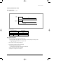
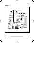
6-3 Circuit Description
6-3-1 Indoor Fan Control
ZERO CROSSING PARTS
FM1
FM2
■
Use SSR(Solid State Relay) of Micom to change the ON Time until the 220V sine wave equals the fan motor rpm to control. In the
meantime, the Zero Crossing part will recognize AC220V as 0V to determine the Switching Timing.
As the Fan Control Port of Micom detects the "High" signal and the signal turns into "Low" past TR-Array(UL2003), the LED of SSR
obtains 12V, the same input wave with "2" and the Gate of Photo Triac obtains the operating voltage at the same time to determine
the time to turn on SSR. Now the indoor fan motor can operate at the desired rpm.
■
For 2-Way, control two fans simultaneously.(FM1, FM2)
High RPM
Low RPM
Voltage
Voltage
Current
Current
Samsung Electronics
49
DB98_16890A(2)_1
5/10/04 2:09 PM
Page 50
Feature & Operation
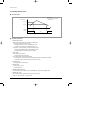
6-3-2 Stepping Motor Control
S1
M
S4
S2
S3
■
As shown in the above figure, let the electric currents in sequence flow through the 4 windings to revolve the stepping motor. Of 3
methods of 4 couple stepping switch sequence, 1 Phase Exciter Method, 2 Phase Exciter Method, and 1-2 Phase Exciter Method,
the last method was adopted for this circuit. Based on this method, the signals come in the order of S1, S2, S3, and S4 to create
magnetic force and one frequency forms a cycle. When S1, S2, S3, and S4 receive the following signals respectively, the stepping
motor begins operation.
Power OFF (Closing) CCW ("1"=HIGH)
Power ON (Opening) CW ("0"=LOW)
Switch
1
2
3
4
5
6
7
8
1
2
3
4
5
6
7
8
1
1
0
0
0
0
0
0
S1
0
0
0
0
0
1
1
1
0
1
1
1
0
0
0
0
S2
0
0
0
1
1
1
0
0
0
0
0
1
1
1
0
0
S3
0
1
1
1
0
0
0
0
0
0
0
0
0
1
1
1
S4
1
1
0
0
0
0
0
0
Power OFF
50
Power ON
S1
S1
S2
S2
S3
S3
S4
S4
Samsung Electronics
DB98_16890A(2)_1
5/10/04 2:09 PM
Page 51
7. Set Up the Model Option
7-1 Setting Option Setup Method
ex) Option No. :
Step 1 : Enter the Option Setup mode.
1st
Take out the batteries of remote control.
2nd
Press the temp.
button simultaneously and
insert the battery again.
3rd
Make sure the remote control display shown as
.
Step 2 : Enter the Option Setup mode and select your option according to the following procedure.
1
The default value is
Otherwise, push the
.
button to
.
Every time you push the button, the display panel reads
or
repeatedly.
1
2
Push the
2
3
4
button to set the display panel to
.
Every time you push the button, the display panel reads
...
repeatedly.
3
Push the
button to set the display panel to
.
Every time you push the button, the display panel reads
...
repeatedly.
5
6
4
Push the
button to set the display panel to
.
Every time you push the button, the display panel reads
...
repeatedly.
5
Push the
button to set the display panel to
.
Every time you push the button, the display panel reads
...
repeatedly.
✳ Setting is not required if you must
a value which has a
default.
Samsung Electronics
6
Push the
button to set the display panel to
.
Every time you push the button, the display panel reads
...
repeatedly.
51
DB98_16890A(2)_1
5/10/04 2:09 PM
Page 52
Set up the Model Option
7
Press
button, then the default value is
.
8
Push the
button to set the display panel to
.
Every time you push the button, the display panel reads
...
repeatedly.
7
8
9
9
Push the
button to set the display panel to
.
Every time you push the button, the display panel reads
...
repeatedly.
10
11
10
Push the
12
button to set the display panel to
.
Every time you push the button, the display panel reads
...
repeatedly.
11
Push the
button to set the display panel to
.
Every time you push the button, the display panel reads
...
repeatedly.
12
✳ Setting is not required if you must
a value which has a
default.
Push the
button to set the display panel to
.
Every time you push the button, the display panel reads
...
repeatedly.
Step 3 : Upon completion of the selection, check you made right selections.
Press the Mode Selection key,
to set the display part to and check the display part.
The display part shows
.
Press the Mode Selection key,
The display part shows
to set the display part to
and check the display part.
.
Step 4 : Pressing the ON/OFF button (
)
When pressing the operation ON/OFF key with the direction of remote control for unit, the sound ''Ding'' or ''Diriring'' is
heard and the OPERATION ICON( ) lamp of the display is flickering at the same time, then the input of option is completed. (If the diriring sound isn't heard, try again pressing the ON/OFF button.)
Step 5 : Unit operation test-run
First, Remove the battery from the remote control.
Second, Re-insert the battery into the remote control.
Third, Press ON/OFF button( ) with the direction of remote control for set.
• Error Mode
1st If all lamps of indoor unit are flickering, Plug out, plug in power plug again and press ON/OFF key to retry.
2nd If the unit is not working properly or all lamps are continuously flickering after setting the option code, see if the correct option code is
set up for its model.
52
Samsung Electronics
DB98_16890A(2)_1
5/10/04 2:09 PM
Page 53
Set up the Model Option
■ OPTION ITEMS
REMOTE
CONTROL SEG1
SEG2
SEG3
SEG4
SEG5
SEG6
SEG7
SEG8
SEG9 SEG10 SEG11 SEG12
MODEL
GH052EAM
0
2
5
4
4
2
1
A
0
3
7
1
GH070EAM
0
2
5
4
4
2
1
c
0
3
8
2
Samsung Electronics
53
DB98_16890A(2)_1
5/10/04 2:09 PM
Page 54
8. Troubleshooting
■ Detection of errors
● If an error occurs during the operation, one or more LED flickers and the operation is stopped except the LED.
● If you re-operate the air conditioner, it operates normally at first, then detect an error again.
8-1 LED Display on the indoor unit
Indicators
Abnormal conditions
Operating
Green
Red
Power reset
Error of temp. sensor in indoor unit
(OPEN/SHORT)
Displayed on appropriate indoor unit
which is operating
Error of heat exchanger sensor in indoor unit
Displayed on appropriate indoor unit
which is operating
Error of outdoor temp. sensor
Error of COND sensor
Error of DISCHARGE sensor
Displayed on appropriate indoor unit
which is operating
Displayed on outdoor unit
1. No communication for 2 minutes between
indoor unit and outdoor unit
(communication error for more than
2 minutes)
2. Indoor unit receiving the communication error
from outdoor unit
3. Outdoor unit tracking 3 minute error
4. When sending the communication error from
outdoor unit the mismatching of the
communication numbers and installed
numbers after completion of tracking.(communication error for more than 2 minutes)
1. Error of indoor unit: Displayed on
the indoor unit regardless of
operation
2. Error of outdoor unit: Displayed on
the indoor unit which is operating
Communication error between indoor units
Self-diagnostic error
(including the indoor unit not detected)
1. Error of electronic expansion valve close
2. Error of electronic expansion valve open
3. 2nd detection of high temp. COND
4. 2nd detection of high temp.
DISCHARGE
5. Error of reverse phase
6. Compressor down due to 6th detection of
freezing
Displayed on appropriate indoor unit
which is operating
Displayed on outdoor unit
Error of float switch
Error of setting option switches for optional
accessories
EEPROM error
EEPROM option error
- If you turn off the air conditioner when the LED is flickering, the LED is also turned off.
- If you re-operate the air conditioner, it operates normally at first, then detect an error again.
54
: On
: Flickering
: Off
Samsung Electronics
DB98_16890A(2)_1
5/10/04 2:10 PM
Page 55
8-2 Outdoor Unit
If an error occurs during the operation, it is displayed on the outdoor unit PCB.
Display
Explanation
High temp. of Discharge (Protection control)
Remark
Error about protection
control of outdoor unit
High temp. of outdoor heat exchanger (Protection control)
COMP DOWN to protect being frozen
Error of momentary power failure (disappears when the unit is Off/On)
Error of OUT TEMP. sensor (OPEN/SHORT)
Error of temp. sensor in outdoor heat exchanger (OPEN/SHORT)
Errors about outdoor unit
sensor (OPEN/SHORT)
Detection during the
operation of indoor unit
(Sensing and sending errors
into the communication data)
Error of Discharge TEMP. sensor (OPEN/SHORT)
System Down caused by communication error after completion of tracking
Communication and
indoor unit errors
Mismatching of the indoor unit numbers set with those
communicated after completion of tracking
Error of float switch in indoor unit
Self-diagnosis of indoor and
outdoor unit (x:indoor unit
address)
Error of setting option switches for optional accessories
x
OPEN/SHORT error of room sensor in indoor unit
x
OPEN/SHORT error of evap in sensor in indoor unit
x
Error of fan starting
Displays of operating status
Open error of electronic expansion valve in outdoor unit
(Detected once or more times)
Close error of electronic expansion valve in outdoor unit
(Detected once or more times)
Flicker
Below -5°C when cooling (Outdoor temp.)
Flicker
Over 30°C when heating (Outdoor temp.)
K1, K2, K3, K4,
K5 Flicker
Refer to page 15
The order of priority : E1 → E2 → E4 → P0 → P1 → P5 → P6 → t1 → t2 → t3 → tu → to → G4 → G5 → E3 → qx → rx → vx →
K1, K2, K3, K4, K5
The order of priority : - In case that the same error displays from multi-indoor units, the one having the faster address has the priority.
Samsung Electronics
55
DB98_16890A(2)_1
5/10/04 2:10 PM
Page 56
8-3 Wired remote controller
● If an error occurs,
is displayed on the wired remote controller.
● If you would like to see an error code, press the Test button.
Display
Description
Error of communication between the outdoor unit and the wired
remote controller
Remarks
Communication errors
Error of communication between the indoor unit and the wired
remote controller
x
Open error of electronic expansion valve
x
Close error of electronic expansion valve
x
Error of float switch
x
OPEN/SHORT error of room sensor in indoor unit
x
OPEN/SHORT error of eva in sensor in indoor unit
x
EEPROM error
x
EEPROM option error
Error of outdoor unit
Displays related to indoor unit
(x : 0~F)
For the details, refer to the
installation manual of the
outdoor unit.
The order of priority : EA → Eb → Cx → dx → ox → qx → rx → tx → Ux → Eo
- In case that the same error displays from multi-indoor units, the one having the faster address has the priority.
56
Samsung Electronics
DB98_16890A(2)_1
5/10/04 2:10 PM
Page 57
8-4 Sequence for trouble diagnosis
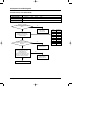
8-4-1 Outdoor temp. sensor(OPEN/SHORT)
Outdoor unit display
Er → t1 (Outdoor temp. sensor OPEN/SHORT error)
(Operation)
Indoor unit display
How to determine
Reason of error
(Timer)
(Airflow)
(Filter)
Disconnection and short of outdoor temp. sensor
Disconnection or leak of applied sensor
Is not separated the out
temp. sensor connector from PCB?
(CN41)
No
Reoperation
after connect to
connector PCB
Yes
To measure the resistance value
between two terminals after
separating the out temp. sensor
connector from PCB
At this time, Is largely
deviate the resistance value from side
table value?
Yes
Resistance
(kΩ)
70
2.2
60
3.0
50
4.2
40
5.8
30
8.3
20
12.1
10
18.0
0
27.3
-10
43.0
Outdoor unit thermistor
is defective(replace)
No
Check the out temp.
sensor is normal or not by use of
out data display part
➞ Check the temp. data is
normal or not after pressing K4 3 times.
At this time, is occurred the difference
between the out temp. and data?
Temp.
(˚C)
No
PCB and sensor are normal.
To perform the test
operation by use of K2
Yes
Reoperation after PCB replacement
Samsung Electronics
57
DB98_16890A(2)_1
5/10/04 2:10 PM
Page 58
Troubleshooting
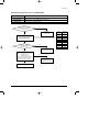
8-4-2 Outdoor heat exchanger temp. sensor error(OPEN/SHORT)
Outdoor unit display
Er → t2 (Outdoor heat exchanger temp. sensor error(OPEN/SHORT)
(Operation)
Indoor unit display
How to determine
Reason of error
(Timer)
(Airflow)
(Filter)
Disconnection and short of outdoor heat exchanger temp. sensor
Disconnection or leak of Applied sensor
Is not separated the out
heat exchanger temp. sensor
connector from PCB?(CN41)
No
Reoperation
after connect to
connector PCB
Yes
To measure the resistance value
between two terminals after separating
the out heat exchanger temp.
sensor connector from PCB
Yes
At this time, Is largely
deviate the resistance value from side
table value?
Yes
Yes
Resistance
(kΩ)
70
2.2
60
3.0
50
4.2
40
5.8
30
8.3
20
12.1
10
18.0
0
27.3
-10
43.0
Outdoor heat exchanger
temp. is defective(replace)
No
Check the out temp.
sensor is normal or not by use of
out data display part
➞ Check the temp. data is
normal or not after pressing K4 2 times.
At this time, is occurred the difference
between the out temp. and data?
Temp.
(˚C)
No
PCB and sensor are
normal.
To perform the test
operation by one of K2
Reoperation after PCB replacement
58
Samsung Electronics
DB98_16890A(2)_1
5/10/04 2:10 PM
Page 59
Troubleshooting
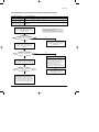
8-4-3 Outdoor discharge temp. sensor error(OPEN/SHORT)
Outdoor unit display
Er → t3 (Outdoor discharge temp. sensor OPEN/SHORT error)
(Operation)
Indoor unit display
How to determine
Reason of error
(Timer)
(Airflow)
(Filter)
Disconnection and short of outdoor discharger temp. sensor
Disconnection or leak of Applied sensor
Is not separated the outdoor
discharge temp. sensor connector
from PCB?(CN42)
No
Reoperation
after connect to
connector PCB
Yes
To measure the resistance value
between two terminals after separating
the outdoor discharge temp.
sensor connector from PCB
Yes
At this time, Is largely
deviate the resistance value from
side table value?
Yes
Yes
Resistance
(kΩ)
130
8.9
120
11.2
100
18.5
80
32
60
59
25
200
20
242
10
362
0
553
Outdoor heat exchanger
temp. is defective(replace)
No
Check the out temp.
sensor is normal or not by use of out
data display part
➞ Check the temp. data is
normal or not after pressing K4 1 times.
At this time, is occurred the difference
between the out temp. and data?
Temp.
(˚C)
No
PCB and sensor are normal.
To perform the test
operation by use of K2
Reoperation after PCB replacement
Samsung Electronics
59
DB98_16890A(2)_1
5/10/04 2:10 PM
Page 60
Troubleshooting
8-4-4 Communication error during the operation
Outdoor unit display
Er → E1 (Communication error during the operation)
(Operation)
Indoor unit display
How to determine
Reason of error
(Timer)
(Airflow)
(Filter)
Disconnection and short of communication lines
Communication error between the indoor unit and outdoor unit.
To check the display after
pressing the reset key on outdoor PCB
Multi type
After 2 minutes, to check if PCB address
setting of indoor unit displayed the
communication error among indoor units are
overlapped or not.
(If the indoor unit address is overlapped, the
communication error is occurred.)
- In this case, the communication error is
occurred to over two indoor units set
wrong.
No
When tracking, is there any
indoor answer from display part?
Yes
To measure the 2 lines of outdoor side
by scope after removing the
communication line connecting from
outdoor unit to indoor unit.
If address is no fault,
to exchange the indoor unit PCB after
communication line check.
At this time, is the voltage
between lines spherical wave over DC ±0.7V
like below figure?
No
Yes
Replace PCB after checking
the outdoor unit communication line
and connector
After connecting again the communication
line connecting from outdoor unit to indoor unit,
to remove the communication
connector on indoor unit PCB, and find the
indoor unit preventing communication
through connecting the communication
connectors each by each, and then replace
the indoor unit PCB after line check.
Good
Bad
+0.7V
-0.7V
60
Samsung Electronics
DB98_16890A(2)_1
5/10/04 2:10 PM
Page 61
Troubleshooting
8-4-5 Communication error between indoor and outdoor after initial power input.
Outdoor unit display
Er → E2 (Tracking error)
(Operation)
Indoor unit display
How to determine
Reason of error
(Timer)
(Airflow)
(Filter)
Mismatching the communicating indoor unit and setting switch indoor numbers When outdoor tracking
Communication error between the indoor unit and outdoor unit, and installation number switch
setting miss
Check the setting value of
indoor unit installation number setting
switch of outdoor PCB and actual indoor unit
installation numbers
Is equal indoor unit actual
installation number and installation
number setting switch?
If the indoor unit number installed is one, set the
outdoor unit switch forward to "0", "1"
➞ "0" and "1" spell the connection of an indoor unit.
No
Yes
After setting the indoor unit installation setting
number switch correctly, re-perform the
tracking by pressing the reset key K3 of
outdoor unit PCB
Press the reset key K3 of outdoor unit
PCB and check the display to check the
number of indoor units answering to the
tracking
When tracking, is there any
indoor answer from display part?
Yes
To measure the 2 lines of outdoor unit side by
use of scope after removing the communication
line connecting from outdoor unit to indoor unit
At this time, is the voltage
between lines spherical wave over
DC ±0.7V?
Yes
No
Multi type
After 2 minutes, to check if PCB address setting
of indoor unit displayed the communication error
among indoor units is overlapped or not .
(If the indoor unit address is overlapped, the
communication error is occurred.)
- In this case, the communication error is
occurred to over two indoor units set wrong
If address is no fault,
to exchange the indoor unit PCB after
communication line check.
After connecting again the communication line
connecting from outdoor unit to indoor unit,
to check this communication is reverse or not,
and if there is no fault, to find the indoor unit
preventing communication through connecting
indoor units each by each, and then
exchange the indoor unit PCB after line check
Samsung Electronics
61
DB98_16890A(2)_1
5/10/04 2:10 PM
Page 62
Troubleshooting
8-4-6 Indoor float switching error
Outdoor unit display
Er → E3 (Indoor float switching error )
(Operation)
Indoor unit display
How to determine
Reason of error
(Timer)
(Airflow)
(Filter)
The status continues over 1 minute that indoor unit float switch is opened.
The rising of water level of drain pan due to the disorder of indoor unit drain pump,
the badness of detection sensor
Is the resistance value ∞
when measuring the resistance value
of two terminal after taking out the floating
switch connector connected to indoor
unit PCB? (Open status)
No
Re-assembly the floating switch
connector and perform the reset of
outdoor power(Required the reset of
indoor unit power)
Yes
Is the same error occurred?
No
Yes
Is much the water of drain pan ?
Replace the indoor unit PCB
Yes
No
Normal operation
Reset the indoor unit power
and check the drain pump operation
Check the floating switch bad.
Reset the indoor unit
power after replce
No
Does the drain pump operat?
Yes
Is the terminal voltage
of drain pump PCB about
AC 220V?
Does the water level decrease?
No
No
Yes
Yes
Replace the drain pump
Replace the indoor unit PCB
Normal operation
Replace the drain pump
62
❋ Note : E3 error should be released when
indoor unit power is reset.
Samsung Electronics
DB98_16890A(2)_1
5/10/04 2:10 PM
Page 63
MEMO
Samsung Electronics
63
DB98_16890A(2)_1
5/10/04 2:10 PM
Page 64
9. Exploded Views and Parts List
9-1 Indoor Unit
1-8
3
1-6
1-7
1-4
1-2
3-2
2
1-5
1-1
1
1-3
3-1
5
4
5-2
11
12
8
5-1
9
10
11
7
8
6
12
14
9
21
13
20
23
25
15
19
18
22
17
24
16
You can search for the updated part code
number through the ITSELF.
URL : http://itself.sec.samsung.co.kr
64
Samsung Electronics
DB98_16890A(2)_1
5/10/04 2:10 PM
Page 65
Exploded Views and Parts List
■
Parts List
No.
Code No.
Description
Q'TY
Specification
GH052EAM
GH070EAM
1
DB93-01811A
ASS'Y CONTROL BOX IN
ASS'Y
1
1
1-1
DB61-01482A
CASE CONTROL
PS(V0), BLK
1
1
1-2
DB61-01236A
BASE TERMINAL
SGCC-M
1
1
1-3
DB93-01480A
ASS'Y MAIN PCB
ASS'Y PCB
1
1
1-4
DB93-01481A
SUB PCB
PCB
1
1
1-5
DB26-10065B
TRANS POWER
1
1
1-6
DB93-01783A
ASS'Y TERMINAL BLOCK 4P
DAF 4P
1
1
1-7
DB93-01784A
ASS'Y TERMINAL BLOCK 6P
DAF S6P
1
1
1-8
DB61-00250A
CLAMP WIRE
NY
2
2
2
DB63-00779A
COVER CONTROL
HIPS
1
1
3
DB91-00232A
ASS'Y DRAIN PAN
ASS'Y DRAIN
1
1
3-1
DB63-00062A
RUBBER DRAIN CAP
NBR
1
1
3-2
DB71-50025A
WIRE HOLDER
NY
1
1
4
DB63-00672A
COVER SIDE LF
PP(INCOMBUSTIBLE), BLK
1
1
5
DB96-02754A
ASS'Y EVAP
FP 1.5 SLIT 3x10
-
1
DB96-03496A
ASS'Y EVAP
FP 1.3 SLIT 2x10
1
-
DB96-02753A
ASS'Y TUBE COLLECTOR
12.7ø
-
1
DB96-03325A
ASS'Y TUBE COLLECTOR
9.52ø
1
-
DB96-02752A
ASS'Y INLET PART
6.35ø CAPI 2.0ø
-
1
DB96-03324A
ASS'Y INLET PART
6.35ø CAPI 2.0ø
1
-
5-1
5-2
6
DB94-00040S
ASS'Y C-F-FAN
ø95 8 ranks, AS+G/F 20%
2
2
7
DB31-00241A
MOTOR ASSY
PFS040AVEB
2
2
8
DB90-01182A
ASS'Y COVER MOTOR
HIPS, INSU
2
2
HIPS, INSU
2
2
2
2
9
DB90-01184A
ASS'Y CASE MOTOR
10
DB95-00131F
ASS'Y SENSOR FLOAT
11
DB90-01183A
ASS'Y COVER EVAP GUIDE
HIPS, INSU
2
2
12
DB90-01185A
ASS'Y CASE FAN SIDE SUB
HIPS, INSU
2
2
13
DB94-00066A
ASS'Y BEARING
BEARING
2
2
14
DB61-01475A
GUIDE CONTROL
HIPS
1
1
15
DB31-00207A
DRAIN PUMP
KS1003SAC
1
1
16
DB61-01293A
HOLDER DRAIN PUMP
HIPS
1
1
17
DB73-00022B
RUBBER DRAIN PUMP
HIPS(HB), BLK
4
4
18
DB94-00371A
ASS'Y DRAIN SOCKET
ASS'Y
1
1
19
DB69-00137A
BAND RING
STS304
1
1
20
DB69-00695A
CUSHION BODY
EPS(GRY)
2
2
21
DB61-01468A
CLIP BRUSH
EPS(GRY)
4
4
22
DB64-00778A
CABINET BASE
SGCC-M 0.7T
1
1
23
DB64-00781A
CABI SIDE RH
SGCC-M 0.7T
1
1
24
DB64-00780A
CABI SIDE LF
SGCC-M 0.7T
1
1
25
DB61-00712A
HOLDER CABI SIDE
SGCC-M 1.0T
4
4
Samsung Electronics
65
DB98_16890A(2)_1
5/10/04 2:10 PM
Page 66
9-2 Panel
7
1
6
12
10
20
8
11
14
9
13
19
16
15
18
17
2
3
4
5
21
66
22
Samsung Electronics
DB98_16890A(2)_1
5/10/04 2:10 PM
Page 67
Exploded Views and Parts List
■
Parts List
No.
Code No.
Description
Q'TY
Specification
PG103M
PG103M1
PG103M2
1
DB64-00777A
PANEL FRONT
ABS
1
1
1
2
DB64-00775A
GRILLE FRONT
ABS
1
1
1
3
DB64-00774A
FILTER INLET AIR
ASS'Y
2
2
2
4
DB61-01297A
CASE OUTLET AIR
HIPS
2
2
2
5
DB66-00415A
BLADE H
HIPS
2
2
2
6
DB66-00402A
BLADE V
PP
16
16
16
7
DB66-00416A
LINK BLADE V
PP
4
4
4
8
DB66-00755A
LATCH DC
ASS'Y
3
3
3
9
DB63-00676A
COVER PANEL
HIPS
1
1
1
10
DB70-00031A
PLATE HANGER
STS304
2
2
2
11
DB31-10153D
MOTOR STEP
ASS'Y
2
2
2
12
DB61-00535A
HOLDER MOTOR
HIPS V0 BLK
2
2
2
13
DB39-00874C
C/W MOTOR STEP LONG
UL1007
1
1
1
14
DB39-00874B
C/W MOTOR STEP SHORT
UL1007
1
1
1
15
DB93-01666A
PCB DISPLAY
1
1
1
16
DB39-00875A
C/W DISPLAY
UL1007
1
1
1
17
DB64-00745A
INLAY WINDOW
PC
1
1
1
18
DB64-00746A
INLAY BUTTON
ABS
1
1
1
19
DB61-01238A
CASE LED PCB
ABS
1
1
1
20
-
CABLE CLAMP
4N
2
2
2
21
DB97-00871D
ASS'Y WIRED REMOCON
WIRED
-
1
-
22
DB97-00387F
ASS'Y WIRELESS REMOCON
WIRELESS
-
-
1
Samsung Electronics
67
DB98_16890A(2)_1
5/10/04 2:10 PM
Page 68
9-3 Outdoor Unit
20
1
2
21
22
15
23
16
5
4
24
8
13
25
9-7
9-1
9-3
10
3
11
9-6
9
9-2
9-5
14
12
9-4
17
19
26
18
6
7
68
Samsung Electronics
DB98_16890A(2)_1
5/10/04 2:10 PM
Page 69
Exploded Views and Parts List
■
Parts List
No.
Code No.
Description
Q'TY
Specification
UH052EAMT UH070EAMT
1
DB90-01363A
ASS'Y-COVER TOP
ASS'Y
1
1
2
DB90-01388A
ASS'Y CABINET-FRONT
ASS'Y
1
1
3
DB67-00140A
FAN-PROPELLER
AS+GF20%,OD460,3BLADE
1
1
1
4
DB61-01167A
BRACKET-MOTOR
SGCC-M,T1.6
1
5
DB90-00940B
ASS'Y-PARTITION
ASS'Y
1
1
6
DB95-00455A
ASS'Y COMP
SIAM,NN29VACMT
-
1
DB95-00454A
ASS'Y COMP
SIAM,NN21VBAMT
1
-
DB95-30013T
ASS'Y HEATER COMP
40W
1
1
7
8
DB31-00216A
MOTOR-FAN
OSEM-886SRC(S509)
-
1
DB31-00027G
MOTOR-FAN
OSEM-906SRC(S507)
1
-
DB93-02410A
ASS'Y CONTROL OUT
ASS'Y
-
1
DB93-02410B
ASS'Y CONTROL OUT
ASS'Y
1
-
9-1
DB26-10070A
TRANS-POWER
AC230V,DC17V
1
1
9-2
DB65-00112A
TERMINAL BLOCK-6P
35A 4P,25A 2P
1
1
9-3
3501-001204
RELAY POWER
MUF20CF,2A
1
1
9-4
DB61-30625A
BRACKET-TERMINAL
SGCC-M
1
1
9-5
DB93-40264E
ASS'Y CONTROL BOX OUT
ASS'Y
1
1
9-6
DB61-00152A
CASE-PCB-OUT
T2.5,ABS,BLK
1
1
9-7
2301-001369
C-FILM
3uF/450VAC
1
1
10
2501-001236
C-OIL
30uF/450VAC
-
1
2501-001235
C-OIL
25uF/450VAC
-
1
2501-001240
C-OIL
50uF/450VAC
1
-
9
11
DB32-00021F
THERMISTOR
AWG22,L470,L550
1
1
12
DB32-00071C
THERMISTOR
AWG22,L600
1
1
13
DB61-01685A
BRACKET-CAPACITOR
SGCC-M
-
1
DB69-60008A
BAND-CAPACITOR
SGCC-M
1
-
14
DB93-01855K
ASS'Y PCB MAIN
CEILING OUTDOOR PCB
1
-
DB93-01855J
ASS'Y PCB MAIN
CEILING OUTDOOR PCB
-
1
15
DB90-40176D
ASS'Y COVER CONTROL
ASS'Y
1
1
16
DB90-01189B
ASS'Y-ASS'Y CABI SIDE RH
ASS'Y
1
1
17
DB62-01471A
INSULATION-CLOTH COMP
UH070EAMT
-
1
DB62-02295A
INSULATION-CLOTH COMP
UH052EAMT
1
-
18
19
DB96-02876A
ASS'Y 4WAY VALVE
ASS'Y
-
1
DB96-02877A
ASS'Y 4WAY VALVE
ASS'Y
1
-
DB96-02896A
ASS'Y EEV VALVE
ASS'Y
-
1
DB96-02896B
ASS'Y EEV VALVE
ASS'Y
1
-
20
DB63-00613A
GUARD-COND
SECC-P,T1.6
1
1
21
DB61-01221A
GUIDE-SCREEN
P.E.H 100%,T2.5,1015x615,BLK
1
1
22
DB63-00320A
GUARD-FAN
HSWR,460
1
1
23
DB96-02849A
ASS'Y COND UNIT
UH070EAMT,UH052EAMT
1
1
24
DB96-02936A
ASS'Y COLLECTOR IN
ASS'Y
1
1
25
DB96-02937A
ASS'Y COLLECTOR OUT
ASS'Y
1
1
26
DB90-01291A
ASS'Y CABINET BASE OUT
ASS'Y
1
1
Samsung Electronics
69
DB98_16890A(2)_1
5/10/04 2:10 PM
Page 70
10. Block Diagram
Up and down STEP MOTOR
Room temp. SENSOR
pipe sensor
pipe outlet sensor
MAIN PCB
Indoor left and right FAN RPM
feedback control
Function display part remote control
receiving part
Option saving control
MICOM
Communication(485comm)
Indoor unit ADDRESS setting part
485 comm control
RMC ADDRESS setting part
Blackout restoring function
Room temp. compensation function
Power source comm wrong
connection prevention function
Central controller
Vent fan control
-
70
- Wire remote controller
- Relay
- Central controller
485 comm applied, room temp. compensation
EEPROM option saving and blackout restoring function
Left and right FAN MOTOR phase control
Power-comm line misconnection prevention function
Cost saving related sub-option separation between indoor unit communication part
Option part sub-development according to the SVC structure
Samsung Electronics
DB98_16890A(2)_1
5/10/04 2:10 PM
Page 71
11. PCB Diagram
11-1 Indoor Unit(Code No : DB93-01480A)
■ TOP
Samsung Electronics
71
DB98_16890A(2)_1
5/10/04 2:10 PM
Page 72
PCB Diagram
■ BOTTOM
72
Samsung Electronics
DB98_16890A(2)_1
5/10/04 2:10 PM
Page 73
PCB Diagram
■
Parts List
Location No.
Description
Specification
Q'TY
BD71
DIODE-BRIDGE
DF06S,600V,1A,SMD-4,TP
1
BZ61
BUZZER-PIEZO
70dB,3V,-,2KHz,BK
1
C101
C-AL
2200uF,20%,35V,GP,TP,16x25,7.5
1
C102
C-CER,CHIP
100nF,+80-20%,50V,Y5V,TP,2012
1
C103
C-AL
2200uF,20%,25V,GP,TP,16x25,7.5
1
C104
C-CER,CHIP
100nF,+80-20%,50V,Y5V,TP,2012
1
C105
C-AL
470uF,20%,25V,GP,TP,10x12.5mm
1
C110
C-FILM,MPPF
100nF,10%,275V,BK,18x6x12,15
1
C111
C-FILM,MPPF
100nF,10%,275V,BK,18x6x12,15
1
C201
C-CER,CHIP
100nF,+80-20%,50V,Y5V,TP,2012
1
C202
C-CER,CHIP
100nF,+80-20%,50V,Y5V,TP,2012
1
C203
C-CER,CHIP
100nF,+80-20%,50V,Y5V,TP,2012
1
C204
C-CER,CHIP
10nF,+80-20%,50V,Y5V,TP,2012
1
C205
C-CER,CHIP
10nF,+80-20%,50V,Y5V,TP,2012
1
C301
C-CER,CHIP
10nF,+80-20%,50V,Y5V,TP,2012
1
C302
C-CER,CHIP
100nF,+80-20%,50V,Y5V,TP,2012
1
C303
C-CER,CHIP
100nF,+80-20%,50V,Y5V,TP,2012
1
C304
C-CER,CHIP
100nF,+80-20%,50V,Y5V,TP,2012
1
C305
C-CER,CHIP
100nF,+80-20%,50V,Y5V,TP,2012
1
C306
C-CER,CHIP
100nF,+80-20%,50V,Y5V,TP,2012
1
C401
C-CER,CHIP
100nF,+80-20%,50V,Y5V,TP,2012
1
C402
C-CER,CHIP
100nF,+80-20%,50V,Y5V,TP,2012
1
C403
C-CER,CHIP
100nF,+80-20%,50V,Y5V,TP,2012
1
C404
C-CER,CHIP
100nF,+80-20%,50V,Y5V,TP,2012
1
C501
C-CER,CHIP
100nF,+80-20%,50V,Y5V,TP,2012
1
C502
C-CER,CHIP
100nF,+80-20%,50V,Y5V,TP,2012
1
C503
C-CER,CHIP
100nF,+80-20%,50V,Y5V,TP,2012
1
C504
C-CER,CHIP
100nF,+80-20%,50V,Y5V,TP,2012
1
C505
C-CER,CHIP
100nF,+80-20%,50V,Y5V,TP,2012
1
C506
C-CER,CHIP
10nF,+80-20%,50V,Y5V,TP,2012
1
C507
C-CER,CHIP
10nF,+80-20%,50V,Y5V,TP,2012
1
C601
C-AL
47uF,20%,50V,GP,TP,6.3x11,2.5
1
C805
C-CER,CHIP
100nF,+80-20%,50V,Y5V,TP,2012
1
C806
C-CER,CHIP
100nF,+80-20%,50V,Y5V,TP,2012
1
C808
C-CER,CHIP
100nF,+80-20%,50V,Y5V,TP,2012
1
C901
C-CER,CHIP
1nF,10%,50V,X7R,TP,2012,-
1
C902
C-CER,CHIP
100nF,+80-20%,50V,Y5V,TP,2012
1
C911
C-CER,CHIP
10nF,+80-20%,50V,Y5V,TP,2012
1
C912
C-CER,CHIP
10nF,+80-20%,50V,Y5V,TP,2012
1
C913
C-CER,CHIP
10nF,+80-20%,50V,Y5V,TP,2012
1
C914
C-CER,CHIP
10nF,+80-20%,50V,Y5V,TP,2012
1
C915
C-CER,CHIP
10nF,+80-20%,50V,Y5V,TP,2012
1
CD31
DIODE-TVS
SAC5.0,7.6/-/-V,500W,DO-15
1
CD32
DIODE-TVS
SAC5.0,7.6/-/-V,500W,DO-15
1
CN11
CONNECTOR-HEADER
BOX,3P,1R,2.5mm,STRAIGHT,SN
1
CN31
CONNECTOR-HEADER
1WALL,2P,1R,3.96mm,STRAIGHT,SN
1
CN33
CONNECTOR-HEADER
BOX,5P,1R,2mm,STRAIGHT,SN
1
CN41
CONNECTOR-HEADER
BOX,4P,1R,2.5mm,STRAIGHT,SN
1
CN42
CONNECTOR-HEADER
BOX,2P,1R,2.5mm,STRAIGHT,SN
1
Samsung Electronics
73
DB98_16890A(2)_1
5/10/04 2:10 PM
Page 74
PCB Diagram
■
Parts List(cont.)
Location No.
Description
Specification
Q'TY
CN43
CONNECTOR-HEADER
1WALL,2P,1R,3.96mm,STRAIGHT,SN
1
CN51
CONNECTOR-HEADER
BOX,2P,1R,2.5mm,STRAIGHT,SN
1
CN52
CONNECTOR-HEADER
BOX,3P,1R,2.5mm,STRAIGHT,SN
1
CN53
CONNECTOR-HEADER
BOX,3P,1R,2.5mm,STRAIGHT,SN
1
CN60
CONNECTOR-HEADER
BOX,10P,1R,2mm,STRAIGHT,SN,NTR
1
CN61
CONNECTOR-HEADER
BOX,12P,1R,2mm,STRAIGHT,SN
1
CN71
CONNECTOR-HEADER
1WALL,2P,1R,7.92mm,STRAIGHT,SN,BL
1
CN72
CONNECTOR-HEADER
1WALL,3P,1R,7.92mm,STRAIGHT,SN,WH
1
CN73
CONNECTOR-HEADER
1WALL,3P,1R,7.92mm,STRAIGHT,SN,BL
1
CN74
CONNECTOR-HEADER
1WALL,2P,1R,7.92mm,STRAIGHT,SN,YE
1
CN75
CONNECTOR-HEADER
1WALL,2P,1R,7.92mm,STRAIGHT,SN,BL
1
CN76
CONNECTOR-HEADER
1WALL,2P,1R,7.92mm,STRAIGHT,SN,WH
1
CN91
CONNECTOR-HEADER
BOX,9P,1R,2mm,STRAIGHT,SN
1
CR71
C-FILM,MPPF
1.2uF,10%,450Vac,BK,38x18x30,3
1
CR72
C-FILM,MPPF
1.2uF,10%,450Vac,BK,38x18x30,3
1
D105
DIODE-RECTIFIER
1N4007,1KV,1A,DO-41,TP
1
F701
FUSE-CARTRIDGE
250V,3.15A,TIME-LAG,GLASS,5x20mm
1
F702
FUSE
250V,1.6A,TIME-LAG,PLASTIC,8.4x7.6mm
1
FT71
LS404190M
AS-S660,19MH,+50,-30%,-,300Mohm,2A,-,-,-
1
IC01
IC-POSI.FIXED REG.
7812,TO-220,3P,-,PLASTIC,11.5/1
1
IC02
IC-POSI.FIXED REG.
7805,TO-220,3P,-,PLASTIC,4.8/5
1
IC03
IC-VOLTAGE COMP.
7533,TO-92,3P,-,SINGLE,-,-,PLASTIC
1
IC04
IC MICOM
MB89538AP-101,MB89538AP-101,64P,+5V,10MHZ
1
IC05
TR-ARRAY
2003,NPN,7,1W,SOP-16,ST,1000
1
IC06
TR-ARRAY
2003,NPN,7,1W,SOP-16,ST,1000
1
IC08
TR-ARRAY
2003,NPN,7,1W,SOP-16,ST,1000
1
IC19
IC-BUS TRANSCEIVER
485,DIP,8P,300MIL,SINGLE,ST,PLASTIC
1
IC51
IC-EEPROM
93LC56,128x16,SOP,8P,5x4mm,2.5/6.0V,-40
1
LED01
LED
TR,LED,1PCS,130-260%
1
LED02
LED
ROUND,YEL,5mm,585nm
1
Q201
TR-SMALL SIGNAL
2SC2412K,NPN,200mW,SOT-23,TP,1
1
Q202
TR-SMALL SIGNAL
2SC2412K,NPN,200mW,SOT-23,TP,1
1
Q501
TR-SMALL SIGNAL
2SC2412K,NPN,200mW,SOT-23,TP,1
1
Q502
TR-SMALL SIGNAL
2SC2412K,NPN,200mW,SOT-23,TP,1
1
Q601
TR-SMALL SIGNAL
2SC2412K,NPN,200mW,SOT-23,TP,1
1
Q602
TR-SMALL SIGNAL
2SC2412K,NPN,200mW,SOT-23,TP,1
1
Q603
TR-SMALL SIGNAL
MMST2907A,PNP,200mW,SOT-23,TP,100
1
Q901
TR-DIGITAL
DTA114EKA,PNP,200MW,10K/10K,SOT-23,TP
1
Q902
TR-DIGITAL
DTA114EKA,PNP,200MW,10K/10K,SOT-23,TP
1
Q903
TR-DIGITAL
DTA114EKA,PNP,200MW,10K/10K,SOT-23,TP
1
R04
R-CHIP
1Kohm,5%,1/8W,TP,2012
1
R201
R-CHIP
1Kohm,5%,1/8W,TP,2012
1
R202
R-CHIP
3.3Kohm,5%,1/8W,TP,2012
1
R203
R-CHIP
10Kohm,5%,1/8W,TP,2012
1
R204
R-CHIP
1Kohm,5%,1/8W,TP,2012
1
R205
R-CHIP
1Kohm,5%,1/8W,TP,2012
1
R206
R-CHIP
1Kohm,5%,1/8W,TP,2012
1
R301
R-CHIP
120ohm,5%,1/8W,TP,2012
1
R302
R-CHIP
10Kohm,5%,1/8W,TP,2012
1
74
Samsung Electronics
DB98_16890A(2)_1
5/10/04 2:10 PM
Page 75
PCB Diagram
■
Parts List(cont.)
Location No.
Description
Specification
Q'TY
R303
R-CHIP
10Kohm,5%,1/8W,TP,2012
1
R401
R-CHIP
6.8Kohm,1%,1/8W,TP,2012
1
R402
R-CHIP
6.8Kohm,1%,1/8W,TP,2012
1
R403
R-CHIP
6.8Kohm,1%,1/8W,TP,2012
1
R404
R-CHIP
6.8Kohm,1%,1/8W,TP,2012
1
R405
R-CHIP
330ohm,5%,1/8W,TP,2012
1
R406
R-CHIP
330ohm,5%,1/8W,TP,2012
1
R407
R-CHIP
330ohm,5%,1/8W,TP,2012
1
R408
R-CHIP
330ohm,5%,1/8W,TP,2012
1
R501
R-CHIP
1Kohm,5%,1/8W,TP,2012
1
R502
R-CHIP
6.8Kohm,5%,1/8W,TP,2012
1
R503
R-CHIP
1Kohm,5%,1/8W,TP,2012
1
R504
R-CHIP
1Kohm,5%,1/8W,TP,2012
1
R505
R-CHIP
6.8Kohm,5%,1/8W,TP,2012
1
R506
R-CHIP
1Kohm,5%,1/8W,TP,2012
1
R507
R-CHIP
10Kohm,5%,1/8W,TP,2012
1
R508
R-CHIP
330ohm,5%,1/8W,TP,2012
1
R511
R-CHIP
47Kohm,5%,1/8W,TP,2012
1
R512
R-CHIP
47Kohm,5%,1/8W,TP,2012
1
R601
R-CHIP
1Kohm,5%,1/8W,TP,2012
1
R602
R-CHIP
10Kohm,5%,1/8W,TP,2012
1
R603
R-CHIP
1Kohm,5%,1/8W,TP,2012
1
R604
R-CHIP
470ohm,5%,1/8W,TP,2012
1
R605
R-CHIP
470ohm,5%,1/8W,TP,2012
1
R606
R-CHIP
560ohm,5%,1/8W,TP,2012
1
R607
R-CHIP
1Kohm,5%,1/8W,TP,2012
1
R608
R-CHIP
10Kohm,5%,1/8W,TP,2012
1
R609
R-CHIP
10Kohm,5%,1/8W,TP,2012
1
R610
R-CHIP
3.3Kohm,5%,1/8W,TP,2012
1
R813
R-CHIP
1Kohm,5%,1/8W,TP,2012
1
R814
R-CHIP
1Kohm,5%,1/8W,TP,2012
1
R815
R-CHIP
1Kohm,5%,1/8W,TP,2012
1
R816
R-CHIP
1Kohm,5%,1/8W,TP,2012
1
R901
R-CHIP
330ohm,5%,1/8W,TP,2012
1
R902
R-CHIP
1Kohm,5%,1/8W,TP,2012
1
R903
R-CHIP
10Kohm,5%,1/8W,TP,2012
1
R911
R-CHIP
10Kohm,5%,1/8W,TP,2012
1
R912
R-CHIP
10Kohm,5%,1/8W,TP,2012
1
R913
R-CHIP
10Kohm,5%,1/8W,TP,2012
1
R914
R-CHIP
10Kohm,5%,1/8W,TP,2012
1
R915
R-CHIP
10Kohm,5%,1/8W,TP,2012
1
RY01
RELAY-MINIATURE
12V,-,11.7MA,DPDT,4MS,4MS
1
RY71
RELAY-MINIATURE
12VDC,200MW,3000MA,1FORMA,10MS,10M
1
RY72
RELAY-MINIATURE
12VDC,200MW,3000MA,1FORMA,10MS,10M
1
SS71
SSR
12Vdc,-,2A,1mS,1mS
1
SS72
SSR
12Vdc,-,2A,1mS,1mS
1
VA71
VARISTOR
560V,2500A,17.5x7.5mm,TP
1
X301
RESONATOR-CERAMIC
10MHz,0.5%,TP,10.0x5.0x8.0mm
1
Samsung Electronics
75
DB98_16890A(2)_1
5/10/04 2:10 PM
Page 76
11-2 Outdoor Unit (Code No:DB93-01855K;UH052EAMT / DB93-01855J;UH070EAMT)
■ TOP
■ BOTTOM
✳ The figure of PCB Pattern is common UH052EAMT and UH070EAMT.
✳ Only part list is different from between UH052EAMT and UH070EAMT.
76
Samsung Electronics
DB98_16890A(2)_1
5/10/04 2:10 PM
Page 77
PCB Diagram
■
Parts List(UH052EAMT)
Location No.
Description
Specification
Q'TY
D201,D901~D916
DIODE-SWITCHING
RLS4148,100V,200MA,SOD-80C,TP
17
D101~D105
DIODE-RECTIFIER
1N4007,1000V,1A,DO-41,TP
5
CD31~CD32
DIODE-TVS
SAC5.0,7.6/-/-V,500W,DO-15
2
Q201
TR-SMALL SIGNAL
2SC2412K,NPN,200mW,SOT-23,TP,1
1
Q901~D904
TR-DIGITAL
DTA114EKA,PNP,200MW,10K/10K,SOT-23,TP
4
Q101
TR-DIGITAL
KSR1102,NPN,200MW,10K/10K,SOT-23,TP
1
IC05~IC07
IC-DARLINGTON DRIVER
KID65003AP,DIP,16PIN,300MIL,H
3
IC09
IC-BUS TRANSCEIVER
485,DIP,8P,300MIL,SINGLE,ST,PLASTIC
1
IC03
IC-VOLTAGE COMP.
7533,TO-92,3P,-,SINGLE,-,-,PLASTIC
1
IC01
IC-POSI.FIXED REG.
7812A,TO-220,3P,-,PLASTIC,11.5
1
IC02
IC-POSI.FIXED REG.
7805,TO-220,3P,-,PLASTIC,4.8/5
1
VA72,VA73
VARISTOR
470V,4500A,17x12mm,BK
2
VA71
VARISTOR
560V,2500A,17.5x7.5mm,TP
1
RJ03
R-CARBON
12Kohm,5%,1/4W,AA,TP,2.4x6.4mm
1
K13~K16,RJ01
R-CARBON
0ohm,5%,1/4W,AA,TP,2.4x6.4mm
5
R301
R-CHIP
120ohm,5%,1/8W,TP,2012
1
R201,R302,R303
R-CHIP
10Kohm,5%,1/8W,TP,2012
20
R-CHIP
18Kohm,1%,1/8W,TP,2012
2
R312~319,R513~R517
R901~R904
R402,R403
R203~R205,R905~R911
R-CHIP
1Kohm,5%,1/8W,TP,2012
10
R401
R-CHIP
24Kohm,1%,1/8W,TP,2012
1
R202
R-CHIP
3.3Kohm,5%,1/8W,TP,2012
1
R404~R406
R-CHIP
330ohm,5%,1/8W,TP,2012
3
C102,C104,C201
C-CER,CHIP
100nF,+80-20%,50V,Y5V,TP,2012
20
C202,C301,C901~C904
C-CER,CHIP
10nF,+80-20%,50V,Y5V,TP,2012
6
C105
C-AL
470uF,20%,25V,GP,TP,10x12.5mm
1
C101,C103
C-AL
1000uF,20%,35V,GP,TP,13x25,5
2
X501
RESONATOR-CERAMIC
10MHZ,0.5%,BK,8x3x5.5mm
1
FT71
FILTER-EMI AC LINE
250V,1A,UL/CSA/TUV/SEMKO,100000
1
C302~C308,C401~C403
C801~C804,C905~C907
K1~K4
SWITCH-PUSH
125V,1A,SPDT,ON-ON,-
4
SW02,SW03
SWITCH-DIP
5V DC,100mA,SLIDE,-
2
RY71~RY77
RELAY-MINIATURE
12VDC,200MW,3000MA,1FORMA,10MS,10M
7
F701_1
FUSE-CARTRIDGE
250V,5A,FAST-ACTING,GLASS,5.2x20mm
1
F101
FUSE
250V,1.6A,TIME-LAG,PLASTIC,8.4x7.6mm
1
F701
FUSE-BLOCK
500V,-,100M
1
CN42
CONNECTOR-HEADER
BOX,2P,1R,2.5mm,STRAIGHT,SN,WHT
1
CN12
CONNECTOR-HEADER
1WALL,2P,1R,3.96mm,STRAIGHT,SN
1
Samsung Electronics
77
DB98_16890A(2)_1
5/10/04 2:10 PM
Page 78
PCB Diagram
■
Parts List(UH052EAMT)(cont.)
Location No.
Description
Specification
Q'TY
CN31
CONNECTOR-HEADER
1WALL,2P,1R,3.96mm,STRAIGHT,SN
1
CN77
CONNECTOR-HEADER
1WALL,2P,1R,7.92mm,STRAIGHT,SN,WH
1
CN72
CONNECTOR-HEADER
1WALL,3P,1R,7.92mm,STRAIGHT,SN,BL
1
CN73
CONNECTOR-HEADER
1WALL,3P,1R,7.92mm,STRAIGHT,SN,WH
1
CN75
CONNECTOR-HEADER
1WALL,4P,1R,7.92mm,STRAIGHT,SN,WH
1
CN70
CONNECTOR-HEADER
BOX,1P,1R,6mm,STRAIGHT,NI,WHT
1
CN11
CONNECTOR-HEADER
BOX,3P,1R,2.5mm,STRAIGHT,SN
1
CN41
CONNECTOR-HEADER
BOX,4P,1R,2.5mm,STRAIGHT,SN
1
CN61
CONNECTOR-HEADER
BOX,5P,1R,2.5mm,STRAIGHT,SN
1
CN60
CONNECTOR-HEADER
BOX,6P,1R,2.5mm,STRAIGHT,SN
1
CN71
CONNECTOR-HEADER
1WALL,2P,1R,7.92mm,STRAIGHT,SN,BL
1
CN74
CONNECTOR-HEADER
1WALL,2P,1R,7.92mm,STRAIGHT,SN,YE
1
GT-2
CONNECTOR-TERMINAL
PIN,MALE,#18-22,2.35mm
1
DIS1
LED DISPLAY-7SEG
ELD-306GWA,-,2,14,-,15x15.5x7.2,G
1
DIS2
LED DISPLAY-7SEG
ELD-306GWA,-,2,14,-,15x15.5x7.2,G
1
IC04
IC MICOM
MB89538AP-101,MB89538AP-101,64P,+5V,10MHz
1
SW1
SWITCH-DIGITAL
PT65 103,ROTARY DIP,-,DC24V MAX,0.4
1
DS71
POSISTOR
DSA-332MA,2pF MAX,100Mohm,ASM-3
1
RJ01
R-CARBON
0ohm,1/4W,2.4x6.4mm
1
RJ02
R-CARBON
8.2Kohm,5%,1/4W,AA,TP,2.4x6.4mm
1
RJ03
R-CARBON
12Kohm,5%,1/4W,AA,TP,2.4x6.4mm
1
RJ04
R-CARBON
18Kohm,5%,1/4W,AA,TP,2.4x6.4mm
1
78
Samsung Electronics
DB98_16890A(2)_1
5/10/04 2:10 PM
Page 79
PCB Diagram
■
Parts List(UH070EAMT)
Location No.
Description
Specification
Q'TY
D201,D901~D916
DIODE-SWITCHING
RLS4148,100V,200MA,SOD-80C,TP
17
D101~D105
DIODE-RECTIFIER
1N4007,1000V,1A,DO-41,TP
5
CD31,CD32
DIODE-TVS
SAC5.0,7.6/-/-V,500W,DO-15
2
Q201
TR-SMALL SIGNAL
2SC2412K,NPN,200mW,SOT-23,TP,1
1
Q901~Q904
TR-DIGITAL
DTA114EKA,PNP,200MW,10K/10K,SOT-23,TP
4
Q101
TR-DIGITAL
KSR1102,NPN,200MW,10K/10K,SOT-23,TP
1
IC05~IC07
IC-DARLINGTON DRIVER
KID65003AP,DIP,16PIN,300MIL,H
3
IC09
IC-BUS TRANSCEIVER
485,DIP,8P,300MIL,SINGLE,ST,PLASTIC
1
IC03
IC-VOLTAGE COMP.
7533,TO-92,3P,-,SINGLE,-,-,PLASTIC
1
IC01
IC-POSI.FIXED REG.
7812A,TO-220,3P,-,PLASTIC,11.5
1
IC02
IC-POSI.FIXED REG.
7805,TO-220,3P,-,PLASTIC,4.8/5
1
VA72,VA73
VARISTOR
470V,4500A,17x12mm,BK
2
VA71
VARISTOR
560V,2500A,17.5x7.5mm,TP
1
K13~K16,RJ01
R-CARBON
0ohm,5%,1/4W,AA,TP,2.4x6.4mm
5
R301
R-CHIP
120ohm,5%,1/8W,TP,2012
1
R201,R302~R303
R-CHIP
10Kohm,5%,1/8W,TP,2012
20
R402,R403
R-CHIP
18Kohm,1%,1/8W,TP,2012
2
R203~R205,R905~R911
R-CHIP
1Kohm,5%,1/8W,TP,2012
10
R401
R-CHIP
24Kohm,1%,1/8W,TP,2012
1
R202
R-CHIP
3.3Kohm,5%,1/8W,TP,2012
1
R404~R406
R-CHIP
330ohm,5%,1/8W,TP,2012
3
C102,C104,C201
C-CER,CHIP
100nF,+80-20%,50V,Y5V,TP,2012
20
C202,C301,C901~C904
C-CER,CHIP
10nF,+80-20%,50V,Y5V,TP,2012
6
C105
C-AL
470uF,20%,25V,GP,TP,10x12.5mm
1
C101,C103
C-AL
1000uF,20%,35V,GP,TP,13x25,5
2
X501
RESONATOR-CERAMIC
10MHZ,0.5%,BK,8x3x5.5mm
1
FT71
FILTER-EMI AC LINE
250V,1A,UL/CSA/TUV/SEMKO,100000
1
K1~K4
SWITCH-PUSH
125V,1A,SPDT,ON-ON,-
4
SW02,SW03
SWITCH-DIP
5V DC,100mA,SLIDE,-
2
RY71,R76,R77
RELAY-MINIATURE
12VDC,200MW,3000MA,1FORMA,10MS,10M
3
RY72~RY75
RELAY-MINIATURE
12VDC,200MW,5000MA,1FORMA,10MS,5MS
4
F701_1
FUSE-CARTRIDGE
250V,5A,FAST-ACTING,GLASS,5.2x20mm
1
F101
FUSE
250V,1.6A,TIME-LAG,PLASTIC,8.4x7.6mm
1
F701
FUSE-BLOCK
500V,-,100M
1
CN42
CONNECTOR-HEADER
BOX,2P,1R,2.5mm,STRAIGHT,SN,WHT
1
CN12
CONNECTOR-HEADER
1WALL,2P,1R,3.96mm,STRAIGHT,SN
1
R312~R319,R513~R517
R901~R904
C302~C308,C401~C403
C801~C804,C905~C907
Samsung Electronics
79
DB98_16890A(2)_1
5/10/04 2:10 PM
Page 80
PCB Diagram
■
Parts List(UH070EAMT)(cont.)
Location No.
Description
Specification
Q'TY
CN31
CONNECTOR-HEADER
1WALL,2P,1R,3.96mm,STRAIGHT,SN
1
CN77
CONNECTOR-HEADER
1WALL,2P,1R,7.92mm,STRAIGHT,SN,WH
1
CN72
CONNECTOR-HEADER
1WALL,3P,1R,7.92mm,STRAIGHT,SN,BL
1
CN73
CONNECTOR-HEADER
1WALL,3P,1R,7.92mm,STRAIGHT,SN,WH
1
CN75
CONNECTOR-HEADER
1WALL,4P,1R,7.92mm,STRAIGHT,SN,WH
1
CN70
CONNECTOR-HEADER
BOX,1P,1R,6mm,STRAIGHT,NI,WHT
1
CN11
CONNECTOR-HEADER
BOX,3P,1R,2.5mm,STRAIGHT,SN
1
CN41
CONNECTOR-HEADER
BOX,4P,1R,2.5mm,STRAIGHT,SN
1
CN61
CONNECTOR-HEADER
BOX,5P,1R,2.5mm,STRAIGHT,SN
1
CN60
CONNECTOR-HEADER
BOX,6P,1R,2.5mm,STRAIGHT,SN
1
CN71
CONNECTOR-HEADER
1WALL,2P,1R,7.92mm,STRAIGHT,SN,BL
1
CN74
CONNECTOR-HEADER
1WALL,2P,1R,7.92mm,STRAIGHT,SN,YE
1
GT-2
CONNECTOR-TERMINAL
PIN,MALE,#18-22,2.35mm
1
DIS1
LED DISPLAY-7SEG
ELD-306GWA,-,2,14,-,15x15.5x7.2,G
1
DIS2
LED DISPLAY-7SEG
ELD-306GWA,-,2,14,-,15x15.5x7.2,G
1
IC04
IC MICOM
MB89538AP-101,MB89538AP-101,64P,+5V,10MHz
1
SW1
SWITCH-DIGITAL
PT65 103,ROTARY DIP,-,DC24V MAX,0.4
1
DS71
POSISTOR
DSA-332MA,2pF MAX,100MOhm,ASM-3
1
RJ01
R-CARBON
0ohm,5%,1/4W,AA,TP,2.4x6.4mm
1
RJ02
R-CARBON
8.2Kohm,5%,1/4W,AA,TP,2.4x6.4mm
1
RJ03
R-CARBON
18Kohm,5%,1/4W,AA,TP,2.4x6.4mm
1
RJ04
R-CARBON
33Kohm,5%,1/4W,AA,TP,2.4x6.4mm
1
80
Samsung Electronics
DB98_16890A(2)_1
5/10/04 2:10 PM
Page 81
12. Wiring Diagram
12-1 Indoor Unit
Code No : DB98-09029A
This Document can not be used without Samsung's authorization.
Samsung Electronics
81
DB98_16890A(2)_1
5/10/04 2:10 PM
Page 82
12-2 Outdoor Unit
■ UH052EAMT
Code No : DB98-14410A
This Document can not be used without Samsung's authorization.
82
Samsung Electronics
DB98_16890A(2)_1
5/10/04 2:10 PM
Page 83
Wiring Diagram
■ UH070EAMT
Code No : DB98-14410B
This Document can not be used without Samsung's authorization.
Samsung Electronics
83
DB98_16890A(2)_1
5/10/04 2:10 PM
Page 84
13. Schematic Diagram
13-1 Indoor Unit
This Document can not be used without Samsung's authorization.
84
Samsung Electronics
DB98_16890A(2)_1
5/10/04 2:10 PM
Page 85
13-2 Outdoor Unit
■ UH052EAMT
This Document can not be used without Samsung's authorization.
Samsung Electronics
85
DB98_16890A(2)_1
5/10/04 2:10 PM
Page 86
Schematic Diagram
■ UH070EAMT
This Document can not be used without Samsung's authorization.
86
Samsung Electronics
DB98_16890A(2)_1
5/10/04 2:10 PM
Page 87
MEMO
Samsung Electronics
87
DB98_16890A(2)_1
5/10/04 2:10 PM
Page 88
MEMO
88
Samsung Electronics
DB98_16890A(2)_Co
5/10/04 2:07 PM
Page 2
ELECTRONICS
This Training Manual is a property of Samsung Electronics Co., Ltd.
Any unauthorized use of Manual can be punished under applicable
International and/or domestic law.
© Samsung Electronics Co., Ltd. May. 2004.
Printed in Korea.
Code No. DB98-16890A(2)