1
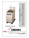
Decathlon Series Gas Fryers
Installation, Operation & Maintenance Manual
D20, D50, D60 & D80 Series
Dean, a member of the Commercial Food Equipment Service Association, recommends using
CFESA Certified Technicians.
24-Hour Service Hotline 1-800-551-8633
Price: $8.00
819-5698
10-00
Please read all sections of this manual and retain for future
reference.
This product has been certified as commercial cooking equipment and MUST be
installed by professional personnel as specified. Installation, maintenance and repairs
should be performed by your DEAN FACTORY AUTHORIZED SERVICE CENTER.
CAUTION
Do not store or use gasoline or other flammable vapors and liquids in the vicinity of this
or any other cooking appliance.
CAUTION
Instructions explaining procedures to be followed MUST be posted in a prominent
location in the event the operator detects a gas leak. This information can be obtained
from the local gas company or gas supplier.
WARNING
Improper installation, adjustment, alteration, service or maintenance can cause property
damage, injury or death. Read the installation, operating and maintenance instructions
thoroughly before installing or servicing this equipment.
WARNING
Safe and satisfactory operation of your equipment depends on proper installation.
Installation MUST conform with local codes, or in absence of local codes, with the
National Fuel Gas Code, ANSI Z223.1; The Natural Gas Installation Code, CAN/CGAB149.1; or The Propane Installation Code, CAN/CGA-B149.2.
CAUTION
The crumb tray in fryers equipped with a filter system must be emptied into a fireproof
container at the end of frying operations each day. Some food particles can
spontaneously combust if left soaking in certain shortening material. Additional
information can be obtained in the filtration manual included with the system.
WARNING
SAFE AND SATISFACTORY OPERATION OF YOUR EQUIPMENT DEPENDS ON ITS
PROPER INSTALLATION. INSTALLATION MUST CONFORM TO LOCAL CODES, OR IN
THE ABSENCE OF LOCAL CODES, WITH THE LATEST EDITION OF THE NATIONAL
ELECTRIC CODE, N.F.P.A. 70.
i
Decathlon Series Gas Fryers
TABLE OF CONTENTS
Page #
1.
INTRODUCTION
1-1
2.
IMPORTANT INFORMATION
2-1
3.
INSTALLATION INSTRUCTIONS
3-1
4.
FRYER OPERATIONS
4-1
5.
COMPU-FRY/THERMATRON INSTRUCTIONS
5-1
6.
PREVENTATIVE MAINTENANCE
6-1
7.
TROUBLESHOOTING
7-1
8.
PARTS LIST
8-1
ii
DECATHLON SERIES GAS FRYERS
CHAPTER 1: INTRODUCTION
1.1 After Purchase:
In order to improve service, have the following chart filled in by the Dean Authorized Service
Technician who installed this equipment.
Authorized Service
Technician/FASC
Address
Telephone/Fax
Model Number
Serial Number
Gas Type
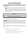
1.2 Ordering Parts:
Customers may order parts directly from their local factory authorized service center. For this address
and phone number, contact your factory authorized service center or call the Dean Industries Service
Hotline phone number, 1-800-551-8633.
To speed up your order, provide the model number, serial number, gas type, part needed, item part
number (if known), and quantity needed.
1.3 Service Information:
Call the Dean Service Hotline, 1-800-551-8633, for the location of your nearest factory authorized
service center. To assist you more efficiently, always provide the service technician with the model
number, gas type, serial number, and the nature of the problem.
1.4 Safety Information
Before attempting to operate your unit, read the instructions in this manual thoroughly.
Throughout this manual, you will find notations enclosed in double-bordered boxes similar to the ones
below.
CAUTION boxes contain information about actions or conditions that may cause or result in a
malfunction of your system.
1-1
CAUTION
Example of a CAUTION box.
WARNING boxes contain information about actions or conditions that may cause or result in damage
to your system, and which may cause your system to malfunction.
WARNING
Example of a WARNING box.
DANGER boxes contain information about actions or conditions that may cause or result in injury to
personnel, and which may cause damage to your system and/or cause your system to malfunction.
DANGER
Hot cooking oil causes severe burns. Never attempt to move a fryer containing hot cooking oil
or to transfer hot cooking oil from one container to another.
1-2
DECATHLON SERIES GAS FRYERS
CHAPTER 2: IMPORTANT INFORMATION
2.1 Product Description
The Dean Industries Decathlon Fryers are energy-efficient, tube-style, gas-fired units, design-certified
by the International Approval Services (AGA/CGA), National Sanitation Foundation (NSF), and
manufactured to their basic performance and application specifications.
All units are shipped completely assembled with accessories packed inside the fryer vessel. All units
are adjusted, tested and inspected at the factory before shipment. Sizes, weights and input rates of all
models are listed in this manual.
NOTE: The on-site supervisor is responsible for ensuring that operators are made aware of inherent
dangers of operating a deep fat fryer, particularly aspects of oil filtration, draining, and
cleaning of the fryer.
2.2 Principles of Operation
The incoming gas flows through orifices and is mixed with air in the burners to create the correct ratio
for proper combustion. The mixture is ignited at the front end of each heat tube by the pilot light.
Internal diffusers slow the flame as it goes through the burner tube. This slower and more turbulent
flame gives much better heat transfer to the walls of the tubes, thereby heating the oil better.
2.3 Rating Plate
This is attached to the inside right-hand corner of the front door panel. Information provided includes
the model and serial number of the fryer, BTU/hr input of the burners, outlet gas pressure in inches WC
and whether the unit has natural or propane gas orifices.
DANGER
Fryers MUST be connected ONLY to the gas type identified on the attached rating
plate.
2.4 Pre-Installation
A. General: Only a licensed gas fitter should install any gas-fired equipment.
1.
A manual gas shut-off valve must be installed in the gas supply line ahead of the fryers for
safety and ease of future service.
2-1
2.
The Dean Decathlon gas fryers require 120 VAC 60 cycle or 230VAC single-phase 50-hertz
(International/CE) electrical service and are equipped with a 16-3 SJT grounded flexible power
cord for a direct connection to the power supply. Amperage draw for each unit depends on the
accessories supplied with the unit. See detailed instructions packaged with the fryer.
B. Clearances: The fryer area must be kept free and clear of all combustibles. This unit is designcertified for the following installations:
1.
Commercial installation only (not for household use).
2.
Non-combustible floor installation equipped with factory-supplied 6-inch (15-cm) adjustable
legs or 5-inch (13-cm) casters;
3.
Combustible construction with a minimum clearance of 6-inches (15-cm) side and 6-inches (15cm) rear, and equipped with factory-supplied 6-inch (15-cm) adjustable legs or 5-inch (13-cm)
casters.
CAUTION
Local building codes usually prohibit a fryer with its open tank of hot oil from being installed
beside an open flame of any type, whether a broiler or the open burner of a range.
C. Installation Standards:
1. U.S. installations must meet:
2. Canadian installations must meet:
American National Standard Institute
ANSI Z83.11
American Gas Association
8501 E. Pleasant Valley Road
Cleveland, OH 44131
CAN 1-B149 Installation Codes
Canadian Gas Association
55 Scarsdale Road
Don Mills, ONT, M3B 2R3
National Electrical Code
ANSI/NFPA #70
American National Standard Institute
1430 Broadway
New York, NY 10018
Canadian Electric Code c22.1, part 1
Canadian Standards Association
178 Rexdale Blvd.
Rexdale, ONT, M9W 1R3
NFPA Standards #96 and #211
National Fire Protection Association
470 Atlantic Avenue
Boston, MA 02110
3. CE/EXPORT STANDARDS: Fryer installation must conform with local codes, or in the absence of
local codes, to the appropriate national or European Community (CE) standards.
2-2
2.5 Air Supply and Ventilation
Keep the area around the fryer clear to prevent obstruction of combustion and ventilation airflow as well
as for service and maintenance.
A. Do not connect this fryer to an exhaust duct.
B. Correct installation and adjustment will ensure adequate airflow to the fryer system.
C. A commercial, heavy-duty fryer must vent its combustion wastes to the outside of the building.
A deep-fat fryer must be installed under a powered exhaust hood, or an exhaust fan must be
provided in the wall above the unit, as exhaust gas temperatures are approximately 800-1000°F
(427-538°C). Check air movement during installation. Strong exhaust fans in the exhaust hood
or in the overall air conditioning system can produce slight air drafts in the room.
D. Do not place the fryer’s flue outlet directly into the plenum of the hood, as it will affect the gas
combustion of the fryer.
E. Never use the interior of the fryer cabinet for storage or store items on shelving over or behind
the fryer. Exhaust temperatures can exceed 425ºC and may damage or melt items stored in or
near the fryer.
F. Adequate distance must be maintained from the flue outlet of the fryer(s) to the lower edge of
the filter bank. Per NFPA Standards No. 96, a minimum of 18-inches (45-cm) should be
maintained between the flue(s) and the lower edge of the exhaust hood filter.
G. Filters and drip troughs should be part of any industrial hood, but consult local codes before
constructing and installing any hood. The duct system, the exhaust hood and the filter bank
must be cleaned on a regular basis and kept free of grease.
2.6 Equipment Installed at High Altitudes:
A. The fryer input rating (BTU/hr) is for elevations up to 2,000 feet (610-m). For elevations above
2,000 feet (610-m), the rating should be reduced four percent (4) for each additional 1,000 feet
(305-m) above sea level.
B. The correct orifices are installed at the factory if operating altitude is known at time of the
customer’s order.
2.7 Receiving and Unpacking Equipment:
A. Check that the container is upright. Use an outward prying motion - no hammering - to remove
the carton. Unpack the fryer carefully and remove all accessories from the carton. Do not
discard or misplace these, as they will be needed.
B. After unpacking, immediately check the equipment for visible signs of shipping damage. If
damage has occurred, contact the carrier and file the appropriate freight claims. Do not contact
the factory. Shipping damage responsibility is between the carrier and the dealer.
2-3
If your equipment arrives damaged:
1. File claim for damages immediately, regardless of extent of damage.
2. Visible loss or damage: Be sure this is noted on the freight bill or express receipt and is
signed by the person making the delivery.
3. Concealed loss or damage: If damage is unnoticed until equipment is unpacked, notify freight
company or carrier immediately, and file a concealed damage claim. This should be done
within fifteen (15) days of date of delivery. Be sure to retain container for inspection.
NOTE: Dean Does Not Assume Responsibility for Damage or Loss Incurred in Transit.
C. Take off the filter support brace and remove the filter pan from the cabinet of the two left fryers.
D. Casters are pre-installed on the fryer unit and the carton is furnished with three unloading ramps.
Remove the braces from the front casters by taking out the securing bolts. Carefully roll the unit
down the ramps from the front (cooking side).
E. Remove all plastic skin from sides, front, and doors of the unit. Failure to do this will melt the
plastic and make it very difficult to remove later.
2-4
DECATHLON SERIES GAS FRYERS
CHAPTER 3: INSTALLATION
3.1
Installing the Fryer
A. Initial Installation: If the fryer is installed with legs, do not push the fryer to adjust its
position. Use a pallet or lift jack to lift the fryer slightly, then place the fryer where it is to be
installed.
B. Relocating the fryer: Remove all weight from each leg before moving a fryer with legs
installed. Do not slide the fryer on the legs.
C. If a leg becomes damaged, contact your service agent for immediate repair/replacement.
3.2 Leveling the Fryer (Fryers equipped with legs only)
A. All Installations: If the floor is uneven or has a definite slope, it is recommended to place
the fryer on an even platform.
B. Place a carpenter’s spirit level across the top of the fryer and level the unit both front-to-back
and side-to-side. If it is not level, the unit may not function efficiently, the oil may not drain
properly for filtering and in a line-up it may not match adjacent units.
C. Adjust to the high corner and measure with the spirit level. If floor is uneven, level the unit
with the screw adjustments on each leg (ensure minimum clearances as discussed in
Chapter 2 are maintained during the leveling procedure).
D. Re-leveling: If the fryer is moved, re-level the fryer following the above instructions.
E. The install must be reviewed at the time of installation to ensure it meets the intent of these
instructions.
CAUTION
Fryers must be at room temperature, empty of oil, and if fitted with legs lifted during
movement to avoid damage and possible bodily injury.
WARNING
Hot shortening can cause severe burns. Avoid contact. Under all circumstances, oil
must be removed from the fryer before attempting to move it to avoid oil spills, and
the falls and severe burns that could occur. This fryer may tip and cause personal
injury if not secured in a stationary position. See instruction manual.
3-1
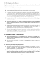
3.3 Installing Casters and Legs
A. Install casters and/or legs near where the fryer is to be used, as neither is secure for long
transit. The fryer cannot be curb mounted and must be equipped with either legs or casters
provided.
B. After unpacking, use a pallet or lift jack to raise the unit approximately 12 inches before
installing the casters.
C. Align the caster or leg base holes with the leg support assembly and insert bolt. Install the
washers and nut hand-tight, and repeat for all four holes in caster/leg base assembly.
D. Tighten the caster/leg against the leg support assembly by using appropriate tools. Ensure
that all four bolts are evenly tightened.
E. For fryers with casters, there are no built-in leveling devices. The floor where the fryers
are installed must be level.
Front View
Rear Side View
Optional CasterRear Only
Optional CasterFront Only
Rear Caster— 5" Rigid
Front Caster— 5" Swivel
w/Brake
1/4-20 x 3/4 Hex Bolt
Front Channel or
Rear Channel
Front Channel
or Rear Channel
Leg Support Assembly
Washer
1/4-20 Hex Head Locknut
Front or Rear Leg with
Mounting Plate
1/4-20 x 3/4 Hex Bolt
Adjust as needed
Caster/Leg Installation and Adjustment
WARNING
Dean fryers equipped with legs are for permanent installations. Fryers fitted with
legs must be lifted during movement to avoid damage and possible bodily injury. For
a moveable or portable installation, Dean optional equipment casters must be used.
Questions? Call 1-800-551-8633
3-2
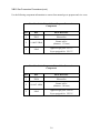
3.4 Gas Categories
Dean Decathlon Series Gas Fryers have obtained CE markings for countries and gas categories listed
in the table below:
Countries
Supply Pressures and Appliance
Gas (mbar)
Categories
G20
20/25
I2E (R) B
BE Belgium
ES
Spain
FR France
Supply Pressures and Appliance
Gas (mbar)
Categories
G20
20
G31
37 and 50
G20
20
G31
37
G20
20
G20/G25
20/25
G31
50
G25
25
G31
50
G20
20
G31
37
GR Greece
G31
37
I3P
G20
20
I2E
DE Germany
DK Denmark
Countries
IR
Ireland
G31
50
I3P
G20
20
I2H
IT
G20
20
G31
37 and 50
II2H3P
LU Luxembourg
G20/G25
20/25
G31
37 and 50
II2ESI3P
NL
The
Netherlands
G20
20
II2H3P
PT
Portugal
GB Great Britain
G31
37
II2H3P
Italy
II2H3P
I2H
II2E3P
II2L3P
II2H3P
3.5 Gas Connections
A. The gas supply (service) line must be the same size or greater than the fryer inlet line. This
fryer is equipped with a 3/4" (19 mm) male inlet. The gas supply line must be sized to
accommodate all the gas-fired equipment that may be connected to that gas supply. Consult
your contractor, gas company, supplier, or other knowledgeable authorities.
Recommended Gas Supply Line Sizes
Gas Types
Natural Gas
Propane Gas
Number of Fryers
2 to 3
1" (25 mm)
3/4" (19 mm)
1
3/4" (19 mm)
1/2" (13 mm)
4 or more (*)
1 1/4" (33 mm)
1" (25 mm)
(*) When exceeding 18 feet (6 meters) for a configuration of more than four fryers, it is necessary
to provide a 1 1/4" (33 mm) rigid gas connection.
CAUTION
All connections must be sealed with a joint compound suitable for the gas being
used, and all connections must be tested with a soapy solution before lighting any
pilots.
3-3
3.5 Gas Connections (cont.)
B. Rigid Connections: Check any installer-supplied intake pipe(s) visually and clean threading
chips, or any other foreign matter before installing into a service line. If the intake pipes are
not clear of all foreign matter, the orifices will clog when gas pressure is applied. Seal pipe
joints with a sealant resistive to LP gas. When using thread compound on gas piping, use
very small amounts and only on male threads. Use a pipe thread compound that is not
affected by the chemical action of LP gases. DO NOT apply thread compound to the first
two pipe threads--doing so will cause clogging of the burner orifices and control valve.
C. Manual shut-off valve: This gas service supplier-installed valve must be installed in the gas
service line ahead of the fryers in the gas stream and in a position where it can be reached
quickly in the event of an emergency.
D. Regulating Gas Pressure: The fryer and shut-off valve must be disconnected from the gas
supply during any pressure testing of the system.
1. External gas regulators are not normally required on this fryer. A safety control valve
protects the fryer against pressure fluctuations. If the incoming pressure is in excess of
½" PSI (3.45 kPa/35 mbar), a step-down regulator will be required.
CAUTION
The fryer must be isolated from the gas supply piping system by closing its
individual manual shut-off valve during any pressure testing of the gas supply piping
system at pressures equal to or less than ½ PSI (3.45 kPa/35 mbar).
The fryer and its individual shut-off valve must be disconnected from the gas supply
piping system during any pressure testing of the gas supply system at test
pressures in excess of ½ PSI (3.45 kPa/35 mbar).
E. Manifold Pressure: Your local service technician should check the manifold pressure with a
manometer.
1. Check the rating plate for manifold gas pressures. Natural gas units normally require 4"
W.C., and propane units normally require 11" W.C. gas pressure.
2. Double check the arrow forged into the bottom of the regulator body, which shows gas
flow direction. It should point downstream towards the fryers. The air vent cap is also
part of the regulator and should not be removed.
3. If a vent line from the gas pressure regulator is used, it should be installed in
accordance with local codes or in the absence of local codes, with the National Fuel
Gas Code, ANSI Z223.1-(latest edition).
3-4
3.5 Gas Connections (cont.)
WARNING
Use a diluted soap solution to find potentially dangerous gas leaks when making
new connections.
F. Regulators can be adjusted in the field, but it is recommended that they not be tampered with
unless the part is known to be out of adjustment or serious pressure fluctuations are found to
exist and can be solved no other way.
G. Only qualified service personnel should make adjustments to the regulators.
H. Orifices: The fryer can be configured to operate on any available gas. The correct safety
control valve, appropriate gas orifices, and pilot burner are installed at the factory. While the
valve can be adjusted in the field, only qualified service personnel should make any
adjustments with the proper test equipment.
WARNING
If gas odors are detected, the gas supply must be shut off at the main shut-off valve.
The local gas company or FASC should be contacted immediately to rectify the
problem.
I.
Flexible Couplings, Connectors and Casters:
1. If the fryer is to be installed with flexible couplings and/or quick-disconnect fittings, the
installer must use a heavy-duty AGA design-certified commercial flexible connector of
at least 3/4" NPT (with suitable strain reliefs), in compliance with the Standard for
Connectors for Movable Gas Appliances, ANSI Z21.69-(latest edition) and Addenda
Z21.69a-(latest edition). Quick disconnect devices must comply with the Standard for
Quick-Disconnect Devices for Use with Gas Fuel, ANSI Z21.41-(latest edition).
WARNING
Do not attach accessories to this fryer unless fryer is secured from tipping. Personal
injury may result.
2. The fryer must be restrained by means independent of the flexible coupling or
connector in order to limit the movement of the fryer. Clips are located on the back
panel of the fryer for the attachment of restraints.
3. If disconnection of the restraint is necessary, this restraint must be reconnected after the
fryer has been returned to its originally installed position.
3-5
3.5 Gas Connections (cont.)
J. After hook-up, bleed the gas line of air to ensure that the pilot light will ignite quickly.
K. CE Standards: If the unit is to be installed with flexible coupling, use a commercial flexible
coupling certified as NF D 36123 (or other national standard) or a quick disconnect device
certified NF D 36124 (or other national standard).
3.6 Adjustments/Adaptation To Different Gases
A. Proper operation of appliances requires operator to scrupulously inspect the following
adjustments in terms of:
1. Gas inputs and pressures.
2. Voltage and polarities of electrical power supplies.
B. Dean gas fryers are manufactured to use the type of gas and pressure specified on the rating
plate. When changing to a different gas, adaptation must be performed by qualified
personnel. Failure to use qualified personnel will void the Frymaster warranty.
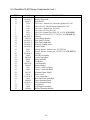
3.6.1 CE Specifications
3.6.1.1 Gas Types and Specifications
MODEL
INPUT
(kW)
D20G
15
D50G
D60G
D80G
30
37.5
37.5
EQUIPMENT
PRESSURE
MBAR
INCH WC
GAS
TYPE
ORIFICE
MM (INCH)
ORIFICE
PART NO.
QTY/
COLOR
PRESSURE
MBAR
PILOT
ASSEMBLY
G20
2.40(#42)
14-0067-10Blu
2/BLUE
10
G25
2.40(#42)
14-0067-10Blu
2/BLUE
15
4.0
20MBAR
14199-1CE
6.0
25MBAR
G31
1.51(#53)
14-0067-2Red
2/RED
14199-1CE
27
10.8
37MBAR
14199-2CE
G20
2.40(#42)
14-0067-10Blu
G25
2.40(#42)
14-0067-10Blu
4/BLUE
10
4.0
20MBAR
14199-1CE
4/BLUE
15
6.0
25MBAR
G31
1.51(#53)
14199-1CE
14-0067-2Red
4/RED
27
10.8
37MBAR
14199-2CE
G20
G25
2.40(#42)
14-0067-10Blu
5/BLUE
10
4.0
20MBAR
14199-1CE
2.40(#42)
14-0067-10Blu
5/BLUE
15
6.0
25MBAR
14199-1CE
G31
1.51(#53)
14-0067-2Red
5/RED
27
10.8
37MBAR
14199-2CE
G20
2.40(#42)
14-0067-10Blu
5/BLUE
10
4.0
20MBAR
14199-1CE
G25
2.40(#42)
14-0067-10Blu
5/BLUE
15
6.0
25MBAR
14199-1CE
G31
1.51(#53)
14-0067-2Red
5/RED
27
10.8
37MBAR
14199-2CE
3-6
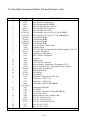
3.6.1.2 Adjustments to Different Gas Types
Gases and Gas Supply
Pressure*
G20
20 mbar
G25
25 mbar
G31
37/50 mbar
Orifice Diameter
2.40 mm
2.40 mm
1.51 mm
Burner Marking
"blue" marking
"blue" marking
TJ024
TJ024
"red" marking
TJ013
"red"
10
15
Pilot Marking
Gas pressure at
regulator (mbar)*
the
27
NOTE: Outlet gas pressure must be adjusted strictly within the above requirements 5 to 10 minutes
after the appliance is operating.
* For controls and adjustments, please refer to "gas valve" illustrations on page 3-8. (Pilot Flame
Adjustment: Turn the pilot adjustment screw clockwise/counter-clockwise until the desired flamevolume is achieved).
3.6.2 Gas Conversion Procedures
See page 3-8 for gas valve illustrations when performing the following conversions.
When converting from G20 to G25 gas, the following procedures apply:
♦
♦
♦
Equipment replacement is not required.
Adjust orifice gas pressure by turning the gas valve adjustment screw (See Section 3.6.1.1
for various gas types and pressures).
After adjustment, seal the screw.
When converting from G20 (or G25) gas to G31 propane (or vice-versa), the following procedures
apply:
♦
♦
♦
♦
Burner orifices and pilot MUST be replaced (See page 3-9 for required components).
Adjust orifice gas pressure by turning the gas-valve adjustment screw (See Section 3.6.1.1
for various gas types and pressures).
After adjustment, seal the screw.
Affix new label "fryer equipped for: <gas family/# mbar>" to the rating plate. Remove any
reference to the previously used gas from the rating plate.
When converting from G20 (20 mbar) to G25 (25 mbar), or vice-versa, or G31 (37 mbar) to G31 (50
mbar), the following procedures apply:
♦
♦
Check pilot-adjustment and adjust as necessary.
Other adjustments are not necessary.
3-7
3.6.2 Gas Conversion Procedures (cont.)
Conversion from one gas family to another (i.e. changing from natural gas to propane) requires
special components. Obtain the necessary components using the cross-reference tables on page 3-9.
Conversions can only be executed by qualified, factory-authorized personnel.
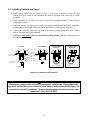
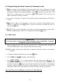
Pilot flow adjustment
Thermocouple connection
Vent tube connection
Pressure flow adjustment
OFF Button
ON Button- Pilot Gas-flow
CE Gas Valve
Pilot pressure adjustment
(remove cover screw to access)
Pressure flow adjustment
(remove cover screw to access)
Regulator Vent
Pilot gas supply connection.
ON/OFF Gas-Cock Knob
Non-CE Gas Valve
3-8
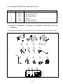
3.6.2 Gas Conversion Procedures (cont.)
Use the following component information to convert from natural gas to propane and vice-versa.
Decathlon Series Natural Gas to Propane Conversion
Components
QTY
REF
DESCRIPTION
1
TJ013
Pilot orifice
5
14-0067-2Red
Burner orifice
(diameter: 1.51 mm)
1
Label
Appareil réglé pour: G31/37
Fryer equipped for: G31/37
Decathlon Series Propane to Natural Gas Conversion
Components
QTY
REF
DESCRIPTION
1
TJ024
Pilot orifice
5
14-0067-10Blu
Burner orifice
(diameter: 2.40 mm)
1
Label
Appareil réglé pour: G20/20
Fryer equipped for: G25/25
3-9
3.7 Electrical Connections
The fryer when installed must be electrically grounded in accordance with local codes, or in the
absence of local codes, with the National Electrical Code, ANSI/NFPA 70-(latest edition).
WARNING
This fryer is equipped with a three-prong (grounding) plug for protection against
shock hazard. It should be plugged directly into a properly grounded, three-prong
receptacle. DO NOT CUT, REMOVE, OR OTHERWISE BYPASS THE GROUNDING
PRONG ON THIS PLUG.
The rating plate and wiring diagram are located inside the front door. The fryer is equipped with a
120VAC single-phase 60-hertz system (Domestic), or 230VAC single-phase 50-hertz system
(International/CE). Do not cut or remove the ground prong from the power cord plug. Do not
attempt to use the fryer during a power outage.
3-10
DECATHLON SERIES GAS FRYERS
CHAPTER 4: FRYER OPERATIONS
4.1 Initial Start-up
A. Cleaning: New units are wiped clean with solvents at the factory to remove any visible signs
of dirt, oil, grease, etc. remaining from the manufacturing process, then coated lightly with
oil. Before any food preparation, wash thoroughly with hot, soapy water to remove any film
residue and dust or debris then rinse out and wipe dry. Also wash any accessories shipped
with the unit. Close the drain-valve completely and remove the crumb screen covering the
heating tubes. Make sure the screws holding the thermostat and high-limit control sensing
bulbs into the vessel are tight.
CAUTION
Do not bang fry baskets or other utensils on the fryer’s joiner strip. The strip is
present to seal the joint between the fry vessels. Banging fry baskets on the strip to
dislodge shortening will distort the strip, adversely affecting its fit. It is designed for
a fit tight and should only be removed for cleaning.
4.1.1 Pilot Lighting Procedures, Standing Pilot Only
Initial Pilot Light: All Dean fryers are tested, adjusted and calibrated to sea level conditions before
leaving the factory. Adjustments to assure proper operation of pilot may be necessary on installation
to meet local conditions, low gas pressure, differences in altitude and variations in gas
characteristics. These adjustments correct possible problems caused by rough handling or vibration
during shipment, and are to be performed only by qualified service personnel. These adjustments
are the responsibility of the customer and/or the dealer and are not covered by the Dean Industries
warranty.
The inlet pipe at the lower rear of the fryer brings incoming gas to the pilot safety control valve, then
to the pilot and main burners. The pilot is located high in the cabinet center, at the base of the fryer
vessel.
Light the pilot as follows:
1. Turn off the manual shut-off valve on the incoming service line.
2. Turn the operating thermostat or the computer off.
3. Depress the pilot gas cock dial on the combination control valve and turn to "OFF".
4. Wait approximately 5 minutes for accumulated gas to disperse.
4-1
4.1.1 Pilot Lighting Procedures, Standing Pilot Only (cont.)
Note: Inspect high-limit thermostat/temperature probe location prior to filling fry
vessel with water or oil. Ensure that connecting hardware is intact and bulbs are
properly attached.
5. Fill the fry vessel with oil or water to the bottom OIL LEVEL line scribed on the vessel
back. Ensure that heating tubes are covered in liquid prior to engaging burners.
6. Open the manual shut-off valve on the incoming service line.
7. Apply lighted match or taper to the pilot burner head.
8. Turn the gas cock dial on the control valve to "Pilot", then depress and hold the dial until
the pilot stays lit (approximately 1 minute).
9. If the pilot fails to stay lit, depress the dial and re-light the pilot, depressing the dial
longer before releasing.
10. When the pilot stays lit, turn the gas cock dial to "ON".
11. Turn the operating thermostat, computer or controller on, then ensure the main burners
ignite from the pilot.
WARNING
When checking for burner ignition or performance, do not get too close to the
burners. Slow ignition can cause possible flashback, increasing the potential for
facial and body burns.
4.1.2 Pilot Lighting Procedures, Electronic Ignition Systems
WARNING
Never use a match or taper to light pilot on this ignition system.
1. Turn gas "ON".
2. Turn electric power "ON" with the appropriate rocker switch or controller/computer.
3. The electric module will turn on the pilot gas supply and the electric ignition spark. The
spark will ignite the pilot gas. The presence of the pilot flame is then proved by the
electric flame sensor, which in turn allows the main gas supply to be turned on. The
operating thermostat or computer/controller controls the fryer after ignition is proved.
4-2
4.1.2 Pilot Lighting Procedures, Electronic Ignition Systems (cont.)
WARNING
In the event of prolonged power failure, the ignition module will shut down and lock
out the system. Turn the unit power “OFF” and them back “ON” after power has
been re-established.
4. If the pilot flame fails, the ignition module will shut down and lock out the system. To
restart, turn the electric power "OFF", wait approximately 5 minutes for the system to
recycle itself, then turn the power "ON" again. Repeat Steps 1-3.
4.2 Boil-Out Procedure
4.2.1 Thermostat-Equipped Fryers
A. Pour cleaning solution into the fry vessel and add water to the bottom OIL LEVEL line
scribed in the back of the fry vessel.
B. Set the operating thermostat dial/temperature controller to 104ºC (219°F), just above that of
boiling water.
C. The main burner will ignite.
D. Reset the temperature controller to 93ºC (199.4°F).
E. The burners should shut-off just as the water starts to boil.
F. The burners will heat the boil-out solution to a simmer. Simmer the solution for
approximately 45 minutes. Wearing protective gloves, scrub the sides of the fry vessel and
the tubes with the L-shaped teflon brush, being careful not to disturb the temperature
sensing probes and the high-limit thermostat.
G. Do not allow the water level to decrease below the bottom OIL LEVEL line in fry vessel
during boil-out operation.
H. After boil-out is complete, turn the thermostat dial to "OFF" and drain the solution from the
fry vessel. Place a metal pan or bucket under the drain port to collect the water from the fry
vessel.
I.
Close the drain, add fresh water (without boil-out solution) and wash all surfaces of the fry
vessel. Drain again.
J.
Refill the fry vessel with fresh water and vinegar to neutralize any residual boil-out solution.
Wash all surfaces of the fry vessel. Drain completely and wipe down all surfaces of the fry
vessel to completely eliminate water from the vessel.
4-3
4.2.2 Filtration/Boil-Mode Option-Equipped Fryers
A. Pour cleaning solution into the fry vessel and add water to the bottom OIL LEVEL line
scribed in the back of the fry vessel.
B. Turn fryer power-switch "ON". Then press the fryer reset-switch.
CAUTION
If the pilot and main burner go out, the fryer(s) MUST be left completely shut down at
least 5 minutes before lighting.
C. Turn the boil-out switch "ON". The main burner will ignite. DO NOT LEAVE THE
FRYER UNATTENDED DURING THE BOIL-OUT PROCEDURE.
CAUTION
Do not leave fryer unattended. The boil-out solution may foam and overflow if fryer is
left unattended. Press ON/OFF switch to the "OFF" position to control this condition.
D. The burners will heat the boil-out solution to a simmer. Simmer the solution for
approximately 45 minutes. Wearing protective gloves, scrub the sides of the fry vessel and
the tubes with the L-shaped teflon brush, being careful not to disturb the temperature sensing
probes and the high-limit thermostat.
E. Do not allow the water level to decrease below the bottom OIL LEVEL line in fry vessel
during boil-out operation.
CAUTION
Water or boil-out solution MUST not be allowed to drain into the filter pan or filter
system. Irreversible damage will result if water is allowed into the system.
F. After boil-out is complete, turn the boil-out and fryer switches to "OFF" and drain the
solution from the fry vessel. Place a metal pan or bucket under the drain port to collect the
water from the fry vessel. DO NOT DRAIN THE WATER INTO THE FILTER PAN.
The filter pump is not designed for water operation, and will be irreparably damaged.
G. Close the drain, add fresh water (without boil-out solution) and wash all surfaces of the fry
vessel. Drain again.
H. Refill the fry vessel with fresh water and vinegar to neutralize any residual boil-out solution.
Wash all surfaces of the fry vessel. Drain completely and wipe down all surfaces of the fry
vessel to completely eliminate water from the vessel.
4-4
4.2.2 Filtration/Boil-Mode Option-Equipped Fryers (cont.)
CAUTION
All drops of water MUST be removed from fry vessel before filling with cooking oil.
Do not turn fryer on to dry… extensive damage will occur to fry vessel and burner
tubes, and ALL warranties will be voided.
NOTE: For a fresh start and prolonged fry vessel life, it is recommended that the boil-out procedure
be performed each time the oil/shortening is changed.
4.2.3 Computer-Equipped Fryers
A. Before switching the fryer(s) "ON", close the fry-vessel drain-valve(s). Fill the empty fry
vessel with a mixture of cold water and boil-out solution. Follow instructions when mixing.
B. To program computer for Boil Feature, press either
C. Press the
switch.
switch.
will appear in the left display.
D. Enter
(1 6 5 3) in that sequence. The right display will read
. The
temperature is automatically set for 195°F (91°C). The fryer will attain this temperature and
remain there until either
switch is pressed, which cancels the boil-out mode. In highaltitude locations, constantly monitor the fryer for over-boil conditions. If over-boil occurs,
turn off fryer immediately, allow to cool, and re-enter boil-out mode to continue the boil-out
operation.
4.3 Final Preparation
WARNING
NEVER set a complete block of solid shortening on top of heating tubes. To do so
will damage the heating tubes and fry vessel, and void the warranty.
4.3.1 Filling Fryer with Cooking Oil/Shortening— Operating Thermostat/Thermatron
A. When using a liquid shortening (cooking oil), fill the fryer to the bottom OIL LEVEL line
scribed into the back of the fryer vessel.
B. When using a solid shortening, first melt it in a suitable container, or cut it into small pieces
and pack it below the heat tubes, between the tubes and on top of the tubes, leaving no air
spaces around the tubes. Do not disturb or bend the sensing bulbs.
4-5
C. If equipped with a Melt Cycle Control, turn the melt cycle switch "ON" to melt the
shortening. The burners will cycle on and off until shortening has melted.
D. If the fryer does not have a Melt Cycle Control, turn the burners "ON" for about 10 seconds,
"OFF" for a minute, etc., until the shortening is melted. If you see smoke coming from the
shortening while melting this way, shorten the "ON" cycle and lengthen the "OFF" cycle.
Smoke indicates potential scorching of the shortening, which will shorten its useful life.
E. Before starting operation, turn the operating thermostat to the probable working
temperature; wait for the temperature to stabilize then check with a high-quality immersion
thermometer.
4.3.2 Filling Fryer with Cooking Oil/Shortening— Computer
A. Fill the fryer as described in Filling Fryer with Cooking Oil/Shortening— Operating
Thermostat/Thermatron section.
B. For solid shortening, follow procedure in Section 4.3.1, Step B. Press the computer on/off
switch to "ON". The burners will initially operate in the MELT CYCLE mode until the
shortening reaches 180°F. It will then automatically switch to normal operation.
C. When the fry vessel is filled and the shortening is melted, carefully replace the crumb screen
over the heat tubes. Wear oil-proof insulated gloves to avoid the potential for burn injury
when replacing crumb screen.
D. Before starting operation, program the computer to the probable working temperature and
wait for the temperature to stabilize.
WARNING
Do not go near the area directly over the flue outlet while the fryer is operating.
Always wear oil-proof, insulated gloves when working with the fryer filled with hot
oil.
Always drain hot oil into a metal container. Hot oil can melt plastic buckets and
crack glass containers.
See Filtration Manual for filtering procedures (where applicable).
4-6
DECATHLON SERIES GAS FRYERS
CHAPTER 5: COMPU-FRY/THERMATRON INSTRUCTIONS
5.1 Operating Fryers with Dean Compu-Fry Computers
1
4
6
3
8
2
5
7
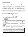
ITEM
1
DESCRIPTION
Lighted Display -- left display of various functions and operations.
2
Lighted Display -- right display of various functions and operations.
3
Program Lock and Temperature Check Switch -- locks program in
computer and/or displays frypot temperature when depressed. (Oldstyle computers will have this switch:
)
4/5
Power Switches— either switch turns power "ON" or "OFF". (Oldstyle computers will have this switch:
)
6/7
Product and Coding Switches – provides access to computer and
programming functions. (Old-style computers will have these
switches:
)
8
Programming Switch -- used when reprogramming the computer
)
memory. (Old-style computers will have this switch:
WARNING
Before turning on computer, ensure the fryer is filled with cooking oil/shortening or
water. NEVER allow water to enter the Filtration System (if applicable).
5–1
5.1 Operating Fryers with Dean Compu-Fry Computers (cont.)
5.1.1 Equipment Setup and Shutdown Procedures
Setup
WARNING
Fill the frypot to the bottom OIL LEVEL line with vegetable oil before pressing the
ON/OFF switch
to the "ON" position. Failure to do so could damage the frypot.
1. Fill the frypot with vegetable oil to the bottom OIL LEVEL line located on the rear of the frypot.
This will allow for oil expansion as heat is applied. Do not fill cold oil any higher than the
bottom line; overflow may occur as heat expands the oil. If solid shortening is used, pack solid
shortening into the cool-zone of the frypot. Continue to pack shortening in frypot to the bottom
OIL LEVEL line.
2. Ensure that the power cord(s) is/are plugged into the appropriate receptacle(s). Verify that the
face of the plug is flush with the outlet plate, with no portion of the prongs visible.
3. Ensure that the vegetable oil level is at the top OIL LEVEL line when the vegetable oil is at its
programmed cooking temperature. It may be necessary to add vegetable oil to bring the level up
to the proper mark, after the oil has reached the programmed cooking temperature. If solid
shortening is used, the MELT cycle MUST be used to melt the shortening. It may be necessary
to add solid shortening to bring the level up to the proper mark after the packed shortening has
melted. DO NOT DISABLE OR CANCEL THE MELT CYCLE UNTIL ALL SOLID
SHORTENING HAS MELTED.
Shutdown
1. Press the ON/OFF switch
to the "OFF" position (the display will show "OFF").
2. Filter vegetable oil (if applicable) and clean fryers. See Chapter 6.
3. Place the frypot covers on frypots.
Operating the Fryer
A. Turn the computer on by pressing the
switch.
1. One of the following displays will appear:
a.
, indicating that the burners are operating in the melt-cycle mode. Fryer will
remain in the melt-cycle mode until it reaches 180°F (82°C) or is canceled manually.
b.
, indicating that the pot temperature is 21°F (12°C) or higher than the setpoint.
c.
, indicating that the pot temperature is 21°F (12°C) or lower than the setpoint.
5–2
5.1.1 Equipment Setup and Shutdown Procedures (cont.)
" indicating that the fryer temperature is in the cooking range. NOTE: For best
d. "
results, do not cook product until the display reads "
".
e.
, indicates a heating problem.
f.
, indicates that the pot temperature is more than 410°F (210°C) [395°F (202°C) for
CE (European Community) fryers].
g.
, indicates that the computer has detected a problem in the temperature measuring
circuits, including probe.
NOTE: "." decimal point between digits 1 and 2 in either display area indicates that the burners are
on.
B. Melt-Cycle Cancel Feature (built-in computers only).
CAUTION
Do not cancel the melt cycle mode if using solid shortening.
The computer will display
during melt-cycle operation. To cancel melt cycle on a full pot,
depress the "R" button
. To cancel the melt cycle on a split pot, use the "L" button
for leftside pot and the "R" button
for right-side pot.
will be replaced by
. The decimal point
between digits 1 and 2 will illuminate indicating that the burners are on.
C. Cook-cycle operation is initiated by pressing the product switch:
1.
The basket lift (on fryers so equipped) will lower the product into the cooking oil/
shortening.
2.
The display will indicate the programmed cook time and begin countdown.
3.
If shake time is programmed, you will be notified to shake the product "X" seconds after the
cook cycle begins (X= amount of time programmed). An alarm will sound and the display
and the product number selected. If no shake time is programmed
will
will read
not appear during the cook cycle.
4.
At the end of cooking cycle, an alarm will sound;
will be displayed and the
associated product switch indicator will flash. To cancel the cook alarm, press the flashing
product switch.
5.
At this time, the hold time will be displayed (if programmed greater than 0) and countdown
will begin. When the hold time counter reaches 0, an alarm will sound.
and the
product number selected is displayed. The hold alarm is canceled by pushing the
switch.
If display is in use, hold time will count down invisibly until display is free.
5–3
5.1.2 Checking Temperature
A. Check the cooking oil/shortening temperature at any time by pressing the
Check the setpoint by pressing the
switch twice.
switch once.
B. During the idle periods, when the fryer is on but not in use, "
" should appear on both
displays on a single frypot computer. "
" will appear on the display of the side that is
turned on in a split-vat computer. If not, check actual temperature and setpoint.
C. If you suspect a defective probe, check the cooking oil/shortening temperature with a
thermometer. Verify that the computer readout is reasonably close to your measured reading.
NOTE: The electronic circuitry can be affected adversely by current fluctuations and electrical
storms. If for no apparent reason the computer does not function or program properly, reset the
computer by unplugging the power cord and plugging it back in.
5.2 Programming The Dean Compu-Fry Computer
1. Activate the computer by pressing either
switch.
2. To enter the program mode, first press the
switch.
will appear in the left display. If
you have pressed this switch in error and do not wish to program, press the
switch again.
if cooking is in progress.
Note: The computer will flash
3. Press
(1 6 5 0) in that sequence to enter the program mode.
4.
(Setpoint) will appear in the left display. This is for setting the cooking temperature. The
temperature previously selected will be displayed in the right display. Enter new temperature.
Press the
switch to lock in temperature setting. If the setting is correct, press the
switch to
cancel the selection.
5.
(Select Product) will appear in the left display. Press the product button to be
programmed.
6.
will appear in the left display. The sensitivity number previously selected will be
displayed in the right display. Enter the new desired sensitivity number, the range is 1 to 9.
switch to lock in the setting.
Enter "0" for no sensitivity. Press the
Sensitivity adjusts computer-cooking time to compensate for the drop in cooking oil/shortening
temperature when a basket of product is placed into the fryer. Sensitivity decreases or
increases cooking time to counterbalance variances in product density, basket-load size, and
initial temperature. A proper sensitivity setting will ensure a high quality product. For example:
4 ounces of fries can be programmed to cook to the same quality as 2 pounds. A good initial
setting is 4 or 5. Some experimenting with the range of 1 to 9 may be required to achieve
optimum quality.
5–4
5.2 Programming The Dean Compu-Fry Computer (cont.)
7.
will now appear in the left display. A previously entered cook-time will appear in the
right display. If that time is correct, press the
switch. If you wish to change the time, enter
the desired time in minutes and seconds. (The new time will be displayed in the left display.)
Press the
switch to lock in the setting.
8.
now appears in the left display. The previous shake time (if any) will appear in the right
display. If a product requires shaking during the cooking process, set the shake time by pressing
the number of minutes to cook before shaking. Press the
switch to lock in the time. If no
shake time is required, press "0" and press the
switch. Example: Total cook time 3:00
minutes, shake after cooking 1:00 minute.
At the end of 1:00 minute, a beeper will sound and the product button indicator will flash for
three seconds.
9.
will now appear in the left display. Set the time to hold the cooked product from 13
seconds to 60 minutes. Press the
switch. If you do not wish to use the hold time, enter "0"
and press the
switch.
10.
will appear in the left display. If you desire to program more products, return to Step 5.
If no more programming is required, lock in program by pressing the
switch.
11. "
" (Setpoint) will appear in the left display. This is for setting the cooking temperature.
The temperature previously selected will be displayed in the right display. Enter new
temperature. Press the
switch to lock in temperature setting. If you do not wish to change
the setting, press the
switch.
12. "
" (Select Product) will appear in the left display. Press the product button to be
programmed.
13.
will appear in the left display. The sensitivity number previously selected will be
displayed in the right display. Enter the new desired sensitivity number, the range is 1 to 9.
Enter "0" for no sensitivity. Press the
switch to lock in the setting.
Sensitivity adjusts computer-cooking time to compensate for the drop in cooking
oil/shortening temperature when a basket of product is placed into the fryer. Sensitivity
decreases or increases cooking time to counterbalance variances in product density,
basket-load size, and initial temperature. A proper sensitivity setting will ensure a high
quality product. For example: 4 ounces of french fries can be programmed to cook to
the same quality as 2 pounds. A good initial setting is 4 or 5. Some experimenting
with the range of 1 to 9 may be required to achieve optimum quality.
14.
will now appear in the left display. A previously entered cook-time will appear in the
right display. If that time is correct, press the
switch. If you wish to change the time, enter
the desired time in minutes and seconds. (The new time will be displayed in the left display.)
Press the
switch to lock in the setting.
5–5
5.2 Programming The Dean Compu-Fry Computer (cont.)
15.
now appears in the left display. The previous shake time (if any) will appear in the right
display. If a product requires shaking during the cooking process, set the shake time by pressing
the number of minutes to cook before shaking. Press the
switch to lock in the time. If no
shake time is required, press "0" and press the
switch. Example: Total cook time 3:00
minutes, shake after cooking 1:00 minute.
16. At the end of 1:00 minute, a beeper will sound and the product button indicator will flash for 3
seconds.
17.
will now appear in the left display. Set the time to hold the cooked product from 13
seconds to 60 minutes. Press the
switch. If you do not wish to use the hold time, enter "0"
and press the
switch.
18.
will appear in the left display. If you desire to program more products, return to Step 5.
If no more programming is required, lock in program by pressing the
switch.
5.2.1 Boil Feature
CAUTION
Do not drain water or boil-out solution into the filtration system (if applicable). Irreparable
damage will result and void the warranty.
1. Before switching the fryer "ON", close the frypot drain valve. Fill empty frypot with mixture of
cold water and detergent. Follow detergent instructions when mixing.
NOTE: Boil Mode will not turn on both sides of computer. Each side will have to be turned on
separately.
2. To program computer for Boil Feature, press either
3. Press the
switch.
switch.
will appear in the left display.
4. Enter
(1 6 5 3) in that sequence. The right display will read
. The
temperature is automatically set for 195°F (91°C). The fryer will attain this temperature and
remain there until either
switch is pressed, which cancels the boil-out mode. In high-altitude
locations, constantly monitor the fryer for over-boil conditions. If over-boil occurs, turn off fryer
immediately, allow to cool, and re-enter boil-out mode to continue the boil-out operation.
SEE CHAPTER 4.2 FOR ADDITIONAL BOIL-OUT PROCEDURES.
5–6
5.2.2 Fryer Recovery Time Check
1. To check recovery time, press the
2. Enter
displays for 5 seconds.
5.2.3
switch.
will appear in the left display.
(1 6 5 2) in that sequence. The recovery time will appear in both
Temperature Selection— Fahrenheit to Celsius (Not Applicable to Old-Style
Compu-Fry Computers)
1. To change the computer temperature from Fahrenheit to Celsius or Celsius to Fahrenheit, press
either
switch.
2. Press the
switch.
will appear in the left display.
(1 6 5 8) in that sequence. The computer will automatically convert the
3. Enter
temperature from Fahrenheit to Celsius or Celsius to Fahrenheit.
4. Press the
switch to display the temperature in the newly selected mode.
5.2.4 Constant Oil Temperature Display Mode (Not Applicable to Old-Style CompuFry Computers)
1. To program constant temperature display, press the
2. Press the
switch.
switch.
will appear in the left display.
3. Enter
(1 6 5 L) in that sequence. The cooking oil/shortening temperature will
display constantly in the right display on a full-pot and in both displays on a split-pot.
NOTE: During the product cooking process, the cooking time will not be displayed but timing will
be taking place.
4. To remove the constant oil-temperature display and display the cooking time, repeat Step 2 and
Step 3.
5–7
5.3 Operating Fryers with Thermatron Controllers
Fryer Power Switch: controls power to each
individual fryer, both in Thermatron or
Back-up mode.
POWER
O
F
F
Main Power Switch: connects/disconnects primary power; doublelighted with center position "OFF". This switch controls two
Thermatron controllers and/or two back-up thermostats.
O
N
B ON OFF ON
A
T
C
K
M
T
U
P MAIN POWER
O
F
F
O
N
O
N
O
F
F
O
F
F
BOIL OUT
O
F
F
Filter Power Switch: connects/
disconnects power to filter pump. Fryer
Power Switch should be "OFF" when
filter is in use.
POWER
O
N
BOIL OUT
B ON OFF ON
A
T
C
K
M
T
U
P MAIN POWER
O
N
FILTER
High-Limit Reset Switch: located under
each individual control panel. This
switch must be manually reset if fryer
exceeds high-limit setpoint.
Filter Reset Switch (7-Amp Circuit
Breaker): this switch is inline between
the filter pump and the Filter Power
Switch. Ensure Filter Power Switch is
"OFF" before resetting or replacing.
Boil-Out Switch: operates only in "Thermatron" mode. When
"ON", this switch bypasses the Thermatron melt-cycle and
allows the water temperature to reach 196°F.
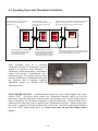
Many Decathlon fryers use a solid-state
temperature controller, or Thermatron® controller
instead of a computer or basic thermostat. A
Thermatron® system incorporates a temperaturecontrol circuit board, a potentiometer, and a
temperature probe. This system is more accurate
and more reliable than a standard thermostat, and
less expensive than a computer controller.
Thermatron systems are operated with the
Thermatron Temperature Controller
following controls:
MAIN POWER SWITCH – connects/disconnects primary power; double-lighted with center
position "OFF". One main switch controls two Thermatron controllers and/or two back-up
thermostats. When the Main Power Switch is in the center position, power is removed from the two
fryers controlled by the Thermatron controllers or back-up thermostats. When the Main Power
Switch pressed to the right, power is supplied to the Thermatron of each fryer. When pressed to the
left, power is supplied to the back-up thermostat of each fryer. The back-up thermostat should be
left in the "OFF" position when not in use (Newer fryers may not have the backup control
option).
5–8
5.3 Operating Fryers with Thermatron Controllers (cont.)
INDIVIDUAL FRYER POWER SWITCH – this switch controls power to the individual fryer,
whether the fryer is in the Thermatron mode or the back-up mode. When the power switch is in the
"ON" position, the indicator light will be lighted when calling for heat. The power switch only
removes power from the temperature control circuit (Thermatron and Back-Up Thermostat). The
power switch should be in the "OFF" position during filtering.
BOIL-OUT SWITCH – this only operates when in the Thermatron mode. When the Boil-Out
switch is "ON", it will bypass the Thermatron Melt Cycle, and allow the water temperature to reach
approximately 196°F.
FILTER POWER SWITCH (Optional) – controls power to the filter pump. Individual Power
Switch should be in "OFF" position when in use.
HIGH-LIMIT RESET – this reset button is located under each individual control panel, and must
be manually reset if the fryer exceeds high-limit setpoint.
FILTER RESET SWITCH (7 Amp Circuit Breaker) – the breaker is in line between the filter
switch and the pump. Turn filter power switch "OFF" prior to replacing.
5 AMP FUSE – each two fryer circuits are protected by a 5 amp fuse located under the 2nd and 4th
control panel.
5–9
DECATHLON SERIES GAS FRYERS
CHAPTER 6: PREVENTATIVE MAINTENANCE
6.1 General
Any equipment works better and lasts longer when maintained properly and kept clean. Cooking
equipment is no exception. Your Decathlon fryer should be kept clean during the working day, and
thoroughly cleaned at the end of each day. Below are recommendations for daily, weekly and
periodic preventative maintenance.
6.1.1 Daily
A. Remove and wash all removable parts.
B. Clean all exterior surfaces of the cabinet. Do not use cleaners, steel wool, or any other
abrasive material on stainless steel.
C. Filter the cooking oil and replace if necessary. The oil should be filtered more frequently
when under heavy use.
6.1.2 Weekly
A. Completely drain the oil from the fryer into a suitable container for disposal. Do not use a
glass or plastic container.
B. Clean the fry-vessel by following boil-out procedures in Chapter 4-2.
CAUTION
Never allow water to boil down and expose the heating tubes. Fry vessel damage
will result.
6.1.3 Periodic
The fryer should be inspected and adjusted periodically by qualified service personnel as part of a
regular kitchen maintenance program.
6-1
6.1.4 Stainless Steel Care
WARNING
DO NOT let water splash into the tank of hot oil. It will splatter and can cause severe
burns.
All stainless steel fryer cabinet parts should be wiped regularly with hot, soapy water during the day,
and with a liquid cleanser designed for stainless steel at the end of each day.
A. Do not use steel wool, abrasive cloths, cleansers or powders.
B. Do not use a metal knife, spatula or any other metal tool to scrape stainless steel! Scratches
are almost impossible to remove.
C. If it is necessary to scrape the stainless steel to remove any encrusted materials, soak the area
first to soften the deposit, then use a wood or nylon scraper only.
6-2
DECATHLON SERIES GAS FRYERS
CHAPTER 7: TROUBLESHOOTING
7.1 General
CAUTION
This appliance may have more than one power supply connection point. Disconnect
all power cords before servicing.
The problems and possible solutions covered are those most commonly encountered.
To troubleshoot, perform the test set-up at the beginning of each condition. Follow each step in
sequence.
WARNING
Inspection, testing, and repair of gas or electrical equipment should be performed by
qualified personnel.
Use EXTREME CARE when testing Live Electrical Circuits.
7.2 Pilot Burner Malfunction
A. Pilot will not ignite; no evidence of gas at pilot burner.
1. Check that gas valve is open and gas is present at the gas valve.
2. Check pilot burner orifice for dirt or lint.
3. Remove pilot burner gas-supply line and check for contamination; blow out if necessary,
then reinstall.
B. Pilot burner ignites but will not remain lit when gas valve manual knob is released.
1. Check that thermocouple lead is properly screwed into thermocouple connection bushing
on gas valve.
2. Remove end of thermocouple lead from thermocouple connection bushing and clean with
fine sandpaper or emery cloth.
3. Pilot flame may be too high or too low. Adjust pilot flame adjustment screw so that pilot
flame extends about ¾-inch (19-mm) above the top of the pilot burner.
4. Check all connections for cleanliness and security.
7-1
7.2 Pilot Burner Malfunction (cont.)
C. Pilot flame of proper size, but is unstable.
thermocouple completely at all times.
Flame wavers and does not envelop the
1. Check for drafts that might be caused by air conditioning equipment or make-up air
apparatus. Turn air-moving equipment off and recheck the pilot.
CAUTION
Do not attempt to turn the adjustment past the stops or the controller will be
damaged.
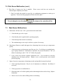
7.3
Main Burner Malfunctions
A. Main burner will not come “ON”; gas not detected at main burner.
1.
Check that the gas valve is open.
2.
Check that the pilot is ignited and is operating properly.
3.
Check the high limit switch for continuity.
4.
The combination gas valve may be defective; replace if necessary.
B. Main burner flames are small and appear lazy; shortening does not come up to temperature
quickly.
1.
Check gas pressure at the pressure tap of the gas valve. Use dial type or standard watertype U-gauge manometer. With burner in operation, the pressure should be 4" WC (10
mbar) for natural gas, and 11" WC (27.5 mbar) for propane.
2.
If not, remove the pressure regulator adjustment cover. Use screwdriver to turn the
adjusting screw for proper pressure. Replace cover, re-check pressure and re-install
pressure tap plug.
C. Signs of excessive temperature; shortening scorches and quickly becomes discolored.
1.
Check operating thermostat. May be out of adjustment or calibration. Recalibrate if
necessary.
2.
Check gas pressure as outlined above.
3.
Shortening used is of inferior quality and/or shortening has been used too long. Replace
shortening.
4.
Ensure vessel is clean when refilling with new shortening.
7-2
7.3
Main Burner Malfunctions (cont.)
D. Fryer will not reach the temperature setting and/or runs erratically.
1.
Incorrect location of sensor probe or defective temperature sensor.
2.
Loose wiring/wire connection
E. Fryer shortening temperature cannot be controlled; fryer runs at high-limit temperature.
1.
Defective operating thermostat or temperature probe.
2.
Call Service Technician.
7.4 Thermatron Calibration
The Thermatron controller maintains a specific oil/shortening temperature through a sensing probe
mounted in the fry vessel. If the actual temperature of the cooking oil varies from the controller dial
setting, loosen the knob setscrew and rotate the knob until it agrees with that of the actual oil
temperature. When obtaining actual oil temperature, ensure that the thermometer is inserted within
one-inch of the vessel-mounted probe. If proper calibration cannot be achieved, contact your service
agent for repair.
Thermatron Probe
Control Knob Setscrew (counter-set in knob)
7-3
7-4
TEMP
SENSOR
1
2
1
2
1 2 3 4
1 2 3 4
POT
1
2 3 4
1 2 3 4
GAS
VALVE
5
6
5 6
PV
MV
MV/PV
GND
IGN
TR
SEN
TH
OPTIONAL
BOIL OUT
SWITCH
C
1 2 3 4 5 6 7 8 9
14
3
7
8
9
10
11
12
TEMP
SENSOR
120 VAC "GO"
SOLID STATE
TEMPERATURE CONTROLLER
13
2
1
1 2 3 4 5 6 7 8 9
RELAY
R1
120 VAC
4
2
31
POWER SWITCH
1 2 3 4 5 6 7 8 9
IGNITION
MODULE
115 VAC
POWER
SUPPLY
1 2 3 4 5 6 7 8 9
SENSOR
IF INSTALLED,
BOIL-OUT CIRCUIT
WILL BE DUPLICATED
FOR BOTH THERMATRONS
BACK-UP
OPERATING
THERMOSTAT
115V
24V
IGNITOR
HI-LIMIT
THERMOSTAT
LEFT FRYER
1
2
1
2
1 2 3 4
1 2 3 4
POT
ON-OFF-0N
POWER SWITCH
1
14
3
7
8
9
10
11
12
120 VAC "GO"
SOLID STATE
TEMPERATURE CONTROLLER
13
2
1 2 3 4 5 6 7 8 9
1 2 3 4 5 6 7 8 9
RELAY
R2
120 VAC
5 AMP FUSE
24V
24V
GAS
VALVE
SENSOR
IGNITOR
IGNITION MODULE P/N 1906
24V
120 VAC
GAS
VALVE
PV
MV
MV/PV
GND
IGN
TR
SEN
TH
IGNITION
MODULE
MV
MV/PV
PV
GND
GAS
VALVE
(ALTERNATIVE - USED ON OLDER UNITS NO LONGER USED)
IGNITOR
115V
HI-LIMIT
THERMOSTAT
BACK-UP
OPERATING
THERMOSTAT
1 2 3 4 5 6 7 8 9
1 2 3 4 5 6 7 8 9
115V
4
2
31
POWER SWITCH
RIGHT FRYER
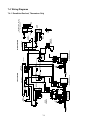
7.4 Wiring Diagrams
7.4.1 Decathlon Dual-vat, Thermatron Only
ORG
7-5
WHT
SENSOR
N. Open
Common
WHT
ORG
WHT
BLUE
BRN
WHT
Temperature
Sensor
1 2 3 4 5 6 7 8 9
V2D
L
PWR
J1 2
WHT
BLK
GRN
1 2 3 4 5 6 7 8 9
MV/PV
CND
PV
MV
SEN.
TH
IGN
TR
ORG
1
2
WHT
1
2
ORG
PURP
M
T
LED 2
L-HEAT
14
14
15
A
RL-1
6
6
J1
YEL
8
LED 1
L-GV
7
ON/OFF
POWER
2
2
1
1
LED 6
12V
3
3
3
12 VAC
5 1
115 VAC
BRN
RED
YEL
5
ON/OFF
POWER
5
AIR
LED 3
24V
R-GV
LED 5
8
7
YEL
115 VAC
J3
BRN
BRN
YEL
BRN
YEL
C.B.
A
4
4
RL-3
13
13
14
14
10
F1
M
T
2
LED 4
R-HEAT
11
11
4
J2
V1D
R
PWR
J3
SD
Sound
Device
Sound:
Terminal #1 - Loud
Terminal #2 - Medium
Terminal #3 - Low
1
2
1
2
Robertshaw
Thermostat
Back-up
V2D
PWR
RL1
RL2
J3
RL3
RL4
V1D
PWR
To Terminal Tab on
Computer
J1
(OR)
1
2
1
2
POT
SENSOR
PUR
YEL
ORG
BLK
WHT
IGNITOR
MV
MV/PV
PV
GND
Gas
Valve
RED
RED
IGN
TR
Gas
Valve
MV
MV/PV
CND
PV
SEN.
TH
120 VAC
13
2
14
3
7
8
9
10
11
12
1
BRN
WHT
1 2 3 4 5 6 7 8 9
WHT
BRN
BLUE
WHT
120VAC "G0"
Solid State
Temperature
Controller
Alternate Thermostat
1 2 3 4
1 2 3 4
24V
24V
HI TENSION
LEAD
24V
Alternate
Ignition Module
Ignition Module
HI TENSION
9-PIN Molex
Connector
Gas
Valve
RED
RED
IGNITOR
N.C.
9-PIN Molex
Connector
24V
C.
2-PIN
Connector-Amp
Temperature WHT
Sensor
BLK
115V
High-limit
Thermostat
4-PIN Molex
Connector
1 2 3 4 5 6 7 8 9
Common
Interface
Board
RL1 = 12VDC 2PST
RL2 = 12VDC SPST (NOT USED)
RL3 = 12VDC 2PST
RL4 = 12VDC SPST (NOT USED)
GRN
115V
Power Switch
SPST
1 2 3 4 5 6 7 8 9
N. Open
PURP
Pump
8GPM
Light
Right Fryer
ORG
ORG
Right Fryer
w/Cascade Filter
WHT
BLK
Motor
BRN
R2
C
NO
NC
PURP
BRN
Power Switch
SPST
Filter
Temperature
Sensor
5 Amp Fuse
1 2 3 4 5 6 7 8 9 10 11 12
Power Switch
SPDT
24 VAC Coil
24 VAC
PURP
WHT
1 2 3 4 5 6 7 8 9 10 11 12
YEL
R1
C
NO
NC
YEL
ORG
BRN
Power Switch
SPST
YEL
15
4
Left Fryer
Ignition Module
HI TENSION
ORG
9-PIN Molex
Connector
Gas
Valve
RED
RED
IGNITOR
WHT
ORG
Robertshaw
Thermostat
Back-up
24V
C.
ORG
Interface Board—
See Page 7-6 for enlarged view
115V
N.C.
GRN
Light
YEL
GRN
BRN
BLK
RED
High-limit
Thermostat
RED
WHT
WHT
Left Fryer
PURP
BRN
BRN
WHT
WHT
WHT
ORG
GRN
GRN
GRD
BRN
115V
WHT
Power Supply
GRN
115 V
BRN
Power Supply
ORG
YEL
PUR
GRN
BLK
WHT
GRD
BLUE
BLK
7.4.2 Decathlon Dual-vat, Computer Option
BRN
2
V2D
L
PWR
J1
7-6
M
T
L-HEAT
LED 2
14
14
15
15
4
LEFT
TEMP
PROBE
A
6
6
RL-1
LINE
VOLTAGE
8
C
2
3
ON/OFF
POWER
2
1
1
LED 6
1
LED 1
5
12V
7
12V
L-GV
R1
NC
NO
3
3
C
ON/OFF
POWER
5
5
AIR
LED 3
24V
R-GV
LED 5
8
24V
7
R2
NC
NO
A
4
4
RL-3
13
13
14
14
10
F1
M
T
11
11
R-HEAT
LED 4
HEAT
2
4
J3
J2
V1D
R
PWR
RIGHT
TEMP
PROBE
SD
Sound:
Terminal #1 - Loud
Terminal #2 - Medium
Terminal #3 - Low
Sound
Device
V2D RL2 RL4 V1D
J3
To Terminal Tab on
Computer
PWR RL1 RL3 PWR
J1
Interface
Board
RL1 = 12VDC 2PST
RL2 = 12VDC SPST (NOT USED)
RL3 = 12VDC 2PST
RL4 = 12VDC SPST (NOT USED)
7.4.3 Decathlon Interface Board (Enlarged View)
POWERSWITCH
220 VAC
POWER
SUPPLY
Temperature
Sensor
FUSE
2 AMP
1
2
1
2
24
VAC
7-7
12 34
12 34
POT
230
VAC
13
2
14
3
7
8
9
10
11
12
1
12 345 6 78 9
12 3456
48 OHM
RESISTOR
12 3456 78 9
24VAC
COIL
24VAC
COIL
HIGH-LIMIT
THERMOSTAT
24V "G0" SOLID STATE
TEMPERATURE CONTROLLER
DRAIN VALVE
SAFETY SWITCH
1 2 34 56
OPTIONAL BOILOUT
THERMOCOUPLE
SOLDER
CONNECTION
ECO
CONNECTOR
ASSEMBLY
G31 GAS
(LP GAS)
G20, G25 GAS
(NAT. GAS)
ELECTRODE
LEADWIRE
PIEZO IGNITOR
VALVE ADAPTOR
THREAD TO VALVE
GAS
VALVE
24 VAC
50 HZ
7.4.4 Decathlon D-50G and D-60G— CE Only
DECATHLON SERIES GAS FRYERS
CHAPTER 8: PARTS LIST
22
26
24
30
1
6
25
10
9
11
7
21
8
4
32
5
2
16
35
3
20
12
17
15
Controllers, probes and related/optional
components are listed in Optional
Components, Controllers and Related
Components, Section 8.5
18
31
19
13
24
34
27
28
14
29
33
8-1
8.1 Decathlon D-20 Primary Components
ITEM
1
*
*
*
2
3
*
*
*
4
*
*
*
5
6
7
8
9
10
11
12
*
*
*
*
*
13
14
15
16
17
18
19
*
20
21
22
23
24
25
26
27
28
29
30
PART #
07002-3
07002-4
07148-3
07148-4
07008
14-0067-6
14-0067-7
14-0067-10Blu
14-0067-2Red
07018-1
07018-2
14199-1CE
14199-2CE
14-0402
14154
2066
14-0001-1
N/A
14-0001-3
07-0044
2254
2729
1143
1910
2651
2652
07-0213
24-0350
44-0981-1
44-0981-2
07-0224
07-0132-2
2025
2674
07-0060
07001
07-0004
07141
2608
07011
07-0212
1943
1942
44-1363
24159
COMPONENT
Vessel Weld Assembly M/S
Vessel Weld Assembly S/S
Vessel Weld Assembly M/S (CE ONLY)
Vessel Weld Assembly S/S (CE ONLY)
Gas Manifold (Weld Assembly)
Orifice, Natural Gas
Orifice, LP Gas
Orifice, Nat. Gas G(20, 25) Blue (CE ONLY)
Orifice, LP Gas G(31, 37, 50) Red (CE ONLY)
Pilot Assembly For Natural Gas
Pilot Assembly For LP Gas
Pilot Assembly, Nat. Gas G(20, 25) (CE ONLY)
Pilot Assembly, LP Gas G(31, 37,50) (CE ONLY)
Manifold Support Bracket
Diffuser Assembly
Drain Valve
Burner, Left Side
Burner, Center
Burner, Right Side
Heat Shield
Gas Valve, Natural Gas, Electronic Ignition 24 VAC
Gas Valve, LP Gas, Electronic Ignition 24 VAC
Gas Valve, Natural Gas 120 VAC
Gas Valve, LP Gas 120 VAC
Gas Valve, Natural Gas G(20, 25) 24 VAC (CE ONLY)
Gas Valve, LP Gas G(31, 37, 50) 24 VAC (CE ONLY)
Channel
Lower Hinge Bracket
Side Panel, Left Side
Side Panel, Right Side
Wireway Control Panel
Control Panel
Switch, Rocker, Yellow Lens, 125/250VAC
Switch, Rocker, Green Lens, 125/250 VAC (CE ONLY)
Canopy
Flue Box Assembly
Vessel Upper Rear
Door Assembly
Fry Basket
Grid Assembly
Basket Hanger
Caster, 5-inch w/o Brake
Caster, 5-inch with Brake
Extended Drain Nipple
Power Cord
8-2
8.1 Decathlon D-20 Primary Components (cont.)
ITEM
31
32
*
*
33
34
35
PART #
11-0140-2
N/A
07-0139
07-0140
1731-2
14169
07-0006
COMPONENT
Cover, Outlet Duct
Rear Panel Structural Back
Upper Structural Back
Lower Structural Back
Leg (Black)
Leg Support Assembly
Burner Mounting Bracket
8.2 Decathlon D-50 Primary Components
ITEM
1
*
*
*
2
3
*
*
*
4
*
*
*
5
6
7
8
9
10
11
12
*
*
*
*
*
13
14
15
16
17
PART #
14907-1
14907-2
14948-1
14948-2
14130
14-0067-13
14-0067-2
14-0067-10Blu
14-0067-2Red
14199-1
14199-2
14199-1CE
14199-2CE
14-0402
14778
2066
14-0001-1
14-0001-2
14-0001-3
14-0590
2254
2729
1143
1910
2651
2652
36-0012
24-0350
50-0041-1
50-0041-2
50-0001-1
COMPONENT
Vessel Weld Assembly M/S
Vessel Weld Assembly S/S
Vessel Weld Assembly M/S (CE ONLY)
Vessel Weld Assembly S/S (CE ONLY)
Gas Manifold (Weld Assembly)
Orifice, Natural Gas
Orifice, LP Gas
Orifice, Nat. Gas G(20, 25) Blue (CE ONLY)
Orifice, LP Gas G(31, 37, 50) Red (CE ONLY)
Pilot Assembly For Natural Gas
Pilot Assembly For LP Gas
Pilot Assembly, Nat. Gas G(20, 25) (CE ONLY)
Pilot Assembly, LP Gas G(31, 37,50) (CE ONLY)
Manifold Support Bracket
Diffuser Assembly
Drain Valve
Burner, Left Side
Burner, Center
Burner, Right Side
Heat Shield
Gas Valve, Natural Gas, Electronic Ignition 24 VAC
Gas Valve, LP Gas, Electronic Ignition 24 VAC
Gas Valve, Natural Gas 120 VAC
Gas Valve, LP Gas 120 VAC
Gas Valve, Natural Gas G(20, 25) 24 VAC (CE ONLY)
Gas Valve, LP Gas G(31, 37, 50) 24 VAC (CE ONLY)
Channel
Lower Hinge Bracket
Side Panel, Left Side
Side Panel, Right Side
Wireway Control Panel
8-3
8.2 Decathlon D-50 Primary Components (cont.)
ITEM
18
19
*
20
21
22
23
24
25
26
27
28
29
30
31
32
*
*
33
34
35
PART #
50-0132
2025
2674
50-0127-1
12157
36005-2
50005
2608
14-0179
36-0026-2
1943
1942
44-1363
24159
11-0140-2
50-0050
N/A
N/A
1731-2
12085
14-0585
COMPONENT
Control Panel
Switch, Rocker, Yellow Lens, 125/250VAC
Switch, Rocker, Green Lens, 125/250 VAC (CE ONLY)
Canopy
Flue Box Assembly
Vessel Upper Rear
Door Assembly
Fry Basket
Grid Assembly
Basket Hanger
Caster, 5-inch w/o Brake
Caster, 5-inch with Brake
Extended Drain Nipple
Power Cord
Cover, Outlet Duct
Rear Panel Structural Back
Upper Structural Back
Lower Structural Back
Leg (Black)
Leg Support Assembly
Burner Mounting Bracket
8.3 Decathlon D-60 Primary Components
ITEM
1
*
*
*
2
3
*
*
*
4
*
*
*
5
6
7
8
PART #
60043-1
60043-2
60050-1
60050-2
18131
14-0067-1
14-0067-2
14-0067-10Blu
14-0067-2Red
14199-1
14199-2
14199-1CE
14199-2CE
14-0402
18063-1
2066
14-0001-1
COMPONENT
Vessel Weld Assembly M/S
Vessel Weld Assembly S/S
Vessel Weld Assembly M/S (CE ONLY)
Vessel Weld Assembly S/S (CE ONLY)
Gas Manifold (Weld Assembly)
Orifice, Natural Gas
Orifice, LP Gas
Orifice, Nat. Gas G(20, 25) Blue (CE ONLY)
Orifice, LP Gas G(31, 37, 50) Red (CE ONLY)
Pilot Assembly For Natural Gas
Pilot Assembly For LP Gas
Pilot Assembly, Nat. Gas G(20, 25) (CE ONLY)
Pilot Assembly, LP Gas G(31, 37,50) (CE ONLY)
Manifold Support Bracket
Diffuser Assembly
Drain Valve
Burner, Left Side
8-4
8.3 Decathlon D-60 Primary Components (cont.)
ITEM
9
10
11
12
*
*
*
*
*
13
14
15
16
17
18
19
*
20
21
22
23
24
25
26
27
28
29
30
31
32
*
*
33
34
35
PART #
14-0001-2
14-0001-3
60-0075
2254
2729
1143
1910
2651
2652
60-0007-1
24-0350
60-0021-1
60-0021-2
60-0001-1
60-0005-2
2025
2674
60-0006-1
18065
60044-2
60005
2609
18012-SC
18-0067
1943
1942
44-1363
24159
11-0140-2
N/A
60-0050
18-0023-1
1731-2
12085
18-0096
COMPONENT
Burner, Center
Burner, Right Side
Heat Shield
Gas Valve, Natural Gas, Electronic Ignition 24 VAC
Gas Valve, LP Gas, Electronic Ignition 24 VAC
Gas Valve, Natural Gas 120 VAC
Gas Valve, LP Gas 120 VAC
Gas Valve, Natural Gas G(20, 25) 24 VAC (CE ONLY)
Gas Valve, LP Gas G(31, 37, 50) 24 VAC (CE ONLY)
Channel
Lower Hinge Bracket
Side Panel, Left Side
Side Panel, Right Side
Wireway Control Panel
Control Panel
Switch, Rocker, Yellow Lens, 125/250VAC
Switch, Rocker, Green Lens, 125/250 VAC (CE ONLY)
Canopy
Flue Box Assembly
Vessel Upper Rear
Door Assembly
Fry Basket
Grid Assembly
Basket Hanger
Caster, 5-inch w/o Brake
Caster, 5-inch with Brake
Extended Drain Nipple
Power Cord
Cover, Outlet Duct
Rear Panel Structural Back
Upper Structural Back
Lower Structural Back
Leg (Black)
Leg Support Assembly
Burner Mounting Bracket
8-5
8.4 Decathlon D-80 Primary Components
ITEM
1
*
*
*
2
3
*
*
*
4
*
*
*
5
6
7
8
9
10
11
12
*
*
*
*
*
13
14
15
16
17
18
19
*
20
21
22
23
24
25
26
27
28
29
30
PART #
80018-1
80018-2
20092-1
20092-2
18131
14-0067-4
14-0067-5
14-0067-10Blu
14-0067-2Red
14199-1
14199-2
14199-1CE
14199-2CE
14-0402
20010-1
2066
14-0001-1
14-0001-2
14-0001-3
80-0069
2254
2729
1143
1910
2651
2652
20-0121
24-0350
80-0041-1
80-0041-2
80-0001-1
80-0005-2
2025
2674
80-0006-1
20053
80020-2
80005-1
2609
20000-SC
18-0067
1943
1942
44-1363
24159
COMPONENT
Vessel Weld Assembly M/S
Vessel Weld Assembly S/S
Vessel Weld Assembly M/S (CE ONLY)
Vessel Weld Assembly S/S (CE ONLY)
Gas Manifold (Weld Assembly)
Orifice, Natural Gas
Orifice, LP Gas
Orifice, Nat. Gas G(20, 25) Blue (CE ONLY)
Orifice, LP Gas G(31, 37, 50) Red (CE ONLY)
Pilot Assembly For Natural Gas
Pilot Assembly For LP Gas
Pilot Assembly, Nat. Gas G(20, 25) (CE ONLY)
Pilot Assembly, LP Gas G(31, 37,50) (CE ONLY)
Manifold Support Bracket
Diffuser Assembly
Drain Valve
Burner, Left Side
Burner, Center
Burner, Right Side
Heat Shield
Gas Valve, Natural Gas, Electronic Ignition 24 VAC
Gas Valve, LP Gas, Electronic Ignition 24 VAC
Gas Valve, Natural Gas 120 VAC
Gas Valve, LP Gas 120 VAC
Gas Valve, Natural Gas G(20, 25) 24 VAC (CE ONLY)
Gas Valve, LP Gas G(31, 37, 50) 24 VAC (CE ONLY)
Channel
Lower Hinge Bracket
Side Panel, Left Side
Side Panel, Right Side
Wireway Control Panel
Control Panel
Switch, Rocker, Yellow Lens, 125/250VAC
Switch, Rocker, Green Lens, 125/250 VAC (CE ONLY)
Canopy
Flue Box Assembly
Vessel Upper Rear
Door Assembly
Fry Basket
Grid Assembly
Basket Hanger
Caster, 5-inch w/o Brake
Caster, 5-inch with Brake
Extended Drain Nipple
Power Cord
8-6
8.4 Decathlon D-80 Primary Components (cont.)
ITEM
31
32
*
*
33
34
35
PART #
11-0140-2
80-0050
N/A
N/A
1731-2
12085
18-0072
COMPONENT
Cover, Outlet Duct
Rear Panel Structural Back
Upper Structural Back
Lower Structural Back
Leg (Black)
Leg Support Assembly
Burner Mounting Bracket
8.5 Optional Components, Controllers and Related Components (CE and
Domestic)*
* Components are applicable to all Decathlon Fryers covered in this manual unless otherwise noted.
1
2
3
9
8
12
13
4
5
10
11
14
17
18
6
16
15
19
20
21
8-7
7
8.5 Decathlon Component Options (CE and Domestic, cont.)
ITEM
1
2
*
3
4
*
*
*
5
*
*
*
6
7
8
*
*
*
9
10
11
12
*
13
14
15
*
16
*
*
*
17
18
*
*
19
*
*
*
20
21
* Not Illustrated
PART #
2557
1205
1205-1
2167
44907-1
44907-2
14199-1CE
14199-2CE
50-0004
50-0004
60-0004-2
20-0044-1
12148
2444
14702
18-0133
18142
1543
2560
2654
2650
14707
12147
12-0400
2723
227158
44-1128
1905
2518
2137
2658
(807-1999)
2687
1330
2747
1331
2445
2442
14701-2
2337-1
2517
2138
COMPONENT
Thermostat, Sunne
Knob, Thermostat (Domestic)
Knob, Thermostat (CE ONLY)
Spark Module (Domestic and CE)
Pilot Assembly For Natural Gas
Pilot Assembly For LP Gas
Pilot Assembly, Nat. Gas G(20,25) (CE ONLY)
Pilot Assembly, LP Gas G(31,37,50) (CE ONLY)
Control Panel, D-20
Control Panel, D-50
Control Panel, D-60
Control Panel, D-80
Bezel Assembly, Control Panel
Computer, Dean
“G0” Face Plate/Potentiometer/PC Board Assembly, 120 VAC
Face Plate, Thermatron
Potentiometer, Thermatron
Knob, Control- Thermatron
Electrode
Thermocouple
ECO Connector Assembly
Probe Assembly, Temperature-Thermatron ("G0")
Probe Assembly (RTD), Temperature, Dean Computer
Thermocouple Pilot Bracket
Thermopile Bracket
Piezo Ignitor
Piezo Bracket
Transformer Honeywell 120/24 VAC
Transformer 120/12 VAC
Transformer 120/24 VAC
Transformer, Dual CE (CE ONLY)
Thermostat, High-limit
Fuse Holder
Fuse Holder, Slot-head— Safety (CE ONLY)
Fuse 2A Slow Blow
Interface Board, Dean Computer Only
“G0” P.C. Board 24 VAC
“G0” P.C. Board 120 VAC
“G0” P.C. Board 208/240 VAC
Relay 12 VDC 1PDT
Relay 24 VAC 4PDT
8-8
Dean, 8700 Line Avenue, Shreveport, Louisiana 71135
TEL 1-318-865-1711
PRINTED IN THE UNITED STATES
FAX (Parts) 1-318-219-7140
SERVICE HOTLINE
1-800-551-8633
(Tech Support) 1-318-219-7135
Price: $8.00
819-5698 10-00