1
HAITILTO}I
RAI{GEMASTER
AM1OOO
AMt000
I
&
NSTALLATION I NSTRUCTIONS
-*:'t
OUTSIDE TRANSMITTER
AM 1000
213 CARAWAY LN
Cory NC 27 519
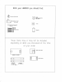
l#ith your AM1000 you should find:
6.
Sr.e
spore junper shunts
Q/
m
lloll tronsformer/
porer
12 voll
supply
tr
Tuning tool
q,
q*
@@
ffimrrX
€mtQ)
(6)
-Crystol
(unless you ordered lhc
ogile motule)
il
Eoits ooo nurs
Ferrite
Tronsmilter
-rt
'|
Inese rlems moy or moy not be Inclu0e0
I
t'
0epen0rng 0n whot you discussed 0I Ine tlme
of your order
'ttl
I
Frequency ogile modub
tflO0OPR ordio odopter
ffi
ffi
nn,.
H
,"lrTfiilit,n
H
Audio ottenuotor
tl
Instolling
the
AMl000 tronsmitter
unit is meont to be instolled by someone who hos some rodio bockground. lf you don't
feel quolified to instoll this unit yourself contoct o locol rodio/IV shop. They moy be oble to
help. Also if you hove o friend who is o Hom rodio operotor they moy be oble to help you.
The gool of <: successful instollqtion is to ochieve 1/z mile ronge if the unit is neor ground level.
Within this% mile the signol should be cleqrond eosy to heor. There moy be some stotic
mixed in, but the messoge being ployed should be cleor. Up to o mile ronge ond further moy
be possible if you hove o good site ond hove the unit higher. A good height is 30 feet.
Look oround the structure ond find o suitoble ploce to mount the tronsmitter. lt should be
mounted os high os possible. Keep in mind the cobling needs, o coble needs fo run to the
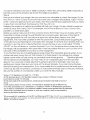
power ond oudio source. See included diogrom for cobling exomple. Typicolly #24 2 poir
,|00
shielded coble is used for runs of 50 feet or less, #22 for up to
feet. Use one poir for + ond
- l2 volt ond the other poir for the 600 ohm bolonced oudio. Connect the shield to ground ot
just one end. Also o ground wire needs to be run from the tronsmitter to o good ground for
lightning protection. You con drive o 4 or better B foot ground rod into the ground for the
lightning proiection ground or use on existing ground. For best lightning protection the
ground wire should hove o direct poth to dirt ground. lf you get low ronge ond the tuning
peok voltoge ronge is low you moy hove o bod ground. Driving qn 8 foot rod into soil should
insure you hove o good ground. An electricol or pipe ground moy not be relioble.
RF (rodio frequency) con be tricky stuff. lf you don't get results from your site, try onother. Ihe
height is very importont. The unit will not work unless it is tuned ofter it is instolled in its finol
position. (You con't iune it on the ground first, it HAS fo be tuned ofter everything is done,
wires tocked into position.
Avoid putting the ontenno neor metol, especiolly lorge mossive pieces of metol. Smoll metol
pieces moy be oll right. You wont to provide o stoble environment oround the unit. You con
chonge its environment by moving metol oround close by. Metol thot is connected to
ground hos o higher effect on the tronsmitter. Be sure to tell the customer or keep in mind if
you ore instolling it yourself thot if the tronsmitfer or ontenno or ground wire is moved, the unit
will not work conectly ond will need to be re-tuned. Attoch ony ground wire so thot it will not
move in the wind.
This
2
The qntenno develops hundreds of volts
of RF power. lf won't shock you ond con eosily be
quenched by even putting your hond close to it.
Once you've found o site sturdily mount the unit to the structure. Coble the ground wire to o
good ground. Use #12 or #.l0 wire or lorger (not oluminum) ond run the wire directly down to
your ground rod. The ground wire connects to the block binding post on the boitom of the
unit. lf your wire is to lorge to fit into the binding post use o short section of # l2 wire ond o wire
nut to complete the connection. Weotherproof the wire nut connection. lt is imporfont to
keep the ground wire owoy from metol on the woy to ground rod to get good ronge ond
provide the best lightning protection. Keep the ground wire owoy from other metol if of oll
possible. (See hints poge) A couple inches owoy is fine. Coble the unit to the inside to provide
power ond oudio for the tronsmitter. See included diogrom. The unit requires o 102" whip
ontenno thot con be purchosed of Rodio Shqck, Stock # 21-903. lt con be steel or fibergloss.
Some soy the fibergloss will give slightly better ronge. The striped wire is plus on included woll
power supply.
Begin the Tuning: You will need the following
Tuning tool (supplied)
VOM Meter
Medium Phillips screwdriver
Smo ll flotheod screwdriver
The VOM or volt ohm meter con be bought of o Rodio Shock. The onolog type or non digitol
is prefened. Be sure the crystol is insiolled if you ore not using the ogile module.
The crystolwill not lock into the boord, just seot it into the socket pins, it won't foll out.
Check thot "TUNE" is set 1/2woy between the counter- clockwlse position {Min.
Copocitonce) ond clockwise position (Mox. Copocitonce). Use the tuning tool to tune. When
"TUNE" is turned fully eitherwoy be coreful noi to opply to much force. Permonent domoge
moy result. "TUNE" will turn obout l0 turns. Moke sure thot the "Power Adjust" control is set to
obout 1/2 of the woy from counter clochryise. lt moy be o I turn or l0 turn control. Set
"AUDIO LEVEL" oll the woy down {counter- clockwise). lmportont Note: (TURN lT BACK UP
WHEN YOU ARE DONE TUNING!) (Ihis is o commonly missed item)
Set ihe "POWER SWITCH" to on. "Cobling note, you con use either terminol block for
cobling ihey ore both the some, {+ ond - is for power NOT S+ ond S-, AF+ ond AF- is oudio)"
Check oll of your cobling, turn the power on. You should be oble to see the power light come
on. See coble diogrom in this Monuol for cobling exomples. When using the Fenite if the hole
is to big iry to loop the coble through twice. The fenite instolls on the oudio coble just outside
the tronsmitter box.
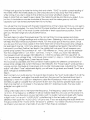
Slep 3
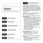
There ore 3 test hole pods on the unit (see diogrom). Toke o stondord voltmeter thot is set to
o low DC ronge (.|0 - 20 volts) ond plug it into the bottom ond top test hole pods. The block
leod will go to the test hole pod closest to the mounting hole (Ground).
Next move the jumper on the "COIL TUNE" jumper block one of o time to find the one thot
gives the highesf meter reoding or highesf power omp voltoge. Be sure thot only one jumper
is used of o time. Leove this jumper on the highest meter reoding ond proceed.lf you find 2
oreos of the jumper block thot give o peok reoding one of them moy be on hormonic. Chose
the position closest to the center of the jumper block ronge. lf you ore not seeing o good
meter reoding then rotote the PWR control until you do, or check your mefer.
Step 4
lf things look good so for toke the tuning iool ond rotoie "TUNE" to obtoin o peok reoding of
the meter. When the meter peoks you ore tuned. Be sure io stoy oway from the ontenno
while tuning. lf you ore to close to the ontenno your body will offect where it tunes.
Keep in mind thot you need fo see o peok. Ihe meter should rise ond foll os you odjust. lf you
just turn it clockwise or counter clockwise oll the woy ond the meter goes up until the
copocitor con't be turned onymore then it is not tuned.
You will get the most power with the leost copocitonce of the tuning cop thot you con get to
tune (counter clockwise). You moy find thot 2 jumper positions will tune. lf so use the one thot
tunes with the "TUNE" in the most counter clockwise or leosf cooqcifonce position. This will
give you the best ronge ond circuit performonce.
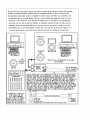
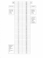
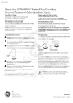
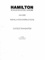
Step 5
The next step is to odjust the power level. This con be tricky for some people ond simply
involves toking 2 voltoge reodings ond multiplying them. (Refening to the chort in this monuol
will help) The result will be your power in Wotts. Turn the oudio pot oll the woy down. Once
you ore sure thot you hove o peok in the meter toke note of whot the power omp voltoge is.
For exomple ii moy be I Volt. Now ploce your Block {negotive) test leod in the bottom test
middle test hole pod. Ihis will meosure your
hole pod & your Red {Positive) test leod in the .l00
power omp cunent. The conversion is I volt =
milliomps or.1 Amp. Let's soy for exomple
thot the voltoge here is I volt. Then I volt times.l Amp =.1 Wott, you hove '100 milliwotts.
Your power should not exceed I 00 milliwotts or .l Wott to comply with FCC rules (Port I 5).
I volt powerompvoltoge times I volt poweromp cunent {..l Amp) =..| Wott or'100 milliwotts.
I X .l = .l Wott. Voltoge times Cunent equols Power.
This would be occeptoble. See the conversion toble supplied for different combinofions of
.l00
power omp voltoge ond cunent ihot equol
milliwotts. The "Power Adjust" works just like o
volume control. Clockwise is more power ond counter clockwise is less. Adjusting fhe "Power
odjust" will offect "Tune" odjustment slightly.you will wont to go bock ond tweok "Tune" for o
peok voltoge os detoiled eorlier.
Siep 6
Next connect your oudio source. lt is o good ideo to leove the "oud" oudio odjust % to oll the
woy up "clockwise" ond odjust the oudio level from the ground. The Terminol block input is
designed to work with o 600 ohm telephone coble like impedonce. When you order the
AMl000yougetonodopterihotwill convert Bohm (lowimp3.5mm) speokertypeoutputor
(high imp) like from o CD ployer to the required 600 ohm bolonced oudio. The new oudio
odopter hos o goin control.
Step 7
Using o test rodio tune to the tronsmitter frequency. The frequency used for this unit is often
I 5,l0 Khz . lf the frequency is different it will be morked inside the unit. Look on the crystol (Y1).
Once you pick up the signol on your test rodio, (with no oudio it will sound quiet with moybe
o slight hum. Turn up your "AUDIO LEVEL" while listening to the test rodio until you get
distortion then bock the "AUDIO LEVEL" off just o tod. lf you ore odjusting the oudio level from
the ground leqve the "AUDIO LEVEL" set obout % position. Your stotion should sound os loud
qs others in your areo on o test rodio, if you don't then there is o problem.
4
A scope is needed to be sure of 1AA% modulotion. When the unii is being rcA% moduloied o
test sine wove oi the ontenno will motch the originol woveform.
Step 8
Now go ond check your ronge. Use your cor ond your odometer to check the ronge. Do the
finoi tune on "TUNE" {Check to be sure the power amp volicge is still pecked}. Adjust "AUDIO
LEVEL" control for best sound on your rodio. Give the customer ony poperwork thot you need
to give ihem and tell them the frequency ihot the unit is on.
Keeping the ontenno os verticol os possible will help your ronge. lt is olso criticol to keep ihe
aniennc oway from metcl. Don't for exomple, rnount the antennc so it runs I /8 inch from"
pcrollel to o metol droin pipe.
Before you lecve moke sure ihct ihe cusiomer knows that if they have ony trouble wiih the
tronsmitter to simply unplug the woll tronsformer or power supply. Becsuse of ihe high RF
voltcge generoted the unit can induce o signol into phone lines" stereos, qnd other
equipment. The mosi ofien problem is with ihe phone line. Check their phone by getting rid
of the diql tone cnd listening for c recorded tesi messcge. lf ii is ihere ond i* borthers them you
could iry to put the unit in o site furiher from ony phone lines or you could odjust "POWER
ADJUST" on the unit down or counter clockwise" lf you tum the power down rnqke sure thot
the ronge is still occeptoble. With some sites ii moy be possible thot you con't put ihe unit in
beccuse of RF susceptible phone lines or other equipment.
lf you find ihoi you ore not getting good ronge check the tronsmiiter ground system, if you
notice thct when tuning ihe unii thot lnstecd of c shcrp peok in ihe volioge the voltcge
borely moves while you ore tuning you probobly hove o bod ground. Electricol grounds
will not clwcys be occeptqble. you may need to run o sepqrqte ground or find snother
ground. You could use o woter pipe thot is going to ground for exomple. Also if you ore
getting poor rsnge make sure yoL, hsve set the power propedy" lf you qre hoving troubles
recheck oll wiring ond connections. lf you hove conier but no oudio be sure the oudio pot is
tr rrnarl rvt/.rn Ro
ev
sure the power is connecied io the power terrninols cnd not the sync ierminals.
Be sure the crystol is in ond seoted {unless you hove fhe freq module).
Section 15.219 Operation in the band 510 - 1705 kHz.
(a) The total input power to the final radio frequency stage (exclusive of filament or heater
pon'er) shall not exceed 100 milliwails.
(b) The total length of the transmission line. antenna and ground lead (if used) shall not exceed
3
rnsters.
(c) All emissions belo*' 510 kHz or above 1705 UJIZ shall be attenuated at least 20 dB below the
level of the unmodulated carrier. Determination of compliance with the 20 dB atlrnuation specification
may be based on measurements at the intentional radiator's antenna output terminal unless the intentional
radiator uses a permanently atlached ant€nna, in which case comptiance shall be demonstrated by
measuring the radiated emissions.
*rth the FCC and following allFCC rules. The FCC is an independent governmenlal
agency, answerable only to congress, we cannot guarantee and/or we cannot be held responsible for what the FCC may do or
decide ln any particular situation.
We recommend fu111,'cooperating
{
POWER
ADJ UST
ILTON PCE DISICN
o
o
o
o
o
o
o
F
=
1-'
[Y
a
O
U
ON
I
/l
=
z
U1
oa
ft:
U
U1
-l
+l
*l
I
I
L
(,
Li-.]
Z
t:ra
o
o
o
o
o
o
TP,11
CND
-
,O O
o o--: oo
AO
"rrl'rif
rArj sLrLCr
SIttCI
COIL TAP
cDrL
b*l['"]:
- d='oo'-':;.1:i::il
ll
rrc
o
o
o
#o o
o
o
Q)*o-ro"or
!r'-9-:o-sgs;.
il :[i:!,trrit
o
q
4!
\VE
ili
flo
ct
R11
0
T,
R16 LtOr
+5V
O
O
o
COIL
,ur9*.;:
oo
TUNE
:4r._1.;;.rlo' oo o/ o
Bl l{" I ol . ]o ?] " l?J:-""
, cRl ---
t--
''VhS
Q't
-a/
o(7
',"o9;.
"/
o)/
o
/P /:r oo
\o o/
.'\ --l P
oFr fl El;-
LI
O.:
COIVP
8888
0
-
C'-)
L-Ll
L1
\o ")
OND
+
N-C
zt--\''
9TP1
^CO
RAt
o
CRYSTAL
6
,o-
u'Of
.-,,.
i-rsree!,,,
sor5
-t]
0
o
o
o
o
o
o
ru
6'r9_j--,,,.1
!bj-d,#,
"^/>14+.,
.,.rli c
C
"F
l[-!ffiiffii"i: *'-r'
ululgl iFffr'
l-l]
:" =i..O =,
O= O
"r
t
X
6
E.
UJP
---JGF
<=
<) <./)
_2.
usE MtN
50 FT 0R
#24
#22 AWc FOR 50-100
AWG
FoR
vE
=<
LJF
LESS
FT
=tL
oao
rlJ L!
!!O
ta
-J=
<=
f-v
(,/')
,
=6=
O
= ==
lio==i
o-o*ooE+-"^=
fo
o
P
=
39
xE
2 - a 5 od -e X<
-;
c-'
====6
><
(-)
RED=POS
mo
E
t!
F
.ul
=.
td
T
=
-lv
+JV
BLACK=NEG
PO!vIR
AUDIO
TERMINAL BLOCK
IN TRANSMITTTR
AUDIO
ADAPTER
470l50V0LT
II
._J rr[__Jrr
lN
l__________-
8
OuT
OHM BALANCED TO
600
OHM BALANCTD
ADAPTTR
ANOTHER SUITABLE 14_18VDC SOURCE MAY BE USED
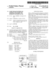
RANGTMASIER CABLE DIAGRAM
USE THIS CIRCUIT TO DRIVE
6OO BALANCED tryITH 8 OHM
SPEAKER OUTPUT
|vITHOUT ADAPTTR
of lor ronge is the oudio setup, even more common then grounding
power
(volume)
problem. Not enough oudio
ond/or on impedonce mismotch. lf you ore using on ohm
lYe hove found the most common csuse
I
(lor impedonce) output rhich rould be o heodphone or speoker output thot needs to be connected to the
lor impedonce input on the oudio odopter. Then the 2 screr terminol block needs to be wired vio 2 uire
tristed poir to the tronsmitter. lf you plug thc lor impedonce port of the odopter to o high impedonce
source like o line out jock you rill hove problems. An impedonce mismotch rill lorer the oudio level ond
reduce the fidelity, ond moy couse distortion. lf you hove o line out type source it needs to go to the
high impedonce jock on your oudio odopter. ln either cose
if
you con't get the oudio loud enough so
it is
os loud os other stotions in your oreo rithout distortion then there is o problem in the oudio choin.
SPEAKER OUT
/-.
tt JACK tl
\\ -//
\:7
HEADPHOI{E
OUT
rffi
v
THE AUIO()OPR UP TO
FULLY IIODULATE
-^.
/,. \\
II JACK II
\V/
\-/
HIGH
IIPEDANCE
THESE ARE ALL
Lon
|ilPEDANCE
(8-32 oHlr)
AUDIO SOURCES
SOURCES
EE::
STUDIO MIXER
[[[[[[[
ooooooo
ooooooo
ooooooo
ooooooo
3
J
auooolo E
AUI]IO
TWISTED EALANCED
- ADAPTER :=
g=
4
PAIR TO TRANSIIITTER
Crt
THE BALANCED PAIR TO THE TRANSITITTER IS SIITILAR TO YOUR TELEPHONE IYIRING.
THERE IS A POSITIVE AND I{EGATIVE WIRE, THE AUDIO IS THE DIFFERENCE BITWEEI{
THE THO f,IRES, THERE IS NO GROUND CONNECTION NEE[)ED. POLARITY DOESN'T
TIATTER Ui{LESS YOU ARE WIRING MULTIPLE TRANITSITTERS. SINCE THE TRANSIIITTER
LOOKS AT THT DIFFERENCE BETWEEI{ THE TIRES FOR THE AUDIO, NOISE TENDS TO
CANCELLED OUT. THAT IS flHY BALANCED AUOIO IS USED FOR LONG RUNS OF
WIRE. THE SHIELD IN THE r{IRE SHOULD BE GROUNDED AT O[.IE END OF THE CABLE
ONLY, YOU DON'T U{ANT CURRENTS FLOWIT{G IN THE SHIELD THAT TIAY INOUCE NOISE
O THE AUDIO, YOU CAN'T DIRECTLY DRIVE THE TRANSITITTTR IVITH ATIYTHING BUT
BALANCED 2 WIRE AU[)IO, A UIXER OR OTHER EQUIPilEI{T ]TAY HAVE AN XLR OR
TERITINAL SCREW BALANCEI} AUDIO OUT, IF IT DOES YOU CAN CONNECT OIRECTLY
TO THE TRANST4ITTER AS SHOilN.
EQUIPMENT TIAY OR UAY NOT
HAVE ENOUCH LINE OUT
LEVEL. IIIXER CONSOLES
YPICALLY TTILL HAVE ENOUGH
TUDIO OUT DRIVE. YOU NEED
TO BE SURE YOU ARE FULLY
TIHC THE TRANSIIIITTER
coraxtcT T0 THE
(IP) Ailo (frilc)
OF THE ILR
stEEvE ts THt cRouto
(N0 cot|lccTlor{ ETCEPT FoR
Y COI{ECT SHETD
AI
OIIE E]ID OF
lf you are using an Innovonics 222 be sure your output polarity is correct, here is how:
1. Turn the positive peaks all the way down
2. Turn the output level up until you get distortion, then back off a little (hair) for good sound.
3. Then turn the positive peaks all the way up, if you get distortion then the (output) terminals + and - are
probably reversed.
The polarity of the input terminals doesn't matter.
lf you are having trouble matching your input impedance to the lnnovonics see the website for instructions.
(How to hints, then audio button)
-Your station should sound as loud as others on the dial, if it doesn't there is a problem. lt may be an audio
impedance mismatch, or the level may need to be turned up. lf the audio level isn't high enough you won't get
good range, audio is a gate on the power, keep your audio turned up as high as you can.
-We have found the most common cause of low range is the audio setup, even more common then grounding
problems. Not enough audio power (volume) and/or an impedance mismatch. lf you are using an 8 ohm (low
impedance) output which would be a headphone or speaker output that needs to be connected to the low
impedance input on the audio adapter. Then the 2 screw terminal block needs to be wired via 2 wire twisted
pair to the transmitter. lf you plug the low impedance port of the adapter to a high impedance source like a line
out jack you will have problems. An impedance mismatch will lower the audio level and reduce the fidelity, and
may cause distortion. lf you have a line out type source it needs to go to the high impedance jack on your
audio adapter. In either case if you can't get the audio loud enough so it is as loud as other stations in your
area without distortion then there is a problem in the audio chain.
To get more Range:
Try to locate the transmitter near something that will reradiate the RF energy such as high tension power lines.
The signal will tend to follow lakes and rivers. Use as high a modulation level as you can. Get the unit as high
as you can but not so high you can't safely get to it to tune it.
Troubleshooting:
-Check the voltage at the terminals of the transmitter, is there at least 12VDC there?
-Low range is often a bad ground. There could be bad soil conductivity in your area, or the ground rod could
just be in gravel or sand instead of dirt. lf you can just push the rod in with your hand then it won't be a good
ground. Bad connections are often the problem. Just wrapping wire around a rod will NOT work. ALL
connections need to be soldered or clamped. The copper needs to be bright and shinny before soldering or
clamping. Be sure your ground wire is isolated and not wrapped around a metal mast or attached to metal
siding or downspout. The ground wire should be isolated from all massive (bigger then a nail) metal. Use an 8
foot ground rod if at all possible. lf you are using bigger then #12 wire (better) you won't be able to insert it into
the binding post at the transmitter. Use a short (6") piece of #12 as a splice make the connection. Twist the
#12vvrce to the larger wire and twist a wire nut on. Be sure to weatherproof this with some silicone. Then put
the other end into the ground binding post of the transmitter and tighten the binding post. lf you find that you
installation degrades after a few weeks you probably have a ground splice or connection that is weathering or
corroding somewhere. This ground wire must be locked down and stable so it won't move. Electrical grounds
will not always be acceptable, you may need to run a separate ground or find another ground. You could use a
water pipe that is going to ground for example. See the hints page for an example of a good ground system.
-Check quality of ground- After tuning unit, with the tune voltage at about 2-3 volts (rotate PWR) rotate the Cap
tune from the extreme counter clockwise position to the clockwise position while watching the meter. Make
note of the voltage swing you see, less then 1.5 volt, bad or no ground. 1.5-2 volts poor to adequate ground. 23 volts, good ground. 3-Svolts, great ground. This test will give you an idea where you stand with your ground
quali$.
-lf you are getting poor range be sure you are setting the power properly.
-lf you have carrier but no audio be sure the audio pot is turned up. Be sure the power is connected to the
power terminals and not the sync terminals.
-Be sure the crystal is in and seated (unless you have the freq module).
-ls power switch on?
-Are you using the tuning tool provided?
-When the transmitter is working properly it is possible to see a small spark with a pencil lead placed close to
the coil (large red round object) pins. You may need to turn the power up for it to do this. Or you may feel a
slight RF burn to your finger if you lightly touch the pins of the coil.
IF YOU AREN'I USING A IOTIER SIIIPLY
TOUIITIiIG THE TRAIISTITIER OVER A
GROUNDPLAIIE OR ELWATED GROUNDPLANE
|ILL HELP. THIS CAiI 8E AS SIIIPLE AS
IIISTALLITIG THE TRANSUITTER OVER A
EUILDIilG THAT HAS A YETAL ROOF.
DESICNING AN GROUIIOPLANE
COVERED
ELSETHERE OI{ THIS SITE.
THE TRAIISUITTER DOES REQUIRT
GOOD
GROUT{D TO OPERATE, IT CAN BE AS
SITIPLE AS USIiIC T}T EXISTING
ELECTRICAL GROUND OR VERY COIPLEX
AS SHEX USING I'ULTPLE GROUND RODS
AND BURIED RTDIALS.
EROUI{D RADIATS
AS IIANY AS PRACTICAL
.OROUIIDED
IS
TO TOIER
LENGTH
=
AT tErST
RAD FR0lt
A
T0ftR
= T0 AtlTENllA
HElGtlT
THE GROUIID RADIALS PROVIDE
A}I ELEVATED GROUNDPLANE
OR 'COUNTSRPOISE'
IF YOU TRY TO USE THE
TRAiISHITIER
-8nDNG
PoST
/'SEE
EXISTIIIG
ELECTRICAL GROUND OF A
BUIIDIIIo YOU IIAY NEED AiI ELECTRICIAN.
DETAIL A
ANY OROUiID YOU USE IIUST BE
ELECTRICALLY CONDUCTIVE.
FOR EXATPLE. IF YOU USE A IIETAT
ROOF CHECK IO SE SURE IT IS
ELECTRIALLY CONDUTIVE ACROSS
IT'S SURFACE.
GROUND
RADIALS
OI{E OF THE BEST TTAYS TO EET HORE RAI{GE TO TO TAKE ADVANTAGE OF THE
AIIIOOO'S ABILITY TO BE TIODULATEI) +I3OX. THERE ARE UANY AUDIO PROCESSORS
OII THE }TARKET THAT WILL DO THIS, THE CHEAPEST IS THE INNOVONICS 222.
SET INOVON.COTI THE OPTIIIOD IS ALSO A1{ EXCELLEI{T UHIT.
AI{OTHER TIP FOR GETTING GOOD RAI{GE IS TO OVER IIODULATE A 8IT.
Section
15.2'19
0perotion in the bond 510
-
1705 kHz.
of the
tronsmission line, qntenno ond ground leod
(if
used) sholl not exceed 3
meiers.
(c) All emissions belor 510 kHz or obove 1705 kHz sholl be ottenuoted ot leost 20 dB belor the
level of the unmoduloted corrier. Determinotion ol complionce rith the 20 dB ottenuotion specificotion
moy be bosed on mecsurements
of the intentionol rodiotor's ontenno output terminol unless
a
L.J
(9
ct
=
a
u1
lrl
a
=
o
(o) The totol input porer to the finol rodio frequency stoge (exclusive of filoment or beoter
porer) sholl not exceed 100 mitlirotts.
(U) ttre totot length
z,
o
the
intentionol
rodiotor uses o permonently ottoched ontenno, in rhich cose complionce sholl be demonstroted by
meosuring the rodioted emissions.
E
(9
a
lrl
o
a
Alroys cooperote rith the FCC ond follor FCC lor.
not pq!! !grn1q! the gqntlq on this poge (ex elevoted ground).
["!g ]t.l!! qql
ANOTHER TRICK IS TO KEEP II{ ITI}IO THAT ANY CONDUCTOR IN THE AIR THAT
ISN'T CROUNDED UILL CARRY YOUR SIGNAL. HIGH TENSION POYTER LINTS CAN CARRY
YOUR SIGIIAL FAR IF YOU CAI{ I}IOUCE YOUR SIGNAL II{TO THEII. EVEN YOUR
BACKYARO CLOTHESLINE CAN ACT AS A RADIATOR IF
IS ITETAL WIRE AIID
HAPPEI{S TO BE INSULATEI) AT THE TNDS. YOUR SIGNAL CAI{
BE PICKED
UP ATID RE-RADIATED.
KEEP THIS IN TIII{D & LOOK FOR CONDUCTORS LIKE THIS HHEN LOOKING FOR A
SITE FOR YOUR LOT POWER TRANSIIITTER.
IT
ANOTHER HINT
HEIGHT
BE
IT TO TUT{E IT
THAT
25-30
FEET IS USALLY GOOD FOR HEIGHT, UORE WILL GET IIORE
TIOST EANG FOR THE EUCK IS 25-30 FEET.
RANGE
TO GET GOOO RAI{GE:
ELEVATED GROUDPLANE
2- GET IT HIGH.
3- USE AN AUOIO PROCESSOR.
4- USE ISOLATED GROUND LEAO
5. ELEVATED OR BURIED RADIALS
o
UNIT
INSULATOR CAII BE CERAIIIC
0R AilY G000 sTR0[0 Noil-
8UT THE
COIIDUCTIVE IIATERIAL.
PLASTIC UOULD BE OK.
RANCEUASTER Tronsmitters
Drorn KFH
Dote 6/A4
Approv.
Scole
-t
trl
YOU CAN'T
PROPERLY.
IT'S ITIPORTANT THAT IT BE HICH, BUT IT'S CRITICAL THAT IT BE TUNED. THE
YJOI{'T WORK AT ALL IF IT'S NOT TUNED PROPERLY.
I-
=S
o
o
IS WATER. YOUR SIGNAL TILL CARRY UELL OVER OPEN HATER.
IS VERY IMPORTANT, BUT DON'T GET THI UNIT SO HIGH
GET TO
o
-G-
Size A
lt
I
Poge 1
of
'l
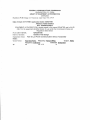
FEDERAL COMMUNICATIONS COMMISSION
WASHINGTON, D.C,24554
GRANT OF EQUIPMENT AUTHORIZATION
Certification
Hamilton PCB Design?l3 Caraway Lane Cary NC 27519
Date of Grant: A7fi7l19gg Application Dated: 05/08/1998
Attention: Keith Hamilton
NOT TRANSFERABLE
EQUIPMENT AUTHORIZATION is hereby issued to the named GRANTEE, and is VALID
ONLY for the equipment identified hereon for use under the Commission's Rules and
Regulations listed below.
FCC
IDENTIFIER:
Grantee:
NWXAMIOOO
Hamilton PCB Design
Equipment Class: Part l5 Low Power Communication Device Transmitter
Notes:
Output Wafts
Grant Notes FCG Rule Parts Frequency Ranqe (MHZ)
Emission Desiqnator
Frequency Tolerance
Name of
37
15
1.2 -
1.71
Yo
E
1.0
1.00
1.1
.910
.840
.770
.720
T.2
1.3
1.4
3.1
.670
.630
.590
.560
.530
.500
.480
.455
.435
.420
.400
.385
.370
.360
.345
.335
.325
aJ.L
aa
J.J
.305
1.5
t.6
t.7
BOTTOM
AND TOP
TEST
JACKS
1.8
t.9
2.0
2.7
2.2
L.J
')A
L.a
2.5
2.6
2.7
2.8
2.9
3.0
3.4
3.5
3.6
a-
3.8
3.9
4.0
4.1
A'
+.L
READINGS
NEEDED
THAT
PRODUCE
100
MILLIWAT
TS
.3 15
.295
.285
.280
.270
.265
.255
.250
.245
.240
+.3
,a
aaa
.LJJ
4.4
4.5
4.6
4.7
4.8
4.9
5.0
.228
.223
.218
5.1
.r97
5.2
5.3
5.4
5.5
5.6
5.7
.193
.189
.186
.183
.180
5.8
.174
.T7I
5.9
.2t3
.210
.205
.240
.r77
I
MIDDLE
AND BOT
TEST
JACKS
1.00
voLT
EQUALS
1OO
MILLI
AMPS
ACTUAL
CURRENT