1
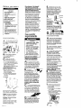
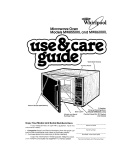
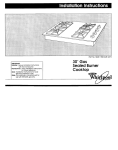
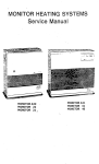
H
IMPORTANT
Installer:
Leave Installation
Instructions
with the homeowner.
Homeowner:
Keep Installation
Instructions
for future reference.
Save Installation Instructions for local
electrical
inspector’s use.
Part No. 3393 137 Rev. B
Before you start...
Fire Hozord
* Never install dryer up
ogoinst draperies or curtains
or on carpet.
- Keep any and all items from
falling or collecting behind
the dryer.
. Replace all access panels
before operating dryer.
Farlure to follow these
Mructions could result in a
‘ire or explosron.
. II you smell gas:
I. Open windows.
2. Don’t touch electrical switches
3. Extinguish any open flame.
4. lmmedialety call your gas
supplier.
. Do Not siore or use gasoline or
other flammable vopors and
tiauids in the vicinitv of this or
any other appliance.
The
lumes can create a lire hazard
or explosion.
Mark on X across the letter or
number OSyou complete each step.
A
You need these tools to install
. your Whirlpool gas dryer. Get
them together in one place to keep
track of them.
screwdriver
B
Check the spot where
. you’re aoina to install the
dfyer...‘proper~nstollotion
IS
your responsibility.
C
Make sure you hove
. everything necessary for
proper instollotion. You’ll need:
l
To meet code requiremenlr: some
codes keen from or limtt installation
of clothes dryers in garages,
closets, mobile homes and
sleeping quarters. (Check with Your
local building inspector,)
Important: Observe all governing
codes and ordinances.
. To check utilities: proper gas ond
electric supply connections
should be available.
l
To check exhaust requirements:
a four inch metal exhaust duct
is required.
Thii appliance is suiiable lor mobile
home Inslallalions. The inslallatlon
of Ihe &yer must contonn to the
Manuiachrred
Home Conshuclion and
Solely Slandard, Rle 24 CFR, Part 3280
(lormerly the Federal Standard tor
Mobile Home Construction and Wely.
Tile 24, HUD, Pati 280).
For mobile home use. this appliance
MUST be fastened to the floor and
MUST be exhausted to the outside.
Order Mobile Home Installation Kit
No. 346765 from your Whirlpool dealer.
Kit includes the necessary fastening
hordware and detailed installation
instructions. Exhaust system hardwore
is also available through your
Whirloool dealer.This installation must
conform with American National
Standard, Notional Fuel Gas Code
ANSI 2223.1 latest edition. and all
local codes and ordinances. Input
ratings shown on the rating plate
(serial tag) are for elevations up to
2.m) feet. For elevations above 2.ooO
feet. ratings should be reduced at a
rate of 4% for each 1.CJZUfeet above
sea level.
Gas supply
requirements
Fire Hazard
- This dryer must be connected to
a reaulated oas suoolv. Failure
to do so could cause highpressure gas release. resulting in
0 fire or explosion.
l
Have the L.P. gas checked by a
qualified person before instolling
the dryer. The L-P. gas supply
must not exceed 0 pressure of
13” water column,
. New flexible tubing should be
used. Reusing old tlexible
tubino miaht result I” oossible
leaks-or fire hazard.
Failure to follow these tnstructions
may result in fire or explosion.
OBSERVE ALL GOVERNING
CODES AND ORDINANCES
A
First make certain that this dryer
m is eauiooed with the correct
burner for the particular type of gas in
the home. Burner information will be
found on the rating plate in door well
of the opplionce.
If this information
does not agree wit the type of gas
available. see your dealer,
B
This dryer is
=equipped for
use with NATURAL GAS.
i
It is certified bv A.G.A.
for manufactured.
mixed ond L.P.
gases with appropriate
conversion,
No attempt shall be made to convert
the aDpliance from the aas SDeCKied
on therating plate for u& wrth a
different gas wtthouf consuiting the
serving gas supplier. ConversIon
musl be done by a qualiiied service
technician.
Gas converslon kit part
numbers are listed on the gas valve
burner base.
C
Size: Must be large enough to fully
open dryer door. For recessed or
closet installation spacing, see bock
cover.
Support: The floor must be able to
support the appliance weight of
175 pounds.
Level floor: Maximum floor slope
under dryer - 1 inch.
Protection from the weather: Proper
operation of dryer cycles requires
temperatures above 450 F.. or the
drver mov not shut off when
automatic cycles ore used
Panel
A
Provide a gas supply line to the
n dryer
location. When rigid pipe
is used it should be l/2 inch IPS. When
acceptable
to the gas supplier, 3/8
inch approved tubing may be used
for lengths under 20 feet. For lengths
over 20 feet. lorger tubing should be
used. Pipe joint COmDOundS
resistant
to the octidn of LP gas
D
The supply line should be
. equipped with a shutoff valve.
This valve should be located in the
some room as the dryer and should
be in a location that allows ease of
opening ond closing. Do not block
access to shutoff valve.
E
tf the dryer is installed in 0
. confined area such as a bed
room, bathroom or closet. it must be
exhausted to the outside and
provision made for enough air for
combustion and ventilation. (Check
governing codes and ordinances.)
Also refer to the section Of this
instruction covering Recessed or
Closet Installations.
F.
If local codes
oermit. R is
&ommended
that flexible metal
tubing.design
certiiied by the
American Gas
Association. be used for co
the appliance to the gas supply line.
Clhe gas pipe which extends through
the lower rear of the appliance has
3/8 inch male pipe thread.)
in-line connection
to the dryer.
H
Make sure that lower edges of
. the cabinet. plus the back and
bottom sides of the dlyer are free of
obstructions to permit adeauate
clearonce of air openings for
combustion air. See Recessed Area
Instructions. back page, for minimum
spacing requirements.
For ease of installation, operation
I n and servicing (if ever needed)
adequote space should be provided
around the dryer.
A l/8 inch NPT plugged tapping,
. accessible for test gauge
connection, must be ikrstalled
immediotely upstream of the gas
supply connection to the dryer.
The dryer and its individual shutoff
valve must be disconnected
from the
gos supply piping system during any
pressure testing of that system at
test pressures in excess of l/2 psig
(3.45 kPa).
The dryer must be isolated from the
gas supply piplng system by
closina its individual manual shutoff
vaiveduring
any pressure
testing of the gas supply piplng system
at test pressures equal to or
less that l/2 psig (3.45 kPa).
Important: Observe all govemlng
codesandordinances.
J
K
The dryer shutoff valve and the
. wiring diagram are located
behind the lower front access panel.
Open the access panel by pushing
down on the locklna CIIDSwith a small.
flat-blade screwdriver, and pulling
panel forward. The clips are located
on top of the panel 3 inches In from
each side. The aanel is hinaed at the
bottom. Close ihe access cane1 after
serviclng. Do Not operate the dryer
with the access panel open.
L
If drYer will not operate, check
. the following to be sure that
1. Electric supply is connected.
2. Fuse is intact and tight.
3. Door is closed.
4. Controls are set in 0 running or
*On %position
5. Start button has been pushed
firmly or the power control iever
moved upward to start.
6. Gas shutoff valves are open both
on drver and on SUDDIV lines.
Electrical
requirements
Eleclrrcol Shock Hazard
. Electrical ground is required on
this opptlance.
. Improper connection of the
equipment-groundrng
conductor co” result in a risk of
electrrcat shock.
. Check wrth o qualrlred
electrrcra” II you are r” doubt
OS to whether the opplrance IS
properly grounded. Do Nol
modify the power supply
cord ~Iua. If it will not fit the
outlei, h&e o proper outlet
installed by o qualrfied
electrician.
- Do Not use on extensron cord
wit thrs appliance.
Such use
may result rn a fire, electrrcol
shock or other personal injury.
. Do Not have a fuse in the
neutral or groundrng circuit. A
fuse in the neutral or grounding
circuit could result in electriical
shock.
Failure to follow these rnstructions
could result in electrical shock or
other personal injury.
A 12CFvolt. 60.Hz. AC only. 15or 20.
Amoere fused electrical SUDDIV IS
required. Time-delay fuse or circurt
breoker is recommended.
It is
recommended
that a separate
circuit sewing only this appliance
be provided
Recommended
grounding
method
Electncol ground is required on thus
appliance.
DO NOT. UNDER ANY
CIRCUMSTANCES, REMOVE THE POWER
SUPPLY CORD GROUNDING PRONG.
For your personal safety. thrs
appliance must be grounded. This
appliance is equipped wrth a power
supply cord having a 3-prong
groundrng plug.
To minimize possible
shock hazard. the
cord must be
plugged into a
matrng 3-prong
grounding-type
wall receptacle,
grounded rn
accordance
wrth
the Notronal
Electrical Code.
ANSI/NFPA 70 - latest
edition, and all local codes
and ordrnances. If a matrng wall
receptacle
is not avarlable. tt is the
personal responsibrlity and OblrQation
of the customer to hove a properly
grounded 3-prong wall receptacle
rnstalled by a quolrfied electrrcran
For added personal sotety. usrng the
Clamp and Qreen~colored copper
wrre furnished. connect this separo’e
groundrng wrre (# 10 mrnrmum) from
the external groundrng connector
on the back of the applrance to
o grounded cold water pope ’
DO NOT. UNDER ANY
CIRCUMSTANCES. REMOVE THE POWER
SUPPLY CORD GROUNDING PRONG
THIS. HOWEVER, IS NOT
RECOMMENDED.
It changrng and properly grounding
the wall receptacle ISrmpossible
Panel
B
and where local codes permit
(consult Your electrrcol Inspector). a
temporary adapter may be plugged
rnio the exrstrng 2-prong wall
receptacle to mote wrih the J-prong
power supply cord
It this ISdone. you must connect a
seporote copper grounding wire
(No.-18 mrnlmum) to a grounded cold
water pipe’ by meons of a clomp
and then to the external QrOUnd
connector screw
Do not ground lo a gas supply pipe
or hot water pipe. Do not connect to
electrrcal supply untrl appliance is
PermOnentlY QrOUnde
Use Duct Tape to seal all ~ornis
v
If the dryer is inslolled in a confined
area such OSa bedroom. bathroom or
closet. it must be exhausted to the
outstde and provrsion made for
enough air for combustron and
ventrlatron (Check governrng codes
and ordrnonces 1 Also refer to the
sectron of thus Instructron coverrng
Recessed and Closet lnstructrons
The Exhaust
Oullei is located
at the bottom ce
of the back dryer
Detorled space requrrements can be
found in the Recessed Area lnstructrons
on the back cover and on back panel
of dryer.
The Exhausl Duct
can be routed up.
down. left. rrght or
strarght out the
back of the dryer.
Frre/Heolth Hazard
Do Not use non-metal.
llexible duct.
Do Not use metal duct smatter
than four inches in diameter.
Do Not use exhaust hoods with
mognelrc latches.
Check that exhaust system is not
longer than specified. Exhaust
systems longer than specified
will:
-Accumulate lint.
Shorten the life of the dryer.
Reduce performance, resulling
in longer drying times and
increased energy usage.
oilure to follow specifications
nay resuli in o fire.
Do Not exhaust dryer into o
chimney. furnace cold air duct.
attic or crawl space, or any
other duct used for venting.
Clean the exhaust system every
other yeor.
Do Not instoll flexible duct in
enclosed walls, ceilings or floors.
6ccumulated lint could result in a
re or cause moisture damage.
- Exhaust the dryer outsrde to
prevent exposure to subslances
in the gas tuels and combustion
which may be harmful to your
health.
me moisture and lint indoors
may cause:
FIRE HAZARD tram lrnt
collected in dryer;
Moisture damage to
woodwork, furniture, paint.
wallpaper. carpel. etc.
- House cleaning problems and
Possible health problems
Failure to follow these instruchons
:ould result rn fire damage or
eersonol injury.
Met01 flexible duct may be used. It
should be fully extended and
supported when the dryer ISin Ifs trnal
postion DO NOT KINK OR CRUSH THE
DUCT The metal flexible duct must
be completely open to allow
adequate exhaust air to flow.
An Exhaust Hood should cap the
exhaust duel to prevent exhausted art
from returning into dryer The outlet of
the hood must be at least 12 Inches
from the ground or onylhing else that
may be in the path of the exhaust.
A 2-l/2 inch outlet Exhaust Haad
should be used with short systems
only. Crhis outlet creates greater back
pressure than other hood types.)
Exhausl Haads with magnetic tatches
should not be used.
The Maximum length of the exhaust
system depends upon the type of duct
used, number of elbows and type of
exhaust hood. The maximum length
for both riaid and flexible duct is shown
in chart -
For Exhausl Systems not covered by
the exhaust length chart. check
wrth your Whirlpool dealer or sewice
center for a dryer manual Port No
603197 The back pressure rn any
exhaust system used must not exceed
0.3 inches of water column measured
with an inclined manometer at the
point that the exhaust duct connects
to the dryer
For Mobile Home rnstalla
must have an outside ex
exhaust the dn/er
through the floor and
the area under Your
mobile home IS enclosed,
the exhaust system must
terminate outside the
enclosed area. Extension
beyond the enclosure wail
prevent lrnt and morsture
build-up under the
mobrle home.
Open the shutoff valve in the gas
supply line.
Frre Hazard
Do Not use on open flame lo IeSl
for leaks from gas connections.
Checking for leaks wrth a flame
may result in 0 fire or explosion.
Numbers
correspond
to steps.
11.
14
To exhaust
. the dryer.
see Exhaust
requirements.
Connect exhaust
duct to exhaust
&,
hood. Use duct
tape to seal all
joi&s in exhaust duct.
Y
Use caulking compound to
seal exterior wall opening around
exhaust hood
Now Start...
1
Tokitapeoff
fr0rt corners
of oryer
15
2
Open dryer and
.
remove the literature
and parts packages
(If dryer
has o drying rack rt should be
removed also.) Remove all parts from
the plastic packages. Line these up
next to your tools so each part
is there when you need it.
Check to see that YOU have
13
Use CI brush and liqurd
. detergent to test all gas
connections for leaks. Bubbles around
connections will indrcate a leak. If a
leak appears, shut off gas valve
controls and adjust connections.
Then check connecttons ogorn
A,
help Use a l’wrench or socket to finish
turning the legs until you reach the
diamond mark
Connect the grounding
wire to the external
grounding connector on the
back of the dryer. Connect
the other end of the
grounding wtre to o
grounded cold water pipe.
Plug the electrtcal cord into
n
16
7
ihe drum to
the cabinet
(Some dryer drums ore not toped for
shIpping 1 Move the drum by hand
to make certain all tape has been
removed Wipe the lnterlor of the
drum thoroughly v&h CI damp cloth
before usrng the dryer
Remove the tape from the IInt screen
. Now stand the dryer up
__ -e-c\
\
Move the dryer close to its final
‘a
i
locotron To make sure the drver
is level, take o carpenter’s level and
place it on the top of the dryer, first
side to side, then front to back If the
drver is not level. screw the leas of the
dr+er up or down to adjust. -
9.
Take two of the
cardboard corners from
the carton and place them
on the floor in bbck of the dryer
5
Firmly grasp the body of the
n dryer ond gently lay it on Its
back on the cardboard corners.
Remove the red cop from the the
gas pipe. Move the dryer into Its
final position.
10
Connect gas supply to dryer.
. Use pipe joint compound
resrstant to the action of LP gas for gas
connections
If flexible metal tubina
is used. be certoln there crre no kinks
6
With one of the
. legs in hand,
check the ridges for o
diamond marklng That’s
how for the leg is
supoosed to ao Into
the hole. Stortlto screw the legs
into the holes by hand A little ltqurd
detergent to lubrlcale the screw ~111
Panel
C
Inside the dryer is’4shopped In the “ON’ posItron. Check
that the gas valve shutoff control is still
in the “ON’ posItIon
Turn the
.dryer on to
remove air from the
gas supply line. Using 0
full heat cycle (not the
air cycle). let the dryer run for at
least five minutes. If the burner does
not ignite and you can feel no heat
inside the dryer. shut off the dryer for
five minutes. Check that all
supply valve controls ore in “ON’
position and that the electrical
cord is plugged in. Repeat the fiveminute test.
17 .
Check to see
that all of the parts
you removed from the
installatron parts packages in step 2
are now installed rn the dryer.
If you still have an extra part. go back
through the steps to see what
you skipped.
18
Check to make sure you
. have all the tools YOU started
wdh in step A.
Recessed
and closet
installation
instructions
If drver does
not dperate
*
properly...
If dryer will not operate,
check
following to be sure that:
Fire/Health Hazard
Exhaust the dryer to the outside
to prevent exposure to
substances in the gas fuels
and combustion
which may be
harmful to your hwlth.
l If dryer
is installed in a closet,
the dryer MUST be exhausted
outside.
Failure to do so may result in
a fire.
A.
B.
C.
D.
l
-he following installation spacings
‘2nd door air openings for the
:ompact
dryer are possible when
nstalled with or without the Stack
?ack Kit LCK 1100 and exhousted
JS noted. (Spacing as indicated
is
n inches and is minimum allowable
-or ease of installation and sewice,
additional spacing should be
:onsidered.)
Recessed
front view
the
?
Closet
Front view
*I 1tl-min
closet
Side view
TO PREVENT LARGE AMOUNTS OF
LINT AND MOISTURE FROM
ACCUMUlAllNG
AND TO MAINTAIN
DRYING EFFICIENCY, THIS MACHINE
MUST BE EXHAUSTED OUTDOORS.
’ Addhnal
cleorancer
tar wall. door and floor
moldw$
may be rs-wwx
“Opening
is minimum for closet door louvered
door w~,h eqwalent
cur openings LI occeptoble
“‘Add,hono,
space LSneeded when external exhaust
elbow IS used
Companion
appliance
spacings
should be considered.
Detalled space requirements
can
be found on the label located on
the back panel of dryer.
NOTE. No other fuel burning
appliQnce may be Installed in
the same closet
Electrical supply is connected.
Fuse is intact and tight.
Door is closed.
Controls are set in a running or
“ON’ position.
E. Start button has been pushed firmly
or the power control lever moved
upward to start.
F. Gas shutoff valves are open both on
dryer and on supply lines.
When moving the dryer...
l
Disconnect
the electrical
cord and
grounding wire and tape securely
to dryer.
l Shut off the gas supply
valve controls
in the gas supply line.
l
Disconnect
gas pipe fittings from
dryer and cap the gas supply line
l Tape
the drum to the front panel
Tape the dryer door, int screen lid
and end of gas pipe.
l
Screw leveling legs all the way in.
Before installing your dryer in your new
home, check with your gas supplier or
dealer to see that your dryer is
equipped
with the correct burner for
the particular type of gas in your new
home
Burner information
may be
found on the rating p’gte in the door
well of the dryer.