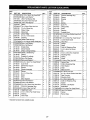
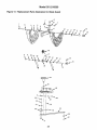
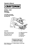
1
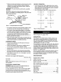
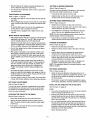
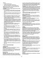
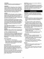
Operator's Manual
CRAFTSMAN
10"
CONTRACTOR TABLE SAW
Model No.
351.218330
CAUTION:
Read and follow all Safety
Rules and Operating
Instructions before First
Use of this Product. Keep
this Manual with Tool.
Sears, Roebuck
and Co., Hoffman
www, sears.com/craftsman
31105,00 Draft (07/01/09)
Estates, IL 60179 U.S.A.
Warranty .........................................
2
Safety Rules ....................................
Unpacking
Assembly
5
......................................
6-8
Installation ......................................
8-9
Operation .....................................
9-13
....................................
Repair Protection Agreement
Wear safety shoes with non-slip soles.
°
Wear safety glasses complying with United States ANSI
Z87.1. Everyday glasses have only impact resistant lenses. They are NOT safety glasses.
°
Wear face mask or dust mask if operation is dusty.
•
Be alert and think clearly. Never operate power tools when
tired, intoxicated or when taking medications that cause
drowsiness.
13
.......................
PREPARE WORK AREA FOR JOB
14
Troubleshooting ...............................
Parts Illustration and List ........................
16-17
18-29
Espafiol ......................................
30-47
•
Keep work area clean. Cluttered work areas invite accidents.
•
Do not use power toolsin dangerous environments. Do not
use powertools in damp or wet locations.Do not expose
power toolsto rain.
Work area should be properlylighted.
Keepvisitorsat a safe distancefrom work area.
•
°
ONE-YEAR FULL WARRANTY ON CRAFTSMAN
TOOL
•
if this Craftsman toolfails due to a defect in material or
workmanshipwithinone year from the date of pumhase,call
1-800-4-MY-HOME®TO ARRANGE FOR FREE REPAIR (or
replacementif repairprovesimpossible).
This warrantydoes not coverthe blade, whichis an
expendable part.
•
Keep childrenout of workplace.Make workshopchildproof.
Use padlocks,master switchesor removeswitch keysto
prevent any unintentionaluse of powertools.
Keep power cordsfrom comingin contactwith sharp
objects,oil, grease and hot surfaces.
TOOL SHOULD BE MAINTAINED
(fthis toolis everusedfor commercialor rentalpurposes,this
warrantywill applyfor only90 daysfrom the date of purchase.
This warrantygivesyou specific legal rightsand you may also
have other rightswhichvary from state to state.
Sears, Roebuck and Co., Hoffman Estates, IL 60179
WARNING:
For your own safety, read allof the instructions
and precautions before operating tool.
PROPOSITION
65 WARNING:
Some dust created by
power sanding, sawing, grinding, drilling and other construction activities contains chemicals known to the state of
California to cause cancer, birth defects or other reproductive
harm.
Some examples of these chemicals
Wear protective hair covering to contain long hair.
°
2-5
.......................................
Maintenance
•
•
•
Always unplugtoolpriorto inspection.
Consult manual for specificmaintainingand adjusting procedures.
•
Keep tool lubricated and clean for safest operation.
°
Remove adjusting tools. Form habit of checking to see that
adjusting tools are removed before switching machine on.
•
Keep all parts in working order. Check to determine that
the guard or other parts will operate properly and perform
their intended function.
°
Check for damaged parts. Check for alignment of moving
parts, binding, breakage, mounting and any other condition that may affect a tool's operation.
•
A guard or other part that is damaged should be properly
repaired or replaced. Do not perform makeshift repairs.
(Use parts list provided to order replacement parts.)
•
•
Maintain proper adjustment of rip fence and blade guard.
Never adjust saw while running. Disconnect power to avoid
accidental start-up.
are:
•
Lead from lead-based paints.
°
Have damaged or worn power cords replaced immediately.
•
Crystalline silica from bricks and cement and other
masonry products.
°
Keep blade sharp for efficient and safest operation.
•
Arsenic and chromium from chemically-treated
KNOW
lumber.
•
Your risk from these exposures vary, depending on how often
you do this type of work. To reduce your exposure to these
chemicals: work in a well ventilated area and work with
HOW TO USE TOOL
Use right tool for job. Do not force tool or attachment
a job for which it was not designed.
to do
•
Disconnect tool when changing blade.
approved safety equipment. Always wear OSHNNIOSH
approved, properly fitting face mask or respirator when using
such tools.
•
Avoid accidental start-up. Make sure that the tool is in the
"off" position before plugging in, turning on safety disconnect or activating breakers.
CAUTION: Always
°
Do not force tool. It will work most efficiently at the rate for
which it was designed.
•
Keep hands away from blade and moving parts and cutting
surfaces.
°
Never leave tool running unattended. Turn the power off
and do not leave tool until it comes to a complete stop.
•
Do not overreach. Keep proper footing and balance.
°
Never stand on tool. Serious injury could occur if tool is
tipped or if blade is unintentionally contacted.
follow proper operating procedures as
defined in this manual -- even if you are familiar with use of
this or similar tools. Remember that being careless for even a
fraction of a second can result in severe personal injury'.
BE PREPARED FOR JOB
• Wear proper apparel. Do not wear loose clothing, gloves,
neckties,rings, braceletsor otherjewelrywhichmay get
caught in movingparts of machine.
© Sears, Roebuck and Co.
2
•
Know your tool. Learn the tool's operation, application and
specific limitations.
°
•
Handle workpiece correctly. Press firmly against table.
Protect hands from possible injury.
Use extra caution when the guard assembly is removed for
resawing, dadoing, or rabbeting--replace
guard as soon
as that operation is completed.
•
•
Turn machine off if it jams. Blade jams when it digs too
deeply into workpiece. (Motor force keeps it stuck in the
work.)
Never turn the saw ON before clearing the table of all
tools, wood scraps, etc., except the workpiece and related
feed or support devices for the operation planned.
•
Never place your face or body in line with the cutting tool.
•
Feed work into the blade only as recommended
"Operation"
•
Never place your fingers or hands in path of saw blade or
other cutting tool.
•
For rip or rip-type cuts, the following end of a workpiece to
which a push stick or push board is applied must be
square (perpendicular to the fence) in order that feed
pressure applied to the workpiece by the push stick or
block does not cause the workpiece to come away from
the fence, and possibly cause a kickback.
•
During rip and rip-type cuts, workpiece must be herd down
on table and against fence with a push stick, push block,
or featherboards, as applicable (see Figures l a and lb,
page 4).
in
WARNING:
For your own safety, do not operate your saw until it
is completely assembled and installed according to instructions.
STABILITY OF SAW
If there is any tendencyfor the saw to tip over or move during
certain cuttingoperations,such as cuttingextremelyheavy
panels or long heavy boards, the saw shouldbe bolteddown.
If you attach any kind of extensionsover 24" wide to either
end of the saw, make sure you either bolt the saw to the floor,
as appropriate, or support the outerend ofthe extension from
the benchor floor, as appropriate.
The push stick and push block examples shown below are useful for keeping hands and fingers away from saw blade during
ripping, rabbeting and dadoing. Apply downward pressure and
push workpiece through the cut and past the blades. Several
other configurations may be suitable for safe operation.
LOCATION
The saw should be positioned so neither the operator nor a
casual observer is forced to stand in line with the saw blade.
Featherboards are used to keep the work in contact with the rip
fence or table during the cutting operation. Use of featherboards
can help to prevent kickbacks and binding. Featherboards
should be used for all "non thru-sawing" operations.
KICKBACKS
A kickback occurs during a rip-type operation when a part or
all of workpiece is thrown back violently toward operator.
Keep your face and body to one side of the saw blade, out of
line with a possible kickback.
•
Never reach in back of the cutting tool with either hand to
hold down or support the workpiece, remove wood scraps,
or for any other reason. Avoid awkward operations and
hand positions where a sudden slip could cause fingers or
hand to move into a saw blade or other cutting tool.
Kickbacks and possible injury from them can usually be avoided by:
• Maintaining rip fence parallel to saw blade.
•
Keeping saw blade sharp. Replace or sharpen anti-kickback pawls when points become dull.
•
Do not perform layout, assembly, or setup work on the
table while the cutting tool is rotating.
•
Keeping saw blade guard, spreader, and anti-kickback
pawls in place and operating properly. The spreader must
be in alignment with the saw blade and the pawls must
stop a kickback once it has started. Check their action
before ripping.
•
Do not perform any operation freehand--always
use either
rip fence or miter gauge to position and guide the work.
•
Never use the rip fence when cross-cutting or the miter gauge
when ripping. Do not use rip fence as a length stop. Never
hold onto or touch free-end of workpiece or a free-piece that
is cut off, while power is ON and/or saw blade is rotating.
•
Shut the saw OFF and disconnect power source when
removing the table insert, changing the cutting too],
removing or replacing the blade guard, or making adjustments.
°
Not ripping work that is twisted or warped or does not
have a straight edge to guide along the rip fence.
•
Not releasing work until you have pushed it all the way
past the saw blade.
•
Using a push stick for ripping widths less than 6 inches.
°
Not confining the cutoff piece when ripping or crosscutting.
Provide adequate support to the rear and sides of the saw
table for wide or long workpieces.
PROTECTION:
EYES, HANDS, FACE, BODY, EARS
• If any part of your saw is missing, malfunctioning,
or has
been damaged or broken (such as the motor switch, electronic controls, other operating control, a safety device or
power cord), cease operating immediately until the particular part is properly repaired or replaced.
•
Wear safety goggles that comply with United States ANSI
Z87.1 and a face shield or dust mask if operation is dusty.
Wear ear plugs or muffs during extended periods of operation.
Small loose pieces of wood or other objects that contact
the rear of the revolving blade can be thrown back at the
operator at excessive speed. This can usually be avoided
by keeping the guard and spreader in place for all thrusawing operations (sawing entirely thru work) and by
removing all loose pieces from the table with a long stick
of wood immediately after they are cut off.
3
ib
Plastic and composition materials (like hardboard) may be
cut on your saw. However, since these are usually quite
hard and slippery, the anti-kickback pawls may not stop a
kickback. Therefore, be especially attentive to following
proper setup and cutting procedures for ripping. Do not
stand, or permit anyone else to stand, in line with a potential kickback.
•
If you stall or jam the saw blade in the workpiece, turn saw
OFF and remove the workpiece from the saw blade.
Check to see if the saw blade is parallel to the miter
gauge grooves and if the spreader is in proper alignment
with the saw blade. If ripping at the time, check to see if
the rip fence is parallel with the saw blade. Readjust as
required.
•
Do not remove small pieces of cutoff material that may
become trapped inside the blade guard while the saw is
running. This could endanger your hands or cause kickback. Turn saw OFF and wait until blade stops.
Use extra care when ripping wood with twisted grain or
wood that is twisted or bowed--it may rock on table and
pinch saw blade.
4 It
5" Long (typ.)
Solid Lumber
%+" (typ.) J
"_•_,;,,,,
,,
+
IIIIIll}[IlUHIIilIlUlI"
I
¾,, J
Clamp to rip fence or
rip fence extension to
keep work on the
table.
12"
-
1½"
+
t
I Rip Fence
6½"
I
Table
,-- 13A,,
Blade
Miter slot
i
+
5 +1
!I_12"
'
i
I
I
.........
,I
+
I
I
p to table
to guide work
Use featherboards in combinations as required to control
workpieces.
Figure
lb - Featherboards
USE ONLY ACCESSORIES
•
Crosscutting operations are worked more conveniently and
with greater safety if an auxiliary wood facing is attached
to miter gauge using holes provided. However, facing must
not interfere with proper functioning of saw blade guard.
°
Make sure the top of the arbor or cutting tool rotates
toward you when standing in normal operating position.
Also make sure the cutting tool, blade flange and arbor
nut are installed properly. Keep the cutting tool as low as
possible for the operation being performed. Keep all
guards in place whenever possible.
•
Do not use any blade or other cutting tool marked for operating speed less than 4000 RPM. Never use a cutting tool
larger in diameter than diameter for which saw was
designed. For greatest safety and efficiency when ripping,
use maximum diameter blade for which saw is designed,
since under these conditions spreader is nearest the
blade.
2
Figure la - Push Sticks
and Push Blocks
KNOW YOUR CUTTING TOOLS
•
Dull, gummy, improperly sharpened or set cutting tools can
cause material to stick, jam, stall saw, or kickback at operator. Minimize potential injury by proper care and machine
maintenance.
WARNING:
Never attempt to free a stalled saw blade without first turning saw OFE
•
Never use grinding wheels, abrasive cutoff wheels, friction
wheels (metal slitting blades), wire wheels or buffing
wheels.
4
DESIGNED FOR SAW
•
Adjust table inserts flush with table top. Never operate saw
unless proper insert is installed.
M8 x 20 Hex Head Bolt (4)
M8 Lock Washer (20)
•
Never feed material into the cutting tool from the rear of
the saw. An accident and serious injury could result.
M8 Flat Washer (20)
M8 Hex Nut (16)
THINK
SAFETY
M8 Acorn Hex Nut (4)
Safety is a combination of operator common sense and alertness at all times when the saw is being used.
Never use another person as a substitute for a table extension, or as additional support for a workpiece that is longer or
wider than basic saw table, or to assist in feeding, supporting
or pulling the workpiece.
Hardware Bag #3
M6 x 16 Pan Head Screw (2)
Do not pull the workpiece through the saw blade--position
your body at the infeed side of the guard; start and complete
the cut from that same side. This will require added table support for long or wide workpieces that extend beyond the
length or width of the saw table.
MI0 x 25 Socket Head Bolt (4)
M8 x 16 Socket Pan Head Screw (8)
M6 Flat Washer (2)
M6 Hex Nut (2)
Hardware Bag #4
M6 x 12 Socket Pan Head Screw (24)
M6 x 16 Socket Head Bolt (2)
M5 x 12 Socket Head Bolt (4)
M3 x 10 Pan Head Screw (4)
CAUTION:
Follow safety instructions that appear on the front
of your saw.
M10 Lock Washer (4)
M6 Hex Nut (2)
M5 Lock Washer (4)
M3 Lock Washer (4)
M10 Flat Washer (4)
Refer to Figure 2.
CAUTION:
Do not attempt assembly if parts are missing.
Use this manual to order replacement parts.
Check for shipping damage or missing parts. If any parts are
damaged or missing, calt 1-800-266-9079 for replacement.
M6 Flat Washer (2)
M5 Flat Washer (4)
M3 Flat Washer (4)
The table saw body comes assembled as one unit. Additional
parts which need to be fastened to the saw should be located
and accounted for before assembling:
Hardware Bag #5
10/I3mm Open End Wrench
4mm Hex Wrench
A
B
Extension Tab]e (2)
Dust Chute
5mm Hex Wrench
8mm Hex Wrench
C
D
Front Rail (2)
Rear Rail (2)
E
F
G
Miter Gauge Assembly
Blade Guard Assembly
Dado Insert
H
Tab]e Insert
I
J
K
Handwheel Assembly with Knob (2)
Rip Fence Assembly
Rubber Foot (4)
E
_F
L
L Antkkickback Pawi Assembly
M Line Cord Hooks (2)
N Brace
O
Rip Fence Storage Hooks (2)
P
Q
R
Blade Guard Storage Hooks (2)
Push Stick Storage Hooks (2)
Push Stick
S
T
Base Panel (4)
Corner Support (4)
U
Caster Set (2)
Q
Hardware Bag #1
S
M!0 x 25 Socket Head Bolt (6)
M10 Lock Washer (6)
M10 Flat Washer (6)
a
L._
Hardware Bag #2
Figure 2 - Unpacking
M8 x 28 Hex Head Bolt (8)
M8 x 25 Hex Head Bolt (8)
5
P
IMPORTANT: Table is coated with a protectant. To ensure
proper fit and operation, remove coating. Coating is easily
removed with mild solvents, such as mineral spirits, and a soft
cloth. Avoid getting solution on paint or any of the rubber or
plastic parts. Solvents may deteriorate these finishes. Use
soap and water on paint, plastic or rubber components. After
cleaning, cover all exposed surfaces with a light coating of oil.
Paste wax is recommended for table top.
WARNING:
Never use highly volatile solvents. Non flammable solvents are recommended to avoid possible fire hazard.
°
Place the mobile base assembly onto the cabinet and dust
chute and secure in position with four socket head bolts,
lock washers and flat washers (Fig. 12, Key Nos. 10, 11
and 12).
NOTE: The foot pedals of the caster sets face towards front
and rear of cabinet, the push stick is attached to the left side
of the base and rip fence hooks are on the right side of the
base.
•
°
Press the four rubber feet (Fig. 12, Key No. 4) to the base
legs.
Turn the saw upright, reattach the back panel of the
cabinet.
HANDWHEEL
Refer to Figures 3, 4, 5, 7, 8, 9 and 10.
ASSEMBLY
Refer to Figure 13, page 26.
WARNING:
Make certain that the saw is disconnected
CAUTION: Do not attempt assembly if parts are missing.
Use this manual to order replacement parts.
from
the power source.
Be certain all parts are clean and free of shipping preservative. Also, completely remove all parts of packing. Saw cabinet
should be directly on the floor.
•
SAW INSTALLATION
°
Positioning the saw on a level surface (shimming may be
required) will improve stability and accuracy and prevent
warpage and failure of cast components and welds.
°
WARNING;
Make certain that the saw is disconnected from
the power source.
Place one of the handwheels (Key No. 30) onto the blade
raise/lower shaft (Key No. 56) located on the front of the
cabinet. Align the groove in the back of the handwheel
with the pin.
Thread the locking knob (Key No. 27) onto the threaded
end of the shaft.
Repeat the steps above to assemble the remaining handwheel and locking knob onto the bevel shaft located on
the right side of the cabinet.
ATTACH LINE CORD HOOKS
ASSEMBLE THE MOBILE BASE
Refer to Figure 10, page 20.
° Tilt the table to 45°.
Refer to Figure 12, page 24.
NOTE: Finger tighten bolts and nuts until assembly of mobile
base is complete. Then tighten all fasteners securely.
•
•
°
°
Use two M8 x 16 socket pan head bolts (Key No. 1) to
attach a corner support bracket (Key No. 3) to each fixed
support (Key Nos. 9 and 29) at the ends of one of the
caster sets.
Repeat for the other caster set.
Attach the front panel (Key No. 8 - stamped 'A') between
the two corner supports attached to one of the caster sets
using six M6 x I2 socket pan head bolts (Key No. 2).
Note: Place the panel edges INSIDE the corner support
surfaces.
ASSEMBLE
ASSEMBLE PUSH STICK STORAGE BRACKETS
Attach the rear panel (Key No. 8) between the two corner
supports attached to the remaining caster set.
= Attach the left side panel (Key No. 25 - stamped 'B') to the
assemblies made in the previous two steps.
• Attach the right side panel (Key No. 33 - stamped 'C') to
the assembly made in the previous step.
Refer to Figure 12, page 24.
Installthe push stickstorage brackets (KeyNo. 23) to the left
side panel (Key No. 25) of the base usingfour screws, lock
washers and flat washers (Key Nos. 20, 2t and 22).
ASSEMBLE
ASSEMBLE BASE TO CABINET
Refer to Figures i0 and 12, pages 20 and 24.
°
RIP FENCE STORAGE BRACKETS
Refer to Figure 12, page 24.
Install the rip fence storage brackets (Key No. 34) to the right
side panel (Key No. 33) of the base using two screws, flat
washers and hex nuts (Key Nos. 14, 31 and 32).
NOTE: Saw cabinet and base are very heavy. Two people are
required to assemble this saw.
•
°
BLADE GUARD STORAGE BRACKETS
Refer to Figure 12, page 24.
Installthe blade guard storage brackets (Key Nos. 18 and 19)
to the leftside pane[ (Key No. 25) of the base usingfour
screws, lock washers and fiat washers (Key Nos. 15, 16
and 17).
•
°
Install the line cord hooks(Key No. 9) using sockethead
bolts, washersand nuts (Key Nos. 10, 12 and 13) to the
leftside of the saw cabinet.
Place a large sheet of cardboard or carpet on the floor to
protect the table top.
Carefully place the saw cabinet upside down on the floor.
Remove the six bolts and the back panel (Fig. 10, Key
Nos. 2 and 24). This will allow you to adjust the cabinet
holes to align with the base holes.
Place the dust chute (Fig. 12, Key No. 30) on the cabinet
with the chute facing upwards.
ATTACH EXTENSION TABLES
Refer to Figure 11, page 22.
6
°
Assemble extension table (Key No. 35) to the table using
hex head bolts, lock washers and fiat washers (Key Nos.
36, 37 and 38).
°
Hand tighten only. Do not tighten completely until tables
are level.
°
Repeat above procedure for the other extension table.
•
Use a straight edge to check level and flatness between
main and extension tables.
•
After tables are adjusted level and flat, secure the extension tables by tightening the hex nuts completely.
RAIL ASSEMBLY
Refer to Figure 11, page 22.
° Insert two M8 x 28 hex head bolts and two M8 x 25 hex
head bolts into the T-slot of the right front guide rail (Key
Nos. 16, 21, and 22) (The two longer bolts will attach to
the table; the two shorter bolts attach to the table
extension.)
CHECK TABLE ALIGNMENT
Refer to Figures 3 and 13, pages 7 and 26.
•
Saws are shipped from the factory with the table adjusted
so the miter gauge slots are parallel to the saw blade.
However, in order to obtain the best results from the saw, it
is suggested this adjustment be checked before operating.
°
A simple method of checking alignment is as follows: Bolt
or clamp a dowel rod or similar object to miter gauge (a
combination square can be substituted). Pick out a tooth
on front of blade and set the dowel to it so it is just touching. Move same tooth to back of blade.
•
•
NOTE: Hand tighten all hardware during rail assembly. Do not
completely tighten hardware until all rails are mounted.
Gauge this tooth with the dowel rod. If the tooth is in the
same position, relative to the miter gauge, the table is parallel with the blade. In short, the miter gauge slots must be
parallel with the blade. This means that when measuring
distance between blade and slot at the front and rear of
the blade, the distances will be equal (see Figure 3).
•
Attach the left front rail and both rear rails (Key Nos. 18, 32
and 34) in the same manner.
•
Position rails so that rails are butted together and the joint
between rails is aligned with the blade.
Secure all hardware completely.
Use a straight edge to check level and flatness between
right and left rail and make certain that both front rails are
parallel to the table surface.
•
•
•
NOTE: Be positive to measure the distance or make the test
on the same tooth of the saw blade in both front and rear
positions.
•
•
•
If an adjustment is necessary, proceed as follows: (Refer
to Figure 13). Loosen the hex head bolts and lock washers (Nos. 36, 37 and 38) of the trunnion. Shift trunnion
until a position is found where the saw blade is parallel to
the miter gauge slots.
NOTE: Saw blade should also be centered within its table
insert opening.
,
After front rails are adjusted level and flat, tighten the
screws completely.
Repeat above steps for rear rails.
Attach the brace (Key No. 30) to the far right end of the
rails using four hex head bolts, flat washers, lock washers
and cap nuts (Key Nos. 26-29).
ATTACH
SWITCH
ASSEMBLY
Refer to Figure 11, page 22.
•
Rear
r_Y
Attach rail to the table and right table extension using flat
washers, lock washers and hex nuts (Key Nos. 23, 24 and
25).
Attach the switch assembly (Key Nos. 1-10) to the bottom of
the left side of the front rail using two flat washers, lockwashers and hex head bolts. (Key Nos. 11, 12, 13 and 14).
RIVING
KNIFE
ASSEMBLY
__'1",j_,
Refer to Figure 4, page 8.
WARNING:
Make certain that the saw is disconnected from
the power source.
:
_aw
_Blade :
t
I
1
Ii
•
•
Ii
I
i
Ii
1
1
Ii
Ii
•
•
Riving knife must be in line with blade. Make sure riving
knife sits flat against mounting bracket and lock plate.
RIVING KNIFE TO BLADE ADJUSTMENT
Refer to Figure 4, page 8.
Front
•
"'Miter Gauge Slots ''f
Figure 3 - Aligning Miter Slots to Blade
•
°
Riving knife is installed on the saw. Raise the blade completely to access the riving knife.
Loosen the locking knob and raise the riving knife to its
highest position. Riving knife has three holes for three positions. The highest position is for all thru cuts. The middle
position is for rabbets and other non-thru cuts, (with guard
and pawls removed). The lowest position is for dado cuts.
Make sure locking pin is aligned with riving knife hole and
secure in position by tightening locking knob.
Tighten the hex head bolts and lock washers very securely.
This procedure will set the table and blade in parallel position and prevent the trunnion from shifting.
Riving knifeto blade cJearance:the gap between the riving
knife and the saw blade should be an even distance
across the entire radius.
The rivingknifeshouldalso be in line with the saw blade, if
adjustmentis necessary:
1. Locatethe riving knife bracket.
2. Loosenthe two sockethead cap screws slightlyenough
to move the bracketbringing the rivingknife in linewith
the saw blade makingsure the gap between the blade
and knifeis even and from ¼to _," in distance,
3. Once the riving knife is alignedwiththe blade, tighten
the socket head cap screws.
7
RIP FENCE ASSEMBLY INSTALLATION
Refer to Figure 9, page 18.
° Positionrip fence assembly at end of saw. Be certainlocking lever (Key No.2) is in UP unlockedposition.
° Place rip fence assembly onto rails,positioningclamp (No.
26) over rear rail and then placingripfence ontofront
guide rail.
° Rip fence should now ride freely on rip fence rails. Once
rip fence is completely installed, it should be thoroughly
adjusted. (See Operation, page 11, Rip Fence
Adjustment.)
Locking
Pin
INSTALL MITER GAUGE
Refer to Figure 14, page 28.
°
Figure 4 - Riving Knife
°
INSTALL TABLE INSERT
Refer to Figure 11, page 22.
° Place table insert (Key No. 41) into throat of table.
• Insert is held in position by magnet in table.
•
To adjust insert level with table, adjust leveling screws (Key
No. 42) up or down.
ATTACH BLADE GUARD AND ANTI-KICKBACK
PAWLS
Placethe slot of blade guard body (Key No. 11) over the
riving knife.Throughbolt of guard is placed in the notch
indicatedin Figure5.
•
Positionguard completelydownon rivingknifeand press
latch (Key No. 16) to lock in position.
°
Bladeguard body should be parallel to the table.Use set
screws(Key No. 8) to adjustif needed.
•
Place anti-kickbackpawl set onto rivingknifeat notches
indicated.The springpin is placedin the front notchand
bolt is placed in the rear notch.
°
Press pawl set completelydown and press latchto secure
in position.
ELECTRICAL
CONNECTIONS
GROUNDING
INSTRUCTIONS
WARNING: improperconnectionof equipmentgrounding conductorcan resultin the riskofelectricalshock.Equipmentshould
be grounded whilein usetoprotectoperatorfrom electricalshock.
• Check with a qualifiedelectrician if groundinginstructions
are not understoodor if in doubtas to whetherthe tool is
properlygrounded.
• Thistool isequippedwith an approved3-conductorcord
rated at 300V and a 3-pronggroundingtypeplug(see Figure
6) for yourprotectionagainst shock hazards.
Refer to Figures 5 and 14, page 28.
•
•
Grounding plug should be pluggeddirectlyintoa properly
installedand grounded3-prong grounding-typereceptacle,
as shown (Figure6).
Properly Grounded Outlet
NOTE: The teeth of anti-kickback pawls should touchtable
surface. Use set screws (Key No. 17) to adjust if needed.
iBlade Guard
The mitergauge comespreassembled.Unpackthe miter
gauge and clean thoroughly.Be certain mitergauge
T-slotsin table are also thoroughlycleaned.
The mitergauge is guidedthroughthe T-slotwith a roller
guide at the frontof guidebar. To insertmiter gauge, first
insert rollerguideintoT-slotat front of table.
Grounding
Pawl Set
Prong
3-Prong Plug ___
Figure 6 - 3-Prong Receptacle
°
Do not remove or alter grounding prong in any manner. In
the event of a malfunction or breakdown, grounding provides a path of least resistance for electrical shock.
WARNING:
Do not permit fingers to touch the terminals of
plug when installing or removing from outlet.
8
•
Plug must be plugged into matching outlet that is properly
installed and grounded in accordance with all local codes and
ordinances. Do not modify plug provided. If it will not fit in
outlet, have proper outlet installed by a qualified electrician.
°
Inspect tool cords periodically and if damaged, have them
repaired by an authorized service facility.
•
Green (or green and yellow) conductor in cord is the
grounding wire. If repair or replacement of the electric cord
or plug is necessary, do not connect the green (or green
and yellow) wire to a live terminal.
Where a 2-prong wall receptacle is encountered, it must be
replaced with a properly grounded 3-prong receptacle
installed in accordance with National Electric Code and
local codes and ordinances.
WARNING:
electrician.
240 VOLT OPERATION
°
To use the saw with a 240V, single-phase power supply,
have a qualified electrician attach a 240 volt, 15A 3-prong
plug onto saw line cord and install the proper connectors
and receptacles to power supply.
•
See wiring diagram (Figure 8) for wiring instructions.
This work should be performed by a qualified
A temporary 3-prong to 2-prong grounding adapter (see
Figure 7) is available for connecting plugs to a two pole outlet
if it is properly grounded.
Grounding Lug
Adapter
3-Prong Plug
°
°
Make Sure
This Is
Connected To
°
)
1
)
(.
4
)
(..
3
(
1
•
Use the table to determine the minimum wire size (A.W.G.)
extension cord.
°
Use only 3-wire extension cords having 3-prong grounding
type plugs and 3-pole receptacles which accept the tool plug.
•
If the extension cord is worn, cut, or damaged in any way,
replace it immediately.
L2
(
240V
2
)
4
)
L2
DESCRIPTION
The Craftsman 10" Model Number 218330 contractor saw
offers precise cutting performance for all woods up to 3_"
thick. The saw is designed for the professional user and is
ruggedly constructed for continuous service. The 10" Saw is
recommended for use with a 10" blade.
The use of any extension cord will cause some drop in
voltage and loss of power.
Wires of the extension cord must be of sufficient size to
carry the current and maintain adequate voltage.
)
L
Refer to Figures 9-14, pages 18-28.
CORDS
°
1
120V
I
Figure 8 -Wiring Schematic
Many cover plate screws, water pipes and outlet boxes are
not properly grounded. To ensure proper ground, grounding
means must be tested by a qualified electrician.
The saw features an extra large cast iron table. Saw body has
on board storage for push stick, miter gauge, rip fence and
saw blades. Saw is equipped with a riving knife and a clear
acrylic blade guard with anti-kickback feature. Cabinet is constructed of heavy gauge welded steel, totally enclosed and is
ported for a 4" vacuum hose.
Rip Fence Assembly features a heavy-duty precision rip fence
that is designed for simple and one-hand maneuverability.
Front rail is calibrated in inches and millimeters with a magnified window for close tolerances.
SPECIFICATIONS
Cord Length (120V Operation)
Wire Size A.W.G.
Up to 25 ff.......................................
14
Up to 50 ft.......................................
12
Capacity with 10" Blade:
Depth of cut at 90 °. ..............................
Maximum tilt angle of arbor (left) ....................
Depth of cut at 45 ° . .............................
NOTE: Using extension cords over 50 ft. long is not
recommended.
ELECTRICAL
2
kl
(A 3-prong to 2-prong grounding adapter is not permitted
in Canada.) Where permitted, the rigid green tab or terminal on the side of the adapter must be securely connected
to a permanent electrical ground such as a properly
grounded water pipe, a properly grounded outlet box or a
properly grounded wire system.
Extension
(
L1
A Known
Ground
Do not use a 3-prong to 2-prong grounding adapter unless
permitted by local and national codes and ordinances.
EXTENSION
)
I
2-Prong Receptacle
Figure 7 - 2-Prong Receptacle with Adapter
°
3
Max. cut right of blade with rip fence .................
Max. cut left of blade with rip fence ..................
CONNECTIONS
WARNING:
Make sure unit is off and disconnected
power source before inspecting any wiring.
from
3'_"
45 °
2¾,"
30"
13"
Saw Dimensions:
The saw is prewired for use on a 120 volt, 60HZ power supply.
The power lines are inserted directly onto the switch. The
green ground line must remain securely fastened to the frame
to properly protect against electrical shock.
Table height ...................................
37¾"
Cabinet depth ...................................
Cabinet width..................................
22"
19Y2"
Table area ..............................
Front of table to blade ...........................
9
26'/, x 20_,"
11¾"
Rip Fence Dimensions:
BLADE HEIGHT ADJUSTMENT
Rip fence .....................................
31¼"
Refer to Figure 13, page 26.
Rip fence rails (front and rear) .....................
56_"
*
Blade height is controlled by handwheel
the front of the saw.
•
To adjust height, loosen locking hand knob (Key No. 27).
Rotate knob counterclockwise approximately three turns.
Turn handwheel to desired blade height.
Blade capacity maximum ..........................
Blade arbor .....................................
10"
%"
Dado blade capacity maximum .....................
,¾g'
Saw Constructions:
CAUTION:
For safety, blade should be raised only %" above
the surface of the material to be cut. However, if hollow
ground blades are used, raise blade to its maximum height to
allow for greater blade clearance.
Cabinet ....................
Totallyenclosedsteel panel
Table .....................................
Cast iron
Ripfence .............................
Aluminum tube
Drive system..................................
V-belt
Exhaust port ................................
4" Male
Miter gauge ..............
Cast ironwithT-slotroller guide
Blade guard ..............
Acrylic with anti-kickback pawls
Switch ...............
Lockingpaddle switch with overload
Arbor R.RM.........................
3450 RPM approx.
Motor:.................
I_HP, 3550 RPM, capacitorstart,
capacitor run, 120/240V, 15/7.5A,
single-phase, ball bearing
Gross weight with motor .......................
308 lbs
•
BLADE TILT ADJUSTMENT
Refer to Figure 13, page 26.
° The saw blade can be set at any angle between 90° and
45°. Blade tilt iscontrolledby the handwheel (Key No.30)
on the rightside of the saw.The indicator (Key No. 86) on
front of saw showsthe tilt angle of the blade.
• To adjusttilt, loosen lockinghandknob(Key No. 27).
Rotateknob counterclockwiseat leastthree turns.Turn
handwhee]to desiredblade angle. Lockblade angle into
position.
° Lockhandwhee](Key No. 30) by tighteninglockinghand
knob (Key No. 27) clockwise.Tightenonly untilsnug.
° The saw is equipped with positivestops at 90° and 45 °.
These positivestopsallow operatorto positionsaw blade
at 90° and 45° quickly and accurately.
WARNING:
The operation of any power tool can result in
foreign objects being thrown into the eyes, which can result in
severe eye damage. Aiways wear safety goggles complying
with United States ANSI Z87.1 before commencing power tool
operation.
90 ° STOP ADJUSTMENT
Refer to Figures 11 and 13, pages 22 and 26.
° Raise saw blade above table as far as possible.Set blade
at 90° to table by turningthe tiltinghandwheel.Place a
square on table and checkto see if blade is perpendicular
to the table.When checkingput square flush against saw
blade.Do not put square on teeth of saw blade.
• If the bladewill not tilt to 90 °, turn (counterclockwise)
the
set screw(Fig. 11, Key No. 44) at the left front of the table
insert untilthe blade can be positionedto 90°.
° Once the blade has been tiltedto 90° (confirm this using
yoursquare), tightenthe bevel handwheellock knob,
locatedon the side of the cabinet.This will keep the blade
from tiltingfurther.
STARTING AND STOPPING THE SAW
Refer to Figure 11, page 22.
WARNING: Never operatesaw withoutblade guardsin
place.Be sure blade is not in contactwith workpiecewhen
motor is started.Start motorand allow saw to cometo full
speed.
WARNING: Make sure the electricalcharacteristicsof motor
nameplateand powersource are the same.
• The ON/OFF switch is locatedunder the front railof the
table saw at the left side.
•
°
•
Lock blade height into position. Lock handwhee] (Key No.
30) by tightening locking knob (Key No. 27) clockwise.
Tighten only until snug.
IMPORTANT: Do not over tighten. Only a small amount of
pressure is necessary to lock handwheel securely.
WARNING:
Disconnect power before attempting any of the
following procedures. Be certain switch is in OFF position and
safety disconnect (or breaker) is in OFF or open position. Saw
blade must not be moving. Saw blade will rotate freely after
motor is turned off. Allow blade to come to a complete stop
before attempting any of the following procedures.
•
(Key No. 30) on
To turnsaw on, stand to either side of the bladewnever in
line with it. Pull up switch (Key No. 2). Always allowsaw
blade to come up to fult speed beforecutting.
Do not turnmotor switch ON and OFF rapidly.This action
overheatsthe motorand may cause saw blade to loosen.
°
Turn the set screw (clockwise)until it comes in contact
withthe positivestop.
•
Check tilt indicatorpointer,if necessary, adjust pointerso it
points to 0° mark on scale. To adjustpointer,remove
handwheeland loosenscrew (Fig. 13, Key No. 84).
Be sure to tightenscrew securely after adjustmentis
completed.
Never leave saw while the poweris on.
To turnthe table saw off, pressthe largered OFF paddle
(KeyNo. I). Never leave saw until cuttingtoolhas come to
a completestop.
WARNING: Foryour own safety, lowerblade or cuttingtool
below table surface. If blade istilted, return it to verticalposition.Turn offsafety disconnector circuitbreakerwhen saw is
not in use.
45 ° STOP ADJUSTMENT
Refer to Figure I1, page 22.
• Tiltthe saw bladeto 45 °. Usinga combinationsquare,
checkto see if blade is 45° to the table.
°
10
If the bladewill not tilt to 45 °, turn (counterclockwise)
the
set screw (Key No. 44) locatedat the rightof the table
insert, untilthe blade can be positioned to 45°.
•
With the blade at 45 °, tighten the bevel handwheel
knob to keep the blade from further tilting.
•
Turn the set screw clockwise until it comes in contact with
the positive stop.
SETTING CLAMPING
lock
PRESSURE
Refer to Figure 9, page 18.
TABLE INSERT ADJUSTMENT
Rip fence has been adjusted at the factory to locksecurely
when the lock handle is pusheddown. To adjust:
* Unlockfence and remove it from the rails.
Refer to Figure i1, page 22.
°
°
•
The table insert (Key No. 41) must always be level with the
saw table.
Place a straight edge across the front and rear of the table
insert. Check that the insert is perfectly level with the saw
table.
°
To level the table insert, turn one or more adjusting set
screws (Key No. 42) as needed and recheck.
•
The table insert is equipped with a finger hold for easy
removal.
Adjust the hex nut (Key No.31) untilthe fence is held
securelywhen the lock handle ispushed down,
SETTING FENCE PERPENDICULAR
Refer to Figure 9, page 18.
= Positionfence anywhereon table and lockit down.
• Place a squareon the table nextto the fence and checkto
see thatthe fence is at 90° to the table.
°
MITER GAUGE ADJUSTMENT
If an adjustmentis necessary,unlockthe fence and turn
eitherof the two front adjustingscrews (Key No.13).
NOTE: This is for micro-adjustment only.If fence cannot be
adjustedsquare, recheck rail adjustment.
•
Miter gauge supplied with saw is equipped with individually
adjustable index stops at 0° and 45 °, right and left, and
can be manually adjusted up to 60 ° right and left.
°
Adjustment to index stops can be made by loosening locking nut and tightening or loosening three adjusting screws.
Be sure to tighten locking nut after adjustment is made.
CURSOR ADJUSTMENT
•
Face of miter gauge has two holes for purpose of attaching auxiliary facing.
°
Positionthe fence several inchesto the rightof the saw
blade.
•
Miter gauge is accurately constructed for precision work.
Miter gauge is guided through T-slot with a roller guide
mounted at front of guide bar. Roger guide adds to miter
gauge's stability and prevents the guide bar from leaving
T-slot.
•
Lockthe fence down and measurethe exact distance
betweenthe saw blade and the insideof the fence.
Refer to Figure 9, page 18.
° Raise the saw blade above the table.
°
Loosenthe two screws (Key No. i6) on the lens and slide
it left or rightuntilthe cursor(red line)equalsthe measurement obtainedin the previousstep.
° Retightenthe screws and make a test cut. Measure the
cut pieceto verifythat the cursoris set correctly.
NOTE: This adjustmentshouldbe checkedwhenevera new
blade is installed.
To operate miter gauge, simply loosen lock handle and
move miter gauge to desired angle. The miter gauge will
stop at 0° and 45 °, both right and left. To position miter
gauge past these points, simply pull out gauge stop.
Position miter gauge at desired angle and tighten lock
handle.
•
°
Lockthe fencein positionand recheck. Continue this procedureuntilthe fence is squareto the table.
RIP FENCE OPERATION
Be positive the edge of workpiece next to face of miter
gauge is straight and tight against miter gauge so that the
workpiece does not rock or rotate. Always use both hands
when operating the miter gauge.
Refer to Figure 9, page 18.
The miter gauge is used for cross-cutting, compound miter
cutting, miter cutting, rabbeting, bevel cutting and dadoing.
•
Unlock the fence by lifting the locking lever (Key No. 2).
Using the scale for placement, position the rip fence. Lock
the rip fence into position by placing the locking lever in
the down position.
•
The rip fence is used for the following operations: ripping,
bevel ripping, ploughing, resawing, rabbeting and dadoing.
RIP FENCE ADJUSTMENT
Refer to Figure 9, page 18.
INSTALLING AND REMOVING THE RIVING KNIFE
The saw's rip fence is precisionmanufactured, incorporating
fine adjustmentsfor accurate cuts.The saw is built to allow
the operatorto accuratelyadjustthe rip fence withoutproblems in a matter of seconds.
Refer to Figure 13, page 26.
Install
°
LEVELING THE FENCE TO THE TABLE
°
Refer to Figure 9, page 18.
• Liftthe lockhandle (Key No. 2) to unlockthe fence.
• Observe the space between the fence bottom and the
table.The spaceshould be equa] along the entire length
of the fence.
•
•
If the space is not equal, the railsneed to be adjusted.
See Rail Assembly, page 7.
°
11
Line up the rivingknife (Key No. 51) in the properdirection
to the mountingbracket (Key No. 47).
Push the rivingknifeall the way down into the mounting
bracket.Make sure the lock pin (Key No.48) is lockedin
the hole of the rivingknife. (The lock hole is on the button
side of the rivingknife).
If it is not lockedproperly, hold the fastening knob (Key No.
54) and pull the lockpin offand make sure the lockpinis
properlylocatedat the hole of riving knife.While raisingor
loweringthe knife, pin willsnap in the holeof the knifewhen
locatedat one of the three positions.
Tighten the fastening knob.
Remove
•
Loosen the fastening knob.
°
°
Hold the knob and pull the locking pin out.
Remove the riving knife out of the mounting bracket.
the motor, test the operation by feeding the workpiece into the
blade guard assembly. If the blade guard assembly contacts
the blade, place the workpiece under the blade guard assembly, not touching the blade, before starting the motor.
WARNING:
Certain workpiece shapes, such as molding may
not lift the blade guard assembly properly. With the power off,
feed the workpiece slowly into the blade guard area and until
the workpiece touches the brade. If the blade guard assembly
contacts the blade, place the workpiece under the blade
guard assembly, not touching the blade, before starting the
motor.
NOTE: Make sure blade is at the highest position before
adding or removing the riving knife.
WARNING:
For your own safety, always observe the following safety precautions.
°
Never make any cut freehand (without using miter gauge
or rip fence). Blade can bind in the cut and cause a kickback.
°
Always lock miter gauge or rip fence securely when in use.
•
Remove rip fence from the table when miter gauge is in
Performed with miter gauge, is known as cutting wood at an
angle other than 90 ° with the edge of the wood.
BEVEL CROSSCUTTING
use.
°
Remove miter gauge from table when rip fence is in use.
°
Make sure blade guard is installed for alt "thru sawing"
operations. Replace guard immediately after completion of
resawing, rabbeting and dadoing.
WARNING: When possible, use the right miter gauge slot
when bevel crosscuttingso that the blade tilts away from the
miter gauge and yourhands.
WARNING: Use cautionwhen startingthe cutto prevent
binding of the guard againstthe workpiece.
Performedwith mitergauge, is same as crosscuttingexcept
that the wood is also cut at an angle otherthan 90° withthe
flat side of the wood(blade is at an angle).
Frequently check action of anti-kickback pawls by passing
the workpiece alongside the spreader while saw is off. Pull
the workpiece toward you. If the pawls do not dig into the
workpiece and hold it, the pawls must be sharpened. (See
Maintenance section, page 13.)
COMPOUND MITER CUTTING
Performed with miter gauge, is a combination of miter cutting
and bevel crosscutting.
Cut is made at angle otherthan 90° to
both the edge and flat side of wood.
°
Have blade extend approximately '/8" above top of workpiece. Additional blade exposure increases hazard
potential.
°
Do not stand directly in front of blade in case of a kickback. Stand to either side of the blade.
•
Keep your hands clear of the blade and out of the path of
the blade.
•
if the blade stalls or stops while cutting, turn switch OFF
and safety disconnect OFF before attempting to free the
blade.
WARNING:
When bevel ripping and whenever possible,
place the fence on the side of the blade so that the blade is
tilted away from the fence and hands. Keep hands clear of the
blade and use a push stick to feed the workpiece if there is
less than 6" between the fence and the blade.
•
Do not reach over or behind the blade to pull the workpiece through the cut, to support long or heavy workpieces, to remove small cut-off pieces of material or for
any other reason.
Performed with rip fence, is known as cutting a piece of wood
with the grain or lengthwise. Position the fence to the desired
width of rip and lock in place. When ripping long boards or
large panels always use a work support.
•
Do not pick up small pieces of cut-off material from the
table. Remove them by pushing them off table with a long
stick. Otherwise they could be thrown back at you by the
rear of the blade.
•
°
RIPPING
BEVEL RIPPING
WARNING:
Before connecting the table saw to the power
source or operating the saw, always inspect the blade guard
assembly and riving knife for proper alignment and clearance
with saw blade. Check alignment after each change of bevel
angle.
Do not remove small pieces of cut-off material that may
become trapped inside blade guard while saw is on. This
could endanger your hands or cause a kickback. "liJrn saw
off. After blade has stopped turning, lift guard and remove
the piece.
WARNING:
When possible, place the fence on the right side
of the blade so that the blade is tilted away from the fence
and hands. Keep your hands clear of the blade and use a
pushstick to feed the workpiece if there is less than 6"
between the fence and the blade.
Always lower blade below the table level when machine is
not in use.
TYPES OF CUTS/OPERATIONS
Performed with rip fence, the same as ripping. However, blade
is set at an angle other than 90 ° .
CROSSCUTTING
RESAWlNG
Performed with rip fence, is known as ripping a piece of wood
through its thickness. Do not attempt to resaw bowed or
warped material.
WARNING;
Use caution when starting the cut to prevent
binding of the guard against the workpiece.
Performed with miter gauge set at "0". Crosscutting is known
as cutting work across the grain at 90 °, or square with both
the edge and the flat side of the wood.
NOTE: It may be necessary to remove blade guard and use
work supports as well as push blocks when performing this
operation.
MITER CUTTING
WARNING: Miter angles greater than 45" may force the
blade guard assemblyintothe saw bladecausing damage to
the blade guard assemblyand personalinjury. Before starting
WARNING:
Install blade guard immediately
of resawing operation.
12
upon completion
PLOUGHING
Performed with rip fence, is grooving with grain long way of
workpiece. Use proper hold downs and feed devices.
MPORTANT: Your saw is only as accurate and efficient as
blade or cutting tool used.
First, be certain to use the appropriate type of cutting tool for
the operation to be performed. Second, it is strongly recommended that high-quality blades and cutting tools be used. Be
certain blades and cutting tools are kept sharp and in good
working order. Check blades periodically and replace or
sharpen if necessary.
RABBETING
Performed with either miter gauge or rip fence. Rabbeting is
known as cutting out a section of the corner of a piece of
material, across an end or along an edge. To make a rabbet
requires cuts which do not go all the way through the material. Therefore, blade guard must be removed. Install blade
guard immediately upon completion of rabbeting operation.
Rabbet cuts can also be made using dado head.
WARNING:
Do not attempt under any circumstances, to
service, repair, dismantle, or disassemble any mechanical
or electrical components without physically disconnecting all
power sources.
DADOING
Performed with either miter gauge or rip fence. Dadoing is
done with a set of blades (dado set) rather than standard saw
blades. The dado set is used to groove wood similar to
ploughing and rabbeting. However, the dado set allows operator to remove more material in one pass. The operator, with a
dado set, can vary width of cut up to _6".
CLEANING
Clean off any preservative on bright (machined) parts with
appropriate solvent (mineral spirits). Avoid getting cleaning
fluid on any rubber parts as they tend to deteriorate
rubber.
Instructions for operating dado set are contained in owner's
manual furnished with dado set. Dadoing requires cuts which
do not go all the way through material. Therefore, blade guard
must be removed. Dado sets have different characteristics
•
Use soap and soft water on rubber and plastic parts.
than saw blades. As a result, saw must be fitted with special
parts that are furnished with saw (Dado Insert, Part No.
31158.OO).
•
After cleaning, lubricate unpainted surfaces with a light
application of medium consistency machine oil. This lubrication should be repeated at least once every six months.
When using a dado set, the following parts must be substituted dado table insert (not included).
NOTE: Instead of oil, a good quality paste wax can be applied
to rip fence and table surface. Paste wax will enhance movement of workpieces. In addition to providing lubrication, paste
wax will help prevent rusting.
IMPORTANT: Always use correct insert. When using the
dado set, use caution. Use featherboards and push sticks as
applicable.
•
Keep your machine and your workshop clean. Do not allow
sawdust to accumulate on saw or inside cabinet.
Frequently vacuum or blow out any sawdust that may
accumulate within cabinet.
•
Be certain motor and internal mechanisms
WARNING:
Always immediately replace the standard blade,
blade guard and blade insert when you are finished dadoing.
CUTTING OVERSIZED WORKPIECES
When cutting long workpieces or large panels, always support
workpiece that is not on table. Use adjustable roller stand or
make simple support by clamping a piece of plywood to saw
horse. Add facings to miter gauge or rip fence as needed.
LUBRICATION
All bearingson the arbor are shieldedbali bearings. These
bearings are permanentlylubricated at the factory.
° As needed, clean the grease off the rackand worm gears
of height and tilt mechanism.Lubricaterackand gears
with a mediumviscositymachine oil.
IMPORTANT: Do not allow facings to interfere with operation
of blade guard.
DUST COLLECTING
o
Saw is fitted with a 4" male exhaust port.
o
Before starting saw, see that all adjustments are properly
made and guards in place. With power disconnected, turn
pulley by hand to make sure everything is correct before
connecting power and starting saw.
are clean and
are frequently vacuumed or blown free of any dirt.
•
•
Be sure to lubricatetrunnionways and all bushings.
Occasionally oil all otherbearing points, including blade
guard assembly, miter gauge and rip fence.
SERVICE
*
BLADE SELECTION
Blade selection is based on type of material being cut and
how it will be cut. There are three general types of saw
blades: rip saw blades cut with grain of wood, cut-off saw
blades cut across grain, and combination saw blades cut with
grain, across grain and any angle to grain.
°
.
Blades vary in many aspects. When selecting a blade, the fo!lowing blade characteristics should match up with operation to
be performed and type of material to be cut: type of steel;
quality of steel; tooth style; tooth set; carbide tipped; grind;
number of teeth and size.
13
Replace beltsand worn parts as needed. If powercords
are worn, cut, or damagedin any way,have them
replaced immediately.
Make sure teeth of anti-kickbackpawls are alwayssharp.
Sharpen dull teeth usinga few lightstrokes of a smooth
cut flat file.
CHANGING THE SAW BLADE
Repair Protection Agreements
Congratulations on making a smart purchase. Your new
Craftsman ® product is designed and manufactured for
years of dependable operation. But like all products, it
may require repair from time to time. That's when having a Repair Protection Agreement can save you
money and aggravation.
Refer to Figures10, 11 and 13, pages 20, 22 and 26.
WARNING: Turnthe powerswitch"OFF" and unplugthe
powercordfrom its powersourcewhen changingthe saw
blade.
WARNING: When replacing blades, checkthe thickness
stamped onto the rivingknife."Youmustselecta blade witha
keff widthlargerthan the thicknessofthe rivingknife. Thinner
blades may cause the workpieceto bind during cutting.
WARNING: USE ONLY 10" diameterbladeswith%" arbor
Here's what the Repair Protection Agreement*
includes:
[_ Expert service by our 10,000 professional repair
specialists
[] Unlimited service and no charge for parts and
labor on all covered repairs
1:71Product replacement up to $1500 if your covered
product can't be fixed
[] Discount of 10% from regular price of service and
related installed parts not covered by the agreement;
also, 10% off regular price of preventive maintenance
check
holes, rated at or higher than 3800 R.RM.
= Remove the table insert(Fig. 11, Key No. 41).
°
•
Raise saw blade to maximumheight.
Open end wrench is suppliedwiththe saw (Fig. 10, Key
No.21). Place open-endwrenchon the flat of the arbor
(Fig. 13, No. 33). Depress lock pin(Fig. 13, Key No.26)
and turn counterclockwiseto loosen nut.Remove nut,
flange and blade (Fig. 13, Key Nos.59, 60 and 61).
°
Place new blade on arbor.Make sure blade teeth points
downat the frontside of blade. Placeflange and nut on
arbor and securely snug blade in position.
Replace table insert.
•
[]
Fast help by phone - we call it Rapid Resolution phone support from a Sears representative. Think of
us as a "talking owner's manual."
Once you purchase the Repair Protection Agreement, a
simple phone call is all that it takes for you to schedule
service. You can call anytime day or night, or schedule
a service appointment online.
The Repair Protection Agreement is a risk-free purchase.
If you cancel for any reason during the product warranty
period, we will provide a full refund. Or, a prorated
refund anytime after the product warranty period
expires. Purchase your Repair Protection Agreement
today!
Some limitations and exclusions apply. For prices
and additional information in the U.S.A. call 1-800.
827-6655. *Coverage in Canada varies on some
items, For full details call Sears Canada at 1-800361-6665.
Sears
Installation
Service
For Sears professional installation of home appliances,
garage door openers, water heaters, and other major
home items, in the U.S.A. or Canada call
1-800-4-MY-HOME®.
14
Service Record
Craftsman 10" Contractor Table Saw
DATE
MAINTENANCE
PERFORMED
REPLACEMENT
15
PARTS REQUIRED
SYMPTOM
POSSIBLE
Saw stops or will not start
1. Overload tripped
I. A[Iow motor to cool and reset by
pushing reset switch
2. Saw unplugged from wall or motor
2.
3. Fuse blown or circuit breaker tripped
4. Cord damaged
5. Defective capacitor
5, Replace capacitor
Excessive vibration
CAUSE(S)
1, Stand on uneven floor
2. Damaged saw blade
3. Bad drive V-belts
4. Bent pulley
5. Improper motor mounting
6. Loose hardware
CORRECTIVE
ACTION
Check all plug connections
3. Replace fuse or reset circuit breaker
4, RepIace cord
I. Reposition on flat, level surface
2. Replace saw blade
3.
Replace drive V-belts
4. Replace pulley
5. Check and adjust motor
7. Loose set screw in pulley
6. Tighten hardware
7. Tighten set screw
Cannot make square cut
when crosscutting
Miter gauge not adjusted properly
Adjust miter gauge
Blade stalls (however, motor turns)
1. Drive belts not tight
2. Drive belts worn
1.
Blade does not come up to speed
1.
2.
3.
Cut binds, burns or stalls when ripping
Extension cord too light or too long
Low shop voltage
Motor not wired for correct voltage
1. Dull blade with improper tooth set
2, Blade is binding at one end of cut
(heeling)
3,
Warped board
4. Rip fence not parallel to blade
5, Riving knife out of alignment
Adjust drive belt tension
2. Replace drive belts
1, Replace with adequate size cord
2. Contact your local electric company
3. Refer to motor junction box
1. Sharpen or replace blade
2. Adjust table and rip fence
parallel to blade
3. Make sure concave or hollow side is
facing down; feed slowly
4, Adjust rip fence
5. Adjust riving knife to fall in line with
blade
6. Excessive feed rate
6. Reduce feed rate
Cut not true at 45 or 90 ° positions
Positive stops not properly adjusted
Adjust blade tilt
Tilt and elevating ha'ndwheel
difficult to turn
1. Sawdust on rack and worm gears
1, Clean and relubricate
2. Bushings and bearing surfaces dirty
2. Clean thoroughly and lubricate
1. Guide rails or extension wing not
properly installed
1. Reassemble
2. Guide of rip fence not adjusted
properly
2. Adjust guides
1. Motor overloaded
1. Feed work slower into blade
2. Fuses or circuit breakers do not have
sufficient capacity
2. Install proper size fuses or circuit
breakers
Rip fence binds on guide tube
Frequent opening of fuses or
circuit breakers
Material kicked back from blade
1. Rip fence out of alignment
2. Riving knife not aligned with blade
3, Feeding stock without rip fence
4, Riving knife not in place
5, Dull blade
6, Letting go of material before it is past
blade
7. Anti-kickback
fingers dull
16
guide rails
1. Align rip fence with miter slot
2. Align riving knife with blade
3, Always use rip fence or miter gauge
4, Install riving knife
5. Replace blade
6, Push material all the way past blade
before releasing work
7, Replace or sharpen anti-kickback
fingers
SYMPTOM
POSSIBLE
Saw makes unsatisfactory cut
1, Dull blade
CAUSE(S)
2. Blade mounted backwards
3. Gum or pitch on blade
4. Incorrect blade for cut
5. Gum or pitch on table
17
CORRECTIVE
ACTION
1. Sharpen or replace blade
2. Turn blade around
3. Remove blade and clean
4. Change blade to correct type
5. Clean table
Model 351.21 8330
Figure 9 - Replacement
Parts Illustration
for Rip Fence
24
/
2O
B_ 8
3
11
18
KEY
NO.
1
2
3
4
5
31108.00
31109.00
31110.00
6
7
8
31111.00
01923.00
9
10
11
12
13
14
15
16
17
18
19
20
21
22
23
24
25
26
27
28
29
3O
31
*
PART NO.
09845.00
31107.00
DESCRIPTION
31114.00
31115.00
Adjusting Screw
Base
31116.00
31117.00
STD851004
Nylon Screw
Lens
31120.00
31121.00
18782.00
STD863510
31122.00
31123.00
STD851006
31124.00
00652.00
STD840610
1
I
5 x 30mm Spring Pin
Adjusting Plate
3CMI-5 E-Ring
Adjusting Plate
STD852008
STD870820
31119.00
1
2
1
8 x 50mm Spring Pin
Bushing
Shaft
Cam
31112.00
01203.00
31113.00
06177.00
31118.00
STD851008
QTY.
2
3CMI-6 E-Ring
Locking Handle
1
2
2
2
2
1
2
2
4ram Flat Washer*
4-0.7 x 8ram Flat Head Screw
Fence
8ram Flat Washer*
8mm Lock Washer*
8-1.25 x 20mm Socket Head Bolt*
3.5-1.3 x 10mm Threadforming
Cap
Latch
Screw
10 x 50mm Spring Pin
5-0.8 x 10ram Pan Head Screw*
2
2
1
2
2
2
2
1
1
1
1
I
I
Clamp
Rod
6mm Fiat Washer*
1
1
1
Spring
6ram Flat Washer (W)
6-1.0mm Hex Nut*
1
Standard hardware item available locally.
19
Model 351.218330
Figure 10 - Replacement Parts Illustration for Cabinet
24
11
19
14f
22
16
15
3
20
\
18
KEY
NO.
1
2
3
4
5
7
8
9
10
1I
I2
13
14
15
16
I7
18
19
2O
2I
22
23
24
PART NO,
31125.00
06346.00
31126,00
Standan
QTY.
I
30
Front Corner Support
Front Panel
2
1
8-1.25 x 20ram Socket Head Bolt*
8ram Lock Washer*
8mm Flat Washer*
Strain Relief
4
STD852008
STD851008
31128.00
31129.00
09789.00
31"130.00
Line Cord Hook
6-1.0 x 16 Socket Pan Head Screw
Left Panel
2
2
STD851006
STD843610
31131.00
6mm Flat Washer*
3I I27.00
STD870820
31132,00
STD851004
STD852004
STD863410
STD840812
31133.00
31134.00
31282.00
31135.00
31136.00
3I 137.00
STD835030
25
26
DESCRIPTION
Scale
6-I.0 x 12mm Socket Pan Head Screw
6-1.0mm Fiber Hex Nut*
Angle Plate
Right Panel
4mm Flat Washer*
4mm Lock Washer*
4-0.7 x 10mm Pan Head Screw*
8-1.25mm Hex Nut*
Rubber Pad
Wrench
Knob
Left Rear Corner Support
Rear Panel
1
2
2
4
4
4
1
1
1
1
1
1
1
Right Rear Corner Support
8-t .25 x 30mm Hex Head Bolt*
1
ACCESSORY
I",'1 JZero-clearanceInsert
4
1
1
1
hardware item available locally.
RECOMMENDED
4
31168.00
21
Figure 71
Model35!.21833O
"Replacement
Parts Illustration
for Rails
31
/
19
28
1
KEY
NO,
1
2
3
4
5
6
7
PART NO.
31138.00
O6346.OO
DESCRIPTION
Paddle
17933,00
STD863508
STD852005
STD851005
Circuit Breaker,15A
5-0.8 x 8ram Pan Head Screw*
5ram Lock Washer*
5mm Fiat Washer*
01474,00
5mm Serrated Washer
Strain Relief
8
9
10
31128.00
31139.00
31140.00
11
I2
STD863612
STD852006
13
14
15
16
STD851006
STD840610
31141.00
17
18
19
20
21
22
23
24
25
26
27
28
31142.00
31143.00
31144.00
31 I52.00
31153.00
STD836025
43
44
45
A
&
A
STD852010
STD851010
31154.00
16
16
16
4
4
4
4
8-1.25mm Cap Nut*
Brace
1
1
1
Right Rear Rail Cap
Right Rear Rail
Rear Partition
Left Rear Rail
Table Extension
1
1
2
I0-1.25 x 25mm Hex Head Bolt*
10ram Lock Washer*
10mm Flat Washer*
Tabte
Left Rear Rail Cap
Table ]nseri
31157.00
08560.00
Magnet
8-1.25 x 16mm Set Screw
Switch Box
Dado Insert
31169.00
31158,00
31105.00
1
8
8
8-1.25 x 20mm Hex Head Bo]t*
8mm Flat Washer*
8mm Lock Washer*
31155.00
31156.00
07458,00
2
2
2
1
1
1
Left Front Rail
8mm Lock Washer*
8-1.25mm Hex Nut*
2
3
1
2
I
1
Right Front Rail Cap
Right Front Rail
Front Partition
STD852008
STD840812
STD835020
STD851008
34
35
36
37
41
42
6-1.0mm Hex Nut*
8-1.25 x 28mm Hex Head Bolt
8mm Flat Washer*
31150.00
31151.00
2
2
6mm Lock Washer*
6ram Flat Washer*
31147.0O
STD851008
32
33
2
2
Tapping Screw
Switch Plate
6-1.0 x 12mm Pan Head Screw*
Left Front Rail Cap
Scale Left
8-1.25 x 25ram Hex Head Bolt*
STD852008
STD845812
31148.00
31 i 49.00
38
39
40
Switch
31145,00
31146.00
STD835025
29
30
31
QTY.
1
1
1
5-0.8 x 10ram Fiat Head Screw
6
6
6
1
1
1
4
1
2
1
I
1
Operator's Manual
Standard hardware item available locally.
Not shown.
23
0
i
€_
m
"0
0
m
o
c
o
im
m
N
E
u
|
LL
24
o
•
C
Z
'-
c
o
O-DD
ELL
ILl
mm
mmmmm_O
O
O
O
O
O
5_
__
OO
O
qqqqq!qq
O
O
O
qqq,q
O
O
',--
O
O
qq
8_
V
cO
_O
O
!o._-
oJ co
cO
_l"
o
o
iOg
i"o
(.0
i_"o
o
rn
-o
O
rn
"o
n
I-
_
o
o
rnm
o
•
TT
o
J_
_
_o_
o_
EmO_
"_
" _-'_
E ET
O
0000_
0000
x
,.T, o
.-1 LL
E E
E
° ° o ,.o,.0 E
oO I.L
OOOOO
x
O
o
_
_88
_
o
o o
0
o
E
o
0
¢-
_O_
l-l-
moNmm
COO')
"t""
25
w-"
Model 351.218330
Figure 13 - Replacement
Parts Illustration
for Blade Drive
11
13
14
\\
33
9
i
17 16
78
\
I
7!
53_ 41
3O
,79
I
I
4_5
84 _5 86
_7'
_I6
i
i
[
29
\ 3O
31
43
27
26
5_5
KEY
NO.
1
2
3
4
5
6
7
8
9
10
11
12
13
14
15
16
17
18
19
20
21
22
23
24
25
26
27
28
29
PART NO.
STD835016
STD852008
DESCRIPTION
8-1.25 x 16mm Hex Head Bo[t*
16716.00
STD843620
STD851016
8mm Fiat Washer (W)
16-2.0mm Fiber Hex Nut*
16mm Flat Washer*
Motor
31182.00
STD843217
04293.00
31183.00
31184.00
31185.00
02803.00
31186.00
STD315225
STD870620
STD852006
STD851006
31187.00
31188.00
6 x 6 x 20mm Key
Motor Pulley
Drive Belt
Arbor Pulley
6-1.0 x 12 Set Screw
Bushing
6202LS Ball Bearing*
6-1.0 x 20mm Socket Head Bolt*
6mm Lock Washer*
6mm Flat Washer*
Height Stop
Motor Bracket
Arbor Locking Bushing .....
6203LL Ball Bearing*
31191.00
STD851005
STD852005
Locking Pin w/knob
5ram Flat Washer*
5mm Lock Washer*
5-0.8 x 12mm Pan Head Screw*
Lock Knob
STD863512
31192.00
30
31
32
33
34
07215.00
31197.00
31198.00
35
36
37
31199.00
STD851010
STD852010
38
39
40
41
STD836030
31200.00
STD843550
44
12-1.75mm Fiber Hex Nut*
31189.00
PSTD315235
31190.00
31193.00
31194.00
31195,00
31196.00
42
43
8mm Lock Washer*
Spring
Bevel Stop Support
Spacer
Handle Assembly
Spring
5 x 5 x 15ram Key
Arbor
Shim
Rear Trunnion
10mm Flat Washer*
10mm Lock Washer*
10-1.25 x 30mm Hex Head Bolt*
3CMI-3.5 Retaining Ring
3-0.5mm Fiber Hex Nut*
312O1.00
31202.00
Adjustment Latch
3-0.5 x 18mm Pan Head Screw
31203.00
31204.00
Bushing
Bevel Plate
KEY
NO.
45
QTY.
1
1
1
46
47
48
1
1
49
5O
1
1
1
51
52
53
1
1
54
55
1
1
1
56
57
58
1
4
7
59
60
61
8
1
1
62
63
64
1
1
I
65
66
67
1
2
2
68
69
7O
2
2
1
71
72
73
2
2
1
74
75
76
77
2
1
2
78
79
1
4
4
8O
81
82
4
1
1
83
84
85
1
1
1
86
87
1
* Standard hardware item available locally
27
PART NO.
DESCRIPTION
O7383.00
31205.00
31206,00
3CMI-9 Retaining Ring
QTY.
1
1
Spacer
Bracket
1
31207,0O
Pin
2
31208.00
1
Spring
31209.00
Lock Pin
1
31210.00
1
Riving Knife
31211.00
Plate
1
31212.00
Bearing
1
31213.00
Locking Knob
1
STD870610 6-1.0 x 10mm Socket Head Bolt*
2
31214.00
Tilt Shaft
1
STD863612 6-1.0 x 12mm Pan Head Screw*
2
31215.OO
Lower Blade Guard
1
31216.00
Arbor Nut
1
31217.00
1
Flange
31218.00
Blade
1
31219.O0
1
3AMI-48 Retaining Ring
03069.00
5-0.8 x 6mm Set Screw
3
31220.00
Pin
1
01882.00
5-0.8 x 12mm Hex Head Bolt
1
31221.OO
1
Mounting Plate
31222.00
1
Spring
31223.00
Screw
1
STD843508 5-0.8mm Fiber Hex Nut*
1
31224.00
1
Spring Plate
06388.00
1
3CMI-4 Retaining Ring
31225.00
Shim Washer
1
31226.00
Shaft
1
31227.00
Main Trunnion
1
STD840812 8-1.25mm Hex Nut*
1
00421.00
8-1.25 x 55mm Socket Head Bolt
1
31228.00
Rear Trunnion
1
31229.00
Elevation Shaft
1
01939.00
_2
3 x 20mm Spring Pin
06821.00
2
3CM1-12 Retaining Ring
31230.00
2
Spacer
31231.OO
Beveled Lock Washer
1
31232.00
Shaft Base
1
STD863408 4-0.8 x 8mm Pan Head Screw*
1
iSTD851004 4mm Fiat Washer*
1
31233.00
Pointer
1
i31234.00
Pointer Base
1
Model 351.21 8330
Figure 14 - Replacement Parts Illustration for Blade Guard
4
20
21
:_ '_ \
,_
22
\,
,_
_''_e'117
/is
_
22 21
20
4
35
28
KEY
NO.
1
2
3
4
5
6
7
8
9
10
1I
12
13
14
15
16
17
18
19
20
21
22
23
24
25
26
27
28
29
3O
"31
32
33
34
35
36
37
PART NO.
31235.00
STD840610
STD851006
DESCRIPTION
6-1.0 x 58mm Hex Head Bolt
6-1.0mm Hex Nut*
QTY,
1
6mm Flat Washer*
3
2
31236.00
31237.00
Spacer
Left Blade Guard
3
1
31238.00
31239.00
31240.00
Bushing
Cover
2
2
2
06397.00
31241.00
3i242.00
31243.00
31244.00
31245.00
08634.00
31246.00
31247.00
31248.00
31249.00
07383.00
31250.00
31251.00
31252,0O
31253.00
31254.00
31255.00
STD840508
STD863520
STD863410
STD851004
31256,00
31257,0O
31258.00
31259.00
31260.00
31261.00
09956.00
4-0.7 x 15ram Set Screw
4-0.7 x 10mm Flat Head Screw
Support
Body
=,
Right Blade Guard
Bushing Plate
Pivot Pin
4
1
1
1
1
1
3
2
1
4 x 12mm Spring Pin
Latch
3-0.5 x 8mm Set Screw
Spring
Pivot Pin
1
1
2
3CMI-9 Retaining Ring
Pawl
2
2
I
Bushing
Support
Knob
1
1
1
Spacer
Miter Gauge
5-0.8ram Hex Nut*
5-0.8 x 20ram Pan Head Screw*
4-0.7 x 10mm Pan Head Screw*
4mm Fiat Washer*
Pointer
Block
Pin
3
3
1
1
I
1
1
1
1
Stop Pin
Bar
Washer
1
1
6-1.0 x 8mm Fiat Head Screw
* Standard hardware item available locally.
29