1
Operator's Manual
I
I IIIIJll
CRAFTSMI1N
°
I
II
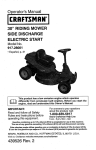
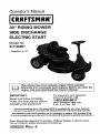
30" RIDING MOWER
SIDE DISCHARGE
ELECTRIC START
Model No.
917.28001
• Espafiol, p. 31
!
This product has a low emission engine which operates
differently
from previously
engine, read and understand
IMPORTANT:
Read and follow all Safety
Rules and Instructions before
operating this equipment.
built engines.
this Owner's
Before
you
Manual.
start
t
the
For answers to your questions
about this product, Call:
1-800-659.5917
Sears Craftsman Help Line
5 am - 5 pro, Mon- Sat
Gasoline containing up to 10% ethanol (El0) is acceptable for use in this machine.
The use of any gasoline exceeding 10% ethanol (El0) will void the product warranty.
Esta mdquina puede uU|izar gasoiina con un contenido de hasta el 10% de etanol (EIO).
El uso de una gasolina que supere el 10% de etanol (EIO) anulard la garantla del producto.
Sears Brands Management Corporation, Hoffman Estates, IL 60179 U.S,A.
Visit our Craftsmanwebsite:v,.ww.sears,com/craftsman
439526 Rev. 4
1
Warranty .................................................
2
Safety Ru_es ...........................................
3
Product Specifications
............................
6
Assembly!Pre-Operation
........................
7
Operation ..............................................
11
Maintenance Schedule .........................
18
Maintenance. ........................................ 18
Service and Adjustments ...................... 23
Storage ................................................. 27
Troubleshooting .................................... 28
Sears Service ........................ Back Cover
Craftsman Riding Equipment Warranty
CRAFTSMAN FULL WARRANTY
FOR TWO YEARS from the date of purchase, all non-expendable parts of this riding equipment are
warranted against any defects in material or workmanship. A defective non-expendable part will
receive free in-home repair or replacement if repair is impossible.
FOR FIVE YEARS from the date of purchase, the frame and front axle of this riding equipment are
warranted against any defects in material or workmanship. A defective frame or front axle will receive
free in-home repair or replacement if repair is impossible.
FOR 90 DAYS from the date of purchase, the battery (an expendable part) of this riding equipment
is warranted against any defects in material or workmanship (our testing proves that it will not hold a
charge). A defective battery will receive free in-home replacement.
ADDITIONAL LIFETIME LIMITED WARRANTY on CAST IRON FRONT AXLE (if equipped)
FOR AS LONG AS tT IS USED by the original owner after the fifth year from the date of purchase, the
cast iron front axle (if equipped) of this riding equipment is warranted against any defects in matedal or
workmanship. With proof of purchase, a defective cast front axle will receive free in-home replacement.
WARRANTY SERVICE
For warranty coverage detaiJs to obtain free repair or replacement, call 1-800-659_5917 or visit the
web site: www.craftsman.com
in all cases above, if part repair or replacement is impossible,the riding equipment will be replaced
free of charge with the same or an equivalent model.
All of the above warranty coverage is void if this riding equipment is ever used while providing
commercial services or if rented to another person.
This warranty covers ON['( defects in material and workmanship. Warranty coverage does NOT
include:
• Expendable parts (except battery) that can wear out from normal use within the warranty period,
includingbut not limited to bIades, spark plugs, air cleaners, belts, and oil filters.
• Standard maintenance servicing, oil changes, or tune-ups.
• Tire replacement or repair caused by punctures from outside objects, such as nails, thorns,
stumps, or glass.
• Tire or wheel replacement or repair resulting from normal wear, accident, or improper operation or
maintenance,
• Repairs necessary because of operator abuse, including but not limited to damage caused by
towing objects beyond the capability of the riding equipment, impacting objects that bend the
frame, axle assembly or crankshaft, or over-speeding the engine,
• Repairs necessary because of operator negligence, including but not limited to, electrical and
mechanical damage caused by improper storage, failure to use the proper grade and amount
of engine oil, failure to keep the deck clear of flammable debris, or failure to maintain the riding
equipment according to the instructions contained in the operator's manual.
• Engine (fuel system) cleaning or repairs caused byfuel determined to be contaminated or oxidized
(stale). In general, fuel should be used within 30 days of its purchase date.
- Normal deterioration and wear of the exterior finishes, or product label replacement.
This warranty gives you specific legal rights, and you may also have other rights which vary from
state to state.
Sears
Brands Management
Corporation,
Hoffman
Estates,
IL 60179
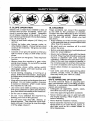
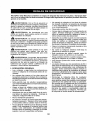
DANGER: This cutting machine is capable of amputating hands and feet and throwing
objects. Failure to observe the following safety instructions could result in serious injury
or death.
• Never direct discharged material toward
anyone. Avoid discharging
material
against awall or obstruction. Material may
ricochet back toward the operator. Stop
the blade when crossing gravel surfaces.
° Do not operate machinewithoutthe entire
grass catcher, discharge chute, or other
safety devices in place and working.
• Slow down before turning.
• Never leave a running machine unattended. Always turn off blade, set parking brake, stop engine, and remove keys
before dismounting.
• Disengage blade when not mowing. Shut
off engine and wait for all parts to come
to a complete stop before cleaning the
machine, removing the grass catcher, or
unclogging the discharge chute.
• Operate machine only in daylight or good
artificial light.
• Do net operate the machine while under
the influence of alcohol or drugs.
• Watch for traffic when operating near or
crossing roadways.
• Use extra care when loading or unloading
the machine into a trailer or truck.
• Always wear eye protection when operating machine.
- Data indicates that operators, age 60
years and above, are involved in a large
percentage of riding mower-related injuries. These operators should evaluate
their ability to operate the riding mower
safely enough to protect themselves and
others from serious injury.
• Keep machine free of grass, leaves or
other debris build-up which can touch hot
exhaust / engine parts and burn. Do not
allow the mower deck to plow leaves or
other debris which can cause build-up to
occur. Clean any oil or fuel spillage before
operating or storing the machine. Allow
machine to cool before storage.
_WARNING:
In order to prevent accidental starting when setting up, transporting,
adjusting or making repairs, always disconnect spark plug wire and place wire where
it cannot contact spark plug.
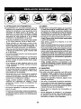
_WARNING:
Do not coast down a hill
in neutral, you may lose control of the riding mower.
_ WARNtNG" Engine exhaust, some of its
constituents, andcertain vehicle components
contain or emitchemicals known to the State
of Californiato causecancer and birth defects
or other reproductive harm.
_,WARNING:This
unit is not intended
for the use of wheel weights. Only use
attachments designed specifically for this
riding mower.
_WARNING:
Battery posts, terminals
and related accessories contain lead and
lead compounds, chemicals known to the
State of California to cause cancer and birth
defects or other reproductive harm. Wash
hands after handling.
!. GENERAL OPERATION
• Read, understand, and fotlow all instructions on the machine and in the manual
before starting.
• Donot put hands orfeet near rotating parts
or under the machine. Keep clear of the
discharge opening at all times.
• Only allow responsible adults, who are
famitiar with the instructions, to operate
the machine.
• Clear the area of objects such as rocks,
toys, wire, etc., which could be picked up
and thrown by the blade.
• Be sure the area is ctear of bystanders
before operating. Stop machine if anyone
enters the area.
Never carry passengers.
Do not mow in reverse unless absolutely
necessary. Always lookdown and behind
before and while backing.
3
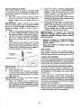
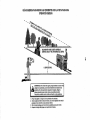
II. SLOPE OPERATION
Slopes are a major factor related to loss of
control and tip-over accidents, which can
result in severe injury or death. Operation
on all slopes requires extra caution, if you
can not back up the slope or ifyou feel uneasy
on it, do not mow it.
- Mow up and down slopes (15° Max), not
across.
• Watch for holes, ruts, bumps, rocks, or
other hidden objects. Uneven terrain could
overturn the machine. Tail grass can hide
obstacles.
• Choose a tow ground speed so that you
will not have to stop or shift while on the
slope.
• Do not mow on wet grass. Tires may lose
traction.
• Always keep the machine in gear when
going down slopes. Do not shift to neutral
and coast downhill.
• If machine stops while going uphill,
disengage blade, shift into reverse and
back down slowly.
• Avoid starting, stopping, or turning on a
siope. Ifthetires Iosetraction, disengage
the blade and proceed slowly straight down
•the slope.
• Keep all movement on the slopes slow and
gradual. Do not make sudden changes
in speed or direction, which could cause
the machine to roll over.
IlL CHILDREN
Tragic accidents can occur if the operator
is not alert to the presence of children.
Children are often attracted to the machine
and the mowing activity. Never assume
that children will remain where you last
saw them,
° Keep children out of the mowing area and
in the watchful care of a responsible adult
other than the operator.
, Be alert and turn machine off ff a child
enters the area.
- Before andwhile backing, look behind and
down for small children.
• Never carry children, even with the blade
shutoff, They mayfalloffand beseriously
injured or interfere with safe machine
operation, Children who have been given
rides in the past may suddenly appear in
the mowing area for another ride and be
run over or backed over by the machine.
• Never a[Iow children to operate the machine,
• Use extra care when approaching blind
corners, shrubs, trees, or other objects
that may block your view of a child.
IV, SERVICE
SAFE HANDLING OF GASOLINE
To avoid personal injury or property damage, use extreme care in handling gasoline.
Gasoline is extremely flammable and the
vapors are explosive.
• Extinguish all cigarettes, cigars, pipes,
and other sources of ignition.
° Use only approved gasoline container.
° Never remove gas cap or add fuel with
the engine running, Allow engine to cool
before refueling,
• Never fuel the machine indoors.
• Never store the machine or fueI container
where there is an open flame, spark, or
pilot light such as on a water heater or
other appliances.
- Use extra care while operating machine
with grass catchers or other attachments;
they can affectthe stability of the machine,
• Do no use on steep slopes.
, Do not try to stabilize the machine by
putting your foot on the ground.
• Do not mow near drop-offs, ditches, or
embankments, The machine could suddenly roll over if a wheel is over the edge
or if the edge caves in.
4
• Never
fillcontainers
insidea vehicle
.
•
•
•
or
on a truck or trailer bed with plastic liner.
Always place containers on the ground
away from your vehicle when filling.
Remove gas-powered equipmentfrom the
truck or trailer and refuel it on the ground.
]f this is not possible, then refuel such
equipment with a portable container, rather
than from a gasoline dispenser nozzle.
Keep the nozzle in contact with the rim
of the fuel tank or container opening at
all times until fueling is complete. Do not
use a nozzle lock-open device.
Iffuel is spilled on clothing, change clothing
immediately,
Never overfill fuel tank. Replace gas cap
and tighten securely.
GENERAL SERVICE
• Never operate machine in a closed area,
• Keep all nuts and bolts tightto be sure the
equipment is in safe working condition.
o Never tamper with safety devices. Check
their proper operation regularly.
• Keep machine free of grass, leaves, or
other debris build-up. Clean oil orfiJel spillage and remove any fuel-soaked debris.
Allow machine to cool before storing.
• If you strike a foreign object, stop and
inspectthe machine. Repair, if necessary,
before restarting.
• Never make any adjustments or repairs
with the engine running.
• Checkgrass catchercomponentsandthe
discharge chute frequently and replace
with manufacturer's recommended parts,
when necessary.
. Mower blade is sharp. Wrap the blade or
wear gloves, and use extra caution when
servicing them.
• Check brake operation frequently. Adjust
and service as required.
• Maintain or replace safety and instruction
labels, as necessary.
. Be sure the area is clear of bystanders
before operating. Stop machine if anyone
enters the area.
. Never carry passengers.
• Do not mow in reverse unless absolutely
necessary. Always look down and behind
before and while backing.
5
PRODUCT
SPECIFICATIONS
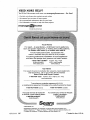
REPAIR PROTECTIONAGREEMENTS
Congratulations on making a smart purchase. Your new Craftsman® product is
designed and manufactured for years of
dependable operation. But like all products,
it may require repair from timeto time. That's
when having a Repair Protection Agreement
can save you money and aggravation.
Purchase a Repair Protection Agreement
now and protect yourseff from unexpected
hassle and expense.
Gasoline Capacity
and Type:
1.5 Gallons
Unleaded Regular
Oil Type
(API SG-SL):
SAE 30 (Above 32°F)
SAE 5W30 (Below 32°F
Oil Capacity:
48 Oz.
Spark Plug:
Champion RC12YC
(Gap: .030")
Ground Speed
(Mph):
Forward:
Reverse:
Charging System:
3 Amps @ Battery
Here's what's
Blade Bolt Torque:
45-55 Ft. Lbs.
•
0-4
0-2
CONGRATULATIONS
on your purchase of
a new riding mower. It has been designed,
engineered
and manufactured
to give you
the best possible dependability
and performance.
U nlimited service and no charge for parts
and labor on all covered repairs,
Should you experience
any problem you
can not easily remedy, please contact a Sears
or other qualified service center. We have
competent,
well-trained
representatives
and the proper tools to service or repair this
riding mower.
Please read and retain this manual.
The
instructions will enable you to assemble and
maintain your riding mower properly. Always
observe the "SAFETY RULES".
CUSTOMER
included in the Agreement:
Expert service by our 12,000 professional
repair specialists.
•
Product replacement
product can't be fixed.
if your
covered
•
Discount of 10% from regular price of
service and service-related
parts not
covered bythe agreement; also, 10% off
regular price of preventive maintenance
check.
Fast help by phone - phone support
from a Sears representative
on products
requiring in-home repair, plus convenient
repair scheduling.
Once you purchasethe Agreement, a simple
phone call is all that it takes for you to schedule service, You can call anytime dayor night,
or schedule a service appointment online.
Sears has over 12,000 professional repair
specialists,
who have access to over 4.5
million quality parts and accessories. That's
the kind of professionalism you can count on
to help prolong the life of your new purchase
for years to come. Purchase your Repair
Protection Agreement today!
RESPONSIBILITIES
• Read and observe the safety rules.
• Follow a regular schedule in maintaining,
caring for and using your riding mower.
o Follow the instructions under Maintenance
and Storage sections of this manual.
_WARNING:
This riding mower is
equipped with an internal combustion engine and should not be used on or near any
unimproved forest-covered, brush-covered
or grass-covered land unless the engine's
exhaust system is equipped with a spark
arrestor meeting applicable local or state
laws (ff any). tf a spark arrestor is used, it
should be maintained in effective working
order by the operator.
Inthe state of California the above is re quired
by law (Section 4442 of the California Public
Resources Code). Other states may have
similar laws. Federal laws apply on federal
lands. A spark arrestor for the muffler is
available through your nearest Sears service
center (See REPAIR PARTS manual).
Some limitations and exclusions apply.
For prices and additional information call
1-800-827-6655.
SEARS INSTALLATION
SERVICE
For Sears professional installation of home
appliances, garage door openers, water
heaters, and other major home items, in the
U.S.A. call 1-800-4-MY-HOME®
6
steering
Wheel_
_
Insert
Steering
(t) 5/16-18
Hex Bolt
'
Steering
Extension
(1) Rear Bumper
Wheel
(1) Front Bumper
x 4
(1) Lookwasher
_
Shaft
=
Steering
Boot
Steering
Adapter
Steering
_
Wheel
ShaftCover
(1) Large
Washer
(4)Screw
#10 x 0.200
Flat
(1) Shroud
(1) Cup Washer
#
Seat
(2) Key
Slope Sheet
(1)Knob
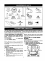
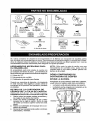
Your new riding mower has been assembled at the factory with the exception of those parts
left unassembled for shipping purposes, To ensure safe and proper operation of your riding
mower all parts and hardware you assemble must be tightened securely. Use the correct
tools as necessary to ensure proper tightness.
TOOLS REQUIRED FOR ASSEMBLY
NOTE: Only cut carton with a short blade
A socket wrench set will make assembly
utility knife, alongb[adeorsawcanpuncture
easier, Standard wrench sizes you need
tires on unit.
are listed below,
HOW TO SET UP YOUR RIDING
(1) 1/2" wrench
(1) Tire pressure gauge
(1) Utility knife
MOWER
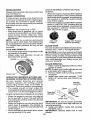
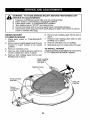
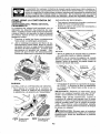
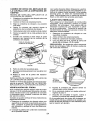
CHECK BATTERY
When right or teft hand is mentioned in
this manual, it means when you are in the
operating position (seated behindthe steering wheel),
TO REMOVE
Ensurebatteryissecurelyfastened, andthat
all wires are securely connected.
° Battery is located underthe seat,
• Battery has been fully charged from the
factory, before installation.
RIDING MOWER FROM
UNPACK CARTON
1, Remove all accessible loose parts and
CARTON
parts boxes from carton,
artery
of carton. Remove end panels and lay
side panels flat.
3. Remove packing materials from riding
mower.
2. Check
Cut along
dotted
lines on loose
all fourparts
panels
4,
for any
additiona]
or
cartons and remove,
Seat
7
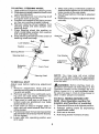
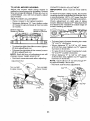
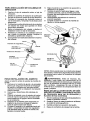
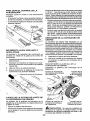
TO INSTALL STEERING WHEEL
1. Slide extension shaft onto steering shaft.
2, Slide steering shaft protective foam cover
over steering shaft.
3. Place steering boot over steering shaft
and push down to secure.
4. Position front wheels ofthe riding mower
so they are pointing straight forward.
5. Remove steering wheel adapter from
steering wheel and slide adapter onto
steering shaft.
7, Press steering wheel into position on
shaft, install large washer, lock washer,
bolt and tighten securely,
8. Snap steering wheel insert intocenter of
steering wheel securely.
7. Slide seat until a comfortable positionis
reached whichallows you to press clutch/
brake pedal all the way down.
8. Get offseat without moving its adjusted
position,
9. Raise seat and tighten adjustment knob
securely,
Seat Pan
Loc_
Washer
Insert
Steering
Steerir
TO INSTALL SEAT
Adjust seat before tightening adjustment
knob.
1, Remove adjustment knob and cup
washersecuring seat to cardboard packing and set aside,
2, Remove seatfrom the cardboard packing and set seat aside, Remove the
cardboard packing and discard.
3. Place seat on seat pan so all three (3)
bottom pads are positioned over large
slotted holes in pan.
4. Push down on seat to engage pads in
slots and pull seat towards rear of the
riding mower,
5. Pivot seat and pan forward and assemble
adjustment knob and cupwasher loosely,
Do nottighten,
6. Lower seat into operating position and
sit in seat,
NOTE: You may now roll your riding
mower off the skid. Follow the appropriate
instructionbelow to remove the riding mower
from the skid.
_JLWARNING: Before starting, read, understand and follow all instructions in the
Operation section of this manual. Be sure
riding mower is in a well-ventilated area.
Be sure the area in front of riding mower is
clear of other people and objects.
TO ROLL RIDING MOWER OFF
SKID (See Operation section for
location and function of controls)
1. Raise deck liftleverto its highest position.
2. Release parking brake by depressing
clutch/brake pedal.
3. Shift unit to neutral.
4. Roll riding mower forward off skid.
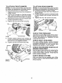
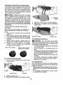
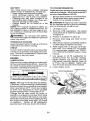
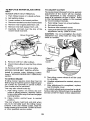
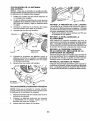
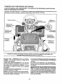
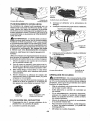
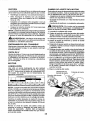
TO ATTACH FRONT BUMPER
NOTE: For ease of assembly, you maywish
to obtain the assistance of another person
for mounting bumper to riding mower.
1. Remove (2) screws from front chassis of
riding mower.
2. Tilt the front bumper so that the bumper
tabs catch the slots on the front of the
chassis and Iowerthe bumper in to place.
3. Attach the bumper to front of chassis with
screws removed in step 1.
4. Tighten the two (2)screws securely.
TO ATTACH REAR BUMPER
NOTE: For ease of assembly, you maywish
to obtain the assistance of another person
for mounting bumper to riding mower,
1, Remove (4) screws from rear chassis of
riding mower.
2, Position bumper as shown and assemble
to rear chassis with screws removed in
step 1,
3. Tighten the four (4) screws securely.
Buml
_"
Screw
Slot
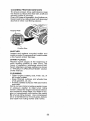
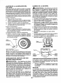
CHECK TIRE PRESSURE
Thetires on your riding mower were overinflated at the factory for shipping purposes.
Correct tire pressure is important for best
cutting performance.
FrontBumper
5. Position plastic shroud over bumper as
shown and loosely assemble to bumper
with the four (4) supplied screws.
6. Tighten all four (4) screws securely.
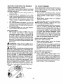
CHECK DECK LEVELNESS
For best cutting results, mower housing
should be properlyieveIed. See"TO LEVEL
MOWER HOUSING" in the Service and
Adjustments section of this manual.
Screws
CHECK FOR PROPER POSITON OF
MOWER DRIVE BELT
See thefigurethat is shown for replacing the
mower drive bett in the service and adjustmentsection ofthis manual, Veriiythat the
belt is routed correctly.
CHECK BRAKE SYSTEM
After you learn how to operate your riding
mower, check to see that the brake is operating properly,
Plasti(
Shroud
9
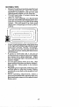
_CHECKLIST
Before you operate your new riding mower,
we wish to assure that you receive the best
performance and satisfaction from this
Quality Product.
Please review the following checklist:
,z All assembly instructions have been
completed.
v" No remaining loose parts in carton.
,/ Battery is properly connected.
J Seat is adjusted comfortably and tightened securely.
,/ All tires are properly inflated. (For shipping purposes, thetires wereoverinflated
at the factory,)
•/ Be sure mower deck is properly leveled
side.to.sideifront-to-rear for best cutting
results. (Tires must be properly inflated
for leveling.)
,/ Check mower belt. Be sure it is routed
properly around pulleys and inside all belt
keepers.
v" Check wiring. See that all connections
are still secure and wires are properly
clamped.
While learning howto useyour riding mower,
pay extra attention to the following Important
items:
v" Engine oil is at proper level.
v" Fueltank is filled with fresh, clean, regular
unleaded gasoline.
,/ Become familiar with all controls, their
location and function. Operate them
before you start the engine.
J Be sure brake system is in safe operating
condition.
V" Be sure Operator
Presence System and
Reverse Operation System (ROS) are
working properly (Seethe Operation and
Maintenance
sections in this manual.)
10
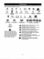
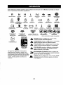
These symbols may appear on your riding mower or in literature supplied with the product.
Learn and understand their meaning.
R
N
REVERSE
NEUTRAL
H
Ikl
HIGH
LOW
CHOKE
FAST
SLOW
IGNITION
ENG|NE
OFP
REVERSE
OPERATION
ENGINE
ON
ENGINE
START
PARKING
BRAKE
PARKING
BRAKE
LOCKED
SWITCH
PARKING
BRAKE
UNLOCKED
SVSTEM(P_S)
FUEL
OIL PRESSURE
BATTERY
REVERSE
FORWARD
MOWER
HEIGHT
MOWER
LIFT
®@@@@
ATTACHMENT
CLUTCH
ENGAGED
ATTACHMENT
CLUTCH
DISENGAGED
DANGER,
KEEP HANDS
AND FEET AWAY
KEEP
AREA
CLEAR
(SEE
SAFETY
SLOPE
RULES
HAZARDS
SECTION)
DANGER
if not avoided,
will
result indicates
in death aorhazard
seriouswhich,
injury.
BRAKE/CLUTCH
PEDAL
WARNING
hazard
which,
if not avoided,
could
resultindicates
in deatha or
serious
injury.
CAUTION
indicates
a hazard
which, injury.
if not avoided,
might result
in minor
or moderate
Failure to follow instructions
could resuit in serious injury or
death. The safety alert symbol
is used to identify safety information about hazards which can
result in death, serious injury
and/or property damage,
CAUTION a when
used
without
alertinsymbol,
indicates
situation
that
could lhe
result
damage
to the tractor and/or engine.
HOT SURFACES indicates a hazard which,
if not avoided, could result In death, serious injury
and/or property damage.
FIRE indicates a hazard which, it not avoided,
could result in death, serious injury and/or
property damage=
11
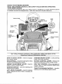
KNOW YOUR RIDING MOWER
READ THIS OWNER'S MANUAL AND SAFETY RULES BEFORE OPERATING
YOUR RIDING MOWER
Compare the illustrationswith your riding mower to familiarize yourself with the locations
of various controls and adjustments. Save this manual for future reference.
- Brake
Pedal
Deck Clutch
Lever
Ignition
Switch
Lift Lever
ThrofdeiChoke
Plunger
Height
Adju
Lever
/
Our riding mowers conform to the applicable safety standards
American National Standards Institute.
DECK CLUTCH LEVER - Used to engage
the mower blade.
BRAKE PEDAL- Used for braking the riding
mower and starting the engine.
HEIGHT ADJUSTMENT LEVER - Used to
adjust mower cutting height.
IGNITION SWITCH - Used for starting and
stopping the engine.
LIFT LEVER PLUNGER - Used to release
height adjustment lever when changing its
position.
12
Motion Control
Lever
of the
PARKING BRAKE LEVER - Locks parking
brake into brake position,
MOTION CONTROL LEVER - Selects the
speed and direction of the riding mower.
ROS "ON" POSITION-Allows operation of
mower deck or other powered attachment
while in reverse.
THROTTLE/CHOKE CONTROL- Usedfor
starting and controlling engine speed.
Theoperation
of any riding mower
can result in foreign objects thrown
into the eyes, which can result in severe eye damage. Always wear
safety glasses or eye shields while operating your riding mower or
performing any adjustments or repairs. We recommend a wide vision
safety mask over spectacles or standard safety glasses.
GROUND DRIVE • Tostop ground drive, depress brake pedal
all the way down.
• Move motion control leverto neutral position.
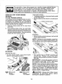
HOW TO USE YOUR RIDING
MOWER
TO SET PARKING BRAKE
Your riding mower is equipped with an operator presence sensing switch. When engine
is running, any attempt by the operator to
leavethe seatwithout first settingthe parking
brake will shutoff the engine.
1. Depress brake pedal all the way down
and hold.
2. Pull parking brake lever up and hold,
release pressure from brake pedal, then
release parking brake lever. Pedal should
remain inbrake position. Ensure parking
brake will hold mower secure.
ENGINE • Move throttle control between halfandfull
speed (fast) position.
NOTE: Failure to move throtUe control between half and full speed (fast) position, beforestopping, may cause engineto"backfire".
Throttle
STOPPING
MOWER BLADE , To stop mower blade, move deck clutch
lever to disengaged position.
, Turn ignition key to "STOP" position and
remove key. Always remove key when
leaving riding mower to prevent unauthorized use.
IMPORTANT: Leaving the ignitionswitch in
any position other than "STOP" will cause
the battery to discharge and go dead.
NOTE: Undercertain conditions when riding
mower is standing idle with the engine running, hot engine exhaust gases may cause
"browning" of grass. To eliminate this possibility, always stop engine when stopping
riding mower on grass areas.
(t'_1)
Deck Clutch
Control
"Engaged"
(t'_)
Deck Clutch
Control
"Disengaged"
_CAUTION:
Always stop riding mower
completely, as described above, before
leaving the operator's position.
13
TO USE THROTTLE CONTROL
Always operate engine at full speed (fast),
• Operating engine at less than full speed
(fast)reduces engine's operating efficiency.
• Full speed (fast) offers the best mower
performance.
Throttle
TO MOVE
FORWARD
AND BACkqNARD
The direction and speed of movement
controlled by the motion control lever.
is
Ensure the parking brake is applied.
2. Start riding mower with motion control
lever in neutral (N) position,
3,
Release parking brake.
4. Slowly move motion control lever to
desired position.
1.
Control
- The average lawn should be cut to approximately 2-1/2" during the cool season
and to over 3" during hot months, For
healthier and better looking lawns, mow
often and after moderate growth.
, For best cutting performance, grass over
6" in heightshould be mowed twice. Make
the first cut relatively high; the second to
desired height.
TO OPERATE MOWER
Your riding mower is equipped with an
operator presence sensing switch. Any
attempt by the operator to leave the seat
with the engine running and the deck Clutch
engaged will shut off the engine. You must
remain fully and centrally positioned in the
seat to prevent the engine from hesitating or
cutting off when operating your equipment
on rough, rolling terrain or hills.
1. Select desired height of cut.
2. Start mower blade by engaging deck
clutch lever.
TO STOP MOWER BLADE Disengage deck clutch lever,
DeckClutch Lever
MowerHeight
"Disengaged"Position
AdjustmentHigh
Level:
\
\
\
\
Deck Clutch Lever
"Engaged" Position
TO ADJUST MOWER CUTTING HEIGHT
The position of the mower height deck lift
lever determines the cutting height.
° Grasp lift lever.
• Press lift lever plunger with thumb and
move lever to desired position,
The cutting height range is approximately
1-1/2 to 4'L The heights are measured from
the ground to the blade tip with the engine
notrunning. These heights are approximate
and may vary depending upon soil conditions, height of grass and types of grass
being mowed.
Mower
Height Adjustment
Low Position
_IkCAUTION:
Do not operate the mower
without either the entire grass catcher, on
mowers so equipped, mulch cover, or the
deflector shield in place.
Deflector
14
Shield
MUlch Cover
REVERSE OPERATION SYSTEM (ROS)
Your riding mower isequipped witha Reverse
Operation System (ROS). Any attempt by
the operator to travel in the reverse direction with the deck clutch engaged will shut
offthe engine unless ignition key is placed
in the ROS "ON" position.
_kWARNING: Backing up with the deck
clutch engaged while mowing is strongly
discouraged. Turning the ROS "ON", to allow reverse operation with the deck clutch
engaged, should only be done when the
operator decides it isnecessaryto reposition
the machine with the attachment engaged,
Do not mow in reverse unless absolutely
necessary.
USING THE REVERSE OPERATION
SYSTEM Only use if you are certain no children or
other bystanders will enter the mowing
area,
1. Move motion control loverto neutral (N)
position.
2. With engine running, turn ignition key
counterclockwise to ROS "ON" position.
3, Look down and behind before and while
backing.
4. Slowly move motion control lever to
reverse (R) position to start movement.
5. When use of the ROS is no longer
needed, turn the ignition key clockwise
to engine "ON" position.
ROS "ON" Position
Engine "ON" Position
(Normal Operating)
TO ATTACH DEFLECTOR
1. Unhookthe 2 bungees from deck to the
mulch cover.
Shield
4. Rest the mulch cover on the deflector.
5. Attach the 1 bungee from the deflector
to the deck.
Deflector Shield
_Cover
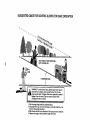
TO OPERATE ON HILLS
_bWARNING:
Do not drive up or down
hills with slopes greater than 15° and do not
drive across any slope, Use the slope guide
at the back of this manual.
o Choosetheslowestspeed before starting
up or down hills.
• Avoid stopping or changing speed on
hills.
• Ifstopping is absolutely necessary, push
clutch!brake pedal quickly to brake position and engage parking brake.
• Move motion control lever to neutral (N)
position.
• To restart movement, slowly release
parking brake and clutch/brake pedal.
• Make all turns slowly.
TO TRANSPORT
When pushing or towing your riding mower,
be sure to disengage trans mission by placing
shifter in neutral.
• Raise mower height adjustmenttoits high.
est position with mower height adjustment
lever,
• To reengage transmission, press brake
and shift out of neutral.
Bungee
Mulch Cover
Hinge Bracket
Bungee
2. Liftthe mulch cover.
3. Attach the deflector tothe hinge bracket.
15
BEFORE STARTING THE ENGINE
CHECK ENGINE OIL LEVEL
The engine in your riding mower has been
shipped, from the factory, already filled with
summer weight oil.
1. Check engine oil with riding mower on
level ground.
2. Remove oil fill cap/dipstick and wipe
clean, reinsertthe dipstick and screwcap
tight, wait for a few seconds, remove and
read oil level, If necessary, add oil until
"FULI_' mark on dipstick is reached. Do
not overfill.
° For cold weather operation you should
change oil for easier starting (See the oil
viscosity chart inthe Maintenance section
of this manual).
• To change engine oil, see the Maintenance section in this manual.
ADD GASOLINE
• Fill fuel tank to bottom of filler neck. Do
not overfill. Use fresh, clean, regular
unleaded gasoline with a minimum of
87 octane. (Use of leaded gasoline will
increase carbon and lead oxide deposits
and reduce valve life). Do not mix oiJwith
gasoline. Purchase fuel in quantities that
can be used within30 days to assure fuel
freshness.
_lb CAUTION: Wipe off any spilled oit or
fuel. Do not store, spill or use gasoline near
an open flame.
CAUTION: Alcohol btendedfuels (called
gasohol or using ethanol or methanol) can
attract moisture which leads to separation
and formation of acids during storage. Acidic
gas can damage thefuel system of an engine
while in storage, Toavoid engine problems,
the fuel system should be emptied before
storage of 30 days or longer. Drain the gas
tank, start the engine and let it run until the
fuel lines and carburetor are empty, Use
fresh fuel nextseason. See Storage Instructions for additionaF information. Never use
engine or carburetor cleaner productsin the
fuel tank or permanent damage may occur,
.v
FuelCap
16
TO START ENGINE
When starting the engine for the first time or
if the engine has run out of fuel, it will take
extra cranking time to move fuel from the
tank to the engine.
• Sit on seat in operating position, depress
clutch/brake pedal andset parking brake.
Place motion control lever in neutral
position.
• Move deck clutch lever to "DISENGAGED" position.
• Move throttle control to choke position.
NOTE: Before starting, read the warm and
cold starting procedures below.
• Insert key into ignition and turn keyclockwise to "START" position and release
key as soon as engine starts. Do not run
starter continuously for more than fifteen
seconds per minute. If the engine does
not start after several attempts, move
throttle control to fast position, wait a
few minutes and try again. If engine still
does not start, move the throttle control
back to the choke position and retry.
WARM WEATHER STARTING
(50°F/10°C AND ABOVE)
• When engine starts, move the throttle
control to the fast position.
• The ground drive can now be used. If the
engine does not accept the load, restart
the engine and allow it to warm up for
one minute using the choke as described
above,
COLD WEATHER STARTING
(50°F/10°C AND BELOW)
• When engine starts, allow engine to run
with the throttle control inthe choke position until the engine runs roughly, then
move throtfie controlto fast position. This
may require an engine warm-up period
from several seconds to several minutes,
depending on the temperature.
MOWING TIPS
• Mowershould be properly leveled for best
mowing performance, See "TO LEVEL
MOWER HOUSING" in the Service and
Adjustments section of this manual,
• The left hand side of mower should be
used for trimming.
• Drive so that clippings are discharged
onto the area that has already been cut.
Have the cut area to the right ofthe riding
mower. This will result in a more even
distribution of clippings and more uniform
cutting,
!i
°
•
°
•
•
When mowing lane areas, startbyturning
to the right sothatclippings willdischarge
away from shrubs, fences, driveways,
etc. After one ortwo rounds, mow in the
opposite direction making left hand turns
until finished.
If grass is extremely tall, it should be
mowedtwice to reduce toadand possible
fire hazard from dried clippings. Make
first cut relatively high; the second to the
desired height.
DO not mow grass when it is wet. Wet
grass will plug mower and leave undesirable clumps. Allow grass to dry before
mowing,
Regulate ground speed byselecting alow
enough gear to give the mower cutting
performance as well as the quality of cut
desired.
When operating attachments, select a
ground speed thatwill suit the terrain and
give best performance of the attachment
being used.
17
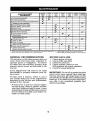
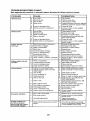
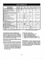
MAINTENANCE
SCHEDULE
SEFOEEEVEn
EACH
EVSR¥ EW_V EVERY svE_r_ SE_ORE
S
use
25;
.ouRs
.ouRs
.OURS
HH
Check
Brake
Operation
...... _,,
'R,. Check 33r. Pressure ....
V'
'--O
if
I
Check Operator
Presence & RO,S Systems
Check for Loose Fasteners
N
Check/Replace
G
c_ean Battery andTerm,inals
V
Mower
R i Chsck
I_=
V*
If
V' .................
SJ'
'V"'
'
if
.
..................
V'_
_,.i,_lii
Levelness
V-Belt
IHH.H I
Check Engine Oi_ Level
E
Change
N
clean Air Filler
G
Clean
|
STORAGE
.......
I1_
.........
LubI;icate
Axles and Sp;ndles
Check
SEASON
.................
V'
Mower Blade
W C_ea.R,iol_o.
SU_I_.......
E
100
.OURS
I
_#'
M Adjust Crutch
0
llll
Engin_
Oil
I
if
if
..................
V'r2
A_r Screen
Inspect
V¢_
Mu'hlertSpa_i'A'r;ester
ENI CIean En
ins Coolin
Replace
Spark
Plug
...... ,If,,
V'=
,
.........................................
If,
9 Fins
V _
V*
2
1-Cha_gr_mon_o_tenw_=_noperalir_gut)tJeraheawIoadotinhighambient_mpemtures.
3 - ,C!epl_c_bl_
2 _ _etv_ce m_
4 - C_S'B_ s_rfaces with isoptopyl _lr.choI ot _,1
o_en when oper_Ung
in dety o= dusly (;ondltlon_.
GENERAL RECOMMENDATIONS
The warranty on this riding mower does not
cover items that have been subjected to
operator abuse or negligence. To receive
full value from the warranty, operator must
maintain riding mower as instructed in this
manual.
BEFORE
EACH
mote ofl_n wtq_n mowing in sat_dy s_
fiImin_, r_an_r,
USE
1,
2.
3.
4.
Check engine oil level,
Check brake operation,
Check tire pressure.
Check operator presence and
ROS systems for proper operation.
5. Check for loose fasteners.
Some adjustments will need to be made
periodically to properly maintain your ridmg mower.
At least once a season, check to see if
you should make any of the adjustments
described in the Service and Adjustments
section of this manual.
IMPORTANT: Do not oil or grease the pivot
points which have special nylon bearings.
Viscous lubricants will attract dust and dirt
that will shorten the life of the self-lubricating
bearings. Ifyou feel they must belubricated,
use only a dry, powdered graphite type
lubricant sparingly.
. At least once a year you should replace
the spark plug, clean or replace air filter,
and check blade and belt for wear. A new
spark plug and clean airfilter assure proper
air-fuel mixture and help your engine run
better and last longer.
18
RIDING MOWER
Always observe safety rules when performing
any maintenance,
BRAKE OPERATION
If ridingmower requires more than four (4)
feet to stop at highest speed in highest gear
on a leve!, dry concrete or paved surface,
then brake must be serviced at your nearest
authorized service center.
TIRES
• Maintain tire pressure at t2 PSI.
• Keep tires free of gasoline, oil, or insect
control chemicals which can harm rubber.
• Avoid stumps, stones, deep ruts, sharp
objects and other hazards that may cause
tire damage,
NOTE: To seal tire punctures and prevent
flat tires due to slow leaks, tire sealant may
be purchased from your local parts dealer.
Tire sea!ant also prevents tire dry rot and
corrosion.
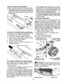
AXLE AND SPINDLES
• Frontwhee!axles and front spindles should
be properly lubricated.
• Wheel axles and spindles should be
lubricated with grease.
WheelSpindle
AyJe_
OPERATOR PRESENCE SYSTEM AND
REVERSE OPERATION SYSTEM (ROS)
Be sure operator presence and reverse
operation systems are working properly.
If your riding mower does not function as
described, repair the problem immediately,
• The engine should not start unless the
brake pedal isfullydepressed, andthe deck
clutch lever is in the disengaged position.
CHECK OPERATOR PRESENCE SYSTEM
• When the engine is running, any attempt
by the operator to leave the seat without
first setting the parking brake should shut
off the engine.
• When the engine is running and the deck
clutch lever is engaged, any attempt by
the operator to leave the seat should shut
off the engine,
• Neveroperatethe deck clutch lever unless
you are seated in the seat.
CHECK REVERSE OPERATION (ROS)
SYSTEM
• When the engine is running withthe ignition
switch inthe engine "ON" position and the
deck clutch lever engaged, any attempt by
the operator to shift into reverse should
shut off the engine.
• Whentheengineis running withthe ignition
switch in the ROS "ON" position and the
deck clutch lever engaged, any attempt by
the operator to shift into reverse should
NOT shut offthe engine.
ROS "ON"
Position
Engine "ON" Position
(Normal Operating)
BLADE CARE
For best results mower blades must be sharp.
Replace worn, bent or damaged blades,
&CAUTION: Use only a replacement blade
approved by the manufacturer of your riding
mower. Using a blade not approved by the
manufacturer of your riding mower is hazardous, could damage your riding mower and
void your warranty.
BLADE REMOVAL
1. Raise mower to highestposition to ailow
access to blade.
NOTE: Protectyour hands withgloves and/
or wrap blade with heavy cloth,
2. Remove blade bolt by turning counterclockwise,
3. Install new blade with stamped "THIS
SIDE UP" facing deck and mandrel assembly.
Mandrel
Assembly
Blade
Center Hole
IMPORTANT: To ensure proper assembly,
center hole in blade must align with star on
mandrel assembly.
4. Install and tighten blade bolt securely
(45-55 Ft. Lbs.).
IMPORTANT: Special blade bolt is heat
treated,
19
BATTERY
Your riding mower has a battery charging
system which is sufficient for normal use.
• Keep battery and connectors clean.
• Only recharge battery with charger
approved for a 12V 6 amp. hour battery.
• Charging with any other charger or an
automotive style charger can cause permanent damage to the battery.
• Charge battery for 24 hours for a full
charge,
NOTE: The original equipment battery on
your riding mower is maintenance free. Do
not attempt to open or remove caps or covers. Adding or checking level of electrolyte
is not necessary.
_WARNING:
Do not jump start battery.
Permanentdamage tothe battery or personal
injury may occur.
TRANSAXLE COOLING
Keep transaxle free from buUd-up of dirt and
chaff which can restrict cooling.
V-BELT
CheckV-belt for deterioration and wear after
100 hours of operation and replace if necessary. The belt is not adjustable. Replace belt
if it begins to slip from wear.
ENGINE
LUBRICATION
Only use high quality detergent oil rated with
API service classification SG-SL. Selectthe
oil's SAE viscosity grade according to your
expected operating temperature.
TO CHANGE ENGINE OIL
Determine temperature range expected
before oil change. All oil must meet AP(
service classification SG-SL.
•
•
Be sure riding mower ison levelsurface.
Oil will drain more freely when warm.
Catch oil in a suitable container.
CAUTION: If engine has been operated
for an extended period of time immediately
prior to draining oil, oil will be hot.
1. Lift engine cover.
2. Remove oil fill cap!dipstick. Be careful
not to allow dirt to enter the engine when
changing oil.
3. Position a container to catch oil.
4, Remove drain plug and drain oil into
container.
5. Afteroil has drained completely, replace
oil drain plug and tighten securely.
6. Refill engine with oil through oil fill dipstick tube. Pour slowly. Do not overfill.
For approximate capacity see "PRODUCT SPECIFtCATIONS"section ofthis
manual,
7. Use gauge on oil fill cap/dipstick for
checking revel, For accurate reading.
tighten dipstick cap securely onto the
tube before removing dipstick. Keep oil
at "FULL' line on dipstick, Tighten cap
onto the tube securely when finished.
8. Lower engine cover.
Engine
Oil Fill Cap/Dipstick
Drain Plug
NOTE: Although multi-viscosity oils (5W30,
10W30 etc,) improve starting incold weather,
the oils will result inincreasedoil consumption
when used above 32°F. Checkyour engine
oil Ievel more frequently to avoid possible
engine damage from running low on oil.
Change the oil after every 25 hours of
operation or at least once a year ifthe riding
mower is not used for 25 hours in one year,
Check the crankcase oil level before starting
the engine and after each eight (8) hours
of operation. Tighten oil fill cap/dipstick
securely each time you check the oil level.
20
Cover
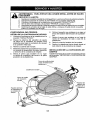
DECK WASHOUT PORT
Your riding mower's deck is equipped with
a washout port on its surface as part of its
deck wash system. It should be utilized after each use.
1. Drive the riding mower to a level, clear
spot on your lawn, near enough to a
water spigot for your garden hose to
reach.
IMPORTANT: Make certain the riding
mower's discharge chute is directed AWAY
from your house, garage, parked cars, etc.
Remove bagger chute or mulch cover if
attached.
2. Make sure the attachment clutch control
is in the "DISENGAGED" position, set
the parking brake, and stop the engine.
3. Thread the nozzle adapter (packaged
with your riding mower's Operator's
Manual) onto the end of your garden
hose.
4. Pull back the lock collar of the nozzle
adapter and push the adapter onto the
deck washout port at the left end of the
mower deck. Release the lock collar to
lock the adapter on the nozzle.
Nozzle
_
8.
Move the riding mower's attachment
clutch control to the "DISENGAGED"
position. Turn the ignition key to the
STOP position to turn the tractor's
engine off. Turn the water off.
9. Pull back the lock collar of the nozzle
adapter to disconnect the adapter from
the nozzle washout port.
10. Move the riding mower to a dry area,
preferably a concrete or paved area.
Place the attachment clutch control in
the "ENGAGED" position to remove
excess water and to help dry before
puttingthe riding mower away.
_ikWARNING: A broken or missing
washout fitting could expose you or
others to thrown objects from contact
with the blade.
* Replace broken or missing washout
fitting immediately, prior to using
mower again.
, Plug any holes in mower with bolts
and Iooknuts.
AIR FILTER
Your engine will not run properly using a
dirty air fifter. Service air cleaner more often
under dusty conditions. See engine manual.
Hose
Adapter_
Washout
CLEAN AIR SCREEN
Air screen must be kept free of dirt and chaff
to prevent engine damage from overheating.
Clean with a wire brush or compressed airto
remove dirt and stubborn dried gum fibers.
CLEAN AIR INTAKE/COOLING AREAS
To ensure proper cooling, make sure the
grass screen, cooling fins, and other external surfaces of the engine are kept clean
at all times.
Every t00 hours of operation (more often
under extremely dusty, dirty conditions),
removethe blower housing and other cooling
shrouds. Clean the cooling fins and external
surfaces as necessary. Ensure the cooling
shrouds are reinstalled.
NOTE: Operatingthe engine with a blocked
grass screen, dirty or plugged cooling fins,
and/or cooling shrouds removed will cause
engine damage due to overheating.
IMPORTANT: Tug hose ensuring connection is secure.
5. Turn the water on.
6. While sitting in the operator's position
on the riding mower, re-start the engine
and place the throttle lever in the Fast
",_" position.
IMPORTANT: Recheck the area making
certain the area is clear.
7. Move the riding mower's attachment
clutch control to the "ENGAGED" position. Remain in the operator's position withthe cuttingdeck engaged until
the deck is cleaned.
21
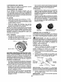
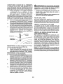
CLEANING FRICTION SURFACES
To ensure proper drive performance keep
the friction surfaces free from dirt, chaff and
excess rubber at all times,
Every 25 hours of operation, the friction surfaces need to be rubbed clean with isopropyl
alcohol or other non-filming cleaner.
\
Engine Plate
Friction Disc
MUFFLER
Inspect and replace corroded muffler and
spark arrester (if equipped) as it coutd create
a fire hazard and/or damage.
SPARK PLUG(S)
Replace spark plug(s) at the beginning of
each mowing season or after every I00
hours of operation, whichever occurs first.
Spark plug type and gap setting are shown
in "PRODUCT
SPECIFICATIONS"
section
of this manual.
CLEANING
• Clean engine, battery, seat, finish, etc. of
all foreign matter,
• Keep finished surfaces and wheels free
of all gasoline, oil, etc.
- Protect painted surfaces with automotive
type wax.
We do not recommend using a garden hose
or pressure washer to clean your riding
mower unless the engine and transmission
are covered to keep water out, Water in engine or transmission will shorten the useful
life of your riding mower. Use compressed
air or a leaf blower to remove grass, leaves
and trash from riding mower and mower.
22
_
SERVICE
ADJUSTMENTS:
ARNING:ORTO
AVOID SERIOUS INJURY, BEFORE PERFORMING ANY
1. Depress clutch/brake pedal fully and set parking brake.
2. Place motion control lever in neutral (N) position.
3. Place deck clutch in "DISENGAGED" position.
4. Turn ignition key to "STOP" and remove key.
5. Ensure the blade and all moving parts have completely stopped.
6. Disconnect spark plug wire from spark plug and place wire where it cannot
come in contact with plug.
RIDING MOWER
TO REMOVE MOWER
1, Place deck clutch in "DISENGAGED"
position.
2, Move mower height adjustment lift lever
forward to lower mower to its lowest
position.
3. Remove mandrel cover.
4, Remove pins holding left and right front
mower suspension arms in place.
5. Remove bolt holding deck front to rear
leveling rod in place.
6. Remove pin holding deck lift link arm in
place,
7. Remove bolt holding deck side to side
leveling rod in place.
8. Remove belt from around pulleys,
9. Slide deck out from under side of mower,
TO INSTALL MOWER
Install in reverse orderfollowing instructions
in "TO REMOVE MOWER" section,
Deck Leveling
Side to Side
Rod Bolt
MandrelCover
Front Leveling
Lift
Link Pin
Mower
Suspension
Arm Pin
23
TO LEVEL MOWER HOUSING
Adjust the mower while riding mower is
parked on level ground or driveway. Ensure
tires are properly inflated. If tires are over or
underinflated, you witl not properly adjust
your mower.
SIDE-TO-SIDE ADJUSTMENT
• Raise mower to its highest position.
• Measure distance "A" from bottom edge
of mower to ground level at front corners
of mower.
BottomEdge of
Mowerto Ground
.it
Toobtain the best cutting results, the mower
housing should be adjusted so that the front
is approximately 1/8" to 1/2" lower than the
rearwhen the mower is in its highest position.
Check adjustment on right side of riding
mower, Measure distance"F" directlyin front
and behind the mandrel at bottom edge of
mower housing as shown.
BottomEdgeof
Mowerto Ground
t .......... !,Ji
• To raisethe right side ofthe mower, tighten
lift link adjustment nut.
• Tolower the rightside ofthe mower, loosen
lift link adjustment nut,
NOTE: Each full turn of adjustment nutwill
change mower height about 3/16".
• Recheck measurements after adjusting.
Adjustment Nut
Turn nut left
to raise mower
FRONT-TO-BACK ADJUSTMENT
IMPORTANT: Deck must be level side-to
side.
Turn nut right
to lower mower
24
. To lower front of mower housing turn nuts
"G" and "H" clockwise.
. When distance "F" is 1/8" to 1/2" lower
at front than rear, tighten nut "H" against
trunnion on front link.
• To raise front of mower housing turn nuts
"G" and "H" counter clockwise.
• When distance "F" is 1/8" to 1/2" lower
at front than rear, tighten nut "H" against
trunnion on front link,
NOTE; Each full turn of "G" will change "F"
by approximately about 3/8".
• Recheck side-to-side adjustment,
TO REPLACE MOWER BLADE DRIVE
BELT
MOWER DRIVE BELT REMOVAL
1. Park riding mower on a level surface.
2. Set parking brake.
3, Lower mower to its lowest position.
4. Remove mandrei cover from mower deck.
5. Remove rear engine plate from unit.
6. Remove rear belt keeper from unit,
7, Carefully roll belt over the top of the
mower blade mandrel.
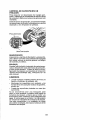
TO ADJUST CLUTCH
Toensure proper drive performance, periodic
adjustment of the clutch will be needed.
This adjustment is only necessary when
there is a reduction or loss of drive. Refer
to the maintenance section in this manual
for recommended intervals.
1. Park riding mower on a level surface.
2. Set parking brake.
3, Remove rear transax[e cover,
4, Using a 9/16th wrench, tighten the clutch
adjustment nut by 1/8th of a turn.
CAUTION: Do not over-tighten the clutch
adjustment nut. Only make as many 1/8th
turns as needed.
Mower Drive Belt
Belt
Idler Pulleys
Ma ldreI
8, Remove belt from idler pulleys.
9. Check idler pulleys to see that they rotate
freely.
10, Remove belt from rear drive pulley.
MOWER DRIVE BELT INSTALLATION
Install in reverse order following instructions in "MOWER DRIVE BELT REMOVAL"
section.
TO CHECK BRAKE
If riding mower requires more than four (4)
feet to stop at highest speed in highest gear
on a level, dry concrete or paved surface,
then brake must be serviced.
You may also check brake by:
1, Park riding mower on a level, dry concrete or paved surface, depress clutch/
brake pedal all the way down and engage
parking brake,
2. Place motion control lever in neutral
position.
The rear wheels must lock and skid when
you try to manually push the riding mower
forward. If the rear wheels rotate, then the
brake needs to be serviced. Contact a Sears
or other qualified service center,
25
Rear
Transaxle
Cover
Clutch
Adjustment
Nut
5, Test riding mower where it will be used
to cut grass.
6, If further adjustment is needed, return to
step 4.
7. After adjustment is completed, replace
rear transaxle cover.
If the clutch adjustment procedure is not effective, take your riding mower to a qualified
service center for repair and/or adjustment.
TO ADJUST STEERING WHEEL
ALIGNMENT
If steering wheel crossbars are not horizontal
(left to right) when wheels are positioned
straight forward, remove steering wheel
and reassemble per instructions in the
"INSTALL STEERING COLUMN" section
of this manual,
REPLACING BATTERY
n_asWARNING: Do not short battery termiby allowing awrench or any other object
to contact both terminals at the same time.
Before connecting battery, remove metal
bracelets, wristwatch bands; rings, etc,
Positive terminal must be connected first to
preventsparkingfrom accidental grounding.
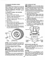
TO REMOVE WHEEL FOR REPAIRS
1. Lift seat pan to raised position.
2. Remove terminal cover.
3. Disconnect BLACK battery cable then
RED battery cable, battery strap and
carefully remove battery from riding
mower.
4. Installnew battery withterminals insame
position as old battery.
5. Reinstall terminal cover.
6. First connect RED battery cable to
positive (+) battery terminal with bolt and
nut as shown. Tighten securely.
7. Connect BLACK grounding cable
to negative (-) battery terminal with
remaining bolt and nut. Tighten securely
FRONT WHEEL
1. Block up front axle securely.
2. Remove dust cover, retaining ring, and
washer to allow wheel removal.
3, Repair tire and reassemble.
4. Replace washer and retaining ring
securely in axle groove.
REAR WHEEL
1, Block up Rear axle securely.
2. Remove dust cover, retaining ring, washer, and square key while pulling tire off.
3, Repair tire and reassemble.
4. Replace square keywhUeputting tire back
on, then replace washer and retaining
ring securely in axle groove.
8,
Lower seat pan.
Seat Pan
Washer
Retaining /
©
Dust
Cover
No,.b o jjNo,
Square Key
(rear wheel only)
NOTE: To seal tire punctures and prevent
flat tires due to slow leaks, purchase and
usetire seatantfrom Sears, Tire sealant also
prevents tire dry rot and corrosion,
TO START ENGINE WITH A WEAK
BATTERY
_ILCAUTION: Lead-acid batteries generate explosive gases. Keep sparks, flame
and smoking materials away from batteries,
Always wear eye protection when around
batteries.
Ifyour battery is too weak to startthe engine,
it should be recharged, (See "BATTERY" in
the Maintenance section of this manual).
INTERLOCKS AND RELAYS
Loose or damaged wiring may cause your
riding mower to run poorly, stop running, or
prevent it from starting.
• Check wiring. Ensure all wiring and connectors are secure.
ENGINE
Your carburetor is not adjustable. If your
engine does not operate properly due to
suspected carburetor problems, take your
riding mower to a qualified service center
for repair and/or adjustment.
26
Immediately prepare your riding mower for
storage at the end of the season or if the
riding mower will not be used for 30 days
or more,
_WARNING:
Neverstore the riding mower
with gasoline in the tank inside a building
where fumes may reach an open flame or
spark. Allow the engine to cool before storing in any enclosure.
MOWER
Remove deck from mower for winter storage.
When mower is to be stored for a period of
time, clean it thoroughly, remove all dirt,
grease, leaves, etc. Store ina clean, dry area.
1. Clean entire riding mower (Sea"CLEANING" in the Maintenance section of this
manual).
2. Inspect and replace belt, if necessary
(See belt replacement instructions in the
Service and Adjustments section of this
manual).
3. Lubricate as shown in the Maintenance
section of this manual.
4. Be sure that all nuts, bolts and screws
are securely fastened. Inspect moving
parts for damage, breakage and wear.
Replace if necessary.
5. Touch up all rusted or chipped paint
surfaces; sand lightly before painting.
BATTERY
• Fully charge the battery for storage.
• If battery is removed from riding mower
for storage, do not store battery directly
on concrete or damp surfaces.
ENGINE
FUEL SYSTEM
IMPORTANT: It is important to prevent
gum deposits from forming in essentialfuel
system parts such as carburetor,fuel hose,
or tank during storage. Also, alcohol blended
fuels (called gasohol or using ethanol or
methanol) can attract moisture which leads
to separation and formation of acids during
storage. Acidic gas can damage the fuel
system of an engine while in storage.
27
• Empty the fuel tank by starting the engine
and letting it run until the fuel lines and
carburetor are empty.
• Never use engine or carburetor cleaner
products in the fuel tank or permanent
damage may occur.
• Use fresh fuel next season.
NOTE: Fuel stabilizer is an acceptable alternative in minimizing the formation of fuel
gum deposits during storage, Add stabilizer
to gasoline in fuel tank or storage container.
Always followthe mix ratio found on stabilizer
container. Run engine at least 10 minutes
after adding stabilizer to allowthestabilizerto
reach the carburetor, Do not empty the gas
tank and carburetor if using fuel stabilizer.
ENGINE OIL
Drain oil (with engine warm) and replace
with clean engine oil. (See "ENGINE" in the
Maintenance section of this manual).
CYLINDER(S)
1. Remove spark plug(s),
2. Pouroneounce of oil through sparkplug
hole(s) into cylinder(s).
3. Turn ignitionkeyto "START" positionfor
a few seconds to distribute oil,
4. Replace with new spark plug(s).
OTHER
• Do not store gasoline from one season to
another.
• Replace your gasoline can ifyour can starts
to rust. Rust and/or dirt in your gasoline
will cause problems.
• Ifpossible, storeyour riding mower indoors
and cover it to give protection from dust
and dirt.
• Cover your riding mower with a suitable
protective cover that does not retain moisture. Do not use plastic. Plastic cannot
breathe which allows condensation to form
and will cause your riding mower to rust.
IMPORTANT: Never cover riding mower
while engine and exhaust areas are still
warm.
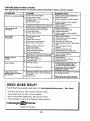
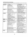
TROUBLESHOOTING CHART:
See appropriatesectionin manualunlessdirectedto Sears servicecenter.
PROBLEM
CAUSE
,,,,,,,,,,,,,,,
,,
Will
1
2
3
4
not start
CORRECTION
o_ effuel
1
.,,,,,,,,,,,.....
Fill fuel tank,
Bad spark plug,
2
RepIace
Dirty air filten
3
Clean/replace
Water in fuel.
4
Empty fuel tank & carburetor,
with fresh gasoline & replace
5
Check all wiring.
6
Contact a Sears or other qualified
service canter,
1
CIeanireptaee
5
Loose or damaged
6
End}no valves out of adjustment.
wiring.
Dirty air filter.
Hard to start
2
Bad spark plug.
!2
Loss
of power
vibration
Engine continues to
run when operator
leaves seat with attachment clutch engaged
refill tank
fuel fiIter,
air fiIter.
spark plug.
, Weak or dead battery,
3
Recharge
' Stale or dirty fuel.
4
Empty fueI tank and refill tank with
fresh, clean gasoline.
widng,
1
2
3
4
5
6
7
8
9
or replace battery.
5
Check all wiring.
6
Contact a Seers or other qualified
service center,
C,.tch/brake
pedai
.ot"_;p;&'sed. 1
Depress
Deck clutch is engaged.
2
Disengage
Weak or dead battery,
3
Recharge
Blown fuse,
4
Replace fuse,
5
Clean bakery term3nals.
B
Check all wiring,
Faulty ignEtion switch,
7
Check/replace
ignition
Faulty solenoid
8
Check/replace
solenoid
9
Corroded
battery term{na[s,
Loose or damaged
or starter.
presence
battery.
switch,
or starter.
battery.
1
Corroded
battery terminals,
2
Ctean battery terminals,
wiring.
3
Check all wiring,
Faulty solenoid or startar,
.................
,,,,,,,,,,, ,
Cutting too much grass/tee
4
Checklreplace
1
Raise cutting
Build-up of grass, leaves and trash
under mower,
2
Clean underside
3
D;rty air filter,
Low oil Ieve!/di_y- oil.
5
Faulty spark plug,
6
Stale or dirty fuel,
3
4
S
6
Cteanjreplace
4
Loose or damaged
switch(as),
deck cIutch,
or replace
Weak or
1
2
operator
clutch/brake pedal.
Contact a Sears or other qua[flied
service center,
,,,,,,,,,,,,,,,, ,,
Recharge or replace battery.
1
2
3
4
Fault,/
wiring,
fast,
Water in fuel.
Excessive
Replace
air filter.
3
Engine valves out of adiustmant.
Engine clicks but will
not start
spark plug,
4
Loose or damaged
Engine witl not
turn over
,,
solenoid
of mower
& regap
oil
or change
spark plug.
Empty fuel tank and refill tank with
fresh, eleaJ_ gasoline.
Empty fuel tank and carburetor,
tank with iresh gasoline.
8
Spark plug wire loose,
8
Connect
9
Dirty engine air screen/fins,
9
CIean engine air soree_fins,
10
Dirty/clogged
10
CleaWrepIace
11
Loose or damaged
12
Engine
I
speed.
housing,
air fiitar.
Check oil loyal/change
Clean
Or starter,
height/reduce
muffler,
wiring.
valves out of adjustment.
_,Worn, bent or toose blade.
2
Bent bfade mandrel
3
Leosetdamaged
& tighten spark plug wire.
muffler.
11
Cheek all wiring,
12
Contact a Sears or ether qualified
ServiCe cente£.
i_e'place
blade.Tighten blade bolt.
Contact a Sears or other qualified
service center.
part(s).
Faulty operator-safety
system,
refill
presence
28
T_ghten loose part(a),
_.Replace damaged pads.
ccntroI
Check wiring, switches and connections. If not sorres;_ed, contact a Sears
or ether qualified service center,
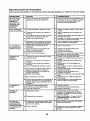
TROUBLESHOOTING
CHART:
See appropriate section in manual unless directed to Sears service center.
PROBLEM
Poor
CAUSE
cut - uneven
cuttin=
Worn, bent or loose brade.
4
5
,,,,,,,,
,,,,,,
Mower blade
not rotate
1
2
3
4
will
CORRECTION
1
2
3
1
2
3
Replace
Bent blade mandrel,
4
Cloggedmowardackventfrombu'JId-upol
grass, leaves, and trash around mandrel.
5
Contact a Seacs or other qualflied
service center,
Clean around mandrels to
open vent holes.
Mower deck not level,
BuiJdup of grass, leaves, and trash
u_der mowe_
Obstruction
in clutch mechanism.
Loss
of drive
""""i '
Engine dies when
riding mower is shifted
into reverse
,
housing,
Remove obstruction.
1
Travel speed too fast.
1
Shift to slower speed.
2
3
Wet grass,
Mower deck not _eveL
2
3
Allow grass to dry before mowing,
Level mower deck,
4
Check tires for proper PSI,
5
Replace/sharpen
bolt,
blade. Tighten
Clean underside
housing,
of mower
Repiase mower
ddve bell
mower
drive belt,
Frozen idler pulley.
4
5
! Low/uneven tire air pressure,
Worn, bent or loose blade,
6
Buildup of grass, leaves and
trash under mower.
7
Mower
8
Blade
9
,,,,
of mower
Frozen blade mandrel.
10
Battery will not
charge
deck,
Clean underside
2
3
4
Worn/damaged
,,,,,,,,,
Poor grass
discharge
blade, Tighten b_ade bolt.
Level mower
drive belt worn,
impropet/y
installed.
Improper blade used.
Clog gedmowerdackvent
from build, upo/
grass, leaves, and trash around mandrel,
7
8
9
10
Replace mower
drive belt.
Replace idler pulley,
Contact a Sears or other quaJified
service center.
blade
ReinstaIf blade sharp edge down,
Replacewithbladelistedinparts
manual,
Clean around mandrels to
open vent holes,
1
Bad battery cell(s).
2
Poor cable connections,
3
1
Faulty alternator,
.....
Axle key missing.
2
Clutch out of adjustment.
Adjust clutch, See "TO ADJUST
CLUTCH" in the Service and
Adjus_nents section.
1
Reverse operation
=ON" while mower
is engaged.
• Jm ignitionkey to ROS=ON
° position.
See Operation section,
2
Engine
1
2
3
Reptace
1
Install axle key at rear wheel', See
'TO REMOVE WHEEL' in the
Service and Adjustments
section,
,,,,
system (ROS} is not
or other attachment
is cold,
battery,
Chacktclean
allconnections.
Replace alternator.
AI[ow engine warm-up by running for
several seconds to sevsrBJ minutes.
r
I NEED MORE HELP?
¥ou_l find the answer and more on managemyhome.com
i • Find this and a[[ your other product rnanua[s online.
i " Get answers from our team of home exped:s.
i " Get a personalized maintenance plan for your home.
i • Find information and took to help with home projects.
manage
home
brought
to you by Sez_s
29
- for free'
SUGGESTED
o
GUIDE
FOR SIGHTING
SLOPES
ONLY RIDE UP AND
NOT ACROSS HILL
15 DEGREES
DOWN
FOR SAFE OPERATION
HILL,
MAX.
down the face of slopes, never across the face. Do not mow
WARNING: To avoid serious injury, operate your tractor up and
slopes greater than 15 degrees. Make turns gradually to prevent
tipping or loss of control. Exercise extreme caution when
changing direction on slopes.
1. Fold this page along dotted line _ndieated above.
2. Hold page before you so that its left edge is vertically paratlel to e tree
trunk or other upright structure.
3. Sight across the fold in the direction of hill slope you want to measure.
4. Compare the angle of the fold with the slope of the hill,
Garantfa ................................................
Regfas de seguridad .............................
Especificaciones
del producto ..............
Ensamblado/Preoperaci6n
...................
Operaci6n .............................................
31
32
35
36
40
Programa de rnantenimiento ................
Mantenimiento ......................................
Servicio y Ajustes .................................
AImacenamiento ...................................
Soiuci6n de problemas .........................
47
47
52
56
57
Garantia para equipos tractores Craftsman
GARANTiA COMPLETA DE CRAFTSMAN
PeR DOS AI_OS desde la fecha de compra, todas las partes no sustituibies de este equipo tractor estdn
garantizadas centre cualquier defecto de material o mane de obra. Una parte no sustituible defectuosa
recibir_ reparaci6n o reemplazo gratuito en case si la reparaciSn es imposible.
PeR CJNCO AI_.TOSdesde Ia fecha de compra, el bastidor y el eje delantero de este equipo tractor est_.n
garantizados centre cualquier defecto de material o mane de obra. Un bastidor o eje delantero defectuoso
recibir_ reparaei6n o reemplazo gratuito en case si la reparaci6n es imposJble.
DURANTE 90 D[AS desde Ia fecha de compra, la bateria (una parte sustituible) de este equipo tractor
est& garantizada contra cualquier defecto de matedal o mane de obra (nuestra prueba comprueba qua no
contendr_ carga). Una baterfa defectuosa recibir_ un reemplazo gratuito en casa.
GARANTiA LIMtTADA DE PeR V1DA ADICIONAL en el EJE DELANTERO
DE HIERRO COLADO (sl
est@ provisto)
DURANTE EL TtEMPO EN QUE SE USE per el propietario original despu@s del quinto aSo a partir de la
fecha de compra, et eje delantero de hierm co)ado (si est& provisto) de este equipo tractos estd garantizado
contra cualquier defecto de material o mane de ebra. Con el comprobante de comprs, un eje delantero de
hierra colado recibir,_ un reemplazo gratuito en cesa.
SERVICIO
DE GARANTIA
Para cenocer los detalles de la cobertura de garantia para obtener una reparaci6n o reemplazo
Ilame al 1-800-659-59t7
6 visite eI sJtio web: www. craftsman.corn
En redes los cases anteriores, si el reemplazo
el mismo modelo o uno equivalente,
es imposibfe,
el equipo tractor ser_, sustituido
gratuito,
sin cargo con
Toda Ia cobertura de garantia anterior ear& nu]a si este equipo tractor se utilize alguna vez pare brindar
servicios comerciales o si se alquila a otra persona.
Esta garantfa cubre 0 N ICAMENTE defectos de material y mane de obra. La cobertura de garantia NO inctuye:
• Partes sustituibles (excepto la baterfa) que se puedan desgastar pore! use normal dantro del per[ode de
garanfia incluso, pero sin [imitarse a, cuchillas, bujias, filtros de aire, coffees y filtros de aceite.
• Servicios de mantenimiento est_ndar' cambJos de aceite o afinaciones.
• Reemplazo o reparaci6n de neum#,ticos per pinshazos causados per objetos externos come clavos,
espinas, tocones o vidrios.
• Reemp]azo o reparaci6n de neum_ticos o ruedas per desgaste normal, accidentes o per operaci6n o
mantenimiento incorrectos.
•
Reparaciones necesarias per abuse del operador incluso, pare sin limitarse a, daf_os causados per
tame[car obietos que superen la capacidad deI equipo tractor, chocar centre objetos qua doblen el
bastidor, el ensemble deJ eje o el cig_JeSal o sobrepasar Javelocidad del motor,
, Reparaciones necesarias per negligencia del operador' incluso (pare sin limitarse a elI0) da_os et_ctricos
y mec&nicos causeries per el almacenamiento
incorrecto, per no user el grade y la cantidad correctos de
aceito de motor, per no mantener de! muelle libra de residues inflamables o per no mantener et equipo
tractor de acuerdo con Ias instrucciones qua contiene el manual del operador.
• Limpieza o reparaciones
del motor (sistema de combustible) cuando se determine
qua se us6
combustible contaminado y oxidado (sarro). En general, el combustible debe usarse dentro de los 30
dfas posteriores a su compra.
• Deterioro y desgaste normal de los acabados exteriores o sustituci6n de r6tuios de productos.
Esta garantia te otorga derechos regales especfficos, y usted tambi_n puede tarter otros derechos que
vat|an de un estado a otro.
Sears Brands Management Corporation, Hoffman Estates, IL 60179
31
PELIGRO: Esta Maquina cortadora es capaz de amputar las manosy los pies y de lanzar objetos. si no ee observan las instrucciones de seguridad siguientes se pueden producir lesiones
graves o la muerte.
£t
,@_ ADVERTENCIA: Con el fin de prevenir un
arranque accidental cuando configure, transporte,
ajuste o repare _am&quina, siempre desconecte
el cable de la bujia y coloque el cable donde no
pueda entrar en contacto con Ia bujla.
_IbADVERTENCIA:
No descienda per una
colina on neutral, pues puede perder el control
de la cortadora de c_sped.
_kADVERTENCIA:
Et escape del motor, algunas de sus partes y ciertos componentes deI
vehfculo contienen o emiten productos qufmicos
de los que se sabe en el Estado de California que
causan cancer y defoctos de nacimiento u otros
daSos reproductivos.
_ADVERTENCIA:
Esta unidad no es para
usarse con pesas para ruedas. Use s6Io ac*
cesorios diseriados especificamente para esta
cortadora de c6sped.
_
ADVERTENCIA: Los postes, tasterminales
y los accesorios relacionados de la bateria contienen plomo y compuestos de plomo, productos
quimicos de los que se sabe en el Estado de
California que causan cancer y defectos de nacimiento u otros daSos reproductivos.
I. OPERACION
GENERAL
° Lea, entienda y siga todas Ias instrucciones
sobre la mAquina en el manual antes de comenzar.
• No coloque las manes ni los pies cerca de
las partes giratorias ni debajo de la mAquina,
Mant@ngasealejadode Ia abertura de descarga
en todo memento.
• $5Io pormita que los adultos responsables,
que est_n familiarizados con Ias instrucciones,
operen la mAquina.
- Ubere el Area de objetos come piedras, juguetes, cables, etc., pues podrian atraparse y
Ianzarse con Ia cuchilla.
• Aseg0rese de que el Area est_ Iibre de curiosos antes de operar la mAquina, Detenga la
m&quina si alguien entra en el Area,
• Nunca transporte pasajeros.
• No corte en reversa, a menos que sea absolutamente necesario. Siempre mire hacia abajo
y hacia atr&s antes y cuando vaya on reversa.
• Nunca dirija el material que se descarga hacia
nadie. Evite descargar el material contra una
pared u otra obstrucci6n, El material puede
rebotar hacia el operador, Detenga la cuchilla
cuando cruce per superficies con grava.
32
• No maneje la mAquina si no tiene el colector
de c@spedcomplete, fa canaleta de descarga
u otros dispositivos de seguridad en su lugar
y en funcionamiento.
• Desacelere antes de dar la vuelta.
• Nunca deje Ia mAquina on funcionamiento sin
vigilar, Siempre detenga la cuchilla, active el
freno de estacionamiento, detenga el motor y
retire la Jlaveantes de descender.
• Desactive la cuchilla cuando no est_ cortando
c_sped. Apague el motor y espere hasta que
todas Ias partes se detengan per complete
antes de Iimpiar la maquina, retirar el colector
de c_sped o destapar la canaleta de descarga,
• Opere Ia mAquina 5nicamente durante el dia
o con buena luz artificial,
• No opere Ia maquina mientras est@bajo la
influencia de alcohol o drogas,
• Est@ pendiente deI trAfice cuando opera [a
mAquina cerca de caminos o at cruzados.
• Tonga cuidado extreme cuando cargue o descargue Ia mAquina de un trailer o cami6n,
• Use siempre protecci6n ocular cuando opera
la m&quina.
• Los dates indican que los operadores de 60 5
m&s aSos de edad entran en un alto porcentaje
de lesiones relacionadas con cortadoras de
cL=sped. Estos operadoros deben evaluar su
habilidad para operar la cortadora de c_sped
en forma su_cientemente segura come para
pretegerse a si mismos y a los demAs de una
Iesi6n grave.
• Mantenga la mAquina Iibre de cualquier
acumulaci6n de c@sped,hojas u otra basura,
puespodrlan entrar en contacto con el escape
caliente y!o las partes del motor y quemarse,
No permita que la plataforma de la cortadora
de c@sped levante hojas u otra basura que
puedacausar acumulaciones. Limpie cualquier
derrame de aceite o combustible antes de
operaro almacenar la mAquina. Permita que
la mAquina se enfr_e antes de almacenada.
!i. OPERACION
EN PENDIENTES
III. NIl,lOS
Las pendientes son un factor principal que se
relaciona con la p_rdida de control y los accidentes de votcaduras, [oque puede dar come
resultado una lesi6n grave o la muerte. La
operaci6n en todas las pendientes requiere
tenet precauciones extras. Si usted no puede
retroeeder de una pendiente o si se siente
inc6modo en ta pendiente, no la pode.
• Pode las pendientes hacia arriba y hacia abajo
(a 15 ° come mAximo), no de un lade a otro.
• Tenga cuidado con los hoyos, surcos, protuberancias, piedras y otros objetos ocultos. El
terreno disparejo podrfa volcar la m_quina. El
c_sped alto puede esconder los obst&culos.
• Elija una vefocidad terrestre baja de mode que
no tenga que detenerse o girar mientras est_
en la pendiente.
• No corteelc_sped h_medo. Lasllantas pueden
perder su tracci6n.
• Mantenga siempre la m&quinaen una velocidad
cuando baje per las pendientes. No cambie a
neutral ni vaya en punto muerto hacia abajo
en una colina.
• Si la mEquina se para rnientras sube per una
colina, desactive la cuchilla, cambie a reversa
y baje despacio.
• Evite arrancar, parar o girar en una pendiente.
Si las llantas pierden su tracci6n, desactive la
cuchilla y proceda con lentitud en linea recta
hacia aba|o per la pendiente.
Pueden ocurrir accidentes tr&gicos si el operador
no est& alerta ante la preseneiade nifios. Con
frecuencia los niSos se sienten atraidos per
Ia m&quina y la actividad de corte do c_sped.
Nunoa d_ per un hecho que los nifios permanecer&n donde usted los vie per _ttima vez.
° Mantengaalosnifiosalejadosdet&readecorte
y bajo la supervisi6n de un adulto responsable
a parte del operador.
° Est_ alerta y apague la m&quina si un nifio
entra en el &tea.
• Antes y mientms avance en reversa, mire hacia
arras y hacia abajo per si hay nifios presentes.
• Nunca tleve n[fios arriba de la m&quina, incluso
cuando la cuchilla est@desactivada. Pueden
caerse ytesionarse gravemente o interferircon
Ia operaci6n segura de Ia m_,quina, Los nifios
a quienes se les da una vuelta en la m&quina
pueden aparecer de repente en el_eade corte
para otra vuelta y ser atrope!lados o golpeados
con la m&quina.
• Nunca permita que los nP,osoperen la m&quina.
• Tenga cuidado extreme aI acercarse a las
curvas sin vieibilidad, arbustos, &rboles u otros
objetos que puedan bloquear su visi6n e impedir
observar a un nifio.
IV. SERVICIO
manejo seguro de la gasolina
Para evitar una Iesi6n personal o un daSo en ta
propiedad, tenga cuidado extreme al manejar
la gasolina. La gasolina es extremadamente
inflamable y los vapores son explosives.
• Apague toscigardllos, habanos, pipas y otras
fuentes de ignici6n,
- Use sSIo un recipiente de gasolina aprobado.
• Nunca retireel tap6n de la gasolina ni agregue
combustible con el motor en funcionamiento.
Permita que el motor se enfrie antes de volver
a tlenar el tanque de combustible,
- Nunca liene la m&quina de combustible en
interiores.
• Mantenga todo el movimiento lento y gradual
sobre Ias pendientes. No haga eatables repentinosde velocidad o direcci6n, pues podria
causar que Ia mEquina se vuelque.
• Tenga cuidaod extreme mientras opera la
maquJna con colectores de c6sped u otros
accesorios; pueden afectar la estabilidad de
la m&quina.
• No la use sobre pendientes pronunciadas.
• No intente estabilizar la m&quina poniendo el
pie en el suelo.
• Nocortecercadedeclives,zanjasoterraplenes.
La m&quina podria volcarse de repente si una
rueda pasa sobre la orilla o si la onlla termina
on un hoyo.
• Nunca almacene la mAquina o el recipiente
de combustible donde haya una flama abierta, chispa o una luz de piloto come Fade un
calentador de agua u otros aparatos.
33
• Nunca Ilene tos recip]entes adentro de un
vehfculo o en un cami6n o trailer con forro de
pI_stico+ Coloque siempre los recipientes en el
suelo y lejos de su veh{culo durante el Ilenado.
• Retire el equipo que funciona con gaso]ina del
cami6n o trailer y rell_nelo en el suelo, Si esto
no es posible, entonces rellene este equipo
con un recipiente port&til, en lugar de hacerlo
directamente con la boquilla del dispensador
de gasolina.
• Mantenga la boquilla en contacto con el borde
del tanque o recipiente de combustible abri_ndolo en todo momento hasta que el llenado
de combustible est_ completo. No use un
dispositivo que mantenga abierta Ia boquitla.
• Si el combustible se derrama sobre la ropa,
cAmbiesela de inmediato.
• Nunca Ilene de m&s el tanque de combustible.
Vuelva a coEocar el tap6n de Ia gasotina y
apri_telo bien.
S ERVICIO GENERAL
• Nunca opere la m,_quina en un &rea cerrada.
• Mantengatodaslastuercas y pernos apretados
paraasegurarse de queelequipo seencuentra
en condiciones de trabajo seguras.
• Nunca manipule los dispositives de seguridad.
Revise con regularidad que operen bien+
• Mantenga la m&quinalibre de cualquier acumulaci6n de c_sped, hojas u otra basura. Limpie
los derrames de aceite o combustible y retire
cualquier basura que contenga combustible+
Permita que la rn,4quina se enfrle antes de
almacenarta+
• Si usted golpea un objeto extrafio, det_ngase
e inspeccione la m_.quina. Rep&rela, de set
necesario, antes de volver a empezar.
• Nunca haga ajustes o reparaciones con el motor
en funcionamiento.
• Revise Ioscomponentes del colector de c_sped
y la canaleta de descarga con frecuencia y
sustituya con repuestos recomendados por el
fabricante cuando sea necesario.
° La cuchilla de la cortadora de c6sped tiene fire.
Envuelva la cuchilla o use guantes y tenga
precauci6n extrema cuando les de servicio.
• Revise la operaci6n deI freno con frecuencia+
Ajuste y d_ servicio segen sea necesado.
• Conserve o cambie las etiquetas de seguridad
e instrucciones seg_n sea necesario+
• AsegSrese de que el &rea est_a Iibre de curiosos antes de operar Ia m&quina+ Detenga la
m_.quina si alguien entra en el &rea.
• Nunca transporte pasajeros.
• No corte en reversa, a menos que sea absolutamente necesario. Siempre mire hacJa abajo
y hacia atr_,s antes y cuando vaya en reversa+
34
ESPECIFICACIONES
DEL PRODUCTO
iCapacidad de
gasolina y Tipo:
1.5 Galleries (5.6 L)
Regular sin plomo
Tipo de Aceite
(API-SG-SL):
SAE 30 (Sobre 32°F/0°C)
SAE 5W30 (Dsabaje32°F/0°C)
Capacidad
de aceite:
48 onzas
Bujfa:
Velocidad de
Recarrido:
MphiKph)
Champion RC_2YC
(Abertura: .030"/0,76 mm)
Marcha
Adelante:
0 - 4/6,4
Atr&s:
0- 2/3,2
Sistema de
Carga
:3 Amps Bateria
ACUERDOS
DE_PROTECCION
PARA
LA REPARACION
Congratulaciones porsu buena compra. Su nuevo
producto Craftsman_ est,. disefiado y fabdcado
para funcionar de mode liable per muchos aries.
Pete come todos los productos, puede necesitar
a[guna reparaci6n de tanto en tanto, En este case
tenet un Aeuerdo de Protecci6n para la ReparaciSn puede hacerles ahorrar dinero y fastidios,
Compre ahera un Acuerdo de Proteccibn para
la Reparaci6n y prot_gese de molestias y gastos
inesperados.
Un Acuerdo incluye los puntos siguientes:
• Servicio experto de nuestros t2.000 especiaIistas profesionales en la reparaci6n.
• Servicio ilimitado sin cargo alguno para
Ias partes y Ia mane de obra sobre todas ]as
reparaciones garantizadas.
Torque de} perno 45-55PiesAJbras(62-75Nm)
de la cuchilla:
FELICITACIONES per Ia compra de su cortadora
de c_sped. Ha side disefiado, ptanificadoy fabricado para dade la mejor confiabilidady el meier
rendimiento posible.
En el case de que se encuentre con cualquier
prob]ema que no pueda solucionar f_.cilmente,
haga el favor de ponerse en contacto con un
centre de servicio Sears o con un otro centre de
servicio cualificado. Cuenta con representantes
bien capacitados y competentes y con las herramientas adecuadas para darie servieio o para
reparar este cortadora de c6sped.
Haga ei favor de leer y de guardar este manual.
Estas instruc-ciones ]e permitir_n montar y mantener su unidad en forma adecuada, Siempre
observe las "REGLAS DE.SEGURIDAD/'
RESPONSABILIDADES
DEL CLIENTE
• Lea y observe las reglas de seguddad.
• S[ga un programaregular al darle mantenimiento, cuidados y use a su cortadora de c_sped.
° S[ga Ias instrucciones de las secciones de
"Mantenimiento" y '_lmac_enamiento" de este
manual deI propietario.
• Sustituci6n del producto si su producto
garantizado no puede set arreglado.
• Descuento de110% sobre el precio corriente
del servicio y de ]as partes relativasal servicio
no cubiertas per el acuerdo; tambi_n el 10%
menos sobre el precio corriente de un control
de mantenimiento preventive.
• Ayuda r_plda portet_,fono-soportetelefSnico per parte de un representante Sears sobre
productos que requieren un arroglo en casa, y
ademds una programaci6n sobre los arreglos
m,_s convenientes.
Cuando se ha comprado el Acuerdo, basta con
una Ilamadate]ef6nica para programarel se_cio.
Puede Ilamar cuando quiera, dia y noehe o fijar
en Iinea una oita para obtener el servicio. Sears
tiene m&s de 12.000 especialistas profesionaies
en la reparaci6n, que tienen acceso a m&s de
4.5 millones de partes y accesodos de calidad.
Este es el tipo de profesionalidad con que puede
eontar para ayudar a alargar la vida de{ producto que acaba de comprar, per touches aries.
iCompre hey su Acuerdo de Protecci6n para la
Reparaci6n!
Se aplican algunas limitaciones y exclusiones.
Para conocer los precios y tenet rods Informaci6n, Ilame a! 1-800-827-6655.
ADVERTENCIA:
Esta cortadora de c_sped est& equipada con un motor de combustiSn
interna y no se debe usar en o cerca de terrenos
cubiertos de bosques sin mejoras, cubiertos de
arbustos o cubiertos de pastes, a menos que
el sistema de escape dei motor est_ equipado
con un parachispas que eumpla con las leyes
locales o estatales aplicables (de haberlas). Si
se usa un parachispas, el operador deberd dade
mantenimiento en un orden de trabajo elective.
SERVICIO
DE INSTALACI6N
SEARS
Para ta instatacidn profesionat Sears de aparatos de casa, puertas de garaje, calentadores de
agua y otres importantes articulos para la casa,
en U.S.A Ilamar a
1-800-4-MY-HOME®
En el estado de California, las leyes exigen el use
de un parachispas (Sec_ci6n4442 det C6digo de
Recursos P0b]icos de California). Otros estados
puedentenerleyes similares. En Iosterrenos federales se aplican las leyes federales. Se puede
obtener un parachispas para elsilenciador atrav_s
del centre de servicio autorizado rods cercano.
35
%
Volante
(1) Parachoques
de la d#ecci6n
traseros
(1) Paracboques
de]anteroe
de dimcci6n
(1) 5116q8
x 4
Pemo de cabeza
(1) Arandela
de seguridad
Cobertura
hexagonal
(4) TomilIo
#10 x 0.200
Ejede
Extenoi6n
Adaptador
(t) Arandelas
Asiento
(1) Shroud
(1) Arandela
taza
#
(2) Llave
Hoja de
pendiente
(1) Manilla de ajuste
Su nueva cortadora de c6sped se ha ensamblado en la f,_brica con excepci6n de aquellas partes
que se dejan sin ensamblar para el envio. Para asegurar la operaci6n segura y correcta de la oortadora de c6sped, todas las partes y la ferreteria que usted ensamble se deben apretar bien. Use Ias
herramientas correctas necesarias para asegurar un ajuste apropiado.
HERRAMIENTAS
NECESARIAS
EL ENSAMBLADO
PARA
El ensamb[ado set& m_ts simple si cuenta con
un conjunto de ltaves de cubo. Lostamales de
itave estAndar que necesita se indican en seguida.
(t) Llave de 1/2"
(1) Herramienta de cuchilia
(1) Calibrador de presi6n para Ilantas
CESPED
DE LA CORTADORA
DE
DE LA CAJA DE CARTON
DESEMPACADO
1,
2.
3.
4.
COMO CONFIGURAR SU
CORTADORA
DE Ct_SPED
REVISE LA BATERJA
AsegSrese de que la bateda est_ bien sujetada.
y que todos los cables est6n bien conectados.
•
La baterfa est_ ubicada debajo del asiento.
•
La baterla se ha cargado per completo en ]a
f#.bfica antes de su instalaci6n.
Cuando se menciona la derecha o la izquierda
en este manual, esto significa cuando usted se
encuentra en la posici6n de operaci6n (sentado
al volante).
RETIRO
NOTA: $6Io corte la oaja de cart6n con una
herramienta de cuchilla corta, pues una de
cuchilla larga o una sierra pueden pinchar las
Ilantas de Ia unidad.
DE LACAJA DE CARTON
Retire todas las partes sueltas accesibles y
tas cajas de las partes del cart6n,
Corte Ias lineas punteadas de los cuatro
paneles de la caja de cart6n. Retire la caja
de cart6n y el marco superior como una sola
pieza.
Retire los materiales de empaque de la cortadora de c_sped,
Revise si hay cualquier parte sueltao cartones
adicionales y retirelos.
Aslento
36
r,a
PARA INSTALACION DE COLUMNA DE
DtRECCI6N
6.
I.
Deslice el eje de extensi6n sobre el eje de
direcci6n.
2.
Deslice la cubierta de espuma de protecci6n
(tel eje de direcci6n sobre el eje de direcci6n.
Coloque el manguito de direcci6n sobre el
eje de direcci6n y emp6]ejo hacia abajo para
asegurarlo.
Cofoque las ruedas de]anteras de lacorbadora
de c(_sped de modo que apunten en linea
recta hacia adelante.
Retire el adaptador del volante y deslice el
adaptador sobre e] eje de direcci6n.
Presione el volante en su posici6n sobre el
eje, instale la arandela grande, bloquee la
arandela y apriete bien el perno.
Co[oquebienel insertodelvolanteenelcentro
deI vo]ante.
3.
4.
5.
7.
8.
• Eje de
///_
extensi6n,,,_
_
"--,_
/_
Base del
As{ento
.
--_'--Cublerta de
espuma
Ele de
NOTA: Ahom puede sacar Jacortadora de c6sped
de latarima. Observe las siguientes inst_ucciones
apropiadas para retirar la cortadora de c_sped
de la tarima.
direcci6n
PARA INSTALACl6N
Baje el asiento a Ia posici6n de operaci6n y
si_ntese en el asiento,
7. Deslice el asiento basra que Ilegue a una
posici6n cbmoda, que le permita presionar
el pedal del embrague/freno compLetamente
hasta abajo.
8. Desm6ntese de[ asiento sin mover su
posici6n ajustada.
9. Levante el asiento y apriete la manilla de
ajuste en forma segura.
_),ADVERTENCIA:
Antes de empezar, tea,
entienda y siga todas las instrucciones de ]a
secci6n de Operaci6n de este manual. Aseg_rese
de que la cortadora de c6sped est_ en un _.rea
bien ventilada. Aseg_rese de que el &tea de
enfrente de la cortadora de c_sped est_ libre de
gente y objetos.
DEL ASIENTO
Ajuste el asiento antes de apretar la manitla de
ajuste.
1. Remueva la manilla de ajuste y la arandela
plana que aseguran el asiento al empaque
de cart6n y p6ngalos de Iado para poder
utilizarlos durante la instalaci6n del asiento
sobre e] tractor.
2. Remueva y desechese del embalaje de
cart6n.
3. Colocar el asiento yen e] asiento deI recipiente de manera que la tres (3) cojtns est_
posieionada en el agujero ancho ranurado
en e] recipiente.
4. Empujar en e] asiento para enganchar el
coitus en la ranura y empujar el asiento
hacia la parte trasera del tractor.
5. Pivotear el asiento y el recipiente hacia adelante y ensamblar el bot6n de regulaci6n
y la arandeJa taza de modo no fuerte. No
apretar enroscar fuerte.
PARA SACAR LA CORTADORA
DE CI£SPED DE LATARIMA
(Consulte ia secci6n
de Operaci6n
para ver la ubicaci6n
y
funci6n de los controles)
1. Eleve tapalanca deI elevador de la plataforma
hasta su posici6n m_c,Jma,
2. Suelte el freno de estacionamiento al Iiberar
el pedal deI embragueifreno.
3. Cambie unidad a Ia posici6n de neutro.
4.
37
Saque la cortadora de c6sped de la tarima.
COLOCACION
DELANTERA
DE LA DEFENSA
NOTA: Para que el armado Ie resulte senci]lo,
puede solicitar ayuda a otra personacuando monte
ta defensa en Ia cortadora de e@sped.
1.
Retire los tornillos (2) del chasis delantro de
Ia cortadora de c_sped,
Incline la defensa delantera de modo que las
pesta#,asde la defensa entren en las ranuras
del frente deI chasis y baje la defensa hacia
su lugar,
3. Coloque la defensa en el frente del chasJs
con los tornillos que retir6 en el paso 1.
4. Apriete bien los dos (2) tornilIos,
_'Parachoque8
2.
Eti_
t_'assros
REVISE
LA PRESION
DE LAS LLANTAS
Las llantas de la cortadora de c_sped se inflaron
de m&s en la f_.brica para su transporte. Corregir
lapresi6nde lasI;antases importante paraobtener
el mejor desempe5o del corte,
• Reduzca la presi6n de las Ilantas a [a PSi que
se muestra en las l[antas.
REVISE LA NIVELAGION
PLATAFORMA
DE LA
Para obtener los mejores resultados de corte, la
carcasade lacortadorade c_sped sedebe nivelar
bien, Consulte la parte de "NIVELACI,ON DE LA
CARCASA DE LA CORTADORA DE CESPED" en
fa secci6n de Servicio y Ajustes de este manual.
Pern!
5.
6.
Iues
delanteros
Coloque la envoltura de pI_stico sobre la
defensa conforme se muestra y ens&mblela
holgadamente en Ia defensa con los cuatro
(4) tomilIos provistos.
Apdete bien los cuatro (4) tomilIos.
.,Tornitlo
COLOCAClON
,
DE LADEFENSATRASERA
NOTA: Para que el armado le resulte sencillo,
puede solicitar ayudaaotra personacuando monte
la defensa en Ia cortadora de c@sped.
1,
Retire los tornillos (4) del chasis trasero de Ia
cortadora de c@sped.
2. Coloque la defensa conforme se muestra
y ens&mblela en el chasis trasero con los
tornillos que retir6 on el paso 1,
...... 3, Apriete bien los cuatro (4) tornillos.
38
REVISE LA POSICION CORRECTA
DE LA CINTA DEL IMPULSOR DE LA
CORTADORA
DE CESPED
Observe lafigura que se muestra para cambiar la
cinta del impulsor de la cortadora de c6sped en
la seccibn de servicio y ajuste de este manual,
Verifique que la cinta est6 en la ruta correct&
REVISE EL SISTEMA DE FRENO
Despu_s de quehaya aprendido c6mo operar su
cortadorade c_sped, revise que elfreno funcione
bien. Consulte la parte de "AJUSTE DE FRENO"
en lasecci6n de Se[vicio yAjustes de este manual.
LISTA DE REVISION
Antes de operar su nueva cortadora de c_sped,
deseamos asegurarnos de que ustedobtenga el
mejordesempeSo y satisfacci6ndeeste Producto
de Ca[idad.
Per favor revise ta siguiente lista de revisi6n:
,,/ Todas las instrucciones de ensamblaje se ban
comple_do.
,/ No queda ninguna parte suelta en la caja de
cart6n.
J' La bateria est& bien conectada.
J
El asiento est_ ajustado c6modamente y bien
apretado.
€" Todas las Ilantas est&n bien infladas. (Las
[lantas se inflan de m&s en la f_brica para su
transportaci6n.)
,," AsegQrese de que Ia plataforma de lacortadora
de c_sped est_ bien nivelada de lade a lade
y del frente a la parte posterior para obtener
los mejores resultados de corte. (Las Ilantas
deben estar bien infladas para la nivelaci6n.)
,/ Revise la cinta de la cortadora de c_sped.
Aseg_rese de que est_ en la ruta correcta
alrededor de las poleas y adentro de todas
las sujeciones de la cinta.
J Revise el cableado. Aseg_rese de que todas
Ias conexiones est_n bien colocadas y que los
cables est_n bien sujetos.
AI aprender c6mo usar su cortadora de c6sped,
preste atenci6n extra a los siguientes puntos
importantes:
v" El aceite del motor estd en un nivel adecuado.
#" El tanque de combustible estd Ileno con gasolina sin plomo regular nueva y limpia.
J Familiaricese con todos los contro[es, su ubicaci6n y funci6n. Op_relos antes de arrancar
el motor,
d" AsegQrese de que el sistema de freno est& en
condiciones de operaci6n seguras.
J Asegurarse de que el Sistema de Presencia
del Operadory el Sistema de Funcionamiento
Atr&s (ROS) _5ancionande mode adecuado
IVer las Secciones de Funcionamiento y
Mantenimiento en este manual.)
39
Estos simbolos pueden aparecer en ]a cortadora de cSsped o en la literature provista con el producto. Aprenda y entienda su significado.
R
MARGHA
N
AT P,_S
H
NEUTRO
ALTO
L
.I' ,1
BAJO
ESTRANGU-
R.APIDO
LENTO
INTERRUPTOR
LACISN
MOTOR
APAGADO
SISTEMA
MOTOR
FLINCtQNAMIENTO
ENCENDIDO
MOTOR
EN MAACHA
DE ISNICI(_N
PRESISN
eEL AC E{TE
FRENO
DE
MANO SE CERRC)
FRENO DE
MANO ABIERTO
ATR_.S(ROe)
SOBRE LUZ DE
TEMPERATURAS
ACCESOR|O
OIEL
EMBRAGUE
ENGANCHADO
COMBUSTtBLE
PRESI(_N
DEL ACEITE
ACCESOR[O
DEL
EMBRAGUE
BATERiA
MARCHA
ATR_S
PELIGRO,
GUARDE LAS
MANOSY
LOS PIES LEJOS
MARCHA
HACIA ADELANTE
ALTURA DE LA
SEGADORA
MANTENGA
EL
AREA DESPEJADA
DESENGANCHADO
LEVANTAMIENTO
DE LA SEGADORA
PEUGROS
DE
PENDIENTES
(VeaIa secciSnde las reglasde ssguridad)
CONTROL
DE
RUEDA LISRE
DESACTIVADO
PEL|GRO muerte
indiea o
unlesiones
peligro que,
si no se evita,
provoca
graves.
PEDAt- DE
FRENOiEMBRAGUE
ADVERTENCIA
que,graves.
si no se evita,
puede
provocar indica
muetteun opeligro
]esionee
PRECAUCION indica un peligro que, si no se evita,
puede provocar lesiones ligeras o moderadas.
CO N*TROL DE
PRECAUCION
ACTIVADO
RUEDA LleRE
aviso, indica una situaciSn que puede provocar
daSos al tractor y/o al motor.
cuando se utiliza sin el simbolo de
No segui_ las siguientes instrucciones
SUPERFICIES CALIENTES indiea un peligro que,
puede provocar heridas o muerte. Los
si no se evita, puede provocar la muerte, lesiones
simbo]os de aviso de seguridadse utilizan
,,_,_,,_.__=.
graves y!o danos ala mdquina.
pare identificar informaciones de seguridad
relativas a peligros que puedenprovocar Ia _a_,
FUEGO indica un peligro que, si no se evila, puede
muerte, heridas graves y!o dafios ala
provocar la muerte, lesiones graves y!o danes
m,_quina.
ala mdquina.
4O
CONOZCA SU CORTADORA DE CI=SPED
LEA ESTE MANUAL DEL PROPIETARIO Y LAS REGLAS DE SEGURIDAD ANTES DE OPEPAR SU CORTADORA DE ClaSPED
Compare [as ilustraciones con su cortadora, de c6sped para familiarizarse con las ublcaciones de los
diferentes controles y ajustes. Conserve este manual para futuras consu[tas,
Pedal del freno
Freno de
(ROS) en
posici6n"on"
Palanca del
embrague de ]a
f:mbolo de la
palanca del
de arranque
Aceleracibn!
Estrangulacibn
de ajuste
de altura
de
control de
movimiento
Nuestra cortadora de c_sped cump[econlas normas de seguridad aplicablesdel
InstituteNacionat Estadounidense de Normas,
PALACA DEL EMBRAGUE DE LA PLATAFORMA - Se usa para activar la cuch{lla de la
cortadora de c_spedo
FRENO DE ESTACIONAMIENTO - Se usa para
frenar la cortadera de c_sped y arrancar el motor.
PALANOA DE AJUSTE DE ALTURA - Se usa
para ajustar Ja a[tura de torte de la cortadora
de c_sped.
INTERRUPTOR DE ARRANQUE - Se usa para
arrancar y detener el motor,
EMBOLO DE LA PALANCA DEL ELEVADOR Se usa para soltar la palanea de ajuste de a[tura
cuando se cambia su posiciSn.
PALANCA DE FRENO DE ESTACIONAMIENTO
- Fija e_freno de estacionamiento en la posic'_6n
de freno,
PALANCA DE CONTROL DE MOVIMIENTO SeIeceionalave_ocidady direcci6n de Ia cortadera
de eesped,
INTERRUPTOR DEL SISTEMA DE FUNCIONAMIENTO HACIA ATRAS (ROS) EN POS|CI6N
"ON"- Permitela operaciSndel conjunto segador
o otro accesorioaccionadomientras queen revds.
CONTROL DE ACELERACI6NIESTRANGU LACION - Se usa para hacer arrancar y controlarla
veloeidad del motor.
41
La operaci6n de cualquier cortadora de c_sped puede caasar que entren objetos extraSos en los ojos, Io que puede provocar un daSo severo en los mismos, Use siempre
tentes de seguridad o protecciones oculares mientras est_ operando ]a cortadora de
c_sped o realizando cualquier ajuste o reparaci6n. Se recomienda usar una careta
de seguridad de visi6n amplia sobre los anteojos o lentes de seguridad est&ndar,
COMO USAR LA CORTADORA DE
CESPED
ACT|VACION
DEL FRENO
CIONAMIENTO
tMPULS[(§N DE RECORRIDO -
DE ESTA-
La cor_adora de c_sped est& equipada con un
interruptor de detecci6n de presencia del operador, Cuando el motor est_ en funcionamiento,
cualquier intento del operador de dejar el asiento
sin primero activar el freno de estacionamiento
apagar& el motor.
1, Presione et pedal det freno completamente
hasta abajo y mant_ngalo presionado.
2. Jale y sostenga la palanca del #eno de estacionamiento hacia arriba, Iibere [a presiSn
deI pedal de freno y luego suelte la patanca
deI freno de estacionamiento. Et pedal debe
perrnanecer en posiciSn de frenado. Aseg_rese de que el freno de estacionamiento
mantendr& detenida la cortadora de c_sped,
• Para parar el mecanismo impulsor, presione el
pedal del freno completamente,
• Mueva Ia palanca de contro{ de movimiento a
Ia posici6n de neutro.
Palancade controlde movimiento
I
MOTOR • Mover Ia palanca de mando entre Ia posici6n
de veJocidad media y m,_xima (r_.pida).
AVISO:Si no se mueve la palanca de mando
entre la posici6n de velocidad media y m_txima
(r_pida), antes de pararse, se puede causar un
"retornode llama" del motor.
Control De
Ace]eraci6n
PARADA
CUCHILLA DE LA CORTADORA DE ClaSPED • Para detener la cuchilla de la cortadora de
c_sped, mueva la palanca del embrague de
Ia plataforma a la posiciSn de "desactivada".
• Gire ]a Ilave de ignici6n a la posiciSn de apagado "STOP" y remueva Ia tlave al abandonar
el cortadora de c_sped para evitar el uso no
autorizado,
IMPORTANTE: Dejando el interruptor de la
ignici6n en cualquier posici6n otra que "STOP"
causar i que la bateria se descargue (muerta).
AVlSO: Bajo ciertas condiciones, cuando el
cortadora de c_sped est#, parado con el motor
andando en vacio, los gases de escape del motor
caliente pueden hacer que el c6sped se ponga
"care." Para e]iminar esta posibilidad, siempre
pare el motor cuando pare el cortadora de c_sped
en &teas con c_sped,
_1_ PREOAUOI6N: Siempre pare el cortadora
de c6sped completamente, seg_n se ha descrito
anteriormente, antes de abandonar la posici6n
de{ operador,
(1_)
"Enganchado"
(Engaged)
(l'_l)"Desenganchado"
(Disengage_
42
PARA USAR EL CONTROL
ACELERACION
DE LA
Elrango de altu ra de cortees de apmximadamente
1-1/2 a 4". I.as alturas se miden desde el suelo
hasta la punta de la cuchilla con el motor sin funcionar. Estas alturas son aproxJmadas y pueden
variarseg_n lascondiciones del suelo, laalturadel
c_sped y Iostiposde c_spedes que sevan acortar.
• El c6spedpromediose debe cortaraproximadarnente a 2 !/2" (6.35 cm) durante fa temporada
fria y a m&s de 3" (7 cm) durante los meses de
ca]or. Para que el e__spedcrezca m&s sano y
tenga mejor aspecto, cbrtelo con frecuencia y
despu_s de un crecimiento moderado,
• Para un mejor rendimiento del corte, el c_sped
de m_.sde 6" (15.20 cm) de altura debe cortar
dosveces. Hagae] primercorte relativamente
alto; el segundo deber& ser a la alture,deseada,
Siempre opere el motor a una aceleraci6n
completa.
• Si el motor funciona a una velocidad inferior a
la m_,xima (r&pida), su rendimiento disminuye.
• El rendimiento 6ptimo se obtiene a lavelocidad
m&xima (r,_pida).
Control De
Aceleraci6n
OPERACION
MOVIMIENTO
HACIA ADELANTE
HACIA ATR ._.S
DE
La cortadora de c_sped est& equipada con un
interruptor de detecci6n de presencia del operador.
Cualquier intento del operador de dejar el asiento
con el motor enfuncionamiento yel embrague de la
plataformaactivado apagar_.eI motor. Usted debe
perrnanecer colocado por completo en et centro
de]asiento para evitar que el motor se desoriente
o se apague cuando opere el equipo sobre un
terreno Ileno de baches u ondutante o en colinas.
1. Seleccione Ia altura de corte deseada.
Y
La direcci6n y la velocidad del movimiento se
controla pot medio de Ia palanca de control de
movimiento.
2. Active la cuchilla de la cortadora de c_sped
aI accionar la palanca del embrague de la
plataforma.
1, Asegerese de que el freno de estacionamiento
est_ activado.
2. Arranque Ia cor_adora de c_sped con la paIanca de control de movimiento en Ia posici6n
neutral (N).
3. Ubere el freno de estacionamiento.
4.
DE LA CORTADORA
PARA DETENER LA CUCHILLA DE LA
CORTADORA DE CESPEDDesactive Ia palanca
plataforma.
Mueva lentamente ]a palanca de control de
movimiento a la posici6n deseada.
del embrague
PosiciSn
de "desactivada"
de la palancadel embrague
de la plataforma_
de la
Posici6nalta de
ajustede altura
de la cortadorade
\
AJUSTE DE LA ALTURA DE CORTE
LA CORTADORA
DE CF-SPED
DE
La posici6n de la palanca del elevador de Ia
plataforma de la cortadora de c6sped determina
la altura de corte.
Posici6n de "activada" de
[a paianca del embrague
de Ia plataforma
• Agarre Ia pafanca del elevador.
• Presione el _rnbolo de la palanca del elevador
con el pulgary mueva la pa[anca a la posici6n
deseada.
baja de
ajuste de altura de la
cortadora de c_sped
& PRECAUCI6N: No opera la cortadora de
c_sped sin el colector de c_sped entero, en las
cortadoras de c_sped equipadas con dste, o sin
la coraza del deflector en su sitio.
43
et_stica
Gorazadel deflector
Cubierta de la alcochadora
Cubiertade
[a alcochadora
3.
FUNOIONAMIENTO
ATRAS (ROS)
Su cortadora de c_sped est& equipada con un
Slstema de Operaci6n en Reversa (SOR). Cualquier intento per parte del operador de avanzar
en reversa con el embrague de la plataforma activado apagar& el motor, a menos que la [lave de
encendido est_ en Ia posici6n de "ENCENDIDO"
(ON) del SOR
4.
Coloque el deflector en fa abrazadera de
bisagra.
Coloque lacubier_ade pajotesobre el deftector.
soporte de la bisagra
_
ADVERTENOIA: ]r marcha atr&scon el embrague puesto para cortar, no es recomendable.
Poniendo el ROSen posiciSn "ON", para permitir
el funcionarniento atr&s con et embrague puesto,
se tiene que hacer s6Io cuando el operador io considera necesado para reposicionar la m&quina con
el dispositivo embragado. No siegue en rev_s
a menos que sea absolutamente necesario,
USAF{ EL SISTEMA DE FUNCIONAMIENTO
ATRAS -
4.
5.
deflector
5.
Utilice el cortadora de c6sped sotamente si estAseguro de que noingresar_n nifios ni otras personas
o animales al &tea deride se va a cortar el c_sped.
1. Mover la palanca de rnando del movimiento
en la posici6n neutre (N).
2. Con el motor en marcha, girar la Havedel interrupter de la ignici6n en el sentido inverse al
de [as agujas deI reloj hasta la posici6n "ON".
3. Mire hacia abajo y hacia atr&s no s61o antes
de ir marcha atr&s, sine mientras est_ yendo
marcha atr&s.
Mover despacio la palanca de mando del
movimiento hacia la posici6n arras (R) para
empezar el movimiento.
Cuando el use del ROSes m&s necesado, d6
vuelta a la Ilave de ignici6n en el sentido de
las agujas del reloj hasta la posici6n "ON".
Oorrea
ei&stica
Coloque la correa et&stica1 desde el deflector
a la plataforma.
Coraza deldeflector
OPERAClON
_
Cubierta de la
a[cochadora
EN COLINAS
ADVERTENCIA:
No conduzca hacia arriba
o hacia abajo en colinas con pendientes mayores
de 15° y noconduzcade un [adoa otroen ninguna
pendiente. Use Ia gufa de pendientes de Ia parte
posteriorde este manual.
Elija la velocidad m&s lenta antes de comenzar a bajar o subir colinas.
Evite detenerse o cambiar de velocidad en
las colinas.
Posici6n
ROS "ON"
COLOCACION
Si es absolutamente neoesado detenerse,
empuje con rapJdez et pedal del embrague/
freno a [a posici6n de freno y active el freno
de estacionamiento.
Motor en posici6n "ON"
(Operaci6n Normal)
DEL DEFLECTOR
•
I.
Desenganche las 2 correas el_sticas de [a
plataforma a Ia cubierta de pajote.
2. Levante la cubierta de pajote.
44
•
Mueva la palanca de control de movimiento
a Ia posiciSn neutral (N).
Para reiniciar el movimiento, sue]to despacio
el freno de estacionamiento y e[ pedal del
embragueifreno.
D6 todas las vueltas despacio.
TRANSPORTE
A1 empujar o remo[car la cortadora de c_sped,
aseg_firesede dasactivar tatransrnisi6n al colocar
]a palanca de velocidades en neutral.
• Eleve el ajaste de altura de ta cortadora de
c_sped a su pos[ci6n m&s alta con la paianca
de ajuste de altura de la cortadora de c_sped.
• Para volver a activar Ia transmisi6n, presione
el freno y cambie la palanca de velocidades de
neutral a otra posici6n.
ANTES
DEL
ARRANQUE
DEL
MOTOR
REVISE EL NIVEL DE ACEITE DEL
MOTOR
El motor de la cortadora de c_sped se envia
desde la fabrica ya Ilena con aceite de peso
para el verano.
1. Revise el aceite del motor con ]a cortadora
de cesped sobre un sue{o nivelado.
2. Retire el tap6WIa varilla de Ilenado de aceite
y Iimpiela con un patio, reinserte Ia varilta y
atorni[Ie bien el tap6n, espere unos cuantos
segundos, retirelo y verifique el niveI del
aceite. Si es necesario, agregue aceite hasta
que Hegue a la marca que dice "LI _NO" en
la varilla. No Io }lene de rn_s.
•
•
•
PARA HACER
ARRANCAR
EL MOTOR
At hacer arrancar el motor per la primera vez o
si se ha acabado el combustible deI motor, se
necesitar& tiernpo para et arranque extra para
mover el combustib[e desde el estanque hasta
el motor.
• Si_ntase en el sill6n en la posici6n de operac[6n, suefte el pedal deI freno y ponga el
freno de estacionamiento,
°
Para operarla en clirnair{o, usted debe cambiar
el aceite para obtener un arranque m&s f_cil
(Consulte [a tabla de viscosidad de aceite de
lasecci6n de Mantenimiento de este manual).
Para cambiar el aceite de] motor, consulte la
secci6n de Mantenirniento en este manual.
COMO AGREGAR
_, PRECAUCI6N: Los combustibles mezclados con alcohol (Itamados gasohol o que usan
etanol o metanol) pueden atraer la humedad, Io
que provoca Ia separaci6n y formaoi6n de &cidos
durante el almacenamiento. El gas &cido puede
daSare] sistema de combustible de un motor mientrasse encuentraen almacenarniento. Para evitar
problemas con elmotor, elsistema de combustible
se debe vaciar antes del almacemaniento durante
30 d_as o m&s. Drene el tanque de gasolina,
arranque el motor y h__galofuncionar hasta que
Ias lineas de combustible y el carburador est_n
vacfos. Use combustible nuevo en la pr6xima
temporada. Consulte tas Instruccionas de Aimacenamiento para obtener informaci6n adicionaI.
Nunca use productos limpiadores para motor o
carburador en el tanque de combustible porque
puede ocurrir un dafio permanente.
GASOMNA
Llene eltanque de combustiblehasta la parte
inferior del cuello de relleno. No Io Ilene de
m_.s. Use gasolina sin plomo regular nueva
y limpia con un minimo de 87 octanos. (Usar
gasolina con plomo incrementar&los dep6eitos de carbono y 6xido de plomo y reducir_.
la vida de la valvula). No mezcle aceite con
gasolina. Compre combustibleen cantidades
que se puedan usar en 30 dlas para asegurar
Ia frescura del combustible.
,_PRECAUCI6N:
Umpie cualquier derrame
de aoeite o combustible. No almasene, derrame
ni use gasolina cerca de una flama abierta.
Ponga Ia palanca de control de movimiento
en Ia posic[6nde neutro.
•
Mueva el embrague del accesorio a la
posici6n "DESENGANCHADO".
•
Mueva la palanca de controlde la aceleraci6n
a la posici6nde estrangulaci6n.
AVISO: Antes de arrancar, lea tas instrucciones siguientes para el arranque en clima frfo y
templado.
•
Inserte la Ilave en la ignici6n y gire la Ilave
en el sentido que giran Ias manillas del reloj
a la posicibn de arranque start, y suelte la
ilave tan pronto como arranque el motor. No
haga funcionar et arrancador continuamente
por m,_s de quince segundos pot minuto. Si
el motor no arranca despu6s de varios intentarlos, rnueva el control de la aceleraci6n a
la posici6n de r,_pido,espere unos cuantos
minutos y trate de nuevo. Si el motor s[guesin
funcionar,rnueva el control de la aceleraci6n
a la posici6n de estrangulacibn y intente de
nuevo.
ARRANQUE CO_] TIEMPO TEMPLADO
(50° F/t0°C Y MAS)
• Cuando arranque el motor, mueva el control
de la aceleraci6n a la posici6n de r_,,pido.
• Ahora puede usar el mecanismo dedesplazamiento. Si el motor no acepta la carga, vuelva
a encender el motor y perm|tale que se caliente durante un minuto usando el ahogador
conforme se describe arriba.
j Combustible
de tapa
45
ARRANQUE CON TIEMPO FRiO
(50 ° F!10°C Y MENOS)
AI hacer arrancar el motor, mantenga el
control de Ia aceleraci6n a la posici6n de estrangulaci6n hasta que el motor se catiente y
empieze funcionar maI. Una vez que empieze
a funcionar mal, mueva inmediatamente el
control de Ia aceleraci6n a la posici6n r&pida.
El calentamiento del motor puede tomar a
partir de varios segundos a varios minutos
(cuanto m&s fria es la temperatura, m&s largo
es el calentamiento).
CONSEJOS
PARA CORTAR
EL ClaSPED
La cortadora de c@sped debe estar bien
nivelada para que su desempeSo seaei
mejor. Consulte la parte de "NIVELACION
DE LA CARCASA DE LA CORTADORA DE
CESPED" en la secci6n de Servicio y Ajustes
de este manual.
•
•
El lado izquierdo de la cortadora de c@sped
se debe usar para podar.
Conduzca de manera que los recortes de descarguen sobre el Area que ya se ha cortado.
El Area de corte debe estar del lado derecho
de Ia cortadora de c_sped. Esto crear& una
distribuci6n mAs uniforme de los recortes y
un corte mAs un{forme,
f
,
J
Cuando corte Areas grandes, comience
girando hacia Ia derecha, de modo que los
recortes se descarguen lejos de los arbustos,
bardas, caminos, etc. Despu6s de una o dos
vueltas, corte en la direcci6n opuesta, dando
vueltas hacia la izquierda basra que termine,
Si el c_sped estA demasiado alto, se deberA
cortar dos veces para reducir la carga y ]a
posibilidad de un peligro de incendio per los
recortes secos. Haga el primer corte relativamente alto; el segundo deberA ser a la altura
deseada.
No corte el c6sped cuando est@h_medo. El
c@sped hSmedo taponarA ta cortadora de
c_sped y dejarA rnatas indeseab[es. Permita
que el c_sped se seque antes de podarlo.
Regule la velocidad terrestre al seleccionar un
avance Io suficientemente lento para ajustar
el desempeSo de corte de {a cortadora de
c_sped a.sicomo ta calidad deI corte deseada.
Cuando utilice accesorios, seleccione una
velocidad terrestre que se adapte al terreno
y obtenga el mejor desempeSo de[ accesorio
que est6 usando.
46
,
PROGRAMA
, , ,,,,,,
DE
C
I,_ operaci,_n
CAOAUSOHO_
iii
deI {reno
Reviser 16pre_i&nde I_.s |Iant_.s
Revis= I= p......
sistema ROS
..........
CAnA
B
MANTENtMIENTO
Revisar
,,,,,,,,,,,,,
AUTESDE
! ,,
,,,, ,,,,,, i
V'
V F
If
V"
CADA
i
CA_
CA_
_
rI_PORADA
HORAS
A_C_I_a_IE_'O
i
..........
i_ del opemdo"r'yel
.......................
A
Reviser que los b_oches no est_n sueltos
D
Reviserlcambiarlacuchilladelaaortadora
R
de c_sped
A
Limp|at
y t_
Lubrio_rloeelesy
ReviSer
_
,,
I= bater_r_
Limpie l....
if
..................
term_n_es
V p
.......
v'
husos
V
perfioies de frio0,6n
I_ n_velaoi6n
p
de ]a oortador-a
I1_
I_ cint_ en V
I_
H IIIHI
m i, ,HH,IIH,Hll,
V',:_
........
......................
de enfria_'niet',to
V'
V*_,
' '{1_'"
del motor
V*
Cambiar le.buiia
e! cattucho
V'
de p_pel
RECOMENDACIONES
I I II
V'2
Umpiar la pantalla de .aJ[e.
Inspecclonar el sllenciadodparachispas
Cambiar
de _re
I
I_
Revi,=_
'l ,_oi=e
de,mo,o_
M Limping'i= filtm de aire
las aletaS
v"
V',
Revisar et ntvel deI aoeite deI motor
RO Limp|at
V*
v'
de o_.ped
Reviser
V'
€1_
D ._j_t°,_|e_b,._uo
0
T
50
HOP_S HO_S
T
(_
CA_A
25
deI flitm
_
...................
if
_
GENERALES
ANTES DE CADA USO
1. Revise el nivel del ace|re del motor,
2, Revise [a operaci6n del freno.
3, Revise la presi_n de las tlantas.
4. Revise que los sistemas de presencia del
operador y de ROS funcionen bien.
5, Revise que los broches no est_,n sueltos,
La garantia pars esta cortadora de c_sped no
ampara los articulos que se han sometido al
abuso o ta negligenciade[operador, Para recibir
el valor completode la garantfa, el operadordebe
darle mantenimiento a la cortadora de c_sped
conforme se indica en este manual.
Ser& necesario hacer algunos ajustes en forma
peri6dica para mantener de manera correcta la
cortadora de c_sped,
IMPORTANTE: No aceite ni engrase los puntos
de los pivotes que tienen cojinetes de naUon
especiales. Los lubricantes viscosos atraerdn
el polvo y la suciedad, Io que reducir& ta vida de
los cojinetes autolubric_ntes. Si siente que se
deben lubricar, use s6Io un lubricante tipo graflto
en polvo moderadamente.
A] menos una vez cadatemporada, revise si usted
debe hacer alg_n ajuste conforme se describe en
la secci6n de Servicio y Ajustes de este manual.
• Ai menos una vez al afiousted deber&cambiar la
bujla, limpiar o cambiar el fi]tro de aire y revisar
s] la cuchil]aylacintaest&n desgas_adas. Una
nueva buj{a y un nuevo filtro de aire aseguran
la mezcla adecuada de aire y combustible, Io
que ayuda a que el motor funcione mejor y
dure m&s tiempo.
47
CORTADORA
DE CI=SPED
Siga siempre las reglas de seguridad cuando
realice cualquier mantenimiento.
OPEFIAGION
DEL FRENO
Si Ja cortadora de c@sped requiere m&s de
cuatro (4) pies (t.219 metros) pare detenerse
ala velocidad m_Lximasobre una superficie de
concreto o pavimento seco nivelado, entonces se
debe dar servicio al freno en el centro de servicio
autorizado m&s cercano.
LLANTAS
• Mantenga la presi6n de las tlantas a 12 PSI.
, Mantenga las Ilantas libres de gasoline, aceite
o quimicos para el control de insectos, pues
pueden daSar el caucho.
• Evite los palos, Ias piedras, los surcos
profundos, objetos fitosos y otros peligros que
pueden causer da_o en las llantas.
NOTA: Pare sellar ]as pinchaduras de las Uantas
y prevenir las Ilantas desinfladas debido a fugas
Ientas, puede comprar selfador de flantas con el
distdbuidor de partes local. El seltador de ilantas
tambi6n previene Ia podredura en seco y la
eorrosiSn de las Uantas.
EJE Y HUSOS
• Los ejes de las ruedas frontales y los husos
frontales se deben fubricar bien.
• Los ejes de ]as ruedas se deben ]ubricar con
un lubricante tipo grafito en polvo seco.
• Nuncaoperelapalancadelembraguede]aplataforma a menos que est_ sentado en elasiento.
VI_RIFII_Z SISTEMA FUNCIONAMIENTO
ATRAS (ROS)
• Cuando el motor est_ en rnarcha con el interruptor de tfave en posici6nde motor "ON" y el
embrague dot accesorio conectado, cualquier
tentative dot operador de viajar marcha atr&s,
apagar& et motor.
• Cuando el motor est& en marcha con el interruptor de llave del sistema de funcionamiento
atr&s (ROS) en la posici6n "ON" y el embrague
det accesorio conectado, cualquier tentativa del operador de viajar marcha atr&s, NO
apagar& el motor.
Posici6n
ROS "ON"
Motor en posici6n "ON"
(Operaci6n Normal)
CUIDADO DE LA CUCHILLA
Paraobtener los mejores resuttados, lacuchiIlade
]acortadorade c_sped debe ester afilada. Cambie
Ia cuchilta si est& desgastada, dobtada o daSada.
,_ PRECAUCI6N: Use s81o una cuchilia de
reemplazo aprobada pot el fabricante de la cotfedora de c_sped. User una cuchilla no aprobada
por el fabricante de la cortadora de c6sped es
peligroso, pues podria dahar ta cortadora de
c_sped y anular la garantia,
RETIRO
DE LA CUCHILLA
1.
Eje de ruedaD
Eleve la cortadora de c_sped ala posici6n
m&s alta pare tener acceso ala cuchiila.
NOTA: Prot_jase tas manos con guantes y/o
envuelva la cuchiifacon un paso grueso.
2, Retire el perno de la cuehilla gir&ndolo haoia
la izquierda,
3. instale la nueva cuchilla con el diseSo que
dice "ESTE LADO HACIA ARRIBA" hacia Ia
plataforma y el ensamblaje det mandril.
_"__
SiSTEMA PRESENCIA OPERADOR YSISTEMA FUNCIONAMIENTO
ATRAS (ROS)
Asegurarse de que el sistema de presencia del
operador, el sistema de trabajo y el sistema funcionamiento atr&s funcionen bien. Si tu cortadora
de c_sped no funci6n corno descrito, reparar el
problema lnmediatamente.
o El motor no arrancar& si el pedal de embrague/
freno est& completamente presionadoyel mando
del embrague deI accesorio est&desconectado.
VI_RIFIE_ZSrSTEMA PRESENCIA OPERADOR
Pemo
de cuchilla
Armado
(especial}
Cuohilte
• Cuando el motor est& en marcha, cualquier
tentative del operador de abandoner el asiento
sin haber puesto el freno de estacionamiento
primero, apagara el motor.
• Cuando el motor est,_en marcha y el embrague
del accesorio est& conectado, cualquier tentativa del operador de abandoner el asiento,
apagar& el motor.
IMPORTANTE: Pare asegurar un ensamblaje
correcto, el orificio central de la cuchilla se debe
alinear con la estrella del ensamblaje deI mandril
4. lnstale y ajuste bien eI perno de ta cuchilla
(45 - 55 pies/Libras).
IMPORTANTE: El pemo de la cuchilla especial
est& tratado con calor.
48
BATERJA
CAMBIO
La cortadora de c_sped tiene un sistema de carga
de Ia bateria qua es suficiente para el uso normal.
° Mantenga la bateria y los conectores Iimpios.
Determine el tango de temperaturaesperado antes
de cambiar el aceite. Todo el aceite debe cumplir
con la clasificacibn SG-SL de servicio de API.
• Aseg_rese de que la cortadom de c6sped est_
sobre una superfieie nive[ada.
° El aceite se drenard con m&s libertad cuando
est_ tibio.
• $6Io recargue la bateria con un cargador
aprobado para una baterfa de 2.8 amperes
hora de 12V.
° Cargada con cualquier otto cargador o con un
cargador tipo automotriz puede causar un daSo
permanents en la bateria.
• Cargue la bater_a durante 24 horas para que
se oargue por cornpleto.
NOTA: La baterfadelequipo original delacortadora
de c_sped no necesita mantenimiento. No intente
abrir ni retirar los tapones o las cubiertas. Agregar
o revisar el nivel del electrolito no es necesario.
_
ADVERTENCIA; No fuerce el arranque de
la baterfa. Puede ocurrirun dafio permanente en
la baterfa o una lesi6n personal.
ENFRIAMIENTO
DEL TRANSEJE
Mantenga el transeje librede cualqu[eracumulaci6n de suciedad y paja, Io que puede restringir
eEenfriamiento.
CINTA EN V
Revfse la cinta en V para vet sJest,. deteriorada o
desgastada despu6s de t00 horas de operaci6n
y c_mbiela si es necesario. La cinta no es ajustable. Cambie _acinta s[ comienza a desiizarse
por el desgasteo
MOTOR
LUBRICACION
Use sSIo un aceite detergente de alta calidad
catificado con la clasificaci6n SG-SL de servicio
de API. Seleccione el grado de viscosidad SAE
del aceite de aouerdo con la temperatura de
operaciSn esperada.
CALIOAO;:S
BE V|SCOSIDAD
DE SAE
NOTA: Auque los aceites de viscosidad mOltiple
5W30,10W30, etc.) mejoranel arranqueen climas
frios, los aceites provocar&nun incremento en el
consumo de aceite cuando se usan pot encima de
los 32°F {0°C). Reviseel niveI de aceite de[ motor
con m&s frecuencia para evitar cualquier posible
daSo en el motor debido a un nivel bajo de aceite.
Cambie et aceite despu(_s de cada 25 horas de
operacibn o al menos una vez al afio si no se va
a usar la cortadora de c_sped durante 25 horas
en un at_o,
Revise el nivel de aceite del c&rter antes de
arrancar el motor y despu_s de cada ocho (8)
horas de operaci6n. Apriete bien el tap6n/ta
varilia de tIenado dei aceite carla vez que revise
el nivel del aceite.
49
DE ACEITE
DEL MOTOR
• Recolecte el aceite en un recipiente adecuado.
A
PRECAUCI(_N: Si el motor se ha operado
durante un tiempo prolongado inmediatamente
antes de drenar el aceite, 6ste estar& caliente.
1. Levante la cubierta del motor.
2. Retire e_tap6n/la vadlla de Ilenado del aceite.
Tenga cuidado de no permitirqua entre suciedad en el motor cuando cambie el aoeite.
3. Coloque el recipiente para recolectarel aceite.
4. Retire el tap6n de drenado y drene el aceite
hacia el recipiente.
5. Despu_s de qua el aceite se haya drenado por
completo, vuelvaa colocar el tap6n de drenado
y apri_telo bien.
6. ReIlene el motor con aceite atrav_s deltubo de
la vari]la de Jlenadode aceite. Vi@rtalodespacio.
No Io tlene de m&s. Para conocer la capacidad
aproximada, consulte ]a secci6n de "ESPECIFiCACIONES DEL PRODUCTO" de este manual.
7. Use un calibrador en el tap6n/varilla de ]lenado
de ace_te para verificar el niveL Para tenet una
Iectura exacta, apriete bien eltapbn de la varitla
sobre e_ tubo antes de retirar la varilla. Mantenga el aceite en la linea que dice "LLENO"
en ia varilia. Apriete bien el tap6n en el tubo
cuando termine.
8. Baje ]a cubierta del motor.
TapSn/varilIade
Ilenadode aceite
Co,lectordeldrenaje
de aceite
\
Cubierta del motor,
PUERTO
DE LAVADO
DE LA CUBIERTA
La cubierta de su tractor estd equipada con un
puerto de lavado sobre la superficie que forma
parle del sistema de lavado de la cubierta. Se debet iautilizar cadavez que sehaya usado eltractor.
1.
Lleve el tractor a un Iugar horizontal
y despejado
de su c_sped, Io bastante cerca de una boca de riego come
para que Ilegue la manguera del jardin.
IMPORTANTE: Aseg0rese de que la boca de descargade] tractor est&orientada LEJOS de su casa,
9araje, coches aparcados, etc, Quite la boca de
ensacado o cubierta de mantillo si est& acoplada,
2.
Mueva el control deI embrague del accesorio
a laposici6n "DESENGANCHADO", ponga el
freno de estacionamiento y apague el motor.
3,
Enrosque e] adaptador de la boquilla (empaquetado con el manual deI operadordeftractor) en el extreme de la manguera deljardin.
4.
Eche hacia atr_s la abrazadera de cierre del
adaptador de Ia boquilla y empuje _ste en ef
puertode Iavado de Ia cubierta en el extreme
izquierdo de Ia cubierta de la segadora.
Suelte la abrazadera de cierre para fijar et
adaptador en la boquilia.
Puerto
de
Lavado
Manguera_
Adaptad _
de Boquilla _
_| _
_._
IMPORTANTE: Tire de la manguera para asegurarse de que ta conexi6n est& bien fija.
5.
Abra la Ilave det agua.
6.
Desde la posici6n del operador deI tractor,
vaelva aarrancar eI motor y ponga lapalanca
de aceleraci6n en Ia posici6n "Fast" (r_.pido).
I MPORTANTE: Vuelva a comprobar la zona para
asegurarse de que est& despejada.
7.
Muevaeloontroldel embrague delaccesorio a
Iaposici6n"ENGANCHAR". Mant@ngaseen]a
posici6n del operador con la cubierta de corte
acoplada hasta que la cubierta est_ Iimpia,
8.
Muevaelcontro]del embrague del accesorio a
Iaposici6n"DESENGANGHADO". Girelallave
de encendidoalaposici6n STOPparaapagar
et motor del tractor. Cierre la llave del agua.
9.
Tire hacia atr&s ra abrazadera de cierre dei
adaptador de la boquilla para desconectar el
adaptadordel puertode lavado de lacubierta.
10. Lleve el tractor a una zona seca, preferentemente de cemento o pavimentada, Mueva
el control del embrague del accesorio a
la posioi6n "ENGANCHAR" para quitar el
exceso de agua y ayudar a que se seque
antes de guardar el tractor.
_(_ADVERTENCIA: Si el accesorio de lavado
es_ rote o no est,, Ud.y otras personas estardn
expuestos a que la hoja les lance aquellos
objetos con los que entre en contacto.
*
-
Sustituya inmediatamente
el acoesorio de
lavado rote o que falta antes de volver a
usar la segadora.
Tape redes los oriflcios de la segadora con
pernos y tuercas de seguridad.
FILTRO DEL AIRE
Su motor puede sufrir averias y funcionar de
manera incorrecta con un filtro del aire sucio. D_le
servicio al fittro de aire m&s a menudo si se usa en
condiciones polvorosas. Vea la manual de la motor,
LIMPIE LA PANTALLA
DE A|RE
La pantalla de aire se debe mantener libre de
suciedad y paja para ev_tarque el motorse dafie
per sobrecalentamiento. Limpiecon uncepil]ode
alambre o con aire comprirnidepara retirar Jasuciedad y Ias fibras de gomasecas dificilesde quitar.
LIMPIE LAS AREAS
DE ENTRADA
DE
AIREiENFRIAMIENTO
Para asegurar un enfriamiento adecuado, cerciSrese de que Ia pantalla de c_sped, Ias aletas
de enfriamiento y otras superficies externas del
motor se mantengan Jimpias en todo rnomento.
Cada 100 horas de operaci6n (con rods frecuencia bajo condiciones de polvo y suciedad
extremas), retire la camasa deI soplador y otras
cubiertas de enfriamiento. Limpie Ias aletas de
enfriamiento y las superficiesextemas conforme
sea necesado. Aseg0rese de reinstalar de nuevo
las cubiertas de enfriamiento.
NOTA: La operaci6n del motor con la pantalla de
c@spedbloqueada, las aletas de enfriamientosucias o taponadas ylo las cubiertas de enfriamiento
sin eolocar causarA dafio per sobrecalentamiento.
5O
L|MPIEZA
FRICCION
DE SUPERFICIES
DE
Para asegurar un deseropeho de roanejo apropiado, roantenga las superficies de friccibn [ibres
de suciedad, residuos y exceso de goma en todo
rooroento.
Cada 25 horas de operaci6n, es necesado [impiar
Ias superficiesde fricci6n frot_ndolas con alcohol
isopropilo u otro Iimpiador sin pelicula.
\
Plaeadel motor
Disco de fricci6n
SILENCIADOR
tnspeccioney oambie el silenciadory el parachispas si tienencorrosi6n (si Ia unidad estd equipada
con _stos) porque so podria generar un peligro
de incendio y/o daSos.
BUJiA(S)
Cambie la(s) bujia(s) al principiode cada teroporada o despu6s de cada 100 horas de operaci6n,
Io que ocurra primero, El tipo de bujia y la configuraci6n del espacio se rouestran en la secci6n
"ESPEGIFICACIONES
DEL PRODUCTO" de
este manual.
LIMPIEZA
• Limpie cualquier materia extraSa del motor, [a
bateria, el asiento, el acabado, etc.
- Mantenga las superficies con acabado y las
flantas libres de cualquier residuo de gasolina,
aceite, etc.
• Proteja las superficies pintadas con cera tipo
autornotriz.
No se recomienda usar una manguera para
jardin ni una lavadora a presi6n para liropiar la
cortadora do c6sped, a roenos que el motor y la
transmisi6n est6n cubiertos para protegerlos del
agua, Si entra agua en el motor o la transmisi6n
se reducir_, la vida 0til de la cortadora de c6sped.
Use aire comprimido o un soplador de hojas
para retirar el c_sped, tas hojas y la basura de la
cortadora de c(_sped.
5!
_1}
CUALQUIER
DVERTENCIA:
PARA EVITAR
SERVICIO
O AJUSTE:
t.
2,
3,
4.
5.
6.
UNA LESION
DE ClaSPED
RETIRO DE LA CORTADORA
6.
Retire el pasador que sostiene en su Iugar el
brazo deI eslab6n del elevador de la plataforFilm.
7.
Retire el perno que sost]ene en su lugar Ia
varilla de nivelaci6n de Iado a lado de la
plataforma,
8.
9.
Retire la cinta del rededor de 1aspoleas,
Des]ice la plataforma hacia afuera desde el
lado inferior de Ia cortadora de c6sped,
DE ClaSPED
1, Coloque el embrague de Japlataforma en la
posiciSn "DESACTtVADO".
2, Mueva la palanca del elevador de ajuste
de altura de Ia cortadora de c6sped hacia
adelante para bajar la cortadora de c@sped
a su posiciSn m_is baja,
3, Retire Ja cubierta deI mlandriL
5.
DE HACER
Suelte pot coFilpleto el pedal de eFilbragueifreno y accione elfreno de estacionamiento.
Coloque la palanca de control de movimiento en ]a posiciSn neutral (N).
Coloque el embrague de la plataforFila en la posici6n "DESACTIVADO".
Gire la llave de arranque a la posic]6n "PARADA" y saque Ia Ilave,
Aseg(_,resede que [a cuchilla y todas las partes FilSvilesse hayan deten idopor com pleto,
Desconecte el cable de la bujia de @stat_ltima y coloque el cable donde no pueda
entrar en contacto con la bujia.
CORTADORA
4.
SERtA, ANTES
Retirelos pasadores que sost]enen en sulugar
los brazes de suspensi6n frontales izquierdo
y derecho de Ia cortadora de c_sped.
Retire el perno que sostiene en su lugar
la varilla de nivelaciSn deI frente a la parte
posterior de la plataforma.
INSTALACION
DE LA CORTADORA
DE
CESPED
Instaleen reversadeacuerdo con las instrucciones
de lasecci6n "RETIRO DE LA CORTADORA DE
ClaSPED",
Perno de varilIa de tado
a Iado nivelador de la
CubIerta de mandril --,_
Perno
de vari[ta
de nivelaci6n
frontal
eslab6n de|
elevador de [a
plataforma
Pasa_lordel brazo
de suspensi6n de
Ia cortadorade
c_sped
52
NIVELACI()N
CORTADORA
DE LA CARCASA
DE CESPED
DE LA
AJUSTE DEL FREt_rFEA LA PARTE POSTERtOR
Ajuste la cortadora de c_sped mientras est_ estacJonada en el sue{o o en un camino nivetado,
AsegOrese de que las Ilantas est_n bien infladas
(Observe fa parte lateralde la Ilanta pare vedficar
que la PSI sea correcta). Si las llantas est_n
infladas de m&s o de menos, usted no podr&
ajustar bien la cortadora de c6sped.
AJUSTE DE LADO A LADO
• Eleve la cortadora de c_sped a su posici6n
m&s a[ta.
• Mida la distancia "A" desde la odl}a inferior de
la cortadora de c_sped al nivel del suelo en las
esquinas frontales de la cortadora de c_sped.
Orilla inferior de la cortadora de c6sped en
relaci6n con e[ sueto
Af
Pare obtener {os mejores resultados de torte,
ta carcase de la cortadora de c@sped se debe
ajustar de modo que el frente est_ aproximadamente de 1/8" a 1/2" m_s abajo que Japarte
posterior cuando la cortadora de c@spedest_ en
su posici6n m&s alta.
Revise el ajuste del lado derecho de ]a cortadora
de c6sped. Mida la distancia"F" directamente en
frente y detr&s deI mandril en la orilla inferior de
lacarcase de la cortadora de c_sped conforme
se muestra.
Orilla fnferior de la cortadora de c_sped en
relaci6n con el suelo
lA
- Pare elevar el lado derecho de ]a cortadora de
c_sped, apriete latuerca de ajuste de[ eslabSn
del elevador.
• Pare bajar el lado derecho de la cortadora de
c&sped, afloje la tuerca de ajuste del esleb6n
del elevador,
NOTA: Cada vuelta complete de la tuerca de
ajuste cambiar_.laaltum de la cortadora de c_sped
aproximadamente 3/16".
• Vuelva a revisar las rnedidas despu_s detajuste.
• Para bajar elfrente de Ia careasa de lacortadora
de c_sped gire las tuercas "G" y "H" hacia la
derecha.
• Cuando fadistancia"F' est_ de 1/8" a 1/2" m_s
abajo en el frente que en Ia parte posterior,
apriete latuerca "H" contra el mu_6n en e[
eslab6n frontal.
• Pare elevar el frente de la carcase de Ia tortedora de c(_sped gire las tuercas "G" y "H" hacia
la izquierda.
• Cuando Ia distancia"F' est_ de 1/8" a 1/2" m_s
abajo en el frente queen la parte posterior,
apriete la tuerca "H" contra el mu56n en et
eslab6n frontal.
NOTA: Cada vuetta cornpieta de "(3" camb{ar_.
"F" aproximadarnente 3/8".
° Vue[va a revisar e{ ajuste de lado a lado.
muerca
Haga girar {a
tuerca hacia
la derecha
pare subir la
segadora
IMPORTANTE: La plataformadebe ester nivetada
de lado a [ado.
Haga girar la
tuerca hacia
Ia izquierda
para bajar la
segadora
53
CAMBIO DE ClNTA DEL IMPULSOR
LA CUGHILLA DE LA CORTADORA
CESPED
DE
DE
RETIRO DE CINTA DEL IMPULSOR DE LA
CORTADORA DE CESPED
1, Estacione la cortadora de c_sped sobre una
superficie nivelada.
2. Accione el freno do estacionamiento.
3. Baje la cortadora de c_sped a su posici6n
m_s baja.
4.
5.
Retire Ia cubierta del mandril desde Ia
plataforma de Ia cortadora de c_sped,
Retirelaplacadelrnotorposteriordelaunidad,
6.
Retire Ia sujeci6n de la cinta posterior de la
unidad,
7, Enrolle con cuidado la cinta sobre Ia parte
superior del mandril de la cuchilla de la
cortadora de c6sped.
Cintade impulsor
de la
cortadorade c_sped
Las ruedas traseras deben bloquearse y patinal
cuando se intente empujar manualrnente ta cortadora de e_sped hacia adetante. Si las ruedas
traseras giran, se debe dar mantenimiento al
freno, Comuniquese con un centro de servicios
Sears u otro centro de servicios autorizado.
AJUSTE DEL EMBRAGUE
Para asegurar el desernpeSo de conducci6n
apropiado, ser_. necesario realizar el ajuste
peri6dico del embrague. Este ajuste s6lo es
necesario cuando hay una reducci6n o p@rdida de la conducci6n, Consulte la secci6n de
mantenimiento de este manual para conocer los
intervalos recomendados.
1.
Estacione la cortadora de c_sped en una
superficie nivelada,
2. Active el freno de estacionamiento,
3, Retire la cubiertadeI transeje posterior.
4, Con una Ilave de 9/I6, apriete la tuerca de
ajuste de} embrague 1/8 de vue]ta,
PRECAUCION; No apriete de m&s Ia tuerca de
ajuste deI ernbrague. S61o d6 tantas vueltas de
t/8 come sea necesario,
Sujeci6n
de cinta
Poleasguia
Mandril
8,
9.
Retire ia cinta de las poleas guia,
Revise tas poleas guia para ver que giren con
Iibertad.
Cubierta
del Transeje
Posterior
10. Retire la cinta de la polea del irnpulsor
posterior,
INSTALACI6N DE CINTA DEL tMPULSOR DE
LA CORTADORA DE CESPED
Instale on reversa de acuerdo con Ias instrucciones de ta secci6n "RETIRO DE LA CINTA DEL
IMPULSOR DE LA CORTADORA DE CESPED".
VERIFIOACI6N
DEL FRENO
Si Ia cortadora de c@spedrequiere m&s de cuatro
(4) pies (1,21 9 metros) para detenerse a la velocidad rnbxima sobre una superficie de concreto
o pavimento seco nivelado, entonces se debe
dar servicio al freno,
Tarnbi_n se puede verificar el freno mediante Ias
sigu[entes acciones:
1. Estacione ia cortadora de c6sped sobre una
superficie de concreto o pavirnento seco niveIado, presione el pedal del embrague!freno
pot completo y aplique el freno de estacionamiento.
de Ajuste
deI Embrague
5.
Pruebe Ia cortadora de c_sped donde se
utilizar& para cortar c6sped,
6. Si es necesario realizar un ajuste adicional,
regrese al paso 4.
7. Despu6s de cornpletar el ajuste, vuelva a
colocar Ia cubierta del transeje posterior.
Si el procedirniento de ajuste del embrague no
resulta eficaz, tleve su cortadora de c@speda su
centro de servieio SEARS o a otto ca[ificado para
que Ia reparen Y/O ajusten,
2, Coloque Ia palanca de control de movimiento
en la posici6n neutral.
54
AJUSTE DE LA ALINEACI6N
DEL
VOLANTE
Si lostravesafios de]volanteno estdn en posici6n
horizontal (de izquierda a derecha) cuando las
ruedas est@nen posici6nrecta hacia adelante, re_
tire el volante y reens_.mblelo de acuerdo con las
instrucciones de la secci6n '_INSTALACION DE
LA COLUMNA DE D1RECCION" de este manual.
CAMBIO DE RUEDA PARA REPARACION
RUEDA FRONTAL
1.
2.
Bloquee bien el eje frontal.
Retire Ia cubiertapara polvo,el anil[o de retenci6n y la arandela para poderretirar la rueda.
3. Repare la Ilanta y vuelva a ensamblarla.
4. Vuelva a colocar bien la arandela y el anillo
de retenci6n en la ranura deI eje.
RUEDA POSTERIOR
t. Bloquee bien et eje posterior.
2. Retire ta cubierta para polvo, el anillo de retenci6n, ta arandela y la Ilave cuadrada mientras
jala la llanta hacia afuera.
3. Repare la Ilanta y vuelva a ensamblarla.
4. Vuelva a colocar la Ilave cuadrada mientras
coloca de nuevo la Ilanta y despu@svuelva a
colocar bien Ia arandela y el aniUo de retenci6n
en Ia ranura deI eje.
CAMBIO
DE LA BATERIA
ADVERTENCIA: No produzca un coco en
las terminales de la bateria al permitir que una
Ilave ingfesa o cualquier otto objete entre en
contacto con ambasterminales al mismo tiempe.
Antes de conectar la bateria, retfrese cualquier
brazalete de metal, pulsera de reloj, anillos, etc.
La terminal positiva se debe conectar primero
para evitar que se produzcan chispas pot hacer
tierra en forma accidentaL
1. Levante et asiento para tener acoeso al perno.
2. Desconecte el cable NEGRO de [a bateria y
luego el cabte ROJO de la bater|a.
3. Desconec_e el cable NEGRO de la bateda,
despu_s el cable ROJO de la bateria, la correa
de la baterla y retire con cuidado la bateria do
Ia cortadora de c_sped.
4. Retire el perno de ta abrazadera de la bateria.
5. Instale Ia nueva bateria con las terminales
hacia la derecha y lejos del asiento conforme
se muestra.
6. Renistale la abrazadera y el perno de la
bater|a,
7. Conecte primero el cable ROJO de la bateria
en la terminal positiva (+) de la baterfa.
8. Conecte el cable de la tierra NEGRO en la
terminal negativa (-) de la baterla.
Arandela
Base
\
DeI Asiento""-_!
Llave cuadrada_
(s61oen [a rueda posterior)
NOTA: Para sellar las pinchaduras de Ias [Iantas
y evitar que _stas se desinflen debido alas fugas
lentas, cornpre y use sellador para Ilantas. E[
seliador de Ilantas tambi_n previene ]a podredura
en seco y fa corrosi6n de las llantas,
ARRANQUE
DEL MOTOR CON UNA
BATERiA DESCARGADA
_PRECAUC!6N:
Las baterias de plomo
_,cido generan gases expfosivos. Mantenga los
materiales que producenchispas,flamas y humo
lejos de las bater|as. Use siempre unaprotecci6n
pare los ojos cuando est_ cerca de las baterias.
Si su baterla est& demasiado baja como para
arrancar el motos, _sta se debe recargar, (Consulte la parte de "BATERI_' en la secci6n de
Mantenimiente de este manual).
Esta unidad est& equipada con un sistema de
arranque manual del motor que se puede usar
si la bateria est_ demasiado descargada como
para arrancarlo. Consulte la parte de "SISTEMA
DE ARRANQUE MANUAt_° en ]a secci6n de
Operaci6n de este manual,
DISPOSlTWOS
DESEGURIDADY
RELES
El cableado sue]to o dafiade puede causar que
la cortadora de c_sped funclone real, deje de
avanzar o no arranque,
•
Revise el cableado. Aseg0rese de que todo
el cableado y los conectores est@n bien
colocados.
MOTOR
55
La velocidad del motor se ha conflgurado en la
f&brica. No intente incrementar la ve[ocidad del
motor porque puede sufrir una lesi6n personal.
Si usted cree que el motor est& funcionando
demasiado r&pidoo demasiado lento, Ileve su
cortadora de c_sped a un centro de servicios
Sears u otto centro de serviciosautorizado para
su reparaci6n y/o ajuste.
Prepare de inmediato su cortadora de c6sped
para almacenarla aI final de la temporada o si no
Io va a utilizar durante 30 dias o m&s.
ADVERTENC|A:
Nunca almacene la corta-
dora de c6sped con gasolina on el tanque adentro
de un edificio donde los humos puedan a_canzar
una flama abierta o una chispa, Permita que el
motor se enfrie antes de almacenada en cuaiquier
lugar cerrado.
CORTADORA
DE ClaSPED
Retire la p]ataforma de ia cortadora de c_sped
para su almacenamiento durante ef invierno.
Cuando vaya a atmacenar Ia cortadora de c_sped
durante un tiempo, limpiela a concieacia, retire
toda Ia sicuedad, grasa, hojas, etc. AImac_nela
en un _.rea Iimpia y sec&
I. Limpie toda la cortadora de c_sped (consulte
la parte de "LIMPiEZ__' en la secci6n de Mantenimiento de este manual).
2, Inspecione y cambie ia cinta,, si es necesario
(consultela parte de instrucciones de cambio
en la seccidn de Servicio y Ajustes de este
manual).
3. Lubrique conforme se indica en la secci6n de
Mantenimiento de este manual.
4,
5,
Aseg0rese de que todas las tuercas, pemos
ytornillos est_n bien apretados. Inspeccione
las partes m6viles en busca de alg0n dafio,
rotura y desgaste. C&mbielas si es necesario.
Retoque todas Ias superficies de pintura
oxidadas o despostilladas, lije un poco antes
de pintar.
ACEITE
DEL MOTOR
Drene el aceite (con el motor tibio) y c_mbielo
por aceite de motor limpio. (Oonsulte la parte
de "MOTOR" en la secci6n de Mantenimiento de
este manual).
OlLINDRO(S)
1, Retire la(s) bujia(s).
2.
3.
4.
Vierta una onza de aceite por el(los) orificio(s)
de Ia(s) bujia(s) hacia el(los) cilindro(s).
Gire la Have deI arranque a la posici6n de
'ARRANQUE" durante unos cuantos segundos para distribuir el aceite.
Coloque ta(s) bujia(s) nueva(s).
OTROS
- No almacene ta gasolina de una estaci6n a
otra.
BATERiA
° Cargue pot completo la batertaantes de almacenar,
° Si la bateda se retira de Ia cortadora de c_sped para almacenarla, no almacene Ia baterfa
directamente sobre superficies de concreto o
hfimedas.
MOTOR
SISTEMA
• Nunca use productos limpiadores para motor o
carburador en el tanque de combustible porque
puede ocurdr un dafio permanente.
• Use combustible nuevo en ta pr6xima temporada.
NOTA: El estabilizador de combustible es una
alternativa aceptable para minimizar la formaci6n
de depdsitos de goma de combustible durante
el aimacenamiento. Agregue estabilizador a la
gasolina en eltanque de combustible o recipiente
de almacenamiento. Siga siempre la proporci6n
de mezcla que so encuentra en el recipiente del
estabilizador. Deje funcionar el motor al menos
durante I0 minutos despu_s de agregar et estabilizador para permitir que el estabilizador llegue
al carburador. No vacfe eltanque de gasolina y el
carburador si utiliza estabilizador de combustible.
DE COMBUSTIBLE
IMPORTANTE: Es importante evitar que se formen dep6sitos de goma en las partes esenciales
del sistema de combustible como el carburador,
Ia manguera de combustible o el tanque durante
el almacenamiento. Asimismo, los combustibles
mezclados con alcohol (tlamados gasohol o que
usan etanoi o metanoI) pueden atraer ]a humedad, Io que provoca Ia separaci6n y formaci6n de
&cidos durante et almacenamiento. El gas ,_cido
puede dafiar el sistema de combustible de un
motor mientras se encuentra en almacenamiento,
• Vacle el tanque de combustible a] arrancar el
motor y dejarto funcionar hasta que Ias lineas
de combustible yet carburador est6n vacios.
56
• Cambie la lata de Ia gasolina si comienza a
oxidarse. El 6xido y/o ta suciedad en ]a gasolina
causar_ problemas.
• Si es posible, almacene la cortadora de o6sped
en interiores yc_brala para protegerladel polvo
y la suciedad.
• Cubra la oortadora de c_sped con una cubierta protectora adecuada que no retenga
Ia humedad. No use pl&stico. El pl&stico no
puede respirar, Io que permite que se forme
condensaci6n y causar& que la cortadora de
c_sped se oxide.
IMPORTANTE: Nunca cubra Ia cortadora de
c_sped mientras el mo tot y las _.reas de escape
todavia est_n catientes.
GU|ASUGERIDAPARAMEDtRLAS PENDIENTESCON LA VISTA PARAUNA
OPERACIONSEGURA
p..
143
t
'A
ADVERTENCIA:
All,
¥ abajo de ras pendlentes, nunca _ransversarmente
con respecto alas
pendle,_es. No cotter pendientes mayores de 15 grades. Haga los
vira|es gradualmente para evltar volcarse o la p_rdlda de control.
Para ev]tar da_os graves, haga funclonar su tractor ardba
1. Plegar esta p_glna a Io largo de Ia tJnea punteada arriba indicada.
2. Tarter la p_gIna ante de s| mismos de mode qua su borde izqulerdo sea vertical
paralelo al tronco del _rbol u otra est_uctura vertical.
3. Mirar a tray,s del pliegue en direccidn de la pendiente qua se quiere medir.
4. Cemparar el dnguto del pllegue con la pendlente del _erreno.
IDENTIFICACION
DE PROBLEMAS:
Vea la seccibn apropiada en el manual a menos que est6 dirigido a un centre de servicio Sears.
PROBLEMA
CAUSA
No arranca
1
2
3
4
_5
6
Dificultad
arral3car
1
2
3
4
para
5
6
El motor no
da vueltas
No tiene combustible.
I
Uene el tanque de combustible.
Bujia defectuosa.
2
Csmbie
Filtro de aire susie.
3
Limpie/cambie
Agua en el combustible.
4
Cableado
5
Vaoie el tanque de combustible y el catburadcr, retlene el tanque con gasolina
nueva y cambie et filtro de combustible.
Revise tods el eableado.
suelte o dat_ado.
Las v_vulas
de] motor est_.n desajustadaa.
Filtro de aire susie.
Bateria
ba_a o muerta.
Combustible
Cabloado
viejo o susie.
El embrague
activado,
del motor est&n desajustadas.
chasquea
arranca
per(}
no
no est_
de la plataforma
2
est_
Desactive
Reviee/cambie
el interrupter
Revise/cambie
el solenoide
9
Contacte a un centre de servicJos Seats
otto centre de servicios autorizado.
Recatgue
Solenoide
o arranque
de ]a plataforma.
8
Bateria baja o muerta.
suelto s daSado,
el embrague
3 Recatgue o cambie Ia bateda.
4 Cambie el fusible.
5 Limpie las terminales de la bateda.
6 Revise todo el cableado.
TerminaJes de bateri'a con corrosiSn.
Cableado
y relIenelo
Contacte a un centre de servicios
Sears u
otro centre de servicios autorizado.
,,,,,,,
Presione el pedal deI emgraguetfreno.
defectuoso(s).
1
2
3
4
Sears
con gasolina nueva y limpia.
Revise rode el eableado.
3 Bateda baja o muerta.
4 Fusible fundido.
5 Terminales de bateria con corrosiSn.
6 :Cableado suelto e dahado,
:7 Interrupter de an*anque defectuoso.
8 Solenoide o arranque defectuoso.
9 interrupter(as) ds presencia de operador
El motor
Contecte s un centre de setvicios
otro centre de servicios auterizado.
sue[to o daeado.
Las v_vuIas
el filtro de aire.
1 Limpieicambie
el filtro de aire.
2 Cambie la bujia.
3 Recargue o sambie la bateria.
4 Vacie el tanque de combustible
Bujia defectuosa.
El franc deI embragueifreno'
preeionado,
2
6
ia bujla.
de arranque.
o arranque.
o cambie Ia bate'rfa,
2
Limpie las ferminales
4
Reviselcambie
1
Eleve [aaltura de corteireduzca
veiocidad.
de la baterl'a,
3_ Revise rode el cableado.
defectuoso.
elsoleneide
o atranque,
ii
P_rdlda de
energia
1
Cone de demasiado
rapido.
c6spedidemasiado
Ac,mulacidn de c6sped, hojas y basura
debajo de la cottadora de cesped.
3
4
5
6
Vibracien
excesiva
F3fro de aire sucioo
NiveI baje de aceite/aceite
sucis.
Buj_a defectuosa.
Combustible
v_ejo o susie.
IJmpie la parte inferior
conadora de c_sped,
3
4
5
6
Limpieicambia
{a
de Ia carcasa de la
el filtro de aJre.
Revise el nivel de aceits/cambie
el aeeite.
Umpie y aiusfe o cambie la buj_a.
Vacie e] tanque de combustible
con gasoline nueva y timpia.
,7
Ague en el combustible.
8
Cable de Ia bujia suelto.
8
Censors
9
Pant_la/a[etas
9
Limpie
10
Silenciador sucio/obst_ido.
10
Lirnpieicambie
11
Cableado
12
Las v_vulas
y relI_nelo
Vac{e el tanque de combustible y el
earburador y rellene el tanque con gasolina
nueva,
do aire del motor sucias.
suelto o debacle.
y ejuste el cable de la bujla,
Ia pantallaialetas
de airs deI motor,
el silenciador.
111 Revise lode el cableado.
del motor est_.n desajustadas.
I CuchiI[a
desgastada,
dob'iada
o suelta.
12
Contacte a un centre de servicios
otto centre de sep.ecios autorizado.
Sears u
1 Carnbie la cuchilla. Apriete el perno de ]a'
cuchilIa.
Mandril de cuchilla
3
Patio(s)
doblado.
2
suelta(s)idaf_ada(e),
Contacte a un centre de servicios
otre centre de servicios autodzado.
Sears u
i Apriete la(e) parte(s) suelta(s)/dahada(s).
Gamble Ias partes dahlias.
58
u
IDEENTIFICACI6N DE PROBLEMAS:
Veala secci6napropiadaenel manuala menosquaestddirigidoa un centrede servicioSears,
PROBLEMA
sistema
1
2
4
_5
1
Revise el cableado, Ic_ intatruptoms
y Ins
conexiones. Si no son correctos, contacts
aun centre de servicios Sears u otto
centre de satvicios autorizado.
daI operador defectuoso,
J ,_,,,,,J,,,,_,,,,,J,,,_,,,,
1 Gambie Ia cuchilla. Apriete
doblada o suelta.
cuchilla,
Cuchilla desgastada,
Plata/orma
nivelada.
3
de cortadora de c_sped
no
el perno de Ja.....
2
NiveIe Ia plataformade
c_sped.
Acumulsci6n
do c6sped, he,as y basura
debajo de ta cortadora de c_sped.
3
Umpie la parts inferior de Ia carcass de [a
cortadora de c_sped.
Mandril
4
Contacts eun centre de satvicios Sears u
otto centre de satvicios aL,teriz_do.
Respiradato de Ia certadora de c_sped
obstruido per la acumulaci6n de c_sped,
he}as y basura alrededor de[ mandril,
5
Umpie alrededor de los mandtiles
abdr los atificios deI respiradero.
Obstrucci6n
t
Retire laobstrucci6n.
2
Cambie la cinta dai impulsot de la
cottadora de c4sped.
3
4
Cambie la poise de gu_a.
Contacts aun centre de servieios
otto centre de servicic_ autorizado.
t
Cambie a una velocidad m_s [ants.
2
Permits qua el c6sped se seque antes de
podarlo,
N_vete Iaplataforma de Ia cortadora de
c_sped
Revise qua [a PSI de Ins Ilantas sea
edecuada,
de cuchilla doblado,
en eI mecanismo
def
Ia cortadora de
pars
embFague.
2
3
4
Descatga de
e_sped
deflciente
de control de p_'esencia de
seguridad
Corte defi¢lente corte no un|forme
La cuehilia de
la cortadora de
c_sped no gira
CORRECCI6N
CAUSA
El motot slgue
funcionando
cuando el
operador de]a
el asiento con
elembrague
actlvado
1
2
Cinta del impulsor de la cortadora
c_sped desgastad_daSada,
Poles de guia congetada.
Mandril
de cuchilla
Vel0cidad
C_sped
de
congetado,
de avance
demasiado
r_pidal ......
h0medo.
Seats u
3
Pl_aforma
nivelada.
4
Presi6n de airs de las Ilantas bajaLqo
uniforms.
Cuchilla desgastada,
doblada o suelta.
4
5
Gamble/stile la cuchilla, Apriete
de ia cuchUla.
Acumulaci6n
de c_sped, hojas y basura
debajo de la cortadora de c_sped,
6
I.impie ]a parts infedor de la carcass de la
codadora de c_sped,
7
Cambie lacintadelimpulser de la
cortadora de c6spsd.
Reinstale Ia orilIa f_Iosa de la cuchilta hacia
5
6
7
de cortadora
de c_.sped no
de
3
8
Cinta de impulsor de la cortadora
c_sped desgastada.
CuchUla maJ instalada,
9
Use inapmpiado de euchiila.
9
Gamble per una cuchilla
este m_ual.
10
Orificios del respiradero de ia cortadora de
c6sped obstruidos per ta aeumulaci6n
de
c(_sped, hoja,s y basura alrededor de Ios
mandriles.
I0
Umpie alrededor de los m=ndriles
abnr Ios orificios del respiradsro,
8
et pemo
abajo.
La bater|a no
carga
1 Celda(s) de bateria defectuose(s),
2
Conexionss de cable defectuosas.
3
Altemador defectuoso.
de Ia lists de
pata
1
Catnbie ta batetfa.
2
Revise_impie
3
Cambie el altemador,
1
Instate la IIave de] eje en la reeds
posterior, Consults la parts de "COMe
RETIRAR LA RUEDA" en Ia secci6n de
redes Ins conexiones.
, ,,,,,,,,,,, ,,,,,,,,,,,,,,,,,,,,,,,,,
P_rdid= de
Impulso
El motor
se
muere euando
la cortadora
de
c_sped
se cambla
a la posIci6n
de
reverse.
1
Fa_ta Ia _lave del eje.
2
Embrague
Servicio y Ajustes.
Ajuste el embrague.
Consults "AJUSTE
DEL EMBRAGUE"
en la secci6n de
fuata de ajuste.
I
Servicio y Ajustes,
, ,,,, ,,,,,,, ,,,,,,,,,,,,,,,,,,.,
,,,,,,,,,,,,,
EI sistema de funcienamiento
atr_s (ROS)
1 Gira_ el ROSen
la posici6n
no eat& "ON', cuaJ_do enganche Ia segasscci6n de ope_'acibn,
dora o otto _eesodo.
2
El moto_est_ fdo,
2
59
"ON'.Vea
la
Petmitaqueelmotorseca_ientadejbndolo
funcionar de varies segundos a varies
minutes,
NEED MORE HELP?
You"I[ f_nd the answe_ and more on managemyhome.com
• Find tills and aI.[ your other product manuals
- for free!
ontine.
• Getanswersfromour team of homeexperts.
' Get a personalized maintenance plan foryour home.
• Find information and tools to hetp with home
manage
_
projects.
home
brought to _u
by Seam
i
Your Home
For repair - in your home - of all major brand appliances,
lawn and garden equipment, or heating and cooling systems,
no matter who made it, no matter who sold it!
For the replacement parts, accessories and
owner's manuals that you need to do-it-yourself.
For Sears professional installation of home appliances
and items like garage door openers and water heaters.
1-800-4-MY-HOME
®
(1-800-469-4663)
www,sears.com
Anytime,
day or night
(U.S.A. and Canada)
www.sears.ca
Our Home
For repair of carry-in products like vacuums, lawn equipment,
and electronics, catl or go on-line for the nearest
Sears Parts and Repair Center,
1-800-488-1222
Anytime,day or night(U.S.A.only)
www.sears,com
To purchase a protection agreement (U.S.A.)
or maintenance agreement (Canada) on a product serviced by Sears:
1-800-827-6655 (U.SA)
1-800-36t-6665
Pars pedir serviciode reparaci6n
a domicUio,y para ordenar piezas:
1.888-SU-HOGAR®
(Canada)
Au Canada pour sen.4ceen franc.,.ais:
I"800"LE'FOYER Mc
(t-888-78€-_27)
©_mB_rm_C
® Registerad
Trademark
/
TM
Tt'adamsrk
I _,a Se_Jce
Mark
of Sears
Brenda,
LLC
® Mama Registt'ada/ TM Mama 'de Fdb_caI _ Mama de Serv_ciode Sears Brands, LLC
Marque de commerce ! up Marque d,_pos,_ede Sears Brands, LLC
07.19.11
AP
Printed in the U.S;A.