1
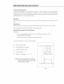
THE PROFESSIONAL ISLAND VENT HOOD
Installation
Guide
MODELS:
IVS40
IVSS2
C(_(_
A MESSAGE TO OUR CUSTOMERS
Thank you for selecting
have developed
appliance
this DCS Professiona!
this Installation
Island
Guide, It contains
for years of safe and enjoyable
Vent Hood. Because of this appfiance!s
valuable
information
on how
unique features
to properly
instal! your
we
new
cooking,
For your convenience, product questions can be answered by a DCS Customer Care Representative by phone:
1-888-281-5698, emaih [email protected], or by mail:
Fisher & Paykd Appliances, Inc
Attention: DCS Customer Care
5900 Skylab Road
Huntingron Beach, CA 92647
www, dcsappliances.com
APPROVED FOR RESIDENTIAL APPLIANCES AND RESIDENTIAL USE ONLY.
PLEASE READ ENTIRE INS TRUCTIONS BEFORE PROCEEDING,
Ins taltation
m us t comply
with all local codes,
WARNING
If the information
in this manual is not fallowed exactly, a fire or explosion
may result causing property damage, personal injury or death. Do not store or
use gasoline or other flammable vapors and liquids in the vicinity of this or any
other appfiance.
WARNING
To reduce the risk of injury to persons in the event of a rangetop
observe the following:
Turn burner off first. Smother flames with a close-fitting
lid, cookie sheet, or metal tray. Be careful to prevent
go out immediately
flaming
pan
dishcloths
ONLY if:
grease fire,
evacuate
- You may
be burned.
or towels - a violent
steam
2) The fire is small and contained
is being
Never pick up a
DO NOT USE WATER, including
explosion
wet
will result. Use an extinguisher
1) You know you have a Class ABC extinguisher,
how to operate it.
3) The fire department
burns. If the flames do not
and call the fire department.
and you already
know
in the area where it started.
called.
4) You can fight the fire with your back to an exit.
Z_
SAFETY WARNING:
Turn off power drcuit at service panel and lock out panel, before wiring
appliance.
Requirement:
120 V AC, 60 Nz. 15 A Branch Circuit
PLEASE RETAIN THIS MANUAL
FOR FUTURE REFERENCE,
this
A MESSAGE TO OUR CUSTOMERS
FOR YOUR SAFETY
If You Smell
Gas:
t Do not try to light any appliance.
t Do not touch any electrical switch; do not use any phone in your building.
l Immediately
callyour gas supplier from a neighbor's phone. Follow the
gas supplier's instructions.
l If you cannot reach your gas supplie_ call the fire department.
[] Installation
and service must be performed
by a qualified installer, service
agency or the gas supplier
TABLE OF CONTENTS
SAFETY PRACTICES ......................................................................................................................................................
3-4
PARTS ........................................................................................................................................................................................
s
BEFORE INSTALLING
HOOD .................................................................................................................................
6-8
INSTALLATION ...............................................................................................................................................................
9-16
HOW TO OBTAIN
WARRANTY
SERVICE ........................................................................................................................................
17
...................................................................................................................................................................
18-19
SAFETY PRACTICES AND PRECAUTIONS
CAUTION:
For general ventilating
materials
Z_
use only. Do not use to exhaust hazardous
or explosive
or vapors.
WARNING:
To reduce the risk of a range top grease fire:
A. Never leave surface units unattended at high settings. BoHovers cause smoking
spHHovers that may ignite. Heat oH showily on How or medium settings.
B. AHways turn venthood "ON" when cooking at high heat or when flambeing
Suzette, Cherries Jubilee, Peppercorn Beef FHambe').
and greasy
foods (i.e. Crepes
C. CHean ventiHating fans frequentHy. Grease shouHd not be aHHowedto accumuHate on fan or fiHter.
D. Use proper pan size. AHways use cookware
Make-Up
window,
air may be necessary to prevent
appropriate
air flowing
down
chimney,
or through
unsealed
door,
or fireplace opening.
Z_
WARNING:
To reduce the risk of fire, electrical
following guidelines.
A,
for the size of the surface unit.
Use this unit only in the manner intended
the manufacturer.
shock, or injury
by the manufacturer.
to persons, observe the
If you have questions, contact
B, Before servicing or cleaning the unit, switch power offat service pane[ and Hockservice pane[
disconnecting
means to prevent power from being switched on accidentally. When the service
disconnecting
means cannot be locked, securely fasten a prominent warning device, such as a
tag, to the service panel.
C. Installation and electrical wiring must be performed
all applicable codes & standards, including fire-rated
by qualified personnel
construction.
in accordance
with
D. To prevent backdraffing,
sufficient air is needed to maintain proper combustion
and safe
exhausting of gases through the flue (chimney) of fuel burning equipment.
Follow the heating
equipment
manufacturers
guideline and safety standards such as those published by the
National Fire Protection Association (NFPA) and the American Society for Heating, Refrigeration
and Air Conditioning
Engineers (ASHRAE),and the local code authorities.
E. Use caution when cutting or drilling
and other hidden utilities.
into walls or ceilings as not to damage
electrical
wiring
SAFETY PRACTICES&
z_
WARNING:
To reduce the risk of fire and to properly
exhaust
outside. Do not vent exhaust air into spaces
within
air, be sure to duct air to
walls or ceiling, nor into
attics, crawl spaces, or garages.
NOTE: Unit MUST be vented to the outside of the building.
IMPORTANT: Refer to ducting
z_
information
supplied
in this manual
WARNING:
To reduce the risk of electrical shock or injury to persons, all vent hoods must
be installed with ventilators that have been approved for use with the hood.
//_
WARNING:
To reduce the risk of fire, use on!y metal duct work.
HnstaHthis hood in accordance
with aH requirements
specified.
WARNING:
To reduce the risk of
external
fire or
electric shock, do not use this hood with any
solid state speed control
device.
WARNING:
To reduce the risk of injury to persons in the event of a rangetop
observe the following:
Turn burner off first. Smother flames with a close-fitting
lid, cookie sheet, or metal tray. Be careful to prevent
go out immediately
flaming
evacuate
or towels
- a violent
steam
2) The fire is small and contained
Never pick up a
DO NOT USE WATER, including
explosion
wet
will result. Use an extinguisher
1) You know you have a Class ABC extinguisher`
how to operate it.
3) The fire department
burns. If the flames do not
and call the fire department.
pan - You may be burned.
dishcloths
ONLY if:
grease fire,
and you already know
in the area where
it started.
is being called.
4) You can fight the fire with your back to an exit.
Z_
WARNING:
To reduce the risk of fire, electrical shock, or injury to persons, the Island Hood
(IV540/521 must be installed
separate
with the chimney structure
box. Custom parts cannot be substituted.
(IVCKI supplied
in the
PARTS INCLUDED WITH YOUR HOOD
n Hood canopy assembly
n MetaH transition
with light bulbs installed.
with back draft dampers
m Use & Care/HnstaHHation Hnstructions
n FHters (quantity
depending
on modeH and size)
n Screws
n HntegraHMowers
n 4 side baffHe trims (HVS52onHy)
m BaffHefiHter paneH
PARTS NOT INCLUDED WITH YOUR HOOD
m Duct tape
n 1/2" conduit
m Wire nuts
m Hood chimney structure and duct covers.Those
HVCK,which must be ordered separateHy.
items are incHuded with accessory kit modeH
BEFORE INSTALLING HOOD
1. For the most efficient
air flow exhaust, use a straight
run or as few elbows as possible.
CAUTION:
Vent unit to outside of building
only.
2. Two people are necessary for installation.
3. The hood is fitted with screws suitable for most surfaces.Consult
a qualified
installer.Check
if they
perfectHy fit with your ceiling.
4. Do not use flex ducting.
5. COLD WEATHER installations
should have an additional
back flow of cold air and a nonmetallic
atures as part of the ductwork.
thermal break.
The break should
house.
6. Hood installation
height
of capturing
cooking
is inconvenient.
8. Make up air: Local building
requirements
to minimize
of outside
temper-
wail) of the
portion
Lower installation
of the
heights
odors, grease, and smoke. These hoods have been
models
an installation
Taller people may find a 30"
height
between
30"and 36'.'
RGS-364GL or CS-364GL, the [VS52 mode[
codes may require the use of Make-Up Air Systems when using Ducted
CFM varies from
in your area.
installed
enters the heated
is the user's preference.
DCS recommends
Systems greater than specified
The specified
damper
conduction
be on the cold air side (outside
heights 30" and above the cooktop/ranges.
7. For installation
over DCS range and cooktop
venthood is recommended.
Ventilation
should
height above cooktop/range
for installation
installation
The damper
backdraff
break to minimize
be as chose as possible to where the ducting
will[ improve the efficiency
approved
thermal
locale
CFM of air movement.
to locale. Consult
your
HVAC professional
for specific
BEFORE iNSTALLiNG HOOD
TYPICAL INSTALLATION
A typka[
hood
installation
is shown
below
in Figure
accessory kit, the hood can be instaHHed at a height
ranging
from 8-J/2 to 10 feet. HnstaHHatonsoutside
quHified instaHHerfor a custom framing
1. When
installed
with
of 30" to 36" in kitchens
this range wHHrequire
the HVCKchimney
with ceiling
custom framing.
heights
ConsuHt a
soHution.
DUCTING
Provide a 10" Round Duct. Ducting
tions.
run cannot exceed 40 feet, incHuding aHHowance for eHbows/transi-
ELECTRICAL
HnstaHH
a 1/2"conduit
from the service paneH Hong enough
to reach the hood once it is instaHHed.
Power suppHy must be rated for 120V 60Hz, 15 amps (minimum).
INSTALLATION
HEIGHT CALCULATIONS
See Figure 1.
a) SeHecta hood instaHHation height C that is comfortabHe for the user. (30"to 36"
recommended, 30" minimum).
b) CaHcuHatechimney
Save this calculation
cover height E using fomruHa bellow.
for use later in the installation.
A=
Kitchen CeiHing Height
B=
Counter
C=
HnstaHHationHeight of Hood.
D=
Canopy Height = 13"
E=
Chimney cover height = A-
Height (36" standard)
B-C-
D
A
C
NOTE: Chimney cover height can be adjusted
from 24-1/'2" to 35" to meet your desired
hood installation
height.
h
FfG. 1
BEFORE INSTALLING HOOD
CEILING PREPARATION
Installing
supports
above ceiling
drywall.
NOTE: Take into consideration
NOTE: The following
the hood
steps pertain
depth; some
models
to hood installation
model IVCK. Other installations
installer.
may require
are much deeper
than the cooktop.
using chimney structure/duct
custom
framing,
etc. Consult
1. Mark center lines of cooktop or range on ceiling above. Use
centerHines marked on ceiling to position the mounting
tempHate. Location of front arrow on the tempHate must point
towards front of cooking surface. Mark mounting holies
indicated on the tempHate.
2. Remove and save template.
Cut and remove ceiling drywall.
Install suitable length 2" x 4" lumber between joists to provide
chimney
mounting
dimensions
points as shown in Fig. 2. Use template
for
and required clearance,
Make sure to affix the added lumber firmly and level.Consult
a
professional
is
unique.
if you
have difficulties
Consult template
or your
installation
and Fig.2.
IMPORTANT:
The ceiling structure
(joists and lumbers)
must be capable of supporting
of the hood (approximately
range
hood
and
the weight
110 tbs for 40"
143 Ibs for 52" range
hood) and any inadvertent
loads.
user contact
3. DUCT INSTALLATION
For IVS-52: Install 10"exhaust
duct and extend length
E minus 4-5/8" (E - 4-5/8") from ceiling.
See Fig. 1. Do not use duct smaller than specified.
4. Install 1/2" electrical
and extend length
conduit
in location
E minus 3-1/8"
(E - 3-1/8") from ceiling (use formula
5. Install drywall
6. Tape
template
marked on template
in Fig. 1).
around duct and conduit;then
in
Step 1. Mark locations
place
using
of mounting
refinish ceiling.
center[ines
marked
in
points. Remove template.
FIG,2
cover kit
a qualified
HOOD INSTALLATION
1. Adjust chimney
mounting
structure
to E + 3/8" dimension
caHcuHation on page 7. Use 2 screws per attachment
2. To install Chimney
Structure
as determined
in installation
to ceiling, use a 10mm or adjustable
wrench
or fiat head screwdriver.
a. DdH pilot holies into ceiling at fixing
points as determined in Step 6 under
Ceiling Preparation (Pg. 8).
b. Screw the 4 Hag screws provided
Fig. 4, do not tighten compHeteHy).
c. Attach mounting
(see
structure to joists with
the 4 Hagscrews provided. (see Rg.4,
keep 10" duct inside structure).
ATTENTION: Junction
Box on the chimney
structure should be oriented
side when fedng
d. Tighten
to the right
the front of the cooktop.
the 4 lag screws, see Fig.4.
Junction
Box
FIG°3
Colin(
Fixing
Leg _
screw
point
_<_
10" Duct
height
Heg,see Fig. 3.
_
FIG.4
INSTALLATION
3.
Assembly of the lO"Transition.
The transition
supplied
with the hood mounts to the top
of the hood, Figure 5.
a.
Duct
Transition
PHacethe transition piece over the hood exhaust
and secure with 4 screws provided.
b. Duct tape connection
hood.
c.
between
transition
and
Remove tape hoHding damper.
Check that the screws on bottom
of chimney
structure
are partiaHHyscrewed into pHace;these will[ serve to hang
FIG.5
and fix the canopy.
5.
6.
If already mounted
in place remove a[[ grease riflers,
Back out the hanging
chimney
structure
Lift the canopy
screws on the bottom
of the
to 1/4" gap.
up to the chimney
support.
Carefully
align the canopy keyhole to the screws on the
chimney
support.
Slide the hood to engage the keyhole slots.See Fig.6.
Tighten screws securely (from inside the canopy). Fix
canopy to structure with 4 screws from inside the
FIG.6
canopy. See Fig. 7.
Make final angular
fixing
adjustment
to unit at ceiling if necessary, then finish installation
screws. See Fig. 8.
fixing screw
FIG.7
FIG.8
10
adding two
9,
Ducfing:
There should be no more than 1"
gap between canopy
transition
ducting. Adjust starting
ducts. Tighten
and house
coHHarover both
coHHar.Fasten duct with
screws and tape per code. Screws must not
hamper the damper. See Fig. 9.
INTEGRAL VENTILATOR INSTALLATION
(see Fig. 10 to 11)
FIG. 9
1.
The Hntegra[ ventilator
can be mounted
to
discharge
air towards the ceiling. So motor
connector
may be [ocated frontwards.
From the inside of the hood, slip motor into
the bracket on the [eft.
Rotate motor upwards
until it snaps into the
I
/
spring dip on the right.
Bracket
Secure the motor to the hood with the
machine screw and lock washer,
Hug connector
into the motor, Fig. 11.
From Control
Pane[
Spring Clip
Integral
Bracket
Motor
ventilator
for 40" Hood
Connector
Fixing
point
Fixing
point
support
Spring Clip
FIG. 10
Motor
connector
FIG. 1 1
11
INSTALLATION
Snap the centra[ baffJe tinter pane[ into the pJace so the both rainsengage with side pins on both
sides of hood. Drive 2 screws (1 on each side ) through
Snap four-side
separately
4.
baffJe rifler pane[ hone to hood. See Fig. 12.
baffNe trim to hood (4 pins engage each side trim).The
(for [VS52 only). See Fig. 13.
Install a[[ baffle riflers as per Use and Care Manual instructions.
Fig. 12
Fig. 13
12
baffNe trims are suppNied
wmRmNGTO POWER SUPPLY
/_
WARNING:
Turn off power circuit at the service panel before wiring this unit.
120 VAC, 15 Amp circuit required.
1.
Remove j-box cover as shown in Fig. 14.
2.
Remove the knockout
3.
Run 3 wires; bHack,white and green (#14 AWG) in 1/2" conduit
4.
Connect
and install[ the strain reHief (conduit)
connector
(1/2") in junction
box.
from service pane[ to junction
bHackwire from service pane[ to bHack or red in junction
box.
box, white to white and green
to green-yeHHow. See Fig. 14.
5.
CHosejunction
box cover.
6.
Hug cane at the top of the hood into the junction
7.
Check all[ Hight buHbs to make sure they are secure in their sockets, then turn power on in service
pane[ and check [ights and bHower operation
and riflers.
box connector.
per Care & Use manua[ and install[ drip tray support
1/2 '+
Conduit
Junction
[Box
From Control
Panel
FIG. 14
13
FINAL ASSEMBLY
For final Chimney
Cover installation,
NOTE: Overtightening
1.
DO NOT USE ELECTRIC SCREW DRIVER.
screws can deform metal.
Hnsta[[the cage nuts from inside the rectangular
slots supplied
with top and bottom
duct covers,
See Fig, 15.
A total of 14 nuts must be fitted.
Duct
\
/
cover
Top section
Duct
uct cover
Top
_p section
Duct cover
Dm section
Duct
FIG. 15
14
INSTALLATION
2.
Install the two brackets to the chimney
side.
3.
Join the two top sections of the duct cover.
Screw the two sections together
joining
4.
structure
supplied
with the kit by using one screw each
with 8 screws (4 each side- see the top view in Fig. ] d for
the two sections).
Install the top duct cover assembly to the bracket, near the ceiling, with two screws (one each
side).
Fix to the top
"_
Bracket
Bracket
I
Drive a #! 0 x 2-1/4"
screw into wood
framing
above
ceiling.Thisscrew
supports the load of
the upper chimney
duct cover.One
screweachside.
- - -._
Top Duct
assembly
Diagram
_®®®®®®®®®®®®®®®®®®®®®®®®®®_
FIG. 16
15
Join the two bottom
sections of the duct cover which covers the chimney
screws, (3 each side, see Fig. 17 for the phn diagram
Hnsert the bottom
structure.
structure
using 6
for joinincj the two sections).
section of the duct cover in its seat so that it compHeteHy covers the chimney
Hnsta[[the 4 supplied trims for duct cover channels to cover the fasteners of the bottom duct
covers. (CAUTHON!THE BOTTOM FLUE TRHMSARE THE NARROWER AND SHALLOWER ONES).
The wider and deeper trims are those used for the top flue, and must be cut to size.
ff necessary, slightly
expand the trims to ensure their adherence
8.
Turn the power on again at the electrical
9.
Make sure to leave this
to the flue.
pane[ and check for correct
hood operation.
manual for the home owner.
Screw
Duct cover
Rear Bottom
section
Duct cover
Front Bottom
section
Bottom Duct
assembly
Diagram
Tabs
FIG+ 17
16
HOW TO OBTAIN SERVICE
BEFORE YOU CALL FOR SERVICE
I Is the circuit
breaker tripped
[] Is there a _ower outage
For warranty
servuce, contact
pHease have the following
or the fuse bHown?
in the area?
DCS Customer
information
Care Representative
at (888) 281-5698,
Before you ca[[,
ready:
[] Mode[ Number
[] Serial Number
[] Date of installation
[] A bdef description
Your satisfaction
of the probHem
is of the utmost importance
to us, Ifa problem
pHease caHH,
write or emaH us at:
Write:
Fisher & Payke[ Appliances, [nc,
Attention: DCS Customer Care
5900 Skyhb Road
Huntington
Beach,CA 92647
emaH: support@dcsapp[h
nces,com
17
cannot be resolved to your satisfaction,
LiMiTED
WARRANTY
When you purchase
a new DCS Ventilation
receive a One year Limited
Limited Warranty
Product for persona[ or consumer
Warranty, covering
on the switches and motor (parts only) for servicing
States, Hawaii,Washington
use you automatically
parts and labor for the entire product,
within
United
D.C and Canada. In Alaska the Limited Warranty, is the same except that you
must pay to ship the Product to the service shop or for the service technician's
Products for use in Canada must be purchased
regulatory
and a Five year
the 48 mainland
through
travel to your home.
the Canadian distribution
channel to ensure
compliance.
If the Product is installed
in a motor vehicle, boat or similar mobile facility, you receive the same One
year Limited Warranty, but you must bring the vehicle, boat or mobile fadiity
to the service shop at your expense or pay, the service technician's
FISHER & PAYKEL UNDERTAKES
Repair without
containing
the Product
travel to the location of the Product.
TO:
cost to the owner either for mateda[ or labor any part of the Product, the serial number
of which appears on the Product, which is found to be defective. In Alaska, you must pay, to ship the
Product to the service shop or for the service technician's
travel to your home.if the Product is installed
in a motor vehicle, boat or similar mobile facility, you must bring it to the service shop at your expense
or pay for the service technician's
defective
travel to the location
part of the Product after a reasonable
of the Product.
number of attempts,
part or the Product, or we may, provide you a fui[ refund
including
installation
This warranty
purchased
provided
If we are unable to repair a
at our option
of the purchase
we may, replace the
price of the Product
(not
or other charges).
extends to the original
for ordinary
purchaser and any, succeeding
single-family
home
by Fisher & Payke[ or its Authorized
use. Ai[ service
owner of the Product for products
under
this Limited
DCS Service Agent during
Warranty
shah be
normal business hours.
HOW LONG DOES THiS LiMiTED WARRANTY LAST?
Our liability
purchase
under this Limited
of the Product
Warranty, for the entire
by the first consumer.
product
Our liability
expires ONE YEAR from the date of
under
this Limited
switches and motor (parts only) expires FIVE YEARS from the date of purchase
first consumer.
Our liability
unwritten
under
warranty,
period as required
any, implied
warranties,
that the Product
by, applicable
the implied
warranty
for the
of merchantability
by, the
(an
is fit for ordinary, use) also expires ONE YEAR (or such longer
law) from the date of purchase of the Product by, the first consumer.
Some states do not allow [imitations
warranties
including
Warranty
of the Product
on how long an implied
warranty
lasts, so this limit on implied
may, not apply to you.
THiS WARRANTY DOES NOT COVER:
A. Service calls that are not related
charged if the problem
to any defect
in the Product. The cost of a service cai[ wii[ be
is not found to be a defect of the Product. For example:
1. Correct fauffy installation
of the Product.
2. Instruct you how to use the Product.
3. Replace house fuses, reset circuit
bulbs.
breakers, correct
house wiring
4. Correct fault(s) caused by the user.
5. Change the set-up of the Product.
6. Unauthorized
modifications
of the Product.
18
or plumbing,
or replace light
7.Noiseorvibration
thatisconsidered
normal,
forexample,
drain/fansounds,
regeneration
noises
oruserwarningbeeps.
8.Correcting
damage
caused
bypests,
forexample,
rats,cockroaches
etc.
B.Defects
caused
byfactorsotherthan:
1.Normaldomestic
useor
2.Useinaccordance
withtheProduct's
UserGuide.
C.Defects
to theProduct
caused
byaccident,
neglect,
misuse,
fire,floodor ActofGod.
D.Thecostofrepairs
carriedoutbynon-authorized
repairers
orthecostofcorrecting
such
unauthorized
repairs.
E.TravelFees
andassociated
charges
incurred
whentheproductisinstalled
inalocationwithlimited
or restricted
access.
(i.e.airplaneflights,ferrycharges,
isolated
geographic
areas).
F.Normalrecommended
maintenance
assetforthintheProduct's
UserGuide.
if youhaveaninstallation
problemcontactyourdealerorinstaller.You
areresponsible
forproviding
adequateelectrical,exhaustingand otherconnectionfacilities.Weare not responsible
for
consequential
orincidental
damages
(thecostofrepairing
orreplacing
otherproperty
damaged
ifthe
Productisdefective
or anyofyourexpenses
caused
if theProductisdefective).
Somestates
do not
allowtheexclusion
or [imitation
of incidental
or consequential
damages,
sotheabove[imitation
or
exclusion
maynotapplyto you.
HOW TO GET SERVICE
Please read your User Guide. if you then have any questions
name of your local DCS Authorized
under this Limited Warrant},,, please contact
to provide
the Product, need the
and wish service
your dealer or call us at:
TOLL FREE1o888o281 5698 or contact
You may be required
about operating
Service Agent, or believe the Product is defective
us through
reasonable
our web site: www.dcsappliances.com.
proof of the date of purchase of the Product before the
Product will be serviced under this Limited Warranty.
COMMERCIAL USE
This warranty applies to appliances
commercial situations.
used in residential
applications;
it does not cover their use in
NO OTHER WARRANTIES
This Limited
regarding
Warranty
is the complete
and exclusive
agreement
any defect in the Product. None of our employees
authorised
to make any addition
Warrantor:
Fisher & Paykel Appliances,
If you need further
or modification
help concerning
between
you and Fisher & Paykel
(or our Authorized
Service Agents) are
to this Limited Warranty.
Inc.
this Limited Warrant},,, please caii us at the above number, or write
to:
Fisher & Paykel Appliances, inc.
5900 Skyiab Road, Huntington Beach,CA 92647
This Limited Warranty gives you specific
from state to state.
legal rights, and you may also have other rights which vary
19
20
A Fisher
& Paykel
Appliances,
Inc
Company
Fisher & Paykel Appliances, Inc.
5900 Bkylab Road, Huntington Beach, CA 92647
Customer Care: 888.28! .5698
Fax: 714.372.7003
www.dcsappliances.com
As product
reserve the
notice.
improvement
is an ongoing
right to change specifications
DCS am@liore constamment
de modifier les specifications
sans aUCUF_preavis.
P/N 17804 Rev. D
Litho in USA 02/2005
process at DCS, we
or design without
ses produits et se r@serve le droit
ou la conception
de ses produits