1
Operator's
GA
E
Manual
TRACTO
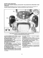
26.0 HP,* 54" Mower
Electric Start
Automatic Transmission
Model No.
917.28947
• EspaSol,#.36
This product has a tow emission engine which operates
differently from previously built engines. Before you start the
engine, read and understand this Owner's Manual,
IMPORTANT:
Read and follow all Safety
Rules and Instructions before
operating this equipment.
For answers to your questions
about this product, Call:
1-800-659-5917
Sears Craftsman Help Line
5 am - 5 pm, Mon - Sat
SEARS, ROEBUCK AND COo, HOFFMAN ESTATES,
Visit our Craftsman website:wwwosears,com/oraftsman
425987
Rev. 2
IL 60179
U.SoA.
*As rated by' the engine manufacturer
Warranty ........................................................
2
Safety Rules ............................................
3
Product Specifications
.............................
6
Assembly!P re-Operation
.........................
8
Operation ...............................................
13
Maintenance
Schedule ........................... 2t
CRAFTSMAN
TWO YEARS
Maintenance ...........................................
2'1
Service and Adjustments ........................ 26
Storage ..................................................
31
Troubleshooting
.....................................
32
Sears Service ............................ Back Cover
FULL WARRANTY
ON RIDING
EQUIPMENT
When oPerated and maintained according to all supplied instructions, if this riding equipment
fails due to a defect in material or workmanship within two years from the date or purchase,
call 1-800-4-MY-HOME®
to arrange for free repair.
Also, when operated and maintained
according to all supplied instructions,
Warranty will
also cover defects in material and workmanship
of the Frame and Front Axle for five years
from the date of purchase
This warranty
pay for:
•
•
covers
ONLY defects
in material
and workmanship.
Sears
Expendable
items that become worn during normal use, including
blades, spark plugs, air cleaners, belts, and oil filters.
Standard maintenance
servicing, oil changes, or tune-ups.
Tire replacement
or repair caused
thorns, stumps, or glass.
.
Tire or wheel replacement
operation or maintenance.
°
Repairs necessary
because of operator abuse, including but not limited to damage
caused by towing objects beyond the capability of the riding equipment,
impacting
objects that bend the frame or crankshaft, or over-speeding
the engine.
°
Repairs necessary because of operator negligence, including but not limitedto, electrical
and mechanical damage caused by improper storage, failure to use the proper grade
and amount of engine oil, failure to keep the deck clear of flammable debris, or failure to
maintain the riding equipment according to the instructions contained in the operator's
manual.
•
Engine (fue! system) cleaning or repairs caused byfuel determined to be contaminated
or
oxidized (stale). In general, fuel should be used within 30 days of its purchase date.
-
Normal
or repair resulting
Roebuck
warranty
coverage
objects,
such as nails,
wear, accident,
or improper
or product label replacement.
is void if this product
is ever used for
only while this product is within the United States°
This warranty gives you specific
vary from state to state°
Sears,
from normal
and wear of the exterior finishes,
All riding equipment and battery
commercial
or rental purposes.
This warranty applies
from outside
but not limited to
.
deterioration
by punctures
will NOT
legal rights, and you may also have other rights which
and Co., Hoffman
Estates,
2
IL 60'179
_DANGER: This cutting machine is capable of amputating hands and feet and
throwing objects. Failure to observe the following safety instructions could result
m serious injury or death,
,_WARNING:
in order to prevent accidental starting when setting up, transporting,
adjusting or making repairs, always disconnect spark plug wire and place wire where
it cannot contact spark plug.
•
Neverdirect
discharged materialtoward
anyone.
Avoid discharging
material
against a wall or obstruction.
Material
may ricochet back toward the operator.
Stop the blades when crossing gravel
surfaces.
,_WARNING:
Do not coast down a hill in
neutral, you may lose control of the tractor.
•
Do not operate machine without the entire grass catcher, discharge
chute, or
other safety devices in place and working,
Slow down before turning.
Never leave a running machine unattended.
Always turn off blades, set
parking brake, stop engine, and remove
keys before dismounting.
Disengage
blades when not mowing°
Shut off engine and wait for all parts to
come to a complete stop before cleaning
the machine, removing the grass catcher,
or unclogging the discharge chute.
Operate machine only in daylight or good
artificial light.
Do not operate the machine while under
the influence of alcohol or drugs.
Watch for traffic when operating near or
crossing roadways.
Use extra carewhen ioadingorunloading
the machine into a trailer or truck.
_WARNING:
Tow only the attachments
that are recommended
by and comply with
specifications
of the manufacturer
of your
tractor. Use common sense when towing.
Operate only at the lowest possible speed
when on a slope. Too heavy of a load, while
on a slope, is dangerous.
Tires can lose
traction with the ground and cause you to
lose control of your tractor.
•
.
•
_WARNING:
Engine exhaust, some of
its constituents, and certain vehicle components contain or emit chemicals known to the
State of California to cause cancer and birth
defects
or other reproductive
•
•
harm.
•
_WARNING:
Battery posts, terminals and
related accessories
contain lead and lead
compounds, chemicals known to the State of
California to cause cancer and birth defects
or other reproductive
harm_ Wash hands
after handling.
I, GENERAL
•
°
,
,
•
•
•
.
°
•
OPERATION
Read, understand, and followailinstructions on the machine and in the manual
before starting.
Do not put hands or feet near rotating
parts or under the machine. Keep clear
of the discharge opening at all times_
Only allow responsible
adults, who are
familiar with the instructions, to operate
the machine.
•
°
Clear the area of objects such as rocks,
toys, wire, etc., which could be picked
up and thrown by the blades.
Be sure the area is clear of bystanders
before operating° Stop machine if anyone
enters the area.
Never carry passengers.
Do not mow in reverse unless absolutely
necessary. Always look down and behind
before and while backing.
3
AIwaysweareye
protection when operating machine.
Data indicates that operators,
age 60
years and above, are involved in a large
percentage of riding mower-related
injuries. These operators should evaluate
their ability to operate the riding mower
safely enough to protect themselves and
others from serious injury.
Follow the manufacturer's
recommendation for wheel weights
or counterweights.
Keep machine free of grass, leaves or
otherdebris build-up which can touch hot
exhaust / engine parts and burn. Do not
allow the mower to plow leaves or other
debris which can cause build-up to occur. Clean any oil or fuel spillage before
operating or storing the machine. Allow
machine to cool before storage.
g. SLOPE OPERATION
•
Slopes are a major factor related to loss of
control and tip-over accidents, which can
result in severe injury or death. Operation
on all slopes requires extra caution. If you
cannot back up the slope or if you feel uneasy
on it, do not mow it.
•
Mow up and down slopes, not across.
• Watch for holes, ruts, bumps, rocks, or
other hidden objects.
Uneven terrain
could overturn the machine.
Tall grass
can hide obstacles.
°
•
•
•
•
-
•
•
Choose a low ground speed so that you
will not have to stop or shift while on the
slope°
Do not mow on wet grass. Tires may lose
traction.
Always keep the machine in gear when
going down slopes. Do not shift to neutral
and coast downhill.
Avoid starting, stopping, or turning on a
slope° Ifthetires tosetraction, disengage
the blades and proceed slowly straight
down the slope.
Keep all movement on the slopes slow
and gradual°
Do not make sudden
changes
in speed or direction, which
could cause the machine to roll over.
Use extra care while operating machine
with grass catchers or other attachments;
they can affect the stability of the machine. Do no use on steep slopes.
Do not try to stabilize the machine by
putting your foot on the ground.
Do not mow near drop-offs,
ditches,
or embankments_
The machine could
suddenly roll over if a wheel is over the
edge or if the edge caves in o
IV, TOWING
•
•
°
•
°
SAFE HANDLING
•
•
OF GASOLINE
To avoid personal injury or property damage, use extreme care in handling gasoline.
Gasoline is extremely flammable
and the
vapors are explosive.
Extinguish all cigarettes, cigars, pipes,
and other sources of ignition_
•
Use only approved gasoline container.
•
Never remove gas cap or add fuel with
the engine running. Allow engine to coo!
before refueling.
•
Neverfuel
the machine indoors.
° Never store the machine orfuelcontainer
Tragic accidents can occur if the operator
is not alert to the presence
of children.
Children are often attracted to the machine
-
Tow only with a machine that has a hitch
designed for towing. Do not attach towed
equipment except at the hitch point.
Followthemanufacturer'srecommenda_
tion for weight limits for towed equipment
and towing on slopes.
Never allow children or others in or on
towed equipment.
On slopes,theweight
of the towed equipment may cause loss of traction and loss
of control.
Travel slowly and allow extra distance to
stop.
V. SERVICE
II!, CHILDREN
and the mowing activity.
that children will remain
saw them.
Never carry children,
even with the
blades shut off. They may fall off and
be seriously injured or interfere with safe
machine operation° Children who have
been given rides inthe past may suddenly
appear in the mowing area for another
ride and be run over or backed over by
the machine.
Never allow children to operate the machine.
Use extra care when approaching
blind
corners, shrubs, trees, or other objects
that may block your view of a child.
Never assume
where you last
•
Keep children out of the mowing area
and in the watchful care of a responsible
adult other than the operator.
Be alert and turn machine off if a child
enters the area.
Before and while backing, look behind
and down for small children.
•
4
where there is an open flame, spark,
pilot light such as on a water heater
other appliances_
Never fill containers inside a vehicle
or
or
or
on atruck or trailer bed with plastic liner.
Always place containers on the ground
away from your vehicle when filling.
Remove gas-powered
equipment from
the truck or trailer and refuel it on the
ground_ If this is not possible, then refuel
such equipmentwith
a portable container,
rather than from a gasoline dispenser
nozzle.
• Keepthe nozzlein contactwiththe rim
of the fuel tank or containeropeningat
alltimesuntilfuelingis complete.Do not
use a nozzlelock-opendevice.
, lffuel isspilledonclothing,changeclothing immediately.
• Neveroverfillfueltank.Replacegascap
andtightensecurely.
•
•
.
GENERALSERVICE
•
•
•
,
.
°
•
•
°
Never operate
machine
in a closed
area.
Keep all nuts and boltstight to be surethe
equipment is in safe working condition.
Nevertamperwithsafetydevices.Check
their proper operation regularly.
Keep machine free of grass, leaves, or
other debris build-up.
Clean oil or fuel
spillage and remove anyfuel-soaked
debris. Allow machine to cool before storing.
•
•
•
Do not mow in reverse unless absolutely
necessary° Always look down and behind
before and while backing.
Never carry children,
even with the
blades shut off. They may fall off and
be seriously injured or interfere with safe
machine operation_ Children who have
been given rides in the past may suddenly
appear in the mowing area for another
ride and be run over or backed over by
the machine_
Keep children out of the mowing area
and in the watchful care of a responsible
adult other than the operator_
Be alert and turn machine off if a child
enters the area.
•
Nevercarry
•
Before and while backing, look behind
and down for small children°
Mow up and down slopes (15 ° Max), not
across.
Choose a low ground speed so that you
will not have to stop or shift while on the
slope°
Avoid starting, stopping, or turning on a
slope, If the tires lose traction, disengage
the blades and proceed slowly straight
down the sloper
If machine
stops while going uphill,
disengage blades, shift into reverse and
back down slowly,
Do not turn on slopes unless necessary,
and then, turn slowly and gradually
downhill, if possible°
•
o
•
•
•
5
If you strike a foreign object, stop and
inspect the machine. Repair, if necessary,
before restarting.
Never make any adjustments or repairs
with the engine running.
Check grass catcher components and the
discharge chute frequently and replace
with manufacturer's recommended parts,
when necessary.
Mower blades aresharp. Wrapthe blade
or wear gloves, and use extra caution
when servicing them_
Checkbrakeoperationfrequently.
Adjust
and service as required_
Maintain orreplacesafetyandinstruction
labels, as necessary°
Be sure the area is clear of bystanders
before operating. Stop machine ifanyone
enters the area°
passengers.
PRODUCT
SPECIFICATIONS
Gasoline Capacity
and Type:
4 Gallons
Unleaded Regular
Oil Type
(API-SG-SL):
SAE 10W30(above 32°F)
SAE 5W30(below 32°F)
Oil Capacity:
Wi Filter:
Spark
Champion RC12YC
(Gap: .030")
Plug:
Congratulations on making a smart purchase.
Your new Craftsman@ product is designed
and manufactured
for years of dependable
operation. But like all products, it may require
repair from time to time. That's when having
a Repair Protection Agreement can save you
money and aggravation.
64 oz
Ground Speed
Forward:
Reverse:
Charging System:
15 Amps
Battery:
Amp!Hr:
Min. CCA:
Case size:
Blade Bolt
REPAIR
PROTECTION
AGREEMENTS
Purchase a Repair Protection Agreement
now and protect yourself from unexpected
hassle and expense
0 - 7.8
0 - 2.1
Here's what's
@ 3600 RPM
28
230
U1R
45-55 Fro Lbs.
in the Agreement:
•
Expert service by our 12,000 profesional
repair specialists.
•
Unlimited service and nochargeforparts
and labor on all covered repairs.
Product replacement
product can't be fixed.
Torque:
CONGRATULATIONS
on your purchase of
a new tractor. It has been designed, engineered and manufactured to give youthe best
possible dependability
and performance.
Should you experience any problem you cannot easily remedy, please contact a Sears or
other qualified service center. We have competent, well-trained representatives
and the
proper tools to sen,ice or repair this tractor.
Please read and retain this manual. The
instructions
wilt enable you to assemble
and maintain your tractor properly. Always
observe the "SAFETY RULES'L
CUSTOMER
included
if your
covered
Discount of 10% from regular price of
service and service-related
parts not
covered by the agreement; also, 10% off
regular price of preventive maintenance
check.
Fast help by phone - phone support
from a Sears representative
on products
requiring in-home repair, plus convenient
repair scheduling.
Once you purchase
the Agreement,
a
simple phone call is all that it takes for you
to schedule service_ You can call anytime
day or night, or schedule a service appointment online.
RESPONSIBILITIES
• Read and observe the safety rules_
• Follow a regular schedule in maintaining,
caring for and using your tractor.
• Follow the instructions
under "Maintenance" and "Storage"
sections
of this
owner's manual,
Sears has over 12,000 professional
repair
specialists,
who have access to over 4°5
million quality parts and accessories. That's
the kind of professionalism
you can count on
1o help prolong the life of your new purchase
for years to come. Purchase your Repair
Protection Agreement today!
_kWARNING:
This tractor is equipped with
an internal combustion engine and should not
be used on or near any unimproved forestcovered, brush-covered
or grass-covered
land unless the engine's exhaust system is
equipped with a spark arrester meeting applicable local or state laws (if any). If a spark
arrester is used, it should be maintained
in
effective working order by the operator.
In the state of California the above is required
by law (Section 4442 of the California Public
Resources Code). Other states may have
similar laws. Federal laws apply on federal
lands° A spark arrester for the muffler is
available through your nearest Sears service
center (See REPAIR PARTS manual).
Some limitations
and exclusions apply,
For prices and additional information call
1-800-827-6655,
SEARS
INSTALLATION
SERVICE
For Sears professional
installation of home
appliances,
garage door openers,
water
heaters, and other major home items, in the
U.S.A. call 1-800-4-MY-HOME®
6
Mower
(1) Wheel
Front
Wheel
Q
__
(1) Locknut
_]
(1) Shoulder
3/8416
B0lt_
(1) t-1/40_D,
Washer
Mower
(1) Front Link
(5)
_L,
Large Retainer
Springs o_7/16
(t) 3/40.Do
Washers
(1) Anti-Swar
(2) Small Retainer
Springs - 5/!6
(5) 1-3/1 60.D.
Washers
(2) Rear Lift Link
Assemblies
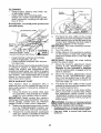
Slope
(2) Keys
(1) Oil Drain Tube
For Future Use
411111
Sheet
Bar
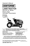
Your new tractor has been assembled at the factory with exception of those parts left
unassembled
for shipping purposes.
To ensure safe and proper operation of your tractor
all parts and hardware you assemble must be tightened securely.
Use the correct tools
as necessary to ensure proper tightness_
TOOLS REQUIRED
FOR ASSEMBLY
A socket wrench
easier. Standard
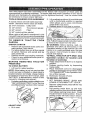
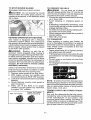
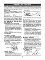
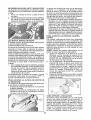
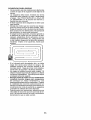
2.
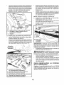
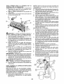
Lift up adjustment lever (A) and slide seat
until a comfortable
position is reached
which allows you to press clutch/brake
pedal all the way down°
3. Release lever to lock seat in position.
set will make assembly
wrench sizes are listed°
(2) 7/16" wrenches
Utility knife
(1) 1/2" wrench
Tire pressure
(1) 3/4" wrench
Pliers
(1) 3/4" socket w/drive
gauge
ratchet
When right or left hand is mentioned in this
manual, it means when you are in the operating
position (seated behind the steering wheel).
TO
REMOVE
CARTON
UNPACK
•
,
•
TRACTOR
NOTE: You may now roll your tractor off the
skid. Follow the appropriate instruction below
to remove the tractor from the skid.
FROM
CARTON
WARNING:
Before starting, read, understand and follow all instructions
in the
Operation section of this manual° Be sure
tractor is in a well-ventilated
area. Be sure
the area in front of tractor is clear of other
people and objects.
Remove all accessible loose parts and
parts cartons from carton o
Cut along dotted lines on all four panels
of carton. Remove end panels and lay
side panels flat.
Remove mower and packing materials.
Check for any additional loose parts or
cartons and remove.
BEFORE
REMOVING
FROM SKID
TO CHECK
TO ROLL
Operation
position.
NOTE: If this battery is put into service after
month and year indicated on label (label is
located between terminals) charge battery
for minimum of one hour at 6-10 amps. (See
"BATTERY" in Maintenance
section of this
manual for charging instructions).
*
(See
and
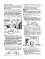
TO INSTALL MOWER
1. SET PARKING
BRAKE LEVER AND
LOWER ATTACHMENT
LIFT LEVER
For batteryand batterycableinstallationsee
"REPLACING
BATTERY" in the "Service
and Adjustments" section in this manual.
Label
ADJ UST S EAT
I.
OFF SKiD
for location
function
of controls)
1. Raise attachment lift lever to its highest
position.
2. Release parking brake by depressing
brake pedal.
3. Place freewheel
control in disengaged
position to disengage transmission
(See
"TO TRANSPORT"
in the Operation section of this manual).
4. Roll tractor forward off skid.
TRACTOR
BATTERY
1o Lift hood to raised
TRACTOR
section
Sit in seat.
8
•
Depress clutch/brake
down and hold.
pedal all the way
•
Pull parking brake lever up and hold,
release pressure from clutch/brake pedal,
then release parking brake lever. Pedal
should remain in brake position. Ensure
parking brake will hold tractor secure.
,_CAUTION:
Lift lever is spring loaded.
Have a tight grip on lift lever, lower it slowly
and engage in lowest position.
Lift lever is
located on left side of fender.
3_
•
Li_
Lever
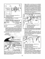
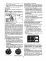
2o ASSEMBLE
TURN STEERING
WHEEL
POSITION MOWER
Turn steering wheel to the left as far as it
will go and position mower on right side of
tractor with deflector shield (Q) to the righL
Front
FRONT
(W) TO FRONT
GAUGE
LEFT AND
ire
WHEEL
OF MOWER
Back
Transaxle
Q_ Deflector Shield
-®
H,
Wo
X,,
Y'.
Z.
Front Mower Bracket
Front Gauge Wheel
Shoulder Bolt
1-1/40.Do Washer
3/8-16 Locknut
Ao
Bo
Co
Do
E.
E
Ho
Mower Side Suspension Arms
Retainer Spring
Rear Lift Link(S)
Right Side Rear Mower Bracket
Front Lift Link Assembly
Front Suspension Bracket
Front Mower Bracket
4,
SLIDE MOWER
UNDER
TRACTOR
•
Bring belt forward and check belt for
proper routing in all mower pulley grooves°
NOTE: Be sure mower side suspension
arms (A) are pointing forward before sliding
mower under tractor.
9
•
Slide mower under tractor
centered under tractor°
I,.
K.
L
M
Q.
S.
W_
Left Side Rear Mower Bracket
Belt Tension RGd
Locking Bracket
Engine Clutch Pulley
Deflector Shield
Anti-Sway Bar
Front Gauge Wheel
until
it is
.
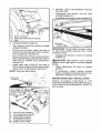
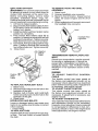
.
Pivot the integrated washer end of antisway bar (S) towards mower deck bracket
on right side of mower. Insert integrated
washer end of bar into hole in rear mower
bracket (D). Move mower as needed to
insert integrated washer end of bar into
rear mower bracket (D).
Secure with small washer and small
retainer spring as shown.
A. Mower Side Suspension Arms
Q. Deflector Shield
5, INSTALL ANTI-SWAY
(IF EQUIPPED)
ANTI-SWAY
Towards
Transaxle
BAR (S)
BAR
(S)
Towards
Mower
Deck
90 ° End
Integrated Washer End
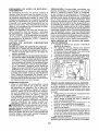
6. ATTACH
•
From right side of mower, first insert
90 ° end of anti-sway bar (S) into hole in
transaxle bracket (T), located near left
rear tire in front of transaxle.
NOTE: Flashlight
Anti-Sway
Bar (S)
ARMS
'_
r
SIDE SUSPENSION
(A) TO CHASSIS
°
Position front hole in side suspension arm
(A) over pin on outside of tractor chassis
and secure with large washer and large
retainer spring (B).
°
Repeat on opposite
may be helpful.
i)
i I
MOWER
side of tractor,
h
Transaxle Bracket (T)
Located Between Rear Tires
A. Mower Side Suspension Arms
B o Retainer Spring
D. Right Side Rear Mower Bracket
7. ATTACH
Insert rod end of rear lift link (C) into hole
(U) in tractor lift shaft suspension
arm
and pivot link down to mower.
•
Lift rear corner of mower and position slot
in link assembly over pin on rear mower
bracket (D) and secure with large washer
and large retainer spring.
°
Repeat on opposite
NOTE: Depending on model, bracket (T) may
be different than shown but hole for anti-sway
bar will be in same position!location,
10
REAR LIFT LINKS (C)
•
side of tractor.
9
INSTALL BELT ON ENGINE
PULLEY (M)
CLUTCH
o
Disengage
belt tension
locking bracket (L).
(K) from
•
install beltonto
rod
engine clutch pulley (M) o
C, Rear Lift Link(s)
V D, Right
Righ _ Side Rear Mower Bracket
I 'U. Hole
8
ATTACH
•
Turn steering wheel
straight forward,
o
From front of tractor, insert rod end of
front link (E) through front hole in tractor
front suspension
bracket (F),
Move to left side of mower and and insert
•
FRONT
LINK (E)
to position
wheels
IMPORTANT: Check belt for proper routing
in al! mower pulley grooves
and under
mandrel covers,
•
large retainer spring (G) through hole in
front link (E) behind front suspension
bracket (F),
•
Requires
/
Front Link
/
deck lifting.
I
rod (K) on locking
_CAUTION:
Belt tension rod is spring
loaded, Have a tight grip on rod and engage
slowly.
Insert other end of link (E) into hole in
front mower bracket (H) and secure with
washer and small retainer spring (J).
NOTE:
Engage belt tension
bracket (L),
i \'17
.,; I
,
Raise attachment
position°
o
If necessary,
adjust
gauge
wheels
before operating mower as shown in the
Operation section of this manual.
MOWER
DRIVE
lift lever
to highest
BELT INSTALLATION
Follow
procedure
described
in "TO
REPLACE MOWER BLADE DRIVE BELT"
in the "Service and Adjustments"
section of
this manual,
F.
G.
H_
J.
M.
Front Lift Link Assembly
Front Suspension Bracket
Large Retainer Spring
Front Mower Bracket
Small Retainer Spring
Engine Clutch Pulley
11
CHECK
TIRE
PRESSURE
CHECKLIST
The tires on your tractor were over-inflated
at the factory for shipping purposes. Correct
tire pressure is important for best cutting
performance°
• Reducetire pressure to PS1 shown ontires,
Before you operate 'your new tractor, we
wish to assure that you receive the best
performance
and satisfaction
from this
Quality Product.
CHECK
DECK
Please
For best
should be
MOWER"
section of
cutting results, mower housing
properly leveled. See "TO LEVEL
in the Service and Adjustments
this manual.
LEVELNESS
CHECK FOR PROPER
ALL BELTS
POSITION
BRAKE
checklist:
J'
All assembly
instructions
have been
completed.
/" No remaining loose parts in carton.
#f Battery
is properly
prepared
and
charged°
_/Seat
is adjusted comfortably
and tightened securely,
_' All tires are properly inflated. (For ship.,
ping purposes, the tires were overinflated
at the factory).
#f Be sure mower deck is properly leveled
side.oto-side/front-to-rear
for best cutting
results. (Tires must be properly inflated
for leveling).
/
Check mower and drive belts_ Be sure
OF
See the figures that are shown for replacing
motion and mower blade drive belts in the
Service and Adjustments section of this manual. Verify that the belts are routed correctly.
CHECK
review the following
SYSTEM
After you learn how to operate your tractor,
check to see that the brake is operating properly. See"TO CHECK BRAKE" inthe Service
and Adjustments
section of this manual°
they are routed properly around pulleys
and inside all belt keepers.
Cf Check wiring. See that all connections
are still secure and wires are properly
clamped.
_/f Before driving tractor, be sure freewheel
control is in "transmission
engaged"
position (see "TO TRANSPORT'
in the
Operation section of this manual).
While learning how to use your tractor, pay extra attention to the following important items:
Engine oil is at proper level.
_€' Fuel tank is filled with fresh, clean, regular
unleaded gasoline.
_" Become familiar with all controls, their
location and function.
Operate them
before you start the engine.
Be sure brake system is in safe operating
condition.
_"
_f
12
Be sure Operator Presence System and
Reverse Operation System (ROS) are
working properly (See the Operation and
Maintenance
sections in this manual).
It is important to purge the transmission
before operating your tractor for the first
time. Follow proper starting and transmission purging instructions (See "TO START
ENGtN E" and "PURGE TRANSMISSION"
in the Operation section of this manual).
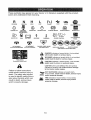
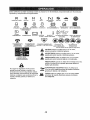
These symbols may appear on your tractor or in literature
Learn and understand their meaning°
R
N
H
L
REVERSE
NEUTRAL
HIGH
LOW
CHOKE
supplied
FAST
with the product.
SLOW
IGNITION SWITCH
ENGINE
OFF
REVERSE
ENGINE
ON
ENGINE
START
PARKING BRAKE
MOWER HEIGHT
MOWER
LIFT
OPERATION
SYSTEM (ROS)
LIGHTS ON
FUEL
BATTERY
REVERSE
FORWARD
CRUISE
CONTROL
CLUTCH/BRAKE
PEDAL
®@@@@
A]TACHMENT
CLUTCH
DISENGAGED
ATTACHMENT
CLUTCH
ENGAGED
DANGER_
KEEP
&
&
A
Failure to follow instructions
could result in serious injury or
death. The safety alert symbol
is used to identify safety information about hazards wHch can
result in death, serious injury
and/or property damage,
HANDS
AND FEET AWAY
KEEP AREA CLEAR
SLOPE HAZARDS
(SEE SAFETY RULES SECTION)
DANGER indicaies a hazard whicl_, if not avoided,
will result in death or serious injury°
WARNING indicates a hazard which, if not avoided,
could result in death or serious injury.
CAUTION indicates a hazard which, if not avoided,
might result in minor or moderate injury.
CAUTION when used without the alert symbol,
indicates a situation that could result in damage
to the tractor and/or engine.
HOT SURFACES indicates a hazard which,
if not avoided, could result in death, serious
and/or property damage.
FIRE indicates a hazard which, if not avoided,
could result tn death, serlous injury and/or
property damage.
13
injury
KNOW
YOUR
TRACTOR
READ THIS OWNER'S
TRACTOR
MANUAL
AND SAFETY
RULES
BEFORE
OPERATING
Compare the illustrations with your tractor to familiarize yourself with the locations
various controls and adjustments,
Save this manual for future reference,
(A) ATTACHMENT
LIFT LEVER - Used to
raise and lower the mower or other attachments mounted to your tractor.
(B) BRAKE PEDAL - Used for braking the
tractor and starting the engine.
(C) PARKING BRAKELocks clutch!brake
pedal into the brake position.
(D) THROTTLE CONTROLUsed to control engine speed.
(E) ATTACHMENT
CLUTCH
SWITCH
- Used to engage the mower blades, or other
attachments
mounted to your tractor.
(F) IGNITION SWITCH - Used for starting
and stopping the engine.
(G) REVERSE
OPERATION
SYSTEM
(ROS) "ON" POSITIONAllows operation
of mower or other powered attach ment while
in reverse_
YOUR
of
(H) LIGHT SWITCH - Turns the headlights
on and off°
(J) CRUISE CONTROL
LEVER - Used to set
forward movement of tractor at desired speed
without holding the forward drive pedal.
(K) FORWARD
DRIVE PEDAL - Used for
forward movement of tractor.
(L) REVERSE DRIVE PEDAL- Used for reverse
movement of tractor.
(N) CHOKE CONTROLUsed when starting
a cold engine.
(P) SERVICE REMINDER
/ HOUR METER
- indicates when service is required for the
engine and mower.
14
The operation of any tractor can result in foreign objects thrown into the
eyes, which can result in severe eye damage° Always wear safety glasses
or eye shields while operating your tractor or performing any adjustments
or repairs° We recommend standard safety glasses or a wide vision safety
mask worn over spectacles°
HOW
TO USE
YOUR
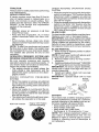
TO SET PARKING
TRACTOR
ENGINE
BRAKE
• Move throttle control (D) between half and
full speed (fast) position.
NOTE: Failure to move throttle control be-
Your tractor is equipped with an operator
presence sensing switch. When engine is
running, any attempt bythe operator to leave
the seat without first setting the parking brake
will shut off the engine.
1. Depress brake pedal(B) allthewaydown
and hold.
2.
tween half and full speed (fast) position, before stopping, may cause engine to "backfire".
• Turn ignition key (F) to "STOP" position
and remove key. Always remove keywhen
leaving tractor to prevent unauthorized use.
Pull parking brake lever (C) up and hold,
release pressure from brake pedal (B),
then release parking brake lever. Pedal
should remain in brake position.
Make
sure parking brake will hold tractor secu re.
• Never use choke (N) to stop engine.
IMPORTANT:
Leaving the ignition switch in
any position other than "STOP" will cause
the battery to discharge and go dead.
NOTE: Under certain conditionswhen
tractor
is standing idle with the engine running, hot
engine exhaust gases may cause "browning" of grass. To eliminate this possibility,
always stop engine when stopping tractor
on grass areas.
CAUTION:
Always stop tractor completely, as described above, before leaving
the operator's position.
STOPPING
MOWER
BLADES-
TO USE THROTTLE
- To stop mower blades, move attachment
clutch clutch lever to disengaged position
(1"_) Attachment
Clutch Switch
"Engaged"
GROUND
-
CONTROL
(D)
Always operate engine at full speed (fast).
• Operating engine at less than full speed
(fast) reduces engine's operating efficiency.
• Full speed (fast) offers the best mower
performance.
(r_'_)Attachment
Clutch Switch
"Disengaged"
TO USE CHOKE
CONTROL
(N)
Use choke control whenever you are starting
a cold engine. Do not use to start a warm
engine.
• To engage choke control, pull knob out.
Slowly push knob in to disengage.
DRIVE-
• "fb stop ground drive, depress brake pedal
all the way down.
IMPORTANT:
Forward and reverse drive
pedals return to neutral position when not
depressed.
15
TO MOVE
FORWARD
AND BACKWARD
The cutting height range is approximately
I" to 4". The heights are measured from the
ground to the blade tip with the engine not running. These heights are approximate and may
vary depending upon soil conditions, height
of grass and types of grass being mowed.
• The average lawn should be cut to approximately 2-1/2" during the cool season
and to over 3" during hot months.
For
healthier and better looking lawns, mow
often and after moderate growth.
• For best cutting performance,
grass over
6" in height should be mowed twice. Make
the first cut relatively high; the second to
desired height.
The direction and speed of movement
is
controlled by the forward and reverse drive
pedals.
I. Start
tractor
and release
parking
brake.
2 Slowly depress forward(K) or reverse(L)
drive pedal to begin movemenL Ground
speed increases the further down the
pedal is depressed,,
TO ADJUST
TO USE CRUISE
CONTROL
The cruise control feature can be used for
forward travel onlyo
SYSTEM CHARACTERISTICS
The cruise control should only be used
while mowing or transporting
on relatively
smooth, straight surfaces. Other conditions
such as trimming at slow speeds may cause
the cruise control to disengage. Do not use
the cruise control on slopes, rough terrian
or while trimmimg or turning.
• With forward drive pedal depressed
to
desired speed, pull cruise control lever
(J) up and hold while lifting your foot off
the pedal, then release the lever.
To disengage the cruise control, depress the
brake pedal, tap on forward drive pedal or
push the cruise control lever down.
TO ADJUST
MOWER
CUTTING
GAUGE
WHEELS
Gauge wheels are properly adjusted when
they are slightly off the ground when mower
is at the desired cutting height in operating
position. Gauge wheels then keep the deck
in proper position to help prevent scalping
in most terrain conditions.
NOTE: Adjust gauge wheels with tractor on
a flat level surface.
1. Adjust mower to desired cutting height
(See "TO ADJUST MOWER CUTTING
HEIGHT' in this section of manual).
2. With mower in desired height of cut position, gauge wheels should be assembled
so they are slightly off the ground. Install
gauge wheel in appropriate hole. Tighten
securely°
3_ Repeat for all, installing gauge wheel in
same adjustment hole.
HEIGHT
The position of the attachment lift lever (A)
determines the cutting height.
• Put attachment lift lever in desired cutting
height slot.
• Slide pointer tab (T) to desired cutting
height as a reminder for nexttime you mow.
TO OPERATE
MOWER
Your tractor is equipped with an operator
presence sensing switch. Any attempt by the
operator to leave the seat with the engine
running and the attachment clutch engaged
will shut off the engine. You must remain
fully and centrally positioned in the seat to
prevent the engine from hesitating or cutting
offwhen operating your equipment on rough,
rolling terrain or hills.
1. Select desired height of cut with attach_
merit lift lever.
2. Start mower blades by engaging attachment clutch control.
!6
TO STOP MOWER
Disengage
BLADES
attachment
TO OPERATE
clutch control.
_CAUTION:
Do not operate the mower
without either the entire grass catcher, on
mowers so equipped, or the deflector shield
(S) in place.
REVERSE
OPERATION
SYSTEM
ON HILLS
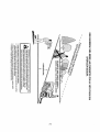
_WARNtNG:
DO not drive up or down
hills with slopes greater than 15 ° and do not
drive across any slope. Use the slope guide
provided at the back of this manual.
• Choose the slowestspeed
before starting
up or down hills+
• Avoid stopping
or changing speed on
hills.
• If stopping is absolutely necessary, push
brake pedal quickly to brake position and
engage parking brake.
• To restart movement, slowly release parking brake and brake pedal.
, Slowly depress appropriate drive pedal to
slowest setting.
° Make all turns slowly_
(ROS)
TO TRANSPORT
Your tractor is equipped with a Reverse
Operation System (ROS). Any attempt by
the operator to travel in the reverse direction
with the attachment clutch engaged will shut
off the engine unless ignition key is placed
in the ROS "ON" position.
When pushing or towing your tractor, be
sure to disengage transmission
by placing
freewheel control in freewheeling
position.
Free wheel control is located at the rear
drawbar of tractor+
• Raise attachment
lift to highest position
with attachment
lift control.
• Pull freewheel control out and into the slot
_WARNING:
Backing
up with the at+
tachment clutch engaged while mowing is
strongly discouraged.Purning
the ROS "O N",
to allow reverse operation with the attach+
ment clutch engaged, should only be done
when the operator decides it is necessary to
reposition the machine with the attachment
engaged. Do not mow in reverse unless
absolutely
necessary.
and release so it is held in the disengaged
position.
- Do not push or tow tractor at more than
two (2) MPH°
• To reengage transmission,
reverse above
procedure.
USING THE REVERSE OPERATION SYSTEM
Only use ifyou are certain no children or other
bystanders will enter the mowing area.
1. Depress brake pedal all the way down.
2. With engine running, turn ignition key
counterclockwise
to ROS "ON" position+
3. Look down and behind before and while
backing.
4. Slowly depress reverse drive pedal to
start movement.
5+ When use of the ROS is no longer
needed, turn the ignition key clockwise
to engine "ON" position.
ROS "ON +'Position
NOTE: To protect hood from damage when
transporting your tractor on a truck or atrailer,
be sure hood is closed and secured to tractor.
Use an appropriate
means of tying hood to
tractor (rope, cord, etc.).
TOWING
MENTS
Engine "ON" Position
(Normal Operating)
CARTS
AND
OTHER
ATTACH-
Tow only the attachments
that are recommended by and comply with specifications
of the manufacturer
of your tractor. Use
common sense when towing. Too heavy of
a load, while on a slope, is dangerous. Tires
can lose traction with the ground and cause
you to lose control of your tractor.
t7
SERVICE REMINDER/HOUR
METER
Service reminder shows the total number
of hours the engine has run and flashes to
indicate that the engine or mower needs servicing. When service is required, the service
reminder will flash for two hours. To service
engine and mower, see the Maintenance
section of this manual.
NOTE: Service
reminder runs when the
ignition key is in any position but "STOP".
For acurate reading, be sure key remains
in the "STOP" position when engine is not
running.
BEFORE
STARTING
THE ENGINE
CHECK
ENGINE
CAUTION:
Alcohol blended fuels (called
gasohot or using ethanol or methanol) can
attract moisture which leads to separation
and formation of acids during storage. Acidic
gas can damage the fuel system of an engine
while in storage. To avoid engine problems,
the fuel system should be emptied before
storage of 30 days or longer. Drain the gas
tank, start the engine and let it run until the
fuel lines and carburetor are empty° Use fresh
fuel next season° See Storage Instructions
for additional information.
Never use engine
or carburetor cleaner products in the fuel tank
or permanent damage may occur.
OIL LEVEL
The engine in your tractor has been shipped,
from the factory, already filled with summer
weight oil.
I. Check engine oil with tractor on level
groun&
2. Unthread and remove oil fill cap/dipstick;
wipe oil off. Reinsert the dipstick into the
tube and rest oil fill cap on the tube_ Do
not thread the cap onto the tube. Remove
and read oil level. If necessary, add oil
until "FULl/' mark on dipstick is reached°
Do not overfill.
3. For cold weather operation
you should
change oil for easier starting (See the oil
viscosity chart in the Maintenance section
of this manual),
4. To change engine oil, see the Maintenance
section in this manual.
5. Fill fuel tank to bottom of filler neck° Do
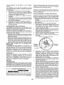
RESERVE FUEL VALVE OPERATION
I. Raise seat to access reserve fuel
valve.
2. tn normal operation, valve should be
set to primary (as shown in view)
3. If tractor runs out of fuel, rotate valve
handle to reserve°
4. Drive tractor to be refueled.
5. After refueling, return valve to primary
position.
Reserve
Fuel Vatve
@
not overfill. Use fresh, clean, regular
unleaded gasoline with a minimum of
87 octane. (Use of leaded gasoline will
increase carbon and lead oxide deposits
and reduce valve life). Do not mix oil
with gasoline.
Purchase fuel in quantities that can be used within 30 days to
u_elaSsure fuel freshness.
CAUTION;
Wipe off any spilled oil or
. Do not store, spill or use gasoline
near an open flame.
IMPORTANT:
When operating in temperatures below 32°F(0°C), use fresh, clean
winter grade gasoline to help ensure good
cold weather starting,
Primary
TO START
ENGINE
When starting the engine for the first time or
if the engine has run out of fuel, it will take
extra cranking time to move fuel from the
tank to the engine.
1. Be sure freewheel control is in the transmission engaged position.
2. Sit on seat in operating position, depress
brake pedal and set parking braker
3. Move attachment clutch to disengaged
position.
4o Move throttle control to fast position
5. Pull choke control out for a cold engine
start attempt. For a warm engine start
attempt the choke control may not be
needed.
NOTE: Before starting, read the warm and
cold starting procedures below.
18
PURGE
6o Insert key into ignition and turn key
clockwise to start position and release
key as soon as engine starts. Do not run
starter continuously for more than fifteen
seconds per minute, if the engine does
not start after several attempts,
push
choke control in, wait a few minutes and
try again, tf engine still does not start, pull
the choke control out and retry,
_CAUTION:
Never engage or disengage
freewheel lever while the engine is running,
To ensure proper operation and performance,
it is recommended
that the transmission
be
purged before operating tractor for the first
time° This procedure will remove any trapped
air inside the transmission
which may have
developed during shipping of your tractor.
WARM WEATHER STARTING (50°F/10°C
and above)
7. When engine starts, slowly push choke
control in until the engine begins to run
smoothly.
If the engine starts to run
roughly, pull the choke control out slightly
for a few seconds and then continue to
push the control in slowly.
8.The attachments
and ground drive can
now be used. Ifthe engine does not accept
the load, restart the engine and allow it to
warm up for one minute using the choke
as described above.
IMPORTANT:
Should your transmission
require removal for service or replacement,
it should be purged after reinstallation before
operating the tractor.
1. Place tractor safely on a level surface that is clear of objects and open - with
engine off and parking brake set.
2. Disengage
transmission
by placing
freewheel control in disengaged position
(See "TO TRANSPORT"
in this section
of manual),
3. Sitting in the tractor seat, start engine.
After the engine is running, move throttle
controlto slow position. Disengage parking brake.
COLD WEATHER
STARTING
(50°1=/10°C
and below)
9. When engine starts, slowly push choke
control in until the engine begins to run
smoothly. Continue to push the choke
control in small steps allowing the engine
to accept small changes in speed and
load, until the choke control is fully in.
If the engine starts to run roughly, pull
the choke control out slightly for a few
seconds and then continue to push the
control in slowly. This may require an
engine warm-up
period from several
seconds to several minutes, depending
on the temperature.
AUTOMATIC
TRANSMISSION
WARM
_I_CAUTION:
At any time, during step 4,
there may be movement of the drive wheels.
4.
5,
6.
UP
Before driving the unit in cold weather, the
transmission should bewarmed up as follows:
1.
TRANSMISSION
7,
Be sure the tractor is on level ground,
2,
Release the parking brake and let the
brake slowly return to operating position.
3. Allow one minute for transmission
to
warm up. This can be done during the
engine warm up period.
4, The attachments
can be used during the
engine warm-up period after the transmission has been warmed up and may require
the choke control be pulled out slightly.
NOTE: If at a high altitude (above 3000 feet)
or in cold temperatures
(below 32°F/0°C)
the carburetor fuel mixture may need to be
adjusted for best engine performance
(see
'q'O ADJUST CARBURETO R" in the Service
and Adjustments
section of this manual),
8o
Depress forward drive pedal to full forward
position and hold for five (5) seconds and
release pedal. Depress reverse drive
pedal to full reverse position and hold
for five (5) seconds and release pedal,
Repeat this procedure three (3) times,
Shutoff engine and set parking brake.
Engage transmission
by placing freewheel control in engaged position (See
"TO TRANSPORT"
in this section of
manual),
Sitting in the tractor seat, start engine.
After the engine is running, move throttle
control to half (1/2) speed, Disengage
parking brake.
Drive tractor forward for approximately
five feet then backwards
for five feet°
Repeat this driving
procedure
three
times,
Your transmission
is now purged
ready for normal operation.
19
and now
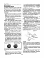
MOWING TiPS
* Tire chains cannot be used when
the
mower housing is attached to tractor.
Mower should be properly leveled for best
mowing performance.
See "TO LEVEL
MOWER HOUSING"
in the Service and
Adjustments
section of this manual.
The left hand side of mower should be
used for trimming.
Drive so that clippings are discharged onto
the area that has already been cut. Have
the cut area to the right of the tractor. This
will result in a more even distribution of
clippings and more uniform cutting.
When mowing targe areas, start by turning
to the right so that clippings will discharge
away from shrubs, fences, driveways,
etc. After one or two rounds, mow in the
opposite direction making left hand turns
until finished.
f
"-
• if grass is extremely
tall, it should be
mowed twice to reduce load and possible
fire hazard from dried clippings.
Make
first cut relatively high; the second to the
desired height.
• Do not mow grass when it is weL Wet
grass will plug mower and leave undesirable clumps.
Allow grass to dry before
mowing.
° Always
operate engine at full throttle
when mowing
to assure better mowing performance
and proper discharge
of material,
Regulate ground speed by
selecting a low enough speed to give the
mower cutting performance as well as the
quality of cut desired.
• When operating
attachments,
select a
ground speed that will suit the terrain and
give best performance
of the attachment
being used,
20
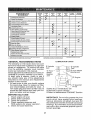
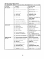
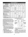
MAINTENANCE
SCHEDULE
B_FORE
EACH
USE
EVERY
EVERY
EVERY
EVERY
S
25
BO
I01]
HOURS
HOURS
HOURS
HOURS
=,,,"
Check Brake Operation
EVERY
BEFORE
SEASON
STORAGE
v
Check T!re Pressure
T
CheckOpFra_or,Presence
& Ros sy_!em_
V" ........
A
Check for Loose Fasleners
_"
C
T
ChecldRepbce
Mower
Lubrication Chart
O
Check
Blades
v'=
v"
,
v"
R 'CleanB'ai'tery
andTerminal,
,,
Clean
v'
Battery Level
l
Debris ofi Steering
Check Transaxle
Check
Mower
v"
Oil Level
Engine
V'
v'
r
Check V-Bells
Change
.
'
Cooling
Levelness
Check Enqine
i
!
Piate
v"
v"
Oil (with oil filter)
,
v',,,
J
Ctean
Filler Oil (without oil _tlter)
.Chang eAir
5ngtne
G
I
CleanAtr
Screen
V'
!,nspect MutfledSparkArrester
Reprace
Q!!FiI!er (!f equipped)
Ni
E! c,eanEnginecoo,.o Fi.s
I_,2
i
.............
_T
,Fle,p,!aceSpark Piu9 ...........
,R,epla.ce Air Fit!or Paper Carlridge
'
....
..............................
_
'
I_=
i!
_
....... Re£,lac, e Fuel Filler
t. ChangO mere Often w._en epemt_rl
GENERAL
!_
_{_er # t_¢A_y_a# #t _ _4_h ambeR{ te_e_t_tu=e=
1.
2.
3.
4.
5.
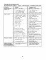
LUBRICATION CHART
RECOMMENDATIONS
The warranty on this tractor does not cover
items that have been subjected to operator
abuse or negligence.
To receive full value
from the warranty, operator must maintain
tractor as instructed in this manual.
Some adjustments will need to be made periodically to properly maintain your tractor,
At least once a season, check to see if
you should make any of the adjustments
described in the Service and Adjustments
section of this manual,
• At least once a year you should replace
the spark plug, clean or replace air filter,
and check blades and belts for wear. A
new spark plug and clean air filter assure
proper air-fuel mixture and help your engine run better and last longer.
BEFORE
EACH
'
(_ Spindle
Zerk
_ Spindle
Zerk
Front
Wheel
Bearing
_@ Front Wheel
Bearing zerk
zerk
_(_')Engine
=
',
',
(0SAE
i
,
Gearshift
_ Pivots
30 or 10w30 Motor Oil
_) General Purpose Grease
L,_Refer to Maintenance "ENGINE"
Section
USE
Check engine oil level.
Check brake operation.
Check tire pressure.
Check operator presence and
ROS systems for proper operation.
Check for loose fasteners.
IMPORTANT;
Do not oil or grease the pivot
points which have special nylon bearings°
Viscous lubricants will attract dust and dirt
that will shorten the fife of the seIFlubricating
bearings. If you feel they must be lubricated,
use only a dry, powdered graphite type lubricant sparingly.
21
TRACTOR
CHECK
REVERSE
SYSTEM
Always observe safety rules when performing
any maintenance_
BRAKE OPERATION
• Maintain proper air pressure in all tires
(See PSi on tires).
• Keep tires free of gasoline, oil, or insect
control chemicals
which can harm rubber.
° Avoid stumps, stones, deep ruts, sharp
objects and other hazards that may cause
tire damage.
NOTE: To seal tire punctures and prevent
flat tires due to slow leaks, tire sealant may
be purchased from your local parts dealer.
Tire sealant also prevents tire dry rot and
corrosion.
OPERATOR
PRESENCE
SYSTEM AND
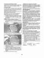
For best results mower blades must be sharp.
eplace worn, bent or damaged blades°
CAUTION:
Use only a replacement blade
approved by the manufacturer of your tractor.
Using a blade not approved by the manufacturer of your tractor is hazardous, could
damage your tractor and void your warranty.
BLADE
NOTE: Protect your hands with gloves and/
or wrap blade with heavy cloth.
2_ Remove blade bolt by turning counterclockwise.
3. tnstallnew bladewith stamped"THIS SIDE
UP" facing deck and mandrel assembly.
IMPORTANT:
To ensure proper assembly,
center hole in blade must align with star on
mandrel assembly°
4. Install and tighten blade bolt securely
(45-55 Ft. Lbs. torque).
IMPORTANT:
Special blade bolt is heat
treated.
Mandrel
PRESENCE
- When the engine is running,
by the operator to leave the
first setting the parking brake
off the engine.
° When the engine is running
tachment clutch is engaged,
by the operator to leave the
shut off the engine.
• The attachment clutch should
ate unless the operator is in
ROS "ON" Position
REMOVAL
1_ Raise mowerto highest position to allow
access to blades.
REVERSE OPERATION
SYSTEM (ROS)
Be sure operator
presence
and reverse
operation systems are working properly.
If
your tractor does not function as described,
repair the problem immediately.
° The engine should not start unless the
brake pedal is fully depressed,
and the
attachment clutch control is in the disengaged position°
OPERATOR
(ROS)
• When the engine is running with the ignition
switch in the engine "ON" position and the
attachment clutch engaged, any attempt
by the operator to shift into reverse should
shut off the engine.
• Whenthe engine is runningwith the ignition
switch in the ROS "ON" position and the
attachment clutch engaged, any attempt
by the operator to shift into reverse should
NOT shut off the engine°
BLADE CARE
If tractor requires more than five (5) feet to
stop at highest speed in highest gear on a
level, dry concrete or paved surface, then
brake must be serviced. (See "TO CHECK
BRAKE" in the Service and Adjustments
section of this manual)_
TIRES
CHECK
SYSTEM
OPERATION
Assembly
any attempt
seat without
should shut
Blade
and the atany attempt
seat should
' Star
BATTERY
never operthe seat.
Center Hole
Your tractor has a batter,/charging
system
which is sufficient for normal user However,
periodic charging of the battery with an automotive charger will extend its life.
• Keep battery and terminals clean.
• Keep battery bolts tight.
° Keep small vent holes open.
• Recharge at 6-10 amperes for 1 hour.
NOTE: The original equipment
battery on
your tractor is maintenance
free. Do not
attempt to open or remove caps or covers.
Adding or checking level of electrolyte
is
not necessary.
Engine "ON" Position
(Normal Operating)
22
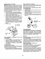
TO CLEANBATTERYAND TERMINALS
Corrosionanddirt on the batteryandterminalscan causethe batteryto "leak"power.
1. Removeterminalguard,,
2. DisconnectBLACK battery cable first
then RED battery cable and remove
batteryfromtractor_
3. Rinsethebatterywithplainwateranddry.
4. Cleanterminalsandbatterycableends
with wire brushuntilbright,
5. Coatterminalswithgreaseor petroleum
jelly.
6. Reinstall battery (See "REPLACING
BATTERY"in the SERVICEAND ADJUSTMENTSsectionof this manual).
TRANSAXLEMAINTENANCE
The transmission fan and cooling fins should
be kept clean to assure proper cooling_ Do
not attempt to clean fan or transmission while
engine is running or while the transmission
is hoL To prevent possible damage to seals,
do not use high pressure water or steam to
clean transaxle.
• Inspect cooling fan to be sure fan blades
are intact and clean.
• lnspectcoolingfinsfordirt,
grass clippings
and other materials. To prevent damage to
seals, do not use compressed air or high
pressure sprayer to clean cooling fins.
TRANSAXLE
PUMP FLUID
Closed
_
and
Locked
_--_
J _
_
-7_
.... ..N
_.]L -_'"
_
|
Drain
_Tube
Yellow Cap
4. To open, pull out on the drain valve.
5. After oil has drained completely, close and
lock the drain valve by pushing inward
and turning clockwise until the pin is in
the locked position as shown.
6. Remove the drain tube and replace the
cap onto the end of the drain valve.
7_ RefiU engine with oil through oil fill dipstick
tube. Pour slowly. Do not overfill. For
approximate
capacity see "PRODUCT
SPECIFICATIONS"section
of this manual.
8. Use gauge on oil fill cap/dipstick
for
checking level,
insert dipstick into the
tube and rest the oil fill cap on the tube_
Do not thread the cap onto the tube when
taking reading. Keep oil at "FIJLI_ line
on dipstick. Tighten cap onto the tube
securely when finished.
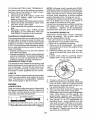
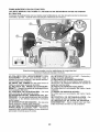
LUBRICATION
Only use high quality detergent oil rated with
API service classification SG-SL. Select the
oil's SAE viscosity grade according to your
expected operating temperature.
GRADES
!]EFO_E
OIL
Determine
temperature
range expected
before oil change.
All oil must meet API
service classification
SG-SL.
• Be sure tractor is on level surface_
Position--'_..
ENGINE
At,mc1PAIrED
ENGINE
Oil Drain Valve
V-BELTS
Check V-belts for deterioration and wear after
100 hours of operation and replace if necessary_ The belts are not adjustable. Replace
belts if they begin to slip from wear.
.... TF-_/iPERATURE RAHG5
TO CHANGE
• Oil will drain more freely when warm,
. Catch oil in a suitable container.
1. Remove oil fill cap/dipstick.
Be careful
not to allow dirt to enter the engine when
changing oil.
2. Remove yellow cap from end of drain
valve and install the drain tube onto the
fitting.
3. Unlock drain valve by pushing inward
slightly and turning counterclockwise.
The transaxle was sealed at the factory and
fluid maintenance
is not required for the life
of the transaxle_ Should the transaxle ever
leak or require servicing, contact your nearest Sears or other qualified service center_
SAE VISCOSITY
NOTE" Although multi-viscosity
oils (5W30,
10W30 etc,) improve starting in cold weather,
they will result in increased oil consumption
when used above 32°E Check your engine
oil level more frequently to avoid possible
engine damage from running low on oil,
Change the oil after every 50 hours of o peration or at least once a year if the tractor is
not used for 50 hours in one year.
Check the crankcase oil level before starting
the engine and after each eight (8) hours
of operation.
Tighten oil fill cap/dipstick
securely each time you check the oil level
NEX"Ir D'i'L'CHANGE
23
AIR FILTER
CLEAN
Your engine will not run properly using a
dirty air filter. Service paper cartridge every
two months or every 25 hours of operation,
whichever occurs first.
Air screen must be kept free of dirt and chaff
to prevent engine damage from overheating.
Clean with a wire brush or compressed air to
remove dirt and stubborn dried gum fibers.
Service paper cartridge more often under
dusty conditions.
Replace the paper cartridge annually, or after
every 100 hours of operation,
TO SERVICE
CLEAN
AIR SCREEN
AIR INTAKE/COOLING
AREAS
To ensure proper cooling, make sure the
grass screen, cooling fins, and other external surfaces of the engine are kept clean
at all times°
CARTRIDGE
Every !00 hours of operation (more often
under extremely
dusty, dirty conditions),
remove the blower housing and other cooling
shrouds. Clean the cooling fins and external
surfaces as necessary. Make surethe cooling
shrouds are reinstalled.
• Replace a dirty, bent, or damaged cartridge. Handle new cartridge carefully; do
not use if the rubber seal is damaged.
NOTE:
Do not wash the paper cartridge
or use pressurized air, as this will damage
the cartridge°
!o Open door (A) on the blower housing to
access the air cleaner element (B)o
NOTE:
Operating the engine with ablocked
grass screen, dirty or plugged cooling fins,
and/or cooling shrouds removed will cause
engine damage due to overheating_
MUFFLER
Inspect and replace corroded muffler and
spark arrester (if equipped) as it could create
a fire hazard and/or damage.
SPARK
2,
Unhook the latch
element.
(C) and remove
PLUG(S)
Replace spark plug(s) at the beginning of
each mowing season or after every I00
hours of operation, whichever occurs first.
Spark plug type and gap setting are shown
in "PRODUCT
SPECIFICATIONS"
section
of this manual.
the
IN-LINE
FUEL FILTER
The fuel filter should be replaced once each
season.
If fuel filter becomes clogged, obstructing fuel flow to carburetor, replacement
is required.
1. With engine cool, remove filter and plug
fuel line sections.
2. Place new fuel filter in position in fuel line
with arrow pointing towards carburetor.
3_ Be sure there are no fuel line leaks and
clamps are properly positioned.
4. Immediately wipe up any spilled gasoline.
3.
Gently tap the paper element to dislodge
dirt.
Clam__arnp
4.
Clean all air cleaner components
of any
accumulated
dirt or foreign material°
Prevent any dirt from entering the throat
of carburetor.
5. Install cleaned or new element on the
base and secure with latch.
6. Close and latch the door.
Fuel Filter
24
CLEANING
°
°
Clean engine, battery, seat, finish, etc.
of all foreign matter.
Clean debris from steering plate.
Debris can restrict clutch/brake
pedal
shaft movement, causing belt slip and
loss of driver
A CAUTION:
Avoid
movable parts
all pinch
points
and
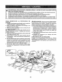
4.
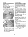
Pull back the lock collar of the nozzle
adapter and push the adapter onto the
deck washout port at the left end of the
mower deck. Release the lock collar to
lock the adapter on the nozzle,
IMPORTANT:
Tug hose ensuring connection is secure,
Keep finished surfaces and wheels
free of all gasoline, oil, etc.
.
Protect painted surfaces with automotive type wax.
We do not recommend using a garden hose
or pressure washer to clean your tractor
unless the engine and transmission
are
covered to keep water out. Water in engine
or transmission will shorten the useful life of
your tractor. Use compressed
air or a leaf
blower to remove grass, leaves and trash
from tractor and mower,
5o
Turn the water on.
6,
While sitting in the operator's position
on the tractor, re-start the engine and
place the throttle lever in the Fast ",#_"
position_
•
IMPORTANT:
Recheck
certain the area is clear,
1.
Drive the tractor to a level, clear spot
on your lawn, near enough to a water
spigot for your garden hose to reach.
IMPORTANT:
Make certain the tractor's
discharge chute is directed AWAY from your
house, garage, parked cars, etc. Remove
bagger chute or mulch cover if attached_
2.
Makesurethe
attachment clutch control
is. in the "DISENGAGED"
position, set
the parking brake, and stop the engine.
3.
area
making
7,
Move the tractor's attachment
clutch
control to the "ENGAGED"
position°
Remain
in the operator's
position
with the cutting deck engaged until the
deck is cleaned.
8,
Move the tractor's attachment
clutch
control to the "DISENGAGED"
position, Turn the ignition key to the STOP
position to turn the tractor's engine off,
_Jrn the water off.
9.
Pull back the lock collar of the nozzle
adapter to disconnect the adapter from
the nozzle washout port,
10.
Move the tractor to a dry area, preferably a concrete or paved area° Place
the attachment
clutch control in the
"ENGAGED" position to remove excess
water and to help dry before putting the
tractor away,
DECK WASHOUTPORT
Your tractor's
deck is equipped
with a
washout port on its surface as part of its
deck wash system, it should be utilized after each use.
the
_WARNING:
A broken or missing washout
fitting could expose you or others to thrown
objects from contact with the blade.
, Replace broken or missing washout fitting
immediately, prior to using mower again.
• Plug any holes in mower with bolts and
Iocknuts.
Thread the nozzle adapter (packaged
with your tractor's Operator's Manual)
onto the end of your garden hose°
25
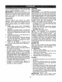
WARNING; TO AVOID SERIOUS INJURY, BEFORE PERFORMING ANY SERVICE OR
ADJUSTMENTS:
Depress clutch/brake
pedal fully and set parking brake,
3. Place attachment clutch in "DISENGAGED"
position.
4. Turn ignition key to "STOP" and remove key,
5. Make sure the blades and all moving parts have completely stopped.
6. Disconnect spark plug wire from spark plug and place wire where it cannot
in contact with plug.
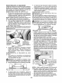
TO REMOVE MOWER
1. Place attachment clutch in "DISEN2,
3.
CAUTION:
6.
7.
After rear lift links are discon-
nected, the attachment lift lever will be spring
loaded, Have a tight grip on lift lever when
changing position of the lever.
GAGED" position,
Lower attachment
lift lever to its lowest
position,
Disengage belt tension rod (K) from lock
bracket (L),
8.
From right side of mower, disconnect
anti-sway bar (S) from right rear mower
bracket (D) - remove retainer spring and
washer and pull mower toward you until
the bar falls from the hole in bracket.
9. Turn tractor steering wheel to the left as
far as it will go,
10. Slide mower out from under right side of
tractor,
_,_ CAUTION:
Belt tension rod is spring
loaded, Have a tight grip on rod and release
slowly,
4. Remove mower belt from electric clutch
5.
come
pulley (M),
Disconnect front link (E) from mower remove retainer spring and washer,
Go to either side of mower and disconnect
mower suspension
arm (A) from chassis and rear lift link (C) from rear mower
bracket (D) - remove retainer springs and
washers,
Go to other side of mower and disconnect
the suspension
arm and rear lift link.
TO INSTALL
MOWER
Follow procedure
described
in "INSTALL
MOWER AND DRIVE BELT" in the Assembly
section of this manual.
26
TO LEVEL MOWER
Make sure tires are properly inflated to the
PS! shown on tires_ If tires are over or under
inflated, it may affect the appearance of your
lawn and lead you to think the mower is not
adjusted properly,
VISUAL
StDE-TO.-SIDE
4,
If adjustment
is necessary, see steps 2
and 3 in Visual Adjustment
instructions
above,
5. Recheck measurements,
adjust if necessary until both sides are equal.
FRONT_TO-BACK
ADJUSTMENT
IMPORTANT:
Deck must be level sideto-side,
ADJUSTMENT
1. With all tires properly inflated and if your
lawn appears unevenly cut, determine
which side of mower is cutting lower.
NOTE: As desired, you can raise the low
side of mower or lower the high side.
2. Go to side of mower you wish to adjust.
3. With a 3/4" or adjustable
wrench, turn
lift link adjustment
nut (A) to the left to
lower the mower, or, to the right to raise
the mower.
To obtain the best cutting results, the mower
blades should be adjusted so the front tip is
1/8" to 1/2" lower than the rear tip when the
,_ower is in its highest position°
CAUTION:
Blades are sharp_ Protect
your hands with gloves and/or wrap blade
with heavy cloth,
• Raise mower to highest position,
, Position any blade so the tip is pointing
straightforward.
Measure distance (B) to
the ground at front and rear tip ofthe blade.
, If front tip of blade is not 1/8" to 1/2" lower
than the rear tip, go to the front of tractor.
• With an 11/I6"
or adjustable
wrench,
loosen jam nut A several turns to clear
adjustment
nut B,
• With a 3/4" or adjustable
wrench, turn
front link adjustment
nut (B) clockwise
(ltighten) to raise the front of mower, or;
counterclockwise
(loosen) to lower the
front mower.
(
Turn nut rig
to raise mower
Turn nut left
to lower mower
NOTE: Each full turn of adjustment nut will
change mower height about 3/16'L
4_ Test your adjustment
by mowing some
uncut grass and visually checking the
appearance. Readjust, if necessary, until
you are satisfied with the results.
PRECISION
SIDE-TO-SIDE
ADJUSTMENT
1, With all tires properly inflated, park tractor
on level ground or driveway.
,_ CAUTION:
Blades are sharp. Protect
your hands with gloves and/or wrap blade
with heavy cloth.
2. Raise mower to its highest position,
3, At both sides of mower, position blade at
side and measure the distance (A) from
bottom edge of blade to the ground° The
distance shou Id be the same on both sides _
27
Tighten adjust nut
B to raise mower
Loosen adjust
nut B to lower
mower
Loosen jam nut A first
NOTE; Each full turn of the adjustment nut
will change mower height about 1/8".
• Recheck measurements,
adjust if necessary until front tip of blade is 1/8" to 1/2"
lower than the rear tip.
• Hold adjustment nut in position with wrench
and tighten jam nut securely against adjustment nut.
TO REPLACE
MOWER
MOWER
DRIVE BELT
NOTE:
position of all belt guides and keepers.
2. Disconnect clutch wire harness (A).
3. Remove anti-rotation link (B) on rightside
of tractor.
4. Remove beltfrom stationary idler (C) and
clutching idler (D).
5. Pull belt slack toward rear of tractor.
Carefully
remove
belt upwards
from
transmission
input pulley and over cooling fan blades (F).
6. Remove
belt downward
from engine
pulley and around electric clutch (G).
7. Slide belt toward rear of tractor, off the
steering plate (H) and remove from tractor_
DRIVE BELT REMOVAL
1.
Park tractor on a level surface° Engage
parking brake.
2o Lower attachment lift lever to its lowest
3.
ed.
4.
5,
6.
Observe entire motion drive belt and
position°
Disengage belt tension rod (K) from lock
bracket (L).
AUTION= Belttension rod is spring loadHave a firm grip on rod and release slowly.
Remove screws (P) from R.H. and L.H_
mandrel covers and remove covers (Q)o
Remove any dirt orgrass clippings which
may have accumulated around mandrels
and entire upper deck surface°
Remove belt from electric clutch pulley
(M), both mandrel pulleys (R) and all idler
pulleys (S),
%
MOWER
DRIVE BELT INSTALLATION
I.
install belt around both mandrel pulleys
(R) and around idler pulleys (S) as shown°
2. Install belt onto electric clutch pulley (M)o
IMPORTANT:
Check belt for proper routing
in all mower pulley grooves.
3. Reassemble R.H. and L.H. mandrel covers (Q). Securely tighten all screws.
4o Engage belt tension rod (K) on locking
bracket (L).
A CAUTION: Belt tension rod is spring Ioadedo Have atight grip on rod and engage slowly.
5. Raise attachment
lift lever to highest
position,
TO REPLACE
MOTION
DRIVE
BELT INSTALLATION
4.
BELT
5.
Park the tractor on level surface.
Engage
parking brake.
For assistance,
there is a
belt installation guide decal on bottom side
of left footrest.
6.
7.
BELT REMOVAL!.
-
1. Install new belt from tractor rear to front,
over the steering plate (H) and above
clutch brake pedal shaft (J),
2. Pull belt toward front of tractor and roll belt
around electric clutch and onto engine
pulley (G).
3. Pull belt toward rear of tractor. Carefully
work belt down around transmission
8.
Remove mower
(See "TO REMOVE
MOWER" in this section of manual).
28
cooling fan and onto the input pulley (F).
Be sure belt is inside the belt keeper.
Install belt through stationary
idler (C)
and clutching idler (D).
Reinstall anti-rotation
link (B) on right
side of tractor° Tighten securely.
Reconnect clutch harness (A).
Make sure belt is in all pulley grooves
and inside all belt guides and keepers.
Install mower (See "TO INSTALL MOWER" in this section of manual).
TO CHECK
BRAKE
If tractor requires more than five (5) feet to
stop at highest speed in highest gear on a
level, dry concrete or paved surface, then
brake must be serviced.
You may also check brake by:
!o Park tractor on a level, dry concrete or
paved surface, depress brake pedal all
the way down and engage parking brake.
2. Disengage
transmission
by placing
freewheel
control in "transmission
disengaged" position. Pull freewheel control
out and into the slot and release so it is
held in the disengaged position.
The rear wheels must lock and skid when
you try to manually push the tractor forward°
if the rear wheels rotate, then the brake
needs to be serviced, Contact a Sears or
other qualified
service center.
BAT-
to the NEGATIVE (-) terminal (C) of fully
charged battery.
Connect the other end of the BLACK
cable (D) to good chassis ground,
from fuel tank and battery,
FOR REPAIRS
away
TO REMOVE
CABLES,
REVERSE
ORDER
1, BLACK cable first from chassis and then
from the fully charged battery.
2, RED cable last from both batteries.
Block up axle securety_
Remove axle cover, retaining ring and
washers to allow wheel removal (rear
wheels have a square key - Do not lose).
3. Repair tire and reassemble.
NOTE: On rear wheels only: align grooves in
rearwheel hub and axle, Insert square key.
4. Replace washers and snap retaining ring
securely in axle groove.
5. Replace axle cover.
NOTE: To seal tire punctures and prevent
flat tires due to slow leaks, purchase and
use tire sealant from Sears, Tire sealant also
prevents tire dry rot and corrosion.
Weak or Dead
Battery
Washers
Retaining
Ring "-kX
!
_Square
A WEAK
,_WARNING:
Lead-acid batteries gener_
ate explosive gases.
Keep sparks, flame
and smoking materials away from batteries.
Always wear eye protection when around
batteries
If your battery is too weak to startthe engine, it
should be recharged. (See "BATTERY" in the
MAINTENANCE
section of this manual).
If "jumper cables" are used for emergency
starting, follow this procedure:
IMPORTANT:
Your tractor is equipped with
a 12 volt system. The other vehicle must also
be a t 2 volt system° Do not use your tractor
battery to start other vehicles°
3.
i,
2.
Axle Cover
WITH
PC S ITIVE (+) terminal of each battery'(AB), taking care not to short against tractor
chassis.
2, Connect one end of the BLACK cable
ber is set at the factory and is normal. The
front wheel toeqn and cam ber are not adjustable. if damage has occurred to affect the
factory set front wheeltoe-in
or camber, contact a Sears or other qualified service center.
WHEEL
ENGINE
TO ATTACH JUMPER CABLES
1. Connect one end ofthe RED cable to the
FRONT WHEEL TOE-IN/CAMBER
"Your new tractor front wheel toe-in and cam-
TO REMOVE
TO START
TERY
Key (Rear
Wheel Only)
29
Fully Charged
Battery
REPLACING
BATTERY
_,WA R NING: Do not short battery terminals
by allowing a wrench or any other object to
contact both terminals at the same time.
Before connecting
battery, remove metal
bracelets,
wristwatch
bands, rings, etc.
Positive terminal must be connected first to
prevent sparking from accidental grounding.
1. Lift hood to raised position.
2. Disconnect BLACK battery cable (A) then
RED battery cable and carefully remove
battery from tractor.
3,
Install new battery with terminals in same
position as old battery.
4_ First connect RED battery cable (B) to
positive (+) batter,,, terminal with hex bolt
and keps nut as shown. Tighten securely.
Slide terminal cover (C) over terminal.
5_
Connect BLACK grounding cable to negative (-) battery terminal with remaining
hex bolt and keps nut. Tighten securely.
Close hood.
,
TO REMOVE HOOD AND GRILL
ASSEMBLY
1. Raise hood.
2'. Unsnap headlight wire connector.
3, Stand in front of tractor. Grasp hood at
sides, tilt toward engine and lift off of
tractor°
4. Whenreplacing
hood, be sureto reconnect
the headlight wire connector.
Hood
Headlight Wire
Connector
_, _ Negative
(Black)
Cable
TRANSMISSION
MENT
REMOVAL!REPLACE-
Should your transmission
require removal
for service or replacement,
it should be
purged after reinstallation
and before operating the tractor. See "PURGE TRANSMISSION" in the Operation section of this
manual.
ENGINE
Positive
(Red)
Cable
TO ADJUST
CABLE
TO REPLACE
The throttle control has been preset at
the factory and adjustment
should not be
necessary Check adjustment as described
below before loosening cable, If adjustment
is necessary, see engine manual.
TO ADJUST CHOKE CONTROL
HEADLIGHT
1o Raise hood.
2. Remove bulb holderfrom
BULB
the hole in the
backside of the grill.
3. Replace bulb in holder and install bulb
holder securely back into the hole in the
backside of the grill.
4. Close hood.
INTERLOCKS
AND RELAYS
THROTTLE
CONTROL
The choke control
has been preset at
the factory and adjustment
should not be
necessary, If adjustment
is necessary, see
engine manual.
TO ADJUST CARBURETOR
Your carburetor has been preset at the factory
and adjustment
should not be necessary.
However, minor adjustment may be required
to compensate
for differences
in fuel, temperature, altitude or load. If the engine does
need adjustment, see engine manual,
Loose or damaged wiring may cause your
tractor to run poorly, stop running, or prevent
it from starting.
, Check wiring.
TO REPLACE
FUSE
Replace with 30 amp automotive-type
plugin fuse. The fuse holder is located behind
the dash°
3O
ENGINE
Immediately pre pare your tracto r for sto rage
at the end of the season or if the tractor will
FUEL SYSTEM
,_t be used for 30 days or more.
WARNING:
Never store the tractor with
gasoline in the tank inside a building where
fumes may reach an open flame or spark,
Allow the engine to cool before storing in
any enclosure.
TRACTOR
Remove
mower from tractor for winter
storage, When mower is to be stored for a
period of time, clean it thoroughly, remove
all dirt, grease, leaves, etc, Store in a clean,
dry area.
1_ Clean entire tractor (See "CLEANING"
in the Maintenance
section
of this
manual),
2, Inspect and replace belts, if necessary
(See belt replacement instructions in the
Service and Adjustments
section of this
manual),
3, Lubricate as shown in the Maintenance
section of this manual.
4. Be sure that all nuts, bolts and screws
are securely fastened,
Inspect moving
parts for damage, breakage and wear.
Replace if necessary,
5. Touch up all rusted or chipped paint
surfaces; sand lightly before painting_
BATTERY
- Fully charge the batter/for
storage,
° After a period of time in storage, battery
may require recharging.
- To help prevent corrosion
and power
leakage during tong periods of storage,
battery cables should be disconnected
and battery cleaned thoroughly (see "TO
CLEAN BATTERY AND TERMINALS"
in
the Maintenance
section of this manual),
• After cleaning, leave cables disconnected
and place cables where they cannot come
in contact with battery terminals.
° If battery is removed
from tractor for
storage, do not store battery directly on
concrete or damp surfaces°
IMPORTANT:
It is important to prevent
gum deposits from forming in essential fuel
system parts such as carburetor, fuel hose,
or tank during storage. Also, alcohol blended
fuels (called gasohol or using ethanol or
methanol) can attract moisture which leads
to separation and formation of acids during
storage_ Acidic gas can damage the fuel
system of an engine while in storage,
• Empty the fuel tank by starting the engine
and letting it run until the fuel lines and
carburetor are empty.
• Never use engine or carburetor cleaner
products in the fuel tank or permanent
damage may occur_
° Use fresh fuel next season,
NOTE:
Fuel stabilizer is an acceptable
alternative
in minimizing
the formation
of
fuel gum deposits during storage°
Add
stabilizer to gasoline in fuel tank or storage
container. Always follow the mix ratio found
on stabilizer container.
Run engine at least
10 minutes after adding stabilizer to allow
the stabilizer to reach the carburetor, Do not
empty the gas tank and carburetor if using
fuel stabilizer,
ENGINE OIL
Drain oil (with engine warm) and replace
with clean engine oil. (See "ENGINE" in the
Maintenance
section of this manual).
CYLINDER(S)
1. Remove spark plug(s),
2. Pour one ounce of oil through spark plug
hole(s) into cylinder(s) o
3. Turn ignition key to start position for a
few seconds to distribute oilo
4,
Replace
with new spark plug(s),
OTHER
• Do not store gasoline from one season to
another.
• Replace your gasoline can if your can starts
to rust, Rust and/or dirt in your gasoline
will cause problems.
• If possible, store your tractor indoors and
cover it to give protection from dust and dirt°
. Cover your tractor with a suitable protective cover that does not retain moisture,
Do not use plastic, Plastic cannot breathe
which allows condensation to form and will
cause your tractor to rust,
IMPORTANT:
Never cover tractor while
engine and exhaust areas are still warm,
31
TROUBLESHOOTING
CHART:
See appropriate section in manual unless directed to Sears service center
P,OBLEM...................
-] ............
ICAUSE
Will not start
Hard to start
Engine will not
turn over
__CORRECT,ON
1
Out of fuel.
2
Engine not "CHOKED"
3
Engine flooded°
3
4
Bad spark plug.
4
Replace spark plug.
5
Didy air filter_
5
Clean!replace
6
Dirty fuel filter.
6
Replace fuel filter_
7
Water in fuel.
7
Empty fuel tank and carburetor,
refill tank with fresh gasoline and
replace fuel filter,
8
Loose or damaged wiring.
8
Check allwiring.
9
Carburetor
9
See "To Adjust Carburetor" in
Service and Adjustments section°
I0
Engine valves out of adjustmenL
10
Contact a Sears or other qualified
service center.
1
Dirty air filter.
1
Clean!replace
2
Bad spark plug,
2
Replace spark plug,
3
Weak or dead battery.
3
Recharge or replace battery.
4
Dirty fuel filter.
4
Replace fuel filter.
5
Stale or dirty fuelo
5
6
Loose or damaged wiring.
6
Check all wiring_
7
Carburetor out of adjustment.
7
See "To Adjust Carburetor" in
Service and Adjustments section.
B
Engine valves out of adjustment,
8
Contact a Sears or other qualified
service center.
1
Clutch/brake
1
Depress clutch!brake
2
Attachment
2
Disengage attachment
3
Weak or dead battery.
3
Recharge or replace battery,,
4
Blown fuse.
4
Replace fuse.
5
Corroded battery terminals°
5
Clean battery terminals.
6
Loose or damaged wiring.
6
Check all wiring.
7
Faulty ignition switch.
7
Check/replace
ignition switch.
8
Faulty solenoid or starter.
8
Check/replace
solenoid or starter.
9
Faulty operator presence
swttch(es)_
9
Contact a Sears or otl_er qualified
service center,,
properly.
out of adjustment,
pedal not depressed.
clutch is engaged.
32
1
Fill fuel tank,
2
See "TO START ENGINE" in
Operation section,
Wait several minutes before
attempting to start,.
air filter.
air filter°
Empty fuel tank and refill tank with
fresh, clean gasoline.
pedal.
clutch.
TROUBLESHOOTING
CHART:
See appropriate section in manual unless directed to Sears service center
PROBLEM
Engine clicks but
will not start
Loss of power
Excessive vibration
Engine continues to
run when operator
leaves seat with attachment clutch engaged
CAUSE
CORRECTION
1
Weak or dead battery.
1
Recharge or replace battery_
2
Corroded battery terminals°
2
Clean battery terminals.
3
Loose or damaged wiring,,
3
Check allwiring,
4
Faulty solenoid or starter,
4
Check/replace
1
Cutting too much grass/too
1
Raise cutting height]reduce
2
Throttle in "CHOKE" position,
2
Adjust throttle control.
3
Build_up of grass, leaves and
trash under mowe_.
3
Clean underside of mower
housing,
4
Dirty air filter,
4
Clean/replace
5
Low oil level/dirty oil.
5
Check oil level/change
6
Faulty spark plug
6
Clean& regapor changespark
7
Dirty fue] filter.
7
Replace fuel filter
8
Stale or dirty fuel
8
Emp#y fuel tank and refill tank with
fresh, clean gasoline°
Water in fuelo
9
Empty fuel tank and carburetor,
refill tank with fresh gasoline and
replace fuel filter.
10
Spark plug wire looser
10
Connect & tighten spark plug wire.
11
Dirty engine air screen/fins,
11
Clean engine air screen/fins
12
Dirtylclogged
12
Clean/replace
13
Loose or damaged wiring.
t3
Check all wiring,,
14
Carburetor
14
See "To Adjust Carburetor" in
Service and Adjustments section_
15
Engine valves out of adjustment°
15
Contact a Sears or other qualified
service center.
fast1
muffler,
out of adjustmenL
solenoid or starter°
speed
air filter,
oilo
plug
muffler,
1
Worn, bent or loose blade.
1
Replace blade. Tighten blade bolt.
2
Bent blade mandrel.
2
Contact a Sears or other qualified
service center,
3
Loose/damaged
3
Tighten loose part(s)_
Replace damaged parts.
1
Faulty operator-safety
control system,
1
Check wiring, switches and
connections, if not corrected,
contact a Sears or other
part(s).
33
presence
TROUBLESHOOTING
CHART:
See appropriate section in manual unless directed to Sears service center
CAUSE
PROBLEM
Poor cut - uneven
cutting
Mower blades will
not rotate
Poor grass
:discharge
CORRECTION
1
Worn, bent or loose blade,.
1
Replace blade, Tighten blade bolt
2
Mower dock not level.
2
Level mower deck.
3
Buildup of grass, leaves, and
trash under mower,
3
Clean underside of mower
housing,
4
Bent blade mandrel.
4
Contact a Sears or other
qualified service center.
5
Clogged mower deck vent from
build-up of grass, leaves, and
trash around mandrels,.
5
Clean around mandrels
open vent holes°
1
Obstruction
t
Remove obstruction.
2
Worn/damaged
2
Replace mower drive belt.
3
Frozen idler pulley.
3
Replace idler pulley,
4
Frozen blade mandrel.
4
Contact a Sears or other
qualified service center.,
1
Engine speed too slow,
1
Place throttle control in "FAST"
position.
2
Travel speed too fasL
2
Shift to slower speed,
3
Wet grass.
3
Allow grass to dry before mowing,,
4
Mower deck not level.
4
Level mower deck.
5
Low/uneven
5
Check tires for proper PSI,
6
Worn, bent or loose blade°
6
Replace/sharpen
blade bolt.
7
Buildup of grass, leaves and
trash under mower.
7
Clean underside of mower
housing ,.
8
Mower drive belt worn.
B Replace mower drive belt,,
9
Blades improperly
9
10
improper blades used.
in clutch mechanism.
mower drive belt
tire air pressure.
installed.
to
blade, Tighten
Reinstall blades sharp edge down.
10 Replace with blades listed in
this manual
11
Headlight(s) not
working
(if so equipped)
11
Clogged mower deck vent holes
from buildup of grass, leaves, and
trash around mandrels.
Clean around mandrels to
open vent holes.
Light switch is "OFF",
1 Turn light switch "ON".
2
Bulb(s) or lamp(s) burned out.
2
Replace bulb(s) or lamp(s),
!3
Faulty light switch.
3
Check/replace
!4
Loose or damaged wiring°
4
Check wiring and connections.
_5
Blown fuse.
5
Replace fuse.
34
light switch°
TROUBLESHOOTING
CHART:
See appropriate section in manual unless directed to Sears service center
P.ooLi--]
o b_,_;;,,y
I'T/'°;;5
co,(s).
a_atter ,i-]l not
|3|
/
Loss of drtve
Faulty regulator (if so equipped).
/
Ii Ino _:
....
I 3 I Replace regulator.
I
I
1144 Faulty alternator,
| 1/ Freewheel control in
_4 I Replace alternator.
11 I Place freewheel control in
/
I
I"ENGAGED"p°slji°n"
12 I See CLEANING
in the
/"DISENGAGED"posit!one
on steering plate (if
12/Debris
/ /equipped)..
IS/Motion
drive belt worn, damaged,
! | orbrokeo,
I
I maintenance section.
13 I Replace motion drive belt.
/1
141 Air trapped in transmission during 14 _ Purge transmission°
I I shipment orservicing_
/51 Axle key missing_
/
f
15 t install axle key at rear wheel See
/ I"TO REMOVE WHEEL" in the
/ ]
/1
Engine-baCkfires,,
when turning
engine "OFF"
/1|
J |
| j
Engine dies when
tractor
is shiftea
into reverse
t I
I
I
I- tservice
and
Adiustments
secti°n"
Engine thi0itle
Control not sell 1 tMove throttle controlbetween
between half and full speed (fast)/
t half and full speed (fast) position
position before stopping engine[
Jbefore stopping engine:
:
"
!'
t Reverse operation system (ROS) i 1 ] Turn ignition key to ROS "ON"
I is not ON' while mower or other I
t position_ See Operation section,
! attachment is engaged.
! 1
NEED MORE HELP?
You'll find the
• Find this
answer
and more
and at[ your other product
• Get answers from our team
• Get a personafized
• Find information
manage
manuals
online.
of: home experts.
maintenance
and toots
on managemyhome.com
- for free]
!I!"
iii_i
plan for your home,
to help with
home projects,
i!;:i
home
b_ought to you by Sear_
35
Z
0
N
I-I
I
iii
I
I
0
I
W
I,I=
I
I
I
0
I
ILl..
I
S
0
m
i-i
Z
E
0
IL
III
!
/
I
Q
ILl
I==
t
I
ii!
_
!
,
36
Garantia ............................................................ 37
Reglas de Seguridad ...................................... 38
Especificaciones del Producto ........................ 40
Montaje/Pre Operaci6n .................................... 43
Operaci6n ........................................................ 48
Mantenimiento ........................................................
56
Programa de Mantenimiento .......................... 56
Servicio y Ajustes ........................................... 61
Almacenamiento ............................................... 66
Identificeci6n de Problemas .......................... 67
Servicio Sears ................................. Contratapa
GARANTiA COMPLETA DE CRAFTSMAN
DOS ANOS PARA EL EQUIPO TRACTOR
Cuando se opera y mantiene de acuerdo con todas las instrucciones que se suministran, si este
equipo tractor falla debido a un defecto de material o mano de obra dentro de los dos aBos posteriores
a la fecha de compra, Ilame al tel6fono 1-800-4-MY-HOME® para solicitar la reparaci6n gratuila,
Adem&s, cuando se opera y mantiene de acuerdo con todas las instrucciones que se suministran,
la garantia tambi_n cubre defectos de material y mano de obra del bastidor y det eje delantero por
cinco a#,os a partir de la fecha de compra.
Esta g.arantia cubre UNICAMENTE defectos de material y mano de obra. Sears NO
pagara:
•
•
•
•
•
-
,
Componentes de desgaste que se desgasten durante el uso normal, inctuso (pero sin limilarse
a ello) hojas, bujias, filtros de aire, correas y filtros de aceite.
Servicios de mantenimiento est&ndar, cambios de aceite o afinaciones.
Reemplazo o reparaci6n de neum&ticos por pinchazos causados por objetos externos como
clavos, espinas, tocones o vidrios.
Reemplazo o reparaci6n de neum&ticos o ruedas por el desgaste normal, accidentes o per
operaci6n o mantenimiento incorrectos.
Reparaciones necesarias pot abuso del operador, incluso (pero sin limitarse a ello) daSos causados
por remolcar objetos que superen la capacidad del equipo tractor, chocar contra objetos que
doblen el bastidor o el cigQeBal o per sobrepasar la velocidad del motor.
Reparaciones necesarias pot negligencia del operador, incluso (pero sin limitarse a ello) dahos
el#ctricos y mec&nicos causados per el atmacenamiento incorrecto, por no usar el grado y la
cantidad correctos de aceite de motor, por no mantener del muelle libre de residuos inflamables
o por no mantener el equipo tractor de acuerdo con las instrucciones que contiene el manual del
operador.
Limpieza o reparaciones de] motor (sistema de combustible) cuando se determine que se us6
combustible contaminado y oxidado (sarro). En general, el combustible debe usarse dentro de
los 30 dias posteriores a su compra°
Deterioro y desgaste normal de los acabados exteriores o sustituci6n de r6tulos de productoso
Toda cobertura de garantia del equipo tractor y la baterfa queda nula si este producto se utilize
alguna vez con fines comerciales o de alquiler.
Esta garantia se aplica s6Io mientras el producto se encuentre dentro de los EE,UU.
Esta garantia le otorga derechos legales especificos, y usted tambi6n puede tener otros derechos
que vadan de un estado a otto.
Sears, Roebuck
and Co., Hoffman
Estates,
37
IL 60179
_PELIGRO:
Esta Maquina cortadora es capaz de amputar las manosy los pies y de lanzar
objetos, sl no se observ'an las tnstrucciones de segurtdad siguientes se pueden producir
lesiones graves o la muerte.
_ADVERTENCIA:
Siempre desconecte el alambre de la bujia y p6ngalo donde no pueda entrar
en contacto con la bujia, pare evitar el arranque
por accidente, durante la preparaciSn, el transporte, el ajuste o cuando se hacen reparaciones.
_DVERTENCIA:
No avance cuesta abajo a punto muerto ya que podrla perder el control del tractor.
_ADVERTENClA:
Remolque solamente los
accesorios recomendados y conformes alas
caracteristicas indicadas por el fabricante de su
tractor. Tenga cuidado y prudencia al utilizer el
tractor. Cuando se encuentre en un declive, oper
utilizando exclusivamente ta velocidad m&s baja,
En caso de un declive una carga excesiva podria
resultar peligrosa.
Los neum&ticos pueden
perder la tracciSn con el suelo y hacerle perder
el control de su tractor.
_t_,DVERTENCIA:
El tubo de escape del motor,
algunos de sus constituyentes y algunos componentes del vehiculo contienen o desprenden
productos qulmicos conocidos en el Estado de
California como cause de c&ncer y defectos al
nacimiento u otros dafios reproductivos.
_I_DVERTENCIA:
Los bornes, terminales y accesorios relativos de la bateria contienen plomo
o compuestos de plomo, productos quimicos
conocidos en el Estado de California como cause
de c&ncer y defectos al nacimiento u otros dafios
reproductivos,, Laver las manos despu4s de
maniputarlos.
I. FUNCIONAMIENTO
GENERAL
. Leer, entender y seguir todas las instrucciones
sobre ta m&quina yen el manual antes de
empezar.
• No porter las manos o los pies cerca de partes
giratorias o debajo de la m&quina, mantener
siempre limpia la abertura de descarga.
, Permitir el funcionamiento de la m&quina s61o
a adultos que tengan familiaridad con las
instrucciones.
, Limpiar el &rea de objetos como piedras,
juguetes, cables, etc. que pueden ser recogidos y disparados con tas cuchillas.
• Asegurarse de que el &rea est6 libre de cites
personas antes de ponerla en marcha. Parer
la m&quina si alguien entre en el &rea.
, Nunca llevar pasajeros,
• No cotter marcha atr_.s al no ser absolutamente necesario. Mirar siempre abajo y
delante mientras se procede atr&s_,
• Nunca dirigir el material descargado hacia nadie° Evitar descargar material contra paredes
u obstrucciones. El material podria rebotar
hacia el operador. Parer las cuchillas cuando
se pasan superficies de grave,
38
• No maneje la m&quina si no tiene la trampa
pare c_sped complete, la canaleta de descarga
u otros dispositivos de seguridad en su lugar
y en funcionamiento.
• Ralentizar antes de giraro
• Nunca dejar una m_.quina encendida sin vigilanciao Apagar siempre las cuchillas, poner el
freno de estacionamiento, parer el motor, y
quitar las tlaves antes de bajaro
• Desenganche
las hojas cuando no est_
cortando c6sped. Apague el motor y espere
haste que todas las partes se detengan por
completo antes de limpiar ta m6quina, retirar
la trampa pare c6sped o destapar la canaleta
de descarga,
• Hacer funcionar la m&quina s6to con la luz del
die o luz artificial buena.
• No hacer funcionar la m_.quina estando bajo
los efectos de alcohol o droga.
,Poner
atenci6n al tr&fico cuando se opera
cerca de calles o se cruzan.
• Poner la m&xima atenci6n al cargar o descargar la m,'_quina en una caravana o cami6n.
, Llevar siernpre gafas de protecci6n cuando se
hace funcionar la m&quina,
, Los delos indican que los operadores a partir
de los 60 afios est&n afectados por un gran
porcentaje de heridas relatives ala conducci6n
del cortac6sped. Estos operadores tendrian
que evaluar su habilidad de hacer funcionar
el cortac6sped de modo Io bastante seguro
pare proteger a si mismos y a otras personas
de heridas graves_
• Seguir las recomendaciones del fabricante
pare los pesos y contrapesos de las ruedas.
• Mantener ta m&quina fibre de hierba, hojas
u otros escombros
que pueden tocar el
tubo de escape / partes del motor calientes
y quemarseo No permitir que el puente del
cortac_sped cargue hojas u otros residuos
que pueden causer acumulaciones_ Limpiar
toda salpicadura de aceite o carburante antes
de hacer operaciones sobre la m_quina o
guardarla. Dejarla enfriar antes de guardarlao
Ii. FUNCIONAMIENTO
EN PENDIENTES
Las pendientes son el mayor factor de accidentes relativos ala p6rdida de control y vuelco,
que pueden causer severas heridas o muerte_
El funcionamiento en pendientes requiere una
atenci6n extra. Si no es posible hacer marcha
atr&s en una pendiente o si te sientes incomodo,
no la cortes,
. Cortar hacia arriba y abajo de una pendiente,
no de modo horizontal,,
• Poner atenciones a los hoyos, las raices, los
bultos, las piedras u otros objetos escondidos,,
El terreno irregular puede volcar la m&quinao
La hierba alta puede esconder obst&culoso
. Escoger una velocidad de marcha baja de
modo que no sea necesario pararse o cambiar
estando en una pendienteo
• No cortar la hierba mojada, Las ruedas pueden
perder tracciSn.
Poner siempre una marcha cuando se est&
en pendientes. No porter en punto muerto e ir
cuesta abajo.
. Evitar arrancar, pararse o girar en una pendiente. Si las ruedas pierden tracci6n, desconectar las cuchiltas y proceder despacio cuesta
abajo en la pendiente,
. Mantener todo los movimientos en las pendientes lentos y gradual. No hacer cambios
repentinos de velocidad o direcciSn, ya que
pueden causar el escape de la m&quinao
. Poner la m&xima atenci6n cuando la m,=5,quina
funciona con captadores de hierba u otros
dispositivos enganchados; pueden afectar la
estabilidad de la m_,quina. No usar en pendientes empinados.
• No intentar estabilizar la m&quina poniendo el
pie en et terreno.
• No cortar cerca de bajadas, cunetas y orillas.
Las m&quina puede volcarse improvisamente
si una rueda est& en el borde o se hunde.
III, Nlf4OS
Si et operador no pone atenci6n a la presencia
de los niflos pueden ocurrir accidentes tr&gicos.
Los niBos a menudo est#,n atraidos por la m&quk
nay las actividad de cortar. No dar por hecho
de que los niRos se queden adonde estaban la
Qltima vez que los vistes°
• Mantener los niSos fuera del &tea de corte y
vigilados pot un adulto responsable que no sea
el operador.
- Estar alerta y apagar la m&quina si un ni6os
entra en el &rea.
• Antes y durante la marcha atr#,s,mirar adetante
y abajo para ver si hay nitros pequeSos.
• Nunca Ilevar niSos, inclusosi hay las cuchittas
apagadas. Podrtan caer y herirse seriamente
o interferir con el funcionamiento seguro de la
m&quina, los niSos que se han Iievado precedentemente pueden aparecer de pronto en el
&tea de corte pot otro paseo y ser atropellados
o tumbados por la m&quina,,
• Nunca dejar que los niSos manipulen la
m&quina.
• Tener el m&ximo cuidado cuando se acerca a
cantos ciegos, arbustos, &rboles u otros objetos que pueden impedir ta vista de nifios,
IV. REMOLQUE
• Remolcar s61ocon una m&quina que tenga un
gancho diseSado para remolcar. Enganchar el
equipo o remolcar s61o en el punto dispuesto
al efecto,,
• Seguir fas recomendaciones del productor con
respecto a los limites del equipo por remolcar
y el remolque en pendientes.
39
• Nunca permitir que niSos u otras personas
est6n dentro del equipo por remolcar,
. En pendientes, el peso del equipo remolcado
puede causar la perdida de tracciSn y la p#rdida de control
. Viajar despacio y dejar m&s distancia para
frenar.
V, SERVIClO
MANIPULACION SEGURA DE LA GASOLINA
Para evitar heridas personales o daBos alas
cosas, porter el m_,ximo cuidado a la hora de manipular la gasolinao La gasolina es extremamente
inftamable y los vapores son explosivos,
. Apagar todos los cigarrillos, cigarros, pipas y
otras fuentes de ignici6n.
. Usar sSIo contenedores para gasolina aprobados,
• Nunca quitar el tapSn de la gasolina o aSadir
carburante con el motor en marcha, dejar
enfdar el motor antes del abastecimiento de
la gasolina,
° Nunca abastecer la m&quina at interior de un
local.
. Nunca guardar la m&quina o el contenedor
del carburante donde haya una llama abierta,
chispas o una luz piloto como un calentador
de agua u otros dispositivos.
• Nunca llenar los contenedores al interior de
un vehfculo o en una caravana o camiSn
recubiertos con un forro de pl&stico. Cotocar
siempre los contenedores en el terreno lejos
del vehfcuro cuando se est& tlenando.
o Quitar el equipo de gas de! cami6n o caravana
y abastecerlo en el terreno. Si no es posible,
abastecer dicho equipo con un contenedor pert&til, m&s bien que de un surtidor de gasolina.
• Mantener fa boquilla a contacto del borde
del dep6sito de carburante o la abertura det
contenedor durante toda la operaciSn de
abastecimientoo No utilizar un dispositivo con
boquilla cerrada-abierta.
. Si se vierte carburante sobre la ropa, cambiarse la ropa inmediatamente.
. Nunca Ilenar el dep6sito m&s de Io debido.
Volver a colocar el tap6n del gas y cerrar de
modo firme_
OPERACIONES DE SERVIClO GENERALES
• Nunca hacer funcionar la m&quina en un &rea
cerrada.
• Mantener todas rastuercas y pernos apretades
para asegurarse de que trabaja en condiciones
seguras,
• Nunca modificar los dfspositivos de seguridad
Controlar su correcto funcionamiento regularmente,
• Mantener la m&quina libre de hierba, hojas
u otros residuos acumutados° Limpiar tas
salpicaduras de aceite o carburante y quitar
cualquier cosa mojada con carburanteo Dejar
que la m&quina se enfrfe antes de guardarla_
• Si se golpea un objeto ajeno, hay que pararse
e inspeccionar la mgLquina. Reparar, si es necesario, antes de volver a poner en marcha.,
• Nunca hacer ningt_n ajuste o reparaci6n con
el motor en funci6n.
, Verifique los componentes de la trampa para
c_sped y la canaleta de descarga con frecuenciay sustituya con repuestos recomendados
por el fabricante cuando sea necesario,
• Las cuchillas del cortacOsped son afiladaso
Envotver la cuchitla, ponerse guantes y poner
la m&xima atenciOn cuando se hacen operaciones en elias.
, Controlar el funcionamiento del freno frecuentemente, Ajustar y hacer las operaciones de
mantenimiento cuando eso sea necesario_
• Mantenery sustituir las etiquetas de seguridad
e instrucciSn, cuando sea necesario_
, Asegurarse de que et &rea est6 fibre de otras
personas antes de ponerta en marcha, para la
m&quina si alguien entra en et &rea,
• Nunca ilevarpasajeroso
• No cortar marcha atr&s al no ser absolutamente
necesario. Mirar siempre abajo y delante
mientras se procede atr&s.
. Nunca Ilevar niSos, incluso si hay las cuchillas
apagadas. Podrian caer y herirse seriamente
o interferir con el funcionamiento seguro de la
m&quina, los niSos que se han tlevado precedentemente pueden aparecer de pronto en el
&rea de corte por otro paseo y set atropellados
o tumbados por la m&quinao
• Mantener los niSos fuera del #.tea de corte y
vigilados por un adulto responsabte que no sea
el operador.
• Estar alerta y apagar la m&quina si un niSos
entra en el &reao
• Antes y durante la marcha atr_s, mirar adelante
y abajo para ver si hay niSos pequeSos.
, Cortar hacia arriba y abajo de una pendiente
(15 ° M,_x), no de mode horizontal.
, Escoger una velocidad de marcha baja de
modo que no sea necesario pararse o cambiar
estando en una pendienteo
• Evitar arrancar, pararse o girar en una pendiente..Si tas ruedas pierden tracciSn, desconectar las cuchillas y proceder despacio cuesta
abajo en la pendiente.
• Si la m&quina se para mientras va cuesta
arriba, desconectar las cuchiltas, poner la
marcha atr_s y ir hacia atr_.s despacioo
• No girar estando en pendientes si no es necesario, y luego girar despacio y gradualmente
cuesta abajo, si es posible.
40
ESPECIFICACIONES
Capacidad y Tipo
de Gasoline
Tipo de Aceite
API-SG-SL):
DEL PRODUCTO
4 Galones (15.14 L)
Reqular Sin P!omo
SAE 30 (Sobre 32°F/0%)
SAE5W30 (Deabajo32°F/0°C)
Capacidad de
Aceite:
64 oz.
Bujia:
Champion RC12YC
(Abertura: .030")
Velocidad de
Marcha Adetante: 0-7o8/12.5
Recarrido(rnphikph): Marcha Arras:
0-2.9/4,7
Sistema de Carga: t5 Amps@3600 RPM
Bateria:
Torsi6n del Perno
de la Cuchilla:
AMP/HR:
MIN. CCA:
Modelo TamaSo:
28
230
U1R
45 - 55 FtoLbs.
FELICITACIONES pot la compra de su tractor.
Ha sido diseSado, planificado y fabricado pare
darle la mejor confiabilidad y el mejor rendimiento
posible
En el caso de que se encuentre con cualquier
problema que no pueda solucionar f&cilmente,
haga et favor de ponerse en contacto con un
centro de servicio Sears o con un otro centro de
serJicio cualificadoo Cuenta con representantes
bien capacitados y competentes y con las herramientas adecuadas pare darle servicio o pare
reparar este tractor.
Haga el favor de leer y de guarder este manual.
Estas instruc*ciones le permitir&n montar y mantener su unidad en forma adecuada_ Siempre
observe 1as"REGLAS DE SEGURIDAD."
ACUERDO
DE REPUESTO
Este producto incluye un Acuerdo de Repuesto.
PShgase en contacto con su tienda Sears m&s
cercana pare informarse sobre los detalleso
RESPONSABtLIDADES
DEL CLIENTE
• Lea y observe las reglas de seguridad.
• Siga un programa regular de mantenimiento,
cuidado y uso de su tractor
" Siga tas instrucciones descritas en las secciones "Mantenimiento" y '_,lmacenamiento"
de este Manual del DueSo.
A_IbADVERTENCIA: Este tractor viene equipado
con un motor de combustiSn interne y no se debe
user sobre, o cerca, de un terreno no desarrollado
cubierto de bosques,
de arbustos o de c_sped, o menos que el sistema
de escape del motor venga equipado con un
amortiguador de chispas que cumpla con las
Ieyes locales o estatales (si existen). Si se usa un
amortiguador de chispas, el operador debe mantenerlo en condiciones de trabajo eficientes_
4t
En el estado de California, la ley exige Io anterior
(Secci6n 4442 del "California Public Resources
Code"), Otros estados pueden contar con otras
leyes parecidas. Las leyes federales se aplican en
la tierras federates. Su centro de Servicio m&s cercano tiene disponibte amortiguadores de chispas
pare el silenciador. (Vea la secci6n de Partes de
Repuesto en el manual Ingl6s del due#,o.)
ACUERDOS
DE PROTECCION
PARA
LA REPARACION
Congratulaciones por su buena compra.
Su nuevo producto Craftsmane, est& disefiado
y fabricado pare funcionar de modo fiable pot
muchos afios. Pero como todos los productos,
puede necesitar alguna reparaci6n de tanto
en tanto, En este caso tener un Acuerdo de
Proteccien pare la ReparaciSn puede hacerles
ahorrar dinero y fastidios.
Compre ahora un Acuerdo de Protecci6n pare
la Reparaci6n y prot6gese de molestias y gastos
inesperados.
Un Acuerdo incluye los puntos siguientes:
. Servicio experto de nuestros 12o000 especialistas profesionales en la reparaciSn.
• Servicio ilimitado sin cargo alguno pare
las partes y ta mano de obra sobre todas las
reparaciones garantizadas.
• Sustitucibn
del producto
si su producto
garantizado no puede ser arreglado,
, Descuento del 10% sobre el precio corriente
del servicio y de las partes relativas al servicio
no cubiertas pot el acuerdo; tambi_n el 10%
menos sobre el precio corriente de un control
de mantenimiento preventivo.
• Ayuda r_pida por tel6fono- soporte telef6nico por parte de un representante Sears sobre
productos que requieren un arreglo en case, y
adem&s una programaci6n sobre los arreglos
m&s convenientes.
Cuando se ha comprado el Acuerdo, baste con
una llamada telef6nica pare programar el servicio,
Puede Ilamar cuando quiera, die y noche o
fijar en linea una cite pare obtener el servicio.
Sears tiene m&s de 12.000 especialistas
profesionales en la reparaci6n, que tienen
acceso a m&s de 4,5 miltones de partes y
accesorios de calidado
Este es el tipo de profesionalidad con que puede
contar pare ayudar a alargar la vida del producto que acaba de comprar, por muchos afios.
iCompre hoy su Acuerdo de Protecci6n pare la
ReparaciSn!
Se aplican algunas limitaciones y exclusiones.
Pare conocer los precios y tener mrs Informacibn, Ilame al 1-800-827-6655,
SERViClO
DE INSTALACION
SEARS
Pare la instalacidn profesional Sears de aparatos
de case, puertas de garaje, calentadores de ague
y otros importantes
articulos pare la case, en U S.A llarnar a
1-800-4-MY-HOME®
.......................................................
_(
li
Pemo
_11_1,1
ion R
iiii
esal_tO
(1) 1-1/40.D.
ilu
i
i
sogodora
de Retenci6n
Arandela
__-__
(2) Resorte
Arandela
i
(1) 3/40.D.
ja
_
de Retenci6n
_,",_,,_.,
'_'_
(5) 1-3/16 O°D. Arandela
scilaci6n
(1) Montaje
,_-_
de la pieza
de uni6n deantera
(2) Rear Lift Link
Assemblies
Hoja de pendiente
(1) Tubo
,llllul
(1) Tuerca de
Seguridad
3/8-16
........................................
(5) Resorte
ilull
de desagLie
42
Su tractor nuevo ha sido montado en la f&brica con la excepci6n de aquetlas partes que no se hart montado por razones de envio. Para asegurarse que su tractor funcione en forma adecuada y segura todas
las partes y los articulos de ferreteria que se monten tienen que ser apretados en forma segurao Use las
herramientas correctas, seg_n sea necesario, para asegurarse de que est_n apretados en forma segura.
HERRAMIENTAS
NECESARIAS
PARA
3. Desconecte la palanca para trabar el asiento
EL MONTAJE
en la posici6n.,
Un juego de llaves de tubo facilitar,_ el montaje_
A continuaci6n se enumeran los tamafios de las
llaves est,_ndar.
(2) Llaves de 7/16"
Cuchitlo
(1) Llaves de 1/2"
Medidor de presi6n
(1) Llave de 3/4"
Pinzas
(1) Montura de 3/4 pulg. con mando de trinquete
AVISO: Ahora puede rodar su tractor fuera de la
Cuando en este manual se mencionan los t_rminos
corredera. Siga las siguientes instrucciones para
"mano derecha" o "mano izquierda" se refiere a
remover et tractor de la corredera.
cuando usted se encuentra en fa posici6n de oper_1_ADVERTENCIA, Antes de empezar, leer, enaci6n (sentadoia detr_s del volante de direcci6n).
tender y seguir todas tas instrucciones presentes
PARA REMOVER
EL TRACTOR
DE LA
en la secci6n Operaciones de este manual.
CAJA DE CARTON
Asegurarse que el tractor est6 en un &rea bien
ventilada. Asegurarse que la zona delante del
DESEMPAQUE LA CAJA DE CARTON
tractor est6 fibre de otras personas y objetos.
,
Remueva todas las partes sueltas que est_n
PARA HACER RODAR EL TRACTOR FUERA
accesibles, y las cajas de partes, de la caja
DE LA CORREDERA (VEA LA SECCION DE
de cart6n grande.
LA OPERACION PARA LA LOCALIDAD Y LA
•
Cortar a Iolargo de las lrneas de puntos en todos
FUNCION DE LOS CONTROLES)
los cuatro paneles de cart6n, Remover los pa* Levante la pafanca de levantamiento del acneles de cierre y aplanar los paneles }ateraleso
cesorio a su posici6n m&s aita.
•
Remueva la segadora y los materiales del
.
Suelte el freno de estacionamiento presioembalage,
nando el pedal del embrague!freno,
•
Revise si hay partes sueltas adicionales o
,
Ponga el control de la rueda libre en la
car_6n y remu_valas.,
posici6n de giro libre para desenganchar la
transmisi6n. (Vea "PARA TRANSPORTAR"
ANTES DE REMOVER EL TRACTOR
DE
en la secciSn de Operaci6n de este manual)..
LA CORREDERA
,
Haga rodar el tractor hacia delante fuera de
la correderao
VERIFIQUE
LA BATERiA
Continuar con las siguientes instrucciones.
1._ Levante del capota a la posici6n levantada
AMISO: Siesta bateria esta utilizada despu6s det
mes y aSo indicado sobre la eliqueta (la etiqueta
que se encuentra entre los terminales), cargue la
baterfa pot un minimo de una hora a 6-10 amps.
(Vea "BATERiA:' en la secci6n de Mantenimento
de este manual)_
•
Para instale la bateria, y cable de la
bateria, realice el procedimiento descrito en
"REEM PLAZAR LA BATERI_' det cap[tulo de
Servicio y Aiustes de este manual
AJUSTE EL ASIENTO
1, Si_ntese sobre el asiento.
2. Levante la palanca del ajuste (A) hacia arriba
y mueva et asiento hasta que alcance una
posici6n c6moda que le permita presionar completamente sobre el pedal del embragueifreno.
INSTALE
LA SEGADORA
ACCIONE LA PALANCA DEL FRENO DE ESTACIONAMIENTO Y LA PALANCA DE LEVANTAMIENTO DEL ACCESORIO INFERIOR
Presione el pedal de embrague/freno completamente hasta abajo y mant_ngalo apretado,.
Tire y mantenga la palanca del freno de esta*
cionamiento hacia arriba, libere ia presiSn del
pedal de embrague/freno y, luego, suelte ta
palanca delfreno de estacionamiento. Et pedal
debe permanecer en posici6n de frenado,
Aseg_]rese de que el freno de estacionamiento
mantendr_, asegurado et tractor°
43
_,, PRECAUCiON:
Lapalanca
delevantamiento 3o
est&accionada
porresorteo
Sost_ngatafirmemente:
apretada,b&jelalentamente
y eng&nchela
enla
posici6n
m&sbaja.Lapalanca
delevantamiento
se •
encuentra
enel ladoizquierdo
deladefensao
Palanca
De
GIRE EL VOLANTE HACIA LA tZQUIERDA
Y UBIQUE LA CORTADORA DE C#SPED
EN SU LUGAR
Gire el volante completamente hacia la
izquierda y ubique la cortadora de c_sped
en el lado derecho del tractor con el blindaje
deflector (Q) a ta derecha.
Parte Delantera
2_
Motor
ARME LA RUEDA CALIBRADORA DELANTERA (W) EN LA PART E DELANTERA DE
LA CORTADORA DE CESPED
f
1
Parle Trasera
4_
w
H. Escuadra De La Cortadora De C6sped
Delantera
VVoRueda Calibradora Delantera
X. Perno Con Resalto
Yo Arandela De t-1/4
Zo Tuerca De Seguddad De 3/8-I6
Q, Blindaje Deflector
DESLICE LA CORTADORA
DEBAJO DEL TRACTOR
DE CE_SPED
Lleve la correa hacia adetante y verifique que
su trayectoria sea correcta en todos los surcos
de ta polea de la cortadora de c_spedo
NOTA: Asegt_rese de que los brazos de
suspensi6n lateral de la cortadora de c@sped(A)
est6n orientados hacia ade_ante antes de deslizar
la cortadora de c6sped debajo del tractor,
"
Deslice la cortadora de c_sped debajo del
tractor hasta que se encuentre centrada
debajo del tractor_
A. Brazos De Suspensi6n Lateral De La
Cortadora De C6sped
B. Resorte De Retenci6n
C. Eslabones De Levantamiento Traseros
D. Escuadra Trasera Derecha De La Cortadora
De C_sped
E, Conjunto De Eslabones De Levantamiento
Delanteros
E Escuadra De Suspensi6n Delantera
H, Escuadra De La Cortadora De C_sped
Detantera
Io Escuadra Trasera Izquierda De La
Cortadora De C_sped
K, Varilla Tensora De La Correa
L. Escuadra De Bloqueo
M, Polea Del Embrague Del Motor
Q, Blindaje Deflector
S. Barra Antibalanceo
W, Rueda Callbradora Delantera
44
"
\
Haga oscilar el extremo con la arandela
integrada de la barra antibalanceo (S) hacia
la escuadra de la plataforma de la cortadora
de c_sped en el lado derecho de la cortadora.
lnserte el extremo con la arandela integrada
de la barra en el agujero de la escuadra
trasera de la cortadora de c6sped (D)_Mueva
la cortadora de c_sped segQn sea necesario
para insertar el extremo con la arandela
integrada de la barra en la escuadra trasera
de la cortadora de c_.sped (D)_
Asegure con una arandela pequeSa y un resorte de retenci6n pequeSo, como se itustra.
/
.
Brazos De Suspensi6n Lateral De La
Cortadora De C6sped
Q, Blindaje Deflector
¢,
5._ SI LA TIENE, INSTALE LA BARRA
ANTIBALANCEO (S)
BARRA
ANTIBALANCEO
(S)
Hacia La Plataforma
De La Cortadora
De C6sped
Extremo
En 90 °
D. Escuadra Trasera Derecha De La
Cortadora De C_sped
S. Barra Antibafanceo
T, Escuadra Tra
Extremo Con
Arandela lntegrada
•
Desde el lado derecho de la cortadora de
c_sped, inserte primero el extremo en 90 ° de la
barra antibalanceo (S) dentro del agujero de la
escuadra de transeje (T), ubicado cerca de la
rueda trasera izquierda adelante del transeje.
NOTA: Puede resultar (Jtitusar una linterna,
6_ INSTALE LOS BRAZOS DE SUSPENSION
LATERAL DE LA CO RTADORA DE CI_SPED
(A) EN EL CHAStS
•
Ubique el agujero detantero del brazo de
suspensi6n lateral (A) sobre la chaveta en fa
parl.e exterior del chasis del tractor y asegure
con una arandela grande y un resode de
retenci6n grande (B).
Repita en el lado opuesto del tractor_
•
Escuadra De Transeje (T)
Ubicada Entre Las Ruedas
/
A.
De ,_uspensi6n Lateral De La
Cortadora De Cesped
B. Resorte De Retenci6n
D, Escuadra Tras-Era Derecha De La
Cortadora De C_sped
7_
Escuadra Transeje
NOTA: Dependiendo del modelo, la escuadra (T)
puede ser diferente de ia que se ilustra, pero el
agujero para la barra antibalancee estar,_ en la
misma posici6n/ubicaci6n.
45
INSTALE LOS ESLABONES DE LEVANTAMIENTO TRASEROS (C)
Inserte el extremo de varilla del eslab6n de
levanlamiento trasero (C) dentro del agujero
(U) en el brazo de suspensi6n det eje de levantamiento del tractor y haga oscilar el eslab6n
hacia abajo hacia la cortadora de c_sped.
•
.
Levante
laesquinatrasera
delacortadorade •
c6sped
y ubique
laranuraenelconjunto
deeslabones
sobrelachaveta
enlaescuadratrasera
delacodadora
(D);asegure
conunaarandela
grandey un resortederetenci6ngrandee
•
Repitaenel ladeopuestodeltractor.
Mu6vase hasta el lade izquierdo de la cortadora e inserte un resorte de retenci6n grande
(G) a trav6s del agujero del eslab6n delantero
(E) detr_.s de ta escuadra de suspensiSn
delantera (F),,
lnserte el otto extreme del eslab6n (E) en et
agujero de la escuadra derecha de lacortadora
de c_sped (H) y asegure con una arandeta y
un resorte de retenci6n pequeflo (J)_
NOTA: Requiere levantar la plataformao
9. INSTALE LA CORREA EN LA POLEA DEL
EMBRAGUE DEL MOTOR (M)
• Desenganche la varilla tensora de la correa
(K) de ta escuadra de bloqueo (L).
•
Instale la correa en la polea del embrague
del motor (M)
8. INSTALE
ELESLABON
DELANTERO
(E)
• Gireelvolantehastaubicarlasruedasderechasenposici6n
deavance.
• Desdelapartedelantera
deltractor,inserteel
exlremo
devarilladeleslab6n
delantero
(E)a
trav6sdelagujerodelantero
detaescuadra
desuspensi6n
delantera
deltractor(F).
Ubicaci6n ,_
....
DetEslab6n
Delantero,
/
t
'_,,_,%,. .......,it,
.'_ !
_"___J_i_'
"::..............
\
r._:,.-. '.,
M, Polea Del
Embrague
Del Motor
IMPORTANTE: Verifique que la trayectoria de
ta correa sea correcta en redes los surcos de la
polea de la cortadora de c6sped y debajo de las
cubiertas de mandril
•
]
Enganche la varilla tensora de la correa (K)
en la escuadra de bloqueo (L).
PRECAUCION: la variila tensora de la correa
est& accionada per resorte. Sostenga la varilla
firmemente apretada y eng&nchela lentamenteo
• Eleve la palanca de levantamiento det accesorio hasta la posici6n mExima.
• Si es necesario, ajuste las rueditas del calibre
antes de poner en funcionamiento la cortadora, come se ilustra en el cap[tuto de Manejo
de este manual.
PARA REEMPLAZAR
DE LA SEGADORA
LA CORREA
Realice el procedimiento descrito en "PARA
REEMPLAZAR LA CORREA DE LA CUCHILLA
DE LA SEGADOR_' del capitulo de Servicio y
Ajustes de este manual
Conjunto De Eslabones
/
De Levantamiento Delanterosi
E Escuadra De Suspensi6n Delantera
G, Resorte De Retenci6n Grande
H° EscuadraDe LaCortadora DeC_sped Delantera
J. Resorte De Retenci6n PequeSo
MePolea De! Embrague Del Motor
46
REVIS16N
DE I.A PRESION
DE LAS
LLANTAS
Las Ilantas en su unidad fueron infladas demasiado en la f&brica por razones de envio. La
presi6n de las llantas correctas es importante
para obtener el mejor rendimiento en el code.
• Reduzca la presi6n de los neum&ticos a la PSI
que se indica en estoso
REVISION
DE LA NIVELACION
DEL
CON JUNTO
I
Antes de operar y de disfrutar de su tractor nuevo,
le deseamos que reciba el mejor rendimiento y la
mayor satisfaccion de este producto de catidad.
Haga el favor de revisar la Iista a continuacion:
vf Se han completado todas las instrucciones de
montaje,
V" No quedan partes sueltas en la caja de cart6no
vf La bateria estA preparada y cargada en forma
adecuada_
Para obtener los mejores resultados en el code,
la caja de la segadora tiene que estar nivelada
en la forma adecuada. Vea "PARA NIVELAR
LA CAJA DE LA SEGADORA" en la secci6n de
Servicio y Ajustes de este manual.
REVISION DE LA POSlCION
DE TODAS LAS CORREAS
v( El asiento ha sido ajustado en forma c6moda
y apretado en forma segurao
v! Todas fas Ilantas han sido infladas en forma
adecuada, (Para fines de envio, las Ilantas se
inflaron demasiado en ia f&brica_)
v( AsegSrese que el conjunto segador est6
nivelado en forma adecuada, de tado a lado
y desde adelante hacia atr_.s, para obtener los
mejores resultados en el corte. (Las Ilantas
tienen que estar infladas en forma adecuada
para ta nivelaci6m)
VfRevise
las correas de impulsi6n y de la
segadora_ Asegr_rese que recorran el paso
adecuado alrededor de las poleas y dentro
de todos los fijadores de las correas.
v( Revise el alambrado,, Fijese que todas las
conexiones todavia est_n seguras y que los
alarnbres esten sujetos en forma adecuada.
vf Antes de conducir el tractor, asegt)rese que
el control de rueda Ilbre este en ta posici6n
de "transmisi6n enganchada" (Vea "PARA
TRANSPORTAR" en la secci6n de la Operaci6n de este manual)°
ADECUADA
Vea las figuras que aparecen para cambiar las
correas de impulsi6n de la cuchitta de la segadora y de movimiento en la secci6n de Servicio y
Ajustes de este manual. Verifique que las correas
sigan su paso correctoo
REVISION
DEL SlSTEMA
LISTA DE REVISI(_N
DE FRENOS
Una vez que usted haya aprendido a manejar su
tractor, verifique que el freno funcione correctamente. Ver "PARA VERIFICAR SI FUNCIONA
BIEN EL FRENO" en el capitulo de servicio y
ajustes de este manual,
AI mismo tiempo que aprende a como usar su
tractor, preste atencion extra a los puntos de
importancia que se presentan a continuacion:
vf El aceite det motor tiene que Ilegar al nivel
adecuado.
_/Et estanque de combustible tiene que estar lleno
con gasolina sin plomo regular, nueva y timpia.
v[ Familiaricese con todos los controles - su
ubicaci6n y su funci6n_ Op_relos antes de
hacer arrancar el motor.
Asegt]rese que el sistema de frenos est6 en
una condici6n de operaci6n segura.
v/ Asegurarse de que el Sistema de Presencia
del Operador y el Sistema de Funcionamiento
Atr&s (ROS) funcionan de modo adecuado
(Ver las Secciones de Funcionamiento
y
Mantenimiento en este manual).
vf Es importante purgar la transmisi6n antes
de operar su tractor por la primera vez. Siga
las instrucciones adecuadas para el empiezo
y para purgar (Vea "PARA EMPESAR EL
MOTOR" y "PARA PURGAR LA TRANSMISION" en la secci6n de la Operaci6n de
este manual.
47
Estos simbolos pueden aparecer sobre su tractor o en la literatura proporcionada con el producto
Aprenda y comprenda sus significadoso
R
MARCHA
ATR/_S
N
H
L
NEUTRO
ALTO
BAJD
"
MOTOR
APAGADO
LUCES
ENSEND]DAS
ESTRANGU-
6
MOTOR
MOTOR
SISTEMA
FUNCtQNAMIENTO
ARRAS (ROS)
ENCENDIDO
EN MARCHA
COMBUSTIBLE
BATERIA
MARCHA
ATR_,S
FRENO DE
ESTAClONAMfENTO
MARCHA
HAClA ADELANTE
LENTO
ALTURA DE LA
SEGADORA
PALANCA DE MANDO
CRUCERO
LEVANTAMIENTO
DE LA SEGADORA
PEDAL DE FRENO
DE EMSRAGUE
/
®@®@@
'D
ACCESORIQ
DEL
EMBRAGUE
ENGANCHADO
RAPIDO
LACION
ACCESORIO
DEL
EMBRAGUE
DE£ENGANCF{ADO
PELIGRO, GUARDE LAS
MANOS Y LOS PIES LEJOS
MANTENGA EL
AREA DESPEJADA
PELIGROS DE
PENDIENTES
(Vea la secci6n de las reglas de seguridad)
PELIGRO indica un peligro que, si no se evita,
provoca muerte o lesiones graves.
ADVERTENCIA indica un peligro qua, si no se evita,
puede provocar muerte o lesiones graves.
RUEDA LIBRE
(Solamente para los
modelos automatlco)
&
No seguir las siguientes instrucciones
puede provocar heridas o muerte. Los
simbolos de aviso de seguridadse utilizan
para identificar tnformaciones de seguridad
relativas a peligros qua puedenprovocar la
muerte, herirJas graves y/o daSos a la
m,_quina.
PRECAUCION
un peligro
si no se evita,
puede provocarindica
lesiones
ligerasqua,
o moderadas.
PRECAUCION cuando se utiliza sin el simbolo de aviso,
indica una sltuact6n que puede provocar da_5os al
tractor ylo al motor.
SUPERFICIES CAUENTES indica un peligro qua,
si no se evita, pueda provocar la muerte, lesiones
graves y/o rtanos a la m&qutna.
FUEGO indica un peligro que, si no se evtta, puede
provocar la muerte, lesiones graves y/o danos
a la m_quina.
48
FAMILIARICESE
CON SU TRACTOR
LEA ESTE MANUAL DEL DUEI_IO Y LAS REGLAS DE SEGURIDAD ANTES DE OPERAR
SU TRACTOR
Compare las ilustraciones con su tractor para familiarizarse con las ubicaciones de los diversos
controles y ajusteso Guarde este manual para referencia en et futuroo
:=:
:
03079
Nuestros tractores cumplen con los est&ndares de seguridad del
American National Standard Institute.
(A) PALANCA DEL LEVANTAMIENTO DEL
ACCESORIO -Se usa para levantar, bajar y
ajustar et conjunto segador o los demos accesodos montados en su tractor,
(B) PEDAl.. DEL FRENO-Se usa pare frenar el
tractor y para hacer arrancar e! motor.
(C) PALANCA DEL FRENO DE ESTACIONAMIENTO - Asegura e! pedal del embrague/freno
en la posici6n del franc.
(D) CONTROL DE ACELERACION - Se usa
pare controlar la velocidad del motor.
(E) INTERRUPTOR DEL EMBRAGUE DEL ACCESORIO - Se usa pare enganchar las cuchillas
segadoras, o los dem&s accesorios montados
en su tractor.
(F) INTERRUPTOR DE IGNICION - Se usa para
hacer arrancar o hacer parar el motor.
(G) S ISTEMA DE FUNCIONAMIENTO HAOIA
ATRAS (ROS) en posici6n "ON"-Permite
ta
operaci6n del conjunto segador o otto accesorio
accionado mientras queen rev6s
(H) INTERRUPTOR DE LA LUZ -Enciende y
apaga las luces detanteraso
(J) PALANCA DE MANDO CRUCEROSe utiliza para fijar el movimiento hacia adelante
del tractor a ta velocidad deseada sin apretar el
pedal de marcha atr&s.
(K) PEDAL DE MARCHA ADELANTESe utiliza pare el movimiento del tractor hacia
adelante,
(L) PEDAL DE MARCHA ATRAS Se utiliza pare el movimiento del tractor hacia
atr_,s.
(N) CONTROL DE ESTRANGULACI6N
-Se
usa cuando se hace arrancar un motor frio,
(P) DIS POSITIVO DE AViSO DE SERVICIO /
CRONOMETRO - Indica cu_ndo hay qua hacerles et servicio al motor y ala cortadora.
49
La operaci6n de cuafquier tractor puede hacer que salten objetos extrafios dentro
de sus ojos, Io que puede producir dafios graves en 6stos. Siempre use anteojos
de seguridad o protecciones para los ojos mientras opere su tractor o cuando
haga ajustes o reparaciones+ Recomendamos gafas de seguridad o una m&scara
de visi6n amplia de segufidad usada sobre las gafaso
COMO USAR SU TRACTOR
PARA AJUSTAR EL. FRENO DE ESTACIONAMIENTO
Su tractor viene equipado con un interruptor sensor que exige la presencia del operador+ Cuando
el motor est& funcionando, si el operador trata de
bajarse del asiento sin primero aplicar et freno de
estacionamiento, se apagar& el motor,
1. Presione el pedal (B) del freno completa+
mente y sostengalo.
2= Jale hacia arriba ta palanca del freno de
mano IC) y mantLmgala en esa posiciSn;
suelte gradualmente el pedal del embrague/
freno (B), y luego suelte la palanca del freno
de manoo El pedal tiene que quedar en la
posici6n de freno Aseg_lrese que el freno
de estacionamiento va a sujetar el tractor en
forma segura.
MOTOR • Mover la palanca (D) de mando entre la posici6n de velocidad media y m&xima (r&pida).
AVISO:Si no se mueve la palanca de mando
entre la posici6n de velocidad media y m&xima
(r&pida), antes de pararse, se puede causar un
"retorno de llama" del motor.
• Gire la Ilave de ignici6n (F) a la posici6n
de apagado "STOP" y remueva la Ilave al
abandonar el tractor para evitar el uso no
autorizado.
,
Nunca use la estrangulaci6n (N) para parar el
motor.
IMPORTANTE: Dejando et interruptor de la
igniciSn en cuatquier posici6n otra que "STOP"
causar i que la bateria se descargue (muerta)+
AVISO: Ba}o ciertas condiciones, cuando el tractor est& parado con el motor andando en vacio,
los gases de escape del motor caliente pueden
hacer que el c6sped se ponga "caf#." Para
eliminar esta posibilidad, siempre pare el motor
cuando pare el tractor en Areas con c6sped.
AlL
_:_PRECAUCI6N:
Siempre pare el tractor completamente, segt_n se ha descrito anteriormente,
antes de abandonar la posici6n del operador.
PARADA
CUCHILLAS DE LA SEGADORA , Mueva e! interruptor delembrague del accesofio
a la posici6n desenganchado ( _ )o
(t_)
Interruptor Del
Embrague
Del Accesorio
"Enganchar"
(I_)
PARA USAR EL CONTROL DE LA ACELERAClON (D)
Siempre opere el motor a una aceleraci6n
completao
• Si el motor funciona a una velocidad inferior a la
m_ima (r&pida), su rendimiento disminuyeo
, El rendimiento 6ptimo se obtiene a la velocidad
m&xima (r&pida)o
Inte_uptor del
Embrague del
Accesofio
"Desenganchade"
PARA USAR EL CONTROL DE
ESTRANGULACI6N (N)
Use et control de estrangutaci6n cuando est6
haciendo arrancar un motor frJo. No Io use para
hacer arrancar un motor calienteo
• Para enganchar el control de estrangutaci6n,
tire la manilla hacia afuerao Lentamente,
empuje la manilla hacia adentro para desengancharlo.
IMPULSION DE RECORRIDO , Para parar el mecanismo impulsor, presione el
pedal del freno completamente.
IMPORTANTE: Los pedales de marcha adelante
y atr&s vuelven a la posici6n neutra cuando no
est&n apretados.
5O
MOVERS E HACIA ADELANTE Y HACIA ATR._,S
La direcci6n y la velocidad de mevimientos est&n
controlados per los peda]es de marcha adelante
y atr_.so
1. Poner en marcha et tractor y quitar el freno
de mane.
2o Apretar lentamente el pedal marcha adelante
(K) y atr&s (L) para iniciar el movimiento. M&s
se aprieta el pedal y mayor es la velocidad.
La gama de ia altura de cortees de aproximadamente ! a 4 pulgadas. Las alturas se miden
desde el suelo a la punta de la cuchilia cuando
el motor no est_ funcionando_ Estas alturas son
aproximadas y pueden variar dependiendo de las
condiciones det suelo, de la altura del c6sped y
det ripe del c_sped que se est& segando,
• El c6sped promedio debe cortarse aproximadamente a 2-1/2 pulgadas durante la temporada fria y sobre 3 pulgadas durante los meses
calurosos. Para obtener un c_sped m_.ssaludable y de mejor apariencia, siegue a menudo
y despu_s de un crecimiento moderado.
• Para obtener el mejor rendimiento de code, el
c_sped que tiene m_s de 6 pulgadas de altura
debe segarse dos veces _Haga el primer code relativamente alto; el segundo a ra altura deseadao
PARA AJUSTAR LAS RUEDAS CALIBRADORAS
Las ruedas calibradoras est_n bien ajustadas
cuando se encuentran un poco a distancia del
terreno al mismo tiempo que la segadora est_ a
la altura de corte deseada. Entonces las ruedas
calibradoras mantienen el conjunto segader en
posici6n para prevenir et corte raspeo en casi
todos los terrenos.
AViSO: Ajuste las ruedas calibradoras con el
tractor en una superficie nivelada planao
I_ Ajuste la segadora a la altura de corte
deseada con la manilla de ajuste de altura (Vea "PARA AJUSTAR LA ALTURA DE
CORTE DE LA SEGADORA_' en la secci6n
de Operaci6n de este manual),
2o Con la segadora a la altura deseada para la
posici6n de code, se tienen que montar las
ruedas calibradoras de mode que queden
un poco sobre el suelo, instale las ruedas
calibradoras en el agujero adecuado con el
perno con resalto, la arandela de 3/8, y la
tuerca de seguridad de 3/8-16 y apri6tetos
en forma segura.
3. Repita el procedimiento para el lade opuesto
instalando la rueda calibradora en el mismo
agujero de ajuste.
UTILIZAR EL MANDO CRUCERO
El mando crucero se puede utilizar s61o durante
la marcha hacia adelante.
CARACTERISTICAS TECNICAS
El control de velocidad crucero sSio debe usarse
mientras el tractor est_ en tabores de siega o
transportaci6n, movi_ndose sobre superficies que
est6n relativamente planas y rectas.
Otras condiciones de trabajo, come la peda, que
requiere vetocidades bajas, poddan desengranar
el control de velocidad crucero. No emplee el
control de velocidad crucero mientras el tractorse
desplaza per elevaciones, terrenos escarpados
o mientras el tractor est6 en labores de poda o
virandoo
1. Con el pedal (K) de marcha adelante apretado
a la velocidad deseada, mover la patanca de
mando de crucero hacia adefante hasta la
posici6n "SET" y mantenerla mientras se levanta el pie del pedal, luego soltar la palanca
(J) de mando de crucero.
Para desconectar el mando de crucero, e pujar
la palanca hacia atr&s en la posici6n "OFF", o
apretar completamente el pedal del freno.
PARA AJUSTAR LA ALTURA DE CORTE DE
LA SEGADORA
La posici6n de la palanca elevadora (B) determina
a qu_ altura se cortar& el c_sped_
• Coloque ta palanca elevadora en la ranura de
la akura deseada.
• Deslice el puntero de seSalizaciSn (T) hasta
esa altura, de mode de recordarla la prSxima
vez que corte el c6spedo
PARA OPERAR LA SEGADORA
Su tractor viene equipada con un interruptor
sensor que exige la presencia del operador. Si
el motor est& funcionando y el embrague del accesorio est& enganchado y el operador Irata de
bajarse det asiento, se apagar& el motor. Tiene
que mantenerse sentado completa y centralmente en el asiento para impedir que el motor
vacile o se apague cuando se epere su equipo
en terreno disparejo, &spero o en cerros,
51
1. Etijaaqu_alturacortar&elc6spedpormedio
dela palancaelevadorao
2. Hagaarrancarlascuchiltasde tasegadora
enganchando
el controlde!ernbraguedel
accesorio.
PARAPARARLAS CUCHILLAS DE LA
SEGADORA
Desenganche
cesorio.
el control del embrague del ac-
_PRECAUCI6N:
No opere la segadora sin,
ya sea, el recogedor de c_sped completo en las
segadoras asi equipadas o con la protecci6n
contra la descarga en su lugar.
FUNCIONAMIENTO ATRAS
Tu tractor est,. equipado con el Sistema de Funcionamiento Atr,_s (ROS)_ Cualquier tentativa del
operador de viajar marcha atr&s con el embrague
puesto apagar& el motor a menos que la Ilave de
ignici6n se ponga en la posici6n de "ON" del ROS.
ATENOION: lr marcha atr&s con el embrague
puesto para cortar, no es recomendableo Poniendo et ROS en posici6n "ON", para permitir el
funcionamiento atr_.scon el embrague puesto, se
tiene que hacer s61ocuando el operador Io considera necesario para reposicionar la m_quina con
el dispositivo embragado, No siegue en rev_s a
menos que sea absolutamente
necesario,
USAR EL SISTEMA DE FUNCIONAMIENTO
ATR_,S Utilice el tractor solamente si est& seguro de que
no ingresar&n niSos ni otras personas o animales
al &rea donde se va a cortar el c_sped.
I. Presionar el pedal freno hasta el rondo,
2. Con el motor en marcha, girar la Ilave del interruptor de la ignici6n en el sentido inverso al
de las agujas del reloj hasta la posici6n "ON".
3 Mire hacia abajo y hacia atr&s no s61o antes
de ir marcha atr&s, sino mientras est_ yendo
marcha atr&s.
4. Presione tentamente el pedal reverso de la
impulsi6n para comenzar el movimiento.
5. Cuando el uso det ROSes m&s necesafio, d_
vuetta a la Ilave de ignici6n en el sentido de
las agujas det reloj hasta la posici6n "ON"o
ROS "ON" Position
Engine "ON" Position
(Normal Operating)
52
PARA OPERAR EN CERROS
_ADVERTENCIA;
No maneje hacia arriba o hacia abajo en cerros con pendientes superiores a
I5 ° y no maneje atravesando ninguna pendienteo
Utilice la guia de la pendiente proporcionada en
ta parte posteriora de este manual.
• Escoja la velocidad m&s lenta antes de arrancar hacta arriba o hacia abajo en cerros.
• Evite parar o cambiar la velocidad en cerros.
, Si es absolutamente necesario et parar, empuje
el pedal del embrague/freno r&pidamente a
la posici6n de freno y enganche el freno de
estacionamiento.
. Mueva la palanca de cambio a primera°
AsegSrese que ha dejado suficiente fugar para
que el tractor pueda rodar un poco cuando
vuelva a empezar el movimiento.
• Para volver a empezar el movimiento, _uelte
lentamente el freno de estacionamiento y el
pedal del embrague/frenoo
• Gire siempre lentamente.
PARA TRANSPORTAR
Cuando empuje o arrastre su tractor asegurese
de desenganchar la transmisi6n poniendo
el control de la rueda libre en la posici6n de
marcha de rueda libreo El control de marcha de
rueda tibre esta situado en la barra de tracci6n
trasera del tractor.
1. Levante la palanca de levantamiento del
accesorio a su posici6n m_s alta.
2. Tire del mando de la rueda libre hacia afuera y hacia abajo hasta que se coloque en
la gula y su61talo de manera que se mantenga en ta posici6n de desenganchada.
• No empuje o arrastre el tractor a m&s de dos
(2) MPH.
" Para volver a accionar la transmisi6n, invierta
este procedimiento_
Transmisi6n
Enganchada
Transmisi6n Desenganchada
AVISO: Para proteger el cap6 contra el daSo
cuando transporte su tractor en un cami6n o remolcador, asegQrese que el cap6 est6 cerrado
y asegurado al tractor. Use los medios apropia_
dos para amarrar el cap6 al tractor (cuerdas,
cordeles, etc.).
REMOLQUE DE CARRETILLAS
O OTROS
ACCESORIOS
Remolque solamente los accesorios recomendados y especificados por el fabricante del tractor.
Use sentido com_n cuado este remolcandoo Las
cargas pesadas, cuando este yendo sobre una
pendiente, son peligrosas, las Ilantas pueden
perder su tracci6n con et terreno y pueden ocasionar que pierda el control de su tractor.
MECAI;,IISMO DE AVISO DE SERVICiO !
CRONOMETRO
Et mecanismo de aviso de servicio muestra el
n_mero total de horas que ha estado en funcionamiento el motor, y se enciende y se apaga
de manera intermitente cuando el motor o la
cortadora necesitan servicio. Cuando se requiere
servicio, el mecanismo de aviso de servicio se
enciende y se apaga intermitentemente por un
lapso de dos horas,. Para hacerles el servicio al
motor y a la cortadora, lea el capitulo de Mantenimiento de este manual.
NOTA; El dispositivo de aviso de servicio funciona cuando la llave de ignici6n o arranque
se encuentra en cualquier posiciBn menos en
"STOP" ("PARE"). A fin de garantizar la precisi6n
de la lectura, aseg,3rese de que el arranque
permanezca en la posici6n "STOP" cuando el
motor est_ apagado.
ANTES
DE HACER
ARRANCAR
EL MOTOR
REVISE EL NIVEL DE AOEITE DEL MOTOR
El motor en su tractor ha sido enviado desde la
f_tbrica Ileno con aceite de calidad para verano.
1. Revise el aceite del motor con el tractor en
terreno niveladoo
2o Destornille y remueva la tapaJvarilla indicadora
de nivel de retleno de aceite, limpie el aceite.
Vuelva a insertar la varilla indicadora de nivel
en el tubo, y haga descansar la tapa del relleno del aceite en el tubo. No enrosque la tapa
en el tuboo Remueva y lea el nivel del aceile.
Si es necesario, agregue aceite hasta se
Ilegue a la marca de Ileno (FULL) en la variIla
indicadora de nivet. No fo Ilene demasiado,
• Para la operaci6n en clima frio, debe cambiar
el aceke para poder arrancar m#,s f&cilmente
(Vea "Tabla de Viscosidad Del Aceite" en la
secci6n de Mantenimento de esle manual).
• Para cambiar el aceite del motor, yea la secci6n
de Mantenimiento en este manual.
PRECAUCI6N: Combustibles mezclados con
alcohol (conocidos como gasohol, o el use de
etanol o metanol) pueden atraer la humedad,
la que conduce a la separaci6n y formaci6n de
&cidos durante e! atmacenamiento. La gasotina
acidica puede daSar el sistema del combustible
de un motor durante el almacenamientoo Para
evitar los problemas con el motor, se debe vaciar
el sistema de combustible antes de guardarlo por
un per[odo de 30 dias o m&s. Vacie el estanque
de combustible, haga arrancar el motor y h_galo
funcionar hasta que las tlneas del combustible y el
carburador queden vacios. La pr6xima temporada
use combustible nuevo. Vea las fnstrucciones
para el Almacenamiento para m_.s informaci6n.
Nunca use productos de limpieza para el motor o
para et carburador en el estanque del combustible
pues se pueden producir daBos permanentes.
PARA OPERAR DE LA VALVULA DE GASOLINA DE RESERVA
1, Levantan el asiento por acceso a vafvula de
gasolina de reserva.
2. Por operaci6n normal, Valvula esta debeda
en posici6n "Primario" (segt_n se muestra).
3o Si el tractoresta sin gasolina, mueva la manija
de valvula a posici6n "Reserva".
4. Conduzca et tractor y consiga m&s gasolina.
5. Despu#s de reabastecirniento de gasolina, mueva la manija de valvuta a posici6n "Primario".
AGREGUE GASOLINA
. Llene el estanque de combustible,
Llene
hasta la parte inferior del cuello de retleno
del estanque de gasolinao No to Itene demasiado. Use gasolina regular, sin plomo,
nueva y limpia con el minimo de 87 octanos.
(El uso de gasolina con plomo aumentar&
los dep6sitos de 6xido de plomo y carbono
y se reducir& la duraci6n de fa v&fvula)o No
mezcle el aceite con la gasolina. Para asegurar que la gasolina utilizada sea fresca
compre estanques los cuales puedan ser
utilizados durante los primeros 30 dias,
,APRECAUOI6N:
Limpie el aceite o el combustible derramado. No almacene, derrame o use
gasolina cerca de una llama expuestao
IMPORTANTE: Cuando se opere en temperaturas por debajo de 32°F (0°C) use gasolina de
invierno limpia y nueva para auedar a asegurar
un buen arranque en clima frio_
PARA HACER ARRANCAR
EL MOTOR
AI hacer arrancar el motor por ta primera vez o
si se ha acabado el combustible del motor, se
necesitar& tiempo para el arranque extra para
mover el combustible desde el estanque hasta
el motor
1o Asegt)rese que et control de rueda libre este
en la posici6n enganchada.
2, Si_ntase en el sill6n en la posici6n de operaci6n, suelte el pedal det freno y ponga el
freno de estacionamientoo
3. Mueva el ernbrague del accesorio a la
posici6n desenganchado disengaged,
4, Mueva et control de la aceleraci6n a la
posici6n de rb,pido
5 Tire el control de estrangulaci6n a la posici6n
de estrangulaci6n para el arranque de un
motor frio, Para el arrancar un motor caliente
el uso det control de la estrangulaci6n puede
que no sea necesario,
AVISO: Antes de arrancar, lea las instrucciones siguientes para e! arranque en clima frio y templado.
Valvula De Gasolina
De Reserva
@
Primario
53
AVISO: Si se encuentra a mucha aBtura (sobre
3000 pies) o en ctima frio (por debajo de 32°F
0°C), la mezcta del combustible del carburador
debe ser ajustada para el mejor rendimiento del
motor° (Vea "PARA AJUSTAR EL CARBURADOR" en la secci6n de Servicio y Ajustes de
este manual).
6o inserte la llave en fa ignici6n y gire la lfave
en et sentido que giran las manillas del reloj
a la posici6n de arranque start, y suelte ta
!lave tan pronto como arranque el motor.
No haga funcionar el arrancador continuamente pot m&s de quince segundos por
minuto, Si el motor no arranca despu_s
de varios intentarlos, mueva el control de
la estrangulaci6n
hacia adentro, espere
unos cuantos minutos y trate de nuevo, Si
el motor sigue sin funcionar, estire del control de la estrangulaci6n y trate de nuevo.
ARRANQUE
CON TIEMPO
TEMPLADO
(50°F/10°C V MAS)
7. Cuando arranque el motor, empuje el control
de la estrangulaci6n hasta que e! motor empiece a funcionar m&s suavemente. Si el motor
empieza afuncionar real, estire det control de
la estrangulaci6n un poco por unos cuantos
segundos y entonces continu_ a empujar
lentamente el control.
8o Los accesorios y el embrague de suelo ahora
puede ser utilizados. Si el motor no acepta
esta carga, vuelva a arrancar el motor para
permitirle que se caliente por un minuto,
utilizando el estrangulador como describido
arriba.
ARRANQUE CON TIEMPO FR[O (50°/i0"0 Y
MENOS)
9=Cuando arranque el motor, empuje lentamente
el control de la estrangulaciSn hacia adentro
hasta que el motor empiece a funcionar
suavemente, Siga empuj&ndolo poco a poco
permitiendo que et motor acepte pequefios
cambios de velocidad y carga, hasta que este
completamente hacia adentro. Si el motor
empieza a funcionar mal, estire del control de
la estrangulaci6n un poco pot unos cuantos
segundos y continue a empujar el control hacia
adentro. Esto puede requerir que et motor se
caliente por unos cuantos minutos, depende
de la temperatura°
CALENTAMIENTO PARA LA TRANSMISlON
AUTOMATICA
Antes de conducir la unidad en un tiempo fr_o, fa
transmisiSn debe ser calentada como las instrucclones siguientes:
I. Aseg_rese que el tractor este situado en una
superficie nivelada.
2, Ativie el freno de estacionamiento y deje que
el freno vuelva a la posici6n de operaci6n.
3. Permita que la transmisi6n se catiente durante un minuto. Esto puede ser echo durante
el tiempo de calentamiento del motor°
4o Los accesorios pueden ser utflizados durante el
periodo del recalentamiento del motor despu6s
que ta transmisi6n halla sido calentada y puede
requerir que el control de la estrangulaci6n sea
estirado un pocoo
URGAR LA TRANSMISlON
PRECAUCI6N:
Nunca enganche o desenganche la palanca del control de rueda libre
cuando el motor esta funcionando.
Para asegurar la operaci6n y ejecuci6n adecuada, es recomendado que la transmisi6n sea
purgada antes de operar el tractor para la primera vez. Este proceso remover& cualquier aire
adentro de la transmisiSn que se halla formado
durante el transporte de su tractor,
IMPORTANTE." Si pot acaso su transmisi6n debe
ser removida para servicio o reemplazo, debe
ser purgada despu_s de la reinstalaci6n y antes
de operar el tractor_
1o Para mayor seguridad, ubique el tractor en
una superficie nivelada, despejada de cuak
quier objeto y abierta, con el motor apagado
y el freno de mano puesto.
2, Desenganche la transmisi6n poniendo el
control de rueda libre en la posici6n de desenganchado (Vea"PARA EL TRANSPORTE" en
esta secci6n de este manual).
3o Sentado en el asiento del tractor, empiece
el motor. Despu6s que este corriendo el motor, mueva et control de estrangufaciSn a la
_, posici6n de lento_ Quitar el freno de mano.
PRECAUClON: En el transcurso del paso 4,
puede que de pronto se pongan en movimiento
las ruedaso
4o Apretar el pedal de marcha adetante basra
el rondo, mantener por cinco (5) segundos y
soltar el pedal. Apretar el pedal de marcha
atr#,s hasta el fondo, mantener por cinco (5)
segundos y soltar el pedal. Repetir el procedimiento tres (3) veces.
5. Apague et motor y embrague et freno de
estacionamiento.
6. Enganche la transmisi6n poniendo el control
de rueda libre en la posiciSn de conducir (Vea
"PARA TRANSPORTAR" en esta secci6n del
manual)°
7. Sentado en el asiento del tractor, empiece el
motor. Despu6s que este corriendo el motor,
mueva el control de estrangulaciSn media
(1/2) velocidado Quitar el freno de mano
8, Conduzca su tractor hacia adelante durante
aproximadamente cinco pies y entonces hacia marcha atr&s cinco pies (150 cm)o Repita
este proceso tres (3) veces.
Su transmisi6n esta ahora purgado y dispuesto
para la operaciSn normal.
54
CONSEJOS
PARA SEGAR
" No se pueden usar las cadenas para las Ilantas
cuando la caja de la segadora est#, adjunta al
tractor,
• La segadora debe estar nivelada en forma
adecuada para obtener el mejor rendimiento
al segan Vea "PARA NIVELAR LA CAJA DE
LA SEGADOR/_' en la secciSn de Servicio y
Ajustes de este manual,,
• El tado izquierdo de la segadora se debe usar
para recorte,,
• Maneje de modo que los recortes se descarguen en el Area que ya ha sido cortada. Mantonga el &rea de corte a la derecha del tractor°
Esto producir& una distribuci6n m&s pareja de
los recortes y un corte m&s uniforme.
• AI segar las &rea grandes, empiece girando a
la derecha de modo que los recortes se descarguen, alej#,ndose de los arbustos, cercos,
entradas de autom6viles, etc.' Despu#s de una
o dos vueltas, siegue en la direcci6n opuesta,
haciendo virajes a la izquierda, hasta que
termine.
f
I_ii
!
o Si el c6sped estA demasiado alto, se debe
segar dos veces para reducir la carga y los
posibles peligros de incendio debido a los
recortes secoso Haga el primer corte relativamonte alto; el segundo a la altura deseada.
• No siegue e! c6sped cuando est,_ mojado. El
c_sped mojado taponar& la segadora y dejar&
montones indeseables. Permita que se seque
el c_sped antes de segaflo.
• Siempre opere el motor con una aceleracibn
completa cuando siegue para asegurarse
de conseguir un mejor rendimiento y una
descarga apropiada de los materiales. Regute
la velocidad de recorrido seleccionando un
cambio Io suficientemente bajo para obtener un
rendimiento de corte de parte de su segadora
y tambi#n la calidad del corte deseada,
• Cuando opere con accesorios, seleccione una
velocidad de recorrido que se acomode al terreno y le permita obtener el mejor rendimiento
del accesorio que se est& usando.
55
PR01GRAMADE
MANTENIMIENTO
i Reviser la operaci6nde}fmno
;
ANTES
DE C^t_A
CAD^
USO HORAS
e
CADA
22
C,_DA
._0
HORAS
HORAS
CADA
100
HORAS
CADA
TE_PORADA
ALl ,_AC_N;_ MiEhr;O
V #
,
iT
E!
a
Rev,,_,'f[t
LD,8,1611 d8 ,BS ,}.tl_q5
V6rili6Z lacc, mmrmde de pr6_ence
i d'oD6tateu_- o! !o ._i_femn d ROS
.....
V
e
_#_
IA .o+_,,,..y..jo,..,eo
o+,oo
iC
IIAf_t_d'cambtnr las cuchlIlas de _ eegad=rn
T
Tabla d_ }ubticI_c_6r_
0
Revi_[_ret t_et
Revival' e! enIdttmlsnlo
L{mpio tos msiduos
dol lranselo
_#'
v',
de la place de direccibt_
Cc.mp_rurtbr_ L_ NivtJtm_ifin Dot Cc, rlnc_p_,d_.n
_n_pe;c}en_ las c_/raas tmpozr._i_a_e,3
RevIoar elhive{ de}_ceile de{meier
Camblor elaceiledelm_le_ (_on Iillto)
M
,,C_,mbi_r
el_reIlodelreeler(sin filtm)
O
LImpl_ elIi_Im
d_ atte
T {Umpiat }3,fe{illa
_ri,a
ai,_e
O{ ...............
Io_pecci_nar eI _,itencindot!
R _,m_,ii_,oeo,
dochispas ....................
Cambi_r et fibre de ecelte (s{ eqL_Ipndo)
'"
Limpl_r }as _leI_ode onfflnmie_lo
_t#'
2
v"
Cambiar _ buj_a
.';ombl_ r el _"ttt_ctm de pope{ dot }IIIm de oire
CnmbI_r elfilIr_
de combuslibie
5-,Ve_t_
PIEZA" e_ In=ecc_6_d_ _n_m_ntn
TABLA
RECOMENDAClONES
GENERALES
La garantia de este tractor no cubre los articulos que hart estado sujetos al abuse o a la neg{igencia del operador, Para recibir todo el valor
de la garantia, el operador tiene que mantener
la segadora seg0n las instrucciones descritas
en este manual.
Hay algunos ajustes que se tienen que hacer
en forma periSdica para poder mantener su
tractor adecuadamente.
AI menos una vez cada estaci6n comprobar
si es necesario efectuar los adjustes descfitos
en las secciones de Servicio y Ajustes de este
manual.
• Una vez al aSo, cambie la bujia, limpie o
cambie et filtro de aire y revise si las cuchiF
las y las correas est&n desgastadas. Una bujia nueva y un filtro de aire limpio aseguran
una mezcta de aire-combustible adecuada y
le ayudan a que su motor funcione meier y
que dure m&s.
ANTES DE CADA USO
1. Revise el nivel del aceite del motor_
2. Revise la operaciSn de los frenos,
3. Revise la presi6n de las Ilantas,
4, Verifique que el sistema de presencia del
operado y ROS funcionen adecuatamente.
5. Revise si hay sujetadores suettos.
(2_)Accesorio _
de
(+)Accesorio
(_ __tn mnnun t
DE LUBRICACION
_
(_) Accesorio
;?iI
/'_JL>'
{l'=[q
deGrasa
de{
\
L_
de Grasa de{
_ ....... __+ _'I
Rodamientodef.{
_ ..... _
_
,a_u,+,_+, / : 1%
Delantera
(%L
,'-,
<2)Accesofio
de Grasa del
Rodamientode
I"4. _
__..,_._
, ,
,_Ruem,
Delantera
&-{{}li
i
o,o,
I
I _''. .,
t
_
_) Pivote de
Cambio
(_) Aceite de motor SAE 30 or 10W30
(__)Grasa de proposito general
@, RefiOrase a la secci6n del "MOTOR" en Man
tenimiento
IMPORTANTE: No aceite o engrase los puntos
pivotes, los que tienen rodamientos de nilOn
especiales,. Los lubficantes viscosos atraer&n
polvo y mugre, Io que acortara {a duraciOn de
los rodamientos. Si cree que tubricarse, use solamente un lubricante tipo grafito de polvo seco
en forma moderadao
56
• Cuando el motor est,, en marcha con el interruptor de llave del sistema de funcionamiento
atr&s (ROS) en la posici6n "ON" y el embrague
del accesorio conectado, cualquier tentativa del
operador de viajar marcha atr&s, NO apagar&
el motor.
CUIDADO DE LA CUCHILLA
Para obtener resultados 6ptimos, las cuchiflas de
la cortadora deben estar afiladas_ Reemplace las
chii[as que est_n gastadas, dobladas o da5adaso
PREOAUClON:
Usar solamente la hojas
de repuesto aprobada por el fabricante de su
cortac6sped. Usar una hoja no aprobada por e!
fabricante de su cortac_,sped es peligroso, puede
dafiar su cortac6sped y anutar su garantia.
TRACTOR
Siempre observe tas reglas de seguridad cuando
d6 mantenimiento.
OPERAClON DEL FRENO
Si el tractor necesita m#.s de cinco (5) pies para
detenerse a la m&xima velocidad at cambio m&s
alto en una supefficie nivelada, de hormig6n o
pavimentada, hay que hacerle el servicio al freno_
Ver "PARA VERIFICAR SI FUNCIONA BtEN EL
FRENO" en et capitulo de Servicio y ajustes de
este manual.
LLANTAS
• Mantenga todos los neum&ticos con la presi6n
de atre adecuada (Ver la PSI que se indica en
estos).
• Mantenga las Ilantas sin gasolina, aceite o
substancias quimicas para control de insectos
que pueden dafiar la goma.
• Evite los tocones, las piedras, las grietas profundas, los objetos afitados y otros peligros que
pueden dafiar alas Itantas.
AVISO:
Para arreglar las !lantas perforadas
y p6ra prevenir que tenga Ilantas pinchadas a
causa de pequefias fugas, puede comprar el
selto para liantas de su comerciante de partes de
repuesto m&s cercano. Elsello previene que las
Ilantas se sequen y tambi6n la corrosi6n,
SlSTEMA PRESENCIA OPERADOR Y SISTEMA
FUNOIONAMIENTO ATRAS (ROS)
Asegurarse de que el sistema de presencia det
operador, el sistema de trabajo y el sistema funcionamiento atr&s funcionen bien. Si tu tractor
no funci6n como descrito, reparar el problema
inmediatamente.
° El motor no arrancar& si el pedal de embragueifreno est& completamente presionado y
el mando del embrague del accesorio est#,
desconectado:
VERIF1EZ SISTEMA PRESENCIA OPERADOR
REMOCION DE LA CUCHILLA
1, Levante la segadora a su posici6n m&s alta
para permitir el acceso alas cuchiIIas.
AVISO:
Proteja sus manos con guantes yio
envuelva la cuchilla con una tela gruesa.
2_ RemuevaelpP.rnode lacuchitladandolevueltas
en el sentido inverso al de las agujas de! reloj.
3. Instale la nueva cuchilla o cuchilla afilada con
el estampado "THIS SIDE UP" en la direccion
de la segadora y del conjunto del mandril.
IMPORTANTE: Para asegurar la instalacion apropiada, posicione el agujero central de la cuchilla
con la estretla del conjunto det mandril
4. Instale y apriete el perno de la cuchilla firmemente (Par 45-55 pies/libras)o
tMPORTANTE: El perno de la cuchilla es tratado
a calo. Si es necessario sustituir ios pernos, sustituirtos s61ocon pernos aprobados mostrados en
Partes de Reparaci6n.
• Cuando el motor est#, en marcha, cualquier
tentativa del operador de abandonar el asiento
sin haber puesto el freno de estacionamiento
primero, apagar_, el motor.
° Cuando el motor est& en marcha y el embrague del accesorio est_ conectado, cualquier
tentativa del operador de abandonar el asiento,
apagar_, el motor_
• Elembrague del accesorio no tendria que funcionar nunca si el operador no est& en su asiento.
PosiciSn ROS "ON"
BATERiA
Su tractor cuenta con un sistema de carga de la
bateria que es suficiente para et uso normal° Sin
embargo, si se carga la bateria peri6dicamente,
con un cargador de autom6viles, se prolongar&
su duraci6n.
* Mantenga la bateria y los terminales limpios.
, Mantenga los pernos de la bateria apretados.
, Mantenga los agujeros de ventilaci6n pequeties abiertos.
. Vuelva a cargar de 6-10 amperes por 1 horao
AVISO: La bateria del equipo original de su
tractor no becesita servicio. No intente abrir o
remover las tapas o cubiertas. No esnecesario
aSadir o verificar el nivel del eiectr61ito.
Motor en posici6n "ON"
(Operaci6n Normal)
V!_RIFII_ZSISTEMA FUNCtONAMIENTOATP_S
(ROS)
• Cuando el motor est& en marcha con el interruptor de Ilave en posici6n de motor "ON" y el
embrague del accesorio conectado, cualquier
tentativa del operador de viajar marcha atr&s,
apagar#, el motor.
Conjunto del
Mandril
57
PARA LtMPIAR LA BATERiA Y LOS TERMtNALES
La corrosi6n y la mugre de la bateda y de los
terminales pueden producir "escapes" de potencta
en la baterfa,
1o Remueva la protecci6n de los terminales.
2. Desconecte el cable de la bateria NEGRO
primero y luego el cable de la bateria ROJO
y remueva la bateria del tractor,
3, Enjuague la bateria con agua corriente y
s6quela,
4. Limpie los terminales y los extremos del cable
de la bateria con un cepillo de alambre hasta
que queden brillantes.
5. Cubra los terminates con grasa o parafina,
6. Reinstale la bateria (Vea "Reemplazar la
Bateria" en la secci6n de Servicio y ajustes
de este manual).
ENFRIAMIENTO DEL TRANSEJE
Las aletas de enfriamiento y el ventitador de la
transmisi6n tienen que mantenerse limpios para
asegurar el enfriamiento adecuadoo
No trate de limpiar el ventilador o la transmisi6n
cuando el motor est_ funcionando o mientras la
transmisi6n est6 caliente,
• Inspeccione el ventilador de enfriamiento para
asegurarse que las aspas del ventilador est_n
intactas y limpias.
• Inspeccione las aletas de enfriamiento paraverificar si hay mugre, recortes de c6sped u otros
materiales. Para impedir daSos alas juntas, no
use un rociador de aire compresado o de alta
presi6n para limpiar las aletas de enfriamiento
NIVEL DEL FLUIDO DE LA BOMBA DEL
TRANSEJE
El transeje ha sido sellado en la f_brica y et
mantenimiento del fluido no es necesario para la
vida del transejeo En el caso de que el trariseje
se fiitrase o necesitase servicio, haga el favor de
ponerse en contacto con un centro de servicio
Sears o con un otto centro de servicio cuatificado,
,
!
'3.Ak"_ DE "tEi,_P ERATURA
3D
AHTICIPADA
32
46'
Ai_TE_
I;D
OEL PRD×_t40
fJ0
10D
CAMBiO
DE AC F.Ff'_
Determine la gama de la temperatura esperada
antes de cambiar el aceite. Todo el aceite debe
cumplir con la clasificaci6n de servicio API SG-SLo
° Aseg0rese que eltractor est6 en una superficie
nivelada.
• El aceite se drenar& m&s f&cilmente cuando
est# calienteo
• Recoja el aceite en un envase adecuado.
1. Remueva la tapaJvarilla indicadora de nivel
para relleno del aceite. Tenga cuidado de
no permitir que la mugre entre en el motor
cuando cambie el aceite,,
2. Quite el casquillo amarillo de la parte inferior
de la v&lvuta de desag_e e instale el tubo de
desag0e sobre la guarnici6n.
3. Abra la v&lvula de desag0e empujando hacia
dentro y dando vuelta a la izquierda.
4. Para abrirse, tire hacia fuera ta v&lvula de
desag0e.
V&tvulade desag0edel aceite
5o Despu6s de que el aceite haya drenado
totatmente, cerrar y bloquee la v&lvula de
desag0e empujando hacia dentro y dando
vuelta en sentido de las agujas de un reloj
hasta que la ctavija est& en la posici6n bloqueada seg_n Io mostrado°
6. Remueva el tubo de desagOe y substituya
el casquillo sobre la guarnici6n inferior de ]a
v&tvula de desagi_e,
7. Vuelva a Ilenar el motor con aceite a trav_s
del tubo de la varilla indicadora de nivel para
relleno del aceiteo Vacielo lentamente, No 1o
Ilene demasiadoo Para ta capacidad aprcximada yea las "Especificaciones del Producto"
secci6n de este manual.
8o Use un medidor en la tapa/varilla indicadora
del nivel para relleno del aceite para revisar el
nivelo tnserte ta varilla indicadora de nivel en
el tubo, y haga descansar la tapa del depOsito
para retlene del aceile en el tubo al leer las
medidaso No enrosque el tap6n cuando este
tomando una lectura. Mantenga el nivel del
aceite en la marca de ileno (FULL) en la vadlla
indicadora de nivel. Apriete la tapa en el tubo
en forma segura cuando termine,
CAuDADEs
DEviSC6SiDAD
DESAE
_..............
D
PARA CAMBIAR EL ACEITE DEL MOTOR
Casqulllo
MOTOR
LUBRICACl0N
Use solamente aceite de detergente de alta calidad
clasificado con la clasificaci6n SG-SL de servicio
API, Seleccione la calidad de viscosidad del aceite
SAE segun su temperalura de operaci6n esperada.
._0
Revise el nivel del aceite del c&der antes de arrancar el motor y despu#s de cada ocllo (8) horas
de uso continuado,
Posici6n
cerrada y
bloqueada
CORREAS V
Revise tas correas V para verificar si existe
deterioro y desgaste despu6s de 100 horas de
operaci6n y c&mbielas si es necesario. Las correas no son ajustables, Cambie las correas si
empiezan a deslizarse debido al desgaste.
F
Cambie el aceite despu_s de 50 horas de operaci6n o por Io menos una vez al a_o si el tractor
se utiliza menos 50 horas el aSo,
58
FILTRODEACEITEDELMOTOR
LIMPIEZA DE LA REJILLA DE AIRE
La rejilla de aire debe mantenerse sin mugre y
paja para evitar el daSo al motor debido al sobre_
calentamiento, L[mpiela con un cepillo de alambre
o con aire comprimido para remover la mugre y
las fibras de goma secas, pegadas.
Cambie el filtro de aceite def motor cada temporada ovez por medic que cambie el aceite, si el
tractor se usa m&s de 100 horas en un aSo.
FILTRO DE AIRE
Su motor no va a funcionar en forma adecuada
si usa un filtro sucio. Inspeccione el cartucho de
papel cada dos meses o despu_s de 25 horas de
operaci6n, el cu&l suceda primero.
D_le servicio al filtro de aire m&s a menudo si se
usa on condiciones potvorosas.
Reemplace el cartucho de papel cada aSo, o
despu6s de cada 100 horas de operaciSno
PARA DAR SERVtCtO AL CARTUCHO
•
Cambie un cartucho que est_ sucio, doblado
o daSado.. Maneje el cartucho nuevo cuidadosamente; no to utilice si el sello de goma
esta daBado
LIMPIEZA DE LA ENTRADA DE AIRE/AREAS
DE ENFRIAMENTO
Para asegurar un enfriamiento adecuado,
asegurese que la rejilla del c6sped, las aletas de
enfriamiento, y otras superficies externas del motor se mantengan limpias en todo momentoo
Cada 100 horas de operaci6n (m&s a menudo
bajo condiciones extremadamente polvorosas
o sucias), remueva la caja del ventilador y otras
tapas de enfriamientoo Limpie las aletas de em
friamiento, y las superficies externas, segt_n sea
necesario.. Asegt3rese que se vuelvan a instalar
las tapas de enfriamiento.
AMISO" Si se opera la maquina con una rejilla
det c_sped bloqueada, sucia, o con las aletas
de enfriamiento taponadas, y/o las tapas de
enfriamiento removidas se producir& da_o en el
motor debido al calentamiento excesivo,
SILENCIADOR
Inspeccione y cambie el silenciador corroido y el
amorliguador de chispas (si viene equipado) pues
pueden crear un peligro de incendio y/o daSos.
BUJJA(S)
Cambie las bujia(s) al comienzo de cada ternporada de siega o despu6s de cada 100 horas
de operaci6n, 1oque suceda primero. El tipo de
bujia y el ajuste de la abertura aparecen en "ESPECIFICACtONES DEL PRODUCTO" secci6n
de este manual.
AVlSO: No lave el cartucho de papel o use aire
a presi6n, pues esto daSar#, el cartuchoo
1, Abra la puerta (A) en la caja del ventitador
para obtener acceso al elemento de filtro de
aire (B),
2,
FILTRO DE COMBUSTIBLE EN LINEA
El filtro de combustible debe cambiarse una vez
cada temporada. Si el filtro de combustible se
tapona, obstruyendo el flujo del combustible hacia
el carburador, es necesario cambiarlo.
1o Con el motor frto, remueva el fittro y tapone
las secciones de la linea de combustible,
2. Ponga el filtro de combustible nuevo en su
posici6n en la linea de combustible con la
flecha se_alando hacia el carburador.
3. AsegQrese de que no hayan fugas en la
llnea del combustible y que las grapas est6n
colocadas en forma adecuadao
4_ Inmediatamente limpie toda la gasotina derramada_
Libere el cierre (C) y remueva el elementoo
Abrazadera -----_
3o Golpee ligeramente el elemento de papel para
desalojar la suciedad.
4. Limpie todos las partes del filtro de aire de
cualquier suciedad o material acumuladao
5, Evite que cualquier suciedad entre en la
abertura det carburador,, tnstale el eiemento
limpiado o nuevo en la base y asegt_relo con
e! cierre.
6, Cierre con el picaporte la puerta,
combustibEe
59
_--_
_--_
/" _
LIMPIEZA
2_
•
Limpie todo material extraS.o del motor, la
bateria, el asiento, el pulido, etc.
, Limp[e los desechos de la placa guia. Los
desechos pueden limitar el movimiento del eje
del pedal del frenoiembrague, Io que har& que
patine la correa y que se pierda la tracci6n.
_PRECAUOI6N:
Evite todos los puntos de
enganche y las piezas m6viles..
3_
4_
Pedal Del
ueiFreno
Mueva et control del embrague del accesorio
a la posici6n "DESENGANCHADO", ponga el
freno de estacionamiento y apague el motor_
Enrosque el adaptador de ia boquilla (ernpaquetado con el manual del operador det tractor) en el extremo de fa manguera del jardin.
Eche hacia atr#,s la abrazadera de cierre del
adaptador de la boquilla y empuje 6ste en el
puerto de lavado de la cubierta en el extremo
izquierdo de ta cubierta de la segadora.
Suelte la abrazadera de cierre para fijar el
adaptador en la boquilla.
Mane
[_
Puertode
Lavado
I
Adaptador
de
Ptaca
De
Direcci6n _-
'_
A
PUNTOSDE
ENGANCHE
IMPORTANTE: Tire de la manguera para asegurarse de que la conexi6n est& bien fijao
SISTEMA DEDIRECCI6N, SALPICADERO,
GUARDABARROS Y SEGADORA NO MOSTRADOS
,
•
,
Abra la Ilave det agua.
6o Desde la posici6n del operador del tractor, vuetva a arrancar el motor y ponga la
palanca de aceleraci6n en la posici6n "Fast"
(r&pid0),_
Mantenga las superficies pulidas y las ruedas
sin derrames de gasolina, aceite, etc.
Proteja las superficies pintadas con cera tipo
automotrizo
No recomendamos que se utitice una manguera
de jard{n o agua a presi6n para limpiar el
tractor a no ser que el motor y la transmisiSn
est6n cubiertos para protegerlos del agua.
El agua en el motor y la transmisi6n acortan la
vida _til det tractor, Utilizar aire compdmido o un
soplador de hojas para remover hierba, hojas y
basura del tractor y cortac6spedes.
PUERTO DE LAVADO DE LA CUBIERTA
La cubierta de su tractor est#. equipada con un
puerto de lavado sobre la superficie que forma
parte det sistema de lavado de la cubierta. Se deberia utilizar cada vez que se haya usado el tractor.
Lleve el tractor a un tugar horizontal y
despejado de su cL,sped, Io bastante cerca
de una boca de riego como para que llegue
la manguera det jardfn.
IMPORTANTE: Asegurese de que la boca de
descarga del tractor est& orientada LEJOS de
su casa, garaje, coches aparcados, etc. Quite
la boca de ensacado o cubierta de mantillo si
est& acoplada.
IMPORTANTE: Vuelva a comprobar la zona para
asegurarse de que est& despejada.
7.
Muevael control del embrague del accesorio a
la posici6n "ENGANCHAR". Mant6ngase en la
posici6n del operador con la cubierta de corte
acoplada hasta que la cubierta est_ limpia.
8_ Mueva el control del embrague del accesorio a
la posfci6n"DESENGANCHADO". Gire la llave
de encendido a la posici6n STOP para apagar
el motor del tractor° Cierre la Ilave del agua.
9. Tire hacia atr&s la abrazadera de cierre del
adaptador de la boquilla para desconectar el
adaptador del puerto de lavado de la cubierta_
10. Lleve el tractor a una zona seca, preferentemente de cemento o pavimentada. Mueva
el control del embrague del accesorio a la
posici6n "ENGANCHAR" para quitar el exceso de agua y ayudar a que se seque antes
de guardar el tractor.
_
lavado est_ roto Sio elnoaccesorio
est,, Ud. de
y
ADVERTENCIA:
otras personas estar&n expuestos
a que la hoja les lance aquellos objetos con los que entre en contacto.
• Sustituya inmediatarnente el accesorio
de lavado roto o que falta antes de volver
a usar la segadora.
, Tape todos los orificios de la segadora
con pernos y tuercas de seguridad.
6O
,_
1.
2.
3.
4o
5,
6.
ADVERTENCIA:PARA EVITAR LESIONES SERIAS, ANTES DE DAR CUALQUIER SERVICIO O DE HACER AJUSTES:
Presione el pedal del embrague/freno completamente y aplique el freno de estacionamientoo
Ponga la palanca de control de movimiento en la posici6n de neutro.
Ponga el embrague del accesorio en la posiciSn desenganchado (DISENGAGED)°
Ponga la llave de igniciSn en la posici6n de apagado (STOP) y remu6vala.
AsegQrese que las cuchillas y que todas las partes movibles se hayan detenido completamente.
Desconecte el alambre de la bujia y p6ngalo en donde no pueda entrar en contacto con @sta,
PARA DESMONTAR LA CORTADORA DE
ClaSPED
1. Suelte el embrague poni6ndolo en ta posici6n
"DISENGAGED" ("DESACTtVADO")..
2o Baje la palanca elevadora de montaje a la
posici6n de m&s abajo,
3. Retire la barra de tensi6n de la correa (K) de
, la barra de sujeci6n (L)o
PRECAUCION: La barra de tensi6n de ta
correa funciona a resorte. Suj_tela con fuerza y
su_ltela despacio.
4_ Retire la correa de la cortadora de la polea det
embrague el6ctrico (M)o
5. Desconecte la pieza de uni6n anterior (E) de
la cortadora - retire et resorte de contencion y
la arandelao
6. Por uno de los lados de la cortadora, desconecte
el brazo de suspensiSn de la cortadora (A) del
chasis y ia pieza de uni6n posterior (C) de la
barra posterior de la cortadora (D) - retire los
resortes de contenci6n y las arandelas.
7. Por el otro lado de la cortadora, desconecte
el brazo de suspensi6n y la pieza de uni6n
posterior_
61
_IL PRECAUCl0N: Una vez que se desconecten
las piezas de uni6n posteriores, la palanca elevadora funcionar& a resorte. Sujete con fuerza la
palanca elevadora al cambiarla de posici6n.
8. Por el tado derecho de la cortadora, desconecte
la barra anti-balanceo (S) de la barra posterior
derecha de la cortadora (D) - retire el resorte
de contenci6n y la arandela, y jale la cortadora
hacia usted hasta que la barra se salga del
orificio de la barra.
9. Haga girar el volante del tractor todo Io posible
a la izquierda.
10,Deslice la cortadora por debajo del lado
derecho del tractor.
PARA INSTALAR LA SEGADORA
Realice el procedimiento descrito en "PARA
INSTALAR LA SEGADORA Y LA CORREA DE
TRANSMISION" del capJtulo de Armado de este
manual,
PARA NiVlELAR LA SEGADORA
Aseg_rese de que los neum#.ticos est6n inflados a
la PSI que se indica en estos. Si est&n demasiado
inftados o poco inflados, el c6sped no le quedar&
bien cortado, Io cual podr#, Ilevarlo a pensar que
ta SEGADORA no est,. bien reguladao
REGULACION VISUAL DE LADe A LADe
1_ Si redes los neum&ticos est&n correctamente
inflados y el c_sped parece haber quedado
cortado desparejo, determine qu_ lade de la
cortadora est& cortando m&s al raso
NOTA: SegQn lo desee, puede subir el lade m&s
bajo o bajar el lade m&s alto de la segadora.
2o Aborde elladode la cortadora que quiera regularo
3. Con una Ilave inglesa de 3/4" o de calibre
regulable, haga girar hacia la izquierda la
tuerca de ajuste de ta pieza de uni6n (A) para
bajar la codadora, o bien h&gala girar hacia
ta derecha para subirla.
NOTA" Cada vuelta completa de la tuerca de
ajuste har& variar la altura de la cortadora aproximadamente 3/16".
4.
En case que sea necesario realizar un ajuste,
lea los pasos 2 y 3 de las instrucciones de
Regulaci6n visual que aparecen m_s arriba,
5o Vuelva a verificar las medidas y ajuste nuevamente, en case necesario, basra que ambos
lades queden igualeso
AJUSTE DE DELANTE A ATRAS
IMPORTANTE: El piso debe quedar bien nivelade de lade a lade.
Para que el c_sped le quede perfectamente cortado, las cuchitlas de la cortadora deben ajustarse
de tal manera que la punta anterior quede 1/8" a
1/2" m_s abajo que la punta posterior cuando la
cortadora se encuentre en su posici6n m_s alta.
dI_t,CUIDADO; Las cuchiltas son afiladaso Prot6jase las manes con guantes o envuelva las cuchillas con teta gruesa, o bien haga ambas cosas.
• Suba la SEGADORA a la posici6n m&s alta..
B
Hac
tuerca hacia
la derecha
para subir la
segadora
• Ubique cualquiera de las hojas de ta cuchilla
de ta! manera que la punta quede apuntando
directamente hacia adelante. Mida la distancia
(B) que hay entre la punta anterior y el suelo
y entre la punta posterior y et suelm
• Si la punta anterior de la hoja de la cuchilta no
est& 1/8" a 1/2" m&s abajo que la punta posterior, dirijase a la parte de adelante del tractor.
• Con una Ilave ingfesa de 11/t6" o de calibre
regulable, afloje la tuerca A, d_.ndote varias
vuettas para despejar la tuerca de ajuste B.
• Con una Ilave inglesa de 3/4" o de calibre
regulable, haga girar la tuerca de ajuste de la
pieza de uni6n anterior (B) en sentido horario
(ajustar) para elevar la parte de adelante de la
cortadora, o bien en sentido antihorano (aflojar)
para bajarla,
Haga girar la
tuerca hacia la
izquierda para
la segadora
4.
Pruebe la regulaci6n realizada cortando
c6sped que a0n no haya cortado y observando c6mo queda_ Vuelva a ajustar, en
case necesario, basra obtener resultados
satisfactorios.
REGULACION DE LA PRECISION DE LADe
A LADO
1. Con todos los neum&ticos correctamente
inflados, estacione el tractor a nivel del sueto
o en la entrada a la cas&
!:i:iii!i
¸I
_CUIDADO:
Las cuchiltas son afiladas. Prot6jase las manes con guantes o envuelva las cuchiltas con tela gruesa, o bien haga ambas cosas.
2. Suba la SEGADORA a la posici6n m#,s alta,
Al
3_
B
Ajus
tue__A:fioje
:Ja tuerca
de regutact6n
._t_
de regulaci6n
de altura
B __
de allura B para
para levantar
[_&_--_
bajar la segadora
la segadora
_k_._..,_
_,.._.._.----_
_,Afloje la tuerca
o_9_o_
A primero
NOTA; Cada vuelta completa de la tuerca de
ajuste har& variar ta altura de la cortadora 1/8".
• Vuelva a verificar las medidas y ajuste nuevamente, en case necesario, hasta que la punta
anterior de la hoja de la cuchilla quede 1/8" a
1/2" m&s abajo que la punta posterior.
, Mantenga en la posici6n la tuerca de ajuste
per medio de una tlave inglesa, y apriete bien
la tuerca contra dicha tuerca de ajuste.
A
A ambos lades de la cortadora, ubique la
cuchilla hacia un lade y mida la distancia (A)
que hay entre el borde inferior de la cuchilla
y el suelo. Dicha distancia debe ser la misma
a ambos lades°
62
PARA REEMPLAZAR LA CORREA
CUCH1LLA DE LA SEGADORA
DESMONTAJE
DE LA CORREA
DE LA
DE LA SEGADORA
1o Estacione el tractor en una superficie nivelad& Ponga el freno de manoo
2. Baje la palanca elevadora a la posiciOn de
m&s abajo.
3. Retire la barra de tension de la correa (K) de
la barra de sujeciOn (L)o
ni, CUIDADO: La barra de tension funciona a
resorter SujOtela con fuerza y su_ltela despacio.
4. Quite los tornillos (P) de las cubiertas derecha e izquierda y retfrelas (Q).
5. Quite toda suciedad y restos de hierbas que
pueda haberse acumulado alrededor de
los dispositivos de recolecci6n y de toda la
superficie superior_
6. Retire la correa de la polea del embrague
el_ctrico (M), las dos poleas de los dispositivos de recolecciOn (R) y las poleas de los
pifones (S)r
MONTAJE DE LA CORREA DE LA SEGADORA
1. Instale la correa pas&ndola alrededor de las
poleas (R) y alrededor de las poleas (S),
como se muestra en la figura.
2. Pase la correa por encima de ta polea del
embrague el_ctrico (M).
IMPORTANTE: Verifique que la correa calce bien
en todas las ranuras de las poleas de la cortadora°
3. Vuelva a co!ocar las cubiertas derecha e izquierda (Q), Ajuste bien todos los tornillos,
4, Coloque la barra de tension de la correa (K)
d_lben la barra de sujeciOn (L)_
CUIDADO: La barra de tension funciona a resorte_ Suj_tela con fuerza y pOngala despacio.
5,. Suba la palanca elevadora a la posici6n de
m&s arriba.
NOTE: Observe toda la correa de impulsion de
movimiento y la posiciOn de todas las guias y
guardacorreas.
2. Desconecte elarn_s delcabledelembrague (A),
3. Quite la pieza de union anti-rotaciOn (B) que
est& del lado derecho del tractor.
4_ Retire la correa del pifiOn estacionario (C) y
del pifi6n del embrague (D)o
5. Retire la correa del pifiOn central (E).
6. Jale el cable de la correa hacia la parte de
atr&s del tractor. Con mucho cuidado, retire
la correa jalando hacia arriba desde la polea
de entrada de la transmisiOn y por encima de
tas paletas del ventilador (F)_
7. Retire la correa ja]ando hacia abajo desde
la polea del motor y alrededor del embrague
elOctrico (G).
8. Deslice la correa hacia la parle de atr&s del
tractor, retirela de la placa de direcci6n (H) y
s_quela del tractor.
MONTAJE DE LA CORREA
!. lnstale la correa nueva pas&ndota de la parte
de atr&s a ta parle de adelante del tractor,
por encima de la ptaca de direcciOn (H) y del
v&stago del pedal del embrague / freno (J).
2. Jale la correa hacia la parte de adelante det
tractor y p&sela alrededor del embrague y por
sobre la polea del motor (G)_
3. Jale la correa hacia la parle de atr#,s del
tractor. Con mucho cuidado, pase la correa
de ardba a abajo atrededor del ventilador de
transmisiOn y por sobre la polea de entrada
(F). Aseg_rese de que la correa est,, dentro
del guardacorrea,
4o Monte la correa en el pifiOn central (E),
5o P&sela a trav_s del piflOn estacionario (C) y
del pifiOn del embrague (D).
6. Vuelva a instalar la pieza de union antirotaci6n (B) del lado derecho del tractor.
AjQstela bieno
7. Vuelva a conectar el arnOs del embrague (A).
8o Aseg_rese de que la correa calce en todas
las ranuras de las poleas y dentro de todas
las guias y guardacorreas.
9. Monte la SEGADORA (Ver "PARA MONTAR
LA SEGADORi_' en este capitulo del manual).
____..J
qlL
_.,4,
PARA CAMBIAR LA CORREA DE IMPULSION
DE MOVIMIENTO
Estacione el tractor en una superficie nivelada_
Ponga el freno de mano. Si necesita asistencia,
del lado de abajo det apoyapiOs izquierdo hay una
guia pr&ctica para el montaje de ta correa
DESMONTAJE DE LA CORREA
1. Desmonte la SEGADORA (Ver"PARA DESMONTAR LA SEGADORA en este capitulo
del manual).
63
PARA HACER ARRANCAR EL MOTOR CON
UNA BATERJA BAJA
_ADVERTENCIA:
Las baterias de &cido-plo*
mo generan gases explosivos. Mantenga las
chispas, las llamas y los materiales pare fumar
alejados de las baterias. Siempre use una protecciSn pare los ojos alrededor de tas baterias_
Si su bateria est& demasiado baja como pare
hacer arrancar el motor tiene que volverse a
cargaro (Vea "Bateria" en la secci6n de Mantenimiento de este manual),
Si se usan "cables de empaime" pare un arranque de emergencia, siga este procedimiento:
IMPORTANTE: Su tractor esta equipado con un
sistema de 12 volts. El otro vehicuto tambi_n tiene
que tener un sistema de t2 volts° No use la bateria
de su tractor para hacer arrancar a otros vehiculos,
PARAADJUNTAR LOS CABLES DE EMPALME1. Conecte cada extremo del cable ROJO con el
terminal (A-B) POSITIVO (+) de cada bateria,
preocup_ndose de no hacer cortocircuito en
el chasis,
2. Conecte un extremo del cable NEGRO con
el terminal (C) NEGATIVO (-) de una bateria
completamente cargada.
3. Conecte el otto extremo del cable (D) NEGRO
con un buena CONEXlON A TIERRA DEL
CHASIS, alejado del estanque de combustible y de la bated&
PARA REMOVER LOS CABLES, INVIERTA EL
ORDEN
VERIFIQUE
EL FRENO
Si e! tractor exige m_s de cinco (5) pies pare
pararse a una velocidad m&s alta en el cambio
m&s alto en una superficie nivelada de hormig6n
seco o pavimentada, entonces se debe controlar
y ajustar el frenoo
CONTROL DEL FRENO
1. Aparcar el tractor en una superficie nivelada
de hormig6n seco o pavimentada, presionar
e! pedal del freno hasta el rondo y accionar
el freno de estacionamiento.
2. Desembragar la transmisi6n colocando el
mando de la rueda libre en la posici6n "transmisi6n desembragada'L Tirar el mando de la
rueda libre fuera y dentro la ranura y sottar
as[ se coloca en la posici6n desembragada,
Las ruedas traseras tiene que bloquearse y patinar cuando se intenta empujar hacia adetante
et tractor manualmente. Sustituir las zapatas del
freno e contactar con Sears o con un otro centro
de servicio cualificado.
IMPRESlON / INCLINACION DE LAS RUEDAS
DELANTERAS
La impresi6n e inclinaci6n de las ruedas delanteras de su nuevo tractor vienen asI de f&brica y
son normales. La impresi6n y la inclinaci6n de las
ruedas delanteras no son regulableso En caso
que se produzca algun daflo que afecte ta impresi6n o la inclinaci6n de las ruedas delanteras
tel como vinieron de f&brica, pSngase en contacto
con un centro de servicios Sears u otto centro de
servicios autofizadoo
1oEl cable NEGRO primero del chasis y luego de
ta bateria completamente cargada.
2,, El cable ROJO al _ltimo de ambas baterias.
PARA REMOVER LAS RUEDAS PARA HACER
REPARACIONES
I. Bloquee el eje en forma segura.
2. Remueva la cubierta del eje, el anillo de retenci6n y las arandelas pare permitir la remociSn
de las ruedas (ta rueda trasera contiene una
Ilave cuadrada - no la pierda).
_,S
_'*
Arandelas
Ani!to de
Baleria D_bil o
Descargada
Retenci6n
Cubierla
deleje,.
_
(_
LlaveCuadrada(rueda ._====_
traserasolarnente)
3. Repare la Ilanta y vuL,Ivala a montar,
AVISO: En las ruedas traseras solamente; atinee
las ranuras en el cubo de la rueda trasera en el
eje. tnserte la llave cuadrada.
4. Vuetva a colocar las arandelas e inserte el anillo
de retenci6n en formaseguraen la ranuradeleje.
5, Vuelva a colocar la cubierta del eje.
AVISO: Para arreglar las Ilantas perforadas
y p6ra prevenir que tenga Ilantas pinchadas a
cause de pequefias fugas, comprar de su commerciante Sears y utilizar el sello pare Ilantas.
Elsello previene que las tlantas se sequen y
tambi_n ta corrosi6n.
64
Bateria
Complelamenle
Cargada
PARA CAMBIAR EL FUSIBLE
C&mbielo pot un fusible tipo enchufable de 30
amps, tipo automotriz. El sujetador del fusible
est& ubicado detr&s det tablero_
REEMPLAZAR LA BATERIA
_zkDVERTENCIA: No haga cortocircuito con los
terminales de la bateria al permitir que una Ilave
de tuerca o cuatquier otro objeto entre en contacto
con ambos terminales a la misma vezo Antes de
instalar la bateria remueva las pulseras de metal,
los relojes de pulsera de metal, los anillos, etc_
El terminal positivo tiene que conectarse primero
para evitar las chispas debido a la conexi6n a
tierra por accidente.
1, Levante el asiento a la posici6n elevada.
2. Desconecte el cable de la baterJa NEGRO (A)
primero y tuego el cable de la bateria ROJO
y remueva la baterla del tractor.
3. Instale la nueva baterJa con los t6rminos en
misma posici6n como la bateria vieja.
4. Primero, conecte el cable de la bateria ROJO
(B) con el terminal positivo (+) con el perno
hexagonal y la tuerca segun se muestra.
Apri_te!os en forma segura. Deslize la cubk
erta terminal (C) sobre el terminal,
5. Conecte el cable de conexi6n a tierra NEGRO
al terminal negativo (-) con el perno hexagonal
y la tuerca que queden. Apri_telos en forma
segurao
6. Sierre el cape.
PARA REMOVER EL CONJUNTO DEL CAPO
Y DEL ENREJADO
1, Levante elcapS.
2. Desabroche el conector del alambre de las
luces delanteras.
3. P_rese delante del tractor, Agarre et cap6 en
los lados, inclinelo un poco hacia el motor y
s&quelo del tractor,
4. Para votver a instalar el cap6, aseg_rese de
volver a conectar el conector del alambre de
las luces o
Conector del
arambrede las Luces
Delanteras
(Negallvo)
Cable negro
TRANSMISlON
REMOCI_N/REEMPLAZODELATRANSMISI6N
Si por acaso su transmisi6n debe ser removida
para servicio o reemplazo, debe ser purgada
despu_s de la reinstalaci6n y antes de operar el
tractor. Vea "PURGAR LA TRANSMIS1ON" en la
secci6n de la Operaci6n de este manual
(Positivo)
Cable
rojo
MOTOR
PARA CAMBIAR LA BOMBILLA DE LA LUZ
DELANTERA
1o Levante elcap6_
2_ Tire el sujetador de la bombilla fuera del
agujero en la parte trasera del enrejado,
3. Cambie la bombilla en el sujetador y empuje
e! sujetador de la bombilla, en forma segura,
hacia atr&s en el agujero en la parte trasera
det enrejado.
4_ Cierre elcap6.
ENTRECIERRE Y RELI_S
E1alambrado suelto o daSado puede producir el
mal funcionamiento de su tractor, o que deje de
funcionar, o le impida el arrancar.
• Revise el alambradooVea el diagrama del alambrado el_ctricoen lasecci6n de Partesde Repuesto.
PARA AJUSTAR EL CABLE DE CONTROL DE
LA ACELERACION
El control de la aceleraci6n ha sido preajustado en
la f_brica y no deberia necesitar ajusteso Revise
los ajustes que se describen a centinuaci6n, antes
de soltar el cable° Si el ajuste es necesario, vea
de manual de motor°
PARA AJUSTAR EL CONTROL DE
ESTRANGULACI6N
El control de la estrangulaci6n ha sido preajustado
en la f&brica y no deberia necesitar ajustes.
PARA AJUSTAR EL CARBURADOR
El carburador ha sido preaiustado en la f&brica
y no deberia necesitar ajusteso Sin embargo, se
pueden necesitar ajustes de menor importancia
para compensar pot las diferencias en el combustible, temperatura, altura o carga. Si el carburador
necesita ajustes, yea de manual de motor_
65
inmediatamente prepare su tractor para el almacenamiento al final de la temporada o si el
tractor no se va a usar por 30 dias o m_s.
_,AIDVERTENOIA: Nunca almacene el tractor
con gasolina en el estanque dentro de un edificio
en donde los gases pueden atcanzar una llama
expuesta o una chispa. Permita que el motor se
enfrie antes de almacenarlo en cualquier recinto
privado,
TRACTOR
Remueva la segadora del tractor para el almacenamiento por el invierno. Cuando la segadora
se va a almacenar por cierto pefiodo de tiempo,
limpiela cuidadosamente, quite toda ta mugre,
la grasa, las hojas, etco Gu&rdela en una _rea
limpia y seca,
1. Limpie todo el tractor (vea "LIMPIEZ_' en la
secci6n de Mantenimiento en este manual)°
2. tnspeccione y cambie las correas, si es necesario (vea las instrucciones para et cambio
de las correas en la secci6n de Servicio y
Ajustes de este manual).
3. Lubriquelo, segOn se muestra en la secci6n
de Mantenimiento de este manual.
4o AsegL_reseque todas las tuercas, los pernos y
los tomi!los est_n sujetados en forma segura.
Inspeccione las panes movibtes para verificar
si hay da5o, rotura o desgaste. C&mbielas si
es necesario,
5. Retoquetodas superficies pintadas oxidadas
o picadas; aplique lija antes de pintar.
duce a la separaci6n y a la formaci6n de acudos
durante elalmacenamiento. La gasolina acidica
puede daSar el sistema de combustible de un
motor durante ef periodo de almacenamiento.
, Vaciar e! dep6sito del carburante poniendo en
marcha et motor y dej&ndoio funcionar hasta que
el carburante termine el carburador est6 vacio.
• Nunca use los productos para limpieza del
carburador o dei motor en el estanque de
combustible pues se pueden producir daSos
permanentes,
• Use combustible nuevo la pr6xima
temporadao
AVISO: El estabilizador de combustible es una
alternativa aceptable para reducir a un rninimo
la formaci6n de dep6sitos de goma en et combustible durante el periodo de almacenamiento.
Agregue estabilizador a la gasolina en el estanque
de combustible o en el envase para el almacenamiento. Siempre siga ta proporci6n de mezcla
que se encuentra en el envase del estabilizadoro
Haga funcionar el motor por _omenos 10 minutos
despu6s de agregar el estabilizador, para permitir
que _ste Ilegue al carburador_ No vaciar la gasolina del estanque de gasolina y el carburador si se
est_ usando estabilizador de combustible.
ACEITE DEL MOTOR
Drene el aceite (con el motor caliente) y c&mbielo
con aceite de motor limpio. (Vea "MOTOR" en la
secci6n de Mantenimiento" de este manual.)
CILINDRO(S)
1. Remueva la(s) bujia(s).
2. Vacfe una onza de aceite a tray,s del
agujero(s) de la bujia en el citindro(s)_
3. Gire la Ilave de ignici6n a la posici6n de 'Arranque" (Start), por unos cuantos segundos
para distribuir el aceite.
4. Cambie por bujia(s) nueva(s).
OTROS
• No guarde la gasolina de una temporada a la
otra_
• Cambie el envase de la gasolina si se empieza
a oxidar. La oxidaci6n y/o la mugre en su gasolina producir&n problemas.
• Si es posible, guarde su unidad en un recinto
cerrado y c_brata para protegerla contra el
polvo y ta mugre.
• Cubra su unidad con un forro protector adecuado que no retenga la humedad. No use
p!_sticoo E! pl&stico no puede respirar, Io que
permite la formaci6n de condensaci6n, Io que
producir& la oxidaci6n de su unidad.
IMPORTANTE: Nunca cubra el tractor mientras
el motor y las areas de escape todavia estan
catientes.
BATERiA
, Cargue la bateria completamente antes de
guardarla°
• Despu6s de cierto periodo de tiempo en
almacenamiento, la bateria puede necesitar
volver a cargarse.
• Para ayudar a evitar la corrosi6n y las fugas de
potencia durante largos periodos de almacenamiento, se deben desconectar los cables de
la bateda y se debe limpiar cuidadpsamente
(vea "PARA LIMPIAR LA BATERIA Y LOS
TERMINALES" en la secci6n de Mantenimiento de este manual)_
• Despu_s de limpiarta,
deje los cables
desconectados
y p6ngalos en donde no
puedan entrar en contacto con los terminales
de la batefia,
. Si se remueve la bateria del tractor para el
almacenamiento, no la guarde directamente
sobre concreto o sobre superficies h6medas,.
MOTOR
SISTEMA DE COMBUSTIBLE
IMPORTANTE: Es important evitar que se forman depositos de goma en partes fundamentales del sistema de combus-tible tales como el
carburador, et fiItro del combustible, la manguera
del combustibles
mezclados
con alcohol
(conocido como gasohol o que tienen etanol o
metanol) pueden atraer humedad, 1o que con-
66
tDENTIFICACION
DE PROBLEMAS:
Vea la seccibn apropiada en el manual a menos que est6 dirigido a un centro de servicio
Sears.
CORREOC|6N
No arranca
1
2
Sin combustible.,
Motor sin la "ESTRANGULACION"
(CHOKE) adecuada+
Motor ahogado.
t:
Liene el estanque de combustible- .....
2,, Vea"PARA HACER ARRANCAR EL MOTOE' en la secci6n de operaci6n,
3, Espere varios minutos antes detratar de
arrancar,
4+
Bujia mala+
Filtro de aire sucio,
Fillro de combustible sucio,
4.
5.
6..
Agua en el combustible+
7o Vaciar el estanque de combustible y el
carburador, vuelva a tlenar el estanque
con gasoltna nueva ramble el filtro de
combustible.
8+,
Atambrado suetlo 0 da_Sado
8
9,,
Carburador desajustado,
g+ Vea"PARA AJUSTAR EL CARBURADOR"
en la secci6n de Servicio y Ajustes.
5
6
74
10,,
Dtficll de
arranear
El motor no
ia vuelta
V&fvulas del motor desajustadas
to.
Revise todo el alambrado,
Pongase en contacto con un centro de
servicio cualificado '+SEARS"+
1
Filtro de aire sucio,,
1.
2+
Bujia mala+
2+ Cambie la bujfa.,
3..
Bateria baja o descargada_
.3
Vuelvaa cargar o ramble la bater[a.
4+
Filtro de combustible sucio.
4.
Cambie el filtro de combustible.
5,
Combustible rancio o sucioo
5.
6.
Alambrado suelto o daflado
6
Vaciar el estanque de combustible y vuetva
a tlenarlo con gasoHna nueva.
Revise todo el alambrado.
7
Carburador desajuslado+
7.
Vea"PARAAJUSTAR ELCARBURADOR"
en la secci6n de Servicto y Ajustes.
8_
V#,lvulasdel motor desajustadaso
8,
Pongase en contacto con un centro de
servicto cualificado SEARS,
Pedal del freno no presionado,
2+ Etembraguede|accesorio est,'_enganchado,
Limpie/cambie el filtro de aire.
1,, Presione el pedal del freno°
2,
Desengancheelembrague
4,
3,
4,
Vue[va a cargar o cambie la bateria
Camble el fusible,
6+ Alambrado suefto o dafiado,
5,
6,
Limpie les terminales de la bateria
Revise todo el alambradoo
lnterruptor de ta +gnici6n fatlado.
Solenoide o arrancador fallados+
7',
Revise/cambteelinterruptordelatgniciSn,
8,
Revise/cambie elsolenoide o arrancadoro
Interruptor(es) que exige(n) la presencia
del operador faltado,
9,
Pongase en contacto cen un centro de
servicio cualificado "SEARS",
Bateria baja o descargada
Termtnales de la bateda corroidos+
1
Vuetva a cargar 0 cambie ta bateria.
3. Alambrado suelto o daifado.
2.
3.
Limpie los terminalesde la bater[a
Revise todo el alambrado+
4, Sotenoide o arrancador fa!tados.
4.
Revtse/ca.mb!e el.solenoide o arraneador+
3+
Bater[a baja o descargada.
Fusible quemado°
5+ Terminales de la bateria corroidos,
7.,
_+
El motor
suena pero
no arranca
Cambie la bujiao
Limpie/cambie el filtro de aire.
Cambie el filtro de combustib[e_
2,
67
delaccesorioo
IDENTIFICACION
DE PROBLEMAS:
Vea la secci6n apropiada en el manual a menos que est_ dirigido a un centro de servicio
Sears.
PROBLEMA I
P_rdida de
fuerza
P_rdida de
fuerza
(stgue)
Vibracibn
exceslva
CAUSA
Corta mucho c6sped, muy r&pido
Aceleraci6n en la posici6n de "ESTRANGULACION" (CHOKE).
3_ Acumulaci6n de c_sped, hojas y basura
debajo de la segadora
4 Filtro de aire sucio,,
5, Nivel de aceite bajo/aceite sucio.
6. Bujia fallada..
7
8
Filtro de combustible sucio.
Combustible rancio o sucio.,
9,
Agua en eicombustible_
l.as cuchlllas segadoras no reran
Elevelaaltura
Ajuste el control de la aceleraci6n,
de cofleireduzca
lavelocidad
3,
Limpie la parle
segadorao
4
5.
6,
Umpie/cambie el filtro de aire,,
Revise el nivel de aceite/cambie el aceite.
Limpie y vuelva a ajustar la abertura o
cambie la bulia.
Cambie el filtro de combustible.
Vaciar elestanque de combustible yvuelva
a IIenarlo con gasotina nueva
inferior de la cajade
t5,
V&lvulas del motor desajustadas.
1
Cuchilla desgastada, doblada o sueltao
2
Mandril de la cuchil]a doblado.
Porte(s) suelta(s)ldafiada(s).,
Vaciar el estanque de combustible y el carburador,vuelvaallenarelestanquecongasotina nueva y cambie el fil[ro de cornbustib le.
10. Conecte y apriete el alambre de ta bujia.
11. Limpie los rejilla!aletas de alre de] motor.
12. Limpie/cambie el silenciador,
13
Revise todo el alambrado_
14o Vea"PARAAJUSTAR ELCARBURADOR"
en [a secci6n de Servicio y Ajustes.
15. Pon_ase en conlacto con un centro de
servJclocualificado "SEARS"°
1,, Cambie la cuchilla. Apriete el perno de
la cuchitta_
2., Cambte la mandril de la cuchilfa.
3, Apriete la(s) parte(s). Cambie las partes
dafiadas.
Sistema de control que exige la presencia
del operador -segufldad fallado,
t•
Revise el alambrado, Ios interruptores
y ta conexionesoSi no est__n correctas,
Pongase en contacto con un centro de
servtcio cualificado "SEARS",,
Cuchilla desgastada, doblada 0 suelta,
t_
Cambie la cuchilla,, Apt|ere el perno de
ia cuchilla.
Nivele el conjun'_o segador.
Limpie la parle inferior de la cajade la
segadora,,
Cambfe fa mandril de la cuchilla.
Limpie alrededor de los mandriles para
abrir los de ventilactSn.
2 EI conjunto segador no est&nivelado.
3_ AcumufaciSn de c6sped, hojas y basura
debajo de la segadora.
4. Mandril de la cuchil]adoblado.
5. Los agujerosde ventilaci6n delconjunto segador taponadosdebido a la acumulaci6n
deck*sped, hojas y basura alrededorde
los mandriles_
2.
3.
_.
2-
1, Remuevataobstrucci6n.
2o Cambie la correa de impulsi6n
segadora_
3o Camble la polea de gulao
4. Cambie la mandril de la cuchilla_
3.
4,
la
9r
Alambrado de la bujia suelto.
RejillaJaletas de aire del motor sucias.
Silenciador sucio/taponado.
Alambrado suetto 0 dafiadoCarburador desajustado.
1
1.
2,
7
B.
10
11.
I2.
13
t4_
El motor contl.
n_a funcionando
cuando el operador se baja
delastento con
el embrague
del _ccesorto
enganchado
CORRECCION
._
l
2
3
El corte
disparejo
_
Obstrucci6nenelmecanismodelembrague.
Lacorreadeimpulsi6n de la segadora est&
desgastada/dafiadao
Polea de guia atascada.
Mandrilde la cuchltlaatascado_
68
4.
5o
de la
IDENTIFICACI6N
DE PROBLEMAS:
Vea la seccibn apropiada en el manual a menos que est(_ dirigido a un centro de servicio
Sears.
CAUSA
CORRECCI6N
1
Velecidad del motor muy lenta,,
2,
3,
Velocidadderecorridodemasiado
C_sped mojado
4_
5.
El conjunto segador no est#4nivel_
Presi6n de aire de las llantas baja o
dispareja,
Cuchitla desgastada, doblada 0 suetla,,
Ponga el contrpl de la aceleraci6n en la
postci6n de "RAPIDO" (fast)_
Cambie a una veloctdad m&s lenta,
F'ermi_a qua se seque el c_spedantes
de segar,
Nivele el conjunto segadoro
Revise las ilantas para verificarquelienen
la prest6n de aireo
Cambte/afile la cuchilla,, Apriete el perno
de la cuchilla.
Limpie la parte inferior de la cajade la
segadora,
Cambie/ajuste la correa de impulsi6n de
la segadora_
Vuelva a tnstalarlas cuchillasefborde afilado
hacia abajo,
Cambie per las cuchilfas enumeradas en
este manual.
Limpte alrededor de los mandriles para
abrir los de ventilaci6n,,
PROBLEMA
Mala descarga del
c_sped
6.
7
8,
9.
10
pida,,
Acumulaci6n de c_sped, hojas y basura
debajo de ta segadora.
La correade impulsiSnde la segadora est&
desgastada o desajustada,,
Las cuchitlas est&n mal coninstalz
Cuchillas inadecuadas en use,.
11,
Las luz (ces)
de lantera(s)
no funcionando
Los agujeros de ventilaci6n de! conjunto
agujeros segador taponados deb
a la
acumulacf6n de c_sped, hojas y basura
_ alrededor de los mandriles ......
t. El interrupter est& '_,PAGADO"(OFF),
"ENCIENDi_' (ON) el interrupter.
2,
Bombilta(s) o I&mpara(s) quemad
Cambie la bombilta(s) o I&mpara(s)_
3.
4
Interrupter de la luz fallado_
Alambrado suelto o dar_ado,
Revise/cambie el interrupter de fa luz_
5,
Fusiblequemado,
Revise elalambrado y las conexioneso
Cambie el fusible.
La batefla
no carga
I
2
3
4.
Elemento(s) de la bateria male(s),
Malas conexiones de cables,
Regulador fallado (si equipado) o
Alternador fallado,
Cambie la bateria,
Revisei!impie todas las cables.
Cambie el reguladoro
Cambie el altemador.
P6rdida de
impulsldn
!
El control de rueda libre est& enla posici6n
"DESENGANCHADO" (disengag_
Residues es en de la place de direcci6n,
Ponga el control de rueda libre enla
posici6n "ENGANCHADO"(disengaged),
Vea"LIMPIEZA" en tasecci6n de Mantenimento de este manual,,
Reemplace la correa de movimien-to esta
gastada, da6ada o rota,
Purgue la transmisi6n,,
Vea "PARA REMOVER LAS RUEDAS"
en la secci6n de Servicio y Ajustes de
este manual
2
3
4
5
La correa de impulsi6n de impulsi6n de
movimiento,
Aire alrapado en latranspode oet,_
Lfave cuadrada de eje es ausent_
Et motor tier
"contraex,
ploslones'
cuando
se
"APAGA"
El control de la aceteraci6n del motor no
rue ajustado en la posici6n de velocidad
media y m_txima (r#,pida) antes de para
el motor,
Mueva el control de la aceleraciSn a la
posici6n de vefocidad media y m&xima
(r_tpida) antes de para el motor,
E! tractor se
ponen marcha atr&s
El sistema de funcionamiento atr&s (ROS)
no est&"ON", cuando enganche la segadora o otro accesorfo,
Girar el ROSen ta.posici6n "ON",Vea la
secci6n de operaciono
69
70
!
F,'
!
/
m
m
O. _
_:_
gtl
o
m
"_mgmN
t_
r_
_
r_
OO
zz
(no
o_
m_
C) z
_.°
_°
N'N
o_"
N=
mE"
:um
/
/
(-)
0
I-"
/
/
<
Go
/
2_
[
/
/
/
/
71
z
>
NEED MORE HELP?
You'llfind
l:he answeT
and mo_e on managemyhome.com
- for free!
- Find this and all your other product manuaL_ online,
!ii:
- Get answers from our team of home experts,
• Get a personalized maintenance plan for your home
• Find information
C
and tools to help with home projects,
home
manage
brou_hl to yolt by Sears
Your
For repair - in your
: : 0_!: ¸ :: ::::=
• :<::•i::zf:v4 <:i
Home
home - of all major brand appliances,
:
lawn and garden equipment, or heating and cooling systems,
no matter who made it, no matter who soldl itt
For the replacement
parts, accessories
: :ii
and
.....
owner's manuals that you need to do-it-yourselL
For Sears professional installation of home appliances
and items like garage door openers and water heaters°
1-800-4-MY-HOME
(1-000-469-4663)
www,sears.corn
®
i
Anylime,day or night
(US,A, and Canada)
www_sears,ca
i
ii:
iiL:::!i
Our Home
:i_;i:i:i_:il
For repair of carry-in products like vacuums, lawn equipment,
and electronics, carl or go on-line for lhe nearest
Sears Parts and Repair Center.
1.800.488.1222
:!'111
i :i:ii:j,
Anytime, day or night(U.,S,.A.only)
www,sears,com
To purchase a protection agreement (USA,)
or maintenance agreement (Canada) on a product serviced by Sears:
1-800_827-6655
(usA,)
Para pedir servicio de reparaci6n
a domicilio, y para ordenar piezas:
1-88B-SU,HOGAR _
(14188-784-6427)
1-6004361-6665
(Canada)
Au Canada pour sen,ice en francis:
1-800.LE.FOYER Mc
(!41oo_533-6o37)
wwwr,sears
i
i:::::
F, :: _5'/:
ca
:: :
:::::::i_
: ::::: i::'
[:
[]
.....
© SearsBrar_.s,LLC
® Regisle[ed Trademark I TM Tladem_rk I _ Se_vlce Mark _,!Sears B_ands, LLC
® Marco Rag}strode I TM Marco de F_brlca I _ Mama de Sarvicio de Sears Brands, LLC
_ Marque de commerce I _ Marque d_pos_e de Sears Brands. LLC
12.29.09
BAD
Printed
in the U°S°A.