1
I
MODELNOS.
247.797852
247.797853
Caution:
ReadandFollow
AllSafetyRules
andinstructions
BeforeOperating
ThisEquipment
5 HORSEPOWER
3 CUTTUNG STAGE
MULCHUNG AND BAGGING
CHBPPER-SHREDDER
Assembly
Operation
Maintenance
Serviceand Adjustment
Repair Parts
SEARS,ROEBUCK
ANDCO.,Chicago,IL 60684 U.S.A.
SAFETY RULES
WARNING:
TO REDUCE
SAFETY
INSTRUCTIONS.
PERSONAL
INJURY.
THE POTENTIAL
FOR ANY INJURY,
FAILURE
TO COMPLY
WITH THE
TRAINING
e Read this owner's manual carefully in its entirety before
attempting to assemble or operate this machine Be completely familiar with the corrtrols and the proper use of this
machine before operating it Keep this manual in a safe
place for future and regular reference and for ordering
replacement parts
e Children must never be allowed to operate this equipment
e No one should operate this unit while intoxicated or while
taking medication that impairs the senses or reactions
e This equipment should never be operated in the vicinity
of children, pets or other persons
e Never run your machine in an enclosed area as the
exhaust from the engine contains carbon monoxide, which
is an odorless, tasteless and deadly poisonous gas
e Never place your hands or any part of your body or clothing inside the feeding chamber, discharge chute, or near
any moving part while the machine or engine is running.
e If it is necessary for any reason to inspect or repair the
feeding chamber or any part of the machine where a moving part can come in contact with your body or clothing,
stop the machine, allow it to cool, disconnect the spark
plug wire from the spark plug and move it away from the
spark plug before attempting such inspection or repair,
PREPARATION
e Wear safety glasses provided with your unit while operating the chipper-shredder to prevent injury from any material which may be ejected out of the openings
e Wear proper apparel Avoid wearing loose fitting clothing
Wear gloves when handling material
e HANDLE GASOLINE WITH CARE as it is an extremely
flammable fuel
e Cbeck the fuel before starting the engine Do not fill the
fuel tank irrdoors, while the engine is running, or while the
engine is still hot Turn the unit off and let the engine coo!
before refueling
e Fuel your chipper-shredder
in a clean area Do not
smoke while refueling
e Fuel tank cap must be secure at all times except during
refueling
e Avoid spilling gasoline or oil Wipe the unit clean of any
spilled fuel or oil.
e Store fuel and oil in approved containers, away from heat
or open flame, and out of reach of children
® This machine should be operated only upon a level surface
e Assure that all screws, nuts and bolts and other fasteners
are properly secured
OPERATION
e When feeding shreddable material into this equipment,
be extremely careful that pieces of metal, rocks, bottles,
cans or other foreign objects are not included Personal
irrjury or damage to the machine could result
COMPLY WITH
INSTRUCTIONS
THE FOLLOWING
MAY RESULT
IN
e If the cutting mechanism strikes any foreign object or if
your machine should start making an unusual noise or
vibration, immediately stop the engine, disconnect the
spark plug wire from the spark plug arrd move it away
from the spark plug Allow the machine to stop and take
the following steps:
Inspect for damage
Replace or repair any damaged parts
Check for any loose parts and tighten to assure continued safe operation
e The engine must be kept clean of debris and other accumulations.
e Do not allow an accumulation of processed material to
build up in the discharge area as this will prevent proper
discharge and can result in kick-back from feed opening
e Never place your hands or any other part of your body or
clothing inside the feeding chamber, discharge chute or
near any moving part while the engine is running
e Keep all guards and deflectors in place arrd in good working condition to assure continued safe operation
e Always stand clear of the discharge area when operating
this machine
e Keep your face and body back from the feed opening to
avoid accidental bounce back of any material.
e Do not over-reach Keep proper balance arrd footing at all
times
• The engine governor settings on your machine must not
be altered, changed, or tampered with The governor
controls the maximum safe operating speeds and protects the engine and all moving parts from damage
caused by ovetspeed.
e Do not transport machine while engine is running
e Do not operate engine if air cleaner or cover directly over
carburetor air intake is removed, except for adjustment
Removal of such parts could create a fire hazard
MAINTENANCE AND STORAGE
e When this equipment is stopped for servicing, inspection,
storage or to change an accessory, make sure the spark
plug wire is disconnected from the spark plug and moved
away from the spark plug The machine should be
allowed to cool down before making such irrspection,
adjustments, service, etc Maintain your machine with
care and keep it clean for the best and continued safe
operation
e Do not use flammable solutions to clean the air filter
e When not in use, your machine should be stored out of
the reach of children Keep where gasoline fumes will not
reach an open flame or spark For long periods of storage, refer to the "Storage" section of this manual
]
LOOK FOR THIS SYMBOL TO POINT OUTJ
IMPORTANT SAFETY PRECAUTIONS. ITI
MEANS--ATTENTION!!! BECOMEALERT!!!
YOURSAFETYIS INVOLVED.
i
CONGRATULATIONS
on your purchase of a Sears
Craftsman Chipper-Shredder
It has been designed, engineered and manufactured
to give you the best possible
dependability and performance
Should you experience any problem you cannot easily remedy, please contact your nearest Sears Service Center/
Department. We have competent, well4rained technicians
and the proper tools to service or repair this unit
Please read and retain this manual The instructions will
enable you to assemble and maintain your chipper-shredder
properly Always observe the "SAFETY RULES "
PRODUCT SPECRRCATRONS
Horsepower:
50
Displacement:
12,57 cu. in.
Fuel Capacity:
3 Quarts
Spark Plug (Gap 030 in):
MODEL
NUMBER
Champion
J19LM or
Equivalent
3ERIAL
NUMBER
Magnetron ® Ignition Air Gap:
0125 in
DATE OF
PURCHASE
THE MODEL AND SERIAL NUMBERS WILL BE FOUND
ON A LABEL ATTACHED
TO THE FRAME OF THE
CHIPPER-SHREDDER
MADNTENANCE AGREEMENT
YOU SHOULD RECORD BOTH SERIAL NUMBER AND
DATE OF PURCHASE AND KEEP IN A SAFE PLACE
FOR FUTURE REFERENCE
CUSTOMER
A Sears Maintenance Agreement is available on this
product, Contact your nearest Sears store for details
RESPONSUB LBTaES
e Read and observe the safety rules
e Follow a regular schedule in maintaining, caring for and using your chipper-shredder
e Follow the instructions under "Maintenance" and "Storage" sections of this Owner's Manual
WARRANTY
ONEYEARLIMITEDWARRANTYON CRAFTSMANGASCHIPPER-SHREDDER
For one year from the date of purchase, when this Craftsman Chipper-Shredder is maintained, lubricated and
tuned up according to the instructions in the owner's manual, Sears will repair, free of charge, any defect in
material and workmanship
If this Craftsman Chipper-Shredder
days from the date of purchase
is used for commercial or rental purposes, this warranty applies for only 30
This warranty does not cover:
e Expendable items which become worn during normal use, such as blades, chipper blades, flails, air cleaners,
spark plugs and catcher bags
e Repairs necessary because of operator abuse or negligence, including bent crankshafts and the failure to
maintain the equipment according to the instructions contained in the owner's manual
WARRANTY SERVICE IS AVAILABLE BY RETURNING THE CRAFTSMAN CHIPPER-SHREDDER TO THE
NEAREST SEARS SERVICE CENTER/DEPARTMENT
IN THE UNITED STATES
THIS WARRANTY
APPLIES ONLY WHILE THIS PRODUCT IS IN USE IN THE UNITED STATES
This warranty gives you specific legal rights, and you may also have other rights which may vary from state to
state
SEARS, ROEBUCK AND CO,, Department 731CR-W, Sears Tower, Chicago, IL 60684
3
TABLE OF CONTENTS
SAFETY RULES .............................................................. 2
STORAGE .........................................................................
12
PRODUCT SPECIFICATIONS ............................................
3
SERVICE AND ADJUSTMENT ............................ 13-15
CUSTOMER RESPONSIBILITIES ..................................3
SERVICE RECOMMENDATIONS ........................................
15
WARRANTY ..........................................................................
3
TROUBLE SHOOTING ...................................................
16
INDEX .......................................................................................................
4
REPAIR PARTS--CHIPPER-SHREDDER
.........17, 18
ASSEMBLY ........................................................................
5, 6
REPAIR PARTS--ENGINE .........................................
19-23
OPERATION .......................................................... 7-10
PARTS ORDERING/SERVICE ................... Back Cover
MAINTENANCE ................................................................
10, 11
INDEX
A
O
Oil ..........................................................................................
8
Adjustments:
Carburetor, ...............................................................................
14
Operating Tips .................................................................
9, 10
R
Engine Speed ........................................................ 15
Release Bar .........................................................................
7
Assembly Instructions:
Repairs'Replacement Parts ........................................
17-23
Responsibilities, Customer, ................................................
3
S
Hopper' Assembly ....................................................................
6
Safety Rules ..................................................................... 2
Catcher Bag ................................................................. 6
Sharpening .................................................................13, 14
C
Service Recommendations .......................................... 15
Catcher Bag .......................................................................6
Catcher Bag .......................................................................
6
Chute Crank Deflector ............................................ 6
Controls ........................................................................... 7
Customer Responsibilities
....................................................
3
E
Spark Plug ..................................................................... 11
Specifications ................................................................. 3
Storage ...............................................................................
12
T
Table of Contents ...............................................................
4
Engine:
Maintenance ....................................................................
10, 11
Trouble Shooting ..................................................................
16
Starting ..........................................................................8
U
Stopping .................................................................
9
Unclogging .......................................................................13
Storage .....................................................................................
12
F
Unpacking ......................................................................................
5
W
Fuel .................................................................................. 8
Warranty ........................................................................... 3
L
Lubrication ..................................................................... 10
M
Maintenance:
Agreement ...........................................................
3
Engine .......................................................................................
10, 11
Chipper-Shredder ...........................................................
10
WARNING: This unit is equipped with an internal combustion engine and should not be used on or near any
unimproved forest-covered, brush-covered or grass-covered land unless the engine's exhaust system is equipped
with a spark arrester meeting applicable local or state laws (if any). If a spark arrester is used, it should be maintained in effective working order' by the operator.
In the State of California the above is required by law (Section 4442 of the California Public Resources Code)_
Other states may have similar law& Federal laws apply on federal land& A spark arrester for the muffler (see
page 23) is available through your Sears Authorized Service Center.
ASSEMBLY INSTRUCTnONS
IMPORTANT: This unit is shipped WITHOUT GASOLINE or OIL After assembly, see operation section of
this manual for proper fuel and engine oil recommendations.
m
r._i7
Flat ---_/t_
Washer [ _
5/16" I.D.
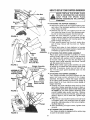
NOTE: To determine right and left hand sides of your
chipper-shredder, stand behind and face the hopper
(engine is at the front of the unit).
) ]
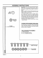
Your chipper-shredder
has been completely assembled at the factory, except for the hopper assembly
(hopper hood and upper leaf ramp section have been
sub-assembled), upper guide assembly, chute deflector and the catcher bag. The hardware pack and safety glasses are also included in the carton.
The hardware pack contains the parts shown in figure
1 (shown full size).
HeX Lock
ut 5/16-18
Thread
TOREMOVE
CHIPPER-SHREDDER
FROMCARTON
•,,----5/16-18
Cut the corners of the carton Remove all packing
inserts. Roll chipper-shredder out of the carton Make
certain all parts and literature have been removed
before the carton is discarded,
Hex Bolt
x 8-3/8" Long
TOOLSREQUIREDFORASSEMBLY
(1) Phillips Screwdriver
(2) 1/2" or Adjustable Wrenches
(2) 7/16" or Adjustable Wrenches
.oxLock
.ats
_=:
FIGURE 1.
_=VJ
V_
_'
_
'
1/4-20 Thread
HOWTOSET-UPYOURCHIPPER-SHREDDER
MAKE CERTAIN
THE SPARK PLUG]
WIRE IS DISCONNECTED AND MOVED
AWAY
FROM
THE SPARK
PLUG
BEFORE ASSEMBLING THE CHIPPERSHREDDER.
Bolt
Chute
Deflector
Hex
Nut
,.
_"-ATTACHING
Knob
J
\
/
/
FIGURE 2,
Stop
Washer
Upper
Guide
Assembly
Release
Bar
/
Place upper guide assembly in position on frame,
making certain edges of the upper guide assembly
are underrreath stop washers, and the release bar is
in the slots. See figure 3 Insert hex bolt 8-3/8" long
through upper guide assembly and frame_ Secure
with flat washer and hex lock nut
NOTE: Make certain upper guide assembly can pivot
by pulling up on release bar and lowering upper guide
assembly If necessary, loosen hex lock nut a turn or
two Put the upper guide assembly back into the
raised position
FIGURE 3.
ly
Leaf
Ramp
Section
Release"
Bar
Remove Truss
Screw and Nut
Guide
Assembly
FIGURE 4.
Drawstring
/
FIGURE 5.
THE HOPPER ASSEMBLY
e Remove the hand knobs and cupped washers from
each side of the discharge opening on the left side
of the chipper-shredder
e Remove hex lock nut, two spacers and hex bolt
from inside the hinge on top of the discharge opening Do not remove one spacer from the hex bolt.
e Place the chute deflector in position on the discharge opening Insert hex bolt and spacer' through
hinge on chute deflector and housing (spacer fits
inside of hinge) See figure 2.
e Place second spacer over hex bolt, inside other
part of hinge Secure with hex lock nuL Tighten
securely.
® Secure both sides of chute deflector to housing
using hand knobs and cupped washers (cupped side
of washers go against chute deflector)
"<,-ATTACHING THE UPPER GUIDE ASSEMBLY
8-3/8" Long
Flat Washer
Hex Lock Nut
Hopper Pivot
Door
ASSEMBLE THIS \
TRUSS SCREW
AND NUT FIRST
/
/
/
j
"<_-ATTACHING THE HOPPER ASSEMBLY
Your chipper-shredder
has been shipped with the
upper leaf ramp section attached to the hopper
assembly. See figure 4. Attach the hopper assembly
to the upper guide assembly as follows Be certain to
place heads of all truss machine screws inside of
hopper assembly.
® Remove one truss machine screw and nut from
each side of hopper assembly as shown in figure 4.
Push hopper pivot door down inside lower part
of hopper as you place hopper assembly (both
pieces) inside upper guide assembly
Replace
truss screws and nuts just removed, using the hote
shown in figure 4, one on each side. Tighten finger
tight only.
e Place the six truss machine screws and nuts found
in hardware pack in the remaining holes of hopper
assembly, alternating sides of the unit and tightening finger tight only.
® After' assembling all eight screws, tighten them
securely.
"<-ATTACHING THE CATCHER BAG
Your chipper-shredder is equipped with a catcher bag
to catch the shredded material
6
e To attach the bag, place the opening of the bag
over the chute deflector so it completely covers the
chute opening. Depress the plunger on the draw-
string, and pull on the drawstring until the bag is tight
around the chute opening Release plunger to lock it
into position, See figure 5,
OPERATION
KNOWYOURCHIPPER-SHREDDER
READ THIS OWNER'S MANUAL AND SAFETY RULES BEFORE OPERATING YOUR CHIPPER-SHREDDER
Compare the illustrations with your chipper-shredder to familiarize yourself with the location of various controls
and adjustments, Save this manual for future reference,
Hopper
Assembly
Oil Fill
Dipstick
Release
Bar
Chipper
Chute
Spark
Plug \
Chute
Deflector
Choke
Catcher
Bag
Throttle
Handle
FIGURE 6.
MEETSANSiSAFETYSTANDARDS
Sears chipper-shredders
conform to the safety standards of the American National Standards Institute_
OPERATING
CONTROLS(See
RELEASE BAR--Used
raising or lowering
CHOKE LEVER--Used
figure 6)
to release the hopper when
STARTER
engine,
to enrich the fuel mixture in
HANDLE--Used
to manually
THROTTLE CONTROL--Controls
stops the engine.
the carburetor when starting a cold engine.
start the
engine speed and
BEFORE USING YOUR CHIPPER-SHREDDER,
AGAIN REFER TO THE "SAFETY RULES" AS SHOWN ON
PAGE 2 OF THIS MANUAL, ALWAYS BE CAREFUL.
The operation of any chipper-shredder can result in foreign objects being thrown into
the eyes, which can result in severe eye damage. Always wear the safety glasses provided with the chipper-shredder or eye shields before chipping or shredding, or while
performing any adjustments or repairs_ We recommend Wide Vision Safety Mask for
over spectacles or standard glasses available at Sears Retail or Catalog Stores,
7
BEFORESTARTING
Caution: Experience indicates that alcohol blended
fuels (called gasohol or using ethanol or methanol)
can attract moisture which leads to separation and
formation of acids during storage Acidic gas can
damage the fuel system of an engine while in storage
To avoid engine problems, the fuel system should be
empty before storage for 30 days or longer Refer to
"Storage" section of this manual for details Use fresh
fuel each season.
Never use engine or carburetor cleaner products in
the fuel tank or permanent damage may result
GAS AND OIL FILL-UP
NOTE: ENGINE IS SHIPPED WITHOUT OIL FILL
CRANKCASE WITH OIL BEFORE STARTING. BE
VERY CAREFUL NOT TO ALLOW DIRT TO ENTER
THE ENGINE WHEN CHECKING OR ADDING OIL
OR FUEL
Recommended
SAE Viscosity
Grades
<llllll' 00!1o'w -%l
!,'T,,t _I_L_I.
!1[I
NOTE: USE CLEAN OIL AND FUEL. STORE IN
APPROVED,
CLEAN, COVERED CONTAINERS
USE CLEAN FILL FUNNELS.
-20 °
0°
32 °
60 °
80 °
100 °
TEMPERATURE
RANGE EXPECTED
BEFORE
NEXT OIL CHANGE
ALL OILS MUST BE API
SERVICE CLASSIFICATION SD, SE OR SF
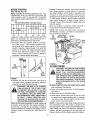
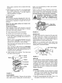
® Fill engine with oil as follows. Remove oil fill dipstick See figure 7 With chipper-shredder
level,
use a funnel to fill engine with oil to FULL mark on
dipstick Capacity is approximately 1-1/4 pints Be
careful not to overfill, Tilt chipper-shredder toward
the left (from behind the hopper'), then re-level
Check oil level Refill to FULL mark on dipstick if
necessary Replace dipstick and tighten.
Oil
Fill
Dipstick
Spark Plug,
Wire and Boot
Muffler
Fuel
Tank
FIGURE 8.
Oil
Fill.-----_
Dipstick
TO STARTENGINE
WARNING: BE SURE NO ONE OTHER
THAN THE OPERATOR IS STANDING
NEAR
THE
CHIPPER-SHREDDER
WHILE STARTING OR OPERATING, DO
NOT OPERATE THIS CHIPPER-SHREDDER UNLESS THE CHUTE DEFLECTOR
HAS BEEN PROPERLY
INSTALLED
AND IS SECURED
WITH THE HAND
KNOBS.
Oil
Drain
Plug
FIGURE 7.
® Remove fuel cap and fill fuel tank. See figure 8
Use fresh, clean, unleaded automotive gasoline.
Capacity is 3 quarts. Replace fuel cap
• Attach spark plug wire and rubber boot to spark
plug if necessary See figure 8
WARNING:
DO NOT FILL CLOSER
THAN 1/2 INCH OF TOP OF FUEL TANK
TO PREVENT SPILLS AND TO ALLOW
FOR FUEL EXPANSION. IF GASOLINE
IS ACCIDENTLY SPILLED, MOVE CHIPPER-SHREDDER
AWAY FROM AREA
OF SPILL.
AVOID CREATING
ANY
SOURCE OF IGNITION UNTIL GASOLINE VAPORS HAVE DISAPPEARED.
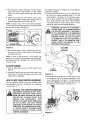
• Place the throttle
See figure 9.
control lever in FAST position.
e Move choke lever to CHOKE position
e Grasp starter handle (see figure 9) and pull rope
out slowly until engine reaches start of compression cycle (rope will pull slightly harder at this
point)_ Let the rope rewind slowly,
NOTE: A noise will be heard when finding the start of
the compression cycle. This noise is caused by the
flails and fingers which are part of the shredding mechanism falling into place, and should be expected In
addition, the flails and fingers will be noisy after the
engine is started, until the impeller reaches full speed.
Check the fuel level periodically to avoid running out
of gasoline wMle operating the chipper-shredder. If
the unit runs out of gas as it is shredding or chipping,
it may be necessary to unclog the unit before it can be
restarted, Refer to "Removing the Flail Screen" on
page 13
8
e Pull rope with a rapid, continuous, full arm stroke,
Keep a firm grip on start handle Let rope rewind
slowly Do not let starter handle snap back against
starter
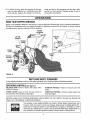
The chipper-shredder
is designed for three different
methods of operation
e Leaves and small branches up to 1/2" diameter can
be fed into the hopper assembly when it is in the
raised position See figure 10 If it becomes necessary to push material into the chipper-shredder,
use a small diameter stick--NOT YOUR HANDS
e Repeat preceding two instructions
until engine
fires When engine starts, move choke lever on
engine halfway between CHOKE and RUN
The stick should be small enough that it will be
ground up if gets into the impeller assembly
NOTE: If engine does not fire after three attempts,
move choke lever halfway between CHOKE and RUN
position and try again See figure 9
WARNING:
DO NOT PUT MATERIAL
LARGER THAN 1/2" IN DIAMETER INTO
THE HOPPER ASSEMBLY. MATERIAL
UP TO A MAXIMUM OF 3" IN DIAMETER
MATERIAL
MAY BE FED INTO THE
CHIPPER CHUTE. DO NOT ATTEMPT
TO SHRED OR CHIP ANY MATERIAL
LARGER THAN 3" IN DIAMETER. PERSONAL INJURY OR DAMAGE TO THE
MACHINE COULD RESULT.
,__
CI40_E
I
Throttle Control
\
FIGURE 9o
No Larger
Than 1/2"
e Move throttle control to IDLE position for a few minutes warm-up Move choke lever to RUN position
as engine warms up
NOTE: In order to idle smoothly, a new engine may
require 3 to 5 minutes running above slow idle speed
Idle speed has been adjusted to be correct after this
break-in period_
TO STOPENGINE
o Move throttle control lever to STOP position See
figure 9
Hopper
Assembly
e Disconnect spark plug wire and move away from
spark plug to prevent accidental starting while
equipment is unattended
FIGURE 10.
HOWTO USEYOURCHIPPER-SHREDDER
Do not attempt to shred or chip any material other
than vegetation found in a normal yard (i e, branches,
leaves, twigs, etc,)
WARNING: THE CHIPPER-SHREDDER
DISCHARGES MATERIALS WITH CONSIDERABLE
VELOCITY.
KEEP AWAY
FROM THE AREA AROUND THE CHUTE
DEFLECTOR.
ALWAYS
STOP THE
ENGINE
AND
DISCONNECT
THE
SPARK PLUG WIRE WHEN REMOVING
OR ATTACHING
THE BAG WHEN
CHANGING
CONTAINERS
OR WHEN
REMOVING THE SHREDDED MATERIAL. WEAR SAFETY
GLASSES
AND
GLOVES
WHENEVER
USING YOUR
CHIPPER-SHREDDER.
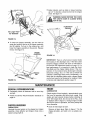
e Leaves and small twigs can be raked into the hopper assembly when the hopper assembly is lowered to the ground See figure 11 Small branches
up to 1/2" diameter can also be fed into the hopper assembly in this position See figure 12
FIGURE 11r
9
e Bulky material, such as stalks or heavy branches,
up to 3" in diameter, should be fed into the chipper
chute See figure 14
WARNING: MAKE CERTAIN THE CHIPPER CHUTE DOOR IS CLOSED WHEN
NOTINUSE.
3"Maximum
Diame_r
No
1/2" Diameter
FIGURE 12.
e To lower the hopper assembly, use one hand to
grasp the handle at the top of the hopper assembly
and lift slightly, Pull up on the release bar, and
lower the hopper assembly to the ground Release
the bar'. See figure 13.
Chipper
Chute
Hopper
Assembly
FIGURE 14.
IMPORTANT:
There is a flail screen located inside
the housing in the discharge area If the flail screen
becomes clogged, remove and clean as instructed in
the Service and Adjustments section on page 13 For
best performance, it is important to keep the shredding blade and the chipper blades sharp If the composition of the material being discharged changes
(becomes stringy, etc) or if the rate at which the
material is discharged slows down considerably, it is
likely that the shredding blade and/or chipper blades
are dull and need to be sharpened or replaced, Refer
to Service and Adjustments section, page 13.
Release
Bar
FIGURE 13.
MAINTENANCE
GENERALRECOMMENDATIONS
ENGINE
• Periodically
are tight.
LUBRICATION
check all fastener's and be sure they
® Follow the Service Recommendation
Check engine oil level regularly--approximately
every
five hours of operation and before each usage. Stop
engine and wait several minutes before checking oil
level With engine level, the oil must be to FULL mark
on dipstick (refer to figure 7). Change engine oil after
the first five hours of operation, and every twenty-five
hours thereafter
Schedule on
page 15.
CHIPPER-SHREDDER
• Drain oil while engine is warm.
LUBRICATION
Lubricate the pivot points on the release bar, hopper
assembly, chute deflector and chipper chute once a
season using a light off
Remove oil drain plug. Refer to figure 7_ Tip the
chipper-shredder, and catch oil ir} a suitable container
10
water is not recommended
When engine is drained of all oil, replace drain plug
securely_
nate the fuel system,
e Refill with fresh oil Above 32 °, use oil labeled SAE
30 or 10W30 Below 32 °, use oil labeled 5W20
Capacity is approximately
1-1/4 pints Refer to
"Gas and Oil Fill-Up" on page 8
Yearly or every 25
remove the blower
shown in figure 16 to
and engine damage
e Replace dipstick.
WARNING:
MUFFLER
AIR CLEANER
The air cleaner prevents damaging dirt, dust, etc,
from entering the carburetor and being forced into the
engine and is important
to engine life and performance
Never run your engine without
pletely assembled,
air cleaner
as water could contami-
GRASS,
DEBR S.
hours, whichever occurs first.
housing and clean the areas
avoid overspeeding, overheating
Clean more often if necessary
PERIODICALLY
CLEAN
AREA TO REMOVE
ALL
DIRT
AND
com-
COMBUSTIBLE
Clean Out
Chaff and Dirt
To Service Air Cleaner:
Clean cartridge at three month intervals or every 25
hours, whichever occurs first, See figure 15 Service
more often under dusty conditions.
e Loosen screws and tilt cover as illustrated
FIGURE 16.
e Carefully remove pre-cleaner and cartridge
SPARK PLUG
The spark plug should be cleaned and the gap reset
to 030" at least once a season or every 50 hours of
operation See figure 17 Spark plug replacement is
recommended at the start of each season, Refer to
engine parts list for correct spark plug type
e Clean cartridge by tapping gently on a flat surface
If very dirty, replace cartridge and pre-cleaner or
clean as follows:
Wash in a low or non-sudsing detergent and warm
water solution CAUTION: Do not use petroleum
solvents such as kerosene to clean cartridge
NOTE: Do not sandblast spark plug Spark plug
should be cleaned by scraping or wire brushing and
washing with a commercial solvent
Rinse thoroughly with flowing water from inside out
until water is clear
Allow cartridge to stand and air dry thoroughly
before using DO NOT OIL CARTRIDGE OR PRECLEANER DO NOT USE PRESSURIZED AIR TO
CLEAN OR DRY CARTRIDGE,
e Install cartridge and pre-cleaner
and fasten screws securely
.030" Feeler Gauge
\
Then close cover
Spark Plug
;crew
FIGURE '17.
MUFFLER
Do not operate the chipper-shredder without a muffler
or tamper with the exhaust system. Damaged mufflers
or spark arresters could create a fire hazard Inspect
periodically, and replace if necessary If your engine
is equipped with a spark arrester screen assembly,
remove every 50 hours for cleaning and inspection
Replace if damaged
ge
Base
CLEANING
® The chipper-shredder may be cleaned by running
water from a hose through the hopper assembly
and chipper chute with the engine running Allow
the chipper-shredder to dry thoroughly
FIGURE 15.
CLEAN ENGINE
Clean engine periodically
Remove dirt and debris
with a cloth or brush Cleaning with a forceful spray of
® Wash the bag periodically with water Allow to dry
thoroughly in the shade Do not use heat
11
STORAGE
NEVER
STORE
YOUR
CHIPPERAN EN-
any gasoline left in the tank to minimize gum deposits
and acids If the tank is almost empty, mix stabilizer
with fresh gasoline in a separate container and add
some to the tank Always follow instructions
on
stabilizer container. Then run engine at least 10
minutes after stabilizer is added to allow mixture
CLOSED, POORLY
VENTILATED
AREA
_SHREDDER
INDOORS
OR IN
IF GASOLINE REMAINS IN THE TANK.
FUMES MAY REACH AN OPEN FLAME,
SPARK OR PILOT' LIGHT FROM A FURNACE, WATER HEATER,
CLOTHES
DRYER, CIGARETTE, ETC.
to reach carburetor. Store chipper-shredder
safe place° See warning in previous column.
You can help keep your engine
condition during storage by:
To prevent engine damage if chipper-shredder is not
used for more than 30 days, follow the steps below
in
in good operating
e Changing oil
O
NOTE: GASOLINE
MUST BE REMOVED
OR
TREATED TO PREVENT GUM DEPOSITS FROM
FORMING IN THE TANK, FILTER, HOSE AND CARBURETOR DURING STORAGE
ALSO DURING
STORAGE, ALCOHOL-BLENDED
GASOLINE THAT
USES ETHANOL OR METHANOL
(SOMETIMES
CALLED GASOHOL) ATTRACTS WATER IT ACTS
ON THE GASOLINE TO FORM ACIDS WHICH DAMAGE THE ENGINE
Lubricating the piston/cylinder area by first removing the spark plug and squirting clean engine oil
into the spark plug hole Then cover' the spark plug
hole with a rag to absorb oil spray_ Next, rotate the
engine by pulling the starter two or three times
Finally, reinstall spark plug arrd attach spark plug
wire
Protect the chipper-shredder
during storage by:
e Thoroughly cleaning the chipper-shredder
e If storing in an unventilated or metal storage shed,
coat metal parts with a light oil or silicone to prevent rust
To remove gasoline, run engine until tank is empty
and engine stops Then disconnect fuel line at carburetor or fuel tank Be careful not to damage fuel line,
fittings or fuel tank Drain any remaining fuel from the
system If you do not want to remove gasoline, Sears
Craftsman Fuel Stabilizer No 33500 may be added to
e Store in a clean, dry area Do not store next to corrosive materials, such as fertilizer_
12
SERVKCE & ADJUSTMENT
NOTE: When reassembling, the cupped washer goes
on the bottom of the chipper chute with the cupped
side against the chute
WARNING:
ALWAYS
STOP ENGINE
AND DISCONNECT SPARK PLUG WIRE
AND MOVE IT AWAY FROM SPARK I
PLUG BEFORE
PERFORMING
ANY
ADJUSTMENTS OR REPA RS.
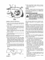
e Rotate the impeller assembly by hand until you
locate one of the chipper blades in the chipper
chute opening Remove the blade, using a 3/16"
allen wrench on the outside of the blade and 1/2"
wrench on the impeller assembly (inside the housing) See figure 19
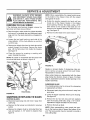
REMOVINGTHEFLAILSCREEN
If the discharge area becomes clogged, remove the
flail screen and clean area as follows
e Stop the engine, make certain the chipper-shredder
has come to a complete stop and disconnect spark
plug wire from the spark plug before unclogging the
chute
e Remove the other blade in the same manner
e Loosen the two hand knobs on each side of the
chute deflector
out of the way
Lift the chute deflector up, and tie it
e Remove two hairpin clips from the clevis pins which
extend through the housing Remove the clevis
pins Lift the flail screen from inside the housing
See figure 18
e Clean the screen by scraping
water Reinstall the screen
NOTE: Be certain to reassemble
or washing
with
the flail screen with
the curved side down as shown in figure 18.
Chute
@
Hairpin
Clips,
Clevis
Pins
FIGURE 19.
Replace or sharpen blades If sharpening, make certain to remove an equal amount from each blade,
Reassemble in reverse order
Make certain blades are reassembled with the sharp
edge facing the direction shown in figure 19 (sharp
edge is assembled toward the slotted opening in the
impeller assembly)
_Hex
Nuts
Washers
.Flail
Screen
SHREDDING
BLADE
The shredding blade may be removed for sharpening
or replacement as follows,
Chipper
Chute
® Disconnect spark plug wire and move it away from
spark plug
Hand Knobs
FIGURE 18.
SHARPENINGOR REPLACINGTHE BLADES
® Lower the hopper assembly, Block up the housing
See figure 20
CHIPPER BLADES
e Remove the six hex lock nuts and lock washers
from the housing weld bolts using a 1/2" wrench.
Separate the chipper-shredder into two halves.
® Disconnect spark plug wire and move it away from
spark plug.
® Remove the back-up plate
® Remove the flail screen as instructed in previous
section.
NOTE: When reassembling, make certain the opening on the back-up plate is toward the bottom of the
unit The back-up plate may be reversed to provide a
new cutting edge
® Remove the chipper chute by removing three hex
nuts and washers A 1/2" wrench is required, See
figure 18
13
e When reassembling the blade, tighten to between
550 and 650 inch pounds, or lacking torque
wrench, tighten securely
Allen
Screws
FLAILS
The flails, located
inside the housing,
may be
reversed when they become dull It is suggested that
this procedure be performed by your nearest Sears
Service Department
Pi
CARBURETOR
ADJUSTMENT
Sharp
of
WARNING: IF ANY ADJUSTMENTS
ENGINE
IS THE
RUNNING
(E.G.WHILE
CARBUREMAUE TO
ENGINE
THE
TOR), KEEP CLEAR OF ALL MOVING
PARTS. BE CAREFUL OF HEATED SURFACES AND MUFFLER.
Torque
Wrenctl
Minor carburetor adjustment may be required to compensate for differences in fuel, temperature, altitude
or load
FIGURE 2O,-Model 247.797853 Shown
e Loosen the two hand knobs and cupped washers
which secure the chute deflector, arrd raise the
chute deflector
NOTE: A DIRTY AIR CLEANER
WILL CAUSE
ENGINE TO RUN ROUGH
BE CERTAIN
AIR
CLEANER IS CLEAN AND ATTACHED TO THE
CARBURETOR
BEFORE ADJUSTING CARBURETOR DO NOT MAKE UNNECESSARY
ADJUSTMENTS FACTORY SETTINGS ARE SATISFACTORY FOR MOST APPLICATIONS AND CONDITIONS.
e Insert a 1/2" or 3/4" diameter pipe through the flail
screen into the impeller to keep it from turning, or
remove the flail screen and insert a piece of wood
(2 x 4) into the chute opening
e Model 247.797853 only: Remove the two outside
screws on the blade, using a 3/16" allen wrench
and a 1/2" wrench
The carburetor may need re-adjusting if engine lacks
power or does not idle properly If adjustments are
needed, proceed as follows
NOTE: Use caution when removing the blade to avoid
contacting the weld bolts on the housing
e When sharpening the blade, follow the original
angle of grind as a guide It is extremely important
that each cutting edge receives an equal amount of
grinding to prevent an unbalanced blade. An unbalanced blade will cause excessive vibration when
rotating at high speeds and may cause damage to
the unit.
e Close needle valve
( f-* ) finger tight only.
Then open 1-1/2 turns
e Start engine and allow
If engine idles, no further adjustment is necessary
/
,,
/
(see figure 22) clockwise
Forcing may cause damage
counterclockwise ( _ )
to warm for five minutes
e With throttle in FAST position, close needle valve
clockwise ( ,_ ) until engine starts to lose speed
(lean mixture)
Then slowly open needle valve
counterclockwise (f',)
until engine JUST BEGINS
to run unevenly
This mixture should be rich
enough for best performance under load.
e Place throttle control in IDLE position
e The blade can be tested for balance by balancing it
on a round shaft screwdriver or nail Remove metal
from the heavy side until it is balanced evenly See
figure 21
f
/
Never attempt to change maximum engine speed It is
pre-set at the factory and should be changed only by
a qualified service technician who has the necessary
equipment
e Remove the blade by removing the center bolt, lock
washer and flat washer
Na. \
ARE
If engine idles too fast, turn idle speed adjusting
screw counterclockwise ( _ ) until slower speed is
obtained
If engine dies, turn idle speed adjusting screw 1/4
Bl!de
'__1"
turn clockwise ( ,_ ). Place throttle control in FAS]_'
position and restart engine
--_j_
Move throttle control to IDLE position_ If engine
does not idle, repeat step c
FIGURE 21,
14
ENGINESPEED
• Test the engine by using the chipper-shredder
If
engine tends to stall or die out, it usually indicates
that the mixture is slightly lean and it may be necessary to open ( _ ) the needle valve slightly to
provide a richer mixture This richer mixture may
cause a slight unevenness in idling
Idle Speed
Adjusting Screw
Your engine speed has been factory set Do not
attempt to increase engine speed or it may result in
personal injury, If you believe the engine is running
too fast or too slow, take your chipper-shredder to the
nearest SEARS Service Center for repair and adjustment,
Throttle
Stop
Throttle
Needle Valve
FIGURE 22.
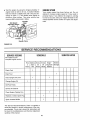
SERVaCE RECOMMENDATIONS
SERVICERECORD
SERVICE DATES
SCHEDULE
Fill in dates as you
complete regular service
First
5
Hours
Check Fuel
Before
Each
Use
Every
25
Hours
Every
Begin50
ning Each
Hours
Season
Before
Storage
,]
Drain Fuel
Check Engine Oil Level
Change Engine Oil
,1
.j
Oil Pivot Points
Service Air Cleaner
V
Clean Engine Cylinder Fins
,l
,/
Replace or Clean Spark Plug
,/
Spark Arrester Muffler
V
The Service Recommendations Chart is supplied to
assist the operator in proper maintenance of the chipper-shredder, This is only a check list; instructions will
be found in the Maintenance and Service Adjustment
sections of this manual
15
,]
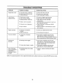
TROUBLE
SHOO'rING
PROBLEM
POSSIBLE CAUSE(S)
CORRECTIVE
Engine fails to start
e Fuel tank empty, or stale fuel
• Spark plug wire disconnected
e Faulty spark plug
e Fill tank with clean, fresh fuel
e Connect wire to spark plug
e Clean, adjust gap or replace
Loss of power;
operation erratic
e Spark plug wire loose
e Unit running on CHOKE
e Blocked fuel line or stale fuel
e Connect and tighten spark plug wire
e Move choke lever to OFF position
e Clean fuel line; fill tank with clean
fresh gasoline
e Disconnect fuel line at calburetor to d ]in fuel
tank Refill with fresh fuel
e Adjust carburetor or contact your SE.Z
Service Center
e Service air cleaner See Maintenance
of this manual
e Water or dirt in fuel system
e Carburetor out of adjustment
e Didy air cleaner
Engine overheats
e Carburetor not adjusted
properly
e Engine oil level low
ACTION
e Corrtact your SEARS Service Center
e Fill crankcase with proper oil
Too much vibration
e Loose parts or damaged
impeller
e
Unit does not
discharge
e Discharge chute clogged
e Stop engine immediately and disconn
spark plug wire Clean flail screen and inside
of blower housing See Service/Adjustments
section of this manual
e Stop engine immediately and discenn
spark plug wire. Remove lodged objec
•
Rate of discharge
slows considerably or
composition of
discharged material
changes
Foreign object lodged in impeller
e Shredding blade and/or chipper
blades dull
Stop engine immediately and disconn
spark plug wire Tighten all bolts errd i
Make all necessary repairs If vibration continues,
have unit serviced by a SEARS Service Center
e Sharpen or replace shredding and chi
blades
NOTE: For repairs beyond the minor adjustments listed above, please contact your nearest SEARS Service Center
16
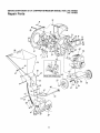
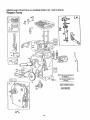
SEARS
CRAFTSMAN
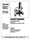
5 H.P. CHIPPER-SHREDDER
MODEL
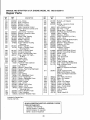
Repair Parts
NOS. 247.797852
247.797853
22
7
11
57
Model
59
17
35
36
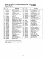
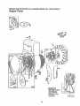
SEARS
CRAFTSMAN
5 H.R CHIPPER-SHREDDER
MODEL
NOS. 247.797852
Repair Parts
KEY
NO,
PART
NO,
13431
742-0571
710-0818
3
4
5
6
7
8
9
10
11
12
13
14
15
16
17
18
19
20
22
23
24
25
26
27
28
29
3O
31
32
33
34
35
36
247.797853
714-0114
736-0217
736-0247
11459B
711-0564
711-0833A
711-0834
715-0249
736-0192
781-0484
681-0002
781-0490
710-1054
712-0411
736-0119
710-0825
736-0142
750-0793
711-0835
712-0291
714-3010
781-0457
714-0149B
781-0480
712-3010
736-0242
720-0170
747-0744A
732-0542
781-0489
781-0475
736-0170
712-3010
781-0510
DESCRIPTION
Blade (247 797852)
Blade (247.797853)
Hex Patch Bolt 3/8-24 x 2" Lg
(Gr 8)
Sq. Key 1/4 x 2.0" Lg,
L-Wash 3/8" I.D HD.
FI-Wash 406"1D x 125"
OD Hdn
Flail
Flail Spacer
Clevis Pin .496" Dia
Flail Spacer w/160" Dia, Hole
Spring Roll Pin 1.12" Lg,
FI-Wash ,531" I.D. x .94" O,D
Impeller Ass'y (247.797852)
Impeller Ass'y (247,797853)
Chipper Blade
Flat Hd. Scr 5/16-24 x ,75" Lg
Hex Top L-Nut 5/16-24 (Gr, 5)
L-Wash. 5/16" ID*
Hex Bolt 1/4-20 x 375" Lg.*
FI-Wash 281" ID x.50" OD
Chute Hinge Spacer 1.66" Lg
Clevis Pin 5" Dia. x 462" Lg
Hex Ctr. L-Nut 1/4_20 Thd,
Cotter Pin
Shredder Screen
Internal Cotter Pin 3/8" Di&
Chute Deflector Ass'y,
Hex Nut 5/16-18 Thd (Gr. 5)
Bell-Wash ,345" I,D x 88"
Hand Knob
Chipper Door Rod
Torsion Spring 1.14" Lg
Chipper Door
Chipper Chute Ass'y
Spec, L-Wash, 5/16" ID,
Hex Nut 5/16-18 Thd (Gr 5)
Shredder Frame
*Common Hardware--May
NOTE: Specifications
notice or obligation
KEY
NO,
PART
NO,
DESCRIPTION
37
38
39
710-0157
736-0119
7t0-3008
40
41
42
43
44
45
46
47
48
710-0380
681-0004
781-0474A
735-0639
130212-3250-01
747-0531A
742-0546
712_0429
710-0601
49
50
51
52
53
54
55
56
11480
736-0264
710-0542
781-0487B
16522B
781-0494
16524B
710-0286
57
58
59
6O
61
62
63
64
65
66
67
68
----
712_0107
11461B
726-0214
736-0187
75O-O786
738-0814
734-1600
732-0629
747-0747
781-0492
781-0493
726-0106
764-0199A
723-0400
770-7110G
Hex Bolt 5/16-24 x _75" Lg,
L-Wash, 5/16" I.D,*
Hex Bolt 5/16-18 x 75" Lg
(Gr 5)
Hex Bolt 5/16-18 x 1.75" Lg*
Flail Housing Ass'y,--LH
Flail Housing Ass'y,--R H
Spark Plug Boot
Engine--B&S 130212-3250-01
Release Bar
Torsion Spring 1 06" Lg.
Elastic Lock Nut 5/16-18 Thd
Hex Wash Hd. Self-Tap Scr
5/16-t8 x .75" Lg
Stop Washer
Fl_Wash, 5/16" I.D
Hex Bolt 5/16-18 x 838" Lg
Back-Up Plate
Inlet Guide Ass'y
Pivot Hopper Hood
Upper Guide Ass'y
Truss Mach Scr 1/4-20 x _5"
Lg
Hex L-Nut 1/4-20 Thd
Upper Leaf Ramp Section
Push Cap 5/8" Di& Rod
FI-Wash. 64" I D x 1.24"
Spacer 64" I,D, x _38" Lg,
Shredder Axle
Wheel Ass'y Comp,
Torsion Spring
Hopper Door Rod
Hopper--Pivot Door
Hopper Lockout Brkt.
Cap Speed Nut 1/4" Rod
Bag (Not Shown)
Safety Glasses (Not Shown)
Owner's Manual
Be Purchased Locally
subject
to change
without
18
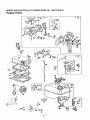
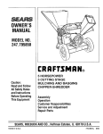
BRIGGS
AND STRATTON
5 H.P. ENGINE
MODEL
NO. 130212-3250-01
Repair Parts
26
7
337
36
35
741
16
615
230
SEE REPAIRINS'TRt_TION
MANUAL
219
46
220
(_22
19
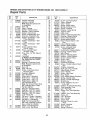
BRIGGS
AND STRATTON
5 H.P. ENGINE
MODEL
NO. 130212-3250-01
Repair Parts
3o5__
24
71
73
305
655
37
*REQUIRES
SPECIAL
TOOLS
TO INSTALL.
SEE REPAIR
INSTRUCTION
MANUAL=
2O
BRIGGS
AND STRATTON
5 H.P. ENGINE
MODEL
NO. 130212-3250-01
Repair Parts
127A
392
435
124
969
9
414 153
208
1012
190
191
96G{
153
527
725
529
_
526
209
11
21
BRIGGS
AND STRATTON
5 H.P. ENGINE
MODEL NO. 130212-3250-01
Repair Parts
KEY
NO,
PART
NO_
395990
297565
3
5
7
8
9
10
11
12
299819
211542
*272157
294178
*27549
93394i
665781
*270080
*270125
*270126
13
94221
14
93369
15
91249
16
492926
18
19
493916
297603
20
21
22
298504
66768
94607
23
24
25
297229
222698
298904
298905
298906
298907
26
29
298982
298983
298984
298985
26026
298909
298908
299430
30
31
221890
221876
27
28
DESCRIPTION
KEY
NO.
Cylinder Assembly
Bushing--Cylinder
Note: Requires special tools
for installation
Seal--Oil
Head--Cylinder
Gasket--Cylinder
Head
Breather--Valve Chamber
Gasket--Valve Cover
Screw--Breather Mtg. Sere
Grornmet--Breather
Tube
Gasket--Crankcase--.015"
Thick (Standard)
Gasket--Crankcase--005"
Thick
Gasket--Crankcase-009"
Thick
Screw--Cylinder
Head
(2_3/32" Long)
Screw--Cylinder
Head
(2-15/32" Long)
Plug--Pipe, 1/4" Std Square
Head
Crankshaft
To Replace Crankshaft Gear
Pin, Order Part No. 230978
Cover Ass'y
Bushing--Crankcase
Cover
Note: Requires special tools
for instatlation_
Seal--Oil
Plug--Oil Filler
Screw--Crankcase
Cover
Mounting Sere
Flywheel--Magneto
Key--Flywheel
Piston Ass'y --Standard
Piston Ass'y,-- 010" O,S,
Piston Ass'y.--.020" O S
Piston Ass'y.--.030" OS,
PISTON RING SETS:
Note: For Chrome Piston Ring
Set--Standard Size--Order
Part No 299742_
Ring Set--Standard Piston
Ring Set-- 010" O S. Piston
Ring Set--_020" O_S. Piston
Ring Set--.030" OS Piston
Lock--Piston Pin
Pin Ass'y,--Piston--Standard
Pin Ass'y --Piston--.005"
OS
Rod Ass'y --Connecting
Note: For Connecting Rod
with .020" undersize Crankpin
Bore--Order No, 390459.
Dipper--Connecting
Rod
Lock--Conn, Rod Screw
22
PART
NO,
32
33
34
35
36
37
40
45
46
52
55
56
57
58
92296
211119
261044
260552
26478
222443
93312
260642
212733
"271936
299431
295871
490179
66884
59
60
65
490653
490652
94128
66
67
68
70
71
73
74
75
90
95
399671
394897
63770
298799
394506
221923
93490
224061
492611
93499
96
97
108
118
124
127
127A
149
152
153
154
223793
490048
491177
23t 533
93357
220352
223789
26336
260575
490589
93527
163
180
181
190
271935
492927
490075
94094
191
200
201
202
203
204
*271928
223886
262280
262270
280720
222962
205
208
209
231520
262279
262288
DESCRIPTION
Screw--Connecting
Rod
Valve--Exhaust
Valve--Intake
Spring--Intake Valve
Spring--Exhaust Valve
Guard--Flywheel
Retainer--Valve Spring
Tappet--Valve
Gear--Cam
Gasket--Carburetor
Mounting
Housing--Rewind
Starter
Pulley--Rewind Starter
Spring-Rewind Starter
Rope--Rewind Starter--63"
Long
Insert--Starter Handle
Handle--Rewind Starter
Screw--Stamped
Steel
Housing Mtg. Sere
Clutch Ass'y--Rewind
Starter
Housing--Starter
Clutch
Ball--Clutch
Ratchet--Rewind
Starter
Washer--Clutch Retainer
Screen--Starter Pulley
Screw--Sem
Washer--Spring
Carburetor Assembly
Screw--Throttle Valve to Shaft
Sere
Throttle--Carburetor
Shaft and Lever--Throttle
Valve Group--Choke
ValvelNeedle
Screw--Hex
Head
Plug--Welch
Plug--Welch (Mixing Chamber)
Spring--Needle Valve
Spring--Throttle Adjustment
Screw Ass'y_
4,
Screw--Machine,
Rd. Hd.-5-40 x 5/8"
Gasket--Air Cleaner Mounting
Tank Assembly--Fuel
Cap--Fuel Tank
Screw--Fuel Tank Mounting
Sem
Gasket--Fuel Tank Mounting
Guide--Air
Link--Governor
Link--Throttle
Crank--Bell
Bushing--Governor
Lever
(Flat)
Screw--Shoulder
Rod--Control
Spring--Governor
BRIGGS
AND STRATTON
5 H.P. ENGINE
MODEL
NO. 130212-3250-01
Repair Parts
KEY
NO
PART
NO.
216
2t9
220
222
223
224
262359
391737
221551
490649
223455
93491
227
230
256
284
298
299
304
305
490374
222450
223813
94419
261409
393368
490169
94608'
306
307
221511
93758
308
333
335
337
221512
397358
93414
492167
346
356
358
363
93705
398808
397145
19069
373
383
392
394
414
432
433
434
435
441
467
523
524
525
526
92987
89838
262328
270026
220982
221377
93265
210959
93141
224240
280715
492249
271485
280508
94409
527
528
529
223786
231550
67838
DESCRIPTION
Link--Choke
Gear--Governor
Washer--Thrust
Bracket--Control
Lever--Governor
Control
Rivet--Governor Control Lever
Mounting
Lever Ass'y--Governor
Washer--Governor
Lever
Bell Crank
Screw--Self-Tapping
Lock Nut--Muffler
Muffler--Exhaust
Housing--Blower
Screw--Blower Housing
Mounting
Shield--Cylinder
Screw--Cylinder Shield
Mounting Sere
Cover--Cylinder Head
Armature Assembly
Screw--Armature
Mtg Sem
Plug--Spark 7/8" High-48 MM
Screw--Sem
Wire--Ground
Gasket Set
Flywheel Puller (Optional
Accessory)
Nut--Hex
Wrench--Spark
Plug
Spring--Fuel Pump Diaphragm
Diaphragm
Washer
Cap--Spring
Pin--Diaphragm Cover
Cover--Diaphragm
Screw--Diaphragm
Cover
Bracket--Oil Fill
Knob--Control
Cap--Oil Fill
Gasket--Oil Fill Cap
Nipple--Oil Fill
Screw--Tank Bracket
Mounting Sem
Clamp--Breather Tube
Tube--Breather
Grommet--Breather
Tube
KEY
NO.
PART
NO.,
535
542
552
491435
93572
231079
562
592
608
611
614
615
616
621
634
635
643
643A
655
676
92613
231O82
390463
391813
93306
93307
231077
396847
271853
66538
280737
280726
222598!
395700
679
680
725
741
779
842
847
851
869
870
270382
221839
223867
261696
262276
270920
493367
221798
211787
211172
871
262001
916
966
967
968
969
971
987
995
1012
1016
1019
280321
492797
491588
223765
490073
94018
398970
223887
490507
490817
491100
DESCRIPTION
Element--Air Cleaner
Screw
Bushing--Governor
Crank
(1/4" I D)
Bolt--Governor Lever
Nut--Hex --10-24
Starter Ass'y--Rewind
Fuel Pipe and Clip Assembly
Cotter--Hairpin
Retainer--E_Ring
Crank--Governor (1/4" Dia )
Switch--Stop
Washer--Throttle Shaft (Foam)
Elbow--Spark Plug
Retainer--Foam
Element
Retainer--Air Filter
Anchor Spring
Deflector--Exhaust
(Direct Outlet)
Washer Choke Shaft (Foam)
Washer Choke Shaft (Brass)
Shield--Heat
Gear--Timing
Link--Bell Crank
Seal--Tube
Oil Fill Ass'y
Cable Terminal--Ignition
Seat--Intake Valve (Standard)
Seat--Exhaust Valve
(Standard)
Note: For Options see Repair
Manual
Guide--Exhaust Valve
Note: 63709 Guide--Intake
Valve See Repair Instruction
Manual.
Gear Rack--Governor
Base--Air Cleaner
Filter--Air
Cover--Air Cleaner
Screw--Cover Mtg
Screw--Air Cleaner
Seal--Throttle Shaft
Bracket--Link
Link--Retainer
Spacer
Decal (Label) Kit
*Included in Gasket Set-Part No, 397145
SPARK ARRESTING MUFFLER ASSEMBLY 392390
(Optional Equipment)
Consists of the following:
392154 Screen (1 required)
223372 Deflector (1 required)
93705 Screw (4 required)
23
OWNER'S
MANUAL
5 HORSEPOWER
3 CUTTING STAGE
MULCHING AND BAGGaNG
CHBPPER-SHREDDER
Each chipper-shredder
has its own
engine has its own model number.
model
number.
The model number for your chipper-shredder
on a label attached to the frame_
The model number for the engine
blower housing of the engine.
will
Each
will be found
be found
on the
All parts listed herein may be ordered
through
Sears,
Roebuck and Co_ Service Centers and most Retail Stores.
WHEN ORDERING
REPAIR PARTS, ALWAYS
FOLLOWING INFORMATION:
HOWTOORDER
REPAIRPARTS
* PRODUCT-
"5 H.P. Chipper-Shredder"
* MODEL NUMBER
* ENGINE
GIVE THE
MODEL
- 247.797852
247.797853
NO. - 130212-3250-01
* PART NUMBER
* PART DESCRIPTION
Your Sears merchandise
has added value when you consider that Sears has service units nationwide
staffed with
Sears trained technicians...professional
technicians specifically trained on Sears products, having the parts, tools and
the equipment to insure that we meet our pledge to you__we
service what we sell/'
j
SEARS, ROEBUCK AND CO. , Chicago, IL
770-7110G
7/91
60684
U.S.A.
Printed in U.S,A.