1
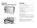
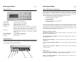
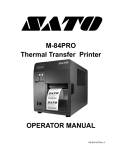
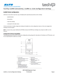
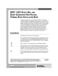
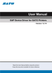
High-Speed, Wide Web
Format Printer
M-10e
(HQ)
(Japan)
(Singapore)
(Malaysia)
(Thailand)
(China)
(USA)
(Belgium)
(Germany)
(Poland)
(UK)
(Holland)
SATO International Pte Ltd
SATO Corporation
SATO Asia Pacific Pte Ltd
SATO Auto-ID Malaysia Sdn Bhd
SATO Auto-ID (Thailand) Co., Ltd
SATO Shanghai Co., Ltd
SATO America, Inc.
SATO Europe NV
SATO Deutchland GmbH
SATO Polska SP Z O.O.
SATO UK Ltd
SATO Rotterdam Logistic Center
Factory :
(Malaysia)
SATO Malaysia Sdn Bhd
Quick Guide
SATO Asia Pacific Pte Ltd
438A Alexandra Road
#05-01/02 Alexandra Technopark
Singapore 119967
Tel : (65) 6271 5300; Fax : (65) 6273 6011
Sales Hotline : (65) 6276 2722; Service Hotline : (65) 6273 6455
Email : [email protected]
Website : www.satoworldwide.com
© Copyright 2003
SATO Asia Pacific Pte Ltd
Warning : This equipment complies with the requirements in Part 15 of FCC rules for
a Class A computing device. Operation of this equipment in a residential area may
cause unacceptable interference to radio and TV reception requiring the operator to
take whatever steps necessary to correct the interference.
All rights reserved. No part of this document may be reproduced or issued to third
parties in any form whatsoever without the express permission of SATO Asia Pacific
Pte Ltd. The materials in this document are provided for general
information and are subject to change without notice. SATO Asia Pacific
Pte Ltd assumes no responsibilities for any errors that may appear.
S/APM-10e/QG/Jan03/01
M-10e Quick Guide
Pg 15
M-10e Quick Guide
Accessories & Options
PRINTER OVERVIEW
PCMCIA Memory Expansion
1 Slot for the PCMCIA Memory Card (up to 4MB SRAM or 16MB Flash ROM).
Can be used for graphic file storage, print buffer expansion, format storage and
downloaded fonts.
Calendar
An internal Date/Time clock that can be used to date/time stamp labels at the time of
printing
Label Cutter
An attachment allowing labels to be cut at specified intervals. Controlled through
programming
Label Unwinder
The Label Unwinder is an external mechanism that allows labels to be unwound from
a roll before they are being loaded into the printer for printing.
Stacker
This gadget stacks up printed labels neatly as they exit from the printer.
Coax/Twinax Interface
Coax/Twinax Plug-In Interface Module. Coax Interface emulates an IBM 3287-2
printer with a standard Type A BNC connector. Twinax interface emulates IBM 5224,
5225, 5226 or 4214 printers with auto-terminate/cable through capabilities.
Parallel Interface
IEEE1284 Bi-Directional Plug-In Interface Module
Serial Interface
High Speed RS232 Plug-In Interface Module
USB Interface
Universal Serial Bus Plug-In Interface Module
Ethernet Interface
10/100 BaseT Plug-In Interface Module
The SATO M-10e printer is a wide carriage thermal printer designed specifically to
address the need for large high-resolution labels. It can print labels as large as 10.5” x
16.5” with a resolution of 305dpi at speeds of up to 5” per second, making it ideal for
large compliance label applications. All printer parameters are user programmable
using the front panel controls and DIP switches. All popular barcodes and 14 human
readable fonts, including vector and 2 raster fonts, are resident in memory providing
various type styles and sizes.
The M-10e is available in 2 versions. The M-10eDT is a Direct Thermal only version
and must use thermally sensitive paper to print. The M-10eTT is a Thermal Transfer
model and has provisions for using a thermal transfer ribbon. It can also print in a
direct thermal mode if the ribbon is not used.
This Quick Guide is an extract of the more common functions which you need to start
the printer running. For more advance functions, please refer to the Operator Manual.
The M-10e uses the standard SATO Barcode Programming Language command
codes. The only difference between it and other SATO printers are the allowable
values representing the print positions on the label. These values are specified in
“dots” and vary depending upon the resolution of the printer and the amount of
memory available for imaging the label. The allowable ranges for the M-10e are
specified in the SATO “e” Printer Programming Reference. This commonality makes
it easy to convert labels from one SATO printer to another without having to create an
entirely different command stream. There are some caveats that must be observed,
though, to compensate for the different resolution print heads. The effects of the
different print resolutions are best illustrated by taking a label designed for a 305dpi
printer and sending the command stream to a 609dpi printer. The label printed will be
an exact ½ scale, including the fonts, barcode dimensions and line length/widths. The
only exceptions are the Postnet barcode and OCR-A and OCR-B fonts that have only
one legal size and the printer resolution is automatically compensated for by the
various printers. Conversely, a label designed for a 609dpi printer and sent to its
305dpi cousin will be twice as large. It probably will be “truncated” if the resulting
size is larger than the maximum allowable for the printer.
M-10e Quick Guide
Pg 1
Table of Contents
Installation ...………..…………………………………………………….….… 2
Installation ……………………………………………………….……. 2
Components …………………………………………………………… 3
Media Loading ………………………………………….……………………… 5
Ribbon Loading ….......……………………………..……………...….. 5
Label Stock Loading ...………………………………………………… 6
Operation Panel ……………...………………………………………………… 7
DIP Switch Panel ………………………………….…………………………… 7
Printer DIP Switch Configuration ……………………………………………. 8
RS232 Transmit/Receive Setting ……………………………………… 8
Printer Set Up …………………………………………………………. 8
Troubleshooting ……….……………………………………..………………… 10
Initial Checklist ..………………………………………………………. 10
Using the IEEE1284 Parallel Interface ………………………………… 10
Using the RS232C Serial Interface …………………………………….. 11
Using the USB Interface ……………………………………………….. 12
Using the LAN Eternet Interface ………………………………………. 12
Error Signals …………………………………………………………… 13
M-10e Specifications …………………………………………………………….14
Accessories & Options …………………………………………………………. 15
This Quick Guide was prepared to get you up and running quickly. It will enable you
to get your new SATO M-10e installed and printing with a minimum of effort.
However, it is recommended that you familiarise yourself with the contents of the
Printer’s Operator Manual for detailed descriptions so you will be able to properly
use the printer to its full potential.
M-10e Quick Guide
Pg 14
M-10e Specifications
SPECIFICATION
PRINT
Method
Speed (User Selectable)
Processor
Resolution
Maximum Print Length
Maximum Print Width
MEDIA
Width
Minimum Length
Roll OD (Maximum)
Label Sensing
RIBBON
Maximum Length
Widths
Thickness
PRINT-OUTS
Vector Fonts
Graphics
Bar Codes
Rotation
PHYSICAL
Dimension
Weight
POWER REQUIREMENTS
Voltage
Power Consumption
ENVIRONMENTAL
Operating
Storage
Optional Accessories
Options
Approvals
Safety / RFI/EMI
Thermal Transfer or Direct Thermal
3 – 5 ips (75 – 125 mm/s)
32-Bit RISC, 133MHz
305dpi (12 d/mm)
16.5” (420mm)
10.5” (266mm)
5.16” – 11.8” (131mm – 300mm)
1.7” (43mm)
7.8” (200mm), Wound Face-In
See-Thru, Reflective Eye-Mark, Continuous Forms
984ft (300m)
6.5” (165mm), 8.7” (220mm), 10.7” (273mm)
4.5 micron, Wound Face-In
Proportional or Fixed Spacing
Font Size 50 x 50 dots to 999 x 999 dots
Helvetica, 10 Font Variations
Dot Addressable, Sato Hex/Binary, .bmp or .pcx
19 including Four (4) 2-D Bar Codes
Text & Bar Codes can be rotated 90o, 180o & 270o
W18.7” x D12.3” x H12.6”
475mm x 313mm x 319mm
50.7 lbs (23 Kg)
Autoswitching 100-240V (± 10%); 60Hz (±1%)
40W Idle; 560W Operating
5 – 40oC; 30 – 80% RH, Non Condensing
-5 – 60oC; 30 – 90% RH, Non Condensing
Label Cutter; Real Time Clock; Memory Expansion;
Stacker; Label Un-winder
UL, CSA, TUV, FCC Class B
M-10e Quick Guide
Pg 13
Error Signals
Pg 2
Installation
Error
Condition
Machine Error
LED
LCD Message
Audible
Beep
Error On
Machine Error
1 Long
Error On
EEPROM Error
1 Long
EEPROM
Read/Write
Error On
Head Error
1 Long
Head
Error On
Sensor Error
3 Short
Sensor
Error Blinks
Card R/W Error
1 Long
Error Blinks
Card Low
Battery
1 Long
Error Blinks
Card No Battery
1 Long
Error Blinks
Head Open
3 Short
Head Open
Error Blinks
Cutter Error
3 Short
RS232 Parity
Error
Parity Error
3 Short
Cutter
Overrun Error
3 Short
Framing Error
3 Short
Buffer Over
3 Short
Error Blinks
Paper End
3 Short
Media End
Error Blinks
Ribbon End
3 Short
Ribbon End
Download Error
R/W Error
Mem Full Error
3 Short
Download
Error
CopyCard/Format
R/W Error
No Card Error
Mem Full Error
3 Short
Card Copy or
Format Error
Error On
Line Blinks
Error On
Line Blinks
Error On
Line Blinks
Error On
Line Blinks
M-10e Quick Guide
Memory Card
Read/Write
Memory Card
Battery Low
No Battery in
Card
RS232
Overrun Error
RS232
Framing Error
Buffer
Overflow
Possible Causes
Defective Board
1. EEPROM not installed
correctly
2. Overwriting EEPROM
Electrical Head malfunction
1. Paper Jam
2. Sensor DSW setting
3. Sensor level adjustment
1. Card not formatted
2. No card recognised
Card battery needs
replacement
Card needs battery installed
Remove the M-10e from its packing container. The Top Cover is shipped unattached
in a separate compartment. Check to make sure you have the following accessory
items:
Power Cord (Type varies country
to country)
Quick Guide
1. Head not latched
2. Head latch switch bad
1. Cutter Jam
2. Cutter Sensor Dirty
RS232 parameter mismatch
RS232 parameter mismatch
CD ROM
RS232 parameter mismatch
Command stream exceeds
buffer size
1. No Paper
2. Paper incorrectly loaded
1. Needs new ribbon roll
2. Ribbon sensor needs
adjustment
1. Read/Write error
2. Corrupted download file
3. Download file too large
1. R/W error during copying
2. Card not installed
properly
3. File too large
Cleaning Sheet
Careful consideration must be given when selecting the location of the printer,
especially to environmental considerations. To obtain optimum results from M-10e,
always try to avoid operation locations influenced by:
• Direct or bright sunlight, as this will make the label sensor less responsive
and may cause the label to be sensed incorrectly.
• Locations which have extremes of temperature, as this can create electrical
problems on the circuits within the printer.
• The installed location of the printer should ideally be in areas free from dust,
humidity and sudden vibrations.
Consumables
Always use SATO carbon ribbons and labels or equivalent in the thermal transfer
models. The use of incorrect materials may cause malfunctions of the printer and
void the printer warranty.
M-10e Quick Guide
Components
Pg 3
M-10e Quick Guide
Pg 12
Using the Universal Serial Bus (USB) Interface
If nothing prints when doing a test print, you will need to verify that the device drivers
have been successfully installed by doing the following:
1) Click on Start, then Settings and then Control Panel.
2) Within the new Window, you should have an Icon listed as System. Double click
on this.
3) Click on the Device Manager tab.
4) Make sure that the View Device by type is checked. Scroll down until you get to
SATO-USB device.
5) Verify that it does not have any errors next to it. If it shows an error, remove the
device and then reinstall it.
6) Reboot the PC and the Printer.
7) Consult the Windows Troubleshooting guide or contact your nearest SATO
Technical Support for more assistance.
Using the LAN Ethernet Interface
Printer Does Not Come Up Ready
If you cannot print to the print server after you have installed it, check the following:
1) Make sure that the printer is powered On, that all cables are securely plugged in,
and that the printer is On-Line.
2) If possible, connect a terminal to the serial port. If you see the boot prompt, the
print server firmware has not been loaded properly. If reloading does not fix the
problem, try setting switch 1 to ON (factory defaults) and powering the print
server Off and then On again; if the problem persists, the product may be
defective.
Installation Problems (Printer Comes Up Ready but you Cannot Print)
If the printer starts up OK, but you cannot print, the problem could be:
1) There is a problem with the interface between the print server and the printer.
2) There is a problem with the network connection or cabling.
3) There is a queue setup problem, a print server setup problem, or other protocolrelated problem.
M-10e Quick Guide
8.
Pg 11
M-10e Quick Guide
Pg 4
While checking the Hex Dump printout, if you notice 0DH0AH (Carriage Return
and Line Feed) characters throughout. The command string should be
continuous and no CR or LF characters are allowed between the Start Command
(<ESC>A) and the Stop Command (<ESC>Z). If you are using BASIC, it may
be adding these characters automatically as the line wraps. Adding a “width”
statement to your program can help to suppress these extra 0DH0AH characters
by expanding the line length up to 255 characters.
If you’re not programming in BASIC, check to see if you have an equivalent
statement in the language you’re using to suppress extra CR and LF from your
data being sent out to the printer. We want the data stream to be one complete
line going to the printer.
Using the RS232C Serial Interface
1)
2)
3)
4)
5)
6)
Is the RS232C Serial cable connected securely to your serial port on the PC
(DB25S or DB-9S Male) and to the RS232C connector on the printer?
Is the cable defective? At the very least, you should be using a “Null Modem
Cable”, which crosses pins in a specific manner. This should enable your printer
to print. But we recommend that you eventually use a cable built to
specifications as described in Section 6: Interface Specification of the Operator
Manual.
Is the RS232 Interface Module installed in the printer? The M-10e printers
require the new Hi Speed Serial Interface (PN WCL40451) to take advantage of
the faster data transmission speeds. The older Serial Interface Modules will
work, but at a reduced capability.
Check for obvious errors in the data stream. Is the data properly framed with the
<ESC>A and <ESC>Z commands?
If after sending your job to the printer, it only ‘beeps’ and displays an error
message on the LCD Display, you may have a configuration problem. There
may be some inconsistencies with the Baud Rate, Parity, Data Bits, or Stop Bits
in relation to your host computer. If you are confused as to what the printer’s
current RS232 settings are, print a Configuration Test label. It will list all of the
current printer configuration settings.
If you are still unable to get a printer output, try the Hex Dump as described in
Step 5 under the Parallel Interface troubleshooting. In this case, the printer
monitors the RS232C interface for incoming data.
Power Switch
To turn power On or Off
Operator Panel
To set up the various configurations and to display dispensing
quantity and the various alarms
Configuration Panel
Potentiometers and DIP switches to configure the printer and
make setup adjustments
AC Input Connector
To input 115 ~ 240V 50/60 Hz. Use the power cable provided
Interface Slot
Slot for installation of Plug-In Interface Module
EXT Connector
This is an external signal connector for external control of print
cycle
PCMCIA Card Slot
Connector for Optional PCMCIA Memory Card
M-10e Quick Guide
Pg 5
M-10e Quick Guide
Media Loading
Troubleshooting
Ribbon Loading (not applicable for the M-10e DT)
Initial Checklist
1. Open the Top Cover to expose the ribbon
mechanism…
2. Open the Print Head by pulling forward on the
purple Head Latch lever on the right hand side of
the ribbon mechanism.
3. Lift the Print Head by rotating it upwards and to
the rear.
4. The right hand Ribbon Supply Spindle is spring
loaded. Press outward on the spring loaded spindle
and place the new ribbon on the left hand spindle,
making sure the notches in the core line up with
the tangs on the spindle.
5. Place the ribbon on the right hand ribbon Supply
Spindle, again making sure the notches in the core
line up with the tangs on the spindle. Release the
spring loaded spindle.
6. Route the ribbon around the Print Head and up to
the take up core as shown in the ribbon loading
diagram in the Top Cover.
7. Place an empty ribbon core on the Ribbon Take Up
Spindle. The right hand spindle is spring loaded.
Press outward to provide clearance to install the
core. The ribbon leader is attached to the ribbon
by an adhesive strip. Carefully pull the leader free
and pull about 18” of leader from the new ribbon.
The ribbon should come off the top of the roll, ink
side (dull side) down.
8. Route the ribbon as shown in the Ribbon Routing
Diagram on the inside of the Top Cover.
9. Attach the leader to the take up core by pressing
the adhesive strip on the leader firmly onto the
core (if the adhesive strip does not adhere, use a
small piece of tape).
10. Manually wind approximately 3 turns of ribbon on
the core.
11. Inspect the ribbon to make sure it is not folded over or excessively wrinkled as it
passes over the print head.
12. Close the Print Head by rotating it forward and down. Press firmly on each end of
the ribbon mechanism at the points labelled “PUSH” until the Print Head latches
firmly in place.
1.
2.
3.
Pg 10
Is the printer powered up and ON-LINE?
Is the ERROR light on the front panel off? If this light is on, it may mean the
Print Head Assembly or the Label Hold-Down is not closed and latched in
position
Are the LABEL and RIBBON lights on the front panel off? If the lights are on,
the labels or ribbon may be incorrectly loaded.
Using the IEEE1284 Parallel Interface
1.
2.
3.
4.
5.
6.
7.
Is the IEEE1284 printer cable connected securely to your parallel port (DB-25S
Female) on the PC and to the Parallel Interface connector on the printer?
Does the parallel interface cable used meet IEEE1284 specifications? If it does
not and you are connected to an IEEE1284 or ECP parallel port on the computer,
the printer may not be able to communicate correctly.
Is there more than 1 parallel interface port on your PC (LPT1, LPT2, etc)? If so,
make sure you are sending data out the correct port.
Is the IEEE1284 Interface Module installed in the printer? Older versions of the
Parallel Interface module will not work correctly in the “Se” printers.
When you send the print job to the printer, and it does not respond, do you get an
error message on your PC that says “Device Fault” or something similar?
This may mean that the computer does not know the printer is there. Verify that
a) Both ends of the cable are securely inserted into their respective
connectors.
b) The printer is ONLINE.
c) The cable is not defective. There are other things that can cause this error
message on your computer, but at this stage, a defective cable may be one
of the reasons.
When you send the print job to the printer and it does not respond, and there is
no error message on the PC:
a) Check your data stream for some of the basics. Is your job framed as
follows? <ESC>A—DATA—<ESC>Z
b) Verify that you have included all required parameters in the data stream
c) Verify the following :
i) You have not typed a ‘0’ (zero) for an ‘O’ (letter) or vice versa
ii) You have not missed any <ESC> characters where they’re needed
iii) Make sure all printer command codes are Capital Letters
If you’ve checked all of the above and the printer still isn’t printing, you may
want to try a Buffer Hex Dump to determine what (if anything) the printer is
receiving from your computer.
M-10e Quick Guide
Pg 9
M-10e Quick Guide
Pg 6
Label Stock Loading
Head Check Selection (DSW2-3) – When selected, the printer will check for head
elements that are electrically malfunctioning.
Hex Dump Selection (DSW2-4) – Selects Hex Dump mode.
Receive Buffer Selection (DSW2-5) – Selects the operating mode of the receive
buffer.
Firmware Download (DSW2-6) – Places the printer in the Firmware Download
mode for downloading new firmware into the flash ROM.
Protocol Code Selection (DSW2-7) – Selects the command codes used for protocol
control.
Status Select (DSW2-8) – For emulating earlier series software commands. Should
be used only if problems are encountered when using existing software. This switch
will also affect the settings selected by DSW1-7 and DSW1-8.
Backfeed Sequence (DSW3-1, DSW3-2) – Backfeed is used to correctly position the
label for application and then retract the next label to the proper print position. This
operation can be performed immediately after a label is printed and used, or
immediately prior to the printing of the next label.
Label Sensor Selection (DSW3-3) – Enables or disables the Label Sensor. If the
Sensor is enabled, it will detect the edge of the label and position it automatically. If
it is disabled, the positioning must be under software control using Line Feed
commands.
Back-Feed Selection (DSW3-4) – When Back-Feed is enabled, the printer will
position the last printed label for dispensing and retract it before printing the next
label. The amount of backfeed offset is adjustable.
EXT Print Start Signal Selection (DSW3-5) – Allows an external device to initiate a
label print for synchronisation with the applicator. When DSW3-5 is On, the unit is in
the Continuous print mode, Backfeed is disabled and External Signals are ignored.
External Signal Type Selection (DSW3-6, DSW3-7) – Both the polarity and signal
type (level or pulse) of the external print synchronising signal can be selected.
Repeat Print via External Signal (DSW3-8) – Allows the applicator to reprint the
current label in the print buffer.
The M-10e has an automatic media loading feature, making it extremely easy to load.
1. Select the proper media sensing method
using the DIP switches on the Configuration
Panel. The printer comes from the factory
set up for label gap detection (DS2-2 and
DS3-3 both in the Off position). If EyeMark labels are to be used, DS2-2 should be
placed in the On position.
2. Apply power to the printer.
3. Release the Print Head by pulling forward
on the Head Latch Lever.
4. Check to make sure that nothing is in the
media path. Remove any media that may
have been left in the printer.
5. Adjust the Label Width Guides by loosening
the thumbscrew and moving the guides in or
out to match the media width. The guides
are interlocked so that adjusting one will
automatically adjust the other side to
maintain a centre justified label path.
Tighten the thumbscrews.
6. Note that the Green Media Loaded LED on
the back panel is off.
7. Thread the media into the back of the printer
between the label guides. When it is
correctly positioned, the Green Media
Loaded LED will be on.
8. Close the Top Cover.
9. Place the printer Online by pressing the
LINE key.
10. The printer will automatically feed the media
into the printer until it is correctly positioned
for printing.
M-10e Quick Guide
Pg 7
Operation Panel
LCD Display
POWER LED
ERROR LEDs
ON-LINE LED
LINE Key
FEED Key
RIGHT CURSOR >>
LEFT CURSOR <<
ENTER
M-10e Quick Guide
Pg 8
Printer DIP Switch Configuration
2 Lines x 16 Character display
Illuminated when power is applied
Illuminated when errors occur
Illuminated when printer is On-Line
Switches the printer On-Line or Off-Line. It can also be
used as a Pause function key to stop label during the
printing process. Also used as an UP cursor control
To feed 1 blank label. When On-Line, the printer will print
another copy of the last label. Also used as a DOWN
cursor control
To move the cursor to the right
To move the cursor to the left
Selects setting
DIP Switch Panel
The DIP Switch Panel is located inside the cover and contains two 8-position DIP
switches and four adjustment potentiometers.
There are two DIP switches (DSW2 & DSW3) located on the left side of the printer
under a flip-up cover. Raise the Top Cover for access to these switches. In addition,
a third DIP switch is located on the RS232C Serial Adapter card and is used to set the
RS232C transmit/receive parameters. These switches can be used to set:
8. Thermal Transfer of Direct Thermal Mode
9. Label Sensor Enable / Disable
10. Head Check Mode
11. Hex Dump Mode
12. Single Job or Multi-Job Receive Buffer
13. Operation Mode
Each switch is an eight section toggle switch. The ON position is always to the left.
To set the switches, first power the unit Off, then position the DIP switches. Finally,
after placing the switches in the desired positions, power the printer back On. The
switch settings are read by the printer electronics during the power up sequence. They
will not become effective until the power is cycled.
RS232 Transmit/Receive Setting
Data Bit Selection (DSW1-1) - This switch sets the printer to receive either 7 or 8 bit
data bits for each byte transmitted.
Parity Selection (DSW1-2, DSW1-3) – These switches select the type of parity used
for error detection.
Stop Bit Selection (DSW1-4) – Selects the number of stop bits to end each byte
transmission.
Baud Rate Selection (DSW1-5, DSW1-6) – Selects the data rate (bps) for the RS232
port.
Protocol Selection (DSW1-7, DSW1-8) – Selects the flow control and status
reporting protocols.
Printer Set Up
Print Mode Selection (DSW2-1) – Selects between direct thermal printing on
thermally sensitive paper and thermal transfer printing using a ribbon.
Sensor Type Selection (DSW2-2) – Selects between the use of a label gap or a
reflective Eye-Mark detector