1
INVERTER
Plug-in option
FR-A7AX
FR-A7AX E kit
INSTRUCTION MANUAL
16-bit digital input function
PRE-OPERATION INSTRUCTIONS
INSTALLATION AND WIRING
(FR-A700/F700 SERIES)
INSTALLATION AND WIRING
(FR-E700 SERIES (E kit))
1
2
3
CONNECTION DIAGRAM AND TERMINAL
4
PARAMETERS
5
Thank you for choosing this Mitsubishi Inverter plug-in option.
This instruction manual gives handling information and
precautions for use of this equipment. Incorrect handling might
cause an unexpected fault. Before using the equipment, please
read this manual carefully to use the equipment to its optimum.
Please forward this manual to the end user.
This section is specifically about
safety matters
Do not attempt to install, operate, maintain or inspect this
product until you have read through this instruction manual and
appended documents carefully and can use the equipment
correctly. Do not use this product until you have a full
knowledge of the equipment, safety information and
instructions.
In this instruction manual, the safety instruction levels are
classified into "WARNING" and "CAUTION".
WARNING
CAUTION
Assumes that incorrect handling may
cause hazardous conditions, resulting
in death or severe injury.
Assumes that incorrect handling may
cause hazardous conditions, resulting
in medium or slight injury, or may
cause physical damage only.
CAUTION level may lead to a serious
Note that even the
consequence according to conditions. Please follow the
instructions of both levels because they are important to
personal safety.
SAFETY INSTRUCTIONS
1. Electric Shock Prevention
WARNING
• While power is ON or when the inverter is running, do not
open the front cover. You may get an electric shock.
• Do not run the inverter with the front cover or wiring cover
removed. Otherwise, you may access the exposed highvoltage terminals and charging part and get an electric shock.
• If power is OFF, do not remove the front cover except for
wiring or periodic inspection. You may access the charged
inverter circuits and get an electric shock.
• Before starting wiring or inspection, check to make sure that
the indication of the inverter operation panel is OFF, wait for at
least 10 minutes after the power supply has been switched
OFF, and check that there are no residual voltage using a tester
or the like. The capacitor is charged with high voltage for some
time after power OFF and it is dangerous.
• Any person who is involved in the wiring or inspection of this
equipment should be fully competent to do the work.
• Always install the plug-in option before wiring. Otherwise,
you may get an electric shock or be injured.
• Do not touch the plug-in option with wet hands. Otherwise
you may get an electric shock.
• Do not subject the cables to scratches, excessive stress,
heavy loads or pinching. Otherwise you may get an electric
shock.
A-1
2. Injury Prevention
3) Usage
WARNING
CAUTION
• Apply only the voltage specified in the instruction manual to
each terminal. Otherwise, burst, damage, etc. may occur.
• Ensure that the cables are connected to the correct terminals.
Otherwise, burst, damage, etc. may occur.
• Always make sure that polarity is correct to prevent damage, etc.
Otherwise, burst, damage may occur.
• While power is ON or for some time after power-OFF, do not
touch the inverter as it is hot and you may get burnt.
3. Additional Instructions
Also note the following points to prevent an accidental failure,
injury, electric shock, etc.
1) Transportation and mounting
CAUTION
• Do not install or operate the plug-in option if it is damaged or
has parts missing.
• Do not stand or rest heavy objects on the product.
• Check that the mounting orientation is correct.
• Prevent other conductive bodies such as screws and metal
fragments or other flammable substance such as oil from
entering the inverter.
2) Trial run
CAUTION
• When parameter clear or all parameter clear is performed,
reset the required parameters before starting operations.
Each parameter returns to the initial value.
• For prevention of damage due to static electricity, touch
nearby metal before touching this product to eliminate static
electricity from your body.
4) Maintenance, inspection and parts replacement
CAUTION
• Do not test the equipment with a megger (measure insulation
resistance).
5) Disposal
CAUTION
• Treat as industrial waste.
CAUTION
• Before starting operation, confirm and adjust the parameters.
A failure to do so may cause some machines to make
unexpected motions.
A-2
• Do not modify the equipment.
• Do not perform parts removal which is not instructed in this
manual. Doing so may lead to fault or damage of the inverter.
6) General instruction
All illustrations given in this manual may have been drawn with
covers or safety guards removed to provide in-depth
description. Before starting operation of the product, always
return the covers and guards into original positions as specified
and operate the equipment in accordance with the manual.
— CONTENTS —
1
PRE-OPERATION INSTRUCTIONS
1.1
Unpacking and Product Confirmation .............................................................................................1
1.1.1
1.1.2
1.2
1.3
2
Product confirmation (FR-A700/F700 series) ................................................................................................. 1
Product confirmation (FR-E700 series (E kit))................................................................................................ 2
Parts ....................................................................................................................................................3
Specifications.....................................................................................................................................4
INSTALLATION AND WIRING (FR-A700/F700 SERIES)
2.1
2.2
2.3
Wiring of FR-A7AX ......................................................................................................................................... 8
Wiring at inverter side................................................................................................................................... 10
INSTALLATION AND WIRING (FR-E700 SERIES (E kit))
3.1
3.2
3.3
4.1
4.2
4.3
12
Pre-Installation Instructions ...........................................................................................................12
Installation Procedure .....................................................................................................................12
Wiring................................................................................................................................................17
3.3.1
3.3.2
4
5
Pre-installation instructions .............................................................................................................5
Installation procedure .......................................................................................................................6
Wiring..................................................................................................................................................8
2.3.1
2.3.2
3
1
Wiring of FR-A7AX ....................................................................................................................................... 17
Wiring of inverter .......................................................................................................................................... 19
CONNECTION DIAGRAM AND TERMINAL
20
Connection Diagram........................................................................................................................20
Internal Block Diagram....................................................................................................................22
Terminals ..........................................................................................................................................23
I
4.4
5
Code Input Example ........................................................................................................................24
PARAMETERS
5.1
5.2
Parameter List ..................................................................................................................................25
Parameter Setting ............................................................................................................................27
5.2.1
5.2.2
5.2.3
5.2.4
5.2.5
5.2.6
5.3
II
25
Selection of input method (Pr. 304) (FR-A700/F700 SERIES)..................................................................... 27
Selection of input method (Pr. 304) (FR-E700 series).................................................................................. 28
Read timing operation selection (Pr. 305) .................................................................................................... 29
Bias and gain adjustment (Pr. 300, Pr. 301, Pr. 302, Pr. 303) ..................................................................... 31
Digital input unit selection (Pr. 329).............................................................................................................. 34
16-bit digital torque command (FR-A700 series only) .................................................................................. 35
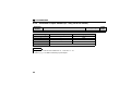
Instructions ......................................................................................................................................39
1
1.1
PRE-OPERATION INSTRUCTIONS
Unpacking and Product Confirmation
Take the plug-in option out of the package, check the product name, and confirm that the product is as you
ordered and intact.
FR-A7AX is a plug-in option for the FR-A700/F700/E700 series.
1.1.1
Product confirmation (FR-A700/F700 series)
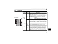
Check the enclosed items.
Plug-in option
Mounting screw (M3 × 6mm) Hex-head screw for option
......................................... 1 .............. 2 (Refer to page 6.) mounting (5.5mm)
............... 1 (Refer to page 6.)
5.5mm
1
1
PRE-OPERATION INSTRUCTIONS
1.1.2
Product confirmation (FR-E700 series (E kit))
Check the enclosed items.
Plug-in option
.............................................. 1
Mounting screw (M3 × 6mm)
................ 2 (Refer to page 14, 16)
Option small cover *2
Front cover for plug-in option
Option protective cover *1
................. 1 (Refer to page 14, 15) ..................... 1 (Refer to page 14) ......................1 (Refer to page 15)
*1
*2
Used with the FR-E720-3.7K (FR-E720-175) or less and FR-E740-7.5K (FR-E740-170) or less.
Used with the FR-E720-5.5K (FR-E720-240) or more and FR-E740-11K (FR-E740-230) or more.
CAUTION
• Install a provided front cover for plug-in option, in place of the inverter front cover.
2
PRE-OPERATION INSTRUCTIONS
1.2
Parts
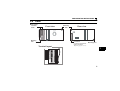
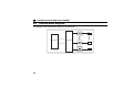
z FR-A7AX
Terminal
block
Mounting
hole
Front view
Mounting
hole
Connector
Connect to the inverter
option connector
(Refer to page 6, 13, 15.)
Terminal layout
X10
X11
X12
X13
X14
X15
DY
Rear view
Mounting hole
1
X0
X1
X2
X3
X4
X5
X6
X7
X8
X9
3
PRE-OPERATION INSTRUCTIONS
1.3
Specifications
(1) Digital input signal type
BCD code 3-digit or 4-digit
Binary 12-bit or binary 16-bit
(2) Selection of digital input signal
Select from the operation panel or parameter unit.
(3) Input current
5mA(24VDC) for each circuit
(4) Input specifications
Relay contact signal or open collector input
(5) Adjustment function
⋅ Bias and gain
⋅ Analog compensation input (They can be set for the FR-A700/F700 series only.)
(Set using the operation panel)
4
2
INSTALLATION AND WIRING (FR-A700/F700 SERIES)
2.1
Pre-installation instructions
Make sure that the input power of the inverter is OFF.
CAUTION
With input power ON, do not install or remove the plug-in option. Otherwise, the inverter and
plug-in option may be damaged.
For prevention of damage due to static electricity, touch nearby metal before touching this
product to eliminate static electricity from your body.
2
5
INSTALLATION AND WIRING (FR-A700/F700 SERIES)
2.2
Installation procedure
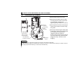
1) Remove the inverter front cover.
1)
2) Mount the hex-head screw for option
mounting into the inverter screw hole
(on earth plate). (size 5.5mm,
tightening torque 0.56N⋅m to 0.75N⋅m)
Screw hole for
option mounting
Inverter side
option
connector
3)
Screw hole for
option mounting
(on earth plate)
Hex-head screw
for option mounting
2)
4) Mounting
3) Securely fit the connector of the plug-in
option to the inverter connector along
the guides.
4) Securely fix the both right and left sides
of the plug-in option to the inverter with
the accessory mounting screws .
(Tightening torque 0.45N⋅m to
0.55N⋅m) If the screw holes do not lineup, the connector may not have been
plugged securely. Check for loose
plugging.
screws
REMARKS
• Remove a plug-in option after removing two screws on both left and right sides.
(When the plug-in option is mounted in the connector 3 (connector 1 for the FR-F700 series), it is easier to remove
the plug-in option after removing a control circuit terminal block.)
6
INSTALLATION AND WIRING (FR-A700/F700 SERIES)
CAUTION
•
•
Only one type of option per inverter may be used. When two or more options are mounted, priority is in the
order of inverter option connectors 1, 2 and 3. The options having lower priority are inoperative.
When the inverter cannot recognize that the option is mounted due to improper
Mounting
Error
installation, etc., "
to
" (option fault) are displayed for the FRPosition
Display
A700 series. The errors shown differ according to the mounting positions
Connector 1
(connectors 1, 2, 3).
Connector 2
Connector 3
• •The
•
•
FR-F700 series has one connection connector for the plug-in option. When
the inverter can not recognize that the option unit is mounted due to improper installation, etc., "
(option fault) is displayed.
Take caution not to drop a hex-head screw for option mounting or mounting screw during mounting and
removal.
Pull out the option straight to remove. Otherwise, the connector may be damaged.
"
2
7
INSTALLATION AND WIRING (FR-A700/F700 SERIES)
2.3
Wiring
2.3.1
Wiring of FR-A7AX
Untwist the twisted pair shielded cables after stripping its sheath.
Shield
Also, perform protective treatment of the shield to ensure that it will not
(perform protective treatment)
make contact with the conductive area.
Sheath
Strip off the sheath for the below length. If the length of the sheath peeled
is too long, a short circuit may occur with neighboring wires. If the length
is too short, wires might come off.
Wire the stripped cable after twisting it to prevent it from becoming loose.
(Do not solder it.)
Cable stripping length
5mm
Use a blade type terminal as required.
8
Twisted pair
shielded cable
INSTALLATION AND WIRING (FR-A700/F700 SERIES)
REMARKS
• Information on blade terminals
Commercially available product examples (as of March 2008)
Terminal
Screw Size
Wire Size
(mm2)
M2
0.3, 0.5
Blade Terminal Model
With insulation sleeve Without insulation sleeve
AI 0,5-6WH
A 0,5-6
Maker
Phoenix Contact
Co.,Ltd.
Blade terminal crimping tool: CRIMPFOX ZA3 (Phoenix Contact Co., Ltd.)
Insert wires to a blade terminal, and check that the wires come out for about 0 to 0.5 mm from a sleeve.
Check the condition of the blade terminal after crimping. Do not use a blade terminal of which the crimping is
inappropriate, or the face is damaged.
ll
he
Unstranded
wires
ire
W
S
e
ev
m
.5m
o0
t
0
e
Sl
Damaged
Wires are not inserted
into the shell
Crumpled tip
2
(1) Loosen the terminal screw and insert the cable into the terminal.
Screw Size
Tightening Torque
Cable Size
Screwdriver
M2
0.22N⋅m to 0.25N⋅m
0.3mm2 to 0.75mm2
Small
flat-blade screwdriver
(Tip thickness: 0.4mm/tip width: 2.5mm )
CAUTION
• Undertightening can cause cable disconnection or malfunction. Overtightening can cause a short circuit or
malfunction due to damage to the screw or unit.
9
INSTALLATION AND WIRING (FR-A700/F700 SERIES)
2.3.2
Wiring at inverter side
For wiring of the inverter with one front cover, route wires between the control circuit terminal block
and front cover. If cables can not be routed between the control circuit terminal block and front cover
due to the increased number of cables, remove a hook of the front cover and use a space become
available.
For wiring of the inverter which has front cover 1 and 2, use the space on the left side of the control
circuit terminal block.
Cut off
with a
nipper,
etc.
Front cover
Cut off a hook on the inverter
front cover side surface.
(Cut off so that no portion is left.)
Inverter with one front cover
Front cover 1
Front cover 2
Control circuit
terminal block
Inverter which has front cover 1 and 2
REMARKS
• When the hook of the inverter front cover is cut off for wiring, the protective structure (JEM1030) changes to open
type (IP00).
10
INSTALLATION AND WIRING (FR-A700/F700 SERIES)
CAUTION
When performing wiring using the space between the inverter front cover and control circuit
terminal block, take caution not to subject the cable to stress.
After wiring, wire offcuts must not be left in the inverter. These may cause a fault, failure or
malfunction.
2
11
3
INSTALLATION AND WIRING (FR-E700 SERIES (E kit))
3.1
Pre-Installation Instructions
Make sure that the input power of the inverter is off.
CAUTION
With input power on, do not install or remove the plug-in option. Otherwise, the inverter and
plug-in option may be damaged.
For prevention of damage due to static electricity, touch nearby metal before touching this
product to eliminate static electricity from your body.
3.2
Installation Procedure
The FR-E700 series has one connection connector for the plug-in option.
CAUTION
•
•
•
•
Always perform wiring to the main circuit terminals and control circuit
terminals before installing the option. Wiring cannot be performed after
installing the option.
For wiring to terminal RUN, FU, SE of control circuit terminal, run
cables to prevent them from being caught between the option board
and control circuit terminal block as shown in the right figure. In case
cables are caught, the inverter may be damaged.
When the inverter cannot recognize that the option is mounted due to
improper installation, etc., "
" (option alarm) is displayed.
Take care not to drop a mounting screws during mounting and removal.
Pull out the option straight to remove. Otherwise, the connector may be
damaged.
12
Plug-in
option
INSTALLATION AND WIRING (FR-E700 SERIES (E kit))
z For FR-E720-3.7K (FR-E720-175) or less, FR-E740-7.5K (FR-E740-170) or less
(1) Remove the front cover from the inverter. (For removing the front cover, refer to the FR-E700 series
instruction manual.)
(2) Remove the PU cover from the front cover. Open the PU cover with a driver, etc. and remove it in the
direction of arrow as shown below.
(1) Front cover
*
(2) PU cover
* Open the PU cover, then open it toward the arrow
direction to remove.
REMARKS
• Because the voltage class, model name and serial (only voltage class is labeled for the FR-E740-5.5K (FR-E740120) or more) are stated on the PU cover, replace a PU cover of a plug-in option front cover with the removed PU
cover from the inverter.
13
3
INSTALLATION AND WIRING (FR-E700 SERIES (E kit))
(3) Install the option protective cover.
(4) Securely fit the connector of the plug-in option to the inverter connector along the guides.
(5) Securely fix the both top and bottom of the plug-in option to the inverter with the accessory mounting
screws.(tightening torque 0.45N⋅m to 0.55N⋅m) If the screw holes do not line-up, the connector may not
have been plugged snugly. Check for loose plugging.
(6) Remove the PU cover provided on the front cover for plug-in option and install the other PU cover,
which was removed in (2).
(7) When wiring to the plug-in option is completed, install the front cover for plug-in option to the inverter.
Front cover
for plug-in option
plug-in option
(7)
(4)
Option connector
of inverter
(6) Replace
(3) Option protective cover
(5)
Mounting screws
14
INSTALLATION AND WIRING (FR-E700 SERIES (E kit))
z For FR-E720-5.5K (FR-E720-240) or more, FR-E740-11K (FR-E740-230) or more
(1) Remove the front cover 1 and 2 from the inverter. (For removing the front cover, refer to the FR-E700
series instruction manual.)
(2) Remove the PU cover from the front cover 2. For removing the PU cover, refer to page 13.
(3) Cut off the dummy cover of the front cover 1 with a nipper, etc. and make a space for installing the
option small cover.
Front cover 1
(1)
Front cover 2
(1)
(2)
(3)
PU cover
Dummy cover
Cut off the edges so that no burr is left.
3
REMARKS
• Because voltage is stated on the PU cover, replace a PU cover of a plug-in option front cover with the removed PU
cover from the inverter.
15
INSTALLATION AND WIRING (FR-E700 SERIES (E kit))
(4) Securely fit the connector of the plug-in option to the inverter connector along the guides.
(5) Securely fix the both top and bottom of the plug-in option to the inverter with the accessory mounting
screws. (tightening torque 0.45N⋅m to 0.55N⋅m) If the screw holes do not line-up, the connector may
not have been plugged snugly. Check for loose plugging.
(6) Remove the PU cover provided on the front cover for plug-in option and install the other PU cover,
which was removed in (2).
(7) When wiring to the plug-in option is completed, install the front cover for plug-in option to the inverter.
(8) Install the option small cover to the front cover 1.
(9) Install the front cover 1 to the inverter.
(4) Option connector of inverter
Front cover for
plug-in option
(9) Front cover 1
(7)
(6) Replace
(8)
plug-in option
(5) Mounting screws
Option small cover
16
INSTALLATION AND WIRING (FR-E700 SERIES (E kit))
3.3
Wiring
3.3.1
Wiring of FR-A7AX
(1) Untwist the twisted pair shielded cables after stripping its sheath.
Also, perform protective treatment of the shield to ensure that it will not
make contact with the conductive area.
Strip off the sheath about the size as in the right figure. If the length of the
sheath peeled is too long, a short circuit may occur among neighboring
wires. If the length is too short, wires might come off.
Wire the stripped cable after twisting it to prevent it from becoming loose.
(Do not solder it.)
Shield
(perform protective treatment)
Sheath
Twisted pair
shielded cable
Cable stripping length
5mm
Use a blade type terminal as required.
3
17
INSTALLATION AND WIRING (FR-E700 SERIES (E kit))
REMARKS
• Information on blade terminals
Commercially available product examples (as of March 2008)
Terminal
Screw Size
Wire Size
(mm2)
M2
0.3, 0.5
Blade Terminal Model
With insulation sleeve Without insulation sleeve
AI 0,5-6WH
A 0,5-6
Maker
Phoenix Contact
Co.,Ltd.
Blade terminal crimping tool: CRIMPFOX ZA3 (Phoenix Contact Co., Ltd.)
Insert wires to a blade terminal, and check that the wires come out for about 0 to 0.5 mm from a sleeve.
Check the condition of the blade terminal after crimping. Do not use a blade terminal of which the crimping is
inappropriate, or the face is damaged.
ell
Unstranded
wires
ire
W
Sh
ve
m
.5m
o0
t
0
ee
Sl
Damaged
Wires are not inserted
into the shell
Crumpled tip
(2) Loosen the terminal screw and insert the cable into the terminal.
Screw Size
M2
Tightening Torque
0.22N⋅m to 0.25N⋅m
Cable Size
Screwdriver
0.3mm2 to 0.75mm2
Small
flat-blade screwdriver
(Tip thickness: 0.4mm/tip width: 2.5mm )
CAUTION
• Undertightening can cause cable disconnection or malfunction. Overtightening can cause a short circuit or
malfunction due to damage to the screw or unit.
18
INSTALLATION AND WIRING (FR-E700 SERIES (E kit))
3.3.2
Wiring of inverter
(1) When wiring the FR-E700 series, if a hook of the front cover for the plug-in option impedes wiring, cut
off the hook and perform wiring.
Cut off with a
nipper, etc.
Cut off a hook at the bottom
of the option cover.
(Cut off so that no portion is left.)
REMARKS
•
When the option protective cover or option small cover is not fitted or wire is not passed through even if
the hook of the front cover of the plug-in option has been cut off, the protective structure (JEM1030)
changes to open type (IP00).
CAUTION
When wiring, take care not to subject the cable to stress.
After wiring, wire offcuts must not be left in the inverter. They may cause a fault, failure or
malfunction.
19
3
4
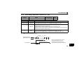
CONNECTION DIAGRAM AND TERMINAL
4.1
Connection Diagram
Relay contact signal input (sink logic *3)
Unit's place
Ten's place
Hundred's place
Thousand's place
*1
*2
*3
20
X0
X1
X2
X3
X4
X5
X6
X7
X8
X9
X10
X11
X12
X13
X14
X15
DY
SD *1
FR-A7AX
Open collector signal input (sink logic *3)
AY41 type transistor
output unit *2
Unit's place
Ten's place
Hundred's place
Thousand's place
Reading command
Inverter
1
2
3
4
5
6
7
8
9
10
11
12
13
14
15
16
17
18
19
35
36
X0
X1
X2
X3
X4
X5
X6
X7
X8
X9
X10
X11
X12
X13
X14
X15
*2
FR-A7AX
DY
PC *1
Inverter
Use terminal SD or PC on the inverter.
AY41 type unit requires 24VDC power.
Example of connection with the output module (AY41 type) of Mitsubishi programmable controller. Refer to the
output module manual for details of the output module.
The control logic is the same as that of the inverter.
When the logic of the inverter is changed, the option logic also changes. For details of changing the control logic,
refer to the inverter manual.
CONNECTION DIAGRAM AND TERMINAL
REMARKS
• As the input signals are at low level, use two parallel micro signal contacts or a twin contact for relay contact inputs
to prevent a contact fault.
Micro signal contacts
Twin contacts
• A transistor of the following specifications should be selected for the open collector signal:
Electrical characteristics of the transistor used
⋅ Ic ≥ 10mA
⋅ Leakage current: 100µA maximum
⋅ VCE ≥ 30V
⋅ If Ic ≥ 10mA, VCE (sat) voltage is 3V maximum
4
21
CONNECTION DIAGRAM AND TERMINAL
4.2
Internal Block Diagram
The following is the internal block diagram of the FR-A7AX.
X0
Connector
Controller
X15
DY
22
CONNECTION DIAGRAM AND TERMINAL
4.3
Terminals
Terminal Terminal
Location Symbol
z FR-A7AX
X10
X11
X12
X13
X14
X15
DY
Plug-in
option
X0
X1
X2
X3
X4
X5
X6
X7
X8
X9
Inverter
Description
Digital signal input terminal (frequency setting signal terminal)
Input the digital signal at the relay contact or open collector
terminal. (Refer to page 20.)
For the digital signal input, you can choose either the BCD code
X0 to X15 input or binary input.
BCD code input.... 3-digit (999 maximum) or 4-digit (9999
maximum)
Binary input .......... binary 12-bit (X0 to X11, FFFH maximum) or
binary 16-bit (X0 to X15, FFFFH maximum)
Data read timing input signal
Use when a digital signal read timing signal is necessary. When
Pr. 305 Read timing operation selection ="1", data is read only
DY
during the DY signal is on. In addition, the X0 to X15 data before
signal-off is retained by switching the DY signal off. (Refer to page
29.)
Common terminal (sink)
SD
Common terminal for digital and data read timing signals.
Use terminal SD of the inverter.
External transistor common terminal (sink), common terminal (source)
When connecting the transistor output (open collector output) of
a programmable controller, etc., connect the external power
PC
common (+) to this terminal to prevent a fault occurring due to
leakage current. When you have selected the source logic, this
terminal is used as a common terminal. Use terminal PC of the
inverter.
23
4
CONNECTION DIAGRAM AND TERMINAL
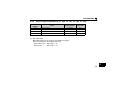
4.4
Code Input Example
The following explains examples of terminal status and input value at BCD code input and binary input.
Example: when the input value is 6325
BCD Code Input
Digit
1
10
100
1000
Terminal
name
Terminal input
status
X0
X1
X2
X3
X4
X5
X6
X7
X8
X9
X10
X11
X12
X13
X14
X15
ON
OFF
ON
OFF
OFF
ON
OFF
OFF
ON
ON
OFF
OFF
OFF
ON
ON
OFF
Example: when the input value is AB65H
Binary Input
Input
value
5
2
3
6
Terminal
name
Terminal input
status
X0
X1
X2
X3
X4
X5
X6
X7
X8
X9
X10
X11
X12
X13
X14
X15
ON
OFF
ON
OFF
OFF
ON
ON
OFF
ON
ON
OFF
ON
OFF
ON
OFF
ON
Input value
(hexadecimal)
Input
value
(decimal)
5
6
43877
B
A
CAUTION
• For the BCD code input, the input value of each digit is from 0 to 9. When the value greater than 9 is input, it
is made invalid and the last value is retained.
24
5
PARAMETERS
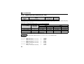
5.1
Parameter List
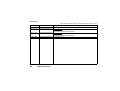
The following parameters are used for the plug-in option (FR-A7AX).
The FR-A7AX does not function with the factory setting. When a value other than "9999" is set in Pr. 304,
digital input is enabled.
Set the following parameters according to applications.
Parameter
Number
Name
Setting Range
Minimum
Setting
Increments
300 *1
BCD input bias
0 to 400Hz
0.01Hz
301 *1
BCD input gain
0 to 400Hz, 9999
0.01Hz
302 *1
BIN input bias
0 to 400Hz
0.01Hz
303 *1
BIN input gain
0 to 400Hz, 9999
0.01Hz
304 *1
305 *1
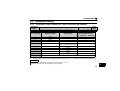
329 *1, 4
447 *5
448 *5
804 *5
Digital input and analog input
compensation enable/disable selection
Read timing operation selection
Digital input unit selection
Digital torque command bias
Digital torque command gain
Torque command source selection
Initial
Value
Refer to
page
0Hz
60Hz
(50Hz) *3
0Hz
60Hz
(50Hz) *3
31
31
31
31
0 to 4, 10 to 14,
9999 *2
0, 1, 10
0, 1, 2, 3
0 to 400%
1
9999
27, 28, 35
1
1
1%
0
1
0
0 to 400%, 9999
1%
150%
0, 1, 3 to 6
1
0
29
34
35
35
35
25
5
PARAMETERS
*1
*2
*3
*4
*5
Parameters which can be displayed when the plug-in option (FR-A7AX) is mounted.
The setting range of Pr. 304 differs according to the inverter used.
⋅FR-A700/F700 series ........................Refer to page 27
⋅FR-E700 series...................................Refer to page 28
The initial value of the EC version is 50Hz.
For Pr. 329, write is disabled during operation even when "2" is set in Pr. 77. When changing the parameter setting,
stop the operation. Also parameter clear is made invalid.
These parameters can be set for the FR-A700 series only.
REMARKS
• Binary input ............ The input data is taken in hexadecimal
BCD code input ...... The input data is taken in decimal
26
PARAMETERS
5.2
Parameter Setting
5.2.1
Selection of input method (Pr. 304) (FR-A700/F700 SERIES)
Parameter
Number
304
Name
Digital input and analog input compensation enable/disable selection
Pr. 304 Setting
BCD Code Input
Binary Input
Setting Range
Initial
Value
0 to 4,10 to 14, 9999
9999
Availability of Analog
Input Compensation *1
({: enabled, ×: disabled)
×
12-bit
×
{
12-bit
{
12-bit
4 *2
Torque command value input
10
4-digit
×
11
16-bit
×
12
4-digit
{
13
16-bit
{
16-bit
14 *2
Torque command value input
9999 (initial value)
No function
*1 Use terminal 1 for analog input compensation. Refer to the inverter instruction manual for details of terminal 1.
*2 These parameters can be set for the FR-A700 series only. Refer to page 35 for details of torque command value input.
0
1
2
3
3-digit
3-digit
REMARKS
• Signal X12 to X15 become invalid when 0 to 4 are set in Pr. 304.
• Refer to page 24 for BCD code/ binary input example.
27
5
PARAMETERS
5.2.2
Selection of input method (Pr. 304) (FR-E700 series)
Parameter
Number
304
Name
Digital input and analog input compensation enable/disable selection *
0, 1, 10, 11, 9999
9999
BCD Code Input
Binary Input
0
1
10
11
3-digit
4-digit
12-bit
16-bit
No function
For the FR-E700 series, analog input compensation can not be performed.
REMARKS
• Signal X12 to X15 become invalid when "0, 1" are set in Pr. 304.
• Refer to page 24 for BCD code/ binary input example.
28
Initial
Value
Pr. 304 Setting
9999 (initial value)
*
Setting Range
PARAMETERS
5.2.3
Read timing operation selection (Pr. 305)
Parameter
Number
305
Pr. 305 Setting
Name
Setting Range
Initial
Value
0, 1, 10
0
Read timing operation selection
Filter
0 (initial value)
Without
1
Without
10
With
Description
The set frequency data entered from the digital signal input terminals (X0 to X15) is
always imported independently of whether the DY signal is on or off.
The set frequency data entered from the digital signal input terminals (X0 to X15) is
imported only when the DY signal is on.
The set frequency data is not imported when the DY signal is off.
Therefore, even if the input status of the X0-X15 signal changes, the set frequency
data before off of the DY signal is valid.
The set frequency data entered from the digital signal input terminals (X0 to X15) is
always imported independently of whether the DY signal is on or off.
The time lag when digital signals change can be compensated with a filter.
(1) When "0 or 10" is set in Pr. 305
Filter (Pr. 305 = "10")
Digital signal input
(terminal X0 to X15)
20ms or more necessary*
Reflected on
the set frequency
Set frequency
* Hold the digital signal input (X0 to
X15) status for 20ms or more.
Changing the signal within 20ms
may not reflect it on the set frequency.
20ms maximum
29
5
PARAMETERS
(2) How to use the DY signal (when "1" is set in Pr. 305)
1ms or more
1ms or more
Digital signal input
(terminal X0 to X15)
Data read timing signal
(terminal DY)
OFF
ON
20ms or more
necessary
ON
REMARKS
• When Pr. 305 = "1", each terminal from X0 to X15 is all recognized as off when the inverter is turned on in terminal
DY off status.
For example, when bias is set to 20Hz, turning the power supply on in the DY signal off status and then turning on
the start signal will make the frequency command valid, starting the inverter to operate at 20Hz.
(3) SERIAL number check
The setting of "10" for Pr. 305 can be used for the FR-A700/E700 series and FR-F700 series produced in
June 2004 or later. Check the SERIAL number indicated on the inverter rating plate or package.
Refer to the inverter manual for the location of the rating plate.
X46XXXXXX
No.
Year produced
Control number
Month produced
The SERIAL is made up of 1 version symbol, 2 numeric characters or 1 alphabet
letter and 2 numeric characters indicating year and month, and 6 numeric
characters indicating control number.
Month is indicated as 1 to 9, X (October), Y (November), and Z (December).
30
PARAMETERS
5.2.4
Bias and gain adjustment (Pr. 300, Pr. 301, Pr. 302, Pr. 303)
Parameter
Number
300
301
302
303
Name
BCD input bias
BCD input gain
BIN input bias
BIN input gain
Setting Range
Initial Value
0 to 400Hz
0 to 400Hz, 9999
0 to 400Hz
0 to 400Hz, 9999
0Hz
60Hz (50Hz) *
0Hz
60Hz (50Hz) *
* The initial value of the EC version is 50Hz.
(1) Bias adjustment
Bias adjustments can be made for the digital input signal.
Set the set frequency at the digital input of 0.
⋅ BCD code input...... Set using Pr. 300.
⋅ Binary input ............ Set using Pr. 302.
31
5
PARAMETERS
(2) Gain adjustment
The gain may be set in either of the following two ways:
Output frequency(Hz)
How to set the output frequency when the digital input signal is "999 or 9999" (BCD code input),
and "FFFH or FFFFH" (binary input).
⋅ BCD code input .. Set using Pr. 301.
⋅ Binary input ........ Set using Pr. 303.
The output frequency is factory-set to 60Hz (EC version : 50Hz).
Pr. 301
Pr. 303
Gain
Pr. 300
Pr. 302
Bias
0
999(9999)
0
FFFH(FFFFH)
Digital input signal (BCD)
Pr.304 = "0, 2 (10, 12)" *
Digital input signal (Binary)
Pr.304 = "1, 3 (11, 13)" *
* For the FR-A700/F700 series only, "2, 3, 12, 13" can be set.
CAUTION
• The maximum output frequency for operation with the digital input signal is the "gain" value set in
Pr. 301 and Pr. 303.
To set the maximum output frequency at 60Hz (EC version : 50Hz) or more, change "gain" with the
operation panel.
32
PARAMETERS
Output frequency
(Hz)
How to set the BCD code or binary value as the output frequency setting
When "9999" is set in Pr. 301 (BCD code input) or Pr. 303 (binary input), the digital input value is set as the
output frequency.
(For example, to set the output frequency to 120Hz when the BCD code input is "120")
120
Digital input signal (BCD)
0
120
REMARKS
• When this setting method is used, "bias" setting (Pr. 300 or Pr. 302) cannot be made.
33
5
PARAMETERS
5.2.5
Digital input unit selection (Pr. 329)
Parameter
Number
329
Name
Setting Range
Initial Value
0, 1, 2, 3
1
Digital input unit selection *1
When "9999" is set in Pr. 301 or Pr. 303, the increments when the digital signal is set as output frequency
can be set. (Refer to page 33)
Frequency = digital input signal value × Pr. 329 input increments
Pr. 329 Setting
Input Value
Increments
Available Frequencies *
12-bit
BCD code
0
10
0 to 9990Hz
1 (factory setting)
1
0 to 999Hz
2
0.1
0 to 99.9Hz
3
0.01
0 to 9.99Hz
* These are not the inverter maximum output frequencies.
16-bit
Binary
BCD code
Binary
0 to 40950Hz
0 to 4095Hz
0 to 409.5Hz
0 to 40.95Hz
0 to 99990Hz
0 to 9999Hz
0 to 999.9Hz
0 to 99.99Hz
0 to 655350Hz
0 to 65535Hz
0 to 6553.5Hz
0 to 655.35Hz
REMARKS
• When the values other than "9999" are set in Pr. 301 or Pr. 303, Pr. 329 is made invalid.
<Example>
Pr. 329 = 0
Pr. 329 = 1
Pr. 329 = 2
Pr. 329 = 3
34
BCD code = 111
Binary = 100H (256 in decimal)
BCD code = 111
Binary = 100H (256 in decimal)
BCD code = 111
Binary = 100H (256 in decimal)
BCD code = 111
Binary = 100H (256 in decimal)
→
→
→
→
→
→
→
→
1110Hz
2560Hz
111Hz
256Hz
11.1Hz
25.6Hz
1.11Hz
2.56Hz
PARAMETERS
5.2.6
16-bit digital torque command (FR-A700 series only)
Parameter
Name
Digital input and analog input
compensation enable/disable selection
Digital torque command bias
Digital torque command gain
Torque command source selection
304
447
448
804
Setting Range
Initial Value
0 to 4, 10 to 14, 9999
9999
0 to 400%
0 to 400%, 9999
0, 1, 3 to 6
0
150%
0
Digital torque command can be given under torque control using the FR-A7AX.
A digital command using the FR-A7AX can be given when "4 (12-bit)" or "14 (16-bit)" is set in Pr. 304 and "4" is
set in Pr. 804 Torque command source selection.
Pr.804
parameter setting
0
1
3
4
5
6
Description
Torque command by terminal 1 analog input
Torque command by parameter setting
Setting value of Pr.805 or Pr.806 (-400% to 400%)
Remarks
Refer to the inverter manual for details.
Refer to the instruction manual of the
FR-A7NC for details.
12-bit digital input (FR-A7AX)
When "4" is set in Pr. 304
16-bit digital input (FR-A7AX)
When "14" is set in Pr. 304
Refer to the inverter manual for details.
Refer to the instruction manual of the
Torque command by CC-Link communication (FR-A7NC) FR-A7NC for details.
Torque command by CC-Link communication (FR-A7NC)
35
5
PARAMETERS
The input signal uses the last 15 (11) bits as torque command and the most significant bit as sign.
When 16-bit is selected
Bit15
sign bit
0: positive, 1: negative
Bit0
0 to 7FFFH or 0 to 190H (400)
REMARKS
• The digital torque command is input only by binary input.
36
PARAMETERS
z Input method of torque command
Torque command may be input in either of the following two ways:
(1) How to set the torque command value when the input signal is 0 and 7FFFH (7FFH)
Set the torque command value when the
Torque command value
input signal is "0" in Pr. 447 and the
Pr. 448 150%
torque command value when the input
Initial value
signal is "7FFFH (7FFH) in Pr. 448.
The figure on the right shows the case
7FFFH
when the torque command value is set
(7FFH)
Digital input signal
using input signal 7FFFH (7FFH) when
7FFFH
0
the torque command value is 150%
Pr. 447 (7FFH)
(initial value at Pr. 448). When the most
significant bit of input signal is positive, a
-150%
negative torque command value (-150%) Most significant bit = 1
Most significant bit = 0
is set also at the same time.
37
5
PARAMETERS
(2) How to set the digital input value as the torque command value
When "9999" is set in Pr. 448, the input signal is considered as a torque command value.
For example, the torque command value when the input signal is 190H (400) is 400% as shown below.
Even if a value higher than 190H (400) is input, the torque command value is clamped at 400%.
Torque command value
400%
7FFFH
(7FFH)
190H
(400)
0
Most significant bit = 1
38
-400%
190H
(400)
7FFFH Digital input signal
(7FFH)
Most significant bit = 0
PARAMETERS
5.3
Instructions
(1) Acceleration/deceleration time
When the frequency is set with the digital input signal, the acceleration/deceleration time is the period
of time required to reach the Acceleration/deceleration reference frequency set in Pr. 20. This is the same
as when using the analog signal input.
(2) There are the following restrictions on the digital input signal:
When the signal is used to enter a BCD code, 0AH to 0FH entries are ignored during operation and the
previous inputs are used to continue operation.
If binary input is changed to BCD code input with 0AH to 0FH input, the set frequency becomes 0Hz.
(3) If 0 to 5V (0 to 10V) is input at the inverter terminal 1 from the external potentiometer with the FR-A7AX
fitted in the FR-A700/F700 series, the inverter operates at the frequency obtained by adding the FRA7AX BCD code input and the compensation input from terminal 1 only when "2, 3, 12 or 13" is set in
Pr. 304.
When switching the inputs e.g. between volume input to perform manual operation and BCD code input
to perform automatic operation, set the BCD code input to "0" under manual operation.
(4) The priorities of the frequency setting are as follows.
JOG> Stop-on contact (RT, RL) > Multi-speed operation (RH, RM, RL) > PID (X14) > AU (terminal 4)
> Pulse train input > Digital command by the FR-A7AX > terminal 2*
* When digital input is valid, terminal 2 is invalid.
39
5
REVISIONS
*The manual number is given on the bottom left of the back cover.
Print Date
*Manual Number
Revision
Sep. 2005
IB(NA)-0600164ENG-A First edition
IB(NA)-0600164ENG-B Additions
Dec. 2007
IB(NA)-0600164ENG-C
Oct. 2009
Compatible with the FR-E700 series
IB(NA)-0600164ENG-D y Partial changes
May 2004
Compatible with the FR-A700 series
40
IB(NA)-0600164ENG-D
Additions