1
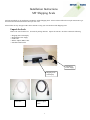
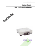
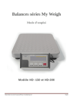
Scale Documentation
Mettler Toledo
USB PS Scale Installation
Table of Contents
Unpack the Scale..........................................................................................................................1
Place the scale on a level surface.................................................................................................2
Level the scale..............................................................................................................................2
Place platter on scale....................................................................................................................3
Plug the Scale in...........................................................................................................................3
Scale to Communications Port connections.................................................................................3
USB ..............................................................................................................................................4
RS232...........................................................................................................................................4
Verify power-up sequence when GEOCAL™ is enabled .............................................................4
Instructions for UPS Worldship Customers.................................................................................6
Troubleshooting ...........................................................................................................................7
Technical Support ........................................................................................................................8
Warranty Returns .........................................................................................................................8
Replacement Components............................................................................................................8
Installation Instructions
MT Shipping Scale
Welcome and thank you for purchasing your Mettler-Toledo Shipping Scale. Please read and follow these simple instructions to get
the maximum benefit and satisfaction from your new scale.
Please follow the easy setup procedures in this manual to setup your new Mettler-Toledo Shipping Scale.
Unpack the Scale
Remove the scale from the box. Set aside all packing materials. Inspect the contents. Each box contains the following.
•
•
•
•
•
Shipping Scale with Display
Wall Mount Power Supply
USB Cable
RS232 Adapter (DB9) Cable
Installation Instructions
Wall Mount
Power Supply
Shipping Scale
with Display
USB Cable
RS232 Adapter
Cable
1
Place the scale on a level surface.
Place the scale near a power outlet. Ensure the scale is not touching objects that may affect the weight reading.
Level the scale.
Level the scale by turning the scale feet until the leveling bubble is centered and the scale does not wobble. The leveling
bubble is located underneath the platter. See photo.
Leveling
Feet 4 per
Leveling
bubble
2
Incorrect
Correct
Bubble is not
Within circle
Bubble is
Within circle
Place platter on scale.
Gently place the platter on the scale. If your scale comes with a stainless steel (metal) platter, you may wish to remove the
plastic protective skin.
Plastic Platter
shown
Plug the Scale in.
Tilt the scale on its side and plug the power connector into the bottom of the scale. Plug the power supply or power cord into
a power outlet. Note: If using the USB connection, it is not necessary to plug the scale into a power outlet. The scale will be
powered through the USB connection.
Power cord
Power cord plug
location
RS232 Connector
(Adapter Cable Included)
USB Connector
Bottom view of scale
Scale to PC Communications Port connections
If you are using a PC-Based manifest shipping systems, plug the scale into an open communications port on your computer.
The ports should be labeled USB, COM1, or COM2. Use the supplied USB or RS232 adapter cable to make the connection.
This picture depicts the COM ports on a typical PC.
U SB
CO M 1
CO M 2
3
USB
USB scale connection is very automatic. When you connect the scale to your PC’s USB port, the PC will
automatically sense the scale. Different versions of Microsoft’s operating systems will vary the set-up slightly.
*** When using USB the power adapter is not necessary. The scale will be powered through the USB cable.***
Windows 98: The set-up for the USB drivers for Windows 98 is fairly automatic but requires some interaction with
dialog boxes to complete.
1.
A dialog box stating “New Hardware Found” will appear. Immediately, the PC will begin to “Build Driver
Information Database”.
Once this is complete, a “Add New Hardware” Wizard will appear. Select the bottom choice of “Display a list
of all the drivers in a specific location, so you can select the driver you want”.
The “USB Human Interface Device” will appear as the default driver.
Click on “OK” and then “Finish”
2.
3.
4.
Windows 2000 / XP: This is more automatic. There are no choices to make. The PC will automatically recognize
the scale and install the appropriate driver. With no human interaction required
RS232
NOTE: Make sure the power to your computer is switch off before you change ports. If you have plugged your
scale into the incorrect port, you must reboot your computer after changing ports.
NOTE: DO NOT substitute your RS232 serial cable with an ordinary RS232 cable. If you require a longer cable
for your application, call our MT Express technical support at 1-800-786-0812 to purchase an additional cable.
Verify power-up sequence when GEOCAL™ is enabled.
When you first plug in the scale, the display shows a brief power-up sequence. This sequence only appears ONCE, so please
make sure you do it carefully. Once it is done, it displays a prompt for the GEOCAL™ location code.
>0<
lb
kg
>0<
The GEOCAL ™ feature allows the scale calibration to be adjusted for gravitational variations in your area.
Refer to the table and chart to determine the geographical two-digit code for your location. Scroll through the list by pressing
>0<
the
key. Stop at your code and press the
key twice. The word done will be displayed briefly and the scale will
restart itself.
4
GEOCAL™ Location Codes
State
Alabama
Birmingham & North
South of Birmingham
Alaska
Arizona
Phoenix & North
South of Phoenix
Arkansas
California
Colorado
Denver & North
South of Denver
Connecticut
Delaware
Florida
West Palm Beach &
North
South of West Palm
Beach
Georgia
Hawaii
Idaho
North of Salmon River
Mtns
South of Salmon River
Mtns
Illinois
Bloomington & North
South of Bloomington
Indiana
North of Indianapolis
Indianapolis & South
Iowa
North of Des Moines
Code
State
Kansas
Kentucky
Louisiana
Maine
Code
14
14
12
18
State
North Dakota
Ohio
Akron & North
South of Akron
15
17
Oklahoma
Oregon
Salem & North
Between Oakridge
& Salem
South of Oakridge
11
Maryland
Massachusetts
Michigan
Northwest of Lake
Michigan
Southeast of Lake
Michigan
Minnesota
Mississippi
Kosciusko & North
South of Kosciusko
Missouri
North of Springfield
Springfield & South
10
Montana
12
9
17
Helena & North
South of Helena
Nebraska
Nevada
16
13
12
See
map
12
11
13
See
map
13
12
16
15
16
15
16
15
17
18
17
Code
18
16
15
13
18
17
16
16
16
13
17
13
18
17
15
13
Pennsylvania
Rhode Island
South Carolina
South Dakota
Tennessee
Texas
Northeast of
Colorado River
Southwest of
Colorado River
Utah
Vermont
Virginia
Washington, DC
New Hampshire
17
Washington State
18
New Jersey
New Mexico
New York
Albany & North
South of Albany
North Carolina
Raleigh & North
South of Raleigh
16
11
West Virginia
Wisconsin
Green Bay & North
South of Green Bay
Wyoming
North of Casper
Casper & South
15
18
13
12
15
14
17
16
14
13
Des Moines & South 16
5
12
11
13
17
14
15
18
17
15
14
6
Troubleshooting
1) I don’t see a weight on the scale display.
The scale may not be plugged into a wall outlet. The scale needs power and must be plugged into a wall outlet. The
scale comes with a wall mount power supply. One end plugs into a wall outlet. The other end plugs into the scale
circuit board. The power receptacle on the scale can be found underneath the scale next to the display and serial
connector. Once the scale is powered, it steps through its normal start-up sequence and will soon show the weight
display. Make sure there is nothing on the scale or touching the top when it first powers-up. If you have verified
that the outlet is fine, the scale is plugged in, and you still have nothing on the display, then contact our MT Express
technical support department 1-800-786-0812.
2) The scale is showing funny brackets on the display.
This generally means that the scale was originally powered up with some weight (maybe a package) on it. Simply
un-plug the scale from the wall, make sure there is no weight on the scale or that the scale is touching anything, and
plug the scale back in. The scale will go through its usual start-up sequence, and the problem should be solved.
7
Technical Support
For technical support, contact our MT Express technical support department at 1-800-786-0812.
Warranty Returns
If you have an out of box failure or should have to return your scale for any reason, contact us at www.mt.upsscales.com . If
you prefer, you may contact us by calling our MT Express technical support department at 1-800-786-0812.
Replacement Components
For purchasing replacement components please log onto our website located at at www.mt.upsscales.com. You can call our
MT Express technical support department at 1-800-786-0812 for ordering replacements.
Replacement Components
Mettler Toledo Part Number
Base Mount Display
02701000000
Wall Mount Display with “Y” cable
02705100000
Dual Wall Mount Display
02704100000
9’ RS232 Cable
09000322000
Power Supply – UPS Only
*14862000A
Power Supply – Wall Mount
*13515600A
ABS Plastic Platter for PS60/PS30
*14819500D
Ball Top Platter for PS60 Only
09060161000
Stainless Steel Platter for PS60
*15083400A
* Indicates the part number may have a revision level.
8
METTLER TOLEDO
1900 Polaris Parkway
Columbus, Ohio 43240-2020
METTLER TOLEDO®is a registered trademark of Mettler-Toledo, Inc.
©2003 Mettler-Toledo, Inc.
Printed in USA