1
Empowered by Innovation
Software Program Manual
P/N 0913202
Rev 3, May 2008
Printed in U.S.A.
1.0
Technical Support Web Site:
http://www.necux5000.com
This manual has been developed by NEC Unified Solutions, Inc. It is intended for the use of its customers and
service personnel, and should be read in its entirety before attempting to install or program the system. Any
comments or suggestions for improving this manual would be appreciated. Forward your remarks to:
NEC Unified Solutions, Inc.
4 Forest Parkway
Shelton, CT 06484
necunifiedsolutions.com
Nothing contained in this manual shall be deemed to be, and this manual does not constitute, a warranty of, or
representation with respect to, any of the equipment covered. This manual is subject to change without notice and
NEC Unified Solutions, Inc. has no obligation to provide any updates or corrections to this manual. Further, NEC
Unified Solutions, Inc. also reserves the right, without prior notice, to make changes in equipment design or
components as it deems appropriate. No representation is made that this manual is complete or accurate in all
respects and NEC Unified Solutions, Inc. shall not be liable for any errors or omissions. In no event shall NEC Unified
Solutions, Inc. be liable for any incidental or consequential damages in connection with the use of this manual. This
document contains proprietary information that is protected by copyright. All rights are reserved. No part of this
document may be photocopied or reproduced without prior written consent of NEC Unified Solutions, Inc.
©2008 by NEC Unified Solutions, Inc. All Rights Reserved.
Printed in U.S.A.
Table of Contents
Introduction to Programming . . . . . . . . . . . . . . . . . . . . . . . . . . . . . . . . . . . . . . . . . . . 1
Before You Start Programming . . . . . . . . . . . . . . . . . . . . . . . . . . . . . . . . . . . . . . . 1
Program 10 : System Configuration Setup . . . . . . . . . . . . . . . . . . . . . . . . . . . . . . . 13
10-01 : Time and Date . . . . . . . . . . . . . . . . . . . . . . . . . . . . . . . . . . . . . . . . . . . . . 13
10-02 : Location Setup . . . . . . . . . . . . . . . . . . . . . . . . . . . . . . . . . . . . . . . . . . . . . 15
10-03 : Blade Setup . . . . . . . . . . . . . . . . . . . . . . . . . . . . . . . . . . . . . . . . . . . . . . . 17
10-04 : Music on Hold Setup . . . . . . . . . . . . . . . . . . . . . . . . . . . . . . . . . . . . . . . . 29
10-05 : General Purpose Relay Setup . . . . . . . . . . . . . . . . . . . . . . . . . . . . . . . . . 31
10-06 : ISDN BRI Setup . . . . . . . . . . . . . . . . . . . . . . . . . . . . . . . . . . . . . . . . . . . 33
10-07 : Conversation Record Circuits . . . . . . . . . . . . . . . . . . . . . . . . . . . . . . . . . 35
10-08 : Pre-Ringing Setup . . . . . . . . . . . . . . . . . . . . . . . . . . . . . . . . . . . . . . . . . . 37
10-09 : DTMF and Dial Tone Circuit Setup . . . . . . . . . . . . . . . . . . . . . . . . . . . . 38
10-12 : CCPU Network Setup . . . . . . . . . . . . . . . . . . . . . . . . . . . . . . . . . . . . . . . 40
10-13 : In-DHCP Server Setup . . . . . . . . . . . . . . . . . . . . . . . . . . . . . . . . . . . . . . 43
10-14 : Managed Network Setup . . . . . . . . . . . . . . . . . . . . . . . . . . . . . . . . . . . . . 45
10-15 : Client Information Setup . . . . . . . . . . . . . . . . . . . . . . . . . . . . . . . . . . . . . 47
10-16 : Option Information Setup . . . . . . . . . . . . . . . . . . . . . . . . . . . . . . . . . . . . 49
10-17 : H.323 Gatekeeper Setup . . . . . . . . . . . . . . . . . . . . . . . . . . . . . . . . . . . . . 53
10-18 : H.323 Alias Address Setup . . . . . . . . . . . . . . . . . . . . . . . . . . . . . . . . . . . 55
10-19 : VOIPDB DSP Resource Selection . . . . . . . . . . . . . . . . . . . . . . . . . . . . . 57
10-20 : LAN Setup for External Equipment . . . . . . . . . . . . . . . . . . . . . . . . . . . . 59
10-21 : CCPU Hardware Setup . . . . . . . . . . . . . . . . . . . . . . . . . . . . . . . . . . . . . . 61
10-22 : Setting the Wake On LAN for APSU . . . . . . . . . . . . . . . . . . . . . . . . . . . 63
10-23 : H.323 System Interconnection . . . . . . . . . . . . . . . . . . . . . . . . . . . . . . . . 65
10-24 : Daylight Savings Setup . . . . . . . . . . . . . . . . . . . . . . . . . . . . . . . . . . . . . . 67
10-25 : H.323 Gateway Prefix Setup . . . . . . . . . . . . . . . . . . . . . . . . . . . . . . . . . . 69
10-26 : IP System Operation Setup . . . . . . . . . . . . . . . . . . . . . . . . . . . . . . . . . . . 71
10-27 : IP System ID . . . . . . . . . . . . . . . . . . . . . . . . . . . . . . . . . . . . . . . . . . . . . . 73
10-28 : SIP Trunk Basic Setup . . . . . . . . . . . . . . . . . . . . . . . . . . . . . . . . . . . . . . . 75
10-29 : SIP Proxy Setup . . . . . . . . . . . . . . . . . . . . . . . . . . . . . . . . . . . . . . . . . . . . 77
10-30 : SIP Authentication Information . . . . . . . . . . . . . . . . . . . . . . . . . . . . . . . 80
10-31 : Networking Keep Alive Setup . . . . . . . . . . . . . . . . . . . . . . . . . . . . . . . . . 82
10-32 : PRI Networking Channel Limitation . . . . . . . . . . . . . . . . . . . . . . . . . . . . 84
10-33 : SIP Registrar/Proxy Setup . . . . . . . . . . . . . . . . . . . . . . . . . . . . . . . . . . . . 86
10-36 : SIP Trunk Registration Information Setup . . . . . . . . . . . . . . . . . . . . . . . 88
10-37 : UPnP Setup . . . . . . . . . . . . . . . . . . . . . . . . . . . . . . . . . . . . . . . . . . . . . . . 90
10-39 : T1/PRI Fractional Setup . . . . . . . . . . . . . . . . . . . . . . . . . . . . . . . . . . . . . 92
10-40 : IP Trunk Availability . . . . . . . . . . . . . . . . . . . . . . . . . . . . . . . . . . . . . . . . 93
10-41 : General Purpose Contact Detector Setup . . . . . . . . . . . . . . . . . . . . . . . . 95
10-42 : Virtual Loop Back Port Setting . . . . . . . . . . . . . . . . . . . . . . . . . . . . . . . . 97
10-45 : IP Routing Table Setup . . . . . . . . . . . . . . . . . . . . . . . . . . . . . . . . . . . . . . 99
UX5000 Software Program Manual
◆ Table of Contents- 1
Table of Contents
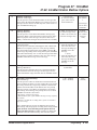
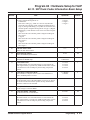
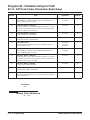
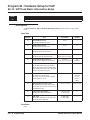
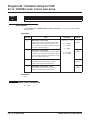
10-46 : DT700 Server Information Setup . . . . . . . . . . . . . . . . . . . . . . . . . . . . . 101
10-47 : Terminal License Server Information Setup . . . . . . . . . . . . . . . . . . . . . 104
10-48 : License Activation . . . . . . . . . . . . . . . . . . . . . . . . . . . . . . . . . . . . . . . . . 105
10-49 : License File Activation . . . . . . . . . . . . . . . . . . . . . . . . . . . . . . . . . . . . . 106
10-50 : License Information . . . . . . . . . . . . . . . . . . . . . . . . . . . . . . . . . . . . . . . . 107
10-51 : PRI/T1 Selection for 1PRIU Blade . . . . . . . . . . . . . . . . . . . . . . . . . . . . 109
10-52 : Free/Demo License Information . . . . . . . . . . . . . . . . . . . . . . . . . . . . . . 111
10-54 : License Configuration for Blades . . . . . . . . . . . . . . . . . . . . . . . . . . . . . 112
10-55 : UX5000 Blade Network Setup . . . . . . . . . . . . . . . . . . . . . . . . . . . . . . . 114
10-56 : XML Portal Page for IP Terminal . . . . . . . . . . . . . . . . . . . . . . . . . . . . . 116
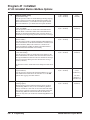
Program 11 : System Numbering . . . . . . . . . . . . . . . . . . . . . . . . . . . . . . . . . . . . . . 119
11-01 : System Numbering . . . . . . . . . . . . . . . . . . . . . . . . . . . . . . . . . . . . . . . . 119
11-02 : Extension Numbering . . . . . . . . . . . . . . . . . . . . . . . . . . . . . . . . . . . . . . 129
11-04 : Virtual Extension Numbering . . . . . . . . . . . . . . . . . . . . . . . . . . . . . . . . 131
11-06 : ACI Extension Numbering . . . . . . . . . . . . . . . . . . . . . . . . . . . . . . . . . . 133
11-07 : Department Group Pilot Numbers . . . . . . . . . . . . . . . . . . . . . . . . . . . . . 135
11-08 : ACI Group Pilot Number . . . . . . . . . . . . . . . . . . . . . . . . . . . . . . . . . . . 137
11-09 : Trunk Access Code . . . . . . . . . . . . . . . . . . . . . . . . . . . . . . . . . . . . . . . . 139
11-10 : Service Code Setup (for System Administrator) . . . . . . . . . . . . . . . . . . 141
11-11 : Service Code Setup (for Setup/Entry Operation) . . . . . . . . . . . . . . . . . 144
11-12 : Service Code Setup (for Service Access) . . . . . . . . . . . . . . . . . . . . . . . 148
11-13 : Service Code Setup (for ACD) . . . . . . . . . . . . . . . . . . . . . . . . . . . . . . . 152
11-14 : Service Code Setup (for Hotel) . . . . . . . . . . . . . . . . . . . . . . . . . . . . . . . 154
11-15 : Service Code Setup, Administrative (for Special Access) . . . . . . . . . . 156
11-16 : Single Digit Service Code Setup . . . . . . . . . . . . . . . . . . . . . . . . . . . . . . 158
11-17 : ACD Group Pilot Number . . . . . . . . . . . . . . . . . . . . . . . . . . . . . . . . . . . 160
11-19 : Remote Conference Pilot Number Setup . . . . . . . . . . . . . . . . . . . . . . . 162
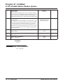
Program 12 : Night Mode Setup . . . . . . . . . . . . . . . . . . . . . . . . . . . . . . . . . . . . . . 165
12-01 : Night Mode Function Setup . . . . . . . . . . . . . . . . . . . . . . . . . . . . . . . . . 165
12-02 : Automatic Night Service Patterns . . . . . . . . . . . . . . . . . . . . . . . . . . . . . 167
12-03 : Weekly Night Service Switching . . . . . . . . . . . . . . . . . . . . . . . . . . . . . 170
12-04 : Holiday Night Service Switching . . . . . . . . . . . . . . . . . . . . . . . . . . . . . 172
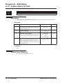
12-05 : Night Mode Group Assignment for Extensions . . . . . . . . . . . . . . . . . . 174
12-06 : Night Mode Group Assignment for Trunks . . . . . . . . . . . . . . . . . . . . . 175
12-07 : Text Data for Night Mode . . . . . . . . . . . . . . . . . . . . . . . . . . . . . . . . . . . 176
12-08 : Night Mode Service Range . . . . . . . . . . . . . . . . . . . . . . . . . . . . . . . . . . 178
Table of Contents - 2 ◆
UX5000 Software Program Manual
Table of Contents
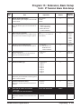
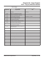
Program 13 : Abbreviated Dialing . . . . . . . . . . . . . . . . . . . . . . . . . . . . . . . . . . . . . 181
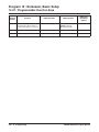
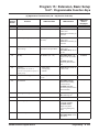
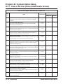
13-01 : Abbreviated Dialing Function Setup . . . . . . . . . . . . . . . . . . . . . . . . . . . 181
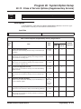
13-02 : Group Abbreviated Dialing Bins . . . . . . . . . . . . . . . . . . . . . . . . . . . . . . 183
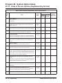
13-03 : Abbreviated Dialing Group Assignment for Extensions . . . . . . . . . . . . 185
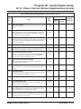
13-04 : Abbreviated Dialing Number and Name . . . . . . . . . . . . . . . . . . . . . . . . 187
13-05 : Abbreviated Dialing Trunk Group . . . . . . . . . . . . . . . . . . . . . . . . . . . . 189
13-07 : Telephone Book Number and Name . . . . . . . . . . . . . . . . . . . . . . . . . . . 191
13-08 : Telephone Book System Name . . . . . . . . . . . . . . . . . . . . . . . . . . . . . . . 193
13-09 : Telephone Book Group Name . . . . . . . . . . . . . . . . . . . . . . . . . . . . . . . . 195
13-10 : Telephone Book Routing . . . . . . . . . . . . . . . . . . . . . . . . . . . . . . . . . . . . 197
Program 14 : Trunk, Basic Setup . . . . . . . . . . . . . . . . . . . . . . . . . . . . . . . . . . . . . . 199
14-01 : Basic Trunk Data Setup . . . . . . . . . . . . . . . . . . . . . . . . . . . . . . . . . . . . . 199
14-02 : Analog Trunk Data Setup . . . . . . . . . . . . . . . . . . . . . . . . . . . . . . . . . . . 204
14-04 : Behind PBX Setup . . . . . . . . . . . . . . . . . . . . . . . . . . . . . . . . . . . . . . . . . 208
14-05 : Trunk Group . . . . . . . . . . . . . . . . . . . . . . . . . . . . . . . . . . . . . . . . . . . . . 210
14-06 : Trunk Group Routing . . . . . . . . . . . . . . . . . . . . . . . . . . . . . . . . . . . . . . 212
14-07 : Trunk Access Map Setup . . . . . . . . . . . . . . . . . . . . . . . . . . . . . . . . . . . . 214
14-08 : Music on Hold Source for Trunks . . . . . . . . . . . . . . . . . . . . . . . . . . . . . 216
14-09 : ACI Conversation Recording Destination for Trunks . . . . . . . . . . . . . . 218
14-10 : Power Failure Terminal for Trunks . . . . . . . . . . . . . . . . . . . . . . . . . . . . 220
14-11 : ID Setup for IP Trunk . . . . . . . . . . . . . . . . . . . . . . . . . . . . . . . . . . . . . . 221
4-12 : SIP Register ID Setup for IP Trunk . . . . . . . . . . . . . . . . . . . . . . . . . . . . . 223
Program 15 : Extension, Basic Setup . . . . . . . . . . . . . . . . . . . . . . . . . . . . . . . . . . 225
15-01 : Basic Extension Data Setup . . . . . . . . . . . . . . . . . . . . . . . . . . . . . . . . . 225
15-02 : Multi-Line Terminal Basic Setup . . . . . . . . . . . . . . . . . . . . . . . . . . . . . 228
15-03 : Single Line Terminal Basic Data Setup . . . . . . . . . . . . . . . . . . . . . . . . 237
15-05 : IP Terminal Basic Data Setup . . . . . . . . . . . . . . . . . . . . . . . . . . . . . . . . 241
15-06 : Trunk Access Map for Extensions . . . . . . . . . . . . . . . . . . . . . . . . . . . . 245
15-07 : Programmable Function Keys . . . . . . . . . . . . . . . . . . . . . . . . . . . . . . . . 247
15-08 : Incoming Virtual Extension Ring Tone Setup . . . . . . . . . . . . . . . . . . . 257
15-09 : Virtual Extension Ring Assignment . . . . . . . . . . . . . . . . . . . . . . . . . . . 259
15-10 : Incoming Virtual Extension Ring Tone Order Setup . . . . . . . . . . . . . . 261
15-11 : Virtual Extension Delayed Ring Assignment . . . . . . . . . . . . . . . . . . . . 263
15-12 : Conversation Recording Destination for Extensions . . . . . . . . . . . . . . 265
15-13 : Loop Keys . . . . . . . . . . . . . . . . . . . . . . . . . . . . . . . . . . . . . . . . . . . . . . . 267
15-14 : Programmable One-Touch Keys . . . . . . . . . . . . . . . . . . . . . . . . . . . . . . 269
15-16 : SIP Register ID Setup for Extension . . . . . . . . . . . . . . . . . . . . . . . . . . . 271
15-18 : Virtual Extension Key Enhanced Options . . . . . . . . . . . . . . . . . . . . . . . 273
15-19 : System Telephone Book Setup for Extension . . . . . . . . . . . . . . . . . . . . 275
15-20 : LCD Line Key Name Assignment . . . . . . . . . . . . . . . . . . . . . . . . . . . . 277
15-22 : Mobile Extension Setup . . . . . . . . . . . . . . . . . . . . . . . . . . . . . . . . . . . . 279
UX5000 Software Program Manual
◆ Table of Contents- 3
Table of Contents
Program 16 : Department Group Setup . . . . . . . . . . . . . . . . . . . . . . . . . . . . . . . . . 281
16-01 : Department Group Basic Data Setup . . . . . . . . . . . . . . . . . . . . . . . . . . 281
16-02 : Department Group Assignment for Extensions . . . . . . . . . . . . . . . . . . . 284
16-03 : Secondary Department Group . . . . . . . . . . . . . . . . . . . . . . . . . . . . . . . . 286
16-04 : Call Restriction Between Department Groups . . . . . . . . . . . . . . . . . . . 288
Program 20 : System Option Setup . . . . . . . . . . . . . . . . . . . . . . . . . . . . . . . . . . . . 291
20-01 : System Options . . . . . . . . . . . . . . . . . . . . . . . . . . . . . . . . . . . . . . . . . . . 291
20-02 : System Options for Multi-Line Terminals . . . . . . . . . . . . . . . . . . . . . . 293
20-03 : System Options for Single Line Terminals . . . . . . . . . . . . . . . . . . . . . . 297
20-04 : System Options for Virtual Extensions . . . . . . . . . . . . . . . . . . . . . . . . . 300
20-05 : Charging Cost Service . . . . . . . . . . . . . . . . . . . . . . . . . . . . . . . . . . . . . . 302
20-06 : Class of Service for Extensions . . . . . . . . . . . . . . . . . . . . . . . . . . . . . . . 303
20-07 : Class of Service Options (Administrator Level) . . . . . . . . . . . . . . . . . . 305
20-08 : Class of Service Options (Outgoing Call Service) . . . . . . . . . . . . . . . . 308
20-09 : Class of Service Options (Incoming Call Service) . . . . . . . . . . . . . . . . 311
20-10 : Class of Service Options (Answer Service) . . . . . . . . . . . . . . . . . . . . . 313
20-11 : Class of Service Options (Hold/Transfer Service) . . . . . . . . . . . . . . . . 315
20-12 : Class of Service Options (Charging Cost Service) . . . . . . . . . . . . . . . . 318
20-13 : Class of Service Options (Supplementary Service) . . . . . . . . . . . . . . . . 319
20-14 : Class of Service Options for DISA/E&M . . . . . . . . . . . . . . . . . . . . . . . 324
20-15 : Ring Cycle Setup . . . . . . . . . . . . . . . . . . . . . . . . . . . . . . . . . . . . . . . . . . 327
20-16 : Selectable Display Messages . . . . . . . . . . . . . . . . . . . . . . . . . . . . . . . . . 329
20-17 : Operator’s Extension . . . . . . . . . . . . . . . . . . . . . . . . . . . . . . . . . . . . . . . 332
20-18 : Service Tone Timers . . . . . . . . . . . . . . . . . . . . . . . . . . . . . . . . . . . . . . . 334
20-19 : System Options for Caller ID . . . . . . . . . . . . . . . . . . . . . . . . . . . . . . . . 336
20-20 : Message Setup for Non-Caller ID Data . . . . . . . . . . . . . . . . . . . . . . . . . 338
20-21 : System Options for Long Conversation . . . . . . . . . . . . . . . . . . . . . . . . 339
20-22 : System Options for IP DECT Service . . . . . . . . . . . . . . . . . . . . . . . . . . 341
20-23 : System Options for CTI . . . . . . . . . . . . . . . . . . . . . . . . . . . . . . . . . . . . . 343
20-25 : ISDN Options . . . . . . . . . . . . . . . . . . . . . . . . . . . . . . . . . . . . . . . . . . . . 345
20-28 : System Option for Trunk to Trunk Conversations . . . . . . . . . . . . . . . . 347
20-29 : Timer Class for Extensions . . . . . . . . . . . . . . . . . . . . . . . . . . . . . . . . . . 349
20-30 : Timer Class for Trunks . . . . . . . . . . . . . . . . . . . . . . . . . . . . . . . . . . . . . 351
20-31 : Timer Data . . . . . . . . . . . . . . . . . . . . . . . . . . . . . . . . . . . . . . . . . . . . . . . 353
20-34 : Remote Conference Group Setup . . . . . . . . . . . . . . . . . . . . . . . . . . . . . 357
Program 21 : Outgoing Call Setup . . . . . . . . . . . . . . . . . . . . . . . . . . . . . . . . . . . . . 359
21-01 : System Options for Outgoing Calls . . . . . . . . . . . . . . . . . . . . . . . . . . . . 359
21-02 : Trunk Group Routing for Extensions . . . . . . . . . . . . . . . . . . . . . . . . . . 362
21-03 : Trunk Group Routing for Trunks . . . . . . . . . . . . . . . . . . . . . . . . . . . . . 364
21-04 : Toll Restriction Class for Extensions . . . . . . . . . . . . . . . . . . . . . . . . . . 366
21-05 : Toll Restriction Class . . . . . . . . . . . . . . . . . . . . . . . . . . . . . . . . . . . . . . 368
Table of Contents - 4 ◆
UX5000 Software Program Manual
Table of Contents
21-06 : Toll Restriction Table Data Setup . . . . . . . . . . . . . . . . . . . . . . . . . . . . . 371
21-07 : Toll Restriction Override Password Setup . . . . . . . . . . . . . . . . . . . . . . 374
21-08 : Repeat Dial Setup . . . . . . . . . . . . . . . . . . . . . . . . . . . . . . . . . . . . . . . . . 376
21-09 : Dial Block Setup . . . . . . . . . . . . . . . . . . . . . . . . . . . . . . . . . . . . . . . . . . 378
21-10 : Dial Block Restriction Class Per Extensions . . . . . . . . . . . . . . . . . . . . . 380
21-11 : Extension Ringdown (Hotline) Assignment . . . . . . . . . . . . . . . . . . . . . 382
21-12 : ISDN Calling Party Number Setup for Trunks . . . . . . . . . . . . . . . . . . . 384
21-13 : ISDN Calling Party Number Setup for Extensions . . . . . . . . . . . . . . . . 386
21-14 : Walking Toll Restriction Password Setup . . . . . . . . . . . . . . . . . . . . . . . 388
21-15 : Individual Trunk Group Routing for Extensions . . . . . . . . . . . . . . . . . . 390
21-16 : Trunk Group Routing for Networks . . . . . . . . . . . . . . . . . . . . . . . . . . . 392
21-17 : IP (H.323/SIP) Trunk Calling Party Number Setup for Trunks . . . . . . 394
21-18 : IP (H.323) Trunk Calling Party Number Setup for Extensions . . . . . . . 396
21-19 : IP (SIP) Trunk Calling Party Number Setup for Extensions . . . . . . . . . 398
21-21 : Toll Restriction Class for Trunks . . . . . . . . . . . . . . . . . . . . . . . . . . . . . 400
Program 22 : Incoming Call Setup . . . . . . . . . . . . . . . . . . . . . . . . . . . . . . . . . . . . . 403
22-01 : System Options for Incoming Calls . . . . . . . . . . . . . . . . . . . . . . . . . . . 403
22-02 : Incoming Call Trunk Setup . . . . . . . . . . . . . . . . . . . . . . . . . . . . . . . . . 405
22-03 : Trunk Ring Tone Range . . . . . . . . . . . . . . . . . . . . . . . . . . . . . . . . . . . . 407
22-04 : Incoming Extension Ring Group Assignment . . . . . . . . . . . . . . . . . . . . 409
22-05 : Incoming Trunk Ring Group Assignment . . . . . . . . . . . . . . . . . . . . . . . 411
22-06 : Normal Incoming Ring Mode . . . . . . . . . . . . . . . . . . . . . . . . . . . . . . . . 413
22-07 : DIL Assignment . . . . . . . . . . . . . . . . . . . . . . . . . . . . . . . . . . . . . . . . . . 415
22-08 : DIL/IRG No Answer Destination . . . . . . . . . . . . . . . . . . . . . . . . . . . . . 417
22-09 : DID Basic Data Setup . . . . . . . . . . . . . . . . . . . . . . . . . . . . . . . . . . . . . . 419
22-10 : DID Translation Table Setup . . . . . . . . . . . . . . . . . . . . . . . . . . . . . . . . . 421
22-11 : DID Translation Number Conversion . . . . . . . . . . . . . . . . . . . . . . . . . . 423
22-12 : DID Intercept Ring Group . . . . . . . . . . . . . . . . . . . . . . . . . . . . . . . . . . . 426
22-13 : DID Trunk Group to Translation Table Assignment . . . . . . . . . . . . . . 428
22-14 : VRS Delayed Message for IRG . . . . . . . . . . . . . . . . . . . . . . . . . . . . . . 430
22-15 : VRS Waiting Message for Department Group . . . . . . . . . . . . . . . . . . . 432
22-16 : Private Call Refuse Target Area Setup . . . . . . . . . . . . . . . . . . . . . . . . . 434
22-17 : DID Conversion Table Area Setup for Time Pattern Mode . . . . . . . . . 436
22-18 : Private Call Assignment . . . . . . . . . . . . . . . . . . . . . . . . . . . . . . . . . . . . 438
22-20 : Flexible Ringing by Caller ID Per Time Pattern . . . . . . . . . . . . . . . . . . 440
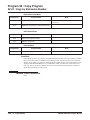
Program 23 : Answer Features Setup . . . . . . . . . . . . . . . . . . . . . . . . . . . . . . . . . . 443
23-02 : Call Pickup Groups . . . . . . . . . . . . . . . . . . . . . . . . . . . . . . . . . . . . . . . . 443
23-03 : Universal Answer/Auto Answer . . . . . . . . . . . . . . . . . . . . . . . . . . . . . . 445
23-04 : Ringing Line Preference for Virtual Extensions . . . . . . . . . . . . . . . . . . 447
UX5000 Software Program Manual
◆ Table of Contents- 5
Table of Contents
Program 24 : Hold/Transfer Setup . . . . . . . . . . . . . . . . . . . . . . . . . . . . . . . . . . . . . 449
24-01 : System Options for Hold . . . . . . . . . . . . . . . . . . . . . . . . . . . . . . . . . . . . 449
24-02 : System Options for Transfer . . . . . . . . . . . . . . . . . . . . . . . . . . . . . . . . . 451
24-03 : Park Group . . . . . . . . . . . . . . . . . . . . . . . . . . . . . . . . . . . . . . . . . . . . . . . 454
24-04 : Automatic Trunk-to-Trunk Transfer Target Setup . . . . . . . . . . . . . . . . 456
24-05 : Department Group Transfer Target Setup . . . . . . . . . . . . . . . . . . . . . . . 458
24-06 : Fixed Call Forwarding . . . . . . . . . . . . . . . . . . . . . . . . . . . . . . . . . . . . . . 460
24-07 : Fixed Call Forwarding Off-Premise . . . . . . . . . . . . . . . . . . . . . . . . . . . 462
24-08 : Call Forwarding with Centrex . . . . . . . . . . . . . . . . . . . . . . . . . . . . . . . 464
Program 25 : VRS/DISA Setup . . . . . . . . . . . . . . . . . . . . . . . . . . . . . . . . . . . . . . . 467
25-01 : VRS/DISA Line Basic Data Setup . . . . . . . . . . . . . . . . . . . . . . . . . . . . 467
25-02 : VRS/DISA VRS Message . . . . . . . . . . . . . . . . . . . . . . . . . . . . . . . . . . . 469
25-03 : VRS/DISA Transfer Ring Group With Incorrect Dialing . . . . . . . . . . . 471
25-04 : VRS/DISA Transfer Ring Group With No Answer/Busy . . . . . . . . . . . 473
25-05 : VRS/DISA Error Message Assignment . . . . . . . . . . . . . . . . . . . . . . . . 475
25-06 : VRS/DISA One-Digit Code Attendant Setup . . . . . . . . . . . . . . . . . . . . 477
25-07 : System Timers for VRS/DISA . . . . . . . . . . . . . . . . . . . . . . . . . . . . . . . 479
25-08 : DISA User ID Setup . . . . . . . . . . . . . . . . . . . . . . . . . . . . . . . . . . . . . . . 482
25-09 : Class of Service for DISA Users . . . . . . . . . . . . . . . . . . . . . . . . . . . . . . 483
25-10 : Trunk Group Routing for DISA . . . . . . . . . . . . . . . . . . . . . . . . . . . . . . 485
25-11 : DISA Toll Restriction Class . . . . . . . . . . . . . . . . . . . . . . . . . . . . . . . . . 487
25-12 : Alternate Trunk Group Routing for DISA . . . . . . . . . . . . . . . . . . . . . . 489
25-13 : System Option for DISA . . . . . . . . . . . . . . . . . . . . . . . . . . . . . . . . . . . . 491
Program 26 : ARS Service . . . . . . . . . . . . . . . . . . . . . . . . . . . . . . . . . . . . . . . . . . . 493
26-01 : Automatic Route Selection Service . . . . . . . . . . . . . . . . . . . . . . . . . . . . 493
26-02 : Dial Analysis Table for ARS/LCR . . . . . . . . . . . . . . . . . . . . . . . . . . . . 495
26-03 : ARS Dial Treatments . . . . . . . . . . . . . . . . . . . . . . . . . . . . . . . . . . . . . . 497
26-04 : ARS Class of Service . . . . . . . . . . . . . . . . . . . . . . . . . . . . . . . . . . . . . . 499
26-05 : LCR Carrier Table . . . . . . . . . . . . . . . . . . . . . . . . . . . . . . . . . . . . . . . . . 500
26-06 : LCR Authorization Table . . . . . . . . . . . . . . . . . . . . . . . . . . . . . . . . . . . 501
26-07 : LCR Cost Center Code Table . . . . . . . . . . . . . . . . . . . . . . . . . . . . . . . . 502
26-08 : LCR Manual Override Access Code Table . . . . . . . . . . . . . . . . . . . . . . 503
26-09 : LCR Manual Override Exemption Table . . . . . . . . . . . . . . . . . . . . . . . 504
26-11 : Transit Network ID Table . . . . . . . . . . . . . . . . . . . . . . . . . . . . . . . . . . . 505
Program 30 : DSS/DLS Console Setup . . . . . . . . . . . . . . . . . . . . . . . . . . . . . . . . . 507
30-01 : DSS Console Operating Mode . . . . . . . . . . . . . . . . . . . . . . . . . . . . . . . 507
30-02 : DSS Console Extension Assignment . . . . . . . . . . . . . . . . . . . . . . . . . . 509
30-03 : DSS Console Key Assignment . . . . . . . . . . . . . . . . . . . . . . . . . . . . . . . 511
Table of Contents - 6 ◆
UX5000 Software Program Manual
Table of Contents
30-04 : Alternate DSS Console Extension Assignment . . . . . . . . . . . . . . . . . . . 521
30-05 : DSS Console Lamp Table . . . . . . . . . . . . . . . . . . . . . . . . . . . . . . . . . . . 523
30-10 : DSS Console IP Terminal Setup . . . . . . . . . . . . . . . . . . . . . . . . . . . . . . 526
Program 31 : Paging Setup . . . . . . . . . . . . . . . . . . . . . . . . . . . . . . . . . . . . . . . . . . 529
31-01 : System Options for Internal/External Paging . . . . . . . . . . . . . . . . . . . . 529
31-02 : Internal Paging Group Assignment . . . . . . . . . . . . . . . . . . . . . . . . . . . . 531
31-03 : Internal Paging Group Settings . . . . . . . . . . . . . . . . . . . . . . . . . . . . . . . 533
31-04 : External Paging Zone Group . . . . . . . . . . . . . . . . . . . . . . . . . . . . . . . . . 536
31-05 : Universal Night Answer/Ring Over Page . . . . . . . . . . . . . . . . . . . . . . . 538
31-06 : External Speaker Control . . . . . . . . . . . . . . . . . . . . . . . . . . . . . . . . . . . 540
31-07 : Combined Paging Assignments . . . . . . . . . . . . . . . . . . . . . . . . . . . . . . . 542
31-08 : BGM on External Paging . . . . . . . . . . . . . . . . . . . . . . . . . . . . . . . . . . . 544
Program 32 : Door Box and Sensor Setup . . . . . . . . . . . . . . . . . . . . . . . . . . . . . . 547
32-01 : Door Box Timers . . . . . . . . . . . . . . . . . . . . . . . . . . . . . . . . . . . . . . . . . . 547
32-02 : Door Box Ring Assignment . . . . . . . . . . . . . . . . . . . . . . . . . . . . . . . . . 549
32-03 : Door Box Basic Setup . . . . . . . . . . . . . . . . . . . . . . . . . . . . . . . . . . . . . . 551
32-04 : Door Box Name Setup . . . . . . . . . . . . . . . . . . . . . . . . . . . . . . . . . . . . . . 553
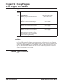
Program 33 : CTA and ACI Setup . . . . . . . . . . . . . . . . . . . . . . . . . . . . . . . . . . . . . 555
33-01 : ACI Port Type Setup . . . . . . . . . . . . . . . . . . . . . . . . . . . . . . . . . . . . . . . 555
33-02 : ACI Department Calling Group . . . . . . . . . . . . . . . . . . . . . . . . . . . . . . 557
Program 34 : Tie Line Setup . . . . . . . . . . . . . . . . . . . . . . . . . . . . . . . . . . . . . . . . . 559
34-01 : E&M Tie Line Basic Setup . . . . . . . . . . . . . . . . . . . . . . . . . . . . . . . . . . 559
34-02 : E&M Tie Line Class of Service . . . . . . . . . . . . . . . . . . . . . . . . . . . . . . 561
34-03 : Trunk Group Routing for E&M Tie Lines . . . . . . . . . . . . . . . . . . . . . . 563
34-04 : E&M Tie Line Toll Restriction Class . . . . . . . . . . . . . . . . . . . . . . . . . . 565
34-05 : Tie Line Outgoing Call Restriction . . . . . . . . . . . . . . . . . . . . . . . . . . . . 567
34-06 : Add / Delete Digit for E&M Tie Line . . . . . . . . . . . . . . . . . . . . . . . . . . 569
34-07 : E&M Tie Line Timer . . . . . . . . . . . . . . . . . . . . . . . . . . . . . . . . . . . . . . . 571
34-08 : Toll Restriction Data for E&M Tie Lines . . . . . . . . . . . . . . . . . . . . . . . 573
34-09 : ANI/DNIS Service Options . . . . . . . . . . . . . . . . . . . . . . . . . . . . . . . . . . 575
34-10 : Digit Delete for T1 ANI . . . . . . . . . . . . . . . . . . . . . . . . . . . . . . . . . . . . 578
Program 35 : SMDR and Account Code Setup . . . . . . . . . . . . . . . . . . . . . . . . . . . 581
35-01 : SMDR Options . . . . . . . . . . . . . . . . . . . . . . . . . . . . . . . . . . . . . . . . . . . 581
35-02 : SMDR Output Options . . . . . . . . . . . . . . . . . . . . . . . . . . . . . . . . . . . . . 583
35-03 : SMDR Port Assignment for Trunk Group . . . . . . . . . . . . . . . . . . . . . . 586
35-04 : SMDR Port Assignment for Department Groups . . . . . . . . . . . . . . . . . 588
35-05 : Account Code Setup . . . . . . . . . . . . . . . . . . . . . . . . . . . . . . . . . . . . . . . 590
35-06 : Verified Account Code Table . . . . . . . . . . . . . . . . . . . . . . . . . . . . . . . . 592
UX5000 Software Program Manual
◆ Table of Contents- 7
Table of Contents
Program 40 : Voice Mail Setup . . . . . . . . . . . . . . . . . . . . . . . . . . . . . . . . . . . . . . . 595
40-01 : Voice Mail Basic Setup . . . . . . . . . . . . . . . . . . . . . . . . . . . . . . . . . . . . . 595
40-02 : Mailbox Setup . . . . . . . . . . . . . . . . . . . . . . . . . . . . . . . . . . . . . . . . . . . . 596
40-03 : Message Recording Setup . . . . . . . . . . . . . . . . . . . . . . . . . . . . . . . . . . . 597
40-04 : Live Recording Setup . . . . . . . . . . . . . . . . . . . . . . . . . . . . . . . . . . . . . . 598
40-05 : Call Information Setup . . . . . . . . . . . . . . . . . . . . . . . . . . . . . . . . . . . . . 599
40-06 : Voice Mail Automated Attendant Data Setup . . . . . . . . . . . . . . . . . . . . 600
40-07 : Voice Prompt Language Assignment for VRS . . . . . . . . . . . . . . . . . . . 601
40-08 : Voice Prompt Language Assignment for Mailboxes . . . . . . . . . . . . . . 603
40-09 : Voice Mail Multiple Address Group Setup . . . . . . . . . . . . . . . . . . . . . . 604
40-10 : Voice Announcement Service Option . . . . . . . . . . . . . . . . . . . . . . . . . . 605
40-11 : Pre-Amble Message Assignment . . . . . . . . . . . . . . . . . . . . . . . . . . . . . 607
40-12 : One Digit Access Setup . . . . . . . . . . . . . . . . . . . . . . . . . . . . . . . . . . . . . 609
Program 41 : ACD Setup . . . . . . . . . . . . . . . . . . . . . . . . . . . . . . . . . . . . . . . . . . . . 610
41-01 : System Options for ACD . . . . . . . . . . . . . . . . . . . . . . . . . . . . . . . . . . . . 610
41-02 : ACD Group and Agent Assignments . . . . . . . . . . . . . . . . . . . . . . . . . . 612
41-03 : Incoming Ring Group Assignment for ACD Group . . . . . . . . . . . . . . . 614
41-04 : ACD Group Supervisor . . . . . . . . . . . . . . . . . . . . . . . . . . . . . . . . . . . . 616
41-05 : ACD Agent Work Schedules . . . . . . . . . . . . . . . . . . . . . . . . . . . . . . . . . 618
41-06 : Trunk Work Schedules . . . . . . . . . . . . . . . . . . . . . . . . . . . . . . . . . . . . . 620
41-07 : ACD Weekly Schedule Setup . . . . . . . . . . . . . . . . . . . . . . . . . . . . . . . . 622
41-08 : ACD Overflow Options . . . . . . . . . . . . . . . . . . . . . . . . . . . . . . . . . . . . . 624
41-09 : ACD Overflow Table Setting . . . . . . . . . . . . . . . . . . . . . . . . . . . . . . . . 627
41-10 : PGDAD Delay Announcement . . . . . . . . . . . . . . . . . . . . . . . . . . . . . . . 629
41-11 : VRS Delay Announcement . . . . . . . . . . . . . . . . . . . . . . . . . . . . . . . . . . 631
41-12 : Night Announcement Setup . . . . . . . . . . . . . . . . . . . . . . . . . . . . . . . . . 633
41-13 : VRS Message Number for Night Announcement . . . . . . . . . . . . . . . . . 635
41-14 : ACD Options . . . . . . . . . . . . . . . . . . . . . . . . . . . . . . . . . . . . . . . . . . . . . 637
41-15 : ACD Queue Alarm Information . . . . . . . . . . . . . . . . . . . . . . . . . . . . . . 641
41-16 : ACD Threshold Overflow . . . . . . . . . . . . . . . . . . . . . . . . . . . . . . . . . . . 643
41-17 : ACD Login Mode Setup . . . . . . . . . . . . . . . . . . . . . . . . . . . . . . . . . . . . 645
41-18 : ACD Agent Identity Code Setup . . . . . . . . . . . . . . . . . . . . . . . . . . . . . . 647
41-19 : Voice Mail Delay Announcement . . . . . . . . . . . . . . . . . . . . . . . . . . . . . 649
41-20 : ACD Queue Display Settings . . . . . . . . . . . . . . . . . . . . . . . . . . . . . . . . 651
Program 42 : Hotel Setup . . . . . . . . . . . . . . . . . . . . . . . . . . . . . . . . . . . . . . . . . . . 653
42-01 : System Options for Hotel/Motel . . . . . . . . . . . . . . . . . . . . . . . . . . . . . . 653
42-02 : Hotel/Motel Terminal Setup . . . . . . . . . . . . . . . . . . . . . . . . . . . . . . . . . 655
42-03 : Class of Service Options (Hotel/Motel) . . . . . . . . . . . . . . . . . . . . . . . . 657
42-04 : Hotel Mode One-Digit Service Codes . . . . . . . . . . . . . . . . . . . . . . . . . . 660
42-05 : Hotel Room Status Printer . . . . . . . . . . . . . . . . . . . . . . . . . . . . . . . . . . . 662
42-07 : PMS Restriction Level Conversion . . . . . . . . . . . . . . . . . . . . . . . . . . . . 664
Table of Contents - 8 ◆
UX5000 Software Program Manual
Table of Contents
Program 44 : ARS/F-Route Setup . . . . . . . . . . . . . . . . . . . . . . . . . . . . . . . . . . . . . 667
44-01 : System Options for ARS/F-Route . . . . . . . . . . . . . . . . . . . . . . . . . . . . . 667
44-02 : Dial Analysis Table for ARS/F-Route Access . . . . . . . . . . . . . . . . . . . 668
44-03 : Dial Analysis Extension Table . . . . . . . . . . . . . . . . . . . . . . . . . . . . . . . 670
44-04 : ARS/F-Route Selection for Time Schedule . . . . . . . . . . . . . . . . . . . . . 672
44-05 : ARS/F-Route Table . . . . . . . . . . . . . . . . . . . . . . . . . . . . . . . . . . . . . . . . 673
44-06 : Additional Dial Table . . . . . . . . . . . . . . . . . . . . . . . . . . . . . . . . . . . . . . 675
44-07 : Gain Table for ARS/F-Route Access . . . . . . . . . . . . . . . . . . . . . . . . . . 676
44-08 : Time Schedule for ARS/F-Route . . . . . . . . . . . . . . . . . . . . . . . . . . . . . 678
44-09 : Weekly Schedule for ARS/F-Route . . . . . . . . . . . . . . . . . . . . . . . . . . . 680
44-10 : Holiday Schedule for ARS/F-Route . . . . . . . . . . . . . . . . . . . . . . . . . . . 682
Program 45 : Voice Mail Integration . . . . . . . . . . . . . . . . . . . . . . . . . . . . . . . . . . . . 683
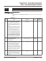
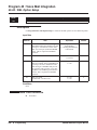
45-01 : Voice Mail Integration Options . . . . . . . . . . . . . . . . . . . . . . . . . . . . . . . 683
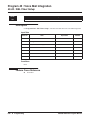
45-02 : NSL Option Setup . . . . . . . . . . . . . . . . . . . . . . . . . . . . . . . . . . . . . . . . . 686
45-03 : NSL Timer Setup . . . . . . . . . . . . . . . . . . . . . . . . . . . . . . . . . . . . . . . . . . 688
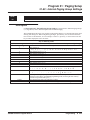
Program 47 : IntraMail . . . . . . . . . . . . . . . . . . . . . . . . . . . . . . . . . . . . . . . . . . . . . . 691
47-01 : IntraMail System Options . . . . . . . . . . . . . . . . . . . . . . . . . . . . . . . . . . . 691
47-02: IntraMail Station Mailbox Options . . . . . . . . . . . . . . . . . . . . . . . . . . . . 696
47-03: IntraMail Group Mailbox Options . . . . . . . . . . . . . . . . . . . . . . . . . . . . . 702
47-06: Group Subscriber Mailbox Options . . . . . . . . . . . . . . . . . . . . . . . . . . . . 704
47-07: IntraMail Routing Mailbox Options . . . . . . . . . . . . . . . . . . . . . . . . . . . . 709
47-08: Call Routing Mailbox Options . . . . . . . . . . . . . . . . . . . . . . . . . . . . . . . . 711
47-09: Announcement Mailbox Options . . . . . . . . . . . . . . . . . . . . . . . . . . . . . . 713
47-10: IntraMail Trunk Options . . . . . . . . . . . . . . . . . . . . . . . . . . . . . . . . . . . . . 715
47-11: IntraMail Answer Table Options . . . . . . . . . . . . . . . . . . . . . . . . . . . . . . 717
47-12: IntraMail Answer Schedules . . . . . . . . . . . . . . . . . . . . . . . . . . . . . . . . . 721
47-13: IntraMail Dial Action Tables . . . . . . . . . . . . . . . . . . . . . . . . . . . . . . . . . 728
47-15 : Routing Directory Mailbox Options . . . . . . . . . . . . . . . . . . . . . . . . . . . 735
47-16 : IntraMail Language Assignments . . . . . . . . . . . . . . . . . . . . . . . . . . . . . 738
47-17 : Routing Distribution Mailbox Options . . . . . . . . . . . . . . . . . . . . . . . . . 740
47-18 : IntraMail SMTP Setup . . . . . . . . . . . . . . . . . . . . . . . . . . . . . . . . . . . . . 742
47-19 : IntraMail POP3 Setup . . . . . . . . . . . . . . . . . . . . . . . . . . . . . . . . . . . . . . 744
Program 51 : CygniLink Service . . . . . . . . . . . . . . . . . . . . . . . . . . . . . . . . . . . . . . 747
51-01 : CygniLink System Settings . . . . . . . . . . . . . . . . . . . . . . . . . . . . . . . . . . 747
51-02 : CygniLink System Individual Setting . . . . . . . . . . . . . . . . . . . . . . . . . . 749
51-03 : CygniLink Internet Protocol Address List Setting . . . . . . . . . . . . . . . . 751
51-04 : IP Address for Top Priority Primary System . . . . . . . . . . . . . . . . . . . . 753
51-05 : Timer Settings for CygniLink . . . . . . . . . . . . . . . . . . . . . . . . . . . . . . . . 755
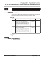
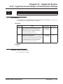
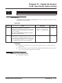
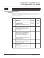
51-06 : CygniLink Primary System Automatic Integration Setting . . . . . . . . . 757
51-07 : CygniLink Forced Change of Primary System Settings . . . . . . . . . . . . 759
UX5000 Software Program Manual
◆ Table of Contents- 9
Table of Contents
51-08 : New Primary System Setting . . . . . . . . . . . . . . . . . . . . . . . . . . . . . . . . . 761
51-09 : CygniLink TCP Port Settings . . . . . . . . . . . . . . . . . . . . . . . . . . . . . . . . 763
51-10 : Remaining Virtual Slots . . . . . . . . . . . . . . . . . . . . . . . . . . . . . . . . . . . . 765
51-11 : CygniLink System Information . . . . . . . . . . . . . . . . . . . . . . . . . . . . . . 766
51-12 : Primary System Information . . . . . . . . . . . . . . . . . . . . . . . . . . . . . . . . . 768
51-13 : CygniLink Option Settings . . . . . . . . . . . . . . . . . . . . . . . . . . . . . . . . . . 770
51-14 : CygniLink System Control . . . . . . . . . . . . . . . . . . . . . . . . . . . . . . . . . . 772
51-15 : Easy Set Command . . . . . . . . . . . . . . . . . . . . . . . . . . . . . . . . . . . . . . . . 774
51-16 : CygniLink System Data Replication Mode Setting . . . . . . . . . . . . . . . 776
Program 80 : Basic Hardware Setup for System . . . . . . . . . . . . . . . . . . . . . . . . . . 779
80-01 : Service Tone Setup . . . . . . . . . . . . . . . . . . . . . . . . . . . . . . . . . . . . . . . . 779
80-02 : DTMF Tone Setup . . . . . . . . . . . . . . . . . . . . . . . . . . . . . . . . . . . . . . . . . 786
80-03 : DTMF Tone Receiver Setup . . . . . . . . . . . . . . . . . . . . . . . . . . . . . . . . . 788
80-04 : Call Progress Tone Detector Setup . . . . . . . . . . . . . . . . . . . . . . . . . . . . 791
80-05 : Date Format for SMDR and System Reports . . . . . . . . . . . . . . . . . . . . 794
80-07 : Call Progress Tone Detector Frequency Setup . . . . . . . . . . . . . . . . . . . 795
80-09 : Short Ring Setup . . . . . . . . . . . . . . . . . . . . . . . . . . . . . . . . . . . . . . . . . . 796
80-10 : MF Tone Receiver Setup . . . . . . . . . . . . . . . . . . . . . . . . . . . . . . . . . . . . 798
Program 81 : Basic Hardware Setup for Trunk . . . . . . . . . . . . . . . . . . . . . . . . . . . 801
81-01 : COIU Initial Data Setup . . . . . . . . . . . . . . . . . . . . . . . . . . . . . . . . . . . . 801
81-02 : DIOPU Initial Data Setup . . . . . . . . . . . . . . . . . . . . . . . . . . . . . . . . . . . 804
81-03 : 4TLIU Initial Data Setup . . . . . . . . . . . . . . . . . . . . . . . . . . . . . . . . . . . . 806
81-04 : ISDN BRI Layer 1 (T-Point) Initial Data Setup . . . . . . . . . . . . . . . . . . 808
81-05 : ISDN BRI & PRI Layer 2 (T-Point) Initial Data Setup . . . . . . . . . . . . 809
81-06 : ISDN BRI & PRI Layer 3 (T-Point) Timer Setup . . . . . . . . . . . . . . . . . 811
81-07 : Codec Filter Setup for Analog Trunk Ports . . . . . . . . . . . . . . . . . . . . . . 813
81-08 : T1 Trunk Timer Setup . . . . . . . . . . . . . . . . . . . . . . . . . . . . . . . . . . . . . . 815
81-09 : COIU Codec Filter Data Setup . . . . . . . . . . . . . . . . . . . . . . . . . . . . . . . 819
Program 82 : Basic Hardware Setup for Extension . . . . . . . . . . . . . . . . . . . . . . . . 821
82-01 : Incoming Ring Tone . . . . . . . . . . . . . . . . . . . . . . . . . . . . . . . . . . . . . . . 821
82-03 : DSS Console LED Pattern Setup . . . . . . . . . . . . . . . . . . . . . . . . . . . . . 824
82-04 : SLIU Initial Data Setup . . . . . . . . . . . . . . . . . . . . . . . . . . . . . . . . . . . . . 826
82-05 : ISDN BRI & PRI Layer 2 (S-Point) Initial Data Setup . . . . . . . . . . . . . 828
82-06 : ISDN BRI & PRI Layer 3 (S-Point) Timer Setup . . . . . . . . . . . . . . . . . 830
82-07 : Codec Filter Setup for Analog Station Ports . . . . . . . . . . . . . . . . . . . . . 832
82-08 : Sidetone Volume Setup . . . . . . . . . . . . . . . . . . . . . . . . . . . . . . . . . . . . . 834
82-09 : SLIU Codec Filter Data Setup . . . . . . . . . . . . . . . . . . . . . . . . . . . . . . . . 836
Table of Contents - 10 ◆
UX5000 Software Program Manual
Table of Contents
Program 84 : Hardware Setup for VoIP . . . . . . . . . . . . . . . . . . . . . . . . . . . . . . . . . 839
84-01 : Codec Information Basic Setup . . . . . . . . . . . . . . . . . . . . . . . . . . . . . . . 839
84-02 : H.225, H.245 Information Basic Setup . . . . . . . . . . . . . . . . . . . . . . . . . 846
84-03 : IP Terminal Information Basic Setup . . . . . . . . . . . . . . . . . . . . . . . . . . 849
84-07 : Firmware Download Setup . . . . . . . . . . . . . . . . . . . . . . . . . . . . . . . . . . 851
84-08 : Firmware Name Setup . . . . . . . . . . . . . . . . . . . . . . . . . . . . . . . . . . . . . . 853
84-09 : VLAN Setup . . . . . . . . . . . . . . . . . . . . . . . . . . . . . . . . . . . . . . . . . . . . . 855
84-10 : ToS Setup . . . . . . . . . . . . . . . . . . . . . . . . . . . . . . . . . . . . . . . . . . . . . . . 857
84-11 : Dterm IP Codec Information Basic Setup . . . . . . . . . . . . . . . . . . . . . . . 859
84-12 : Networking Codec Information Basic Setup . . . . . . . . . . . . . . . . . . . . . 864
84-13 : SIP Trunk Codec Information Basic Setup . . . . . . . . . . . . . . . . . . . . . . 870
84-14 : SIP Trunk Basic Information Setup . . . . . . . . . . . . . . . . . . . . . . . . . . . 876
84-15 : H.323 Keep Alive Setup . . . . . . . . . . . . . . . . . . . . . . . . . . . . . . . . . . . . 878
84-16 : VOIPDB Limiter Control Gain Setup . . . . . . . . . . . . . . . . . . . . . . . . . . 880
84-17 : VOIPDB Echo Canceller Control Setup . . . . . . . . . . . . . . . . . . . . . . . . 882
84-19 : SIP Extension Codec Information Basic Setup . . . . . . . . . . . . . . . . . . . 884
84-20 : SIP Extension Basic Information Setup . . . . . . . . . . . . . . . . . . . . . . . . 890
84-22 : DT700 Logon Information Setup . . . . . . . . . . . . . . . . . . . . . . . . . . . . . 892
84-23 : DT700 Basic Information Setup . . . . . . . . . . . . . . . . . . . . . . . . . . . . . . 894
84-24 : SIP-MLT Codec Information Basic Setup . . . . . . . . . . . . . . . . . . . . . . 896
84-25 : CygniLink Codec Information Basic Setup . . . . . . . . . . . . . . . . . . . . . 901
84-26 : VOIPDB Setup for Each DSP . . . . . . . . . . . . . . . . . . . . . . . . . . . . . . . . 907
84-27 : VOIPDB Setup . . . . . . . . . . . . . . . . . . . . . . . . . . . . . . . . . . . . . . . . . . . 909
84-28 : DT700 Firmware Name Setup . . . . . . . . . . . . . . . . . . . . . . . . . . . . . . . . 911
84-29 : SIP-MLT Codec Information Fixed Mode Setup . . . . . . . . . . . . . . . . . 913
Program 90 : Maintenance Program . . . . . . . . . . . . . . . . . . . . . . . . . . . . . . . . . . . 915
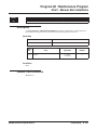
90-01 : Installation Date . . . . . . . . . . . . . . . . . . . . . . . . . . . . . . . . . . . . . . . . . . . 915
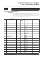
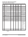
90-02 : Setting the Programming Password . . . . . . . . . . . . . . . . . . . . . . . . . . . . 916
90-03 : Save Data . . . . . . . . . . . . . . . . . . . . . . . . . . . . . . . . . . . . . . . . . . . . . . . . 918
90-04 : Load Data . . . . . . . . . . . . . . . . . . . . . . . . . . . . . . . . . . . . . . . . . . . . . . . 919
90-05 : Slot Control . . . . . . . . . . . . . . . . . . . . . . . . . . . . . . . . . . . . . . . . . . . . . . 921
90-06 : Trunk Control . . . . . . . . . . . . . . . . . . . . . . . . . . . . . . . . . . . . . . . . . . . . 923
90-07 : Extension Control . . . . . . . . . . . . . . . . . . . . . . . . . . . . . . . . . . . . . . . . . 925
90-08 : System Reset . . . . . . . . . . . . . . . . . . . . . . . . . . . . . . . . . . . . . . . . . . . . . 926
90-09 : Automatic System Reset Time . . . . . . . . . . . . . . . . . . . . . . . . . . . . . . . 927
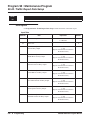
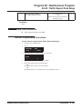
90-10 : System Alarm Setup . . . . . . . . . . . . . . . . . . . . . . . . . . . . . . . . . . . . . . . 929
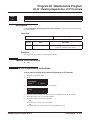
90-11 : System Alarm Report . . . . . . . . . . . . . . . . . . . . . . . . . . . . . . . . . . . . . . 937
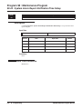
90-12 : System Alarm Output . . . . . . . . . . . . . . . . . . . . . . . . . . . . . . . . . . . . . . 939
90-13 : System Information Output . . . . . . . . . . . . . . . . . . . . . . . . . . . . . . . . . . 941
90-16 : Main Software Information . . . . . . . . . . . . . . . . . . . . . . . . . . . . . . . . . . 943
90-17 : Firmware Information . . . . . . . . . . . . . . . . . . . . . . . . . . . . . . . . . . . . . . 944
UX5000 Software Program Manual
◆ Table of Contents- 11
Table of Contents
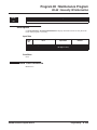
90-19 : Dial Block Release . . . . . . . . . . . . . . . . . . . . . . . . . . . . . . . . . . . . . . . . 945
90-20 : Traffic Report Data Setup . . . . . . . . . . . . . . . . . . . . . . . . . . . . . . . . . . . 946
90-21 : Traffic Report Output . . . . . . . . . . . . . . . . . . . . . . . . . . . . . . . . . . . . . . 948
90-22 : NGT Terminal Version Information . . . . . . . . . . . . . . . . . . . . . . . . . . . 949
90-23 : Deleting Registration of IP Terminals . . . . . . . . . . . . . . . . . . . . . . . . . . 951
90-24 : System Alarm Report Notification Time Setup . . . . . . . . . . . . . . . . . . 952
90-25 : System Alarm Report CC Mail Setup . . . . . . . . . . . . . . . . . . . . . . . . . . 954
90-26 : Program Access Level Setup . . . . . . . . . . . . . . . . . . . . . . . . . . . . . . . . . 955
90-28 : UserPro Password Setup . . . . . . . . . . . . . . . . . . . . . . . . . . . . . . . . . . . . 957
90-31 : DIM Over Ethernet . . . . . . . . . . . . . . . . . . . . . . . . . . . . . . . . . . . . . . . . 958
90-34 : Firmware Information . . . . . . . . . . . . . . . . . . . . . . . . . . . . . . . . . . . . . . 960
90-35 : Wizard Programming Level Setup . . . . . . . . . . . . . . . . . . . . . . . . . . . . 961
90-36 : Firmware Update Time Setting . . . . . . . . . . . . . . . . . . . . . . . . . . . . . . . 963
90-38 : UserPro Data Level Setup . . . . . . . . . . . . . . . . . . . . . . . . . . . . . . . . . . . 965
90-39 : Virtual Loopback Port Reset . . . . . . . . . . . . . . . . . . . . . . . . . . . . . . . . . 968
90-41 : Server Settings to Update Terminal Local Data . . . . . . . . . . . . . . . . . . 970
90-42 : DT700 Terminal Version Information . . . . . . . . . . . . . . . . . . . . . . . . . 972
90-43 : Deleting Terminal License of DT700 . . . . . . . . . . . . . . . . . . . . . . . . . . 974
90-44 : Deleting Terminal License of TCP Interface . . . . . . . . . . . . . . . . . . . . 976
90-45 : Temporary Password Change for DT700 Terminal . . . . . . . . . . . . . . . 978
90-48 : Button Kit Information of Multi-Line Terminal . . . . . . . . . . . . . . . . . . 979
90-49 : Protection Mode Setup for Multi-Line Terminal . . . . . . . . . . . . . . . . . 981
90-50 : System Alarm Display Setup . . . . . . . . . . . . . . . . . . . . . . . . . . . . . . . . . 983
90-51 : Alarm Setup for Maintenance Exchange . . . . . . . . . . . . . . . . . . . . . . . . 984
90-52 : System Alarm Output . . . . . . . . . . . . . . . . . . . . . . . . . . . . . . . . . . . . . . 986
90-53 : Clear System Alarm Reports . . . . . . . . . . . . . . . . . . . . . . . . . . . . . . . . 987
90-55 : Free License Activation . . . . . . . . . . . . . . . . . . . . . . . . . . . . . . . . . . . . . 988
90-56 : NTP Setup . . . . . . . . . . . . . . . . . . . . . . . . . . . . . . . . . . . . . . . . . . . . . . . 989
90-57 : Backup Recovery Data . . . . . . . . . . . . . . . . . . . . . . . . . . . . . . . . . . . . . 990
90-58 : Restore Recovery Data . . . . . . . . . . . . . . . . . . . . . . . . . . . . . . . . . . . . . 992
90-59 : Delete Recovery Data . . . . . . . . . . . . . . . . . . . . . . . . . . . . . . . . . . . . . . 994
90-60 : T1/ISDN Layer Status Information . . . . . . . . . . . . . . . . . . . . . . . . . . . . 995
90-61 : Manual Slot Installation . . . . . . . . . . . . . . . . . . . . . . . . . . . . . . . . . . . . 997
90-62 : Security ID Information . . . . . . . . . . . . . . . . . . . . . . . . . . . . . . . . . . . . 999
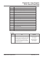
Program 92 : Copy Program . . . . . . . . . . . . . . . . . . . . . . . . . . . . . . . . . . . . . . . . 1001
92-01 : Copy by Extension Number . . . . . . . . . . . . . . . . . . . . . . . . . . . . . . . . 1001
92-02 : Delete All Extension Numbers . . . . . . . . . . . . . . . . . . . . . . . . . . . . . . 1006
92-03 : Copy by Port Number . . . . . . . . . . . . . . . . . . . . . . . . . . . . . . . . . . . . . 1007
92-04 : Extension Data Swap . . . . . . . . . . . . . . . . . . . . . . . . . . . . . . . . . . . . . . 1010
Table of Contents - 12 ◆
UX5000 Software Program Manual
Table of Contents
92-05 : Data Swap Password . . . . . . . . . . . . . . . . . . . . . . . . . . . . . . . . . . . . . . 1013
92-06 : Fill Extension Data . . . . . . . . . . . . . . . . . . . . . . . . . . . . . . . . . . . . . . . 1016
92-07 : Delete Port Data . . . . . . . . . . . . . . . . . . . . . . . . . . . . . . . . . . . . . . . . . 1018
Program 99 : Manufacturer Options . . . . . . . . . . . . . . . . . . . . . . . . . . . . . . . . . . . 1021
99-01 : MF Options . . . . . . . . . . . . . . . . . . . . . . . . . . . . . . . . . . . . . . . . . . . . . 1021
99-02 : Nondisclosure Options Firmware Download . . . . . . . . . . . . . . . . . . . 1024
UX5000 Software Program Manual
◆ Table of Contents- 13
Table of Contents
- For Your Notes -
Table of Contents - 14 ◆
UX5000 Software Program Manual
Introduction to Programming
Before You Start Programming
Introduction to Programming
Before You Start Programming
Before Reading This Section
This manual provides you with detailed information about the UX5000 programs. By changing a
program, you change the way the feature associated with that program works. In this manual, you
find out about each program, the features that the program affects and how to enter the program
data into UX5000 memory.
Do not start customizing your UX5000 without first reading the
UX5000 Software Features Manual, P/N 0913201.
When you want to customize a feature, find it in Software Features Manual and learn about it. The
Software Features Manual will tell you what programs you have to change to get the operation you
want. Then, look the program up in this manual if you have any questions about how to enter the
data.
How to Use This Section
This manual lists each program in numerical order. For example, Program 10-01 is at the beginning
of the manual and Program 92-01 is at the end. The information on each program is subdivided into
the following headings:
Description describes what the program options control. The Default Settings for each program are
also included. When you first install the UX5000, it uses the Default Setting for all programs.
Along with the Description are the Conditions which describe any limits or special considerations
that may apply to the program.
The reverse type (white on black) just beneath the Description heading is the program’s access
level. You can only use the program if your access level meets or exceeds the level the program
requires. Refer to How to Enter the Programming Mode (page 2) for a list of the UX5000’s
access levels and passwords.
Feature Cross Reference provides you with a table of all the features affected by the program.
You’ll want to keep the referenced features in mind when you change a program. Customizing a
feature may have an effect on another feature that you didn’t intend.
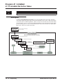
Terminal Programming Instructions shows you how to enter the program’s data into UX5000
memory. For example:
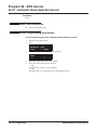
1. Enter the programming mode.
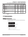
2. 15-07-01
15-07-01 TEL301
KY01 = *01
←
→
tells you to enter the programming mode, dial 150701 from the terminal dial pad. After you do,
you’ll see the message “15-07-01 TEL301” on the first line of the terminal display. This indicates
the program number (15-07), item number (01), and that the options are being set for extension
301. The second row of the display “KY01 = *01” indicates that Key 01 is being programmed with
the entry of *01. The third row allows you to move the cursor to the left or right, depending on
which arrow is pressed. To learn how to enter the programming mode, see How to Enter the Programming Mode below.
UX5000 Software Program Manual
Programming ◆ 1
Introduction to Programming
Before You Start Programming
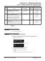
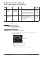
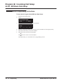
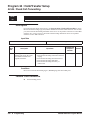
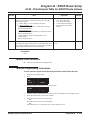
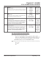
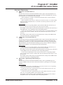
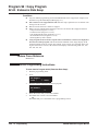
How to Enter the Programming Mode
To enter the programming mode:
1.
2.
3.
Go to any working display terminal.
In a newly installed UX5000, use extension 301 (port 1).
Programming access may be restricted based on the type of program entry used and if
other users are connected to the UX5000 for programming purposes.
PC Pro: Only one user allowed access to the UX5000 programming at a time.
WebPro: Up to 4 WebPro or TelPro users can be connected at the same time.
TelPro: Up to 4 TelPro or WebPro users can be connected at the same time.
Do not lift the handset.
Press CALL1.
4.
#*#*
Password
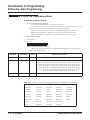
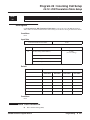
5.
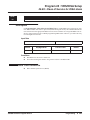
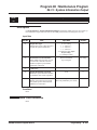
Dial the UX5000 password + HOLD.
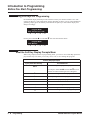
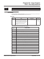
Refer to the following table for the default UX5000 passwords. To change the passwords, use Program 90-02.
Password
User Name
Level
Programs at this Level
12345678
UX5000
2 (IN)
All programs in this section not listed below for SA and SB
0000
ADMIN1
3 (SA)
10-01, 10-02, 10-12, 10-13, 10-14, 10-15, 10-16, 10-17, 10-18, 10-22,
10-23, 10-24, 10-25, 10-27, 10-28, 10-29, 10-31, 12-02, 12-03, 12-04,
12-08, 13-04, 13-05, 15-01, 15-07, 15-09, 15-10, 15-11, 15-14, 20-16,
20-34, 21-07, 21-14, 22-04, 22-11, 22-17, 25-08, 30-03, 30-04, 32-02,
40-02, 41-02, 41-03, 41-04, 41-05, 41-06, 41-07, 41-08, 41-09, 41-10,
41-11, 41-12, 41-13, 41-14, 41-15, 41-16, 41-17, 41-18, 41-19, 41-20,
45-02, 45-03, 84-22, 90-03, 90-04, 90-06, 90-07, 90-19
9999
ADMIN2
4 (SB)
13-04, 13-05, 15-14
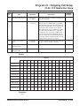
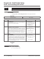
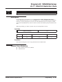
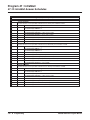
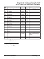
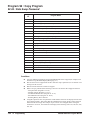
Note: When changes are made to the following programs, the UX5000 must be restarted.
2 ◆ Programming
10-12-01
10-16-01
80-02-03
84-04
84-06-07
10-12-02
10-16-02
80-02-04
84-05-01
84-06-08
10-12-03
10-16-03
80-03
84-05-02
84-06-09
10-12-04
10-16-04
80-04
84-06-01
84-06-10
10-13-01
20-01-03
84-03-01
84-06-02
84-06-11
10-13-02
47-01-01
84-03-02
84-06-03
84-09
10-13-03
80-01
84-03-06
84-06-04
84-10
10-14
80-02-01
84-03-07
84-06-05
10-15
80-02-02
84-03-08
84-06-06
UX5000 Software Program Manual
Introduction to Programming
Before You Start Programming
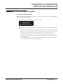
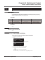
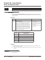
How to Exit the Programming Mode
To exit the programming mode:
When you are done programming, you must be out of a program’s options to exit (pressing the MIC
key will exit the program’s option).
1.
Press MIC key to exit the program’s options, if needed.
Program Mode
Base Service OP1 OP2
2.
3.
Press SPK. You see, "Saving System Data".
The display shows "Complete Data Save" when completed and will exit the terminal to an idle
mode.
To save a customer’s database, plug a USB thumb drive into the CPU and, using Program 90-03, save the software to the USB drive. (Program 90-04 is used to reload the customer data if necessary.) Note that a USB thumb drive can only hold one customer
database unless the files are moved into a separate folder on the thumb drive after it is
saved from the UX5000. Otherwise, the next time a database is saved, it will override the
existing database.
Users are automatically logged out of terminal programming and WebPro when there
is no activity based on the entry in Program 20-01-12.
UX5000 Software Program Manual
Programming ◆ 3
Introduction to Programming
Before You Start Programming
Using Keys to Move Around in the Programs
Once you enter the programming mode, use the keys in the following chart to enter data, edit data
and move around in the menus.
Keys for Entering Data
Use this key...
0-9 and *
When you want to . . .
Enter data into a program.
HOLD
Complete the programming step you just made (like pressing Enter on a PC
keyboard). When a program entry displays, press HOLD to bypass the entry
without changing it.
CONF
Delete the entry to the left (like pressing Backspace on a PC keyboard).
MIC
Exit one step at a time from the program window currently being viewed.
For example, if you’re programming item 5 in 15-03, pressing MIC will
allow you to enter a new option in program 15-03. Pressing MIC again will
allow you to select a new program in the 15- series. Pressing MIC a third
time will allow you to enter a new program beginning with ‘1’. Pressing
MIC one last time will bring you to the beginning program display, allowing
you to enter any program number.
FLASH
Switch extension, line, etc. being programmed by pressing FLASH. The
cursor moves up to the top row of the display. Pressing FLASH again moves
the cursor back to the middle row.
LINE KEYS
Use pre-programmed settings to help with the program entry. These settings
vary between programs from LINE 1 = 0 (off) and LINE 2 = 1 (on) to preset
values for timers where LINE 1 = 5, LINE 2 = 10, LINE 3 = 15, etc.
For programs with this option, the line key which currently matches the programmed setting will light steady.
The display may also indicate Soft Keys which will allow you to select the
values as well (-1 and +1 will step through these pre-programmed settings.)
LINE KEY 1
Program a pause into an Abbreviated Dialing bin.
LINE KEY 2
Program a recall/flash into an Abbreviated Dialing bin.
LINE KEY 3
Program a @ into an Abbreviated Dialing bin.
VOL ▲
Scroll backward through a list of entry numbers (e.g., from extension 301 to
302, 303, etc.) or through entries in a table (e.g., Common Permit Table).
If you enter data and then press this key, the UX5000 accepts the data before
scrolling forward.
VOL ▼
Scroll forward through a list of entry numbers (e.g., from extension 301 to
302, 303, etc.) or through entries in a table (e.g., Common Permit Table).
If you enter data and then press this key, the UX5000 accepts the data before
scrolling backward
4 ◆ Programming
UX5000 Software Program Manual
Introduction to Programming
Before You Start Programming
Programming Names and Text Messages
Several programs (e.g., Program 20-16: Selectable Display Messages) require you to enter text. Use
the following chart when entering and editing text. When using the keypad digits, press the key once
for the first character, twice for the second character, etc. For example, to enter a C, press key “2”
three times. Press the key six times display the lower case letter. The name can be up to 12 digits
long.
Use this keypad digit . . .
1
2
3
4
5
6
7
8
9
0
*
#
CONF
CLEAR
When you want to. . .
Enter characters:
1 @ [ ¥ ] ^ _ ` { | } → ← Á À Â Ã Æ Ç É Ê ì ó 0
Enter characters A-C, a-c, 2.
Enter characters D-F, d-f, 3.
Enter characters G-I, g-i, 4.
Enter characters J-L, j-l, 5.
Enter characters M-O, m-o, 6.
Enter characters P-S, p-s, 7.
Enter characters T-V, t-v, 8.
Enter characters W-Z, w-z, 9.
Enter characters:
0 ! “ # $ % & ’ ( ) ô Õ ú å ä
ö ü α ε θ
Enter characters:
* + , - . / : ; < = > ? π ∑ σ Ω ∞ ¢ £
# = Accepts an entry (only required if two letters on the same key are needed - ex: TOM).
Pressing # again = Space. (In UX5000 programming mode, use the right arrow soft key
instead to accept and/or add a space.)
Clear the character entry one character at a time.
Clear all the entries from the point of the flashing cursor and to the right.
UX5000 Software Program Manual
Programming ◆ 5
Introduction to Programming
Before You Start Programming
Using Soft Keys For Programming
Each UX5000 display terminal provides interactive soft keys for intuitive feature access. The
options for these keys will automatically change depending on where you are in the UX5000 programming. Simply press the Soft Key located below the option you wish and the display will
change accordingly.
_
Program Mode
Base Service OP1 OP2
❍ ❍ ❍ ❍
Pressing the VOLUME ▲ or VOLUME ▼ will scroll between the menus.
_
Program Mode
Hard Mtnance
❍ ❍ ❍ ❍
What the Soft Key Display Prompts Mean
When using a display terminal in programming mode, you will see various Soft Key options displayed. These keys will allow you to easily select, scan, or move through the programs.
Soft key Display Prompts
If you press this Soft Key . . .
back
The UX5000 will. . .
Go back one step in the program display.
You can press VOLUME ▲ or VOLUME ▼ to scroll
forwards or backwards through a list of Programs.
↑
↓
select
←
→
−1
+1
6 ◆ Programming
Scroll down through the available programs.
Scroll up through the available programs.
Select the currently displayed program.
Move the cursor to the left.
Move the cursor to the right.
Move back through the available program options.
Move forward through the available program options.
UX5000 Software Program Manual
Introduction to Programming
Before You Start Programming
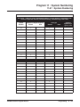
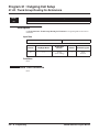
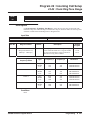
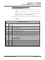
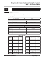
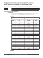
Number Plan/Capacities
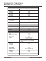
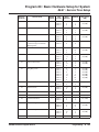
Table 1: System Number Plan/Capacities
System Type:
UX5000 Capacity
System
Analog Caller ID Detector
64
Classes of Service
15
Conference Bridge Groups
4
Day/Night Mode Numbers
8
Day/Night Service Patterns
32
Dial Tone Detector
DTMF Receiver
48 or 64 w/EXIFU-B1 Mounted
Network Nodes:
• CygniLink
• AspireNet
System Ports
(trunks and analog/digital/IP
extensions)
16
50
200 trunks and
512 extensions
* Chassis must be networked to reach max.
Toll Restriction Classes
15
Verifiable Account Code Table
2000
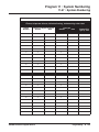
Trunk
Trunk Port Number
Trunk Ports (Total)
• Analog Trunks
• BRI Trunk Ports
• T1/PRI Trunk Ports
• E&M Analog Trunk Ports
• DID Analog Trunk Ports
• VoIP Trunk Ports
BRIU Logical Ports
COIU:
• Physical Ports
• Logical Ports
DIOPU:
• Physical Ports
• Logical Ports
PRIU Logical Ports
UX5000 Software Program Manual
1-200
* A CCPU without a MEMDB, the trunks count
toward the total number of allowed hardware
ports (64).
19” Chassis x 4
184
184
200
92
92
128
Networked Chassis
200
200
200
200
200
128
T-Bus: 1-200
S-Bus: 1-256
01-08
0-200
01-04
LD Trunk: 0-200
OPX: 0-256
T-Bus: 1-200
S-Bus: 1-256
Programming ◆ 7
Introduction to Programming
Before You Start Programming
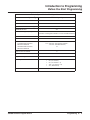
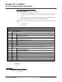
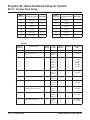
Table 1: System Number Plan/Capacities
System Type:
UX5000 Capacity
TLIU:
• Physical Ports
• Logical Ports
01-04
0-200
VOIPDB:
• Physical Ports
• Logical Ports
001-128
0-200
DID Translation Tables
20
DID Translation Table Entries
2000
DISA
• Classes of Service
• Users
15
1-15
Ring Groups
1-100
Tie Line Classes of Service
15
Tie Line Toll Restriction Classes
15
Trunk Access Maps
1-200
Trunk Group Numbers
1-100
Trunk Routes
1-100
Extension
Telephone Extension Port Numbers
• Keysets
• Single Line Phones/Analog
Devices
• VoIP Extensions
• IP DECT
1-384
(1-384)
(1-384)
(1-512) 5
001-512 (manual select) 5
385-512 (auto select) 5
* A CCPU without a MEMDB, the trunks count
toward the total number of allowed hardware
ports (64).
ESIU
• Physical Ports
• Logical Ports
-Tone Ringer (2PGDAD)
-Door Box (2PGDAD)
-Analog I/F (2PGDAD)
-ACI (2PGDAD)
-APR for B2 Mode
SLIU
• Physical Ports
• Logical Ports
Telephone Extension Number Range
8 ◆ Programming
01-16
1-8
1-8
1-96
1-96
193-512 (descending order)
01-16
1-256
301-499
5000-5312
UX5000 Software Program Manual
Introduction to Programming
Before You Start Programming
Table 1: System Number Plan/Capacities
System Type:
UX5000 Capacity
Virtual Extension Ports
256
Virtual Extension Port Numbers
001-256
Virtual Extension Number Range
Undefined
2PGDAD Modules
ADA (Recording Jack) Adapters
512
512
(104 max. with digital terminals/ 512 max with IP terminals)
Door Boxes
8
Door Box Numbers
DSS Consoles Numbers
• 16-Button DLS Consoles,
Maximum Installed
• 60-Button DSS Consoles,
Maximum Installed
1-8
8
512 (384 max. with digital terminals /
512 max. with IP terminals)
32
Operator Access Number
0
Operator Extension
1-8
Ringdown Assignments
512
SLT Adapters
Voice Mail Master Numbers
UX5000 Software Program Manual
•
•
•
•
•
32 (9.5” Chassis)
80 (19” Chassis)
96 (19” Chassis x 2)
368 (19” Chassis x 4)
512 (Networked)
301-499, 5000-5312
Programming ◆ 9
Introduction to Programming
Before You Start Programming
Table 1: System Number Plan/Capacities
System Type:
UX5000 Capacity
Abbreviated Dialing
Abbreviated Dialing Groups
Abbreviated Dialing Bins
Abbreviated Dialing Table-Common
64
0-1999
1000
ACD
ACD Groups
64
ACD Agent Extensions
512
ACI
ACI Groups
16
ACI Ports
96
Automated Attendant
VRS Message Numbers
1-100
Bluetooth Adapters
BCH - Bluetooth Cordless Handset
16
BHA - Bluetooth Hub Adapter
16
Conference
Conference Circuits
64 - maximum
(32 Parties Per
Conference)
Data Communication Interfaces
APR Software Port Numbers
193-512
APA Adapters-Aspire Version
192 (only on Aspire phones)
APR Adapters-UX5000 Version
CTA or CTU Adapters-Aspire Version
CTE
Module Extension Number Range
32
128 (only on Aspire phones)
128
301-499, 5000-5312
Department and Pickup Groups
Department (Extension) Group
Numbers
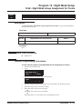
1-64
Department (Extension) Group
Number Range
301-499, 5000-5312
Call Pickup Group Numbers
10 ◆ Programming
1-64
UX5000 Software Program Manual
Introduction to Programming
Before You Start Programming
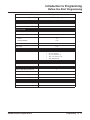
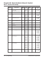
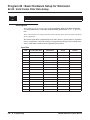
Table 1: System Number Plan/Capacities
System Type:
UX5000 Capacity
Hotline
Internal Hotline
512
External Hotline
512
Paging and Park
Internal Page Group Numbers
0, 1-9 or 01-64
External Page Group Numbers
0, 1-8
External Speakers
• CCPU
• PGDAD Module
9
(1)
(1-8)
Park Group Numbers
1-64
Park Orbits
1-64
Power Failure Adapters
PSA (Power Failure) Adapters
•
•
•
•
•
16 (9.5” Chassis)
40 (19” Chassis)
88 (19” Chassis x 2)
184 (19” Chassis x 4)
200 (Networked)
SMDR
SMDR Ports
1-8
VRS
VRS (on DSP Daughter Board)
VRS Channels
VRS Attendant Messages
VRS Recordable Messages
1
16 (shared with voice mail)
3
100
Voice Mail
Ports for UX IntraMail
4-16
Ports for UX Mail
4-16
UX5000 Software Program Manual
Programming ◆ 11
Introduction to Programming
Before You Start Programming
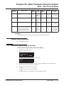
Table 1: System Number Plan/Capacities
System Type:
UX5000 Capacity
VoIP
VoIP Extensions
512
Gigabit Adapters
512
IP Phones
512
RAS Unicast Ports
0-65535
Call Signaling Ports
0-65535
NGT Signal Receive Ports
0-65535
IP Call Procedure Port
0-65535
H.323 Alias Addresses
1-6
Note:
Extension numbers can be three or four digits long. See Flexible System Numbering.
Table1: UX5000 Password
Passwords
User Password for setting Toll Restriction Override and Changing Class of Service
using a service code
0000
Programming Passwords
Level 2 (IN)
PCPro/WebPro User Name:
12345678
UX5000
Level 3 (SA)
PCPro/WebPro User Name:
0000
ADMIN1
Level 4 (SB)
PCPro/WebPro User Name:
9999
ADMIN2
Level 5 (UA)
UserPro UA Level User Name:
1111
USER1
Level 6 (UB)
UserPro UB Level User Name:
1111
xxxxxxxx (Ext. Number)
Programming Password Users
12 ◆ Programming
8
UX5000 Software Program Manual
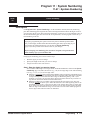
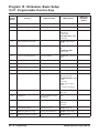
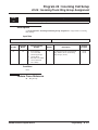
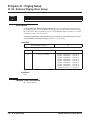
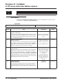
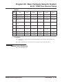
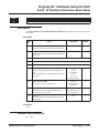
Program 10 : System Configuration Setup
10-01 : Time and Date
Program 10 : System Configuration Setup
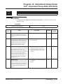
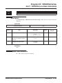
10-01 : Time and Date
Level:
Feature Availability
SA
•
Available.
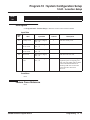
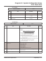
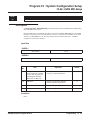
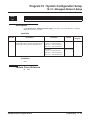
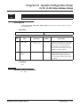
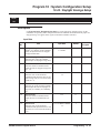
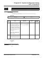
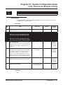
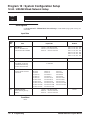
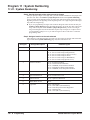
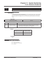
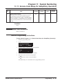
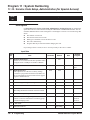
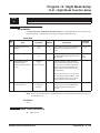
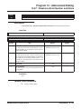
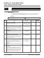
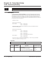
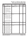
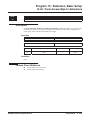
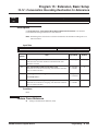
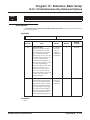
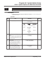
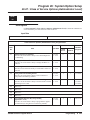
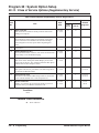
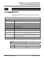
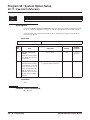
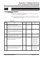
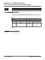
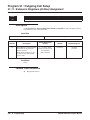
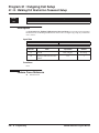
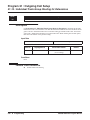
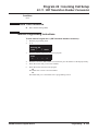
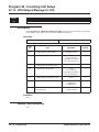
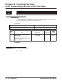
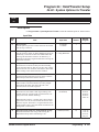
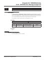
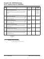
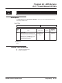
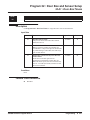
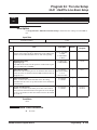
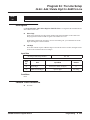
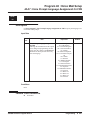
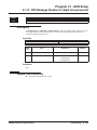
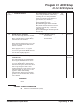
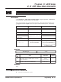
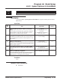
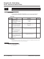
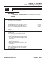
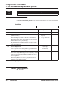
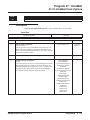
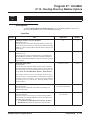
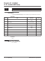
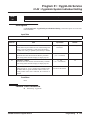
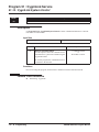
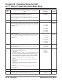
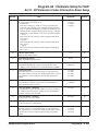
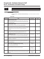
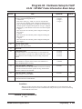
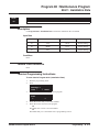
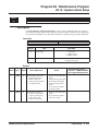
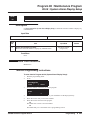
Description
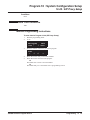
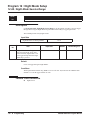
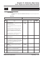
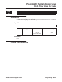
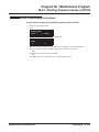
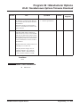
Use Program 10-01 : Time and Date to change the UX5000 Time and Date through UX5000 programming. Extension users can also dial Service Code 828 to change the Time if allowed by an
extension’s Class of Service.
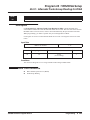
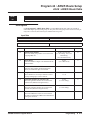
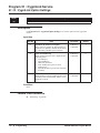
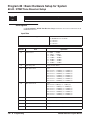
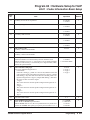
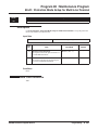
Input Data
Item
No.
Item
Input data
Default
01
Year
00-99
No setting
Enter two digits for year (00-99).
02
Month
01-12
No setting
Enter two digits (01-12) for the month.
03
Day
01-31
No setting
Enter two digits (01-31) for the day.
04
Week
1-7
(Sun-Sat)
No setting
Enter digit for the day of the week
(1=Sunday, 7=Saturday).
05
Hour
00-23
No setting
Enter two digits for the hour (00-23).
06
Minute
00-59
No setting
Enter two digits for the minute (00-59).
07
Second
00-59
No setting
Enter two digits for the second (00-59).
Description
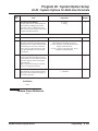
Conditions
None
Feature Cross Reference
●
Time and Date
UX5000 Software Program Manual
Programming ◆ 13
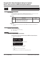
Program 10 : System Configuration Setup
10-01 : Time and Date
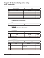
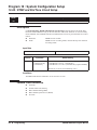
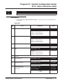
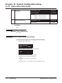
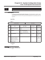
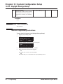
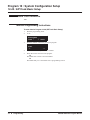
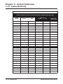
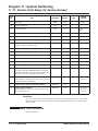
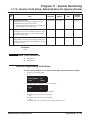
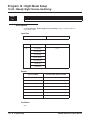
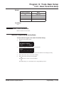
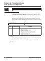
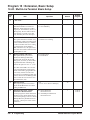
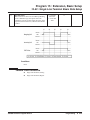
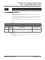
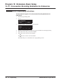
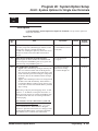
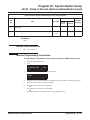
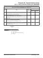
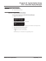
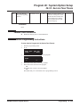
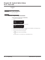
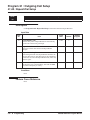
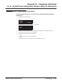
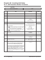
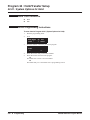
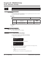
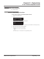
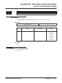
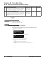
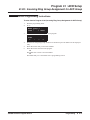
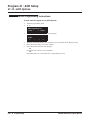
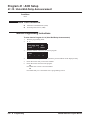
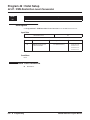
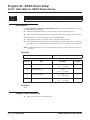
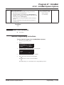
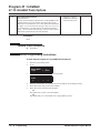
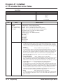
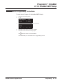
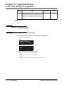
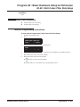
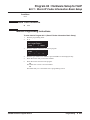
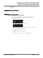
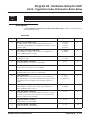
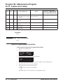
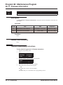
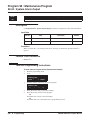
Terminal Programming Instructions
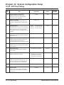
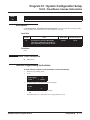
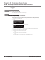
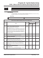
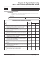
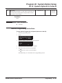
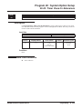
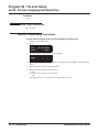
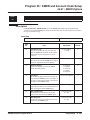
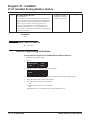
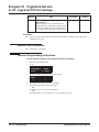
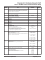
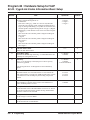
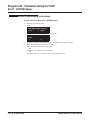
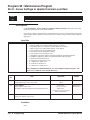
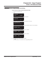
To enter data for Program 10-01 (Time and Date):
1.
2.
Enter the programming mode.
10 01
10-01-01
Year
back
↑
3.
←
14 ◆ Programming
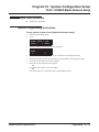
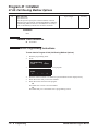
select
Enter the number of the item you want to program.
10-01-nn
nnnnn
4.
5.
↓
→
Enter data for the item you selected + HOLD.
Enter data for the next item in the program.
OR
Press MIC once to enter a new item number.
OR
Press MIC until you’ve exited that series’s programming section.
UX5000 Software Program Manual
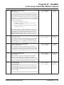
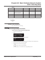
Program 10 : System Configuration Setup
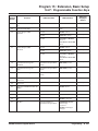
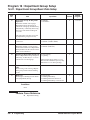
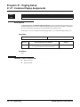
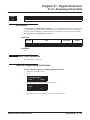
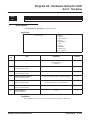
10-02 : Location Setup
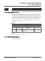
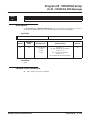
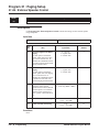
10-02 : Location Setup
Level:
Feature Availability
SA
•
Available.
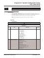
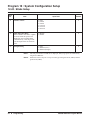
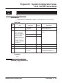
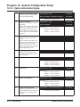
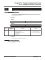
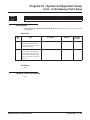
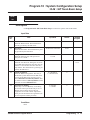
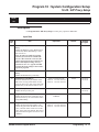
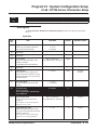
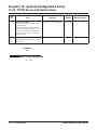
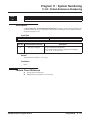
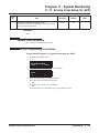
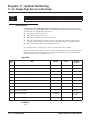
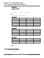
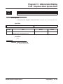
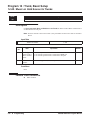
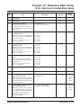
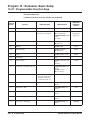
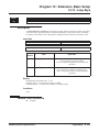
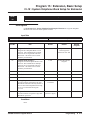
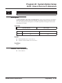
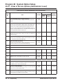
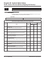
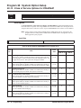
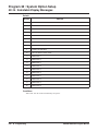
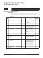
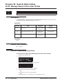
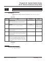
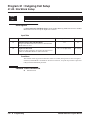
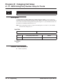
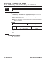
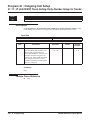
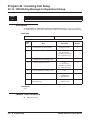
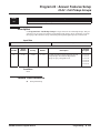
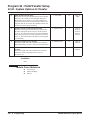
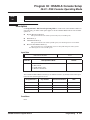
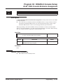
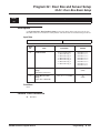
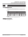
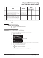
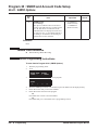
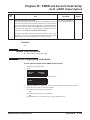
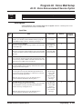
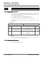
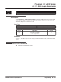
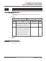
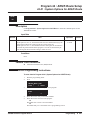
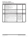
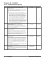
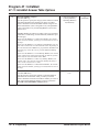
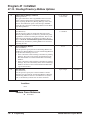
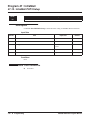
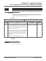
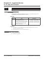
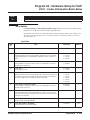
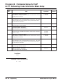
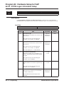
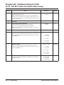
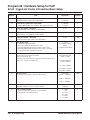
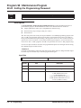
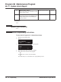
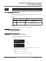
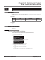
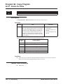
Description
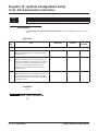
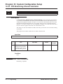
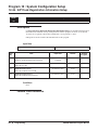
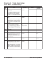
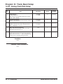
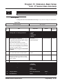
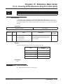
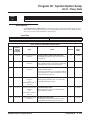
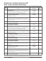
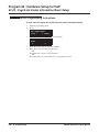
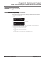
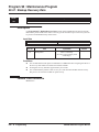
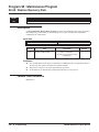
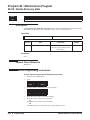
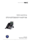
Use Program 10-02 : Location Setup to define the location of the installed UX5000.
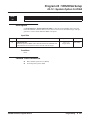
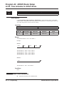
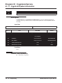
Input Data
Item
No.
Item
Input data
Default
Description
01
Country Code
Dial (up to 4 digits):
0-9, *, #
1
Enter the country code.
02
International
Access Code
Dial (up to 4 digits):
0-9, *, #
-
Enter the international access code.
03
Other Area
Access Code
Dial (up to 2 digits):
0-9, *, #
9
Enter the other area access code
04
Area Code
Dial (up to 6 digits):
0-9, *, #
-
Enter the local area code.
05
Trunk Access
Code
Dial (up to 8 digits):
0-9, *, #
-
Enter the trunk access code digits
required to place an outgoing call.
This is the code which will be added
to the Caller ID information for
incoming trunk calls to allow the
call to dial out if allowed in
20-19-03.
Conditions
None
Feature Cross Reference
None
UX5000 Software Program Manual
Programming ◆ 15
Program 10 : System Configuration Setup
10-02 : Location Setup
Terminal Programming Instructions
To enter data for Program 10-02 (Location Setup):
1.
2.
Enter the programming mode.
10 02
10-02-01
Country_Code
back
↑
↓
3.
Enter the number of the item you want to program.
10-02-nn
nnnnn
←
4.
5.
16 ◆ Programming
select
→
Enter data for the item you selected + HOLD.
Enter data for the next item in the program.
OR
Press MIC once to enter a new item number.
OR
Press MIC until you’ve exited that series’s programming section.
UX5000 Software Program Manual
Program 10 : System Configuration Setup
10-03 : Blade Setup
10-03 : Blade Setup
Level:
Feature Availability
IN
•
Available.
Description
Use Program 10-03 : Blade Setup to setup and confirm the Basic Configuration data for each
blade. When changing a defined terminal type, first set the type to ‘0’ and then plug the new device
in to have the UX5000 automatically define it or you may have to reseat the blade.
Note: The items highlighted in gray are read only and cannot be changed.
Input Data
For ESIU Blade
Physical Port Number
01-16
B-Channel 1
Item
No.
Item
Input Data
Default
01
Terminal Type
0 = Not set
1 = Keyset/DSLT
2 = SLT Adapter
3 = -- Not used -4 = -- Not used -5 = -- Not used -6 = PGD (Paging)
7 = PGD (Tone Ringer)
8 = PGD (Door Box)
9 = PGD (ACI)
10 = DSS Console
11 = -- Not used --
0
02
Logical Port Number
0 = Not set
1 = Keyset (1-256)
2 = SLT Adapter (1-256)
3 = Not used
4 = Not used
5 = Not used
6 = PGD (Paging) (1-8)
7 = PGD (for Tone Ringer) (1-8)
8 = PGD (for Door Box) (1-8)
9 = PGD (for Analog I/F) (1-96)
10 = DSS (1-32)
11 = Not used
0
UX5000 Software Program Manual
Programming ◆ 17
Program 10 : System Configuration Setup
10-03 : Blade Setup
03
Additional Data
This option is reserved for future use.
3 = Not used
4 = Not used
01-16 (port number) A port number is automatically set as
the order which the terminal started.
0
04
Optional Installed Unit 1
(with Aspire keysets only
- used 10-03-10 for
UX5000 keysets)
0 = none
1 = APR Module
2 = APA Module
3 = ADA Module
4 = CTA Module
5 = CTU Module
0
05
Optional Installed Unit 2
(with Aspire keysets only
- used 10-03-10 for
UX5000 keysets)
0- none
1 = APR Module
2 = APA Module
3 = ADA Module
4 = CTA Module
5 = CTU Module
0
08
Multi-Line Terminal
Type
0 = Dterm3** (UX5000 Keyset)
1 = Dterm8* (Aspire Keyset)
0
09
Side Option
(For SIP keysets, refer to
program 15-05-19.)
0 = No Option
1 = 8LK Unit
2 = 16LK Unit
3 = 24ADM (not yet released)
0
10
Bottom Option
(For UX5000 keysets.
For Aspire keysets, use
10-03-04. For SIP keysets, refer to program
15-05-20.)
0 = No Option
1 = APR
2 = ADA
3 = BHA
0
11
Handset Option
(For SIP keysets, refer to
program 15-05-21.)
0 = No Option
1 = PSA/PSD
2 = BCH
0
18 ◆ Programming
UX5000 Software Program Manual
Program 10 : System Configuration Setup
10-03 : Blade Setup
B-Channel 2
Item
No.
Item
Input Data
Default
06
Terminal Type
0 = Not set
1 = -- Not used -2 = -- Not used -3 = -- Not used -4 = -- Not used -5 = -- Not used -6 = PGD (Paging)
7 = PGD (Tone Ringer)
8 = PGD (Door Box)
9 = PGD (ACI)
10 = -- Not used -11 = -- Not used -12 = APR (with Aspire keysets only)
0
07
Logical Port Number
0 = Not set
6 = PGD (External Speaker/Paging) (1-8)
7 = PGD (for Tone Ringer) (1-8)
8 = PGD (for Door Box) (1-8)
9 = PGD (for ACI) (1-96)
12 = APR (for B2 mode) (193-512)
0
UX5000 Software Program Manual
Programming ◆ 19
Program 10 : System Configuration Setup
10-03 : Blade Setup
For SLIU Blade
Physical Port Number
Item
No.
01-16
Item
Input Data
Default
0-256
0
01
Logical Port Number
02
Not used
03
Transmit Gain Level (S-Level)
1-63 (-15.5 +15.5dB)
32 (0dB)
04
Receive Gain Level (R-Level)
1-63 (-15.5 +15.5dB)
32 (0dB)
For 082U Digital/SLT Combination Blade
- INDEX-1 Physical Port Number
01-14
Program Data:
Refer to the ESIU, SLIU, COIU, or BRIU descriptions.
For COIU Blade
Physical Port Number
Item
No.
01
1-8
Item
Logical Port Number
Input Data
Default
0-200
0
For DIOPU Blade
Physical Port Number
Item
No.
01-04
Item
Input Data
01
LD/OPX Assignment
0 = LD Trunk
1 = OPX Trunk
02
Logical Port Number
0 = For LD Trunk
1 = For OPX
20 ◆ Programming
Default
0
0-200
0-256
0
UX5000 Software Program Manual
Program 10 : System Configuration Setup
10-03 : Blade Setup
For TLIU Blade
Physical Port Number
Item
No.
Item
01-04
Input Data
Default
0-200
0
01
Logical Port Number
02
2/4Wire
0 = 2Wire
1 = 4Wire
1
03
E&M Line Control Method
M-Lead Type
0 = Type I
1 = Type V
1
For BRIU Blade
ISDN Line Number
Item
No.
01-04
Item
Input Data
Default
01
ISDN Line Mode
0 = No Setting
1 = T-Bus
2 = S-Bus
Options 3-5 determines the clock source
for the networked connection.
3 = Network Mode (Leased Line)
Telco sends the clock to the Master System
Telco sends the clock to the Slave System
4 = Network Mode (Interconnected Line)
Master System sends the clock to the Telco (or direct
connection without telco) which then sends the clock
to the Slave System
5 = Network Mode (Interconnected Line, Fixed layer 1=NT)
Master System sends the clock to the Telco
Slave System sends the clock to the Telco
6 = S-Point (Leased Line)
1
02
Logical Port Number
(see Note 1)
0 = No Setting
1 = For T-Bus (1-200)
2 = For S-Bus (1-512)
3 = Network Mode
4 = Network Mode
5 = Network Mode
6 = For S-Bus (Leased Line) (1-512)
0
03
Connection Type
0 = Point-to-Multipoint (not available for CygniLink)
1 = Point-to-Point
0
04
Layer 3 Timer Type (see Note 2)
1-5
1
UX5000 Software Program Manual
Programming ◆ 21
Program 10 : System Configuration Setup
10-03 : Blade Setup
05
CLIP Information Announcement
Based on this setting, the UX5000 will
include a “Presentation Allowed” (1)
or “Presentation Restricted” (0) in the
Setup message to allow or deny the
Calling Party Number. Program
15-01-04 must also be set to a ‘1’ if
this option is enabled.
0 = Disable
1 = Enable
1
06
Connection Bus Mode (S-point only)
0 = Extended Passive Bus
1 = Short Passive Bus
0
07
S-Bus DID Digits
0-4
0
08
Dial Sending Mode
0 = Enblock sending
1 = Overlap sending
1
09
Dial Information Element
(Only for Overlap Sending Mode)
0 = Keypad Facility
1 = Called Party Number
0
10
Master/Slave System (NW mode only)
0 = Slave System
1 = Master System
0
11
Networking System Number (NW
mode only)
0-50
0
12
- Not Currently Used -
0
13
- Not Currently Used -
0
14
Service Protocol for S-Point
0 = Keypad Facility
1 = Specified Protocol for UX5000
0
15
Alert Tone When S-Bus Terminal
Calls Busy Extension
This option determines for S-Bus terminals what a user on an S-Bus terminal will hear when a busy extension is
called. If this option is set to "0", the
user will hear an alert tone. If this
option is set to "1", the user will be
disconnected.
0 = Alert Tone
1 = Disconnected
0
16
- Not Currently Used -
17
Ringback Tone to Telco
This option can be used to determine
whether or not the UX5000 sends ringback tone to the telco.
22 ◆ Programming
0
0 = Disable
1 = Enable
0
UX5000 Software Program Manual
Program 10 : System Configuration Setup
10-03 : Blade Setup
18
Type of Number
Use this option to define the ISDN
numbering plan to allow the calling
party information to be passed to some
telcos.
Within QSIG networks, a private number plan may be used and announced
in the Called Party Number and Calling Party Number information elements by the Number Plan Indicator 9
(binary 1001). This can be set in Programs 10-03-18 and 10-03-19.
0 = Unknown
1 = International number
2 = National number
3 = Network Specific number
4 = Subscriber number
5 = Abbreviated number
2
19
Numbering Plan Identification
Set the type of information passed to
some telcos.
Within QSIG networks, a private number plan may be used and announced
in the Called Party Number and Calling Party Number information elements by the Number Plan Indicator 9
(binary 1001). This can be set in Programs 10-03-18 and 10-03-19.
0 = Unknown
1 = ISDN numbering plan
2 = Data numbering plan
3 = Telex numbering plan
4 = National standard numbering plan
5 = Private numbering plan
1
20
- Not Currently Used -
0
21
- Not Currently Used -
0
22
QSIG Operation Mode
If the UX5000 is attached to a QSIG
network, enable this option. The ISDN
lines will be marked in the UX5000
data by a new flag to indicate the
length of the call reference value.
0 = Disable
1 = Enable
0
23
Straight Wiring
0 = Auto
1 = Manual (Cross)
2 = Manual (Straight)
0
24
Power feeding for S-Bus
0 = Disable
1 = Enable
0
Note 1.
Note 2.
The start port number of a BRI line is displayed. Two logic ports are automatically
assigned to a BRI line.
Each timer value of Layer3 are set up for every type of Program 81-06 (T-Bus) and Program 82-06 (S-Bus).
UX5000 Software Program Manual
Programming ◆ 23
Program 10 : System Configuration Setup
10-03 : Blade Setup
For PRIU Blade
Item
No.
Item
Input Data
Default
01
ISDN Line Mode
0 = Not set
1 = T-Bus
2 = S-Bus
3 = Network Mode (Leased Line)
4 = Network Mode (Interconnected Line)
5 = Network Mode (Interconnected Line, Fixed Layer 1=NT)
6 = S-Bus (Leased Line)
1
02
Logical Port Number
(see Note 1)
0 = No Setting
1 = For T-Bus (1-200)
2 = For S-Bus (1-512)
3 = Network Mode
4 = Network Mode
5 = Network Mode
6 = For S-Bus (Leased Line) (1-512)
0
03
CRC Multi-frame(CRC4)
(Only E1[30B+D] Mode)
0 = off
1 = on
1
04
Layer 3 Timer Type (see Note 2)
1-5
1
05
CLIP Information
Based on this setting, the UX5000
will include a “Presentation Allowed”
(1) or “Presentation Restricted” (0) in
the Setup message to allow or deny
the Calling Party Number. Program
15-01-04 must also be set to a ‘1’ if
this option is enabled.
0 = Disable
1 = Enable
1
06
Length of cable
0 = 0 40m
1 = 40 81m
2 = 81 122m
3 = 122 162m
4 = 162 200m
2
07
S-Bus DID Digits
0-4
0
08
Dial Sending Mode
0 = Enblock Sending
1 = Overlap Sending
0
09
Dial Information Element
(Only for Overlap Sending Mode)
0 = Keypad Facility
1 = Called Party Number
0
10
Master/Slave System (Network Mode
only)
0 = Slave System
1 = Master System
0
11
Networking System Number
(Network Mode only)
0-50
0
12
Short / Long-Haul
0 = short-haul
1 = long-haul
0
24 ◆ Programming
UX5000 Software Program Manual
Program 10 : System Configuration Setup
10-03 : Blade Setup
Item
No.
Item
Input Data
Default
13
Loss-Of-Signal Detection Limit
0 = Level 0 (Lowest Sensitivity)
1 = Level 1
2 = Level 2
3 = Level 3
4 = Level 4
5 = Level 5
6 = Level 6
7 = Level 7 (Highest Sensitivity)
2
14
Service Protocol for S-Bus
0 = Keypad Facility
1 = Specified Protocol for UX5000
0
15
Alert Tone When S-Bus Terminal
Calls Busy Extension
This option determines for S-Bus terminals what a user on an S-Bus terminal will hear when a busy
extension is called. If this option is
set to "0", the user will hear an alert
tone. If this option is set to "1", the
user will be disconnected.
0 = Alert Tone
1 = Disconnected
0
16
ISDN 2 B-Channel Transfer
Enable or disable the 2 B-Channel
Transfer function for a PRI blade.
0 = Off/Disable
1 = On/Enable
0
17
ISDN Line ringback Tone
0 = Disable
1 = Enable
0
18
Type of Number
Use this option to define the ISDN
numbering plan to allow the calling
party information to be passed to
some telcos.
Within QSIG networks, a private
number plan may be used and
announced in the Called Party Number and Calling Party Number information elements by the Number Plan
Indicator 9 (binary 1001). This can be
set in Programs 10-03-18 and
10-03-19.
0 = Unknown
1 = International number
2 = National number
3 = Network Specific number
4 = Subscriber number
5 = Abbreviated number
3
19
Numbering Plan Identification
Set the type of information passed to
some telcos.
Within QSIG networks, a private
number plan may be used and
announced in the Called Party Number and Calling Party Number information elements by the Number Plan
Indicator 9 (binary 1001). This can be
set in Programs 10-03-18 and
10-03-19.
0 = Unknown
1 = ISDN numbering plan
2 = Data numbering plan
3 = Telex numbering plan
4 = National standard numbering plan
5 = Private numbering plan
1
UX5000 Software Program Manual
Programming ◆ 25
Program 10 : System Configuration Setup
10-03 : Blade Setup
Item
No.
Item
Input Data
Default
21
Number of Ports
0 = Auto
1 = 4 Ports
2 = 8 Ports
3 = 12 Ports
4 = 16 Ports
5 = 20 Ports
0
22
QSIG Operation Mode
If the UX5000 is attached to a QSIG
network, enable this option. The
ISDN lines will be marked in the
UX5000 data by a new flag to indicate the length of the call reference
value.
0 = Disable
1 = Enable
0
23
Straight Wiring
0 = Auto
1 = Manual (Cross)
2 = Manual (Straight)
0
Note 1.
Note 2.
26 ◆ Programming
The start port number of a PRI line is displayed. Thirty logic ports are automatically
assigned to a PRI line.
Each timer value of Layer3 is set up for each type in Program 81-06 (T-Bus) and Program 82-06 (S-Bus).
UX5000 Software Program Manual
Program 10 : System Configuration Setup
10-03 : Blade Setup
For T1 Blade
Item
No.
Item
Input Data
Default
0-200
0
0 = D4 (12 Multi Frame)
1 = ESF (24 Multi Frame)
0
0 = B8ZS
1 = AMI/ZCS
0
0= 0 feet – 133 feet
1= 133 feet – 266 feet
2= 266 feet – 399 feet
3= 399 feet – 533 feet
4= 533 feet – 655 feet
0
01
Logical Port Number
02
Frame Type Setup
03
Zero Code Suppression Setup
ZCS_B8ZS
04
Distance Betwen Blade and CSU
05
T1 Clock Source
0 = Internal
1 = External
1
06
Number of Ports
0 = Auto
1 = 4 Ports
2 = 8 Ports
3 = 12 Ports
4 = 16 Ports
5 = 20 Ports
0
07
Straight Wiring
0 = Auto
1 = Manual (Cross)
2 = Manual (Straight)
0
For VMSU Blade
- INDEX-1 Physical Port Number
Item
No.
01
Item
Logical Port Number
UX5000 Software Program Manual
01-16
Input Data
Default
0-256
0
Programming ◆ 27
Program 10 : System Configuration Setup
10-03 : Blade Setup
For VOIPDB
- INDEX-1 Physical Port Number
Item
No.
Item
01
Trunk Logical Port Number
02
H.323 or SIP Trunk
Determine the IP trunk type setup. If SIP trunking is used, this
reduces the number of ports on the VOIPDB card which can be used
for UX5000 IP terminals or IP CygniLink. With SIP trunking, some
ports must be defined for SIP.
001-128
Input Data
Default
0-200
0
0 = H.323
1 = SIP
1
Conditions
●
●
When changing a defined terminal type, first set the type to ‘0’ and then plug the new device
in to have the UX5000 automatically define it or redefine the type manually.
The UX5000 must have a blade installed in order to view/change the options for that type of
blade.
Feature Cross Reference
None
Terminal Programming Instructions
To enter data for Program 10-03 (Blade Setup):
1.
2.
Enter the programming mode.
10 03
10-03-01
Slot No 1
ESIport01 CH1 1 :TEL |1
back ↑
↓ select
3.
Enter the number of the item you want to program.
10-03-nn
nnnnn
←
4.
5.
6.
28 ◆ Programming
−
Slot No n
+
→
Select the slot number to be programmed or press FLASH to use the displayed entry.
Enter data for the item you selected + HOLD.
Enter data for the next item in the program.
OR
Press MIC once to enter a new item number.
OR
Press MIC until you’ve exited that series’s programming section.
UX5000 Software Program Manual
Program 10 : System Configuration Setup
10-04 : Music on Hold Setup
10-04 : Music on Hold Setup
Level:
Feature Availability
IN
•
Available.
Description
Use Program 10-04 : Music on Hold Setup to set the Music on Hold selection. For MOH, the
UX5000 can provide silence to callers on Hold or one of eleven synthesized selections.
Input Data
Item
No.
Item
01
Music on Hold Source Selection
The Music on Hold source can be internal
(synthesized), from a customer-provided
music source, a service tone provided by the
UX5000, or a music file from the VRS.
The customer-provided source can connect to
a 2PGDAD or the connector on the CPU.
Trunk MOH and Extension MOH music
source use the same Music on Hold source.
Default
Related
Program
0 = Internal MOH source
1 = External MOH source
2 = Service Tone
(Program 80-01-01 Tone 64)
3 = VMDB
2
80-01-01
- Tone 64
If 10-04-01 = 0:
• 0 = Silence (no sound)
• 1 = Download File 1
• 2 = Download File 2
• 3 = Download File 3
If 10-04-01 = 3:
• 1-100 = VRS Message 1-100
1
10-04-01
Input Data
If set to ‘1’, Program 14-08-01 must be set to
‘0’ or ‘1’.
02
Music Selection for Internal Source
If Program 10-04-01 is set to 0, select the
music which will be heard by users on hold.
If Program 10-04-01 is set to 1, select the
VRS message number to be played.
03
Audio Gain Setup
Adjust the audio gain used by the internal
MOH if required. External MOH is adjusted
at the MOH source.
1-63 (-15.5 +15.5dB)
32 (0dB)
Conditions
None
Feature Cross Reference
●
Music on Hold
UX5000 Software Program Manual
Programming ◆ 29
Program 10 : System Configuration Setup
10-04 : Music on Hold Setup
Terminal Programming Instructions
To enter data for Program 10-04 (Music on Hold Setup):
1.
2.
Enter the programming mode.
10 04
10-04-01
Hold Music Set 0:Internal
back ↑
↓ select
3.
Enter the number of the item you want to program.
10-04-nn
nnnnn
←
4.
5.
30 ◆ Programming
→
Enter data for the item you selected + HOLD.
Enter data for the next item in the program.
OR
Press MIC once to enter a new item number.
OR
Press MIC until you’ve exited that series’s programming section.
UX5000 Software Program Manual
Program 10 : System Configuration Setup
10-05 : General Purpose Relay Setup
10-05 : General Purpose Relay Setup
Level:
Feature Availability
IN
•
Available.
Description
Use Program 10-05 : General Purpose Relay Setup to define which Relay circuits (5-8) on
2PGDAD Adapter are used for General Purpose Relay.
Refer to Program 10-21-01 for the CCPU relay.
Input Data
- INDEX-1 General Purpose Relay No.
Item
No.
Item
01
Slot No
Physical Port of ESIU
Sensor Circuit Number
1-8
Input Data
Slot No: 0-24
ESIU Port: 0-16
Relay No: 0, 5-8
Default
0-0-0
Conditions
None
Feature Cross Reference
●
Music on Hold
UX5000 Software Program Manual
Programming ◆ 31
Program 10 : System Configuration Setup
10-05 : General Purpose Relay Setup
Terminal Programming Instructions
To enter data for Program 10-05 (General Purpose Relay Setup):
1.
2.
Enter the programming mode.
10 05
10-05-01 Relay No1
Slot No
=back ↑
↓ select
3.
Enter the number of the item you want to program.
10-05-nn
nnnnn
←
4.
5.
6.
32 ◆ Programming
Relay No
−
+
→
Select the relay number to be programmed or press FLASH to use the displayed entry.
Enter data for the item you selected + HOLD.
Enter data for the next item in the program.
OR
Press MIC once to enter a new item number.
OR
Press MIC until you’ve exited that series’s programming section.
UX5000 Software Program Manual
Program 10 : System Configuration Setup
10-06 : ISDN BRI Setup
10-06 : ISDN BRI Setup
Level:
Feature Availability
IN
•
Available.
Description
Use Program 10-06 : ISDN BRI Setup to define the TEI selection and DID mode for DID callers
when the BRI feature is used.
Enter the SPID (Service Profile ID) assigned to each of the UX5000’s BRI ISDN lines. Each BRI
blade has a maximum of two lines and each line can have a maximum of two SPIDs. To use both
channels of a BRI ISDN line, two directory numbers must be ordered from telco. A SPID is
assigned for each directory number.
Input Data
- INDEX-1 Slot Number
01-24
ISDN Line Number
1-4
- INDEX-2 -
Item
No.
Item
01
TEI Selection
Set the method the UX5000
will use when assigning Terminal Endpoint Identifier
(TEI) values to BRI ports.
0 = Select by SPID number
1 = Select by Channel ID number
0
02
DID Mode
0 = Route by Called Party Number
1 = Route by Redirecting Number
0
03
SPID 1
Dial (up to 20 digits)
No Setting
04
SPID 2
Dial (up to 20 digits)
No setting
Input Data
Default
Conditions
None
UX5000 Software Program Manual
Programming ◆ 33
Program 10 : System Configuration Setup
10-06 : ISDN BRI Setup
Feature Cross Reference
●
ISDN Compatibility
Terminal Programming Instructions
To enter data for Program 10-06 (ISDN BRI Setup):
1.
2.
Enter the programming mode.
10 06
10-06-01 Slot No 1
BRI
1 TEI 0:SPID
back ↑
↓ select
3.
Enter the number of the item you want to program.
10-06-nn
nnnnn
←
4.
5.
6.
34 ◆ Programming
Slot No
−
+
n
→
Select the slot number to be programmed or press FLASH to use the displayed entry.
Enter data for the item you selected + HOLD.
Enter data for the next item in the program.
OR
Press MIC once to enter a new item number.
OR
Press MIC until you’ve exited that series’s programming section.
UX5000 Software Program Manual
Program 10 : System Configuration Setup
10-07 : Conversation Record Circuits
10-07 : Conversation Record Circuits
Level:
Feature Availability
IN
•
Available - 64 channels (on the CPU) maximum.
Description
Use Program 10-07 : Conversation Record Circuits to select the number of Conference circuits
to be used for Conversation Recording.
Note: Even if this program is set to ‘0’, the telephone conversation recording function can be used.
In this case, 64 (32 x 2) circuits will be shared by conference and conversation recording.
The number of the conference circuits occupied by a conversation recording is two.
Input Data
Item No.
Number of Conversation Recording
Default
01
0-16
0:not set, 2 to 32 conference circuits
0
Conditions
None
Feature Cross Reference
●
●
Automatic Call Distribution (ACD)
Conference
UX5000 Software Program Manual
Programming ◆ 35
Program 10 : System Configuration Setup
10-07 : Conversation Record Circuits
Terminal Programming Instructions
To enter data for Program 10-07 (Conversation Record Circuits):
1.
2.
Enter the programming mode.
10 07
10-07-01
No.of Record 0
back ↑
↓
3.
Enter the number of the item you want to program.
10-07-nn
nnnnn
←
4.
5.
36 ◆ Programming
select
→
Enter data for the item you selected + HOLD.
Enter data for the next item in the program.
OR
Press MIC once to enter a new item number.
OR
Press MIC until you’ve exited that series’s programming section.
UX5000 Software Program Manual
Program 10 : System Configuration Setup
10-08 : Pre-Ringing Setup
10-08 : Pre-Ringing Setup
Level:
Feature Availability
IN
•
Available.
Description
Use Program 10-08 : Pre-Ringing Setup to enable or disable pre-ringing for trunk calls. This sets
how a trunk initially rings a terminal. With pre-ringing, a burst of ringing occurs as soon as the
trunk’s LED flashes. The call then continues ringing with the normal ring cadence cycle. Without
pre-ringing, the call starts ringing only when the normal ring cadence cycle occurs. This may cause
a ring delay, depending on when call detection occurs in reference to the ring cycle.
Input Data
Item No.
01
Description
Pre-Ringing Setup
Input Data
Default
0 = disable
1 = enable
0
Conditions
None
Feature Cross Reference
●
Central Office Calls, Answering
Terminal Programming Instructions
To enter data for Program 10-08 (Pre-Ringing Setup):
1.
2.
Enter the programming mode.
10 08
10-08-01
Pre-ringing
back ↑
3.
Enter the number of the item you want to program.
10-08-nn
nnnnn
←
4.
5.
0:No
↓ select
−1
+1
→
Enter data for the item you selected + HOLD.
Enter data for the next item in the program.
OR
Press MIC once to enter a new item number.
OR
Press MIC until you’ve exited that series’s programming section.
UX5000 Software Program Manual
Programming ◆ 37
Program 10 : System Configuration Setup
10-09 : DTMF and Dial Tone Circuit Setup
10-09 : DTMF and Dial Tone Circuit Setup
Level:
Feature Availability
IN
•
Available.
Description
Use Program 10-09 : DTMF and Dial Tone Circuit Setup to allocate the circuits on the CPU
blades for either DTMF receiving or dial tone detection. The CCPU blade has 32 circuits initially.
On the UX5000, with an EXIFU installed, an additional 64 circuits are provided. These are used as
follows:
●
Extension
DTMF receiver for SLT
●
Trunk
DTMF receiver for analog trunks, dial tone & busy tone detection
for analog trunks
Input Data
Circuit/Resource Number
Item No.
01
01-160
Input Data
0 = Common use
1 = Extension only
2 = Trunk only
Default Setting
Circuit/Resource 01-08: 1 (Extension only)
Circuit/Resource 09-32: 2 (Trunk only)
Circuit/Resource 97-160: 0 (Common use) [requires EXIFU]
(Resources 33-96 are not used/dummy ports.)
Conditions
An EXIFU blade must be installed to access resources 97-160.
Feature Cross Reference
●
●
●
●
●
38 ◆ Programming
Caller ID
Central Office Calls, Placing
Direct Inward Dialing (DID)
Direct Inward System Access (DISA)
Tie Lines
UX5000 Software Program Manual
Program 10 : System Configuration Setup
10-09 : DTMF and Dial Tone Circuit Setup
Terminal Programming Instructions
To enter data for Program 10-09 (DTMF and Dial Tone Circuit Setup):
1.
2.
Enter the programming mode.
10 09
10-09-01 Resource1
DTMF DT Detect1:Intercom
back ↑
↓ select
3.
Enter the number of the item you want to program.
10-09-nn
nnnnn
←
4.
5.
6.
−
Resource1
+
→
Enter the resource number to be defined or press FLASH to use the displayed entry.
Enter data for the item you selected + HOLD.
Enter data for the next item in the program.
OR
Press MIC once to enter a new item number.
OR
Press MIC until you’ve exited that series’s programming section.
UX5000 Software Program Manual
Programming ◆ 39
Program 10 : System Configuration Setup
10-12 : CCPU Network Setup
10-12 : CCPU Network Setup
Level:
Feature Availability
SA
•
Available.
Description
Use Program 10-12 : CCPU Network Setup to setup the IP Address, Subnet-Mask, and Default
Gateway addresses of the CCPU and EXIFU.
Input Data
Item
No.
Item
Input Data
01
IP Address
Set the IP address for the CCPU.
0.0.0.0 ~ 126.255.255.254
128.0.0.1 -191.255.255.254
192.0.0.1 ~ 223.255.255.254
02
Subnet Mask
The setting of Subnet Mask errors
when all Host Addresses are 0.
128.0.0.0
240.0.0.0
254.0.0.0
255.192.0.0
255.248.0.0
255.255.0.0
255.255.224.0
255.255.252.0
255.255.255.128
255.255.255.240
255.255.255.254
If the network section is:
0,
127
128.0
191.255
192.0.0
223.255.255
The setting of Subnet Mask errors.
Default
Slot 1:
192.168.0.10
Slot 4:
192.168.0.13
192.0.0.0
248.0.0.0
255.0.0.0
255.224.0.0
255.252.0.0
255.255.128.0
255.255.240.0
255.255.254.0
255.255.255.192
255.255.255.248
255.255.255.255
224.0.0.0
252.0.0.0
255.128.0.0
255.240.0.0
255.254.0.0
255.255.192.0
255.255.248.0
255.255.255.0
255.255.255.224
255.255.255.252
255.255.255.0
03
Default Gateway
IP Address for Router
0.0.0.0 ~ 126.255.255.254
128.0.0.1 ~ 191.255.255.254
192.0.0.1 ~ 223.255.255.254
0.0.0.0
04
Time Zone
Enter the difference for standard
time.
0 ~ 24 (-12 thru +12 Hours)
7 Hours
05
NIC
NIC Auto Negotiate
0 = Auto Detect
1 = 100Mbps, Full Duplex
2 = 100Mbps, Half Duplex
3 = 10Mbps, Full Duplex
4 = 10Mbps, Half Duplex
0
06
NAT Router Setup
Enable or disable the NAPT Router
Setup. With SIP trunking behind a
NAPT router, this must be set to
enabled.
0=Disable, 1=Enable
0
40 ◆ Programming
UX5000 Software Program Manual
Program 10 : System Configuration Setup
10-12 : CCPU Network Setup
07
Default Gateway (WAN Side)
IP Address
Set the Default Gateway’s IP
Address. With SIP trunking, the IP
address of the WAN side of the
router must be entered.
0.0.0.0 - 126.255.255.254
128.0.0.1 - 191.255.255.254
192.0.0.1 - 223.225.225.254
08
ICMP Redirect
When the UX5000 receives the
ICMP REDIRECT message, determine whether the IP routing table is
automatically updated.
0=Enable (Update Automatically)
1=Disable (No Automatic Update)
09
VoIP Daughter Board IP Address
Set the LAN IP address for the 32,
64 and 128 channel VoIP daughter
boards. The IP number increases by
one for each increase in the slot
number.
0.0.0.0 ~ 126.255.255.254
128.0.0.1 -191.255.255.254
192.0.0.1 ~ 223.255.255.254
10
VoIP Daughter Board Subnet
Mask
Define the subnet mask for the 32,
64 and 128 channel VoIP daughter
boards. The setting of Subnet Mask
errors when all Host Addresses are
0.
128.0.0.0
240.0.0.0
254.0.0.0
255.192.0.0
255.248.0.0
255.255.0.0
255.255.224.0
255.255.252.0
255.255.255.128
255.255.255.240
255.255.255.254
If the network section is:
0,
127
128.0
191.255
192.0.0
223.255.255
The setting of Subnet Mask errors.
192.0.0.0
248.0.0.0
255.0.0.0
255.224.0.0
255.252.0.0
255.255.128.0
255.255.240.0
255.255.254.0
255.255.255.192
255.255.255.248
255.255.255.255
0.0.0.0
0
172.16.0.10
224.0.0.0
252.0.0.0
255.128.0.0
255.240.0.0
255.254.0.0
255.255.192.0
255.255.248.0
255.255.255.0
255.255.255.224
255.255.255.252
255.255.0.0
11
VoIP Daughter Board NIC
Define the NIC setting for the VoIP
daughter board. With auto negotiate,
the destination sets the ability (from
1-4) based on the ability of the connected device.
0 = Auto Detect
1 = 100Mbps, Full Duplex
2 = 100Mbps, Half Duplex
3 = 10Mbps, Full Duplex
4 = 10Mbps, Half Duplex
0
12
VoIP Daughter Board ICMP
Redirect
When the UX5000 receives the
ICMP REDIRECT message, determine whether the IP routing table is
automatically updated for the 32, 64
and 128 channel VoIP daughter
boards.
0=Enable (Update Automatically)
1=Disable (No Automatic Update)
0
Conditions
The UX5000 must be reset in order for these changes to take affect.
UX5000 Software Program Manual
Programming ◆ 41
Program 10 : System Configuration Setup
10-12 : CCPU Network Setup
Feature Cross Reference
●
VoIP
Terminal Programming Instructions
To enter data for Program 10-12 (CPU Network Setup):
1.
2.
Enter the programming mode.
10 12
10-12-01
IP_Add 172.16 .0 .10
back ↑
↓ select
3.
Enter the number of the item you want to program.
10-12-nn
nnnnn
←
4.
5.
6.
42 ◆ Programming
Slot No.
n
→
Enter the slot number to be defined or press FLASH to use the displayed entry.
Enter data for the item you selected + HOLD.
Enter data for the next item in the program.
OR
Press MIC once to enter a new item number.
OR
Press MIC until you’ve exited that series’s programming section.
UX5000 Software Program Manual
Program 10 : System Configuration Setup
10-13 : In-DHCP Server Setup
10-13 : In-DHCP Server Setup
Level:
Feature Availability
SA
•
Available.
Description
Use Program 10-13 : In-DHCP Server Setup to setup the DHCP Server built into the CPU.
Input Data
Item
No.
Item
Input Data
Default
01
DHCP Server Mode
0 = Disabled
1 = Enabled
0
02
Lease Time
PCPro/WebPro provides a maintenance
function to display the
extension number,
MAC address, IP
address and expiration
date of a lease. If an
extension is not available, this column will
only display “-”.
Days 0-255
0 day
Hour 0-23
0 hour
03
Not used
04
Not used
05
Last DHCP Data
Minutes 0-59
30 minutes
0 = Disabled
1 = Enabled
1
Description
Enable or disable the use of the
built-in DHCP Server.
Lease Time of the IP address to a
client.
Determine whether DHCP lease
information that has previously
been set was successful.
Conditions
None
Feature Cross Reference
●
VoIP
UX5000 Software Program Manual
Programming ◆ 43
Program 10 : System Configuration Setup
10-13 : In-DHCP Server Setup
Terminal Programming Instructions
To enter data for Program 10-13 (In-DHCP Server Setup):
1.
2.
Enter the programming mode.
10 13
10-13-01
DCHP-Serv_Mode0:Off
back ↑
↓ select
3.
Enter the number of the item you want to program.
10-13-nn
nnnnn
←
4.
5.
44 ◆ Programming
→
Enter data for the item you selected + HOLD.
Enter data for the next item in the program.
OR
Press MIC once to enter a new item number.
OR
Press MIC until you’ve exited that series’s programming section.
UX5000 Software Program Manual
Program 10 : System Configuration Setup
10-14 : Managed Network Setup
10-14 : Managed Network Setup
Level:
Feature Availability
SA
•
Available.
Description
Use Program 10-14 : Managed Network Setup to set up the range of the IP address which the
DHCP Server leases to a client.
Input Data
Item No.
Description
01
The range of the IP address to lease.
When “Maximum” has not been entered, the
maximum value equals the minimum value.
Input Data
Default
Minimum:
0.0.0.0 ~ 126.255.255.254
128.0.0.0 ~ 191.255.255.254
192.0.0.0 ~ 223.255.255.254
172.16.0.100
Maximum:
0.0.0.0 ~ 126.255.255.254
128.0.0.0 ~ 191.255.255.254
192.0.0.0 ~ 223.255.255.254
172.16.5.254
Related
Program
10-13-04
Conditions
None
Feature Cross Reference
●
VoIP
UX5000 Software Program Manual
Programming ◆ 45
Program 10 : System Configuration Setup
10-14 : Managed Network Setup
Terminal Programming Instructions
To enter data for Program 10-14 (Managed Network Setup):
1.
2.
Enter the programming mode.
10 14
10-14-01
Min
172.16 .0 .100
back ↑
↓ select
3.
Enter the number of the item you want to program.
10-14-nn
nnnnn
←
4.
5.
46 ◆ Programming
→
Enter data for the item you selected + HOLD.
Enter data for the next item in the program.
OR
Press MIC once to enter a new item number.
OR
Press MIC until you’ve exited that series’s programming section.
UX5000 Software Program Manual
Program 10 : System Configuration Setup
10-15 : Client Information Setup
10-15 : Client Information Setup
Level:
Feature Availability
SA
•
Available.
Description
Use Program 10-15 : Client Information Setup to set up the client information when the DHCP
server needs to assign a fixed IP address to clients.
Input Data
Client Number
1-512
Item No.
Description
Input Data
Default
01
MAC Address
The IP address should be assigned
out of the scope range set up in
Program 10-14.
00-00-00-00-00-00 ~ FF-FF-FF-FF-FF-FF
00-00-00-00-00-00
02
IP Address
The IP address should be assigned
out of the scope range set up in
Program 10-14.
0.0.0.0 ~ 126.255.255.254
128.0.0.1 ~ 191.255.255.254
192.0.0.1 ~ 223.255.255.254
0.0.0.0
Conditions
None
Feature Cross Reference
●
VoIP
UX5000 Software Program Manual
Programming ◆ 47
Program 10 : System Configuration Setup
10-15 : Client Information Setup
Terminal Programming Instructions
To enter data for Program 10-15 (Client Information Setup):
1.
2.
Enter the programming mode.
10 15
10-15-01 Client1
MAC
00-00-00-00-00-00
back ↑
↓ select
3.
Enter the number of the item you want to program.
10-15-nn
nnnnn
←
4.
5.
6.
48 ◆ Programming
Clientn
−
+
→
Enter the client number to be defined or press FLASH to use the displayed entry.
Enter data for the item you selected + HOLD.
Enter data for the next item in the program.
OR
Press MIC once to enter a new item number.
OR
Press MIC until you’ve exited that series’s programming section.
UX5000 Software Program Manual
Program 10 : System Configuration Setup
10-16 : Option Information Setup
10-16 : Option Information Setup
Level:
Feature Availability
SA
•
Available.
Description
Use Program 10-16 : Option Information Setup to set up the option given from the DHCP server
to each client.
Input Data
Item
No.
01
Item
Router
Input Data
Code number 0-255
IP address
1.0.0.0 ~ 126.255.255.254
128.0.0.1 ~ 191.255.255.254
192.0.0.1 ~ 223.255.255.254
02
DNS Server
Code number 0-255
IP address
1.0.0.0 ~ 126.255.255.254
128.0.0.1 ~ 191.255.255.254
192.0.0.1 ~ 223.255.255.254
03
TFTP Server Name
Code number 0-255
64 Characters Maximum
04
DRS
05
Not Used
06
Client Host Name
DNS Domain Name
Download Protocol
Set the download protocol used with
AutoConfig.
6 (Fixed)
0.0.0.0
66 (Fixed)
-
IP address
1.0.0.0 ~ 126.255.255.254
128.0.0.1 ~ 191.255.255.254
192.0.0.1 ~ 223.255.255.254
172.16.0.10
Code number 0-255
12 (Fixed)
Code number 0-255
15 (Fixed)
-
Code number 0-255
43 (Fixed)
Sub Code number
163 (Fixed)
1 = FTP
2 = HTTP
UX5000 Software Program Manual
0.0.0.0
161 (Fixed)
20 Characters Maximum
08
3 (Fixed)
Code number 0-255
64 Characters Maximum
07
Default
1
Programming ◆ 49
Program 10 : System Configuration Setup
10-16 : Option Information Setup
09
10
11
12
13
Encryption Account Information
Set the encryption account information used with AutoConfig.
FTP Server Address
Set the FTP server address used with
AutoConfig.
Without the Config file and a proper
FTP server, a Chinese character terminal cannot be registered. Set to
0.0.0.0 when you are not registerng a
Chinese character terminal with the
FTP server.
Code number 0-255
43 (Fixed)
Sub Code number 164 characters (fixed)
164 (Fixed)
128 character string maximum
1
Code number 0-255
43 (Fixed)
Sub Code number
141 (Fixed)
IP Address:
0.0.0.0 = 126.255.255.254
128.0.0.1 = 191.255.255.254
192.0.0.1 = 223.255.255.254
Configuration File Name
Set the file name used with AutoConfig.
When a setting in the Config file is
improper, a Chinese character terminal cannot be registered. Do not
input the file name when you are not
registereing a Chinese character terminal with the FTP server.
Code number 0-255
43 (Fixed)
Sub Code number
151 (Fixed)
Vender Class
Identification information on the
particular vendor hardware which
passes on the ID.
Code number 0-255
SNMP Server
Code number 0-255
15 character string maximum
256 character string maximum
IP Address:
0.0.0.0 = 126.255.255.254
128.0.0.1 = 191.255.255.254
192.0.0.1 = 223.255.255.254
14
POP3 Server
Code number 0-255
IP Address:
0.0.0.0 = 126.255.255.254
128.0.0.1 = 191.255.255.254
192.0.0.1 = 223.255.255.254
16
17
SIP Server (IP Address)
SIP Server (Domain Name)
The domain specification is invalid
because addressing is given priority
when the value is set in Program
10-16-16.
50 ◆ Programming
1
60 (Fixed)
NECDT700
69 (Fixed)
0.0.0.0
70 (Fixed)
0.0.0.0
Code number 0-255
120 (Fixed)
IP Address:
0.0.0.0 = 126.255.255.254
128.0.0.1 = 191.255.255.254
192.0.0.1 = 223.255.255.254
172.16.0.10
Code number 0-255 (20 characters max)
120 (Fixed)
20 character string maximum
UX5000 Software Program Manual
Program 10 : System Configuration Setup
10-16 : Option Information Setup
18
19
20
External FTP Server for IPterm85
Set the FTP server address used with
AutoConf (ITR-32K).
Code number 0-255
141 (Fixed)
IP Address:
0.0.0.0 = 126.255.255.254
128.0.0.1 = 191.255.255.254
192.0.0.1 = 223.255.255.254
Config File Name
Enter the File Name used for AutoConfig.
Code number 0-255 (15 characters max)
LDS Server 1
Code number 0-255
LDS Server 2
162 (Fixed)
Code number 0-255
LDS Server 3
Code number 0-255
LDS Server 4
0.0.0.0
162 (Fixed)
IP Address:
0.0.0.0 = 126.255.255.254
128.0.0.1 = 191.255.255.254
192.0.0.1 = 223.255.255.254
23
0.0.0.0
162 (Fixed)
IP Address:
0.0.0.0 = 126.255.255.254
128.0.0.1 = 191.255.255.254
192.0.0.1 = 223.255.255.254
22
151 (Fixed)
15 character string maximum
IP Address:
0.0.0.0 = 126.255.255.254
128.0.0.1 = 191.255.255.254
192.0.0.1 = 223.255.255.254
21
0.0.0.0
Code number 0-255
0.0.0.0
162 (Fixed)
IP Address:
0.0.0.0 = 126.255.255.254
128.0.0.1 = 191.255.255.254
192.0.0.1 = 223.255.255.254
0.0.0.0
0.0.0.0
24
Next Server IP Address
IP Address:
0.0.0.0 = 126.255.255.254
128.0.0.1 = 191.255.255.254
192.0.0.1 = 223.255.255.254
25
Presence Server
- Future Item -
Code number 0-255
43 (Fixed)
Sub Code number
166 (Fixed)
IP Address:
0.0.0.0 = 126.255.255.254
128.0.0.1 = 191.255.255.254
192.0.0.1 = 223.255.255.254
UX5000 Software Program Manual
0.0.0.0
Programming ◆ 51
Program 10 : System Configuration Setup
10-16 : Option Information Setup
26
XML Server
- Future Item -
Code number 0-255
43 (Fixed)
Sub Code number
167 (Fixed)
IP Address:
0.0.0.0 = 126.255.255.254
128.0.0.1 = 191.255.255.254
192.0.0.1 = 223.255.255.254
27
SIP Server Receive Port
Code number 0-255
Port: 1-65535
0.0.0.0
168 (Fixed)
5080
Conditions
None
Feature Cross Reference
●
VoIP
Terminal Programming Instructions
To enter data for Program 10-16 (Option Information Setup):
1.
2.
Enter the programming mode.
10 16
10-16-01
Router_Code_No3
back ↑
↓ select
3.
Enter the number of the item you want to program.
10-16-nn
nnnnn
←
4.
5.
52 ◆ Programming
→
Enter data for the item you selected + HOLD.
Enter data for the next item in the program.
OR
Press MIC once to enter a new item number.
OR
Press MIC until you’ve exited that series’s programming section.
UX5000 Software Program Manual
Program 10 : System Configuration Setup
10-17 : H.323 Gatekeeper Setup
10-17 : H.323 Gatekeeper Setup
Level:
Feature Availability
SA
•
Available.
Description
Use Program 10-17 : H.323 Gatekeeper Setup to define the H.323 Gatekeeper.
Input Data
Item
No.
01
Item
Input Data
Gatekeeper
mode
0:No GK
1:Automatic
2:Manual
Default
0
Related
Program
Description
An external gatekeeper uses
proprietary set up.
10-17-02
10-17-04
1 = No GK: A gatekeeper is
not used
2 = Automatic: A gatekeeper
is searched and assigned
3 = Manual: A gatekeeper's
IP address is used (assigned in
10-17-02).
02
Gatekeeper
IP address
03
Not used
04
Preferred
Gatekeeper
IP address
1.0.0.1 ~ 126.255.255.254
128.1.0.1 -191.254.255.254
192.0.1.1 ~ 223.255.254.254
0.0.0.0
Unicast IP address of the
External GK.
This item is
effective only
when Program
10-17-01 is set
to Manual (2).
Character line (Max 124)
No
Setting
When registering with an
external gatekeeper using
gatekeeper search, two or
more GRQ(s) may be
assigned.
In this case, if this ID is set up,
it will register with a gatekeeper with this ID.
This item is
effective only
when Program
10-17-01 is set
to Automatic
(1).
Conditions
None
Feature Cross Reference
●
VoIP
UX5000 Software Program Manual
Programming ◆ 53
Program 10 : System Configuration Setup
10-17 : H.323 Gatekeeper Setup
Terminal Programming Instructions
To enter data for Program 10-17 (H.323 Gatekeeper Setup):
1.
2.
Enter the programming mode.
10 17
10-17-01
GK_Mode
back ↑
3.
Enter the number of the item you want to program.
10-17-nn
nnnnn
←
4.
5.
54 ◆ Programming
0:None
select
↓
→
Enter data for the item you selected + HOLD.
Enter data for the next item in the program.
OR
Press MIC once to enter a new item number.
OR
Press MIC until you’ve exited that series’s programming section.
UX5000 Software Program Manual
Program 10 : System Configuration Setup
10-18 : H.323 Alias Address Setup
10-18 : H.323 Alias Address Setup
Level:
Feature Availability
SA
•
Available.
Description
Use Program 10-18 : H.323 Alias Address Setup to set up the Alias Address registered into the
External Gatekeeper.
Input Data
The number of alias
Item
No.
Item
1-6
Input Data
Default
Description
01
Alias Address
Maximum 12 digits
(0-9, *, #)
No setup
Define the Alias Address of the UX5000
registered into the External Gatekeeper.
At this time, it is only the telephone
number which can be registered as an
Alias Address. In the future, other types
of addresses will be available.
02
Type of Alias
Address
0 = E164
0
Define the type of Alias Address registered into the external gatekeeper.
Currently the only type is E.164. However, in the future, other types will also
be available.
Conditions
None
Feature Cross Reference
●
VoIP
UX5000 Software Program Manual
Programming ◆ 55
Program 10 : System Configuration Setup
10-18 : H.323 Alias Address Setup
Terminal Programming Instructions
To enter data for Program 10-18 (H.323 Alias Address Setup):
1.
2.
Enter the programming mode.
10 18
10-18-01 Alias 1
Alias_Add
back ↑
↓ select
3.
Enter the number of the item you want to program.
10-18-nn
nnnnn
←
4.
5.
6.
56 ◆ Programming
Alias n
−
+
→
Enter the Alias number to be defined or press FLASH to use the displayed entry.
Enter data for the item you selected + HOLD.
Enter data for the next item in the program.
OR
Press MIC once to enter a new item number.
OR
Press MIC until you’ve exited that series’s programming section.
UX5000 Software Program Manual
Program 10 : System Configuration Setup
10-19 : VOIPDB DSP Resource Selection
10-19 : VOIPDB DSP Resource Selection
Level:
Feature Availability
IN
•
Available.
Description
Use Program 10-19 : VOIPDB DSP Resource Selection to specify the operating mode of the
DSP resource on the VOIPDB daughter board. This program setting has no affect on the terminal/
trunk port assignments or usage.
Input Data
- INDEX-1 Slot Number
1, 4
Physical Port Number
001-128
- INDEX-2 -
Item No.
DSP Resource
Number
Input Data
Default
01
01-128
0 = common use - for both IP extensions and trunks
1 = IP extension only
2 = IP trunk only
3 = Networking (network)/Telco
4 = CygniLink
5 = Blocked
0
1-Only 1 DSP Channel
0-Excluding 1 DSP Channel
Conditions
One DSP resource can handle four IP channels.
Feature Cross Reference
●
VoIP
UX5000 Software Program Manual
Programming ◆ 57
Program 10 : System Configuration Setup
10-19 : VOIPDB DSP Resource Selection
Terminal Programming Instructions
To enter data for Program 10-19 (VOIPDB DSP Resource Selection):
1.
2.
Enter the programming mode.
10 19
10-19-01
Slot No
1
DSP01_Oper.Mode0:ICM/TRK
back ↑
↓ select
3.
Enter the number of the item you want to program.
10-19-nn
nnnnn
←
4.
5.
6.
58 ◆ Programming
−
+
→
Enter the slot number to be defined or press FLASH to use the displayed entry.
Enter data for the item you selected + HOLD.
Enter data for the next item in the program.
OR
Press MIC once to enter a new item number.
OR
Press MIC until you’ve exited that series’s programming section.
UX5000 Software Program Manual
Program 10 : System Configuration Setup
10-20 : LAN Setup for External Equipment
10-20 : LAN Setup for External Equipment
Level:
IN
Feature Availability
•
Available.
Description
Use Program 10-20 : LAN Setup for External Equipment to define the TCP port/address/etc. for
communicating to external equipment.
Input Data
Type of external equipment
1 = CTI Server
2 = ACD MIS
3 = - Reserve 4 = Network Listener
5 = SMDR
6 = DIM Access
7 = - Reserve 8 = - Reserve 9 = CTE/1st-Party TAPI
10 = ACD Agent Control
11 = O&M Server
12 = Traffic Report Output
13 = Room Data output for Hotel Service
Item
No.
Item
Input Data
Default
01
TCP Port
When using External Device 6
for DIM access, the port cannot be set to 5963.
0-65535
External Device 1 = 0
External Device 2 = 0
External Device 3 = 0
External Device 4 = 30,000
External Device 5 = 0
External Device 6 = 0
External Device 9 = 0
External Device 10 = 0
External Device 11 = 8010
External Device 12 = 60030
External Device 13 = 0
02
Not used
03
Keep Alive Time
1-255 (Seconds)
30
Conditions
None
Feature Cross Reference
None
UX5000 Software Program Manual
Programming ◆ 59
Program 10 : System Configuration Setup
10-20 : LAN Setup for External Equipment
Terminal Programming Instructions
To enter data for Program 10-20 (LAN Setup for External Equipment):
1.
2.
Enter the programming mode.
10 20
10-20-01 Ex-Device1
TCP_Port
0
back ↑
↓ select
3.
Enter the number of the item you want to program.
10-20-nn
nnnnn
←
4.
5.
6.
60 ◆ Programming
−
+
→
Enter the device number to be defined or press FLASH to use the displayed entry.
Enter data for the item you selected + HOLD.
Enter data for the next item in the program.
OR
Press MIC once to enter a new item number.
OR
Press MIC until you’ve exited that series’s programming section.
UX5000 Software Program Manual
Program 10 : System Configuration Setup
10-21 : CCPU Hardware Setup
10-21 : CCPU Hardware Setup
Level:
Feature Availability
IN
•
Available.
Description
Use Program 10-21 : CCPU Hardware Setup to set up various hardware, such as the external
speaker, BGM, and the switch for control on CCPU.
Input Data
Item
No.
Item
Input Data
Default
01
- Not Used -
-
-
02
- Not Used -
-
-
03
- Not Used -
-
-
04
External Source Input/Output Selection
on CCPU
Select the functions of the CCPU’s I/O
terminals for external music source.
0=External Speaker (CN8) / External MOH (CN9)
1=External Speaker (CN8) / BGM (CN9)
2=BGM (CN8) / External MOH (CN9)
05
General Purpose Relay on CCPU
Select which relay is to be used for the general purpose relay on the CCPU (CN10).
0 = Off
1 = Relay 1 on CCPU
2 = Relay 2 on CCPU
0
Conditions
None
Feature Cross Reference
None
UX5000 Software Program Manual
Programming ◆ 61
Program 10 : System Configuration Setup
10-21 : CCPU Hardware Setup
Terminal Programming Instructions
To enter data for Program 10-21 (CCPU Hardware Setup):
1.
2.
Enter the programming mode.
10 21
10-21-04
Ext Srv Select0:SPK/MOH
back ↑
↓ select
3.
Enter the number of the item you want to program.
10-21-nn
nnnnn
←
4.
5.
62 ◆ Programming
→
Enter data for the item you selected + HOLD.
Enter data for the next item in the program.
OR
Press MIC once to enter a new item number.
OR
Press MIC until you’ve exited that series’s programming section.
UX5000 Software Program Manual
Program 10 : System Configuration Setup
10-22 : Setting the Wake On LAN for APSU
10-22 : Setting the Wake On LAN for APSU
Level:
Feature Availability
SA
•
Available.
Description
Use Program 10-22 : Setting the Wake On LAN for APSU to set up the data required to start the
APSU unit (server) from a key terminal.
Input Data
SLOT Number
Item
No.
Item
Input Data
01
Server MAC
Address
00-00-00-00-00-00
FF-FF-FF-FF-FF-FF
02
Broadcast
address
0.0.0.0
255.255.255.255
01-24
Description
Related
Program
00-00-00-00-00-00
Set up MAC address
for the APSU unit
(server).
11-15-06
0.0.0.0
Set up the Broadcast address for the
APSU unit (server).
Default
Conditions
None
Feature Cross Reference
None
UX5000 Software Program Manual
Programming ◆ 63
Program 10 : System Configuration Setup
10-22 : Setting the Wake On LAN for APSU
Terminal Programming Instructions
To enter data for Program 10-22 (Setting the Wake On LAN for APSU):
1.
2.
Enter the programming mode.
10 22
10-22-01
Slot No 1
SVR MAC00-00-00-00-00-00
back ↑
↓ select
3.
Enter the number of the item you want to program.
10-22-nn
nnnnn
←
4.
5.
6.
64 ◆ Programming
Slot No
−
+
n
→
Enter the slot number to be defined or press FLASH to use the displayed entry.
Enter data for the item you selected + HOLD.
Enter data for the next item in the program.
OR
Press MIC once to enter a new item number.
OR
Press MIC until you’ve exited that series’s programming section.
UX5000 Software Program Manual
Program 10 : System Configuration Setup
10-23 : H.323 System Interconnection
10-23 : H.323 System Interconnection
Level:
Feature Availability
SA
•
Available.
Description
Use Program 10-23 : H.323 System Interconnection to define the IP address of another system,
call control port number and alias address for UX5000 inter-connection. This program is activated
when Program 10-17-01 and 10-18 are registered. The UX5000 allows for up to 1000 systems to be
registered.
Input Data
Index 1
System Number
Item
No.
0001-1000
Item
Input Data
01
System Interconnection
0 = No
1 = Yes
02
IP Address
1.0.0.1_126.255.255.254
128.1.0.1 _191.254.255.254
192.0.1.1 _223.255.254.254
03
Call Control Port
1-65535
04
Alias Address
If Program 10-28-04 is
used, its entry must be
numeric as 10-23-04 does
not permit text entry - only
numeric entries.
Max 12 addresses
Default
Related
Program
0
0.0.0.0
Activated
when
10-23-01=1
1720
Activated
when
10-23-01=1
No Setting
Activated
when
10-23-01=1
10-28-04
Conditions
None
Feature Cross Reference
None
UX5000 Software Program Manual
Programming ◆ 65
Program 10 : System Configuration Setup
10-23 : H.323 System Interconnection
Terminal Programming Instructions
To enter data for Program 10-23 (H.323 System Interconnection):
1.
2.
Enter the programming mode.
10 23
10-23-01
System No.1
Sys Interconnect 0:No
back ↑
↓ select
3.
Enter the number of the item you want to program.
10-23-nn
nnnnn
←
4.
5.
6.
66 ◆ Programming
System No.nn
−
+
→
Enter the system number to be defined or press FLASH to use the displayed entry.
Enter data for the item you selected + HOLD.
Enter data for the next item in the program.
OR
Press MIC once to enter a new item number.
OR
Press MIC until you’ve exited that series’s programming section.
UX5000 Software Program Manual
Program 10 : System Configuration Setup
10-24 : Daylight Savings Setup
10-24 : Daylight Savings Setup
Level:
Feature Availability
SA
•
Available.
Description
Use Program 10-24 : Daylight Savings Setup to set the options for daylight savings. As the
UX5000 is used globally, these settings define when the UX5000 should automatically adjust for
daylight savings as it applies to the region in which the UX5000 is installed.
Input Data
Item
No.
Item
Input Data
Default
01
Daylight Savings Mode
Enable (1) or disable (0) the UX5000’s
ability to adjust the time for daylight
savings/standard time.
0 = Disable
1 = Enable
1
02
Time for Daylight Savings
Enter the time of day the UX5000
should adjust for daylight savings time.
0000-2359
0200
03
Start of Month (Summer Time)
Enter the month of UX5000 should
adjust the time for daylight savings time
(01 - 12).
1-12
3
04
Start of Week
Enter the week of the month the
UX5000 should adjust the time for daylight savings time (0 = last week of the
month or 1-5).
0 = Last Week of Month
1-5
2
05
Start of Week Day
Enter the day of the week the UX5000
should adjust the time for daylight savings time (01 = Sunday, 02 = Monday,
etc).
1-7 (Sun=1, Mon=2, etc.)
1
06
End of Month
Enter the month of UX5000 should
adjust the time for standard time (01 12).
1-12
11
07
End of Week
Enter the week of the month the
UX5000 should adjust the time for standard time (0 = last week of the month or
1-5).
0 = Last Week of Month
1-5
1
UX5000 Software Program Manual
Related
Program
Programming ◆ 67
Program 10 : System Configuration Setup
10-24 : Daylight Savings Setup
08
End of Week Day
Enter the day of the week the UX5000
should adjust the time for daylight savings time (01 = Sunday, 02 = Monday,
etc).
1-7 (Sun=1, Mon=2, etc.)
1
Conditions
None
Feature Cross Reference
Time and Date
Terminal Programming Instructions
To enter data for Program 10-24 (Daylight Savings Setup):
1.
2.
Enter the programming mode.
10 24
10-24-01
Daylight Saving 1:On
back ↑
↓ select
3.
Enter the number of the item you want to program.
10-24-nn
nnnnn
←
4.
5.
68 ◆ Programming
−1
+1
→
Enter data for the item you selected + HOLD.
Enter data for the next item in the program.
OR
Press MIC once to enter a new item number.
OR
Press MIC until you’ve exited that series’s programming section.
UX5000 Software Program Manual
Program 10 : System Configuration Setup
10-25 : H.323 Gateway Prefix Setup
10-25 : H.323 Gateway Prefix Setup
Level:
Feature Availability
SA
•
Available.
Description
Use Program 10-25 : H.323 Gateway Prefix Setup to set the gateway prefix registered to the outside gatekeeper.
Input Data
Item
No.
Item
01
Gateway Prefix Registration
Determine whether the Gateway Prefix is registered in an
external Gatekeeper.
0=Disabled, 1=Enabled
02
Gateway Prefix
Set the value of the Gateway
Prefix which is registered in
the external Gatekeeper. This
option is ignored if 10-25-01 is
set to “0”.
Up to 12 Digits (0-9, *, #)
Input Data
Default
Related
Program
0
No Setting
10-24-01
Conditions
None
Feature Cross Reference
None
UX5000 Software Program Manual
Programming ◆ 69
Program 10 : System Configuration Setup
10-25 : H.323 Gateway Prefix Setup
Terminal Programming Instructions
To enter data for Program 10-25 (H.323 Gateway Prefix Setup):
1.
2.
Enter the programming mode.
10 25
10-25-01
Prefix Reg. 0:Disable
back ↑
↓ select
3.
Enter the number of the item you want to program.
10-25-nn
nnnnn
←
4.
5.
70 ◆ Programming
−1
+1
→
Enter data for the item you selected + HOLD.
Enter data for the next item in the program.
OR
Press MIC once to enter a new item number.
OR
Press MIC until you’ve exited that series’s programming section.
UX5000 Software Program Manual
Program 10 : System Configuration Setup
10-26 : IP System Operation Setup
10-26 : IP System Operation Setup
Level:
IN
Feature Availability
•
Available.
Description
Use Program 10-26 : IP System Operation Setup to set the operation mode of the IP communications server.
Input Data
Item
No.
Item
Input Data
Default
01
IP Peer-to-Peer
This options allows a IP terminal to call another IP terminal
user without using DSP resources on the VOIPDB daughter
board.
0 = Disabled
1 = Enabled
1
02
RTP Forwarding
Enable or disable RTP Forwarding for the UX5000. If this
option is disabled, the DSP is used from the VOIPDB which
low load channel. If this option is enabled, the DSP is used
from the same VOIPDB channel.
0 = Disabled
1 = Enabled
0
03
SIP Peer-to-Peer
This options allows a standard SIP terminal and the SIP MLT
terminal to use Peer-to-Peer when calling another standard
SIP terminal or SIP MLT terminal. This allows the DSP
resources on the VOIPDB daughter board to be used for other
calls.
0 = Disabled
1 = Enabled
1
04
SIP-MLT Peer to Peer Mode
- Future Item Enable or disable whether SIP multi-line terminal calls are
Peer-to-Peer
0 = Disabled
1 = Enabled
1
Related
Program
Conditions
None
Feature Cross Reference
VoIP
UX5000 Software Program Manual
Programming ◆ 71
Program 10 : System Configuration Setup
10-26 : IP System Operation Setup
Terminal Programming Instructions
To enter data for Program 10-26 (IP System Operation Setup):
1.
2.
Enter the programming mode.
10 26
10-26-01
Peer to Peer
back ↑
3.
←
72 ◆ Programming
1:On
select
Enter the number of the item you want to program.
10-26-nn
nnnnn
4.
5.
↓
−1
+1
→
Enter data for the item you selected + HOLD.
Enter data for the next item in the program.
OR
Press MIC once to enter a new item number.
OR
Press MIC until you’ve exited that series’s programming section.
UX5000 Software Program Manual
Program 10 : System Configuration Setup
10-27 : IP System ID
10-27 : IP System ID
Level:
Feature Availability
SA
•
Available.
Description
Use Program 10-27 : IP System ID to set the IP address of the networked IP systems.
Input Data
System ID
01-50
Item
No.
Item
Input Data
Default
Related
Program
01
IP Address
System ID is related with the
System ID in the Numbering
Plan (Program 11-01-03). When
the digits are analyzed and the
system ID is determined from the
UX5000 data set in the Numbering Plan, the networking call will
be sent to the IP Address set in
this program.
1.0.0.1_126.255.255.254
128.1.0.1 _191.254.255.254
192.0.1.1 _223.255.254.254
0.0.0.0
11-01-01
10-12-01
1730
84-02-33
The IP Address should be the IP
Address of the peer CPU (Program 10-12-01).
02
Call Procedure Port
The Port Number should be set
with the same value as the H.225
setup port in Program 84-02-33.
1-65535
Conditions
None
Feature Cross Reference
None
UX5000 Software Program Manual
Programming ◆ 73
Program 10 : System Configuration Setup
10-27 : IP System ID
Terminal Programming Instructions
To enter data for Program 10-27 (IP System ID):
1.
2.
Enter the programming mode.
10 27
10-27-01 SysID1
IP Add 0 .0 .0 .0
back ↑
↓ select
3.
Enter the number of the item you want to program.
10-27-nn
nnnnn
←
4.
5.
6.
74 ◆ Programming
−
SysIDnn
+
→
Enter the system ID number to be defined or press FLASH to use the displayed entry.
Enter data for the item you selected + HOLD.
Enter data for the next item in the program.
OR
Press MIC once to enter a new item number.
OR
Press MIC until you’ve exited that series’s programming section.
UX5000 Software Program Manual
Program 10 : System Configuration Setup
10-28 : SIP Trunk Basic Setup
10-28 : SIP Trunk Basic Setup
Level:
SA
Feature Availability
•
Available.
Description
Use Program 10-28 : SIP Trunk Basic Setup to set the basic options used for SIP trunks.
Input Data
Item
No.
Item
Input Data
Default
01
Domain Name
Define the Domain name. This information is
generally provided by the SIP carrier.
64 characters maximum
None
02
Host Name
Define the Host name. This information is generally provided by the SIP carrier.
48 characters maximum
None
03
Transport Protocol
Define the Transport type. This option will
always be set to UDP.
0 = UDP
1 = TCP
0
04
User ID
Define the User ID. Note: If Program 10-23-04
for UX5000 interconnection, this entry must be
numeric as 10-23-04 does not allow text entry only numeric. This information is generally provided by the SIP carrier.
32 characters maximum
No Entry
05
Domain Assignment
Define the Domain Assignment. This entry is
determined by what information the SIP carrier
provides. If the SIP carrier provides a server
name: SIPconnect-sca.atL0.cbeyond.net, then
the domain would be: atL0.cbeyond.net and the
host name would be SIPconnect-sca.
0 = IP Address
1 = Domain name
0
06
IP Trunk Port Binding
If this entry is set to 0 (Disable), an incoming
call uses the lowest port. If the entry is set to 1
(Enable), the incoming call uses the port
assigned in 10-36. This could be required if a
carrier provides more than one registration (one
for each telephone number provided).
0 = Disable
1 = Enable
0
Related
Program
21-17
21-19
10-36-01
Conditions
None
UX5000 Software Program Manual
Programming ◆ 75
Program 10 : System Configuration Setup
10-28 : SIP Trunk Basic Setup
Feature Cross Reference
VoIP
Terminal Programming Instructions
To enter data for Program 10-28 (SIP Trunk Basic Setup):
1.
2.
Enter the programming mode.
10 28
10-28-01
Domain Name
back ↑
3.
←
76 ◆ Programming
select
Enter the number of the item you want to program.
10-28-nn
nnnnn
4.
5.
↓
→
Enter data for the item you selected + HOLD.
Enter data for the next item in the program.
OR
Press MIC once to enter a new item number.
OR
Press MIC until you’ve exited that series’s programming section.
UX5000 Software Program Manual
Program 10 : System Configuration Setup
10-29 : SIP Proxy Setup
10-29 : SIP Proxy Setup
Level:
SA
Feature Availability
•
Available.
Description
Use Program 10-29 : SIP Proxy Setup to set the proxy options for SIP trunks.
Input Data
Item
No.
Item
Input Data
Default
01
SIP Proxy Setup - Default Outbound
Proxy
Define the SIP Proxy setup, Default Proxy
(Outbound). When SIP trunking is used,
this must be on.
Note; If entries are made in Program
10-29-xx for a SIP Server and the SIP
Server is then removed or not used, the
entries in Program 10-29-xx must be set
back to their default settings. Even if
10-29-01 is set to “0” (off), the UX5000
will still check the settings in the remaining 10-29 programs.
0=off, 1=on
0
02
SIP Proxy Setup - Default Inbound
Proxy
Define the Default Proxy (inbound).
0=off, 1=on
0
03
Default Proxy IP Address
Enter the default Proxy IP Address if the
SIP carrier is using an IP address for the
proxy. In most cases, this will be left at the
default entry as the domain name is used.
0.0.0.1-126.255.255.254
128.0.0.1 - 191.255.255.254
192.0.0.1 - 223.225.255.254
0.0.0.0
10-29-01
10-29-02
04
Default Proxy Trans. Port
Define the Proxy Trans. port.
0-65535
5060
10-29-01
10-29-02
05
Registration Mode
Define the mode for the registration server.
This should always be set to manual when
using SIP trunking.
0=None
1=Manual
0
06
Registration IP Address
Define the Registration IP Address. The
carrier may provide an IP address. In most
cases, a domain name will be used so this
entry will be left at the default. This item is
only used when Program 10-29-05 is set to
“Manual”.
0.0.0.1-126.255.255.254
128.0.0.1 - 191.255.255.254
192.0.0.1 - 223.225.255.254
0.0.0.0
UX5000 Software Program Manual
Related
Program
10-29-05
Programming ◆ 77
Program 10 : System Configuration Setup
10-29 : SIP Proxy Setup
Item
No.
Item
Input Data
Default
Related
Program
0-65535
5060
10-29-05
0=off, 1=on
0
07
Registration Server Trans Port
Define the Registration Trans. port.
This item is only used when Program
10-29-05 is set to “Manual”.
08
DNS Server Mode
Define the DNS Mode. If the SIP carrier
provides a domain name, turn this option
on.
09
DNS IP Address
If Program 10-29-08 is enabled, define the
DNS IP Address (normally provided by the
SIP carrier). Enter the carrier-provided
information or enter a valid DNS server IP
address.
0.0.0.1 - 126.255.255.254
128.0.0.1 - 191.255.255.254
192.0.0.1 - 223.225.255.254
0.0.0.0
10-29-08
10
DNS Trans. Port
If Program 10-29-08 is enabled, define the
DNS Trans. port.
0-65535
53
10-29-08
11
Registrar Domain Name
Define the Registrar Domain Name (normally provided by the SIP carrier).
Example: SIPconnect-sca.atL0.cbeyond.net
128 characters maximum
No Entry
12
Proxy Domain Name
Define the Proxy Domain Name (UX5000
domain name).
64 characters maximum
No Entry
13
Proxy Host Name
Define the Proxy Host name (UX5000
proxy name).
48 characters maximum
No Entry
14
SIP Carrier Choice
Define the SIP Carrier Choice.
0=Default, 1=Carrier A,
2=Carrier B, 3=Carrier C,
4=Carrier D, 5=Carrier E,
6=Carrier F, 7=Carrier G
0
15
Registration Expiry Time
Define the Registration Expiry time - the
time allowed to register with the SIP carrier. This should stay at the default entry.
120-65535 seconds
3600 seconds
16
- Not Used -
-
0
17
DNS Src Port
Set the source port number of the DNS.
When 10-29-08 is enabled, this port number is used.
0-65535
53
78 ◆ Programming
UX5000 Software Program Manual
Program 10 : System Configuration Setup
10-29 : SIP Proxy Setup
Conditions
None
Feature Cross Reference
VoIP
Terminal Programming Instructions
To enter data for Program 10-29 (SIP Proxy Setup):
1.
2.
Enter the programming mode.
10 29
10-29-01
Dflt.Proxy(0B)
back ↑
3.
0:OFF
select
Enter the number of the item you want to program.
10-29-nn
nnnnn
←
4.
5.
↓
−1
+1
→
Enter data for the item you selected + HOLD.
Enter data for the next item in the program.
OR
Press MIC once to enter a new item number.
OR
Press MIC until you’ve exited that series’s programming section.
UX5000 Software Program Manual
Programming ◆ 79
Program 10 : System Configuration Setup
10-30 : SIP Authentication Information
10-30 : SIP Authentication Information
Level:
Feature Availability
IN
•
Available.
Description
Use Program 10-30 : SIP Authentication Information to set the authentication options for SIP
trunks.
Input Data
Item
No.
Item
Input Data
Default
01
- Not Used -
02
User ID
Define the authentication User name provided by
the SIP carrier.
64 characters max
None
03
Password
Enter the authentication password provided by the
SIP carrier. When the UX5000 registers its own ID
with the carrier SIP server or makes an outgoing
call via the carrier SIP server, the SIP server
requests the authentication. This data is used as
"Register ID 0".
32 characters max
None
04
Authorization Trial
Define the Authorization trial. When a call tries to
register with the SIP carrier and they refuse, this
entry determines how many times the UX5000 will
send authorization.
1-9
1 time
Related
Program
Conditions
None
Feature Cross Reference
VoIP
80 ◆ Programming
UX5000 Software Program Manual
Program 10 : System Configuration Setup
10-30 : SIP Authentication Information
Terminal Programming Instructions
To enter data for Program 10-30 (SIP Authentication Information):
1.
2.
Enter the programming mode.
10 30
10-30-02
User Name
back ↑
3.
select
Enter the number of the item you want to program.
10-30-nn
nnnnn
←
4.
5.
↓
→
Enter data for the item you selected + HOLD.
Enter data for the next item in the program.
OR
Press MIC once to enter a new item number.
OR
Press MIC until you’ve exited that series’s programming section.
UX5000 Software Program Manual
Programming ◆ 81
Program 10 : System Configuration Setup
10-31 : Networking Keep Alive Setup
10-31 : Networking Keep Alive Setup
Level:
Feature Availability
IN
•
Available.
Description
Use Program 10-31 : Networking Keep Alive Setup to set the interval and retry count of the
AspireNet networking keep alive message. The keep alive is used for ISDN and IP networking.
The keep alive message is automatically responded to by the destination UX5000, if the response is
not received the retry count will start. If a response is not received within the number of retries the
networking link will be taken out of service. When the link is taken out of service:
●
Any calls that are in progress will be released.
●
Park Hold orbits will be released.
●
No further Park Hold information will be sent until the link is active.
The link will automatically become active when the next keep alive response is received.
Input Data
82 ◆ Programming
Item
No.
Item
Input Data
Default
01
Keep Alive Interval
This program is used to set the interval of Keep Alive. The UX5000
does not send Keep alive when this
item is set to "0".
If this entry is greater than “0”, networked PRI spans which are using
Kentrox DSUs will not re-sync
when removed from service then
returned to service.
0-65535 seconds
0
02
Keep Alive Retry Timer
Set how many times the UX5000
resends Keep Alive.
1-255
5
03
Time Synchronization
The time signal is transmitted at
0:00 to all UX5000s every day
when this option is set. When the
signal is received, the slave or master (depending on the programmed
option) of the same period of time
corrects its time to 0:00.
0 = No Time Synchronization
1 = Synchronization Master
2 = Synchronization Slave
0
Related
Program
UX5000 Software Program Manual
Program 10 : System Configuration Setup
10-31 : Networking Keep Alive Setup
Conditions
The keep alive message must be sent and a response not received for the retry count, for the link to
be taken out of service and the calls in progress and Park Hold orbits to be released.
For example: If an ISDN CygniLink connection is disconnected at Layer 1 then the keep alive message can not be sent, therefore the keep alive operation will not occur.
Feature Cross Reference
Networking - AspireNet
Terminal Programming Instructions
To enter data for Program 10-31 (Networking Keep Alive Setup):
1.
2.
Enter the programming mode.
10 31
10-31-01
Interval
back ↑
3.
↓
Sec.
select
Enter the number of the item you want to program.
10-31-nn
nnnnn
←
4.
5.
0
→
Enter data for the item you selected + HOLD.
Enter data for the next item in the program.
OR
Press MIC once to enter a new item number.
OR
Press MIC until you’ve exited that series’s programming section.
UX5000 Software Program Manual
Programming ◆ 83
Program 10 : System Configuration Setup
10-32 : PRI Networking Channel Limitation
10-32 : PRI Networking Channel Limitation
Level:
Feature Availability
IN
•
Available.
Description
Use Program 10-32 : PRI Networking Channel Limitation to assign the number of B-channels
to be used for each ISDN blade. This allows for fractional PRIs when used with multiple site networking. If this program is limited to less than "23" on one side of the network, then it also limits
both inbound and outbound network calls. For example, when you select 10 channels then only
channels 1 to 10 will be available. If a call is attempted on channels 11 to 30 the caller will receive
busy tone. This also applies on the other side of the network as well.
The setting is for each slot within the UX5000; ensure that you select the correct slot before making
any changes.
This program will not affect a PRI card set as Trunk or Station mode.
Input Data
Slot Number
1 - 24
Item
No.
Item
Input Data
Default
01
Maximum Channels
Set the maximum number
of channels which can be
used with PRI CygniLink.
1 - 23
23
Related
Program
Conditions
None
Feature Cross Reference
Networking - AspireNet
84 ◆ Programming
UX5000 Software Program Manual
Program 10 : System Configuration Setup
10-32 : PRI Networking Channel Limitation
Terminal Programming Instructions
To enter data for Program 10-32 (PRI Networking Channel Limitation):
1.
2.
Enter the programming mode.
10 32
10-32-01 Slot No 1
Max Chan.
23
back ↑
↓ select
3.
Enter the number of the item you want to program.
10-32-nn
nnnnn
←
4.
5.
6.
−
Slot No
+
1
→
Enter the slot number to be defined or press FLASH to use the displayed entry.
Enter data for the item you selected + HOLD.
Enter data for the next item in the program.
OR
Press MIC once to enter a new item number.
OR
Press MIC until you’ve exited that series’s programming section.
UX5000 Software Program Manual
Programming ◆ 85
Program 10 : System Configuration Setup
10-33 : SIP Registrar/Proxy Setup
10-33 : SIP Registrar/Proxy Setup
Level:
Feature Availability
IN
•
Available.
Description
Use Program 10-33 : SIP Registrar/Proxy Setup to set the registrar/proxy options for SIP
extensions.
Input Data
Item
No.
Item
Input Data
Default
Related
Program
01
Registration Expire Time
This timer sets the interval Keep Alive time is
checked, unless provided by the SIP terminals.
60-65535 seconds
3600 seconds
02
Authentication Mode
Enable or disable the Authentication Mode. If
the authentication mode is enabled, the SIP
extension needs a password and user ID.
0=Disable, 1=Enable
0
15-05-16
03
Registrar/Proxy Domain
If Program 10-33-02 is enabled, set the Registrar/Proxy Domain name (domain/host name or
IP address of the UX5000 CPU.
64 characters maximum
None
15-05-16
04
Registrar/Proxy Host Name
Set the Registrar/Proxy Host name.
48 characters maximum
None
Conditions
None
Feature Cross Reference
VoIP
86 ◆ Programming
UX5000 Software Program Manual
Program 10 : System Configuration Setup
10-33 : SIP Registrar/Proxy Setup
Terminal Programming Instructions
To enter data for Program 10-33 (SIP Registrar/Proxy Setup):
1.
2.
Enter the programming mode.
10 33
10-33-01
Expire Time
back ↑
3.
select
Enter the number of the item you want to program.
10-33-nn
nnnnn
←
4.
5.
↓
→
Enter data for the item you selected + HOLD.
Enter data for the next item in the program.
OR
Press MIC once to enter a new item number.
OR
Press MIC until you’ve exited that series’s programming section.
UX5000 Software Program Manual
Programming ◆ 87
Program 10 : System Configuration Setup
10-36 : SIP Trunk Registration Information Setup
10-36 : SIP Trunk Registration Information Setup
Level:
Feature Availability
IN
•
Available.
Description
Use Program 10-36 : SIP Trunk Registration Information Setup to set the SIP trunk registration
information. The UX5000 can keep 31 Registrations. Data in programs 10-28-04, 10-30-02 and
10-30-03 are recognized as ID 0. This UX5000 data is for register ID 1 - ID 31.
If Program 10-28-06 is enabled, the UX5000 refers to this program.
Input Data
Register ID
Item
No.
Item
1 - 31
Input Data
Default
0 = Disable
1 = Enable
0
01
Registration
Enable or disable the SIP trunk registration.
02
User ID
Define the user ID.
32 characters max
None
03
Authentication User ID
Define the authentication user ID.
64 characters max
None
04
Authentication Password
Define the authentication password.
32 characters max
None
Related
Program
Conditions
None
Feature Cross Reference
VoIP
88 ◆ Programming
UX5000 Software Program Manual
Program 10 : System Configuration Setup
10-36 : SIP Trunk Registration Information Setup
Terminal Programming Instructions
To enter data for Program 10-36 (SIP Trunk Registration Information Setup):
1.
2.
Enter the programming mode.
10 36
10-36-01 RegisterID1
Registration 0:Disable
back ↑
↓ select
3.
Enter the number of the item you want to program.
10-36-nn
nnnnn
←
4.
5.
6.
−
RegisterIDnn
+
→
Enter the register ID number to be defined or press FLASH to use the displayed entry.
Enter data for the item you selected + HOLD.
Enter data for the next item in the program.
OR
Press MIC once to enter a new item number.
OR
Press MIC until you’ve exited that series’s programming section.
UX5000 Software Program Manual
Programming ◆ 89
Program 10 : System Configuration Setup
10-37 : UPnP Setup
10-37 : UPnP Setup
Level:
Feature Availability
IN
•
Available.
Description
Use Program 10-37 : UPnP Setup to set the UPnP options for SIP trunks.
Input Data
Item
No.
Item
Input Data
Default
Related
Program
01
UPnP Mode
Use this option to determine whether UPnP task
starts. If UPnP task starts, it obtains a NAPT router
WAN IP Address by using NAT traversal and saves
it in 10-12-07 automatically.
0 = Disable
1 = Enable
0
10-12-07
02
UPnP Interval
UPnP task will try to obtain the WAN IP Address of
NAPT router at the interval defined in this option.
0, 60-3600
60
Conditions
None
Feature Cross Reference
VoIP
90 ◆ Programming
UX5000 Software Program Manual
Program 10 : System Configuration Setup
10-37 : UPnP Setup
Terminal Programming Instructions
To enter data for Program 10-37 (UPnP Setup):
1.
2.
Enter the programming mode.
10 37
10-37-01
UPnP Mode
back ↑
3.
Enter the number of the item you want to program.
10-37-nn
nnnnn
←
4.
5.
0:Disable
select
↓
−1
+1
→
Enter data for the item you selected + HOLD.
Enter data for the next item in the program.
OR
Press MIC once to enter a new item number.
OR
Press MIC until you’ve exited that series’s programming section.
UX5000 Software Program Manual
Programming ◆ 91
Program 10 : System Configuration Setup
10-39 : T1/PRI Fractional Setup
10-39 : T1/PRI Fractional Setup
Level:
Feature Availability
IN
•
Available.
Description
Use Program 10-39 : T1/PRI Fractional Setup to determine if the T1/PRI should allow the use
fractional ports.
Input Data
Item
No.
01
Item
Fractional Use
Use this option to determine whether the UX5000
should allow fractional use of T1/PRI trunks.
Input Data
Default
0 = Disable
1 = Enable
0
Related
Program
Conditions
None
Feature Cross Reference
T1 Trunking (with ANI/DNIS Compatibility)
Terminal Programming Instructions
To enter data for Program 10-39 (T1/PRI Fractional Setup):
1.
2.
Enter the programming mode.
10 39
10-39-01
Fractional
back ↑
3.
Enter the number of the item you want to program.
10-39-nn
nnnnn
←
4.
5.
92 ◆ Programming
0:Disable
↓ select
−1
+1
→
Enter data for the item you selected + HOLD.
Enter data for the next item in the program.
OR
Press MIC once to enter a new item number.
OR
Press MIC until you’ve exited that series’s programming section.
UX5000 Software Program Manual
Program 10 : System Configuration Setup
10-40 : IP Trunk Availability
10-40 : IP Trunk Availability
Level:
IN
Feature Availability
•
Available.
Description
Use Program 10-40 : IP Trunk Availability to determine whether SIP trunks are enabled.
Input Data
Slot Number
Item
No.
Item
1
Input Data
Default
Related
Program
84-26
01
IP Trunk Availability
Select whether to enable or disable the use of IP
trunks.
0 = Disable
1 = Enable
0
02
Number of Ports
Define the number of IP trunks.
PCPro/WebPro indicate the actual number of ports
(for example, an entry of “0” in terminal programming will display as “4” in PCPro/WebPro.
0 = 4 Ports
1 = 8 Ports
2 = 12 Ports
3 = 16 Ports
4 = 20 Ports
5 = 24 Ports
0
Conditions
None
Feature Cross Reference
VoIP
UX5000 Software Program Manual
Programming ◆ 93
Program 10 : System Configuration Setup
10-40 : IP Trunk Availability
Terminal Programming Instructions
To enter data for Program 10-40 (IP Trunk Availability):
1.
2.
Enter the programming mode.
10 40
10-40-01 Slot No. n
SIP TRUNK
0:Disable
back ↑
↓ select
3.
Enter the number of the item you want to program.
10-40-nn
nnnnn
←
4.
5.
6.
94 ◆ Programming
−
Slot No.
+
n
→
Enter the slot number to be defined or press FLASH to use the displayed entry.
Enter data for the item you selected + HOLD.
Enter data for the next item in the program.
OR
Press MIC once to enter a new item number.
OR
Press MIC until you’ve exited that series’s programming section.
UX5000 Software Program Manual
Program 10 : System Configuration Setup
10-41 : General Purpose Contact Detector Setup
10-41 : General Purpose Contact Detector Setup
Level:
IN
Feature Availability
•
Available.
Description
Use Program 10-41 : General Purpose Contact Detector Setup to specify the circuit number
used on a 2PGDAD as a contact detection circuit.
Input Data
General Purpose Contact Detector Number
Item
No.
Item
1-8
Input Data
Default
01
Slot Number
Define the slot number of the ESIU to which the
2PGDAD is connected
0 = No Setting
1-24 = Slots 1-24
0
02
Physical Port Number
Select the port number on the ESIU to which the
2PGDAD is connected.
0 = No Setting
1-16 = Ports 1-16
0
03
Relay Circuit Number
Select the relay circuit on the 2PGDAD module.
0, 5-8
0
Related
Program
Conditions
None
Feature Cross Reference
Analog Communications Interface (ACI)
UX5000 Software Program Manual
Programming ◆ 95
Program 10 : System Configuration Setup
10-41 : General Purpose Contact Detector Setup
Terminal Programming Instructions
To enter data for Program 10-41 (General Purpose Contact Detector Setup):
1.
2.
Enter the programming mode.
10 41
10-41-01 Detector No. n
Slot Num
0
back ↑
↓ select
3.
Enter the number of the item you want to program.
10-41-nn Detector No.
nnnnn
←
4.
5.
6.
96 ◆ Programming
−
+
n
→
Enter the slot number to be defined or press FLASH to use the displayed entry.
Enter data for the item you selected + HOLD.
Enter data for the next item in the program.
OR
Press MIC once to enter a new item number.
OR
Press MIC until you’ve exited that series’s programming section.
UX5000 Software Program Manual
Program 10 : System Configuration Setup
10-42 : Virtual Loop Back Port Setting
10-42 : Virtual Loop Back Port Setting
Level:
IN
Feature Availability
•
Available.
Description
Use Program 10-42 : Virtual Loop Back Port Setting to define the parameters of the Virtual
Loop Back port as used with ISDN.
Input Data
Item
No.
Item
Input Data
Default
0-23
(0=No setting)
0
Related
Program
01
Number of Loop Back Ports
Define the number of Virtual Loop Back ports.
02
Logical Trunk Port Number
This item is view-only and displays the beginning trunk port used for Virtual Loop Back.
0-168
0
03
Logical Extension Port Number
This item is view-only and displays the beginning extension port used for Virtual Loop Back.
0-480
0
04
Layer 3 Timer Type
This is the same as Program 10-03-04 (for PRI).
Each timer value of Layer3 is set up for each type
in Program 81-06 (T-Bus) and Program 82-06
(S-Bus).
1-5
1
Same as
Program
10-03-04
(for PRI)
05
Calling Party Number
This is the same as Program 10-03-05 (for PRI).
Based on this setting, the UX5000 will include a
“Presentation Allowed” (1) or “Presentation
Restricted” (0) in the Setup message to allow or
deny the Calling Party Number. Program 15-01-04
must also be set to a ‘1’ if this option is enabled.
0 = Disable
1 = Enable
1
Same as
Program
10-03-05
(for PRI)
06
S-Bus DID Digits
This is the same as Program 10-03-07 (for PRI).
0-4
0
Same as
Program
10-03-07
(for PRI)
07
Call Busy Mode for S-Bus
0 = Alerting Message
1 = Disconnect Message
0
Same as
Program
10-03-15
(for PRI)
Conditions
None
UX5000 Software Program Manual
Programming ◆ 97
Program 10 : System Configuration Setup
10-42 : Virtual Loop Back Port Setting
Feature Cross Reference
ISDN Compatibility
Terminal Programming Instructions
To enter data for Program 10-42 (Virtual Loop Back Port Setting):
1.
2.
Enter the programming mode.
10 42
10-42-01
Loopback Port 0
back ↑
↓ select
3.
Enter the number of the item you want to program.
10-42-nn
nnnnn
←
4.
5.
98 ◆ Programming
→
Enter data for the item you selected + HOLD.
Enter data for the next item in the program.
OR
Press MIC once to enter a new item number.
OR
Press MIC until you’ve exited that series’s programming section.
UX5000 Software Program Manual
Program 10 : System Configuration Setup
10-45 : IP Routing Table Setup
10-45 : IP Routing Table Setup
Level:
Feature Availability
SA
•
Available.
Description
Use Program 10-45 : IP Routing Table Setup to setup the IP routing table with IP Addresses,
Subnet-Masks, and Gateway addresses.
Input Data
Routing Table Number
001-100
Item
No.
Item
01
Network IP Address
Set the network IP
address for routing the
packets sent by LAN to
the CCPU.
0.0.0.0 ~ 126.255.255.254
128.0.0.1 -191.255.255.254
192.0.0.1 ~ 223.255.255.254
02
Subnet Mask
Define the subnet of
the network where
routing is sent. Errors
are masked when all
Host Addresses are 0.
128.0.0.0
240.0.0.0
254.0.0.0
255.192.0.0
255.248.0.0
255.255.0.0
255.255.224.0
255.255.252.0
255.255.255.128
255.255.255.240
255.255.255.254
03
Gateway
Set the destination
gateway address.
0.0.0.0 ~ 126.255.255.254
128.0.0.1 ~ 191.255.255.254
192.0.0.1 ~ 223.255.255.254
Input Data
192.0.0.0
248.0.0.0
255.0.0.0
255.224.0.0
255.252.0.0
255.255.128.0
255.255.240.0
255.255.254.0
255.255.255.192
255.255.255.248
255.255.255.255
Default
0.0.0.0
224.0.0.0
252.0.0.0
255.128.0.0
255.240.0.0
255.254.0.0
255.255.192.0
255.255.248.0
255.255.255.0
255.255.255.224
255.255.255.252
0.0.0.0
0.0.0.0
Conditions
The UX5000 must be reset in order for these changes to take affect.
Feature Cross Reference
●
VoIP
UX5000 Software Program Manual
Programming ◆ 99
Program 10 : System Configuration Setup
10-45 : IP Routing Table Setup
Terminal Programming Instructions
To enter data for Program 10-45 (IP Routing Table Setup):
1.
2.
Enter the programming mode.
10 45
10-45-01
IP_Add 0.0 .0 .0
back ↑
↓ select
3.
Enter the number of the item you want to program.
10-45-nn
nnnnn
←
4.
5.
6.
100 ◆ Programming
→
Enter the Route Table number to be defined or press FLASH to use the displayed entry.
Enter data for the item you selected + HOLD.
Enter data for the next item in the program.
OR
Press MIC once to enter a new item number.
OR
Press MIC until you’ve exited that series’s programming section.
UX5000 Software Program Manual
Program 10 : System Configuration Setup
10-46 : DT700 Server Information Setup
10-46 : DT700 Server Information Setup
Level:
Feature Availability
IN
•
Available.
Description
Use Program 10-46 : DT700 Server Information Setup to define the settings for the DT700
Server.
Input Data
Item
No.
Item
Input Data
Default
0 = Plug and Play
1 = Auto
2 = Manual
0
Related Program
01
Register Mode
Set the type of terminal registration
mode of the DT700 terminal.
02
- Not Used -
-
-
03
- Not Used -
-
-
04
Server Name
Set the User ID of SIP-URL of the
UX5000. Example:
[email protected]
Max. 32 Characters
(only alphanumeric characters)
sipphd
05
- Not Used -
-
-
06
Registrar Port
Set the SIP message reception port
number. This entry should not overlap
with the TCP/UDP receive port used by
other IP functions.
0 - 65535
5080
07
Encryption Mode
Set the encryption mode of the SIP
message.
0 = Off
1 = All Codes
0
08
Encryption Type
This is is view-only.
The encryption type of the SIP message is displayed.
0 = Mode 1
0
09
One Time Password
Set the one-time password for the
encryption.
This is effective only when Program
10-46-07 is set to “All”.
Max. 10 Characters
(only alphanumeric characters)
None
10-46-07
10
Registration Start Port
Define the beginning number of the
logical port allocated when the DT700
terminal is registered.
This is effective only when Program
10-46-01 is set to "Plug and Play".
1 - 512
1
10-46-01
UX5000 Software Program Manual
10-29-04
84-20-01
Programming ◆ 101
Program 10 : System Configuration Setup
10-46 : DT700 Server Information Setup
Item
No.
Item
Input Data
Default
11
Multicast IP Address
Set the internet protocol address used
by the Multicast.
Multicast IP address cannot overlap
when two or more main devices are set
up in the same network communications server or if multicast is used by
other IP services.
224.0.0.0 - 239.255.255.255
224.0.0.10
12
Beginning Multicast Port
Set the beginning port number used by
the multicast.
0 - 65535
30000
Related Program
Conditions
None
Feature Cross Reference
●
102 ◆ Programming
VoIP
UX5000 Software Program Manual
Program 10 : System Configuration Setup
10-46 : DT700 Server Information Setup
Terminal Programming Instructions
To enter data for Program 10-46 (SIP Multi-Line Server Information Setup):
1.
2.
Enter the programming mode.
10 46
10-46-01
Regist Mode 0:Plug Play
back ↑
↓ select
3.
Enter the number of the item you want to program.
10-46-nn
nnnnn
←
4.
5.
→
Enter data for the item you selected + HOLD.
Enter data for the next item in the program.
OR
Press MIC once to enter a new item number.
OR
Press MIC until you’ve exited that series’s programming section.
UX5000 Software Program Manual
Programming ◆ 103
Program 10 : System Configuration Setup
10-47 : Terminal License Server Information Setup
10-47 : Terminal License Server Information Setup
Level:
Feature Availability
IN
•
Available.
Description
Use Program 10-47 : Terminal License Server Information Setup to define the settings for the
Terminal License Server.
Input Data
Item
No.
Item
01
Reception Port for TCP I/F
Set the TCP message reception port number.
02
TCP Keep Alive Time
Define the TCP keep alive time.
Input Data
Default
0-65535
6080
1-255 Seconds
5
Related Program
Conditions
None
Feature Cross Reference
●
Maintenance
Terminal Programming Instructions
To enter data for Program 10-47 (Terminal License Server Information Setup):
1.
2.
Enter the programming mode.
10 47
10-47-01
TCP Regist Port
back ↑
↓
3.
Enter the number of the item you want to program.
10-47-nn
nnnnn
←
4.
5.
104 ◆ Programming
6080
select
→
Enter data for the item you selected + HOLD.
Enter data for the next item in the program.
OR
Press MIC once to enter a new item number.
OR
Press MIC until you’ve exited that series’s programming section.
UX5000 Software Program Manual
Program 10 : System Configuration Setup
10-48 : License Activation
10-48 : License Activation
Level:
Feature Availability
IN
•
Available.
Description
Use Program 10-48 : License Activation to enable the license from the License Server.
Input Data
Item
No.
Item
Input Data
01
Software Code
20 Digits Max.
02
Activation Code
8 Hexadecimal Digits
03
Feature Code
Default
Related Program
7 Digits Max.
Conditions
None
Feature Cross Reference
●
Licensing
Terminal Programming Instructions
To enter data for Program 10-48 (License Activation):
1.
2.
Enter the programming mode.
10 48
10-48-01
SKC
back ↑
3.
select
Enter the number of the item you want to program.
10-48-nn
nnnnn
←
4.
5.
↓
→
Enter data for the item you selected + HOLD.
Enter data for the next item in the program.
OR
Press MIC once to enter a new item number.
OR
Press MIC until you’ve exited that series’s programming section.
UX5000 Software Program Manual
Programming ◆ 105
Program 10 : System Configuration Setup
10-49 : License File Activation
10-49 : License File Activation
Level:
Feature Availability
IN
•
Available.
Description
Use Program 10-49 : License File Activation to preserve the file issued from the license server in
the USB thumb drive, and turns on a formal license from the USB thumb drive.
Input Data
Item No.
01
Item
Load Data
Input Data
Dial 1 + Hold Key
(To cancel, press hold key without
dialing 1)
Conditions
None
Feature Cross Reference
●
Licensing
Terminal Programming Instructions
To enter data for Program 10-49 (License File Activation):
1.
2.
Enter the programming mode.
10 49
10-49-01
Load?(Yes:1)
back ↑
3.
←
106 ◆ Programming
select
Enter the number of the item you want to program.
10-49-nn
nnnnn
4.
5.
↓
→
Press 1 to load the data or press MIC to cancel and exit the step.
Press MIC once to enter a new item number.
OR
Press MIC until you’ve exited that series’s programming section.
UX5000 Software Program Manual
Program 10 : System Configuration Setup
10-50 : License Information
10-50 : License Information
Level:
Feature Availability
IN
•
Available.
Description
Use Program 10-50 : License Information to display the License Server information. This program is read-only.
Input Data
Feature Code Number
Item
No.
0001-9999
Item
Displayed Data
01
Feature Code Name
Characters
02
Feature Code License Quantity
0-32767
03
Number of Campaign Licenses
0-32767
04
Remaining Days for Campaign License
0-9999
Conditions
None
Feature Cross Reference
●
Licensing
UX5000 Software Program Manual
Programming ◆ 107
Program 10 : System Configuration Setup
10-50 : License Information
Terminal Programming Instructions
To enter data for Program 10-50 (License Information):
1.
2.
Enter the programming mode.
10 50
10-50-01 License No.0
Name
back ↑
↓ select
3.
Enter the number of the item you want to program.
10-50-nn
nnnnn
←
4.
5.
6.
108 ◆ Programming
→
Enter the license number to be defined or press FLASH to use the displayed entry.
Enter data for the item you selected + HOLD.
Enter data for the next item in the program.
OR
Press MIC once to enter a new item number.
OR
Press MIC until you’ve exited that series’s programming section.
UX5000 Software Program Manual
Program 10 : System Configuration Setup
10-51 : PRI/T1 Selection for 1PRIU Blade
10-51 : PRI/T1 Selection for 1PRIU Blade
Level:
Feature Availability
IN
•
Available.
Description
Use Program 10-51 : PRI/T1 Selection for 1PRIU Blade is used to selection the function of an
installed 1PRIU blade - PRI or T1.
Input Data
System ID
0-50
Slot Number
01-24
Item
No.
Item
Input Data
Default
01
PRI/T1 Selection
Select if the 1PRIU blade is to be used for PRI (0) or T1 (1).
0 = PRI
1 = T1
0
Related Program
Conditions
None
Feature Cross Reference
●
●
ISDN
T1 Compatibility
UX5000 Software Program Manual
Programming ◆ 109
Program 10 : System Configuration Setup
10-51 : PRI/T1 Selection for 1PRIU Blade
Terminal Programming Instructions
To enter data for Program 10-51 (PRI/T1 Selection of PRIU Blade):
1.
2.
Enter the programming mode.
10 51
10-51-01
Slot No 1
PRI/T1 Selection 0:PRI
back ↑
↓ select
3.
Enter the number of the item you want to program.
10-51-nn
nnnnn
←
4.
5.
6.
110 ◆ Programming
Slot No 1
→
Enter the slot number to be defined or press FLASH to use the displayed entry.
Enter data for the item you selected + HOLD.
Enter data for the next item in the program.
OR
Press MIC once to enter a new item number.
OR
Press MIC until you’ve exited that series’s programming section.
UX5000 Software Program Manual
Program 10 : System Configuration Setup
10-52 : Free/Demo License Information
10-52 : Free/Demo License Information
Level:
Feature Availability
IN
•
Available.
Description
Use Program 10-52 : Free/Demo License Information is used to display the remaining number
of days available for free/demo licenses. This program is read-only.
Input Data
Item No.
01
Item
Free/Demo License Days Remaining
This option will display the number of
days remaining on a free/demo license.
Input Data
Related Program
0-9999
10-50
Conditions
None
Feature Cross Reference
●
Maintenance
Terminal Programming Instructions
To enter data for Program 10-52 (Free/Demo License Information):
1.
2.
Enter the programming mode.
10 52
10-52-01
Remain Days
back ↑
3.
0
select
Enter the number of the item you want to program.
10-52-nn
nnnnn
←
4.
↓
→
Press MIC once to enter a new item number.
OR
Press MIC until you’ve exited that series’s programming section.
UX5000 Software Program Manual
Programming ◆ 111
Program 10 : System Configuration Setup
10-54 : License Configuration for Blades
10-54 : License Configuration for Blades
Level:
Feature Availability
IN
•
Available.
Description
Use Program 10-54 : License Configuration for Blades to set the licensing details for each blade.
Input Data
Slot Number
01-24
License Index Number
01-32
Item
No.
Item
01
License Code
02
Number of Licenses
Input Data
Default
0000-9999
-
0-255
-
Related Program
Conditions
Licenses must be enabled in Program 10-48 or 10-49 to actually enable the licensed function.
Feature Cross Reference
●
112 ◆ Programming
Maintenance
UX5000 Software Program Manual
Program 10 : System Configuration Setup
10-54 : License Configuration for Blades
Terminal Programming Instructions
To enter data for Program 10-54 (License Configuration for Blades):
1.
2.
Enter the programming mode.
10 54
10-54-01
Slot No 1
ID01LicenseCode
back ↑
↓ select
3.
Enter the number of the item you want to program.
10-54-nn
nnnnn
←
4.
5.
6.
7.
Slot No
1
→
Enter the slot number to be defined or press FLASH to use the displayed entry.
Enter the License Index number to be defined or press FLASH to use the displayed entry.
Enter data for the item you selected + HOLD.
Enter data for the next item in the program.
OR
Press MIC once to enter a new item number.
OR
Press MIC until you’ve exited that series’s programming section.
UX5000 Software Program Manual
Programming ◆ 113
Program 10 : System Configuration Setup
10-55 : UX5000 Blade Network Setup
10-55 : UX5000 Blade Network Setup
Level:
Feature Availability
IN
•
Available.
Description
Use Program 10-55 : UX5000 Blade Network Setup to set the SPOE (single point of entry) for
each blade.
Input Data
Slot Number
01-24
Item
No.
Item
Input Data
Default
01
IP Address
Enter an IP address for
each blade in the UX5000.
0.0.0.0 ~ 126.255.255.254
128.0.0.1 -191.255.255.254
192.0.0.1 ~ 223.255.255.254
Slot 1 = 172.16.1.100
Slot 2 = 172.16.1.101
Slot 3 = 172.16.1.102
Slot 4 = 172.16.1.103
Slot 5 = 172.16.1.104
Slot 6 = 172.16.1.105
02
- Not Used -
-
-
03
Main/Add-On
The GSWU of the first
UX5000 automatically
becomes the main unit.
0 = Main
1 = Add-On
1
04
Subnet Mask
The the subnet mask for
each blade.
05
Default Gateway
Set the default gateway
address.
128.0.0.0
240.0.0.0
254.0.0.0
255.192.0.0
255.248.0.0
255.255.0.0
255.255.224.0
255.255.252.0
255.255.255.128
255.255.255.240
255.255.255.254
192.0.0.0
248.0.0.0
255.0.0.0
255.224.0.0
255.252.0.0
255.255.128.0
255.255.240.0
255.255.254.0
255.255.255.192
255.255.255.248
255.255.255.255
224.0.0.0
252.0.0.0
255.128.0.0
255.240.0.0
255.254.0.0
255.255.192.0
255.255.248.0
255.255.255.0
255.255.255.224
255.255.255.252
0.0.0.0 ~ 126.255.255.254
128.0.0.1 ~ 191.255.255.254
192.0.0.1 ~ 223.255.255.254
255.255.0.0
0.0.0.0
Conditions
None
114 ◆ Programming
UX5000 Software Program Manual
Program 10 : System Configuration Setup
10-55 : UX5000 Blade Network Setup
Feature Cross Reference
●
Networking - AspireNet
Terminal Programming Instructions
To enter data for Program 10-55 (UX5000 Blade Network Setup):
1.
2.
Enter the programming mode.
10 55
10-55-01
Slot No 1
IP Add 172.16 .1 .100
back ↑
↓ select
3.
Enter the number of the item you want to program.
10-55-nn
nnnnn
←
4.
5.
6.
7.
Slot No
n
→
Enter the slot number to be defined or press FLASH to use the displayed entry.
Enter the IP address number to be defined or press FLASH to use the displayed entry.
Enter data for the item you selected + HOLD.
Enter data for the next item in the program.
OR
Press MIC once to enter a new item number.
OR
Press MIC until you’ve exited that series’s programming section.
UX5000 Software Program Manual
Programming ◆ 115
Program 10 : System Configuration Setup
10-56 : XML Portal Page for IP Terminal
10-56 : XML Portal Page for IP Terminal
Level:
Feature Availability
IN
•
Available.
Description
Use Program 10-56 : XML Portal Page for IP Terminal to set the licensing details for each
blade.
Input Data
XML Application URL Link
Item
No.
Item
1-5
Input Data
Default
01
XML Application Name
Use this option to set the XML application
name.
Up to 40 Characters
Max.
-
02
URL
Set the URL for the XML application.
Up to 256 Characters
Max.
-
Related Program
Conditions
None.
Feature Cross Reference
●
116 ◆ Programming
UX5000 Software Program Manual
Program 10 : System Configuration Setup
10-56 : XML Portal Page for IP Terminal
Terminal Programming Instructions
To enter data for Program 10-56 (XML Portal Page for IP Terminal):
1.
2.
Enter the programming mode.
10 56
10-56-01
Name
←
3.
−
+
→
Enter the number of the item you want to program.
10-56-nn
nnnnn
←
4.
5.
6.
URL Link1
URL Linkn
→
Enter the URL number to be defined or press FLASH to use the displayed entry.
Enter data for the item you selected + HOLD.
Enter data for the next item in the program.
OR
Press MIC once to enter a new item number.
OR
Press MIC until you’ve exited that series’s programming section.
UX5000 Software Program Manual
Programming ◆ 117
Program 10 : System Configuration Setup
10-56 : XML Portal Page for IP Terminal
- For Your Notes -
118 ◆ Programming
UX5000 Software Program Manual
Program 11 : System Numbering
11-01 : System Numbering
Program 11 : System Numbering
11-01 : System Numbering
Level:
IN
Feature Availability
•
Available.
Description
Use Program 11-01 : System Numbering to set the UX5000’s internal (Intercom) numbering
plan. The numbering plan assigns the first and second digits dialed and affects the digits an extension user must dial to access other extensions and features, such as service codes and trunk codes. If
the default numbering plan does not meet the site requirements, use this program to tailor the system numbering to the site.
CAUTION
Improperly programming this option can adversely affect UX5000 operation. Make
sure you thoroughly understand the default numbering plan before proceeding. If you
must change the standard numbering, use the chart for System Numbering
(page 122) to keep careful and accurate records of your changes.
Before changing your numbering plan, use the PC Program or Program 90-03 to
make a backup copy of your UX5000’s data.
Changing the numbering plan consists of three steps:
1. Enter the digits you want to change.
2. Specify the length of the code you select to change.
3. Assign a function to the code selected.
Step 1: Enter the digit(s) you want to change
You can make either single or two digit entries. In the Dialed Number column in the System
Numbering (page 122) table, the nX rows (e.g., 1X) are for single digit codes. The remaining
rows (e.g., 11, 12, etc.) are for two digit codes.
● Entering a single digit affects all the Dialed Number entries beginning with that digit. For
example, entering 6 affects all number plan entries beginning with 6. The entries you make
in step 2 and step 3 below affect the entire range of numbers beginning with 6. (For
example, if you enter 3 in step 2 the entries affected would be 600-699. If you enter 4 in
step 2 below, the entries affected would be 6000-6999.)
● Entering two digits lets you define codes based on the first two digits a user dials. For
example, entering 60 allows you to define the function of all codes beginning with 60. In
the default program, only * and # use two-digit codes. All the other codes are single digit.
If you enter a two digit code between 0 and 9, be sure to make separate entries for all the
other two digit codes within the range as well. This is because in the default program all
the two digit codes between 0 and 9 are undefined.
UX5000 Software Program Manual
Programming ◆ 119
Program 11 : System Numbering
11-01 : System Numbering
Step 2: Specify the length of the code you want to change
After you specify a single or two digit code, you must tell the UX5000 how many digits comprise the code. This is the Number of Digits Required column in the System Numbering
(page 122) table. In the default program, all codes from 100-999 are three digits long. Codes
beginning with 0 are one digit long. Codes beginning with * are 3 digits long and codes beginning with # are 4 digits long.
● If you are programming two digit codes in the PC Program, make sure the nX entry for
Number of Digits Required is the maximum allowed by any of the two digit codes in the
range. This is why the default Number of Digits Required entry for #X is four digits
long. Even though #1-#9, #0 and ## entries require only two digits, #* requires four. If
you inadvertently change #* to 2, you will no longer be able to enter #*#* to enter the
programming mode.
Step 3: Assign a function to the code selected
After entering a code and specifying its length, you must assign its function. This is the Dial
Type column in the System Numbering (page 122) table. The choices are:
Dial Types
Dial Type Description
Related Program
0
- Not Used -
1
Service Code
11-10 : Service Code Setup (for System Administrator)
11-11 : Service Code Setup (for Registration)
11-12 : Service Code Setup (for Service Access)
11-13 : Service Code Setup (for ACD)
11-14 : Service Code Setup (for Hotel/Motel)
11-15 : Service Code Setup (Special access)
2
Extension Number
11-02 : Extension Numbers
11-04 : Virtual Extension Numbers
11-06 : 2PGDAD (ACI) Extension Numbers
11-07 : Department Calling Group Numbers
11-08 : 2PGDAD (ACI) Group Pilot Numbers
3
Trunk Access Code
11-09 : Trunk Access Code
4
Special Trunk Access
11-09 : Trunk Access Code
5
Operator Access
20-17 : Operator’s Extension
6
ARS/F-Route Access
44-xx
8
CygniLink
10-03 : Blade Setup
10-12 : CPU (FEC 1) Network Setup
10-20 : LAN Setup for External Equipment
10-27 : IP System ID
10-44 : CPU (FEC 2) Network Setup
120 ◆ Programming
UX5000 Software Program Manual
Program 11 : System Numbering
11-01 : System Numbering
●
Changing the Dial Type for a range of codes can have a dramatic affect on how your
UX5000 operates. Assume, for example, the site is a hotel that has room numbers from
100-399. In order to make extension numbers correspond to room numbers, you should:
- Change the Dial Type for the digit 1 from 1 (Service Code) to 2 (extension number).
- Change the Dial Type for the digit 7 from 2 (extension number) to 1 (Service Code).
- In Program 11-02, reassign extension numbers on each floor from 100 to 399.
- In Programs 11-10 through 11-15, reassign the Service Codes from the 100 series (e.g.,
116) to the 700 series (e.g., 716). (Other applications might also require you to change
entries in Program 11-10 through 11-15.)
- Check Program 11-16 to be sure that the Single Digit Service Code 04 (digit 7) does not
affect any post dial Service Codes codes in Programs 11-10 through 11-15. (Unless you
changed codes from their default assignments, this would not be the case.)
- In Program 45-01-03, enter “0” to disable Voice Mail Call Screening. If you left screening enabled, Voice Mail ports could call the wrong extensions. For example, a Voice
Mail port trying to call screen extension 130 would outdial 1130. This would call extension 113 instead.
Extension numbers now will correspond to room numbers, and all the Service Codes in
the 100 series will be in the 700 series.
Default
See the following tables.
UX5000 Software Program Manual
Programming ◆ 121
Program 11 : System Numbering
11-01 : System Numbering
System Numbering
Dial Types: 1=Service Code, 2=Extension Number, 3=Trunk Access, 4=Individual Trunk
Access, 5=Operator Access, 6=Flexible Routing, 8=Networking, 0=Not Used
Dialed
Number
Number of Digits Required
Default
New
Dial Type
Default
New
1X
3
1
11
0
0
12
0
0
13
0
0
14
0
0
15
0
0
16
0
0
17
0
0
18
0
0
19
0
0
10
0
0
1*
0
0
1#
0
0
2X
3
2
21
0
0
22
0
0
23
0
0
24
0
0
25
0
0
26
0
0
27
0
0
28
0
0
29
0
0
20
0
0
2*
0
0
2#
0
0
122 ◆ Programming
Network
System ID [if
type 8] - 0-50
UX5000 Software Program Manual
Program 11 : System Numbering
11-01 : System Numbering
System Numbering
Dial Types: 1=Service Code, 2=Extension Number, 3=Trunk Access, 4=Individual Trunk
Access, 5=Operator Access, 6=Flexible Routing, 8=Networking, 0=Not Used
Dialed
Number
Number of Digits Required
Default
New
Dial Type
Default
New
3X
3
2
31
0
0
32
0
0
33
0
0
34
0
0
35
0
0
36
0
0
37
0
0
38
0
0
39
0
0
30
0
0
3*
0
0
3#
0
0
4X
3
2
41
0
0
42
0
0
43
0
0
44
0
0
45
0
0
46
0
0
47
0
0
48
0
0
49
0
0
40
0
0
4*
0
0
4#
0
0
UX5000 Software Program Manual
Network
System ID [if
type 8] - 0-50
Programming ◆ 123
Program 11 : System Numbering
11-01 : System Numbering
System Numbering
Dial Types: 1=Service Code, 2=Extension Number, 3=Trunk Access, 4=Individual Trunk
Access, 5=Operator Access, 6=Flexible Routing, 8=Networking, 0=Not Used
Dialed
Number
Number of Digits Required
Default
New
Dial Type
Default
New
5X
4
2
51
0
0
52
0
0
53
0
0
54
0
0
55
0
0
56
0
0
57
0
0
58
0
0
59
0
0
50
0
0
5*
0
0
5#
0
0
6X
3
2
61
0
0
62
0
0
63
0
0
64
0
0
65
0
0
66
0
0
67
0
0
68
0
0
69
0
0
60
0
0
6*
0
0
6#
0
0
124 ◆ Programming
Network
System ID [if
type 8] - 0-50
UX5000 Software Program Manual
Program 11 : System Numbering
11-01 : System Numbering
System Numbering
Dial Types: 1=Service Code, 2=Extension Number, 3=Trunk Access, 4=Individual Trunk
Access, 5=Operator Access, 6=Flexible Routing, 8=Networking, 0=Not Used
Dialed
Number
Number of Digits Required
Default
New
Dial Type
Default
New
7X
3
2
71
0
0
72
0
0
73
0
0
74
0
0
75
0
0
76
0
0
77
0
0
78
0
0
79
0
0
70
0
0
7*
0
0
7#
0
0
8X
3
1
81
0
0
82
0
0
83
0
0
84
0
0
85
0
0
86
0
0
87
0
0
88
0
0
89
0
0
80
0
0
8*
0
0
8#
0
0
UX5000 Software Program Manual
Network
System ID [if
type 8] - 0-50
Programming ◆ 125
Program 11 : System Numbering
11-01 : System Numbering
System Numbering
Dial Types: 1=Service Code, 2=Extension Number, 3=Trunk Access, 4=Individual Trunk
Access, 5=Operator Access, 6=Flexible Routing, 8=Networking, 0=Not Used
Dialed
Number
Number of Digits Required
Default
New
Dial Type
Default
New
9X
1
3
91
0
0
92
0
0
93
0
0
94
0
0
95
0
0
96
0
0
97
0
0
98
0
0
99
0
0
90
0
0
9*
0
0
9#
0
0
0X
1
5
01
0
0
02
0
0
03
0
0
04
0
0
05
0
0
06
0
0
07
0
0
08
0
0
09
0
0
00
0
0
0*
0
0
0#
0
0
126 ◆ Programming
Network
System ID [if
type 8] - 0-50
UX5000 Software Program Manual
Program 11 : System Numbering
11-01 : System Numbering
System Numbering
Dial Types: 1=Service Code, 2=Extension Number, 3=Trunk Access, 4=Individual Trunk
Access, 5=Operator Access, 6=Flexible Routing, 8=Networking, 0=Not Used
Dialed
Number
Number of Digits Required
Default
New
Dial Type
Default
New
*X
2
1
*1
0
0
*2
0
0
*3
0
0
*4
0
0
*5
0
0
*6
0
0
*7
0
0
*8
0
0
*9
0
0
*0
0
0
**
0
0
*#
0
0
#X
0
0
#1
2
1
#2
2
1
#3
2
1
#4
2
1
#5
2
1
#6
2
1
#7
2
1
#8
2
1
#9
2
1
#0
2
1
#*
4
1
##
2
1
UX5000 Software Program Manual
Network
System ID [if
type 8] - 0-50
Programming ◆ 127
Program 11 : System Numbering
11-01 : System Numbering
Conditions
None
Feature Cross Reference
●
Flexible System Numbering
Terminal Programming Instructions
To enter data for Program 11-01 (System Numbering):
1.
2.
Enter the programming mode.
11 01
11-01-01 Dial 1
1x
Digit 3
back ↑
↓
3.
Enter the number of the item you want to program.
11-01-nn Dial n
nnnnn Digit nn
←
4.
5.
6.
128 ◆ Programming
select
→
Enter the dial number to be defined or press FLASH to use the displayed entry.
Enter data for the item you selected + HOLD.
Enter data for the next item in the program.
OR
Press MIC once to enter a new item number.
OR
Press MIC until you’ve exited that series’s programming section.
UX5000 Software Program Manual
Program 11 : System Numbering
11-02 : Extension Numbering
11-02 : Extension Numbering
Level:
Feature Availability
IN
•
Available.
Description
Use Program 11-02 : Extension Numbering to set the extension number. The extension number
can be up to eight digits long. The first/second digit(s) of the number should be assigned in Program 11-01. This lets an employee move to a new location (port) and retain the same extension
number.
Input Data
Extension Port Number
Item No.
Extension Number
01
Dial (Up to 8 digits)
001-512
Description
•
•
Set up extension numbers for Key Terminals, Single Line Terminals
(Including SLT and APR Adapters), and IP Terminals.
Extension number assignments cannot be duplicated.
Default
Extension Port Number
Extension Number
1-199
301-499
200-512
5000-5312
Conditions
None
Feature Cross Reference
●
●
●
Department Calling
Flexible System Numbering
Intercom
UX5000 Software Program Manual
Programming ◆ 129
Program 11 : System Numbering
11-02 : Extension Numbering
Terminal Programming Instructions
To enter data for Program 11-02 (Extension Numbering):
1.
2.
Enter the programming mode.
11 02
11-02-01 Extn Port1
Extension_No. 301
back ↑
↓ select
3.
Enter the number of the item you want to program.
11-02-nn Extn Portnnn
nnnnn
←
4.
5.
6.
130 ◆ Programming
−
+
→
Enter the extension port number to be defined or press FLASH to use the displayed entry.
Enter data for the item you selected + HOLD.
Enter data for the next item in the program.
OR
Press MIC once to enter a new item number.
OR
Press MIC until you’ve exited that series’s programming section.
UX5000 Software Program Manual
Program 11 : System Numbering
11-04 : Virtual Extension Numbering
11-04 : Virtual Extension Numbering
Level:
Feature Availability
IN
•
Available.
Description
Use Program 11-04 : Virtual Extension Numbering to define the virtual extension numbers. The
extension number can be up to eight digits long. The first/second digit(s) of the number should be
assigned in Program 11-01.
Input Data
Virtual Extension Port Numbers
Item No.
Virtual Extension Number
01
Dial (Up to 8 digits)
001-256
Description
Set up Virtual Extension Numbers.
The extension number cannot be duplicated in Programs
11-02, 11-06, 11-07 and 11-08.
Default
Virtual Extension Numbers : No setting
Conditions
None
Feature Cross Reference
●
●
Flexible System Numbering
Multiple Directory Numbers / Call Coverage
UX5000 Software Program Manual
Programming ◆ 131
Program 11 : System Numbering
11-04 : Virtual Extension Numbering
Terminal Programming Instructions
To enter data for Program 11-04 (Virtual Extension Numbering):
1.
2.
Enter the programming mode.
11 04
11-04-01 V-Port 1
Virtual_Ext_No.
back ↑
↓ select
3.
Enter the number of the item you want to program.
11-04-nn
nnnnn
←
4.
5.
6.
132 ◆ Programming
V-Port nnn
−
+
→
Enter the virtual port number to be defined or press FLASH to use the displayed entry.
Enter data for the item you selected + HOLD.
Enter data for the next item in the program.
OR
Press MIC once to enter a new item number.
OR
Press MIC until you’ve exited that series’s programming section.
UX5000 Software Program Manual
Program 11 : System Numbering
11-06 : ACI Extension Numbering
11-06 : ACI Extension Numbering
Level:
Feature Availability
IN
•
Available.
Description
Use Program 11-06 : ACI Extension Numbering to define the virtual extension number to be
used for the ACI. The extension number can be up to eight digits long. The first/second digit(s) of
the number should be assigned in Program 11-01.
Input Data
ACI Port Number
01-96
Item No.
ACI Extension
Number
Description
01
Dial (Up to 8 digits)
The extension number cannot be duplicated in Programs 11-02, 11-04, 11-07 and
11-08.
Related Program
•
10-03 : Basic Configuration
for Each Blades
Default
ACI Port Numbers have no extension number set.
Conditions
None
Feature Cross Reference
●
●
Analog Communications Interface (ACI)
Flexible System Numbering
UX5000 Software Program Manual
Programming ◆ 133
Program 11 : System Numbering
11-06 : ACI Extension Numbering
Terminal Programming Instructions
To enter data for Program 11-06 (ACI Extension Numbering):
1.
2.
Enter the programming mode.
11 06
11-06-01 ACI Port1
ACI_Ext_No.
back ↑
↓ select
3.
Enter the number of the item you want to program.
11-06-nn
nnnnn
←
4.
5.
6.
134 ◆ Programming
ACI Portnnn
−
+
→
Enter the ACI port number to be defined or press FLASH to use the displayed entry.
Enter data for the item you selected + HOLD.
Enter data for the next item in the program.
OR
Press MIC once to enter a new item number.
OR
Press MIC until you’ve exited that series’s programming section.
UX5000 Software Program Manual
Program 11 : System Numbering
11-07 : Department Group Pilot Numbers
11-07 : Department Group Pilot Numbers
Level:
Feature Availability
IN
•
Available.
Description
Use Program 11-07 : Department Group Pilot Numbers to assign pilot numbers to each Department Group set up in Program 16-02. The pilot number is the number users dial for Department
Calling and Department Step Calling. The pilot number can be up to eight digits long. The first/
second digit(s) of the number should be assigned in Program 11-01 as type 2.
Input Data
Department (Extension) Group Number
Item No.
01
Department
(Extension)
Group Pilot
Number
01-64
Description
Dial
(Up to 8 digits)
Use this program to assign department group
pilot numbers.
The number set up by Program 11-02 (Extension
Numbering) cannot be used.
The extension number cannot be duplicated in
Programs 11-02, 11-04, 11-06 and 11-08.
Related Program
•
•
•
16-01 : Department (Extension)
Group Basic Data Setup
16-02 : Department Group
Assignment for Extensions
16-03 : Secondary Department
Group
Default
●
Group Numbers 01-64: No setting
Conditions
None
Feature Cross Reference
●
●
Department Calling
Department Step Calling
UX5000 Software Program Manual
Programming ◆ 135
Program 11 : System Numbering
11-07 : Department Group Pilot Numbers
Terminal Programming Instructions
To enter data for Program 11-07 (Department Group Pilot Numbers):
1.
2.
Enter the programming mode.
11 07
11-07-01 TEL Group1
Pilot_Call_No.
back ↑
↓ select
3.
Enter the number of the item you want to program.
11-07-nn
nnnnn
←
4.
5.
6.
136 ◆ Programming
TEL Groupnnn
−
+
→
Enter the telephone group number to be defined or press FLASH to use the displayed entry.
Enter data for the item you selected + HOLD.
Enter data for the next item in the program.
OR
Press MIC once to enter a new item number.
OR
Press MIC until you’ve exited that series’s programming section.
UX5000 Software Program Manual
Program 11 : System Numbering
11-08 : ACI Group Pilot Number
11-08 : ACI Group Pilot Number
Level:
Feature Availability
IN
•
Available.
Description
Use Program 11-08 : ACI Group Pilot Number to assign the pilot number to the ACI Groups set
in Program 33-02. The pilot number can be up to four digits long. The first/second digit(s) of the
number should be assigned in Program 11-01 as type 2.
Input Data
ACI Group Number
Item No.
ACI Group Pilot
Number
01
Dial
(Up to 8 digits)
01-16
Description
The extension number cannot be duplicated in Programs
11-02, 11-04, 11-06 and 11-07.
Related Program
33-07
Default
Group Numbers have no pilot numbers defined.
Conditions
None
Feature Cross Reference
●
Analog Communications Interface (ACI)
UX5000 Software Program Manual
Programming ◆ 137
Program 11 : System Numbering
11-08 : ACI Group Pilot Number
Terminal Programming Instructions
To enter data for Program 11-08 (ACI Group Pilot Number):
1.
2.
Enter the programming mode.
11 08
11-08-01 ACI Group1
ACI_Pilot_No.
back ↑
↓ select
3.
Enter the number of the item you want to program.
11-08-nn
nnnnn
←
4.
5.
6.
138 ◆ Programming
ACI Groupnnn
−
+
→
Enter the ACI group number to be defined or press FLASH to use the displayed entry.
Enter data for the item you selected + HOLD.
Enter data for the next item in the program.
OR
Press MIC once to enter a new item number.
OR
Press MIC until you’ve exited that series’s programming section.
UX5000 Software Program Manual
Program 11 : System Numbering
11-09 : Trunk Access Code
11-09 : Trunk Access Code
Level:
Feature Availability
IN
•
Available.
Description
Use Program 11-09 : Trunk Access Code to assign the trunk access code (normally 9). The trunk
access code can be set from 1 to 8 digits which is defined to type 3 and 4 in Program 11-01. This is
the code extension users dial to access Automatic Route Selection. The Individual Trunk Access
Code is used when Trunk Group Routing is desired for an outgoing line.
Caution
The digit 9 is defined in Program 11-01 as Dial Type 3 with the Number of Digits
Required set to 1. If you change the trunk access code in Program 11-09, you must
make the corresponding changes in Program 11-01.
Input Data
Item
No.
Item
Input Data
Default
01
Trunk Access Code
Use this program to assign the trunk
access code (normally 9). This is the
code extension users dial to access Automatic Route Selection.
Dial
(Up to 4 digits)
9
•
•
•
•
11-01 : System Numbering
14-01 : Trunk Basic Data Setup
14-05 : Trunk Group
14-06 : Trunk Group Routing
02
Alternate Trunk Route Access Code
Use this program to define additional
trunk access codes.
When a user dials the Alternate Trunk
Route Access Code, the UX5000 routes
their call to the Alternate Trunk Route.
Dial
(Up to 4 digits)
No setting
•
•
•
•
•
11-01 : System Numbering
14-01 : Trunk Basic Data Setup
14-05 : Trunk Group
14-06 : Trunk Group Routing
21-02 : Trunk Group Routing for
Extensions
21-15 : Alternate Trunk Group
Routing for Extensions
Related Program
•
Conditions
None
Feature Cross Reference
●
●
●
Automatic Route Selection
Central Office Calls, Placing
Trunk Group Routing
UX5000 Software Program Manual
Programming ◆ 139
Program 11 : System Numbering
11-09 : Trunk Access Code
Terminal Programming Instructions
To enter data for Program 11-09 (Trunk Access Code):
1.
2.
Enter the programming mode.
11 09
11-09-01
Trunk_Access_Code0
back ↑
↓ select
3.
Enter the number of the item you want to program.
11-09-nn
nnnnn
←
4.
5.
140 ◆ Programming
→
Enter data for the item you selected + HOLD.
Enter data for the next item in the program.
OR
Press MIC once to enter a new item number.
OR
Press MIC until you’ve exited that series’s programming section.
UX5000 Software Program Manual
Program 11 : System Numbering
11-10 : Service Code Setup (for System Administrator)
11-10 : Service Code Setup (for System Administrator)
Level:
Feature Availability
IN
•
Available.
Description
Use Program 11-10 : Service Code Setup (for System Administrator) to customize the Service
Codes for the System Administrator. You can customize additional Service Codes in Programs 11-11
through 11-16. The following chart shows:
●
The number of each code (01-27)
●
The function of the Service Code.
●
What type of terminals can use the Service Code
●
The code’s default entry. For example, dialing *3 (item 26) allows users to force a trunk line
to disconnect.
●
Programs that may be affected with the changing the code.
If you change a Service Code, be sure to record your entry in the “New” column.
Input Data
Item
No.
New
Related
Program
Item
Terminals
Default
01
Day / Night Mode Switching
KTS, SLT
818
12-xx
20-07-01
02
Changing the Music on Hold Tone
KTS
881
10-04
03
Setting the UX5000 Time
KTS
828
04
Storing Common Abbreviated Dialing Numbers
KTS
853
05
Storing Group Abbreviated Dialing Numbers
KTS
854
06
Setting the Automatic Forwarding for Each Trunk
Line
KTS
833
24-04-01
07
Canceling the Automatic Forwarding for Each Trunk
Line
KTS
834
24-04-01
08
Setting the Destination for Automatic Trunk Forwarding
KTS
835
24-04-01
09
Not Used
10
Not Used
11
Entry of Credit for Toll Restriction - Not Used
12
Night Mode Switching for Other Group
13
14
No Setting
-
-
-
-
No Setting
KTS
118
Not Used
-
-
-
-
Not Used
-
-
-
-
UX5000 Software Program Manual
12-xx
20-07-01
Programming ◆ 141
Program 11 : System Numbering
11-10 : Service Code Setup (for System Administrator)
Item
No.
Item
Terminals
Default
New
Related
Program
-
-
-
-
15
Not Used
16
Leaving Message Waiting
KTS
126
11-11-09
17
Dial Block by Supervisor
KTS
101
90-19
18
Off-Premise Call Forward by Door Box
KTS
822
13-05
19
Not Used
-
-
-
20
VRS - Record/Erase Message
KTS
116
20-07-13
21
VRS - General Message Playback
KTS
111
20-07-14
22
VRS - Record or Erase General Message
KTS
112
20-07-15
23
SMDR - Extension Accumulated Printout Code
KTS
121
20-07-18
24
SMDR - Group Accumulated Printout Code
KTS
122
20-07-19
25
Account Code Accumulated Printout Code
KTS
123
20-07-20
26
Forced Trunk Disconnect
KTS, SLT
*3
20-07-11
27
Trunk Port Disable for Outgoing Calls
Define the service code to be used to block/release a
trunk.
KTS
145
20-07-12
28
Not Used
-
-
-
29
Not Used
-
-
-
30
Not Used
-
-
-
31
Not Used
-
-
-
32
Set Private Call Refuse
Define the service code to be used to set the “Private”
call refusal for the trunks which are programmed in
Program 14-01-27 to 1.
KTS, SLT
No Setting
14-01-27
33
Enter Caller ID Refuse
For keysets only, define the service code to be used to
add or delete the Caller ID numbers to be refused.
KTS, SLT
No Setting
14-01-27
34
Set Caller ID Refuse
Define the service code to be used to enable/disable
the Caller ID call refusal for the trunks which are programmed in Program 14-01-27 to 1.
No Setting
14-01-27
35
DID Mode Switching
Assign the service code to be used to manually change
the time pattern for a DID number.
36
37
KST, SLT
No Setting
- Not Used -
-
-
- Not Used -
-
-
142 ◆ Programming
UX5000 Software Program Manual
Program 11 : System Numbering
11-10 : Service Code Setup (for System Administrator)
Item
No.
Item
Terminals
Default
38
- Not Used -
-
-
39
- Not Used -
-
-
40
- Not Used -
-
-
41
Date Setting
Define the service code used to manually change the
date for the UX5000 (service code + YY/MM/DD/W
[W is the day of the week: Sun=1, Mon=2, Sat=7).
KST
No Setting
42
Maintenance Service
Define the service code used to execute maintenance
functions.
KST
No Setting
New
Related
Program
20-07-30
Conditions
None
Feature Cross Reference
Refer to chart above.
Terminal Programming Instructions
To enter data for Program 11-10 (Service Code Setup (for System Administrator)):
1.
2.
Enter the programming mode.
11 10
11-10-01
NT-Mode_Switch 818
back ↑
↓ select
3.
Enter the number of the item you want to program.
11-10-nn
nnnnn
←
4.
5.
→
Enter data for the item you selected + HOLD.
Enter data for the next item in the program.
OR
Press MIC once to enter a new item number.
OR
Press MIC until you’ve exited that series’s programming section.
UX5000 Software Program Manual
Programming ◆ 143
Program 11 : System Numbering
11-11 : Service Code Setup (for Setup/Entry Operation)
11-11 : Service Code Setup (for Setup/Entry Operation)
Level:
Feature Availability
IN
•
Available.
Description
Use Program 11-11 : Service Code Setup (for Setup/Entry Operation) to customize the Service
Codes which are used for registration and setup. You can customize additional Service Codes in Programs 11-10, and 11-12 through 11-16. The following chart shows:
●
The item number of each code.
●
The function of the Service Code.
●
What type of terminals can use the Service Code
●
The code’s default entry. For example, dialing 825 (item 18) allows users to turn on or turn off
Background Music.
●
Programs that may be affected with the changing the code.
If you change a Service Code, be sure to record your entry in the “New” column.
Input Data
Item
No.
Item
Terminals
Default
New
Related
Program
01
Call Forward - Immediate
KTS, SLT
No Setting
02
Call Forward - Busy
KTS, SLT
No Setting
03
Call Forward - No Answer
KTS, SLT
No Setting
04
Call Forward - Busy/No Answer
KTS, SLT
No Setting
05
Call Forward - Both Ring
KTS, SLT
No Setting
06
Call Forwarding - Select Option
KTS, SLT
*2
07
Call Forwarding - Follow-Me
KTS, SLT
No Setting
08
Do Not Disturb
KTS, SLT
847
09
Answer Message Waiting
KTS, SLT
*0
10
Cancel All Messages Waiting
KTS, SLT
873
11
Cancel Message Waiting
KTS, SLT
871
12
Alarm Clock
KTS, SLT
827
20-01-06
13
Display Language Selection for Keyset
KTS
178
15-02
14
Text Message Setting
KTS
No Setting
15
Enable Handsfree Incoming Intercom Calls
KTS
821
20-09-05
20-02-12
16
Force Ringing of Incoming Intercom Calls
KTS
823
20-09-05
20-02-12
144 ◆ Programming
11-10-16
UX5000 Software Program Manual
Program 11 : System Numbering
11-11 : Service Code Setup (for Setup/Entry Operation)
Item
No.
Item
Terminals
Default
New
Related
Program
17
Programmable Function Key Programming (Dialing
851 Service Code)
KTS
851
18
BGM On/Off
KTS
825
19
Key Touch Tone On/Off
KTS
824
20
Change Incoming CO and ICM Ring Tones
KTS
820
21
Check Incoming Ring Tones
KTS
811
22
Extension Name Programming
KTS
800
23
Second Call for DID/DISA/DIL
KTS
179
24
Change Extension Class of Service
Allows an extension user to change the COS of
another extension. Must be allowed in Program
20-13-28.
KTS
177
20-13-28
25
Automatic Transfer Setup for Each Department Group
KTS, SLT
102
20-11-17
24-05
26
Automatic Transfer Cancellation for Each Department
Group
KTS, SLT
103
27
Destination of Automatic Transfer Each Department
Group
KTS
104
20-11-17
24-05
28
Delayed Transfer for Every Department Group
KTS, SLT
105
20-11-17
24-05
24-02-08
29
Delayed Transfer Cancellation for Each Department
Group
KTS, SLT
106
20-11-17
30
DND Setup for Each Department Group
KTS, SLT
107
31
DND Cancellation for Each Department Group
KTS, SLT
108
32
Not Used
-
No Setting
33
Dial Block
KTS, SLT
100
34
Temporary Toll Restriction Override
KTS, SLT
875
35
Pilot Group Withdrawing
KTS, SLT
150
36
Toll Restriction Override
KTS, SLT
163
37
Adjusting Ring Volume
KTS
829
38
Programmable Function Key Programming (Dialing
852 Service Code)
KTS
852
39
One Touch Dial Number Entry
KTS
855
UX5000 Software Program Manual
15-07
11-11-38
15-02
15-01
-
-
21-07
21-14
15-07
11-11-17
Programming ◆ 145
Program 11 : System Numbering
11-11 : Service Code Setup (for Setup/Entry Operation)
Item
No.
Terminals
Default
40
Off-Premise Call Forwarding
KTS, SLT
*4
41
Tandem Ringing
KTS, SLT
No Setting
15-07
30-03
42
Not Used
-
-
-
43
Headset Mode Switching
This option determines how long after the hookswitch
is released the SLT will hear dial tone before the terminal goes into headset mode.
SLT
188
44
Automated Attendant (DSPDB)
- Not Used in U.S. -
KTS
No Setting
56
Telephone Book Lock Service
Using the service code defined in this option, users can
change the Telephone Book lock status.
KTS
No Setting
15-19-06
59
Call Attendant, Busy
Define the service code (up to 8 digits) to be used by a
user when setting up the Call Attendant feature for
busy calls.
KTS, SLT
No Setting
15-01-08
40-10-08
60
Call Attendant, No Answer
Define the service code (up to 8 digits) to be used by a
user when setting up the Call Attendant feature for
calls not answered.
KTS, SLT
No Setting
15-01-09
40-10-09
61
Set/Cancel Call Forward with Centrex
Assign the service code to be used to set or cancel each
Call Forward type for Centrex. Up to 8 digits can be
assigned.
KTS, SLT
No Setting
62
Adjustment for Headset Ring Volume
Define the service code (up to 8 digits) to be used to
adjust the volume of the ring tone heard in the headset
UX5000
KTS Only
874
11-11-37
15-02-12
15-02-41
15-02-42
63
Double Height Character Indication
Define the service code to be used to set the double
height characters for a UX5000 keyset. The user will
dial this service code plus 0 to turn off the double-height character, 1 for the clock line as double-height, or 2 for the extension number line as
double-height.
UX5000
KTS Only
No Setting
15-02-45
64
Reverse Display Indication
Define the service code (up to 8 digits) to be used to
reverse the display coloring.
UX5000
KTS Only
No Setting
15-02-44
146 ◆ Programming
New
Related
Program
Item
-
-
UX5000 Software Program Manual
Program 11 : System Numbering
11-11 : Service Code Setup (for Setup/Entry Operation)
Item
No.
65
Item
Terminals
Default
KTS
No Setting
Headset Mode Switching
Define the service code (up to 8 digits) to be used to
set the headset mode for the following terminals:
Dterm 8* (Aspire keysets), DT3** (UX5000 digital
keysets), and DT7** (UX5000 IP keysets). With this
option set, the speaker button is used to answer/hang
up calls.
New
Related
Program
Conditions
None
Feature Cross Reference
Refer to chart above.
Terminal Programming Instructions
To enter data for Program 11-11 (Service Code Setup (for Setup/Entry Operation)):
1.
2.
Enter the programming mode.
11 11
11-11-01
Call_Forward-Imm901
back ↑
↓ select
3.
Enter the number of the item you want to program.
11-11-nn
nnnnn
←
4.
5.
→
Enter data for the item you selected + HOLD.
Enter data for the next item in the program.
OR
Press MIC once to enter a new item number.
OR
Press MIC until you’ve exited that series’s programming section.
UX5000 Software Program Manual
Programming ◆ 147
Program 11 : System Numbering
11-12 : Service Code Setup (for Service Access)
11-12 : Service Code Setup (for Service Access)
Level:
Feature Availability
IN
•
Available.
Description
Use Program 11-12 : Service Code Setup (for Service Access) to customize the Service Codes
which are used for service access. You can customize additional Service Codes in Programs 11-10,
11-11, and 11-13 through 11-16. The following chart shows:
●
The number of each code (01-48)
●
The function of the Service Code.
●
What type of terminals can use the Service Code
●
The code’s default entry. For example, dialing 805 (code 05) will cancel a previously set
Camp-On.
●
Programs that may be affected with the changing the code.
If you change a Service Code, be sure to record your entry in the “New” column.
For “8xx” service codes used after dialing an extension (post-dialing), Program 11-16-09 (Single
Digit Voice Mail code) must be deleted or changed from the default entry of “8” for the service
codes to work.
Input Data
Item
No.
Item
Terminals
Default
01
Call Forwarding / Do Not Disturb Override
Activating Call Forwarding/Do Not Disturb Override.
This code is only available if you disable the voice
mail Single Digit dialing code in Program 11-16-09.
KTS, SLT
807
02
Conference
KTS, SLT
#1
03
Override (Off-Hook Signaling)
KTS, SLT
809
04
Set Camp-On
KTS, SLT
850
05
Cancel Camp-On
KTS, SLT
870
06
Switching of Voice Call and Signal Call
Used to toggle an ICM call between Handsfree
Answerback and Forced Intercom Ringing for outgoing Intercom calls.
KTS, SLT
812
07
Step Call
KTS, SLT
808
08
Barge-In
KTS, SLT
810
09
Change Extension Group to All Ring
KTS, SLT
No Setting
10
Common/Extension Abbreviated Dialing
KTS, SLT
#2
11
Group Abbreviated Dialing
KTS, SLT
#4
148 ◆ Programming
New
Related
Program
11-16-09
16-02
UX5000 Software Program Manual
Program 11 : System Numbering
11-12 : Service Code Setup (for Service Access)
Item
No.
Item
Terminals
Default
New
Related
Program
12
Last Number Dial
KTS, SLT
#5
13
Saved Number Dial
KTS, SLT
815
14
Trunk Group Access
KTS, SLT
804
15
Specified Trunk Access
KTS, SLT
#9
16
Trunk Access Via CygniLink
KTS
No Setting
17
Clear Last Number Dialing Data
KTS, SLT
876
18
Clear Saved Number Dialing Data
KTS, SLT
885
19
Internal Group Paging
KTS, SLT
801
20
External Paging
KTS, SLT
803
21
Meet Me Answer to Specified Internal Paging Group
KTS, SLT
864
22
Meet Me Answer to External Paging
KTS, SLT
865
23
Meet Me Answer in Same Paging Group
KTS, SLT
863
24
Combined Paging
KTS, SLT
*1
25
Direct Call Pickup - Own Group
KTS, SLT
856
26
Call Pickup for Specified Group
KTS, SLT
868
27
Call Pickup
KTS, SLT
*#
28
Call Pickup for Another Group
KTS, SLT
869
29
Direct Extension Call Pickup
KTS, SLT
**
30
Specified Trunk Answer
KTS, SLT
172
31
Park
KTS, SLT
#6
24-03
32
Answer for Park
KTS, SLT
*6
24-03
33
Group Hold
KTS, SLT
832
34
Answer for Group Hold
KTS, SLT
862
35
Personal (Extension) Park
KTS, SLT
857
36
Door Box Access
KTS, SLT
802
37
Common Canceling Service Code
KTS, SLT
120
38
General Purpose Indication
-
883
39
VRS Access
- Not Used in U.S. -
KTS, SLT
884
40
Personal Abbreviated Dialing
KTS, SLT
#7
UX5000 Software Program Manual
31-01-01
31-07
Programming ◆ 149
Program 11 : System Numbering
11-12 : Service Code Setup (for Service Access)
Item
No.
Item
Terminals
Default
New
Related
Program
41
Voice Over
KTS
890
11-16-08
42
Flash on Trunk lines
SLT
#3
43
Universal Answer
SLT
#0
44
Callback Test for SLT
SLT
899
45
Enabled On Hook When Holding (SLT)
SLT
849
15-03-07
46
Answer On Hook When Holding (SLT)
SLT
859
15-03-08
47
Call Waiting Answer / Split Answer
Splitting (switching) between calls
KST/SLT
894
11-12-03
48
Account Code
SLT
##
49
Not Used
-
-
50
General Purpose Relay
KST
880
51
Call Own Mailbox
52
Live Monitoring (VRS)
53
Live Recording at SLT
54
VRS Routing for ANI/DNIS
Use when setting up ANI/DNIS Routing to the VRS
Automated Attendant. Using the Transfer feature, this
also allows a call to be transferred to the VRS.
882
56
E911 Alarm Shut Off
Enter the Service Code that an extension user can dial
to shut off the E911 Alarm Ring.
886
57
Unsupervised Conference/Tandem Trunking
KST/SLT
#8
58
Transfer Into Conference
Assign the Service Code users dial to Transfer a call
into a Conference call.
KST/SLT
124
14-05
14-06
-
-
-
20-08-16
21-01-13
*8
No Setting
SLT
154
20-13-10
20-13-15
20-13-16
Conditions
For “8xx” service codes used after dialing an extension (post-dialing), Program 11-16-09 (Single
Digit Voice Mail code) must be deleted or changed from the default entry of “8” for the service
codes to work.
Feature Cross Reference
Refer to chart above.
150 ◆ Programming
UX5000 Software Program Manual
Program 11 : System Numbering
11-12 : Service Code Setup (for Service Access)
Terminal Programming Instructions
To enter data for Program 11-12 (Service Code Setup (for Service Access)):
1.
2.
Enter the programming mode.
11 12
11-12-01
Bypass_Call
back ↑
3.
801
select
Enter the number of the item you want to program.
11-12-nn
nnnnn
←
4.
5.
↓
→
Enter data for the item you selected + HOLD.
Enter data for the next item in the program.
OR
Press MIC once to enter a new item number.
OR
Press MIC until you’ve exited that series’s programming section.
UX5000 Software Program Manual
Programming ◆ 151
Program 11 : System Numbering
11-13 : Service Code Setup (for ACD)
11-13 : Service Code Setup (for ACD)
Level:
Feature Availability
IN
•
Available.
Description
Use Program 11-13 : Service Code Setup (for ACD) to customize the Service Codes which are used
with the Automatic Call Distribution (ACD) feature. You can customize additional Service Codes in Programs 11-10 through 11-12 and 11-14 through 11-16. The following chart shows:
●
The number of each code (01-09)
●
The function of the Service Code.
●
What type of terminals can use the Service Code
●
The code’s default entry.
If you change a Service Code, be sure to record your entry in the “New” column.
Input Data
Item
No.
Item
Terminals
Default
01
ACD Log In / Log Out (for KTS)
KTS, SLT
*5
02
ACD Log Out (for SLT)
SLT
155
03
Set ACD Wrap-Up Time (for SLT)
SLT
156
04
Cancel ACD Wrap-Up Time (for SLT)
SLT
157
05
Set ACD Off Duty (for SLT)
SLT
158
06
Cancel ACD Off Duty (for SLT)
SLT
159
07
ACD Conversation Recording (for SLT)
SLT
160
08
ACD AIC Login
Allows an AIC Agent to log into a group.
KTS
No setting
09
ACD AIC Logout
Allows an AIC Agent to log out of a group.
KTS
No setting
10
ACD Agent Login by Supervisor
Allows an ACD Supervisor to log into a group.
KTS
167
11
ACD Agent Logout by Supervisor
Allows an ACD Supervisor to log out of a group.
KTS
168
12
Change Agent ACD Group by Supervisor
When using service code 169 to change an agent’s ACD
group, the supervisor must enter a 2-digit number for the
group. For example, to change to ACD group 4, the entry
would be ‘169 04’.
KTS
169
152 ◆ Programming
New
UX5000 Software Program Manual
Program 11 : System Numbering
11-13 : Service Code Setup (for ACD)
Item
No.
13
Item
ACD Agent Changing Own ACD Group
Using this service code, an ACD Agent can reassign themselves to another ACD Group.
Terminals
Default
KTS
170
New
Conditions
None
Feature Cross Reference
●
Automatic Call Distribution (ACD)
Terminal Programming Instructions
To enter data for Program 11-13 (Service Code Setup (for ACD)):
1.
2.
Enter the programming mode.
11 13
11-13-01
KTS ACD LgIn/Out*5
back ↑
↓ select
3.
Enter the number of the item you want to program.
11-13-nn
nnnnn
←
4.
5.
→
Enter data for the item you selected + HOLD.
Enter data for the next item in the program.
OR
Press MIC once to enter a new item number.
OR
Press MIC until you’ve exited that series’s programming section.
UX5000 Software Program Manual
Programming ◆ 153
Program 11 : System Numbering
11-14 : Service Code Setup (for Hotel)
11-14 : Service Code Setup (for Hotel)
Level:
Feature Availability
IN
•
Available.
Description
Use Program 11-14 : Service Code Setup (for Hotel) to customize the Service Codes which are
used with the Hotel/Motel feature. You can customize additional Service Codes in Programs 11-10
through 11-13, 11-15 and 11-16. The Service Codes can only be used at terminals registered as hotel
terminals in Program 42-02. The following chart shows:
●
The number of each code (01-17)
●
The function of the Service Code.
●
What type of terminals can use the Service Code
●
The code’s default entry.
If you change a Service Code, be sure to record your entry in the “New” column.
Input Data
Item
No.
Item
Terminals
Default
01
Set DND for Own Extension
KTS, SLT
127
02
Cancel DND for Own Extension
KTS, SLT
128
03
Set DND for Other Extension
KTS, SLT
129
04
Cancel DND for Other Extension
KTS, SLT
130
05
Set Wake Up Call for Own Extension
KTS, SLT
131
06
Cancel Wake Up Call for Own Extension
KTS, SLT
132
07
Set Wake Up Call for Other Extension
KTS, SLT
133
08
Cancel Wake Up Call for Other Extension
KTS, SLT
134
09
Set Room to Room Call Restriction
KTS, SLT
135
10
Cancel Room to Room Call Restriction (Hotel)
KTS, SLT
136
11
Change Toll Restriction Class for Other Extension
KTS, SLT
137
12
Check-In
KTS, SLT
138
13
Check-Out
KTS, SLT
139
14
Room Status Change for Own Extension
KTS, SLT
140
154 ◆ Programming
UX5000 Software Program Manual
Program 11 : System Numbering
11-14 : Service Code Setup (for Hotel)
Item
No.
Item
Terminals
Default
15
Room Status Change for Other Extension
KTS, SLT
141
16
Room Status Output
KTS, SLT
142
17
Hotel Room Monitor
KTS, SLT
175
18
Hotel PMS Toll Restriction Set
KTS
166
19
Hotel Room Data Set
- Not Used -
KTS
-
Conditions
None
Feature Cross Reference
●
Hotel/Motel
Terminal Programming Instructions
To enter data for Program 11-14 (Service Code Setup (for Hotel)):
1.
2.
Enter the programming mode.
11 14
11-14-01
DND Own-Ext.
back ↑
3.
select
Enter the number of the item you want to program.
11-14-nn
nnnnn
←
4.
5.
↓
→
Enter data for the item you selected + HOLD.
Enter data for the next item in the program.
OR
Press MIC once to enter a new item number.
OR
Press MIC until you’ve exited that series’s programming section.
UX5000 Software Program Manual
Programming ◆ 155
Program 11 : System Numbering
11-15 : Service Code Setup, Administrative (for Special Access)
11-15 : Service Code Setup, Administrative (for Special Access)
Level:
Feature Availability
IN
•
Available.
Description
Use Program 11-15 : Service Code Setup, Administrative (for Special Access) to customize the
special access Service Codes which are used by the administrator in the Hotel/Motel feature. You can
customize additional Service Codes in Programs 11-10 through 11-14 and 11-16. The following chart
shows:
●
The number of each code.
●
The function of the Service Code.
●
What type of terminals can use the Service Code.
●
The code’s default entry.
●
Programs that may be affected with the changing the code.
If you change a Service Code, be sure to record your entry in the “New” column.
Input Data
Item
No.
Item
01
Remote Maintenance
Set the service code used in the dial-up number when
using the serial or USB port for PCPro or WebPro
830
02
ACD Access in Dial-In Conversion Table
860
03
Backup Data Save
This option will save the user’s soft key settings
(extension’s programmed Call Forwards, DND, etc.).
It is recommended to use this feature before upgrading the UX5000 software.
04
Not Used
05
Terminals
Default
New
Related
Program
22-04
22-11
KTS
#*#9
UX5000 Programming Mode, Log-On
KTS
#*#*
11-01
06
Wake on LAN to APSU Unit
KTS
No Setting
10-22
07
- Not Used Recording Destination in Dial-In Conversion Table
08
Network Message Lamp Control
09
Transfer to Trunk Ring Group Code
Allows a call to be transferred to a trunk ring group
or External Paging zones.
10
- Not Used -
11
Ethernet Port Reset
156 ◆ Programming
No Setting
866
KTS, SLT
No Setting
-
-
22-05-01
25-06-02
31-05-01
No Setting
UX5000 Software Program Manual
Program 11 : System Numbering
11-15 : Service Code Setup, Administrative (for Special Access)
Item
No.
Item
Terminals
Default
12
Extension Data Swap
Define the service code (up to 8 digits) to be used
with the Extension Data Swap feature.
• When swapping IP extensions, the terminals will
automatically reset after the swap.
KTS, SLT
No Setting
13
Function Setting via DISA
Define the service code an outside caller dials when
on a DISA line in order to access certain UX5000
features. (8 Digits Max)
KTS, SLT
No Setting
14
Modem Access
When PCPro connects with an analog modem on the
CCPU, the PC side application similarly sets the special show set here.
New
Related
Program
92-04-01
No Setting
Conditions
None
Feature Cross Reference
●
●
Hotel/Motel
Maintenance
Terminal Programming Instructions
To enter data for Program 11-15 (Service Code Setup, Administrative (for Hotel)):
1.
2.
Enter the programming mode.
11 15
11-15-01
Remote_Mainte #*01
back ↑
↓ select
3.
Enter the number of the item you want to program.
11-15-nn
nnnnn
←
4.
5.
→
Enter data for the item you selected + HOLD.
Enter data for the next item in the program.
OR
Press MIC once to enter a new item number.
OR
Press MIC until you’ve exited that series’s programming section.
UX5000 Software Program Manual
Programming ◆ 157
Program 11 : System Numbering
11-16 : Single Digit Service Code Setup
11-16 : Single Digit Service Code Setup
Level:
Feature Availability
IN
•
Available.
Description
Use Program 11-16 : Single Digit Service Code Setup to customize the one-digit Service Codes
used when a busy or ring back signal is heard. You can customize additional Service Codes in Programs
11-10 through 11-15. The following chart shows:
●
The number of each code (01-11)
●
The function of the Service Code.
●
What type of terminals can use the Service Code
●
The code’s default entry. For example, dialing 1 (code 03) when calling an extension will
switch the call from either a voice or signal call (depending on how it’s currently defined).
●
Programs that may be affected by changing these codes.
If you change a Service Code, be sure to record your entry in the “New” column.
Entries can be digits 0-9, # and *. Be sure any changes do not conflict with other service codes. For
example, setting an option in this program to * will affect the default entry for the Forced Trunk
Disconnect service code, *3 (Program 11-10-26).
Input Data
Item
No.
Item
Default
New
Related
Program
01
Step Call
#
11-12-07
02
Barge In
No Setting
11-12-08
03
Switching of Voice/Signal Call
1
11-12-06
04
Intercom Off Hook Signaling
7
11-12-03
05
Camp-On
2
11-12-04
06
DND/Call Forward Override
No Setting
11-12-01
07
Message Waiting
0
11-11-09
08
Voice Over
6
11-12-41
09
Access to Voice Mail
8
11-12-51
10
STG All Ring Mode
No Setting
16-01-05,
11-12-09
11
Personal Park
No Setting
11-12-35
Conditions
None
158 ◆ Programming
UX5000 Software Program Manual
Program 11 : System Numbering
11-16 : Single Digit Service Code Setup
Feature Cross Reference
Refer to chart above.
Terminal Programming Instructions
To enter data for Program 11-16 (Single Digit Service Code Setup):
1.
2.
Enter the programming mode.
11 16
11-16-01
Step Call
back ↑
3.
select
Enter the number of the item you want to program.
11-16-nn
nnnnn
←
4.
5.
↓
→
Enter data for the item you selected + HOLD.
Enter data for the next item in the program.
OR
Press MIC once to enter a new item number.
OR
Press MIC until you’ve exited that series’s programming section.
UX5000 Software Program Manual
Programming ◆ 159
Program 11 : System Numbering
11-17 : ACD Group Pilot Number
11-17 : ACD Group Pilot Number
Level:
Feature Availability
IN
•
Available.
Description
Use Program 11-17 : ACD Group Pilot Number to assign the ACD Master Number for each
ACD Group. This is the number users dial to transfer calls to the ACD Group. Normally, you
should use unassigned extension numbers (e.g., 600) for the master number. If you want to use an
extension number which, by default, has a port number assigned (for example: in the 301-499,
5000-5312 ), first remove the default assignment. For example, to use extension number 325 as an
ACD Master Number, first give extension port 025 a different extension assignment.
Input Data
ACD Group Number
01-64
Item No.
ACD Group Pilot Number
01
Dial (Up to 8 digits)
Default
No ACD Group Pilot Numbers assigned to any ACD Group (1-64).
Conditions
None
Feature Cross Reference
●
●
160 ◆ Programming
Automatic Call Distribution (ACD)
Multiple Directory Numbers/Call Coverage Keys
UX5000 Software Program Manual
Program 11 : System Numbering
11-17 : ACD Group Pilot Number
Terminal Programming Instructions
To enter data for Program 11-17 (ACD Group Pilot Number):
1.
2.
Enter the programming mode.
11 17
11-17-01 ACD Group1
ACD-G_Pilot_No
back ↑
↓ select
3.
Enter the number of the item you want to program.
11-17-nn
nnnnn
←
4.
5.
6.
ACD Groupnnn
−
+
→
Enter the ACD group number to be defined or press FLASH to use the displayed entry.
Enter data for the item you selected + HOLD.
Enter data for the next item in the program.
OR
Press MIC once to enter a new item number.
OR
Press MIC until you’ve exited that series’s programming section.
UX5000 Software Program Manual
Programming ◆ 161
Program 11 : System Numbering
11-19 : Remote Conference Pilot Number Setup
11-19 : Remote Conference Pilot Number Setup
Level:
Feature Availability
IN
•
Available.
Description
Use Program 11-19 : Remote Conference Pilot Number Setup to assign the pilot number to be
used for the Remote Conference. This is the number that outside parties will call in order to connect
to a conference.
Input Data
Conference Group Number
1-4
Item No.
Remote Conference Group Pilot Number
Related Program
01
Dial (Up to 8 digits)
20-13-46
20-34
Default
No Remote Conference Pilot Numbers assigned to any Conference Group (1-4).
Conditions
None
Feature Cross Reference
●
162 ◆ Programming
Conference, Remote
UX5000 Software Program Manual
Program 11 : System Numbering
11-19 : Remote Conference Pilot Number Setup
Terminal Programming Instructions
To enter data for Program 11-19 (Remote Conference Group Pilot Number):
1.
2.
Enter the programming mode.
11 19
11-19-01 Conf. Group1
Conf Number
back ↑
↓ select
3.
Enter the number of the item you want to program.
11-19-nn
nnnnn
←
4.
5.
6.
Conf. Groupn
−
+
→
Enter the Conference group number to be defined or press FLASH to use the displayed entry.
Enter data for the item you selected + HOLD.
Enter data for the next item in the program.
OR
Press MIC once to enter a new item number.
OR
Press MIC until you’ve exited that series’s programming section.
UX5000 Software Program Manual
Programming ◆ 163
Program 11 : System Numbering
11-19 : Remote Conference Pilot Number Setup
- For Your Notes -
164 ◆ Programming
UX5000 Software Program Manual
Program 12 : Night Mode Setup
12-01 : Night Mode Function Setup
Program 12 : Night Mode Setup
12-01 : Night Mode Function Setup
Level:
Feature Availability
IN
•
Available.
Description
Use Program 12-01 : Night Mode Function Setup to set up the Night Mode options. Refer to the
following chart for a description of each option, its range and default setting.
Input Data
Item
No.
Item
Input Data
Default
Description
Related
Program
01
Manual Night Service
Enable
0-off
1-on
1
Allows/prevents users from activating
Night Service by dialing a service
code.
11-10-01
02
Automatic Night Service
0-off
1-on
0
According to a preset schedule, enable
or disable Automatic Night Service for
the UX5000.
12-02
12-03
12-04
03
Night Mode Switch
Operating Mode
(Sensor switch on CPU
only)
0-disable
1-8
(operation mode)
0
Use this option to set the operation
mode of the CPU Night Service mode
switch sensors (external Night Mode
Selector Switch). The Night Service
mode affects trunk inbound and outbound routing.
Note: Function keys 1-8 can be used
to select the input data 0-Mode 7, but
to select Mode 8, the digit ‘8’ on the
dial pad must be pressed instead.
04
General Purpose
Contact Detector
0=Not Used
1-1=Detector
Number
0
Set the detection circuit of the general
purpose relay of the 2PGDAD when
switching night mode (Program
10-41).
10-41
Note: Even if the operation mode is changed manually, the operation mode changes according to
the schedule set up.
Conditions
None
Feature Cross Reference
●
Night Service
UX5000 Software Program Manual
Programming ◆ 165
Program 12 : Night Mode Setup
12-01 : Night Mode Function Setup
Terminal Programming Instructions
To enter data for Program 12-01 (Night Mode Function Setup):
1.
2.
Enter the programming mode.
12 01
12-01-01
Manual_NT-Mode1:On
back ↑
↓ select
3.
Enter the number of the item you want to program.
12-01-nn
nnnnn
←
4.
5.
166 ◆ Programming
→
Enter data for the item you selected + HOLD.
Enter data for the next item in the program.
OR
Press MIC once to enter a new item number.
OR
Press MIC until you’ve exited that series’s programming section.
UX5000 Software Program Manual
Program 12 : Night Mode Setup
12-02 : Automatic Night Service Patterns
12-02 : Automatic Night Service Patterns
Level:
SA
Feature Availability
•
Available.
Description
Use Program 12-02 : Automatic Night Service Patterns to define the daily pattern of the auto
night switch setting. Each Night Mode Group has 10 patterns. These patterns are used in Programs
12-03 and 12-04. The daily pattern consists of 20 timer settings.
Input Data
Night Mode Service Group Number
01-32
Time Pattern Number
01-10
Set Time Number
01-20
Item
Description
Input Data
01
Start Time
0000-2359
02
End Time
0000-2359
03
Operation Mode
1-8
Example:
Time Pattern 1
0:00
9:00
Mode 3
Mode 1
(midnight)
(day)
12:00
Mode 4
(rest)
13:00
Mode 1
(day)
17:00
Mode 4
(rest)
18:00
Mode 2
(night)
22:00
Mode 3
(midnight)
0:00
To make the above schedule, it is necessary to set the data as follows:
Time setting 01:
Time setting 02:
Time setting 03:
Time setting 04:
Time setting 05:
Time setting 06:
Time setting 07:
UX5000 Software Program Manual
00:00 to 09:00
09:00 to 12:00
12:00 to 13:00
13:00 to 17:00
17:00 to 18:00
18:00 to 22:00
22:00 to 00:00
Mode 3 (midnight)
Mode 1 (day)
Mode 4 (rest)
Mode 1 (day)
Mode 4 (rest)
Mode 2 (night)
Mode 3 (midnight)
Programming ◆ 167
Program 12 : Night Mode Setup
12-02 : Automatic Night Service Patterns
Time Pattern 2
0:00
Mode 2
(night)
Time setting 01:
0:00
00:00 to 00:00
Mode 2 (night)
Default
All groups, all patterns : 00:00 to 00:00 = Mode 1
Time Pattern 1
Set Time Number
Start Time
End Time
Mode
01
0000
0800
2
02
0800
1700
1
03
1700
0000
2
04
0000
0000
1
:
:
:
:
20
0000
0000
1
Set Time Number
Start Time
End Time
Mode
01
0000
0000
2
02
0000
0000
1
:
:
:
:
20
0000
0000
1
Set Time Number
Start Time
End Time
Mode
01
0000
0000
1
:
:
:
:
20
0000
0000
1
Time Pattern 2
Time Pattern 3
Conditions
None
Feature Cross Reference
●
168 ◆ Programming
Night Service
UX5000 Software Program Manual
Program 12 : Night Mode Setup
12-02 : Automatic Night Service Patterns
Terminal Programming Instructions
To enter data for Program 12-02 (Automatic Night Service Patterns):
1.
2.
Enter the programming mode.
12 02
12-02-01 Mode Group1
PTTN 01-01 STRT=00:00
back ↑
↓ select
3.
Enter the number of the item you want to program.
12-02-nn
nnnnn
←
4.
5.
6.
Mode Groupn
−
+
→
Enter the Night Mode Service Group number to be defined or press FLASH to use the displayed entry.
Enter data for the item you selected + HOLD.
Enter data for the next item in the program.
OR
Press MIC once to enter a new item number.
OR
Press MIC until you’ve exited that series’s programming section.
UX5000 Software Program Manual
Programming ◆ 169
Program 12 : Night Mode Setup
12-03 : Weekly Night Service Switching
12-03 : Weekly Night Service Switching
Level:
Feature Availability
SA
•
Available.
Description
Use Program 12-03 : Weekly Night Service Switching to define a weekly schedule of
night-switch settings.
Input Data
Night Mode Service Group Number
01-32
Item No.
Day of the Week
Time Schedule Pattern Number
01
01=Sunday
0-10
02=Monday
03=Tuesday
04=Wednesday
05=Thursday
06=Friday
07=Saturday
Default
Day of the Week
Time Schedule Pattern Number
01=Sunday
2
02=Monday
1
03=Tuesday
1
04=Wednesday
1
05=Thursday
1
06=Friday
1
07=Saturday
2
Conditions
None
170 ◆ Programming
UX5000 Software Program Manual
Program 12 : Night Mode Setup
12-03 : Weekly Night Service Switching
Feature Cross Reference
●
Night Service
Terminal Programming Instructions
To enter data for Program 12-03 (Weekly Night Serv ice Switching):
1.
2.
Enter the programming mode.
12 03
12-03-01 Mode Group1
Sunday
=Pttrn2
back ↑
↓ select
3.
Enter the number of the item you want to program.
12-03-nn
nnnnn
←
4.
5.
6.
Mode Group1
−
+
→
Enter the Night Mode Service Group number to be defined or press FLASH to use the displayed entry.
Enter data for the item you selected + HOLD.
Enter data for the next item in the program.
OR
Press MIC once to enter a new item number.
OR
Press MIC until you’ve exited that series’s programming section.
UX5000 Software Program Manual
Programming ◆ 171
Program 12 : Night Mode Setup
12-04 : Holiday Night Service Switching
12-04 : Holiday Night Service Switching
Level:
Feature Availability
SA
•
Available.
Description
Use Program 12-04 : Holiday Night Service Switching to define a yearly schedule of holiday
night-switch settings. This schedule is used for setting of special days which the company is
expected to be closed, such as national holiday.
Input Data
Night Mode Service Group Number
01-32
Item No.
Days and Months
Time Pattern Number
01
0101 ~ 1231
(ex: 0101 = Jan. 1, 1231 = Dec. 31)
0-10
(0 = no setting)
Default
No setting
Conditions
None
Feature Cross Reference
●
172 ◆ Programming
Night Service
UX5000 Software Program Manual
Program 12 : Night Mode Setup
12-04 : Holiday Night Service Switching
Terminal Programming Instructions
To enter data for Program 12-04 (Holiday Night Service Switching):
1.
2.
Enter the programming mode.
12 04
12-04-01 Mode Group1
Date01/01 =PTTN0
back ↑
↓ select
3.
Enter the number of the item you want to program.
12-04-nn
nnnnn
←
4.
5.
6.
Mode Group1
−
+
→
Enter the Night Mode Service Group number to be defined or press FLASH to use the displayed entry.
Enter data for the item you selected + HOLD.
Enter data for the next item in the program.
OR
Press MIC once to enter a new item number.
OR
Press MIC until you’ve exited that series’s programming section.
UX5000 Software Program Manual
Programming ◆ 173
Program 12 : Night Mode Setup
12-05 : Night Mode Group Assignment for Extensions
12-05 : Night Mode Group Assignment for Extensions
Level:
Feature Availability
IN
•
Available.
Description
Use Program 12-05 : Night Mode Group Assignment for Extensions to a assign Day/Night
Mode Group for each extension.
Input Data
Extension Number
Max. 8 Digits
Item No.
Night Mode Service Group Number
Default
01
01-32
1
Conditions
None
Feature Cross Reference
●
Night Service
Terminal Programming Instructions
To enter data for Program 12-05 (Night Mode Group Assignment for Extensions):
1.
2.
Enter the programming mode.
12 05
12-05-01 TEL301
Night Mode Group 1
back ↑
↓ select
3.
Enter the number of the item you want to program.
12-05-nn
nnnnn
←
TEL301
−
+
→
4.
5.
Enter the extension number to be defined or press FLASH to use the displayed entry.
Enter data for the item you selected + HOLD.
6.
Enter data for the next item in the program.
OR
Press MIC once to enter a new item number.
OR
Press MIC until you’ve exited that series’s programming section.
174 ◆ Programming
UX5000 Software Program Manual
Program 12 : Night Mode Setup
12-06 : Night Mode Group Assignment for Trunks
12-06 : Night Mode Group Assignment for Trunks
Level:
Feature Availability
IN
•
Available.
Description
Use Program 12-06 : Night Mode Group Assignment for Trunks to assign a Day/Night Mode
Group for each trunk port.
Input Data
Trunk Port Number
1-200
Item No.
Night Mode Service Group Number
Default
01
01-32
1
Conditions
None
Feature Cross Reference
●
Night Service
Terminal Programming Instructions
To enter data for Program 12-06 (Night Mode Group Assignment for Trunks):
1.
2.
Enter the programming mode.
12 06
12-06-01 Trk Port 1
Night Mode Group 1
back ↑
↓ select
3.
Enter the number of the item you want to program.
12-06-nn
nnnnn
←
Trk Port 1
−
+
→
4.
5.
Enter the trunk port number to be defined or press FLASH to use the displayed entry.
Enter data for the item you selected + HOLD.
6.
Enter data for the next item in the program.
OR
Press MIC once to enter a new item number.
OR
Press MIC until you’ve exited that series’s programming section.
UX5000 Software Program Manual
Programming ◆ 175
Program 12 : Night Mode Setup
12-07 : Text Data for Night Mode
12-07 : Text Data for Night Mode
Level:
Feature Availability
IN
•
Available.
Description
Use Program 12-07 : Text Data for Night Mode to make an original text message which is displayed on an LCD of keyset terminal in each Night Mode.
Input Data
Night Mode Service Group Number
01-32
Day/Night Mode
1-8
Item No.
Text Message
01
Maximum 12 characters (alphabetic or numeric)
Default
Mode 1 = No setting
Mode 2 = <Night>
Mode 3 = <Mid-night>
Mode 4 = <Rest>
Mode 5 = <Day2>
Mode 6 = <Night2>
Mode 7 = <Midnight2>
Mode 8 = <Rest2>
Conditions
None
Feature Cross Reference
●
176 ◆ Programming
Night Service
UX5000 Software Program Manual
Program 12 : Night Mode Setup
12-07 : Text Data for Night Mode
Terminal Programming Instructions
To enter data for Program 12-07 (Text Data for Night Mode):
1.
2.
Enter the programming mode.
12 07
12-07-01 Mode Group1
Mode1 Text=
back ↑
↓ select
3.
Enter the number of the item you want to program.
12-07-nn
nnnnn
←
4.
5.
6.
Mode Group1
−
+
→
Enter the Night Mode Service Group number to be defined or press FLASH to use the displayed entry.
Enter data for the item you selected + HOLD.
Enter data for the next item in the program.
OR
Press MIC once to enter a new item number.
OR
Press MIC until you’ve exited that series’s programming section.
UX5000 Software Program Manual
Programming ◆ 177
Program 12 : Night Mode Setup
12-08 : Night Mode Service Range
12-08 : Night Mode Service Range
Level:
Feature Availability
SA
•
Available.
Description
Use Program 12-08 : Night Mode Service Range to set the number of modes a user will toggle
through when using the Night Mode Programmable Function Key to toggle night modes.
The UX5000 provides 8 day/nights modes.
Input Data
Night Mode Service Group Number
01-32
Item
No.
Item
Input Data
Default
Related Program
01
Night Mode Service Range
For each night mode group, determine how many night modes a user
will toggle through when the Night
Mode key is pressed.
2-8
2
15-07-01
Default
Users will toggle through 2 Night Modes.
Conditions
The Programmable Function key (PGM 15-07-01 or SC 851: 09) must have the additional data
defined as “0” for the toggle function to work.
Feature Cross Reference
●
178 ◆ Programming
Night Service
UX5000 Software Program Manual
Program 12 : Night Mode Setup
12-08 : Night Mode Service Range
Terminal Programming Instructions
To enter data for Program 12-08 (Night Mode Service Range):
1.
2.
Enter the programming mode.
12 08
12-08-01 Mode Group1
Range
back ↑
↓ select
3.
Enter the number of the item you want to program.
12-08-nn
nnnnn
←
4.
5.
6.
Mode Group1
−
+
→
Enter the Night Mode Service Group number to be defined or press FLASH to use the displayed entry.
Enter data for the item you selected + HOLD.
Enter data for the next item in the program.
OR
Press MIC once to enter a new item number.
OR
Press MIC until you’ve exited that series’s programming section.
UX5000 Software Program Manual
Programming ◆ 179
Program 12 : Night Mode Setup
12-08 : Night Mode Service Range
- For Your Notes -
180 ◆ Programming
UX5000 Software Program Manual
Program 13 : Abbreviated Dialing
13-01 : Abbreviated Dialing Function Setup
Program 13 : Abbreviated Dialing
13-01 : Abbreviated Dialing Function Setup
Level:
Feature Availability
IN
•
Available.
Description
Use Program 13-01 : Abbreviated Dialing Function Setup to define the Abbreviated Dialing
functions.
Input Data
Item
No.
Item
Input Data
Default
Related Program
01
Abbreviated Dialing Auto Outgoing
Call Mode
0 = Trunk outgoing mode
1 = Extension outgoing
mode
0
13-05
02
Not Used
03
Number of Common Abbreviated
Dialing Bins
0-2000
0 = No Common
Abbreviated Dialing
100 bins per 1 unit
1000
13-04
Conditions
None
Feature Cross Reference
●
Abbreviated Dialing
UX5000 Software Program Manual
Programming ◆ 181
Program 13 : Abbreviated Dialing
13-01 : Abbreviated Dialing Function Setup
Terminal Programming Instructions
To enter data for Program 13-01 (Abbreviated Dialing Function Setup):
1.
2.
Enter the programming mode.
13 01
13-01-01
Abb.Dial 0:Trunk OTG
back ↑
↓ select
3.
Enter the number of the item you want to program.
13-01-nn
nnnnn
←
4.
5.
182 ◆ Programming
→
Enter data for the item you selected + HOLD.
Enter data for the next item in the program.
OR
Press MIC once to enter a new item number.
OR
Press MIC until you’ve exited that series’s programming section.
UX5000 Software Program Manual
Program 13 : Abbreviated Dialing
13-02 : Group Abbreviated Dialing Bins
13-02 : Group Abbreviated Dialing Bins
Level:
Feature Availability
IN
•
Available.
Description
Use Program 13-02 : Group Abbreviated Dialing Bins to define the range of bin numbers to be
used by each Abbreviated Dialing group (refer to Program 13-03).
Input Data
Item No.
Abbreviated Dialing
Group Number
Start Address of Abbreviated
Dialing Bin
End Address of Abbreviated
Dialing Bin
01
01-64
0-1990
0, 9 - 1999
Default
No setting
Conditions
None
Feature Cross Reference
●
Abbreviated Dialing
UX5000 Software Program Manual
Programming ◆ 183
Program 13 : Abbreviated Dialing
13-02 : Group Abbreviated Dialing Bins
Terminal Programming Instructions
To enter data for Program 13-02 (Group Abbreviated Dialing Bins):
1.
2.
Enter the programming mode.
13 02
13-02-01 Abb Group 1
Group Start Area 0
back ↑
↓ select
3.
Enter the number of the item you want to program.
13-02-nn
nnnnn
←
4.
5.
6.
184 ◆ Programming
Abb Group nnn
−
+
→
Enter the Abbreviated Dialing group number to be defined or press FLASH to use the displayed entry.
Enter data for the item you selected + HOLD.
Enter data for the next item in the program.
OR
Press MIC once to enter a new item number.
OR
Press MIC until you’ve exited that series’s programming section.
UX5000 Software Program Manual
Program 13 : Abbreviated Dialing
13-03 : Abbreviated Dialing Group Assignment for Extensions
13-03 : Abbreviated Dialing Group Assignment for Extensions
Level:
Feature Availability
IN
•
Available - 64 Abbreviated Dialing Groups.
Description
Use Program 13-03 : Abbreviated Dialing Group Assignment for Extensions to assign Abbreviated Dialing Group for each extension.
Input Data
Extension Number
Up to 8 digits
Item No.
Group Number
Default Value
01
01-64
1
Conditions
None
Feature Cross Reference
●
Abbreviated Dialing
UX5000 Software Program Manual
Programming ◆ 185
Program 13 : Abbreviated Dialing
13-03 : Abbreviated Dialing Group Assignment for Extensions
Terminal Programming Instructions
To enter data for Program 13-03 (Abbreviated Dialing Group Assignment for
Extensions):
1.
2.
Enter the programming mode.
13 03
13-03-01 TEL301
Group
1
back ↑
↓ select
3.
Enter the number of the item you want to program.
13-03-nn
nnnnn
←
4.
5.
6.
186 ◆ Programming
TELnnn
−
+
→
Enter the extension number to be defined or press FLASH to use the displayed entry.
Enter data for the item you selected + HOLD.
Enter data for the next item in the program.
OR
Press MIC once to enter a new item number.
OR
Press MIC until you’ve exited that series’s programming section.
UX5000 Software Program Manual
Program 13 : Abbreviated Dialing
13-04 : Abbreviated Dialing Number and Name
13-04 : Abbreviated Dialing Number and Name
Level:
Feature Availability
SB
•
Available.
Description
Use Program 13-04 : Abbreviated Dialing Number and Name to store Abbreviated Dialing data
into the Abbreviated Dialing areas. This program is also used to define the names assigned to the
Abbreviated Dialing numbers.
Input Data
Abbreviated Dialing Bin Number
Item
No.
01
Item
Abbreviated Dialing Data
0-1999
Input Data
Default
1-9, 0, *, #,
No Setting
Related Program
Pause (Press line key 1),
Recall/Flash (Press line key 2),
@ for Additional Digit for ISDN
Functionality (Press line key 3)
(max. 24 digits)
02
Name
03
Transfer Mode
04
Destination Number
Max. 12 Characters
No Setting
0 = Not defined
1 = Internal dial
2 = Incoming Ring Group (IRG)
0
If the Transfer mode is;
1 (Internal Dial Mode) =
1-9, 0, *, #, P, R, @
(Max 24 Characters)
No Setting
If the Transfer mode is;
2:IRG
0-100 (IRG Number)
05
Incoming Ring Pattern
The definition of the tone pattern is the same as Program
22-03.
06
-Not Used -
Incoming Ring Pattern (0-9)
0 = normal pattern
1-4 = tone pattern(1-4)
5-9 = scale pattern(1-5)
0
14-01-27
15-08-01
22-03
-
-
-
Conditions
None
UX5000 Software Program Manual
Programming ◆ 187
Program 13 : Abbreviated Dialing
13-04 : Abbreviated Dialing Number and Name
Feature Cross Reference
●
Abbreviated Dialing
Terminal Programming Instructions
To enter data for Program 13-04 (Abbreviated Dialing Number and Name):
1.
2.
Enter the programming mode.
13 04
13-04-01 Abb Area0
Dial =
back ↑
↓ select
3.
Enter the number of the item you want to program.
13-02-nn
nnnnn
←
4.
5.
6.
188 ◆ Programming
Abb Area0
−
+
→
Enter the Abbreviated Dialing group number to be defined or press FLASH to use the displayed entry.
Enter data for the item you selected + HOLD.
Enter data for the next item in the program.
OR
Press MIC once to enter a new item number.
OR
Press MIC until you’ve exited that series’s programming section.
UX5000 Software Program Manual
Program 13 : Abbreviated Dialing
13-05 : Abbreviated Dialing Trunk Group
13-05 : Abbreviated Dialing Trunk Group
Level:
Feature Availability
SB
•
Available.
Description
Use Program 13-05 : Abbreviated Dialing Trunk Group to define the trunk group to be seized
for each Abbreviated Dialing number (refer to Program 13-05).
If this program has an entry of ‘0’ (no setting), then seizing a line follows the trunk access group
routing of the caller’s extension (refer to Program 14-06). This setting is only available in External
Abbreviated Dialing Mode (Program 13-01-01).
Input Data
Abbreviated Dialing Bin Number
0-1999
Item No.
Trunk Group Number
01
0-100
Default
No Setting
Conditions
None
Feature Cross Reference
●
Abbreviated Dialing
UX5000 Software Program Manual
Programming ◆ 189
Program 13 : Abbreviated Dialing
13-05 : Abbreviated Dialing Trunk Group
Terminal Programming Instructions
To enter data for Program 13-05 (Abbreviated Dialing Trunk Group):
1.
2.
Enter the programming mode.
13 05
13-05-01 ABB Area0
TRK GP Number 0
back ↑
↓ select
3.
Enter the number of the item you want to program.
13-05-nn
nnnnn
←
4.
5.
6.
190 ◆ Programming
ABB Areannn
−
+
→
Enter the Abbreviated Dialing Area number to be defined or press FLASH to use the displayed entry.
Enter data for the item you selected + HOLD.
Enter data for the next item in the program.
OR
Press MIC once to enter a new item number.
OR
Press MIC until you’ve exited that series’s programming section.
UX5000 Software Program Manual
Program 13 : Abbreviated Dialing
13-07 : Telephone Book Number and Name
13-07 : Telephone Book Number and Name
Level:
Feature Availability
IN
•
Available.
Description
Use Program 13-07 : Telephone Book Number and Name to define the Telephone Books.
Input Data
Telephone Books
1-100
Memory Number
0-299
Item No.
Item
Entries
Default
01
Dial Data
Use this program to store the dialing data for each
Telephone Book. Up to 300 entries can be made in
each Telephone Book.
Telephone Books: 1-100,
Memory Number: 0-299
No Setting
02
Name
Use this program to store a name to a memory number assigned in each Telephone Book. A maximum
of 12 characters is allowed (permitted entries: 1-9, 0,
*, #, P,R,@). Up to 300 entries can be made in each
Telephone Book.
Telephone Books: 1-100,
Memory Number: 0-299
No Setting
03
- Not Used -
1-20
1
04
Group Number
Use this program to assign each Telephone Book to a
group number.
1-20
1
Conditions
None
Feature Cross Reference
●
Central Telephone Book
UX5000 Software Program Manual
Programming ◆ 191
Program 13 : Abbreviated Dialing
13-07 : Telephone Book Number and Name
Terminal Programming Instructions
To enter data for Program 13-07 (Telephone Book Number and Name):
1.
2.
Enter the programming mode.
13 07
13-07-01 TelBook1301
Mem000:Dial =
back ↑
↓ select
3.
Enter the number of the item you want to program.
13-07-nn TelBook1301
Mem000:nnnnnn =
←
4.
5.
6.
192 ◆ Programming
−
+
→
Enter the Telephone Book number to be defined or press FLASH to use the displayed entry.
Enter data for the item you selected + HOLD.
Enter data for the next item in the program.
OR
Press MIC once to enter a new item number.
OR
Press MIC until you’ve exited that series’s programming section.
UX5000 Software Program Manual
Program 13 : Abbreviated Dialing
13-08 : Telephone Book System Name
13-08 : Telephone Book System Name
Level:
Feature Availability
IN
•
Available.
Description
Use Program 13-08 : Telephone Book System Name to define the name of the Telephone Books.
Input Data
Telephone Books
Item No.
01
Item
Name
Define the name of the Telephone Book.
1-100
Entries
Default
6 characters
No Entry
Conditions
None
Feature Cross Reference
●
Central Telephone Book
UX5000 Software Program Manual
Programming ◆ 193
Program 13 : Abbreviated Dialing
13-08 : Telephone Book System Name
Terminal Programming Instructions
To enter data for Program 13-08 (Telephone Book Name):
1.
2.
Enter the programming mode.
13 08
13-08-01
Name
TelBook1301
←
3.
Enter the number of the item you want to program.
13-08-nn
Name
←
4.
5.
6.
194 ◆ Programming
→
TelBook1301
−
+
→
Enter the Telephone Book number to be defined or press FLASH to use the displayed entry.
Enter data for the item you selected + HOLD.
Enter data for the next item in the program.
OR
Press MIC once to enter a new item number.
OR
Press MIC until you’ve exited that series’s programming section.
UX5000 Software Program Manual
Program 13 : Abbreviated Dialing
13-09 : Telephone Book Group Name
13-09 : Telephone Book Group Name
Level:
Feature Availability
IN
•
Available.
Description
Use Program 13-09 : Telephone Book Group Name to define the name for the Telephone book
Group.
Input Data
Telephone Books
1-100
Group Number
1-20
Item No.
01
Item
Group Name
Use this program to define the name of the
Telephone Book group.
Entries
Default
alphanumeric characters
01 = Group 01
02 = Group 02
:
20 = Group 20
Conditions
None
Feature Cross Reference
●
Central Telephone Book
UX5000 Software Program Manual
Programming ◆ 195
Program 13 : Abbreviated Dialing
13-09 : Telephone Book Group Name
Terminal Programming Instructions
To enter data for Program 13-09 (Telephone Book Group Name):
1.
2.
Enter the programming mode.
13 09
13-09-01 TelBook1301
Group01 = Group 01
back ↑
↓ select
3.
Enter the number of the item you want to program.
13-09-nn TelBook1301
Groupnn - nnnnnnnn
←
4.
5.
6.
196 ◆ Programming
−
+
→
Enter the Telephone Book number to be defined or press FLASH to use the displayed entry.
Enter data for the item you selected + HOLD.
Enter data for the next item in the program.
OR
Press MIC once to enter a new item number.
OR
Press MIC until you’ve exited that series’s programming section.
UX5000 Software Program Manual
Program 13 : Abbreviated Dialing
13-10 : Telephone Book Routing
13-10 : Telephone Book Routing
Level:
Feature Availability
IN
•
Available.
Description
Use Program 13-10 : Telephone Book Routing to define the routing for the Telephone book
Group.
Input Data
Telephone Books
Item No.
01
Item
Routing
This program defines the dial routing of the Telephone Book group. When an outside call is placed,
the UX5000 follows Program 14-06-01.
1-100
Entries
Default
Telephone Books: 1-100,
Outgoing Mode:
0 = External Outgoing,
1 = Internal Outgoing
0
Conditions
None
Feature Cross Reference
●
Central Telephone Book
UX5000 Software Program Manual
Programming ◆ 197
Program 13 : Abbreviated Dialing
13-10 : Telephone Book Routing
Terminal Programming Instructions
To enter data for Program 13-10 (Telephone Book Routing):
1.
2.
Enter the programming mode.
13 10
13-10-01 TelBook1301
Mode
0:Trunk OTG
back ↑
↓ select
3.
Enter the number of the item you want to program.
13-10-nn
Mode
←
4.
5.
6.
198 ◆ Programming
−
TelBook1301
n:nnnnnnnn
+
→
Enter the Telephone Book number to be defined or press FLASH to use the displayed entry.
Enter data for the item you selected + HOLD.
Enter data for the next item in the program.
OR
Press MIC once to enter a new item number.
OR
Press MIC until you’ve exited that series’s programming section.
UX5000 Software Program Manual
Program 14 : Trunk, Basic Setup
14-01 : Basic Trunk Data Setup
Program 14 : Trunk, Basic Setup
14-01 : Basic Trunk Data Setup
Level:
IN
Feature Availability
•
Available.
Description
Use Program 14-01 : Basic Trunk Data Setup to set the basic options for each trunk port. Refer
to the chart below for a description of each option, its range and default setting.
Input Data
Trunk Port Number
1-200
Item
No.
Item
01
Trunk Name
Set the names for trunks. The trunk name
displays at display keysets for incoming
and outgoing calls.
Up to 12 characters
02
Transmit Codec Gain Type
Use this option to select the codec gain for
the trunk. The option sets the amount of
gain (signal amplification) for the trunk
you are programming.
1~63
(-15.5 ~ +15.5dB in
.5dB intervals)
32 (0dB)
03
Receive Codec Gain Type
Use this option to select the codec gain for
the trunk. The option sets the amount of
gain (signal amplification) for the trunk
you are programming.
1~63
(-15.5 ~ +15.5dB in
.5dB intervals)
32 (0dB)
04
Transmit Gain Level for Conference
and Transfer Calls
Use this option to select the codec gain
type used by the trunk when it is part of an
Unsupervised Conference.
1~63
(-15.5 ~ +15.5dB in
.5dB intervals)
32 (0dB)
05
Receive Gain Level for Conference and
Transfer Calls
Use this option to select the codec gain
type used by the trunk when it is part of an
Unsupervised Conference or Remote
Conference.
1~63
(-15.5 ~ +15.5dB in
.5dB intervals)
16 (-8dB)
06
SMDR Print Out
Use this option to have the UX5000
include/exclude the trunk you are programming from the SMDR printout. See
Program 35-01 and 35-02 for SMDR
printout options.
0 = No print out
1 = Prints out
UX5000 Software Program Manual
Input Data
Related
Program
Default
1 = Line 001
|
Line 200 = Line 200
0
Programming ◆ 199
Program 14 : Trunk, Basic Setup
14-01 : Basic Trunk Data Setup
Item
No.
Item
07
Outgoing Calls
Use this option to allow/prevent outgoing
calls on the trunk you are programming.
0 = Prevented
1 = Allowed
1
08
Toll Restriction
Use this option to enable/disable Toll
Restriction for the trunk. If enabled, the
trunk follows Toll Restriction programming (ex: Programs 21-05, 21-06). If disabled, the trunk is a toll free line.
0 = Restriction disable
1 = Restriction enable
1
09
Private Line
Use this option to enable/disable a trunk’s
ability to be used as a Private Line.
0 = Disable
1 = Enable
0
10
DTMF Tones for Outgoing Calls
Use this option to enable (1) or disable (0)
DTMF tones for outgoing trunk calls.
0 = Disable
1 = Enable
0
11
Account Code Required
Use this option to enable (1) or disable (0)
Forced Account Codes.
0 = Disable
1 = Enable
1
12
- Not Used -
13
Trunk-to-Trunk Transfer/Loop
Disconnect Supervision
Use this option to enable (1) or disable (0)
trunk-to-trunk transfer with loop supervision for the trunk. This option is required
for Call Forwarding Off-Premise and Tandem Trunking (including 2 B-Channel
Transfer with PRI) only.
0 = Disable
1 = Enable
1
14
Long Conversation Cutoff
Use this option to enable or disable the
Long Conversation Cutoff feature for each
trunk.
0 = Disable
1 = Enable
0
20-21-03
20-21-04
15
Long Conversation Alarm Before Cut
Off
Use this option to enable or disable the
Long Conversation Alarm for each trunk.
0 = Disable
1 = Enable
0
20-21-01
20-21-02
16
Forced Release of Held Call
Use this option to enable/disable forced
release for calls on Hold. If enabled, the
UX5000 disconnects a call if it is on Hold
longer than a programmed interval (Program 24-01-05). If disabled, forced disconnection does not occur. Program
24-01-01 also affects this option.
0 = Disable
1 = Enable
0
24-01-05
200 ◆ Programming
Input Data
Default
Related
Program
21-04
21-05
21-06
1
UX5000 Software Program Manual
Program 14 : Trunk, Basic Setup
14-01 : Basic Trunk Data Setup
Item
No.
Item
17
Trunk to Trunk Warning Tone for Long
Conversation Alarm
Use this option to enable or disable the
Warning Tone for Long Conversation feature for DISA callers.
0 = Disable
1 = Enable
0
18
Warning Tone For Incoming Calls
This option can be used to enable the
Warning Tone for Long Conversations for
incoming calls only.
0 = Disable
1 = Enable
0
19
Privacy Mode Toggle Option
Use this option to enable or disable a
trunk’s ability to be switched from private
to non-private mode by pressing the line
key or Privacy Release function key.
0 = Disable
1 = Enable
0
20
Block Outgoing Caller ID
Allow (1) or prevent (0) the UX5000 from
automatically blocking outgoing Caller ID
information when a user places a call. If
allowed (i.e. block, enabled), the UX5000
automatically inserts the Caller ID block
code *67 (defined in 14-01-21) before the
user dialed digits.
0 = Allow
1 = Block
0
21
Caller ID Block Code
Enter the code, up to 8 digits, that should
be used as the Caller ID Block Code. This
code is automatically inserted before
dialed digits if Program 14-01-20 is set to
‘1’.
Dial (up to 8 digits)
22
Caller ID to Voice Mail
Enable or disable the UX5000’s ability to
send the Caller ID digits (Remote Log-On
Protocol) to voice mail.
0 = Disable
1 = Enable
23
LCR - Not Used in U.S.
24
Trunk-to-Trunk Outgoing Caller ID
Through Mode
Enable or disable the Trunk-to-Trunk Outgoing Caller ID Through Mode. This
option allows Caller ID from the original
outside caller to be displayed when a
trunk is forwarded off premise.
This option can only be used with PRI and
SIP trunks.
UX5000 Software Program Manual
Input Data
Default
Related
Program
20-18-09
*67
0
0
0 = Disable
1 = Enable
0
Programming ◆ 201
Program 14 : Trunk, Basic Setup
14-01 : Basic Trunk Data Setup
Item
No.
Item
25
Continue/Disconnect Trunk-to-Trunk
Conversation
When Program 24-02-10 is set to disconnect a trunk after the defined time, determine whether or not a user should have
the ability to use the continue/disconnect
code.
0 = Disable
1 = Enable
0
24-02-10
26
Automatic Trunk to Trunk Transfer
Mode
For each trunk, enable (1) or disable (0)
the Step Transfer function when using the
Automatic Trunk-to-Trunk Transfer feature. If this option is disabled, the call will
be forwarded to the first specified destination only.
0 = Disable
1 = Enable
0
24-04-01
27
Caller ID Refuse Setup
This program defines if the UX5000
rejects a trunk call and plays a VRS message based on the Caller ID information
received. This option is set on a per trunk
basis.
0 = Does not reject the
call
1 = Rejects the call
0
28
-- Not Used --
29
-- Not Used --
30
Flexible Ringing by Caller ID
This option can be used to block the Flexible Ringing by Caller ID feature on a per
trunk basis. Setting this option to "1"
enables the feature for the trunk, while "0"
disables the feature.
0 = Disable
1 = Enable
1
14-01-27
22-18
31
-- Not Used --
0 = Disable
1 = Enable
0
13-04
20-09-10
32
Anti-Trombone
With networked H.323 trunks, enable or
disable the UX5000’s ability to release the
external H.323 trunks when a call is
placed across the network to an extension
which is forwarded back to the originating
UX5000. If enabled, in this situtation, the
call is changed from an external trunk call
to an internal call and the H.323 trunks are
released for other calls.
0 = Disable
1 = Enable
0
202 ◆ Programming
Input Data
Default
Related
Program
UX5000 Software Program Manual
Program 14 : Trunk, Basic Setup
14-01 : Basic Trunk Data Setup
Default
Trunk Port Number
Name
001
LINE 001
002
LINE 002
:
:
200
LINE 200
Conditions
None
Feature Cross Reference
Refer to features in above chart.
Terminal Programming Instructions
To enter data for Program 14-01 (Basic Trunk Data Setup):
1.
2.
Enter the programming mode.
14 01
14-01-01
Trunk1
TRK Name = LINE 001
back ↑
↓ select
3.
Enter the number of the item you want to program.
14-01-nn
nnnnn
←
4.
5.
6.
Trunknnn
−
+
→
Enter the trunk number to be defined or press FLASH to use the displayed entry.
Enter data for the item you selected + HOLD.
Enter data for the next item in the program.
OR
Press MIC once to enter a new item number.
OR
Press MIC until you’ve exited that series’s programming section.
UX5000 Software Program Manual
Programming ◆ 203
Program 14 : Trunk, Basic Setup
14-02 : Analog Trunk Data Setup
14-02 : Analog Trunk Data Setup
Level:
Feature Availability
IN
•
Available.
Description
Use Program 14-02 : Analog Trunk Data Setup to set the basic options for each analog trunk
port. Refer to the chart below for a description of each option, its range and default setting.
Input Data
Trunk Port Number
Item
No.
Item
1-200
Input Data
Default
Related
Program
01
Signaling Type (DP/DTMF)
This option sets the signaling type for the trunk.
0 = Dial Pulse (10 PPS)
1 = Dial Pulse (20 PPS)
2 = DTMF
2
02
Ring Detect Type
This option sets Extended Ring Detect or Immediate
Ring Detect for the trunk. For T1 loop/ground start
trunks, this option must be set to ‘1’ in order for the
trunks to ring and lamp correctly.
0 = Normal/delayed
1 = Immediate ringing
0
03
Flash Types
This option to select the flash type (open loop flash
or ground). Always set this option for open loop
flash.
0 = Open Loop Flash
1 = Ground
0
04
Flash For Timed Flash or Disconnect
This option lets you use Flash for Timed Flash (Program 81-01-14) or Disconnect (Program 81-01-15).
(A user implements Flash by pressing the FLASH
key while on a trunk call.)
0 = Timed flash/Hooking
1 = Disconnect
0
81-01-14
81-01-15
05
Dial Tone Detection for Directly Accessed Trunks
Use this option to enable/disable dial tone detection
for directly accessed trunks. If disabled, the
UX5000 outdials on the trunks without monitoring
for dial tone.
If there are no DSP resources, this program will be
ignored.
0 = Dial Tone Detection
not used
1 = Dial Tone Detection
used
0
21-01-04
06
Pause at 1st Digit After Line Seize in Manual
Dial Mode
Use this option to enable/disable a pause before the
UX5000 outdials a manually dialed call on the
trunk. If enabled, the UX5000 will wait before outdialing the dialed digits. If disabled, the UX5000
outdials the digits as the user dials them. Set the
pause interval timer in Program 21-01-06.
0 = No Pause
1 = Pause
1
21-01-06
204 ◆ Programming
UX5000 Software Program Manual
Program 14 : Trunk, Basic Setup
14-02 : Analog Trunk Data Setup
Item
No.
Item
Input Data
Default
Related
Program
07
DP to DTMF Conversion Options
Determine how a user can convert a Dial Pulse (DP)
call to a DTMF call. For each trunk, set the type of
DP to DTMF conversion required. There are three
conversion options: Automatic (0), Automatic and
Manual (1), or Manual (2).
Automatic:
DP to DTMF conversion occurs automatically if the
extension user waits more than 10 seconds before
dialing the next digit.
Automatic and Manual:
DP to DTMF conversion occurs automatically if the
extension user waits more than 10 seconds before
dialing the next digit. In addition, the user can dial #
to switch a DP trunk to DTMF dialing.
Manual:
User can dial # to switch a DP trunk to DTMF dialing.
0 = Automatic
1 = Automatic and Manual
2 = Manual
2
21-01-03
08
Answering Condition
Determine the detection of the other party’s
response for an outside line.
0 = Polarity reversing
1 = Polarity reversing
or timer
1
21-01-03
09
Busy Tone Detection
If this option is enabled (1) for a trunk, if there is no
DSP resource available, the Multiple Trunk Conference cannot be completed.
0 = disable
1 = enable
0
10
Caller ID
Enable or disable a trunk’s ability to receive Caller
ID information.
0 = disable
1 = enable
0
11
Next Trunk in Rotary if No Dial Tone
Use this option to enable/disable the UX5000’s ability to skip over a trunk if dial tone is not detected.
This option pertains to calls placed using Loop
Keys, Speed Dial, ARS, Last Number Redial or
Save Number dialed. It does not pertain to line key
or Direct Trunk Access calls.
If there are no DSP resources, this program will be
ignored.
0 = disable
1 = enable
0
12
Detect Network Disconnect Signal
0 = disable
1 = enable
1
0 = disable
1 = enable
0
0 = Loop Start
1 = Ground Start
0
- Not Used in U.S. 13
Trunk-to-Trunk Limitation
- Not Used in U.S. -
14
Loop Start/Ground Start
UX5000 Software Program Manual
Programming ◆ 205
Program 14 : Trunk, Basic Setup
14-02 : Analog Trunk Data Setup
Item
No.
Item
Input Data
Default
Related
Program
15-03-11
16
Caller ID Type
- Not Used in U.S. Select the type of Caller ID signal from an analog
trunk - FSK or DTMF.
0 = FSK
1 = DTMF
0
17
Synchronous Ringing
Enable or disable the Synchronous Ringing feature.
0 = Disable
1 = Enable
0
18
Busy Tone Detection on Talking
Enable or disable if busy tone is detected when a
DIL or DID/DISA is received.
0 = Disable
1 = Enable
0
19
Busy Tone Detection Frequency
Set the detection frequency of a busy tone when
Program 14-02-18 is set to “1”.
1-255
1
14-02-18
20
Busy Tone Detection Interval
Set the detection interval of a busy tone when Program 14-02-18 is set to “1”. The UX5000 detection
for busy tone is continuous during this timer.
0-64800(x100ms)
0
14-02-18
Conditions
None
Feature Cross Reference
None
206 ◆ Programming
UX5000 Software Program Manual
Program 14 : Trunk, Basic Setup
14-02 : Analog Trunk Data Setup
Terminal Programming Instructions
To enter data for Program 14-02 (Analog Trunk Data Setup):
1.
2.
Enter the programming mode.
14 02
14-02-01 Trunk1
DP/DTMF
2:PB
back ↑
↓ select
3.
Enter the number of the item you want to program.
14-02-nn
nnnnn
←
4.
5.
6.
Trunknnn
−
+
→
Enter the trunk number to be defined or press FLASH to use the displayed entry.
Enter data for the item you selected + HOLD.
Enter data for the next item in the program.
OR
Press MIC once to enter a new item number.
OR
Press MIC until you’ve exited that series’s programming section.
UX5000 Software Program Manual
Programming ◆ 207
Program 14 : Trunk, Basic Setup
14-04 : Behind PBX Setup
14-04 : Behind PBX Setup
Level:
Feature Availability
IN
•
Available.
Description
Use Program 14-04 : Behind PBX Setup to indicate if the trunk is installed behind a PBX. There
is one item for each of the Night Service Modes:
Input Data
Trunk Port Number
Item No.
Day/Night
Mode
01
1-8
1-200
Type of Connection
0 = Stand alone
1 = Behind PBX
Default
Related Program
0
22-02
Conditions
None
Feature Cross Reference
●
208 ◆ Programming
Central Office Calls, Placing
UX5000 Software Program Manual
Program 14 : Trunk, Basic Setup
14-04 : Behind PBX Setup
Terminal Programming Instructions
To enter data for Program 14-04 (Behind PBX Setup):
1.
2.
Enter the programming mode.
14 04
14-04-01
Trunk1
Mode1 LN-Type=0:Trunk
back ↑
↓ select
3.
Enter the number of the item you want to program.
14-04-nn
nnnnn
←
4.
5.
6.
Trunknnn
−
+
→
Enter the trunk number to be defined or press FLASH to use the displayed entry.
Enter data for the item you selected + HOLD.
Enter data for the next item in the program.
OR
Press MIC once to enter a new item number.
OR
Press MIC until you’ve exited that series’s programming section.
UX5000 Software Program Manual
Programming ◆ 209
Program 14 : Trunk, Basic Setup
14-05 : Trunk Group
14-05 : Trunk Group
Level:
Feature Availability
IN
•
Available.
Description
Use Program 14-05 : Trunk Groups to assign trunks to Trunk Groups. You can also assign the
outbound priority for trunks within the group. When users dial up the trunk group, they seize the
trunks in the order you specify in the outbound priority entry.
Input Data
Trunk Port Number
1-200
Item No.
Trunk Group Number
01
0-100
Order Number
1-200
Default
Trunk Port
Group
Priority
1
1
1
:
:
:
200
1
200
Conditions
None
Feature Cross Reference
●
210 ◆ Programming
Trunk Groups
UX5000 Software Program Manual
Program 14 : Trunk, Basic Setup
14-05 : Trunk Group
Terminal Programming Instructions
To enter data for Program 14-05 (Trunk Group):
1.
2.
Enter the programming mode.
14 05
14-05-01 Trunk1
Group No.
1
back ↑
↓ select
3.
Enter the number of the item you want to program.
14-05-nn
nnnnn
←
4.
5.
6.
Trunknnn
−
+
→
Enter the trunk number to be defined or press FLASH to use the displayed entry.
Enter data for the item you selected + HOLD.
Enter data for the next item in the program.
OR
Press MIC once to enter a new item number.
OR
Press MIC until you’ve exited that series’s programming section.
UX5000 Software Program Manual
Programming ◆ 211
Program 14 : Trunk, Basic Setup
14-06 : Trunk Group Routing
14-06 : Trunk Group Routing
Level:
Feature Availability
IN
•
Available - 100 Trunk Group Numbers.
Description
Use Program 14-06 : Trunk Group Routing to set up an outbound routing table for the trunk
groups you assigned in Program 14-05. When users dial 9, the UX5000 routes their calls in the
order (priority) you specify. For example, if a user dials 9 and all calls in the first group are busy,
the UX5000 may route the call to another group. Trunk Access Map programming (Programs
14-07) may limit this option. The UX5000 contains 100 routing tables for trunk access. Each table
has four priority orders for trunk access.
Example for setting:
With less than 4 trunk groups,
Route number 1
: Order 1 – Trunk group 1
: Order 2 – Trunk group 2
For the above setting, if all the lines in trunk group 1 are busy, the UX5000 searches for
an idle line in trunk group 2.
With more than 4 trunk groups,
Route number 1
: Order 1 – Trunk group 1
: Order 2 – Trunk group 2
: Order 3 – Trunk group 3
: Order 4 – 1002 (Jump to Route number 2)
Route number 2
: Order 1 – Trunk group 4
: Order 2 – Trunk group 5
For the above setting, if all the lines in the trunk group 1, 2 and 3 are busy, the UX5000
searches for an idle line in trunk group 4 and 5.
Input Data
Route Table Number
001-100
Item No.
Priority Order
Number
Input Data
01
1-4
0 = not specify
001-100 : (Trunk Group Number)
101-150 : (100 + Network System Number)
1001-1100 : (1000 + Route Table Number)
212 ◆ Programming
Related Program
14-01-07
14-05
15-01-02
21-02
UX5000 Software Program Manual
Program 14 : Trunk, Basic Setup
14-06 : Trunk Group Routing
Default
Route 1, Order Number 1 = 1 (Trunk Group 1), Order Numbers 2, 3, 4 = 0 (not specified)
All Other Routes (2-100) and Order Numbers (1-4) = 0 (not specified)
Conditions
None
Feature Cross Reference
None
Terminal Programming Instructions
To enter data for Program 14-06 (Trunk Group Routing):
1.
2.
Enter the programming mode.
14 06
14-06-01 Route TBL1
Order1
Data1
back ↑
↓ select
3.
Enter the number of the item you want to program.
14-06-nn
nnnnn
←
4.
5.
6.
Route TBLnnn
−
+
→
Enter the Trunk Group Routing Table number to be defined or press FLASH to use the displayed entry.
Enter data for the item you selected + HOLD.
Enter data for the next item in the program.
OR
Press MIC once to enter a new item number.
OR
Press MIC until you’ve exited that series’s programming section.
UX5000 Software Program Manual
Programming ◆ 213
Program 14 : Trunk, Basic Setup
14-07 : Trunk Access Map Setup
14-07 : Trunk Access Map Setup
Level:
Feature Availability
IN
•
Available.
Description
Use Program 14-07 : Trunk Access Map Setup to set up the Trunk Access Maps. This sets an
extension’s access options for trunks. For example, an extension can only place outgoing calls on
trunks to which it has outgoing access. There are 200 Access Maps with all 200 trunk ports programmed in Map 1 with full access.
An extension can use one of the maps you set up in this program. Use Program 15-06 to assign
Trunk Access Maps to extensions. Each trunk can have one of eight access options for each Access
Map.
Input Data
Access Map Number
001-200
Item No.
Trunk Port Number
Input Data
01
1-200
0 = No access
1 = Outgoing access only
2 = Incoming access only
3 = Access only when trunk on Hold
4 = Outgoing access and access when trunk on Hold
5 = Incoming access and access when trunk on Hold
6 = Incoming and Outgoing access
7 = Incoming access, outgoing access and access when trunk on Hold
Default
●
●
Access Map 1 = Trunk Ports 1-200 assigned with option ‘7’ access (incoming and outgoing
access and access when trunk is on Hold).
Access Maps 2-200 - Trunk Ports 1-200 assigned with option ‘0’ access (no access).
Conditions
None
214 ◆ Programming
UX5000 Software Program Manual
Program 14 : Trunk, Basic Setup
14-07 : Trunk Access Map Setup
Feature Cross Reference
●
●
Central Office Calls, Answering
Central Office Calls, Placing
Terminal Programming Instructions
To enter data for Program 14-07 (Trunk Access Map Setup):
1.
2.
Enter the programming mode.
14 07
14-07-01 Access Map1
TRK_ 001=7:OTG/INC/Hold
back ↑
↓ select
3.
Enter the number of the item you want to program.
14-07-nn
nnnnn
←
4.
5.
6.
Access Mapnnn
−
+
→
Enter the Access Map number to be defined or press FLASH to use the displayed entry.
Enter data for the item you selected + HOLD.
Enter data for the next item in the program.
OR
Press MIC once to enter a new item number.
OR
Press MIC until you’ve exited that series’s programming section.
UX5000 Software Program Manual
Programming ◆ 215
Program 14 : Trunk, Basic Setup
14-08 : Music on Hold Source for Trunks
14-08 : Music on Hold Source for Trunks
Level:
Feature Availability
IN
•
Available.
Description
Use Program 14-08 : Music on Hold Source for Trunks to define a trunk’s Music on Hold source
as either the ACI or COI port.
Note: If ACI is selected as the source in Item 1, the port number for the source must be selected in
Item 2.
Input Data
Trunk Port Number
1-200
Item
No.
Item
01
MOH Type
Select a trunk’s
Music on Hold
source.
0 = Internal synthesized/external MOH
1 = A customer-provided source connected to BGM port
2 = A customer-provided source connected to ACI port
0
02
Source Port
Number
If the MOH Type is “2”, the source port number is 0 – 96.
0
Input Data
Default
Conditions
None
Feature Cross Reference
●
216 ◆ Programming
Music on Hold
UX5000 Software Program Manual
Program 14 : Trunk, Basic Setup
14-08 : Music on Hold Source for Trunks
Terminal Programming Instructions
To enter data for Program 14-08 (Music on Hold Source for Trunks):
1.
2.
Enter the programming mode.
14 08
14-08-01 Trunk1
MOH Type
0:Internal
back ↑
↓ select
3.
Enter the number of the item you want to program.
14-08-nn
nnnnn
←
4.
5.
6.
Trunknnn
−
+
→
Enter the trunk number to be defined or press FLASH to use the displayed entry.
Enter data for the item you selected + HOLD.
Enter data for the next item in the program.
OR
Press MIC once to enter a new item number.
OR
Press MIC until you’ve exited that series’s programming section.
UX5000 Software Program Manual
Programming ◆ 217
Program 14 : Trunk, Basic Setup
14-09 : ACI Conversation Recording Destination for Trunks
14-09 : ACI Conversation Recording Destination for Trunks
Level:
Feature Availability
IN
•
Available.
Description
Use Program 14-09 : ACI Conversation Recording Destination for Trunks to set the ACI Conversation Recording destination for each trunk.
Note: If both Programs 14-09 and 15-12 define a destination, the destination in Program 15-12
will be followed.
Input Data
Trunk Port Number
1-200
Item
No.
Item
01
ACI Recording Destination Extension Number
Enter the ACI’s extension number to which the
trunk calls should be recorded.
Max. 8 digits
02
ACI Automatic Recording for Incoming Calls
Determine if a trunk’s incoming calls should be
automatically recorded to the ACI.
0 = off
1 = on
0
03
Recording Contents Storing Method (DSPDB)
0 = specifies by dialing
1 = own mailbox
0
0 = off
1 = on
0
Input Data
Default
No setting
- Not Used in U.S. 04
ACI Automatic Recording for Outgoing Call
Determine if a trunk’s outgoing calls should be
automatically recorded to the ACI.
Conditions
None
Feature Cross Reference
●
218 ◆ Programming
Analog Communications Interface (ACI)
UX5000 Software Program Manual
Program 14 : Trunk, Basic Setup
14-09 : ACI Conversation Recording Destination for Trunks
Terminal Programming Instructions
To enter data for Program 14-09 (ACI Conversation Recording Destination for
Trunks):
1.
2.
Enter the programming mode.
14 09
14-09-01 Trunk1
Rec.Distn.Ext
back ↑
↓ select
3.
Enter the number of the item you want to program.
14-09-nn
nnnnn
←
4.
5.
6.
Trunknnn
−
+
→
Enter the trunk number to be defined or press FLASH to use the displayed entry.
Enter data for the item you selected + HOLD.
Enter data for the next item in the program.
OR
Press MIC once to enter a new item number.
OR
Press MIC until you’ve exited that series’s programming section.
UX5000 Software Program Manual
Programming ◆ 219
Program 14 : Trunk, Basic Setup
14-10 : Power Failure Terminal for Trunks
14-10 : Power Failure Terminal for Trunks
Level:
Feature Availability
IN
•
Not Available in U:S.
Description
This program is not used in U.S. software.
220 ◆ Programming
UX5000 Software Program Manual
Program 14 : Trunk, Basic Setup
14-11 : ID Setup for IP Trunk
14-11 : ID Setup for IP Trunk
Level:
Feature Availability
IN
•
Available.
Description
Use Program 14-11 : ID Setup for IP Trunk to set the H.323 IP trunk ID. This option is for H.323
trunks only - it is not used for SIP trunks.
Input Data
Trunk Port Number
1-200
Item
No.
Item
Input Data
Default
01
IP Setup for IP Trunk
Set the ID for each H.323 IP
trunk in each networked system.
This data is referred to for
incoming and outgoing IP
trunks. Incoming calls arrive to
the trunk port of the same ID as
the ID notified from the partner
system.
0 = not notified,
1-65535
0
Related
Program
For example, trunk 5 in Site A is
assigned ID 2 and trunk 7 in
Site B is assigned ID 2. A call is
placed from Site A (on trunk 5)
to Site B. The call will come
into Site B on trunk 7 because it
has the same ID number as the
incoming call (ID 2).
Conditions
None
Feature Cross Reference
VoIP
UX5000 Software Program Manual
Programming ◆ 221
Program 14 : Trunk, Basic Setup
14-11 : ID Setup for IP Trunk
Terminal Programming Instructions
To enter data for Program 14-11 (ID Setup for IP Trunk):
1.
2.
Enter the programming mode.
14 11
14-11-01 Trunkx
ID
back ↑
↓ select
3.
Enter the number of the item you want to program.
14-11-nn
nnnnn
←
4.
5.
6.
222 ◆ Programming
−
Trunkx
+
→
Enter the trunk number to be defined or press FLASH to use the displayed entry.
Enter data for the item you selected + HOLD.
Enter data for the next item in the program.
OR
Press MIC once to enter a new item number.
OR
Press MIC until you’ve exited that series’s programming section.
UX5000 Software Program Manual
Program 14 : Trunk, Basic Setup
4-12 : SIP Register ID Setup for IP Trunk
4-12 : SIP Register ID Setup for IP Trunk
Level:
IN
Feature Availability
•
Available.
Description
Use Program 14-12 : SIP Register ID Setup for IP Trunk to set the Register ID options for SIP
trunks.
Input Data
Item
No.
Item
Input Data
Default
Related
Program
01
Register ID
This program sets the SIP Register ID for each
trunk. If both 14-12 and 15-16 are assigned, then
the UX5000 uses the data in Program 15-16. Register ID 0 is associated with Program 10-28 and
10-29 data. Other registered IDs (1-31) are associated with Program 10-36 data.
0-31
0
10-28
10-29
10-36
14-12
15-16
02
Pilot Register ID
This program sets the SIP Pilot Register ID for
each trunk. If both 14-12 and 15-16 are assigned,
then the UX5000 uses the data in Program 15-16.
0-31
0
14-12
15-16
Conditions
None
Feature Cross Reference
VoIP
UX5000 Software Program Manual
Programming ◆ 223
Program 14 : Trunk, Basic Setup
4-12 : SIP Register ID Setup for IP Trunk
Terminal Programming Instructions
To enter data for Program 14-12 (SIP Register ID Setup for IP Trunk):
1.
2.
Enter the programming mode.
14 12
14-12-01 Trunk1
Register ID
0
back ↑
↓ select
3.
Enter the number of the item you want to program.
14-12-nn
nnnnn
←
4.
5.
6.
224 ◆ Programming
−
Trunkx
+
→
Enter the trunk number to be defined or press FLASH to use the displayed entry.
Enter data for the item you selected + HOLD.
Enter data for the next item in the program.
OR
Press MIC once to enter a new item number.
OR
Press MIC until you’ve exited that series’s programming section.
UX5000 Software Program Manual
Program 15 : Extension, Basic Setup
15-01 : Basic Extension Data Setup
Program 15 : Extension, Basic Setup
15-01 : Basic Extension Data Setup
Level:
SA
Feature Availability
•
Available.
Description
Use Program 15-01 : Basic Extension Data Setup to define the basic settings for each extension.
Note: The item numbers indicated below are different when using PCPro/WebPro. Refer to the
program within the PCPro/WebPro application to determine the correct item number.
Input Data
Extension Number
Item
No.
01
Max. 8 digits
Item
Extension Name
Set the extension/virtual extension
name.
Input Data
Up to 12 Characters
(A-Z, upper and lower case letters
available)
When entering names for use the IntraMail’s Directory Dialing, do not use
non-alpha characters. To separate a
first name from a last name, enter a
space as a delimiter. By default, there
are no extension names entered. You
can enter names in any of the following formats:
• First
• Last
• First (space) Last
• Last (space) First
Default
301 = STA 301
302 = STA 302
|
499 = STA 499
5000 = STA 5000
|
5312 = STA 5312
02
Outgoing Trunk Line Preference
Use this option to set the extension’s
outgoing Trunk Line Preference. If
enabled, the extension user get trunk
dial tone when they lift the handset.
The user hears trunk dial tone only if
allowed by Trunk Access Map programming (Programs 14-07 and
15-06). Refer to the Line Preference
feature for more details.
0 = Off
1 = On
0
03
SMDR Printout
Use this option to include or exclude
the extension you are programming in
the SMDR report.
0 = Do not print on SMDR report
1 = Include on SMDR report
1
UX5000 Software Program Manual
Related
Program
14-06
21-02
Programming ◆ 225
Program 15 : Extension, Basic Setup
15-01 : Basic Extension Data Setup
04
ISDN Caller ID
If both Program 15-01-04 and
10-03-05 are enabled, the UX5000
includes Caller ID in the Setup message as “Presentation Allowed”. If
these options are disabled, it will be
“Presentation Restricted”.
0 = Disable
1 = Enable
1
10-03-05
05
Restriction for Outgoing Disable on
Incoming Line
Enable or disable supervised dial
detection for an extension.
0 = Disable
1 = Enable
0
21-01-15
21-01-16
21-01-17
80-03-01
06
- Not Used -
-
-
07
- Not Used -
-
-
08
Busy Call Attendant Message for
Extension
For each extension set the message
number to be played for the Call
Attendant feature when the extension
is busy. When this option is used, Program 40-10-08 must be set to "0"
(system-wide option).
0 = No Message
001-100 = VRS Messages 001 - 100
0
11-11-59
40-10-08
09
No Answer Call Attendant Message
for Station
For each extension set the message
number to be played for the Call
Attendant feature when the extension
does not answer. When this option is
used, Program 40-10-09 must be set to
"0" (system-wide option).
0 = No Message
001-100 = VRS Messages 001 - 100
0
11-11-60
40-10-09
Conditions
None
Feature Cross Reference
Refer to chart above.
226 ◆ Programming
UX5000 Software Program Manual
Program 15 : Extension, Basic Setup
15-01 : Basic Extension Data Setup
Terminal Programming Instructions
To enter data for Program 15-01 (Basic Extension Data Setup):
1.
2.
Enter the programming mode.
15 01
15-01-01 TEL301
Ext.Name = STA 301
back ↑
↓ select
3.
Enter the number of the item you want to program.
15-01-nn
nnnnn
←
4.
5.
6.
TELnnn
−
+
→
Enter the terminal number to be defined or press FLASH to use the displayed entry.
Enter data for the item you selected + HOLD.
Enter data for the next item in the program.
OR
Press MIC once to enter a new item number.
OR
Press MIC until you’ve exited that series’s programming section.
UX5000 Software Program Manual
Programming ◆ 227
Program 15 : Extension, Basic Setup
15-02 : Multi-Line Terminal Basic Setup
15-02 : Multi-Line Terminal Basic Setup
Level:
Feature Availability
IN
•
Available.
Description
Use Program 15-02 : Multi-Line Terminal Basic Setup to set up various keyset options.
Input Data
Extension Number
Item
No.
01
Item
Display Language Selection
(Use line keys 1-5 to select 00-05. To
select options 6-11, press CALL2, then
press line keys 1-6. Key 1 is option 6,
Key 2 is option 7, etc. To select options
12-14, press CALL2, then press line
keys 1-3.)
After entering a 2-digit code (for
example: 12), if you wish to reenter a
single digit code (for example: 1), you
must press the Left Arrow Soft Key in
order to move the cursor back one
position.
Max. 8 digits
Default
Related
Program
00 = Japanese
01 = English
02 = German
03 = French
04 = Italian
05 = Spanish
06 = Dutch
07 = Portuguese
08 = Norwegian
09 = Danish
10 = Swedish
11 = Turkish
12 = Latin American Spanish
13 = Romanian
14 = Polish
1
11-11-13
Input Data
02
Trunk Ring Tone
Use this option to set the tone (pitch)
of the incoming trunk ring for the
extension port you are programming.
1 = High
2 = Mid range
3 = Low
4 = Ring Tone 1
5 = Ring Tone 2
6 = Ring Tone 3
7 = Ring Tone 4
8 = Ring Tone 5
2
22-03
82-01
03
Extension Ring Tone (Pitch)
Use this option to set the tone (pitch)
of the incoming extension call ring for
the extension port you are programming. Also see program 15-08.
1 = High
2 = Mid range
3 = Low
4 = Ring Tone 1
5 = Ring Tone 2
6 = Ring Tone 3
7 = Ring Tone 4
8 = Ring Tone 5
8
15-08
15-10
82-01
228 ◆ Programming
UX5000 Software Program Manual
Program 15 : Extension, Basic Setup
15-02 : Multi-Line Terminal Basic Setup
Item
No.
Item
04
Abbreviated Dialing DIAL Key
Control
Use this option to control the function
of the extension’s DIAL key when
used with Abbreviated Dialing. The
DIAL key can access either the Common or Group Abbreviated Dialing
numbers.
0 = Common and Individual
Abbreviated Dialing
1 = Group Abbreviated Dialing
0
05
Transfer Key Operation Mode
Use this option to set the operating
mode of the extension’s CONF key.
The keys can be for Call Transfer,
Serial Calling or Flash. When selecting the Flash option (selection 2), refer
also to Program 81-01-14.
0 = Transfer
1 = Series call
2 = Flash
0
06
Hold Key Operating Mode
Use this option to set the function of
the keyset Hold key. The Hold key can
activate normal Hold, Exclusive Hold
or Park.
0 = Normal Hold
1 = Exclusive Hold
2 = Park
0
07
Automatic Hold for CO Lines
Determine whether an extension will
use Automatic Hold for CO calls or if
the call should disconnect.
0 = Enable (Hold)
1 = Disable (Disconnect)
1
08
Automatic Handsfree
Use this option to set whether pressing
a key accesses a One-Touch Key or if
it pre-selects the key.
0 = Pre-select
1 = One-touch (Automatic Handsfree)
1
09
Ringing Line Preference for Intercom Calls
Use this option to select between Idle
and Ringing Line Preference for Intercom calls.
0 = Idle (off)
1 = Ringing (on)
1
10
Ringing Line Preference for Trunk
Calls
Use this option to select between Idle
and Ringing Line Preference for trunk
calls.
0 = Idle (off)
1 = Ringing (on)
1
11
Callback Automatic Answer
Use this option to enable or disable
automatic answer for Callbacks. If
enabled, extension automatically
answers Callback ring when user lifts
the handset. If disabled, use must press
line appearance key to answer Callback.
0 = off
1 = on
1
UX5000 Software Program Manual
Input Data
Default
Related
Program
20-09-02
Programming ◆ 229
Program 15 : Extension, Basic Setup
15-02 : Multi-Line Terminal Basic Setup
Item
No.
Item
12
Off Hook Ringing
Use this option to set the keyset’s off
hook signaling. Off hook signaling
occurs when a keyset user receives a
second call while busy on a handset
call. DID, DNIS and DIL trunks can
use any of the 4 options - normal/ring
group trunks can only use options “0”
or “1”. To enable/disable Off Hook
Signaling for an extension’s Class of
Service, use Program 20-13-06.
0 = Muted Off Hook Ringing
1 = No Off Hook Ringing
2 = Not Used
3 = One Beep in Speaker
4 = One Beep in Handset
0
13
Redial List Mode
Select whether the Redial List feature
should store internal and external
numbers (0), or only external numbers
(1).
0 = Extension/Trunk Mode
1 = Trunk Mode
1
14
-- Not Used --
15
Storage of Caller ID for Answered
Call
Select whether an answered call
should be included in the Call History
Log.
0 = Disable
1 = Enable
1
16
Handsfree Operation
Enable or disable an extensions ability
to use the speakerphone on outside
calls. Users can hear the conversation,
but cannot respond handsfree.
0 = Disable
1 = Enable
1
17
-- Not Used --
18
Power Saving Mode
Enable or disable the power saving
mode for the keyset or IP terminal.
0 = Normal mode
1 = Power-saving mode
1
20-02-10
19
CTA/CTU Data Communication
Mode
Select ‘0’ if the dip switch settings on
the CTA/CTU Adapter are set to PC
connection (1=on, 2-8=off) or select
‘1’ if the dip switches are set to printer
connection (1-2=on, 3-8=off).
0 = CTI mode
1 = non-procedural/SMDR mode
0
15-02-20
20
Baud Rate for CTA Port
Select the baud rate to be used by the
CTA Adapter.
0 = 4800
1 = 9600
2 = 19200
2
15-02-19
230 ◆ Programming
Input Data
Default
Related
Program
0
UX5000 Software Program Manual
Program 15 : Extension, Basic Setup
15-02 : Multi-Line Terminal Basic Setup
Item
No.
Item
21
Virtual Extension Access Mode
(when idle Virtual Extension key
pressed)
Determine whether an extension’s Virtual Extension/Call Coverage Key
should be as a DSS key to the extension and for receiving calls (0), for
placing and receiving calls (1),or just
receiving incoming calls (2).
If setting Trunk Toll Restriction Level
for a virtual extension, this option
must be set to ’1’ to allow the extension the ability to place outgoing ICM
or CO calls.
22
Multiple Incoming From Intercom
and Trunk
If enabled, this affects how a Hotline
key lamps, based on the setting in Program 22-01-01. If set to 1 for trunk
priority, the Hotline key will lamp
solid when a trunk call rings in. If set
to 0 for intercom priority, the Hotline
key will not lamp for incoming trunk
calls, but will lamp solid for intercom
calls.
Default
Related
Program
0 = DSS (Inbound/Outbound)
1 = Outgoing
2 = Ignore Key (Inbound)
2
15-02-30
21-21-01
0 = Disable
1 = Enable
1
22-01-01
Input Data
If this option is disabled, Hotline keys
will lamp solid for any incoming calls
regardless of the setting in Program
22-01-01.
23
Abbreviated Dialing Preview Mode
When an abbreviated number is
dialed, determine whether it should be
previewed or dialed immediately.
0 = Preview
1 = Immediately Sent
0
24
Conference Key Mode
This option allows an extension’s
CONF key to be programmed for Conference or for Transfer. When set for
Transfer (1), the user places a call on
hold, dials the extension to which it
should be transferred, the presses the
CONF key. The call is then transferred. When set for Conference (0),
with an active call, the user presses the
CONF key, places a second call, then
presses the CONF key twice. All the
calls are then connected. In order for
Cordless II and Cordless Lite II users
to use a Flash key, this option must be
set to “1” for those extensions.
0 = Conference
1 = Transfer
0
UX5000 Software Program Manual
15-02-05
Programming ◆ 231
Program 15 : Extension, Basic Setup
15-02 : Multi-Line Terminal Basic Setup
Item
No.
Item
Input Data
Default
25
-- Not Used --
-
-
26
MSG Key Operation Mode
Determine whether an extension’s
MSG key should function as a Message key or Voice Mail key. If set as a
Message key, the user will be able to
press the key to call the voice mail
only when they have new messages.
0 = Message Key
1 = Voice Mail Key
0
27
Volume Level Retention
This option determines whether a keyset’s handset volume will change back
to the UX5000 default (0) or whether
it will be retained at the user’s setting
(1) after hanging up the handset.
With software 5.91+, this option will
also affect the volume retention for the
speakerphone as well.
0 = Revert to Default Volume
1 = Retain User’s Setting
1
28
Message Waiting LED Color
This option allows you to select
whether the Message Wait LED
located at the top of the keyset will
flash green (0) or red (1) when a Message Wait indication is flashing. By
default, this option is set to "1" (red).
0 = Flashes Green
1 = Flashes Red
1
Related
Program
Note that if this LED is also used for
voice mail indications (no Programmable Function Key programmed for
voice mail), if there are both voice
mail messages and Message Wait indications, the color set for Message Wait
will override the color used for voice
mail indications (red).
29
ISDN Back Tone
This program option can be used to
adjust the PB Back Tone level when
calling an ISDN line.
1-63
(-15.5 to +15.5 db in 0.5 dB steps)
32
30
Toll Restriction Class -Virtual
Extension or Real Extension
Use this program to define which Toll
Restriction class which should be followed when placing a call on a virtual/
Multiple Directory Number/Call Coverage key - the keyset’s or the virtual
extension’s.
0 = Virtual Extension
Restriction Class
1 = Actual/Physical Extension
Restriction Class
1
15-02-21
21-21-01
31
-- Not Used --
-
-
-
232 ◆ Programming
UX5000 Software Program Manual
Program 15 : Extension, Basic Setup
15-02 : Multi-Line Terminal Basic Setup
Item
No.
Item
Input Data
Default
Related
Program
32
-- Not Used --
-
-
33
-- Not Used --
-
-
34
Call History Log Mode
Determine if a user’s Call History Log
key will indicate missed trunk calls
only (0) or both missed extension and
trunk calls (1).
0 = Trunk Mode
1 = Extension/Trunk Mode
0
35
Message Waiting Lamp Cycle for
Calling Extension
This program can select the MW lamp
LED cycle when you send a Message
Wait to an extension.
Refer to the graphic below for the
lamp cycle differences.
1 = Cycle 1
2 = Cycle 2
3 = Cycle 3
4 = Cycle 4
5 = Cycle 5
6 = Cycle 6
7 = Cycle 7
7
36
Message Waiting Lamp Cycle for
Called Extension
This program can select the MW lamp
LED cycle when you receive a Message Wait indication.
Refer to the graphic below for the
lamp cycle differences.
1 = Cycle 1
2 = Cycle 2
3 = Cycle 3
4 = Cycle 4
5 = Cycle 5
6 = Cycle 6
7 = Cycle 7
3
38
Voice Mail Message Waiting Lamp
Cycle
This program selects the MW lamp
LED cycle when you have new voice
mail messages.
Refer to the graphic below for the
lamp cycle differences.
1 = Cycle 1
2 = Cycle 2
3 = Cycle 3
4 = Cycle 4
5 = Cycle 5
6 = Cycle 6
7 = Cycle 7
3
39
-- Not Used -
-
-
40
- Not Used -
-
-
41
Incoming Ring Setup with Headset
For UX5000 keyset only:
When using a headset on a UX5000
keyset, determine if the ringing should
be heard through the terminal speaker
(0) or the headset (1).
0 = Speaker Normal Ring
1 = Headset Ring
0
11-11-37
11-11-62
15-02-12
15-02-42
20-13-06
42
Off-Hook Ring Setup with Headset
For UX5000 keyset only:
When using a headset on a UX5000
keyset, determine if the off-hook ringing should be heard through the terminal speaker (0) or the headset (1).
When this setting is 0, Program
15-02-12 is followed.
0 = Speaker Off-Hook Ring
1 = Headset Off-Hook Ring
0
11-11-37
11-11-62
15-02-12
15-02-41
UX5000 Software Program Manual
-
Programming ◆ 233
Program 15 : Extension, Basic Setup
15-02 : Multi-Line Terminal Basic Setup
Item
No.
Item
Default
Related
Program
43
Headset Ring Duration
For UX5000 keyset only:
Determine how long a call will ring
the headset beofre changing to a keysest ring.
0 = Not Switched to Speaker Ring
1 = 10 seconds
2 = 20 seconds
3 = 30 seconds
4 = 40 seconds
5 = 50 seconds
6 = 1 minute
0
11-11-62
15-02-41
15-02-42
44
Reversing Display Indication
For UX5000 keyset only:
For the UX5000 keysets, determine if
the display should indicate as black
text on a light background (normal) or
reversed with light text on a black
background (1).
0 = Normal Indication
(black character display)
1 = Reversing Indication
(white character display)
0
11-11-64
45
Double Height Character Indication
For UX5000 keyset only:
Determine if the height of a line on the
LCD display should be doubled.
0 = Normal Display
1 = Double Height Character
Indication of Calendar
(Date/Time) Line
2 = Double Height Character
Indication of Status/Extension
Display Line.
0
11-11-63
46
Backlight Duration
For UX5000 keyset only:
Determine how long the backlight will
be displayed on the UX5000 terminal
once the terminal is in an active state.
0 = Always On
1 = 5 Seconds
2 = 10 Seconds
3 = 15 Seconds
4 = 30 Seconds
5 = 60 Seconds
2
47
DESI-Less Icon Display
For UX5000 keyset only:
Enable or disable the ability to display
icons on a DESI-Less terminal’s display or a UX5000 terminal with a
ADM option.
0 = Off
1 = On
0
11-11-17
15-07-01
15-20-01
48
Short Ring Setup
For UX5000 keyset only:
Enable or disable the ability to use the
short ring over the UX5000 terminal.
0 = Disable
1 = Enable
0
80-09-01
80-09-02
80-09-03
49
Button Kit for Multibutton Keyset
For UX5000 keyset only:
For UX5000 keysets, set the type of
button kit used on the terminal.
•
•
•
•
•
0
90-48-01
234 ◆ Programming
Input Data
0 = No Setting
1-2 = Not Used
3 = Type B with Cursor Key
4-10 = Not Used
11 = Type B without Cursor Key
(retrofit)
UX5000 Software Program Manual
Program 15 : Extension, Basic Setup
15-02 : Multi-Line Terminal Basic Setup
Incoming Signal Frequency Pattern
Type
Frequency 1
Frequency 2
Modulation
External Incoming Signal Frequency (Pattern 1)
High
Middle
Low
1100
660
520
1400
760
660
16Hz Modulation
16Hz Modulation
16Hz Modulation
External Incoming Signal Frequency (Pattern 2)
High
Middle
Low
1100
660
520
1400
760
660
8Hz Modulation
8Hz Modulation
8Hz Modulation
External Incoming Signal Frequency (Pattern 3)
High
Middle
Low
2000
1400
1100
760
660
540
16Hz Modulation
16Hz Modulation
16Hz Modulation
External Incoming Signal Frequency (Pattern 4)
High
Middle
Low
2000
1400
1100
760
660
540
8Hz Modulation
8Hz Modulation
8Hz Modulation
Internal Incoming Signal Frequency
High
Middle
Low
1100
660
520
1400
760
660
8Hz Modulation
8Hz Modulation
8Hz Modulation
UX5000 Software Program Manual
Programming ◆ 235
Program 15 : Extension, Basic Setup
15-02 : Multi-Line Terminal Basic Setup
Conditions
None
Feature Cross Reference
Refer to above chart.
Terminal Programming Instructions
To enter data for Program 15-02 (Multi-Line Terminal Basic Data Setup):
1.
2.
Enter the programming mode.
15 02
15-02-01 TEL301
Language
1:English
back ↑
↓ select
3.
Enter the number of the item you want to program.
15-02-nn
nnnnn
←
4.
5.
6.
236 ◆ Programming
TELnnn
−
+
→
Enter the terminal number to be defined or press FLASH to use the displayed entry.
Enter data for the item you selected + HOLD.
Enter data for the next item in the program.
OR
Press MIC once to enter a new item number.
OR
Press MIC until you’ve exited that series’s programming section.
UX5000 Software Program Manual
Program 15 : Extension, Basic Setup
15-03 : Single Line Terminal Basic Data Setup
15-03 : Single Line Terminal Basic Data Setup
Level:
Feature Availability
IN
•
Available.
Description
Use Program 15-03 : Single Line Terminal Basic Data Setup to set up various single line terminal options.
Input Data
Extension Number
Max. 8 digits
Item
No.
Item
Input Data
Default
01
SLT Signaling Type
Use this option to tell the UX5000 the type of dialing
the connected terminal uses.
0 = DP
1 = DTMF
1
0 = 20mA
1 = 35mA
0
Related
Program
For each UX5000 Mail extension, this option must
be set to “0”.
In order for the IP DECT terminals to function correctly, this must be set to ’0’ (dial pulse). If this
option is set for DTMF, after an outside call is
placed, the UX5000 will not dial any additional digits.
This program change is automatically performed
when the IP DECT terminal is registered.
02
Loop Current
- Not Used in U.S. -
03
Terminal Type
Enter 1 for this option to allow a single line port to
receive DTMF tones after the initial call setup. Enter
0 to have the port ignore DTMF tones after the initial
call setup. For Voice Mail, always enter 1 (e.g.,
receive DTMF tones).
0 = Normal
1 = Special
1
04
Flashing
Enables/disables Flash for single line (500/2500
type) terminals
0 = Disable
1 = Enable
1
05
External Reverse
Not Used in U.S. - Do Not Change Default Entry as
DTMF issues may arise with voice mail.
0 = Disable
1 = Enable
0
06
Extension Reverse
Not Used in U.S. - Do Not Change Default Entry as
DTMF issues may arise with voice mail.
0 = Disable
1 = Enable
0
UX5000 Software Program Manual
Programming ◆ 237
Program 15 : Extension, Basic Setup
15-03 : Single Line Terminal Basic Data Setup
07
On Hook When Holding (SLT)
After placing a call on hold, determine if the SLT
should be able to place the handset back on hook.
0 = Disable
1 = Enable
1
08
Answer on hook when holding (SLT)
0 = Disable
1 = Enable
1
09
Caller ID Function - For External Module
Enable (1) or disable (0) the Caller ID FSK signal for
an external Caller ID module or a 3rd party vendor
phone with Caller ID display. With the Caller ID
Sender Queueing feature, set this option to “1” for
the extension.
Important: If voice mail is used, this setting must be
disabled or the UX5000 integration codes for disconnect will be incorrect.
0 = Disable
1 = Enable
0
11-12-46
Note: With some earlier software, if a 2500 set (no
Caller ID) is installed, this must be set to “0” or else
incoming callers will not have a talkpath.
10
Caller ID Name
Determine if an extension user’s terminal should display the Caller ID name.
0 = Disable
1 = Enable
1
14-02-10
20-09-02
11
Caller ID Type
- Not Used in U.S. This option allows you to select either FSK or
DTMF as the Caller ID type to be received by a single line terminal.
0 = FSK
1 = DTMF
0
14-02-16
12
- Not Available -
13
MW Signal Type
For analog single line terminals which provide a display, when a user leaves a Message Waiting for a
SLT which has a display, this option is used to determine whether the SLT user will see a MW LED indication or if the Caller ID will be used to display the
call.
0 = Lamp
Indication
(-112 VDC +-3
VDC)
1 = Caller ID
Indication
(FSK)
0
14
Forwarded Caller ID Display Mode
When transferring a CO call to an analog SLT, set
this option to “1” if Caller ID from the CO should be
displayed on the transferred terminal’s display.
Selecting “0” will display the transferring extension
information.
0 = Calling
1 = Forward
0
15
Disconnect Without Dial After Hooking Hold
Not Used in U.S. - Do Not Change Default Entry
-
0
16
Special DTMF Protocol Send
For each analog port, enable (1) or disable (0) the
ability to send the extension number of the terminal
that forwarded to it when not assigned a voice mail
port. This setting is ignored if a voice mail department group number is defined in Program 45-01-01.
0=No
1=Yes
0
238 ◆ Programming
45-01-16
UX5000 Software Program Manual
Program 15 : Extension, Basic Setup
15-03 : Single Line Terminal Basic Data Setup
17
Dial Tone Select
When an SLT user has received a Message Waiting
or Voice Mail message, this option allows the
UX5000 to provide an initial stutter dial tone (three
beeps then normal dial tone) when the SLT handset
is lifted.
0 = Normal
Dial Tone
1 = New Dial
Tone
0
Conditions
None
Feature Cross Reference
●
●
Single Line Terminal, Analog
Single Line Terminal, Digital
UX5000 Software Program Manual
Programming ◆ 239
Program 15 : Extension, Basic Setup
15-03 : Single Line Terminal Basic Data Setup
Terminal Programming Instructions
To enter data for Program 15-03 (Single Line Terminal Basic Data Setup):
1.
2.
Enter the programming mode.
15 03
15-03-01 TEL301
SLT Type
0:DP
back ↑
↓ select
3.
Enter the number of the item you want to program.
15-03-nn
nnnnn
←
4.
5.
6.
240 ◆ Programming
TELnnn
−
+
→
Enter the terminal number to be defined or press FLASH to use the displayed entry.
Enter data for the item you selected + HOLD.
Enter data for the next item in the program.
OR
Press MIC once to enter a new item number.
OR
Press MIC until you’ve exited that series’s programming section.
UX5000 Software Program Manual
Program 15 : Extension, Basic Setup
15-05 : IP Terminal Basic Data Setup
15-05 : IP Terminal Basic Data Setup
Level:
Feature Availability
IN
•
Available.
Description
Use Program 15-05 : IP Terminal Basic Data Setup to set up the basic settings for an IP terminal.
Input Data
Extension Number
Item
No.
Max. 8 digits
Item
Input Data
01
Terminal Type for Each Extension
Viewing Only - No changes permitted
0 = NGT
1 = H.323
2 = SIP
3 = MEGACO
4 = DT700
02
NGT Fixed Port Assignment
For any Dterm IP terminal, the MAC Address
as indicated on the terminal’s label to assign a
specific extension number.
Use caution when entering in the MAC
Address as the UX5000 will allow duplicate
entries to be made. If there are two duplicate
entries, the lowest matching extension will be
assigned to the MAC Address.
This option does not apply to standard SIP
terminals.
MAC address
00-00-00-00-00-00 to
FF-FF-FF-FF-FF-FF
03
Default URL address
The default URL address for Smart Phone
04
Nickname
Define the nickname for the IP, H.323/SIP
terminal. Each alias address must be unique
in the UX5000.
05-11
Default
Related
Program
0
00-00-00-00-00-00
15-05-01
URL address - 192 Characters Max.
No setting
15-05-01
Up to 48 Character Length
No setting
15-05-01
For viewing only - These items should not be changed.
05
H.323 Terminal Type
1=Standard H.323
Terminal
2=Net Meeting
0
06
NGT Terminal Type
1=IP70
2=IP80
3=Smart Phone
0
07
Using IP Address
0.0.0.0 ~ 255.255.255.255
08
H.323 RAS Port
0-65535
UX5000 Software Program Manual
0.0.0.0
0
Programming ◆ 241
Program 15 : Extension, Basic Setup
15-05 : IP Terminal Basic Data Setup
Item
No.
Item
Input Data
Default
Related
Program
09
Call Control Port
0-65535
0
10
NGT Voice Path Port
0-65535
0
11
Dterm IP Call Procedure Port
0-65535
0
Effective
only for
NGT and
SIP MLT
DT700,
15-05-01.
12
- Not Used -
13
- Not Used -
14
- Not Used -
15
Codec Type
Set the basic CODEC to be used by the terminal. This option is only used when 15-05-01
is set to 0 or 4. UX5000 CODEC is set in
84-11 and 84-24.
1-Type 1
2-Type 2
3-Type 3
4-Type 4
5-Type 5
1
15-05-01
84-11
84-24
16
Authentication Password
Define the Authentication Password. This
option is only used for SIP.
Maximum 24 characters
None
15-05-01
17
Calling Party Display Information
Set the Calling Party Display Information.
Non-SIP terminals only use options 0 and 3.
SIP terminals can use settings 0-3.
(Nickname used only between Softphone and
Application Gateway Server. SIP MLT follows 15-05-04 for nickname.)
0=nickname, 1=display,
2=user part, 3=extension
Nickname
18
IP Duplication Allowed in Group
Some SIP equipment allows multiple Register messages to be sent from the same IP
address to different extension numbers. This
program allows the UX5000 to avoid an IP
address conflict. The SIP TA can connect two
SLTs to allow those terminals to work as SIP
extensions. These extension numbers need to
be programmed in the same group in
15-05-18 to use the same IP address. No other
extension numbers should be in this same
group. Without this program entry, the second
Register message from an "already registered" IP address will be ignored.
0=not used,
1-10=Groups 1-10
0
15-05-01
19
Side Option Information
Set the side option adapter to be used with an
IP terminal.
0=No Option
1=8LK Unit
2=16LK Unit
3=24 ADM
0
10-03-09
15-05-22
242 ◆ Programming
UX5000 Software Program Manual
Program 15 : Extension, Basic Setup
15-05 : IP Terminal Basic Data Setup
Item
No.
Item
Default
Related
Program
20
Bottom Option Information
Set the bottom option adapter to be used with
an IP terminal.
0=No Option
1=ADA
2=BHA
0
10-03-10
21
Handset Option Information
Select the handset option used with an IP terminal.
0 = Normal Handset
1 = Handset for power
failure (PSA/PSD)
2 = BCH (Bluetooth
Cordless Handset)
0
10-03-11
15-05-23
22
DSS Console Assignment
When an IP terminal is to use a DSS Console,
assign the console number using this option.
0-32
(0 = None, 1-32 = DSS Console Number)
0
15-05-19
30-01
30-02
30-03
30-04
30-05
30-06
23
Handset Option Additional Data
Additional data for the BCH handset option.
0 = No Setting
1-16 = TEN number for
BCH Bluetooth
cordless Handset
0
10-03-03
15-05-21
24
Protection Service
Enable or disable the use of the protection
button for UX5000 IP terminals.
0 = Not used
1 = Used
0
90-49-01
90-49-02
25
- Not Used -
-
-
26
DT700 Terminal Type
0 = Unassigned
1 = Type 1
2 = Type 2
3 = Type 3
4 = Type 4
5 = Type 5
6 = Type 6
7 = Type 7
0
27
Personal ID Index
Define the personal ID index number applied
to the extension number.
0 - 512
0
84-22
28
Addition Information Setup
Determine whether additional information is
enabled.
0 = Disable
1 = Enable
0
15-01-01
15-02-13
15-02-15
15-02-34
29
WAN Side IP Address for Terminal
- View Only This displays the router IP address.
0.0.0.0 ~ 255.255.255.255
30
DTMF While Talking
Determine if DTMF is sent while active on a
call.
0 = Disable
1 = Enable
UX5000 Software Program Manual
Input Data
0.0.0.0
0
Programming ◆ 243
Program 15 : Extension, Basic Setup
15-05 : IP Terminal Basic Data Setup
Item
No.
Item
31
Warning Sound While Talking
Determine if a warning tone is allowed while
active on a call.
0 = Disable
1 = Enable
1
32
Key Reading Out Function
Determine if this feature is enabled.
0 = Disable
1 = Enable
0
33
LAN Side IP Address
- View Only -
0.0.0.0 ~ 255.255.255.255
34
Touch Panel On/Off
Determine if the touch panels on the IP CTS
terminals are enabled for an extension user.
0 = Disabled
1 = Enabled
Input Data
Default
Related
Program
0.0.0.0
1
Conditions
None
Feature Cross Reference
●
VoIP
Terminal Programming Instructions
To enter data for Program 15-05 (IP Terminal Basic Data Setup):
1.
2.
Enter the programming mode.
15 05
15-05-01 TEL301
IP-Phone Type 0:NGT
back ↑
↓ select
3.
Enter the number of the item you want to program.
15-05-nn
nnnnn
←
4.
5.
6.
244 ◆ Programming
TELnnn
−
+
→
Enter the terminal number to be defined or press FLASH to use the displayed entry.
Enter data for the item you selected + HOLD.
Enter data for the next item in the program.
OR
Press MIC once to enter a new item number.
OR
Press MIC until you’ve exited that series’s programming section.
UX5000 Software Program Manual
Program 15 : Extension, Basic Setup
15-06 : Trunk Access Map for Extensions
15-06 : Trunk Access Map for Extensions
Level:
Feature Availability
IN
•
Available.
Description
Use Program 15-06 : Trunk Access Map for Extensions to define the trunk access map for each
extension. An extension can only place outgoing calls on trunks to which it has outgoing access.
Use Program 14-07 to define the available access maps.
Input Data
Extension Number
Max. 8 digits
Day/Night Mode
1-8
Item No.
Trunk Access Map No.
Default
Related Program
01
1-200
1
14-07
Conditions
None
Feature Cross Reference
●
●
Central Office Calls, Answering
Central Office Calls, Placing
UX5000 Software Program Manual
Programming ◆ 245
Program 15 : Extension, Basic Setup
15-06 : Trunk Access Map for Extensions
Terminal Programming Instructions
To enter data for Program 15-06 (Trunk Access Map for Extensions):
1.
2.
Enter the programming mode.
15 06
15-06-01 TEL301
Mode1
Acc-Map 1
back ↑
↓ select
3.
Enter the number of the item you want to program.
15-06-nn
nnnnn
←
4.
5.
6.
246 ◆ Programming
TELnnn
−
+
→
Enter the terminal number to be defined or press FLASH to use the displayed entry.
Enter data for the item you selected + HOLD.
Enter data for the next item in the program.
OR
Press MIC once to enter a new item number.
OR
Press MIC until you’ve exited that series’s programming section.
UX5000 Software Program Manual
Program 15 : Extension, Basic Setup
15-07 : Programmable Function Keys
15-07 : Programmable Function Keys
Level:
Feature Availability
SA
•
Available.
Description
Use Program 15-07 : Programmable Function Keys to set the functions of an extension’s Programmable Function Key.
For certain functions, you can append data to the key’s basic function. For example, the function 26
appended by data 1 makes a Group Call Pickup key for Pickup Group 1. You can also program
Function Keys using Service Codes.
In order to clear any previously programmed key, press the CLEAR key to erase any displayed
code.
Input Data
Extension Number
Max. 8 digits
Item No.
Line Key
Number
Function Number
Additional Data
01
1-48
0-99 (General Function Level) (Service Code 851 by default)
* 00-* 99 (Appearance Function Level) (Service Code 852 by
default)
Refer to the function
number list.
Default
Programmable keys 1-8 are line keys (key 1 = line 1, key 2 = line 2, etc.). All other programmable
keys are undefined.
UX5000 Software Program Manual
Programming ◆ 247
Program 15 : Extension, Basic Setup
15-07 : Programmable Function Keys
Function Number List
[1] General Function Level (00 – 99) (Service Code 851)
Function
Number
Function
Additional Data
LED Indication
DESI-Less
Displayed
Names
00
Not Defined
01
DSS / One-Touch
02
Microphone Key (ON/OFF)
Red On: Mic Off
Off: Mic On
MIC
03
DND Key
Red On: DND
DND
04
BGM (ON/OFF)
Red On: BGM On
Off: BGM Off
BGM
05
Headset
Red On: Headset in use
HSET
06
Transfer Key
None
07
Conference Key
Red On: Conference call
setup
occurring
CONF
08
Call History / Incoming Call Log
Rapid Blink (Red): New
call log
Red On: Call log
Off: No call log
-
09
Day/Night Mode Switch
Red On: Mode active
-
10
Call Forward - Immediate
Slow Blink (Red): Forwarded
CFA
11
Call Forward - Busy
Slow Blink (Red): Forwarded
CFB
12
Call Forward - No Answer
Slow Blink (Red): Forwarded
CFNA
13
Call Forward - Busy/No Answer
Slow Blink (Red): Forwarded
CFBNA
14
Call Forward – Both Ring
Slow Blink (Red): Forwarded
CFBOTH
248 ◆ Programming
Extension number or any
numbers (Up to 24 digits)
Mode number:
• 0=toggles night mode
[Program 12-08-01],
• 1–8=modes night 1-8
Red On: extension busy
Off: extension idle
Rapid Blink (Red): DND
or Call
Forward
XXXXXXXX
(8 digits max.
displayed)
-
UX5000 Software Program Manual
Program 15 : Extension, Basic Setup
15-07 : Programmable Function Keys
Function
Number
Function
Additional Data
LED Indication
DESI-Less
Displayed
Names
15
Follow Me
Rapid Blink (Red): Forwarded
FLWME
16
Call Forward to Station
Slow Blink (Red): Forwarded
Rapid Blink (Red): Forwarded with Follow Me
-
17
Call Forward to Device
Slow Blink (Red): Forwarded
-
18
Text Message Setup
Message Numbers (01-20)
Red On: Feature activated
by Function Key
-
19
External Group Paging
External Paging Number
(1-8)
Red On: Page Active
-
20
External All Call Paging
Red On: Page Active
-
21
Internal Group Paging
Red On: Page Active
-
22
Internal All Call Paging
None
-
23
Meet-Me Answer to Internal
Paging
None
-
24
Call Pickup
None
-
25
Call Pickup for Another Group
None
-
26
Call Pickup for Specified Group
Call Pickup Group Number
None
-
27
Abbreviated Dial –
Common/Private
Abbreviated dial number
(Common / Private)
None
-
28
Abbreviated Dial - Group
Abbreviated dial number
(Group)
None
-
29
Repeat Redial
Red On: Waiting to redial
-
30
Saved Number Redial
None
-
31
Memo Dial
None
-
32
Meet – Me Conference
None
-
33
Override (Off-Hook Signaling)
None
-
34
Barge - In
None
-
35
Camp On/Callback
Red On: While camp-on
activated
-
36
Department Step Call
None
-
UX5000 Software Program Manual
Internal Paging Number
(01-64)
Programming ◆ 249
Program 15 : Extension, Basic Setup
15-07 : Programmable Function Keys
Function
Number
Function
Additional Data
LED Indication
DESI-Less
Displayed
Names
37
DND / Call FWD Override Call
None
-
38
Message Waiting
None
-
39
Room Monitoring
Rapid Blink (Red):
While being
monitored
Slow Blink (Red): While
monitoring
-
40
Handset Transmission Cutoff
Red On: Transmission
cut-off
-
41
Secretary Call (Buzzer)
Extension Number
Red On: Transmission
side
Rapid Blink (Red):
Receiver side
-
42
Secretary Call Pickup (Boss)
Extension Number
Red On: Boss – Secretary
mode
-
43
Series Call
None
-
44
Common Hold
None
-
45
Exclusive
None
-
46
Department Group Log Out
Red On: Logged Out
-
47
Reverse Voice Over
Red On: extension busy
Off: extension idle
Rapid Blink (Red): DND
or Call
Forward
Green: Reverse Voice
Over to
extension in progress
-
48
Voice Over
Slow Blink (Red): Voice
Over active
-
49
Call Redirect
None
-
50
Account Code
Red On: While account
code being
entered
-
51
General Purpose Relay
Relay No (0, 1-8)
Red On: Relay On
-
52
VRS Waiting Message Setup
Incoming Group Number
Red On: Under setting
-
53
VRS Waiting Message Starting
Red On: Active
-
250 ◆ Programming
Extension Number
Extension Number or Voice
Mail Number
UX5000 Software Program Manual
Program 15 : Extension, Basic Setup
15-07 : Programmable Function Keys
Function
Number
Function
Additional Data
LED Indication
DESI-Less
Displayed
Names
54
External Call Forward by Door
Box
Red On: Active
-
55
Extension Name Edit
None
-
56
General Purpose LED
Operation
001-100
Red On: Active
-
101-200
Green On: Active
-
201-300
Press Once = Red On:
Active or
Press Twice = Green On:
Active
-
001-100
Red On: Active
-
101-200
Green On: Active
-
201-300
Press Once = Red On:
Active or
Press Twice = Green On:
Active
-
57
General Purpose LED
Indication
58
Department Incoming Call Immediate
Department Group Number
(01-64)
Blink (Red): Active
-
59
Department Incoming Call Delay
Department Group Number
(01-64)
Blink (Red): Active
-
60
Department Incoming Call - DND Department Group Number
(01-64)
Blink (Red): Active
-
61
ID Entry
- Not Used -
-
62
- Not Used -
-
63
Outgoing Call Without Caller ID
(ISDN)
Red On: Active
-
64
Key Pad Facility
Red On: Active
-
65
Not Used
66
CTI
67
Mail Box
UX5000 Software Program Manual
-
Extension Number or
Department Group Number
Red On: CTI active
-
Rapid Blink (Green):
New message
received
Red On: Listening to
messages.
-
Programming ◆ 251
Program 15 : Extension, Basic Setup
15-07 : Programmable Function Keys
Function
Number
Function
Additional Data
LED Indication
DESI-Less
Displayed
Names
68
Voice Mail Service (DSPDB)
- Not Used in the U.S. -
0 = Skip
1 = Back Skip
2 = Auto Attendant Monitor
Slow Flash: New Message Restrict Mode
With Option 2 (Monitor
Mode)
Slow Blink (Red): Monitor setting - Automatic
Red On: Monitor setting Manual
-
69
Conversation Record - ACI
0 = ACI as Record
Destination
1 = Not Used in U.S.
2 = Not Used in U.S.
3 = Not Used in U.S.
Red On: Recording call.
-
70
Automated Attendant for
Extension
Extension Number or
Department Group Number
None
-
71
Message Change for Voice
Attendant
Extension Number or
Department Group Number
None
-
72
Keypad Facility
-
73
Keypad Hold
-
74
Keypad Retrieve
-
75
Keypad Conference
-
76
- Not Used -
-
77
Voice Mail (In-Skin)
78
Conversation Recording - Voice
Mail
79
Automated Attendant (In-Skin)
80
Red On: Access to Voice
Mail
Rapid Blink (Green):
New Message
-
Rapid Blink (Red):
Recording
-
Extension Number or Pilot
Number
Red On: Set Up for All
Calls
Fast Blink (Red): Set Up
for No Answer Calls
Stutter Blink (Red): Set
Up for Busy Calls
Slow Blink (Red): Set Up
for Busy/No Answer
Calls
-
Tandem Ringing
Extension Number to Tandem Ring
Red On: Active
-
81
Automatic Transfer-to-Transfer
Trunk # (001-200)
Red On: Active
-
82
Dterm IP Call Log
252 ◆ Programming
Extension Number or Pilot
Number
-
UX5000 Software Program Manual
Program 15 : Extension, Basic Setup
15-07 : Programmable Function Keys
Function
Number
Function
Additional Data
LED Indication
83
Live Record Function
84
Drop Key
85
Directory Dialing
86
Set Private Call Refuse
This key enables/disables the
“Private” call refusal for the
trunks set to "1" in Program
14-01-27.
Slow Blink (Red): Active
-
87
Set Caller ID Refuse
This key enables/disables the
Caller ID number refusal for the
trunks set to "1" in Program
14-01-27.
Slow Blink (Red): Active
-
88
DID Mode Switching
Assign a key for DID Mode
Switching. This key can be used
to manually change the time pattern for a DID number.
Pattern 1 = LED off
Pattern 2 = LED on
Pattern 3 = slow flash
Pattern 4 = fast flash
Patterns 5-8 = off
-
89
Do-Not-Call Function Switch
Switches Do-Not-Call on or off.
-
90
Do-Not-Call Data Registration
-
92
Wake Up Call Indication
Used with Program 30-03.
-
93
Room Status Indication
Used with Program 30-03
-
94
VRS Call Attendant
This allows a user to set the feature
as needed. After the key is defined,
press it once for Busy and the LED
will flash slowly. Press the key a
second time for No Answer Call
Attendant and the LED will flash
fast. Press the key a third time for
Busy/No Answer Call Attendant
and the LED will remain solid.
Pressing the key a fourth time will
turn the function off.
95
Page Switching
UX5000 Software Program Manual
0 = Pause
1 = Re-record
2 = Recording confirmation
3 = Deletion
4 = Notification
DESI-Less
Displayed
Names
-
-
Program 22-17 Table
Number (1-100)
Busy = stutter flash
No Answer = fast flash
Busy/No Answer = LED
on
-
Programming ◆ 253
Program 15 : Extension, Basic Setup
15-07 : Programmable Function Keys
Function
Number
Function
Additional Data
LED Indication
97
Door Box
Door Box Number (1-8)
Assign the Door Box number to
be called when this key is pressed.
98
Message Wait Indication
-
99
Alternate Key
-
254 ◆ Programming
Red On: Extension in use
Flashing: Ringing
Off: Extension idle
DESI-Less
Displayed
Names
-
UX5000 Software Program Manual
Program 15 : Extension, Basic Setup
15-07 : Programmable Function Keys
[2] Appearance Function Level (*00 - *99) (Service Code 852)
Function
Number
Function
Additional Data
LED Indication
DESI-Less
Names
Displayed
*00
Not Used
*01
Trunk Key
Trunk Number (001-200)
Red On: Trunk busy by
another user
Green On: Trunk busy by
extension
LINE XXX
*02
Trunk Group/Loop Key
Trunk Group Number
(001-100)
Red On: Trunk busy by
another user
Green On: Trunk busy by
extension
TKGPXXX
*03
Virtual Extension Key /
Call Coverage
Extension Number or
Department Group Number
Red On: Trunk busy by
another user
Slow Blink (Red): Incoming call
EXTXXXX
*04
Park Key
Park Number (01 – 64)
Slow Blink (Red): Call
placed in Park by another
user
Fast Blink (Green):
Extension placed call in
Park
PARKXX
*05
Loop Keys
•
Use Programs 15-13-01 or
•
15-13-02 to assign the loop key to •
a trunk group.
Green On: Extension on
an active call
-
*06
Trunk Access Via CygniLink
*07
Personal Park
Slow Blink (Green):
Parked call recalling
extension user
Fast Blink (Green):
Extension placed call in
Personal Park
*10
ACD Log – In / Log – Out
Red On: Under log-on
Off: Under log-off
*11
-Not Used -
*12
ACD Emergency Call
Red On: Under monitor,
Override, Standby
Fast Blink (Red):
Supervisor phone
receiving Emergency
Call
-
*13
ACD Off Duty Mode
Red On: Under off duty
Slow Blink (Red): Under
reservation
-
UX5000 Software Program Manual
-
0=Incoming
1=Outgoing
2=Both
Network System Number
(01-50)
-
LOG
-
Programming ◆ 255
Program 15 : Extension, Basic Setup
15-07 : Programmable Function Keys
*14
ACD Start / End
Red On: ACD operation
end
-
*15
ACD Monitor Mode - Terminal
Red On: Under monitor
-
*16
ACD Standby Mode
Red On: Standby
-
*17
ACD Wrap-Up Mode
Red On: Under work time
Slow Blink (Red): Under
reservation
-
*18
ACD Overflow Control
Red On: Enable
Slow Blink (Red):
Disable
-
*19
ACD Queue Status Display Check
*30
CALL1 Key
*31
CALL2 Key
ACD Group Number
-
Conditions
When a key is programmed using service code 852, that key cannot be programmed with a function
using the 851 code until the key is undefined (000). For example with a Park Key programmed by
dialing 852 + *04 must be undefined by dialing 852 + 000 before it can be programmed as a Voice
Over key by dialing 851 + 48.
Feature Cross Reference
Refer to chart above.
Terminal Programming Instructions
To enter data for Program 15-07 (Programmable Function Keys):
1.
2.
Enter the programming mode.
15 07
15-07-01 TEL301
KY01 = *01
back ↑
↓ select
3.
Enter the number of the item you want to program.
15-07-nn
nnnnn
←
4.
5.
6.
256 ◆ Programming
TELnnn
−
+
→
Enter the terminal number to be defined or press FLASH to use the displayed entry.
Enter data for the item you selected + HOLD.
Enter data for the next item in the program.
OR
Press MIC once to enter a new item number.
OR
Press MIC until you’ve exited that series’s programming section.
UX5000 Software Program Manual
Program 15 : Extension, Basic Setup
15-08 : Incoming Virtual Extension Ring Tone Setup
15-08 : Incoming Virtual Extension Ring Tone Setup
Level:
IN
Feature Availability
•
Available - 256 virtual extension ports.
Description
Use Program 15-08 : Incoming Virtual Extension Ring Tone Setup to assign a ring tone range
(0-4) to incoming virtual extensions assigned to a Virtual Extension key (Program 15-07). If you
enable ringing for the key in Program 15-09, the key rings with the tone you set in this program.
Also see Program 22-03. The chart below shows the available tones.
Input Data
Extension Number
Max. 8 digits
Item
No.
Incoming Ring Pattern
Default
01
0 = Tone pattern 1
1 = Tone pattern 2
2 = Tone pattern 3
3 = Tone pattern 4
4 = Incoming extension ring tone
0: Tone pattern 1
Description
When an extension or a virtual extension is
assigned to the function key on the key terminal,
select the ring tone when receiving a call on that
key. (Note that program 13-04-05 takes priority
over this setting.)
For ACD Call Coverage Keys, only tone pattern 1
(entry 0) can be used. The remaining patterns are
not checked with this feature.
Incoming Signal
Frequency
Pattern
Type
Frequency 1
Frequency 2
Modulation
Pattern 1
High
Middle
Low
1100
660
520
1400
760
660
16Hz
16Hz
16Hz
Pattern 2
High
Middle
Low
1100
660
520
1400
760
660
8Hz
8Hz
8Hz
Pattern 3
High
Middle
Low
1100
660
520
1100
660
520
Envelope
Envelope
Envelope
Pattern 4
High
Middle
Low
1100
660
520
1100
660
520
No modulation
No modulation
No modulation
Internal Incoming Signal
Frequency
High
Middle
Low
1100
660
520
1400
760
660
8Hz
8Hz
8Hz
UX5000 Software Program Manual
Programming ◆ 257
Program 15 : Extension, Basic Setup
15-08 : Incoming Virtual Extension Ring Tone Setup
Conditions
None
Feature Cross Reference
●
Multiple Directory Number / Call Coverage
Terminal Programming Instructions
To enter data for Program 15-08 (Incoming Virtual Extension Ring Tone Setup):
1.
2.
Enter the programming mode.
15 08
15-08-01 TEL301
V’Tual_Ext_Rng0:Pattern1
back ↑
↓ select
3.
Enter the number of the item you want to program.
15-08-nn
nnnnn
←
4.
5.
6.
258 ◆ Programming
TELnnn
−
+
→
Enter the terminal number to be defined or press FLASH to use the displayed entry.
Enter data for the item you selected + HOLD.
Enter data for the next item in the program.
OR
Press MIC once to enter a new item number.
OR
Press MIC until you’ve exited that series’s programming section.
UX5000 Software Program Manual
Program 15 : Extension, Basic Setup
15-09 : Virtual Extension Ring Assignment
15-09 : Virtual Extension Ring Assignment
Level:
Feature Availability
SA
•
Available - 256 virtual extension ports.
Description
Use Program 15-09 : Virtual Extension Ring Assignment to assign the ringing options for an
extension’s Virtual Extension Key or Virtual Department Group Answer Key which is defined in
Program 15-07. You make an assignment for each Night Service Mode.
Assign extension numbers and names to virtual extension ports in Program 15-01. Program Virtual
Extension keys in Program 15-07 (code *03).
Input Data
Extension Number
Up to 8 digits
Key Number
01-48
Item No.
Day/Night Mode
Ringing
Default
01
1-8
0 = No ringing
1 = Ring
0
Conditions
Program the Multiple Directory Number function keys NOT to ring before removing the key from a
keyset’s programming.
Feature Cross Reference
●
Multiple Directory Number / Call Coverage
UX5000 Software Program Manual
Programming ◆ 259
Program 15 : Extension, Basic Setup
15-09 : Virtual Extension Ring Assignment
Terminal Programming Instructions
To enter data for Program 15-09 (Virtual Extension Ring Assignment):
1.
2.
Enter the programming mode.
15 09
15-09-01 TEL301
KY01 Mode1 =0:No
←
3.
Enter the number of the item you want to program.
15-09-nn
nnnnn
←
4.
5.
6.
260 ◆ Programming
→
TELnnn
−
+
→
Enter the terminal number to be defined or press FLASH to use the displayed entry.
Enter data for the item you selected + HOLD.
Enter data for the next item in the program.
OR
Press MIC once to enter a new item number.
OR
Press MIC until you’ve exited that series’s programming section.
UX5000 Software Program Manual
Program 15 : Extension, Basic Setup
15-10 : Incoming Virtual Extension Ring Tone Order Setup
15-10 : Incoming Virtual Extension Ring Tone Order Setup
Level:
Feature Availability
SA
•
Available - 256 virtual extension ports.
Description
Use Program 15-10 : Incoming Virtual Extension Ring Tone Order Setup to set the priority
(1-4) for the Virtual Extension Ring Tones set in Program 15-08. When Virtual Extension calls ring
an extension simultaneously, the tone with the highest order number (e.g., 1) rings. The other keys
just flash.
Input Data
Extension Number
Up to 8 digits
Item No.
Order
Data
Description
Related
Program
01
1-4
0 = Tone pattern 1
1 = Tone pattern 2
2 = Tone pattern 3
3 = Tone pattern 4
4 = Incoming extension ring tone
In the case where two or more virtual extensions are defined on a function key on a keyset, use this option to set the priority and
tone of each key.
15-08
Default
By default, Virtual Extension ring tones have the following order.
Order
Ring Tone
(Set in Program 15-08)
1
0
2
1
3
2
4
3
Conditions
None
Feature Cross Reference
●
Multiple Directory Number / Call Coverage
UX5000 Software Program Manual
Programming ◆ 261
Program 15 : Extension, Basic Setup
15-10 : Incoming Virtual Extension Ring Tone Order Setup
Terminal Programming Instructions
To enter data for Program 15-10 (Incoming Virtual Extension Ring Tone Order
Setup):
1.
2.
Enter the programming mode.
15 10
15-10-01
Order1
TEL301
0:Pattern1
←
3.
Enter the number of the item you want to program.
15-10-nn
nnnnn
←
4.
5.
6.
262 ◆ Programming
→
TELnnn
−
+
→
Enter the terminal number to be defined or press FLASH to use the displayed entry.
Enter data for the item you selected + HOLD.
Enter data for the next item in the program.
OR
Press MIC once to enter a new item number.
OR
Press MIC until you’ve exited that series’s programming section.
UX5000 Software Program Manual
Program 15 : Extension, Basic Setup
15-11 : Virtual Extension Delayed Ring Assignment
15-11 : Virtual Extension Delayed Ring Assignment
Level:
Feature Availability
SA
•
Available - 256 virtual extension ports.
Description
Use Program 15-11 : Virtual Extension Delayed Ring Assignment to assign the delayed ringing
options for an extension’s Virtual Extension or Virtual Department Group Answer keys (defined in
Program 15-09). You make an assignment for each Night Service Mode.
Assign extension numbers (Program 11-04) and names (Program 15-01) to virtual extension ports.
Program Multiple Directory Number (virtual extension) keys in Program 15-07 (code *03).
Input Data
Extension Number
Max. 8 digits
Key Number
01-48
Item No.
Day/Night Mode
Ringing
Default
Related Program
01
1-8
0 = Immediate Ring
1 = Delayed Ring
0
20-04-03
Conditions
Program the Multiple Directory Number keys NOT to ring before removing the key from a keyset’s
programming.
Feature Cross Reference
●
Multiple Directory Number / Call Coverage
UX5000 Software Program Manual
Programming ◆ 263
Program 15 : Extension, Basic Setup
15-11 : Virtual Extension Delayed Ring Assignment
Terminal Programming Instructions
To enter data for Program 15-11 (Virtual Extension Delayed Ring Assignment):
1.
2.
Enter the programming mode.
15 11
15-11-01 TEL301
KY01 Mode1 =0:No
back ↑
↓ select
3.
Enter the number of the item you want to program.
15-11-nn
nnnnn
←
4.
5.
6.
264 ◆ Programming
TELnnn
−
+
→
Enter the terminal number to be defined or press FLASH to use the displayed entry.
Enter data for the item you selected + HOLD.
Enter data for the next item in the program.
OR
Press MIC once to enter a new item number.
OR
Press MIC until you’ve exited that series’s programming section.
UX5000 Software Program Manual
Program 15 : Extension, Basic Setup
15-12 : Conversation Recording Destination for Extensions
15-12 : Conversation Recording Destination for Extensions
Level:
Feature Availability
IN
•
Available.
Description
Use Program 15-12 : Conversation Recording Destination for Extensions to set the ACI
Conversation Recording destination for each extension.
Note: If both Programs 14-09 and 15-12 define a destination, the destination in Program 15-12
will be followed.
Input Data
Extension Number
Item
Number
Max. 8 digits
Item
01
ACI Recording Destination Extension Number
Enter the ACI’s extension number to which the trunk calls
should be recorded.
02
ACI Automatic Recording for Incoming Calls
Determine if an extension’s incoming calls should be automatically recorded to the ACI.
03
Recording Contents Storing Method (DSPDB)
Input Data
Default
Max. 8 digits
No setting
0 = Disable
1 = Enable
0
0 = Specified
1 = Own box
0
0 = Disable
1 = Enable
0
- Not Used in U.S. 04
ACI Automatic Recording for Outgoing Call
Determine if an extension’s outgoing calls should be automatically recorded to the ACI.
Conditions
None
Feature Cross Reference
●
Analog Communications Interface (ACI)
UX5000 Software Program Manual
Programming ◆ 265
Program 15 : Extension, Basic Setup
15-12 : Conversation Recording Destination for Extensions
Terminal Programming Instructions
To enter data for Program 15-12 (Conversation Recording Destination for
Extensions):
1.
2.
Enter the programming mode.
15 12
15-12-01 TEL301
Rec.Destin.Ext
back ↑
↓ select
3.
Enter the number of the item you want to program.
15-12-nn
nnnnn
←
4.
5.
6.
266 ◆ Programming
TELnnn
−
+
→
Enter the terminal number to be defined or press FLASH to use the displayed entry.
Enter data for the item you selected + HOLD.
Enter data for the next item in the program.
OR
Press MIC once to enter a new item number.
OR
Press MIC until you’ve exited that series’s programming section.
UX5000 Software Program Manual
Program 15 : Extension, Basic Setup
15-13 : Loop Keys
15-13 : Loop Keys
Level:
Feature Availability
IN
•
Available.
Description
Use Program 15-13 : Loop Keys to assign the Loop Key data for each keyset terminal. Loop Keys
can be incoming, outgoing or both ways. Outgoing Loop Keys use the entry in item 1. Incoming
Loop Keys use the entry in item 2. Both Way Loop Keys follow the entries in both item 1 and 2.
Input Data
Item
Number
Extension Number
Max. 8 digits
Key Number
01-48
Item
Input Data
01
Outgoing Option
0-8 or 0-100
(0 = Assigns the Loop Key for ARS,
1-100 = Assigns the Loop Key to the trunk group
specified)
02
Incoming Option
0-8 or 0-100
(0 = Assigns the Loop Key to all trunk groups,
1-100 = Assigns the Loop key to the trunk group
specified)
Default
Programmable Function Key No. - 01-32
Outgoing Option - 0 (Assigns the Loop Key for ARS)
Incoming Options - 0 (Assigns the Loop Key to all trunk groups)
Conditions
None
Feature Cross Reference
●
Loop Key
UX5000 Software Program Manual
Programming ◆ 267
Program 15 : Extension, Basic Setup
15-13 : Loop Keys
Terminal Programming Instructions
To enter data for Program 15-13 (Loop Keys):
1.
2.
Enter the programming mode.
15 13
15-13-01 TEL301
OUTGOING KY01 = 0
back ↑
↓ select
3.
Enter the number of the item you want to program.
15-12-nn
nnnnn
←
4.
5.
6.
268 ◆ Programming
TELnnn
−
+
→
Enter the terminal number to be defined or press FLASH to use the displayed entry.
Enter data for the item you selected + HOLD.
Enter data for the next item in the program.
OR
Press MIC once to enter a new item number.
OR
Press MIC until you’ve exited that series’s programming section.
UX5000 Software Program Manual
Program 15 : Extension, Basic Setup
15-14 : Programmable One-Touch Keys
15-14 : Programmable One-Touch Keys
Level:
Feature Availability
SA
•
Available.
Description
Use Program 15-14 : Programmable One-Touch Keys to define the One-Touch key data for each
keyset terminal.
Input Data
Extension Number
Max. 8 digits
Key Number
01-10
Item No.
Dial Data
Name
01
0-9, *, #,
Pause [press Line Key 1],
Hookflash [press Line Key 2],
@ (Code for Answer-Wait) [press Line Key 3]
Up to 24 digits
Up to 12 Characters
Default
No entries for any extension.
Conditions
None
Feature Cross Reference
●
One-Touch Keys
UX5000 Software Program Manual
Programming ◆ 269
Program 15 : Extension, Basic Setup
15-14 : Programmable One-Touch Keys
Terminal Programming Instructions
To enter data for Program 15-14 (Programmable One-Touch Keys):
1.
2.
Enter the programming mode.
15 14
15-14-01 TEL301
KY01 Dial=
back ↑
↓ select
3.
Enter the number of the item you want to program.
15-14-nn
nnnnn
←
4.
5.
6.
270 ◆ Programming
TELnnn
−
+
→
Enter the terminal number to be defined or press FLASH to use the displayed entry.
Enter data for the item you selected + HOLD.
Enter data for the next item in the program.
OR
Press MIC once to enter a new item number.
OR
Press MIC until you’ve exited that series’s programming section.
UX5000 Software Program Manual
Program 15 : Extension, Basic Setup
15-16 : SIP Register ID Setup for Extension
15-16 : SIP Register ID Setup for Extension
Level:
Feature Availability
IN
•
Available.
Description
Use Program 15-16 : SIP Register ID Setup for Extension to set the SIP Register ID to an extension port. If both 14-12 and 15-16 are assigned, then the UX5000 uses the data in Program 15-16.
Register ID 0 is associated with Program 10-28 and 10-29 data. Other registered IDs (1-31) are
associated with Program 10-36 data.
Input Data
Extension Number
Item No.
01
Item
SIP Register ID Setup for
Extension
Set the SIP Register ID to an
extension port.
Max. 8 digits
Entries
Default
Related
Program
0-31
0
10-28
10-29
10-36
14-12
Conditions
None
Feature Cross Reference
●
VoIP
UX5000 Software Program Manual
Programming ◆ 271
Program 15 : Extension, Basic Setup
15-16 : SIP Register ID Setup for Extension
Terminal Programming Instructions
To enter data for Program 15-16 (SIP Register ID Setup for Extension):
1.
2.
Enter the programming mode.
15 16
15-16-01 TEL301301
Register ID
back ↑
↓ select
3.
Enter the number of the item you want to program.
15-16-nn
nnnnn
←
4.
5.
6.
272 ◆ Programming
TELnnn
−
+
→
Enter the terminal number to be defined or press FLASH to use the displayed entry.
Enter data for the item you selected + HOLD.
Enter data for the next item in the program.
OR
Press MIC once to enter a new item number.
OR
Press MIC until you’ve exited that series’s programming section.
UX5000 Software Program Manual
Program 15 : Extension, Basic Setup
15-18 : Virtual Extension Key Enhanced Options
15-18 : Virtual Extension Key Enhanced Options
Level:
IN
Feature Availability
•
Available.
Description
Use Program 15-18 : Virtual Extension Key Enhanced Options to set the operation of the virtual
key for each extension.
Input Data
Extension Number
Max. 8 digits
Item No.
Item
Entries
Default
Related
Program
01
Operation Mode
Determine whether an extension should release or retain
the LED display when answering a virtual extension call.
With an entry of “0”, once the
incoming call is picked up, the
call comes off the virtual
extension key and appears on
the CALL key, line key or loop
key. This programming is
based on each extension, while
Program 20-04-01 is system-wide (20-04-01 must be
set to “0” to use this option).
Extension numbers can include
keysets, SLTs and virtual
extension numbers.
0 = Release
to CALL,
Line, or
Loop key
1 = Retain on
Virtual Key
0
20-04-01
02
Key Display
Determine the extension number a virtual extension should
display when it places an intercom call to another extension
user. Selecting (0) will display
the virtual extension number,
while selecting (1) will display
the extension number of the
actual terminal placing the call.
0 = Virtual
Extension
1 = Physical
Extension
0
20-04-01
Conditions
None
UX5000 Software Program Manual
Programming ◆ 273
Program 15 : Extension, Basic Setup
15-18 : Virtual Extension Key Enhanced Options
Feature Cross Reference
●
Multiple Directory Numbers/Call Coverage
Terminal Programming Instructions
To enter data for Program 15-18 (Virtual Extension Key Enhanced Options):
1.
2.
Enter the programming mode.
15 18
15-18-01 TEL301301
VE Key Mode 0:Released
back ↑
↓ select
3.
Enter the number of the item you want to program.
15-18-nn
nnnnn
←
4.
5.
6.
274 ◆ Programming
TELnnn
−
+
→
Enter the terminal number to be defined or press FLASH to use the displayed entry.
Enter data for the item you selected + HOLD.
Enter data for the next item in the program.
OR
Press MIC once to enter a new item number.
OR
Press MIC until you’ve exited that series’s programming section.
UX5000 Software Program Manual
Program 15 : Extension, Basic Setup
15-19 : System Telephone Book Setup for Extension
15-19 : System Telephone Book Setup for Extension
Level:
IN
Feature Availability
•
Available.
Description
Use Program 15-19 : System Telephone Book Setup for Extension to assign the Telephone
Books to each extension and the options for them.
Input Data
Extension Number
Item No.
Item
Max. 8 digits
Entries
Default
01
Telephone Book Number 1
Assign the first Telephone Book to each
extension. The UX5000 allows multiple
extensions to be assigned the same telephone book - this allows users to share
commonly used numbers.
0-100
Telephone Books
1-100 assigned to
Extensions 301-400
02
Telephone Book Number 2
Assign the second Telephone Book to each
extension. The UX5000 allows multiple
extensions to be assigned the same telephone book - this allows users to share
commonly used numbers.
0-100
No Telephone Books
assigned
03
- Not Used -
-
-
04
- Not Used -
-
-
05
- Not Used -
-
-
06
Locking Telephone Book
For each extension, determine if the Telephone Book should be locked by default. A
user can unlock the Telephone Book using
the service code defined in Program
11-11-56.
0 = Unlocked
1 = Locked
01
07
Telephone Book Password
For each extension, assign the 4-digit Telephone Book password.
0000-9999
(must be 4 digits)
0000
Related
Program
11-11-56
Conditions
None
UX5000 Software Program Manual
Programming ◆ 275
Program 15 : Extension, Basic Setup
15-19 : System Telephone Book Setup for Extension
Feature Cross Reference
●
Central Telephone Book
Terminal Programming Instructions
To enter data for Program 15-19 (System Telephone Book Setup for Extension):
1.
2.
Enter the programming mode.
15 19
15-19-01 TEL301301
TelBook1
1
←
3.
Enter the number of the item you want to program.
15-19-nn
nnnnn
←
4.
5.
6.
276 ◆ Programming
→
TELnnn
−
+
→
Enter the terminal number to be defined or press FLASH to use the displayed entry.
Enter data for the item you selected + HOLD.
Enter data for the next item in the program.
OR
Press MIC once to enter a new item number.
OR
Press MIC until you’ve exited that series’s programming section.
UX5000 Software Program Manual
Program 15 : Extension, Basic Setup
15-20 : LCD Line Key Name Assignment
15-20 : LCD Line Key Name Assignment
Level:
Feature Availability
IN
•
Available.
Description
Use Program 15-20 : LCD Line Key Name Assignment to assign the key names (up to 13 characters maximum per name) for the DESI-Less keysets and DESI-Less Line Key Units.
Input Data
Extension Number
Max. 8 digits
Line Key Number
01-48
Item No.
Item
Entries
Default
Related
Program
01
Key Name Assignment
Assign the key names for the DESI-Less
keysets and DESI-Less Line Key Units.
After defining a key in this program, the
data will be cleared for a key when using
Program 15-07 or service codes 851 or
852. Be sure to define a key first in 15-07
or with service codes 851 or 852 before
entering a name in 15-20-01.
13 characters maximum
6 characters or less
with EM-size
Line Key 1: LINE 1
Line Key 2: LINE 2
Line Key 3: LINE 3
Line Key 4: LINE 4
Line Key 5: LINE 5
Line Key 6: LINE 6
Line Keys 7-48:
Blank
15-07
Conditions
None
Feature Cross Reference
●
Alphanumeric Display
UX5000 Software Program Manual
Programming ◆ 277
Program 15 : Extension, Basic Setup
15-20 : LCD Line Key Name Assignment
Terminal Programming Instructions
To enter data for Program 15-20 (LCD Line Key Name Assignment):
1.
2.
Enter the programming mode.
15 20
15-20-01 TEL301301
Key No.01-LINE 1
back ↑
↓ select
3.
Enter the number of the item you want to program.
15-20-nn
nnnnn
←
4.
5.
6.
278 ◆ Programming
TELnnn
−
+
→
Enter the trunk number to be defined or press FLASH to use the displayed entry.
Enter data for the item you selected + HOLD.
Enter data for the next item in the program.
OR
Press MIC once to enter a new item number.
OR
Press MIC until you’ve exited that series’s programming section.
UX5000 Software Program Manual
Program 15 : Extension, Basic Setup
15-22 : Mobile Extension Setup
15-22 : Mobile Extension Setup
Level:
Feature Availability
IN
•
Available.
Description
Use Program 15-22 : Mobile Extension Setup to define required UX5000 data for the Mobile
Extension feature.
Input Data
Extension Number
Item No.
Item
Max. 8 digits
Entries
Default
01
Mobile Extension Target Setup
Define the Abbreviated Dial bin which
will be the target destination for the
Mobile Extension.
0-1999
(0: No setting / 1-1999: target
of mobile extension)
0
02
Connect Confirmation
Determine when DTMF confirmation
will be required on trunks.
0 = DTMF confirmation
always required on all lines
1 = DTMF Confirmation
required only on analog lines
2 = DTMF Convifrmation
never required
0
03
Trunk Access Code
Select the trunk access code to be used.
0 = Use normal trunk access
code (Program 11-09-01)
1: Use individual trunk
access code (Program
11-09-02)
0
Related
Program
11-09-01
11-09-02
Conditions
None
Feature Cross Reference
●
Mobile Extension
UX5000 Software Program Manual
Programming ◆ 279
Program 15 : Extension, Basic Setup
15-22 : Mobile Extension Setup
Terminal Programming Instructions
To enter data for Program 15-22 (Mobile Extension Setup):
1.
2.
Enter the programming mode.
15 22
15-22-01 TEL301301
ABB NO. 0
back ↑
↓ select
3.
Enter the number of the item you want to program.
15-22-nn
nnnnn
←
4.
5.
6.
280 ◆ Programming
TELnnn
−
+
→
Enter the trunk number to be defined or press FLASH to use the displayed entry.
Enter data for the item you selected + HOLD.
Enter data for the next item in the program.
OR
Press MIC once to enter a new item number.
OR
Press MIC until you’ve exited that series’s programming section.
UX5000 Software Program Manual
Program 16 : Department Group Setup
16-01 : Department Group Basic Data Setup
Program 16 : Department Group Setup
16-01 : Department Group Basic Data Setup
Level:
IN
Feature Availability
•
Available - 64 Department Groups.
Description
Use Program 16-01 : Department Group Basic Data Setup to set the function mode for each
department group.
Input Data
Department Group Number
01-64
Item
No.
Item
Default
Related
Program
01
Department Name
Enter the Department Group name to
be displayed when the group number is
called.
Max. 12 characters
No setting
11-07
02
Department Calling Cycle
Use this option to set the call routing
for Department Calling. Routing can
be either circular (cycles to all terminals in group) or priority (cycles to
highest priority extensions first).
0 = Priority Routing
1 = Circular Routing
0
16-02
03
Department Routing When Busy
Use this option to set how the UX5000
routes an Intercom call to a busy
Department Group member. Intercom
callers to the extension can either hear
busy or route to the first available
department number. This only occurs
for calls to the extension directly, not
the department number assigned in
Program 11-07
0 = Normal (Intercom caller to busy
department member hears busy)
1 = Circular (Intercom callers to busy
department member routes to idle
member)
0
16-02
04
Hunting Mode
Use this option to set the action taken
when a call reaches the last extension
in the Department Group (0=hunting
stopped, 1 =hunting repeats with circular routing through the Department
Group.
0 = Last extension is called and hunting
is stopped.
1 = Circular
0
UX5000 Software Program Manual
Input Data
Programming ◆ 281
Program 16 : Department Group Setup
16-01 : Department Group Basic Data Setup
Item
No.
Item
05
Department Group All Ring Mode
Operation
Determine whether calls ringing a
Department Group should ring all
extensions in the group simultaneously
automatically or manually when using
the service code defined in Program
11-12-09.
Default
Related
Program
0 = Manual
1 = Automatic
0
11-16-10
Input Data
This option does not apply to secondary department groups (16-01-03).
06
STG Withdraw Mode
- Not Used -
0 = Disable (Camp On)
1 = Enable (Overflow Mode)
0
07
Call Recall Restriction for STG
Determine whether a or not an unanswered call transferred to a Department
Group should recall the extension from
which it was transferred.
0 = Disable (Recall)
1 = Enable (No Recall)
0
08
Queuing for Department Group Call
To have Department Group calls queue
when busy, set this entry to “1” for an
extension or voice mail group.
0 = No Queuing
1 = Queuing
0
09
Department Hunting No Answer
Time
Set how long a call will ring a Department group extension before hunting
occurs.
0-64800 seconds
15
10
Hunt Type
Set the type of hunting for each Extension (Department) Group:
0 = No queuing
1 = Hunting When Busy
2 = Hunting When Not Answered
3 = Hunting When Busy or No Answer
0
(This program allows entries of 1-32,
however, the UX5000 accepts any entry
other than “0” as to allow queuing.)
Conditions
None
Feature Cross Reference
●
282 ◆ Programming
Department Calling
UX5000 Software Program Manual
Program 16 : Department Group Setup
16-01 : Department Group Basic Data Setup
Terminal Programming Instructions
To enter data for Program 16-01 (Department Group Basic Data Setup):
1.
2.
Enter the programming mode.
16 01
16-01-01 TEL Group1
Dept.Name =
back ↑
↓ select
3.
Enter the number of the item you want to program.
16-01-nn
nnnnn
←
4.
5.
6.
TEL Groupnn
−
+
→
Enter the Department Group number to be defined or press FLASH to use the displayed entry.
Enter data for the item you selected + HOLD.
Enter data for the next item in the program.
OR
Press MIC once to enter a new item number.
OR
Press MIC until you’ve exited that series’s programming section.
UX5000 Software Program Manual
Programming ◆ 283
Program 16 : Department Group Setup
16-02 : Department Group Assignment for Extensions
16-02 : Department Group Assignment for Extensions
Level:
Feature Availability
IN
•
Available - 64 Department Groups.
Description
Use Program 16-02 : Department Group Assignment for Extensions to assign each extension to
a Department Group and to assign the extension’s priority in the group. When a call comes into the
group, it may ring the extensions in order of their priority. The UX5000 uses these groups for
Department Calling. Assign pilot numbers to Department Groups in Program 11-07. This lets
UX5000 users place calls to the departments.
For voice mail, assign the voice mail ports to the same group. With IntraMail, these ports are
defined in Program 47-01-17.
Input Data
Extension Number
Max. 8 digits
Item No.
Group
Number
Priority
Default
Description
Related
Program
01
1-64
1-999
1 – xxx
(See Note
Below)
Set up the Department Group called by the
pilot number and the extension priority
when a group is called.
Call Pickup Groups are set up in 23-02.
11-07
16-01
Note: The initial value of a priority becomes the ports numerical order assigned in Program 11-02
and 11-04. (Extension ports are 1-512 (depending on port licensing). Virtual extension ports
are 1-256.)
Conditions
None
Feature Cross Reference
●
284 ◆ Programming
Department Calling
UX5000 Software Program Manual
Program 16 : Department Group Setup
16-02 : Department Group Assignment for Extensions
Terminal Programming Instructions
To enter data for Program 16-02 (Department Group Assignment for Extensions):
1.
2.
Enter the programming mode.
16 02
16-02-01 TEL301
Extension Group1
back ↑
↓ select
3.
Enter the number of the item you want to program.
16-02-nn
nnnnn
←
4.
5.
6.
TELnnn
−
+
→
Enter the terminal number to be defined or press FLASH to use the displayed entry.
Enter data for the item you selected + HOLD.
Enter data for the next item in the program.
OR
Press MIC once to enter a new item number.
OR
Press MIC until you’ve exited that series’s programming section.
UX5000 Software Program Manual
Programming ◆ 285
Program 16 : Department Group Setup
16-03 : Secondary Department Group
16-03 : Secondary Department Group
Level:
Feature Availability
IN
•
Available - 64 Department Groups.
Description
Use Program 16-03 : Secondary Department Group to set a second Department Group for
extensions. Each secondary Department Group can have up to 16 extensions assigned.
Input Data
Secondary Department (Extension) Group Number
01-64
Item
No.
Extension Entry
Extension
Number
Priority
Order
Description
01
01-16
(16 extensions numbers can be assigned
per Secondary
Department Group)
Max. 8 digits
0-999
This program is set up when placing extensions into two
or more groups.
Default
All Department Groups : No setting
Conditions
Department Group All Ring (Program 16-01-05) will not include any extensions assigned in this
program. It will only include those extensions which have the Department Group as their primary
group (assigned in Program 16-02-01).
Feature Cross Reference
●
286 ◆ Programming
Department Calling
UX5000 Software Program Manual
Program 16 : Department Group Setup
16-03 : Secondary Department Group
Terminal Programming Instructions
To enter data for Program 16-03 (Secondary Department Group):
1.
2.
Enter the programming mode.
16 03
16-03-01
Pilot Extn1
2ND_Group 01=
back ↑
↓ select
3.
Enter the number of the item you want to program.
16-03-nn
nnnnn
←
4.
5.
6.
Pilot Extnnn
−
+
→
Enter the pilot extension number to be defined or press FLASH to use the displayed entry.
Enter data for the item you selected + HOLD.
Enter data for the next item in the program.
OR
Press MIC once to enter a new item number.
OR
Press MIC until you’ve exited that series’s programming section.
UX5000 Software Program Manual
Programming ◆ 287
Program 16 : Department Group Setup
16-04 : Call Restriction Between Department Groups
16-04 : Call Restriction Between Department Groups
Level:
Feature Availability
IN
•
Available - 64 Department Groups.
Description
Use Program 16-04 : Call Restriction Between Department Groups to prevent calling between
certain Department Groups. This restricts calls to the extension numbers as well as the Department
Group number.
An extension user in one Department Group, however, can use an extension in a restricted Department Group as the destination extension when using the Call Forwarding feature.
This restriction option does not apply to secondary Department Groups (defined in Program
16-03-01).
Input Data
Department (Extension) Group Number
01-64
Call Restricted Group
1-8
Item
No.
Restricted
Department
Group
01
01-64
Description
For each Department Group (01-64), enter the Department Group
numbers which should be restricted. Up to 8 different groups can be
defined for each Department Group. This restriction will apply to
any extension within the Department Group (including the operator).
Default
All Department Groups : No setting
Conditions
This restriction option does not apply to secondary Department Groups (defined in Program
16-03-01).
Feature Cross Reference
●
288 ◆ Programming
Department Calling
UX5000 Software Program Manual
Program 16 : Department Group Setup
16-04 : Call Restriction Between Department Groups
Terminal Programming Instructions
To enter data for Program 16-04 (Call Restriction Between Department Groups):
1.
2.
Enter the programming mode.
16 04
16-04-01
Pilot Extn1
CallRestrictGrp 1=0
back ↑
↓ select
3.
Enter the number of the item you want to program.
16-04-nn
nnnnn
←
4.
5.
6.
Pilot Extnnn
−
+
→
Enter the pilot extension number to be defined or press FLASH to use the displayed entry.
Enter data for the item you selected + HOLD.
Enter data for the next item in the program.
OR
Press MIC once to enter a new item number.
OR
Press MIC until you’ve exited that series’s programming section.
UX5000 Software Program Manual
Programming ◆ 289
Program 16 : Department Group Setup
16-04 : Call Restriction Between Department Groups
- For Your Notes -
290 ◆ Programming
UX5000 Software Program Manual
Program 20 : System Option Setup
20-01 : System Options
Program 20 : System Option Setup
20-01 : System Options
Level:
Feature Availability
IN
•
Available.
Description
Use Program 20-01 : System Options to set various UX5000 options.
Input Data
Item
No.
Item
Input Data
Default
Related
Program
01
Operator Access Mode
When more than one operator is used, set the type of ringing priority
used when an extension calls the operator terminal.
0 = Step
1 = Circular
0
20-17
02
Selectable Text Message Mode
Use this program to select the mode when calling the terminal
which has enabled a Selectable Text Message.
Note: Any extensions previously set with Selectable Display Messaging must cancel the feature and reactivate in order for a change
in this option to take affect.
0 = Call mode
1 = No Answer/
Busy mode
1
11-11-14
15-07-08
03
DSP Sender Resource Selection
With the Caller ID Sender Queuing feature, set the DSP Sender
Resource Selection to "1" (Caller ID Sender).
0 = Conference
1 = Caller ID
2 = MFC
0
04
Network BLF Indication
Used to determine how often the UX5000 updates the DSS key BLF
indications.
For CygniLink, the entry should be “30” in all UX5000s.
0-64800 in 100
ms increments
0
30-05
05
DTMF Receive Active Time
For OPXs, analog terminals and certain analog trunks (like DISA),
the UX5000 attaches a DTMF receiver to the port for this interval.
The UX5000 releases the receiver after the interval expires.
0-64800 seconds
10
25-07-01
06
Alarm Duration
This interval sets the duration of the alarm signal.
0-64800 seconds
30
07
Callback Ring Duration Time
Callback rings an extension for this interval.
0-64800 seconds
15
11-12-05
15-07-35
08
Trunk Queuing Callback Time
Trunk Queuing callback rings an extension for this interval.
0-64800 seconds
15
11-12-05
15-07-35
20-31-01
09
Callback/Trunk Queuing Cancel Time
The UX5000 cancels an extension’s Callback or Trunk Queueing
request after this interval.
0-64800 seconds
64800
11-12-05
15-07-35
20-31-02
10
Trunk Guard Timer
When a trunk is released, the line can be seized again after this timer
expires.
0-64800 seconds
1
11
- Not Used -
UX5000 Software Program Manual
Programming ◆ 291
Program 20 : System Option Setup
20-01 : System Options
Item
No.
Item
Input Data
Default
Related
Program
12
TelPro/WebPro Automatic Logout Timer
For each extension, determine how long the UX5000 waits
(1-86400 seconds) with no communication between the user and the
UX5000 before logging the user out of programming.
[900 = 15 minutes, 86400 = 24 hours].
0-86400 seconds
900
90-02-01
90-26-01
0:English
1:German
2:French
3:Italian
4:Spanish
5:Dutch
6:Portuguese
7:Norwegian
8:Danish
9:Swedish
0
90-02-01
90-28-01
90-38
This setting applies to all networked systems.
13
User Programming Language Mode
For each extension, set the language to be displayed when a user
logs into the UX5000.
Conditions
None
Feature Cross Reference
Refer to above chart.
Terminal Programming Instructions
To enter data for Program 20-01 (System Options):
1.
2.
Enter the programming mode.
20 01
20-01-01
Operator_Access0:Step
back ↑
↓ select
3.
Enter the number of the item you want to program.
20-01-nn
nnnnn
←
4.
5.
292 ◆ Programming
→
Enter data for the item you selected + HOLD.
Enter data for the next item in the program.
OR
Press MIC once to enter a new item number.
OR
Press MIC until you’ve exited that series’s programming section.
UX5000 Software Program Manual
Program 20 : System Option Setup
20-02 : System Options for Multi-Line Terminals
20-02 : System Options for Multi-Line Terminals
Level:
Feature Availability
IN
•
Available.
Description
Use Program 20-02 : System Options for Multi-Line Terminals to set various UX5000 options
for Multi-Line Terminals.
Input Data
Item
No.
01
Item
Trunk Loop Key Operation Mode
Input Data
Default
0 = Indicate Using Loop Trunk
1 = Not indicated
0
Mode
0 = Keep
Lamp
Incoming:
1 = LED Off
300 IPM Red blink
Talking:
Green Lighting (on Talking TEL)
LED Off
Holding:
60 IPM
Green blink
(on holding
TEL)
LED Off
02
Trunk Loop Access Key Operating
Mode
Use this option to set the operating mode
of the extension’s trunk group keys. The
keys can be for incoming access, outgoing access or both.
0 = Outgoing / Incoming
1 = Outgoing
2 = Incoming
0
03
BLF Control
Set the conditions under which a Hotline, Reverse Voice Over or DSS Console key indicates that an extension is
busy. Refer to the Reverse Voice Over
feature for more information.
0 = Idle / Busy (ON/OFF)
1 = Busy / Idle (ON/OFF)
1
04
Retrieve the Line After Transfer
Enable (1) or disable (0) an extension’s
ability to answer a call after it’s been
transferred, but before it’s answered.
0 = Not Holding
1 = Holding
1
UX5000 Software Program Manual
Programming ◆ 293
Program 20 : System Option Setup
20-02 : System Options for Multi-Line Terminals
Item
No.
Item
Input Data
Default
05
Headset Busy Mode
Set the conditions under which a headset
extension is busy to incoming callers.
0=Headset busy with one CALL key busy
1=Headset busy with both CALL keys busy
0
0-64800 seconds
5
When Call Queuing (Program 20-09-07)
is turned off, this setting is followed.
06
Preselection Time
When a keyset user preselects a line key,
the UX5000 remembers the preselection
for this interval.
07
Time and Date Display Mode
Set how the Time and Date appear on
display terminals. There are eight display modes.
Type 1: (12 hour)
Type 2: (12 hour)
Type 3: (12 hour)
Type 4: (12 hour)
Type 5: (24 hour)
Type 6: (24 hour)
Type 7: (24 hour)
Type 8: (24 hour)
1-8
10 MAR TUE 3:15PM
3:15PM MAR 10 TUE
3-10 TUE 3:15 PM
3:15PM TUE 10 MAR
10 MAR TUE 15:15
15:15 MAR 10 TUE
3-10 TUE 15:15
15:15 TUE 10 MAR
3
08
LCD Display Holding Time
This timer determines how long a user’s
display will show Caller ID for a second
incoming call.
0-64800 seconds
5
09
Disconnect Supervision
Use this option to enable or disable disconnect supervision for the UX5000
trunks.
0 = Disable
1 = Enable
1
10
Time Before Shifting to Power-Saving
Mode
When the Power Saving Mode is
enabled for an extension in Program
15-02-18, use this option to determine
when the mode is activated.
0 = Power-Saving Mode Off
1 = 1 minutes
2 = 2 minutes
3 = 4 minutes
4 = 8 minutes
5 = 16 minutes
6 = 32 minutes
7 = 64 minutes
0
11
Handsfree Microphone Control
Use this option to set the default setting
for a keyset’s Handsfree microphone on
UX5000 start up. If set to 0, a user can
place a call Handsfree without lifting the
handset. If set to 1, a user can initially
place a call Handsfree but must lift the
handset to talk or press their MIC key.
Changes to this option will take affect
when the UX5000 is reset.
0 = Off
1 = On
1
294 ◆ Programming
UX5000 Software Program Manual
Program 20 : System Option Setup
20-02 : System Options for Multi-Line Terminals
Item
No.
Item
Input Data
Default
12
Forced Intercom Ringing
Use this option to set voice-announce or
Forced Intercom Ringing by default.
Once this option is changed by a user
with service codees 821/823, this setting
is ignored for that extension.
0 = Voice
1 = Ring
0
13
- Not Used -
14
- Not Used -
-
-
15
Caller ID Display Mode
Determine how the Caller ID should be
displayed for all i-Series terminals when
an incoming call is received. Once the
call is answered, the first line will indicate the trunk number and caller timer
(if enabled).
0 = Displays the line number on line one and the
Caller ID name and number on line 2.
1 = Line 1 displays Caller ID number, Line 2
displays Caller ID name
2 = Line 1 displays Caller ID name, Line 2
displays Caller ID number
0
18
Caller ID Display Time
Use this option to determine how long a
Caller ID record will be displayed on the
terminal’s display when reviewing the
Caller ID calls.
This is separate from the pre-selection
timer set in Program 20-02-06.
0-64800 seconds
30
19
DSS Key Virtual Extension Mode
Select how the virtual extension displays
when pressed. If enabled, it displays as
the virtual extension.
0 = Disabled
1 = Enabled
0
Conditions
None
Feature Cross Reference
None
UX5000 Software Program Manual
Programming ◆ 295
Program 20 : System Option Setup
20-02 : System Options for Multi-Line Terminals
Terminal Programming Instructions
To enter data for Program 20-02 (System Options for Multi-Line Terminals):
1.
2.
Enter the programming mode.
20 02
20-02-01
TRK-GP_Key_OP 0:Display
back ↑
↓ select
3.
Enter the number of the item you want to program.
20-02-nn
nnnnn
←
4.
5.
296 ◆ Programming
→
Enter data for the item you selected + HOLD.
Enter data for the next item in the program.
OR
Press MIC once to enter a new item number.
OR
Press MIC until you’ve exited that series’s programming section.
UX5000 Software Program Manual
Program 20 : System Option Setup
20-03 : System Options for Single Line Terminals
20-03 : System Options for Single Line Terminals
Level:
IN
Feature Availability
•
Available.
Description
Use Program 20-03 : System Options for Single Line Terminals to set up various options for
Single Line Terminals.
Input Data
Item
No.
Item
Input Data
Default
Related
Program
01
SLT Call Waiting Answer Mode
For a busy single line (500/2500 type) terminal, set the
mode used to answer a camped-on trunk call.
For ESL sets, enabling this option (1) allows the user to
dial Service Code 154 for Voice Mail Conversation
Record.
0 = Hook Flash
1 = Hook Flash + Service
code (894)
0
11-12-47
02
Ignore Received DP Dial on DTMF SLT Port
Use this option to define whether the UX5000 should
receive dial pulse and DTMF signals (0) or ignore dial
pulse and only accept DTMF signals (1).
0 = Do Not Ignore
1 = Ignore
0
15-03-01
03
SLT DTMF Dial to Trunk Lines
• Type 0 : The UX5000 keeps the digits dialed by the
SLT on a trunk in a buffer. After all the digits have
been received, the UX5000 sends all the digits to the
trunk. If the time space between digits is longer than
the timer in Item 4, the UX5000 considers all digits
received.
• Type 1 : The UX5000 passes the received digits from
the SLT to the trunk immediately. If the SLT has a
Last Number Dial key without a pause, this key may
not be able to use the Last Number Dial key with the
Type 1 setting.
0 = Receive all dialed
data, before sending.
1 = Direct through out
0
20-03-04
When using a 3rd-party external paging device, set this
option to “1”. In addition, set Program 20-03-04 to “1”.
These programs must be set in order for IP DECT users
to be able to break dial tone on an analog trunk that is
used for paging.
If an UX5000 is used as a PBX/Centrex system with
Centrex Call Forwarding feature:
When a UX5000 is connected to a PBX system and it
uses a trunk defined as "Behind PBX" in Program
14-04-01 to place the Call Forward, it is strongly recommended that the PBX/Centrex system have immediate
dial enabled (set to 1) and not store and forward.
UX5000 Software Program Manual
Programming ◆ 297
Program 20 : System Option Setup
20-03 : System Options for Single Line Terminals
Item
No.
Item
04
Dial Sending Start Time for SLT or ARS
When ARS or an analog extension user accesses a trunk
and dials an outside call, the UX5000 waits this interval
before outdialing the first digit. The timer will restart
when a user dials another digit.
Default
Related
Program
0-64800 seconds
3
20-03-03
20-03-07
Input Data
When using a 3rd-party external paging device, set this
option to “1”. In addition, set Program 20-03-03 to “1”.
05
SLT Operation Mode
0 = Normal Mode
1 = Extended Mode 1
2 = Extended Mode 2
0
06
Headset Ringing Start Time
Define the headset ringing start time. After this timer
expires from the time when a SLT is off hook, the
UX5000 will set the SLT to headset ringing mode.
0-64800 seconds
5
20-13-38
07
Forced Dial Sending Start Time
This option is used for SLT DTMF dialing. When Program 20-03-03 (SLT DTMF Dial to Trunk Lines) is set
to "0" (receive all digits before sending), the UX5000
will following the timers in Program 20-03-04 and
23-03-07.
0-64800 seconds
0
20-03-03
20-03-04
The timer in Program 20-03-04 : System Options for
Single Line Terminals - Dial Sending Start Time for
SLT or ARS will reset when the user dials another digit.
This timer will not reset when a digit is dialed. The user
must finish dialing all the digits before this timer expires.
Conditions
None
Feature Cross Reference
●
●
●
298 ◆ Programming
Call Forward, Centrex
Single Line Terminals, Analog
Single Line Terminals, Digital
UX5000 Software Program Manual
Program 20 : System Option Setup
20-03 : System Options for Single Line Terminals
Terminal Programming Instructions
To enter data for Program 20-03 (System Options for Single Line Terminals):
1.
2.
Enter the programming mode.
20 03
20-03-01
Call_Wait_Ans 0:Hooking
←
3.
Enter the number of the item you want to program.
20-03-nn
nnnnn
←
4.
5.
→
→
Enter data for the item you selected + HOLD.
Enter data for the next item in the program.
OR
Press MIC once to enter a new item number.
OR
Press MIC until you’ve exited that series’s programming section.
UX5000 Software Program Manual
Programming ◆ 299
Program 20 : System Option Setup
20-04 : System Options for Virtual Extensions
20-04 : System Options for Virtual Extensions
Level:
Feature Availability
IN
•
Available - 256 virtual extension ports.
Description
Use Program 20-04 : System Options for Virtual Extensions to set up various UX5000 options
for Virtual Extensions.
Input Data
Item
No.
Item
Input Data
Default
01
Virtual Extension Key Operation Mode
With an entry of “0”, after answering a
call on a virtual extension key, once the
call is picked up, the call comes off the
virtual extension key and appears on the
line or loop key.
With an entry of “1”, after answering a
call on a virtual extension key, once the
call is picked up, the call will remain on
the virtual extension key.
0 = Release Virtual Extension Key
1 = Hold Virtual Extension Key
0
02
- Not Available -
03
Call Coverage Delay Interval
Multiple Directory Number/Call Coverage Keys set for Delayed Ringing (see
Program 15-11) ring the covering extension after this interval.
0-64800 (Sec.)
10
04
Virtual Extension Busy LED Status
Determine whether virtual extensions
should display busy LED status for ICM
and trunk calls (0) or if the enhanced setting should be used (1) which does not
provide busy LED status for trunk calls.
0 = ICM and Trunk Status Displayed
1 = Enhanced Setting
0
Related
Programs
15-11
20-31-03
Conditions
None
Feature Cross Reference
●
300 ◆ Programming
Multiple Directory Number / Call Coverage
UX5000 Software Program Manual
Program 20 : System Option Setup
20-04 : System Options for Virtual Extensions
Terminal Programming Instructions
To enter data for Program 20-04 (System Options for Virtual Extensions):
1.
2.
Enter the programming mode.
20 04
20-04-01
V-Ext.Answer 1:Keep
←
3.
Enter the number of the item you want to program.
20-04-nn
nnnnn
←
4.
5.
→
→
Enter data for the item you selected + HOLD.
Enter data for the next item in the program.
OR
Press MIC once to enter a new item number.
OR
Press MIC until you’ve exited that series’s programming section.
UX5000 Software Program Manual
Programming ◆ 301
Program 20 : System Option Setup
20-05 : Charging Cost Service
20-05 : Charging Cost Service
Level:
Feature Availability
IN
•
Available.
Description
This program is not used.
302 ◆ Programming
UX5000 Software Program Manual
Program 20 : System Option Setup
20-06 : Class of Service for Extensions
20-06 : Class of Service for Extensions
Level:
Feature Availability
IN
•
Available.
Description
Use Program 20-06 : Class of Service for Extensions to assign a Class of Service to an extension.
There are15 Classes of Service that can be assigned. To specify the options in each Class of Service, refer to Programs 20-07 through 20-13. You make eight entries for Program 20-06, one for
each Night Service Mode.
Input Data
Extension Number
Max. 8 digits
Item No.
Day/Night Mode
Class of Service for Extensions
01
1-8
1-15
Default
●
●
Extension number 301 is set as Class 15.
All other extension numbers are set as Class 1.
Conditions
None
Feature Cross Reference
●
Class of Service
UX5000 Software Program Manual
Programming ◆ 303
Program 20 : System Option Setup
20-06 : Class of Service for Extensions
Terminal Programming Instructions
To enter data for Program 20-06 (Class of Service for Extensions):
1.
2.
Enter the programming mode.
20 06
20-06-01
TEL301
Mode1 Class_No.1
←
3.
Enter the number of the item you want to program.
20-06-nn
nnnnn
←
4.
5.
6.
304 ◆ Programming
→
TELnnn
−
+
→
Enter the terminal number to be defined or press FLASH to use the displayed entry.
Enter data for the item you selected + HOLD.
Enter data for the next item in the program.
OR
Press MIC once to enter a new item number.
OR
Press MIC until you’ve exited that series’s programming section.
UX5000 Software Program Manual
Program 20 : System Option Setup
20-07 : Class of Service Options (Administrator Level)
20-07 : Class of Service Options (Administrator Level)
Level:
Feature Availability
IN
•
Available.
Description
Use Program 20-07 : Class of Service Options (Administrator Level) to define the administrator
service availability for each extension’s Class of Service.
Input Data
Class of Service Number
01-15
Class of Service Options (Administrator Level), Program 20-07
Default
Item
No.
Item
Input Data
COS
01-14
COS 15
Related
Program
01
Manual Night Service Enabled
Turn off or on an extension’s ability to use manual Night Service Switching
0 = Off
1 = On
0
1
11-10-01
02
Changing the Music on Hold Tone
Turn off or on an extension’s ability to change the Music on
Hold tone
0 = Off
1 = On
0
1
11-10-02
03
Time Setting
Turn off or on an extension’s ability to set the Time via Service
Code 828.
0 = Off
1 = On
1
1
11-10-03
04
Storing Abbreviated Dialing Entries
Turn off or on an extension’s ability to store Common or
Group Abbreviated Dialing numbers.
0 = Off
1 = On
1
1
11-10-04
05
Set/Cancel Automatic Trunk-to-Trunk Forwarding
Turn off or on an extension’s ability to use the Trunk-to-Trunk
Forwarding service codes.
0 = Off
1 = On
0
0
11-10-06
11-10-07
11-10-08
06
- Not Used -
07
- Not Used -
08
- Not Used -
09
- Not Used -
10
Programmable Function Key Programming
(Appearance Level)
Turn off or on an extension’s ability to program their Appearance function keys using Service Code 852 (by default).
0 = Off
1 = On
1
1
20-13-18
UX5000 Software Program Manual
Programming ◆ 305
Program 20 : System Option Setup
20-07 : Class of Service Options (Administrator Level)
Class of Service Options (Administrator Level), Program 20-07
Default
Item
No.
Item
11
Forced Trunk Disconnect (analog trunk only)
Turn off or on an extension’s ability to use Forced Trunk Disconnect.
12
Input Data
Related
Program
COS
01-14
COS 15
0 = Off
1 = On
0
1
Trunk Port Disable
Turn off or on an extension’s ability to busy out a trunk. using
Service Code 145. The user which busied out the trunk will
still have access to the trunk for placing outgoing calls. All
other users will be blocked from seizing the trunk to place an
outgoing call. The trunk, however, can still be answered by any
users programmed with the trunk access.
0 = Off
1 = On
0
1
13
VRS Record
Turn off or on an extension’s ability to record, erase and listen
to VRS messages.
0 = Off
1 = On
0
1
14
VRS General Message Listen
Turn off or on an extension’s ability to dial 4 or Service Code
111 and listen to the General Message
0 = Off
1 = On
0
1
11-10-21
15
VRS General Message Record
Turn off or on an extension’s ability to dial Service Code 112
and record, listen to or erase the General Message
0 = Off
1 = On
0
1
11-10-22
16
- Not Used -
17
- Not Used -
18
SMDR printout accumulated extension data
0 = Off
1 = On
0
1
11-10-23
19
SMDR printout accumulated STG data
0 = Off
1 = On
0
1
11-10-24
20
SMDR printout accumulated account code data
0 = Off
1 = On
0
1
11-10-25
21
- Not Used -
24
Set/Cancel Private Call Refuse
Turn on (1) or off (0) an extension’s ability to use the Private
Call Refuse service code or function key.
0 = Off
1 = On
0
0
11-10-32
25
Set/Cancel Caller ID Refuse
Turn on (1) or off (0) an extension’s ability to use the Caller ID
Refuse service code or function key.
0 = Off
1 = On
0
0
11-10-33
11-10-34
26
DID Mode Switching
Turn on (1) or off (0) an extension’s ability to manually change
the time pattern for a DID Conversion Table.
0 = Off
1 = On
0
0
11-10-35
306 ◆ Programming
11-10-27
UX5000 Software Program Manual
Program 20 : System Option Setup
20-07 : Class of Service Options (Administrator Level)
Class of Service Options (Administrator Level), Program 20-07
Default
Item
No.
Item
27
- Not Used -
30
Date Setting
Input Data
0 = Off
1 = On
COS
01-14
COS 15
Related
Program
11-10-41
Conditions
None
Feature Cross Reference
●
Class of Service
Terminal Programming Instructions
To enter data for Program 20-07 (Class of Service Options (Administrator Level)):
1.
2.
Enter the programming mode.
20 07
20-07-01 FCTN Cls1
NT_Service_SW
1:On
←
3.
→
Enter the number of the item you want to program.
20-07-nn FCTN Clsnn
nnnnn
←
4.
5.
6.
−
+
→
Enter the Class of Service number to be defined or press FLASH to use the displayed entry.
Enter data for the item you selected + HOLD.
Enter data for the next item in the program.
OR
Press MIC once to enter a new item number.
OR
Press MIC until you’ve exited that series’s programming section.
UX5000 Software Program Manual
Programming ◆ 307
Program 20 : System Option Setup
20-08 : Class of Service Options (Outgoing Call Service)
20-08 : Class of Service Options (Outgoing Call Service)
Level:
Feature Availability
IN
•
Available.
Description
Use Program 20-08 : Class of Service Options (Outgoing Call Service) to define the outgoing
call feature availability for each extension’s Class of Service.
Input Data
Class of Service Number
01-15
Class of Service Options (Outgoing Call Service), Program 20-08
Default
Item
No.
Item
Input
Data
COS
01-14
COS 15
01
Intercom Calls
Turn off or on Intercom calling for the extension.
0 = Off
1 = On
1
1
02
Trunk Calls
Turn off or on outgoing trunk calling for the extension.
0 = Off
1 = On
1
1
03
Common Abbreviated Dialing
Turn off or on the ability for an extension to dial Common
Abbreviated Dialing numbers.
0 = Off
1 = On
1
1
04
Group Abbreviated Dialing
Turn off or on the ability for an extension to dial Group
Abbreviated Dialing numbers.
0 = Off
1 = On
1
1
05
Dial Number Preview
Turn off or on an extension’s ability to use Dial Number Preview.
0 = Off
1 = On
1
1
06
Toll Restriction Override
Turn off or on Toll Restricting Override (Service Code 875).
0 = Off
1 = On
0
0
07
Repeat Redial
Turn off or on an extension’s ability to use Repeat Redial.
0 = Off
1 = On
1
1
08
Toll Restriction Dial Block
Turn off or on an extension’s ability to use Dial Block.
0 = Off
1 = On
0
0
09
Hotline/Extension Ringdown
Turn off or on Ringdown Extension for extensions with this
COS.
0 = Off
1 = On
0
0
308 ◆ Programming
Related
Program
21-01-07,
21-07
UX5000 Software Program Manual
Program 20 : System Option Setup
20-08 : Class of Service Options (Outgoing Call Service)
Class of Service Options (Outgoing Call Service), Program 20-08
Default
Item
No.
Item
10
Switching from Handsfree Answerback to Forced Intercom
Ringing
Turn off or on an extension’s ability to force Handsfree Answerback or Forced Intercom Ringing for outgoing Intercom calls.
11
Input
Data
COS
01-14
COS 15
0 = Off
1 = On
1
1
Protect ICM Call Mode Switching by Caller
When an extension is set to ring mode for ICM calls, enabling
this option prevents callers from changing the call to voice
announce mode.
0 = Off
1 = On
0
0
12
Department Group Step Calling
Turn off or on an extension’s ability to use Department Group
Step Calling
0 = Off
1 = On
1
1
13
ISDN CLIP
Determine if the ISDN calling line identity presentation and
screening indicators are to be allowed.
0 = Off
1 = On
0
0
14
Call Sub-Address Information
0 = Off
1 = On
0
0
15
Block Outgoing Caller ID
Turn off or on the UX5000’s ability to automatically block outgoing Caller ID information when a user places a call. If this
option is on, the UX5000 automatically inserts the Caller ID
block code *67 (defined in Program 14-01-21) before the user’s
dialed digits.
0 = Off
1 = On
0
0
16
Display E911 Dialed Extension Name and Number
Turn off or on an extension’s ability to display the name and
number of the extension that dialed 911.
0 = Off
1 = On
0
0
17
ARS Override of Trunk Access Map
Turn off or on an extension’s ability to override the trunk access
map programming for outgoing calls.
0 = Off
1 = On
0
0
20
Hot Keypad
Turn off or on an extension’s ability to use the Hot Keypad feature which allows a user to start dialing a number on the keypad
without having to press the SPK key.
0 = Off
1 = On
0
0
Related
Program
10-03-05
15-01-04
14-01-20
14-01-21
Conditions
None
Feature Cross Reference
●
Class of Service
UX5000 Software Program Manual
Programming ◆ 309
Program 20 : System Option Setup
20-08 : Class of Service Options (Outgoing Call Service)
Terminal Programming Instructions
To enter data for Program 20-08 (Class of Service Options (Outgoing Call Service)):
1.
2.
Enter the programming mode.
20 08
20-08-01 FCTN Cls1
Intercom_Call
1:On
←
3.
→
Enter the number of the item you want to program.
20-08-nn FCTN Clsnn
nnnnn
←
4.
5.
6.
310 ◆ Programming
−
+
→
Enter the Class of Service number to be defined or press FLASH to use the displayed entry.
Enter data for the item you selected + HOLD.
Enter data for the next item in the program.
OR
Press MIC once to enter a new item number.
OR
Press MIC until you’ve exited that series’s programming section.
UX5000 Software Program Manual
Program 20 : System Option Setup
20-09 : Class of Service Options (Incoming Call Service)
20-09 : Class of Service Options (Incoming Call Service)
Level:
IN
Feature Availability
•
Available.
Description
Use Program 20-09 : Class of Service Options (Incoming Call Service) to define the incoming
call feature availability for each extension’s Class of Service.
Input Data
Class of Service Number
01-15
Class of Service Options (Outgoing Call Service), Program 20-09
Default
Item
No.
Item
01
Second Call for DID/ DISA/ DIL/ E&M
Turn off or on the extension’s ability to receive a second call
from a DID, DISA, DIL, or tie line caller.
Note: With this option set to ‘1’, the destination extension must be
busy in order for a second DNIS caller to ring through. If the destination extension does not have a line or loop key available for the
second call and a previous call is ringing the extension but has not
yet been answered, the second caller will hear busy regardless of
this program’s setting.
02
Input
data
Related
Program
COS
01-14
COS 15
0 = Off
1 = On
0
0
Caller ID Display
Turn off or on the Caller ID display at an extension.
0 = Off
1 = On
0
0
03
Sub Address Identification
Define whether an extension displays the Caller Sub-Address.
0 = Off
1 = On
0
0
04
Notification for Incoming Call List Existence
Determine whether an extension’s display will show “Check
List” when an incoming call has been missed by a user.
0 = Off
1 = On
0
0
20-09-02
05
Setting Handsfree Answerback or Forced Intercom Ringing
Turn off or on an extension’s ability to enable Handsfree
Answerback or Forced Intercom Ringing for their incoming
Intercom calls.
0 = Off
1 = On
1
1
11-11-15
11-11-16
06
Incoming Time Information Display
- Not Used in U.S. If this option is set to “1”, the Incoming Call Time is displayed
on the keyset’s LCD while the terminal is ringing.
0 = Off
1 = On
0
0
UX5000 Software Program Manual
15-02-08
Programming ◆ 311
Program 20 : System Option Setup
20-09 : Class of Service Options (Incoming Call Service)
Conditions
None
Feature Cross Reference
●
Class of Service
Terminal Programming Instructions
To enter data for Program 20-09 (Class of Service Options (Incoming Call Service)):
1.
2.
Enter the programming mode.
20 09
20-09-01 FCTN Cls1
2nd_Call_DDI-Ovrride0:Of
back ↑
↓ select
3.
Enter the number of the item you want to program.
20-09-nn FCTN Clsnn
nnnnn
←
4.
5.
6.
312 ◆ Programming
−
+
→
Enter the Class of Service number to be defined or press FLASH to use the displayed entry.
Enter data for the item you selected + HOLD.
Enter data for the next item in the program.
OR
Press MIC once to enter a new item number.
OR
Press MIC until you’ve exited that series’s programming section.
UX5000 Software Program Manual
Program 20 : System Option Setup
20-10 : Class of Service Options (Answer Service)
20-10 : Class of Service Options (Answer Service)
Level:
IN
Feature Availability
•
Available.
Description
Use Program 20-10 : Class of Service Options (Answer Service) to define the answer feature
availability for each extension’s Class of Service.
Input Data
Class of Service Number
01-15
Class of Service Options (Answer Service), Program 20-10
Item
No.
Item
01
Group Call Pickup (Within Group)
Turn off or on Group Call Pickup for calls ringing an extension’s own
Pickup Group as well as ring group calls (Service Code *#).
02
Input
Data
Default
COS 01-14
COS 15
0 = Off
1 = On
1
1
Group Call Pickup (Another Group)
Turn off or on Group Call Pickup for calls ringing outside a group
(Service Code 869).
0 = Off
1 = On
1
1
03
Group Call Pickup for Specific Group
Turn off or on Group Call Pickup for a specific group using service
code 868.
0 = Off
1 = On
1
1
04
Group Call Pickup
Turn off or on an extension’s ability to pick up a call ringing into a
Pickup Group (Service Codes *# and 856).
0 = Off
1 = On
1
1
05
Directed Call Pickup for Own Group
Turn off or on Directed Call Pickup for calls ringing an extension’s
own Pickup Group (Service Code 856).
0 = Off
1 = On
1
1
06
Meet Me Conference and Paging
Turn off or on an extension’s ability to use Meet Me Conference and
Paging.
0 = Off
1 = On
1
1
07
Automatic Answer of Universal Calls
Turn off or on an extension’s ability to use Universal Auto Answer (no
service code required).
0 = Off
1 = On
0
0
08
Auto Off-Hook Answer for Call Coverage Keys
Turn off or on an extension’s ability to answer an incoming call on a
Call Coverage Key simply by lifting the handset.
0 = Off
1 = On
0
0
UX5000 Software Program Manual
Programming ◆ 313
Program 20 : System Option Setup
20-10 : Class of Service Options (Answer Service)
Conditions
None
Feature Cross Reference
●
Class of Service
Terminal Programming Instructions
To enter data for Program 20-10 (Class of Service Options (Answer Service)):
1.
2.
Enter the programming mode.
20 10
20-10-01 FCTN Cls1
Call_Pickup
1:On
back ↑
↓ select
3.
Enter the number of the item you want to program.
20-10-nn FCTN Clsnn
nnnnn
←
4.
5.
6.
314 ◆ Programming
−
+
→
Enter the Class of Service number to be defined or press FLASH to use the displayed entry.
Enter data for the item you selected + HOLD.
Enter data for the next item in the program.
OR
Press MIC once to enter a new item number.
OR
Press MIC until you’ve exited that series’s programming section.
UX5000 Software Program Manual
Program 20 : System Option Setup
20-11 : Class of Service Options (Hold/Transfer Service)
20-11 : Class of Service Options (Hold/Transfer Service)
Level:
IN
Feature Availability
•
Available.
Description
Use Program 20-11 : Class of Service Options (Hold/Transfer Service) to define the Hold and
Transfer feature availability for each extension’s Class of Service.
Input Data
Class of Service Number
01-15
Class of Service Options (Answer Service), Program 20-11
Default
Item
No.
Item
Input Data
COS 01-14
COS 15
01
Call Forward Immediate
Turn off or on an extension’s ability to initiate Call Forwarding
Immediate.
0 = Off
1 = On
1
1
02
Call Forward When Busy
Turn off or on an extension’s ability to use Call Forward When Busy.
0 = Off
1 = On
1
1
03
Call Forwarding When Unanswered
Turn off or on an extension’s ability to use Call Forward When
Unanswered.
0 = Off
1 = On
1
1
04
Call Forwarding (Both Ringing)
Turn off or on an extension’s ability to activate Call Forwarding with
Both Ringing.
0 = Off
1 = On
1
1
05
Call Forwarding with Follow Me
Turn off or on an extension’s ability to initiate Call Forwarding with
Follow Me.
0 = Off
1 = On
1
1
06
Unscreened Transfer
Turn off or on an extension’s ability to use Unscreened Transfer.
0 = Off
1 = On
1
1
07
Transfer Without Holding
Turn off or on an extension’s ability to use Transfer Without
Holding.
0 = Off
1 = On
0
0
08
Transfer Information Display
Turn off or on an extension’s incoming Transfer pre-answer display.
0 = Off
1 = On
1
1
09
Group Hold Initiate
Turn off or on an extension’s ability to initiate a Group Hold.
0 = Off
1 = On
1
1
10
Group Hold Answer
Turn off or on an extension’s ability to pick up a call on Group Hold
0 = Off
1 = On
1
1
UX5000 Software Program Manual
Programming ◆ 315
Program 20 : System Option Setup
20-11 : Class of Service Options (Hold/Transfer Service)
Class of Service Options (Answer Service), Program 20-11
Default
Item
No.
Item
Input Data
COS 01-14
COS 15
11
Automatic On Hook Transfer
Turn off or on an extension’s ability to use Automatic On Hook
Transfer
0 = Off
1 = On
1
1
12
Call Forwarding Off-Premise
Turn off or on an extension’s ability to set up Call Forwarding
Off-Premise for their terminal.
0 = Off
1 = On
0
0
13
Operator Transfer After Hold Callback
Turn off or on an extension’s ability to have a call which recalls from
hold transfer to the operator.
0 = Off
1 = On
0
0
14
Trunk to Trunk Transfer Restriction
Turn off or on the Trunk-to-Trunk Transfer Restriction option. If
enabled, trunk-to-trunk transfer is not possible.
0 = Off
1 = On
0
0
15
VRS Personal Greeting
Turn off or on an extension’s ability to dial Service Code *4 713 7 to
record, listen to or erase the Personal Greeting Message.
0 = Off
1 = On
1
1
16
Call Redirect
Turn off or on a keyset user’s ability to transfer a call to a pre-defined
destination (such as an operator, voice mail, or another extension)
without answering the call.
0 = Off
1 = On
0
0
17
Set/Cancel Department Group Trunk-to-Trunk Forwarding
Turn off or on an extension user’s ability to set Trunk-to-Trunk Forwarding for a Department Group.
0 = Off
1 = On
1
1
18
No Recall
Allow (0) or deny (1) answered Transferred calls from recalling the
originating extension.
0 = Allow
1 = Deny
0
0
19
Normal/Extended Park
Determine if an extension’s Class of Service should allow either a
normal or extended Park.
0 = Normal
1 = Extended
0
0
20
No Callback
Turn off or on an extension’s ability to receive Callbacks.
This feature does not applie to virtual extension.
0 = Off
1 = On
0
0
21
Restriction for Tandem Trunking on Hang Up
Allow (0) or deny (1) an extension users’s ability to set up a tandem/
conference call automatically when they hang up.
0 = Allow
1 = Deny
0
0
26
Personal Park at Another Extension
Turn off or on an extension’s ability to place a call at a co-worker’s
extension using Personal Park .
0 = Off
1 = On
0
0
27
Automatic Park Search
Turn off or on an extension’s ability to automatically Park a call in
the first available orbit.
0 = Off
1 = On
1
1
316 ◆ Programming
UX5000 Software Program Manual
Program 20 : System Option Setup
20-11 : Class of Service Options (Hold/Transfer Service)
Conditions
None
Feature Cross Reference
●
Class of Service
Terminal Programming Instructions
To enter data for Program 20-11 (Class of Service Options (Hold/Transfer Service)):
1.
2.
Enter the programming mode.
20 11
20-11-01 FCTN Cls1
Call_Forward
1:On
back ↑
↓ select
3.
Enter the number of the item you want to program.
20-11-nn FCTN Clsnn
nnnnn
←
4.
5.
6.
−
+
→
Enter the Class of Service number to be defined or press FLASH to use the displayed entry.
Enter data for the item you selected + HOLD.
Enter data for the next item in the program.
OR
Press MIC once to enter a new item number.
OR
Press MIC until you’ve exited that series’s programming section.
UX5000 Software Program Manual
Programming ◆ 317
Program 20 : System Option Setup
20-12 : Class of Service Options (Charging Cost Service)
20-12 : Class of Service Options (Charging Cost Service)
Level:
Feature Availability
IN
•
Not Available.
Description
This program is not used.
318 ◆ Programming
UX5000 Software Program Manual
Program 20 : System Option Setup
20-13 : Class of Service Options (Supplementary Service)
20-13 : Class of Service Options (Supplementary Service)
Level:
IN
Feature Availability
•
Available.
Description
Use Program 20-13 : Class of Service Options (Supplementary Service) to define the supplementary feature availability for each extension’s Class of Service.
Input Data
Class of Service Number
01-15
Class of Service Options (Supplementary Service), Program 20-13
Default
Item
No.
Item
01
Long Conversation Alarm
Turn off or on the Warning Tone for Long Conversation (not
for SLTs)
02
Input
Data
COS
01-14
COS 15
0 = Off
1 = On
0
0
Long Conversation Cutoff (Incoming)
Turn off or on an extension’s ability to use Long Conversation Cutoff for incoming calls.
0 = Off
1 = On
0
0
03
Long Conversation Cutoff (Outgoing)
Turn off or on an extension’s ability to use Long Conversation Cutoff for outgoing calls.
0 = Off
1 = On
0
0
04
Call Forwarding/DND Override
Turn off or on an extension’s ability to use Call Forwarding/
DND Override.
0 = Off
1 = On
1
1
05
Intercom Off Hook Signaling
Turn off or on an extension’s ability to receive off hook signals.
0 = Off
1 = On
1
1
06
Automatic Off Hook Signaling
Allows a busy extension to manually (0) or automatically (1)
receive off hook signals.
0=
Manually
1=
Automatically
1
1
07
Message Waiting
Turn off or on an extension’s ability to leave Message Waiting.
0 = Off
1 = On
1
1
08
Conference
Turn off or on an extension’s ability to initiate a conference
or Meet Me Conference
0 = Off
1 = On
1
1
UX5000 Software Program Manual
Related
Programs
Programming ◆ 319
Program 20 : System Option Setup
20-13 : Class of Service Options (Supplementary Service)
Class of Service Options (Supplementary Service), Program 20-13
Default
Item
No.
Item
Input
Data
COS
01-14
COS 15
09
Privacy Release
Turn off or on an extension’s ability to initiate a Voice Call
Conference
0 = Off
1 = On
1
1
10
Barge In Mode
Enables the extension’s Barge In to be speech mode (0) or
Monitor mode (1).
0=Speech
1=Monitor
0
0
11
Room Monitor, Initiating Extension
Turn off or on an extension’s ability to initiate Room Monitor
0 = Off
1 = On
0
0
12
Room Monitor, Extension Being Monitored
Turn off or on an extension’s ability to be monitored
0 = Off
1 = On
0
0
13
Continued Dialing
Turn off or on an extension’s ability to use Continued Dialing
which allows DTMF signal sending while talking on extension.
0 = Off
1 = On
1
1
14
Department Calling
Turn off or on an extension’s ability to call a Department
Group.
0 = Off
1 = On
1
1
15
Barge In, Initiate
Turn off or on Barge In at the initiating extension.
0 = Off
1 = On
0
0
16
Barge In, Receive
Turn off or on Barge In at the receiving extension.
0 = Off
1 = On
0
0
17
Barge In Tone/Display
Use this option to turn off or on the Barge In tone. If on, callers hear an alert tone and their display indicates the Barge In
when another extension barges into their conversation. If off,
there is no alert tone or display indication.
0 = Off
1 = On
1
1
18
Programmable Function Key Programming (General
Level)
Turn off or on an extension’s ability to program their General
function keys using Service Code 851 (by default). (Refer to
Program 20-07-10 for Service Code 852.)
0 = Off
1 = On
1
1
19
Selectable Display Messaging
Turn off or on an extension’s ability to use Selectable Display
Messaging.
0 = Off
1 = On
1
1
20
Account Code/Toll Restriction Operator Alert
Turn off or on operator alert when an extension improperly
enters an Account Code or violates Toll Restriction.
0 = Off
1 = On
0
0
21
Extension Name
Turn off or on an extension’s ability to program its name.
0 = Off
1 = On
1
1
320 ◆ Programming
Related
Programs
UX5000 Software Program Manual
Program 20 : System Option Setup
20-13 : Class of Service Options (Supplementary Service)
Class of Service Options (Supplementary Service), Program 20-13
Default
Item
No.
Item
Input
Data
COS
01-14
COS 15
22
Busy Status Display
Turn off or on the ability to display the detail state of called
party.
0 = Off
1 = On
0
0
23
Display the Reason for Transfer
Select whether an extension should display the reason a call
is being transferred to their extension (Call Forward Busy,
Call Forward No Answer, DND).
0 = Off
1 = On
0
0
24
Privacy Release by Pressing Line Key
Turn off or on a user’s ability to press a line key to barge into
an outside call. The Barge In feature must be enabled if this
option is to be used.
0 = Off
1 = On
0
0
25
- Not Used -
-
0
0
26
Group Listen
Turn off or on an extension’s ability to use Group Listen.
0 = Off
1 = On
1
1
27
Busy on Seizing Virtual Extension
If set to ‘1’, you can call a busy extension which is talking on
a virtual extension key. Program 20-13-06 (Call Waiting)
must be set to off for this option to work.
0 = Off
1 = On
1
1
28
Allow Class of Service to be Changed
Turn off or on the ability of an extension’s COS to be
changed via Service Code 177.
0 = Off
1 = On
0
0
29
Paging Display
Turn off or on an extension’s ability to display paging information.
0 = Off
1 = On
1
1
30
Background Music
In an extension’s Class of Service, turn off or on an extension
from turning Background Music on and off.
0 = Off
1 = On
1
1
31
Connected Line Identification (COLP)
0 = Off
1 = On
0
0
32
Deny Multiple Barge Ins
Turn off or on the extension’s ability to have multiple user’s
Barge In to their conversation.
0 = Off
1 = On
0
0
33
ACD Supervisor’s Position Enhancement
This option must be on in order for the operator to use service
codes in Program 11-13-10 through 11-13-13.
0 = Off
1 = On
0
0
34
Block Manual Off Hook Signaling
Turn off or on an extension’s ability to block off-hook signals
manually sent from a co-worker.
0 = Off
1 = On
0
0
UX5000 Software Program Manual
Related
Programs
11-13-10 ~
11-13-13
Programming ◆ 321
Program 20 : System Option Setup
20-13 : Class of Service Options (Supplementary Service)
Class of Service Options (Supplementary Service), Program 20-13
Default
Item
No.
Item
Input
Data
COS
01-14
COS 15
Related
Programs
35
Block Camp On
Turn off or on an extension’s ability to block callers from
dialing 2 to Camp On.
0 = Off
1 = On
0
0
36
Call Duration Timer
In an extension’s Class of Service, turn off or on an extension’s Call Timer. The UX5000 waits until the interdigit
timer (Program 21-01-01) expires before beginning this
timer.
0 = Off
1 = On
0
0
37
- Not Used -
-
0
0
38
Headset Ringing for SLT
In an extension’s Class of Service, turn off or on a SLT extension’s ability to use the Headset ringing.
0 = Off
1 = On
0
0
39
ACD Queue Status Display
Turn off or on the ACD Queue Status Display for an extension’s Class of Service. Any extension which has this option
enabled will also hear the queue alarm.
0 = Off
1 = On
0
0
40
Do Not Disturb
This option will allow or prevent the user from being able to
use the Do Not Disturb feature.
0 = Off
1 = On
1
1
11-11-08
15-07-03
42
Extension Data Swap
Determine if the Extension Data Swap feature is allowed for
a user with the defined service code and password.
0 = Off
1 = On
1
1
11-15-12
92-05-01
46
Remote Conference
Enable (1) or disable (0) an extension’s ability to place an
intercom call to join a Remote Conference call.
0 = Off
1 = On
1
1
11-19
20-34
Conditions
None
Feature Cross Reference
●
322 ◆ Programming
Class of Service
UX5000 Software Program Manual
Program 20 : System Option Setup
20-13 : Class of Service Options (Supplementary Service)
Terminal Programming Instructions
To enter data for Program 20-13 (Class of Service Options (Supplementary Service)):
1.
2.
Enter the programming mode.
20 13
20-13-01 FCTN Cls1
Long_Conv.Alarm
1:On
back ↑
↓ select
3.
Enter the number of the item you want to program.
20-13-nn FCTN Clsnn
nnnnn
←
4.
5.
6.
−
+
→
Enter the Class of Service number to be defined or press FLASH to use the displayed entry.
Enter data for the item you selected + HOLD.
Enter data for the next item in the program.
OR
Press MIC once to enter a new item number.
OR
Press MIC until you’ve exited that series’s programming section.
UX5000 Software Program Manual
Programming ◆ 323
Program 20 : System Option Setup
20-14 : Class of Service Options for DISA/E&M
20-14 : Class of Service Options for DISA/E&M
Level:
Feature Availability
IN
•
Available.
Description
Use Program 20-14 : Class of Service Options for DISA/E&M to enable/disable DISA and tie
line Class of Service options. You assign a DISA Class of Service to DISA users in Program 25-09.
Assign tie line Classes of Service in 34-02. Up to 15 DISA/E&M Classes of Service can be defined.
Note: Analog trunk-to-analog trunk and ISDN trunk-to-ISDN trunk calls are supported by this
program. However, analog trunk-to-ISDN trunk and ISDN trunk-to-analog trunk calls are
NOT supported by this program.
Input Data
Class of Service Number
01-15
Class of Service Options (DISA/E&M Service), Program 20-14
Item
No.
Item
01
First Digit Absorption
For tie lines, enable or disable the ability to absorb (ignore) the first
incoming digit. Use this to make the tie trunk compatible with 3- and
4-digit tie line service. This option does not apply to DISA.
02
Input
Data
Default
COS 01-14
COS 15
0 = Off
1 = On
0
0
Trunk Group Routing/ARS Access
This option enables or disables a DISA or tie trunk caller’s ability to
dial 9 for Trunk Group Routing or Automatic Route Selection (ARS).
0 = Off
1 = On
0
0
03
Trunk Group Access
This option enables or disables a DISA or tie trunk caller’s ability to
access trunk groups for outside calls (Service Code 814).
0 = Off
1 = On
0
0
04
Common Abbreviated Dialing
This option enables or disables a DISA or tie trunk caller’s ability to
use the UX5000’s Common Abbreviated Dialing.
0 = Off
1 = On
0
0
05
Operator Calling
This option enables or disables a DISA or tie trunk caller’s ability to
dial 0 for the UX5000 operator.
0 = Off
1 = On
0
0
06
Internal Paging
This option enables or disables a DISA or tie trunk caller’s ability to
use the UX5000’s Internal Paging.
0 = Off
1 = On
0
0
07
External Paging
This option enables or disables a DISA or tie trunk caller’s ability to
use the UX5000’s External Paging.
0 = Off
1 = On
0
0
324 ◆ Programming
UX5000 Software Program Manual
Program 20 : System Option Setup
20-14 : Class of Service Options for DISA/E&M
Class of Service Options (DISA/E&M Service), Program 20-14
Item
No.
Item
Input
Data
Default
COS 01-14
COS 15
08
Direct Trunk Access
This option enables or disables a DISA or tie trunk caller’s ability to
use Direct Trunk Access (Service Code 815).
0 = Off
1 = On
0
0
09
Forced Trunk Disconnect <Not for ISDN T-point>
This option enables or disables a tie trunk caller’s ability to use Forced
Trunk Disconnect (Service Code *26). This option is not available to
DISA callers.
0 = Off
1 = On
0
0
10
Call Forward Setting by Remote Via DISA
Enable or disable a DISA callers ability to use the Call Forward service codes (Programs 11-11-01 through 11-11-05).
0 = Off
1 = On
0
0
11
DISA/Tie Trunk Barge In
This option enables or disables a DISA or tie trunk caller’s ability to
use the Barge In feature.
0 = Off
1 = On
0
0
Conditions
None
Feature Cross Reference
●
●
●
Class of Service
Direct Inward System Access (DISA)
Tie Lines
UX5000 Software Program Manual
Programming ◆ 325
Program 20 : System Option Setup
20-14 : Class of Service Options for DISA/E&M
Terminal Programming Instructions
To enter data for Program 20-14 (Class of Service Options for DISA/E&M):
1.
2.
Enter the programming mode.
20 14
20-14-01 FCTN Cls1
Del._1digit_Dial
O:Of
back ↑
↓ select
3.
Enter the number of the item you want to program.
20-14-nn FCTN Clsnn
nnnnn
←
4.
5.
6.
326 ◆ Programming
−
+
→
Enter the Class of Service number to be defined or press FLASH to use the displayed entry.
Enter data for the item you selected + HOLD.
Enter data for the next item in the program.
OR
Press MIC once to enter a new item number.
OR
Press MIC until you’ve exited that series’s programming section.
UX5000 Software Program Manual
Program 20 : System Option Setup
20-15 : Ring Cycle Setup
20-15 : Ring Cycle Setup
Level:
Feature Availability
IN
•
Available.
Description
Use Program 20-15 : Ring Cycle Setup to define the ringing cycles for each ring type.
Input Data
Item
No.
Incoming Signal Type
Ringing Cycle
Default
1-13
8
01
Normal Incoming Call on Trunk
02
PBX, Centrex Incoming Call
8
03
Incoming Internal Call
12
04
DISA/VRS
8
05
DID
8
06
Dial-In in the E&M Tie Line
12
07
Door Box Ringing for SLT
8
08
Virtual Extension Ring
8
09
Callback/Transfer Ring
11
10
Alarm for SLT
5
11
VRS Waiting Message Incoming Call
6
Number
Ringing Cycle
1
On
2
On:2.0 / Off:4.0
3
On:1.0 / Off:2.0
4
On:0.5 / Off:0.5
5
On:0.25 / Off:0.25
6
On:0.5 / Off:0.5 / On:0.5 / Off:1.5
7
On:0.25 / Off:0.25 / On:0.25 / Off:5.25
8
On:0.375 / Off:0.25 / On:0.375 / Off:2.0
9
On:0.25 / Off:0.125 / On:0.25 / Off:0.125 / On:0.25 / Off:2.0
10
On:1.0 / Off:4.0
UX5000 Software Program Manual
Programming ◆ 327
Program 20 : System Option Setup
20-15 : Ring Cycle Setup
Number
Ringing Cycle
11
On:0.25 / Off:0.25 / On:0.25 / Off:4.25
12
On:1.0 / Off:3.0
13
On:0.25 / Off:0.25 / On:0.25 / Off:2.25
Conditions
None
Feature Cross Reference
None
Terminal Programming Instructions
To enter data for Program 20-15 (Ring Cycle Setup):
1.
2.
Enter the programming mode.
20 15
20-15-01
TRK Normal INC Call 8
back ↑
↓ select
3.
Enter the number of the item you want to program.
20-15-nn
nnnnn
←
4.
5.
328 ◆ Programming
→
Enter data for the item you selected + HOLD.
Enter data for the next item in the program.
OR
Press MIC once to enter a new item number.
OR
Press MIC until you’ve exited that series’s programming section.
UX5000 Software Program Manual
Program 20 : System Option Setup
20-16 : Selectable Display Messages
20-16 : Selectable Display Messages
Level:
Feature Availability
SA
•
Available.
Description
Use Program 20-16 : Selectable Display Messages to enter the Selectable Display Messages.
There are 20 alphanumeric messages, up to 24 characters long. Use the following chart when programming messages.
Key for Entering Names
When entering names in the procedures below, refer to this chart. Names can be up to 12 digits long.
Use this keypad digit . . .
1
2
3
4
5
6
7
8
9
0
*
#
CONF
CLEAR
When you want to. . .
Enter characters:
1 @ [ ¥ ] ^ _ ` { | } → ← Á À Â Ã Æ Ç É Ê ì ó 0
Enter characters A-C, a-c, 2.
Enter characters D-F, d-f, 3.
Enter characters G-I, g-i, 4.
Enter characters J-L, j-l, 5.
Enter characters M-O, m-o, 6.
Enter characters P-S, p-s, 7.
Enter characters T-V, t-v, 8.
Enter characters W-Z, w-z, 9.
Enter characters:
0 ! “ # $ % & ’ ( ) ô Õ ú å ä
ö ü α ε θ
Enter characters:
* + , - . / : ; < = > ? π ∑ σ Ω ∞ ¢ £
# = Accepts an entry (only required if two letters on the same key are needed - ex: TOM).
Pressing # again = Space. (In UX5000 programming mode, use the right arrow soft key
instead to accept and/or add a space.)
Clear the character entry one character at a time.
Clear all the entries from the point of the flashing cursor and to the right.
Input Data
Selectable Display Message Number
01-20
Item No.
Text data
01
24 characters
UX5000 Software Program Manual
Programming ◆ 329
Program 20 : System Option Setup
20-16 : Selectable Display Messages
Default
Number
Message
1
IN MEETING UNTIL ##:##
2
MEETING ROOM - ########
3
COME BACK ##:##
4
PLEASE CALL ###########
5
BUSY CALL AFTER ##:##
6
OUT FOR LUNCH BACK ##:##
7
BUSINESS TRIP BACK ##/##
8
BUSINESS TRIP ##########
9
GONE FOR THE DAY
10
ON VACATION UNTIL ##/##
11
MESSAGE 11
12
MESSAGE 12
13
MESSAGE 13
14
MESSAGE 14
15
MESSAGE 15
16
MESSAGE 16
17
MESSAGE 17
18
MESSAGE 18
19
MESSAGE 19
20
MESSAGE 20
Conditions
Time value "## : ##" must be followed by two spaces.
330 ◆ Programming
UX5000 Software Program Manual
Program 20 : System Option Setup
20-16 : Selectable Display Messages
Feature Cross Reference
●
Selectable Display Messages
Terminal Programming Instructions
To enter data for Program 20-16 (Selectable Display Messages):
1.
2.
Enter the programming mode.
20 16
20-16-01 Text Message1
IN MEETING UNTIL ##:##
back ↑
↓ select
3.
Enter the number of the item you want to program.
20-16-nn Text Messagenn
nnnnn
←
4.
5.
6.
−
+
→
Enter the Text Message number to be defined or press FLASH to use the displayed entry.
Enter data for the item you selected + HOLD.
Enter data for the next item in the program.
OR
Press MIC once to enter a new item number.
OR
Press MIC until you’ve exited that series’s programming section.
UX5000 Software Program Manual
Programming ◆ 331
Program 20 : System Option Setup
20-17 : Operator’s Extension
20-17 : Operator’s Extension
Level:
Feature Availability
IN
•
Available.
Description
Use Program 20-17 : Operator’s Extension to designate an operator. When an extension user dials
“0” or “9” (defined by Program 11-01 Type 5), calls go to the operator selected in this program.
If you don’t assign an extension in Program 90-11-01, UX5000 alarms appear on the extension
assigned in this option.
Input Data
Operator Number
1-8
Item
No.
Item
Input Data
Default
Related
Program
01
Operator’s Extension
Number
Define the extension numbers which are to be used
as operators.
Up to 8 digits
301
11-01
20-01-01
02
Operator Console Mode
Determine if the operator’s
keyset will act as a normal
keyset (0) or if keys 13-24
will be used for Personal
Park of outside calls (1).
With this option, an operator may not need a DSS
Console.
0 = Normal keyset
1 = Special Operator Console
0
Conditions
None
Feature Cross Reference
●
332 ◆ Programming
Intercom
UX5000 Software Program Manual
Program 20 : System Option Setup
20-17 : Operator’s Extension
Terminal Programming Instructions
To enter data for Program 20-17 (Operator’s Extension):
1.
2.
Enter the programming mode.
20 17
20-17-01 Operator1
Operator_No.
back ↑
↓ select
3.
Enter the number of the item you want to program.
20-17-nn Operatorn
nnnnn
←
4.
5.
6.
−
+
→
Enter the operator number to be defined or press FLASH to use the displayed entry.
Enter data for the item you selected + HOLD.
Enter data for the next item in the program.
OR
Press MIC once to enter a new item number.
OR
Press MIC until you’ve exited that series’s programming section.
UX5000 Software Program Manual
Programming ◆ 333
Program 20 : System Option Setup
20-18 : Service Tone Timers
20-18 : Service Tone Timers
Level:
Feature Availability
IN
•
Available.
Description
Use Program 20-18 : Service Tone Timer to set the values for the UX5000 service tone timers.
Refer to the following chart for a description of each option, its range and default setting.
Input Data
Item
No.
Item
Input Data
Default
Description
01
Extension Dial Tone
Time
0-64800 seconds
30
After getting Intercom dial
tone, a keyset user has this
interval to dial the first digit of
the Intercom call.
02
Busy tone timer
0-64800 seconds
15
03
Congestion tone
0-64800 seconds
10
A Busy Tone when UX5000
resources run short. (such as
DTMF receiver resources)
04
Call Waiting Tone
Timer
0-64800 seconds
10
This option sets the interval
between Call Waiting tones.
This timer also sets the interval between Off Hook Signaling alerts.
05
Keyset Confirmation
Tone
0-64800 seconds
10
06
Interval of call waiting tone
0-64800 seconds
10
Determine the interval
between Call Waiting tones. If
set to “0”, the tone will only
be heard once.
07
Intrusion Tone
Repeat Time
0-64800 seconds
0
After a call is interrupted
(such as Barge In, Voice Mail
Conversation Recording,
Voice Over, etc), the UX5000
repeats the Intrusion Tone
after this interval. Normally,
you should enter 0 to disable
this interval.
08
Conference Tone
Interval
0-64800 seconds
0
334 ◆ Programming
Related
Program
UX5000 Software Program Manual
Program 20 : System Option Setup
20-18 : Service Tone Timers
09
Incoming Warning
Beep Tone Signaling
Interval
0-64800 seconds
60
When an incoming trunk is set
to use the warning tone, define
the interval between the tones.
The warning tones continue,
spaced by this interval, until
the user hangs up.
14-01-18
Conditions
None
Feature Cross Reference
●
Distinctive Ringing, Tones, and Flash Patterns
Terminal Programming Instructions
To enter data for Program 20-18 (Service Tone Timers):
1.
2.
Enter the programming mode.
20 18
20-18-01
Ext.DT_Time
back ↑
3.
Enter the number of the item you want to program.
20-18-nn
nnnnn
←
4.
5.
1240 Sec.
↓ select
→
Enter data for the item you selected + HOLD.
Enter data for the next item in the program.
OR
Press MIC once to enter a new item number.
OR
Press MIC until you’ve exited that series’s programming section.
UX5000 Software Program Manual
Programming ◆ 335
Program 20 : System Option Setup
20-19 : System Options for Caller ID
20-19 : System Options for Caller ID
Level:
Feature Availability
IN
•
Available.
Description
Use Program 20-19 : System Options for Caller ID to define the UX5000 options for the Caller
ID feature.
Input Data
Item
No.
Item
Input Data
Default
01
Caller ID Displaying Format if Displaying Digits are
more than 12 digits.
When Caller ID has more than 12 digits, determine which
digits should be shown - the first 10 (0) or the last 10 (1).
0 = First 10 digits
1 = Last 10 digits
0
02
Caller ID Wait Timer
When an incoming CO call is received, the UX5000 starts
the timer. It will wait the programmed time for Caller ID
information from telco before connecting the CO call.
0-30 seconds
5
03
Caller ID Edit Mode
If Caller ID Edit Mode is disabled (0), no trunk access code
will be added to the Caller ID. If this option is enabled (1),
the trunk access code entered in Program 10-02-05 will be
added to the beginning of the Caller ID.
0 = off
1 = on
0
04
Wait Facility IE Timer
This timer is used with ISDN trunks to determine how long
the UX5000 will wait for the Caller ID name from the telco.
0-64800 seconds
10
05
Caller ID Sender Queuing Timer
With the Caller ID Sender Queuing feature, determine how
long an incoming call will wait in queue for a DSP resource
to become available. If a resource becomes available during
this time, the call will immediately ring the SLT with Caller
ID. If the timer expires before a resource becomes available,
then UX5000 rings the single line terminal without Caller ID
(until the timer expires, the SLT will not ring).
If the queuing timer is set to "0", the UX5000 does not queue
the incoming call.
0-64800 seconds
0
06
- Not Used -
-
-
07
Long Distance Code
With the Caller ID feature, use this option to define the
digit(s) to be added which are required for dialing a long distance number. For example in the number
"1-203-926-5400", "1" is the long distance code.
2 Digits (0-9)
1
336 ◆ Programming
Related
Programs
15-02-15
20-09-02
15-07-01
UX5000 Software Program Manual
Program 20 : System Option Setup
20-19 : System Options for Caller ID
08
Area Code
With the Caller ID feature, use this option to define the area
code which will be deleted when using the Edit Caller ID
List feature to edit a number.
6 Digits (0-9)
-
15-02-15
20-09-02
15-07-01
Conditions
None
Feature Cross Reference
●
Caller ID
Terminal Programming Instructions
To enter data for Program 20-19 (System Options for Caller ID):
1.
2.
Enter the programming mode.
20 19
20-19-01
Caller-ID Format 0:Upper
back ↑
↓ select
3.
Enter the number of the item you want to program.
20-19-nn
nnnnn
←
4.
5.
→
Enter data for the item you selected + HOLD.
Enter data for the next item in the program.
OR
Press MIC once to enter a new item number.
OR
Press MIC until you’ve exited that series’s programming section.
UX5000 Software Program Manual
Programming ◆ 337
Program 20 : System Option Setup
20-20 : Message Setup for Non-Caller ID Data
20-20 : Message Setup for Non-Caller ID Data
Level:
Feature Availability
IN
•
Available.
Description
Use Program 20-20 : Message Setup for Non-Caller ID Data to define the messages which will
be displayed when no Caller ID information is received.
Input Data
Item No.
Item
Input Data
Default
01
Private Call
24 Alphanumeric
Characters
PRIVATE
02
Call from Out of Service Area
24 Alphanumeric
Characters
OUT OF AREA
03
Call Information with Error
24 Alphanumeric
Characters
NO CALL INFO
Conditions
None
Feature Cross Reference
●
Caller ID
Terminal Programming Instructions
To enter data for Program 20-20 (Message Setup for Non-Caller ID Data):
1.
2.
Enter the programming mode.
20 20
20-20-01
Private Call PRIVATE
back ↑
↓ select
3.
Enter the number of the item you want to program.
20-20-nn
←
4.
5.
338 ◆ Programming
→
Enter data for the item you selected + HOLD.
Enter data for the next item in the program.
OR
Press MIC once to enter a new item number.
OR
Press MIC until you’ve exited that series’s programming section.
UX5000 Software Program Manual
Program 20 : System Option Setup
20-21 : System Options for Long Conversation
20-21 : System Options for Long Conversation
Level:
Feature Availability
IN
•
Available.
Description
Use Program 20-21 : System Options for Long Conversation to define the UX5000 options for
the Long Conversation feature.
Input Data
Item No.
Item
Input Data
Default
Related
Program
01
Long Conversation Alarm 1
The warning tone for long toll calls sounds after
this interval.
0-64800 seconds
170
14-01-15
02
Long Conversation Alarm 2
After the initial long toll call warning tone, additional warning tones sound after this interval.
0-64800 seconds
180
14-01-15
03
Long Conversation Cutoff for Incoming Call
This timer determines how long the UX5000 will
wait before disconnecting an incoming call.
0-64800 seconds
0
14-01-14
04
Long Conversation Cutoff for Outgoing Call
This timer determines how long the UX5000 will
wait before disconnecting an outgoing call.
0-64800 seconds
0
14-01-14
Conditions
None
Feature Cross Reference
●
Long Conversation Cutoff
UX5000 Software Program Manual
Programming ◆ 339
Program 20 : System Option Setup
20-21 : System Options for Long Conversation
Terminal Programming Instructions
To enter data for Program 20-21 (System Options for Long Conversation):
1.
2.
Enter the programming mode.
20 21
20-21-01
Long_Conv.Al1 170 Sec.
back ↑
↓ select
3.
Enter the number of the item you want to program.
20-21-nn
nnnnn
←
4.
5.
340 ◆ Programming
→
Enter data for the item you selected + HOLD.
Enter data for the next item in the program.
OR
Press MIC once to enter a new item number.
OR
Press MIC until you’ve exited that series’s programming section.
UX5000 Software Program Manual
Program 20 : System Option Setup
20-22 : System Options for IP DECT Service
20-22 : System Options for IP DECT Service
Level:
Feature Availability
IN
•
Available.
Description
Use Program 20-22 : System Options for IP DECT Service to define the time the UX5000 waits
before determining the IP DECT terminal is out of range. For incoming calls, the timer begins
when the call is received. If the time defined here expires before the IP DECT terminal starts to
ring, the UX5000 determines the terminal is out of range and provides the out-of-range services
(indicates out-of range, transfers the call to voice mail or to another extension).
Input Data
Item No.
Description
Input Data
Default
05
- Not Used -
06
Out of Area Talkie Setting
Use this option to determine which VRS
message is played when the IP DECT terminal is out or range.
0-100
0
Related
Program
Conditions
None
Feature Cross Reference
●
IP DECT
UX5000 Software Program Manual
Programming ◆ 341
Program 20 : System Option Setup
20-22 : System Options for IP DECT Service
Terminal Programming Instructions
To enter data for Program 20-22 (System Options for IP DECT Service):
1.
2.
Enter the programming mode.
20 22
20-22-05
Time for judge8
back ↑
↓
3.
Enter the number of the item you want to program.
20-22-05
Time for judge8
←
4.
5.
342 ◆ Programming
Sec.
select
−1
+1
Sec.
→
Enter data for the item you selected + HOLD.
Enter data for the next item in the program.
OR
Press MIC once to enter a new item number.
OR
Press MIC until you’ve exited that series’s programming section.
UX5000 Software Program Manual
Program 20 : System Option Setup
20-23 : System Options for CTI
20-23 : System Options for CTI
Level:
Feature Availability
IN
•
Available.
Description
Use Program 20-23 : System Options for CTI to define the UX5000 options for the CTI feature.
Input Data
Item No.
Item
Input Data
Default
01
Delayed Ring Timer for CTI
TRK PORT is an effective timer according to
demand (lineDevSpecific) by TAPI at TrunkStart.
The outside line PORT on the TAPI application
maintains state (OFFERING) of arrival of a message, and waits for the demand from the CTI
server with the outside line arrival of a message.
However, if the time-out is done though there is
no demand, it becomes general arrival of a message.
0-64800 seconds
30
02
ALERT Replay Time (CTI)
TRK PORT is an effective timer according to
demand (lineDevSpecific) by TAPI at TrunkStart.
The outside line PORT on the TAPI application
maintains state (OFFERING) of arrival of a message at the ISDN arrival of a message, and
ALERT is returned to the net after the time-out
when there is no demand from the CTI server.
0-64800 seconds
8
03
Trunk Virtual Bridge - TSP Driver
Enable or disable the UX5000’s ability to send
trunk or virtual extension information to the TSP
driver.
0 = Disable
1 = Enable
0
04
Off-Hook Ring for SLT
Set the timer which waits for an off-hook for SLT
(lineMakeCall) using TAPI.
0-64800 seconds
30
Conditions
None
Feature Cross Reference
●
Computer Telephony Integration (CTI) Applications
UX5000 Software Program Manual
Programming ◆ 343
Program 20 : System Option Setup
20-23 : System Options for CTI
Terminal Programming Instructions
To enter data for Program 20-23 (System Options for CTI Service):
1.
2.
Enter the programming mode.
20 23
20-23-01
CTI_Serv.Ans. 30 Sec.
back ↑
↓ select
3.
Enter the number of the item you want to program.
20-23-nn
nnnnn
←
4.
5.
344 ◆ Programming
→
Enter data for the item you selected + HOLD.
Enter data for the next item in the program.
OR
Press MIC once to enter a new item number.
OR
Press MIC until you’ve exited that series’s programming section.
UX5000 Software Program Manual
Program 20 : System Option Setup
20-25 : ISDN Options
20-25 : ISDN Options
Level:
IN
Feature Availability
•
Available.
Description
Use Program 20-25 : ISDN Options to define the ISDN UX5000 options.
Input Data
Item No.
Item
Input Data
Default
01
Send the Release Message After Subscriber
Hangs Up
0 = Service Off
1 = Service On
1
02
Progress Indicate Information Element Detect
0 = Service Off
1 = Service On
1
03
Bearer Capability Select from SLT Outgoing
0 = 3.1KHz Audio
1 = Speech
0
04
Send DT Until User Dials the First Digit
(Overlap Sending Mode)
With Overlap Sending Mode, if the network
side stops dial tone when CLI is included in the
SETUP message, the UX5000 sends dial tone
until the user dials the first digit instead of the
network.
0 = Service Off
1 = Service On
0
05
T305 Timer Start After Sending Disconnect
Message
0 = Service Off
1 = Service On
1
06
Call Proceeding Send Mode
0 = Service Off
1 = Service On
1
07
Local Busy Tone Mode Set When Disconnect
Message Received
0 = Local Busy
Tone Off
1 = Busy Tone from
NT (network side)
0
08
Use of Low Layer Compatibility (LLC)
0 = Disable
1 = Enable
1
09
Use of High Layer Compatibility (HLC) Sending
0 = Disable
1 = Enable
1
10
S-Point Terminal Seizes Analog Trunk
0 = Disable
1 = Enable
1
11
Automatic Changing UX5000 Clock When
Date/Time Information Element Received
0 = Disable
1 = Enable
0
12
Incoming Calls Forwarded Out Automatically
Return Connect Message When Outgoing Call
Receives Alerting Message
0 = Disable
1 = Enable
0
UX5000 Software Program Manual
Programming ◆ 345
Program 20 : System Option Setup
20-25 : ISDN Options
13
Busy Tone Mode
14
Operation Mode When Second T303 Timer
Expires
This option can be used to determine whether
or not a release message is sent when the second T303 timer expires.
0 = Disable
1 = Enable
0
0 = Normal
1 = Send Release
Message
0
Conditions
None
Feature Cross Reference
●
ISDN Compatibility
Terminal Programming Instructions
To enter data for Program 20-25 (ISDN Options):
1.
2.
Enter the programming mode.
20 25
20-25-01
Send Release Msg :Off.
back ↑
↓ select
3.
Enter the number of the item you want to program.
20-25-nn
nnnnn
←
4.
5.
346 ◆ Programming
→
Enter data for the item you selected + HOLD.
Enter data for the next item in the program.
OR
Press MIC once to enter a new item number.
OR
Press MIC until you’ve exited that series’s programming section.
UX5000 Software Program Manual
Program 20 : System Option Setup
20-28 : System Option for Trunk to Trunk Conversations
20-28 : System Option for Trunk to Trunk Conversations
Level:
Feature Availability
IN
•
Available.
Description
Use Program 20-28 : System Option for Trunk to Trunk Conversations to define the conversation continue/disconnection options.
Input Data
Item No.
Item
Input Data
Default
Related
Programs
01
Conversation Continue Code
When Program 14-01-25 is enabled, determine
the 1-digit code the user should dial to extend
the conversation length for the time defined in
20-28-03. If the Continue and Disconnect codes
are programmed the same (e.g., #), the UX5000
will follow the "Continue" operation. Using the
Continue code before the warning tone is heard
has no action.
0 - 9, *, #
No Setting
14-01-25
20-28-03
24-02-07
24-02-10
25-07-07
25-07-08
02
Conversation Disconnect Code
When Program 14-01-25 is enabled, determine
the 1-digit code the user should dial to immediately disconnect their call. Using the Disconnect code before the warning tone is heard will
disconnect the call.
0 - 9, *, #
No Setting
14-01-25
24-02-07
24-02-10
25-07-07
25-07-08
03
Conversation Extend Time
When Program 14-01-25 is enabled, determine
the length of time a call will be extended when
the user dials the Continue code (defined in
20-28-01).
0 - 64800 (seconds)
0
14-01-25
20-28-01
24-02-07
24-02-10
25-07-07
25-07-08
Conditions
None
Feature Cross Reference
●
●
Direct Inward System Access (DISA)
Tandem Trunking (Unsupervised Conference)
UX5000 Software Program Manual
Programming ◆ 347
Program 20 : System Option Setup
20-28 : System Option for Trunk to Trunk Conversations
Terminal Programming Instructions
To enter data for Program 20-28 (System Option for Trunk to Trunk Conversations):
1.
2.
Enter the programming mode.
20 28
20-28-01
Continue code
back ↑
↓
3.
Enter the number of the item you want to program.
20-28-nn
nnnnn
←
4.
5.
348 ◆ Programming
select
→
Enter data for the item you selected + HOLD.
Enter data for the next item in the program.
OR
Press MIC once to enter a new item number.
OR
Press MIC until you’ve exited that series’s programming section.
UX5000 Software Program Manual
Program 20 : System Option Setup
20-29 : Timer Class for Extensions
20-29 : Timer Class for Extensions
Level:
Feature Availability
IN
•
Available.
Description
Use Program 20-29 : Timer Class for Extensions to assign a Timer Class of Service to an extension. You make 8 entries for this program - one for each Night Service Mode. This entry can also be
used for virtual extension numbers.
Input Data
Extension Number
Max. 8 digits
Item No.
Day/Night Mode
Class Number
Default
Related Program
01
1-8
0-15
(0=Uses
system-wide timer)
0
20-30-01
20-31
Conditions
None
Feature Cross Reference
●
Class of Service
UX5000 Software Program Manual
Programming ◆ 349
Program 20 : System Option Setup
20-29 : Timer Class for Extensions
Terminal Programming Instructions
To enter data for Program 20-29 (Timer Class for Extensions):
1.
2.
Enter the programming mode.
20 29
20-29-01
TEL301
Mode1 Class No.0
back ↑
↓ select
3.
Enter the number of the item you want to program.
20-29-01
TELxxx
Moden Class No.n
←
4.
5.
6.
350 ◆ Programming
−
+
→
Enter the terminal number to be defined or press FLASH to use the displayed entry.
Enter data for the item you selected + HOLD.
Enter data for the next item in the program.
OR
Press MIC once to enter a new item number.
OR
Press MIC until you’ve exited that series’s programming section.
UX5000 Software Program Manual
Program 20 : System Option Setup
20-30 : Timer Class for Trunks
20-30 : Timer Class for Trunks
Level:
Feature Availability
IN
•
Available.
Description
Use Program 20-30 : Timer Class for Trunks to assign a Timer Class of Service to a trunk. You
make 8 entries for this program - one for each Night Service Mode.
Input Data
Trunk Numbers
001-200
Item No.
Day/Night Mode
Class Number
Default
Related Program
01
1-8
0-15
(0=Uses
system-wide timer)
0
20-29-01
20-31
Conditions
None
Feature Cross Reference
●
Class of Service
UX5000 Software Program Manual
Programming ◆ 351
Program 20 : System Option Setup
20-30 : Timer Class for Trunks
Terminal Programming Instructions
To enter data for Program 20-30 (Timer Class for Trunks):
1.
2.
Enter the programming mode.
20 30
20-30-01
TRUNK1
Mode1 Class No.0
back ↑
↓ select
3.
Enter the number of the item you want to program.
20-30-01
TRUNK1
Moden Class No.n
←
4.
5.
6.
352 ◆ Programming
−
+
→
Enter the terminal number to be defined or press FLASH to use the displayed entry.
Enter data for the item you selected + HOLD.
Enter data for the next item in the program.
OR
Press MIC once to enter a new item number.
OR
Press MIC until you’ve exited that series’s programming section.
UX5000 Software Program Manual
Program 20 : System Option Setup
20-31 : Timer Data
20-31 : Timer Data
Level:
Feature Availability
IN
•
Available.
Description
Use Program 20-31 : Timer Data to assign the time entry for each timer. These timers are used
when a class is set with an entry from 1 to 15 in Program 20-28-01 and 20-29-01. When the timer
class is set to 0, the system-wide timer is used instead.
Input Data
Timer Class of Service
1-15
Class of Service Timer Data, Program 20-31
Item
Default:
Class 0
Follows
Program
01
20-01-08
Extension Timer Class
of Service
02
20-01-09
03
Default
Input
Data
Trunk Queuing Callback Duration Time
Trunk Queuing callback rings an extension for
this interval.
15
0-64800
Extension Timer Class
of Service
Callback / Trunk Queuing Cancel Time
The UX5000 cancels an extension’s Callback or
Trunk Queuing request after this interval.
64800
0-64800
20-04-03
Extension Timer Class
of Service
Call Coverage Delay Interval Time
(Virtual Extension Key)
If Call Coverage Keys are set for Delayed Ringing (Program 15-11), the call rings the covering
extension after this interval.
10
0-64800
04
21-01-02
Extension Timer Class
of Service
and
Trunk Timer Class of
Service
Intercom Interdigit Time
When placing Intercom calls, users must dial
each digit within this interval.
10
0-64800
05
21-01-03
Extension Timer Class
of Service
and
Trunk Timer Class of
Service
Trunk Interdigit Time
When placing CO calls, users must dial each
digit within this interval.
5
0-64800
06
21-01-09
Extension Timer Class
of Service
Hotline Time Start Time
A Ringdown extension automatically calls its
programmed destination after this interval.
5
0-64800
Type
UX5000 Software Program Manual
Timer
Programming ◆ 353
Program 20 : System Option Setup
20-31 : Timer Data
Class of Service Timer Data, Program 20-31
Item
Default:
Class 0
Follows
Program
07
Type
Timer
Default
Input
Data
22-01-03
Trunk Timer Class of
Service
Ring No Answer Alarm Time
If a trunk rings a key terminal longer than this
interval, the UX5000 changes the ring cadence.
This indicates to the user that the call has been
ringing too long.
60
0-64800
08
22-01-04
Trunk Timer Class of
Service
DIL/Incoming Ring Group
No Answer Time
A DIL that rings its programmed destination
longer than this interval diverts to the DIL No
Answer Ring Group (set in Program 22-08).
0
0-64800
09
22-01-06
Trunk Timer Class of
Service
DID Ring-No-Answer Time
In UX5000s with DID Ring No Answer Intercept, this interval sets the Ring No Answer time.
This interval is how long a DID call rings the
destination extension before rerouting to the
intercept ring group.
20
0-64800
10
24-01-01
Extension Timer Class
of Service
and
Extension’s Class of
Service
Hold Recall Time
(Non exclusive Hold)
A call on Hold recalls the extension that placed
it on Hold after this interval.
90
0-64800
11
24-01-02
Extension’s Class of
Service
Hold Recall CallBack Time
(Non exclusive Hold)
A trunk recalling from Hold an extension for
this interval.
30
0-64800
12
24-01-03
Extension Timer Class
of Service
and
Extension’s Class of
Service
Exclusive Hold Recall Time
A call on Hold recalls the extension that placed
it on Hold after this interval.
90
0-64800
13
24-01-04
Extension’s Class of
Service
Exclusive Hold Recall Callback Time
An Exclusive Hold Recall rings an extension for
this interval. If not picked up, the call goes back
on non-exclusive Hold.
30
0-64800
14
24-01-06
Extension Timer Class
of Service
and
Extension’s Class of
Service
Park Hold Time – Normal
A call left parked longer than this interval
recalls the extension that initially parked it.
90
0-64800
15
24-02-03
Extension Timer Class
of Service
Delayed Call Forwarding Time
If activated at an extension, No Answer Call
Forwarding occurs after this interval.
10
0-64800
354 ◆ Programming
UX5000 Software Program Manual
Program 20 : System Option Setup
20-31 : Timer Data
Class of Service Timer Data, Program 20-31
Item
Default:
Class 0
Follows
Program
16
24-02-04
Extension Timer Class
of Service
and
Extension’s Class of
Service which performed the blind transfer
17
25-07-02
18
Default
Input
Data
Transfer Recall Time
A blind transferred call recalls to the extension
that initially transferred it after this interval.
30
0-64800
Trunk Timer Class of
Service
DID/DISA No Answer Time
(Disconnect or IRG or VM)
After this interval expires, the call follows the
programmed Ring No Answer routing (set in
Program 25-04).
30
0-64800
25-07-03
Trunk Timer Class of
Service
Disconnect after Re-transfer to IRG
Disconnect after re-transfer to Incoming Ring
Group.
60
0-64800
19
25-07-07
Trunk Timer Class of
Service
Long Conversation Warning Tone Time
(Trunk to Trunk)
Determine the length of time trunk-to-trunk
conversation can talk before the Long Conversation tone is heard.
180
0-64800
20
25-07-08
Trunk Timer Class of
Service
Long Conversation Disconnect
(Trunk to Trunk)
This timer determines how long the UX5000
will wait before disconnecting a trunk-to-trunk
conversation call after the Long Conversation
tone is heard.
10
0-64800
21
25-07-09
Trunk Timer Class of
Service
DISA Internal Paging Time
This is the maximum length of an Internal Page
placed by a DISA caller. If the Page continues
longer than this interval, the UX5000 terminates
the DISA call.
Use for analog trunks only.
30
0-64800
22
25-07-10
Trunk Timer Class of
Service
DISA External Paging Time
This is the maximum length of an External Page
placed by a DISA caller. If the Page continues
longer than this interval, the UX5000 terminates
the DISA call.
Use for analog trunks only.
30
0-64800
23
31-01-02
Extension Timer Class
of Service
and
Trunk Timer Class of
Service
Page Announcement Duration
This timer sets the maximum length of External
Page announcements.
Not used for analog trunks (use item 22 above
instead).
1200
0-64800
Type
UX5000 Software Program Manual
Timer
Programming ◆ 355
Program 20 : System Option Setup
20-31 : Timer Data
Conditions
None
Feature Cross Reference
●
Class of Service
Terminal Programming Instructions
To enter data for Program 20-31 (Timer Data):
1.
2.
Enter the programming mode.
20 31
20-31-01
nnnnn
back ↑
3.
←
356 ◆ Programming
↓
select
Enter the number of the item you want to program.
20-31-nn
nnnnn
4.
5.
6.
TImer Class1
TImer Classx
−
+
→
Enter the Class of Service number to be defined or press FLASH to use the displayed entry.
Enter data for the item you selected + HOLD.
Enter data for the next item in the program.
OR
Press MIC once to enter a new item number.
OR
Press MIC until you’ve exited that series’s programming section.
UX5000 Software Program Manual
Program 20 : System Option Setup
20-34 : Remote Conference Group Setup
20-34 : Remote Conference Group Setup
Level:
Feature Availability
SA
•
Available.
Description
Use Program 20-34 : Remote Conference Group Setup to define the Remote Conference
options.
Input Data
Item No.
Item
Input Data
Default
01
Conference Name
Enter the name displayed at the time of a Remote Conference. This entry will display on the keyset LCD.
Up to 12 characters
Group 1 = Conf 1
Group 2 = Conf 2
Group 3 = Conf 3
Group 4 = Conf 4
02
Password
Define the password of a Remote Conference.
4 (fixed)
(0-9,@=wild character)
Group 1 = 1111
Group 2 = 2222
Group 3 = 3333
Group 4 = 4444
03
Max Participants
Define the maximum number of participants of a
Remote Conference.
0-32
8
04
Max Conference Duration
Define the maximum duration of a Remote Conference.
When this time passes, the conference is disconnected
by the UX5000.
0-64800 seconds
7200
05
End Tone Alert Time
Determine how long prior disconnecting a Remote Conference call (based on the maximum conference duration above) the UX5000 should send out a beep. This is
used to warn the conference participants of the pending
disconnect.
0-64800 seconds
300
Conditions
None
Feature Cross Reference
●
Conference, Remote
UX5000 Software Program Manual
Programming ◆ 357
Program 20 : System Option Setup
20-34 : Remote Conference Group Setup
Terminal Programming Instructions
To enter data for Program 20-28 (System Option for Trunk to Trunk Conversations):
1.
2.
Enter the programming mode.
20 28
20-28-01
Continue code
back ↑
↓
3.
Enter the number of the item you want to program.
20-28-nn
nnnnn
←
4.
5.
358 ◆ Programming
select
→
Enter data for the item you selected + HOLD.
Enter data for the next item in the program.
OR
Press MIC once to enter a new item number.
OR
Press MIC until you’ve exited that series’s programming section.
UX5000 Software Program Manual
Program 21 : Outgoing Call Setup
21-01 : System Options for Outgoing Calls
Program 21 : Outgoing Call Setup
21-01 : System Options for Outgoing Calls
Level:
IN
Feature Availability
•
Available.
Description
Use Program 21-01 : System Options for Outgoing Calls to set the UX5000 options for Outgoing Call Service.
Input Data
Item
No.
Item
Input Data
Default
Related Program
01
Seizure Trunk Line Mode
Determine if trunks are seized based on priority (set in Program 14-05/14-06) or if by next
available (longest free).
0 = Priority route
1 = Circular route
0
14-05
14-06
02
Intercom Interdigit Time
When placing Intercom calls, extension users
must dial each digit within this interval.
0-64800 Seconds
10
20-31-04
03
Trunk Interdigit Time (External)
The UX5000 waits for this timer to expire
before placing the call in a talk state (Call
Timer starts after timer expires, Voice Over
and Barge-In are not allowed until after timer
expires). If set to “0”, Voice Over and Barge
In will not work for external calls.
0 = Disabled
1-64800 Seconds
5
14-02-08
20-31-05
14-02-05
35-05-01
This timer affects CO and PRI outdialing.
04
Dial Tone Detection Time
If dial tone detection is enabled, the UX5000
will wait this interval for the Telco to return
dial tone. When the interval expires, the
UX5000 assumes dial tone is not present. To
disable this timer (and have the UX5000 wait
continuously), enter 0. This timer is also used
to determine the time allowed between
Account Code digit entry.
0-64800 Seconds
5
05
Disconnect Time
The UX5000 waits for this timer to expire
before disconnecting a call when dial tone is
not detected.
0-64800 Seconds
3
06
Dial Pause at First Digit
Before outdialing the first digit, the UX5000
waits this interval before outdialing a user’s
first manually-dialed digit. Additional digits
outdial without delay.
0-64800 Seconds
1
UX5000 Software Program Manual
14-02-06
Programming ◆ 359
Program 21 : Outgoing Call Setup
21-01 : System Options for Outgoing Calls
Item
No.
Item
Input Data
Default
Related Program
07
Toll Restriction Override Time
After dialing the Toll Restriction Override
codes, the UX5000 removes Toll Restriction
from the extension for this interval.
0-64800 Seconds
10
20-08-06
21-07
08
Preset dial display hold time
0-64800 Seconds
10
20-08-09
21-11
09
Ringdown Extension Timer
A Ringdown extension automatically calls its
programmed destination after this interval.
0-64800 Seconds
5
20-08-09
20-31-06
21-11
10
Dial Digits for Toll Restriction Path
If this option is programmed with an entry
other than “0”, a call will not have a talk path
for the time defined in 21-01-11 unless the
user dials at least the number of digits entered
in this option when placing an outgoing call.
0-24
0
21-01-11
21-01-10
This means that an entry of 4 or higher in this
program will cause a problem when dialing
911. Since it is only a 3-digit number, the call
will not have a talk path, preventing the emergency dispatcher from hearing the caller. It is
recommended that this option be kept at its
default setting of “0” to prevent any problems
with dialing 911.
11
Inter-Digit Time for Toll Restriction Path
Control
For analog trunks only, if a user does not dial
the minimum number of digits for an outgoing call (as defined in 21-01-10), determine
how long the talk path will be delayed for the
call. The transmit speech path is disconnected
to prevent a user from placing a DTMF tone
dialler to the mic and bypassing Toll Restriction and SMDR.
0-60
0
12
Dial 911 Routing Without Trunk Access
If enabled (1), an extension user can dial 911
without first dialing a trunk access code or
pressing a line key. If disabled (0), an extension user must dial a trunk access code (e.g.,
9) or press a line key before dialing 911.
0 = Trunk Access Code
Required
1 = Trunk Access Code
Not Required
1
13
Alarm Ring Timer (E911)
Use this option to set the duration of the E911
Alarm Ring Time. If set for 0, the E911
Alarm will ring for 60 seconds.
0, 1-64800 Seconds
(0 = 60 Seconds)
0
14
Forced Account Code Inter-digit Timer
The UX5000 waits this interval for a user to
enter a Forced Account code.
0-64800 Seconds
3
360 ◆ Programming
11-12-56
20-08-16
UX5000 Software Program Manual
Program 21 : Outgoing Call Setup
21-01 : System Options for Outgoing Calls
Item
No.
Item
Input Data
Default
Related Program
0 = Disable
1 = Enable
0
15-01-05
21-01-16
21-01-17
80-03-01
15
Outgoing Disable on Incoming Line
Enable or disable the Outgoing Disable on
Incoming Line feature.
16
Supervise Dial Detection Timer
With the Outgoing Disable on Incoming Line
feature, if dial tone is not detected after the
extension answers an incoming line, the
UX5000 determines the call is unable to complete and releases the DTMF receiver.
0-64800 Seconds
20
15-01-05
21-01-15
21-01-17
80-03-01
17
Restriction Digit in Outgoing Disable on
Incoming Line
With the Outgoing Disable on Incoming Line
feature, determine the number of digits to be
dialed before the call should be disconnected.
Digits 0-9
4
15-01-05
21-01-15
21-01-16
80-03-01
Conditions
None
Feature Cross Reference
●
Central Office Calls, Placing
Terminal Programming Instructions
To enter data for Program 21-01 (System Options for Outgoing Service):
1.
2.
Enter the programming mode.
21 01
21-01-01
TRK_Routing
back ↑
3.
Enter the number of the item you want to program.
21-01-nn
nnnnn
←
4.
5.
0:Prior
select
↓
→
Enter data for the item you selected + HOLD.
Enter data for the next item in the program.
OR
Press MIC once to enter a new item number.
OR
Press MIC until you’ve exited that series’s programming section.
UX5000 Software Program Manual
Programming ◆ 361
Program 21 : Outgoing Call Setup
21-02 : Trunk Group Routing for Extensions
21-02 : Trunk Group Routing for Extensions
Level:
Feature Availability
IN
•
Available.
Description
Use Program 21-02 : Trunk Group Routing for Extensions to assign Program 14-06 routes to
extensions.
Input Data
Extension Number
Max. 8 digits
Item No.
Day/Night Mode
Route Table
Number
Default
Related Program
01
1-8
0-100
(0-No setting)
1
14-06
14-01-07
Conditions
None
Feature Cross Reference
None
362 ◆ Programming
UX5000 Software Program Manual
Program 21 : Outgoing Call Setup
21-02 : Trunk Group Routing for Extensions
Terminal Programming Instructions
To enter data for Program 21-02 (Trunk Group Routing for Extensions):
1.
2.
Enter the programming mode.
21 02
21-02-01 TEL301
Mode1 =T.G.R. 1
back ↑
↓ select
3.
Enter the number of the item you want to program.
21-02-nn
nnnnn
←
4.
5.
6.
TELnnn
−
+
→
Enter the terminal number to be defined or press FLASH to use the displayed entry.
Enter data for the item you selected + HOLD.
Enter data for the next item in the program.
OR
Press MIC once to enter a new item number.
OR
Press MIC until you’ve exited that series’s programming section.
UX5000 Software Program Manual
Programming ◆ 363
Program 21 : Outgoing Call Setup
21-03 : Trunk Group Routing for Trunks
21-03 : Trunk Group Routing for Trunks
Level:
Feature Availability
IN
•
Available.
Description
Use Program 21-03 : Trunk Group Routing for Trunks to set the Trunk Route Table for Automatic External Call Forward. The Route Table is set in Program 14-06.
Input Data
Trunk Port Number
1-200
Item No.
Day/Night Mode
Route Table Number
Default
Related Program
01
1-8
0-100
(0 = No setting)
1
14-06
14-07-01
Conditions
None
Feature Cross Reference
●
364 ◆ Programming
Trunk Group Routing
UX5000 Software Program Manual
Program 21 : Outgoing Call Setup
21-03 : Trunk Group Routing for Trunks
Terminal Programming Instructions
To enter data for Program 21-03 (Trunk Group Routing for Trunks):
1.
2.
Enter the programming mode.
21 03
21-03-01 Trunk1
Mode1 =T.G.R. 1
back ↑
↓ select
3.
Enter the number of the item you want to program.
21-03-nn
nnnnn
←
4.
5.
6.
Trunknnn
−
+
→
Enter the trunk number to be defined or press FLASH to use the displayed entry.
Enter data for the item you selected + HOLD.
Enter data for the next item in the program.
OR
Press MIC once to enter a new item number.
OR
Press MIC until you’ve exited that series’s programming section.
UX5000 Software Program Manual
Programming ◆ 365
Program 21 : Outgoing Call Setup
21-04 : Toll Restriction Class for Extensions
21-04 : Toll Restriction Class for Extensions
Level:
Feature Availability
IN
•
Available.
Description
Use Program 21-04 : Toll Restriction Class to assign a Toll Restriction class to an extension. The
details of Toll Restriction are defined in Program 21-05 and 21-06.
Input Data
Extension Number
Max. 8 digits
Item No.
Day/Night Mode
Restriction
Class
Default
Related Program
01
1-9
9: (power failure mode)
1-15
2
14-01-08
21-05
Conditions
None
Feature Cross Reference
●
366 ◆ Programming
Toll Restriction
UX5000 Software Program Manual
Program 21 : Outgoing Call Setup
21-04 : Toll Restriction Class for Extensions
Terminal Programming Instructions
To enter data for Program 21-04 (Toll Restriction Class for Extensions):
1.
2.
Enter the programming mode.
21 04
21-04-01 TEL301
Mode1 =T/R_Class 2
back ↑
↓ select
3.
Enter the number of the item you want to program.
21-04-nn
nnnnn
←
4.
5.
6.
TELnnn
−
+
→
Enter the terminal number to be defined or press FLASH to use the displayed entry.
Enter data for the item you selected + HOLD.
Enter data for the next item in the program.
OR
Press MIC once to enter a new item number.
OR
Press MIC until you’ve exited that series’s programming section.
UX5000 Software Program Manual
Programming ◆ 367
Program 21 : Outgoing Call Setup
21-05 : Toll Restriction Class
21-05 : Toll Restriction Class
Level:
Feature Availability
IN
•
Available.
Description
Use Program 21-05 : Toll Restriction Class to set the UX5000’s Toll Restriction classes (1-15).
Input Data
Toll Restriction Class Number
Item
No.
Item
1-15
Input Data
Description
Related
Program
01
International call restriction table
0 = Unassigned
1 = Assigned
This option assigns/unassigns the International
Call Restrict Table for the Toll Restriction Class
you are programming. Enter International Call
Restrict Table data in Program 21-06-01.
21-06-01
02
International call permit
code table
0 = Unassigned
1 = Assigned
This option assigns/unassigns the International
Call Permit Table for the Toll Restriction Class
you are programming. Enter International Call
Permit Table data in Program 21-06-02.
21-06-02
03
Not Used
04
Maximum Number of
Digits Table Assignment
1-4 = Table
0 = Disable
Select the table (defined in 21-06-03) to be used
to determine the maximum number of digits
allowed for outgoing calls.
21-06-03
05
Common permit code
table
0 = Unassigned
1 = Assigned
It chooses whether the table set up by 21-06-04
is referred to, or not referred to.
21-06-04
06
Common restriction table
0 = Unassigned
1 = Assigned
It chooses whether the table set up by 21-06-05
is referred to, or not referred to.
21-06-05
07
Permit code table
1-4 = Table
0 = Disable
Set the tables 1-4 when referring to the table set
up by 21-06-06.
21-06-06
08
Restriction table
1-4 = Table
0 = Disable
Set the tables 1-4 when referring to the table set
up by 21-06-07.
21-06-07
09
Restriction for common
abbreviated dials
0 = Does not
restrict
1 = Following
restriction check
Use this option to enable/disable Toll Restriction for Common Abbreviated Dialing numbers.
If enabled, Common Abbreviated Dialing numbers have the same restrictions as manually
dialed numbers.
10
Restriction for group
abbreviated dials
0 = Does not
restrict
1 = Following
restriction check
Use this option to enable/disable Toll Restriction for Group Abbreviated Dialing numbers. If
enabled, Group Abbreviated Dialing numbers
have the same restrictions as manually dialed
numbers.
368 ◆ Programming
UX5000 Software Program Manual
Program 21 : Outgoing Call Setup
21-05 : Toll Restriction Class
Item
No.
Item
Input Data
Description
Related
Program
11
Intercom Call Restriction
0 = Disable
1 = Enable
This option determines whether an ICM incoming call is restricted.
12
PBX Call Restriction
0 = Disable
1 = Enable
Use this option to set how the UX5000 Toll
Restricts calls over PBX trunks. If you enable
PBX Toll Restriction, the UX5000 begins Toll
Restriction after the PBX access code. The user
cannot dial a PBX extension. If you disable
PBX Toll Restriction, the UX5000 only restricts
calls that contain the PBX access code. The
UX5000 does not restrict calls to PBX extensions. Refer to the PBX compatibility feature.
Make sure Program 21-05-04 (Maximum Number of Digits Table Assignment) allows for PBX
Toll Call Dialing (normally 12 digits).
13
Restriction of Tie Line
Calls
0 = Disable
1 = Enable
It chooses whether the toll restriction of the dial
set up by 34-08 is enabled or disabled.
14
Restrict Trunk Transfer for
Incomplete Dial
-
- Not Used in U.S. -
15
Restrict Common Hold for
Incomplete Dial
-
- Not Used in U.S. -
34-08
Default
Item No
1
2
3
4
5
6
7
8
9
10
11
12
13
14
15
Class No. 1
0
0
0
0
0
0
0
0
0
0
0
0
0
0
0
Class No. 2
0
0
0
0
1
1
0
0
0
0
0
0
0
0
0
Class No. 3
1
1
0
0
1
1
0
0
0
0
0
0
0
0
0
Class No. 4
1
1
1
0
1
1
0
0
0
0
0
0
0
0
0
Class No. 5
1
1
1
0
1
1
0
0
1
0
0
0
0
0
0
Class No. 6
1
1
1
0
1
1
0
0
1
1
0
0
0
0
0
Class No. 7
1
1
1
0
1
1
0
0
1
1
1
0
0
0
0
Class No. 8
1
1
1
1
1
1
1
1
1
1
1
1
0
0
0
:
:
:
:
:
:
:
:
:
:
:
:
:
:
0
0
Class No. 15
1
1
1
1
1
1
1
1
1
1
1
1
0
0
0
Conditions
None
UX5000 Software Program Manual
Programming ◆ 369
Program 21 : Outgoing Call Setup
21-05 : Toll Restriction Class
Feature Cross Reference
●
Toll Restriction
Terminal Programming Instructions
To enter data for Program 21-05 (Toll Restriction Class):
1.
2.
Enter the programming mode.
21 05
21-05-01 Deny TBL1
Int’_Call_Rest.TB0:No
back ↑
↓ select
3.
Enter the number of the item you want to program.
21-05-nn Deny TBLnn
nnnnn
←
4.
5.
6.
370 ◆ Programming
−
+
→
Enter the Deny Table number to be defined or press FLASH to use the displayed entry.
Enter data for the item you selected + HOLD.
Enter data for the next item in the program.
OR
Press MIC once to enter a new item number.
OR
Press MIC until you’ve exited that series’s programming section.
UX5000 Software Program Manual
Program 21 : Outgoing Call Setup
21-06 : Toll Restriction Table Data Setup
21-06 : Toll Restriction Table Data Setup
Level:
IN
Feature Availability
•
Available.
Description
Use Program 21-06 : Toll Restriction Table Data Setup to set the UX5000’s Toll Restriction
data. Dial 1-9, 0, *, # can be entered in each table.
Note: The item numbers indicated below are different when using PCPro/WebPro due to the win-
dow layout of the applications. Refer to the program within the PCPro/WebPro application
to determine the correct item number.
Input Data
Item
No.
Item
Table
Input Data
Default
01
International Call Restriction Table
This option lets you program the Restrict Table for
international calls. The UX5000 has 10 International
Call Restrict Tables. Each entry can be up to four digits long.
1-10
Dial
(Up to 4 digits)
Table 1-10 = No Setting
02
International Call Permit Code Table
This option lets you program the Permit Table for
international calls. The UX5000 has 20 International
Call Permit Table. Each entry can be up to six digits
long, using.
1-20
Dial
(Up to 6 digits)
No Setting
03
Maximum Number Digits Table Assignment
This option selects the maximum number of digits
allowed in outgoing calls for each table.
1-4
4-30
Tables 1 - 4 = 30
04
Common Permit Code Table
This option lets you program the Common Permit
Code Table. This table contains up to 10 codes you
commonly allow users to dial.
1-10
Dial
(Up to 4 digits)
Table 1 = 911
Table 2 = 1800
Table 3 = 1888
Table 4 = 1822
Table 5 = 1833
Table 6 = 1844
Table 7 = 1855
Table 8 = 1866
Table 9 = 1877
Table 10 = No Setting
05
Common Restriction Table
This option lets you program the Common Restrict
Code Table. This table contains up to 10 codes you
commonly prevent users from dialing.
1-10
Dial
(Up to 12 digits)
Table 1 = 900
Table 2 = 1900
Table 3 = 976
Tables 4 = 10 =
No Setting
UX5000 Software Program Manual
Programming ◆ 371
Program 21 : Outgoing Call Setup
21-06 : Toll Restriction Table Data Setup
Item
No.
Item
Table
Input Data
Default
06
Permit Code Table
This option lets you program the Permit Code Tables.
If the UX5000 has Toll Restriction enabled, users can
dial numbers only if permitted by these tables and the
Common Permit Table (21-06-04). There are four
Permit Code Tables, with up to 200 entries in each
table. The UX5000 permits calls exactly as you enter
the code.
1-4
(table)
1-60
(Entry)
Dial
(Up to 12 digits)
Table 1 - 4 = No Setting
07
Restriction Table
This option lets you program the Restrict Code Tables
(21-06-05). If the UX5000 has Toll Restriction
enabled, users cannot dial numbers listed in these
tables. There are four Restrict Code Tables, with up to
200 entries in each table. The UX5000 restricts calls
exactly as you enter the code.
1-4
(table)
1-60
(Entry)
Dial
(Up to 12 digits)
Table 1 - 4 = No Setting
08
PBX Access Code
Use this option to enter the PBX Access Code. When
the UX5000 is behind a PBX, this is the code users
dial to access a PBX trunk. Toll Restriction begins
after the PBX access code. For PBX trunks (Program
14-04) the UX5000 only Toll Restricts calls that contain the access code. Always program this option
when the UX5000 is behind a PBX, even if you don’t
want to use Toll Restriction. PBX Access Codes can
be up to 2 digits, using 0-9, #, * and LINE KEY 1
(don’t care). When using Account Codes, do not use
an asterisk within a PBX access code. Otherwise,
after the *, the trunk would stop sending digits to the
central office. Entries 1-4 correspond to the 4 PBX
Access Codes. Each code can have up to 2 digits.
1-4
Dial
(Up to 2 digits)
Table 1 - 4 = No Setting
09
Specific Dial Outgoing Code
This option can be used to exempt digits from toll
restriction. The digits entered in this option will
bypass the toll restriction programming. The digits to
be exempt can be positioned before or after the entry
in Program 21-06-10.
1-20
Dial
(Up to 8 digits)
No Setting
10
Outgoing Call Code Setup
This option can be used to exempt digits from toll
restriction. The digits entered in this option will
bypass the toll restriction programming. This is similar to Program 21-06-09, however, these digits must
be first.
For example, if a UX5000 restricts international dialing (011), it could be possible to allow the UX5000 to
dial 1010XXX + 011 or *67 + 011. In order to dial
*67 + 1010XXX + 011, *67 would be entered in Program 21-06-10 and 1010XXX would be entered in
Program 21-06-09.
1-20
Dial
(Up to 4 digits)
No Setting
372 ◆ Programming
UX5000 Software Program Manual
Program 21 : Outgoing Call Setup
21-06 : Toll Restriction Table Data Setup
Conditions
None
Feature Cross Reference
●
Toll Restriction
Terminal Programming Instructions
To enter data for Program 21-06 (Toll Restriction Table Data Setup):
1.
2.
Enter the programming mode.
21 06
21-06-01 Int’l TBL 1
IDD_Dial_Rest. TB 001
back ↑
↓ select
3.
Enter the number of the item you want to program.
21-06-nn
nnnnn
←
4.
5.
6.
Int’l TBL nn
−
+
→
Enter the International Table number to be defined or press FLASH to use the displayed entry.
Enter data for the item you selected + HOLD.
Enter data for the next item in the program.
OR
Press MIC once to enter a new item number.
OR
Press MIC until you’ve exited that series’s programming section.
UX5000 Software Program Manual
Programming ◆ 373
Program 21 : Outgoing Call Setup
21-07 : Toll Restriction Override Password Setup
21-07 : Toll Restriction Override Password Setup
Level:
Feature Availability
SA
•
Available.
Description
Use Program 21-07 : Toll Restriction Override Password Setup to assign Toll Restriction Override codes to extensions. Each code must be four digits long, using any combination of 0-9, # and *.
Each extension can have a separate code, or many extensions can share the same override code.
Input Data
Extension Number
Max. 8 digits
Item No.
Password
Default
Related Program
01
4 digits fixed
No setting
11-11-34
21-01-07
20-08-06
Conditions
None
Feature Cross Reference
●
374 ◆ Programming
Toll Restriction Override
UX5000 Software Program Manual
Program 21 : Outgoing Call Setup
21-07 : Toll Restriction Override Password Setup
Terminal Programming Instructions
To enter data for Program 21-07 (Toll Restriction Override Password Setup):
1.
2.
Enter the programming mode.
21 07
21-07-01 TEL301
T/R_Override_ID 1237
back ↑
↓ select
3.
Enter the number of the item you want to program.
21-07-nn
nnnnn
←
4.
5.
6.
TELnnn
−
+
→
Enter the terminal number to be defined or press FLASH to use the displayed entry.
Enter data for the item you selected + HOLD.
Enter data for the next item in the program.
OR
Press MIC once to enter a new item number.
OR
Press MIC until you’ve exited that series’s programming section.
UX5000 Software Program Manual
Programming ◆ 375
Program 21 : Outgoing Call Setup
21-08 : Repeat Dial Setup
21-08 : Repeat Dial Setup
Level:
Feature Availability
IN
•
Available.
Description
Use Program 21-08 : Repeat Dial Setup to define the automatic Repeat Dial data.
Input Data
Item
No.
Item
Input
Data
Default
0-255
3
01
Repeat Redial Count
Set how many times a Repeat Redial will automatically
repeat if the call does not go through.
02
Repeat Redial Interval Time
This timer sets the interval between Repeat Redial
attempts.
0-64800
60
03
Repeat Dial Calling Timer
After dialing the trunk call, Repeat Redial maintains the
call after this interval. After this interval, the UX5000 terminates the call, waits the Repeat Redial Time (Timer 02)
and tries again.
0-64800
30
04
Time for Send Busy Tone for ISDN Trunk
Set the timer (sec) to send out Busy Tone with an ISDN
line, when called party is in busy.
0-64800
0
Related
Program
Conditions
None
Feature Cross Reference
None
376 ◆ Programming
UX5000 Software Program Manual
Program 21 : Outgoing Call Setup
21-08 : Repeat Dial Setup
Terminal Programming Instructions
To enter data for Program 21-08 (Repeat Dial Setup):
1.
2.
Enter the programming mode.
21 08
21-08-01
Repeat_Times
back ↑
3.
3
select
Enter the number of the item you want to program.
21-08-nn
nnnnn
←
4.
5.
↓
−
+
→
Enter data for the item you selected + HOLD.
Enter data for the next item in the program.
OR
Press MIC once to enter a new item number.
OR
Press MIC until you’ve exited that series’s programming section.
UX5000 Software Program Manual
Programming ◆ 377
Program 21 : Outgoing Call Setup
21-09 : Dial Block Setup
21-09 : Dial Block Setup
Level:
Feature Availability
IN
•
Available.
Description
Use Program 21-09 : Dial Block Setup to define the Dial Blocking Toll Restriction Class and Dial
Block Password to be used by the Supervisor extension.
Input Data
Item No.
Item
Input Data
Default
01
Toll Restriction Class With Dial Block
Assign a Toll Restriction Class of Service when the Dial
Block feature is used.
1-15
15
02
Supervisor Password
Assign a 4-digit password to be used by the supervisor to
enable or disable Dial Block for other extensions.
0-9, *, # (4-digit fixed)
No setting
Conditions
This function works by password and Class of Service control (the supervisor is not an assigned
extension). If Dial Block is available for all Classes of Service, everyone may become a supervisor
if they know the Dial Block password.
Feature Cross Reference
●
378 ◆ Programming
Toll Restriction
UX5000 Software Program Manual
Program 21 : Outgoing Call Setup
21-09 : Dial Block Setup
Terminal Programming Instructions
To enter data for Program 21-09 (Dial Block Setup):
1.
2.
Enter the programming mode.
21 09
21-09-01
D-Block_Rest. 15
back ↑
↓ select
3.
Enter the number of the item you want to program.
21-09-nn
nnnnn
←
4.
5.
→
Enter data for the item you selected + HOLD.
Enter data for the next item in the program.
OR
Press MIC once to enter a new item number.
OR
Press MIC until you’ve exited that series’s programming section.
UX5000 Software Program Manual
Programming ◆ 379
Program 21 : Outgoing Call Setup
21-10 : Dial Block Restriction Class Per Extensions
21-10 : Dial Block Restriction Class Per Extensions
Level:
Feature Availability
IN
•
Available.
Description
Use Program 21-10 : Dial Block Restriction Class Per Extensions to define the Toll Restriction
Class to each extension when the extension is set for Dial Block Restriction. If this data is “0”, Toll
Restriction Class follows Program 21-09-01.
Input Data
Extension Number
Max. 8 digit
Item No.
Toll Restriction Class
Default
01
0,1-15 (0:No Setting)
0 (No Setting)
Conditions
None
Feature Cross Reference
●
380 ◆ Programming
Toll Restriction
UX5000 Software Program Manual
Program 21 : Outgoing Call Setup
21-10 : Dial Block Restriction Class Per Extensions
Terminal Programming Instructions
To enter data for Program 21-10 (Dial Block Restriction Class Per Extensions):
1.
2.
Enter the programming mode.
21 10
21-10-01 TEL301
D-Block_Class 0
back ↑
↓ select
3.
Enter the number of the item you want to program.
21-10-nn
nnnnn
←
4.
5.
6.
TELnnn
−
+
→
Enter the terminal number to be defined or press FLASH to use the displayed entry.
Enter data for the item you selected + HOLD.
Enter data for the next item in the program.
OR
Press MIC once to enter a new item number.
OR
Press MIC until you’ve exited that series’s programming section.
UX5000 Software Program Manual
Programming ◆ 381
Program 21 : Outgoing Call Setup
21-11 : Extension Ringdown (Hotline) Assignment
21-11 : Extension Ringdown (Hotline) Assignment
Level:
Feature Availability
IN
•
Available.
Description
Use Program 21-11 : Extension Ringdown (Hotline) Assignment to define the Hotline destination number for each extension number.
Input Data
Extension Number
Max. 8 digits
Item No.
Description
Hotline Destination
Number
Default
Related Program
01
When Hotline is used, define the
destination to ring when the
handset is lifted.
With outside numbers, be sure
to include any required trunk
access codes.
0, *, #, Pause, Hook
Flash, @ (Code to wait
for a response)
(Max. 24 digits)
No setting
20-08-09
21-01-09
Conditions
None
Feature Cross Reference
●
382 ◆ Programming
Ringdown Extension
UX5000 Software Program Manual
Program 21 : Outgoing Call Setup
21-11 : Extension Ringdown (Hotline) Assignment
Terminal Programming Instructions
To enter data for Program 21-11 (Extension Ringdown (Hotline) Assignment):
1.
2.
Enter the programming mode.
21 11
21-11-01 TEL301
Hotline_No.
back ↑
↓ select
3.
Enter the number of the item you want to program.
21-11-nn
nnnnn
←
4.
5.
6.
TELnnn
−
+
→
Enter the terminal number to be defined or press FLASH to use the displayed entry.
Enter data for the item you selected + HOLD.
Enter data for the next item in the program.
OR
Press MIC once to enter a new item number.
OR
Press MIC until you’ve exited that series’s programming section.
UX5000 Software Program Manual
Programming ◆ 383
Program 21 : Outgoing Call Setup
21-12 : ISDN Calling Party Number Setup for Trunks
21-12 : ISDN Calling Party Number Setup for Trunks
Level:
Feature Availability
IN
•
Available.
Description
Use Program 21-12 : ISDN Calling Party Number Setup for Trunks to assign Calling Party
Numbers for each trunk (maximum 16 digits per entry). When a call is made by an extension which
does not have an Extension Calling Number assigned (Program 21-13), the UX5000 sends the calling number for the ISDN trunk defined in 21-12.
Note: If the Calling Party Number is assigned in both Programs 21-12 and 21-13, the UX5000
sends the data in Program 21-13.
Input Data
Trunk Port Number
1-200
Item No.
Calling Party Number Data
Default
01
1-0, *, # (Max. 16 digits)
No setting
Conditions
None
Feature Cross Reference
●
384 ◆ Programming
ISDN Compatibility
UX5000 Software Program Manual
Program 21 : Outgoing Call Setup
21-12 : ISDN Calling Party Number Setup for Trunks
Terminal Programming Instructions
To enter data for Program 21-12 (ISDN Calling Party Number Setup for Trunks):
1.
2.
Enter the programming mode.
21 12
21-12-01 Trunk1
CLIP_No.
back ↑
↓ select
3.
Enter the number of the item you want to program.
21-12-nn
nnnnn
←
4.
5.
6.
Trunknnn
−
+
→
Enter the trunk number to be defined or press FLASH to use the displayed entry.
Enter data for the item you selected + HOLD.
Enter data for the next item in the program.
OR
Press MIC once to enter a new item number.
OR
Press MIC until you’ve exited that series’s programming section.
UX5000 Software Program Manual
Programming ◆ 385
Program 21 : Outgoing Call Setup
21-13 : ISDN Calling Party Number Setup for Extensions
21-13 : ISDN Calling Party Number Setup for Extensions
Level:
Feature Availability
IN
•
Available.
Description
Use Program 21-13 : ISDN Calling Party Number Setup for Extensions to assign each extension a Calling Party Number (maximum 16 digits per entry). The calling number is the subscriber
number of the dial-in number. When a call is made by an extension which does not have an Extension Calling Number assigned (Program 21-12), the UX5000 sends the calling number for the
ISDN trunk defined in Program 21-13.
Note: If a Calling Party Number is assigned in both Programs 21-12 and 21-13, the UX5000 sends
the data in Program 21-13.
Input Data
Extension Number
Max. 8 digits
Item No.
Calling Party Number Data
Default
01
1-0, *, # (Max. 16 digits)
No setting
Conditions
None
Feature Cross Reference
●
386 ◆ Programming
ISDN Compatibility
UX5000 Software Program Manual
Program 21 : Outgoing Call Setup
21-13 : ISDN Calling Party Number Setup for Extensions
Terminal Programming Instructions
To enter data for Program 21-13 (ISDN Calling Party Number Setup for Extensions):
1.
2.
Enter the programming mode.
21 13
21-13-01 TEL301
CLIP_No.
back ↑
↓ select
3.
Enter the number of the item you want to program.
21-13-nn
nnnnn
←
4.
5.
6.
TELnnn
−
+
→
Enter the terminal number to be defined or press FLASH to use the displayed entry.
Enter data for the item you selected + HOLD.
Enter data for the next item in the program.
OR
Press MIC once to enter a new item number.
OR
Press MIC until you’ve exited that series’s programming section.
UX5000 Software Program Manual
Programming ◆ 387
Program 21 : Outgoing Call Setup
21-14 : Walking Toll Restriction Password Setup
21-14 : Walking Toll Restriction Password Setup
Level:
Feature Availability
SA
•
Available.
Description
Use Program 21-14 : Walking Toll Restriction Password Setup to assign the password and Toll
Restriction Class for Walking Toll Restriction. Each code is six digits long, using any combination
of 0-9, # and *.
Input Data
ID Table Number
Item No.
Item
01
User ID
02
Walking Toll Restriction Class
Number
1-500
Input Data
Default
Dial (6 digits)
No setting
1-15
1
Conditions
None
Feature Cross Reference
●
388 ◆ Programming
Toll Restriction
UX5000 Software Program Manual
Program 21 : Outgoing Call Setup
21-14 : Walking Toll Restriction Password Setup
Terminal Programming Instructions
To enter data for Program 21-14 (Walking Toll Restriction Password Setup):
1.
2.
Enter the programming mode.
21 14
21-14-01 Table1
User_Password
back ↑
↓ select
3.
Enter the number of the item you want to program.
21-14-nn
nnnnn
←
4.
5.
6.
Tablennn
−
+
→
Enter the ID Table number to be defined or press FLASH to use the displayed entry.
Enter data for the item you selected + HOLD.
Enter data for the next item in the program.
OR
Press MIC once to enter a new item number.
OR
Press MIC until you’ve exited that series’s programming section.
UX5000 Software Program Manual
Programming ◆ 389
Program 21 : Outgoing Call Setup
21-15 : Individual Trunk Group Routing for Extensions
21-15 : Individual Trunk Group Routing for Extensions
Level:
Feature Availability
IN
•
Available.
Description
Use Program 21-15 : Individual Trunk Group Route for Extensions to designate the alternate
trunk access route accessed when a user dials the Alternate Trunk Route Access Code. Refer to Program 11-09-02 : Alternate Trunk Access Code when setting up alternate trunk codes. Turn to Program 14-06 : Trunk Group Routing to set up the trunk routes. When entering data for this option,
enter the route number or 0 to prevent routing.
Input Data
Extension Number
Max. 8 digits
Item No.
Day/Night Mode
Route Table Number
Default
01
1-8
0-100
(0 = no setting)
0
Conditions
None
Feature Cross Reference
●
390 ◆ Programming
Central Office Calls, Placing
UX5000 Software Program Manual
Program 21 : Outgoing Call Setup
21-15 : Individual Trunk Group Routing for Extensions
Terminal Programming Instructions
To enter data for Program 21-15 (Individual Trunk Group Routing for Extensions):
1.
2.
Enter the programming mode.
21 15
21-15-01 TEL301
Mode1 -T.G.R. 0
back ↑
↓ select
3.
Enter the number of the item you want to program.
21-15-nn
nnnnn
←
4.
5.
6.
TELnnn
−
+
→
Enter the terminal number to be defined or press FLASH to use the displayed entry.
Enter data for the item you selected + HOLD.
Enter data for the next item in the program.
OR
Press MIC once to enter a new item number.
OR
Press MIC until you’ve exited that series’s programming section.
UX5000 Software Program Manual
Programming ◆ 391
Program 21 : Outgoing Call Setup
21-16 : Trunk Group Routing for Networks
21-16 : Trunk Group Routing for Networks
Level:
Feature Availability
IN
•
Available.
Description
Use Program 21-16 : Trunk Group Routing for Networks to assign Program 14-06 routes for a
networked system. This is required to seize the trunk in a networked system (Extension in System
A tries to make an external call using a trunk in System B).
The route number is specified for each system ID (01-50).
Input Data
System ID
01-50
Item No.
Day/Night Mode
Route Table
Number
Default
Related Program
01
1-8
0-100
(0=No setting)
1
14-06
Conditions
None
Feature Cross Reference
●
●
●
392 ◆ Programming
Central Office Calls, Placing
Networking - CygniLink
Networking - AspireNet
UX5000 Software Program Manual
Program 21 : Outgoing Call Setup
21-16 : Trunk Group Routing for Networks
Terminal Programming Instructions
To enter data for Program 21-16 (Trunk Group Routing for Networks):
1.
2.
Enter the programming mode.
21 16
21-16-01 SysID1
Mode1 -RouteTbl1
back ↑
↓ select
3.
Enter the number of the item you want to program.
21-16-nn
nnnnn
←
4.
5.
6.
SysIDnn
−
+
→
Enter the terminal number to be defined or press FLASH to use the displayed entry.
Enter data for the item you selected + HOLD.
Enter data for the next item in the program.
OR
Press MIC once to enter a new item number.
OR
Press MIC until you’ve exited that series’s programming section.
UX5000 Software Program Manual
Programming ◆ 393
Program 21 : Outgoing Call Setup
21-17 : IP (H.323/SIP) Trunk Calling Party Number Setup for Trunks
21-17 : IP (H.323/SIP) Trunk Calling Party Number Setup for Trunks
Level:
Feature Availability
IN
•
Available.
Description
Use Program 21-17 : IP (H.323/SIP) Trunk Calling Party Number Setup for Trunks to allow
for the Calling Party Number to be displayed for IP trunks when the VoIP feature is used:
Input Data
Trunks
1-200
Item
Description
Input Data
Default
Related
Program
01
Party Number
Enter the Calling Party Number to be
displayed for each IP trunk used.
The assigned number is sent to the central office when the caller places an
outgoing call. If the calling Party Number is assigned by both 21-17 and
21-18/21-19, then the UX5000 uses the
entry in 21-18/21-19.
16 digits maximum
(1-9, *, #)
No Entry
21-18
21-19
Conditions
None
Feature Cross Reference
●
394 ◆ Programming
VoIP
UX5000 Software Program Manual
Program 21 : Outgoing Call Setup
21-17 : IP (H.323/SIP) Trunk Calling Party Number Setup for Trunks
Terminal Programming Instructions
To enter data for Program 21-17 (IP (H.323/SIP) Trunk Calling Party Number Setup
for Trunks):
1.
2.
Enter the programming mode.
21 17
21-17-01 Trunk1
PartyNo
back ↑
↓ select
3.
Enter the number of the item you want to program.
21-17-nn
nnnnn
←
4.
5.
6.
Trunk1
−
+
→
Enter the trunk number to be defined or press FLASH to use the displayed entry.
Enter data for the item you selected + HOLD.
Enter data for the next item in the program.
OR
Press MIC once to enter a new item number.
OR
Press MIC until you’ve exited that series’s programming section.
UX5000 Software Program Manual
Programming ◆ 395
Program 21 : Outgoing Call Setup
21-18 : IP (H.323) Trunk Calling Party Number Setup for Extensions
21-18 : IP (H.323) Trunk Calling Party Number Setup for Extensions
Level:
Feature Availability
IN
•
Available.
Description
Use Program 21-18 : IP Trunk Calling Party Number Setup for Extensions to allow for the
Calling Party Number to be displayed for IP extensions when the VoIP feature is used:
Input Data
Extensions
301 - 5312
(Up to 8 digits)
Item
Description
Input Data
Default
Related
Program
01
Party Number
Enter the Calling Party Number to be
displayed for each IP extension used. If
the calling Party Number is assigned
by both 21-17 and 21-18/21-19, then
the UX5000 uses the entry in 21-18/
21-19.
16 digits maximum
No Entry
21-17
21-19
Conditions
None
Feature Cross Reference
●
396 ◆ Programming
VoIP
UX5000 Software Program Manual
Program 21 : Outgoing Call Setup
21-18 : IP (H.323) Trunk Calling Party Number Setup for Extensions
Terminal Programming Instructions
To enter data for Program 21-18 : IP (H.323) Trunk Calling Party Number Setup for
Extensions):
1.
2.
Enter the programming mode.
21 18
21-18-01 Tel301
PartyNo
back ↑
↓ select
3.
Enter the number of the item you want to program.
21-18-nn
nnnnn
←
4.
5.
6.
Tel301
−
+
→
Enter the extension number to be defined or press FLASH to use the displayed entry.
Enter data for the item you selected + HOLD.
Enter data for the next item in the program.
OR
Press MIC once to enter a new item number.
OR
Press MIC until you’ve exited that series’s programming section.
UX5000 Software Program Manual
Programming ◆ 397
Program 21 : Outgoing Call Setup
21-19 : IP (SIP) Trunk Calling Party Number Setup for Extensions
21-19 : IP (SIP) Trunk Calling Party Number Setup for Extensions
Level:
Feature Availability
IN
•
Available.
Description
Use Program 21-19 : IP (SIP) Trunk Calling Party Number Setup for Extensions to allow for
the Calling Party Number to be displayed for IP extensions when the VoIP feature is used:
Input Data
Extensions
301 - 5312
(Up to 8 digits)
Item
Description
Input Data
Default
Related
Program
01
Party Number
Enter the Calling Party Number to be
displayed for each IP extension used.
The assigned number is sent to the
central office when the caller places
an outgoing call. If the Calling Party
Number is assigned by both Program
21-17 and 21-18/21-19, then the
UX5000 uses the data in Program
21-18/21-19.
16 digits maximum
No Entry
20-08-13
21-17
21-18
Conditions
None
Feature Cross Reference
●
398 ◆ Programming
VoIP
UX5000 Software Program Manual
Program 21 : Outgoing Call Setup
21-19 : IP (SIP) Trunk Calling Party Number Setup for Extensions
Terminal Programming Instructions
To enter data for Program 21-19 : IP (SIP) Trunk Calling Party Number Setup for
Extensions):
1.
2.
Enter the programming mode.
21 19
21-19-01 Tel301
PartyNo
back ↑
↓ select
3.
Enter the number of the item you want to program.
21-19-nn
nnnnn
←
4.
5.
6.
Tel301
−
+
→
Enter the extension number to be defined or press FLASH to use the displayed entry.
Enter data for the item you selected + HOLD.
Enter data for the next item in the program.
OR
Press MIC once to enter a new item number.
OR
Press MIC until you’ve exited that series’s programming section.
UX5000 Software Program Manual
Programming ◆ 399
Program 21 : Outgoing Call Setup
21-21 : Toll Restriction Class for Trunks
21-21 : Toll Restriction Class for Trunks
Level:
Feature Availability
IN
•
Available.
Description
Use Program 21-21 : Toll Restriction Class for Trunks to assign a Toll Restriction level to each
trunk.
When both an extension (21-04-01) and a trunk (25-11-04 / 34-04-01) have a Toll Restriction level
assigned, the higher class will apply for outgoing calls. For example:
●
When a trunk is set to class 1 and an extension is class 02, Toll Restriction class 02 is applied
to the outgoing call.
●
When a trunk is set to class 15 and an extension is class 03, Toll Restriction class 15 is applied
to the outgoing call.
This feature can be used for any type of extension (real or virtual) and using any type of terminal
(keyset, SLT, etc.). When virtual extensions are to be used, Program 15-02-21 must be set to "1" to
allow outgoing calls on a virtual/Call Coverage key.
The details of the trunk toll restriction are defined in Program 21-05 and 21-06.
Input Data
Trunk Port Number
001-200
Night Mode
1-9
Nine (Power failure mode at power failure
mode)
Item
Description
Input Data
Default
Related Program
01
Toll Restriction Class
For each trunk, assign a Toll
Restriction Class (1-15) for each
Day/Night Service mode.
When Program 14-01-08 is set
to “0”, the toll restriction class
is not followed.
01-15
1
14-01-08
21-05
Conditions
●
400 ◆ Programming
For DISA and Tie Line Trunks are used, the restriction class for the incoming trunk is compared to the restriction class of the outgoing trunk.
When a trunk makes an outgoing call, the restriction class of the incoming trunk (Program
21-21-01) is compared to the restriction class of the outgoing trunk. The higher class will be
used for outgoing calls.
DISA Trunk (22-02-01 is set to "2") - Program 25-11-01 is compared to 21-21-01.
Tie Line Trunk (22-02-01 is set to "5") - Program 34-04-01 is compared to 21-21-01.
UX5000 Software Program Manual
Program 21 : Outgoing Call Setup
21-21 : Toll Restriction Class for Trunks
Feature Cross Reference
●
Toll Restriction
Terminal Programming Instructions
To enter data for Program 21-21 : Toll Restrction Class for Trunks:
1.
2.
Enter the programming mode.
21 21
21-21-01 Trunk1
Model1 =T/R Class 1
back ↑
↓ select
3.
Enter the number of the item you want to program.
21-21-nn
nnnnn
←
4.
5.
6.
Trunkx
−
+
→
Enter the trunk number to be defined or press FLASH to use the displayed entry.
Enter data for the item you selected + HOLD.
Enter data for the next item in the program.
OR
Press MIC once to enter a new item number.
OR
Press MIC until you’ve exited that series’s programming section.
UX5000 Software Program Manual
Programming ◆ 401
Program 21 : Outgoing Call Setup
21-21 : Toll Restriction Class for Trunks
- For Your Notes -
402 ◆ Programming
UX5000 Software Program Manual
Program 22 : Incoming Call Setup
22-01 : System Options for Incoming Calls
Program 22 : Incoming Call Setup
22-01 : System Options for Incoming Calls
Level:
Feature Availability
IN
•
Available.
Description
Use Program 22-01 : System Options for Incoming Calls to define the UX5000 options for
incoming calls.
Input Data
Item
No.
Item
Related
Program
Input Data
Default
Description
0 = Intercom Call
Priority
1 = Trunk Call
Priority
1
Use this option to determine if Intercom
calls or trunk calls have answer priority
when both are ringing simultaneously.
15-02-22
01
Incoming Call
Priority
02
Incoming Call
Ring No Answer
Alarm
0 = Disable
1 = Enable
0
If enabled, an incoming call that rings
longer than the Ring No Answer Alarm
interval (22-01-03), will change to a
unique ring cadence to indicate that the
call has been ringing too long. If disabled,
this will not occur.
22-01-03
22-01-04
03
Ring No Answer
Alarm Time
0-64800 (Sec.)
60
If a trunk rings a key terminal longer than
this interval, the UX5000 changes the ring
cadence. This indicates to the user that the
call has been ringing too long.
20-31-07
22-01-02
04
DIL No Answer
Recall Time
0-64800 (Sec.)
0
A DIL that rings its programmed destination longer than this interval diverts to the
DIL No Answer Ring Group (set in Program 22-08).
20-31-08
05
- Not Used -
-
-
-
06
DID
Ring-No-Answer
Time
0-64800 (Sec.)
20
07
DID Incoming
Ring Group no
answer timer
0-64800 (Sec.)
20
08
DID Pilot Call No
answer timer
0-64800 (Sec.)
60
09
DID to Trunk to
Trunk no answer
timer
0-64800 (Sec.)
20
UX5000 Software Program Manual
In UX5000s with DID Ring-No-Answer
Intercept, this interval sets the
Ring-No-Answer time. This interval is
how long a DID call rings the destination
extension before rerouting to the intercept
ring group.
20-31-09
22-12
Programming ◆ 403
Program 22 : Incoming Call Setup
22-01 : System Options for Incoming Calls
Item
No.
10
Input Data
Default
Description
Related
Program
0=Automatic
1=Change by
manual operation
0
This program sets up the operation mode
for Auto Attendant and Queuing Message.
15-07
20-15-11
22-01-04
22-04
22-08
22-14
22-15
Item
VRS Waiting
Message
Operation
If there is no response during the fixed
time for a call, the waiting message is sent
to the caller until a response is received.
11
VRS Waiting
Message Interval
Time
0-64800 (Sec.)
20
Setup the sending duration time of the
Auto - Attendant & Queuing.
The message is repeatedly sent out within
the specified time.
A ringback, internal tone or external holding tone is heard between the messages.
22-14-06
22-15-06
41-11-06
Conditions
None
Feature Cross Reference
●
Central Office Calls, Answering
Terminal Programming Instructions
To enter data for Program 22-01 (System Options for Incoming Call Service):
1.
2.
Enter the programming mode.
22 01
22-01-01
INC_Priority 1:Trunk
back ↑
↓ select
3.
Enter the number of the item you want to program.
22-01-nn
nnnnn
←
4.
5.
404 ◆ Programming
→
Enter data for the item you selected + HOLD.
Enter data for the next item in the program.
OR
Press MIC once to enter a new item number.
OR
Press MIC until you’ve exited that series’s programming section.
UX5000 Software Program Manual
Program 22 : Incoming Call Setup
22-02 : Incoming Call Trunk Setup
22-02 : Incoming Call Trunk Setup
Level:
Feature Availability
IN
•
Available.
Description
Use Program 22-02 : Incoming Call Trunk Setup to assign the incoming trunk type for each
trunk. There is one item for each Night Service Mode.
Input Data
Trunk Port Number
Item
No.
Day/Night
Mode
01
1-8
Incoming Type
0 = Normal
1 = VRS (Second dial tone if no
VRS installed)
2 = DISA
3 = DID
4 = DIL
5 = E&M Tie line
6 = Delayed DID
7 = ANI/DNIS
8 = DID Call by Time Schedule
1-200
Default
0
Description
Use this option to set the feature
type for the trunk you are
programming.
Related
Program
14-04
If the VRS Call Attendant feature
is used, the trunk must be set to
VRS or DISA.
Conditions
●
When connecting to T1 trunks, after changing Program 22-02-01 to match the telco’s connected T1 service type, the T1 cable or the T1 blade must be unplugged and then reconnected
in order for the T1 blade to sync.
Feature Cross Reference
●
Central Office Calls, Answering
UX5000 Software Program Manual
Programming ◆ 405
Program 22 : Incoming Call Setup
22-02 : Incoming Call Trunk Setup
Terminal Programming Instructions
To enter data for Program 22-02 (Incoming Service Type Setup):
1.
2.
Enter the programming mode.
22 02
22-02-01
Mode1 =0:Normal
back ↑
↓ select
3.
Enter the number of the item you want to program.
22-02-nn
nnnnn
←
4.
5.
406 ◆ Programming
→
Enter data for the item you selected + HOLD.
Enter data for the next item in the program.
OR
Press MIC once to enter a new item number.
OR
Press MIC until you’ve exited that series’s programming section.
UX5000 Software Program Manual
Program 22 : Incoming Call Setup
22-03 : Trunk Ring Tone Range
22-03 : Trunk Ring Tone Range
Level:
IN
Feature Availability
•
Available.
Description
Use Program 22-03 : Trunk Ring Tone Range to select the ring tone range for the trunk. The
trunk uses a ring tone within the range selected when it rings an extension. There are four ring tones
available. Customize the Trunk Ring Tones in Program 82-01.
Input Data
Trunk Port Number
1-200
Item No.
Ring Tone Pattern
Default
Description
Related
Program
01
0-8
(Ring Tone Pattern 1-4)
(Melody 1 - Melody 5)
0
Use this program to select the ring tone range
for the trunk. The trunk uses a ring tone within
the range selected when it rings an extension.
There are four ring tones available.
15-02
15-08
82-01
Incoming Signal
Frequency Pattern
Type
Frequency 1
Frequency 2
Modulation
Pattern 1
High
Middle
Low
1100
660
520
1400
760
660
16Hz Modulation
16Hz Modulation
16Hz Modulation
Pattern 2
High
Middle
Low
1100
660
520
1400
760
660
8Hz Modulation
8Hz Modulation
8Hz Modulation
Pattern 3
High
Middle
Low
2000
1400
1100
760
660
540
16Hz Modulation
16Hz Modulation
16Hz Modulation
Pattern 4
High
Middle
Low
2000
1400
1100
760
660
540
8Hz Modulation
8Hz Modulation
8Hz Modulation
Conditions
None
UX5000 Software Program Manual
Programming ◆ 407
Program 22 : Incoming Call Setup
22-03 : Trunk Ring Tone Range
Feature Cross Reference
●
Selectable Ring Tones
Terminal Programming Instructions
To enter data for Program 22-03 (Trunk Ring Tone Range):
1.
2.
Enter the programming mode.
22 03
22-03-01 Trunk1
TRK_Ring_Tone 0
back ↑
↓ select
3.
Enter the number of the item you want to program.
22-03-nn
nnnnn
←
4.
5.
6.
408 ◆ Programming
Trunknnn
−
+
→
Enter the trunk number to be defined or press FLASH to use the displayed entry.
Enter data for the item you selected + HOLD.
Enter data for the next item in the program.
OR
Press MIC once to enter a new item number.
OR
Press MIC until you’ve exited that series’s programming section.
UX5000 Software Program Manual
Program 22 : Incoming Call Setup
22-04 : Incoming Extension Ring Group Assignment
22-04 : Incoming Extension Ring Group Assignment
Level:
Feature Availability
SA
•
Available - 100 Ring Groups.
Description
Use Program 22-04 : Incoming Extension Ring Group Assignment to assign extensions to Ring
Groups. Calls ring extensions according to Ring Group programming. Use Program 22-05 to assign
trunks to Ring Groups and use Program 22-06 to set the ringing for the terminals. IRG can have up
to 32 extension numbers assigned.
Input Data
Incoming Ring Group Number
1-100
Item No.
Extension
Number
Description
Related
Program
01
Max. 8 digits
Use this program to assign extensions (up to 32)
to Ring Groups. Calls ring extensions according
to Ring Group programming.
22-02
22-05
22-06
Default
Extension 301rings for incoming Ring Group 1 calls. All other extensions do not ring for incoming
Ring Group 1 calls.
Conditions
None
Feature Cross Reference
●
Ring Groups
UX5000 Software Program Manual
Programming ◆ 409
Program 22 : Incoming Call Setup
22-04 : Incoming Extension Ring Group Assignment
Terminal Programming Instructions
To enter data for Program 22-04 (Incoming Extension Ring Group Assignment):
1.
2.
Enter the programming mode.
22 04
22-04-01 INC Group1
IRG 01=301
back ↑
↓ select
3.
Enter the number of the item you want to program.
22-04-nn
nnnnn
←
4.
5.
6.
410 ◆ Programming
INC Groupnnn
−
+
→
Enter the Incoming Ring Group number to be defined or press FLASH to use the displayed
entry.
Enter data for the item you selected + HOLD.
Enter data for the next item in the program.
OR
Press MIC once to enter a new item number.
OR
Press MIC until you’ve exited that series’s programming section.
UX5000 Software Program Manual
Program 22 : Incoming Call Setup
22-05 : Incoming Trunk Ring Group Assignment
22-05 : Incoming Trunk Ring Group Assignment
Level:
Feature Availability
IN
•
Available - 100 Ring Groups.
Description
Use Program 22-05 : Incoming Trunk Ring Group Assignment to assign trunks to incoming
Ring Groups.
Input Data
Trunk Port Number
Item No.
Day/Night
Mode
01
1-8
Incoming Group
Number
•
•
0 (No setting)
1-8 or 001-100
(Incoming Group)
102 (In-Skin/
External Voice Mail)
103 (Centralized
Voice Mail)
•
•
1-200
Default
1
Related
Program
Description
Use this program to assign Normal
Ring Trunks (22-02) to Incoming
Ring Groups (22-04).
22-04
22-06
Conditions
None
Feature Cross Reference
●
Ring Groups
UX5000 Software Program Manual
Programming ◆ 411
Program 22 : Incoming Call Setup
22-05 : Incoming Trunk Ring Group Assignment
Terminal Programming Instructions
To enter data for Program 22-05 (Incoming Trunk Ring Group Assignment):
1.
2.
Enter the programming mode.
22 05
22-05-01 Trunk1
Mode1
=1
back ↑
↓ select
3.
Enter the number of the item you want to program.
22-05-nn
nnnnn
←
4.
5.
6.
412 ◆ Programming
Trunknnn
−
+
→
Enter the trunk number to be defined or press FLASH to use the displayed entry.
Enter data for the item you selected + HOLD.
Enter data for the next item in the program.
OR
Press MIC once to enter a new item number.
OR
Press MIC until you’ve exited that series’s programming section.
UX5000 Software Program Manual
Program 22 : Incoming Call Setup
22-06 : Normal Incoming Ring Mode
22-06 : Normal Incoming Ring Mode
Level:
Feature Availability
IN
•
Available.
Description
Use Program 22-06 : Normal Incoming Ring Mode to define whether or not an extension should
ring for the Normal Incoming Ring Mode.
Input Data
Extension Number
Max. 8 digits
Item No.
Day/Night
Mode
Incoming Group Number
Default
Related
Program
01
1-8
0 = No Ring
1 = Ring
1
22-04
22-05
Conditions
None
Feature Cross Reference
●
Central Office Calls, Answering
UX5000 Software Program Manual
Programming ◆ 413
Program 22 : Incoming Call Setup
22-06 : Normal Incoming Ring Mode
Terminal Programming Instructions
To enter data for Program 22-06 (Normal Incoming Ring Mode):
1.
2.
Enter the programming mode.
22 06
22-06-01 TEL301
Mode1 =1:Ring On
back ↑
↓ select
3.
Enter the number of the item you want to program.
22-06-nn
nnnnn
←
4.
5.
6.
414 ◆ Programming
TELnnn
−
+
→
Enter the terminal number to be defined or press FLASH to use the displayed entry.
Enter data for the item you selected + HOLD.
Enter data for the next item in the program.
OR
Press MIC once to enter a new item number.
OR
Press MIC until you’ve exited that series’s programming section.
UX5000 Software Program Manual
Program 22 : Incoming Call Setup
22-07 : DIL Assignment
22-07 : DIL Assignment
Level:
Feature Availability
IN
•
Available.
Description
Use Program 22-07 : DIL Assignment to assign the destination extension or Department Calling
Group pilot # (as assigned in Program 11-07) for each DIL Incoming trunk. A DIL rings an extension directly, without any other Access Map or Ring Group programming. If an extension has a line
key, the DIL rings the line key. If the extension does not have a line key, the DIL rings loop keys (if
programmed) or one of the CALL keys (CALL keys will always ring). Use Program 22-02 to designate a trunk as a DIL). You can make eight DIL assignments, one for each Night Service mode:
If trunks should be answered by the voice mail, enter the master/pilot number of the voice mail
group defined in Program 11-07-01.
Input Data
Trunk Port Number
Item No.
Day/Night
Mode
01
1-8
1-200
Number of Transferring
Destination
Extension number (Max. 8 digits)
Pilot number
Default
No setting
Conditions
Program 22-02 must be set to ‘4’ for the trunk.
Feature Cross Reference
●
Direct Inward Line (DIL)
UX5000 Software Program Manual
Programming ◆ 415
Program 22 : Incoming Call Setup
22-07 : DIL Assignment
Terminal Programming Instructions
To enter data for Program 22-07 (DIL Assignment):
1.
2.
Enter the programming mode.
22 07
22-07-01 Trunk1
Mode1
=
back ↑
↓ select
3.
Enter the number of the item you want to program.
22-07-nn
nnnnn
←
4.
5.
6.
416 ◆ Programming
Trunknnn
−
+
→
Enter the trunk number to be defined or press FLASH to use the displayed entry.
Enter data for the item you selected + HOLD.
Enter data for the next item in the program.
OR
Press MIC once to enter a new item number.
OR
Press MIC until you’ve exited that series’s programming section.
UX5000 Software Program Manual
Program 22 : Incoming Call Setup
22-08 : DIL/IRG No Answer Destination
22-08 : DIL/IRG No Answer Destination
Level:
Feature Availability
IN
•
Available.
Description
For DIL Delayed Ringing, use Program 22-08 : DIL/IRG No Answer Destination to assign the
DIL No Answer Ring Group. An unanswered DIL rings this group after the DIL No Answer Time
expires (Program 22-01-04). DIL Delayed Ringing can also reroute outside calls ringing a Ring
Group.
You make eight assignments, one for each Night Service mode.
Input Data
Trunk Port Number
Item No.
Day/Night Mode
01
1-8
1-200
Incoming Group Number
0 (No setting)
1-8 or 001-100 (Incoming Group)
102 (In-Skin/External Voice Mail)
103 (Centralized Voice Mail)
Default
1
Conditions
None
Feature Cross Reference
●
●
Direct Inward Line (DIL)
Ring Group
UX5000 Software Program Manual
Programming ◆ 417
Program 22 : Incoming Call Setup
22-08 : DIL/IRG No Answer Destination
Terminal Programming Instructions
To enter data for Program 22-08 (DIL/IRG No Answer Destination):
1.
2.
Enter the programming mode.
22 08
22-08-01 Trunk1
Mode1
=1
back ↑
↓ select
3.
Enter the number of the item you want to program.
22-08-nn
nnnnn
←
4.
5.
6.
418 ◆ Programming
Trunknnn
−
+
→
Enter the trunk number to be defined or press FLASH to use the displayed entry.
Enter data for the item you selected + HOLD.
Enter data for the next item in the program.
OR
Press MIC once to enter a new item number.
OR
Press MIC until you’ve exited that series’s programming section.
UX5000 Software Program Manual
Program 22 : Incoming Call Setup
22-09 : DID Basic Data Setup
22-09 : DID Basic Data Setup
Level:
Feature Availability
IN
•
Available.
Description
Use Program 22-09 : DID Basic Data Setup to define the basic setting of Dial-In incoming calls
for each trunk group.
Input Data
Trunk Group Number
001-100
Item
No.
Item
Input Data
Default
01
Expected Number of Digits
Enter the number of digits the table
expects to receive from the telco. Use
this program to make the UX5000 compatible with three- and four-digit DID
service.
1-8
4
02
Received Vacant Number Operation
Use this option to enable or disable
Vacant Number Intercept.
0 = Disconnect
1 = Transfer (Program 22-12)
0
03
Sub-addressing Mode
0 = Extension number specify
1 = DID Conversion Table
0
04
DID Receiving Mode for ISDN
0 = Enbloc receiving
1 = Overlap receiving
0
05
Local Code Digits
(Only Overlap Receiving Mode)
0-15 (0 = No Local code)
0
06
Local Code
(Only Overlap Receiving Mode)
Dial (Max. 16 digits)
No setting
07
Pilot Code
(Only Overlap Receiving Mode)
Dial (1 digit : 0-9)
No setting
08
T302 Time-out Operation
(Only Overlap Receiving Mode)
0 = Disconnect
1 = Transfer (Program 22-12)
2 = Search
0
Conditions
None
Feature Cross Reference
●
Direct Inward Dialing (DID)
UX5000 Software Program Manual
Programming ◆ 419
Program 22 : Incoming Call Setup
22-09 : DID Basic Data Setup
Terminal Programming Instructions
To enter data for Program 22-09 (DID Basic Data Setup):
1.
2.
Enter the programming mode.
22 09
22-09-01 Trk Group 1
DDI_Rcv.Digit 4digit
back ↑
↓ select
3.
Enter the number of the item you want to program.
22-09-nn
nnnnn
←
4.
5.
6.
420 ◆ Programming
Trk Groupnnn
−
+
→
Enter the trunk group number to be defined or press FLASH to use the displayed entry.
Enter data for the item you selected + HOLD.
Enter data for the next item in the program.
OR
Press MIC once to enter a new item number.
OR
Press MIC until you’ve exited that series’s programming section.
UX5000 Software Program Manual
Program 22 : Incoming Call Setup
22-10 : DID Translation Table Setup
22-10 : DID Translation Table Setup
Level:
Feature Availability
IN
•
Available.
Description
Use Program 22-10 : DID Translation Table Setup to specify the size of the DID Translation
Tables. There are 2000 Translation Table entries that you can allocate among 20 Translation Tables.
Conditions
None
Input Data
Conversion Table Area Number
Item No.
01
01-20
Item
Input data
1st Area Setup (Start Address)
0-2000
(0 = No setting)
1st Area Setup (End Address)
2nd Area Setup (Start Address)
2nd Area Setup (End Address)
Default
Conversion Table Area
1st
2nd
Start Table
End Table
Start Table
End Table
1
1
100
0
0
2
101
200
0
0
3
201
300
0
0
4
301
400
0
0
:
:
:
:
:
20
0
0
0
0
Conditions
None
Feature Cross Reference
●
Direct Inward Dialing (DID)
UX5000 Software Program Manual
Programming ◆ 421
Program 22 : Incoming Call Setup
22-10 : DID Translation Table Setup
Terminal Programming Instructions
To enter data for Program 22-10 (DID Translation Table Setup):
1.
2.
Enter the programming mode.
22 10
22-10-01 Conv Area1
No.1_Start_Add1
back ↑
↓ select
3.
Enter the number of the item you want to program.
22-10-nn Conv Areann
nnnnn
←
4.
5.
6.
422 ◆ Programming
−
+
→
Enter the Conversion Table Area number to be defined or press FLASH to use the displayed
entry.
Enter data for the item you selected + HOLD.
Enter data for the next item in the program.
OR
Press MIC once to enter a new item number.
OR
Press MIC until you’ve exited that series’s programming section.
UX5000 Software Program Manual
Program 22 : Incoming Call Setup
22-11 : DID Translation Number Conversion
22-11 : DID Translation Number Conversion
Level:
Feature Availability
SA
•
Available.
Description
Use Program 22-11 : DID Translation Table Number Conversion to specify for each Translation
Table entry (2000):
●
The digits received by the UX5000 (eight max.)
●
The extension the UX5000 dials after translation (24 digits max.)
●
The name that should show on the dialed extension’s display when it rings (twelve characters
max.)
●
The Transfer Target-1 and 2
If the Transfer Targets are busy or receive no answer, those calls are transferred to the
final transfer destination (Program 22-10).
●
Operation mode
Use the following chart when entering and editing text for names. Press the key once for the first
character, twice for the second character, etc. For example, to enter a C, press “2” three times.
Key for Entering Names
When entering names in the procedures below, refer to this chart. Names can be up to 12 digits long.
Use this keypad digit . . .
1
2
3
4
5
6
7
8
9
0
*
#
CONF
CLEAR
When you want to. . .
Enter characters:
1 @ [ ¥ ] ^ _ ` { | } → ← Á À Â Ã Æ Ç É Ê ì ó 0
Enter characters A-C, a-c, 2.
Enter characters D-F, d-f, 3.
Enter characters G-I, g-i, 4.
Enter characters J-L, j-l, 5.
Enter characters M-O, m-o, 6.
Enter characters P-S, p-s, 7.
Enter characters T-V, t-v, 8.
Enter characters W-Z, w-z, 9.
Enter characters:
0 ! “ # $ % & ’ ( ) ô Õ ú å ä
ö ü α ε θ
Enter characters:
* + , - . / : ; < = > ? π ∑ σ Ω ∞ ¢ £
# = Accepts an entry (only required if two letters on the same key are needed - ex: TOM).
Pressing # again = Space. (In UX5000 programming mode, use the right arrow soft key
instead to accept and/or add a space.)
Clear the character entry one character at a time.
Clear all the entries from the point of the flashing cursor and to the right.
Note: The item numbers indicated below are different when using PCPro/WebPro. Refer to the
program within the PCPro/WebPro application to determine the correct item number.
UX5000 Software Program Manual
Programming ◆ 423
Program 22 : Incoming Call Setup
22-11 : DID Translation Number Conversion
Input Data
Conversion Table Number
Item
No.
Item
1-2000
Input Data
Default
01
Received Number
Max. 8 digits
No setting
02
Target Number
Max. 24 digits
No setting
03
DID Name
Max. 12 characters
No setting
04
Transfer Operation Mode
0 = No transfer
1 = Busy
2 = No answer
3 = Busy / No answer
0
05
Transfer Destination Number -1
0
06
Transfer Destination Number -2
0 = No setting
1-100 = Incoming Group
102 = In-Skin/External Voice Mail
103 = Centralized Voice Mail
201-264 = Department Group
(01-64)
400 = DID
401 = DISA
1000-1999 = Abbreviated
Number (000-999)
0 = Disable
1 = Enabled
0
0-200 (0 = no limit)
0
Input Data Details:
• 400 = Allows the outside party to dial a different DID
number in the translation table (for example, ring no
answer to a dialed number, the caller then hears a dial
tone, allowing them to enter another DID #).
• 401 = Provides the caller with DISA dialing options
(requires the use of the DISA password).
0
07
Call Waiting
08
Maximum Number of DID Calls
09
Music on Hold Source
0 = IC/MOH Port
1 = BGM Port
2 = ACI Port
0
10
ACI Music Source Port
When a sound source type is 2 in
above : (0-96)
0
11
Ring Group Transfer
Enable (1) or disable (0) each conversation tables’ ability to follow the Ring Group programming defined in
Program 22-12-01 : DID Intercept Ring Group.
0 = Disable
1 = Enabled
1
If Program 22-11-05 : DID Translation Number Conversion, Transfer Destination Number 1 and Program
22-11-06 : DID Translation Number Conversion,
Transfer Destination Number 2 are set, the priority of
transferring will be in this order: Program 22-11-05 then
Program 22-11-06 then if Program 2-11-11 is enabled,
Program 22-12-01.
424 ◆ Programming
UX5000 Software Program Manual
Program 22 : Incoming Call Setup
22-11 : DID Translation Number Conversion
Conditions
None
Feature Cross Reference
●
Direct Inward Dialing (DID)
Terminal Programming Instructions
To enter data for Program 22-11 (DID Translation Number Conversion):
1.
2.
Enter the programming mode.
22 11
22-11-01 Conv TBL 1
Received_Dial
back ↑
↓ select
3.
Enter the number of the item you want to program.
22-11-nn
nnnnn
←
4.
5.
6.
ConvTBLnnnn
−
+
→
Enter the Conversion Table number to be defined or press FLASH to use the displayed entry.
Enter data for the item you selected + HOLD.
Enter data for the next item in the program.
OR
Press MIC once to enter a new item number.
OR
Press MIC until you’ve exited that series’s programming section.
UX5000 Software Program Manual
Programming ◆ 425
Program 22 : Incoming Call Setup
22-12 : DID Intercept Ring Group
22-12 : DID Intercept Ring Group
Level:
Feature Availability
IN
•
Available.
Description
For each DID Translation Table, use Program 22-12 : DID Intercept Ring Group to define the
first destination group for DID calls.
Depending on the entry in Program 22-09-02 and 22-11-04, the incoming calls will route to the first
destination group by the following:
●
Vacant number intercept (vacant number means that there is no terminal connected, no station
card installed, or the extension number is not defined in Program 11-02)
●
Busy intercept
●
Ring-no-answer intercept
If the destination is '0', the calls will be forwarded to the trunk ring group defined in Program 22-11
based on the table assigned to the DID trunk.
Note: If Program 22-11-05 and 22-11-06 are set, the priority of transferring will be in this order:
Program 22-11-05 ☞ Program 22-11-06 ☞ Program 22-12.
For busy and no-answer calls, if the first and third destinations are programmed but the second destination is not, the incoming call goes to the third destination after the first destination. If the first and second destinations are not defined, but the third destination is, the call
goes directly to the third destination (as defined in Program 22-12).
Input Data
Conversion Table Area Number
01-20
Item No.
Day/Night Mode
Incoming Group Number
Default
01
1-8
0 (No Setting)
1-100 (Incoming Group)
102 (In-Skin/External Voice Mail)
103 (Centralized Voice Mail)
1
Conditions
None
Feature Cross Reference
●
426 ◆ Programming
Direct Inward Dialing (DID)
UX5000 Software Program Manual
Program 22 : Incoming Call Setup
22-12 : DID Intercept Ring Group
Terminal Programming Instructions
To enter data for Program 22-12 (DID Intercept Ring Group):
1.
2.
Enter the programming mode.
22 12
22-12-01 Conv Area1
Mode1
=1
back ↑
↓ select
3.
Enter the number of the item you want to program.
22-12-nn Conv Areann
nnnnn
←
4.
5.
6.
−
+
→
Enter the Conversion Table Area number to be defined or press FLASH to use the displayed
entry.
Enter data for the item you selected + HOLD.
Enter data for the next item in the program.
OR
Press MIC once to enter a new item number.
OR
Press MIC until you’ve exited that series’s programming section.
UX5000 Software Program Manual
Programming ◆ 427
Program 22 : Incoming Call Setup
22-13 : DID Trunk Group to Translation Table Assignment
22-13 : DID Trunk Group to Translation Table Assignment
Level:
Feature Availability
IN
•
Available.
Description
Use Program 22-13 : DID Trunk Group to Translation Table Assignment to assign the DID
Trunk Groups to DID Translation Tables. DID trunks should be in their own group. If you have
more than one type of DID trunk, put each type in a separate Trunk Group. For each Trunk Group,
you make a Translation Table entry for each Night Service mode.
Input Data
Trunk Group Number
1-100
Item
No.
Day/Night Mode
Conversion Table Area
Number
Default
01
1-8
0-20
(0 = No setting)
1
Conditions
None
Feature Cross Reference
●
428 ◆ Programming
Direct Inward Dialing (DID)
UX5000 Software Program Manual
Program 22 : Incoming Call Setup
22-13 : DID Trunk Group to Translation Table Assignment
Terminal Programming Instructions
To enter data for Program 22-13 (DID Trunk Group to Translation Table Assignment):
1.
2.
Enter the programming mode.
22 13
22-13-01 Trk Group 1
Mode1
=1
back ↑
↓ select
3.
Enter the number of the item you want to program.
22-13-nn
nnnnn
←
4.
5.
6.
Trk Groupnnn
−
+
→
Enter the trunk Group number to be defined or press FLASH to use the displayed entry.
Enter data for the item you selected + HOLD.
Enter data for the next item in the program.
OR
Press MIC once to enter a new item number.
OR
Press MIC until you’ve exited that series’s programming section.
UX5000 Software Program Manual
Programming ◆ 429
Program 22 : Incoming Call Setup
22-14 : VRS Delayed Message for IRG
22-14 : VRS Delayed Message for IRG
Level:
Feature Availability
IN
•
Available.
Description
Use Program 22-14 : VRS Delayed Message for IRG to define for each incoming ring group the
timers, VRS message number and tone kind for VRS Waiting Message.
Input Data
Incoming Ring Group Number
Item
No.
Item
1-100
Input Data
Default
0-64800 Seconds
0
0-101
(0 = No message,
1-100=Message number,
101 = Fixed message)
0
0-255
0
0-101
(0 = No message,
1-100=Message number,
101 = Fixed message)
0
0-255
0
01
1st Waiting Message Start Timing
02
1st Waiting Message Number
03
1st Waiting Message Sending Count
04
2nd Waiting Message Number
05
2nd Waiting Message Sending Count
06
Tone Kind at Message Interval
0 = Ring Back Tone
1 = MOH Tone
2 = BGM Source
0
07
Disconnect Time After the End of VRS
Waiting Message
0 = No Disconnect
1-64800 Seconds
60
Conditions
None
Feature Cross Reference
None
430 ◆ Programming
UX5000 Software Program Manual
Program 22 : Incoming Call Setup
22-14 : VRS Delayed Message for IRG
Terminal Programming Instructions
To enter data for Program 22-14 (VRS Delayed Message for IRG):
1.
2.
Enter the programming mode.
22 14
22-14-01 INC Group1
MSG1_Str.Time 0 Sec.
back ↑
↓ select
3.
Enter the number of the item you want to program.
22-14-nn
nnnnn
←
4.
5.
6.
INC Groupnnn
−
+
→
Enter the Incoming Ring Group number to be defined or press FLASH to use the displayed
entry.
Enter data for the item you selected + HOLD.
Enter data for the next item in the program.
OR
Press MIC once to enter a new item number.
OR
Press MIC until you’ve exited that series’s programming section.
UX5000 Software Program Manual
Programming ◆ 431
Program 22 : Incoming Call Setup
22-15 : VRS Waiting Message for Department Group
22-15 : VRS Waiting Message for Department Group
Level:
Feature Availability
IN
•
Available - 64 Department Groups.
Description
Use Program 22-15 : VRS Waiting Message for Department Group to define for each Department (Extension) Group the timers, VRS message number and tone kind for VRS Waiting Message.
Input Data
Extension (Department) Group Number
Item
No.
Item
01-64
Input Data
Default
0-64800 Seconds
0
0-101
(0 = No message,
1-100=Message number,
101 = Fixed message)
0
0-255
0
0-101
(0 = No message,
1-100=Message number,
101 = Fixed message)
0
0-255
0
01
1st Waiting Message Start Timing
02
1st Waiting Message Number
03
1st Waiting Message Sending Count
04
2nd Waiting Message Number
05
2nd Waiting Message Sending Count
06
Tone Kind at Message Interval
0 = Ring Back Tone
1 = MOH Tone
2 = BGM Source
0
07
Disconnect Time After the End of VRS
Waiting Message
0 = No Disconnect
1-64800 Seconds
60
Conditions
None
Feature Cross Reference
●
432 ◆ Programming
Department Group
UX5000 Software Program Manual
Program 22 : Incoming Call Setup
22-15 : VRS Waiting Message for Department Group
Terminal Programming Instructions
To enter data for Program 22-15 (VRS Waiting Message for Department Group):
1.
2.
Enter the programming mode.
22 15
22-15-01 Extn Group1
MSG1_Str.Time 0 Sec.
back ↑
↓ select
3.
Enter the number of the item you want to program.
22-15-nn
nnnnn
←
4.
5.
6.
Extn Groupnn
−
+
→
Enter the Department Group number to be defined or press FLASH to use the displayed entry.
Enter data for the item you selected + HOLD.
Enter data for the next item in the program.
OR
Press MIC once to enter a new item number.
OR
Press MIC until you’ve exited that series’s programming section.
UX5000 Software Program Manual
Programming ◆ 433
Program 22 : Incoming Call Setup
22-16 : Private Call Refuse Target Area Setup
22-16 : Private Call Refuse Target Area Setup
Level:
Feature Availability
IN
•
Available.
Description
Use Program 22-16 : Private Call Refuse Target Area Setup to define the ABB group number
for Private Call Refuse.
Input Data
Item
No.
Item
Input Data
Default
Related
Program
01
Abbreviated Dial Group Number
Define the ABB group number for Private Call Refuse.
0 = No Setting or
ABB Group Number
1 – 64
0
14-01-27
13-04-03
40-10-06
Conditions
None
Feature Cross Reference
●
●
434 ◆ Programming
Caller ID
Central Office Calls, Answering
UX5000 Software Program Manual
Program 22 : Incoming Call Setup
22-16 : Private Call Refuse Target Area Setup
Terminal Programming Instructions
To enter data for Program 22-18 (Private Call Assignment):
1.
2.
Enter the programming mode.
22 18
22-18-01
Trans mode 0:Not Used
back ↑
↓ select
3.
Enter the number of the item you want to program.
22-18-nn
nnnnn
←
4.
5.
6.
→
Enter the Department Group number to be defined or press FLASH to use the displayed entry.
Enter data for the item you selected + HOLD.
Enter data for the next item in the program.
OR
Press MIC once to enter a new item number.
OR
Press MIC until you’ve exited that series’s programming section.
UX5000 Software Program Manual
Programming ◆ 435
Program 22 : Incoming Call Setup
22-17 : DID Conversion Table Area Setup for Time Pattern Mode
22-17 : DID Conversion Table Area Setup for Time Pattern Mode
Level:
Feature Availability
SA
•
Available.
Description
Use Program 22-17 : DID Conversion Table Area Setup for Time Pattern Mode to define the
times and DID Conversion Table (Program 22-11) for each DID time pattern (1-8).
Input Data
Conversion Table:
001-100
Received Number:
8 Digits
Item
No.
Item
01
This program is used to define the times
and DID Conversion Table (Program
22-11) for each DID time pattern (1-8).
Start from 00:00 and be sure to set up the
input so the last entry of the time pattern
is set to end at 00:00.
Input Data
Start Time = 0000 - 2359
End Time = 0000 - 2359
DID Conversion Table
Number: 0 - 2000
Default
Related
Program
Start Time: 0000
End Time: 0000
DID Conversation
Table Number: 0
22-11
Conditions
None
Feature Cross Reference
●
436 ◆ Programming
Direct Inward Dial (DID)
UX5000 Software Program Manual
Program 22 : Incoming Call Setup
22-17 : DID Conversion Table Area Setup for Time Pattern Mode
Terminal Programming Instructions
To enter data for Program 22-17 (DID Conversion Table Area Setup for Time Pattern
Mode):
1.
2.
Enter the programming mode.
22 17
22-17-01 Conv TBL 1
Receive No
back ↑
↓ select
3.
Enter the number of the item you want to program.
22-17-nn Conv Tbl 1
Receive No nnnnn
←
4.
5.
6.
−
+
→
Enter the Conversion Table number to be defined or press FLASH to use the displayed entry.
Enter data for the item you selected + HOLD.
Enter data for the next item in the program.
OR
Press MIC once to enter a new item number.
OR
Press MIC until you’ve exited that series’s programming section.
UX5000 Software Program Manual
Programming ◆ 437
Program 22 : Incoming Call Setup
22-18 : Private Call Assignment
22-18 : Private Call Assignment
Level:
Feature Availability
IN
•
Available.
Description
Use Program 22-18 : Private Call Assignment to defines assignments and incoming ring patterns
for a Private Call.
Input Data
Item
No.
Item
Input Data
Default
Related
Program
0 = Not defined
1 = Internal dial
2 = Incoming Ring Group
(IRG)
0
14-01-27
15-02-02
40-10-06
01
Transfer Mode
If this program is set to 0, the VRS
message is played.
02
Destination Number
If option 01 is set to “1” or “2”, define
the destination in this option.
If Transfer Mode is set to:
1: Internal Dial
Dial Data (up to 24 digits)
0-9, *, #, P,R,@
2: Incoming Ring Group
0-100
No Setting
03
Incoming Ring Pattern
The definition of the tone pattern is the
same as Program 22-03.
Incoming Ring Pattern (0-9)
0 = normal pattern
1-4 = tone pattern(1-4)
5-9 = scale pattern(1-5)
0
14-01-27
15-02-02
22-03
Conditions
None
Feature Cross Reference
●
●
438 ◆ Programming
Caller ID
Central Office Calls, Answering
UX5000 Software Program Manual
Program 22 : Incoming Call Setup
22-18 : Private Call Assignment
Terminal Programming Instructions
To enter data for Program 22-18 (Private Call Assignment):
1.
2.
Enter the programming mode.
22 18
22-18-01
Trans mode 0:Not Used
back ↑
↓ select
3.
Enter the number of the item you want to program.
22-18-nn
nnnnn
←
4.
5.
6.
→
Enter the Department Group number to be defined or press FLASH to use the displayed entry.
Enter data for the item you selected + HOLD.
Enter data for the next item in the program.
OR
Press MIC once to enter a new item number.
OR
Press MIC until you’ve exited that series’s programming section.
UX5000 Software Program Manual
Programming ◆ 439
Program 22 : Incoming Call Setup
22-20 : Flexible Ringing by Caller ID Per Time Pattern
22-20 : Flexible Ringing by Caller ID Per Time Pattern
Level:
Feature Availability
IN
•
Available.
Description
Use Program 22-20 : Flexible Ringing by Caller ID Per Time Pattern to set if the Flexible Ringing by Caller ID function is activated per time pattern mode.
Input Data
Trunk Port Number:
001-200
Day/Night Mode:
1-8
Item
No.
Item
Input Data
Default
Related
Program
01
Flexible Ringing by Caller ID Per
Time Pattern
Enable or disable the ability for the
Flexible Ringing by Caller ID to work
based on time modes.
0 = Disabled
1 = Enabled
1
13-04
14-01-30
Conditions
None
Feature Cross Reference
●
440 ◆ Programming
Caller ID
UX5000 Software Program Manual
Program 22 : Incoming Call Setup
22-20 : Flexible Ringing by Caller ID Per Time Pattern
Terminal Programming Instructions
To enter data for Program 22-20 (Flexible Ringing by Caller ID Per Time Pattern):
1.
2.
Enter the programming mode.
22 20
22-20-01
Mode 1
↑
3.
Enter the number of the item you want to program.
22-20-nn
nnnnn
←
4.
5.
6.
↓
Trunk1
1:Yes
select
Trunkn
→
Enter the trunk number to be defined or press FLASH to use the displayed entry.
Enter data for the item you selected + HOLD.
Enter data for the next item in the program.
OR
Press MIC once to enter a new item number.
OR
Press MIC until you’ve exited that series’s programming section.
UX5000 Software Program Manual
Programming ◆ 441
Program 22 : Incoming Call Setup
22-20 : Flexible Ringing by Caller ID Per Time Pattern
- For Your Notes -
442 ◆ Programming
UX5000 Software Program Manual
Program 23 : Answer Features Setup
23-02 : Call Pickup Groups
Program 23 : Answer Features Setup
23-02 : Call Pickup Groups
Level:
Feature Availability
IN
•
Available - 64 Call Pickup Groups.
Description
Use Program 23-02 : Call Pickup Groups to assign extensions to Call Pickup Groups. This program also lets you assign an extension’s Call Pickup Group priority. If two extensions in a group
are ringing at the same time, Group Call Pickup intercepts the highest priority extension first.
Input Data
Extension Number
Max. 8 digits
Item No.
Group
Number
Priority
Default
01
1-64
1-999
1 – xxx
Related
Program
Description
Use this program to assign extensions to Call
Pickup Groups other than the Department
Group set up by a Program 16-02.
11-12-26
11-12-27
11-12-28
15-07-24
15-07-25
15-07-26
Conditions
None
Feature Cross Reference
●
Group Call Pickup
UX5000 Software Program Manual
Programming ◆ 443
Program 23 : Answer Features Setup
23-02 : Call Pickup Groups
Terminal Programming Instructions
To enter data for Program 23-02 (Call Pickup Groups):
1.
2.
Enter the programming mode.
23 02
23-02-01 TEL301
Call_Pickup_GP1
back ↑
↓ select
3.
Enter the number of the item you want to program.
23-02-nn
nnnnn
←
4.
5.
6.
444 ◆ Programming
TELnnn
−
+
→
Enter the trunk number to be defined or press FLASH to use the displayed entry.
Enter data for the item you selected + HOLD.
Enter data for the next item in the program.
OR
Press MIC once to enter a new item number.
OR
Press MIC until you’ve exited that series’s programming section.
UX5000 Software Program Manual
Program 23 : Answer Features Setup
23-03 : Universal Answer/Auto Answer
23-03 : Universal Answer/Auto Answer
Level:
Feature Availability
IN
•
Available.
Description
Use Program 23-03 : Universal Answer/Auto Answer to assign trunk routes (set in Program
14-06) to extensions for Universal Answer. If the call ringing the paging system is in an extension’s
assigned route, the user can dial the Universal Answer code (843) to pick up the call.
You can also use this program to let an extension user automatically answer trunk calls that ring
other extensions (not their own). When the user lifts the handset, they automatically answer the
ringing calls based on Trunk Group Routing programming (defined in Program 14-06). The extension user’s own ringing calls, however, always have priority over calls ringing other co-worker’s
extensions. Refer to the Line Preference feature for more information.
You make one entry for each Night Service mode.
Input Data
Extension Number
Max. 8 digits
Item
No.
Day/Night
Mode
Route Table
Number
Default
Description
Related
Program
01
1-8
0-100
0
Use this program to let an extension user automatically answer trunk calls that ring other extensions.
When the user lifts the handset, they automatically
answer the ringing calls based on Trunk Group
Routing programming (defined in Program 14-06).
14-06
Conditions
None
Feature Cross Reference
●
●
Line Preference
Night Service
UX5000 Software Program Manual
Programming ◆ 445
Program 23 : Answer Features Setup
23-03 : Universal Answer/Auto Answer
Terminal Programming Instructions
To enter data for Program 23-03 (Universal Answer/Auto Answer):
1.
2.
Enter the programming mode.
23 03
23-03-01 TEL301
Mode1 Route=0
back ↑
↓ select
3.
Enter the number of the item you want to program.
23-03-nn
nnnnn
←
4.
5.
6.
446 ◆ Programming
TELnnn
−
+
→
Enter the trunk number to be defined or press FLASH to use the displayed entry.
Enter data for the item you selected + HOLD.
Enter data for the next item in the program.
OR
Press MIC once to enter a new item number.
OR
Press MIC until you’ve exited that series’s programming section.
UX5000 Software Program Manual
Program 23 : Answer Features Setup
23-04 : Ringing Line Preference for Virtual Extensions
23-04 : Ringing Line Preference for Virtual Extensions
Level:
Feature Availability
IN
•
Available - 256 virtual extension ports.
Description
Use Program 23-04 : Ringing Line Preference for Virtual Extensions to set the off-hook automatic response priority for calls ringing virtual extension keys on a terminal.
Input Data
Extension Number
Item
No.
Priority
01
1-4
Extension
(Department)
Group
Number
00-64
(0 or 00=
Don’t care)
Max. 8 digits
Default
Description
Related
Program
00
When an extension has a virtual extension assigned
to a Programmable Function Key, this program
determines the priority for automatically answering
the ringing calls when the handset is lifted. If “0” or
“00” is selected, when the user lifts the handset, the
user will answer a ringing call from any group.
16-02
20-10-08
Conditions
None
Feature Cross Reference
●
Multiple Directory Numbers / Call Coverage
UX5000 Software Program Manual
Programming ◆ 447
Program 23 : Answer Features Setup
23-04 : Ringing Line Preference for Virtual Extensions
Terminal Programming Instructions
To enter data for Program 23-04 (Ringing Line Preference for Virtual Extensions):
1.
2.
Enter the programming mode.
23 04
23-04-01 TEL301
Order1
STG_Group =0
back ↑
↓ select
3.
Enter the number of the item you want to program.
23-04-nn
nnnnn
←
4.
5.
6.
448 ◆ Programming
TELnnn
−
+
→
Enter the trunk number to be defined or press FLASH to use the displayed entry.
Enter data for the item you selected + HOLD.
Enter data for the next item in the program.
OR
Press MIC once to enter a new item number.
OR
Press MIC until you’ve exited that series’s programming section.
UX5000 Software Program Manual
Program 24 : Hold/Transfer Setup
24-01 : System Options for Hold
Program 24 : Hold/Transfer Setup
24-01 : System Options for Hold
Level:
Feature Availability
IN
•
Available.
Description
Use Program 24-01 : System Options for Hold to define the UX5000 options for the Hold
feature.
Input Data
Item No.
Item
Input Data
Default
Related
Program
01
Hold Recall Time
A call on Hold recalls the extension that placed it on
Hold after this interval. This timer works with the
Hold Recall Callback Timer (Item 2).
0-64800 (Sec.)
90
20-31-10
02
Hold Recall Callback Time
A trunk recalling from Hold or Park rings an extension for this interval. This timer works with timer 01
(Hold Recall Time) or timer 06 and 07 (Park Recall
Time). After this interval, the UX5000 invokes the
Hold recall time again. Cycling between timer 01
and 02 and 06 and 07 continues until a user answers
the call.
0-64800 (Sec.)
30
20-31-11
03
Exclusive Hold Recall Time
A call left on Exclusive Hold recalls the extension
that placed it on Hold after this interval.
0-64800 (Sec.)
90
20-31-12
04
Exclusive Hold Recall Callback Time
An Exclusive Hold Recall rings an extension for this
interval. If not picked up, the call goes back on System Hold.
0-64800 (Sec.)
30
20-31-13
05
Forced Release of Held Call
Depending on the setting of Program 14-01-16, the
UX5000 disconnects calls on Hold longer than this
interval.
0-64800 (Sec.)
1800
14-01-16
06
Park Hold Time - Normal
A call left parked longer than this interval recalls the
extension that initially parked it.
0-64800 (Sec.)
90
20-11-19
20-31-14
07
Park Hold Time - Extended
A call left parked longer than this interval recalls the
extension that initially parked it.
0-64800 (Sec.)
300
20-11-19
Conditions
None
UX5000 Software Program Manual
Programming ◆ 449
Program 24 : Hold/Transfer Setup
24-01 : System Options for Hold
Feature Cross Reference
●
●
Hold
Park
Terminal Programming Instructions
To enter data for Program 24-01 (System Options for Hold):
1.
2.
Enter the programming mode.
24 01
24-01-01
Hold_Recall
back ↑
3.
←
450 ◆ Programming
↓
Sec.
select
Enter the number of the item you want to program.
24-01-nn
nnnnn
4.
5.
90
→
Enter data for the item you selected + HOLD.
Enter data for the next item in the program.
OR
Press MIC once to enter a new item number.
OR
Press MIC until you’ve exited that series’s programming section.
UX5000 Software Program Manual
Program 24 : Hold/Transfer Setup
24-02 : System Options for Transfer
24-02 : System Options for Transfer
Level:
IN
Feature Availability
•
Available.
Description
Use Program 24-02 : System Options for Transfer to define the UX5000 options for Transfer feature.
Input Data
Item
No.
Item
Input Data
Default
Related
Program
01
Busy Transfer
Use this option to prevent or allow extensions to Transfer
calls to busy extensions.
0 = Disable
1 = Enable
1
02
MOH or Ringback on Transferred Calls
Use this option to enable or disable MOH on Transfer. If
enabled (0), a transferred caller hears MOH while their
call rings the destination extension. If disabled (1), a
transferred caller hears ringback while their call rings the
destination extension.
0 = Hold Tone
1 = Ring Back Tone
0
20-03-02
03
Delayed Call Forwarding Time
If activated at an extension, Delayed Call Forwarding
occurs after this interval. This also sets how long a Transferred call waits at an extension forwarded to Voice Mail
before routing to the called extension’s mailbox.
0-64800 (Seconds)
10
20-31-15
04
Transfer Recall Time
An unanswered transferred call recalls to the extension
that initially transferred it after this interval.
0-64800 (Seconds)
30
20-31-16
05
Transfer to Busy Department Group Recall Timer
After a trunk is unscreen transferred to a busy Department Group, this timer will start. If the call is not
answered, it will recall the originator.
0-64800 (Seconds)
30
07
Forced Release for Trunk-to-Trunk Transfer
This timer will start when a trunk begins talking with
another trunk (for example: trunk-to-trunk transfer, outgoing from trunk, Tandem Trunking).
0-64800 (Seconds)
(0=disabled)
1800
14-01-25
20-28-01
20-28-02
20-28-03
24-02-10
0-64800 (Seconds)
10
11-11-28
11-11-29
15-07-01,
Key 59
When this timer expires, a warning tone is heard. If Program 24-02-10 is set, the conversation disconnects after
that timer expires. This timer is set again when the external digit timer expires. One of the trunks used must be an
analog trunk (or leased line)
08
Delayed Transfer Timer for All Department Groups
This timer determines how long a call will ring the
Department Groups before transferring a call.
UX5000 Software Program Manual
Programming ◆ 451
Program 24 : Hold/Transfer Setup
24-02 : System Options for Transfer
09
ISDN Transfer Resend Timer
Determine how long the UX5000 should resend a Facility
Message to the currently active PRI trunk when the 2
B-Channel Transfer feature is used. The UX5000 will
resend the Facility timer based on this timer. If there is no
response after the 3rd resend, the UX5000 considers the
transfer as failed and stops resending.
1-30 seconds
10
10-03-16
(PRI)
10
Trunk-to-Trunk Transfer Disconnect Timer
Determine how long a conversation will continue once
the timer in Program 24-02-07 expires. If this option is
set to "0", the conversation will be disconnected immediately. This program has no affect if Program 24-02-07 is
set to "0". One of the trunks used must be an analog trunk
(or leased line).
0 - 64800 seconds
0
14-01-25
20-28-01
20-28-02
20-28-03
24-02-07
11
No Answer Timer for Step Transfer
Define the length of time the UX5000 will wait before
Step Transferring a no-answer call to the next destination.
0 - 64800 seconds
10
14-01-26
24-04-01
12
No Answer Timer for Automatic Trunk-to-Trunk
Transfer
Define the length of time the UX5000 will wait before
Automatic Trunk-to-Trunk Transfer occurs for a
no-answer call.
0 - 64800 seconds
0
14-01-26
24-04-01
Conditions
None
Feature Cross Reference
●
●
●
452 ◆ Programming
Call Forward
Tandem Trunking
Transfer
UX5000 Software Program Manual
Program 24 : Hold/Transfer Setup
24-02 : System Options for Transfer
Terminal Programming Instructions
To enter data for Program 24-02 (System Options for Transfer):
1.
2.
Enter the programming mode.
24 02
24-02-01
Busy_Ext.TRFR 0:No
back ↑
↓ select
3.
Enter the number of the item you want to program.
24-02-nn
nnnnn
←
4.
5.
−
+
→
Enter data for the item you selected + HOLD.
Enter data for the next item in the program.
OR
Press MIC once to enter a new item number.
OR
Press MIC until you’ve exited that series’s programming section.
UX5000 Software Program Manual
Programming ◆ 453
Program 24 : Hold/Transfer Setup
24-03 : Park Group
24-03 : Park Group
Level:
Feature Availability
IN
•
Available.
Description
Use Program 24-03 : Park Group to assign an extension to a Park Group. The UX5000 allows a
total of 64 Park Groups. An extension can only pick up a call parked in orbit by an extension in its
own group.
Input Data
Extension Number
Item
No.
Park Group
Number
Default
01
1-64
1
Max. 8 digits
Description
Assign an extension to a Park Group. The
UX5000 allows a total of 64 Park Groups.
Related
Program
15-07-01
Conditions
None
Feature Cross Reference
●
454 ◆ Programming
Park
UX5000 Software Program Manual
Program 24 : Hold/Transfer Setup
24-03 : Park Group
Terminal Programming Instructions
To enter data for Program 24-03 (Park Group):
1.
2.
Enter the programming mode.
24 03
24-03-01 TEL301
Park_Hold_Group 1
back ↑
↓ select
3.
Enter the number of the item you want to program.
24-03-nn
nnnnn
←
4.
5.
6.
TELnnn
−
+
→
Enter the trunk number to be defined or press FLASH to use the displayed entry.
Enter data for the item you selected + HOLD.
Enter data for the next item in the program.
OR
Press MIC once to enter a new item number.
OR
Press MIC until you’ve exited that series’s programming section.
UX5000 Software Program Manual
Programming ◆ 455
Program 24 : Hold/Transfer Setup
24-04 : Automatic Trunk-to-Trunk Transfer Target Setup
24-04 : Automatic Trunk-to-Trunk Transfer Target Setup
Level:
Feature Availability
IN
•
Available.
Description
Use Program 24-04 : Automatic Trunk-to-Trunk Transfer Target Setup to assign the Abbreviated Dialing number bin which should be used as the destination of the Automatic Trunk-to-Trunk
Transfer.
Input Data
Trunk Port Number
1-200
Item
No.
Day/
Night
Mode
Abbreviated
Dial Area
Number
Default
Description
Related
Program
01
1-8
0-1999
1999
The destination telephone number of the
Trunk-to-Trunk Transfer uses the number registered into the Abbreviated Dial. Use this program
to setup the Abbreviated Dial area.
11-10-08
13-04
24-05
Conditions
None
Feature Cross Reference
●
456 ◆ Programming
Call Forwarding, Off-Premise
UX5000 Software Program Manual
Program 24 : Hold/Transfer Setup
24-04 : Automatic Trunk-to-Trunk Transfer Target Setup
Terminal Programming Instructions
To enter data for Program 24-04 (Automatic Trunk-to-Trunk Transfer Target Setup):
1.
2.
Enter the programming mode.
24 04
24-04-01 Trk Port 1
Mode1 Abb.D_Area=1999
back ↑
↓ select
3.
Enter the number of the item you want to program.
24-04-nn
nnnnn
←
4.
5.
6.
Trk Port nnn
−
+
→
Enter the trunk port number to be defined or press FLASH to use the displayed entry.
Enter data for the item you selected + HOLD.
Enter data for the next item in the program.
OR
Press MIC once to enter a new item number.
OR
Press MIC until you’ve exited that series’s programming section.
UX5000 Software Program Manual
Programming ◆ 457
Program 24 : Hold/Transfer Setup
24-05 : Department Group Transfer Target Setup
24-05 : Department Group Transfer Target Setup
Level:
Feature Availability
IN
•
Available - 64 Department Groups.
Description
Use Program 24-05 : Department Group Transfer Target Setup to assign the Abbreviated Dialing bin which is used as the destination of the extension for the Department Group.
Input Data
Department Group Number
01-64
Item
No.
Day/Night
Mode
Abbreviated
Dial Area
Number
Default
Description
Related
Program
01
1-8
0-1999
1999
The Abbreviated Dialing area is used to program the destination number of the transferred
telephone number when a Department Group’s
call is transferred using the Trunk-to-Trunk
Forwarding feature.
11-11-27
13-04
24-04
Conditions
None
Feature Cross Reference
●
458 ◆ Programming
Transfer
UX5000 Software Program Manual
Program 24 : Hold/Transfer Setup
24-05 : Department Group Transfer Target Setup
Terminal Programming Instructions
To enter data for Program 24-05 (Department Group Transfer Target Setup):
1.
2.
Enter the programming mode.
24 05
24-05-01 Extn Group1
Mode1 Abb.D_Area=1999
back ↑
↓ select
3.
Enter the number of the item you want to program.
24-05-nn
nnnnn
←
4.
5.
6.
Extn Groupnn
−
+
→
Enter the Extension (Department) Group number to be defined or press FLASH to use the displayed entry.
Enter data for the item you selected + HOLD.
Enter data for the next item in the program.
OR
Press MIC once to enter a new item number.
OR
Press MIC until you’ve exited that series’s programming section.
UX5000 Software Program Manual
Programming ◆ 459
Program 24 : Hold/Transfer Setup
24-06 : Fixed Call Forwarding
24-06 : Fixed Call Forwarding
Level:
Feature Availability
IN
•
Available.
Description
For each extension/virtual extension port, use Program 24-06 : Fixed Call Forwarding to assign
the Fixed Call Forwarding Type (0-4) and the destination extension/virtual extension. For extension
ports, the Fixed Call Forwarding destination can be an on- or off-premise extension or a Voice Mail
extension. For virtual extensions, the Fixed Call Forwarding destination can be an on-premise
extension or Voice Mail extension.
Input Data
Extension Number
Max. 8 digits
Item
No.
Description
Input Data
01
Set the type of Fixed Call Fordwarding and specify the extension number transferred on
originated terminal.
0 = No setting (Fixed Call Forwarding disabled)
1 = Fixed Call Forwarding with both extensions
ringing
2 = Fixed Call Forwarding when unanswered
3 = Fixed Call Forwarding immediate
4 = Fixed Call Forwarding when busy or
unanswered
Transferred
Telephone
Number
Default
Max. 8 digits
0
Conditions
Do not use Fixed Call Forwarding Type 1 (Both Ringing) with Voice Mail ports.
Feature Cross Reference
●
460 ◆ Programming
Call Forwarding, Fixed
UX5000 Software Program Manual
Program 24 : Hold/Transfer Setup
24-06 : Fixed Call Forwarding
Terminal Programming Instructions
To enter data for Program 24-06 (Fixed Call Forwarding):
1.
2.
Enter the programming mode.
24 06
24-06-01 TEL301
Fix_C/F_Type0:None
back ↑
↓ select
3.
Enter the number of the item you want to program.
24-06-nn
nnnnn
←
4.
5.
6.
TELnnn
−
+
→
Enter the terminal number to be defined or press FLASH to use the displayed entry.
Enter data for the item you selected + HOLD.
Enter data for the next item in the program.
OR
Press MIC once to enter a new item number.
OR
Press MIC until you’ve exited that series’s programming section.
UX5000 Software Program Manual
Programming ◆ 461
Program 24 : Hold/Transfer Setup
24-07 : Fixed Call Forwarding Off-Premise
24-07 : Fixed Call Forwarding Off-Premise
Level:
Feature Availability
IN
•
Available.
Description
Use Program 24-07 : Fixed Call Forwarding Off Premise to assign the Fixed Call Forwarding
Off-Premise telephone number for each extension. The off-premise destination can be up to 24 digits
long, using 0-9, *, # and P (pause). Be sure to include the trunk access code (e.g., 9) in the number.
Input Data
Extension Number
Item No.
Max. 8 digits
Off-Premise Destination Number
Default
1-9, 0, *, #,
No setting
01
Pause (Press line key 1),
Recall/Flash (Press line key 2),
@ (Press line key 3)
(max. 24 digits)
Conditions
None
Feature Cross Reference
●
462 ◆ Programming
Call Forwarding, Off-Premise
UX5000 Software Program Manual
Program 24 : Hold/Transfer Setup
24-07 : Fixed Call Forwarding Off-Premise
Terminal Programming Instructions
To enter data for Program 24-07 (Fixed Call Forwarding Off-Premise):
1.
2.
Enter the programming mode.
24 07
24-07-01 TEL301
Dial =
back ↑
↓ select
3.
Enter the number of the item you want to program.
24-07-nn
nnnnn
←
4.
5.
6.
TELnnn
−
+
→
Enter the terminal number to be defined or press FLASH to use the displayed entry.
Enter data for the item you selected + HOLD.
Enter data for the next item in the program.
OR
Press MIC once to enter a new item number.
OR
Press MIC until you’ve exited that series’s programming section.
UX5000 Software Program Manual
Programming ◆ 463
Program 24 : Hold/Transfer Setup
24-08 : Call Forwarding with Centrex
24-08 : Call Forwarding with Centrex
Level:
Feature Availability
IN
•
Available.
Description
Use Program 24-08 : Call Forwarding with Centrex to set the options for the feature.
Input Data
Extension Number
Item No.
Off-Premise Destination Number
01
Forwarding Type
Use this program to define the type of Call Forwarding for
Centrex for each extension required.
02
Immediate/No Answer Destination
When Call Forward Immediate or No Answer is set, this program is used to store the destination number using the Centrex line. This program can also be used to set a Call Forward
destination using a Centrex line for virtual extensions. A
number can be entered in programming or a user can use the
service code in Program 11-11-61 to enter a destination
number.
03
Busy Destination
When Call Forward Busy is set, this program is used to store
the destination number using the Centrex line. This program
can also be used to set a Call Forward destination using a
Centrex line for virtual extensions. To set Call Forwarding
with Centrex, a number can be entered in programming or,
for non-virtual extensions, a user can set up forwarding using
the service code in Program 11-11-61.
Max. 8 digits
Input Data
Default
0 = Call Forward off
1 = Call Forward No Answer
2 = Call Forward Immediate
3 = Call Forward Busy /
No Answer
4 = Call Forward Busy
0
1-9, 0, *, #,
No Setting
Pause (Press line key 1),
Recall/Flash (Press line key
2),
@ (Press line key 3)
(max. 24 digits)
1-9, 0, *, #,
No Setting
Pause (Press line key 1),
Recall/Flash (Press line key
2),
@ (Press line key 3)
(max. 24 digits)
Conditions
None
Feature Cross Reference
●
464 ◆ Programming
Call Forwarding, Centrex
UX5000 Software Program Manual
Program 24 : Hold/Transfer Setup
24-08 : Call Forwarding with Centrex
Terminal Programming Instructions
To enter data for Program 24-08 (Call Forwarding with Centrex):
1.
2.
Enter the programming mode.
24 08
24-08-01 TEL301301
Cfwd Type 0:None
back ↑
↓ select
3.
Enter the number of the item you want to program.
24-08-nn
nnnnn
←
4.
5.
6.
TELnnn
−
+
→
Enter the terminal number to be defined or press FLASH to use the displayed entry.
Enter data for the item you selected + HOLD.
Enter data for the next item in the program.
OR
Press MIC once to enter a new item number.
OR
Press MIC until you’ve exited that series’s programming section.
UX5000 Software Program Manual
Programming ◆ 465
Program 24 : Hold/Transfer Setup
24-08 : Call Forwarding with Centrex
- For Your Notes -
466 ◆ Programming
UX5000 Software Program Manual
Program 25 : VRS/DISA Setup
25-01 : VRS/DISA Line Basic Data Setup
Program 25 : VRS/DISA Setup
25-01 : VRS/DISA Line Basic Data Setup
Level:
Feature Availability
IN
•
Available.
Description
Use Program 25-01 : VRS/DISA Line Basic Data Setup to define the basic setting of each VRS/
DISA line.
Input Data
Trunk Port Number
Item No.
Item
01
VRS/DISA Dial-In Mode
02
DISA User ID
Determine if a DISA user ID is
required.
03
VRS/DISA Transfer Alarm
1-200
Input Data
Default
Related
Program
0 = Extension number/Service code
specify
1 = Use dial conversion table
0
22-11
0 = off
1 = on
1
25-08
0 = Normal
1 = Alarm
0
Conditions
None
Feature Cross Reference
●
Direct Inward System Access (DISA)
UX5000 Software Program Manual
Programming ◆ 467
Program 25 : VRS/DISA Setup
25-01 : VRS/DISA Line Basic Data Setup
Terminal Programming Instructions
To enter data for Program 25-01 (VRS/DISA Line Basic Data Setup):
1.
2.
Enter the programming mode.
25 01
25-01-01 Trk Port 1
Dial-In_Mode 0:Intercom
back ↑
↓ select
3.
Enter the number of the item you want to program.
25-01-nn
nnnnn
←
4.
5.
6.
468 ◆ Programming
Trk Portnnn
−
+
→
Enter the trunk port number to be defined or press FLASH to use the displayed entry.
Enter data for the item you selected + HOLD.
Enter data for the next item in the program.
OR
Press MIC once to enter a new item number.
OR
Press MIC until you’ve exited that series’s programming section.
UX5000 Software Program Manual
Program 25 : VRS/DISA Setup
25-02 : VRS/DISA VRS Message
25-02 : VRS/DISA VRS Message
Level:
Feature Availability
IN
•
Available.
Description
Use Program 25-02 : VRS/DISA VRS Message to assign the VRS message number to be used as
the Automated Attendant Message for each trunk which is assigned as a VRS/DISA.
Input Data
Trunk Port Number
1-200
Item No.
Day/Night
Mode
Message From
Additional Data
Default
01
1-8
0 = No Message
1 = VRS
2 = ACI
3 = SLT
In case of 1:
01-100 (VRS message number)
In case of 2:
01-16 (ACI group number)
In case of 3:
01-64 (Department Group number)
0
Conditions
None
Feature Cross Reference
●
Direct Inward System Access (DISA)
UX5000 Software Program Manual
Programming ◆ 469
Program 25 : VRS/DISA Setup
25-02 : VRS/DISA VRS Message
Terminal Programming Instructions
To enter data for Program 25-02 (VRS/DISA VRS Message):
1.
2.
Enter the programming mode.
25 02
25-02-01 Trk Port 1
Mode1 Talkie=0
back ↑
↓ select
3.
Enter the number of the item you want to program.
25-02-nn
nnnnn
←
4.
5.
6.
470 ◆ Programming
Trk Portnnn
−
+
→
Enter the trunk port number to be defined or press FLASH to use the displayed entry.
Enter data for the item you selected + HOLD.
Enter data for the next item in the program.
OR
Press MIC once to enter a new item number.
OR
Press MIC until you’ve exited that series’s programming section.
UX5000 Software Program Manual
Program 25 : VRS/DISA Setup
25-03 : VRS/DISA Transfer Ring Group With Incorrect Dialing
25-03 : VRS/DISA Transfer Ring Group With Incorrect Dialing
Level:
Feature Availability
IN
•
Available.
Description
Use Program 25-03 : VRS/DISA Transfer Ring Group With Incorrect Dialing to set what happens to a call when the DISA or Automated Attendant caller dials incorrectly or waits too long to
dial. The call can either disconnect (0) or Transfer to an alternate destination (a ring group or voice
mail). When setting the DISA and DID Operating Mode, you make an entry for each Night Service
mode.
Input Data
Trunk Port Number
1-200
Item No.
Day/Night
Mode
Incoming Group Number
Default
Related Program
01
1-8
0 (Disconnect)
1-100 (Incoming Group)
102 (In-Skin/External Voice Mail)
103 (Centralized Voice Mail)
0
22-04
Conditions
None
Feature Cross Reference
●
Direct Inward System Access (DISA)
UX5000 Software Program Manual
Programming ◆ 471
Program 25 : VRS/DISA Setup
25-03 : VRS/DISA Transfer Ring Group With Incorrect Dialing
Terminal Programming Instructions
To enter data for Program 25-03 (VRS/DISA Transfer Ring Group With Incorrect Dialing):
1.
2.
Enter the programming mode.
25 03
25-03-01 Trk Port 1
Mode1 Target_IRG=0
back ↑
↓ select
3.
Enter the number of the item you want to program.
25-03-nn
nnnnn
←
4.
5.
6.
472 ◆ Programming
Trk Portnnn
−
+
→
Enter the trunk port number to be defined or press FLASH to use the displayed entry.
Enter data for the item you selected + HOLD.
Enter data for the next item in the program.
OR
Press MIC once to enter a new item number.
OR
Press MIC until you’ve exited that series’s programming section.
UX5000 Software Program Manual
Program 25 : VRS/DISA Setup
25-04 : VRS/DISA Transfer Ring Group With No Answer/Busy
25-04 : VRS/DISA Transfer Ring Group With No Answer/Busy
Level:
Feature Availability
IN
•
Available.
Description
Use Program 25-04 : VRS/DISA Transfer Ring Group With No Answer/Busy to set the operating mode of each VRS/DISA trunk. This sets what happens to the call when the DISA or Automated Attendant caller calls a busy or unanswered extension. The call can either disconnect (0) or
Transfer to an alternate destination (a ring group or voice mail). When setting the DISA and DID
Operating Mode, you make an entry for each Night Service mode.
Input Data
Trunk Port Number
1-200
Item No.
Day/Night
Mode
Incoming Group Number
Default
Related Program
01
1-8
0 (Disconnect)
1-100 (Incoming Ring Group)
102 (In-Skin/External Voice Mail)
103 (Centralized Voice Mail)
0
22-04
25-06-01
Conditions
None
Feature Cross Reference
●
Direct Inward System Access (DISA)
UX5000 Software Program Manual
Programming ◆ 473
Program 25 : VRS/DISA Setup
25-04 : VRS/DISA Transfer Ring Group With No Answer/Busy
Terminal Programming Instructions
To enter data for Program 25-04 (VRS/DISA Transfer Ring Group With No Answer/Busy):
1.
2.
Enter the programming mode.
25 04
25-04-01 Trk Port 1
Mode1 Target_IRG=0
back ↑
↓ select
3.
Enter the number of the item you want to program.
25-04-nn
nnnnn
←
4.
5.
6.
474 ◆ Programming
Trk Portnnn
−
+
→
Enter the trunk port number to be defined or press FLASH to use the displayed entry.
Enter data for the item you selected + HOLD.
Enter data for the next item in the program.
OR
Press MIC once to enter a new item number.
OR
Press MIC until you’ve exited that series’s programming section.
UX5000 Software Program Manual
Program 25 : VRS/DISA Setup
25-05 : VRS/DISA Error Message Assignment
25-05 : VRS/DISA Error Message Assignment
Level:
Feature Availability
IN
•
Available.
Description
Use Program 25-05 : VRS/DISA Error Message Assignment to assign the VRS message number
to be used as the Automated Attendant error message. For each VRS/DISA trunk that the VRS will
answer, enter the VRS message (1-100) the outside caller hears if they dial incorrectly. If you enter
0 (i.e., no error message), the call reroutes according to Program 25-03 and 25-04.
For each trunk, you make a separate entry for each Night Service mode.
Input Data
Trunk Port Number
1-200
Item No.
Day/Night Mode
VRS Message Number
Default
01
1-8
0-100 (0 = no setting)
0
Conditions
None
Feature Cross Reference
●
Direct Inward System Access (DISA)
UX5000 Software Program Manual
Programming ◆ 475
Program 25 : VRS/DISA Setup
25-05 : VRS/DISA Error Message Assignment
Terminal Programming Instructions
To enter data for Program 25-05 (VRS/DISA Error Message Assignment):
1.
2.
Enter the programming mode.
25 05
25-05-01 Trk Port 1
Mode1 Error_MSG=0
back ↑
↓ select
3.
Enter the number of the item you want to program.
25-05-nn
nnnnn
←
4.
5.
6.
476 ◆ Programming
Trk Port nnn
−
+
→
Enter the trunk port number to be defined or press FLASH to use the displayed entry.
Enter data for the item you selected + HOLD.
Enter data for the next item in the program.
OR
Press MIC once to enter a new item number.
OR
Press MIC until you’ve exited that series’s programming section.
UX5000 Software Program Manual
Program 25 : VRS/DISA Setup
25-06 : VRS/DISA One-Digit Code Attendant Setup
25-06 : VRS/DISA One-Digit Code Attendant Setup
Level:
Feature Availability
IN
•
Available.
Description
Use Program 25-06 : VRS/DISA One-Digit Code Attendant Setup to set up single digit dialing
through the VRS. This gives VRS callers single key access to extensions, the company operator,
Department Calling Groups and Voice Mail. For each VRS message set to answer outside calls (see
Program 25-04 and 25-05), you specify:
●
●
The digit the VRS caller dials (0-9, *, #). (Keep in mind that if you assign destinations to digits 1-7, outside callers may not be able to dial extensions.
The destination reached (eight digits max.) when the caller dials the specified digit.
The destination can be an extension, a Department Calling pilot number or the Voice Mail master
number. A one-digit code can be assigned for each Automated Attendant message.
Example:
Message Number=01, Destination=2, Next Message Number=0, Dial=399
In this example, when “2” is dialed by an outside caller, the UX5000 transfers the call to “399”.
This means that ext 200-299 cannot receive calls from VRS/DISA users during/after VRS Message
01.
Input Data
Attendant message number
01-100
Received dial
1-9,0,*,#
Item
No.
01
Item
Next Attendant Message Number
A message number does not have to be
entered - you can just define a destination
number to ring.
With the VRS Call Attendant feature, this
option is enhanced to add additional destinations. Entries 101, 104, and 105 can only be
used with the Call Attendant feature.
These options should be entered as the
"MSG" number and no "Destination" entry is
required.
02
Destination Number
UX5000 Software Program Manual
Input Data
Default
0-100 (0 = no setting)
0
- 101 = Voice Mail
- 104 = Transfer to
Ring Group (destination defined in Program 25-04-01)
- 105 = Dial Another
Extension
Up to 8 digits
No setting
Programming ◆ 477
Program 25 : VRS/DISA Setup
25-06 : VRS/DISA One-Digit Code Attendant Setup
Conditions
Outside caller may not be able to dial individual extensions or lines if the same first digit is defined
here.
Feature Cross Reference
●
●
Direct Inward System Access (DISA)
Voice Response System (VRS)
Terminal Programming Instructions
To enter data for Program 25-06 (VRS/DISA One-Digit Code Attendant Setup):
1.
2.
Enter the programming mode.
25 06
25-06-01 Guidance1
Rcv’d 1
MSG 1
back ↑
↓ select
3.
Enter the number of the item you want to program.
25-06-nn
nnnnn
←
4.
5.
6.
478 ◆ Programming
Guidancenn
−
+
→
Enter the Guidance/Attendant number to be defined or press FLASH to use the displayed
entry.
Enter data for the item you selected + HOLD.
Enter data for the next item in the program.
OR
Press MIC once to enter a new item number.
OR
Press MIC until you’ve exited that series’s programming section.
UX5000 Software Program Manual
Program 25 : VRS/DISA Setup
25-07 : System Timers for VRS/DISA
25-07 : System Timers for VRS/DISA
Level:
IN
Feature Availability
•
Available.
Description
Use Program 25-07 : System Timers for VRS/DISA to set the value for the UX5000 timers which
affect VRS, DID and DISA. Refer to the following chart for a description of each option, its range
and default setting.
Input Data
Item
No.
Item
Input Data
Default
Related
Program
01
DISA Dial Tone Time
After answering a DISA trunk, the UX5000 waits this interval for
the caller to dial the first digit of the DISA password. If the caller
fails to dial within this interval, the the call follows the programmed Ring No Answer routing (set in Program 25-04).
0-64800
seconds
10
25-04
02
VRS/DISA No Answer Time
A VRS/DISA caller can ring an extension for this interval before
the UX5000 sets the call as a Ring No Answer. After this interval
expires, the call follows the programmed Ring No Answer routing
(set in Program 25-03 and 25-04).
0-64800
seconds
30
20-31-17
25-04
03
Disconnect after VRS/DISA re-transfer to IRG
0-64800
seconds
60
20-31-18
04
Calling Time to Automatic Answering Terminal
Set the answering waiting time of the automatic answering extension when an incoming DID trunk call is received.
0-64800
seconds
10
05
Duration Time for Guidance Message by Automatic Answering
Terminal
Set the announcement time of the automatic answering extension
after which in incoming DID trunk caller is disconnected.
0-64800
seconds
10
06
Duration Time for Guidance Message by ACI
Set the announcement time by the ACI after which an incoming
DID trunk caller is disconnected.
0-64800
seconds
10
07
Long Conversation Warning Tone Time
Determine the length of time a DISA caller or any trunk-to-trunk
(such as Tandem Trunking) conversation can talk before the Long
Conversation tone is heard.
0-64800
seconds
180
With software 4.0E+, if Program 25-07-08 is set to "0", the call is
disconnected once the timer expires. This timer is set again when
the external digit timer expires.
Note: If this option is set to "0", the settings in Program 24-02-07
and 24-07-10 are followed - not 25-07-07 and 25-07-08.
UX5000 Software Program Manual
14-01-25
20-28-01
20-28-02
20-28-03
20-31-19
24-02-07
24-07-10
25-07-08
Programming ◆ 479
Program 25 : VRS/DISA Setup
25-07 : System Timers for VRS/DISA
Item
No.
08
Item
Long Conversation Disconnect
This timer determines how long the UX5000 will wait before disconnecting a DISA caller or any trunk-to-trunk (such as Tandem
Trunking) conversation call after the Long Conversation tone is
heard.
Input Data
Default
Related
Program
0-64800
seconds
10
14-01-25
20-28-01
20-28-02
20-28-03
20-31-20
25-07-07
This program has no affect if Program 25-07-07 is set to "0".
09
DISA Internal Paging Time
This is the maximum length of an Internal Page placed by a DISA
caller. If the Page continues longer than this interval, the UX5000
terminates the DISA call.
0-64800
seconds
30
20-31-21
10
DISA External Paging Time
This is the maximum length of an External Page placed by a DISA
caller. If the Page continues longer than this interval, the UX5000
terminates the DISA call.
0-64800
seconds
30
20-31-22
11
VRS/DISA Answer Delay Timer
Set up the interval time the UX5000 will wait after receiving an
incoming VRS/DISA call until the UX5000 will automatically
answer the call.
0-64800
seconds
0
13
VRS/DISA Busy Tone Interval
If a DISA caller dials a busy extension (and Program 25-04 = 0),
the UX5000 plays busy tone for this interval before disconnecting.
0-64800
seconds
5
14
Delayed DID Answer Timer
Assign the delay time from switching from a normal incoming status to DID mode. If this time is set to ‘0’, the call will switch to
DID mode immediately.
0-64800
seconds
10
Conditions
None
Feature Cross Reference
●
480 ◆ Programming
Direct Inward System Access (DISA)
UX5000 Software Program Manual
Program 25 : VRS/DISA Setup
25-07 : System Timers for VRS/DISA
Terminal Programming Instructions
To enter data for Program 25-07 (System Timers for VRS/DISA):
1.
2.
Enter the programming mode.
25 07
25-07-01
VRS_Dial_Tone10 Sec.
back ↑
↓ select
3.
Enter the number of the item you want to program.
25-07-nn
nnnnn
←
4.
5.
→
Enter data for the item you selected + HOLD.
Enter data for the next item in the program.
OR
Press MIC once to enter a new item number.
OR
Press MIC until you’ve exited that series’s programming section.
UX5000 Software Program Manual
Programming ◆ 481
Program 25 : VRS/DISA Setup
25-08 : DISA User ID Setup
25-08 : DISA User ID Setup
Level:
Feature Availability
SA
•
Available.
Description
Use Program 25-08 : DISA User ID Setup to set the 6-digit DISA password for each user. There
are 15 users each with one 6-digit password.
Input Data
DISA User Number
1-15
Item No.
Password
Default
Related
Program
01
Dial (Six digits fixed)
No setting
49-10-11
Conditions
None
Feature Cross Reference
●
Direct Inward System Access (DISA)
Terminal Programming Instructions
To enter data for Program 25-08 (DISA User ID Setup):
1.
2.
Enter the programming mode.
25 08
25-08-01 DISA User1
DISA_User_ID
back ↑
↓ select
3.
Enter the number of the item you want to program.
25-08-nn
nnnnn
←
4.
5.
6.
482 ◆ Programming
DISA Usernn
−
+
→
Enter the DISA user name to be defined or press FLASH to use the displayed entry.
Enter data for the item you selected + HOLD.
Enter data for the next item in the program.
OR
Press MIC once to enter a new item number.
OR
Press MIC until you’ve exited that series’s programming section.
UX5000 Software Program Manual
Program 25 : VRS/DISA Setup
25-09 : Class of Service for DISA Users
25-09 : Class of Service for DISA Users
Level:
Feature Availability
IN
•
Available.
Description
Use Program 25-09 : Class of Service for DISA Users to set the DISA Class of Service for each
user. When a DISA caller enters a password (defined in Program 25-08), the UX5000 identifies the
user and associates the appropriate DISA Class of Service with the call. Assign the DISA Class of
Service options in Program 20-14. When programming DISA Class of Service, you make one entry
for each Night Service mode.
Input Data
DISA User Number
1-15
Item No.
Day/Night Mode
Function Class
Default
01
1-8
1-15
1
Conditions
●
●
The DISA Class of Service cannot be 0.
You cannot use Program 20-06 to assign Class of Service to DISA trunks.
Feature Cross Reference
●
Direct Inward System Access (DISA)
UX5000 Software Program Manual
Programming ◆ 483
Program 25 : VRS/DISA Setup
25-09 : Class of Service for DISA Users
Terminal Programming Instructions
To enter data for Program 25-09 (Class of Service for DISA Users):
1.
2.
Enter the programming mode.
25 09
25-09-01 DISA User1
Mode1 DISA_Class 1
back ↑
↓ select
3.
Enter the number of the item you want to program.
25-09-nn
nnnnn
←
4.
5.
6.
484 ◆ Programming
DISA Usernn
−
+
→
Enter the DISA user number to be defined or press FLASH to use the displayed entry.
Enter data for the item you selected + HOLD.
Enter data for the next item in the program.
OR
Press MIC once to enter a new item number.
OR
Press MIC until you’ve exited that series’s programming section.
UX5000 Software Program Manual
Program 25 : VRS/DISA Setup
25-10 : Trunk Group Routing for DISA
25-10 : Trunk Group Routing for DISA
Level:
Feature Availability
IN
•
Available.
Description
Use Program 25-10 : Trunk Group Routing for DISA to assign the Trunk Group route chosen
when a user places a DISA call into the UX5000 and dials 9. Set Trunk Group Routing in Program
14-06. Enable or disable the DISA caller’s ability to dial 9 in Program 20-14-02. You assign a route
to each DISA Class of Service (1-15). The UX5000 assigns a DISA Class of Service to a call based
on the password the DISA caller dials.
When programming, you make a separate entry for each Night Service Mode.
Input Data
DISA User Number
1-15
Item No.
Day/Night Mode
Route Table Number
Default
01
1-8
0-100
(0 = no setting)
1
Conditions
None
Feature Cross Reference
●
Direct Inward System Access (DISA)
UX5000 Software Program Manual
Programming ◆ 485
Program 25 : VRS/DISA Setup
25-10 : Trunk Group Routing for DISA
Terminal Programming Instructions
To enter data for Program 25-10 (Trunk Group Routing for DISA):
1.
2.
Enter the programming mode.
25 10
25-10-01 DISA User1
Mode1 DISA_Route No.1
back ↑
↓ select
3.
Enter the number of the item you want to program.
25-10-nn
nnnnn
←
4.
5.
6.
486 ◆ Programming
DISA Usernn
−
+
→
Enter the DISA user number to be defined or press FLASH to use the displayed entry.
Enter data for the item you selected + HOLD.
Enter data for the next item in the program.
OR
Press MIC once to enter a new item number.
OR
Press MIC until you’ve exited that series’s programming section.
UX5000 Software Program Manual
Program 25 : VRS/DISA Setup
25-11 : DISA Toll Restriction Class
25-11 : DISA Toll Restriction Class
Level:
Feature Availability
IN
•
Available.
Description
For UX5000s that use Toll Restriction, use Program 25-11 : DISA Toll Restriction Class to
assign a Toll Restriction Class (1-15) to each DISA user (1-15). The UX5000 uses the Toll Restriction Class you enter in Program 21-05 and 21-06. The Toll Restriction Class assigned to a DISA
call is based on the DISA Class of Service and user, which is determined by the password the caller
dials.
When programming, you make a separate entry for each Night Service mode.
Input Data
DISA User Number
1-15
Item No.
Day/Night Mode
Toll Restriction Class
Default
01
1-8
1-15
2
Conditions
You cannot use Program 21-05 to assign Toll Restriction to DISA trunks.
Feature Cross Reference
●
●
Direct Inward System Access (DISA)
Toll Restriction
UX5000 Software Program Manual
Programming ◆ 487
Program 25 : VRS/DISA Setup
25-11 : DISA Toll Restriction Class
Terminal Programming Instructions
To enter data for Program 25-11 (DISA Toll Restriction Class):
1.
2.
Enter the programming mode.
25 11
25-11-01 DISA User1
Mode1 DISA_T/R_Class2
back ↑
↓ select
3.
Enter the number of the item you want to program.
25-11-nn
nnnnn
←
4.
5.
6.
488 ◆ Programming
DISA Usernn
−
+
→
Enter the DISA user number to be defined or press FLASH to use the displayed entry.
Enter data for the item you selected + HOLD.
Enter data for the next item in the program.
OR
Press MIC once to enter a new item number.
OR
Press MIC until you’ve exited that series’s programming section.
UX5000 Software Program Manual
Program 25 : VRS/DISA Setup
25-12 : Alternate Trunk Group Routing for DISA
25-12 : Alternate Trunk Group Routing for DISA
Level:
Feature Availability
IN
•
Available.
Description
Use Program 25-12 : Alternate Trunk Group Routing for DISA to define the trunk route
selected when a DISA caller dials the Alternate Trunk Access Code. The route selected is based on
the DISA caller’s Class of Service, which is in turn determined by the password the caller dials.
When programming, you make a separate entry for each Night Service Mode.
Use Program 11-09-02 to set the Alternate Trunk Access Code. Use Program 14-06 to set trunk
routes.
Input Data
DISA User Number
1-15
Item No.
Day/Night Mode
Route Table Number
Default
01
1-8
0-100
(0 = no setting)
1
Conditions
You cannot use Program 21-15 to assign alternate trunk routing to DISA trunks.
Feature Cross Reference
●
●
Direct Inward System Access (DISA)
Trunk Group Routing
UX5000 Software Program Manual
Programming ◆ 489
Program 25 : VRS/DISA Setup
25-12 : Alternate Trunk Group Routing for DISA
Terminal Programming Instructions
To enter data for Program 25-12 (Individual Trunk Group Routing for DISA):
1.
2.
Enter the programming mode.
25 12
25-12-01 DISA User1
Mode1 DISA_Route_No.1
back ↑
↓ select
3.
Enter the number of the item you want to program.
25-12-nn
nnnnn
←
4.
5.
6.
490 ◆ Programming
DISA Usernn
−
+
→
Enter the DISA user number to be defined or press FLASH to use the displayed entry.
Enter data for the item you selected + HOLD.
Enter data for the next item in the program.
OR
Press MIC once to enter a new item number.
OR
Press MIC until you’ve exited that series’s programming section.
UX5000 Software Program Manual
Program 25 : VRS/DISA Setup
25-13 : System Option for DISA
25-13 : System Option for DISA
Level:
Feature Availability
IN
•
Available.
Description
Use Program 25-13 : System Option for DISA to enter the password DISA callers must dial
before the UX5000 will allow them to record, listen to and or erase the VRS messages. This program also is used to define additional DISA call options.
Input Data
Item No.
01
Item
VRS Password
Enter the password DISA callers must dial before the UX5000 will
allow them to record, listen to and or erase the VAU messages.
Input Data
Default
1-9, 0, *, #
6 digits fixed
No setting
Conditions
None
Feature Cross Reference
●
●
Direct Inward System Access (DISA)
Voice Response System (VRS)
UX5000 Software Program Manual
Programming ◆ 491
Program 25 : VRS/DISA Setup
25-13 : System Option for DISA
Terminal Programming Instructions
To enter data for Program 25-13 (System Option for DISA):
1.
2.
Enter the programming mode.
25 13
25-13-01
VRS_MSG_Access_ID
back ↑
↓ select
3.
Enter the number of the item you want to program.
25-13-nn
nnnnn
←
4.
5.
492 ◆ Programming
→
Enter data for the item you selected + HOLD.
Enter data for the next item in the program.
OR
Press MIC once to enter a new item number.
OR
Press MIC until you’ve exited that series’s programming section.
UX5000 Software Program Manual
Program 26 : ARS Service
26-01 : Automatic Route Selection Service
Program 26 : ARS Service
26-01 : Automatic Route Selection Service
Level:
Feature Availability
IN
•
Available.
Description
Use Program 26-01 : Automatic Route Selection Service to define the UX5000 options for Automatic Route Selection (ARS).
Input Data
Item No.
Item
Input Data
Default
Related
Programs
0 = Disable
1 = Enable
0
26-02
26-03
26-04
01
ARS Service
Enable or disable ARS.
02
Network Outgoing Inter-Digit ARS Timer
With CygniLink, this timer replaces
20-03-04 when determining if all network
protocol digits have been received. If ARS is
enabled at Site B, this timer can be programmed for 5 (500 msec) at Site A. If ARS
is disabled and Site B is using F-Route for
outbound dialing, this timer should be programmed for 30 (3 seconds) at Site A.
0-64800 (msec.)
30
20-03-04
03
ARS Misdialed Number Handling
If a user dials a number not programmed in
ARS Dial Analysis Table (Program 26-02),
this option determines if the UX5000 should
route over trunk group 1 or play error tone.
0 = Route to Trunk
Group 1
1 = Play Warning
Tone to Dialer
0
21-02
26-02
04
LCR Mode - Not Used in the U.S.
05
- Not Used -
06
ARS COS Match Access
With the ARS Class of Service Match
Access feature, you can determine whether
the UX5000 should allow a call based on the
COS assigned to the Dial Analysis Table
(Program 26-02). This change can be used to
create a tenant-like application. It will then
use the trunk group defined in the Additional
Entry in Program 26-02-03 to place the outgoing call.
0
0 = Disabled (COS
not compared)
1 = Enabled (COS
Match Access)
0
26-02
When this feature is enabled, the calls will
be routed in sequential order, and will forward provided the Class of Service for the
trunk groups match.
UX5000 Software Program Manual
Programming ◆ 493
Program 26 : ARS Service
26-01 : Automatic Route Selection Service
Conditions
None
Feature Cross Reference
●
Automatic Route Selection
Terminal Programming Instructions
To enter data for Program 26-01 (Automatic Route Selection Service):
1.
2.
Enter the programming mode.
26 01
26-01-01
ARS Service
back ↑
3.
Enter the number of the item you want to program.
26-01-nn
nnnnn
←
4.
5.
494 ◆ Programming
0:Off
↓ select
→
Enter data for the item you selected + HOLD.
Enter data for the next item in the program.
OR
Press MIC once to enter a new item number.
OR
Press MIC until you’ve exited that series’s programming section.
UX5000 Software Program Manual
Program 26 : ARS Service
26-02 : Dial Analysis Table for ARS/LCR
26-02 : Dial Analysis Table for ARS/LCR
Level:
Feature Availability
IN
•
Available.
Description
Use Program 26-02 : Dial Analysis Table for ARS/LCR to set pre-transaction tables for selecting
Automatic Route Selection (ARS).
●
Service Type 1 (Route to Trunk Group Number) - The number routes to a trunk group.
●
Service Type 2 (F-Route Selected) - The number is controlled by the F-Route table.
Input Data
Dial Analysis Table Number
Item No.
Item
01
Dial
02
Service Type
03
Additional Data / Service
Number
1-400
Input Data
Default
Dial Digits (16 digits maximum)
1-9, 0, *, #, or @ for wild character
(Press line key 1)
No Setting
0 = No ARS
1 = Route to Trunk Group
2 = Select F-Route Access
0
In Service Type 1: Select Trunk
Group Number (0-100, 0=no route)
0
Related
PRG
44-04
44-05
In Service Type 2:
F-Route Time Schedule Not Used =
0-500 (F-Route Table Number).
Refer to Program 44-05.
F-Route Time Schedule Used =
0-500 (F-Route Selection Number).
Refer to Program 44-04.
04
ARS Class of Service
0-16
10
05
Dial Treatment
0-15
0
06
LCR Carrier Table
Select the Carrier Table to
be used for dial edit. Table 1
is a special table - this table
will be automatically used
for all numbers that begin
with “0” and which do not
correspond with the entry in
Program 26-02-01.
0-25
0
UX5000 Software Program Manual
Programming ◆ 495
Program 26 : ARS Service
26-02 : Dial Analysis Table for ARS/LCR
Conditions
None
Feature Cross Reference
●
Automatic Route Selection
Terminal Programming Instructions
To enter data for Program 26-02 (Dial Analysis Table for ARS/LCR):
1.
2.
Enter the programming mode.
26 02
26-02-01 Analysis Tbl1
Dial
back ↑
↓ select
3.
Enter the number of the item you want to program.
26-02-nn Analysis Tbln
nnnnn
←
4.
5.
496 ◆ Programming
−
+
→
Enter data for the item you selected + HOLD.
Enter data for the next item in the program.
OR
Press MIC once to enter a new item number.
OR
Press MIC until you’ve exited that series’s programming section.
UX5000 Software Program Manual
Program 26 : ARS Service
26-03 : ARS Dial Treatments
26-03 : ARS Dial Treatments
Level:
Feature Availability
IN
•
Available.
Description
Use Program 26-03 : ARS Dial Treatments to assign the 15 Dial Treatments for automatic ARS
dialing translation. Assign Dial Treatments to Service Numbers (Trunk Groups) in Program 26-02.
The ARS Dial Treatment options are:
●
3 - Delete the NPA if dialed as part of the initial call.
Requires at least 8 digits in the ARS table (Program 26-02-01).
●
2 - Delete the leading “1” if dialed as part of the initial call.
Requires at least 8 digits in the ARS table (Program 26-02-01).
1 - Add a leading 1 if not dialed as part of the initial call.
Requires at least 8 digits in the ARS table (Program 26-02-01).
INPA - Insert the NPA specified by NPA.
DNN - Outdial the NN number of digits or execute the code that follows. For example,
D041234 out-dials 1234. Valid entries are 0-9, #, *, Wnn (wait nn seconds) and P (pause).
Each digits code counts as a digit. So for example, if a P was added for a pause, the entry
would look like: D05P1234. This Dial Treatment can only be added from terminal programming.
Wnn - Wait nn seconds.
P - Pause in analog trunk.
R - Redial the initially dialed number, including any modifications
E - End of Dial Treatment. All Dial Treatments must end with the E code.
X - When ARS is enabled, X must be entered in the Dial Treatment in order for the UX5000 to
output the extension number of the call’s originator to the black box for the E911 feature.
An - For Alternate Carrier Access (n = 1 ~ 4). The numeric digit instructs the UX5000 to
insert a Transit Network Selection information element in the SETUP message and also identifies which code in Program 26-11 will be included in the information element. This function
is valid only for outbound calls by ISDN trunks.
●
●
●
●
●
●
●
●
●
Input Data
Dial Treatment Table Number
1-15
Item No.
Input Data
Default
01
24 characters maximum
No Setting
Conditions
None
UX5000 Software Program Manual
Programming ◆ 497
Program 26 : ARS Service
26-03 : ARS Dial Treatments
Feature Cross Reference
●
Automatic Route Selection
Terminal Programming Instructions
To enter data for Program 26-03 (ARS Dial Treatments):
1.
2.
Enter the programming mode.
26 03
26-03-01 ARS Treatment1
back
3.
↑
↓
select
Enter the number of the item you want to program.
26-03-nn ARS Treatmentn
nnnnn
←
4.
5.
498 ◆ Programming
−
+
→
Enter data for the item you selected + HOLD.
Enter data for the next item in the program.
OR
Press MIC once to enter a new item number.
OR
Press MIC until you’ve exited that series’s programming section.
UX5000 Software Program Manual
Program 26 : ARS Service
26-04 : ARS Class of Service
26-04 : ARS Class of Service
Level:
Feature Availability
IN
•
Available.
Description
Use Program 26-04 : ARS Class of Service to set an extension’s ARS Class of Service. Automatic
Route Selection uses ARS Class of Service when determining how to route an extension’s calls.
Input Data
Extension Number
Up to 8 digits
Item No.
Day/Night Mode
Class
Default
01
1-8
0-16
0
Conditions
None
Feature Cross Reference
●
Automatic Route Selection
Terminal Programming Instructions
To enter data for Program 26-04 (ARS Class of Service):
1.
2.
Enter the programming mode.
26 04
26-04-01
TEL301
Mode1:COS 0
back ↑
↓ select
3.
Enter the number of the item you want to program.
26-04-nn
nnnnn
←
TELnnn
−
+
→
4.
5.
Enter the extension number to be defined or press FLASH to use the displayed entry.
Enter data for the item you selected + HOLD.
6.
Enter data for the next item in the program.
OR
Press MIC once to enter a new item number.
OR
Press MIC until you’ve exited that series’s programming section.
UX5000 Software Program Manual
Programming ◆ 499
Program 26 : ARS Service
26-05 : LCR Carrier Table
26-05 : LCR Carrier Table
Level:
Feature Availability
IN
•
Not Available.
Description
This item is not currently used in the U.S.
500 ◆ Programming
UX5000 Software Program Manual
Program 26 : ARS Service
26-06 : LCR Authorization Table
26-06 : LCR Authorization Table
Level:
IN
Feature Availability
•
Not Available.
Description
This item is not currently used in the U.S.
UX5000 Software Program Manual
Programming ◆ 501
Program 26 : ARS Service
26-07 : LCR Cost Center Code Table
26-07 : LCR Cost Center Code Table
Level:
Feature Availability
IN
•
Not Available.
Description
This item is not currently used in the U.S.
502 ◆ Programming
UX5000 Software Program Manual
Program 26 : ARS Service
26-08 : LCR Manual Override Access Code Table
26-08 : LCR Manual Override Access Code Table
Level:
IN
Feature Availability
•
Not Available.
Description
This item is not currently used in the U.S.
UX5000 Software Program Manual
Programming ◆ 503
Program 26 : ARS Service
26-09 : LCR Manual Override Exemption Table
26-09 : LCR Manual Override Exemption Table
Level:
Feature Availability
IN
•
Not Available.
Description
This item is not currently used in the U.S.
504 ◆ Programming
UX5000 Software Program Manual
Program 26 : ARS Service
26-11 : Transit Network ID Table
26-11 : Transit Network ID Table
Level:
Feature Availability
IN
•
Available.
Description
Use Program 26-11 : Transit Network ID Table to enter up to four Transit Network ID Codes,
each being 4 numbers long.
Input Data
Transit Network ID Codes
1-4
Item
No.
Item
Input Data
Default
Related
Program
01
Carrier ID
Enter the Transit Network Selection
information element to be added to an
ARS call using an ISDN trunk. This
information element identifies a
requested transit network.
0-9
Maximum of 4
Digits
-
26-02-01
26-03-01
Conditions
None
Feature Cross Reference
●
●
Automatic Route Selection
ISDN Compatibility
UX5000 Software Program Manual
Programming ◆ 505
Program 26 : ARS Service
26-11 : Transit Network ID Table
Terminal Programming Instructions
To enter data for Program 26-11 (Transit Network ID Table):
1.
2.
Enter the programming mode.
26 11
26-11-01
TBL 1301
Carrier ID
back ↑
↓ select
3.
Enter the number of the item you want to program.
26-11-nn
nnnnn
←
4.
5.
6.
506 ◆ Programming
TBL 1nnn
−
+
→
Enter the table number to be defined or press FLASH to use the displayed entry.
Enter data for the item you selected + HOLD.
Enter data for the next item in the program.
OR
Press MIC once to enter a new item number.
OR
Press MIC until you’ve exited that series’s programming section.
UX5000 Software Program Manual
Program 30 : DSS/DLS Console Setup
30-01 : DSS Console Operating Mode
Program 30 : DSS/DLS Console Setup
30-01 : DSS Console Operating Mode
Level:
Feature Availability
IN
•
Available.
Description
Use Program 30-01 : DSS Console Operating Mode to set the mode of the UX5000’s DSS Consoles. The entry you make in this option applies to all the UX5000’s DSS Consoles. The available
options are:
●
Regular (Business) Mode (0)
This option indicates the status of normal keysets (not ACD agents).
●
●
●
Hotel Mode (1)
ACD Monitor Mode (2)
This option indicates the status of ACD agents (non-ACD agents are not included.
Business/ACD Monitor Mode (3)
This option allows a non-ACD DSS console to lamp indicating the status of both
non-ACD agents as well as ACD agents.
Input Data
DSS Console Number
Item No.
01
01-32
DSS Operation Mode
Default
0 = Business mode
1 = Hotel mode
2 = ACD monitor mode
3 = Business/ACD mode
0
The UX5000 60-Button DSS Console keys are defined as follows, by default, based on the operation mode selected in Program 30-01-01.
Operation Mode
(Program 30-01)
Key Number
Function Indication
LED
Business Mode
1-60
ICM
Red
Hotel Motel
1-60
ICM
Red
ACD Mode
1-60
ACD Status
Red
Business/ACD Mode
1-60
ACD Status / ICM
Red
Conditions
None
UX5000 Software Program Manual
Programming ◆ 507
Program 30 : DSS/DLS Console Setup
30-01 : DSS Console Operating Mode
Feature Cross Reference
●
●
Direct Station Selection (DSS) Console
Hotel/Motel
Terminal Programming Instructions
To enter data for Program 30-01 (DSS Console Operating Mode):
1.
2.
Enter the programming mode.
30 01
30-01-01
Operation_Mode0:Business
back ↑
↓ select
3.
Enter the number of the item you want to program.
30-01-nn
nnnnn
←
4.
5.
508 ◆ Programming
→
Enter data for the item you selected + HOLD.
Enter data for the next item in the program.
OR
Press MIC once to enter a new item number.
OR
Press MIC until you’ve exited that series’s programming section.
UX5000 Software Program Manual
Program 30 : DSS/DLS Console Setup
30-02 : DSS Console Extension Assignment
30-02 : DSS Console Extension Assignment
Level:
Feature Availability
IN
•
Available.
Description
Use Program 30-02 : DSS Console Extension Assignment to identify which extensions have DSS
Consoles connected.
●
You can have up to 32 different extensions with DSS Consoles. A single extension can have
any number of 60-Button DSS Consoles (32 is the maximum allowed per system). Aspire
110-Button DSS Consoles can also be used staying within this system maximum.
When programming, each extension/DSS Console(s) combination is called a Console Number.
There are 32 Console Numbers (1-32). You assign Console Numbers to extensions. When entering
data, you normally make the assignment for Console Number 1 first.
Input Data
60-Button DSS Console Number
or Aspire 110-Button DSS Console Number
01-32
Item No.
Description
Default
01
The extension number for Key Terminal connected with
the DSS console (Up to 8 digits)
No setting
Conditions
None
Feature Cross Reference
●
Direct Station Selection (DSS) Console
UX5000 Software Program Manual
Programming ◆ 509
Program 30 : DSS/DLS Console Setup
30-02 : DSS Console Extension Assignment
Terminal Programming Instructions
To enter data for Program 30-02 (DSS Console Extension Assignment):
1.
2.
Enter the programming mode.
30 02
30-02-01 DSS1
Ext.Number
back ↑
↓
3.
Enter the number of the item you want to program.
30-02-nn
nnnnn
←
4.
5.
6.
510 ◆ Programming
select
DSSnn
−
+
→
Enter the DSS number to be defined or press FLASH to use the displayed entry.
Enter data for the item you selected + HOLD.
Enter data for the next item in the program.
OR
Press MIC once to enter a new item number.
OR
Press MIC until you’ve exited that series’s programming section.
UX5000 Software Program Manual
Program 30 : DSS/DLS Console Setup
30-03 : DSS Console Key Assignment
30-03 : DSS Console Key Assignment
Level:
SA
Feature Availability
•
Available.
Description
Use Program 30-03 : DSS Console Key Assignments to customize the key assignments for
60-Button DSS Consoles. This program is also used to define Aspire 110-Button DSS Consoles if
used on the UX5000. The DSS Console keys can be programmed using any of the function codes
listed below. In addition, the key (when defined as a DSS/One-Touch key [code 01] can have any
function up to four digits long (e.g., extension number or Service Code). The function information
(such as extension number or Service Code) would then be entered as the additional data.
To prevent lamping problems when reassigning DSS Console keys, it is recommended that you
clear an extension's programmed key before reassigning it (Enter key to be cleared + 00 or *00 [If
using Web or PC Programming, delete the key assignments and upload the change to the UX5000
before proceeding]). Without clearing an extension's key first, your DSS Console may not show the
correct lamping, although the DSS function will work correctly.
If you are programming the UX5000 from the extension to which the DSS Console is connected,
either by terminal or using the Web or PC Program, you may need to unplug the DSS and plug it
back in to reset the console's lamping.
Input Data
Index 1
DSS Console Number
01-32
Index 2
Item No.
Key Number
Function Number
Additional Data
01
001-200
0-99 (General functional level)
* 00-* 99 (Appearance functional level)
Refer to functional number list
UX5000 Software Program Manual
Programming ◆ 511
Program 30 : DSS/DLS Console Setup
30-03 : DSS Console Key Assignment
Function Number List
[1] General functional level (00 – 99)
Function
Number
Function
Additional Data
LED Indication
00
Not Used
01
DSS / One-Touch
02
Microphone Key (ON/OFF)
Red On: Mic On
Off: Mic Off
03
DND Key
Red On: DND
04
BGM (ON/OFF)
Red On: BGM On
Off: BGM Off
05
Headset
Red On: Under headset operation
06
Transfer Key
None
07
Conference Key
Red On: Under conference operation
08
Incoming Call Log
Rapid Blink (Red): New call log
Red On: Call log
Off: No call log
09
Operation Mode Switch
10
Call Forward - Immediate
Slow Blink (Red): Forwarding state
Rapid Blink (Red): Forwarded state
11
Call Forward - Busy
Slow Blink (Red): Forwarding state
Rapid Blink (Red): Forwarded state
12
Call Forward - No Answer
Slow Blink (Red): Forwarding state
Rapid Blink (Red): Forwarded state
13
Call Forward - Busy/No Answer
Slow Blink (Red): Forwarding state
Rapid Blink (Red): Forwarded state
14
Call Forward – Both Ring
Slow Blink (Red): Forwarding state
Rapid Blink (Red): Forwarded state
15
Follow Me
Rapid Blink (Red): Setting state
Slow Blink (Red): Set-ed state
16
Call Forward to Station
Slow Blink (Red): Forwarding state
Rapid Blink (Red): Forwarded state
17
Call Forward to Device
Slow Blink (Red): Forwarding state
Rapid Blink (Red): Forwarded state
512 ◆ Programming
Extension number or any
numbers (Up to 24 digits)
Mode number (1 – 8)
Red On: extension busy
Off: extension idle
Rapid Blink (Red): DND or Call
Forward
Red On: On mode
UX5000 Software Program Manual
Program 30 : DSS/DLS Console Setup
30-03 : DSS Console Key Assignment
Function
Number
Function
Additional Data
LED Indication
18
Text Message Setup
Message Numbers (01-20)
Red On: Feature active by Function
Key
19
External Group Paging
External Paging Number
(1-8)
Red On: Active
20
External All Call Paging
21
Internal Group Paging
22
Internal All Call Paging
None
23
Meet-Me Answer to Internal
Paging
None
24
Call Pickup
None
25
Call Pickup for Another Group
None
26
Call Pickup for Specified Group
Call Pickup Group Number
None
27
Abbreviated Dial –
Common/Private
Abbreviated dial number
(Common / Private)
None
28
Abbreviated Dial - Group
Abbreviated dial number
(Group)
None
29
Repeat Redial
Rapid Blink (Red): Under a repeat
dial
30
Saved Number Redial
None
31
Memo Dial
None
32
Meet – Me Conference
None
33
Override (Off-Hook Signaling)
None
34
Break - In
None
35
Camp On
Red On: Under camp-on or
reservation
36
Step Call
None
37
DND / FWD Override Call
None
38
Message Waiting
None
39
Room Monitoring
Rapid Blink (Red): Under monitored
Slow Blink (Red): Under monitoring
40
Handset Transmission Cutoff
Red On: Transmission cut-off
41
Buzzer
UX5000 Software Program Manual
Red On: Active
Internal Paging Number
(01-64)
Extension Number
Red On: Active
Red On: Transmission side
Rapid Blink (Red): Receiver side
Programming ◆ 513
Program 30 : DSS/DLS Console Setup
30-03 : DSS Console Key Assignment
Function
Number
Function
Additional Data
42
Boss – Secretary Call
43
Series Call
None
44
Common Hold
None
45
Exclusive
None
46
Department Group Log Out
Red On: Logged Out
47
Reverse Voice Over
48
Voice Over
49
Call Redirect
50
Account Code
51
General Purpose Relay
Relay No (0, 1-8)
Red On: Relay On
52
Incoming Call Queuing Setup
Incoming Group Number
Red On: Under setting
53
Queuing Message Starting
Red On: Active
54
External Call Forward by Door
Box
Red On: Active
55
Extension Name Edit
None
56
General Purpose LED
Operation
57
General Purpose LED
Indication
Extension Number
LED Indication
Extension Number
Red On: extension busy
Off: extension idle
Rapid Blink (Red): DND or Call
Forward
Calling party - Slow Blink (Red):
Under a call, Under a response
Called party - Slow Blink (Red): Under
a call, Under a response
Extension Number or Voice
Mail Number
None
None
001-100
Red On: Active
101-200
Green On: Active
201-300
Press Once = Red On: Active or
Press Twice = Green On: Active
001-100
Red On: Active
101-200
Green On: Active
201-300
Press Once = Red On: Active or
Press Twice = Green On: Active
58
Department Incoming Call Immediate
Department Group Number
( 01 – 64)
59
Department Incoming Call Delay
Department Group Number
( 01 – 64)
514 ◆ Programming
Red On: Boss – Secretary mode
UX5000 Software Program Manual
Program 30 : DSS/DLS Console Setup
30-03 : DSS Console Key Assignment
Function
Number
Function
Additional Data
LED Indication
60
Department Incoming Call DND
61
ID Entry
- Not Used -
63
Outgoing Call Without Caller
ID (ISDN)
Red On: Active
64
Key Pad Facility
Red On: Active
65
Not Used
66
CTI
67
- Not Used in the U.S. -
68
- Not Used in the U.S. -
69
- Not Used in the U.S. -
70
- Not Used in the U.S. -
71
- Not Used in the U.S. -
72
Keypad Facility
73
Keypad Hold
74
Keypad Retrieve
75
Keypad Conference
76
- Not Used -
77
Voice Mail (In-Skin)
78
Conversation Recording - Voice
Mail
79
Automated Attendant (In-Skin)
Extension Number or Pilot
Number
Red On: Set Up for All
Calls
Fast Blink (Red): Set Up
for No Answer Calls
Stutter Blink (Red): Set
Up for Busy Calls
Slow Blink (Red): Set Up
for Busy/No Answer
Calls
80
Tandem Ringing
Extension Number to Tandem
Ring
Red On: Active
81
Automatic Transfer-to-Transfer
Trunk # (001-200)
Red On: Active
82
Dterm IP Call Log
UX5000 Software Program Manual
Department Group Number
( 01 – 64)
Red On: CTI active
Extension Number or Pilot
Number
Red On: Access to Voice Mail
Rapid Blink (Green): New Message
Rapid Blink (Red): Recording
Programming ◆ 515
Program 30 : DSS/DLS Console Setup
30-03 : DSS Console Key Assignment
Function
Number
Function
Additional Data
LED Indication
83
Live Record Function
84
Drop Key
85
Directory Dialing
86
Set Private Call Refuse
This key enables/disables the
“Private” call refusal for the
trunks set to "1" in Program
14-01-27.
Slow Blink (Red): Active
87
Set Caller ID Refuse
This key enables/disables the
Caller ID number refusal for the
trunks set to "1" in Program
14-01-27.
Slow Blink (Red): Active
88
DID Mode Switching
Assign a key for DID Mode
Switching. This key can be used
to manually change the time
pattern for a DID number.
89
Do-Not-Call Function Switch
Switches Do-Not-Call on or off.
90
Do-Not-Call Data Registration
92
Wake Up Call Indication
93
Room Status Indication
94
VRS Call Attendant
This allows a user to set the feature as needed. After the key is
defined, press it once for Busy
and the LED will flash slowly.
Press the key a second time for
No Answer Call Attendant and
the LED will flash fast. Press the
key a third time for Busy/No
Answer Call Attendant and the
LED will remain solid. Pressing
the key a fourth time will turn
the function off.
516 ◆ Programming
0 = Pause
1 = Re-record
2 = Recording confirmation
3 = Deletion
4 = Notification
Program 22-17 Table
Number (1-100)
Pattern 1 = LED off
Pattern 2 = LED on
Pattern 3 = slow flash
Pattern 4 = fast flash
Patterns 5-8 = off
Busy = stutter flash
No Answer = fast flash
Busy/No Answer = LED on
UX5000 Software Program Manual
Program 30 : DSS/DLS Console Setup
30-03 : DSS Console Key Assignment
Function
Number
Function
95
Page Switching
A console can have two ranges
of keys. This key allows the
operator to switch from Range1
to Range 2.
This key can only be assigned
to keys 55-60.
97
Intercom Key
Assign the extension to be
called when this key is pressed.
98
Message Waiting Indication
This key allows the operator to
view which extensions have
Message Waiting indications.
Red On: Extension has
Message Waiting
Off: Extension has no message
99
ALT (Alternate) Key
The ALT key allows the operator to quickly forward calls to a
pre-assigned extension.
Red On: Active
Off: Not active
UX5000 Software Program Manual
Additional Data
LED Indication
Red On: Range 1
Slow Blink (Red): Range 2
Intercom Number (1-8)
Red On: Extension in use
Flashing: Ringing
Off: Extension idle
Programming ◆ 517
Program 30 : DSS/DLS Console Setup
30-03 : DSS Console Key Assignment
[2] Appearance Function Level (*00 - *99) (Service Code 852)
Function
Number
Function
Additional Data
LED Indication
DESI-Less
Names
Displayed
*00
Not Used
*01
Trunk Key
Trunk Number (001-200)
Red On: Trunk busy by
another user
Green On: Trunk busy by
extension
LINE XXX
*02
Trunk Group/Loop Key
Trunk Group Number
(001-100)
Red On: Trunk busy by
another user
Green On: Trunk busy by
extension
TKGPXXX
*03
Virtual Extension Key /
Call Coverage
Extension Number or
Department Group Number
Red On: Trunk busy by
another user
Slow Blink (Red): Incoming call
EXTXXXX
*04
Park Key
Park Number (01 – 64)
Slow Blink (Red): Call
placed in Park by another
user
Fast Blink (Green):
Extension placed call in
Park
PARKXX
*05
Loop Keys
•
Use Programs 15-13-01 or
15-13-02 to assign the loop key to •
a trunk group.
•
*06
Trunk Access Via CygniLink
*07
Personal Park
Slow Blink (Green):
Parked call recalling
extension user
Fast Blink (Green):
Extension placed call in
Personal Park
*10
ACD Log – In / Log – Out
Red On: Under log-on
Off: Under log-off
*11
-Not Used -
*12
ACD Emergency Call
518 ◆ Programming
-
0=Incoming + Trunk
Green On: Extension on
Group Number (001-100) an active call
1=Outgoing + Trunk
Group Number (001-100)
2=Both + Trunk Group
Number (001-100)
-
-
Network System Number
(01-50)
-
LOG
-
Red On: Under monitor,
Override, Standby
Fast Blink (Red):
Supervisor phone
receiving Emergency
Call
-
UX5000 Software Program Manual
Program 30 : DSS/DLS Console Setup
30-03 : DSS Console Key Assignment
*13
ACD Off Duty Mode
Red On: Under off duty
Slow Blink (Red): Under
reservation
-
*14
ACD Start / End
Red On: ACD operation
end
-
*15
ACD Monitor Mode - Terminal
Red On: Under monitor
-
*16
ACD Standby Mode
Red On: Standby
-
*17
ACD Wrap-Up Mode
Red On: Under work time
Slow Blink (Red): Under
reservation
-
*18
ACD Overflow Control
Red On: Enable
Slow Blink (Red):
Disable
-
*19
ACD Queue Status Display Check
ACD Group Number
-
Default
The DSS keys 01-60 of all DSS consoles = DSS/One touch key 301-360.
The DSS keys 61-200 of all DSS consoles = No Setting
Conditions
None
Feature Cross Reference
●
Direct Station Selection (DSS) Console
UX5000 Software Program Manual
Programming ◆ 519
Program 30 : DSS/DLS Console Setup
30-03 : DSS Console Key Assignment
Terminal Programming Instructions
To enter data for Program 30-03 (DSS Console Key Assignment):
1.
2.
Enter the programming mode.
30 03
30-03-01 DSS1
KY001= 01
back ↑
↓
3.
Enter the number of the item you want to program.
30-03-01 DSS1
KY01 = 01
back ↑
↓
4.
5.
6.
520 ◆ Programming
select
select
Enter the DSS number to be defined or press FLASH to use the displayed entry.
Enter data for the item you selected + HOLD.
Enter data for the next item in the program.
OR
Press MIC once to enter a new item number.
OR
Press MIC until you’ve exited that series’s programming section.
UX5000 Software Program Manual
Program 30 : DSS/DLS Console Setup
30-04 : Alternate DSS Console Extension Assignment
30-04 : Alternate DSS Console Extension Assignment
Level:
Feature Availability
SA
•
Available.
Description
Use Program 30-04 : Alternate DSS Console Extension Assignment to identify the alternate
DSS console extension use when in off-duty mode (by pressing ALT key on the DSS console).
Input Data
DSS Console Number
01-32
Item No.
Alternate DSS Number
Default
01
0-32
(0 = Not Specified)
0
Conditions
None
Feature Cross Reference
●
Direct Station Selection (DSS) Console
UX5000 Software Program Manual
Programming ◆ 521
Program 30 : DSS/DLS Console Setup
30-04 : Alternate DSS Console Extension Assignment
Terminal Programming Instructions
To enter data for Program 30-04 (Alternate DSS Console Extension Assignment):
1.
2.
Enter the programming mode.
30 04
30-04-01 DSS1
TRANSFER DSS NO
←
3.
−
+
0
→
Enter the number of the item you want to program.
30-04-nn
nnnnn
←
DSSnn
−
+
→
4.
Enter the DSS number to be programmed or press the FLASH key, then use the VOLUME ▲
or VOLUME ▼ keys.
5.
6.
Enter data for the item you selected + HOLD.
Enter data for the next item in the program.
OR
Press MIC once to enter a new item number.
OR
Press MIC until you’ve exited that series’s programming section.
522 ◆ Programming
UX5000 Software Program Manual
Program 30 : DSS/DLS Console Setup
30-05 : DSS Console Lamp Table
30-05 : DSS Console Lamp Table
Level:
IN
Feature Availability
•
Available.
Description
Use Program 30-05 : DSS Console Lamp Table to define the LED patterns for functions on the
DSS consoles. This program will also affect the lamping for DSS/Hotline keys on keysets.
Input Data
Item No.
Item
Lamp Pattern Data
Default
01
Idle Extension
0-7
0 (Off)
02
Busy Extension
0-7
7 (On)
03
DND Extension
0-7
3 (RW)
04
ACD Agent Busy
0-7
7 (On)
05
Out of Schedule (ACD DSS)
0-7
0 (Off)
06
ACD Agent Log Out (ACD DSS)
0-7
5 (IL)
07
ACD Agent Log In (ACD DSS)
0-7
4 (IR)
08
ACD Agent Emergency (ACD DSS)
0-7
6 (IW)
09
Hotel Status Code 1 (Hotel DSS)
0-7
7 (On)
10
Hotel Status Code 2 (Hotel DSS)
0-7
1 (FL)
11
Hotel Status Code 3 (Hotel DSS)
0-7
2 (WK)
12
Hotel Status Code 4 (Hotel DSS)
0-7
3 (RW)
13
Hotel Status Code 5 (Hotel DSS)
0-7
5 (IL)
14
Hotel Status Code 6 (Hotel DSS)
0-7
3 (RW)
15
Hotel Status Code 7 (Hotel DSS)
0-7
6 (IW)
16
Hotel Status Code 8 (Hotel DSS)
0-7
4 (IR)
17
Hotel Status Code 9 (Hotel DSS)
0-7
3 (RW)
18
Hotel Status Code 0 (Hotel DSS)
0-7
0 (Off)
19
Hotel Status Code * (Hotel DSS)
0-7
4 (IR)
20
Hotel Status Code # (Hotel DSS)
0-7
5 (IL)
UX5000 Software Program Manual
Programming ◆ 523
Program 30 : DSS/DLS Console Setup
30-05 : DSS Console Lamp Table
Conditions
None
Feature Cross Reference
●
524 ◆ Programming
Direct Station Selection (DSS) Console
UX5000 Software Program Manual
Program 30 : DSS/DLS Console Setup
30-05 : DSS Console Lamp Table
Terminal Programming Instructions
To enter data for Program 30-05 (DSS Console Lamp Table):
1.
2.
Enter the programming mode.
30 05
30-05-01
Ext.Number
back ↑
3.
select
Enter the number of the item you want to program.
30-05-nn
nnnnn
←
4.
5.
↓
→
Enter data for the item you selected + HOLD.
Enter data for the next item in the program.
OR
Press MIC once to enter a new item number.
OR
Press MIC until you’ve exited that series’s programming section.
UX5000 Software Program Manual
Programming ◆ 525
Program 30 : DSS/DLS Console Setup
30-10 : DSS Console IP Terminal Setup
30-10 : DSS Console IP Terminal Setup
Level:
Feature Availability
IN
•
Available.
Description
Use Program 30-10 : DSS Console IP Terminal Setup to display the MAC address of the terminal for the DSS console connected with the SIP multi-line terminal.
Input Data
DSS Console Number
01-32
Item No.
Item
Entries
Default
01
MAC Address
- View Only Displays the MAC address of the SIP multi-line terminal with which the DSS console is connected is
set.
00-00-00-00-00-00 ~
FF-FF-FF-FF-FF-FF
00-00-00-00-00-00
Conditions
None
Feature Cross Reference
●
526 ◆ Programming
Direct Station Selection (DSS) Console
UX5000 Software Program Manual
Program 30 : DSS/DLS Console Setup
30-10 : DSS Console IP Terminal Setup
Terminal Programming Instructions
To enter data for Program 30-10 (DSS Console IP Terminal Setup):
1.
2.
Enter the programming mode.
30 10
30-10-01 DSS1
MAC 00-00-00-00-00-00
back ↑
↓ select
3.
Enter the number of the item you want to program.
30-10-nn
nnnnn
←
4.
5.
6.
→
Enter the DSS Console number to be defined or press FLASH to use the displayed entry.
Enter data for the item you selected + HOLD.
Enter data for the next item in the program.
OR
Press MIC once to enter a new item number.
OR
Press MIC until you’ve exited that series’s programming section.
UX5000 Software Program Manual
Programming ◆ 527
Program 30 : DSS/DLS Console Setup
30-10 : DSS Console IP Terminal Setup
- For Your Notes -
528 ◆ Programming
UX5000 Software Program Manual
Program 31 : Paging Setup
31-01 : System Options for Internal/External Paging
Program 31 : Paging Setup
31-01 : System Options for Internal/External Paging
Level:
Feature Availability
IN
•
Available.
Description
Use Program 31-01 : System Options for Internal/External Paging to define the UX5000
options for Internal/External Paging.
The UX5000 shows the names you program on the terminal displays. Use the following chart when
entering and editing text. When using the keypad digits, press the key once for the first character,
twice for the second character, etc. For example, to enter a C, press key “2” three times. Press the
key six times display the lower case letter.
Key for Entering Names
When entering names in the procedures below, refer to this chart. Names can be up to 12 digits long.
Use this keypad digit . . .
1
2
3
4
5
6
7
8
9
0
*
#
CONF
CLEAR
When you want to. . .
Enter characters:
1 @ [ ¥ ] ^ _ ` { | } → ← Á À Â Ã Æ Ç É Ê ì ó 0
Enter characters A-C, a-c, 2.
Enter characters D-F, d-f, 3.
Enter characters G-I, g-i, 4.
Enter characters J-L, j-l, 5.
Enter characters M-O, m-o, 6.
Enter characters P-S, p-s, 7.
Enter characters T-V, t-v, 8.
Enter characters W-Z, w-z, 9.
Enter characters:
0 ! “ # $ % & ’ ( ) ô Õ ú å ä
ö ü α ε θ
Enter characters:
* + , - . / : ; < = > ? π ∑ σ Ω ∞ ¢ £
# = Accepts an entry (only required if two letters on the same key are needed - ex: TOM).
Pressing # again = Space. (In UX5000 programming mode, use the right arrow soft key
instead to accept and/or add a space.)
Clear the character entry one character at a time.
Clear all the entries from the point of the flashing cursor and to the right.
UX5000 Software Program Manual
Programming ◆ 529
Program 31 : Paging Setup
31-01 : System Options for Internal/External Paging
Input Data
Item
No.
Item
Input Data
Default
Description
Related
Program
01
All Call Paging Zone
Name
Up to 12
Characters
Group
all
Assign a name to each All Call Internal
Paging zone. The name shows on the display of the terminal making the announcement.
11-12-19
31-02-02
02
Page Announcement
Duration
0-64800 (Sec.)
1200
This timer sets the maximum length of
Page announcements.
20-31-23
04
Privacy Release
Time
0-64800 (Sec.)
90
Once the user initiates a Meet Me Conference or Voice Call Conference, the
UX5000 waits this interval for the Paged
party to join the call.
Conditions
None
Feature Cross Reference
●
●
Paging, External
Paging, Internal
Terminal Programming Instructions
To enter data for Program 31-01 (System Options for Internal/External Paging):
1.
2.
Enter the programming mode.
31 01
31-01-01
All_PG_Name=ALL GROUP
back ↑
↓ select
3.
Enter the number of the item you want to program.
31-01-nn
nnnnn
←
4.
5.
530 ◆ Programming
→
Enter data for the item you selected + HOLD.
Enter data for the next item in the program.
OR
Press MIC once to enter a new item number.
OR
Press MIC until you’ve exited that series’s programming section.
UX5000 Software Program Manual
Program 31 : Paging Setup
31-02 : Internal Paging Group Assignment
31-02 : Internal Paging Group Assignment
Level:
IN
Feature Availability
•
Available.
Description
Use Program 31-02 : Internal Paging Group Assignment to assign extensions to Internal Paging
Groups (i.e., Page Zones). The setting in this program also determines if the Internal Page Group
can receive Internal All Call Paging. The UX5000 can have up to 64 paging groups. An extension
can be in only one Internal Paging Group.
Input Data
Extension Number
Max. 8 digits
Item
No.
Item
Input Data
Default
01
Internal Paging Group Number
Assign extensions to Internal Paging
Groups (i.e., Page Zones). The UX5000
allows up to 64 Internal Paging Groups.
An extension can be in only one Internal Paging Group.
0-64
(0 = no setting)
Extension 301-316 =
Group 1
All Remaining
Extensions = 0
02
Internal All Call Paging Receiving
Allow or prevent All Call Internal Paging for each extension. If allowed,
extension can place and receive All Call
Internal Paging announcements. If prevented, extensions can only make (not
receive) All Call Internal Paging
announcements. If Combined Paging
zones should be restricted as well,
change the internal page zone group in
Program 31-07-01 to “0”.
0 = off
1 = on
0
Conditions
None
UX5000 Software Program Manual
Programming ◆ 531
Program 31 : Paging Setup
31-02 : Internal Paging Group Assignment
Feature Cross Reference
●
Paging, Internal
Terminal Programming Instructions
To enter data for Program 31-02 (Internal Paging Group Assignment):
1.
2.
Enter the programming mode.
31 02
31-02-01 TEL301
INT_PG_GP_No. 0
back ↑
↓ select
3.
Enter the number of the item you want to program.
31-02-nn
nnnnn
←
4.
5.
6.
532 ◆ Programming
TELnnn
−
+
→
Enter the terminal number to be defined or press FLASH to use the displayed entry.
Enter data for the item you selected + HOLD.
Enter data for the next item in the program.
OR
Press MIC once to enter a new item number.
OR
Press MIC until you’ve exited that series’s programming section.
UX5000 Software Program Manual
Program 31 : Paging Setup
31-03 : Internal Paging Group Settings
31-03 : Internal Paging Group Settings
Level:
Feature Availability
IN
•
Available.
Description
Use Program 31-03 : Internal Paging Group Settings to assign names to Internal Paging Groups
(i.e., Page Zones) and to define the splash tone for Internal Paging.
The UX5000 shows the names you program on the terminal displays. Use the following chart when
entering and editing text. When using the keypad digits, press the key once for the first character,
twice for the second character, etc. For example, to enter a C, press key “2” three times. Press the
key six times display the lower case letter.
Key for Entering Names
When entering names in the procedures below, refer to this chart. Names can be up to 12 digits long.
Use this keypad digit . . .
1
2
3
4
5
6
7
8
9
0
*
#
CONF
CLEAR
When you want to. . .
Enter characters:
1 @ [ ¥ ] ^ _ ` { | } → ← Á À Â Ã Æ Ç É Ê ì ó 0
Enter characters A-C, a-c, 2.
Enter characters D-F, d-f, 3.
Enter characters G-I, g-i, 4.
Enter characters J-L, j-l, 5.
Enter characters M-O, m-o, 6.
Enter characters P-S, p-s, 7.
Enter characters T-V, t-v, 8.
Enter characters W-Z, w-z, 9.
Enter characters:
0 ! “ # $ % & ’ ( ) ô Õ ú å ä
ö ü α ε θ
Enter characters:
* + , - . / : ; < = > ? π ∑ σ Ω ∞ ¢ £
# = Accepts an entry (only required if two letters on the same key are needed - ex: TOM).
Pressing # again = Space. (In UX5000 programming mode, use the right arrow soft key
instead to accept and/or add a space.)
Clear the character entry one character at a time.
Clear all the entries from the point of the flashing cursor and to the right.
UX5000 Software Program Manual
Programming ◆ 533
Program 31 : Paging Setup
31-03 : Internal Paging Group Settings
Input data
Internal Paging Group Number
Item
No.
Item
Input Data
01
Internal Paging
Group Name
Up to 12 Characters
02
Internal Paging
Splash Tone
0 = Ordinary volume
1 = Mute
2 = No tone
01-64
Default
Description
Assign names to Internal Paging Groups (i.e.,
Page Zones). The UX5000 shows the names
you program on the terminal displays.
0
Allow an extension to have normal (0), muted
(1) or no (2) Internal Paging alert beeps
before a Paging announcement.
Default
Item 01 : Internal Paging Group Name
Extension Paging
Group
Name
01
Group 1
02
Group 2
:
:
64
Group 64
Conditions
None
Feature Cross Reference
●
534 ◆ Programming
Paging, Internal
UX5000 Software Program Manual
Program 31 : Paging Setup
31-03 : Internal Paging Group Settings
Terminal Programming Instructions
To enter data for Program 31-03 (Internal Paging Group Settings):
1.
2.
Enter the programming mode.
10 03
10-03-01 Paging 1
PG_GP_Name =GROUP 1
back ↑
↓ select
3.
Enter the number of the item you want to program.
10-03-nn
nnnnn
←
4.
5.
6.
Paging nn
−
+
→
Enter the Internal Paging Group number to be defined or press FLASH to use the displayed
entry.
Enter data for the item you selected + HOLD.
Enter data for the next item in the program.
OR
Press MIC once to enter a new item number.
OR
Press MIC until you’ve exited that series’s programming section.
UX5000 Software Program Manual
Programming ◆ 535
Program 31 : Paging Setup
31-04 : External Paging Zone Group
31-04 : External Paging Zone Group
Level:
Feature Availability
IN
•
Available.
Description
Use Program 31-04 : External Paging Zone Group to assign each External Paging zone to an
External Paging group. Users call the External Paging group when broadcasting announcements to
the external zone. When programming, the zones on the PGDAD adapter are numbers 1-8. On the
UX5000, the CCPU’s zone is number 9.
To simplify programming and troubleshooting, always make the External Paging Zone Group
the same number as the External Paging zone (i.e., 1 = 1, 2 = 2, etc.).
Input Data
External Speaker Number
1-9
Item No.
Paging Group Number
Default
01
0-8 (0 = no setting)
Speaker 1 (PGDAD) = 1 (Group 1)
Speaker 2 (PGDAD) = 2 (Group 2)
Speaker 3 (PGDAD) = 3 (Group 3)
Speaker 4 (PGDAD) = 4 (Group 4)
Speaker 5 (PGDAD) = 5 (Group 5)
Speaker 6 (PGDAD) = 6 (Group 6)
Speaker 7 (PGDAD) = 7 (Group 7)
Speaker 8 (PGDAD) = 8 (Group 8)
Speaker 9 (CCPU) = 1 (Group 1)
Conditions
None
Feature Cross Reference
●
536 ◆ Programming
Paging, External
UX5000 Software Program Manual
Program 31 : Paging Setup
31-04 : External Paging Zone Group
Terminal Programming Instructions
To enter data for Program 31-04 (External Paging Zone Group):
1.
2.
Enter the programming mode.
31 04
31-04-01 SPK 1
Paging_Zone_GP1
back ↑
↓ select
3.
Enter the number of the item you want to program.
31-04-nn
nnnnn
←
4.
5.
6.
SPK n
−
+
→
Enter the External Speaker number to be defined or press FLASH to use the displayed entry.
Enter data for the item you selected + HOLD.
Enter data for the next item in the program.
OR
Press MIC once to enter a new item number.
OR
Press MIC until you’ve exited that series’s programming section.
UX5000 Software Program Manual
Programming ◆ 537
Program 31 : Paging Setup
31-05 : Universal Night Answer/Ring Over Page
31-05 : Universal Night Answer/Ring Over Page
Level:
Feature Availability
IN
•
Available.
Description
Use Program 31-05 : Universal Night Answer to assign Universal Night Answer ringing to each
External Paging zone. For each trunk port, you make a separate entry for each External Paging
zone. When programming, the zones on the PGDAD adapter are numbers 1-8. The CCPU’s zone is
number 9. For UNA ringing, you make a separate entry for each Night Service mode.
This program is also used for an external ringer connected to a 2PGDAD module.
Input Data
Trunk Port Number
1-200
External Speaker Number
1-9
Item No.
Day/Night Mode
Input Data
Default
01
1-8
0 = No Ringing
1 = Ringing
0
Conditions
None
Feature Cross Reference
●
●
●
538 ◆ Programming
Night Service
Paging, External
Transfer
UX5000 Software Program Manual
Program 31 : Paging Setup
31-05 : Universal Night Answer/Ring Over Page
Terminal Programming Instructions
To enter data for Program 31-05 (Universal Night Answer):
1.
2.
Enter the programming mode.
31 05
31-05-01 Trunk1
SPK 1Mod1 =0:No
back ↑
↓ select
3.
Enter the number of the item you want to program.
31-05-nn
nnnnn
←
4.
5.
6.
Trunknnn
−
+
→
Enter the trunk number to be defined or press FLASH to use the displayed entry.
Enter data for the item you selected + HOLD.
Enter data for the next item in the program.
OR
Press MIC once to enter a new item number.
OR
Press MIC until you’ve exited that series’s programming section.
UX5000 Software Program Manual
Programming ◆ 539
Program 31 : Paging Setup
31-06 : External Speaker Control
31-06 : External Speaker Control
Level:
Feature Availability
IN
•
Available.
Description
Use Program 31-06 : External Speaker Control to define the settings for the external speaker
using an amplifier.
Input Data
External Speaker Number
1-9
Item
No.
Item
Input Data
Default
01
Broadcast Splash Tone Before
Paging
Use this option to enabled or
disable splash tone before Paging over an external zone. If
enabled, the UX5000 broadcasts
a splash tone before the External
Paging announcement.
0 = No tone
1 = Splash tone
2 = Chime tone
2
02
Broadcast Splash Tone After
Paging
Use this option to enabled or
disable splash tone after Paging
over an external zone. If
enabled, the UX5000 broadcasts
a splash tone at the end of an
External Paging announcement.
0 = No tone
1 = Splash tone
2 = Chime tone
2
03
Speech Path
Determine if the external
speaker will be used for talkback
(As this option is not available
with the CCPU external page
zone, speaker 9 should be left at
“1”.
0 = Both way
1 = One way (PGD -> SPK)
1
04
Codec Transmit Gain Setup
1-63
(-15.5 ~ +15.5dB)
32
05
Codec Transmit Gain Setup
1-63
(-15.5 ~ +15.5dB)
32
Conditions
None
540 ◆ Programming
UX5000 Software Program Manual
Program 31 : Paging Setup
31-06 : External Speaker Control
Feature Cross Reference
●
Paging, External
Terminal Programming Instructions
To enter data for Program 31-06 (External Speaker Control):
1.
2.
Enter the programming mode.
31 06
31-06-01 SPK 1
PG_Start_Tone 2:Chime
back ↑
↓ select
3.
Enter the number of the item you want to program.
31-06-nn
nnnnn
←
4.
5.
6.
SPK n
−
+
→
Enter the External Speaker number to be defined or press FLASH to use the displayed entry.
Enter data for the item you selected + HOLD.
Enter data for the next item in the program.
OR
Press MIC once to enter a new item number.
OR
Press MIC until you’ve exited that series’s programming section.
UX5000 Software Program Manual
Programming ◆ 541
Program 31 : Paging Setup
31-07 : Combined Paging Assignments
31-07 : Combined Paging Assignments
Level:
Feature Availability
IN
•
Available.
Description
Use Program 31-07 : Combined Paging Assignments to assign an External Paging Group (0-8) to
an Internal Paging Zone (0-64) for Combined Paging. When an extension user makes a Combined
Page, they simultaneously broadcast into both the External and Internal Zone.
Use Program 31-04-01 to assign an External Paging Zone (1-9) to an External Page Group (1-8).
Input Data
External Paging Group Number
0-8 (0 = All external paging)
Item No.
Internal Paging Group Number
Default
01
0-64
(0 = All Call [internal and external zones])
1
Conditions
None
Feature Cross Reference
●
●
542 ◆ Programming
Paging, External
Paging, Internal
UX5000 Software Program Manual
Program 31 : Paging Setup
31-07 : Combined Paging Assignments
Terminal Programming Instructions
To enter data for Program 31-07 (Combined Paging Assignments):
1.
2.
Enter the programming mode.
31 07
31-07-01 PG Group 1
Internal_PG-GP_No. 1
back ↑
↓ select
3.
Enter the number of the item you want to program.
31-07-nn
nnnnn
←
4.
5.
6.
PG Group n
−
+
→
Enter the Page Group number to be defined or press FLASH to use the displayed entry.
Enter data for the item you selected + HOLD.
Enter data for the next item in the program.
OR
Press MIC once to enter a new item number.
OR
Press MIC until you’ve exited that series’s programming section.
UX5000 Software Program Manual
Programming ◆ 543
Program 31 : Paging Setup
31-08 : BGM on External Paging
31-08 : BGM on External Paging
Level:
Feature Availability
IN
•
Available.
Description
Use Program 31-08 : BGM on External Paging to set the Background Music option for each
External Paging zone. If enabled, the UX5000 will play Background Music over the zone when it is
idle.
When programming, the zones on the PGDAD adapter are numbers 1-8. For the UX5000, the
CCPU’s zone is number 9.
Input Data
External Speaker Number
1-9
Item No.
Description
Input Data
Default
01
Use this option to allow or prevent the External
Paging zone you select from broadcasting Background Music when it is idle.
0 = Disable
1 = Enable
0
Conditions
None
Feature Cross Reference
●
●
544 ◆ Programming
Background Music
Paging, External
UX5000 Software Program Manual
Program 31 : Paging Setup
31-08 : BGM on External Paging
Terminal Programming Instructions
To enter data for Program 31-08 (BGM on External Paging):
1.
2.
Enter the programming mode.
31 08
31-08-01 SPK 1
BGM
0:No
back ↑
↓ select
3.
Enter the number of the item you want to program.
31-08-nn
nnnnn
←
4.
5.
6.
SPK n
−
+
→
Enter the External Speaker number to be defined or press FLASH to use the displayed entry.
Enter data for the item you selected + HOLD.
Enter data for the next item in the program.
OR
Press MIC once to enter a new item number.
OR
Press MIC until you’ve exited that series’s programming section.
UX5000 Software Program Manual
Programming ◆ 545
Program 31 : Paging Setup
31-08 : BGM on External Paging
- For Your Notes -
546 ◆ Programming
UX5000 Software Program Manual
Program 32 : Door Box and Sensor Setup
32-01 : Door Box Timers
Program 32 : Door Box and Sensor Setup
32-01 : Door Box Timers
Level:
Feature Availability
IN
•
Available.
Description
Use Program 32-01 : Door Box Timers to assign the timers used for the Door Box.
Input Data
Item No.
Item
Input Data
Default
01
Door Box Answer Time
A keyset user must answer Door Box chimes
within this interval.
0-64800
30
02
Door Lock Cancel Time
When a single line (2500 type) terminal user
hook flashes or a keyset user presses the FLASH
key while talking to a Door Box, the strike stays
open for this interval.
0-64800
10
03
Off-Premise Call Forward by Door Box Disconnect Timer
Define the conversation period for an
Off-Premise Call Forward by Door Box call.
When this timer expires, the caller will hear busy
tone for 3 seconds (fixed timer) and the call will
then be disconnected.
0-64800
60
Conditions
None
Feature Cross Reference
●
Door Box
UX5000 Software Program Manual
Programming ◆ 547
Program 32 : Door Box and Sensor Setup
32-01 : Door Box Timers
Terminal Programming Instructions
To enter data for Program 32-01 (Door Box Timers):
1.
2.
Enter the programming mode.
32 01
32-01-01
DH_Ans. Time 30 Sec.
back ↑
↓ select
3.
Enter the number of the item you want to program.
32-01-nn
nnnnn
←
4.
5.
548 ◆ Programming
→
Enter data for the item you selected + HOLD.
Enter data for the next item in the program.
OR
Press MIC once to enter a new item number.
OR
Press MIC until you’ve exited that series’s programming section.
UX5000 Software Program Manual
Program 32 : Door Box and Sensor Setup
32-02 : Door Box Ring Assignment
32-02 : Door Box Ring Assignment
Level:
Feature Availability
SA
•
Available.
Description
Use Program 32-02 : Door Box Ring Assignments to assign the extension which will ring when a
caller presses the associated Door Box’s call button.
Input Data
Door Box Number
1-8
Day/Night Mode
1-8
Item No.
Door Box Ring Group Number
Extension Number
Default
01
01-32
Max. 8 digits
No setting
Conditions
None
Feature Cross Reference
●
Door Box
UX5000 Software Program Manual
Programming ◆ 549
Program 32 : Door Box and Sensor Setup
32-02 : Door Box Ring Assignment
Terminal Programming Instructions
To enter data for Program 32-02 (Door Box Ring Assignment):
1.
2.
Enter the programming mode.
32 02
32-02-01 DOOR 1
Mode1 TEL 01=
back ↑
↓ select
3.
Enter the number of the item you want to program.
32-02-nn
nnnnn
←
4.
5.
6.
550 ◆ Programming
DOOR n
−
+
→
Enter the Door Box number to be defined or press FLASH to use the displayed entry.
Enter data for the item you selected + HOLD.
Enter data for the next item in the program.
OR
Press MIC once to enter a new item number.
OR
Press MIC until you’ve exited that series’s programming section.
UX5000 Software Program Manual
Program 32 : Door Box and Sensor Setup
32-03 : Door Box Basic Setup
32-03 : Door Box Basic Setup
Level:
Feature Availability
IN
•
Available.
Description
Use Program 32-03 : Door Box Basic Setup to select the chime pattern and gain level for each
Door Box. There are six distinctive chime patterns. The chime tones are defined in Program 80-01.
Input Data
Door Box Number
Item
No.
Item
1-8
Input Data
Default
0 = No ringing tone
1 = Door Box ring 1
2 = Door Box ring 2
3 = Door Box ring 3
4 = Door Box ring 4
5 = Door Box ring 5
6 = Door Box ring 6
Door Box 1 = 1
Door Box 2 = 2
Door Box 3 = 3
Door Box 4 = 4
Door Box 5 = 5
Door Box 6 = 6
Door Box 7 = 1
Door Box 8 = 1
01
Chime Pattern
02
Codec Transmit Gain
Setup
(PGDAD to Door Box)
1-63 (-15.5 ~= +15.5dB)
32
(0dB)
03
Codec Receive Gain
Setup
(Door Box to PGDAD)
1-63 (-15.5 ~ +15.5dB)
32
(0dB)
Conditions
None
Feature Cross Reference
●
Door Box
UX5000 Software Program Manual
Programming ◆ 551
Program 32 : Door Box and Sensor Setup
32-03 : Door Box Basic Setup
Terminal Programming Instructions
To enter data for Program 32-03 (Door Box Basic Setup):
1.
2.
Enter the programming mode.
32 03
32-03-01 DOOR 1
Chime_Pattern 1:Ring1
back ↑
↓ select
3.
Enter the number of the item you want to program.
32-03-nn
nnnnn
←
4.
5.
6.
552 ◆ Programming
DOOR n
−
+
→
Enter the Door Box number to be defined or press FLASH to use the displayed entry.
Enter data for the item you selected + HOLD.
Enter data for the next item in the program.
OR
Press MIC once to enter a new item number.
OR
Press MIC until you’ve exited that series’s programming section.
UX5000 Software Program Manual
Program 32 : Door Box and Sensor Setup
32-04 : Door Box Name Setup
32-04 : Door Box Name Setup
Level:
Feature Availability
IN
•
Available.
Description
Use Program 32-04 : Door Box Name Setup to select the name of each Door Box.
Input Data
Door Box Number
Item
No.
01
Item
Door Box Name
1-8
Input Data
Default
Up to 12 characters
1 = Door- 1
2 = Door- 2
3 = Door- 3
4 = Door- 4
5 = Door- 5
6 = Door- 6
7 = Door- 7
8 = Door- 8
Conditions
None
Feature Cross Reference
●
Door Box
UX5000 Software Program Manual
Programming ◆ 553
Program 32 : Door Box and Sensor Setup
32-04 : Door Box Name Setup
Terminal Programming Instructions
To enter data for Program 32-04 (Door Box Name Setup):
1.
2.
Enter the programming mode.
32 04
32-04-01 DOOR 1
Door Name -DOOR- 1
back ↑
↓ select
3.
Enter the number of the item you want to program.
32-04-nn
nnnnn
←
4.
5.
6.
554 ◆ Programming
DOOR n
−
+
→
Enter the Door Box number to be defined or press FLASH to use the displayed entry.
Enter data for the item you selected + HOLD.
Enter data for the next item in the program.
OR
Press MIC once to enter a new item number.
OR
Press MIC until you’ve exited that series’s programming section.
UX5000 Software Program Manual
Program 33 : CTA and ACI Setup
33-01 : ACI Port Type Setup
Program 33 : CTA and ACI Setup
33-01 : ACI Port Type Setup
Level:
Feature Availability
IN
•
Available.
Description
Use Program 33-01 : ACI Port Type Setup to set the function of each software port on an Analog
Communications Interface. Each ACI software port can have only one function (input, output or
none).
Input Data
ACI Port Number
Item No.
01
ACI Type
0 = No Setting
1 = Input
2 = Input/Output
01-96
Default
2
Conditions
None
Feature Cross Reference
●
Analog Communications Interface (ACI)
UX5000 Software Program Manual
Programming ◆ 555
Program 33 : CTA and ACI Setup
33-01 : ACI Port Type Setup
Terminal Programming Instructions
To enter data for Program 33-01 (ACI Port Type Setup):
1.
2.
Enter the programming mode.
33 01
33-01-01 ACI Port1
ACI_Type
2:In/Out
back ↑
↓ select
3.
Enter the number of the item you want to program.
33-01-nn
nnnnn
←
4.
5.
6.
556 ◆ Programming
ACI Portnn
−
+
→
Enter the ACI port number to be defined or press FLASH to use the displayed entry.
Enter data for the item you selected + HOLD.
Enter data for the next item in the program.
OR
Press MIC once to enter a new item number.
OR
Press MIC until you’ve exited that series’s programming section.
UX5000 Software Program Manual
Program 33 : CTA and ACI Setup
33-02 : ACI Department Calling Group
33-02 : ACI Department Calling Group
Level:
Feature Availability
IN
•
Available - ACI Ports and 16 ACI Department Groups.
Description
Use Program 33-02 : ACI Department Calling Group to assign ACI ports to Department Groups.
An ACI port can only be in one group.
Also use this program to set the ACI port’s priority. When a call comes into the ACI Department
Group, it connects to the ACI port in order of their priority. A higher priority port (e.g., 1) receives
calls before a lower priority port (e.g., 6).
Input Data
ACI Port Number
01-96
Item No.
Group Number
Priority
01
01-16
1-96
Default
ACI Port
Group
Order
01
1
1
02
1
1
:
:
:
96
1
96
Conditions
None
Feature Cross Reference
●
Analog Communications Interface (ACI)
UX5000 Software Program Manual
Programming ◆ 557
Program 33 : CTA and ACI Setup
33-02 : ACI Department Calling Group
Terminal Programming Instructions
To enter data for Program 33-02 (ACI Department Calling Group):
1.
2.
Enter the programming mode.
33 02
33-02-01 ACI Port1
ACI_Group
1
back ↑
↓ select
3.
Enter the number of the item you want to program.
33-02-nn
nnnnn
←
4.
5.
6.
558 ◆ Programming
ACI Portnn
−
+
→
Enter the ACI port number to be defined or press FLASH to use the displayed entry.
Enter data for the item you selected + HOLD.
Enter data for the next item in the program.
OR
Press MIC once to enter a new item number.
OR
Press MIC until you’ve exited that series’s programming section.
UX5000 Software Program Manual
Program 34 : Tie Line Setup
34-01 : E&M Tie Line Basic Setup
Program 34 : Tie Line Setup
34-01 : E&M Tie Line Basic Setup
Level:
Feature Availability
IN
•
Available.
Description
Use Program 34-01 : E&M Tie Line Basic Setup to defines the basic settings for each E&M tie
line.
Input Data
Trunk Port Number
1-200
Item
No.
Item
Input Data
Default
Related
Program
01
DID/E&M Start Signaling
Set the start signaling mode for DID and tie trunks. DID and tie
trunks can use either immediate start or wink start signaling.
0 = 2nd dial tone
1 = Wink
2 = Immediate
3 = Delay
1
22-02
02
DID/E&M Incoming
Signaling Type
For DID and tie trunks, use this option to set the trunk’s signaling type (Dial Pulse or DTMF)
0 = Dial Pulse
1 = PB (DTMF)
1
10-09
03
E&M Dial-In Mode
Determine if the incoming tie line call should be directed as an
intercom call or if it should follow the DID Translation Table in
Program 22-11.
0 = Specify
Extension number
1 = Use
conversion table
0
22-11
04
E&M Line Dial Tone
Enter 1 if the tie line should send dial tone to the calling
UX5000 once the call is set up. Enter 0 if the tie line should not
send dial tone.
0 = Disable
1 = Enable
1
05
System Toll Restriction
Enable (1) or disable (0) the ability for tie line calls to follow
the system toll restriction entries in Programs 21-05-01 through
21-05-13. If disabled, tie line toll restriction will be determined
by 21-05-13.
0 = Disable
1 = Enable
0
21-05-13
34-08-01
Conditions
None
Feature Cross Reference
●
Tie Lines
UX5000 Software Program Manual
Programming ◆ 559
Program 34 : Tie Line Setup
34-01 : E&M Tie Line Basic Setup
Terminal Programming Instructions
To enter data for Program 34-01 (E&M Tie Line Basic Setup):
1.
2.
Enter the programming mode.
34 01
34-01-01 Trk Port 1
Signal_Type 1:Wink
back ↑
↓ select
3.
Enter the number of the item you want to program.
34-01-nn
nnnnn
←
4.
5.
6.
560 ◆ Programming
Trk Port nnn
−
+
→
Enter the trunk number to be defined or press FLASH to use the displayed entry.
Enter data for the item you selected + HOLD.
Enter data for the next item in the program.
OR
Press MIC once to enter a new item number.
OR
Press MIC until you’ve exited that series’s programming section.
UX5000 Software Program Manual
Program 34 : Tie Line Setup
34-02 : E&M Tie Line Class of Service
34-02 : E&M Tie Line Class of Service
Level:
Feature Availability
IN
•
Available.
Description
Use Program 34-02 : E&M Tie Line Class of Service to assign a Class of Service to a tie line
(there are 15 tie line Classes of Service). The Class of Service options are defined in Program
20-14. For each tie line, you make a separate entry for each Night Service mode.
Input Data
Trunk Port Number
1-200
Item No.
Day/Night Mode
Class
Default
Related Program
01
1-8
1-15
1
20-14
Conditions
You cannot use Program 20-06 to assign Class of Service to tie lines.
Feature Cross Reference
●
Tie Lines
UX5000 Software Program Manual
Programming ◆ 561
Program 34 : Tie Line Setup
34-02 : E&M Tie Line Class of Service
Terminal Programming Instructions
To enter data for Program 34-02 (E&M Tie Line Class of Service):
1.
2.
Enter the programming mode.
34 02
34-02-01 Trk Port 1
Mode1 Class_No. 1
back ↑
↓ select
3.
Enter the number of the item you want to program.
34-02-nn
nnnnn
←
4.
5.
6.
562 ◆ Programming
Trk Port nnn
−
+
→
Enter the trunk port number to be defined or press FLASH to use the displayed entry.
Enter data for the item you selected + HOLD.
Enter data for the next item in the program.
OR
Press MIC once to enter a new item number.
OR
Press MIC until you’ve exited that series’s programming section.
UX5000 Software Program Manual
Program 34 : Tie Line Setup
34-03 : Trunk Group Routing for E&M Tie Lines
34-03 : Trunk Group Routing for E&M Tie Lines
Level:
Feature Availability
IN
•
Available.
Description
Use Program 34-03 : Trunk Group Routing for E&M Tie Lines to assign the trunk group route
1-100) chosen when a user seizes a tie line and dials 9. (Set Trunk Group Routing in Program
14-07.) If the UX5000 has Automatic Route Selection, dialing 9 accesses ARS. You make a separate entry for each tie line - for each Night Service Mode.
Input Data
Trunk Port Number
1-200
Item No.
Day/Night Mode
Route Table Number
Default
01
1-8
0-100
(0 = setting)
1
Conditions
None
Feature Cross Reference
●
Tie Lines
UX5000 Software Program Manual
Programming ◆ 563
Program 34 : Tie Line Setup
34-03 : Trunk Group Routing for E&M Tie Lines
Terminal Programming Instructions
To enter data for Program 34-03 (Trunk Group Routing for E&M Tie Lines):
1.
2.
Enter the programming mode.
34 03
34-03-01 Trk Port 1
Mode1 Route_Table1
back ↑
↓ select
3.
Enter the number of the item you want to program.
34-03-nn
nnnnn
←
4.
5.
6.
564 ◆ Programming
Trk Port nnn
−
+
→
Enter the trunk port number to be defined or press FLASH to use the displayed entry.
Enter data for the item you selected + HOLD.
Enter data for the next item in the program.
OR
Press MIC once to enter a new item number.
OR
Press MIC until you’ve exited that series’s programming section.
UX5000 Software Program Manual
Program 34 : Tie Line Setup
34-04 : E&M Tie Line Toll Restriction Class
34-04 : E&M Tie Line Toll Restriction Class
Level:
Feature Availability
IN
•
Available.
Description
Use Program 34-04 : E&M Tie Line Toll Restriction Class to enter a Toll Restriction Class for
each tie line. There are 15 Toll Restriction Classes which are defined in Programs 21-05 and 21-06.
For each tie line, you make a separate Toll Restriction Class entry for each Night Service mode.
Input Data
Trunk Port Number
1-200
Item No.
Day/Night Mode
Toll Restriction Class
Default
Related Program
01
1-8
1-15
2
21-05
14-01-08
Conditions
You cannot use Program 20-06 to assign Toll Restriction to tie lines.
Feature Cross Reference
●
Tie Lines
UX5000 Software Program Manual
Programming ◆ 565
Program 34 : Tie Line Setup
34-04 : E&M Tie Line Toll Restriction Class
Terminal Programming Instructions
To enter data for Program 34-04 (E&M Tie Line Toll Restriction Class):
1.
2.
Enter the programming mode.
34 04
34-04-01 Trk Port 1
Mode1 T/R_Class_No.2
back ↑
↓ select
3.
Enter the number of the item you want to program.
34-04-nn
nnnnn
←
4.
5.
6.
566 ◆ Programming
Trk Port nnn
−
+
→
Enter the trunk port number to be defined or press FLASH to use the displayed entry.
Enter data for the item you selected + HOLD.
Enter data for the next item in the program.
OR
Press MIC once to enter a new item number.
OR
Press MIC until you’ve exited that series’s programming section.
UX5000 Software Program Manual
Program 34 : Tie Line Setup
34-05 : Tie Line Outgoing Call Restriction
34-05 : Tie Line Outgoing Call Restriction
Level:
Feature Availability
IN
•
Available.
Description
Use Program 34-05 : Tie Line Outgoing Call Restriction to build a restriction matrix for outgoing trunk calls placed from an inbound trunk (e.g., dialed from a tie line). For each inbound trunk
group, enable or disable access to each CO trunk group.
Users are able to tandem trunk to any trunk group by default.
Input Data
Incoming Trunk Group Number
Outgoing
Trunk
Groups
001-100
Outgoing Trunk Group Number
Input Data
1-100
0 = Enable
1 = Disable
Incoming Trunk Groups
1
2
3
4
97
98
99
100
0
0
0
0
0
0
0
0
2
0
0
0
0
0
0
0
0
3
0
0
0
0
0
0
0
0
4
0
0
0
0
0
0
0
0
97
0
0
0
0
0
0
0
0
98
0
0
0
0
0
0
0
0
99
0
0
0
0
0
0
0
0
100
0
0
0
0
0
0
0
0
1
-----
:
:
:
UX5000 Software Program Manual
Programming ◆ 567
Program 34 : Tie Line Setup
34-05 : Tie Line Outgoing Call Restriction
Conditions
None
Feature Cross Reference
●
Tie Lines
Terminal Programming Instructions
To enter data for Program 34-05 (Tie Line Outgoing Call Restriction):
1.
2.
Enter the programming mode.
34 05
34-05-01 INC Group 1
O.T.G.
001 1:No-Tande
back ↑
↓ select
3.
Enter the number of the item you want to program.
34-05-nn
nnnnn
←
4.
5.
6.
568 ◆ Programming
INC Group n
−
+
→
Enter the Incoming Trunk Group number to be defined or press FLASH to use the displayed
entry.
Enter data for the item you selected + HOLD.
Enter data for the next item in the program.
OR
Press MIC once to enter a new item number.
OR
Press MIC until you’ve exited that series’s programming section.
UX5000 Software Program Manual
Program 34 : Tie Line Setup
34-06 : Add / Delete Digit for E&M Tie Line
34-06 : Add / Delete Digit for E&M Tie Line
Level:
Feature Availability
IN
•
Available.
Description
Use Program 34-06 : Add / Delete Digit for E&M Tie Line to set digits that the UX5000 should
add or delete for tie lines.
●
Delete Digit
Some tie line networks pass the location number and extension number to the remote side.
This program allows the UX5000 to ignore such numbers for a call.
If individual extensions do not want to receive an incoming call, you could delete all of the
digits including the extension number.
●
Add Digit
If a tie line network requires additional digits to reroute the call to a location, the digits for the
location can be added to the received digits.
Input Data
Incoming Trunk Group Number
Item
No.
Item
01
Delete Digit
02
Additional Dial Digits
001-100
Input Data
Default
0-255 (255 = delete all digits)
0
Up to 4 digits
No setting
Conditions
None
Feature Cross Reference
●
Tie Lines
UX5000 Software Program Manual
Programming ◆ 569
Program 34 : Tie Line Setup
34-06 : Add / Delete Digit for E&M Tie Line
Terminal Programming Instructions
To enter data for Program 34-06 (Add / Delete Digit for E&M Tie Line):
1.
2.
Enter the programming mode.
34 06
34-06-01 INC Group 1
Delete_Digit 0
back ↑
↓ select
3.
Enter the number of the item you want to program.
34-06-nn
nnnnn
←
4.
5.
6.
570 ◆ Programming
INC Group nn
−
+
→
Enter the Incoming Trunk Group port number to be defined or press FLASH to use the displayed entry.
Enter data for the item you selected + HOLD.
Enter data for the next item in the program.
OR
Press MIC once to enter a new item number.
OR
Press MIC until you’ve exited that series’s programming section.
UX5000 Software Program Manual
Program 34 : Tie Line Setup
34-07 : E&M Tie Line Timer
34-07 : E&M Tie Line Timer
Level:
Feature Availability
IN
•
Available.
Description
Use Program 34-07 : E&M Tie Line Timer to define the UX5000 service tone timers.
Input Data
Item
No.
Item
Input Data
Default
01
ODT/SRT Mark method
0-64800
3
02
ODT/SRT Wink start method
0-64800
0
03
1st digit Pause (LDT)
0-64800
3
04
Leased Line Guard (LDT)
0-64800
0
05
Trunk answer detect timer for E&M / E1
0-64800
30
Conditions
None
Feature Cross Reference
●
Tie Lines
UX5000 Software Program Manual
Programming ◆ 571
Program 34 : Tie Line Setup
34-07 : E&M Tie Line Timer
Terminal Programming Instructions
To enter data for Program 34-07 (E&M Tie Line Timer):
1.
2.
Enter the programming mode.
34 07
34-07-01
1st Digit_M/O 3 Sec.
back ↑
↓ select
3.
Enter the number of the item you want to program.
34-07-nn
nnnnn
←
4.
5.
572 ◆ Programming
→
Enter data for the item you selected + HOLD.
Enter data for the next item in the program.
OR
Press MIC once to enter a new item number.
OR
Press MIC until you’ve exited that series’s programming section.
UX5000 Software Program Manual
Program 34 : Tie Line Setup
34-08 : Toll Restriction Data for E&M Tie Lines
34-08 : Toll Restriction Data for E&M Tie Lines
Level:
Feature Availability
IN
•
Available.
Description
Use Program 34-08 : Toll Restriction Data for E&M Tie Lines to define the toll restriction data
for E&M tie lines. This data should be defined if Tie Line Toll Restriction is enabled in Program
21-05-13.
Input Data
Class of Service
01-15
Item No.
Table No.
Dial Data
Default
Related Program
01
01-20
Up to 10 digits
No setting
21-05-13
34-01-05
Conditions
None
Feature Cross Reference
●
Tie Lines
UX5000 Software Program Manual
Programming ◆ 573
Program 34 : Tie Line Setup
34-08 : Toll Restriction Data for E&M Tie Lines
Terminal Programming Instructions
To enter data for Program 34-08 (Toll Restriction Data for E&M Tie Lines):
1.
2.
Enter the programming mode.
34 08
34-08-01 Deny TBL1
Dial_Data 01
back ↑
↓ select
3.
Enter the number of the item you want to program.
34-08-nn
nnnnn
←
4.
5.
6.
574 ◆ Programming
Deny TBLnn
−
+
→
Enter the Deny Table number to be defined or press FLASH to use the displayed entry.
Enter data for the item you selected + HOLD.
Enter data for the next item in the program.
OR
Press MIC once to enter a new item number.
OR
Press MIC until you’ve exited that series’s programming section.
UX5000 Software Program Manual
Program 34 : Tie Line Setup
34-09 : ANI/DNIS Service Options
34-09 : ANI/DNIS Service Options
Level:
IN
Feature Availability
•
Available.
Description
Use Program 34-09 : ANI/DNIS Service Options to define the ANI//DNIS service option setup
for E&M Class of Service.
Input Data
Class of Service
Item
No.
01-15
Default
Name
Input Data
COS 01-14
COS 15
Related
Program
01
Receive Format
Use this option to specify the format of the
ANI/DNIS data received from the telco. Make
sure your entry is compatible with the service
the telco provides. (The character * indicates a
delimiter.)
0 = Address
1 = *ANI*
2 = *DNIS*
3 = *ANI*Address*
4 = *ANI*DNIS*
5 = *DNIS*ANI*
(* = Delimiter Code)
0
0
34-09-02
02
Delimiter Dial Code
This option defines the character telco uses as
a delimiter (see entries 1-5 in Item 1 above).
Valid entries are 0-9, #, and *.
1-9, 0, *, #
*
*
34-09-01
03
Route Setup of Receive Dial
This option specifies the source of the data the
UX5000 uses to route incoming ANI/DNIS
calls. If option ‘2’ is selected, refer to Program 34-09-04.
0 = Fixed Route (Item
08)
1 = Routes on
Received DNIS or
Address Data
2 = Routes on
Received ANI Data
0
0
22-09-01
22-11-01
34-09-04
34-09-08
UX5000 Software Program Manual
Programming ◆ 575
Program 34 : Tie Line Setup
34-09 : ANI/DNIS Service Options
Default
Item
No.
04
Name
Route Table Setup of Target Dial
The option sets how the UX5000 uses the
route data (gathered in Item 3) to route incoming ANI/DNIS calls).
Input Data
Related
Program
COS 01-14
COS 15
0 = ABB Table
(Program 13-03)
1 = DID Table
(Program 22-11)
0
0
13-04-01
13-04-03
22-09-01
22-11
34-09-05
34-09-06
If option ‘2’ is selected and the call is to be
routed using the DID table (1), up to 8 digits
can be matched. The number of expected digits set in Program 22-09-01 must match the
ANI digits defined in Program 22-11-01. For
example, if an ANI/DNIS number received
was *2035551234*3001* and Program
22-09-01=4, then the entry in 22-11-01 must
be 1234 with the defined target extension.
If the call is to be routed using the ABB table
(0), up to 24 digits can be matched. Define the
range of the ABB table to be used in Program
34-09-06. The data is then compared to the
entries in Program 13-04-01 and then routed
according to Program 13-04-03.
05
ANI/DNIS Display as Target Dial Name
Use this option to set if ANI data should
appear on terminal displays as part of Caller
ID display.
0 = Display Off
1 = Display On
1
0
13-04
20-09-02
22-11-03
23-09-04
06
Routing ABB Table Setup
Use this option to define which part of the
ABB Table set up in Program 13-04 the
UX5000 will use for ANI/DNIS Caller ID
look-ups and ANI/DNIS routing.
This is required if Items 4 and 5 above are 1
(Caller ID on). When you specify a starting
and end address, the UX5000 uses the part of
the table for look-ups.
When you specify a starting address and
length, the UX5000 uses that part of the table
for routing. If the incoming ANI/DNIS number data matches the Number entry in the
table, the UX5000 routes according to the
associated Name data. That data can be an
extension, Department Group pilot number,
the voice mail master number or a trunk ring
group.
Start = 0, 100-1900
End = 0, 99-1999
Start = 1000
End = 1199
Start = 0
End = 0
13-04
07
Routing on ANI/DNIS Error
This option lets you determine how the
UX5000 will handle an ANI/DNIS call if a
data error is detected in the incoming data
string.
0 = Play busy tone to
caller
1 = Route the caller to
the ring group specified in Program 25-03
1
0
25-03
576 ◆ Programming
UX5000 Software Program Manual
Program 34 : Tie Line Setup
34-09 : ANI/DNIS Service Options
Default
Item
No.
Name
Input Data
COS 01-14
COS 15
Related
Program
08
Routing When Destination Busy or No
Answer
This option lets you determine how the
UX5000 will handle an ANI/DNIS call if destination is busy or does not answer.
0 = Play busy or ringback tone to caller
1 = Route the caller to
the ring group specified in Program 25-04
0
0
25-04
09
Calling Number Address Length
When Item 1=0 (ANI/DNIS receive format is
address), use this option to specify the address
length. The choices are from 1 to 8 digits in
length.
1-8
7
7
34-09-01
Conditions
None
Feature Cross Reference
●
●
T1 Trunking (with ANI/DNIS Compatibility)
Tie Lines
Terminal Programming Instructions
To enter data for Program 34-09 (ANI/DNIS Service Options):
1.
2.
Enter the programming mode.
34 09
34-09-01 FCTN Cls1
Format 0:Address
back ↑
↓ select
3.
Enter the number of the item you want to program.
34-09-nn
nnnnn
←
4.
5.
6.
FCTN Cls1
−
+
→
Enter the Class of Service number to be defined or press FLASH to use the displayed entry.
Enter data for the item you selected + HOLD.
Enter data for the next item in the program.
OR
Press MIC once to enter a new item number.
OR
Press MIC until you’ve exited that series’s programming section.
UX5000 Software Program Manual
Programming ◆ 577
Program 34 : Tie Line Setup
34-10 : Digit Delete for T1 ANI
34-10 : Digit Delete for T1 ANI
Level:
Feature Availability
IN
•
Available.
Description
Use Program 34-10 : Toll Digit Delete for T1 ANI to delete Information Digits notified from the
Network for Feature Group D trunks.
Input Data
Incoming Trunk Group Number
001-100
Item
No.
Item
Input
Data
Default
Related
Programs
01
Delete Digit
Set the number of digits to be deleted
from the head of ANI Information.
2
0-9
(0=no deletion)
21-05-13
34-01-05
Example:ANI Information…111222
Deletion digit … Two digits
Dial after processed … 1222
Conditions
The blade is automatically reset after changing this program.
Feature Cross Reference
●
578 ◆ Programming
Tie Lines
UX5000 Software Program Manual
Program 34 : Tie Line Setup
34-10 : Digit Delete for T1 ANI
Terminal Programming Instructions
To enter data for Program 34-10 (Digit Delete for T1 ANI):
1.
2.
Enter the programming mode.
34 10
34-10-01 INC Group 1
Delete Digit 2
back ↑
↓ select
3.
Enter the number of the item you want to program.
34-10-nn
nnnnn
←
4.
5.
6.
INC Group n
−
+
→
Enter the Incoming Group number to be defined or press FLASH to use the displayed entry.
Enter data for the item you selected + HOLD.
Enter data for the next item in the program.
OR
Press MIC once to enter a new item number.
OR
Press MIC until you’ve exited that series’s programming section.
UX5000 Software Program Manual
Programming ◆ 579
Program 34 : Tie Line Setup
34-10 : Digit Delete for T1 ANI
- For Your Notes -
580 ◆ Programming
UX5000 Software Program Manual
Program 35 : SMDR and Account Code Setup
35-01 : SMDR Options
Program 35 : SMDR and Account Code Setup
35-01 : SMDR Options
Level:
IN
Feature Availability
•
Available.
Description
Use Program 35-01 : SMDR Options to set the SMDR (Station Message Detail Recording)
options for each of the 8 SMDR ports. Refer to the following chart for a description of each option,
its range and default setting.
Input Data
SMDR Port Number
Item
No.
Item
1-8
Input Data
Default
0 = No setting
3 = LAN
0
01
Output Port Type
This option specifies the type of connection
used for SMDR. The baud rate for the COM
port should be set in Program 10-21-02 or
15-02-19.
02
Output Destination Number
This option specifies the SMDR printer output
extension (CTA/CTU extension number).
Up to 8 digit
No setting
03
Header Language
Specify the language in which the SMDR
header should be printed.
0 = English
1 = German
2 = French
3 = Italian
4 = Spanish
0
04
Omit Digits
The number of digits entered in this option do
not print on the SMDR report. For example, if
the entry is 10, the first 10 digits a user dials do
not appear on the SMDR report.
0-24 (0 = Not applied)
0
05
Min. Digits
Outgoing calls must be at least this number of
digits for inclusion in the SMDR report.
0-24 (0 = Not applied)
0
06
Min. Call Duration
The duration of a call must be at least this
interval to be included on the SMDR report.
0-65535 seconds
(0 = All)
0
07
Min. Ring Time
A call must ring for at least this interval to be
included on the SMDR report.
0-65535 seconds
(0 = All)
0
UX5000 Software Program Manual
Programming ◆ 581
Program 35 : SMDR and Account Code Setup
35-01 : SMDR Options
Item
No.
Item
08
SMDR Format
Do not change:
This option is added to allow an increased
account code field from 8 to 16 when used in
the U.K. This allows 16 characters of the
Caller ID name to be displayed. For the U.S.,
this option is set to "0" and should remain at
this setting as 16 characters are already provided for the account code field.
Input Data
Default
0: FORMAT 1
(Format for NA)
1: FORMAT 2
(Format for UK)
0
Conditions
None
Feature Cross Reference
●
Station Message Detail Recording
Terminal Programming Instructions
To enter data for Program 35-01 (SMDR Options):
1.
2.
Enter the programming mode.
35 01
35-01-01 SMDR Port1
Output_Type 0:None
back ↑
↓ select
3.
Enter the number of the item you want to program.
35-01-nn
nnnnn
←
4.
5.
6.
582 ◆ Programming
SMDR Portn
−
+
→
Enter the SMDR port number to be defined or press FLASH to use the displayed entry.
Enter data for the item you selected + HOLD.
Enter data for the next item in the program.
OR
Press MIC once to enter a new item number.
OR
Press MIC until you’ve exited that series’s programming section.
UX5000 Software Program Manual
Program 35 : SMDR and Account Code Setup
35-02 : SMDR Output Options
35-02 : SMDR Output Options
Level:
IN
Feature Availability
•
Available.
Description
Use Program 35-02 : SMDR Output Options to set the SMDR (Station Message Detail Recording) output options for each of the 8 SMDR ports. Refer to the following chart for a description of
each option, its range and default setting.
Input Data
SMDR Port Number
Item
No.
1-8
Item
Input Data
Default
01
Toll Restricted Call
SMDR can include or exclude calls blocked by Toll Restriction.
0=Not Displayed
1=Displayed
1
02
PBX Calls
When the UX5000 is behind a PBX, SMDR can include all calls or just
calls dialed using the PBX trunk access code.
0=Not Displayed
1=Displayed
1
03
Trunk Number or Name
Select whether the UX5000 should display the trunk name (0) or the
number (1) on SMDR reports. If this option is set to “0”, Program
35-02-14 must be set to “0”.
0=Name
1=Number
1
04
Summary (Daily)
Set this option to (1) to have the SMDR report provide a daily summary
(at midnight every night).
0=Not Displayed
1=Displayed
1
05
Summary (Weekly)
Set this option to (1) to have the SMDR report provide a weekly summary (every Saturday at midnight).
0=Not Displayed
1=Displayed
1
06
Summary (Monthly)
Set this option to (1) to have the SMDR report provide a monthly summary (at midnight on the last day of the month).
0=Not Displayed
1=Displayed
1
07
Toll Charge Cost
Set this option to (1) have the SMDR report include toll charges.
0=Not Displayed
1=Displayed
1
08
Incoming Call
Enable this option (1) to have the SMDR report include incoming calls.
If you disable this option (0), incoming calls will not print.
0=Not Displayed
1=Displayed
1
09
Extension Number or Name
Set this option (1) to have the SMDR report include extension numbers.
Set this option (0) to have the SMDR report include extension names.
0=Name
1=Number
1
10
All Lines Busy (ALB) Output
Determine if the All Lines Busy (ALB) indication should be displayed.
0=Not Displayed
1=Displayed
0
UX5000 Software Program Manual
Programming ◆ 583
Program 35 : SMDR and Account Code Setup
35-02 : SMDR Output Options
Item
No.
Item
Input Data
Default
11
Walking Toll Restriction Table Number
- Not Used -
0=Not Displayed
1=Displayed
1
12
DID Table Name Output
Determine if the DID table name should be displayed.
0=Not Displayed
1=Displayed
0
13
CLI Output When DID to Trunk
Determine if the CLI output should be displayed for DID.
0=Not Displayed
1=Displayed
14
Date
Determine whether the date should be displayed on SMDR reports.
This option must be set to “0” if the trunk name is set to be displayed
in Program 35-02-03.
0=Not Displayed
1=Displayed
0
15
CLI / DID Number
Determine if the CLI/DID Number should be displayed.
Caller ID Name (2) requires software 4.0E+.
0=Caller ID Number
1=DID Calling
Number
2=Caller ID Name
0
16
Trunk Name or Received Dialed Number
Determine which should be displayed for an incoming call - the trunk
name as assigned in Program 14-01-01 (0), the received dialed number
(1), or both (2). If set to (1), ANI/DNIS trunks can print DNIS digits.
For DID trunks, if the received number is not defined in Program
22-11-01, then no number will be printed. If both (2) is selected, the
SMDR detail will show the 3 characters of the trunk name, followed by
the last 6 digits of the received dialed number.
0=Trunk port name
1=Received dialed number
2=Both
0
17
Print Account Code or Caller ID Name
Determine whether the Account Code or Caller ID name should appear
in the SMDR record.
Note: Program 35-01-08 must be set to "0" for this entry to be followed.
0=Acount Code
1=Caller ID Name
0
18
Caller ID Name Output Method
Select whether to display up to 16 characters of the Caller ID Name on
the same line as the call record or if a line feed should be added and up
to 24 characters of the Caller ID Name will be displayed on the following line. If the line feed option is selected, the Caller ID Name will be
displayed on the next line as : NEXT "Caller ID Name".
This setting will work regardless of the setting in Program 35-02-15.
Note: With this option set to "1", if your communications program
(such as HyperTerminal) has the line wrap option enabled in the ASCII
setup, an additional line break may appear above the Caller ID name
line.
0=Same Line
1=Line Feed Prior to
Caller ID
0
19
Dialed Number Output Format
Determine if the dialed number should display the first 20 digits or the
last 20 digits. This option is only available for outgoing calls.
0=First 20 Digits
1=Last 20 Digits
0
584 ◆ Programming
UX5000 Software Program Manual
Program 35 : SMDR and Account Code Setup
35-02 : SMDR Output Options
Item
No.
Item
Input Data
Default
20
External Information CFW Mode
Determine which information is displayed in the "STATION" area for a
transferred call when the extension has Call Forward set with an Abbreviated Dial number as the destination. Selecting "0" (Transfer Info) will
display the extension number which called the extension with external
Call Forward set. Selecting "1" (Incoming Info) will display the extension number which has the external Call Forward set.
0 = Transfer Information
1 = Incoming Information
0
This option only applies when Call Forward is set using a service code
(Program 11-11-01~11-11-07) and the destination uses an Abbreviated
Dial bin. It does not include Off-Premise or Centrex transfers.
Conditions
None
Feature Cross Reference
●
Station Message Detail Recording
Terminal Programming Instructions
To enter data for Program 35-02 (SMDR Output Options):
1.
2.
Enter the programming mode.
35 02
35-02-01 SMDR Port1
T/R Call
1:Display
back ↑
↓ select
3.
Enter the number of the item you want to program.
35-02-nn
nnnnn
←
4.
5.
6.
SMDR Portn
−
+
→
Enter the SMDR port number to be defined or press FLASH to use the displayed entry.
Enter data for the item you selected + HOLD.
Enter data for the next item in the program.
OR
Press MIC once to enter a new item number.
OR
Press MIC until you’ve exited that series’s programming section.
UX5000 Software Program Manual
Programming ◆ 585
Program 35 : SMDR and Account Code Setup
35-03 : SMDR Port Assignment for Trunk Group
35-03 : SMDR Port Assignment for Trunk Group
Level:
Feature Availability
IN
•
Available.
Description
Use Program 35-03 : SMDR Port Assignment for Trunk Group to assign the SMDR port for
each trunk group. For each Trunk Group, select the SMDR port to which the incoming SMDR
information should be sent.
Input Data
Trunk Group Number
1-100
Item No.
SMDR Port No.
Default
01
1-8
1
Conditions
None
Feature Cross Reference
●
●
586 ◆ Programming
Station Message Detail Recording
Trunk Group Routing
UX5000 Software Program Manual
Program 35 : SMDR and Account Code Setup
35-03 : SMDR Port Assignment for Trunk Group
Terminal Programming Instructions
To enter data for Program 35-03 (SMDR Port Assignment for Trunk Group):
1.
2.
Enter the programming mode.
35 03
35-03-01 TRK Group 1
SMDR Port
1
back ↑
↓ select
3.
Enter the number of the item you want to program.
35-03-nn
nnnnn
←
4.
5.
6.
TRK Group nnn
−
+
→
Enter the trunk group number to be defined or press FLASH to use the displayed entry.
Enter data for the item you selected + HOLD.
Enter data for the next item in the program.
OR
Press MIC once to enter a new item number.
OR
Press MIC until you’ve exited that series’s programming section.
UX5000 Software Program Manual
Programming ◆ 587
Program 35 : SMDR and Account Code Setup
35-04 : SMDR Port Assignment for Department Groups
35-04 : SMDR Port Assignment for Department Groups
Level:
Feature Availability
IN
•
Available - 64 Department Groups.
Description
Use Program 35-04 : SMDR Port Assignment for Department Groups to assign the SMDR port
for each Department Group. For each Department Group, select the SMDR port to which the outgoing SMDR information should be sent.
Input Data
Department Group Number
01-64
Item No.
SMDR Port No.
Default
01
1-8
1
Conditions
None
Feature Cross Reference
●
588 ◆ Programming
Station Message Detail Recording
UX5000 Software Program Manual
Program 35 : SMDR and Account Code Setup
35-04 : SMDR Port Assignment for Department Groups
Terminal Programming Instructions
To enter data for Program 35-04 (SMDR Port Assignment for Department Groups):
1.
2.
Enter the programming mode.
35 04
35-04-01 Extn Group1
SMDR Port
1
back ↑
↓ select
3.
Enter the number of the item you want to program.
35-04-nn
nnnnn
←
4.
5.
6.
Extn Groupnn
−
+
→
Enter the Extension (Department) Group number to be defined or press FLASH to use the displayed entry.
Enter data for the item you selected + HOLD.
Enter data for the next item in the program.
OR
Press MIC once to enter a new item number.
OR
Press MIC until you’ve exited that series’s programming section.
UX5000 Software Program Manual
Programming ◆ 589
Program 35 : SMDR and Account Code Setup
35-05 : Account Code Setup
35-05 : Account Code Setup
Level:
Feature Availability
IN
•
Available.
Description
Use Program 35-01 : Account Code Setup to set various Account Code options for an extension’s
Class of Service. Assign a Class of Service to extensions in Program 20-06.
Input Data
Class of Service Number
Item
No.
Item
01-15
Input Data
Default
01
Account Code Mode
Use this option to select the
Account Code Mode (0-3).
0 = Account Codes disabled
1 = Account Codes optional
2 = Account Codes required but not verified
3 = Account Codes required and verified
0
02
Forced Account Code Toll
Call Setup
Use this option enable
Account Codes for all calls or
just toll calls (for mode 2 or 3
in Item 01 above).
0 = Account Codes for toll and local calls
1 = Account Codes just for toll calls
0
03
Account Codes for Incoming Calls
Use this option to allow users
to enter Account Codes for
incoming calls. If disabled,
any codes entered dial out on
the connected trunk.
0 = Account Codes for incoming calls disabled
1 = Account Codes for incoming calls enabled
0
04
Hiding Account Codes
Use this option to either hide
or show the Account codes on
a terminal’s display.
0 = Account Codes displayed
1 = Account Codes hidden
0
Conditions
None
Feature Cross Reference
●
590 ◆ Programming
Account Codes
UX5000 Software Program Manual
Program 35 : SMDR and Account Code Setup
35-05 : Account Code Setup
Terminal Programming Instructions
To enter data for Program 35-05 (Account Code Setup):
1.
2.
Enter the programming mode.
35 05
35-05-01 FCTN Cls1
Account_Code 0:None
back ↑
↓ select
3.
Enter the number of the item you want to program.
35-05-nn FCTN Clsnn
nnnnn
←
4.
5.
6.
−
+
→
Enter the Class of Service number to be defined or press FLASH to use the displayed entry.
Enter data for the item you selected + HOLD.
Enter data for the next item in the program.
OR
Press MIC once to enter a new item number.
OR
Press MIC until you’ve exited that series’s programming section.
UX5000 Software Program Manual
Programming ◆ 591
Program 35 : SMDR and Account Code Setup
35-06 : Verified Account Code Table
35-06 : Verified Account Code Table
Level:
Feature Availability
IN
•
Available.
Description
Use Program 35-06 : Verified Account Code Table to enter Account Codes into the Verified
Account Code list. You can enter up to 2000 codes from 3-16 digits long, using the characters 0-9
or #. Use the FLASH key to enter a wild card. For example, the entry FLASH234 means the user
can enter 0234-9234.
Input Data
Verified Account Code Bin Number
1-2000
Item No.
Verified Account Code
Default
01
1-9, 0, #, @ (@ = Wild card)
(Up to 16 digits)
No setting
Conditions
None
Feature Cross Reference
●
592 ◆ Programming
Account Codes
UX5000 Software Program Manual
Program 35 : SMDR and Account Code Setup
35-06 : Verified Account Code Table
Terminal Programming Instructions
To enter data for Program 35-06 (Verified Account Code Table):
1.
2.
Enter the programming mode.
35 06
35-06-01 Table1
Verified_A-Code
back ↑
↓ select
3.
Enter the number of the item you want to program.
35-06-nn
nnnnn
←
4.
5.
6.
Tablennnn
−
+
→
Enter the Verified Account Code Table number to be defined or press FLASH to use the displayed entry.
Enter data for the item you selected + HOLD.
Enter data for the next item in the program.
OR
Press MIC once to enter a new item number.
OR
Press MIC until you’ve exited that series’s programming section.
UX5000 Software Program Manual
Programming ◆ 593
Program 35 : SMDR and Account Code Setup
35-06 : Verified Account Code Table
- For Your Notes -
594 ◆ Programming
UX5000 Software Program Manual
Program 40 : Voice Mail Setup
40-01 : Voice Mail Basic Setup
Program 40 : Voice Mail Setup
40-01 : Voice Mail Basic Setup
Level:
IN
Feature Availability
•
Available.
Description
Use Program 40-01 : Voice Mail Basic Setup to define the basic operation of Voice Mail
(DSPDB). The DSPDB Voice Mail is not used in U.S.
UX5000 Software Program Manual
Programming ◆ 595
Program 40 : Voice Mail Setup
40-02 : Mailbox Setup
40-02 : Mailbox Setup
Level:
Feature Availability
SA
•
Available.
Description
Use Program 40-02 : Mailbox Setup to define the mailbox of the Voice Mail (DSPDB). The
DSPDB Voice Mail is not used in U.S.
596 ◆ Programming
UX5000 Software Program Manual
Program 40 : Voice Mail Setup
40-03 : Message Recording Setup
40-03 : Message Recording Setup
Level:
IN
Feature Availability
•
Available.
Description
Use Program 40-03 : Message Recording Setup to define the auto-answering operation of the
Voice Mail (DSPDB). The DSPDB Voice Mail is not used in U.S.
UX5000 Software Program Manual
Programming ◆ 597
Program 40 : Voice Mail Setup
40-04 : Live Recording Setup
40-04 : Live Recording Setup
Level:
Feature Availability
IN
•
Available.
Description
Use Program 40-04 : Live Recording Setup to define the conversation recording operation of the
Voice Mail (DSPDB). The DSPDB Voice Mail is not used in U.S.
598 ◆ Programming
UX5000 Software Program Manual
Program 40 : Voice Mail Setup
40-05 : Call Information Setup
40-05 : Call Information Setup
Level:
IN
Feature Availability
•
Available.
Description
Use Program 40-05 : Call Information Setup to define the incoming notice of the Voice Mail
(DSPDB). The DSPDB Voice Mail is not used in U.S.
UX5000 Software Program Manual
Programming ◆ 599
Program 40 : Voice Mail Setup
40-06 : Voice Mail Automated Attendant Data Setup
40-06 : Voice Mail Automated Attendant Data Setup
Level:
Feature Availability
IN
•
Available.
Description
Use Program 40-06 : Voice Mail Automated Attendant Data Setup to define the outside lines to
use the automated attendant recording operation of the Voice Mail (DSPDB). The DSPDB Voice
Mail is not used in U.S.
600 ◆ Programming
UX5000 Software Program Manual
Program 40 : Voice Mail Setup
40-07 : Voice Prompt Language Assignment for VRS
40-07 : Voice Prompt Language Assignment for VRS
Level:
Feature Availability
IN
•
Available.
Description
Use Program 40-07 : Voice Prompt Language Assignment for VRS to specify the language to be
used for the VRS prompts.
Input Data
Item
No.
Item
Input Data
Default
01
Voice Prompt Language Assignment
for VRS
Although the UX5000 allows this option
to be changed in programming, the language will only change if the DSPDB has
the firmware which provides the newly
selected language.
01 = US English
02 = UK English
03 = Australian English
04 = French Canadian
05 = Dutch
06 = Mexican Spanish
07 = Latin America Spanish
08 = Italian
0 = German
10 = Madrid Spanish
11 = Norwegian
12 = Parisian French
13 = Brazilian Portuguese
14 = Japanese
15 = Mandarin Chinese
16 = Korean
17 = Reserved
18 = Reserved
19 = Reserved
20 = Flexible
1
Conditions
None
Feature Cross Reference
●
Voice Mail
UX5000 Software Program Manual
Programming ◆ 601
Program 40 : Voice Mail Setup
40-07 : Voice Prompt Language Assignment for VRS
Terminal Programming Instructions
To enter data for Program 40-07 (Voice Prompt Language Assignment for System):
1.
2.
Enter the programming mode.
40 07
40-07-01
Lang 1 :US English |1
back ↑
↓ select
3.
Enter the number of the item you want to program.
40-07-nn
nnnnn
←
4.
5.
602 ◆ Programming
→
Enter data for the item you selected + HOLD.
Enter data for the next item in the program.
OR
Press MIC once to enter a new item number.
OR
Press MIC until you’ve exited that series’s programming section.
UX5000 Software Program Manual
Program 40 : Voice Mail Setup
40-08 : Voice Prompt Language Assignment for Mailboxes
40-08 : Voice Prompt Language Assignment for Mailboxes
Level:
IN
Feature Availability
•
Available.
Description
Use Program 40-08 : Voice Prompt Language Assignment for Mailboxes to select the language
to be used for the mailboxes. The DSPDB Voice Mail is not used in U.S.
UX5000 Software Program Manual
Programming ◆ 603
Program 40 : Voice Mail Setup
40-09 : Voice Mail Multiple Address Group Setup
40-09 : Voice Mail Multiple Address Group Setup
Level:
Feature Availability
IN
•
Available.
Description
Use Program 40-09 : Voice Mail Multiple Address Group Setup to define the broadcast group of
a Voice Mail (DSPDB) mailbox. The DSPDB Voice Mail is not used in U.S.
604 ◆ Programming
UX5000 Software Program Manual
Program 40 : Voice Mail Setup
40-10 : Voice Announcement Service Option
40-10 : Voice Announcement Service Option
Level:
IN
Feature Availability
•
Available.
Description
In Program 40-10 : Voice Announcement Serv ice Option define the UX5000 options for the
Voice Announcement feature with the VRS.
Input Data
Item
No.
Item
Input Data
Default
0 = Not Used
1 = Used
1
Related
Program
01
VRS Fixed Message
Enable (1) or disable (0) the UX5000’s ability to play the
fixed VRS messages (such as “You have a message.”).
02
General Message Number
This item assigns the VRS message number to be used as the
General Message.
0-100 (0=No
General Message
Service)
0
03
VRS No Answer Destination
This item assigns the transferred Ring Group when the VRS
is unanswered after Call Forwarding with Personal Greeting
Message.
0-100
(Incoming Ring
Group Number)
0 (No Setting)
04
VRS No Answer Time
If an extension has Personal Greeting enabled and all VRS
ports are busy, a DIL or DISA call to the extension will wait
this interval for a VRS port to become free.
0-64800
0
05
Park and Page Repeat Timer
If a Park and Page is not picked up within this interval, the
Paging announcement repeats.
0-64800
0
06
Set VRS Message for Private Call Refuse
Use this option to assign the VRS message number to be
played when Private Call Refuse is enabled for a call with
“Private” Caller ID information.
0 = Does not
play message
1-100 = VRS
message
number to play,
101 = Fixed
message)
0
14-01-27
0 = Does not
play message
1-100 = VRS
message
number to play,
101 = Fixed
message)
0
14-01-27
When the Fixed message is set, the VRS message is
“Service finished. Disconnect the line please".
07
Set VRS Message for Caller ID Refuse
This item assigns the VRS message number to be used as the
Caller ID Refuse message when the Caller ID number
matches the entry in Program 22-16.
When the Fixed message is set, the VRS message is
“Service finished. Disconnect the line please".
UX5000 Software Program Manual
Programming ◆ 605
Program 40 : Voice Mail Setup
40-10 : Voice Announcement Service Option
08
Busy Call Attendant Message
Define the Call Attendant message number to be heard when
a called extension is busy. This is used when setting the
option system-wide. (Program 15-01-08 is not used.)
0=no message
001-100= message number
0
15-01-08
09
No Answer Call Attendant Message
Define the Call Attendant message number to be heard when
a called extension does not answer. This is used when setting the option system-wide. (Program 15-01-09 is not
used.)
0=no message
001-100= message number
0
15-01-08
Conditions
None
Feature Cross Reference
●
Voice Response System (VRS)
Terminal Programming Instructions
To enter data for Program 40-10 (Voice Announcement Service Option):
1.
2.
Enter the programming mode.
40 10
40-10-01
VRS Fixed Msg 1:Use
back ↑
↓ select
3.
Enter the number of the item you want to program.
40-10-nn
nnnnn
←
4.
5.
606 ◆ Programming
→
Enter data for the item you selected + HOLD.
Enter data for the next item in the program.
OR
Press MIC once to enter a new item number.
OR
Press MIC until you’ve exited that series’s programming section.
UX5000 Software Program Manual
Program 40 : Voice Mail Setup
40-11 : Pre-Amble Message Assignment
40-11 : Pre-Amble Message Assignment
Level:
Feature Availability
IN
•
Available.
Description
In Program 40-11 : Pre-Amble Message Assignment to assign the VAU message number to be
used as the Pre-amble Message for each trunk. When the extension user answers the incoming call,
the assigned VAU message will be sent to the outside caller.
Input Data
Trunk Port Number
1-200
Day/Night Mode
1-8
Item No.
Day/Night Mode
VAU Message Number
Default
01
1-8
0-100 (0=No Service)
0
Conditions
None
Feature Cross Reference
●
Voice Response System (VRS)
UX5000 Software Program Manual
Programming ◆ 607
Program 40 : Voice Mail Setup
40-11 : Pre-Amble Message Assignment
Terminal Programming Instructions
To enter data for Program 40-11 (Pre-Amble Message Assignment):
1.
2.
Enter the programming mode.
40 11
40-11-01
Trunk1
Mode1 Preamble MSG 0
back ↑
↓ select
3.
Enter the number of the item you want to program.
40-11-nn
nnnnn
←
4.
5.
6.
608 ◆ Programming
Trunknnn
−
+
→
Enter the trunk number to be defined or press FLASH to use the displayed entry.
Enter data for the item you selected + HOLD.
Enter data for the next item in the program.
OR
Press MIC once to enter a new item number.
OR
Press MIC until you’ve exited that series’s programming section.
UX5000 Software Program Manual
Program 40 : Voice Mail Setup
40-12 : One Digit Access Setup
40-12 : One Digit Access Setup
Level:
IN
Feature Availability
•
Available.
Description
Use Program 40-12 : One Digit Access Setup to define the service code a user presses when
accessing the Voice Mail (DSPDBU). The DSPDB Voice Mail is not used in U.S.
UX5000 Software Program Manual
Programming ◆ 609
Program 41 : ACD Setup
41-01 : System Options for ACD
Program 41 : ACD Setup
41-01 : System Options for ACD
Level:
Feature Availability
IN
•
Available.
Description
In Program 41-01 : System Options for ACD define the UX5000 options for the ACD feature.
Input Data
Item No.
Item
Input Data
Default
01
System Supervisor Extension
Select the extension which will be used as the
ACD system supervisor.
Up to 8 digits
(0-9, *, #)
No setting
02
Login ID Code Digit
Define the number of digits for the Login ID.
0-20
(0 = No Login ID)
0
03
ACD MIS Connection Ports
Select “3” to allow the connection port to communicate through the LAN port on the CCPU.
0 = No setting
1 = -- Reserve -2 = -- Reserve -3 = LAN (CPU)
0
04
P Command Output for Busy Status
When the number of queued ACD overflow
calls exceeds the limit and a busy tone is sent to
the caller, determine if the call is counted in the
ACD MIS software.
0=Count
1=Do Not Count
0
Conditions
None
Feature Cross Reference
●
610 ◆ Programming
Automatic Call Distribution (ACD)
UX5000 Software Program Manual
Program 41 : ACD Setup
41-01 : System Options for ACD
Terminal Programming Instructions
To enter data for Program 41-01 (System Options for ACD):
1.
2.
Enter the programming mode.
41 01
41-01-01
Supervisor Ext
back ↑
↓
3.
Enter the number of the item you want to program.
41-01-nn
nnnnn
←
4.
5.
select
→
Enter data for the item you selected + HOLD.
Enter data for the next item in the program.
OR
Press MIC once to enter a new item number.
OR
Press MIC until you’ve exited that series’s programming section.
UX5000 Software Program Manual
Programming ◆ 611
Program 41 : ACD Setup
41-02 : ACD Group and Agent Assignments
41-02 : ACD Group and Agent Assignments
Level:
Feature Availability
SA
•
Available.
Description
In Program 41-02 : ACD Group and Agent Assignments, for each ACD extension number, assign
an ACD Group (1-64). An ACD Group number is assigned to each Work Period number (1-8).
The assigned extension will work as an ACD agent extension in the following cases;
●
The trunk belonging to an ACD group receives an incoming call while an ACD agent is
logged in.
●
An extension calls or transfers a call to an ACD group using the ACD group pilot number.
●
An incoming call is received with a DID/DISA number which is assigned as an ACD pilot
number.
Input Data
Extension Number
Up to 8 digits
Item No.
ACD Work Period Mode
Number
ACD Group No
Default
01
1-8
0-64
0
Conditions
None
Feature Cross Reference
●
612 ◆ Programming
Automatic Call Distribution (ACD)
UX5000 Software Program Manual
Program 41 : ACD Setup
41-02 : ACD Group and Agent Assignments
Terminal Programming Instructions
To enter data for Program 41-02 (ACD Group and Agent Assignments):
1.
2.
Enter the programming mode.
41 02
41-02-01 TEL301
Mode1 Group 0
back ↑
↓ select
3.
Enter the number of the item you want to program.
41-02-nn
nnnnn
←
4.
5.
6.
7.
TELnnn
−
+
→
Enter the terminal number to be defined or press FLASH to use the displayed entry.
Enter the mode number to be defined or press FLASH to use the displayed entry.
Enter data for the item you selected + HOLD.
Enter data for the next item in the program.
OR
Press MIC once to enter a new item number.
OR
Press MIC until you’ve exited that series’s programming section.
UX5000 Software Program Manual
Programming ◆ 613
Program 41 : ACD Setup
41-03 : Incoming Ring Group Assignment for ACD Group
41-03 : Incoming Ring Group Assignment for ACD Group
Level:
Feature Availability
SA
•
Available.
Description
In Program 41-03 : Incoming Ring Group Assignments for ACD Group, for each incoming
trunk group set up in Program 22-05, designate into which ACD Group (1-64) the trunks should
ring for each of the eight Work Periods. Also use this program to assign an Incoming Trunk Ring
Group as priority or normal. Use Program 41-05 and 41-06 to set up the Work Schedules and Work
Periods for trunks. Use Program 41-07 to assign the Work Schedules to the days of the week.
Input Data
Incoming Ring Group Number
1-100
ACD Work Period Mode Number
1-8
Item No.
Item
01
ACD Group Number
02
Night Announcement Service
03
Priority
Determine whether an incoming call to a
trunk ring group should follow a priority
assignment (0=normal, 1-7 [1=highest
priority, 7=lowest priority]).
Input Data
Default
0-64
0
0 = No
1 = Yes
0
0, 1-7
(0 = No priority)
0
Conditions
None
Feature Cross Reference
●
●
614 ◆ Programming
Automatic Call Distribution (ACD)
Ring Groups
UX5000 Software Program Manual
Program 41 : ACD Setup
41-03 : Incoming Ring Group Assignment for ACD Group
Terminal Programming Instructions
To enter data for Program 41-03 (Incoming Ring Group Assignment for ACD Group):
1.
2.
Enter the programming mode.
41 03
41-03-01 INC Group1
Mode1 Group 0
back ↑
↓ select
3.
Enter the number of the item you want to program.
41-03-nn
nnnnn
←
4.
5.
6.
INC Groupnnn
−
+
→
Enter the Incoming Ring Group number to be defined or press FLASH to use the displayed
entry.
Enter data for the item you selected + HOLD.
Enter data for the next item in the program.
OR
Press MIC once to enter a new item number.
OR
Press MIC until you’ve exited that series’s programming section.
UX5000 Software Program Manual
Programming ◆ 615
Program 41 : ACD Setup
41-04 : ACD Group Supervisor
41-04 : ACD Group Supervisor
Level:
Feature Availability
SA
•
Available.
Description
For each ACD Group (1-64), use Program 41-04 : ACD Group Supervisor to assign the group’s
supervisor extension and operating mode. A supervisor's extension receives ACD Group calls just
like all other agents. Operating modes are:
●
0 = Supervisor’s extension does not receive ACD Group calls.
●
1 = Supervisor’s extension receives ACD Group overflow calls only.
●
2 = Supervisor’s extension receives ACD Group calls just like all other agents.
An ACD Group can have only one supervisor. In addition, an extension can be a supervisor for only
one ACD Group.
Input Data
ACD Group No
Item
No.
01-64
Item
01
Group Supervisor Extension
02
Operation Type
Input Data
Default
Extension Number (Up to 8 digits)
(0-9, *, #)
No setting
0 = Not receive any ACD incoming calls
1 = Receive ACD incoming calls in case of
overflow
2 = Receive ACD incoming calls all the time
0
Conditions
If you assign an extension as a ACD Group Supervisor in this program, you cannot program the
same extension as a System Supervisor in Program 41-01-01.
Feature Cross Reference
●
616 ◆ Programming
Automatic Call Distribution (ACD)
UX5000 Software Program Manual
Program 41 : ACD Setup
41-04 : ACD Group Supervisor
Terminal Programming Instructions
To enter data for Program 41-04 (ACD Group Supervisor):
1.
2.
Enter the programming mode.
41 04
41-04-01 ACD Group1
GP_Supervisor
back ↑
↓ select
3.
Enter the number of the item you want to program.
41-04-nn
nnnnn
←
4.
5.
6.
ACD Groupnn
−
+
→
Enter the ACD Group number to be defined or press FLASH to use the displayed entry.
Enter data for the item you selected + HOLD.
Enter data for the next item in the program.
OR
Press MIC once to enter a new item number.
OR
Press MIC until you’ve exited that series’s programming section.
UX5000 Software Program Manual
Programming ◆ 617
Program 41 : ACD Setup
41-05 : ACD Agent Work Schedules
41-05 : ACD Agent Work Schedules
Level:
Feature Availability
SA
•
Available.
Description
Use Program 41-05 : ACD Agent Work Schedules to set up the Work Schedules for ACD Agents
and Groups. For each ACD Work Schedule (1-4), designate the start and stop times for each of the
eight Work Periods. Once you set up the schedules in this program, assign them to days of the week
in Program 41-07. (This is the same program used by the Trunk Work Schedules.)
ACD extensions can log in only during their work period. ACD extensions will receive the following types of calls when they are logged in;
●
ACD Call on a Trunk
If the incoming ring group is assigned in the operating time (Program 41-03 and 41-06).
●
ACD Pilot Number Call
Any time if ACD extensions are available.
Input Data
ACD Work Schedule Time Pattern
1-4
Item No.
Work Period
Mode Number
Start Time
End Time
Default
01
1-8
0000-2359
0000-2359
(Start) 0000
(End) 0000
Conditions
None
Feature Cross Reference
●
618 ◆ Programming
Automatic Call Distribution (ACD)
UX5000 Software Program Manual
Program 41 : ACD Setup
41-05 : ACD Agent Work Schedules
Terminal Programming Instructions
To enter data for Program 41-05 (ACD Agent Work Schedules):
1.
2.
Enter the programming mode.
41 05
41-05-01 Time Pttn 1
Mode1 Start_Time=00:00
back ↑
↓ select
3.
Enter the number of the item you want to program.
41-05-nn
nnnnn
←
4.
5.
6.
Time Pttn n
−
+
→
Enter the Time Pattern number to be defined or press FLASH to use the displayed entry.
Enter data for the item you selected + HOLD.
Enter data for the next item in the program.
OR
Press MIC once to enter a new item number.
OR
Press MIC until you’ve exited that series’s programming section.
UX5000 Software Program Manual
Programming ◆ 619
Program 41 : ACD Setup
41-06 : Trunk Work Schedules
41-06 : Trunk Work Schedules
Level:
Feature Availability
SA
•
Available.
Description
Use Program 41-06 : Trunk Work Schedules to set up the Work Schedules for trunks. For each
Work Schedule (1-4), designate the start and stop times for each of the eight Work Periods. Once
you set up the schedules, assign them to days of the week in Program 41-07. (This is the same program used by the ACD Agent Work Schedules.)
Input Data
ACD Work Schedule Time Pattern Number
1-4
Item No.
Work Period
Mode Number
Start Time
End Time
Default
01
1-8
0000-2359
0000-2359
(Start) 0000
(End) 0000
Conditions
None
Feature Cross Reference
●
620 ◆ Programming
Automatic Call Distribution (ACD)
UX5000 Software Program Manual
Program 41 : ACD Setup
41-06 : Trunk Work Schedules
Terminal Programming Instructions
To enter data for Program 41-06 (Trunk Work Schedules):
1.
2.
Enter the programming mode.
41 06
41-06-01 Time Pttn 1
Mode1 Start_Time=00:00
back ↑
↓ select
3.
Enter the number of the item you want to program.
41-06-nn
nnnnn
←
4.
5.
6.
Time Pttn n
−
+
→
Enter the Time Pattern number to be defined or press FLASH to use the displayed entry.
Enter data for the item you selected + HOLD.
Enter data for the next item in the program.
OR
Press MIC once to enter a new item number.
OR
Press MIC until you’ve exited that series’s programming section.
UX5000 Software Program Manual
Programming ◆ 621
Program 41 : ACD Setup
41-07 : ACD Weekly Schedule Setup
41-07 : ACD Weekly Schedule Setup
Level:
Feature Availability
SA
•
Available.
Description
Use Program 41-07 : ACD Weekly Schedule Setup to assign the four Work Schedules (1-4) to
days of the week. The assignments you make in this program apply to both the ACD Agent Work
Schedules (Program 41-05) and the Trunk Work Schedules (Program 41-06).
Input Data
Item No.
01
Day Number
1 = Sunday
Time Pattern
Default
0-4
(0 = No ACD)
0
2 = Monday
3 = Tuesday
4 = Wednesday
5 = Thursday
6 = Friday
7 = Saturday
Conditions
None
Feature Cross Reference
●
622 ◆ Programming
Automatic Call Distribution (ACD)
UX5000 Software Program Manual
Program 41 : ACD Setup
41-07 : ACD Weekly Schedule Setup
Terminal Programming Instructions
To enter data for Program 41-07 (ACD Weekly Schedule Setup):
1.
2.
Enter the programming mode.
41 07
41-07-01
Sunday
back ↑
3.
Enter the number of the item you want to program.
41-07-nn
nnnnn
←
4.
5.
=Pattn0
↓ select
→
Enter data for the item you selected + HOLD.
Enter data for the next item in the program.
OR
Press MIC once to enter a new item number.
OR
Press MIC until you’ve exited that series’s programming section.
UX5000 Software Program Manual
Programming ◆ 623
Program 41 : ACD Setup
41-08 : ACD Overflow Options
41-08 : ACD Overflow Options
Level:
Feature Availability
SA
•
Available.
Description
For each ACD Group (1-64), use Program 41-08 : ACD Overflow Options to assign the overflow
mode (0-9), destination and announcement message types. Delay announcement functions are not
available for ACD pilot number call. Each ACD Group can have unique overflow options. The table
below outlines the entry options.
Input Data
ACD Group No
Item
No.
Item
01-64
Input Data
Default
01
Overflow Operation Mode
Select the type of overflow, if any, for an ACD
group.
0 = No overflow
1 = Overflow with No Announcement
2 = No Overflow with First Announcement
Only
3 = No Overflow with First & Second
Announcements
4 = Overflow with First Announcement
Only
5 = Overflow with First & Second
Announcement
6 = -- Not used -7 = -- Not used -8 = No Overflow with Second
Announcement Only
9 = Overflow with Second Announcement
Only
0
02
ACD Overflow Destination
Specify the destination option to which ACD Overflow calls should be transferred
0 = No Setting
1-64 = ACD Group
65 = Overflow Table (Program 41-09)
66 = Voice Mail Integration
67 = Off-Premise via ABB Dial Bin
(Program 41-08-05)
68 = Incoming Ring Group (Program 41-08-06)
0
03
Delay Announcement Source Type
For each ACD Group (1-64), assign the announcement message types. Delay announcement functions are not available for ACD pilot number call.
Each ACD Group can have unique overflow options.
If multiple sources are required, an entry of "4"
(Flexible) is required. the UX5000 will then refer to
Programs 41-08-08 and 41-08-09.
0 = ACI
1 = VRS (DSPDB)
2 = VMI (Local Voice Mail Integration,
in-skin)
3 = CVM (Centralized Voice Mail)
4 = Flexible (Program 41-08-08, 41-08-09)
0
624 ◆ Programming
UX5000 Software Program Manual
Program 41 : ACD Setup
41-08 : ACD Overflow Options
04
ACD Overflow Transfer Time
Overflow out of the ACD queue (mode 4 only)
occurs after this timer expires. The UX5000 starts
this timer as soon as a call goes into queue. Disable
this timer (0) if you want queued callers to stay in
queue until they are answered or they hang up. If
you want queued callers to eventually overflow,
consider setting this value at 180 seconds. When it
times out, the UX5000 overflows the caller to the
destination defined in Program 41-09-01.
0-64800 (Seconds)
05
Abbreviated Dial Area When Overflow)
This program defines which Abbreviated Dial dial
to use when Program 41-08-02 is programmed with
an entry of ’67’.
0 – 1999 (Abbreviated dial areas)
06
Incoming Ring Group When Overflow
This program defines which incoming Ring Group
to use when Program 41-08-02 is programmed with
an entry of ’68’.
1 – 100 (Incoming Ring Group)
07
DSPDB-VM Message Box No With Overflow
- Not Used in the U.S. -
08
First Delay Announcement Source Type
If Program 41-08-03 is defined as "4" (Flexible),
select the source for the first delay announcement.
When using the ACI, define the delay announcement items in Program 41-10. With the VRS, use
Program 41-11, and if either local voice mail or centralized voice mail is selected, define the voice mail
delay announcement items in Program 41-19. This
entry is ignored unless Program 41-08-03 is set to
"4".
0 = ACI
1 = VRS (DSPDB)
2 = LVM (Local Voice Mail)
3 = CVM (Centralized Voice Mail)
0
09
Second Delay Announcement Source Type
If Program 41-08-03 is defined as "4" (Flexible),
select the source for the second delay announcement. When using the ACI, define the delay
announcement items in Program 41-10. With the
VRS, use Program 41-11, and if either local voice
mail or centralized voice mail is selected, define the
voice mail delay announcement items in Program
41-19. This entry is ignored unless Program
41-08-03 is set to "4".
0 = ACI
1 = VRS (DSPDB)
2 = LVM (Local Voice Mail)
3 = CVM (Centralized Voice Mail)
0
30
1999
1
0-500
0
Conditions
Delay announcement functions are not available for ACD pilot number call.
Feature Cross Reference
●
Automatic Call Distribution (ACD)
UX5000 Software Program Manual
Programming ◆ 625
Program 41 : ACD Setup
41-08 : ACD Overflow Options
Terminal Programming Instructions
To enter data for Program 41-08 (ACD Overflow Options):
1.
2.
Enter the programming mode.
41 08
41-08-01 ACD Group1
O-Flow_Mode 0:None
|1
back ↑
↓ select
3.
Enter the number of the item you want to program.
41-08-nn
nnnnn
←
4.
5.
6.
626 ◆ Programming
ACD Groupnn
−
+
→
Enter the ACD Group number to be defined or press FLASH to use the displayed entry.
Enter data for the item you selected + HOLD.
Enter data for the next item in the program.
OR
Press MIC once to enter a new item number.
OR
Press MIC until you’ve exited that series’s programming section.
UX5000 Software Program Manual
Program 41 : ACD Setup
41-09 : ACD Overflow Table Setting
41-09 : ACD Overflow Table Setting
Level:
Feature Availability
SA
•
Available.
Description
Use Program 41-09 : ACD Overflow Table Setting to define the ACD group to which a call will
be transferred when overflow occurs.
Input Data
ACD Group No
01-64
Item No.
Priority Order
Number
Transfer ACD Group Number With
Overflow
Default
01
1-7
0-65
(0 = No setting, 65 = In-Skin Voice Mail
Integration)
0
Conditions
If, while the call is ringing, the extension to which the call was transferred becomes available, both
the extension and the overflow ACD group will ring.
Feature Cross Reference
●
Automatic Call Distribution (ACD)
UX5000 Software Program Manual
Programming ◆ 627
Program 41 : ACD Setup
41-09 : ACD Overflow Table Setting
Terminal Programming Instructions
To enter data for Program 41-09 (ACD Overflow Table Setting):
1.
2.
Enter the programming mode.
41 09
41-09-01 ACD Group1
Order1 ACD_Group 0
back ↑
↓ select
3.
Enter the number of the item you want to program.
41-09-nn
nnnnn
←
4.
5.
6.
628 ◆ Programming
ACD Groupnn
−
+
→
Enter the ACD Group number to be defined or press FLASH to use the displayed entry.
Enter data for the item you selected + HOLD.
Enter data for the next item in the program.
OR
Press MIC once to enter a new item number.
OR
Press MIC until you’ve exited that series’s programming section.
UX5000 Software Program Manual
Program 41 : ACD Setup
41-10 : PGDAD Delay Announcement
41-10 : PGDAD Delay Announcement
Level:
Feature Availability
SA
•
Available.
Description
Use Program 41-10 : PGDAD Delay Announcement to define the PGDAD port number to be
used for the delay announcement.
This program is activated when the delay announcement source and options are assigned as
PGDAD in Program 41-08.
Input Data
ACD Group No
Item
No.
Item
01-64
Input Data
Default
01
1st Delay Announcement PGDAD Port Number
0-96
(0 = No setting)
0
02
2nd Delay Announcement PGDAD Port Number
0-96
(0 = No setting)
0
03
1st Delay Announcement Connection Timer
0-64800
4
04
2nd Delay Announcement Connection Timer
0-64800
60
05
2nd Delay Announcement Sending Duration
Set the timer for the 2nd Delay announcement. Once
this timer expires, the call will disconnect. To keep
the call in queue, set this timer to “0”.
0-64800
0
Conditions
None
Feature Cross Reference
●
Automatic Call Distribution (ACD)
UX5000 Software Program Manual
Programming ◆ 629
Program 41 : ACD Setup
41-10 : PGDAD Delay Announcement
Terminal Programming Instructions
To enter data for Program 41-10 (PGDAD Delay Announcement):
1.
2.
Enter the programming mode.
41 10
41-10-01 ACD Group1
No.1 ACI_Port 0
back ↑
↓ select
3.
Enter the number of the item you want to program.
41-10-nn
nnnnn
←
4.
5.
6.
630 ◆ Programming
ACD Groupnn
−
+
→
Enter the ACD Group number to be defined or press FLASH to use the displayed entry.
Enter data for the item you selected + HOLD.
Enter data for the next item in the program.
OR
Press MIC once to enter a new item number.
OR
Press MIC until you’ve exited that series’s programming section.
UX5000 Software Program Manual
Program 41 : ACD Setup
41-11 : VRS Delay Announcement
41-11 : VRS Delay Announcement
Level:
Feature Availability
SA
•
Available.
Description
Use Program 41-11 : VRS Delay Announcement to assign the VRS message number to be used
as the message source for the 1st and 2nd Delay Announcement Messages. Turn to Program 41-08
for more on setting up the ACD overflow options.
This program is activated when the delay announcement source and options are assigned as VRS in
Program 41-08.
Input Data
ACD Group No
Item
No.
Item
01-64
Input Data
Default
01
Delay Message Start Timer
0-64800
0
02
1st Delay Message Number
0-101
(0 = No message,
101 = Fixed message)
0
03
1st Delay Message Sending Count
0-255
0
04
2nd Delay Message Number
0-101
(0 = No message,
101 = Fixed message)
0
05
2nd Waiting Message Sending Count
0-255
0
06
Tone Kind at Message Interval
0 = Ring Back Tone
1 = MOH Tone
2 = BGM Source
0
07
ACD Forced Disconnect Time After the After 2nd
Delay Message
0-64800
60
08
Queue Depth Announcement
0=Disable
1=After 1st Only
2=After 2nd Only
3=After 1st and 2nd
0
Conditions
None
Feature Cross Reference
●
Automatic Call Distribution (ACD)
UX5000 Software Program Manual
Programming ◆ 631
Program 41 : ACD Setup
41-11 : VRS Delay Announcement
Terminal Programming Instructions
To enter data for Program 41-11 (VRS Delay Announcement):
1.
2.
Enter the programming mode.
41 11
41-11-01 ACD Group1
Delay_Msg_Strt0 Sec.
back ↑
↓ select
3.
Enter the number of the item you want to program.
41-11-nn
nnnnn
←
4.
5.
6.
632 ◆ Programming
ACD Groupnn
−
+
→
Enter the ACD Group number to be defined or press FLASH to use the displayed entry.
Enter data for the item you selected + HOLD.
Enter data for the next item in the program.
OR
Press MIC once to enter a new item number.
OR
Press MIC until you’ve exited that series’s programming section.
UX5000 Software Program Manual
Program 41 : ACD Setup
41-12 : Night Announcement Setup
41-12 : Night Announcement Setup
Level:
Feature Availability
IN
•
Available.
Description
Use Program 41-12 : Night Announcement Setup to define the night announce voice resource
and sending time for each ACD group. Night announcement availability depends on the setting in
Program 41-03-02. The night announcement function is not available for ACD pilot number calls.
Input Data
ACD Group Number
Item
No.
Item
01
Night Announcement Source Type
02
Night Announcement ACI Port Number
03
ACD Night Announce Sending Time
01-64
Input Data
Default
0 = ACI
1 = VRS (DSPDB)
0
0-96 (0 = No setting)
0
0-64800
30
Conditions
The night announcement function is not available for ACD pilot number call.
Feature Cross Reference
●
Automatic Call Distribution (ACD)
UX5000 Software Program Manual
Programming ◆ 633
Program 41 : ACD Setup
41-12 : Night Announcement Setup
Terminal Programming Instructions
To enter data for Program 41-12 (Night Announcement Setup):
1.
2.
Enter the programming mode.
41 12
41-12-01 ACD Group1
NT Source 0:ACI
back ↑
↓ select
3.
Enter the number of the item you want to program.
41-12-nn
nnnnn
←
4.
5.
6.
634 ◆ Programming
ACD Groupnn
−
+
→
Enter the ACD Group number to be defined or press FLASH to use the displayed entry.
Enter data for the item you selected + HOLD.
Enter data for the next item in the program.
OR
Press MIC once to enter a new item number.
OR
Press MIC until you’ve exited that series’s programming section.
UX5000 Software Program Manual
Program 41 : ACD Setup
41-13 : VRS Message Number for Night Announcement
41-13 : VRS Message Number for Night Announcement
Level:
Feature Availability
IN
•
Available.
Description
Use Program 41-13 : VRS Night Announcement to define the VRS message number to be used
as the night announcement. This program is activated when the night announcement source is
assigned as VRS in Program 41-12.
Input Data
ACD Group No
Item
No.
Item
01
VRS Message Number
02
Tone Kind at Message Interval
01-64
Input Data
Default
0-100 (0 = No message)
0
0 = Ring Back Tone
1 = MOH Tone
2 = BGM Source
0
Conditions
None
Feature Cross Reference
●
Automatic Call Distribution (ACD)
UX5000 Software Program Manual
Programming ◆ 635
Program 41 : ACD Setup
41-13 : VRS Message Number for Night Announcement
Terminal Programming Instructions
To enter data for Program 41-13 (VRS Night Announcement):
1.
2.
Enter the programming mode.
41 13
41-13-01 ACD Group1
VRS Msg No
0
back ↑
↓ select
3.
Enter the number of the item you want to program.
41-13-nn
nnnnn
←
4.
5.
6.
636 ◆ Programming
ACD Groupnn
−
+
→
Enter the ACD Group number to be defined or press FLASH to use the displayed entry.
Enter data for the item you selected + HOLD.
Enter data for the next item in the program.
OR
Press MIC once to enter a new item number.
OR
Press MIC until you’ve exited that series’s programming section.
UX5000 Software Program Manual
Program 41 : ACD Setup
41-14 : ACD Options
41-14 : ACD Options
Level:
Feature Availability
SA
•
Available.
Description
Use Program 41-14 : ACD Options to set various options for ACD Groups. When you set an
option for an ACD Group, the setting is in force (if applicable) for all agents within the group. The
chart below shows each of the ACD options, the entries available, and the default entry.
Input Data
ACD Group No
01-64
Item
No.
Item
Input Data
Default
01
Emergency Call Operation Mode
The supervisor must be logged in and have
an Emergency Key programmed for this
feature. By pressing the key once, the
supervisor monitors the call - pressing
twice barges in on the call.
0=Call to system supervisory extension
when group supervisory extension is
busy.
1=No calls to system supervisory extension when group supervisory extension is
busy.
0
02
Automatic Wrap Up Mode
Enable/disable Automatic Wrap Up mode.
0=After wrap up mode key is pressed.
1=After call is finished automatically.
0
03
ACD Priority for Overflow Calls
Determine whether the ACD group should
use its own priority assignment or if it
should follow the priority assigned in Program 41-03-03.
0=Own group’s priority
1=Priority order by Program 41-03-03
0
04
Automatic Answer
Enable/disable Automatic Answer for
agents using headsets.
0=Off
1=On
0
05
-- Not used --
06
Call Queuing after 2nd
Announcement
Use this option to determine whether an
outside caller should hear a final
announcement [ex: the company is closed]
(1) or whether the caller should be placed
back into queue for the ACD group (0).
0=Enable
1=Disable
0
07
Automatic Off Duty for SLT
Enable/disable Automatic Off Duty (rest)
mode for agents with SLT terminals.
0=No change to off duty mode
1=Change to off duty mode automatically
0
08
ACD off duty mode
0=Can not receive internal call
1=Can receive internal call
0
UX5000 Software Program Manual
Related
Programs
41-03-03
Programming ◆ 637
Program 41 : ACD Setup
41-14 : ACD Options
09
Automatic Wrap Up End Time
0-64800 (Seconds)
0
10
ACD No Answer Skip Time
Set how long a call into the ACD Group
will ring an idle extension before routing
to the next agent. This timer must be
greater than Program 20-04-03 : Delay
Ring Timer for the ACD Call Coverage
Key with delayed ringing to work.
0-64800 (Seconds)
10
11
-- Not used --
12
Start Headset Ear Piece Ringing
(for SLT)
0-64800 (Seconds)
0
13
ACD Queue 1-Digit Assignment
When the VRS provides the announcements for an ACD queue, a caller waiting in the
ACD queue for an available agent, can dial a single digit code to exit the queue and be
transferred to a defined destination. This option can be set to allow the user to dial out
during the delay announcement or within a set time after the announcement finishes. In
order for this option to work, a VRS must be installed in the UX5000 and it must be providing the ACD announcements. Define the options for escaping from queue:
•
ACD Group Number
•
Single Digit Code
• Destination Type
If the Destination Type is set to call an
extension, if the extension is busy at the
time the caller presses the single digit
code, the call will stay in queue.
20-04-03
41-14-14
41-14-15
01-64
-
1-9, 0, *, #
No
Entry
0 = None
1 = Extension or Voice Mail
2 = Incoming Ring Group
3 = Abbreviated Dial Bin
4 = ACD Group
0
(None)
11-17
If the Destination Type is set to call an
Abbreviated Dial number and all trunks
are busy, the UX5000 will automatically
retry every 5 seconds. This is a fixed timer
and can not be changed. If a trunk
becomes available within the 5 seconds,
the UX5000 waits until the timer expires
before seizing the trunk.
If the Destination Type is set to transfer to
an extension number, if the destination
extension is set for Call Forwarding, the
Call Forwarding will be ignored.
If the Destination Type is set to transfer to
the voice mail, create a separate voice mail
box for each ACD pilot number (Program
11-17). The caller will be transferred to the
voice mail box for that group.
638 ◆ Programming
UX5000 Software Program Manual
Program 41 : ACD Setup
41-14 : ACD Options
13
(cont.)
14
•
Destination Number
DTMF Detector Assignment
For each ACD Group, determine whether
the DTMF should be detected during the
Delay Announcement or after the Delay
Announcement has finished.
If 1 selected as type: extension number or
voice mail pilot number (8 digits max.),
(entering the voice mail pilot number
allows for integration into the Queue’s
pilot number voice mailbox).
If 2 selected as type: Incoming Ring
Group Number (001-100)
If 3 selected as type: Abbreviated Dial
Bin (abbreviated dial destination must be
outgoing trunk call only - no intercom
calls) (0-1999)
If 4 is selected as type: ACD Group Number (01-64)
No
Entry
0 = Detect DTMF After Delay
Announcement
1 = Detect DTMF During Delay
Announcement
1
41-14-15
0-64800 (Seconds)
0
41-14-13
41-14-14
If this program and Program 41-14-15 are
both set to "0", the Escape From Queue
feature is disabled.
If this program is set to "1", Program
41-14-15 is ignored. The DTMF tone will
only be detected while the Delay
Announcement is playing.
15
DTMF Detect Time After Delay
Announcement
For each ACD Group (01-64), determine
how long the UX5000 allows the user to
dial the Escape From Queue code defined in
41-14-13 after the Delay Announcement.
Once this timer expires, the user will not be
able escape from queue until the next
announcement plays. This program is used
when Program 41-14-14 is set to "0" and
applies to both 1st and 2nd Delay
Announcements. If this program and Program 41-14-14 are both set to "0", the feature is disabled.
Conditions
None
Feature Cross Reference
●
Automatic Call Distribution (ACD)
UX5000 Software Program Manual
Programming ◆ 639
Program 41 : ACD Setup
41-14 : ACD Options
Terminal Programming Instructions
To enter data for Program 41-14 (ACD Options):
1.
2.
Enter the programming mode.
41 14
41-14-01 ACD Group1
EMG Call Mode 0:On
back ↑
↓ select
3.
Enter the number of the item you want to program.
41-14-nn
nnnnn
←
4.
5.
6.
640 ◆ Programming
ACD Groupnn
−
+
→
Enter the ACD Group number to be defined or press FLASH to use the displayed entry.
Enter data for the item you selected + HOLD.
Enter data for the next item in the program.
OR
Press MIC once to enter a new item number.
OR
Press MIC until you’ve exited that series’s programming section.
UX5000 Software Program Manual
Program 41 : ACD Setup
41-15 : ACD Queue Alarm Information
41-15 : ACD Queue Alarm Information
Level:
Feature Availability
SA
•
Available.
Description
Use Program 41-15 : ACD Queue Alarm Information to assign the options for “Audible Indication” for Log Out / Off Duty mode for each ACD group.
These program settings will provide an alarm to the agents, but no Queue Status Display is indicated. Do not use these programs if the alarm options are defined in Program 41-20-01 through
41-20-05.
Feature
Available in Program 41-15
Available in Program 41-20
Queue Status Display
---
Yes
Queue Status Display
Time
---
Yes
Alarm
Yes
Yes
Program 41-15-02 determines
the length/interval of the alarm.
Yes
---
Yes
Alarm triggered after the number of calls in Program
41-15-01 is exceeded.
Alarm triggered after the number of calls in Program
41-20-01 is exceeded. Then follows Program 41-20-03 timing
for displaying status.
Alarm Send Time
Interval Time of Queue
Status Display
Class of Service
Timing of alarm and display queue status
Yes
Input Data
ACD Group No.
Item
No.
Item
01-64
Input Data
Default
01
The number of calls in ACD Queue to activate
Alarm information
0-200
(0 = No Alarm)
0
02
The interval time of Alarm information
0-64800 (Sec.)
0
Conditions
None
Feature Cross Reference
●
Automatic Call Distribution (ACD)
UX5000 Software Program Manual
Programming ◆ 641
Program 41 : ACD Setup
41-15 : ACD Queue Alarm Information
Terminal Programming Instructions
To enter data for Program 41-15 (ACD Queue Alarm Information):
1.
2.
Enter the programming mode.
41 15
41-15-01 ACD Group1
ACD Alarm
0
back ↑
↓ select
3.
Enter the number of the item you want to program.
41-15-nn
nnnnn
←
4.
5.
6.
642 ◆ Programming
ACD Groupnn
−
+
→
Enter the ACD Group number to be defined or press FLASH to use the displayed entry.
Enter data for the item you selected + HOLD.
Enter data for the next item in the program.
OR
Press MIC once to enter a new item number.
OR
Press MIC until you’ve exited that series’s programming section.
UX5000 Software Program Manual
Program 41 : ACD Setup
41-16 : ACD Threshold Overflow
41-16 : ACD Threshold Overflow
Level:
Feature Availability
SA
•
Available.
Description
Use Program 41-16 : ACD Threshold Overflow to define the value of the ACD threshold call
overflow and the mode for each ACD group.
Input Data
ACD Group No
01-64
Item
No.
Item
Input Data
Default
01
Number of Calls in Queue
Define the maximum number of calls allowed in the
ACD queue before overflow
occurs.
0-200
(0 = No limitation)
0
02
Operation Mode for ACD
Queue
Define how the UX5000
should handle calls when the
number of calls in queue
exceeds the threshold.
0 = The longest waiting call is transferred
1 = The last waiting call is transferred
2 = Send Busy Tone
0
Conditions
None
Feature Cross Reference
●
Automatic Call Distribution (ACD)
UX5000 Software Program Manual
Programming ◆ 643
Program 41 : ACD Setup
41-16 : ACD Threshold Overflow
Terminal Programming Instructions
To enter data for Program 41-16 (ACD Threshold Overflow):
1.
2.
Enter the programming mode.
41 16
41-16-01 ACD Group1
Queue Limit 0
back ↑
↓ select
3.
Enter the number of the item you want to program.
41-16-nn
nnnnn
←
4.
5.
6.
644 ◆ Programming
ACD Groupnn
−
+
→
Enter the ACD Group number to be defined or press FLASH to use the displayed entry.
Enter data for the item you selected + HOLD.
Enter data for the next item in the program.
OR
Press MIC once to enter a new item number.
OR
Press MIC until you’ve exited that series’s programming section.
UX5000 Software Program Manual
Program 41 : ACD Setup
41-17 : ACD Login Mode Setup
41-17 : ACD Login Mode Setup
Level:
Feature Availability
SA
•
Available.
Description
Use Program 41-17 : ACD Login Mode Setup to define the ACD login mode for each extension.
If the AIC Login Mode is enabled, set the AIC Login and AIC Logout service codes for the AIC
members in Program 11-13-08 and 11-13-09.
Input Data
Extension Number
Up to 8 digits
Item No.
Login Mode
Default
01
0 = Normal Login Mode
1 = AIC Login Mode
0
Conditions
If set to ‘1’, note that a supervisor can not log in/out an AIC member as they are not normal ACD
agents.
Feature Cross Reference
●
Automatic Call Distribution (ACD)
UX5000 Software Program Manual
Programming ◆ 645
Program 41 : ACD Setup
41-17 : ACD Login Mode Setup
Terminal Programming Instructions
To enter data for Program 41-17 (ACD Login Mode Setup):
1.
2.
Enter the programming mode.
41 17
41-17-01 TEL301
Login Mode 0:Normal
back ↑
↓ select
3.
Enter the number of the item you want to program.
41-17-nn
nnnnn
←
4.
5.
6.
646 ◆ Programming
TELnnn
−
+
→
Enter the terminal number to be defined or press FLASH to use the displayed entry.
Enter data for the item you selected + HOLD.
Enter data for the next item in the program.
OR
Press MIC once to enter a new item number.
OR
Press MIC until you’ve exited that series’s programming section.
UX5000 Software Program Manual
Program 41 : ACD Setup
41-18 : ACD Agent Identity Code Setup
41-18 : ACD Agent Identity Code Setup
Level:
SA
Feature Availability
•
Available.
Description
Use Program 41-18 : ACD Agent Identity Code Setup to define the ACD Agent Identity Code
Table.
Input Data
AIC Table No
Item
No.
Item
001-512
Input Data
Default
Up to 4 digits
No setting
01
ACD Agent Identity Code
02
Default ACD Group Number
When using the AIC mode and an agent
is logged into multiple ACD groups,
this entry determines which ACD group
settings in Program 41-14-xx will be
followed for that agent.
0-64
(0 = No setting)
0
03
ACD Group Number in Mode 1
0-64
(0 = No setting)
0
04
ACD Group Number in Mode 2
0-64
(0 = No setting)
0
05
ACD Group Number in Mode 3
0-64
(0 = No setting)
0
06
ACD Group Number in Mode 4
0-64
(0 = No setting)
0
07
ACD Group Number in Mode 5
0-64
(0 = No setting)
0
08
ACD Group Number in Mode 6
0-64
(0 = No setting)
0
09
ACD Group Number in Mode 7
0-64
(0 = No setting)
0
10
ACD Group Number in Mode 8
0-64
(0 = No setting)
0
Conditions
None
UX5000 Software Program Manual
Programming ◆ 647
Program 41 : ACD Setup
41-18 : ACD Agent Identity Code Setup
Feature Cross Reference
●
Automatic Call Distribution (ACD)
Terminal Programming Instructions
To enter data for Program 41-18 (ACD Agent Identity Code Setup):
1.
2.
Enter the programming mode.
41 18
41-18-01 AIC TBL 1
AIC Code
back ↑
↓ select
3.
Enter the number of the item you want to program.
41-18-nn
nnnnn
←
4.
5.
6.
648 ◆ Programming
AIC TBL nnn
−
+
→
Enter the Agent Identity Code (AIC) number to be defined or press FLASH to use the displayed entry.
Enter data for the item you selected + HOLD.
Enter data for the next item in the program.
OR
Press MIC once to enter a new item number.
OR
Press MIC until you’ve exited that series’s programming section.
UX5000 Software Program Manual
Program 41 : ACD Setup
41-19 : Voice Mail Delay Announcement
41-19 : Voice Mail Delay Announcement
Level:
SA
Feature Availability
•
Available.
Description
Use Program 41-19 : Voice Mail Delay Announcement to assign voice mail ACD Announcement
Mailboxes as the message source for the 1st and 2nd Announcement Messages. This option is only
applicable to ACD Overflow Modes 1, 4, 5 and 9 with announcement type 2 [Program 41-08-03]).
This can also work with modes 2, 3, and 8, but Program 41-08-03 must be set to “0”. Refer to Program 41-08 for more on setting up the ACD overflow options.
Input Data
ACD Group No
01-64
Item
No.
Item
Input Data
Default
01
Delay Message Start Timer
Determine how long the UX5000 waits before playing the Delay Message.
0-64800
0
02
Mailbox Number for 1st Announcement Message
Assign voice mail ACD Announcement Mailbox as the message source for
the 1st Announcement Message. This option is only applicable to ACD
Overflow Modes 1, 4, 5 and 9 (source 0/type2). Use Program 41-08 to set
up the ACD overflow options.
Dial (Up to 8 digits)
No Setting
03
1st Delay Message Sending Count
Determine the 1st Delay Message Sending Count. This entry must be set to
1 or higher in order for the message to play.
0 = No Message
Played,
1-255
0
04
Mailbox Number for 2nd Announcement Message
Assign voice mail ACD Announcement Mailboxes as the message source
for the 2nd Announcement Message. This option is only applicable to ACD
Overflow Modes 1, 4, 5 and 9 (source 0/type2). Use Program 41-08 to set
up the ACD overflow options.
Dial (Up to 8 digits)
No Setting
05
2nd Delay Message Sending Count
Determine the 2nd Delay Message Sending Count. This entry must be set
to 1 or higher in order for the message to play.
0 = No Message
Played,
1-255
0
06
Wait Tone Type at Message Interval
Define the what the caller will hear between the messages.
0 = Ring Back Tone
1 = MOH Tone
2 = BGM Source
0
07
ACD Forced Disconnect Time After 2nd Announcement
Assign how long the UX5000 should wait after the end of the ACD delay
message before disconnecting.
0-64800
60
08
Delayed Message Interval Time
Set the timer for the interval between the Delayed
Messages.
0-64800
20
UX5000 Software Program Manual
Programming ◆ 649
Program 41 : ACD Setup
41-19 : Voice Mail Delay Announcement
Conditions
None
Feature Cross Reference
●
●
Automatic Call Distribution (ACD)
Voice Response Service (VRS)
Terminal Programming Instructions
To enter data for Program 41-19 (Voice Mail Delay Announcement):
1.
2.
Enter the programming mode.
41 19
41-19-01 ACD Group1
Delay_Msg_Strt0 Sec.
back ↑
↓ select
3.
Enter the number of the item you want to program.
41-19-nn
nnnnn
←
4.
5.
6.
650 ◆ Programming
ACD Groupnn
−
+
→
Enter the ACD Group number to be defined or press FLASH to use the displayed entry.
Enter data for the item you selected + HOLD.
Enter data for the next item in the program.
OR
Press MIC once to enter a new item number.
OR
Press MIC until you’ve exited that series’s programming section.
UX5000 Software Program Manual
Program 41 : ACD Setup
41-20 : ACD Queue Display Settings
41-20 : ACD Queue Display Settings
Level:
SA
Feature Availability
•
Available.
Description
Use Program 41-20 : ACD Queue Display Settings to assign the options for the ACD Queue Status Display feature. This program allows the Queue Status Display, as well as an alarm to sound,
when the parameters in this program are met.
Program 41-15 can also provide a queue alarm to the agents. The options in Program 41-20 should
not be used if 41-15 is set.
Feature
Available in Program 41-15
Available in Program 41-20
Queue Status Display
---
Yes
Queue Status Display
Time
---
Yes
Alarm
Yes
Yes
Program 41-15-02 determines
the length/interval of the alarm.
Yes
---
Yes
Alarm triggered after the number of calls in Program
41-15-01 is exceeded.
Alarm triggered after the number of calls in Program
41-20-01 is exceeded. Then follows Program 41-20-03 timing
for displaying status.
Alarm Send Time
Interval Time of Queue
Status Display
Class of Service
Timing of alarm and display queue status
Yes
Input Data
ACD Group No
01-64
Item
No.
Item
Input Data
Default
01
Number of Calls in Queue
Set the number of calls that can accumulate in the
ACD queue before the Queue Status Display (and
optional queue alarm) occurs.
0=no display,
1-200
0
02
Queue Status Display Time
Set how long the Queue Status display remains on
the terminal’s display.
0-64800 seconds
5
03
Queue Status Display Interval
Set the interval that refreshes the Queue Status
Alarm time in queue display and causes the
optional queue alarm to occur on terminals active
on a call, logged out, or in wrap-up.
0-64800 seconds
60
UX5000 Software Program Manual
Programming ◆ 651
Program 41 : ACD Setup
41-20 : ACD Queue Display Settings
04
ACD Call Waiting Alarm
Enable or disable the queue alarm.
05
ACD Call Waiting Alarm Send Time
Set how long the Call Waiting Alarm should
sound.
0 = Disable
1 = Enable
0
0-64800 seconds
0
Conditions
None
Feature Cross Reference
●
Automatic Call Distribution (ACD)
Terminal Programming Instructions
To enter data for Program 41-20 (ACD Queue Display Settings):
1.
2.
Enter the programming mode.
41 20
41-20-01 ACD Group1
No of Queue (Disp.) 1
back ↑
↓ select
3.
Enter the number of the item you want to program.
41-15-nn
nnnnn
←
4.
5.
6.
652 ◆ Programming
ACD Groupnn
−
+
→
Enter the ACD Group number to be defined or press FLASH to use the displayed entry.
Enter data for the item you selected + HOLD.
Enter data for the next item in the program.
OR
Press MIC once to enter a new item number.
OR
Press MIC until you’ve exited that series’s programming section.
UX5000 Software Program Manual
Program 42 : Hotel Setup
42-01 : System Options for Hotel/Motel
Program 42 : Hotel Setup
42-01 : System Options for Hotel/Motel
Level:
Feature Availability
IN
•
Available.
Description
Use Program 42-01 : System Options for Hotel/Motel to assign the UX5000 options for Hotel/
Motel Service.
Input Data
Item
No.
Item
Input Data
Default
01
Answering Message Mode for Wake Up Call (Hotel
Mode)
Use this option to determine what a guest hears when they
answer a Wake Up call. The options are Music on Hold,
VRS message, or a VRS message and time.
0 = MOH
1 = VRS Message (specified in
42-01-02)
2 = VRS Message (specified in
42-01-02) + Time
0
02
Wake Up Call Message Assignment
VRS Message for Wake Up Calls. You’ll need to make an
entry for this program if you have selected option 1 or 2 in
Item 1 above.
0-100
(0 = No setting)
0
03
Wake Up Call No Answer
If enabled (1), unanswered Wake Up calls will automatically
ring the operator. If disabled (0), unanswered Wake Up calls
will not ring the operator.
0 = No transfer
1 = Transfer to the Operator
0
04
Setup Message Mode for Wake Up Call (Hotel Mode)
Determine what the user will hear after setting a Wake Up
message.
0 = Only Confirmation Tone
1 = VRS Message
2 = Time Information and VRS
0
05
Wake Up Call Message Assignment
Assign the VRS Message heard after programming Wake Up
calls. You need to program this option only if you have
enabled mode 1 or 2 in Program 42-01-04 above.
0-100 = VRS Message Number
-
Conditions
None
Feature Cross Reference
●
Hotel/Motel
UX5000 Software Program Manual
Programming ◆ 653
Program 42 : Hotel Setup
42-01 : System Options for Hotel/Motel
Terminal Programming Instructions
To enter data for Program 42-01 (System Options for Hotel/Motel):
1.
2.
Enter the programming mode.
42 01
42-01-01
Answer Message0:HoldTone
back ↑
↓ select
3.
Enter the number of the item you want to program.
42-01-nn
nnnnn
←
4.
5.
654 ◆ Programming
→
Enter data for the item you selected + HOLD.
Enter data for the next item in the program.
OR
Press MIC once to enter a new item number.
OR
Press MIC until you’ve exited that series’s programming section.
UX5000 Software Program Manual
Program 42 : Hotel Setup
42-02 : Hotel/Motel Terminal Setup
42-02 : Hotel/Motel Terminal Setup
Level:
Feature Availability
IN
•
Available.
Description
Use Program 42-02 : Hotel/Motel Terminal Setup to define the basic operation of the Hotel/
Motel extensions.
Input Data
Extension Number
Up to 8 digits
Item No.
Item
Input Data
Default
01
Hotel Mode
If you want an extension to operate in the
Hotel/Motel mode, 1. If you want the terminal
to operate in the business mode, enter 0.
0 = Normal
1 = Hotel
0
02
Toll Restriction Class On Check In
Assign an extension’s Toll Restriction Class
when it is checked in. The UX5000 has 15
Toll Restriction Classes (1-15). The entry
you make in this option affects the terminal
in all Night Service modes. (Refer to Programs 21-05 and 21-06 to set up the Toll
Restriction dialing options.) When the
extension is checked out, it uses the Toll
Restriction Class set in Program 21-04.
1-15
1
Conditions
None
Feature Cross Reference
●
Hotel/Motel
UX5000 Software Program Manual
Programming ◆ 655
Program 42 : Hotel Setup
42-02 : Hotel/Motel Terminal Setup
Terminal Programming Instructions
To enter data for Program 42-02 (Hotel/Motel Terminal Setup):
1.
2.
Enter the programming mode.
42 02
42-02-01
TEL301
Hotel Mode 0:Normal
back ↑
↓ select
3.
Enter the number of the item you want to program.
42-02-nn
nnnnn
←
4.
5.
6.
656 ◆ Programming
TELnnn
−
+
→
Enter the terminal number to be defined or press FLASH to use the displayed entry.
Enter data for the item you selected + HOLD.
Enter data for the next item in the program.
OR
Press MIC once to enter a new item number.
OR
Press MIC until you’ve exited that series’s programming section.
UX5000 Software Program Manual
Program 42 : Hotel Setup
42-03 : Class of Service Options (Hotel/Motel)
42-03 : Class of Service Options (Hotel/Motel)
Level:
Feature Availability
IN
•
Available.
Description
Use Program 42-03 : Class of Service Options (Hotel) to set the Hotel/Motel Class of Service
(COS) options. Assign Class of Service to extensions in Program 20-06-01. There are 15 Classes of
Service. Refer to the following chart for a description of each COS option, its range and default setting. For additional Class of Service options, refer to Programs 20-06 - 20-14.
Input Data
Class of Service Number
01-15
Default
Item
No.
Item
Input Data
Class 01
Class 02-15
01
Check-In Operation
Enable or disable an extension’s ability to set the
Check In status of an extension.
0 = Disable
1 = Enable
0
0
02
Check-Out Operation
Enable or disable an extension’s ability to set the
Check Out status of an extension.
0 = Disable
1 = Enable
0
0
03
Room Status Output
Enable or disable an extension’s ability to request
Room Status Printouts.
0 = Disable
1 = Enable
0
0
04
DND Setting for Other Extension
Enable or disable an extension’s ability to Hotel
DND for another extension.
0 = Disable
1 = Enable
0
0
05
Wake Up Call Setting for Other Extension
Enable or disable an extension’s ability to set a Wake
Up Call for another extension.
0 = Disable
1 = Enable
0
0
06
Room Status Change for Other Extension
Enable or disable an extension’s ability to change the
house cleaning status of another room.
0 = Disable
1 = Enable
0
0
07
Restriction Class Changing for Other Extension
Enable or disable an extension’s ability to set the Toll
Restriction Level (When Checked In) for another
extension.
0 = Disable
1 = Enable
0
0
08
Room-to-Room Call Restriction
Enable or disable an extension’s ability to set
Room-to-Room Call Restriction for another extension.
0 = Disable
1 = Enable
0
0
UX5000 Software Program Manual
Programming ◆ 657
Program 42 : Hotel Setup
42-03 : Class of Service Options (Hotel/Motel)
Default
Item
No.
Item
Input Data
Class 01
Class 02-15
09
DND Setting for Own Extension
Enable or disable an extension’s ability to set Hotel
DND for itself.
0 = Disable
1 = Enable
0
0
10
Wake Up Call Setting for Own Extension
Enable or disable an extension’s ability to set a Wake
Up Call for itself.
0 = Disable
1 = Enable
0
0
11
Room Status Change for Own Extension
Enable or disable an extension’s ability to change the
house cleaning status of their own room.
0 = Disable
1 = Enable
0
0
12
SLT Room Monitor
Enable (1) or disable (0) a single line terminal’s ability to use Room Monitor.
0 = Disable
1 = Enable
0
0
13
PMS Restriction Level
Use this option to enable (1) or disable (0) a supervisor extension’s ability to set the PMS restriction level
for a room terminal.
0 = Disable
1 = Enable
0
0
Conditions
None
Feature Cross Reference
●
●
658 ◆ Programming
Class of Service
Hotel/Motel
UX5000 Software Program Manual
Program 42 : Hotel Setup
42-03 : Class of Service Options (Hotel/Motel)
Terminal Programming Instructions
To enter data for Program 42-03 (Class of Service Options (Hotel/Motel)):
1.
2.
Enter the programming mode.
42 03
42-03-01 FCTN Cls1
Check-in
1:On
back ↑
↓ select
3.
Enter the number of the item you want to program.
42-03-nn FCTN Clsnn
nnnnn
←
4.
5.
6.
−
+
→
Enter the Class of Service number to be defined or press FLASH to use the displayed entry.
Enter data for the item you selected + HOLD.
Enter data for the next item in the program.
OR
Press MIC once to enter a new item number.
OR
Press MIC until you’ve exited that series’s programming section.
UX5000 Software Program Manual
Programming ◆ 659
Program 42 : Hotel Setup
42-04 : Hotel Mode One-Digit Service Codes
42-04 : Hotel Mode One-Digit Service Codes
Level:
Feature Availability
IN
•
Available.
Description
Use Program 42-04 : Hotel Mode One-Digit Service Codes to set up the Hotel Mode one-digit
service code. For each Department Group (1-64) you enter the destination for each single digit code
(1-9, 0, *, #). The destination can be any code up to four digits long, such as an extension number or
access code. These codes can be used by the extensions assigned to Hotel Mode in 42-02-01.
Input Data
Department (Extension) Group Number
01-64
Item No.
Received Dial
Destination Number
Default
01
1-9,0,*,#
Up to 8 digits
No setting
Conditions
The one-digit codes you assign in this program wait until the Interdigit timer (Program 21-01-02)
expires before executing.
Feature Cross Reference
●
660 ◆ Programming
Hotel/Motel
UX5000 Software Program Manual
Program 42 : Hotel Setup
42-04 : Hotel Mode One-Digit Service Codes
Terminal Programming Instructions
To enter data for Program 42-04 (Hotel Mode One-Digit Service Codes):
1.
2.
Enter the programming mode.
42 04
42-04-01 TEL Group1
1digit Accs 1=
back ↑
↓ select
3.
Enter the number of the item you want to program.
42-04-nn
nnnnn
←
4.
5.
6.
TEL Groupnn
−
+
→
Enter the Department/Terminal Group number to be defined or press FLASH to use the displayed entry.
Enter data for the item you selected + HOLD.
Enter data for the next item in the program.
OR
Press MIC once to enter a new item number.
OR
Press MIC until you’ve exited that series’s programming section.
UX5000 Software Program Manual
Programming ◆ 661
Program 42 : Hotel Setup
42-05 : Hotel Room Status Printer
42-05 : Hotel Room Status Printer
Level:
Feature Availability
IN
•
Available.
Description
Use Program 42-05 : Hotel Room Status Printer to set the output port for the Hotel Data
(Check-Out sheet, Room Status etc...) and the output options for the Hotel/Motel feature.
Input Data
Item No.
Item
Input Data
Default
01
Output Port Type
If a Hotel Room Status Printer is
to be used, enter “3” to select
the LAN output.
0 = No setting
1 = CTA
3 = LAN
0
02
Output Destination Number
Enter the CTA extension number to which the Hotel Room
Status Printer is connected.
Up to 8 digit
(Extension number which CTA/CTU is
equipped.)
No setting
03
Wake Up Call No Answer
Data
Enable or disable the ability to
have unanswered Wake Up
Calls automatically print on the
Room Status Printer.
0 = No output
1 = Output Unanswered Wake Up Calls
0
04
Check-Out Sheet
Enable or disable the ability to
have the Room Status Printer
automatically print when a room
Checks Out.
0 = No output
1 = Output Room Check Out
0
Conditions
Room Status Reports require a LAN connection or a CTA and a compatible printer. Refer to Data
Communications in the feature section for information.
Feature Cross Reference
●
662 ◆ Programming
Hotel/Motel
UX5000 Software Program Manual
Program 42 : Hotel Setup
42-05 : Hotel Room Status Printer
Terminal Programming Instructions
To enter data for Program 42-05 (Hotel Room Status Printer):
1.
2.
Enter the programming mode.
42 05
42-05-01
Output Port Type 0:No
back ↑
↓ select
3.
Enter the number of the item you want to program.
42-05-nn
nnnnn
←
4.
5.
→
Enter data for the item you selected + HOLD.
Enter data for the next item in the program.
OR
Press MIC once to enter a new item number.
OR
Press MIC until you’ve exited that series’s programming section.
UX5000 Software Program Manual
Programming ◆ 663
Program 42 : Hotel Setup
42-07 : PMS Restriction Level Conversion
42-07 : PMS Restriction Level Conversion
Level:
Feature Availability
IN
•
Available.
Description
Use Program 42-07 : PMS Restriction Level Conversion to set the PMS restriction level.
Input Data
Restriction Level
Item No.
01
Item
PMS Restriction Level
Conversion Table
0-3
Input Data
Default
1-15 (Restrictclass)
Level 0 = 10
Level 1 = 11
Level 2 = 12
Level 3 = 13
Conditions
None
Feature Cross Reference
●
664 ◆ Programming
Hotel/Motel
UX5000 Software Program Manual
Program 42 : Hotel Setup
42-07 : PMS Restriction Level Conversion
Terminal Programming Instructions
To enter data for Program 42-07 (PMS Restriction Level Conversion):
1.
2.
Enter the programming mode.
42 07
42-07-01
back
3.
↑
select
Enter the number of the item you want to program.
42-07-nn
nnnnn
←
4.
5.
↓
→
Enter data for the item you selected + HOLD.
Enter data for the next item in the program.
OR
Press MIC once to enter a new item number.
OR
Press MIC until you’ve exited that series’s programming section.
UX5000 Software Program Manual
Programming ◆ 665
Program 42 : Hotel Setup
42-07 : PMS Restriction Level Conversion
- For Your Notes -
666 ◆ Programming
UX5000 Software Program Manual
Program 44 : ARS/F-Route Setup
44-01 : System Options for ARS/F-Route
Program 44 : ARS/F-Route Setup
44-01 : System Options for ARS/F-Route
Level:
Feature Availability
IN
•
Available.
Description
Use Program 44-01 : System Options for ARS/F-Route to define the UX5000 options for the
ARS/F-Route feature.
Input Data
Item No.
Item
Input Data
Default
01
ARS/F-Route Time Schedule
If this option is set to ‘0’, the F-Route table selected is determined only by the
digits dialed without any relation to the day or time of the call.
If this option is set to ‘1’, the UX5000 first refers to Program 44-10. If there is
a match, the pattern defined in that program is used. If not, the F-Route pattern in Program 44-09 and time setting in 44-08 are used.
0 = Not Used
1 = Used
0
Conditions
None
Feature Cross Reference
●
Automatic Route Selection (ARS)/F-Route
Terminal Programming Instructions
To enter data for Program 44-01 (System Options for ARS/F-Route):
1.
2.
Enter the programming mode.
44 01
44-01-01
F-Route_Mode 0:No
back ↑
↓ select
3.
Enter the number of the item you want to program.
44-01-nn
nnnnn
←
4.
5.
→
Enter data for the item you selected + HOLD.
Enter data for the next item in the program.
OR
Press MIC once to enter a new item number.
OR
Press MIC until you’ve exited that series’s programming section.
UX5000 Software Program Manual
Programming ◆ 667
Program 44 : ARS/F-Route Setup
44-02 : Dial Analysis Table for ARS/F-Route Access
44-02 : Dial Analysis Table for ARS/F-Route Access
Level:
Feature Availability
IN
•
Available.
Description
Use Program 44-02 : Dial Analysis Table for ARS/F-Route Access to set the Pre-Transaction
Table for selecting ARS/F-Route.
Input Data
Dial Analysis Table Number
Item No.
Item
1-120
Input Data
Default
01
Dial
Set the number of digits to be analyzed by the UX5000 for
ARS routing.
Up to 8 digits
(Use line key 1 for a “Don’t Care”
digit, @)
No
setting
02
Service Type
• Service Type 1 (Extension number)
The number goes to an extension after deleting the front
digit(s).
0=No setting
1=Extension Call
2=ARS/F-Route Table
3=Dial Extension Analyze Table
0
Additional data
Assign the digit(s) to be deleted on top of the number for
extension number usage. There must be at least one digit
deleted.
•
Service Type 2 (ARS/F-Route)
The number is controlled by ARS/F-Route table.
Additional data
If the ARS/F-Route Time Schedule is not used, assign the
ARS/F-Route table number for Program 44-05.
If the ARS/F-Route Time Schedule is used, assign the
ARS/F-Route selection number for Program 44-04.
•
Service Type 3 (Dial Extension Analyze Table)
The total length of the number exceeds more than 8 digits.
Additional data
Assign the Dial Extension Analysis Table number to be
used in Program 44-03.
668 ◆ Programming
UX5000 Software Program Manual
Program 44 : ARS/F-Route Setup
44-02 : Dial Analysis Table for ARS/F-Route Access
Item No.
03
04
Item
Input Data
Default
1: Delete Digit = 0-255
(255 : delete all digits)
2: 0-500 (0=No setting)
3: Dial Extension Analyze
Table Number = 0-4 (0=No
setting)
0
Additional Data
For the Service Type selected in 44-02-02, enter the additional data required.
• 1: Delete Digit = 0-255 (255=delete all digits)
• 2: [Program 44-01 : 0]
ARS/F-Route Table Number = 0-500 (0=No setting)
Refer to Program 44-05.
[Program 44-01 : 1]
ARS/F-Route Select Table Number = 0-500 (0=No setting)
Refer to Program 44-04.
• 3: Dial Extension Analyze Table Number = 0-4
(0=No setting)
Refer to Program 44-03.
•
Dial Tone Simulation
If enabled, this option sends dial tone to the calling party once
the routing is determined. This may be required if the central
office at the destination does not send dial tone.
0=off
1=on
•
•
0
Conditions
None
Feature Cross Reference
●
Automatic Route Selection (ARS)/F-Route
Terminal Programming Instructions
To enter data for Program 44-02 (Dial Analysis Table for ARS/F-Route Access):
1.
2.
Enter the programming mode.
44 02
44-02-01 Analyze TBL1
Dial
back ↑
↓ select
3.
Enter the number of the item you want to program.
44-02-nn
nnnnn
←
4.
5.
6.
Analyze TBLnnn
−
+
→
Enter the Analyze Table number to be defined or press FLASH to use the displayed entry.
Enter data for the item you selected + HOLD.
Enter data for the next item in the program.
OR
Press MIC once to enter a new item number.
OR
Press MIC until you’ve exited that series’s programming section.
UX5000 Software Program Manual
Programming ◆ 669
Program 44 : ARS/F-Route Setup
44-03 : Dial Analysis Extension Table
44-03 : Dial Analysis Extension Table
Level:
Feature Availability
IN
•
Available.
Description
When Program 44-02-02 is set to type “3”, use Program 44-03 : Dial Analysis Extension Table to
set the dial extension analysis table. These tables are used when the analyzed digits must be more
than 8 digits. If the received digits do not match the digits set in tables 1-250, table number 252 is
used refer to the next Extension Table Area (1-4) to be searched. If the received digits are not identified in tables 1-250, the F-Route selection table number defined in table 251 is used.
Input Data
Extension Table Area Number
1-4
Dial Analysis Table Number
1-252
Dial Analysis Table Number : 1-250
Item
No.
Item
01
Dial
02
ARS/F-Route
Select Table
Number
Input Data
Default
Up to 24 digits
Digits = 1-9, 0, *, #, @
(Press Line Key 1 for wild character @)
No setting
0-500 (ARS/F-Route Table Number)
With Program 44-01 set to 0, Program 44-05 is then checked.
With Program 44-01 set to 1, Program 44-04 is then checked.
0
Dial Analysis Table Number : 251
Item
No.
03
Item
ARS/F-Route
Select table
Number
670 ◆ Programming
Input Data
Default
0-500 (ARS/F-Route Table Number)
With Program 44-01 set to 0, Program 44-05 is then checked.
With Program 44-01 set to 1, Program 44-04 is then checked.
0
UX5000 Software Program Manual
Program 44 : ARS/F-Route Setup
44-03 : Dial Analysis Extension Table
Dial Analysis Table Number : 252
Item
No.
04
Item
Next Table Area Number
Input Data
Default
0-4
0
Conditions
None
Feature Cross Reference
●
Automatic Route Selection (ARS)/F-Route
Terminal Programming Instructions
To enter data for Program 44-03 (Dial Analysis Extension Table):
1.
2.
Enter the programming mode.
44 03
44-03-01 Exp-Table 1
001:Dial =
back ↑
↓ select
3.
Enter the number of the item you want to program.
44-03-nn
nnnnn
←
4.
5.
6.
Exp-Table n
−
+
→
Enter the Extension Table number to be defined or press FLASH to use the displayed entry.
Enter data for the item you selected + HOLD.
Enter data for the next item in the program.
OR
Press MIC once to enter a new item number.
OR
Press MIC until you’ve exited that series’s programming section.
UX5000 Software Program Manual
Programming ◆ 671
Program 44 : ARS/F-Route Setup
44-04 : ARS/F-Route Selection for Time Schedule
44-04 : ARS/F-Route Selection for Time Schedule
Level:
Feature Availability
IN
•
Available.
Description
Use Program 44-04 : ARS/F-Route Selection for Time Schedule to assign each ARS/F-Route
Selection number to an ARS/F-Route table number for each ARS/F-Route time mode. There are 8
time modes for ARS/F-Route Access.
Input Data
ARS/F-Route Selection Number
1-500
Item No.
ARS/F-Route Time Mode
ARS/F-Route Table Number
Default
01
1-8
0-500
0
Conditions
None
Feature Cross Reference
●
Automatic Route Selection (ARS)/F-Route
Terminal Programming Instructions
To enter data for Program 44-04 (ARS/F-Route Selection for Time Schedule):
1.
2.
Enter the programming mode.
44 04
44-04-01 Select No 1
F-Route Mode1=0
back ↑
↓ select
3.
Enter the number of the item you want to program.
44-04-nn
nnnnn
←
4.
5.
6.
672 ◆ Programming
Select No nnn
−
+
→
Enter the ARS/F-Route Selection number to be defined or press FLASH to use the displayed
entry.
Enter data for the item you selected + HOLD.
Enter data for the next item in the program.
OR
Press MIC once to enter a new item number.
OR
Press MIC until you’ve exited that series’s programming section.
UX5000 Software Program Manual
Program 44 : ARS/F-Route Setup
44-05 : ARS/F-Route Table
44-05 : ARS/F-Route Table
Level:
Feature Availability
IN
•
Available.
Description
Use Program 44-05 : ARS/F-Route Table to set the ARS/F-Route table. There are 4 kinds of
order. If the higher priority trunk groups are busy, the next order group will be used. If a lower priority route is selected, the caller may be notified with a beep tone.
Input Data
ARS/F-Route Table Number
1-500
Priority Number
1-4
Item No.
Item
Input Data
Default
01
Trunk Group Number
Select the trunk group number to be used for the
outgoing ARS call.
0-100, 101-150, 255
(0 = No setting, 101-150 =
Networking,
255 = Extension Call)
0
02
Delete Digits
Enter the number of digits to be deleted from the
dialed number.
0-255
(255 = Delete all)
0
03
Additional Dial Number Table
Enter the table number (defined in Program
44-06) for additional digits to be dialed.
0-1000
0
04
Beep Tone
Select whether or not a beep is heard if a lower
priority trunk group is used to dial out.
0 = off
1 = on
0
05
Gain Table Number for Internal Calls
Select the gain table number to be used for the
internal call (defined in Program 44-07).
0-500
(0 = No setting)
0
06
Gain Table Number for Tandem Connections
Select the gain table number to be used for the
tandem call (defined in Program 44-07).
0-500
(0 = No setting)
0
07
ARS Class of Service
Select the ARS Class of Service to be used for
the table. An extension’s ARS COS is determined
in Program 26-04-01.
0-16
0
UX5000 Software Program Manual
Programming ◆ 673
Program 44 : ARS/F-Route Setup
44-05 : ARS/F-Route Table
08
Dial Treatment
Select the Dial Treatment to be used for the table.
If a Dial Treatment is selected, Programs
44-05-02 and 44-05-03 are ignored and the Dial
Treatment defined in Program 26-03-01 is used
instead.
0-15
0
Conditions
None
Feature Cross Reference
●
Automatic Route Selection (ARS)/F-Route
Terminal Programming Instructions
To enter data for Program 44-05 (ARS/F-Route Table):
1.
2.
Enter the programming mode.
44 05
44-05-01 F-route TBL1
PRI1:TRK GP =0
back ↑
↓ select
3.
Enter the number of the item you want to program.
44-05-nn F-route TBLnnn
nnnnn
←
4.
5.
6.
674 ◆ Programming
−
+
→
Enter the ARS/F-Route Table number to be defined or press FLASH to use the displayed
entry.
Enter data for the item you selected + HOLD.
Enter data for the next item in the program.
OR
Press MIC once to enter a new item number.
OR
Press MIC until you’ve exited that series’s programming section.
UX5000 Software Program Manual
Program 44 : ARS/F-Route Setup
44-06 : Additional Dial Table
44-06 : Additional Dial Table
Level:
Feature Availability
IN
•
Available.
Description
Use Program 44-06 : Additional Dial Table to set the additional dial table to add prior to the
dialed ARS/F-Route number. The Additional Dial Table used is determined in Program 44-05-03.
Input Data
Additional Dial Table Number
1-1000
Item No.
Additional Dial
Default
01
Up to 24 digits
Enter: 1-9, 0, *, #, Pause (press line key 1 to enter a pause)
No setting
Conditions
None
Feature Cross Reference
●
Automatic Route Selection (ARS)/F-Route
Terminal Programming Instructions
To enter data for Program 44-06 (Additional Dial Table):
1.
2.
Enter the programming mode.
44 06
4-06-01
Dial =
back
3.
Add TBL1
↑
←
5.
6.
select
Enter the number of the item you want to program.
44-06-nn
nnnnn
4.
↓
Add TBLnnnn
−
+
→
Enter the Additional Dial Table number to be defined or press FLASH to use the displayed
entry.
Enter data for the item you selected + HOLD.
Enter data for the next item in the program.
OR
Press MIC once to enter a new item number.
OR
Press MIC until you’ve exited that series’s programming section.
UX5000 Software Program Manual
Programming ◆ 675
Program 44 : ARS/F-Route Setup
44-07 : Gain Table for ARS/F-Route Access
44-07 : Gain Table for ARS/F-Route Access
Level:
Feature Availability
IN
•
Available.
Description
Use Program 44-07 : Gain Table for ARS/F-Route Access to set the gain/PAD table. If an extension dials ARS/F-Route number;
●
The Extension Dial Gain Table is activated, which is assigned in Program 44-05.
●
The Extension Dial Gain Table follows “Outgoing transmit” and “Outgoing receive” settings.
If the incoming call is transferred to another line using ARS/F-Route;
●
The Tandem Gain Table is activated, which is assigned in Program 44-05.
●
The Tandem Gain Table follows the “Incoming transmit” and “Incoming receive” settings for
incoming line, and “Outgoing transmit” and “Outgoing receive” settings for the outgoing line.
Note: For ARS/F-Route calls, the codec gains defined in Program 14-01-02 and 14-01-03 are not
activated.
Input Data
Gain Table Number
Item No.
Item
1-500
Input Data
Default
01
Incoming Transmit
1-63
(-15.5 ~ +15.5dB)
32
02
Incoming Receive
1-63
(-15.5 ~ +15.5dB)
32
03
Outgoing Transmit
1-63
(-15.5 ~ +15.5dB)
32
04
Outgoing Receive
1-63
(-15.5 ~ +15.5dB)
32
Conditions
None
Feature Cross Reference
●
676 ◆ Programming
Automatic Route Selection (ARS)/F-Route
UX5000 Software Program Manual
Program 44 : ARS/F-Route Setup
44-07 : Gain Table for ARS/F-Route Access
Terminal Programming Instructions
To enter data for Program 44-07 (Gain Table for ARS/F-Route Access):
1.
2.
Enter the programming mode.
44 07
44-07-01 Gain TBL 1
INC Transmit 32
back ↑
↓ select
3.
Enter the number of the item you want to program.
44-07-nn
nnnnn
←
4.
5.
6.
Gain TBL nnn
−
+
→
Enter the Gain Table number to be defined or press FLASH to use the displayed entry.
Enter data for the item you selected + HOLD.
Enter data for the next item in the program.
OR
Press MIC once to enter a new item number.
OR
Press MIC until you’ve exited that series’s programming section.
UX5000 Software Program Manual
Programming ◆ 677
Program 44 : ARS/F-Route Setup
44-08 : Time Schedule for ARS/F-Route
44-08 : Time Schedule for ARS/F-Route
Level:
Feature Availability
IN
•
Available.
Description
Use Program 44-08 : Time Schedule for ARS/F-Route to define the daily pattern of the ARS/
F-Route feature. ARS/F-Route has 10 time patterns. These patterns are used in Program 44-09 and
44-10. The daily pattern consists of 20 time settings.
Input Data
Schedule Pattern Number
01-10
Item No.
Time Number
Start Time
End Time
Mode
01
01-20
0000-2359
0000-2359
1-8
Default
All Schedule Patterns : 0:00 – 0:00, Mode 1
Example:
Pattern 1
0:00
8:00
18:00
22:00
Mode 3
Mode 1
Mode 2
Mode 3
Time Number 01 : 00:00 – 08:00
Time Number 02 : 08:00 – 18:00
Time Number 03 : 18:00 – 22:00
Time Number 04 : 22:00 – 00:00
0:00
Mode 3
Mode 1
Mode 2
Mode 3
Pattern 2
0:00
0:00
Mode 2
Time Number 01 : 0:00 – 0:00 Mode 2
Conditions
None
Feature Cross Reference
●
678 ◆ Programming
Automatic Route Selection (ARS)/F-Route
UX5000 Software Program Manual
Program 44 : ARS/F-Route Setup
44-08 : Time Schedule for ARS/F-Route
Terminal Programming Instructions
To enter data for Program 44-08 (Time Schedule for ARS/F-Route):
1.
2.
Enter the programming mode.
44 08
44-08-01 Time Pttn 1
T-Zone01:Start =00:00
back ↑
↓ select
3.
Enter the number of the item you want to program.
44-08-nn
nnnnn
←
4.
5.
6.
Time Pttn nn
−
+
→
Enter the Time Pattern number to be defined or press FLASH to use the displayed entry.
Enter data for the item you selected + HOLD.
Enter data for the next item in the program.
OR
Press MIC once to enter a new item number.
OR
Press MIC until you’ve exited that series’s programming section.
UX5000 Software Program Manual
Programming ◆ 679
Program 44 : ARS/F-Route Setup
44-09 : Weekly Schedule for ARS/F-Route
44-09 : Weekly Schedule for ARS/F-Route
Level:
Feature Availability
IN
•
Available.
Description
Use Program 44-09 : Weekly Schedule for ARS/F-Route to define a weekly schedule for using
ARS/F-Route. The pattern number is defined in Program 44-08-01.
Input Data
Item No.
Day Number
Schedule Pattern Number
Default
01
1 = Sunday
1-10
Pattern 1
2 = Monday
1-10
Pattern 1
3 = Tuesday
1-10
Pattern 1
4 = Wednesday
1-10
Pattern 1
5 = Thursday
1-10
Pattern 1
6 = Friday
1-10
Pattern 1
7 = Saturday
1-10
Pattern 1
Conditions
None
Feature Cross Reference
●
680 ◆ Programming
Automatic Route Selection (ARS)/F-Route
UX5000 Software Program Manual
Program 44 : ARS/F-Route Setup
44-09 : Weekly Schedule for ARS/F-Route
Terminal Programming Instructions
To enter data for Program 44-09 (Weekly Schedule for ARS/F-Route):
1.
2.
Enter the programming mode.
44 09
44-09-01
Sunday Pattern=1
back ↑
↓ select
3.
Enter the number of the item you want to program.
44-09-nn
nnnnn
←
4.
5.
→
Enter data for the item you selected + HOLD.
Enter data for the next item in the program.
OR
Press MIC once to enter a new item number.
OR
Press MIC until you’ve exited that series’s programming section.
UX5000 Software Program Manual
Programming ◆ 681
Program 44 : ARS/F-Route Setup
44-10 : Holiday Schedule for ARS/F-Route
44-10 : Holiday Schedule for ARS/F-Route
Level:
Feature Availability
IN
•
Available.
Description
Use Program 44-10 : Holiday Schedule for ARS/F-Route to define a yearly schedule for ARS/
F-Route. This schedule is used for setting special days such as national holidays. The pattern number is defined in Program 44-08-01.
Input Data
Item No.
Date
Schedule Pattern Number
Default
01
0101- 1231
0-10
(0 = No setting)
No Setting
Conditions
None
Feature Cross Reference
●
Automatic Route Selection (ARS)/F-Route
Terminal Programming Instructions
To enter data for Program 44-10 (Holiday Schedule for ARS/F-Route):
1.
2.
Enter the programming mode.
44 10
44-10-01
Date01/01
back ↑
3.
Enter the number of the item you want to program.
44-10-nn
nnnnn
←
4.
5.
682 ◆ Programming
=PTTN_0
↓ select
→
Enter data for the item you selected + HOLD.
Enter data for the next item in the program.
OR
Press MIC once to enter a new item number.
OR
Press MIC until you’ve exited that series’s programming section.
UX5000 Software Program Manual
Program 45 : Voice Mail Integration
45-01 : Voice Mail Integration Options
Program 45 : Voice Mail Integration
45-01 : Voice Mail Integration Options
Level:
IN
Feature Availability
•
Available.
Description
Use Program 45-01 : Voice Mail Integration Options to customize certain voice mail integration
options.
Input Data
Item
No.
Item
Input Data
Default
01
Voice Mail Department Group Number
Assign which Extension (Department)
Group number is to be assigned as the voice
mail group (non-networked system). An
entry of ‘0’ means there is no voice mail
installed.
When using Centralized Voice Mail with
UX5000 Mail or IntraMail, this has to be
defined with the local voice mail’s group
number. This entry will be used to access
the voice mail when the MSG key is
pressed and in any other instance where the
local voice mail would be used. When you
wish to use centralized voice mail as well
(as defined in Program 45-01-08 : Voice
Mail Integration Options - Networked
Voice Mail Department Group Number,
then the user would need to dial the master
number for the centralized voice mail.
0 - 64
(0=no voice mail)
0
02
Voice Mail Master Name
Enter the Voice Mail master name (non-networked system).
Up to 12 Characters
VOICE
MAIL
03
Voice Mail Screening
Enable/disable the UX5000’s ability to process the Call Screening commands (1 +
extension number) sent from the Voice
Mail. You should normally enable this
option to allow for Voice Mail Call Screening. Disable this option if your UX5000 has
been modified so that extensions begin with
the digit 1 (e.g., 101, 102, etc.). Also see the
Flexible System Numbering feature.
0 = Off
1 = On
1
45-01-11
04
Park and Page
Enable/disable the UX5000’s ability to process the Voice Mail’s Park and Page (*)
commands. You should normally enable
this option.
0 = Off
1 = On
1
45-01-12
UX5000 Software Program Manual
Related
Programs
Programming ◆ 683
Program 45 : Voice Mail Integration
45-01 : Voice Mail Integration Options
05
Message Wait
Enable/disable the UX5000’s ability to process the Voice Mail’s Message Wait (#)
commands. You should normally enable
this option. If enabled, be sure that the programmed Message Notification strings
don’t contain the code #9 for trunk access.
When using the voice mail’s Dial Action
Table external transfers (ex: to an Abbreviated Dial number), this setting must be
set to “0” (off).
06
Record Alert Tone Interval Time
This timer sets the interval between voice
Mail Conversation Record alerts
07
0 = Off
1 = On
1
0-64800 seconds
30
Mailbox Number
Enter the extension number of the voice
mail to be accessed as the centralized voice
mail unit when the CygniLink feature is
used.
Up to 8 Digits
-
08
Networked Voice Mail Department
Group Number
Assign which Extension (Department)
Group number is to be assigned as the voice
mail group with a networked system. An
entry of ‘0’ means there is no voice mail
installed.
0 - 64
(0=no voice mail)
0
09
Networked Voice Mail Master Name
Enter the Voice Mail master name
(networked system).
Up to 12 Characters
C.V.M.
10
NSL Protocol Support
This option must be enabled (1) in order for
the display to use the NSL protocol.
0 = NSL Protocol Disabled
1 = NSL Protocol Enabled
0
16
Digit Add Assignment for SLT
Assign up to four digits in front of the station number sent to the Special SLT Port
when a call is forwarded.
Assign the leading digits (up to 4) to show
in front of extension numbers on forwarded
calls sent to analog ports defined as "1" in
Program 15-03-16 (Special DTMF Protocol
Sent). If this entry is blank and Program
15-03-16 is enabled, the protocol will only
include the extension number. (Entries: 0 9, # *)
Dial (Up to 4 Digits)
No Setting
45-01-13
15-03-16
Conditions
None
684 ◆ Programming
UX5000 Software Program Manual
Program 45 : Voice Mail Integration
45-01 : Voice Mail Integration Options
Feature Cross Reference
●
Voice Mail
Terminal Programming Instructions
To enter data for Program 45-01 (Voice Mail Integration Options):
1.
2.
Enter the programming mode.
45 01
45-01-01
STG No. of VM
back ↑
3.
0
select
Enter the number of the item you want to program.
45-01-nn
nnnnn
←
4.
5.
↓
→
Enter data for the item you selected + HOLD.
Enter data for the next item in the program.
OR
Press MIC once to enter a new item number.
OR
Press MIC until you’ve exited that series’s programming section.
UX5000 Software Program Manual
Programming ◆ 685
Program 45 : Voice Mail Integration
45-02 : NSL Option Setup
45-02 : NSL Option Setup
Level:
Feature Availability
SA
•
Available.
Description
Use Program 45-02 : NSL Option Setup to customize the NSL options for Voice Mail integration.
Input Data
Item No.
Item
Input Data
Default
01
Send DTMF Tone or 6KD Message
With 6KD enabled, the UX5000 uses NSL
messages to communicate with an IntraMail voice mail port (rather than DTMF
tones). This is required for IntraMail
operation.
0 = Sending DTMF Tone to
SLT-VM Port
1 = Sending 6KD Message
to Serial Port
1
02
Forced Send Dial Tone
0 = Normal
1 = Forced
0
03
Send 5IA Message
With 51A enabled, when an IntraMail port
is placing a call, the UX5000 will send
NSL messages to IntraMail that provide
the call status. This typically occurs during Make Call and Message Notification
callouts. This is required for IntraMail
operation.
0 = Off
1 = On
1
04
NSL Over LAN
- Future Item - Not Yet Used -
0 = Off
1 = On
0
Conditions
None
Feature Cross Reference
●
686 ◆ Programming
Voice Mail
UX5000 Software Program Manual
Program 45 : Voice Mail Integration
45-02 : NSL Option Setup
Terminal Programming Instructions
To enter data for Program 45-02 (NSL Option Setup):
1.
2.
Enter the programming mode.
45 02
45-02-01
DTMF/6KD Msg. 0:DTMF
back ↑
↓ select
3.
Enter the number of the item you want to program.
45-02-nn
nnnnn
←
4.
5.
→
Enter data for the item you selected + HOLD.
Enter data for the next item in the program.
OR
Press MIC once to enter a new item number.
OR
Press MIC until you’ve exited that series’s programming section.
UX5000 Software Program Manual
Programming ◆ 687
Program 45 : Voice Mail Integration
45-03 : NSL Timer Setup
45-03 : NSL Timer Setup
Level:
Feature Availability
SA
•
Available.
Description
Use Program 45-03 : NSL Timer Setup to customize the NSL timers for Voice Mail integration.
Input Data
Item No.
Item
Input Data
Default
01
Retry Timer
0-64800
4
02
Polling Interval
0-64800
20
03
1LS (Link Start Message) Interval
0-64800
20
04
Wait for 1LS Time
0-64800
30
05
Wait for 2ET Time
0-64800
60
06
Restart LVP Check Interval
0-64800
30
07
Wait for 1LR Time
0-64800
20
Conditions
None
Feature Cross Reference
●
688 ◆ Programming
Voice Mail
UX5000 Software Program Manual
Program 45 : Voice Mail Integration
45-03 : NSL Timer Setup
Terminal Programming Instructions
To enter data for Program 45-03 (NSL Timer Setup):
1.
2.
Enter the programming mode.
45 03
45-03-01
Retry Timer
back ↑
3.
4
select
Enter the number of the item you want to program.
45-03-nn
nnnnn
←
4.
5.
↓
→
Enter data for the item you selected + HOLD.
Enter data for the next item in the program.
OR
Press MIC once to enter a new item number.
OR
Press MIC until you’ve exited that series’s programming section.
UX5000 Software Program Manual
Programming ◆ 689
Program 45 : Voice Mail Integration
45-03 : NSL Timer Setup
- For Your Notes -
690 ◆ Programming
UX5000 Software Program Manual
Program 47 : IntraMail
47-01 : IntraMail System Options
Program 47 : IntraMail
47-01 : IntraMail System Options
Level:
IN
Feature Availability
•
Available.
Description
Use Program 47-01 : IntraMail System Options to set up the IntraMail system-wide options.
Input Data
Item No.
Item
Input Data
Default
-
-
01
- Not Used (Use Program 47-01-17 to enable IntraMail)
02
IntraMail Master Name
(MasterName)
Use this option to modify the name for all IntraMail ports. The
UX5000 briefly displays this name when a display keyset user
calls a Voice Mail port (either by pressing MSG, their voice
mail key, or by dialing the master number). You should always
end the name with the ## characters. The UX5000 substitutes
the port number for the last #. Using the default name IntraMail
## for example, the keyset display shows IntraMail #1 when
calling port 1.
Up to 12 Characters
IntraMail ##
(The
UX5000 substitutes the
port number
for the #
when calling
the port).
03
Subscriber Message Length
(Subs Msg Length)
Use this option to set the maximum length of recorded
messages of incoming calls for:
• Conversation Record
• Extension users leaving a message in a Subscriber Mailbox
• Outside Automated Attendant callers accessing a mailbox
via a LOGON command and then dialing RS to record and
send a message.
• Subscriber Mailbox users dialing RS to record and send a
message.
• Automated Attendant callers leaving a message or Quick
Message in a Subscriber Mailbox.
• Outside callers transferred by an extension user to a Subscriber Mailbox.
1-4095 seconds
120 seconds
Note: The length of a Conversation Record is 10 times the Subscriber Message Length. Since the Conversation Record time
cannot exceed 4095 seconds, any settings in Subscriber Message Length larger than 409 has no effect on the length of
recorded conversations.
UX5000 Software Program Manual
Programming ◆ 691
Program 47 : IntraMail
47-01 : IntraMail System Options
04
Non-Subscriber Message Length
(Mbox Msg Length)
Use this option to set the maximum length of outgoing
recorded messages for:
• Announcement Mailbox Messages
• Call Routing Mailbox Instruction Menus
• Directory Dialing Messages
• Greetings for Subscriber Mailboxes
• Message On Hold
05
Message Backup/Go Ahead Time
(Msg Bkup/Adv Time)
Use this option to set the backup/go ahead interval. This interval sets how far IntraMail backs up when a user dials B while
listening to a message. This interval also sets how far IntraMail
jumps ahead when a user dials G while listening to a message.
06
- Not Used -
07
Digital Pager Callback Number
(Pager CBack)
Use this option to set the Digital Pager Callback Number portion of the Message Notification callout number for a digital
pager. This is the portion of the callout number that is appended
to the pager service telephone number. Normally, this option
should be X*M#, where:
• X is the number of the extension that generated the
notification.
• * is a visual delimiter (to make the pager display easier to
read).
• M is the number of new messages in the extension’s
mailbox.
• # is the digit normally used by the pager service for positive
disconnect.
692 ◆ Programming
1-4095 seconds
120 seconds
1-60 Seconds
5 Seconds
-
-
Digits (12 maximum, using
0-9, # and *)
M (Number of messages entered by pressing LK1)
No entry (Entered by
pressing CLEAR).
X (Extension number entered by pressing LK2)
IntraMail automatically
replaces the X command
with the number of the
extension that initially
received the message.
X*M#
UX5000 Software Program Manual
Program 47 : IntraMail
47-01 : IntraMail System Options
08
Delay in Dialing Digital Pager Callback Number
(Pager Dial Delay)
Use this option to set the delay (0-99 seconds) that occurs just
before IntraMail dials the Digital Pager Callback Number portion
of the Message Notification callout number for a digital pager. Set
this delay so the pager service has enough time to connect to the
digital pager before sending the callback number. Your pager service may be able to help you determine the best value for this
option (0-99 seconds). By default, this option is 9 seconds. When
placing a digital pager notification, the UX5000:
1. Seizes the trunk specified.
2. Dials the user-entered notification number (in MSG + OP
+ N).
3. Waits the 47-01-08: Delay in Dialing Digital Pager Callback Number interval.
4. Dials the number entered in 47-01-07: Digital Pager Callback Number.
0-99 seconds
9 seconds
1-255 minutes
15 minutes
The UX5000 assumes that the notification number will complete dialing approximately 4 seconds after trunk seizure. This
means that, by default, the Digital Pager Callback Number will
be dialed into the pager service about 13 seconds after trunk
seizure.
09
Wait Between Digital Pager Callout Attempts
(Notify Pager Intvl)
Use this option to set the minimum time (1-255 minutes)
between unacknowledged or unanswered digital pager Message Notification callouts. (A subscriber acknowledges a digital
pager notification by logging onto their mailbox.) After this
interval expires, IntraMail will try the callout again (for up to
the number of times set in 47-01-14: Number of Callout
Attempts).
If the UX5000 dials the callout number and the pager service is
busy, it will retry the number in one minute.
10
Wait Between Non-Pager Callout Attempts
(Notify N-Pgr Intvl)
Use this option to set the minimum time (1-255 minutes)
between non-pager Message Notification callouts in which the
destination answers, says “Hello,” dials 1 to acknowledge and
then enters the wrong security code.
1-255 minutes
20 minutes
11
Wait Between Busy Non-Pager Callout Attempts
(Notify Busy Intvl)
Use this option to set how long IntraMail will wait (1-255 minutes), after it dials a busy non-pager callout destination, before
retrying the callout number.
1-255 minutes
15 minutes
UX5000 Software Program Manual
Programming ◆ 693
Program 47 : IntraMail
47-01 : IntraMail System Options
12
Wait Between RNA Non-Pager Callout Attempts
(Notify RNA Intvl)
Use this option to set how long IntraMail will wait (1-255 minutes), after it dials an unanswered non-pager callout destination, before retrying the callout number.
1-255 minutes
30 minutes
1-99 rings
5 rings
There are three types of unanswered non-pager callouts:
• If the callout rings the destination longer than the 47-01-13:
Wait for Answer Non-Pager Callout Attempts option.
• If the destination answers, says “Hello” (or the UX5000
detects answer supervision) and then hangs up without dialing 1 to log onto their mailbox. This typically happens if
someone unfamiliar with notification answers the callout, or
if the callout is picked up by an answering machine.
• If the destination answers and then hangs up without saying
“Hello.” This typically happens if someone unfamiliar with
the notification answers the callout (like the above example), or if the call is picked up by an answering machine
with insufficient outgoing message volume.
13
Wait for Answer Non-Pager Callout Attempts
(Notify RNA Rings)
If a non-pager callout rings the destination longer than this
interval (1-99 rings), IntraMail marks the call as unanswered
(Ring No Answer) and hangs up.
14
Number of Callout Attempts
(Notify Call Attmpt)
Use this option to set how many times (1-99 attempts) IntraMail will retry an incomplete Message Notification callout.
This total includes unacknowledged callouts, callouts to a busy
destination, and callouts to an unanswered destination. This
option applies to pager and non-pager callouts.
1-99 attempts
5 attempts
15
Send Pager Callout Until Acknowledged
(Retry Until Ack)
When this option is enabled (1), IntraMail will continue to retry
a digital pager Message Notification callout until the notification is acknowledged. If this option is disabled (0), IntraMail
will retry a digital pager Message Notification the number of
times specified in 8004-Number of Callout Attempts. This
option does not apply to Message Notification callouts to telephone numbers.
1 = Enabled
0 = Disabled
0
(Disabled)
0 = First / Last
1 = Last / First
0
A digital pager notification is considered acknowledged when
the recipient logs onto the mailbox.
16
Name Format
Use this option to determine how extension names should be
entered in 15-01-01 : Basic Extension Data Setup - Extension
Name or via the terminal.
694 ◆ Programming
UX5000 Software Program Manual
Program 47 : IntraMail
47-01 : IntraMail System Options
17
Start of IntraMail Port
Use this option to set the IntraMail starting port number.
• This must be an unassigned port.
• To avoid conflicts, you should use the last 16 ports for
IntraMail. The assignment in this option is the first (lowest
numbered) of those last 16 ports.
- For example, in a 64-port UX5000 consider starting at
port 49.
• Note that UX5000 licensing determines the number of
available ports.
Any valid and licensed
extension number available
in the UX5000
(0 = Disabled)
0
Conditions
None
Feature Cross Reference
●
Voice Mail
Terminal Programming Instructions
To enter data for Program 47-01 (IntraMail Basic Options):
1.
2.
Enter the programming mode.
47 01
47-01-01
DSPDB VM Type 0:Intra
back ↑
↓ select
3.
Enter the number of the item you want to program.
47-01-nn
nnnnn
←
4.
5.
→
Enter data for the item you selected + HOLD.
Enter data for the next item in the program.
OR
Press MIC once to enter a new item number.
OR
Press MIC until you’ve exited that series’s programming section.
UX5000 Software Program Manual
Programming ◆ 695
Program 47 : IntraMail
47-02: IntraMail Station Mailbox Options
47-02: IntraMail Station Mailbox Options
Level:
Feature Availability
IN
•
Available.
Description
Use 47-02: IntraMail Station Mailbox Options to set up a station’s (extension’s) mailbox. Station
mailboxes are automatically assigned as Subscriber Mailboxes. NormaStation Mailboxes can be
either Personal or Group.
Station Mailboxes are one of three mailbox categories: Station, Routing, and Master.
You can also set up Master Mailboxes as Subscriber Mailboxes.
Input Data
Item No.
01
Item
Mailbox Active
(Mailbox Active)
Use this option to select the type of mailbox assigned to an
extension - none, personal, or group.
Input Data
Default
0 = None
1 = Personal
2 = Group
Mailboxes
1-64 = 1
(Personal)
All other
mailboxes =
0 (None)
A Personal Mailbox (1) is used by one specific person. Messages left in the mailbox are only listened to and/or deleted by
the particular user.
A Group Mailbox (2), is shared by a group of co-workers. If a
caller leaves a message at any extension within the group that
shares th mailbox, the UX5000 stores the message in the shared
Group mailbox. All extensions in the group will receive an
indication of the new message.and any group member will be
able to log onto their mailbox to hear and process the shared
message.
Selecting None (0), prevents access to an extension’s mailbox,
even though its stored messages and configuration are retained
in memory. If disabled, a user pressing MSG will initiate a
remote logon and be asked to enter their mailbox number. A
voice prompt then announces, “That mailbox does not exist.”
To make programming easier, consider associating a mailbox
number with a station port. For example, mailbox 1 could correspond to port 1, which in turn corresponds to extension 301.
02
Mailbox Number
(Mailbox Number)
Use this option to select the extension number associated with
the mailbox you are programming. Normally, mailbox 1 should
use Mailbox Number 301, mailbox 2 should use Mailbox Number 302, etc.
To make programming easier, consider associating a mailbox
number with a station port. For example, mailbox 1 could correspond to port 1, which in turn corresponds to extension 301.
696 ◆ Programming
Digits (8 maximum, using
0-9)
Mailboxes
1-64 =
301-364. .
For all other
mailboxes,
there is no
entry.
UX5000 Software Program Manual
Program 47 : IntraMail
47-02: IntraMail Station Mailbox Options
03
Number of Messages
(Number of Messages)
Use this option to set the maximum number of messages that
can be left in the Subscriber Mailbox. If a caller tries to leave a
message once this limit is reached, they hear, “That mailbox is
full.” IntraMail then hangs up.
04
Message Playback
(Message Playback)
Use this option to set the Subscriber Mailbox message playback order. When a subscriber listens to their messages, IntraMail can play the oldest messages first (first-in-first-out, or
FIFO), or the newest messages first (last-in-first-out, or LIFO).
05
Auto Erase/Save of Messages
(Auto Erase/Save)
Use this option to determine what happens when a Subscriber
Mailbox user completely listens to a new message and then
exits their mailbox without either saving (SA) or erasing (E)
the message. Depending on the setting of this option, IntraMail
will either automatically save or erase the message. If the mailbox user hangs up before listening to the entire new message,
IntraMail retains the message as a new message.
•
0-99 messages
To conserve storage
space, enter 0 for all
unused mailboxes.
99 messages
for mailbox
1.
20 messages
for all other
mailboxes.
0 (FIFO - first-in-first-out,
or oldest messages first).
1 (LIFO - last-in-first-out,
or newest messages first).
•
•
0 (Erase)
After the subscriber listens to the entire new
message and hangs up,
IntraMail erases the
message.
1 (Save)
After the subscriber listens to the entire new
message and hangs up,
IntraMail saves the
message.
0 (FIFO first-in-first-o
ut, or oldest
messages
first)
1 (Save)
06
Message Retention
(Message Retention)
Use this option to determine how long a Subscriber Mailbox
will retain held and saved messages. If a message is left in a
Subscriber Mailbox longer than this interval, IntraMail deletes
it.
1-90 days
0 (Indefinite)
0 (Indefinite)
07
Recording Conversation Beep
(Rec Conv Beep)
Use this option to enable or disable the Conversation Record
beep. If enabled, all parties on a call will hear the voice prompt
Recording followed by a single beep when the extension user
initiates Conversation Record. If disabled, the voice prompt
and beep will not occur. When you disable the Conversation
Record beep, the following voice prompts do not occur while
IntraMail records the conversation:
“Recording” (followed by a beep)
“That mailbox is full” (if the mailbox message storage capacity
is reached)
“You have reached the recording limit” (if the recorded message is too long)
1 (Yes - enabled)
0 (No - disabled)
1 (Yes enabled)
The UX5000 software provides an additional Conversation
Record beep. This beep repeats according to the setting of Program 45-01-06: Voice Mail Integration Options: Record
Alert Tone Interval Time (0-64800 seconds). To disable the
UX5000 Conversation Record beep, enter 0 for this option.
UX5000 Software Program Manual
Programming ◆ 697
Program 47 : IntraMail
47-02: IntraMail Station Mailbox Options
08
Message Waiting Lamp
(Update MW Lamp)
Use this option to enable or disable Message Waiting lamping
at the extension associated with the Subscriber mailbox. For
Subscriber Mailboxes, you should leave this option enabled.
For Guest Mailboxes, you should leave this option disabled.
1 (Yes - enabled)
0 (No - disabled)
1 (Yes enabled)
09
Auto Attendant Do Not Disturb
(Auto-ATT DND)
Use this option to enable or disable Auto Attendant Do Not
Disturb. When a subscriber enables Auto Attendant Do Not
Disturb, an Automated Attendant caller will route directly to
the mailbox, hear the greeting, and be asked to leave a message.
1 (Yes - enabled)
0 (No - disabled)
0 (No disabled)
10
Forced Unscreened Transfer
(Forced UTRF)
Use this option to enable or disable Automated Attendant Forced
Unscreened Transfer for the Subscriber Mailbox. If enabled, each
Screened Transfer (TRF) to the extension is converted to an
Unscreened Transfer (UTRF). If disabled, Screened Transfers
from the Automated Attendant occur normally.
1 (Yes - enabled)
0 (No - disabled)
0 (No disabled)
11
Auto Time Stamp
(Auto Time Stamp)
Use this option to enable or disable Auto Time Stamp for the
Subscriber Mailbox. If enabled, after the subscriber listens to a
message IntraMail will announce the time and date the message
was left. Auto Time Stamp will also announce the message
sender (if known).
1 (Yes - enabled)
0 (No - disabled)
0 (No disabled)
System Administrator
(System Admin)
Use this option to designate the Subscriber Mailbox as a System Administrator. This allows the subscriber to use the SA
options after logging onto their mailbox.
1 (Yes - enabled)
0 (No - disabled)
Mailbox 1
(301) =
Enabled (1)
Dialing Option
(Dialing Option)
Dialing Option provides additional dialing options for Next
Call Routing Mailbox calls (see Next Call Routing Mailbox
below). If enabled, a caller who accesses the Subscriber Mailbox to leave a message can dial any of the options in the Next
Call Routing Mailbox’s Dial Action Table. If disabled, the
caller can only dial 0 (to use the Next Call Routing Mailbox’s 0
action).
1 (Yes - enabled)
0 (No - disabled)
A subscriber can also enable Auto Time Stamp from their mailbox.
12
13
698 ◆ Programming
All other
mailboxes =
Disabled (0)
0 (No disabled)
UX5000 Software Program Manual
Program 47 : IntraMail
47-02: IntraMail Station Mailbox Options
14
Next Call Routing Mailbox
(Next CR Mbox)
Use this option to assign a Next Call Routing Mailbox to the
Subscriber Mailbox. This provides callers with additional dialing options while listening to a Subscriber Mailbox recorded or
default greeting. The digits the caller can dial depends on the
setting of the Next Call Routing Mailbox and Alternate Next
Call Routing Mailbox options.
0-32
(0=Undefined)
15
Directory List
(Directory List Num)
Use this option to specify the Directory List to which the Subscriber Mailbox belongs. When setting up Directory Dialing
Mailboxes, you must specify which Directory List you want the
Directory Dialing Mailbox to use. The Directory Dialing Mailbox can only call Subscriber Mailboxes that belong to the list it
is programmed to use.
1-8 (lists 1-8)
0 (belongs to no lists)
* (belongs to all lists)
0 (No entry)
16
Voice Prompt Language
(Lang)
Use this option to set the voice prompt language for the station
mailbox. The languages that are available to the station mailbox depend on the UX5000’s language licensing set in Program
47-16-01 : Language List Assignments.
01=US English
02=UK English
03=Australian English
04=French Canadian
05=Dutch
06=Mexican Spanish
07=Latin America Spanish
08=Italian
09=German
10=Madrid Spanish
11=Norwegian
12=Parisian French
13=Brazilian Portuguese
14=Japanese
15=Mandarin Chinese
16=Korean
17=Reserved
18=Reserved
19=Reserved
20=Flexible
1
(US English)
17
Enable Paging
[Enable Paging]
Use this option to enable or disable the Park and Page option
for the mailbox. If enabled, when an outside call can’t go
through Park and Page automatically parks the call and pages
the extension user. This option is the same as the Mailbox
Options: Call Options: Paging user setting. The setting you
make in this option overrides the Mailbox Options setting and
visa-versa.
0=No
1=Yes
0
UX5000 Software Program Manual
1 (Call Routing Mailbox
01)
•
By
default,
Call
Routing
Mailbox
numbers
are 01-08.
Programming ◆ 699
Program 47 : IntraMail
47-02: IntraMail Station Mailbox Options
18
Paging Option
[Paging Option]
When Automated Attendant Direct to Voice Mail is enabled,
use this option to set how Park and Page will intercept calls. It
can intercept calls immediately and do a Park and Page (1), or
handle Park and Page like any other transferred outside call (0).
0=RNA
1=Immediate
1
19
Terminal User Interface
(User Interface)
Use this option to set the IntraMail voice prompt interface type.
The options are numeric (0) or mnemonic (1). If set to numeric,
voice mail options are announced as digits: “To record and
send a message, dial seven seven.” If set to mnemonic, voice
mail options are announced descriptively: “To record and send
a message, dial R S,” where R S is a mnemonic representation
of Record and Send.
0=.Numeric interface
1=Mnemonic interface
2=Octel (Not Used)
1
20
Enable Email Notification
(Enable Email)
0=No
1=Yes
0
21
Email Address
(Email Add)
Up to 48 Characters
No Entry
22
Include Msg as Attachment
(Msg as Attachment)
0=No
1=Yes
1
Conditions
None
Feature Cross Reference
●
700 ◆ Programming
Voice Mail
UX5000 Software Program Manual
Program 47 : IntraMail
47-02: IntraMail Station Mailbox Options
Terminal Programming Instructions
To enter data for Program 47-02 (IntraMail Station Mailbox Options):
1.
2.
Enter the programming mode.
47 02
47-02-01 Mailbox1
Mailbox Active
1:Yes
back ↑
↓ select
3.
Enter the number of the item you want to program.
47-02-nn
nnnnn
←
4.
5.
6.
Mailboxnn
−
+
→
Enter the mailbox number to be defined or press FLASH to use the displayed entry.
Enter data for the item you selected + HOLD.
Enter data for the next item in the program.
OR
Press MIC once to enter a new item number.
OR
Press MIC until you’ve exited that series’s programming section.
UX5000 Software Program Manual
Programming ◆ 701
Program 47 : IntraMail
47-03: IntraMail Group Mailbox Options
47-03: IntraMail Group Mailbox Options
Level:
Feature Availability
IN
•
Available.
Description
Use 47-03: Group Mailbox Options to set up the 32 Group Mailboxes (01-32). A Group Mailbox
is used for Department Group overflow and can be a Subscriber or Call Routing Mailbox.
Input Data
Group Mailbox Number
Item No.
01-32
Item
01
- Not Used -
02
Master Mailbox Number
(Mailbox Number)
The Master Mailbox Number is the same as the Department
Group master (pilot) number. Use this option to select the
Department Group master (pilot) number associated with the
Master Mailbox you are programming.
•
•
Input Data
Default
-
-
Digits (8 maximum,
using 0-9).
No entry (Entered by
pressing CLEAR)
No entry
1 (Subscriber)
2 (Routing)
0 (Undefined)
1
(Subscriber)
1-32
1
By default, there are no Master Mailboxes assigned as Directory Dialing Mailboxes.
03
Group Mailbox Type
(Mailbox Type)
Use this option to set the Group Mailbox type (Subscriber or
Routing). If set to 2, refer to Program 47-07.
Routing Mailbox Number
If 47-03-03 : Group Mailbox Type is set to 2 (Routing), use this
option to specify the Routing Mailbox IntraMail will use for
the Group Mailbox.
The Routing Mailbox you choose is programmed in 47-07 :
IntraMail Routing Mailbox Options.
Conditions
None
Feature Cross Reference
●
702 ◆ Programming
Voice Mail
UX5000 Software Program Manual
Program 47 : IntraMail
47-03: IntraMail Group Mailbox Options
Terminal Programming Instructions
To enter data for Program 47-03 (IntraMail Group Mailbox Options):
1.
2.
Enter the programming mode.
47 03
47-03-01 Mailbox1
Mailbox Active
0:No
back ↑
↓ select
3.
Enter the number of the item you want to program.
47-03-nn
nnnnn
←
4.
5.
6.
Mailboxnn
−
+
→
Enter the mailbox number to be defined or press FLASH to use the displayed entry.
Enter data for the item you selected + HOLD.
Enter data for the next item in the program.
OR
Press MIC once to enter a new item number.
OR
Press MIC until you’ve exited that series’s programming section.
UX5000 Software Program Manual
Programming ◆ 703
Program 47 : IntraMail
47-06: Group Subscriber Mailbox Options
47-06: Group Subscriber Mailbox Options
Level:
Feature Availability
IN
•
Available.
Description
Use 47-06: Group Subscriber Mailbox Options to set up a Group Mailbox assigned as a Subscriber Mailbox in 47-03-03: Group Mailbox Type.
Input Data
Group Mailbox Number
01-32
Item No.
Item
Input Data
Default
01
Number of Messages
(Number of Messages)
Use this option to set the maximum number of messages that
can be left in the Subscriber Mailbox. If a caller tries to leave a
message once this limit is reached, they hear, “That mailbox is
full.” IntraMail then hangs up.
0-99 messages
20
To conserve storage space,
enter 0 for all unused mailboxes.
02
Message Playback Order
(Message Playback)
Use this option to set the Subscriber Mailbox message playback
order. When a subscriber listens to their messages, IntraMail
can play the oldest messages first (first-in-first-out, or FIFO), or
the newest messages first (last-in-first-out, or LIFO).
0 (FIFO - first-in-first-out,
or oldest messages first).
1 (LIFO - last-in-first-out,
or
newest messages first).
0 (FIFO)
03
Auto Erase/Save of Messages
(Auto Erase/Save)
Use this option to determine what happens when a Subscriber
Mailbox user completely listens to a new message and then
exits their mailbox without either saving (SA) or erasing (E) the
message. Depending on the setting of this option, IntraMail will
either automatically save or erase the message. If the mailbox
user hangs up before listening to the entire new message, IntraMail retains the message as a new message.
0 (Erase)
After the subscriber listens
to the entire new message
and hangs up, IntraMail
erases the message.
1 (Save)
After the subscriber
listens to the entire new
message and hangs up,
IntraMail saves the
message.
1 (Save)
04
Message Retention
(Message Retention)
Use this option to determine how long a Subscriber Mailbox
will retain held and saved messages. If a message is left in a
Subscriber Mailbox longer than this interval, IntraMail deletes
it.
1-90 days
0 (Indefinite)
0 (Indefinite)
704 ◆ Programming
UX5000 Software Program Manual
Program 47 : IntraMail
47-06: Group Subscriber Mailbox Options
05
Recording Conversation Beep
(Rec Conv Beep)
Use this option to enable or disable the Conversation Record
beep. If enabled, all parties on a call will hear the voice prompt
Recording followed by a single beep when the extension user
initiates Conversation Record. If disabled, the voice prompt and
beep will not occur. When you disable the Conversation Record
beep, the following voice prompts do not occur while IntraMail
records the conversation:
“Recording” (followed by a beep)
“That mailbox is full” (if the mailbox message storage
capacity is reached)
“You have reached the recording limit” (if the recorded
message is too long)
1 (Yes - enabled)
0 (No - disabled)
1 (Yes enabled)
The UX5000 software provides an additional Conversation
Record beep. This beep repeats according to the setting of Program 45-01-06: Voice Mail Integration Options: Record
Alert Tone Interval Time (0-64800 seconds). To disable the
UX5000 Conversation Record beep, enter 0 for this option.
06
Message Waiting Lamp
(Update MW Lamp)
Use this option to enable or disable Message Waiting lamping
at the extension associated with the Subscriber mailbox. For
Subscriber Mailboxes, you should leave this option enabled.
For Guest Mailboxes, you should leave this option disabled.
1 (Yes - enabled)
0 (No - disabled)
1 (Yes enabled)
07
Auto Attendant Direct to Voice Mail
(Auto-ATT Direct VM)
Use this option to enable or disable Auto Attendant Direct to
Voice Mail. When a subscriber enables Auto Attendant Direct
to Voice Mail, an Automated Attendant caller will route directly
to the mailbox, hear the greeting, and be asked to leave a message.
1 (Yes - enabled)
0 (No - disabled)
0 (No disabled)
08
Forced Unscreened Transfer
(Forced UTRF)
Use this option to enable or disable Automated Attendant
Forced Unscreened Transfer for the Subscriber Mailbox. If
enabled, each Screened Transfer (TRF) to the extension is converted to an Unscreened Transfer (UTRF). If disabled, Screened
Transfers from the Automated Attendant occur normally.
1 (Yes - enabled)
0 (No - disabled)
0 (No - disabled)
09
Auto Time Stamp
(Auto Time Stamp)
Use this option to enable or disable Auto Time Stamp for the
Subscriber Mailbox. If enabled, after the subscriber listens to a
message IntraMail will announce the time and date the message
was left. Auto Time Stamp will also announce the message
sender (if known).
1 (Yes - enabled)
0 (No - disabled)
0 (No disabled)
A subscriber can also enable Auto Time Stamp from their mailbox.
UX5000 Software Program Manual
Programming ◆ 705
Program 47 : IntraMail
47-06: Group Subscriber Mailbox Options
10
System Administrator
(System Admin)
Use this option to designate the Subscriber Mailbox as a System Administrator. This allows the subscriber to use the SA
options after logging onto their mailbox.
1 (Yes - enabled)
0 (No - disabled)
0 (No disabled)
11
Dialing Option
(Dialing Option)
Dialing Option provides additional dialing options for Next
Call Routing Mailbox calls (see Next Call Routing Mailbox
below). If enabled, a caller who accesses the Subscriber Mailbox to leave a message can dial any of the options in the Next
Call Routing Mailbox’s Dial Action Table. If disabled, the
caller can only dial 0 (to use the Next Call Routing Mailbox’s 0
action).
1 (Yes - enabled)
0 (No - disabled)
0 (No disabled)
12
Next Call Routing Mailbox
(Next CR Mbox)
Use this option to assign a Next Call Routing Mailbox to the
Subscriber Mailbox. This provides callers with additional dialing options while listening to a Subscriber Mailbox recorded or
default greeting. The digits the caller can dial depends on the
setting of the Next Call Routing Mailbox and Alternate Next
Call Routing Mailbox options.
0 - 32
(1-32 = Call Routing Mailbox Number, 0 = Undefined)
1 (Call Routing Mailbox
01)
By default,
Call Routing
Mailbox
numbers are
1=8.
13
Directory List
Use this option to specify the Directory List to which the Subscriber Mailbox belongs. When setting up Directory Dialing
Mailboxes, you must specify which Directory List you want the
Directory Dialing Mailbox to use. The Directory Dialing Mailbox can only call Subscriber Mailboxes that belong to the list it
is programmed to use.
1-8 (lists 1-8)
0 (belongs to no lists)
* (belongs to all lists)
0 (No entry)
14
Voice Prompt Language
[Lang]
Use this option to set the voice prompt language for the Group
Mailbox. The languages that are available to the mailbox
depend on the UX5000’s language licensing set in Program
47-16-01 : Language List Assignments.
01=US English
02=UK English
03=Australian English
04=French Canadian
05=Dutch
06=Mexican Spanish
07=Latin America Spanish
08=Italian
09=German
10=Madrid Spanish
11=Norwegian
12=Parisian French
13=Brazilian Portuguese
14=Japanese
15=Mandarin Chinese
16=Korean
17=Reserved
18=Reserved
19=Reserved
20=Flexible
1
706 ◆ Programming
UX5000 Software Program Manual
Program 47 : IntraMail
47-06: Group Subscriber Mailbox Options
15
Enable Paging
[Enable Paging]
Use this option to enable or disable the Park and Page option for
the mailbox. If enabled, when an outside call can’t go through
Park and Page automatically parks the call and pages the extension user. This option is the same as the Mailbox Options: Call
Options: Paging user setting. The setting you make in this
option overrides the Mailbox Options setting and visa-versa.
0=No
1=Yes
0
16
Paging Option
[Paging Option]
When Automated Attendant Direct to Voice Mail is enabled,
use this option to set how Park and Page will intercept calls. It
can intercept calls immediately and do a Park and Page (1), or
handle Park and Page like any other transferred outside call (0).
0=RNA
1=Immediate
0
17
Terminal User Interface
(User Interface)
Use this option to set the IntraMail voice prompt interface type.
The options are numeric (0) or mnemonic (1). If set to numeric,
voice mail options are announced as digits: “To record and send
a message, dial seven seven.” If set to mnemonic, voice mail
options are announced descriptively: “To record and send a
message, dial R S,” where R S is a mnemonic representation of
Record and Send.
0=.Numeric interface
1=Mnemonic interface
2=.Octel (Not Used)
1
18
Enable Email Notification
0=No
1=Yes
0
(Enable Email)
Email Address
Up to 48 Characters
No Entry
0=No
1=Yes
1
19
(Email Add)
20
Include Msg as Attachment
(Msg as Attachment)
Conditions
None
Feature Cross Reference
●
Voice Mail
UX5000 Software Program Manual
Programming ◆ 707
Program 47 : IntraMail
47-06: Group Subscriber Mailbox Options
Terminal Programming Instructions
To enter data for Program 47-06 (Master Subscriber Mailbox Options):
1.
2.
Enter the programming mode.
47 06
47-06-01 Mailbox1
Number of Messages 20
back ↑
↓ select
3.
Enter the number of the item you want to program.
47-06-nn
nnnnn
←
4.
5.
6.
708 ◆ Programming
Mailboxnn
−
+
→
Enter the mailbox number to be defined or press FLASH to use the displayed entry.
Enter data for the item you selected + HOLD.
Enter data for the next item in the program.
OR
Press MIC once to enter a new item number.
OR
Press MIC until you’ve exited that series’s programming section.
UX5000 Software Program Manual
Program 47 : IntraMail
47-07: IntraMail Routing Mailbox Options
47-07: IntraMail Routing Mailbox Options
Level:
Feature Availability
IN
•
Available.
Description
Use 47-07: IntraMail Routing Mailbox Options to set up the 32 Routing. Routing Mailboxes can
be either Announcement or Call Routing Mailboxes.
Input Data
Routing Mailbox Number
Item No.
Item
01
- Not Used -
02
Routing Mailbox Type
(Mailbox Type)
Use this option to set the Routing Mailbox type: Call
Routing (1) or Announcement (2).
03
Routing Mailbox Language Assignment
(Lang)
Use this option to set the voice prompt language for the
Routing Mailbox. The languages that are available to the
mailbox depend on the UX5000’s language licensing set
in 47-16-01 : Language List Assignments. By default,
these are the licensed languages:
U.S. English, French Canadian, Mexican Spanish
UX5000 Software Program Manual
01-32
Input Data
Default
-
-
0 = None
1 = Call Routing
2 = Announcement
3 = Directory
4 = Distribution
Mailboxes
01-08 = 1
(Call Routing).
Mailboxes
09-32 = 2
(Announcement)
01=US English
02=UK English
03=Australian English
04=French Canadian
05=Dutch
06=Mexican Spanish
07=Latin America Spanish
08=Italian
09=German
10=Madrid Spanish
11=Norwegian
12=Parisian French
13=Brazilian Portuguese
14=Japanese
15=Mandarin Chinese
16=Korean
17=Reserved
18=Reserved
19=Reserved
20=Flexible
1
Programming ◆ 709
Program 47 : IntraMail
47-07: IntraMail Routing Mailbox Options
04
IntraMail Dialing Interface
(User Interface)
Use this option to set the IntraMail voice prompt interface type. The options are numeric (0) or mnemonic (1).
If set to numeric, voice mail options are announced as
digits: “To record and send a message, dial seven
seven.” If set to mnemonic, voice mail options are
announced descriptively: “To record and send a message, dial R S,” where R S is a mnemonic representation
of Record and Send.
0=Numeric interface
1=Mnemonic interface
2=Octel (Not Used)
1
Conditions
None
Feature Cross Reference
●
Voice Mail
Terminal Programming Instructions
To enter data for Program 47-07 (IntraMail Routing Mailbox Options):
1.
2.
Enter the programming mode.
47 07
47-07-01 Mailbox1
Mailbox Active
1:Yes
back ↑
↓ select
3.
Enter the number of the item you want to program.
47-07-nn
nnnnn
←
4.
5.
6.
710 ◆ Programming
Mailboxnn
−
+
→
Enter the mailbox number to be defined or press FLASH to use the displayed entry.
Enter data for the item you selected + HOLD.
Enter data for the next item in the program.
OR
Press MIC once to enter a new item number.
OR
Press MIC until you’ve exited that series’s programming section.
UX5000 Software Program Manual
Program 47 : IntraMail
47-08: Call Routing Mailbox Options
47-08: Call Routing Mailbox Options
Level:
IN
Feature Availability
•
Available.
Description
Use 47-08: Call Routing Mailbox Options to set the options for mailboxes assigned as Call Routing Mailboxes in 47-07-02: Routing Mailbox Type.
Input Data
Routing Mailbox Number
01-32
Item No.
Item
Input Data
Default
01
Dial Action Table
(Dial Action Table)
Use this option to assign the Dial Action Table to the Call Routing Mailbox. The Dial Action Table defines the dialing options
for the call Routing Mailbox
1-16 (Dial Action Table
1-16)
1
(Dial Action
Table 1)
02
Screened Transfer Timeout
(Scrn Trf Timeout
Use this option to set how long a Screened Transfer (TRF) from
the Automated Attendant will ring an unanswered extension
before recalling.
0-255 seconds
Entering 0 causes
immediate recall.
15 seconds
03
Time Limit for Dialing Commands
(Dialing Timeout)
This option determines how long IntraMail will wait for an
Automated Attendant caller to dial before routing the call to the
Timeout destination.
Be sure your Dial Action Tables have a Timeout action
programmed.
0-99 seconds
Entering 0 causes the Automated Attendant to immediately route callers to the
Timeout destination programmed in the active Dial
Action Table.
5 seconds
1 (Yes - enabled)
0 (No - disabled)
0 (No disabled)
If the caller waits too long to dial:
When the associated Dial Action Table has a Timeout action
programmed, the caller routes to that destination.
When the associated Dial Action Table does not have a Timeout
action programmed, the Instruction Menu repeats 3 times and
then IntraMail hangs up.
04
Fax Detection
(Fax Detection)
Use this option to enable or disable Fax Detection for the Call
Routing Mailbox. In enabled, the IntraMail Automated Attendant (when using this Call Routing Mailbox) will detect incoming fax CNG tone. The fax call will then route to the company
fax machine according to the setting of 47-08-05 : Fax Extension. If disabled, the Automated Attendant will not detect
incoming fax calls.
UX5000 Software Program Manual
Programming ◆ 711
Program 47 : IntraMail
47-08: Call Routing Mailbox Options
05
Fax Extension
(Fax Extension)
Use this option to specify the extension number of the fax
machine associated with the Call Routing Mailbox. When the
Call Routing Mailbox answers a call and detects fax (CNG)
tone, it automatically transfers the call to this extension.
Up to 8 digits
No Entry
Conditions
None
Feature Cross Reference
●
Voice Mail
Terminal Programming Instructions
To enter data for Program 47-08 (Call Routing Mailbox Options):
1.
2.
Enter the programming mode.
47 08
47-08-01 Mailbox1
Dial Action Table
1
back ↑
↓ select
3.
Enter the number of the item you want to program.
47-08-nn
nnnnn
←
4.
5.
6.
712 ◆ Programming
Mailboxnn
−
+
→
Enter the mailbox number to be defined or press FLASH to use the displayed entry.
Enter data for the item you selected + HOLD.
Enter data for the next item in the program.
OR
Press MIC once to enter a new item number.
OR
Press MIC until you’ve exited that series’s programming section.
UX5000 Software Program Manual
Program 47 : IntraMail
47-09: Announcement Mailbox Options
47-09: Announcement Mailbox Options
Level:
IN
Feature Availability
•
Available.
Description
Use 47-09: Announcement Mailbox Options to set the options for mailboxes assigned as
Announcement Mailboxes in 47-07-02: Routing Mailbox Type.
Input Data
Routing Mailbox Number
01-32
Item No.
Item
Input Data
Default
01
Next Call Routing Mailbox
(Next CR Mbox)
If you set up an Announcement Mailbox to answer Automated
Attendant calls, use this option to provide additional routing
options to the Automated Attendant callers. This option interacts with Repeat Count and Hang Up After below. For a
detailed explanation of the interaction of these options, turn to:
• Announcement Mailbox Call Handling in the UX5000
IntraMail System Guide, P/N 0913240.
Call Routing Mailbox
Number (1-32)
Undefined (0)
Undefined
(0)
02
Repeat Count
(Repeat Count)
Enter the number of times you want the Announcement Mailbox message to repeat to callers. After an Announcement Mailbox caller initially listens to the message, it will repeat the
number of times specified in this option. This option interacts
with Next Call Routing Mailbox and Hang Up After when providing routing options. For a detailed explanation of the interaction of these options, turn to:
• Announcement Mailbox Call Handling in the UX5000
IntraMail System Guide, P/N 0913240.
0 (No repeats)
1-10 (Announcement
repeats 1-10 times)
0 (No
repeats)
03
Hang Up After
(HangUp)
Use this option along with Next Call Routing Mailbox and
Repeat Count above to provide additional routing options to
Automated Attendant callers. For a detailed explanation of the
interaction of these options, turn to:
• Announcement Mailbox Call Handling in the UX5000
IntraMail System Guide, P/N 0913240.
0=None
1=Goodbye
2=Silent
0
UX5000 Software Program Manual
Programming ◆ 713
Program 47 : IntraMail
47-09: Announcement Mailbox Options
Conditions
None
Feature Cross Reference
●
Voice Mail
Terminal Programming Instructions
To enter data for Program 47-09 (Announcement Mailbox Options):
1.
2.
Enter the programming mode.
47 09
47-09-01 Mailbox1
Next CR Mbox
0
back ↑
↓ select
3.
Enter the number of the item you want to program.
47-09-nn
nnnnn
←
4.
5.
6.
714 ◆ Programming
Mailboxnn
−
+
→
Enter the mailbox number to be defined or press FLASH to use the displayed entry.
Enter data for the item you selected + HOLD.
Enter data for the next item in the program.
OR
Press MIC once to enter a new item number.
OR
Press MIC until you’ve exited that series’s programming section.
UX5000 Software Program Manual
Program 47 : IntraMail
47-10: IntraMail Trunk Options
47-10: IntraMail Trunk Options
Level:
Feature Availability
IN
•
Available.
Description
Use 47-10: IntraMail Trunk Options to assign IntraMail options for each trunk.
Input Data
Trunk Port Number
001-200
Item No.
Item
Input Data
Default
01
Answer Table Assignment
(Answer Table)
Use this option to assign an IntraMail Answer Table to each
Direct Inward Line (DIL) the Automated Attendant should
answer. The Automated Attendant follows the routing specified
by the selected Answer Table.
Answer Table (1-8)
1 (Answer
Table 1)
02
- Not Used -
03
Trunk Language Assignment
(Lang)
UUse this option to set the voice prompt language for the trunk.
The languages that are available to the trunk depend on the
UX5000’s language licensing set in 47-16-01 : Language List
Assignments. By default, these are the licensed languages:
U.S. English, French Canadian, Mexican Spanish
01=US English
02=UK English
03=Australian English
04=French Canadian
05=Dutch
06=Mexican Spanish
07=Latin America Spanish
08=Italian
09=German
10=Madrid Spanish
11=Norwegian
12=Parisian French
13=Brazilian Portuguese
14=Japanese
15=Mandarin Chinese
16=Korean
17=Reserved
18=Reserved
19=Reserved
20=Flexible
1
UX5000 Software Program Manual
Programming ◆ 715
Program 47 : IntraMail
47-10: IntraMail Trunk Options
04
IntraMail Dialing Interface
(User Interface)
For the selected trunk, use this option to set the IntraMail voice
prompt interface type. The options are numeric (0) or mnemonic (1). If set to numeric, voice mail options are announced
as digits: “To record and send a message, dial seven seven.” If
set to mnemonic, voice mail options are announced descriptively: “To record and send a message, dial R S,” where R S is a
mnemonic representation of Record and Send.
0=Numeric interface
1=Mnemonic interface
2=Octel (Not Used)
1
Conditions
None
Feature Cross Reference
●
Voice Mail
Terminal Programming Instructions
To enter data for Program 47-10 (IntraMail Trunk Options):
1.
2.
Enter the programming mode.
47 10
47-10-01 Trunk1
Answer Table
1
back ↑
↓ select
3.
Enter the number of the item you want to program.
47-10-nn
nnnnn
←
4.
5.
6.
716 ◆ Programming
Trunknnn
−
+
→
Enter the trunk number to be defined or press FLASH to use the displayed entry.
Enter data for the item you selected + HOLD.
Enter data for the next item in the program.
OR
Press MIC once to enter a new item number.
OR
Press MIC until you’ve exited that series’s programming section.
UX5000 Software Program Manual
Program 47 : IntraMail
47-11: IntraMail Answer Table Options
47-11: IntraMail Answer Table Options
Level:
IN
Feature Availability
•
Available.
Description
Use 47-11: IntraMail Answer Table Options to set options for the Answer Tables. IntraMail provides 8 Answer Tables (1-8). To set up the schedules for each Answer Table, go to 47-12: IntraMail Answer Table Schedule.
Input Data
Answer Table Number
1-8
Item No.
Item
Input Data
Default
01
Answer Schedule Override
(Schedule Override)
Use this option to enable or disable Answer Schedule Override
for the selected Answer Table. If enabled (and you make an
entry for Override Mailbox below), the active Answer Table
will route calls to the Override Mailbox.
1 (Yes - enabled)
0 (No - disabled)
0 (No disabled)
UX5000 Software Program Manual
Programming ◆ 717
Program 47 : IntraMail
47-11: IntraMail Answer Table Options
02
Override Mailbox Category
(Override MB Ctg)
Use this option to specify the category of the mailbox to which
Automated Attendant calls should route when you enable
Answer Schedule Override. IntraMail mailbox categories are
Subscriber Mailbox (refer to Program 47-02), Group Mailbox
(refer to Program 47-03), and Routing Mailbox (refer to Program 47-07).
1 (Subscriber Mailbox)
2 (Group Mailbox)
3 (Routing Mailbox)
0 (Undefined)
0
(Undefined)
Digits (3 maximum, using
0-9)
No entry
IntraMail handles the routing according to the type of mailbox
(Subscriber, Call Routing, or Announcement) within the specified category:
If the Override Mailbox is a Subscriber Mailbox, the outside
caller hears the mailbox greeting (if recorded) and can leave a
message.
If the Override Mailbox is an Announcement Mailbox, the outside caller will hear the recorded announcement. Depending on
how the Announcement Mailbox is programmed, IntraMail will
then hang up, reroute the call, or provide additional dialing
options.
If the Override Mailbox is a Call Routing Mailbox, the outside
caller will hear the instruction menu and can dial any options
allowed by the associated Dial Action Table.
If the Override Mailbox is a Directory Dialing Mailbox, the
outside caller can reach an extension by dialing the first few
letters in the extension user’s name.
If the Override Mailbox is a Distribution Mailbox, the outside
caller hears the mailbox greeting (if recorded) and can leave a
message
Override Mailbox Number
(Override MB Num)
Use this option to specify the mailbox to which Automated
Attendant calls should route when you when you enable
Answer Schedule Override. The mailbox number you select in
this option should match the mailbox category specified in
47-11-02: Override Mailbox Category above.
718 ◆ Programming
UX5000 Software Program Manual
Program 47 : IntraMail
47-11: IntraMail Answer Table Options
03
Default Mailbox Category
(Default MB Ctg)
Use this option to specify the category of mailbox used as the
Default Mailbox. IntraMail mailbox categories are Subscriber
Mailbox (refer to Program 47-02), Group Mailbox (refer to
Program 47-03), and Routing Mailbox (refer to Program
47-07). IntraMail uses the Default Mailbox whenever an
Answer Schedule is not in effect.
1 (Subscriber Mailbox)
2 (Master Mailbox)
3 (Routing Mailbox)
0 (Undefined)
Answer Table
1 = 3 (Routing Mailbox)
Answer Table
2-8 = 0
(Undefined)
Digits (3 maximum, using
0-9)
Answer Table
1=1
Answer Table
2-8 = No
entry
Answer Table (1-8)
0 (Undefined)
0
(Undefined)
IntraMail handles the routing according to the type of mailbox
(Subscriber, Call Routing, or Announcement) within the specified category:
If the Default Mailbox is a Subscriber Mailbox, the outside
caller hears the mailbox greeting (if recorded) and can leave a
message.
If the Default Mailbox is an Announcement Mailbox, the outside caller will hear the recorded announcement. Depending on
how the Announcement Mailbox is programmed, IntraMail will
then hang up, reroute the call, or provide additional dialing
options.
If the Default Mailbox is a Call Routing Mailbox, the outside
caller will hear the instruction menu and can dial any options
allowed by the associated Dial Action Table.
If the Default Mailbox is a Directory Dialing Mailbox, the outside caller can reach an extension by dialing the first few letters
in the extension user’s name
If the Default Mailbox is a Distribution Mailbox, the outside
caller hears the mailbox greeting (if recorded) and can leave a
message.
Default Mailbox Number
(Default MB Num)
Use this option to set the Answer Table’s Default Mailbox number. IntraMail uses the Default Mailbox whenever an Answer
Schedule is not in effect. By default, this occurs at all times
other than Monday through Friday from 8:30 AM to 5:00 PM.
04
Next Answer Table
(Next Answer Table)
When 10 Answer Schedules within an Answer Table are not
sufficient, use this option to link two Answer Tables together.
IntraMail treats the two linked tables as a single 20 entry
Answer Table.
Conditions
None
Feature Cross Reference
●
Voice Mail
UX5000 Software Program Manual
Programming ◆ 719
Program 47 : IntraMail
47-11: IntraMail Answer Table Options
Terminal Programming Instructions
To enter data for Program 47-11 (IntraMail Answer Table Options):
1.
2.
Enter the programming mode.
47 11
47-11-01 Table1
Schedule Override 0:No
back ↑
↓ select
3.
Enter the number of the item you want to program.
47-11-nn
nnnnn
←
4.
5.
6.
720 ◆ Programming
Tablenn
−
+
→
Enter the table number to be defined or press FLASH to use the displayed entry.
Enter data for the item you selected + HOLD.
Enter data for the next item in the program.
OR
Press MIC once to enter a new item number.
OR
Press MIC until you’ve exited that series’s programming section.
UX5000 Software Program Manual
Program 47 : IntraMail
47-12: IntraMail Answer Schedules
47-12: IntraMail Answer Schedules
Level:
IN
Feature Availability
•
Available.
Description
Use 47-12: IntraMail Answer Schedules to set up the IntraMail Automated Attendant Answer
Schedules. There are eight Answer Tables, with up to 10 Answer Schedules in each Answer Table.
Input Data
Answer Table Number
1-8
Schedule Entry Number
01-10
Item No.
Item
Input Data
Default
01
Schedule Type
(Entryxx Schedule Type)
Use this option to assign a Schedule Type to the selected
Answer Schedule. The Schedule Type determines how the
Answer Schedule answers calls.
The schedule can be one of the following types:
• 1. Day of the Week
A Type 1 Answer Schedule runs on a specific day of the
week. For this type of schedule, you select:
- The day of the week the schedule should run:
- The schedule start time.
- The schedule end time.
- The Call Routing or Announcement Mailbox used to
answer calls.
• 2. Range of Days
A Type 2 Answer Schedule runs for a range of days. For
this type of schedule, you select:
- The day of the week the schedule should start.
- The day of the week the schedule should stop.
- The time on the start day the schedule should start.
- The time on the stop day the schedule should stop.
- The Call Routing or Announcement Mailbox used to
answer the calls.
• 3. Date
A type 3 Answer Schedule runs only on a specific day of the
year. For this type of schedule, you select:
- The specific date the schedule should run.
- On the selected date, the time the schedule should start.
- On the selected date, the time the schedule should stop.
- The Call Routing or Announcement Mailbox used to
answer the calls.
1 (Day of the Week)
2 (Range of Days)
3 (Date)
0 (Undefined)
Answer Table
1/Schedule 1
= 2 (Range of
Days)
All other
schedules = 0
(Undefined)
UX5000 Software Program Manual
Programming ◆ 721
Program 47 : IntraMail
47-12: IntraMail Answer Schedules
02
Answering Mailbox Category
(Entryxx MB Ctg)
Use this option to specify the category of mailbox to which
Automated Attendant calls should route when the schedule is in
effect. IntraMail mailbox categories are Station Mailbox (refer
to Program 47-02), Group Mailbox (refer to Program 47-03),
and Routing Mailbox (refer to Program 47-07).
1 (Subscriber Mailbox)
2 (Master Mailbox)
3 (Routing Mailbox)
0 (Undefined)
0
(Undefined)
Digits (3 maximum, using
0-9)
Answer Table
1/Schedule 1
=1
All other
Answer
Schedules =
No entry
IntraMail handles the routing according to the exact type of
Subscriber, Master, or Routing Mailbox specified.
• If the Answering Mailbox is a Subscriber Mailbox, the outside caller hears the mailbox greeting (if recorded) and can
leave a message.
• If the Answering Mailbox is an Announcement Mailbox, the
outside caller will hear the recorded announcement.
Depending on how the Announcement Mailbox is programmed, IntraMail will then hang up, reroute the call, or
provide additional dialing options.
• If the Answering Mailbox is a Call Routing Mailbox, the
outside caller will hear the instruction menu and can dial
any options allowed by the associated Dial Action Table.
• If the Answering Mailbox is a Directory Dialing Mailbox,
the outside caller will hear the Directory Dialing Message
and can reach an extension by dialing the first few letters of
the person’s name.
• If the Answering Mailbox is a Distribution Mailbox, the
outside caller hears the mailbox greeting (if recorded) and
can leave a message.
Answering Mailbox Number
(Entryxx MB Num)
Use this option to set the number of the Answering Mailbox the
Automated Attendant uses when the selected schedule is in
effect. This mailbox is defined in 47-12-02: Answering Mailbox Category.
03
Day of the Week
(Entryxx Day)
For Day of the Week (Type 1) Answer Schedules, use this
option to select the day of the week the Answer Schedule
should be active.
1 (Sunday)
2 (Monday)
3 (Tuesday)
4 (Wednesday)
5 (Thursday)
6 (Friday)
7 (Saturday)
1 (Sunday)
04
Start Day
(Entryxx Start Day)
For Range of Days (Type 2) Answer Schedules, use this option
to select the day of the week the Answer Schedule should start.
1 (Sunday)
2 (Monday)
3 (Tuesday)
4 (Wednesday)
5 (Thursday)
6 (Friday)
7 (Saturday)
1 (Sunday)
Answer
Table 1/
Schedule 1 =
2 (Monday)
All other
schedules = 1
(Sunday)
722 ◆ Programming
UX5000 Software Program Manual
Program 47 : IntraMail
47-12: IntraMail Answer Schedules
05
End Day
(Entryxx End Day)
For Range of Days (Type 2) Answer Schedules, use this option
to select the day of the week the Answer Schedule should end.
1 (Sunday)
2 (Monday)
3 (Tuesday)
4 (Wednesday)
5 (Thursday)
6 (Friday)
7 (Saturday)
Answer Table
1/Schedule 1
= 6 (Friday)
All other
Answer
Schedules =
1 (Sunday)
06
Date
(Entryxx Date)
For Date (Type 3) Answer Schedules, use this option to select
the date the Answer Schedule should be active.
MMDD
For example:
- 0101 = January 1
- 1231 = December 31
- 0000 = No date set
0000 = No
date set
07
Schedule Start Time
(Entryxx Start Time)
Use this option to specify the time the Answer Schedule should
start. It applies to Day of the Week (Type 1), Range of Days
(Type 2), and Date (Type 3) schedules. (To make a schedule run
continuously, make the same entry for 47-12-07: Schedule
Start Time and 47-12-08: Schedule End Time.)
HHMM (24-hour clock)
For example:
- 0130 = 1:30AM
- 1700 = 5:00PM
Answer Table
1/Schedule 1
= 08:30
(8:30AM)
All other
schedules are
undefined.
08
Schedule End Time
(Entryxx End Time)
Use this option to specify the time the Answer Schedule should
end. It applies to Day of the Week (Type 1), Range of Days
(Type 2), and Date (Type 3) schedules. (To make a schedule run
continuously, make the same entry for 47-12-07: Schedule
Start Time and 47-12-08: Schedule End Time.)
HHMM (24-hour clock)
For example:
- 0130 = 1:30AM
- 1700 = 5:00PM
Answer Table
1/Schedule 1
= 1700
(5:00PM).
All other
schedules =
0000 (Undefined).
Type 1 (Day of the Week) Answer Schedule Options
Type 1 (Day of Week) Example
In this example, Answer Table 1 routes calls as follows:
Schedule 1 uses Routing Mailbox 2 and runs Sunday from 8:30AM to 5:00PM.
Schedule 2 uses Subscriber Mailbox 3 and runs Wednesday from 10:30AM to 5:00PM.
Schedule 3 uses Routing Mailbox 4 and runs Tuesday from 9:00AM to 10:00AM.
At all other times, routing is handled by the Default Mailbox specified in 47-11-03:
Default Mailbox Category and 47-11-03: Default Mailbox Number.
When setting up Answer Tables with multiple types, build the Answer Schedules in the following
order:
Range of Days
Day of Week
Date
UX5000 Software Program Manual
Programming ◆ 723
Program 47 : IntraMail
47-12: IntraMail Answer Schedules
Type 1 (Day of Week) Example
Answer Table 1
Answer Schedule 1
Answer Schedule 1 is a Day of Week schedule that runs Sunday from 8:30AM to 5:00PM.
47-12-01: Entry01 Schedule Type = 1
47-12-02: Entry01 MB Ctg = 3
47-12-02: Entry01 MB Num = 2
47-12-03: Entry01 Day = 1
47-12-04: Entry01 Start Day = 1 (Entry doesn’t matter)
47-12-05: Entry01 End Day = 1 (Entry doesn’t matter)
47-12-06: Entry01 Date (MMDD) = 0000 (Entry doesn’t matter)
47-12-07: Entry01 Start Time = 0830 (8:30AM)
47-12-08: Entry01 End Time = 1700 (5:00PM)
Answer Schedule 2
Answer Schedule 2 is a Day of Week schedule that runs Wednesday from10:30AM to 5:00PM.
47-12-01: Entry01 Schedule Type = 1
47-12-02: Entry01 MB Ctg = 1
47-12-02: Entry01 MB Num = 3
47-12-03: Entry01 Day = 4
47-12-04: Entry01 Start Day = 1 (Entry doesn’t matter)
47-12-05: Entry01 End Day = 1 (Entry doesn’t matter)
47-12-06: Entry01 Date (MMDD) = 0000 (Entry doesn’t matter)
47-12-07: Entry01 Start Time = 1030 (10:30AM)
47-12-08: Entry01 End Time = 1700 (5:00PM)
Answer Schedule 3
Answer Schedule 3 is a Day of Week schedule that runs Tuesday from9:00AM to 10:00AM.
47-12-01: Entry01 Schedule Type = 1
47-12-02: Entry01 MB Ctg = 3
47-12-02: Entry01 MB num = 4
47-12-03: Entry01 Day = 3
47-12-04: Entry01 Start Day = 1 (Entry doesn’t matter)
47-12-05: Entry01 End Day = 1 (Entry doesn’t matter)
47-12-06: Entry01 Date (MMDD) = 0000 (Entry doesn’t matter)
47-12-07: Entry01 Start Time = 0900 (9:00AM)
47-12-08: Entry01 End Time = 1000 (10:00PM)
724 ◆ Programming
UX5000 Software Program Manual
Program 47 : IntraMail
47-12: IntraMail Answer Schedules
Type 2 (Range of Days) Answer Schedule Options
Type 2 (Range of Days) Example
In this example, Answer Table 1 routes calls as follows:
Schedule 1 uses Routing Mailbox 1 and runs Sunday through Wednesday from 8:30AM
to 5:00PM.
Schedule 2 uses Routing Mailbox 2 and runs Thursday and Friday from 11:00AM to
1:00PM.
At all other times, routing is handled by the Default Mailbox specified in 47-11-03:
Default Mailbox Category and 47-11-03: Default Mailbox Number.
When setting up Answer Tables with multiple types, build the Answer Schedules in the following
order:
Range of Days
Day of Week
Date
Type 2 (Range of Days) Example
Answer Table 1
Answer Schedule 1
Answer Schedule 1 is a Range of Days schedule that starts schedule that runs Sunday through Wednesday from
8:30AM to 5:00PM.
47-12-01: Entry01 Schedule Type = 2
47-12-02: Entry01 MB Ctg = 3
47-12-02: Entry01 MB Num = 1
47-12-03: Entry01 Day = 1 (Entry doesn’t matter)
47-12-04: Entry01 Start Day = 1 (Sunday)
47-12-05: Entry01 End Day = 4 (Wednesday)
47-12-06: Entry01 Date (MMDD) = 0000 (Entry doesn’t matter)
47-12-07: Entry01 Start Time = 0830 (8:30AM)
47-12-08: Entry01 End Time = 1700 (5:00PM)
Answer Schedule 2
Answer Schedule 2 is a Range of Days schedule that runs Thursday and Friday from 11:00AM to 1:00PM.
47-12-01: Entry01 Schedule Type = 2
47-12-02: Entry01 MB Ctg = 3
47-12-02: Entry01 MB Num = 2
47-12-03: Entry01 Day = 1 (Entry doesn’t matter)
47-12-04: Entry01 Start Day = 4 (Wednesday)
47-12-05: Entry01 End Day = 5 (Thursday)
47-12-06: Entry01 Date (MMDD) = 0000 (Entry doesn’t matter)
47-12-07: Entry01 Start Time = 1100 (11:00AM)
47-12-08: Entry01 End Time = 1300 (1:00PM)
UX5000 Software Program Manual
Programming ◆ 725
Program 47 : IntraMail
47-12: IntraMail Answer Schedules
Type 3 (Date) Answer Schedule Options
Type 3 (Date) Example
In this example, Answer Table 1 routes calls as follows:
Schedule 1 uses Routing Mailbox 1 and runs every day from 8:30AM to 5:00PM.
Schedule 2 uses Routing Mailbox 9 and runs only on Christmas day from 8:30AM to
5:00PM.
At all other times, routing is handled by the Default Mailbox specified in 47-11-03:
Default Mailbox Category and 47-11-03: Default Mailbox Number.
When setting up Answer Tables with multiple types, build the Answer Schedules in the following
order:
Range of Days
Day of Week
Date
Type 3 (Date) Example
Answer Table 1
Answer Schedule 1
Answer Schedule 1 is a Range of Days schedule that starts schedule that runs every day from 8:30AM to 5:00PM.
47-12-01: Entry01 Schedule Type = 2
47-12-02: Entry01 MB Ctg = 3
47-12-02: Entry01 MB Num = 1
47-12-03: Entry01 Day = 1 (Entry doesn’t matter)
47-12-04: Entry01 Start Day = 1 (Sunday)
47-12-05: Entry01 End Day = 1 (Sunday)
47-12-06: Entry01 Date (MMDD) = 0000 (Entry doesn’t matter)
47-12-07: Entry01 Start Time = 0830 (8:30AM)
47-12-08: Entry01 End Time = 1700 (5:00PM)
Answer Schedule 2
Answer Schedule 2 is a Date schedule that runs only on Christmas day from 8:30AM to 5:00PM.
47-12-01: Entry01 Schedule Type = 3
47-12-02: Entry01 MB Ctg = 3
47-12-02: Entry01 MB Num = 9
47-12-03: Entry01 Day = 1 (Entry doesn’t matter)
47-12-04: Entry01 Start Day = 1 (Entry doesn’t matter)
47-12-05: Entry01 End Day = 1 (Entry doesn’t matter)
47-12-06: Entry01 Date (MMDD) = 1225 (December 25, Christmas day)
47-12-07: Entry01 Start Time = 0830 (8:30AM)
47-12-08: Entry01 End Time = 1700 (5:00PM)
Conditions
None
Feature Cross Reference
●
726 ◆ Programming
Voice Mail
UX5000 Software Program Manual
Program 47 : IntraMail
47-12: IntraMail Answer Schedules
Terminal Programming Instructions
To enter data for Program 47-12 (IntraMail Answer Schedules):
1.
2.
Enter the programming mode.
47 12
47-12-01 Table1
Entry01 Schedule Type 2
back ↑
↓ select
3.
Enter the number of the item you want to program.
47-12-nn
nnnnn
←
4.
5.
6.
Tablenn
−
+
→
Enter the table number to be defined or press FLASH to use the displayed entry.
Enter data for the item you selected + HOLD.
Enter data for the next item in the program.
OR
Press MIC once to enter a new item number.
OR
Press MIC until you’ve exited that series’s programming section.
UX5000 Software Program Manual
Programming ◆ 727
Program 47 : IntraMail
47-13: IntraMail Dial Action Tables
47-13: IntraMail Dial Action Tables
Level:
Feature Availability
IN
•
Available.
Description
Use 47-13: IntraMail Dial Action Tables to set up the IntraMail Dial Action Tables. The Dial
Action Table defines the options than an Automated Attendant caller can dial. A Dial Action Table
is associated with a Call Routing Mailbox, which is in turn associated with an Answer Table. When
an Answer Table is active, its associated Call Routing Mailbox selects the Dial Action Table which
provides dialing options to callers. The illustration below shows how this works in a default IntraMail system. There are 16 Dial Action Tables.
DIL to Voice Mail
Master (700)
Trunks Route to
Answer Table 1
G
G
22-02-01: Incoming Call Trunk Setup
22-07-01: DIL Setup
G
47-10-01: Answer Table Assignment
Default Automated Attendant Answering
Answer Table 1
G
47-11: IntraMail Answer Table Options
Schedule 1 or
Default Mailbox
All trunks
G
47-12: IntraMail Answer
Schedules
G 47-11-03: Default Mailbox
Call Routing
Mailbox 1
G
728 ◆ Programming
Calls always route to Call Routing Mailbox 1
- Schedule 1 active M-F 8:30AM-5:00PM.
- Default Mailbox active all other times.
47-08: Call Routing Mailbox
Options
Dial Action
Table 1
Use Answer
Table 1
Dial Action Table 1
Dialing Options
Which chooses Call
Routing Mailbox 1.
G
Dial an extension number, or
0 for the operator
From a System Administrator's
mailbox, record an Instruction
Menu (SA + I) for the active Call
Routing Mailbox.
47-13: IntraMail Dial Action Tables
And Dial Action
Table 1
With these
dialing options
UX5000 Software Program Manual
Program 47 : IntraMail
47-13: IntraMail Dial Action Tables
Dial Action Table Actions
●
●
●
TRF Action - Screened Transfer (1)
(TRF)
Use this action to allow an Automated Attendant caller to place a Screened Transfer to an
extension. After an Automated Attendant caller dials an extension, IntraMail calls (screens)
the destination to see if the transfer can go through.
If the destination is available, the Automated Attendant rings it. If the destination
answers, the call goes through.
If the destination doesn’t answer within a preset interval, is busy, or is in Do Not Disturb, the Automated Attendant doesn’t extend the call. It then provides the caller with
additional options.
Number Option
Normally, the corresponding Number option should be XXX. Note that the key you
choose for this action is the first digit of the called extension number.
- For example, to allow callers to place Screened Transfers to extensions 301-399, for key 3
enter TRF for the Action and XXX for the corresponding Number.
To have Screened Transfer call a specific extension, the corresponding Number option
should be that extension’s number. The caller then dials that single digit to reach the
extension.
- For example, to have caller’s dial 8 to reach extension 303, for key 8 enter TRF for the
Action and 303 for the corresponding Number.
UTRF Action - Unscreened Transfer (2)
(UTRF)
Use this action to allow an Automated Attendant caller to place an Unscreened Transfer to an
extension. This is similar to UX5000 unscreened transfers in which the transferring party
immediately extends the call. After an Automated Attendant caller dials an extension, IntraMail transfers the call to the destination and hangs up. Any recalls or additional routing are
handled by the UX5000 - just as with any other unscreened transfer.
Number Option
Normally, the corresponding Number option should be XXX. Note that the key you
choose for this action is the first digit of the called extension number.
- For example, to allow callers to place Unscreened Transfers to extensions 301-399, for key
3 enter UTRF for the Action and XXX for the corresponding Number.
To have Unscreened Transfer call a specific extension, the corresponding Number
option should be that extension’s number. The caller then dials that single digit to reach
the extension.
- For example, to have caller’s dial 8 to reach extension 303, for key 8 enter UTRF for the
Action and 303 for the corresponding Number.
REC1 Action - Quick Message With Greeting (3)
(REC1)
Use this action to allow an Automated Attendant caller to leave a Quick Message at an
extension. With this action, the caller will hear the extension’s greeting prior to leaving the
message.
Number Options
To have the caller leave a quick Message at a specific extension, the corresponding
Number option should be the extension number.
To have the caller leave a Quick Message at any caller-dialed extension, the corresponding Number option should be IXXX.
To have the caller leave a Quick Message at a caller-dialed extension in a specific
range, the corresponding Number option should be XXX.
- For example, to allow callers to leave a Quick Message extensions 301-399, for key 3
enter REC1 for the Action and XXX for the corresponding Number.
UX5000 Software Program Manual
Programming ◆ 729
Program 47 : IntraMail
47-13: IntraMail Dial Action Tables
●
●
●
730 ◆ Programming
REC2 Action - Quick Message Without Greeting (4)
(REC2)
Use this action to allow an Automated Attendant caller to leave a Quick Message at an extension. With this action, the caller will not hear the extension’s greeting prior to leaving the message. Instead, the caller hears the voice prompt “Recording” followed by a beep.
Number Option
To have the caller leave a quick Message at a specific extension, the corresponding
Number option should be the extension number.
To have the caller leave a Quick Message at any caller-dialed extension, the corresponding Number option should be IXXX.
To have the caller leave a Quick Message at a caller-dialed extension in a specific
range, the corresponding Number option should be XXX.
- For example, to allow callers to leave a Quick Message extensions 301-399, for key 3
enter REC2 for the Action and XXX for the corresponding Number.
LOGON Action - Log Onto Voice Mail (5)
(LOGON)
Use this key action to allow an Automated Attendant caller to log onto Voice Mail. Depending
on programming (see Number Option below), the caller is logged directly into a Subscriber
Mailbox or is prompted to enter a Subscriber Mailbox of their own choosing. You cannot use
the LOGON option with Call Routing and Announcement Mailboxes.
Number Option
To log directly into a specific Subscriber Mailbox, enter the mailbox number in the corresponding Number option.
- For example, to have key 4 log directly into Subscriber Mailbox 305, for key 4 enter
LOGON for the Action and 305 for the corresponding Number.
To have IntraMail request Automated Attendant callers to select a Subscriber Mailbox to
log into, enter N in the corresponding Number option. The key you choose must represent
the first digit in the Subscriber Mailbox numbers.
- For example, to have the Automated Attendant request callers to enter the number of the
Subscriber Mailbox into which they wish to log, for key 3 enter LOGON for the Action
and N for the corresponding Number. When callers dial 3, they hear, “Please enter your
mailbox number.”
To have IntraMail require Automated Attendant callers to enter a Subscriber Mailbox
to log into (without playing an announcement), enter XXX in the corresponding Number
option. The key you choose must represent the first digit in the Subscriber Mailbox numbers.
- For example, to allow callers to log onto mailboxes 301-399, for key 3 enter LOGON for
the Action and XXX for the corresponding Number.
To log into any valid Subscriber Mailbox, enter IXXX in the corresponding Number
option.
- For example, to allow callers to dial 1 plus any Subscriber Mailbox number to log on, for
key 1 enter LOGON for the Action and IXXX for the corresponding Number.
Hang Up Action (6)
(HNGUP)
When an Automated Attendant caller presses a key assigned to this action, IntraMail says
“Goodbye” and immediately hangs up.
Number Option
There is no entry required in the corresponding Number option.
UX5000 Software Program Manual
Program 47 : IntraMail
47-13: IntraMail Dial Action Tables
●
●
GOTO Action - Go to Mailbox (7)
(GOTO)
Use this option to provide Automated Attendant callers with the ability to route to Call Routing and Announcement Mailboxes. For example, a caller can dial a digit for Sales, and then go
to the Call Routing or Announcement Mailbox that provides the dialing options and instructions for Sales.
Number Option
To have Automated Attendant callers dial a single digit to go to a Call Routing or
Announcement Mailbox, enter the mailbox number in the corresponding Number option.
- For example, to have key 1 go to Call Routing Mailbox 01, for key 1 enter GOTO for the
Action and 01 for the corresponding Number.
To have IntraMail require Automated Attendant callers to enter a Call Routing or
Announcement Mailbox to go to, enter XXX in the corresponding Number option. The key
you choose must represent the first digit in the mailbox numbers.
- For example, to allow callers to go to mailboxes 000-015, for key 0 enter GOTO for the
Action and XXX for the corresponding Number.
To log into any valid Call Routing or Subscriber Mailbox, enter IXXX in the corresponding Number option.
- For example, to allow callers to dial 1 plus any Call Routing or Announcement Mailbox
number to go to, for key 1 enter GOTO for the Action and IXXX for the corresponding
Number.
UND Action - Undefined Routing (0)
(UND)
Use this key action if you want a key to have no routing (no operation). When an Automated
Attendant caller presses an undefined key, they hear, “That is an invalid entry.” The caller can
then dial another option.
UX5000 Software Program Manual
Programming ◆ 731
Program 47 : IntraMail
47-13: IntraMail Dial Action Tables
Input Data
Dial Action Table Number
01-16
Key
1-9 = 1-9
10 = 0
11 = *
12 = #
13 = Timeout
Item
Name
Additional Data
01
Dial Action Table
Action
If Action is set to 0
or 6, the Data setting
is skipped.
0=UND Action - Undefined Routing (UND)
1=TRF Action - Screened Transfer (TRF)
2=UTRF Action - Unscreened Transfer (UTRF)
3=REC1 Action - Quick Message With Greeting (REC1)
4=REC2 Action - Quick Message Without Greeting (REC2)
5=LOGON Action - Log Onto Voice Mail (LOGON)
6=Hang Up Action (HNGUP)
7=GOTO Action - Go to Mailbox (GOTO)
LK1=Undefined
LK2=TRF
LK3=UTRF
LK4=REC1
LK5=REC2
LK6=LOGON
LK7=Hangup
Data
•
•
•
•
•
732 ◆ Programming
Digits
Entry : 0-9, #, and * (8 digits max.)
Use Dial Action Table digits to route an Automated Attendant call to a specific
location (such as an extension). For example, to set up a TRF Action to route to
extension 305, for digit 3 enter TRF for the Action and 305 for the corresponding
Number.
No Routing
Entry : N (Entered by pressing LK1)
Use the N option when you want no Automated Attendant routing to automatically occur. This can be used with the LOGON action when you want to prompt
the caller to enter a mailbox number. To do this for the # key (for example), for
the # key enter LOGON for the Action and N for the corresponding Number.
When the caller dials #, they hear, “Please enter the mailbox number. Or, to exit,
press the pound key.”
Caller Dialed Digits
Entry : X (Entered by pressing LK2)
Use the X option to route an Automated Attendant call based on digits the caller
dials. Each X entry represents one caller-dialed digit. For example, to set up a
TRF Action to route to any caller dialed extension in the 301-399 range, for digit
3 enter TRF for the Action and XXX for the corresponding Number.
Ignore Digits
Entry : I (Entered by pressing LK3)
Use the I option to represent any digit dialed by the Automated Attendant caller
that IntraMail ignores for routing. An example of this is REC action assigned to
the * key in Dial Action Table 1 by default. The Action is REC2 and the Number
is IXXX. This means that a caller can dial * + any mailbox number to leave a
Quick Message in that mailbox. IntraMail ignores the first digit dialed by the
caller (*), and routes according to the next 3 digits dialed.
Pause
Entry : P (Entered by pressing LK4)
Use the P option when you want the Automated Attendant to pause while dialing.
To set the duration of the pause, use 81-01-16: Pause Time. The default for the
pause is 75s mS.
UX5000 Software Program Manual
Program 47 : IntraMail
47-13: IntraMail Dial Action Tables
Conditions
None
Defaults
Dial Action Table Default Settings
Key
Dial Action Table 1
1
2
3
Dial Action Tables 2-16
0 - UND
0 - UND
(Undefined)
(Undefined)
0 - UND
0 - UND
(Undefined)
(Undefined)
2 - UTRF to XXX
0 - UND
(Unscreened Transfer to user-dialed extension)
(Undefined)
4
2 - UTRF to XXX
0 - UND
(Unscreened Transfer to user-dialed extension)
(Undefined)
5
6
7
8
9
0
*
#
TIMEOUT
0 - UND
0 - UND
(Undefined)
(Undefined)
0 - UND
0 - UND
(Undefined)
(Undefined)
0 - UND
0 - UND
(Undefined)
(Undefined)
0 - UND
0 - UND
(Undefined)
(Undefined)
6 - HNGUP
0 - UND
(Hangup)
(Undefined)
2 - UTRF to 301
0 - UND
(Unscreened Transfer to 301)
(Undefined)
3 - REC1 to IXXX
0 - UND
(Quick Message with greeting to
user-dialed extension)
(Undefined)
5 - LOGON to IXXX
0 - UND
(Logon to user-dialed mailbox)
(Undefined)
2 - UTRF to 301
0 - UND
(Unscreened Transfer to 301)
(Undefined)
Note: TIMEOUT provides the routing for rotary dial callers.
Feature Cross Reference
●
Voice Mail
UX5000 Software Program Manual
Programming ◆ 733
Program 47 : IntraMail
47-13: IntraMail Dial Action Tables
Terminal Programming Instructions
To enter data for Program 47-13 (IntraMail Dial Action Tables):
1.
2.
Enter the programming mode.
47 13
47-13-01 Table1
Key 01 Action 0:UND
back ↑
↓ select
3.
Enter the number of the item you want to program.
47-13-nn
nnnnn
←
4.
5.
6.
734 ◆ Programming
Tablenn
−
+
→
Enter the table number to be defined or press FLASH to use the displayed entry.
Enter data for the item you selected + HOLD.
Enter data for the next item in the program.
OR
Press MIC once to enter a new item number.
OR
Press MIC until you’ve exited that series’s programming section.
UX5000 Software Program Manual
Program 47 : IntraMail
47-15 : Routing Directory Mailbox Options
47-15 : Routing Directory Mailbox Options
Level:
IN
Feature Availability
•
Available.
Description
Use 47-15: Routing Directory Mailbox Options to set up the Routing Mailbox assigned as a
Directory Dialing Mailbox in 47-07-02: Routing Mailbox Type.
Input Data
Item No.
Item
Input Data
Default
01
Minimum Number of Letters Required
(Min Num Letters)
Use this option to specify the minimum number of letters the
caller should dial in order to be routed by the Directory Dialing
Mailbox. Callers must dial this minimum number of letters, followed by #.
1-3
1
02
Directory List Number to Use
(Directory List)
Use this option to specify which Directory List the Directory
Dialing Mailbox should use. The Directory Dialing Mailbox
can only call Subscriber Mailboxes that are in the list specified
by this option.
1-8 (lists 1-8)
1 (list 1)
03
Extension Name Match
(Name Match)
Use this option to determine which portion of the extension’s
programmed name Directory Dialing will be used to route the
call. The setting you choose in this option depends on how you
set up 47-01-16 : IntraMail Basic Options - Name Format.
0 (first) or 1 (last)
0 (first)
0 = Screened Transfer
1 = Unscreened Transfer
0
0 = no recall
1-255 seconds
15 (seconds)
For example, if 47-01-16 was set to last/first (2) and 47-15-03
was set to first (1), an entered name of “Mary Jones” would be
routed by “Jones”, not “Mary”. If 47-01-16 was set to first/last
(1) and 47-15-03 was set to first (1), Directory Dialing would
route by “Mary”.
04
Unscreened or Screened Transfer
(Transfer Option)
Use this option to define the action Directory Dialing uses
when routing a call.
05
Screened Transfer Timeout
(Scrn Trf Timeout)
Use this option to set how long a Screened Transfer (STRF)
from the Directory Dialing Mailbox will ring an unanswered
extension before recalling.
• The 24-02-04 : System options for Transfer - Transfer
Recall Time interval has no interaction with this timer.
UX5000 Software Program Manual
Programming ◆ 735
Program 47 : IntraMail
47-15 : Routing Directory Mailbox Options
06
Time Limit for Dialing Commands
(Dialing Timeout)
This option determines how long IntraMail will wait for the
caller connected to the Directory Dialing Mailbox to dial
before repeating the Directory Dialing Message. If the caller
doesn’t dial within three repeats of the message, IntraMail
routes the call to the Next Call Routing Mailbox for the Directory Dialing Mailbox.
0 = no timeout
1-99 seconds
5 (seconds)
07
Fax Detection
(Fax Detection)
Use this option to enable or disable Fax Detection for the
Directory Dialing Mailbox. If enabled (1), the Directory Dialing Mailbox will detect incoming fax CNG tone. The fax will
then route to the company fax machine according to the settings of 47-01-06 : IntraMail Basic Options - Fax Extension.
If disabled (0), the Directory Dialing Mailbox will not detect
incoming fax calls.
0 = Disabled
1 = Enabled
0
08
Next Call Routing Mailbox
(Next CR Mbox)
Use this option to specify the Next Call Routing Mailbox for
the Directory Dialing Mailbox. If a Next Call Routing Mailbox
is specified, the following will occur:
• If the caller dials 0 while listening to the Directory Dialing
Message, they route to the 0 action programmed into the
Dial Action Table associated with the Next Call Routing
Mailbox.
• If the caller dials # while listening to the Directory Dialing
Message, they route immediately to the Next Call Routing
Mailbox and listen to the recorded Instruction Menu Message for that mailbox.
01-32
0
09
Fax Extension
(Fax Extension)
Use this option to specify the extension number of the fax
machine associated with the Call Routing Mailbox. When the
Call Routing Mailbox answers a call and detects fax (CNG)
tone, it automatically transfers the call to this extension.
Up to 8 digits
No Entry
Conditions
None
Feature Cross Reference
●
736 ◆ Programming
Voice Mail
UX5000 Software Program Manual
Program 47 : IntraMail
47-15 : Routing Directory Mailbox Options
Terminal Programming Instructions
To enter data for Program 47-15 (Routing Directory Mailbox Options):
1.
2.
Enter the programming mode.
47 15
47-15-01 Mailbox1
Min Num Letters
1
back ↑
↓ select
3.
Enter the number of the item you want to program.
47-15-nn
nnnnn
←
4.
5.
6.
Mailboxnn
−
+
→
Enter the mailbox number to be defined or press FLASH to use the displayed entry.
Enter data for the item you selected + HOLD.
Enter data for the next item in the program.
OR
Press MIC once to enter a new item number.
OR
Press MIC until you’ve exited that series’s programming section.
UX5000 Software Program Manual
Programming ◆ 737
Program 47 : IntraMail
47-16 : IntraMail Language Assignments
47-16 : IntraMail Language Assignments
Level:
Feature Availability
IN
•
Available.
Description
Use 47-16: IntraMail Language Assignments to assign voice prompt languages. There are up to
20 possible languages. The Stored Languages you can access is limited by the UX5000’s licensing
and the number of languages stored on the IntraMail CompactFlash card.
Input Data
Language
01-20
Item No.
Item
Input Data
Default
01
Language List Assignments
(Lang)
Use this option to assign your licensed languages
to license numbers. By default, IntraMail has three
licensed languages: US English, French Canadian,
and Mexican Spanish. If you activate more language licenses, you’ll need to assign them to the
language list in this option. There are 20 possible
languages, and 20 entries in the language list.
01-20
(1 = US English
2 = UK English
3 = Australian English
4 = French Canadian
5 = Dutch
6 = Mexican Spanish
7 = Latin America Spanish
8 = Italian
9 = German
10 = Madrid Spanish
11 = Norwegian
12 = Parisian French
13 = Brazilian Portuguese
14 = Japanese
15 = Mandarin Chinese
16 = Korean
17 = Reserved
18 = Reserved
19 = Reserved
20 = Flexible)
01 = U.S. English
02 = French Canadian
03 = Mexican Spanish
04-20 = Not Available
Conditions
None
Feature Cross Reference
●
738 ◆ Programming
Voice Mail
UX5000 Software Program Manual
Program 47 : IntraMail
47-16 : IntraMail Language Assignments
Terminal Programming Instructions
To enter data for Program 47-16 (IntraMail Language Assignments):
1.
2.
Enter the programming mode.
47 16
47-16-01 Language1
Lang 1 :US English |1
back ↑
↓ select
3.
Enter the number of the item you want to program.
47-16-nn
nnnnn
←
4.
5.
6.
Language1
−
+
→
Enter the language number to be defined or press FLASH to use the displayed entry.
Enter data for the item you selected + HOLD.
Enter data for the next item in the program.
OR
Press MIC once to enter a new item number.
OR
Press MIC until you’ve exited that series’s programming section.
UX5000 Software Program Manual
Programming ◆ 739
Program 47 : IntraMail
47-17 : Routing Distribution Mailbox Options
47-17 : Routing Distribution Mailbox Options
Level:
Feature Availability
IN
•
Available.
Description
Use 47-17: Routing Distribution Mailbox Options to enter the member extensions into each Distribution List. You can also enter member extensions from the System Administrator’s Mailbox.
This option is used when Program 47-07-02>Routing Mailbox Type is set to Type 4 (Distribution).
Input Data
Mailbox
01-32
Entry
01-20
Item No.
01
Item
Distribution Mailbox Category
(Entryxx MB Ctg)
Distribution Mailbox Number
(Entryxx MB Num)
When set to 0 above, no Distribution Mailbox setting is
required.
When set to 1 above, enter the Station Mailbox (001-512).
Refer to Program 47-02.
When set to 2 above, enter the Group Mailbox (01-32). Refer to
Program 47-03.
Input Data
Default
0 = Undefined
1 = Station Mailbox
2 = Group Mailbox
0
Up to 3 digits
Conditions
●
The members of the Group Mailbox must be subscriber mailboxes, and both Station and
Group mailboxes can be subscriber mailboxes.
Feature Cross Reference
●
740 ◆ Programming
Voice Mail
UX5000 Software Program Manual
Program 47 : IntraMail
47-17 : Routing Distribution Mailbox Options
Terminal Programming Instructions
To enter data for Program 47-17 (Routing Distribution Mailbox Options):
1.
2.
Enter the programming mode.
47 17
47-17-01 Mailbox1
Entry01 MB Ctg 0:UND
back ↑
↓ select
3.
Enter the number of the item you want to program.
47-17-nn
nnnnn
←
4.
5.
6.
Mailboxnn
−
+
→
Enter the mailbox number to be defined or press FLASH to use the displayed entry.
Enter data for the item you selected + HOLD.
Enter data for the next item in the program.
OR
Press MIC once to enter a new item number.
OR
Press MIC until you’ve exited that series’s programming section.
UX5000 Software Program Manual
Programming ◆ 741
Program 47 : IntraMail
47-18 : IntraMail SMTP Setup
47-18 : IntraMail SMTP Setup
Level:
Feature Availability
IN
•
Available.
Description
Use 47-18: IntraMail SMTP Setup to define the SMTP setting for IntraMail Email notification
Input Data
Item No.
Item
Input Data
Default
0=No
1=Yes
0
Up to 48 characters
No entry
01
SMTP Enabled
02
Server Name
03
SMTP Port
0-65535
25
04
Encryption
0=No
1=Yes
0
05
Authentication
0=No
1=Yes
0
06
User Name
Up to 48 characters
No entry
07
Password
Up to 48 characters
No entry
08
Email Address
Up to 48 characters
No entry
09
Reply To Address
Up to 48 characters
No entry
Conditions
None
Feature Cross Reference
●
742 ◆ Programming
Voice Mail
UX5000 Software Program Manual
Program 47 : IntraMail
47-18 : IntraMail SMTP Setup
Terminal Programming Instructions
To enter data for Program 47-18 (IntraMail SMTP Setup):
1.
2.
Enter the programming mode.
47 18
47-18-01
SMTP Enabled
back ↑
↓
3.
Enter the number of the item you want to program.
47-18-nn
nnnnn
←
4.
5.
0:No
select
−
+
→
Enter data for the item you selected + HOLD.
Enter data for the next item in the program.
OR
Press MIC once to enter a new item number.
OR
Press MIC until you’ve exited that series’s programming section.
UX5000 Software Program Manual
Programming ◆ 743
Program 47 : IntraMail
47-19 : IntraMail POP3 Setup
47-19 : IntraMail POP3 Setup
Level:
Feature Availability
IN
•
Available.
Description
Use 47-19: IntraMail POP3 Setup to define the POP3 setting for IntraMail Email notification
Input Data
Item No.
Item
Input Data
Default
No entry
01
Server Name
Up to 48 characters
02
POP3 Port
0-65535
03
Encryption
0=No
1=Yes
04
User Name
Up to 48 characters
No entry
05
Password
Up to 48 characters
No entry
110
0
Conditions
None
Feature Cross Reference
●
744 ◆ Programming
Voice Mail
UX5000 Software Program Manual
Program 47 : IntraMail
47-19 : IntraMail POP3 Setup
Terminal Programming Instructions
To enter data for Program 47-19 (IntraMail POP3 Setup):
1.
2.
Enter the programming mode.
47 19
47-19-01
ServerName
back ↑
3.
select
Enter the number of the item you want to program.
47-19-nn
nnnnn
←
4.
5.
↓
−
+
→
Enter data for the item you selected + HOLD.
Enter data for the next item in the program.
OR
Press MIC once to enter a new item number.
OR
Press MIC until you’ve exited that series’s programming section.
UX5000 Software Program Manual
Programming ◆ 745
Program 47 : IntraMail
47-19 : IntraMail POP3 Setup
- For Your Notes -
746 ◆ Programming
UX5000 Software Program Manual
Program 51 : CygniLink Service
51-01 : CygniLink System Settings
Program 51 : CygniLink Service
51-01 : CygniLink System Settings
Level:
Feature Availability
IN
•
Available.
Description
Use Program 51-01 : CygniLink System Settings to define the CygniLink settings. Each UX5000
within the network must be defined.
Input Data
Related
Programs
Item No.
Item
Input Data
Default
01
CygniLink System ID
This is the ID number that identifies each UX5000 within
the CygniLink network. Each UX5000 must be a unique
number in the network.
When this option is set to 0, CygniLink is disabled.
0-50
(0 = Disabled)
0
1-50
30
51-01-01
0=Disable
1=Enable
0
51-03-01
51-04-01
51-05-02
The UX5000 must be reset when changing this option.
02
Primary Candidate Order
When the Primary UX5000 is turned off or disconnected
from the network, this value is used to select the new
Primary UX5000 with the Fail Over feature. The smaller
the number, the higher the priority for the UX5000.
When the value for two UX5000s is the same, lower
CygniLink System ID (51-01-01) is selected as the Primary UX5000.
03
Secondary System
The link between UX5000s is established based on this
setting.
When enabled, the UX5000 will connect with the top priority Primary UX5000 (address set in Program 51-04-01).
If the UX5000 is not found within the defined time (Program 51-05-02), the Fail Over feature of the UX5000 will
search for the Primary UX5000 (as if this option were set
to ‘0’).
The link between UX5000s is dynamically established
based on the node list set in Program 51-03-01. The Primary UX5000 will be selected in the order in which the
UX5000s wake up.
Conditions
●
●
If the CygniLink system ID is changed in item 1, the UX5000 must be reset.
This program cannot be changed when the CygniLink feature is established.
UX5000 Software Program Manual
Programming ◆ 747
Program 51 : CygniLink Service
51-01 : CygniLink System Settings
Feature Cross Reference
●
Networking - CygniLink
Terminal Programming Instructions
To enter data for Program 51-01 (CygniLink System Settings):
1.
2.
Enter the programming mode.
51 01
51-01-01
CygniLink SystemID 0
back ↑
↓ select
3.
Enter the number of the item you want to program.
51-01-nn
nnnnn
←
4.
5.
748 ◆ Programming
→
Enter data for the item you selected + HOLD.
Enter data for the next item in the program.
OR
Press MIC once to enter a new item number.
OR
Press MIC until you’ve exited that series’s programming section.
UX5000 Software Program Manual
Program 51 : CygniLink Service
51-02 : CygniLink System Individual Setting
51-02 : CygniLink System Individual Setting
Level:
Feature Availability
IN
•
Available.
Description
Use Program 51-02 : CygniLink System Individual Setting to define the options for each of the
linked UX5000s.
Input Data
System ID
01-50
Item No.
Item
Input Data
Default
01
System Name
Set the desired system name for ease of maintaining information. Once the UX5000 is connected to the Primary
UX5000, this setting is updated by the Primary UX5000.
Up to 20 Alphanumeric
Characters
No Entry
02
Time Zone - Hour
Determine the offset hours from the Primary UX5000.
This setting affects the time display on display keysets.
0~24
(-12 ~ +12 hours)
12
03
Time Zone - Minute
Determine the offset minutes from the Primary UX5000.
This setting affects the time display on display keysets.
0 ~ 120
(-60 ~ +60 minutes)
60
04
System Authentication MAC Address
When Program 51-13-03 is enabled, the UX5000 checks
this MAC address against the MAC address of the connecting CCPU. If the value is different, the connection is
refused.
00-00-00-00-00-00 ~
FF-FF-FF-FF-FF-FF
00-00-00-00-00-00
Conditions
None
Feature Cross Reference
●
Networking - CygniLink
UX5000 Software Program Manual
Programming ◆ 749
Program 51 : CygniLink Service
51-02 : CygniLink System Individual Setting
Terminal Programming Instructions
To enter data for Program 51-02 (CygniLink System Individual Setting):
1.
2.
Enter the programming mode.
51 02
51-02-01 SysID1
SystemName0
back ↑
↓ select
3.
Enter the number of the item you want to program.
51-02-nn
nnnnn
←
4.
5.
6.
750 ◆ Programming
SysIDn
→
Enter the system ID number to be defined or press FLASH to use the displayed entry.
Enter data for the item you selected + HOLD.
Enter data for the next item in the program.
OR
Press MIC once to enter a new item number.
OR
Press MIC until you’ve exited that series’s programming section.
UX5000 Software Program Manual
Program 51 : CygniLink Service
51-03 : CygniLink Internet Protocol Address List Setting
51-03 : CygniLink Internet Protocol Address List Setting
Level:
Feature Availability
IN
•
Available.
Description
Use Program 51-03 : CygniLink Internet Protocol Address List Setting to define the addresses
of the linked UX5000s. When the Fail Over feature is activated, the UX5000 checks this information to establish a new link to the Primary UX5000.
Input Data
List ID
01-50
Item No.
Item
Input Data
Default
01
Internet Protocol Address List
The UX5000 sees the Primary UX5000 from within this list.
When no Primary UX5000 is seen or Fail Over occurs, the
Node List is referred to in order to establish a new link. This
setting is necessary when Program 51-01-03 is set to ‘0’ or
Program 51-05-02 is other than ‘0’.
0.0.0.0 ~ 126.255.255.254
128.0.0.1 ~ 191.255255.254
192.0.0.1 ~ 223.255.255.254
0.0.0.0
Enter IP addresses for any UX5000 which is included in the
network (especially the Primary UX5000). Once the UX5000
connects to the Primary UX5000, this setting is updated by
the Primary UX5000 when Program 51-13-01 is enabled.
This will allow any new or changed UX5000s to be added
automatically.
An IP address cannot be defined more than once.
Conditions
None
Feature Cross Reference
●
Networking - CygniLink
UX5000 Software Program Manual
Programming ◆ 751
Program 51 : CygniLink Service
51-03 : CygniLink Internet Protocol Address List Setting
Terminal Programming Instructions
To enter data for Program 51-03 (CygniLink Internet Protocol Address List Setting):
1.
2.
Enter the programming mode.
51 03
51-03-01 List ID1
IP Add 0 .0 .0 .0
back ↑
↓ select
3.
Enter the number of the item you want to program.
51-03-nn
nnnnn
←
4.
5.
6.
752 ◆ Programming
List IDn
→
Enter the List ID number to be defined or press FLASH to use the displayed entry.
Enter data for the item you selected + HOLD.
Enter data for the next item in the program.
OR
Press MIC once to enter a new item number.
OR
Press MIC until you’ve exited that series’s programming section.
UX5000 Software Program Manual
Program 51 : CygniLink Service
51-04 : IP Address for Top Priority Primary System
51-04 : IP Address for Top Priority Primary System
Level:
Feature Availability
IN
•
Available.
Description
Use Program 51-04 : IP Address for Top Priority Primary System to define the IP address for
the highest priority Primary UX5000. At the UX5000 start up, if the IP address of the UX5000
matches this entry, the UX5000 is considered the Primary UX5000.
If a Primary UX5000 is already established when the UX5000 with this IP address is powered up,
the newly powered up UX5000 will start as a secondary UX5000 - the Primary/Secondary link will
not be restructured until a Fail Over condition occurs.
Input Data
Item No.
Item
Input Data
Default
01
Internet Protocol Address
for Top Priority Primary
System
Enter the IP address of the Primary UX5000. This setting is
needed to use the Primary System Automatic Integration
Feature (Program 51-06-01). If
the secondary flag is set in Program 51-01-03 secondary
UX5000s will connect with
this IP address.
0.0.0.0 ~ 126.255.255.254
128.0.0.1 ~ 191.255255.254
192.0.0.1 ~ 223.255.255.254
0.0.0.0
Conditions
None
Feature Cross Reference
●
Networking - CygniLink
UX5000 Software Program Manual
Programming ◆ 753
Program 51 : CygniLink Service
51-04 : IP Address for Top Priority Primary System
Terminal Programming Instructions
To enter data for Program 51-04 (IP Address for Top Priority Primary System):
1.
2.
Enter the programming mode.
51 04
51-04-01
PrimaryIP0 .0 .0 .0
back ↑
↓ select
3.
Enter the number of the item you want to program.
51-04-nn
nnnnn
←
4.
5.
754 ◆ Programming
→
Enter data for the item you selected + HOLD.
Enter data for the next item in the program.
OR
Press MIC once to enter a new item number.
OR
Press MIC until you’ve exited that series’s programming section.
UX5000 Software Program Manual
Program 51 : CygniLink Service
51-05 : Timer Settings for CygniLink
51-05 : Timer Settings for CygniLink
Level:
IN
Feature Availability
•
Available.
Description
Use Program 51-05 : Timer Settings for CygniLink to set the various timers used with the
CygniLink feature.
Input Data
Item No.
Item
Input Data
Default
1-3600
5
01
Keep Alive Sending Interval
Set the interval for the secondary UX5000 to
send the Keep Alive packet to the Primary
UX5000 to confirm communication.
02
Keep Alive Response Waiting Time
The secondary UX5000 will wait this interval
for response to the Keep Alive packet to confirm
communication with Primary UX5000. If no
response is received, Fail Over occurs. A setting
of ‘0’ will disable this and the UX5000 will wait
indefinitely for a response from the Primary
UX5000. For Fail Over to occur, this timer must
be set to an entry other than ‘0’.
0, 5-10800
20
03
Primary Search Packet Sending Interval
This timer determines how long between packets the UX5000 will wait when searching for a
new Primary UX5000 with the Fail Over feature.
1-3600
5
04
Top Primary Search Time
Set the interval between packet sending when
the UX5000 is reviewing priority levels for a
new higher-priority Primary UX5000.
5-10800
20
05
Top Priority Primary Detection Packet
Sending Interval
When the current Primary UX5000 is not the
Top Priority Primary UX5000, the UX5000
sends packets at this interval to check if a higher
riority UX5000 exists.
1-3600
10
06
Primary System Seeking Time with Foreced
Change Primary
When the Forced Change Primary command is
executed, the UX5000 will search for the new
Primary UX5000 for this time.
1-10800
30
UX5000 Software Program Manual
Programming ◆ 755
Program 51 : CygniLink Service
51-05 : Timer Settings for CygniLink
Item No.
Item
Input Data
Default
07
Communications Socket Refresh Timer
If the IP connection becomes unstable and communication is lost (keep-alive function will not
work), the UX5000 retries the connection at this
interval.
20-3600
40
Conditions
None
Feature Cross Reference
●
Networking - CygniLink
Terminal Programming Instructions
To enter data for Program 51-05 (Timer Settings for CygniLink):
1.
2.
Enter the programming mode.
51 05
51-05-01
KeepAlive Interval 5
back ↑
↓ select
3.
Enter the number of the item you want to program.
51-05-nn
nnnnn
←
4.
5.
756 ◆ Programming
→
Enter data for the item you selected + HOLD.
Enter data for the next item in the program.
OR
Press MIC once to enter a new item number.
OR
Press MIC until you’ve exited that series’s programming section.
UX5000 Software Program Manual
Program 51 : CygniLink Service
51-06 : CygniLink Primary System Automatic Integration Setting
51-06 : CygniLink Primary System Automatic Integration Setting
Level:
Feature Availability
IN
•
Available.
Description
Use Program 51-06 : CygniLink Primary System Automatic Integration Setting to set the
automatic integration. This will allow for multiple primary UX5000s which may have occurred due
to Fail Over to be restructured around the recovered top priority Primary UX5000.
Input Data
Item No.
Item
Input Data
Default
01
Primary Automatic Integration
When Fail Over occurs, multiple Primary
UX5000s may be established. When the connection is recovered, with this option enabled, the
CygniLink feature will automatically be
re-established around the top priority Primary
UX5000.
0 = Disabled
1 = Enabled
0
02
Blade Reset Timing Option
When the Primary Automatic Integration
re-establishes the CygniLink network, the blades
in the secondary UX5000s are reset. This option
determines if the secondary UX5000 blades are
reset only when all blades are idle (0) or at any
time (1).
0 = Disabled
1 = Enabled
0
Conditions
None
Feature Cross Reference
●
Networking - CygniLink
UX5000 Software Program Manual
Programming ◆ 757
Program 51 : CygniLink Service
51-06 : CygniLink Primary System Automatic Integration Setting
Terminal Programming Instructions
To enter data for Program 51-06 (CygniLink Primary System Automatic Integration
Setting):
1.
2.
Enter the programming mode.
51 06
51-06-01
Auto Unification 0:Off
back ↑
↓ select
3.
Enter the number of the item you want to program.
51-06-nn
nnnnn
←
4.
5.
758 ◆ Programming
→
Enter data for the item you selected + HOLD.
Enter data for the next item in the program.
OR
Press MIC once to enter a new item number.
OR
Press MIC until you’ve exited that series’s programming section.
UX5000 Software Program Manual
Program 51 : CygniLink Service
51-07 : CygniLink Forced Change of Primary System Settings
51-07 : CygniLink Forced Change of Primary System Settings
Level:
Feature Availability
IN
•
Available.
Description
Use Program 51-07 : CygniLink Forced Change of Primary System Settings to enable the ability to manually reset the CygniLink’s Primary UX5000.
Input Data
Item No.
Item
Input Data
Default
01
Allow Forced Change of Primary System
When Fail Over occurs, you can manually
change the Primary UX5000 using Program
51-08, if this option is enabled.
Program 51-06-01 must be set to “0”.
0 = Disabled
1 = Enabled
0
02
Blade Reset Timing Option
When the Forced Change of Primary Settings is
performed, the blades in the secondary UX5000s
are reset. This option determines if the secondary UX5000 blades are reset only when all
blades are idle (0) or at any time (1).
0 = Disabled
1 = Enabled
0
Conditions
None
Feature Cross Reference
●
Networking - CygniLink
UX5000 Software Program Manual
Programming ◆ 759
Program 51 : CygniLink Service
51-07 : CygniLink Forced Change of Primary System Settings
Terminal Programming Instructions
To enter data for Program 51-07 (CygniLink Forced Change of Primary System
Settings):
1.
2.
Enter the programming mode.
51 07
51-07-01
Forced Appoint
back ↑
↓
3.
Enter the number of the item you want to program.
51-07-nn
nnnnn
←
4.
5.
760 ◆ Programming
0:Off
select
→
Enter data for the item you selected + HOLD.
Enter data for the next item in the program.
OR
Press MIC once to enter a new item number.
OR
Press MIC until you’ve exited that series’s programming section.
UX5000 Software Program Manual
Program 51 : CygniLink Service
51-08 : New Primary System Setting
51-08 : New Primary System Setting
Level:
Feature Availability
IN
•
Available.
Description
Use Program 51-08 : New Primary System Setting to define the settings for the Primary UX5000
if the Primary is forced manually.
Input Data
Item No.
Item
Input Data
Default
01
Internet Protocol Address of New Primary
When forcing the UX5000 to update to a new Primary
UX5000, the UX5000 using the IP address defined here
as the new Primary.
Note: After a Forced Change of Primary UX5000 is
done, this entry will be erased.
0.0.0.0 ~ 126.255.255.254
128.0.0.1 ~ 191.255255.254
192.0.0.1 ~ 223.255.255.254
0.0.0.0
02
System ID of New Primary
If an IP address is displayed in Program 51-11-03, you
can execute a Forced Change Primary UX5000 by entering the UX5000 ID. If this ID is set to “0”, the Top Priority UX5000 will be selected as the new Primary.
0-50
Blank
Conditions
●
●
Program 51-06-01 must be set to “0” and 51-07-01 must be set to “1” in order for this program to work.
The network must be connected to the Primary UX5000 and the IP address must be displayed
in 51-11-03 to specify the new primary by system ID.
Feature Cross Reference
●
Networking - CygniLink
UX5000 Software Program Manual
Programming ◆ 761
Program 51 : CygniLink Service
51-08 : New Primary System Setting
Terminal Programming Instructions
To enter data for Program 51-08 (New Primary System Setting):
1.
2.
Enter the programming mode.
51 08
51-08-01
PrimaryIP0 .0 .0 .0
back ↑
↓ select
3.
Enter the number of the item you want to program.
51-08-nn
nnnnn
←
4.
5.
762 ◆ Programming
→
Enter data for the item you selected + HOLD.
Enter data for the next item in the program.
OR
Press MIC once to enter a new item number.
OR
Press MIC until you’ve exited that series’s programming section.
UX5000 Software Program Manual
Program 51 : CygniLink Service
51-09 : CygniLink TCP Port Settings
51-09 : CygniLink TCP Port Settings
Level:
IN
Feature Availability
•
Available.
Description
Use Program 51-09 : CygniLink TCP Port Settings to set the various communication ports used
with CygniLink. The port numbers should not be changed while CygniLink is running. Once
changed, the UX5000 must be reset.
Input Data
Item No.
Item
Input Data
Default
01
Primary Port
Define the port the Primary UX5000 uses to
communicate with the Secondary UX5000.
0-65535
58000
02
Communication Port
Define the port used to communicate between
other networked UX5000s.
0-65535
58001
03
Secondary Port
This setting defines the port used by the Secondary UX5000 to communicates to the Primary UX5000. If ‘0’ is entered, the port is
selected dynamically.
0-65535
0
04
Primary Search Port
When Fail Over occurs, each UX5000 communicates with the other UX5000s using the
port number specified in this entry. If ‘0’ is
entered, the port is selected dynamically.
If an entry other than ‘0’ is made, up to 50
ports (depending in the number of networked
UX5000s) are continuously used from the
specified port number. (Ex: If 5000 is entered,
5001-5049 will be used.)
0-65535
0
05
Primary Detection Port
Enter the port number to search for the Top
Priority Primary UX5000. If ‘0’ is entered, the
port is selected dynamically.
0-65535
0
06
Database Replication Secondary System
Listening Port
Define the listening port used so that the Secondary UX5000 can replicate the Primary
UX5000 database.
0-65535
58002
UX5000 Software Program Manual
Programming ◆ 763
Program 51 : CygniLink Service
51-09 : CygniLink TCP Port Settings
Item No.
Item
Input Data
Default
07
Database Replication Primary System
Detection Port
Define the port used for communication so
that the Primary UX5000 may synchronize the
Secondary UX5000 with the UX5000 data. If
‘0’ is entered, the port is selected dynamically.
0-65535
0
Conditions
●
The port numbers should not be changed while CygniLink is running. Once changed, the
UX5000 must be reset.
Feature Cross Reference
●
Networking - CygniLink
Terminal Programming Instructions
To enter data for Program 51-09 (CygniLink TCP Port Settings):
1.
2.
Enter the programming mode.
51 09
51-09-01
Listening Port
back ↑
3.
←
764 ◆ Programming
58000
select
Enter the number of the item you want to program.
51-09-nn
nnnnn
4.
5.
↓
→
Enter data for the item you selected + HOLD.
Enter data for the next item in the program.
OR
Press MIC once to enter a new item number.
OR
Press MIC until you’ve exited that series’s programming section.
UX5000 Software Program Manual
Program 51 : CygniLink Service
51-10 : Remaining Virtual Slots
51-10 : Remaining Virtual Slots
Level:
Feature Availability
IN
•
Available.
Description
Use Program 51-10 : Remaining Virtual Slots to view the remaining number of slots which can
be controlled by CygniLink. The CygniLink feature can control up to 240 virtual slots maximum.
(The physical slots within the CygniLink network are maintained as virtual slots by the UX5000.)
This option is not user-definable and is view-only.
Input Data
Item No.
01
Item
Input Data
Default
0-240
-
Remaining Virtual Slots
Conditions
None
Feature Cross Reference
●
Networking - CygniLink
Terminal Programming Instructions
To enter data for Program 51-10 (Remaining Virtual Slots):
1.
2.
Enter the programming mode.
51 10
51-10-01
Vir Slot Remainder n
back ↑
↓ select
3.
Enter the number of the item you want to program.
51-10-nn
nnnnn
←
4.
5.
→
Press HOLD.
Press MIC until you’ve exited that series’s programming section.
UX5000 Software Program Manual
Programming ◆ 765
Program 51 : CygniLink Service
51-11 : CygniLink System Information
51-11 : CygniLink System Information
Level:
Feature Availability
IN
•
Available.
Description
Use Program 51-11 : CygniLink System Information to view the UX5000 information for
UX5000s connecting with the Primary UX5000. These options are not user-definable and are
view-only.
Input Data
System ID
Item No.
Item
01-50
Input Data
Default
20 Alphanumeric Characters or Less
blank
0 = No Connection
1 2 = Primary
0
xxx.xxx.xxx.xxx
000.000.000.000
xx:xx:xx:xx:xx:xx
00:00:00:00:00:00
01
System Name
02
Connection Status
03
IP Address
04
Mac Address
05
Primary Priority Level
1-50
0
06
Main Software Version
xx.xx
00.00
Conditions
None
Feature Cross Reference
●
766 ◆ Programming
Networking - CygniLink
UX5000 Software Program Manual
Program 51 : CygniLink Service
51-11 : CygniLink System Information
Terminal Programming Instructions
To enter data for Program 51-11 (CygniLink System Information):
1.
2.
Enter the programming mode.
51 11
51-11-01 SysID1
SystemNameback ↑
↓ select
3.
Enter the number of the item you want to program.
51-11-nn
nnnnn
←
4.
5.
6.
SysIDn
→
Enter the System ID number to be viewed or press FLASH to use the displayed entry.
Press HOLD to view the information.
Press HOLD for the next item in the program.
OR
Press MIC once to enter a new item number.
OR
Press MIC until you’ve exited that series’s programming section.
UX5000 Software Program Manual
Programming ◆ 767
Program 51 : CygniLink Service
51-12 : Primary System Information
51-12 : Primary System Information
Level:
Feature Availability
IN
•
Available.
Description
Use Program 51-12 : Primary System Information to view the information for the Primary
UX5000 in a CygniLink network. These options are not user-definable and are view-only.
Input Data
Item No.
Item
Input Data
Default
1-50
0
20 Alphanumeric Characters or Less
blank
xxx.xxx.xxx.xxx
000.000.000.000
xx:xx:xx:xx:xx:xx
00:00:00:00:00:00
01
System ID
02
System Name
03
IP Address
04
Mac Address
05
Primary Priority Level
1-50
0
06
Main Software Version
xx.xx
00.00
Conditions
None
Feature Cross Reference
●
768 ◆ Programming
Networking - CygniLink
UX5000 Software Program Manual
Program 51 : CygniLink Service
51-12 : Primary System Information
Terminal Programming Instructions
To enter data for Program 51-12 (Primary System Information):
1.
2.
Enter the programming mode.
51 12
51-12-01
System ID
back ↑
3.
0
select
Enter the number of the item you want to program.
51-12-nn
nnnnn
←
4.
5.
↓
→
Press HOLD to view the information.
Press HOLD for the next item in the program.
OR
Press MIC once to enter a new item number.
OR
Press MIC until you’ve exited that series’s programming section.
UX5000 Software Program Manual
Programming ◆ 769
Program 51 : CygniLink Service
51-13 : CygniLink Option Settings
51-13 : CygniLink Option Settings
Level:
Feature Availability
IN
•
Available.
Description
Use Program 51-13 : CygniLink Option Settings to set various options for the CygniLink
feature.
Input Data
Item No.
Item
Input Data
Default
01
Automatic IP Address List Update
If this option is enabled, the Internet Protocol
address list is updated to include the IP address
of a Secondary UX5000 upon connection.
0=Disabled
1=Enabled
1
02
Time Zone Enhancing
When enabled, the time zone is applied to the
following items:
• Clock Display
• Caller ID History
• VRS Time Announce
• Time and Date Set by Service Code
• Alarm Clock
• Hotel Mode Wake-Up Call (time announce
included)
0=Disabled
1=Enabled
0
03
MAC Address Authentication
When enabled, connection authentication of the
UX5000 is done with the MAC address set in
Program 51-02-04.
0=Disabled
1=Enabled
0
Conditions
None
Feature Cross Reference
●
770 ◆ Programming
Networking - CygniLink
UX5000 Software Program Manual
Program 51 : CygniLink Service
51-13 : CygniLink Option Settings
Terminal Programming Instructions
To enter data for Program 51-13 (CygniLink Option Settings):
1.
2.
Enter the programming mode.
51 13
51-13-01
IP add Auto Renewal1:On
back ↑
↓ select
3.
Enter the number of the item you want to program.
51-13-nn
nnnnn
←
4.
5.
→
Enter data for the item you selected + HOLD.
Enter data for the next item in the program.
OR
Press MIC once to enter a new item number.
OR
Press MIC until you’ve exited that series’s programming section.
UX5000 Software Program Manual
Programming ◆ 771
Program 51 : CygniLink Service
51-14 : CygniLink System Control
51-14 : CygniLink System Control
Level:
Feature Availability
IN
•
Available.
Description
Use Program 51-14 : CygniLink System Control to delete UX5000 information for a network
node and its slot information.
Input Data
System ID
01-50
Item No.
Item
Input Data
01
Delete System Information
Use this option to delete the UX5000 and slot
information for a particular UX5000 using the
CygniLink feature.
1 + HOLD to Delete
or
Press MIC to Cancel
To use this program, the UX5000 must not be
connected to the network.
Conditions
Prior to executing this program, disconnect the UX5000 to be deleted from the network.
Feature Cross Reference
●
772 ◆ Programming
Networking - CygniLink
UX5000 Software Program Manual
Program 51 : CygniLink Service
51-14 : CygniLink System Control
Terminal Programming Instructions
To enter data for Program 51-14 (System Control):
1.
2.
Enter the programming mode.
51 14
51-14-01 SysID1
System Info Delete
back ↑
↓ select
3.
Enter the number of the item you want to program.
51-14-nn
nnnnn
←
4.
5.
6.
SysIDn
→
Enter the System ID number to be viewed or press FLASH to use the displayed entry.
Enter data for the item you selected + HOLD.
Enter data for the next item in the program.
OR
Press MIC once to enter a new item number.
OR
Press MIC until you’ve exited that series’s programming section.
UX5000 Software Program Manual
Programming ◆ 773
Program 51 : CygniLink Service
51-15 : Easy Set Command
51-15 : Easy Set Command
Level:
Feature Availability
IN
•
Available.
Description
Use Program 51-15 : Easy Set Command to automatically set the minimum settings for the
CygniLink feature. This program will set up to 4 systems.
Input Data
Item No.
Item
Input Data
01
Easy Setup (for demo use)
Select the number of systems to be automatically set up. This program will apply
the minimum settings required to Program 10-12-09, 51-01-01, 51-03-01,
51-04-01, and 51-05-02.
1 = Primary Automatic Setup
2 = Secondary 1 Automatic Setup
3 = Secondary 2 Automatic Setup
4 = Secondary 3 Automatic Setup
Conditions
●
●
If this option is set, the UX5000 automatically changes Programs 10-12-09, 51-01-01,
51-03-01, 51-04-01, and 51-05-02.
The UX5000 must be reset after running this program.
Feature Cross Reference
●
774 ◆ Programming
Networking - CygniLink
UX5000 Software Program Manual
Program 51 : CygniLink Service
51-15 : Easy Set Command
Terminal Programming Instructions
To enter data for Program 51-15 (Easy Setup Command):
1.
2.
Enter the programming mode.
51 15
51-15-01
Easy Setup
back ↑
3.
select
Enter the number of the item you want to program.
51-15-nn
nnnnn
←
4.
5.
↓
→
Enter data for the item you selected + HOLD.
Enter data for the next item in the program.
OR
Press MIC once to enter a new item number.
OR
Press MIC until you’ve exited that series’s programming section.
UX5000 Software Program Manual
Programming ◆ 775
Program 51 : CygniLink Service
51-16 : CygniLink System Data Replication Mode Setting
51-16 : CygniLink System Data Replication Mode Setting
Level:
Feature Availability
IN
•
Available.
Description
Use Program 51-16 : CygniLink System Data Replication Mode Setting to define the replication mode to be used for data between the Primary and Secondary UX5000s.
Input Data
Item
Name
Input Data
Default
01
System Data Replication Mode
Use this option to set the replication mode. An entry of
‘1’ will replicate the data at the time set in 51-16-02. If
this option is set to ‘2’, replication will occur at the
interval set in 51-16-03.
0=Disabled
1=Setting Time Mode
2=Interval Mode
0
02
System Data Replication Time Setting
If Program 51-16-01 is set to ‘1’, set the time to replicate the UX5000 data.
0000-2359
0200
03
System Data Replication Interval Setting
If Program 51-16-01 is set to ‘2’, set the interval time
between replicating the UX5000 data.
15-1440 (Min)
30 (min)
04
Replication Time Stamp
This program displays the last time the UX5000 data
was replicated. This is automatically updated whenever the replication occurs.
This option is view-only.
Month: 0~12
Day: 00~31
Hour: 00~23
Minute: 00~59
-
05
System Data Replication Wait Time
When a CygniLink network is created, this option determines how long the UX5000 waits until replication is
started.
1-86400 (seconds)
(86400 seconds = 1 day)
180 sec (3 min)
06
System Data Replication Interval
This option sets the interval time to start replication to
the next node after replication has completed to one
node.
0-86400 (seconds)
(86400 seconds = 1 day)
1 (sec)
Conditions
None
Feature Cross Reference
●
776 ◆ Programming
Networking - CygniLink
UX5000 Software Program Manual
Program 51 : CygniLink Service
51-16 : CygniLink System Data Replication Mode Setting
Terminal Programming Instructions
To enter data for Program 51-16 (CygniLink System Data Replication Mode Setting):
1.
2.
Enter the programming mode.
51 16
51-16-01
Rep Mode
back ↑
3.
Enter the number of the item you want to program.
51-16-nn
nnnnn
←
4.
5.
2:Interval
select
↓
→
Enter data for the item you selected + HOLD.
Enter data for the next item in the program.
OR
Press MIC once to enter a new item number.
OR
Press MIC until you’ve exited that series’s programming section.
UX5000 Software Program Manual
Programming ◆ 777
Program 51 : CygniLink Service
51-16 : CygniLink System Data Replication Mode Setting
- For Your Notes -
778 ◆ Programming
UX5000 Software Program Manual
Program 80 : Basic Hardware Setup for System
80-01 : Service Tone Setup
Program 80 : Basic Hardware Setup for System
80-01 : Service Tone Setup
Level:
Feature Availability
IN
•
Available.
Description
Use Program 80-01 : Service Tone Setup to define up to 64 Service Tones. Each service tone is
defined by the combination of 32 Basic Tones.
Input Data
Service Tone Number
Item No.
01
01-64
Item
Input Data
Repeat Count
0-255 (0 is endless)
Unit Number
Item No.
1-8
Item
Input Data
02
Basic Tone Number
1-33 (0=No Tone, 33=Default Time Slot)
03
Duration Count
0, 1-255 (0, 100-25500ms)
04
Gain Level (dB)
0, 1-63 (0, -15.5 ~ +15.5)
Table-1A : Basic Tone
Basic
Tone No.
Frequency (Hz)
Level (dB)
Basic
Tone No.
Frequency (Hz)
Level (dB)
01
400
- 13
17
520 / 650
-13 / -19
02
520
-13
18
650 / 780
-13 / -19
03
580
-13
19
780 / 1040
-13 / -19
04
660
-13
20
1040
-13
05
700
-13
21
450
-13
06
800
-13
22
950
-13
07
880
-13
23
1800
-13
08
1050
-13
24
400 / 450
-13 / -13
09
350 / 440
-16 / -16
25
- reserve -
-
10
440 / 480
-16 / -16
26
- reserve -
-
UX5000 Software Program Manual
Programming ◆ 779
Program 80 : Basic Hardware Setup for System
80-01 : Service Tone Setup
Basic
Tone No.
Frequency (Hz)
Level (dB)
Basic
Tone No.
Frequency (Hz)
Level (dB)
11
480 / 620
-21 / -21
27
- reserve -
-
12
440
-16
28
- reserve -
-
13
- reserve -
-
29
- reserve -
-
14
520 / 650
-19 / -13
30
- reserve -
-
15
650 / 780
-19 / -13
31
- reserve -
-
16
780 / 1040
-19 / -13
32
- reserve -
-
Default
Service
Tone No.
Service Tone
Repeat
Count
Unit
Count
Basic
Tone No.
Duration
Gain Level
(dB)
1
No Tone
0
Basic 1
10
0
-
2
Intercom Dial Tone
0
Basic 1
Basic 2
9
0
10
0
32 (0dB)
3
Special Dial Tone
0
Basic 1
Basic 2
Basic 3
Basic 4
Basic 5
Basic 6
Basic 7
0
9
0
9
0
9
0
2
1
1
1
1
77
0
32 (0dB)
32 (0dB)
32 (0dB)
32 (0dB)
32 (0dB)
32 (0dB)
4
Internal Recall Dial Tone
2
Basic 1
Basic 2
Basic 3
9
0
0
1
1
0
32 (0dB)
32 (0dB)
5
Trunk Dial Tone
0
Basic 1
Basic 2
9
0
10
0
32 (0dB)
6
Busy Tone
0
Basic 1
Basic 2
Basic 3
0
11
0
5
5
0
20 (-6dB)
20 (-6dB)
7
DND Busy Tone and Selectable Display Message Tone
0
Basic 1
Basic 2
Basic 3
0
1
0
2
2
0
32 (0dB)
32 (0dB)
8
Busy Tone
0
Basic 1
Basic 2
Basic 3
0
11
0
5
5
0
20 (-6dB)
20 (-6dB)
9
Internal Reorder Tone
0
Basic 1
Basic 2
Basic 3
11
0
0
3
2
0
20 (-6dB)
20 (-6dB)
780 ◆ Programming
UX5000 Software Program Manual
Program 80 : Basic Hardware Setup for System
80-01 : Service Tone Setup
Service
Tone No.
Service Tone
Repeat
Count
Unit
Count
Basic
Tone No.
Duration
Gain Level
(dB)
10
Internal Interrupt Tone
0
Basic 1
Basic 2
Basic 3
11
0
0
3
2
0
20 (-6dB)
20 (-6dB)
11
Internal Confirmation Tone
3
Basic 1
Basic 2
Basic 3
0
9
0
1
1
0
32 (0dB)
32 (0dB)
12
Internal Hold Tone
0
Basic 1
0
0
-
13
External Hold Tone
0
Basic 1
0
0
-
14
Intercom Ringback Tone
0
Basic 1
Basic 2
Basic 3
10
0
0
10
30
0
20 (-6dB)
20 (-6dB)
15
Override Tone
1
Basic 1
Basic 2
12
0
5
0
32 (0dB)
16
Lock-Out Tone
0
Basic 1
Basic 2
Basic 3
0
6
0
1
1
0
32 (0dB)
32 (0dB)
17
Clock Alarm Tone
0
Basic 1
Basic 2
Basic 3
Basic 4
Basic 5
6
0
6
0
0
1
1
1
7
0
32 (0dB)
32 (0dB)
32 (0dB)
32 (0dB)
18
BGM
0
Basic 1
0
0
-
19
Door Box Chime 1
3
Basic 1
Basic 2
Basic 3
Basic 4
Basic 5
Basic 6
Basic 7
4
4
2
2
2
0
0
2
2
3
4
6
5
0
38 (+3dB)
26 (-3dB)
38 (+3dB)
26 (-3dB)
14 (-9dB)
32 (0dB)
20
Door Box Chime 2
3
Basic 1
Basic 2
Basic 3
Basic 4
Basic 5
Basic 6
Basic 7
7
7
5
5
5
0
0
2
2
3
4
6
5
0
38 (+3dB)
26 (-3dB)
38 (+3dB)
26 (-3dB)
14 (-9dB)
32 (0dB)
21
Door Box Chime 3
3
Basic 1
Basic 2
Basic 3
Basic 4
Basic 5
Basic 6
Basic 7
8
8
6
6
6
0
0
2
2
3
4
6
5
0
38 (+3dB)
26 (-3dB)
38 (+3dB)
26 (-3dB)
14 (-9dB)
32 (0dB)
UX5000 Software Program Manual
Programming ◆ 781
Program 80 : Basic Hardware Setup for System
80-01 : Service Tone Setup
Service
Tone No.
Service Tone
Repeat
Count
Unit
Count
Basic
Tone No.
Duration
Gain Level
(dB)
22
Door Box Chime 4
3
Basic 1
Basic 2
Basic 3
Basic 4
Basic 5
Basic 6
Basic 7
4
4
2
2
2
0
0
1
1
2
2
3
2
0
38 (+3dB)
26 (-3dB)
38 (+3dB)
26 (-3dB)
14 (-9dB)
32 (0dB)
23
Door Box Chime 5
3
Basic 1
Basic 2
Basic 3
Basic 4
Basic 5
Basic 6
Basic 7
7
7
5
5
5
0
0
1
1
2
2
3
2
0
38 (+3dB)
26 (-3dB)
38 (+3dB)
26 (-3dB)
14 (-9dB)
32 (0dB)
24
Door Box Chime 6
3
Basic 1
Basic 2
Basic 3
Basic 4
Basic 5
Basic 6
Basic 7
8
8
6
6
6
0
0
1
1
2
2
3
2
0
38 (+3dB)
26 (-3dB)
38 (+3dB)
26 (-3dB)
14 (-9dB)
32 (0dB)
25
Service Set Tone
3
Basic 1
Basic 2
Basic 3
0
9
0
1
1
0
32 (0dB)
32 (0dB)
26
Service Clear Tone
3
Basic 1
Basic 2
Basic 3
0
9
0
1
1
0
32 (0dB)
32 (0dB)
27
Talkback Tone
2
Basic 1
Basic 2
Basic 3
0
6
0
1
1
0
32 (0dB)
32 (0dB)
28
Speaker Monitor Tone
This tone is what the originator hears when placing a
handsfree speaker ICM call.
Note: The received ICM tone
can not be changed.
1
Basic 1
Basic 2
Basic 3
0
6
0
1
1
0
32 (0dB)
32 (0dB)
29
Door Relay Tone
1
Basic 1
Basic 2
Basic 3
0
6
0
1
1
0
32 (0dB)
32 (0dB)
30
Door Box Call Tone
1
Basic 1
Basic 2
Basic 3
0
6
0
1
1
0
32 (0dB)
32 (0dB)
31
Paging Tone
2
Basic 1
Basic 2
Basic 3
0
6
0
1
1
0
32 (0dB)
32 (0dB)
782 ◆ Programming
UX5000 Software Program Manual
Program 80 : Basic Hardware Setup for System
80-01 : Service Tone Setup
Service
Tone No.
Service Tone
Repeat
Count
Unit
Count
Basic
Tone No.
Duration
Gain Level
(dB)
32
Splash Tone 1
1
Basic 1
Basic 2
Basic 3
0
6
0
1
1
0
32 (0dB)
32 (0dB)
33
Splash Tone 2
2
Basic 1
Basic 2
Basic 3
0
6
0
1
1
0
32 (0dB)
32 (0dB)
34
Splash Tone 3
3
Basic 1
Basic 2
Basic 3
0
6
0
1
1
0
32 (0dB)
32 (0dB)
35
1 Second Signal Tone
Used for Long Conversation
Warning Tone.
1
Basic 1
Basic 2
6
0
10
0
32 (0dB)
36
Sensor Alarm Tone 1
0
Basic 1
Basic 2
Basic 3
10
0
0
10
30
0
32 (0dB)
32 (0dB)
37
Sensor Alarm Tone 2
0
Basic 1
Basic 2
Basic 3
0
11
0
2
3
0
32 (0dB)
32 (0dB)
38
Sensor Alarm Tone 3
0
Basic 1
Basic 2
Basic 3
0
11
0
5
5
0
32 (0dB)
32 (0dB)
39
Ring Busy Tone
0
Basic 1
Basic 2
Basic 3
Basic 4
Basic 5
Basic 6
Basic 7
0
11
0
11
10
0
0
5
5
5
5
10
20
0
32 (0dB)
32 (0dB)
32 (0dB)
32 (0dB)
32 (0dB)
32 (0dB)
40
Internal Call Waiting Tone
1
Basic 1
Basic 2
12
0
2
0
32 (0dB)
41
Intrusion Tone
1
Basic 1
Basic 2
12
0
5
0
32 (0dB)
42
Conference Tone
0
Basic 1
0
0
32 (0dB)
43
Intrusion Tone 2
0
Basic 1
0
0
32 (0dB)
44
External Dial Tone
0
Basic 1
Basic 2
9
0
1
0
26 (-3dB)
45
External Ring Back Tone
0
Basic 1
Basic 2
Basic 3
10
0
0
10
30
0
32 (0dB)
32 (0dB)
46
External Busy Tone
0
Basic 1
Basic 2
Basic 3
0
10
0
5
5
0
32 (0dB)
32 (0dB)
47
Number Unobtainable Tone
0
Basic 1
11
0
-
UX5000 Software Program Manual
Programming ◆ 783
Program 80 : Basic Hardware Setup for System
80-01 : Service Tone Setup
Service
Tone No.
Service Tone
Repeat
Count
Unit
Count
Basic
Tone No.
Duration
Gain Level
(dB)
48
Voice Mail Message Waiting,
Special Dial
Stutter Dial Tone (analog sets)
0
Basic 1
Basic 2
Basic 3
9
0
0
1
1
0
32 (0dB)
32 (0dB)
49
-- Not Used --
0
0
0
0
32 (0dB)
50
External Special Audible Ring
Tone
0
Basic 1
Basic 2
Basic 3
Basic 4
10
12
0
0
10
2
30
0
32 (0dB)
32 (0dB)
32 (0dB)
51
External Intercept Tone
0
Basic 1
Basic 2
Basic 3
12
4
0
3
2
0
32 (0dB)
32 (0dB)
52
External Call Waiting Tone
1
Basic 1
Basic 2
12
0
3
0
32 (0dB)
53
External Executive OverrideTone
1
Basic 1
Basic 2
12
0
10
0
32 (0dB)
54
- Not Used --
0
Basic 1
0
0
-
55
Generate tone for TAPI2.1
0
Basic 1
3
0
-
56
Warning Beep Tone Signaling
1
Basic 1
Basic 2
2
0
8
0
32 (0dB)
57
Headset Ringing Tone
0
Basic 1
Basic 2
Basic 3
Basic 4
Basic 5
Basic 6
0
2
0
2
0
0
2
1
1
1
20
0
32 (0dB)
32 (0dB)
32 (0dB)
32 (0dB)
32 (0dB)
58
Opening Chime Tone,
External Paging
1
Basic 1
Basic 2
Basic 3
Basic 4
Basic 5
Basic 6
Basic 7
Basic 8
2
2
14
14
15
15
16
16
2
2
2
2
2
2
6
4
32 (0dB)
26 (-3dB)
32 (0dB)
26 (-3dB)
32 (0dB)
26 (-3dB)
32 (0dB)
26 (-3dB)
59
Ending Chime Tone,
External Paging
1
Basic 1
Basic 2
Basic 3
Basic 4
Basic 5
Basic 6
Basic 7
Basic 8
20
20
19
19
18
18
17
17
2
2
2
2
2
2
6
4
32 (0dB)
26 (-3dB)
32 (0dB)
26 (-3dB)
32 (0dB)
26 (-3dB)
32 (0dB)
26 (-3dB)
60
Splash Tone 1 (Mute)
1
Basic 1
Basic 2
Basic 3
0
6
0
1
1
0
8 (-12dB)
8 (-12dB)
784 ◆ Programming
UX5000 Software Program Manual
Program 80 : Basic Hardware Setup for System
80-01 : Service Tone Setup
Service
Tone No.
Service Tone
Repeat
Count
Unit
Count
Basic
Tone No.
Duration
Gain Level
(dB)
61
Splash Tone 2 (Mute)
2
Basic 1
Basic 2
Basic 3
0
6
0
1
1
0
8 (-12dB)
8 (-12dB)
62
Splash Tone 3 (Mute)
3
Basic 1
Basic 2
Basic 3
0
6
0
1
1
0
8 (-12dB)
8 (-12dB)
63
Ring Over Page
0
Basic 1
Basic 2
Basic 3
10
0
0
10
30
0
32 (0dB)
32 (0dB)
64
Music On Hold System Tone
The tone heard by the user
when placed on hold when
Program 10-04-01 set to "2".
0
Basic 1
Basic 2
Basic 3
Basic 4
11
0
11
0
2
3
2
12
35 (+1.5dB)
32 (0dB)
35 (+1.5dB)
32 (0dB)
Conditions
The UX5000 must be reset in order for any changes to these items take affect.
Feature Cross Reference
●
Selectable Ring Tones
Terminal Programming Instructions
To enter data for Program 80-01 (Service Tone Setup):
1.
2.
Enter the programming mode.
80 01
80-01-01 Svc Tone1
Repeat Count 0
back ↑
↓ select
3.
Enter the number of the item you want to program.
80-01-nn
nnnnn
←
4.
5.
6.
Svc Tonenn
−
+
→
Enter the Service Tone number to be defined or press FLASH to use the displayed entry.
Enter data for the item you selected + HOLD.
Enter data for the next item in the program.
OR
Press MIC once to enter a new item number.
OR
Press MIC until you’ve exited that series’s programming section.
UX5000 Software Program Manual
Programming ◆ 785
Program 80 : Basic Hardware Setup for System
80-02 : DTMF Tone Setup
80-02 : DTMF Tone Setup
Level:
Feature Availability
IN
•
Available.
Description
Use Program 80-02 : DTMF Tone Setup to define the duration (on time) and pause (off time) for
DTMF dialing. This option affects all trunk line calls system wide. You make separate entries for
duration and pause. It is also possible to adjust the level of both high and low frequency tone.
Input Data
Item No.
Item
Input Data
Default
01
Duration
1-255
5 (100 ms)
02
Pause
1-255
5 (100 ms)
03
Tone Level (Low) (dB)
1-97 (-45.0 ~ +3)
65 (-13dB)
04
Tone Level (High)
1-97 (-45.0 ~ +3)
69 (-11dB)
Duration
Pause
Conditions
●
●
This program will not be displayed in PCPro/WebPro until signing in with the MF level
password.
The UX5000 must be reset in order for any changes to these items take affect.
Feature Cross Reference
●
786 ◆ Programming
Selectable Ring Tones
UX5000 Software Program Manual
Program 80 : Basic Hardware Setup for System
80-02 : DTMF Tone Setup
Terminal Programming Instructions
To enter data for Program 80-02 (DTMF Tone Setup):
1.
2.
Enter the programming mode.
80 02
80-02-01
Duration Time 5
back ↑
↓
3.
Enter the number of the item you want to program.
80-02-nn
nnnnn
←
4.
5.
select
→
Enter data for the item you selected + HOLD.
Enter data for the next item in the program.
OR
Press MIC once to enter a new item number.
OR
Press MIC until you’ve exited that series’s programming section.
UX5000 Software Program Manual
Programming ◆ 787
Program 80 : Basic Hardware Setup for System
80-03 : DTMF Tone Receiver Setup
80-03 : DTMF Tone Receiver Setup
Level:
Feature Availability
IN
•
Available.
Description
Use Program 80-03 : DTMF Tone Receiver Setup to define the various levels and timers for the
DTMF Tone Receiver
Input Data
DTMF Tone Receiver Type Number
Item No.
1 = DTMF Receiver for Extension
2 = DTMF Receiver for Trunk
3 = - Reserve 4 = - Reserve 5 = - Reserve -
Item
Input Data
01
Detect Level
0=
1=
2=
3=
4=
5=
6=
0dBm ~ -25dBm
-5dBm ~ -30dBm
-10dBm ~ -35dBm
-15dBm ~ -40dBm
-20dBm ~ -45dBm
-25dBm ~ -50dBm
-30dBm ~ -55dBm
02
Start delay time
0-255 (0.25ms-64ms)
03
Min. detect level
0-15
detect level 0 : –10dBm(0)
detect level 1 : –15dBm(0)
detect level 2 : –20dBm(0)
detect level 3 : –25dBm(0)
detect level 4 : –30dBm(0)
detect level 5 : –35dBm(0)
detect level 6 : –40dBm(0)
to –25dBm(15)
to –30dBm(15)
to –35dBm(15)
to –40dBm(15)
to –45dBm(15)
to –50dBm(15)
to –55dBm(15)
04
Max. detect level
0-15
detect level 0 : 0dBm(0) to –15dBm(15)
detect level 1 : –5dBm(0) to –20dBm(15)
detect level 2 : –10dBm(0) to –25dBm(15)
detect level 3 : –15dBm(0) to –30dBm(15)
detect level 4 : –20dBm(0) to –35dBm(15)
detect level 5 : –25dBm(0) to –40dBm(15)
detect level 6 : –30dBm(0) to –45dBm(15)
05
Forward twist level
0-9 (1dB ~ 10dB)
06
Backward twist level
0-9 (1dB ~ 10dB)
07
ON detect time
1-255 (15+15ms ~ 3825ms)
08
OFF detect time
1-255 (15+15ms ~ 3825ms)
788 ◆ Programming
UX5000 Software Program Manual
Program 80 : Basic Hardware Setup for System
80-03 : DTMF Tone Receiver Setup
Default
Item
No.
Item
Type 1
Type 2
Type 3
Type 4
Type 5
01
Detect Level
0
0
0
0
0
02
Start delay time
0
0
0
0
0
03
Min. detect
level
10(-20dBm)
15(-25dBm)
10(-20dBm)
10(-20dBm)
10(-20dBm)
04
Max. detect
level
2 (-2dBm)
2 (-2dBm)
2 (-2dBm)
2 (-2dBm)
2 (-2dBm)
05
Forward twist
level
5 (6dBm)
5 (6dBm)
5 (6dBm)
5 (6dBm)
5 (6dBm)
06
Backward twist
level
0 (1dBm)
0 (1dBm)
0 (1dBm)
0 (1dBm)
0 (1dBm)
07
ON detect time
1 (30ms)
1 (30ms)
1 (30ms)
1 (30ms)
1 (30ms)
08
OFF detect time
1 (30ms)
1 (30ms)
1 (30ms)
1 (30ms)
1 (30ms)
Conditions
●
●
This program will not be displayed in PCPro/WebPro until signing in with the MF level
password.
The UX5000 must be reset in order for any changes to these items take affect.
Feature Cross Reference
●
Selectable Ring Tones
UX5000 Software Program Manual
Programming ◆ 789
Program 80 : Basic Hardware Setup for System
80-03 : DTMF Tone Receiver Setup
Terminal Programming Instructions
To enter data for Program 80-03 (DTMF Tone Receiver Setup):
1.
2.
Enter the programming mode.
80 03
80-03-01
PB Receiver 1
Detect level 0:0/-30
back ↑
↓ select
3.
Enter the number of the item you want to program.
80-03-nn
nnnnn
←
4.
5.
790 ◆ Programming
PB Receiver n
−
+
→
Enter data for the item you selected + HOLD.
Enter data for the next item in the program.
OR
Press MIC once to enter a new item number.
OR
Press MIC until you’ve exited that series’s programming section.
UX5000 Software Program Manual
Program 80 : Basic Hardware Setup for System
80-04 : Call Progress Tone Detector Setup
80-04 : Call Progress Tone Detector Setup
Level:
IN
Feature Availability
•
Available.
Description
Use Program 80-04 : Call Progress Tone Detector Setup to define the various levels and timers
for the Call Progress Tone Detector
Input Data
Tone Detector Type No
Item No.
Item
01
Detect Level
02
Min. detect level
1 = Dial Tone for Trunk
2 = Busy Tone for Trunk
3 = Ring Back Tone for Trunk
4 = - Reserve 5 = - Reserve -
Input Data
0 = 0dBm
1 = -5dBm
2 = -10dBm
3 = -15dBm
4 = -20dBm
5 = -25dBm
6 = -30dBm
~ -25dBm
~ -30dBm
~ -35dBm
~ -40dBm
~ -45dBm
~ -50dBm
~ -55dBm
0-15
detect level 0 : –10dBm(0)
detect level 1 : –15dBm(0)
detect level 2 : –20dBm(0)
detect level 3 : –25dBm(0)
detect level 4 : –30dBm(0)
detect level 5 : –35dBm(0)
detect level 6 : –40dBm(0)
to –25dBm(15)
to –30dBm(15)
to –35dBm(15)
to –40dBm(15)
to –45dBm(15)
to –50dBm(15)
to –55dBm(15)
03
S/N ratio
04
No tone time
1-255 (30+30-7680ms)
(0 = No detection)
05
Pulse Count
1-255
06
ON min. time
1-255 (30+30-7680ms)
07
ON max. time
0-255 (30+30-7680ms)
(0 = No detection)
08
OFF min. time
1-255 (30+30-7680ms)
09
OFF max. time
1-255 (30+30-7680ms)
(0 = No detection)
10
-- Reserve --
UX5000 Software Program Manual
0-4 (0dB ~ -20dB)
0-8
Programming ◆ 791
Program 80 : Basic Hardware Setup for System
80-04 : Call Progress Tone Detector Setup
11
-- Reserve --
0-8
12
-- Not Used in U.S. --
-
13
-- Not Used in U.S. --
-
14
-- Not Used in U.S. --
-
Default
Item
No.
Item
Type1
(DT)
Type2
(BT)
Type3
(RBT)
Type4
Type5
01
Detect Level
0
(0..-25dBm)
0
(0..-25dBm)
0
(0..-25dBm)
0
0
02
Min. detect
level
15
(-25dBm)
15
(-25dBm)
15
(-25dBm)
0
0
03
S/N ratio
4
(-20dB)
4
(-20dB)
4
(-20dB)
0
0
04
No tone time
132
(3990ms)
132
(3990ms)
132
(3990ms)
0
0
05
Pulse Count
1
1
1
0
0
06
ON min. time
9 (300ms)
12
(390ms)
25
(780ms)
0
0
07
ON max. time
0
(Not detect)
20
(630ms)
40
(1230ms)
0
0
08
OFF min. time
1
(60ms)
12
(390ms)
83
(2520ms)
0
0
09
OFF max. time
1
(60ms)
20
(630ms)
115
(3480ms)
0
0
10
-- Reserve --
1
1
1
0
0
11
-- Reserve --
0
0
0
0
0
12
Frequency 1
1
3
2
1
1
13
Frequency 2
2
4
3
0
0
14
Twist Level
0
0
0
0
0
Conditions
●
●
792 ◆ Programming
This program will not be displayed in PCPro/WebPro until signing in with the MF level
password.
The UX5000 must be reset in order for any changes to these items take affect.
UX5000 Software Program Manual
Program 80 : Basic Hardware Setup for System
80-04 : Call Progress Tone Detector Setup
Feature Cross Reference
●
Selectable Ring Tones
Terminal Programming Instructions
To enter data for Program 80-04 (Call Progress Tone Detector Setup):
1.
2.
Enter the programming mode.
80 04
80-04-01 Tone Rcv1
Detect level 0:0/-30
back ↑
↓ select
3.
Enter the number of the item you want to program.
80-04-nn
nnnnn
←
4.
5.
6.
Tone Rcvn
−
+
→
Enter the tone number to be defined or press FLASH to use the displayed entry.
Enter data for the item you selected + HOLD.
Enter data for the next item in the program.
OR
Press MIC once to enter a new item number.
OR
Press MIC until you’ve exited that series’s programming section.
UX5000 Software Program Manual
Programming ◆ 793
Program 80 : Basic Hardware Setup for System
80-05 : Date Format for SMDR and System Reports
80-05 : Date Format for SMDR and System Reports
Level:
Feature Availability
IN
•
Available.
Description
Use Program 80-05 : Date Format for SMDR and System Reports to define the date format
when printing out the SMDR, alarm report, UX5000 information report, etc.
Input Data
Item No.
01
Date Format
Default
0 = American Format (Month / Date / Year)
1 = Japanese Format (Year / Month / Date)
2 = European Format (Date/Month/Year)
0
Conditions
●
This program will not be displayed in PCPro/WebPro until signing in with the MF level
password.
Feature Cross Reference
●
●
Station Message Detail Recording
Time and Date
Terminal Programming Instructions
To enter data for Program 80-05 (Date Format for SMDR and System Reports):
1.
2.
Enter the programming mode.
80 05
80-05-01
Date Format
back ↑
3.
Enter the number of the item you want to program.
80-05-nn
nnnnn
←
4.
5.
794 ◆ Programming
1:Japan
↓ select
→
Enter data for the item you selected + HOLD.
Enter data for the next item in the program.
OR
Press MIC once to enter a new item number.
OR
Press MIC until you’ve exited that series’s programming section.
UX5000 Software Program Manual
Program 80 : Basic Hardware Setup for System
80-07 : Call Progress Tone Detector Frequency Setup
80-07 : Call Progress Tone Detector Frequency Setup
Level:
MF
Feature Availability
•
Not Available.
Description
This option is not used in the U.S.
UX5000 Software Program Manual
Programming ◆ 795
Program 80 : Basic Hardware Setup for System
80-09 : Short Ring Setup
80-09 : Short Ring Setup
Level:
Feature Availability
IN
•
Not Available.
Description
Use Program 80-09 : Short Ring Setup to define the short ring for UX5000 multi-line terminals.
Input Data
Short Ring Number
01 - 32
Input Data
Item No.
Item
Input Data
01
Frequency 1
00, 01-15
(00 = No Setting)
02
Frequency 1
00, 01-15
(00 = No Setting)
03
Ring Cycle
00, 01-14
(00 = No Setting)
When the single sound is sent, frequency 1/2 is set to the same value.
Data
Frequency (Hz)
Data
01
392
01
125 (On) / Off
02
440
02
125 (On) / 125 (Off) / 125 (On) / Off
03
494
03
125 (On) / 125 (Off) / 125 (On) / 125 (Off) / 125 (On) / Off
04
523
04
125 (On) / 125 (Off) /125 (On) / 125 (Off) / 125 (On) / 125
(Off) / 125 (On) / Off
05
587
05
250 (On) / Off
06
659
06
250 (On) / 250 (Off) / 250 (On) / Off
07
698
07
250 (On) / 250 (Off) / 250 (On) / 250 (Off) / 250 (On) / Off
08
784
08
250 (On) / 250 (Off) / 250 (On) / 250 (Off) / 250 (On) / 250
(Off) / 250 (On) / Off
09
880
09
325 (On) / Off
10
988
10
325 (On) / 325 (Off) / 325 (On) / Off
11
1046
11
325 (On) / 325 (Off) / 325 (On) / 325 (Off) / 325 (On) / Off
12
1175
12
500 (On) / Off
13
1318
13
500 (On) / 500 (Off) / 500 (On) / Off
14
1397
14
1000 (On)/Off
15
1568
15
796 ◆ Programming
Ring Cycle (msec)
UX5000 Software Program Manual
Program 80 : Basic Hardware Setup for System
80-09 : Short Ring Setup
Default
Short Ring No.
Short Tone Name
Frequency 1
Frequency 2
Ring Cycle
01
Confirmation sound
8
8
1
02
Error tone
8
8
14
03
Terminal call warning
sound for a long time
4
4
14
04
Not Defined
0
0
0
:
:
:
0
0
0
:
32
Not Defined
Conditions
None
Feature Cross Reference
●
Central Office Calls, Answering
Terminal Programming Instructions
To enter data for Program 80-09 (Short Ring Setup):
1.
2.
Enter the programming mode.
80 09
80-09-01 Short Ring1
Frequency1 8 :784Hz |2
back ↑
↓ select
3.
Enter the number of the item you want to program.
80-09-nn Short Ringn
nnnnn
←
4.
5.
6.
→
Enter the short ring number to be defined or press FLASH to use the displayed entry.
Enter data for the item you selected + HOLD.
Enter data for the next item in the program.
OR
Press MIC once to enter a new item number.
OR
Press MIC until you’ve exited that series’s programming section.
UX5000 Software Program Manual
Programming ◆ 797
Program 80 : Basic Hardware Setup for System
80-10 : MF Tone Receiver Setup
80-10 : MF Tone Receiver Setup
Level:
Feature Availability
MF
•
Not Available.
Description
Use Program 80-10 : MF Tone Receiver Setup to define the various levels and timers for the MF
Tone Receiver
Input Data
MF Tone Receiver Type Number
1 = MF Receiver for Extension
2 = MF Receiver for Trunk
3 = -- Reserve -4 = -- Reserve -5 = -- Reserve --
Input Data
Item No.
798 ◆ Programming
Item
Input Data
01
Detect Level
0 : 0dBm to -25dBm
1 : -5dBm to -30dBm
2 : -10dBm to -35dBm
3 : -15dBm to -40dBm
4 : -20dBm to -45dBm
5 : -25dBm to -50dBm
6 : -30dBm to -55dBm
02
Start Delay Time
03
Minimum Detect Level
0-15
detect level 0 : -10dBm(0) to -25dBm(15)
detect level 1 : -15dBm(0) to -30dBm(15)
detect level 2 : -20dBm(0) to -35dBm(15)
detect level 3 : -25dBm(0) to -40dBm(15)
detect level 4 : -30dBm(0) to -45dBm(15)
detect level 5 : -35dBm(0) to -50dBm(15)
detect level 6 : -40dBm(0) to -55dBm(15)
04
Maximum Detect Level
0-15
detect level 0 : 0dBm(0) to -15dBm(15)
detect level 1 : -5dBm(0) to -20dBm(15)
detect level 2 : -10dBm(0) to -25dBm(15)
detect level 3 : -15dBm(0) to -30dBm(15)
detect level 4 : -20dBm(0) to -35dBm(15)
detect level 5 : -25dBm(0) to -40dBm(15)
detect level 6 : -30dBm(0) to -45dBm(15)
05
Twist Level
06
S/N Ratio
07
ON Detect Tme
1-255 (15 step, 30ms to 3840ms)
08
OFF Detect Tme
1-255 (15step, 30ms to 3840ms)
0-255 (0.25step, 0ms-64ms)
0-9 (1dB…10dB)
0-4 (-5 step, 0dB to -20dB)
UX5000 Software Program Manual
Program 80 : Basic Hardware Setup for System
80-10 : MF Tone Receiver Setup
Default
Item
Name
Type 1
Type 2
Type 3
Type 4
Type 5
01
Detect Level
0
0
0
0
0
02
Start Delay Time
0
0
0
0
0
03
Min. Detect Level
10 (-20dBm)
10 (-20dBm)
10 (-20dBm)
10 (-20dBm)
10 (-20dBm)
04
Max. Detect Level
2 (-2dBm)
2 (-2dBm)
2 (-2dBm)
2 (-2dBm)
2 (-2dBm)
05
Twist Level
5 (6dBm)
5 (6dBm)
5 (6dBm)
5 (6dBm)
5 (6dBm)
06
S/N Ratio
2 (-2dBm)
2 (-2dBm)
2 (-2dBm)
2 (-2dBm)
2 (-2dBm)
07
ON Detect Time
1 (30ms)
1 (30ms)
1 (30ms)
1 (30ms)
1 (30ms)
08
OFF Detect Time
1 (30ms)
1 (30ms)
1 (30ms)
1 (30ms)
1 (30ms)
Conditions
None
Feature Cross Reference
●
Central Office Calls, Answering
Terminal Programming Instructions
To enter data for Program 80-10 (MF Tone Receiver Setup):
1.
2.
Enter the programming mode.
80 10
80-10-01 Type1
Detect Level 0
back ↑
↓
3.
Enter the number of the item you want to program.
80-10-nn Typen
nnnnn
←
4.
5.
6.
select
→
Enter the type number to be defined or press FLASH to use the displayed entry.
Enter data for the item you selected + HOLD.
Enter data for the next item in the program.
OR
Press MIC once to enter a new item number.
OR
Press MIC until you’ve exited that series’s programming section.
UX5000 Software Program Manual
Programming ◆ 799
Program 80 : Basic Hardware Setup for System
80-10 : MF Tone Receiver Setup
- For Your Notes -
800 ◆ Programming
UX5000 Software Program Manual
Program 81 : Basic Hardware Setup for Trunk
81-01 : COIU Initial Data Setup
Program 81 : Basic Hardware Setup for Trunk
81-01 : COIU Initial Data Setup
Level:
Feature Availability
IN
•
Available.
Description
Use Program 81-01 : COIU Initial Data Setup to define the various basic timers for COIU
blades.
Input Data
Item
No.
Item
Input Data
Default
0 = u-law
1 = A-law
0 (u-law)
01
Companding Method Type
02
Loop Current Detection Time
1-255 (8-2040mS)
75 (600ms)
03
Clear Signal (Open Loop) Detection Time
1-255 (8-2040mS)
38 (304ms)
04
Ringing Signal Detection Minimum Time
1-255 (8-2040mS)
13 (104ms)
05
Single Ringing Detection Minimum Time
0-255 (0,8-2040mS)
82 (656ms)
06
Double Ringing Detection Minimum off Time
0-255 (0,8-2040mS)
13 (104ms)
07
Double Ringing Detection Maximum off Time
0-255 (0,8-2040mS)
50 (400ms)
08
Ringing Signal Not Detected Minimum
1-255 (8-2040mS)
88 (704ms)
09
Abandoned Call Detection Timer
1-255 (64-16320mS)
94 (6016ms)
10
Continuous Ringing Minimum Time
0-255 (0,8-2040mS)
38 (304ms)
11
Continuous Ringing Maximum Time
0-255 (0,8-2040mS)
88 (704ms)
12
Caller ID Detection Time
If an entry other than "0" is made, the actual waiting time is the value x
64ms. For example, if the timer is set to 46, the COIU waits 46 x 64ms
= 2944ms). If a problem exists with Caller ID displaying, the recommended entry to try first would be "46".
0 = COIU waits
500ms from end of
first ring to beginning of FSK signal
for Caller ID
0
1 - 255
(64-16320mS) = The
COIU waits for the
Caller ID FSK signal
from when the first
ring pulse was
detected.
13
Grounding Time
1-255 (16-4080mS)
9 (144ms)
14
Flash (Hooking 1)
This sets the flash (Hooking 1) duration for analog trunk calls. See Program 14-02-04.
1-255 (16-4080mS)
50 (800ms)
UX5000 Software Program Manual
Programming ◆ 801
Program 81 : Basic Hardware Setup for Trunk
81-01 : COIU Initial Data Setup
Item
No.
Item
Input Data
Default
15
Flash (Hooking 2)
This sets the flash (Hooking 2) duration for analog trunk calls. See Program 14-02-04.
1-255 (16-4080mS)
156 (2496ms)
16
Pause Time
1-255 (64-16320mS)
16 (1024ms)
17
PFT Idle Detection Time
1-255 (64-16320mS)
47 (3008ms)
18
Grounding Start Time
1-255 (8-2040mS)
6 (48ms)
19
Grounding Start Give-Up Time
1-255 (64-16320mS)
47 (3008ms)
20
Loop Reverse Detect Minimum Time
1-255 (8-2040mS)
13 (104ms)
21
Loop Reverse Detect Maximum Time
1-255 (8-2040mS)
107 (856ms)
22
Loop Disconnect Detect Minimum Time
1-255 (8-2040mS)
50 (400ms)
23
Loop Disconnect Detect Maximum Time
1-255 (8-2040mS)
80 (640ms)
24
On Hook Normal Detect Time
1-255 (8-2040mS)
2 (24ms)
25
On Hook Reverse Detect Time
1-255 (8-2040mS)
2 (16ms)
26
On Hook Disconnect Detect Time
1-255 (16-4080mS)
188 (3008ms)
27
Pulse Dial Break Time (10pps)
1-255 (8-2040mS)
8 (32ms)
28
Pulse Dial Make Time (10pps)
1-255 (8-2040mS)
5 (40ms)
29
Inter-Digit Time (10pps)
1-255 (32-8160mS)
25 (800ms)
30
Pulse Dial Break Time (20pps)
1-255 (8-2040mS)
4 (32ms)
31
Pulse Dial Make Time (20pps)
1-255 (8-2040mS)
2 (16ms)
32
Inter-Digit Time (20pps)
1-255 (32-8160mS)
16 (512ms)
33
Charging Pulse Minimum Duration Time
1-255 (8-2040mS)
9 (72ms)
34
Charging Pulse Minimum Period Time
1-255 (8-2040mS)
29 (232ms)
35
Charging Pulse Minimum Interval Time
1-255 (8-2040mS)
6 (48ms)
36
Long Ringing Minimum Detection Time
1-255 (16-4080mS)
50 (2400ms)
Conditions
●
This program will not be displayed in PCPro/WebPro until signing in with the MF level
password.
Feature Cross Reference
●
802 ◆ Programming
Central Office Calls, Placing
UX5000 Software Program Manual
Program 81 : Basic Hardware Setup for Trunk
81-01 : COIU Initial Data Setup
Terminal Programming Instructions
To enter data for Program 81-01 (COIU Initial Data Setup):
1.
2.
Enter the programming mode.
81 01
81-01-01
Encoding Type 0: U-LAW
back ↑
↓ select
3.
Enter the number of the item you want to program.
81-01-nn
nnnnn
←
4.
5.
→
Enter data for the item you selected + HOLD.
Enter data for the next item in the program.
OR
Press MIC once to enter a new item number.
OR
Press MIC until you’ve exited that series’s programming section.
UX5000 Software Program Manual
Programming ◆ 803
Program 81 : Basic Hardware Setup for Trunk
81-02 : DIOPU Initial Data Setup
81-02 : DIOPU Initial Data Setup
Level:
Feature Availability
IN
•
Available.
Description
Use Program 81-02 : DIOPU Initial Data Setup to define the various basic timers for the DIOPU
cards.
Input Data
Item
No.
Item
Input Data
Default
0 = u-law
1 = A-law
0 (u-law)
1-255 (10-2550mS)
6 (60mS)
1-255 (100-25500mS)
7 (700mS)
01
Companding method type
02
Answer Signal Time
03
Clear Signal (Open Loop) Detection Time
04
Ringing Signal Detection Min. Time
1-255 (10-2550mS)
10 (100mS)
05
Hook Flash Time
1-255 (8-20240mS)
25 (200mS)
06
Pause Time
1-255 (32-8160mS)
94
(3008mS)
07
WINK/DELAY Duration Time
1-255 (10-2550mS)
20 (200ms)
08
Incoming-WINK/DELAY Send Time
1-255 (100-25500mS)
3 (300mS)
09
Seizure-WINK/DELAY Receive Max. Time
1-255 (100-25500mS)
48
(4800mS)
10
Receive WINK/DELAY Duration Min. Time
1-255 (10-2550mS)
13 (130mS)
11
Receive WINK/DELAY Duration Max. Time
1-255 (10-2550mS)
1-255 (8-20240mS)
31 (310mS)
12
Receive DP Make Min. Time
1-255 (2-510mS)
5 (10mS)
13
Receive DP Make Max. Time
1-255 (2-510mS)
50 (100mS)
14
Receive DP Break Min. Time
1-255 (2-510mS)
5 (10mS)
15
Receive DP Break Max. Time
1-255 (2-510mS)
50 (100mS)
16
Receive DP Inter-Digit Time
1-255 (32-8160mS)
6 (192mS)
17
Loop Off Guard Time
0-255 (0,100-25500mS)
20
(2000mS)
18
DP Break Time (10pps)
1-255 (4-1020mS)
16 (64mS)
19
DP Make Time (10pps)
1-255 (4-1020mS)
8 (32mS)
20
DP Inter-Digit Time (10pps)
1-255 (16-4080mS)
38 (608mS)
21
DP Break Time (0pps)
1-255 (4-1020mS)
8 (32mS)
22
DP Make Time (20pps)
1-255 (4-1020mS)
4 (16mS)
804 ◆ Programming
UX5000 Software Program Manual
Program 81 : Basic Hardware Setup for Trunk
81-02 : DIOPU Initial Data Setup
Item
No.
Item
23
DP Inter-Digit Time (20pps)
Input Data
Default
1-255 (16-4080mS)
29 (464mS)
Conditions
●
This program will not be displayed in PCPro/WebPro until signing in with the MF level
password.
Feature Cross Reference
●
Central Office Calls, Placing
Terminal Programming Instructions
To enter data for Program 81-02 (DIOPU Initial Data Setup):
1.
2.
Enter the programming mode.
81 02
81-02-01
Encoding Type 0: U-Law
back ↑
↓ select
3.
Enter the number of the item you want to program.
81-02-nn
nnnnn
←
4.
5.
→
Enter data for the item you selected + HOLD.
Enter data for the next item in the program.
OR
Press MIC once to enter a new item number.
OR
Press MIC until you’ve exited that series’s programming section.
UX5000 Software Program Manual
Programming ◆ 805
Program 81 : Basic Hardware Setup for Trunk
81-03 : 4TLIU Initial Data Setup
81-03 : 4TLIU Initial Data Setup
Level:
Feature Availability
IN
•
Available.
Description
Use Program 81-03 : 4TLIU Initial Data Setup to define the various basic timers for the E&M tie
line blade.
Input Data
Item No.
Item
Input Data
Default
0 = u-law
1 = A-law
0 (u-law)
1-255 (10-2550mS)
6 (60mS)
1-255 (100-25500mS)
7 (700mS)
01
Companding method type
02
Answer Signal Time
03
Clear Signal (Open Loop) Detection Time
04
Ringing Signal Detection Min. Time
1-255 (10-2550mS)
10 (100mS)
05
Ringing Signal Stop Detection Time
1-255 (100-25500mS)
7 (700mS)
06
Hook Flash Time
1-255 (10-2550mS)
20 (200mS)
07
Pause Time
1-255 (60-15300mS)
50 (3000mS)
08
WINK/DELAY Duration Time
1-255 (10-2550mS)
20 (200mS)
09
Incoming-WINK/DELAY Send Time
1-255 (100-25500mS)
3 (300mS)
10
Seizure-WINK/DELAY Receive Max. Time
1-255 (100-25500mS)
48 (4800mS)
11
Receive WINK/DELAY Duration Min. Time
1-255 (10-2550mS)
13 (130mS)
12
Receive WINK/DELAY Duration Max. Time
1-255 (10-2550mS)
31 (310mS)
13
Receive DP Make Min. Time
1-255 (2-510mS)
5 (10mS)
14
Receive DP Make Max. Time
1-255 (2-510mS)
50 (100mS)
15
Receive DP Break Min. Time
1-255 (2-510mS)
5 (10mS)
16
Receive DP Break Max. Time
1-255 (2-510mS)
50 (100mS)
17
Pause Time After WINK/DELAY Receive
1-255 (8-2040mS)
13 (104mS)
18
Loop Off Guard Time
0-255 (0,100-25500mS)
20 (2000mS)
19
DP Break Time (10pps)
1-255 (2-510mS)
32 (64mS)
20
DP Make Time (10pps)
1-255 (2-510mS)
16 (32mS)
21
DP Inter-Digit Time (10pps)
1-255 (32-8160mS)
19 (608mS)
22
DP Break Time (0pps)
1-255 (2-510mS)
16 (32mS)
23
DP Make Time (20pps)
1-255 (2-510mS)
8 (16mS)
24
DP Inter-Digit Time (20pps)
1-255 (32-8160mS)
16 (512mS)
806 ◆ Programming
UX5000 Software Program Manual
Program 81 : Basic Hardware Setup for Trunk
81-03 : 4TLIU Initial Data Setup
Conditions
None
Feature Cross Reference
●
Tie Lines
Terminal Programming Instructions
To enter data for Program 81-03 (4TLIU Initial Data Setup):
1.
2.
Enter the programming mode.
81 03
81-03-01
Encoding Type 0: U-Law
back ↑
↓ select
3.
Enter the number of the item you want to program.
81-03-nn
nnnnn
←
4.
5.
→
Enter data for the item you selected + HOLD.
Enter data for the next item in the program.
OR
Press MIC once to enter a new item number.
OR
Press MIC until you’ve exited that series’s programming section.
UX5000 Software Program Manual
Programming ◆ 807
Program 81 : Basic Hardware Setup for Trunk
81-04 : ISDN BRI Layer 1 (T-Point) Initial Data Setup
81-04 : ISDN BRI Layer 1 (T-Point) Initial Data Setup
Level:
Feature Availability
IN
•
Available.
Description
Use Program 81-04 : ISDN BRI Layer 1 (T-Point) Initial Data Setup to define the various basic
options for layer 1 of ISDN BRI.
Input Data
Item
No.
Item
Input Data
Default
01
Wait Time for Physical Activation (Timer 3)
1-255 (200-5100ms)
100 (20 sec.)
02
Detection Time for Physical Deactivation
1-255 (200-5100ms)
5 (1 sec.)
Conditions
●
This program will not be displayed in PCPro/WebPro until signing in with the MF level
password.
Feature Cross Reference
●
ISDN Compatibility
Terminal Programming Instructions
To enter data for Program 81-04 (ISDN BRI Layer 1 (T-Point) Initial Data Setup):
1.
2.
Enter the programming mode.
81 04
81-04-01
L1 Connection 100
back ↑
↓ select
3.
Enter the number of the item you want to program.
81-04-nn
nnnnn
←
4.
5.
808 ◆ Programming
→
Enter data for the item you selected + HOLD.
Enter data for the next item in the program.
OR
Press MIC once to enter a new item number.
OR
Press MIC until you’ve exited that series’s programming section.
UX5000 Software Program Manual
Program 81 : Basic Hardware Setup for Trunk
81-05 : ISDN BRI & PRI Layer 2 (T-Point) Initial Data Setup
81-05 : ISDN BRI & PRI Layer 2 (T-Point) Initial Data Setup
Level:
Feature Availability
IN
•
Available.
Description
Use Program 81-05 : ISDN BRI & PRI Layer 2 (T-Point) Initial Data Setup to define the various basic options for layer 2 of ISDN BRI/PRI.
Input Data
Item
No.
Item
Input Data
Default
01
Timer T200
1-255 (100-25500ms)
10 (1sec.)
02
Timer T201
1-255 (100-25500ms)
10 (1sec.)
03
Timer T202
1-255 (100-25500ms)
20 (2sec.)
04
Timer T203
1-255 (100-25500ms)
250 (26sec.)
05
N200
1-255
3
06
N201
1-65535 (Byte)
260
07
N202
1-255
3
Conditions
●
This program will not be displayed in PCPro/WebPro until signing in with the MF level
password.
Feature Cross Reference
●
ISDN Compatibility
UX5000 Software Program Manual
Programming ◆ 809
Program 81 : Basic Hardware Setup for Trunk
81-05 : ISDN BRI & PRI Layer 2 (T-Point) Initial Data Setup
Terminal Programming Instructions
To enter data for Program 81-05 (ISDN BRI & PRI Layer 2 (T-Point) Initial Data Setup):
1.
2.
Enter the programming mode.
81 05
81-05-01
Timer T200
back ↑
3.
←
810 ◆ Programming
↓
select
Enter the number of the item you want to program.
81-05-nn
nnnnn
4.
5.
10
→
Enter data for the item you selected + HOLD.
Enter data for the next item in the program.
OR
Press MIC once to enter a new item number.
OR
Press MIC until you’ve exited that series’s programming section.
UX5000 Software Program Manual
Program 81 : Basic Hardware Setup for Trunk
81-06 : ISDN BRI & PRI Layer 3 (T-Point) Timer Setup
81-06 : ISDN BRI & PRI Layer 3 (T-Point) Timer Setup
Level:
IN
Feature Availability
•
Available.
Description
Use Program 81-06 : ISDN BRI & PRI Layer 3 (T-Point) Timer Setup to define the various
basic timers for layer 3 of ISDN BRI/PRI (defined in Program 10-03-04).
Input Data
Layer 3 Timer Type Number
1-5
Item No.
Item
Input Data
Default
01
T301
0,180-254(sec)
180(sec)
02
T302
1-254(sec)
15(sec)
03
T303
1-254(sec)
4(sec)
04
T304
0-254(sec)
30(sec)
05
T305
1-254(sec)
30(sec)
06
T306
0-254(sec)
30(sec)
07
T307
1-254(sec)
180(sec)
08
T308
1-254(sec)
4(sec)
09
T309
1-254(sec)
90(sec)
10
T310
0-180(sec)
180(sec)
11
T312
1-254(sec)
6(sec)
12
T313
1-254(sec)
4(sec)
13
T314
1-254(sec)
4(sec)
14
T316
(T317+1)-254(sec)
120(sec)
15
T317
1-(T316-1)
60(sec)
16
T318
1-254(sec)
4(sec)
17
T319
1-254(sec)
4(sec)
18
T320
1-254(sec)
30(sec)
19
T321
1-254(sec)
30(sec)
20
T322
1-254(sec)
4(sec)
UX5000 Software Program Manual
Programming ◆ 811
Program 81 : Basic Hardware Setup for Trunk
81-06 : ISDN BRI & PRI Layer 3 (T-Point) Timer Setup
Conditions
None
Feature Cross Reference
●
ISDN Compatibility
Terminal Programming Instructions
To enter data for Program 81-06 (ISDN BRI & PRI Layer 3 (T-Point) Timer Setup):
1.
2.
Enter the programming mode.
81 06
81-06-01 L3 Timer1
T301
180Sec.
back ↑
↓ select
3.
Enter the number of the item you want to program.
81-06-nn
nnnnn
←
4.
5.
6.
812 ◆ Programming
L3 Timernn
−
+
→
Enter the Layer 3 Timer number to be defined or press FLASH to use the displayed entry.
Enter data for the item you selected + HOLD.
Enter data for the next item in the program.
OR
Press MIC once to enter a new item number.
OR
Press MIC until you’ve exited that series’s programming section.
UX5000 Software Program Manual
Program 81 : Basic Hardware Setup for Trunk
81-07 : Codec Filter Setup for Analog Trunk Ports
81-07 : Codec Filter Setup for Analog Trunk Ports
Level:
Feature Availability
IN
•
Available.
Description
Use Program 81-07 : Codec Filter Setup for Analog Trunk Ports to define the codec (QSLAC)
filter for each analog trunk port.
Input Data
Trunk Port Number
Item No.
01
Item
Codec Filter Setup for
Analog Trunk Ports
001-200
Codec Filter Type
0 = No filter
1 = Type 1
2 = Type 2
3 = Type 3
4 = Type 4 (Program 81-09 is followed)
Default
1
Conditions
None
Feature Cross Reference
●
●
Central Office Calls, Answering
Central Office Calls, Placing
UX5000 Software Program Manual
Programming ◆ 813
Program 81 : Basic Hardware Setup for Trunk
81-07 : Codec Filter Setup for Analog Trunk Ports
Terminal Programming Instructions
To enter data for Program 81-07 (Codec FilterSetup for Analog Trunk Ports):
1.
2.
Enter the programming mode.
81 07
81-07-01 Trunk1
CODEC Filter 2:4dB Loss
back ↑
↓ select
3.
Enter the number of the item you want to program.
81-07-nn
nnnnn
←
4.
5.
6.
814 ◆ Programming
Trunknnn
−
+
→
Enter the trunk port number to be defined or press FLASH to use the displayed entry.
Enter data for the item you selected + HOLD.
Enter data for the next item in the program.
OR
Press MIC once to enter a new item number.
OR
Press MIC until you’ve exited that series’s programming section.
UX5000 Software Program Manual
Program 81 : Basic Hardware Setup for Trunk
81-08 : T1 Trunk Timer Setup
81-08 : T1 Trunk Timer Setup
Level:
Feature Availability
IN
•
Available.
Description
Use Program 81-08 : T1 Trunk Timer Setup to define the various basic timers for each T1 trunk
type.
Input Data
Layer 3 Timer Type Number
Item No.
Item
1-5
Input Data
Default
01
Loop - Answer Signal Detection Time
1-250 (4msec - 1000msec)
15 (60msec)
02
Ground - Answer Signal Detection Time
1-250 (4msec - 1000msec)
15 (60msec)
03
DID - Answer Signal Detection Time
1-250 (4msec - 1000msec)
15 (60msec)
04
E&M - Answer Signal Detection Time
1-250 (4msec - 1000msec)
15 (60msec)
05
OPX - Answer Signal Detection Time
1-250 (4msec - 1000msec)
15 (60msec)
06
Loop - Clear Signal Detection Time
1-255 (100msec - 25500msec)
6 (600msec)
07
Ground - Clear Signal Detection Time
1-255 (100msec - 25500msec)
6 (600msec)
08
DID - Clear Signal Detection Time
1-255 (100msec - 25500msec)
6 (600msec)
09
E&M - Clear Signal Detection Time
1-255 (100msec - 25500msec)
6 (600msec)
10
OPX - Clear Signal Detection Time
1-255 (100msec - 25500msec)
6 (600msec)
11
Loop - Ringing Signal Detection Time
1-250 (8msec - 2000msec)
10 (80msec)
12
Ground - Ringing Signal Detection Time
1-250 (8msec - 2000msec)
10 (80msec)
13
DID - Ringing Signal Detection Time
1-250 (8msec - 2000msec)
10 (80msec)
14
E&M - Ringing Signal Detection Time
1-250 (8msec - 2000msec)
10 (80msec)
15
OPX - Ringing Signal Detection Time
1-250 (8msec - 2000msec)
10 (80msec)
16
Loop - Ringing Signal Stop Detection Time
1-255 (100msec - 25500msec)
50 (5000msec)
17
Ground - Ringing Signal Stop Detection Time
1-255 (100msec - 25500msec)
50 (5000msec)
18
DID - Ringing Signal Stop Detection Time
1-255 (100msec - 25500msec)
50 (5000msec)
19
E&M - Ringing Signal Stop Detection Time
1-255 (100msec - 25500msec)
50 (5000msec)
20
OPX - Ringing Signal Stop Detection Time
1-255 (100msec - 25500msec)
50 (5000msec)
21
Loop - Loop Current Detection Time
1-250 (4msec - 1000msec)
40 (160msec)
22
Ground - Loop Current Detection Time
1-250 (4msec - 1000msec)
40 (160msec)
23
DID - Loop Current Detection Time
1-250 (4msec - 1000msec)
40 (160msec)
UX5000 Software Program Manual
Programming ◆ 815
Program 81 : Basic Hardware Setup for Trunk
81-08 : T1 Trunk Timer Setup
Item No.
Item
Input Data
Default
24
E&M - Loop Current Detection Time
1-250 (4msec - 1000msec)
40 (160msec)
25
OPX - Loop Current Detection Time
1-250 (4msec - 1000msec)
40 (160msec)
26
All - DP Break Send Time
1-250 (4msec - 1000msec)
15 (60msec)
27
All - DP Make Send Time
1-250 (4msec - 1000msec)
10 (40msec)
28
All - DP Inter-digit Send Time
1-255 (100msec - 25500msec)
7 (700msec)
29
Loop - Hookflash Send Time
1-255 (100msec - 25500msec)
5 (500msec)
30
Ground - Hookflash Send Time
1-255 (100msec - 25500msec)
5 (500msec)
31
DID - Hookflash Send Time
1-255 (100msec - 25500msec)
5 (500msec)
32
E&M - Hookflash Send Time
1-255 (100msec - 25500msec)
5 (500msec)
33
OPX - Hookflash Send Time
1-255 (100msec - 25500msec)
5 (500msec)
34
All - Pause Send Time
1-255 (1sec - 255sec)
3 (3sec)
35
DID - Wink Send Duration Time
1-250 (8msec - 2000msec)
25 (200msec)
36
DID - Delay Send Duration Time
1-250 (8msec - 2000msec)
25 (200msec)
37
DID - Incoming Wink Send Duration Time
1-255 (100msec - 25500msec)
3 (300msec)
38
E&M - Wink Send Duration Time
1-250 (8msec - 2000msec)
25 (200msec)
39
E&M - Delay Send Duration Time
1-250 (8msec - 2000msec)
25 (200msec)
40
DID - Incoming Wink Send Duration Time
1-255 (100msec - 25500msec)
3 (300msec)
41
DID - Time Out Seizure-Wink/Delay Receive Maximum Time
1-255 (100msec - 25500msec)
48 (4800msec)
42
DID - Wink Signal, Receive Wink Duration Minimum
Time
1-255 (100msec - 25500msec)
12 (96msec)
43
DID - Wink Signal, Receive Wink Duration Maximum Time
1-250 (8msec - 2000msec)
45 (360msec)
44
E&M - Time Out Seizure-Wink/Delay Receive Maximum Time
1-255 (100msec - 25500msec)
48 (4800msec)
45
E&M - Wink Signal, Receive Wink Duration Minimum Time
1-250 (8msec - 2000msec)
12 (96msec)
46
DID - Wink Signal, Receive Wink Duration Maximum Time
1-250 (8msec - 2000msec)
45 (360msec)
47
All - Receive DP Make Minimum Time
1-250 (4msec - 1000msec)
3 (12msec)
48
All - Receive DP Make Maximum Time
1-250 (4msec - 1000msec)
19 (76msec)
49
All - Receive DP Break Minimum Time
1-250 (4msec - 1000msec)
3 (12msec)
50
All - Receive DP Break Maximum Time
1-250 (4msec - 1000msec)
25 (100msec)
51
All - Receive DP Inter-digit Minimum Time
1-250 (4msec - 1000msec)
125 (500msec)
52
E&M - Receive Hookflash Duration Minimum Time
1-255 (100msec - 25500msec)
3 (300msec)
53
E&M - Receive Hookflash Duration Maximum Time
1-255 (100msec - 25500msec)
6 (600msec)
816 ◆ Programming
UX5000 Software Program Manual
Program 81 : Basic Hardware Setup for Trunk
81-08 : T1 Trunk Timer Setup
Item No.
Item
Input Data
Default
54
OPX - Receive Hookflash Duration Minimum Time
1-255 (100msec - 25500msec)
3 (300msec)
55
OPX - Receive Hookflash Duration Maximum Time
1-255 (100msec - 25500msec)
6 (600msec)
56
Loop - Loop Off Guard Time
1-255 (100msec - 25500msec)
20 (2000msec)
57
Ground - Loop Off Guard Time
1-255 (100msec - 25500msec)
20 (2000msec)
58
DID - Loop Off Guard Time
1-255 (100msec - 25500msec)
20 (2000msec)
59
E&M - Loop Off Guard Time
1-255 (100msec - 25500msec)
20 (2000msec)
60
OPX - Loop Off Guard Time
1-255 (100msec - 25500msec)
20 (2000msec)
61
OPX - Double Ringing Send Time 1
1-255 (100msec - 25500msec)
5 (500msec)
62
OPX - Double Between Ringing Send Time 1
1-255 (100msec - 25500msec)
5 (500msec)
63
OPX - Double Ringing Send Time 2
1-255 (100msec - 25500msec)
25 (2500msec)
64
OPX - Double Between Ringing Send Time 2
1-255 (100msec - 25500msec)
30 (3000msec)
65
OPX - Single Ringing Send Time 1
1-255 (100msec - 25500msec)
10 (1000msec)
66
OPX - Single Between Ringing Send Time 1
1-255 (100msec - 25500msec)
9 (900msec)
67
Loop - Guard Time 1
1-255 (100msec - 25500msec)
9 (900msec)
68
Ground - Guard Time 1
1-255 (100msec - 25500msec)
9 (900msec)
69
DID - Guard Time 1
1-255 (100msec - 25500msec)
9 (900msec)
70
E&M - Guard Time 1
1-255 (100msec - 25500msec)
9 (900msec)
71
OPX - Guard Time 1
1-255 (100msec - 25500msec)
9 (900msec)
72
All - Guard Time 2
1-250 (4msec - 1000msec)
3 (12msec)
73
All - Dial Sending Complete time
1-255 (100msec - 25500msec)
20 (2000msec)
74
All - On-Hook Bit Send Time
1-255 (100msec - 25500msec)
40 (4000msec)
75
Loop - Open Loop Time
1-255 (100msec - 25500msec)
6 (600msec)
76
Ground - Open Loop Time
1-255 (100msec - 25500msec)
6 (600msec)
77
DID - Open Loop Time
1-255 (100msec - 25500msec)
6 (600msec)
78
E&M - Open Loop Time
1-255 (100msec - 25500msec)
6 (600msec)
79
OPX - Open Loop Time
1-255 (100msec - 25500msec)
6 (600msec)
80
Loop - Close Loop Time
1-250 (4msec - 1000msec)
13 (52msec)
81
DID - Close Loop Time
1-250 (4msec - 1000msec)
13 (52msec)
82
Ground Loop - Close Loop Time
1-250 (4msec - 1000msec)
13 (52msec)
UX5000 Software Program Manual
Programming ◆ 817
Program 81 : Basic Hardware Setup for Trunk
81-08 : T1 Trunk Timer Setup
Conditions
None
Feature Cross Reference
●
T1 Trunking
Terminal Programming Instructions
To enter data for Program 81-08 (T1 Trunk Timer Setup):
1.
2.
Enter the programming mode.
81 08
81-08-01
Ans Sig Detect LOOP 15
back ↑
↓ select
3.
Enter the number of the item you want to program.
81-08-nn
nnnnn
←
4.
5.
818 ◆ Programming
→
Enter data for the item you selected + HOLD.
Enter data for the next item in the program.
OR
Press MIC once to enter a new item number.
OR
Press MIC until you’ve exited that series’s programming section.
UX5000 Software Program Manual
Program 81 : Basic Hardware Setup for Trunk
81-09 : COIU Codec Filter Data Setup
81-09 : COIU Codec Filter Data Setup
Level:
IN
Feature Availability
•
Available.
Description
The UX5000 will use the settings in Program 81-09 : COIU Codec Filter Data Setup when Program 81-07-01 : Codec Filter Setup for Analog Trunk Ports is set to "4 - Specified Data".
These values should not be changed from their default settings unless directed by NEC’S Technical
Service department.
The side tone of the COIU is adjusted using all 16 values, however, special software is required
in order to compute these values. The setting is not proportional to the gain level. To change
these values, contact NEC’s Technical Service department for assistance.
Input Data
Item
Description
Range
Default
01
B1 Filter (01)
0-255
162
02
B1 Filter (02)
0-255
98
03
B1 Filter (03)
0-255
162
04
B1 Filter (04)
0-255
42
05
B1 Filter (05)
0-255
34
06
B1 Filter (06)
0-255
177
07
B1 Filter (07)
0-255
170
08
B1 Filter (08)
0-255
18
09
B1 Filter (09)
0-255
194
10
B1 Filter (10)
0-255
186
11
B1 Filter (11)
0-255
54
12
B1 Filter (12)
0-255
181
13
B1 Filter (13)
0-255
218
14
B1 Filter (14)
0-255
192
15
B2 Filter (01)
0-255
46
16
B2 Filter (02)
0-255
3
UX5000 Software Program Manual
Programming ◆ 819
Program 81 : Basic Hardware Setup for Trunk
81-09 : COIU Codec Filter Data Setup
Conditions
None
Feature Cross Reference
●
●
Central Office Calls, Answering
Central Office Calls, Placing
Terminal Programming Instructions
To enter data for Program 81-09 (COIU Codec Filter Data Setup):
1.
2.
Enter the programming mode.
81 09
81-09-01
B1 Filter(01)
back ↑
3.
←
820 ◆ Programming
171
select
Enter the number of the item you want to program.
81-09-nn
nnnnn
4.
5.
↓
→
Enter data for the item you selected + HOLD.
Enter data for the next item in the program.
OR
Press MIC once to enter a new item number.
OR
Press MIC until you’ve exited that series’s programming section.
UX5000 Software Program Manual
Program 82 : Basic Hardware Setup for Extension
82-01 : Incoming Ring Tone
Program 82 : Basic Hardware Setup for Extension
82-01 : Incoming Ring Tone
Level:
IN
Feature Availability
•
Available.
Description
Use Program 82-01 : Incoming Ring Tone to set the incoming ring tones, which are the tones a
user hears when a call rings an extension. These tones are grouped into four ring tone Ranges (1-4),
also called patterns, that consist of a combination of frequencies. (You assign a specific Range to
trunks in Program 22-03 and to extensions in Program 15-02.) Within each Range there are three
frequency Types: High, Middle and Low. (Service Code 820 allows users to choose the Type for
their incoming calls.) Each Type in turn consists of two frequencies and the modulation “played”
simultaneously to make up the tone. These frequencies are determined by their Frequency Number
selected in Items 1 and 2 (see below). In this program, you assign the two Frequency Numbers and
Modulation for each Type, for each of the four Ranges. The chart below shows the default Frequency Numbers for each Type in each Range.
Input Data
Incoming Ringing Tone Number
1 = Pattern 1 (Trunk Incoming)
2 = Pattern 2 (Trunk Incoming)
3 = Pattern 3 (Trunk Incoming)
4 = Pattern 4 (Trunk Incoming)
5 = Intercom Incoming Pattern
6 = Sensor Tone Pattern
Ringing Tone Type Number
1 = High
2 = Mid
3 = Low
Item
No.
Item
01
Frequency 1
02
Frequency 2
03
Modulation
UX5000 Software Program Manual
Input Data
1 = 520Hz
2 = 540Hz
3 = 660Hz
4 = 760Hz
5 = 1100Hz
6 = 1400Hz
7 = 2000Hz
0 = No modulation
1 = 8Hz modulation
2 = 16Hz modulation
3 = envelope
Programming ◆ 821
Program 82 : Basic Hardware Setup for Extension
82-01 : Incoming Ring Tone
Default
Incoming Ringing
Tone Number
Tone
Type
Frequency 1
Frequency 2
Modulation
Pattern 1
(Trunk Incoming)
High
Mid
Low
1100
660
520
1400
760
660
16Hz Modulation
16Hz Modulation
16Hz Modulation
Pattern 2
(Trunk Incoming)
High
Mid
Low
1100
660
520
1400
760
660
8Hz Modulation
8Hz Modulation
8Hz Modulation
Pattern 3
(Trunk Incoming)
High
Mid
Low
2000
1400
1100
760
660
540
16Hz Modulation
16Hz Modulation
16Hz Modulation
Pattern 4
(Trunk Incoming)
High
Mid
Low
2000
1400
1100
760
660
540
8Hz Modulation
8Hz Modulation
8Hz Modulation
Intercom Incoming Pattern
High
Mid
Low
1100
660
520
1400
760
660
8Hz Modulation
8Hz Modulation
8Hz Modulation
Alarm Sensor Pattern
High
Mid
Low
760
760
760
760
760
760
No Change
No Change
No Change
Conditions
●
This program will not be displayed in PCPro/WebPro until signing in with the MF level
password.
Feature Cross Reference
●
●
822 ◆ Programming
Distinctive Ringing Tones and Flash Patterns
Selectable Ring Tones
UX5000 Software Program Manual
Program 82 : Basic Hardware Setup for Extension
82-01 : Incoming Ring Tone
Terminal Programming Instructions
To enter data for Program 82-01 (Incoming Ring Tone):
1.
2.
Enter the programming mode.
82 01
82-01-01 INC Freq 1
INC-Rng1 Freq1:5:1100Hz
back ↑
↓ select
3.
Enter the number of the item you want to program.
82-01-nn
nnnnn
←
4.
5.
6.
INC Freq
−
+
n
→
Enter the Frequency number to be defined or press FLASH to use the displayed entry.
Enter data for the item you selected + HOLD.
Enter data for the next item in the program.
OR
Press MIC once to enter a new item number.
OR
Press MIC until you’ve exited that series’s programming section.
UX5000 Software Program Manual
Programming ◆ 823
Program 82 : Basic Hardware Setup for Extension
82-03 : DSS Console LED Pattern Setup
82-03 : DSS Console LED Pattern Setup
Level:
Feature Availability
IN
•
Available.
Description
Use Program 82-03 : DSS Console LED Pattern Setup to define the LED patterns for special
functions on a DSS console.
Input Data
Item No.
Item
Input Data
Default
01
ACD Log In
0-7
1
02
ACD Log Out
0-7
4
03
ACD Emergency Call
0-7
3
LED Pattern 0 : [OFF]
On
Off
LED Pattern 1 : [FL: On(500ms)/Off(500ms)]
On
Off
LED Pattern 2 : [WK: On(250ms)/Off(250ms)]
On
Off
LED Pattern 3 : [RW: On(125ms)/Off(125ms)]
On
Off
LED Pattern 4 : [IR: On(125ms)/Off(125ms)/On(125ms)/Off(625ms)]
On
Off
LED Pattern 5 : [IL: On(875ms)/Off(125ms)]
On
Off
LED Pattern 6 : [IW: On(625ms)/Off(125ms)/On(125ms)/Off(125ms)]
On
Off
LED Pattern 7 : [ON]
On
Off
824 ◆ Programming
UX5000 Software Program Manual
Program 82 : Basic Hardware Setup for Extension
82-03 : DSS Console LED Pattern Setup
Conditions
●
This program will not be displayed in PCPro/WebPro until signing in with the MF level
password.
Feature Cross Reference
●
Direct Station Selection (DSS)
Terminal Programming Instructions
To enter data for Program 82-03 (DSS Console LED Pattern Setup):
1.
2.
Enter the programming mode.
82 03
82-03-01
ACD Log-In
back ↑
3.
Enter the number of the item you want to program.
82-03-nn
nnnnn
←
4.
5.
1:Pattern1
↓ select
→
Enter data for the item you selected + HOLD.
Enter data for the next item in the program.
OR
Press MIC once to enter a new item number.
OR
Press MIC until you’ve exited that series’s programming section.
UX5000 Software Program Manual
Programming ◆ 825
Program 82 : Basic Hardware Setup for Extension
82-04 : SLIU Initial Data Setup
82-04 : SLIU Initial Data Setup
Level:
Feature Availability
IN
•
Available.
Description
Use Program 82-04 : SLIU Initial Data Setup to define the various basic timers for the ASTU
blade.
Input Data
Item No.
Item
Input Data
Default
01
Companding Method type
0 = u-law
1 = A-law
0 (u-law)
02
Ringing frequency
0 = 25Hz
1 = 20Hz
2 = 16Hz
1 (20Hz)
03
Minimum break time
1-255 (5ms-1275ms)
2 (10ms)
04
Maximum break time
1-255 (5ms-1275ms)
20 (100ms)
05
Minimum make time
1-255 (5ms-1275ms)
2 (10ms)
06
Maximum make time
1-255 (5ms-1275ms)
20 (100ms)
07
Minimum hook flash time
1-255 (5ms-1275ms)
21 (105ms)
08
Maximum hook flash time
1-255 (5ms-1275ms)
200 (1000ms)
09
Minimum ground flash time
1-255 (5ms-1275ms)
21 (105ms)
10
Minimum off-hook time
1-255 (5ms-1275ms)
21 (105ms)
11
No detection time after off-hook
1-255 (5ms-1275ms)
60 (300ms)
12
No detection time after pulse dial detection
1-255 (5ms-1275ms)
70 (350ms)
13
Loop disconnect time, Reversal time
1-255 (10ms-2550ms)
60 (600ms)
14
Ring, Message wait period time
1-255 (5ms-1275ms)
150 (750ms)
Conditions
●
This program will not be displayed in PCPro/WebPro until signing in with the MF level
password.
Feature Cross Reference
None
826 ◆ Programming
UX5000 Software Program Manual
Program 82 : Basic Hardware Setup for Extension
82-04 : SLIU Initial Data Setup
Terminal Programming Instructions
To enter data for Program 82-04 (SLIU Initial Data Setup):
1.
2.
Enter the programming mode.
82 04
82-04-01
Encoding Type 0: U-Law
back ↑
↓ select
3.
Enter the number of the item you want to program.
82-04-nn
nnnnn
←
4.
5.
→
Enter data for the item you selected + HOLD.
Enter data for the next item in the program.
OR
Press MIC once to enter a new item number.
OR
Press MIC until you’ve exited that series’s programming section.
UX5000 Software Program Manual
Programming ◆ 827
Program 82 : Basic Hardware Setup for Extension
82-05 : ISDN BRI & PRI Layer 2 (S-Point) Initial Data Setup
82-05 : ISDN BRI & PRI Layer 2 (S-Point) Initial Data Setup
Level:
Feature Availability
IN
•
Available.
Description
Use Program 82-05 : ISDN BRI & PRI Layer 2 (S-Point) Initial Data Setup to define the various basic options for the layer 2 of ISDN BRI/PRI S-Point.
Input Data
Item No.
Item
Input Data
Default
01
Timer T200
1-255 (100-25500ms)
10 (1 sec.)
02
Timer T201
1-255 (100-25500ms)
10 (1 sec.)
03
Timer T202
1-255 (100-25500ms)
20 (2 sec.)
04
Timer T203
1-255 (100-25500ms)
30 (3 sec.)
05
N200
1-255
3
06
N201
1-65535 (Byte)
260
07
N202
1-255
3
Conditions
●
This program will not be displayed in PCPro/WebPro until signing in with the MF level
password.
Feature Cross Reference
●
828 ◆ Programming
ISDN Compatibility
UX5000 Software Program Manual
Program 82 : Basic Hardware Setup for Extension
82-05 : ISDN BRI & PRI Layer 2 (S-Point) Initial Data Setup
Terminal Programming Instructions
To enter data for Program 82-05 (ISDN BRI & PRI Layer 2 (S-Point) Initial Data Setup):
1.
2.
Enter the programming mode.
82 05
82-05-01
Timer T200
back ↑
3.
↓
select
Enter the number of the item you want to program.
82-05-nn
nnnnn
←
4.
5.
10
→
Enter data for the item you selected + HOLD.
Enter data for the next item in the program.
OR
Press MIC once to enter a new item number.
OR
Press MIC until you’ve exited that series’s programming section.
UX5000 Software Program Manual
Programming ◆ 829
Program 82 : Basic Hardware Setup for Extension
82-06 : ISDN BRI & PRI Layer 3 (S-Point) Timer Setup
82-06 : ISDN BRI & PRI Layer 3 (S-Point) Timer Setup
Level:
Feature Availability
IN
•
Available.
Description
Use Program 82-06 : ISDN BRI & PRI Layer 3 (S-Point) Timer Setup to define the various
basic timers for layer 3 of ISDN BRI/PRI S-Point (defined in Program 10-03-04).
Input Data
Layer 3 Timer Type Number
1-5
Item No.
Item
Input Data
Default
01
T301
0,180-254 (sec)
180 (sec)
02
T302
1-254 (sec)
10 (sec)
03
T303
1-254 (sec)
4 (sec)
04
T304
0-254 (sec)
20 (sec)
05
T305
1-254 (sec)
30 (sec)
06
T306
0-254 (sec)
30 (sec)
07
T307
1-254 (sec)
180 (sec)
08
T308
1-254 (sec)
4 (sec)
09
T309
1-254 (sec)
90 (sec)
10
T310
0-180 (sec)
30 (sec)
11
T312
1-254 (sec)
6 (sec)
12
T313
1-254 (sec)
4 (sec)
13
T314
1-254 (sec)
4 (sec)
14
T316
(T317+1)-254 (sec)
120 (sec)
15
T317
1-(T316-1)
60 (sec)
16
T318
1-254 (sec)
4 (sec)
17
T319
1-254 (sec)
4 (sec)
18
T320
1-254 (sec)
30 (sec)
19
T321
1-254 (sec)
30 (sec)
20
T322
1-254 (sec)
4 (sec)
Conditions
None
830 ◆ Programming
UX5000 Software Program Manual
Program 82 : Basic Hardware Setup for Extension
82-06 : ISDN BRI & PRI Layer 3 (S-Point) Timer Setup
Feature Cross Reference
●
ISDN Compatibility
Terminal Programming Instructions
To enter data for Program 82-06 (ISDN BRI & PRI Layer 3 (S-Point) Timer Setup):
1.
2.
Enter the programming mode.
82 06
82-06-01 L3 Timer1
T301
180
back ↑
↓ select
3.
Enter the number of the item you want to program.
82-06-nn
nnnnn
←
4.
5.
6.
L3 Timernn
−
+
→
Enter the Layer 3 Timer number to be defined or press FLASH to use the displayed entry.
Enter data for the item you selected + HOLD.
Enter data for the next item in the program.
OR
Press MIC once to enter a new item number.
OR
Press MIC until you’ve exited that series’s programming section.
UX5000 Software Program Manual
Programming ◆ 831
Program 82 : Basic Hardware Setup for Extension
82-07 : Codec Filter Setup for Analog Station Ports
82-07 : Codec Filter Setup for Analog Station Ports
Level:
Feature Availability
IN
•
Available.
Description
Use Program 82-07 : Codec Filter Setup for Analog Station Ports to define the codec (QSLAC)
filter for each analog extension port.
Input Data
Extension Port Number
Item No.
01
Item
Codec Filter Setup for
Analog Station Ports
001-384
Codec Filter Type
0 = No filter
1 = Type 1
2 = Type 2
3 = Type 3
4 = Type 4 (uses entries in Program 82-09)
Default
3
Conditions
None
Feature Cross Reference
None
832 ◆ Programming
UX5000 Software Program Manual
Program 82 : Basic Hardware Setup for Extension
82-07 : Codec Filter Setup for Analog Station Ports
Terminal Programming Instructions
To enter data for Program 82-07 (Codec Filter Setup for Analog Station Ports):
1.
2.
Enter the programming mode.
82 07
82-07-01 Extn Port1
CODEC Filter 1:00dB Loss
back ↑
↓ select
3.
Enter the number of the item you want to program.
82-07-nn
nnnnn
←
4.
5.
6.
Extn Portnnn
−
+
→
Enter the extension port number to be defined or press FLASH to use the displayed entry.
Enter data for the item you selected + HOLD.
Enter data for the next item in the program.
OR
Press MIC once to enter a new item number.
OR
Press MIC until you’ve exited that series’s programming section.
UX5000 Software Program Manual
Programming ◆ 833
Program 82 : Basic Hardware Setup for Extension
82-08 : Sidetone Volume Setup
82-08 : Sidetone Volume Setup
Level:
Feature Availability
IN
•
Available.
Description
Program 82-08 : Sidetone Volume Setup allows adjust of the keyset sidetone volume.
There are two levels, based on whether the connected trunk is a digital trunk or analog trunk.
Input Data
Item
01
Description
Sidetone Volume
Input
Digital Sidetone
Level
Analog Sidetone
Level
Default
0
-54 (dB)
-54 (dB)
6
1
-48 (dB)
-54 (dB)
2
-42 (dB)
-54 (dB)
3
-36 (dB)
-48 (dB)
4
-30 (dB)
-42 (dB)
5
-24 (dB)
-36 (dB)
6
-18 (dB)
-30 (dB)
7
12 (dB)
-24 (dB)
8
-12 (dB)
-18 (dB)
9
-12 (dB)
-12 (dB)
Conditions
●
This program will not be displayed in PCPro/WebPro until signing in with the MF level
password.
Feature Cross Reference
●
●
834 ◆ Programming
Central Office Calls, Answering
Central Office Calls, Placing
UX5000 Software Program Manual
Program 82 : Basic Hardware Setup for Extension
82-08 : Sidetone Volume Setup
Terminal Programming Instructions
To enter data for Program 82-08 (Sidetone Volume Setup):
1.
2.
Enter the programming mode.
82 08
82-08-01
Sidetone Vol 5:-24/-36|1
back ↑
↓ select
3.
Enter the number of the item you want to program.
83-08-nn
nnnnn
←
4.
5.
→
Enter data for the item you selected + HOLD.
Enter data for the next item in the program.
OR
Press MIC once to enter a new item number.
OR
Press MIC until you’ve exited that series’s programming section.
UX5000 Software Program Manual
Programming ◆ 835
Program 82 : Basic Hardware Setup for Extension
82-09 : SLIU Codec Filter Data Setup
82-09 : SLIU Codec Filter Data Setup
Level:
Feature Availability
IN
•
Available.
Description
The UX5000 will use the settings in the new Program 82-09 : SLIU Codec Filter Data Setup
when Program 82-07-01 : Codec Filter Setup for Analog Station Ports is set to "4 - Specified
Data".
These values should not be changed from their default settings unless directed by NEC’S Technical
Service department.
The side tone of the SLIU is adjusted using all 16 values, however, special software is required in
order to compute these values. The setting is not proportional to the gain level. To change these
values, contact NEC’s Technical Service department for assistance.
Input Data
836 ◆ Programming
Item
Codec Filter Item
Description
Range
Default
01
01
B1 Filter (01)
0-255
42
02
02
B1 Filter (02)
0-255
251
03
03
B1 Filter (03)
0-255
93
04
04
B1 Filter (04)
0-255
188
05
05
B1 Filter (05)
0-255
77
06
06
B1 Filter (06)
0-255
195
07
07
B1 Filter (07)
0-255
58
08
08
B1 Filter (08)
0-255
76
09
09
B1 Filter (09)
0-255
166
10
10
B1 Filter (10)
0-255
168
11
11
B1 Filter (11)
0-255
244
12
12
B1 Filter (12)
0-255
255
13
13
B1 Filter (13)
0-255
34
14
14
B1 Filter (14)
0-255
240
15
15
B2 Filter (01)
0-255
61
16
16
B2 Filter (02)
0-255
1
UX5000 Software Program Manual
Program 82 : Basic Hardware Setup for Extension
82-09 : SLIU Codec Filter Data Setup
Conditions
None
Feature Cross Reference
●
●
Central Office Calls, Answering
Central Office Calls, Placing
Terminal Programming Instructions
To enter data for Program 82-07 (SLIU Codec Filter Data Setup):
1.
2.
Enter the programming mode.
82 07
82-07-01 Extn Port1
CODEC Filter 1:0db Loss
back ↑
↓ select
3.
Enter the number of the item you want to program.
82-07-nn
nnnnn
←
4.
5.
6.
Extn Portx
−
+
→
Enter the extension port number to be defined or press FLASH to use the displayed entry.
Enter data for the item you selected + HOLD.
Enter data for the next item in the program.
OR
Press MIC once to enter a new item number.
OR
Press MIC until you’ve exited that series’s programming section.
UX5000 Software Program Manual
Programming ◆ 837
Program 82 : Basic Hardware Setup for Extension
82-09 : SLIU Codec Filter Data Setup
- For Your Notes -
838 ◆ Programming
UX5000 Software Program Manual
Program 84 : Hardware Setup for VoIP
84-01 : Codec Information Basic Setup
Program 84 : Hardware Setup for VoIP
84-01 : Codec Information Basic Setup
Level:
Feature Availability
IN
•
Available.
Description
Use Program 84-01 : Codec Information Basic Setup to define the data of H.323 trunks. Refer to
Program 84-12 for H.323 extensions and IP CygniLink Codecs.
Note that the value of Item 33 (Audio Capability Priority) determines which codec settings to use.
This means, for example, that if G.711 is selected in Item 33, the settings in Items 5-12 and 1921 will be ignored.
Input Data
Item
No.
Item
Input Data
Default
01
-- Not Used --
02
Number of G.711 Audio Frame
Maximum number of G711 Audio Frames. When the voice is encoded
using the PCM (Pulse Code Modulation) method, a unit is a frame of
10ms.
1 = 10 ms
2 = 20 ms
3 = 30 ms
4 = 40 ms
3
03
G.711 Silence Detection Mode
Select whether to compress silence with G.711. When there is silence,
the RTP packet is not sent.
0 = Disable
1 = Enable
0
04
G.711 Type
Set the type of G.711.
0 = A-law
1 = µ-law
1
05
G.729 Audio Frame
Maximum number of G729 Audio Frames. G.729 assumes the audio signal made by a specimen by 8kHz and the frame of 10ms is assumed to
be a unit to 8kbps by the encoding compressed method.
1 = 10 ms
2 = 20 ms
3 = 30 ms
4 = 40 ms
5 = 50 ms
6 = 60 ms
3
06
G.729 Silence Compression Mode
Select whether to compress silence with G.729. When there is silence,
the RTP packet is not sent.
0 = Disable
1 = Enable
0
07
G.729 Jitter Buffer - Minimum
Set the minimum value of the Jitter Buffer of G.729 is set. Jitter is the
variation in the time between packets arriving and the buffer allows this
variation to be absorbed.
0-270 ms
30
08
G.729 Jitter Buffer - Standard
Set the average G.729 Jitter Buffer.
0-270 ms
60
09
G.729 Jitter Buffer - Maximum
Set the maximum G.729 Jitter Buffer.
0-270 ms
120
UX5000 Software Program Manual
Programming ◆ 839
Program 84 : Hardware Setup for VoIP
84-01 : Codec Information Basic Setup
Item
No.
Item
Input Data
Default
10
-- Not Used --
11
Number of G.723 Audio Frame
Maximum number of the G.723 Audio Frame.
1 = 30 msec
2 = 60 msec
1
12
G.723 Silence Compression Mode
If enabled, RTP packets are not sent for the compressed silence.
0 = Disable
1 = Enable
0
13
-- Not Used --
14
-- Not Used --
15
Jitter Buffer Mode
Set the mode of the Jitter Buffer.
1 = Size set to the fixed amount for the codec.
2 = The minimum/maximum range for the codec is used.
3 = The minimum/maximum range for the codec is used and adjusts at
any time, regardless of silence.
1 = static
2 = adaptive during
silence
3 = adaptive immediately
3
16
G.711 Jitter Buffer - Minimum
Set the minimum value of the G.711 Jitter Buffer.
0~160 ms
30
17
G.711 Jitter Buffer - Standard
Set the average value of the G.711 Jitter Buffer.
0~160 ms
60
18
G.711 Jitter Buffer - Maximum
Set the maximum value of the G.711 Jitter Buffer.
0~160 ms
120
19
G.723 Jitter Buffer - Minimum
Set the minimum value of the G.723 Jitter Buffer.
0~270 ms
30
20
G.723 Jitter Buffer - Standard
Set the average value of the G.723 Jitter Buffer.
0~270 ms
60
21
G.723 Jitter Buffer - Maximum
Set the maximum value of the G.723 Jitter Buffer.
0~270 ms
120
22
Silence Compression (VAD) Threshold
Set the voice level judged to be silence.
Change value based –30
This entry is ignored if silence compression is disabled in:
• 84-01-03 (G.711)
• 84-01-06 (G.729)
• 84-01-12 (G.723)
• 84-01-64 (G.722)
• 84-01-69 (G.726)
• 84-01-71 (iLBC)
0-30
(self-adjustment and
-19db ~ +10db)
20
23
Idle Noise Level
Set the noise level which is generated when silent.
0 = self-adjustment
1:-19db (-49dbm)
:
20 = 0db (-30dbm)
:
29 = 9dbm (-21dbm)
30:10dbm (-20dbm)
5000-7000
(-5000 ~ -7000dbm)
7000
5000 = -5000dbm
:
7000 = -7000dbm
840 ◆ Programming
UX5000 Software Program Manual
Program 84 : Hardware Setup for VoIP
84-01 : Codec Information Basic Setup
Item
No.
Item
Input Data
Default
24
Echo Canceller Mode
Determine whether or not to use Echo canceller.
0 = Disable
1 = Enable
1
25
Echo Canceller Tail Size
Becomes invalid item if 81-01-24 is set to Disabled.
Set the decrease echo when delayed.
1 = 4ms
2 = 8ms
3 = 16ms
4 = 32ms
5 = 64ms
6 = 128ms
6
26
Echo Canceller NLP Mode
Non-linear processing mode.
Enable this option to decrease the low level echo. When NLP is enabled,
the voice with low level is replacecd with NLP noise. As a result, a low
echo of the level is usually removed compared with the conversation
level.
0 = Disable
1 = Enable
1
27
- Not Used -
-
-
28
Echo Canceller NLP Noise Setting
Becomes invalid item if 84-01-26 is set to Disabled.
Set the noise level adjusting method added with NLP.
When “0” is set, the level is self-adjusted - when “1” is set, Program
84-01-27 is used.
0 = adaptive
1 = fixed
0
29
- Not Used -
-
-
30
TX (Transmit) Gain
Define the setting to amplify and to attenuate the size of the transmission
voice. The gain given when the voice packet is sent from the VOIPDB is
set.
0-40 (-20 ~ +20)
20
RX (Receive) Gain
Define the setting to amplify and to attenuate the size of the received
voice. The gain given when the voice packet is received from the
VOIPDB is set.
0-40 (-20~+20)
31
32
-- Not Used --
33
Priority Codec Setting
The option selected here determines what other codec options are
applied by priority.
UX5000 Software Program Manual
0 = -20 dbm
1 = -19 dbm
:
20 = 0 dbm
:
39 = 19 dbm
40 = 20 dbm
20
0 = -20 dbm
1 = -19 dbm
:
20 = 0 dbm
:
39 = 19 dbm
40 = 20 dbm
0 = G711 PT
1 = G723 PT
2 = G729 PT
3 = G.722_PT
0
Programming ◆ 841
Program 84 : Hardware Setup for VoIP
84-01 : Codec Information Basic Setup
Item
No.
Item
Input Data
Default
0 = Disable
1 = Enable
0
0-65535 kbps
0
24 = V.27ter, 2400 bps
48 = V.27ter, 4800 bps
72 = V.29, 7200 bps
96 = V.29, 9600 bps
120 = V17, 12000 bps
144 = V.17, 14400 bps
5
0-600 ms
300 ms
20-48 bytes
20
34
Bandwidth Control
Controls the voice bandwidth on an H.323 trunk.
35
Maximum Bandwidth
The maximum total bandwidth limitation for voice packets.
36
Maximum Fax Transmission Rate
37
Fax Playout FIFO Nominal Delay
Increase the value for networks which experience large packet losses.
38
Fax Packet Size
39
Fax Modem Transmit Level
0-13
0dBm ~ -13dBm
9
(-9dBm)
40
Fax Modem CD Threshold
0 = -26dBm
1 = -33dBm
2 = -43dBm
1
41
Fax No Activity Timeout Duration
10-32000 sec
30
42
Fax Signal Transmission Method
T.38/TRP UDP
Voice-Fax
Close-Reopen
0 = Open Channel
Defined Packet
Encapsulation
1 = T.38 UDP
2 = T.38/TRP UDP
1
43
High Speed Data Packet Rate (fax picture signal)
1 = 10ms
2 = 20ms
3 = 30ms
4 = 40ms
4
44
Low Speed Data Redundancy (fax procedure signal)
0-5
0
45
High Speed Data Redundancy (fax picture signal)
0-2
0
46
TCF Handling Method
For H.323 negotiation.
1 = TCF is Locally Generated and Checked
2 = TCF is Sent Over the
Network
1
47
Maximum Low Speed Data Packetization
1 ~ 65535 bytes
1
48
Transmit Network Timeout
10-32000 sec
150 sec
49
Eflag Start Timer
0-65535
2600 ms
50
Eflag Stop Timer
0-65535
2300 ms
842 ◆ Programming
UX5000 Software Program Manual
Program 84 : Hardware Setup for VoIP
84-01 : Codec Information Basic Setup
Item
No.
Item
Input Data
Default
51
Fax Relay: Scan Line Fix Up Feature
0 = Disable
1 = Enable
1
52
Fax Relay: Eflags for First DIS
0 = Disable
1 = Enable
1
53
Fax Relay: FOP Protocol Enhancement
0 = Disable
1 = Enable
1
54
Fax Relay: NSF Override
0 = Disable
1 = Enable
0
55
ECM (Error Correction Mode)
0 = Disable
1 = Enable
1
56
MR (Modified Read) Page Compression
0 = Disable
1 = Enable
1
57
NSF Country Code
Fax Relay - NSF Override Disable
0-65535
0
58
NSF Vendor Code
Fax Relay - NSF Override Disable
0-65535
0
59
Fax Relay Function
Determine whether or not the Fax Relay function should be used.
With the terminal type set to “1” in Program 15-03-03, Each Port Mode
can be used. The fax relay is executed only for a single terminal, S-Bus,
trunk or the special network.
0 = Disable
1 = Enable
2 = Each Port Mode
0
60
Echo Canceller Config Type
The type is defined in Program 84-17.
• 0: Automatic
If the call is analog (e.g. COIU or 2-wire tie line) then this selects the
echo canceller profile configured in Program 84-17 Type 4 (“Analog
Path Setting”). Any other call selects the echo canceller profile configured in Program 84-17 Type 5 (“Digital Path Setting”). Note that
the 4-wire tie line is treated as digital.
• 1: Type 1
This selects the echo canceller profile configured in Program 84-17
Type 1.
• 2: Type 2
This selects the echo canceller profile configured in Program 84-17
Type 2.
• 3: Type 3
This selects the echo canceller profile configured in Program 84-17
Type 3.
0 = Auto
1 = Type 1
2 = Type 2
3 = Type 3
0
61
Echo Auto Gain Control
0-5
0
62
H.323 DTMF Payload Number
Define the H.323 DTMF Payload Number.
With the DTMF mode set to 0, the set-up information set by 84-06-10 is
used for the VOIPDB. This option gives priority if set to either of 1, 2, 3.
0 = VOIPDB
1 = RFC2833
2 = H.245
3 = Disable
0
UX5000 Software Program Manual
Programming ◆ 843
Program 84 : Hardware Setup for VoIP
84-01 : Codec Information Basic Setup
Item
No.
Item
Input Data
Default
63
G.722 Audio Frame
Maximum number of G.722 Audio Frames. G.722 assumes the audio
signal made by a specimen by 16kHz and the frame of 10ms is assumed
to be a unit to 64kbps by the encoding compressed method.
1 = 10 ms
2 = 20 ms
3 = 30 ms
4 = 40 ms
3
64
G.722 Silence Compression Mode
Select whether to compress silence with G.722. When there is silence,
the RTP packet is not sent.
0 = Disable
1 = Enable
0
65
G.722 Jitter Buffer - Minimum
Set the minimum value of the Jitter Buffer of G.722 is set. Jitter is the
variation in the time between packets arriving and the buffer allows this
variation to be absorbed.
0-160 ms
30
66
G.722 Jitter Buffer - Standard
Set the average G.722 Jitter Buffer.
0-160 ms
60
67
G.722 Jitter Buffer - Maximum
Set the maximum G.722 Jitter Buffer.
0-160 ms
120
68
G.726 Audio Frame
Maximum number of G.726 Audio Frames. G.726 assumes the audio
signal made by a specimen by 16kHz and the frame of 10ms is assumed
to be a unit to 32kbps by the encoding compressed method.
1 = 10 ms
2 = 20 ms
3 = 30 ms
4 = 40 ms
3
69
G.726 Silence Compression Mode
Select whether to compress silence with G.726. When there is silence,
the RTP packet is not sent.
0 = Disable
1 = Enable
0
70
G.726 Jitter Buffer - Minimum
Set the minimum value of the Jitter Buffer of G.726 is set. Jitter is the
variation in the time between packets arriving and the buffer allows this
variation to be absorbed.
0-160 ms
30
71
G.726 Jitter Buffer - Standard
Set the average G.726 Jitter Buffer.
0-160 ms
60
72
G.726 Jitter Buffer - Maximum
Set the maximum G.726 Jitter Buffer.
0-160 ms
120
73
iLBC Audio Frame
Maximum number of iLBC Audio Frames. iLBC assumes the frame of
10ms is a unit.
2 = 20 ms
3 = 30 ms
4 = 40 ms
3
74
iLBC Silence Compression Mode
Select whether to compress silence with iLBC. When there is silence,
the RTP packet is not sent.
0 = Disable
1 = Enable
0
75
iLBC Jitter Buffer - Minimum
Set the minimum value of the Jitter Buffer of iLBC is set. Jitter is the
variation in the time between packets arriving and the buffer allows this
variation to be absorbed.
0-160 ms
30
76
iLBC Jitter Buffer - Standard
Set the average iLBC Jitter Buffer.
0-160 ms
60
844 ◆ Programming
UX5000 Software Program Manual
Program 84 : Hardware Setup for VoIP
84-01 : Codec Information Basic Setup
Item
No.
77
Item
iLBC Jitter Buffer - Maximum
Set the maximum iLBC Jitter Buffer.
Input Data
Default
0-160 ms
120
Conditions
You must log out of UX5000 programming in order for changes to the following items will take
affect:
Item 39
Item 53
Item 40
Item 54
Item 41
Item 55
Item 49
Item 56
Item 50
Item 57
Item 51
Item 58
Item 52
Feature Cross Reference
●
VoIP
Terminal Programming Instructions
To enter data for Program 84-01 (Codec Information Basic Setup):
1.
2.
Enter the programming mode.
84 01
84-01-01
RAS Ucast Port20001
back ↑
↓ select
3.
Enter the number of the item you want to program.
84-01-nn
nnnnn
←
4.
5.
→
Enter data for the item you selected + HOLD.
Enter data for the next item in the program.
OR
Press MIC once to enter a new item number.
OR
Press MIC until you’ve exited that series’s programming section.
UX5000 Software Program Manual
Programming ◆ 845
Program 84 : Hardware Setup for VoIP
84-02 : H.225, H.245 Information Basic Setup
84-02 : H.225, H.245 Information Basic Setup
Level:
Feature Availability
IN
•
Available.
Description
Use Program 84-02 : H.225, H.245 Information Basic Setup to define the data of H.225 and
H.245.
It is recommended that these settings are left at the default values unless you are advised to change
the values by NEC Infrontia.
Input Data
Item
No.
Item
Input Data
Default
01
H.225 Alerting Timer
0-255 sec
180 sec
02
H.225 Setup Acknowledge Timer
0-255 sec
9 sec
03
H.225 Setup Timer
0-255 sec
4 sec
04
H.225 Info Ack Timer
0-255 sec
9 sec
05
H.225 Call Proceeding Timer
0-255 sec
10 sec
06
-- Not Used --
07
H.245 Master Slave Determination Timer
0-255 sec
5 sec
08
H.245 Master Slave Determination Retry
Count
0-255 sec
3 sec
09
H.245 Capability Exchange Timer
0-255 sec
5 sec
10
H.245 Logical Channel Establishment
Timer
0-255 sec
50 sec
11
H.245 Mode Request Procedures Timer
0-255 sec
50 sec
12
H.245 Close Logical Channel Timer
0-255 sec
50 sec
13
H.245 Round Trip Delay Timer
0-255 sec
50 sec
14
H.245 Maintenance Loop
0-255 sec
50 sec
15
RAS GRQ Timer
0-255 sec
5 sec
16
GRQ Retry Count
0-255
2
17
RAS RRQ Timer
0-255 sec
5 sec
18
RRQ Retry Count
0-255
3
19
RAS URQ Timer
0-255 sec
3
846 ◆ Programming
Description
Unidirectional or bi-directional logical channel establishment timer
UX5000 Software Program Manual
Program 84 : Hardware Setup for VoIP
84-02 : H.225, H.245 Information Basic Setup
Item
No.
Item
Input Data
Default
20
URQ Retry Count
0-255
1
21
RAS ARQ Timer
0-255 sec
5 sec
22
ARQ Retry Count
0-255
2
23
RAS BRQ Timer
0-255 sec
5 sec
24
BRQ Retry Count
0-255
2
25
RAS IRR Timer
0-255 sec
5 sec
26
IRR Retry Count
0-255
2
27
RAS DRQ Timer
0-255 sec
8 sec
28
DRQ Retry Count
0-255
2
29
RAS LRQ Timer
0-255 sec
5 sec
30
LRQ Retry Count
0-255
2
31
RAS RAI Timer
0-255 sec
3 sec
32
RAI Retry Count
0-255
2
33
Call Signaling Port Number
0-1719,
1721-65535
1730
34
- Not Used -
35
Fast Start
0 = Disable
1 = Enable
1
36
RAS unicast Port Numbert
0-65535
20001
37
Terminal Type
0-255
60
Description
It is control port for IP Terminal
If VoIP is used for CygniLink networking, the Fast Start option must
be enabled.
H.245 Terminal Type
Conditions
None
Feature Cross Reference
●
VoIP
UX5000 Software Program Manual
Programming ◆ 847
Program 84 : Hardware Setup for VoIP
84-02 : H.225, H.245 Information Basic Setup
Terminal Programming Instructions
To enter data for Program 84-02 (H.225, H.245 Information Basic Setup):
1.
2.
Enter the programming mode.
84 02
84-02-01
H225 Alert Time 180sec.
back ↑
↓ select
3.
Enter the number of the item you want to program.
84-02-nn
nnnnn
←
4.
5.
848 ◆ Programming
→
Enter data for the item you selected + HOLD.
Enter data for the next item in the program.
OR
Press MIC once to enter a new item number.
OR
Press MIC until you’ve exited that series’s programming section.
UX5000 Software Program Manual
Program 84 : Hardware Setup for VoIP
84-03 : IP Terminal Information Basic Setup
84-03 : IP Terminal Information Basic Setup
Level:
Feature Availability
IN
•
Available.
Description
Use Program 84-03 : IP Terminal Information Basic Setup to define the details of the UX5000
IP terminal.
Input Data
Item
No.
Item
Input Data
Default
01
NGT Signal Receive Port Number
Define the receiving port for IP control protocol.
0-65535
3458
02
DRS Port Number
Define the port number for the Device Registeration Server.
0-65535
3456
03
- Not Used -
04
- Not Used -
05
- Not Used -
06
Area
Set the country for the IP terminal for the local
tone.
The UX5000 must be reset before this option will
take affect.
0 = Japan
1 = USA
2 = Australia
3 = EU
4 = Asia
5 = Other Country
1
07
Type of Service Mode
Set the type of service (ToS) mode.
1:Invalid
2:IP Precedence
3:Diffserve
1
08
Type of service
This data will be sent to NGT Terminal when
NGT Terminal is registered.
0x00-0xff
(use line keys 1-6
for letters A-F)
C0
09
Start Port
This entry indicates the starting port number for
IP terminals.
1-512
1
Conditions
None
Feature Cross Reference
●
VoIP
UX5000 Software Program Manual
Programming ◆ 849
Program 84 : Hardware Setup for VoIP
84-03 : IP Terminal Information Basic Setup
Terminal Programming Instructions
To enter data for Program 84-03 (NGT Information Basic Setup):
1.
2.
Enter the programming mode.
84 03
84-03-01
NGT_Recv_Port
back ↑
↓
3.
Enter the number of the item you want to program.
84-03-nn
nnnnn
←
4.
5.
850 ◆ Programming
select
→
Enter data for the item you selected + HOLD.
Enter data for the next item in the program.
OR
Press MIC once to enter a new item number.
OR
Press MIC until you’ve exited that series’s programming section.
UX5000 Software Program Manual
Program 84 : Hardware Setup for VoIP
84-07 : Firmware Download Setup
84-07 : Firmware Download Setup
Level:
Feature Availability
IN
•
Available.
Description
Use Program 84-07 : Firmware Download Setup to setup the download data for the IP terminal.
Input Data
Item
No.
Item
Input Data
Default
0 = TFTP
1 = FTP
0
0.0.0.0 ~ 126.255.255.254
128.0.0.1 ~ 191.255255.254
192.0.0.1 ~ 223.255.255.254
0.0.0.0
Description
01
Server Mode
02
File Server
03
Log-in Name
20 Characters Max.
No Setting
This option is used when FTP is selected
in Program 84-07-01.
04
Password
20 Characters Max.
No Setting
This option is used when FTP is selected
in Program 84-07-01.
Conditions
None
Feature Cross Reference
●
VoIP
UX5000 Software Program Manual
Programming ◆ 851
Program 84 : Hardware Setup for VoIP
84-07 : Firmware Download Setup
Terminal Programming Instructions
To enter data for Program 84-07 (Firmware Download Setup):
1.
2.
Enter the programming mode.
84 07
84-07-01
Server Mode
back ↑
3.
Enter the number of the item you want to program.
84-07-nn
nnnnn
←
4.
5.
852 ◆ Programming
0:TFTP
select
↓
→
Enter data for the item you selected + HOLD.
Enter data for the next item in the program.
OR
Press MIC once to enter a new item number.
OR
Press MIC until you’ve exited that series’s programming section.
UX5000 Software Program Manual
Program 84 : Hardware Setup for VoIP
84-08 : Firmware Name Setup
84-08 : Firmware Name Setup
Level:
Feature Availability
IN
•
Available.
Description
Use Program 84-08 : Firmware Name Setup to setup the firmware name of the IP terminal for
download.
Input Data
Terminal Type
Item
No.
Item
1 = ITR-16DK-1D
2 = IP-RD
3 = IP-R
4 = ITR-32D-1D
5 = IP1WW_IP_Adapter
6 = ITR-LC-1
7 = IP1NA-24TIXH
8 = IP1WW-24TIXH
Input Data
Default
Description
01
Firmware Directory
64 Characters Maximum
No Setting
Set the directory where the downloaded
file is stored.
02
Firmware File Name
30 Characters Maximum
No Setting
Define the name of the download file.
Conditions
None
Feature Cross Reference
●
VoIP
UX5000 Software Program Manual
Programming ◆ 853
Program 84 : Hardware Setup for VoIP
84-08 : Firmware Name Setup
Terminal Programming Instructions
To enter data for Program 84-08 (Firmware Download Setup):
1.
2.
Enter the programming mode.
84 08
84-08-01 Term Type1
FirmWare Dir back ↑
↓ select
3.
Enter the number of the item you want to program.
84-08-nn
nnnnn
←
4.
5.
854 ◆ Programming
Term Typen
→
Enter the terminal type to be defined or press FLASH to use the displayed entry.
Enter data for the next item in the program.
OR
Press MIC once to enter a new item number.
OR
Press MIC until you’ve exited that series’s programming section.
UX5000 Software Program Manual
Program 84 : Hardware Setup for VoIP
84-09 : VLAN Setup
84-09 : VLAN Setup
Level:
Feature Availability
IN
•
Available.
Description
Use Program 84-09 : VLAN Setup to setup the VLAN data.
Input Data
Interface Number
•
•
1-2
I/F No.1: The packets sent from the LAN interface on the CCPU is set to the VLAN Tag.
(VOIPDB 32 channel)
I/F No.2: The packets sent from the LAN interface on the VOIPDB is set to the VLAN Tag.
(VoIPDB 32ch/64ch/128ch)
Item
No.
Item
01
VLAN
02
VLAN ID
03
Priority
Input Data
Default
0 = Disable
1 = Enable
0
0 - 4094
0
0-7
0
Conditions
The UX5000 programming must be exited before these program options to take affect.
Feature Cross Reference
●
VoIP
UX5000 Software Program Manual
Programming ◆ 855
Program 84 : Hardware Setup for VoIP
84-09 : VLAN Setup
Terminal Programming Instructions
To enter data for Program 84-09 (VLAN Setup):
1.
2.
Enter the programming mode.
84 09
84-09-01
VLAN Mode
back ↑
3.
Enter the number of the item you want to program.
84-09-nn
nnnnn
←
4.
5.
856 ◆ Programming
0:Off
select
↓
→
Enter data for the item you selected + HOLD.
Enter data for the next item in the program.
OR
Press MIC once to enter a new item number.
OR
Press MIC until you’ve exited that series’s programming section.
UX5000 Software Program Manual
Program 84 : Hardware Setup for VoIP
84-10 : ToS Setup
84-10 : ToS Setup
Level:
Feature Availability
IN
•
Available.
Description
Use Program 84-10 : ToS Setup to setup the ToS data.
Input Data
Protocol Type
Item
No.
Item
1 = DRS
2 = Protims
3 = Voice Control
4 = H.323
5 = RTP•RTCP
6 = SIP
7 = CCIS
8 = SIP MLT
9 = SIP Trunk
10 = CygniLink
Input Data
Default
01
ToS Mode
0 = Disable
1 = IP Precedence
2 = Diffserv
0
02
Priority (IP Precedence)
01 ToS, 1:IP Precedence
0-7 (0=low, 7-high)
0
03
Low Delay (IP Precedence)
01 ToS, 1:IP Precedence
0-1 (0=normal delay, low delay)
0
04
Wide Band (IP Precedence)
01 ToS, 1:IP Precedence
0-1 (0=normal through put, 1=high through put)
0
05
High Reliability (IP Precedence)
01 ToS, 1:IP Precedence
0-1
(0=normal reliability, 1=low reliability)
0
06
Low Cost (IP Precedence)
01 ToS, 1:IP Precedence
0-1 (0=normal cost, 1=low cost)
0
07
Priority (Diffserv)
01 ToS, 2:Diffserv
0-63
0
Conditions
The UX5000 needs to be reset in order for these program options to take affect.
UX5000 Software Program Manual
Programming ◆ 857
Program 84 : Hardware Setup for VoIP
84-10 : ToS Setup
Feature Cross Reference
●
VoIP
Terminal Programming Instructions
To enter data for Program 84-10 (ToS Setup):
1.
2.
Enter the programming mode.
84 10
84-10-01 Protocol Type1
ToS Mode
0:Invalid
back ↑
↓ select
3.
Enter the number of the item you want to program.
84-10-nn
nnnnn
←
4.
5.
6.
858 ◆ Programming
Protocol Typen
−
+
→
Enter the Protocol Type number to be defined or press FLASH to use the displayed entry.
Enter data for the item you selected + HOLD.
Enter data for the next item in the program.
OR
Press MIC once to enter a new item number.
OR
Press MIC until you’ve exited that series’s programming section.
UX5000 Software Program Manual
Program 84 : Hardware Setup for VoIP
84-11 : Dterm IP Codec Information Basic Setup
84-11 : Dterm IP Codec Information Basic Setup
Level:
IN
Feature Availability
•
Available.
Description
Use Program 84-11 : Dterm IP Codec Information Basic Setup to setup the basic codec options
for the Dterm IP terminal.
Input Data
Type
1 = Type 1
2 = Type 2
3 = Type 3
4 = Type 4
5 = Type 5
Item
No.
Item
Input Data
Default
01
Number of G.711 Audio Frame
Maximum number of G711 Audio Frames. When the voice is
encoded using the PCM (Pulse Code Modulation) method, a unit is a
frame of 10ms.
1 = 10 ms
2 = 20 ms
3 = 30 ms
4 = 40 ms
3
02
G.711 Silence Detection (VAD) Mode
Select whether to compress silence with G.711. When there is silence,
the RTP packet is not sent.
0 = Disable
1 = Enable
0
03
G.711 Type
Set the type of G.711.
0 = A-law
1 = µ-law
1
04
G.711 Jitter Buffer - Minimum
Set the minimum value of the G.711 Jitter Buffer.
Moreover, this option is adjusted with the UX5000 as it is used by
both IP terminals and the VOIPDB and the range of the adjustment of
Jitter for the IP terminal is narrower and transmitted to the IP terminal. The range of IP terminal is 10-300 (10).
0-160 ms
30
05
G.711 Jitter Buffer - Standard
Set the average value of the G.711 Jitter Buffer.
Moreover, this option is adjusted with the UX5000 as it is used by
both IP terminals and the VOIPDB and the range of the adjustment of
Jitter for the IP terminal is narrower and transmitted to the IP terminal. The range of IP terminal is 10-300 (10).
0-160 ms
60
06
G.711 Jitter Buffer - Maximum
Set the maximum value of the G.711 Jitter Buffer.
Moreover, this option is adjusted with the UX5000 as it is used by
both IP terminals and the VOIPDB and the range of the adjustment of
Jitter for the IP terminal is narrower and transmitted to the IP terminal. The range of IP terminal is 10-300 (10).
0-160 ms
120
UX5000 Software Program Manual
Programming ◆ 859
Program 84 : Hardware Setup for VoIP
84-11 : Dterm IP Codec Information Basic Setup
Item
No.
Item
Input Data
Default
07
G.729 Audio Frame
Maximum number of G729 Audio Frames. G.729 assumes the audio
signal made by a specimen by 8kHz and the frame of 10ms is
assumed to be a unit to 8kbps by the encoding compressed method.
1-6
(1 = 10ms,
2 = 20ms, etc.)
3
08
G.729 Silence Compression (VAD) Mode
Select whether to compress silence with G.729. When there is silence,
the RTP packet is not sent.
0 = Disable
1 = Enable
0
09
G.729 Jitter Buffer - Minimum
Set the minimum value of the Jitter Buffer of G.729 is set. Jitter is the
variation in the time between packets arriving and the buffer allows
this variation to be absorbed.
Moreover, this option is adjusted with the UX5000 as it is used by
both IP terminals and the VOIPDB and the range of the adjustment of
Jitter for the IP terminal is narrower and transmitted to the IP terminal. The range of IP terminal is 10-300 (10).
0-270 ms
30
10
G.729 Jitter Buffer - Standard
Set the average G.729 Jitter Buffer.
Moreover, this option is adjusted with the UX5000 as it is used by
both IP terminals and the VOIPDB and the range of the adjustment of
Jitter for the IP terminal is narrower and transmitted to the IP terminal. The range of IP terminal is 10-300 (10).
0-270 ms
60
11
G.729 Jitter Buffer - Maximum
Set the maximum G.729 Jitter Buffer.
Moreover, this option is adjusted with the UX5000 as it is used by
both IP terminals and the VOIPDB and the range of the adjustment of
Jitter for the IP terminal is narrower and transmitted to the IP terminal. The range of IP terminal is 10-300 (10).
0-270 ms
120
12
Number of G.723 Audio Frame
Maximum number of the G.723 Audio Frame (corresponds to 5.3kbps
ACELP method).
1 = 30 msec
2 = 60 msec
1
13
G.723 Silence Compression (VAD) Mode
If enabled, RTP packets are not sent for the compressed silence.
0 = Disable
1 = Enable
0
14
G.723 Jitter Buffer - Minimum
Set the minimum value of the G.723 Jitter Buffer.
Moreover, this option is adjusted with the UX5000 as it is used by
both IP terminals and the VOIPDB and the range of the adjustment of
Jitter for the IP terminal is narrower and transmitted to the IP terminal. The range of IP terminal is 10-300 (10).
0-270 ms
30
15
G.723 Jitter Buffer - Standard
Set the average value of the G.723 Jitter Buffer.
Moreover, this option is adjusted with the UX5000 as it is used by
both IP terminals and the VOIPDB and the range of the adjustment of
Jitter for the IP terminal is narrower and transmitted to the IP terminal. The range of IP terminal is 10-300 (10).
0-270 ms
60
860 ◆ Programming
UX5000 Software Program Manual
Program 84 : Hardware Setup for VoIP
84-11 : Dterm IP Codec Information Basic Setup
Item
No.
Item
Input Data
Default
16
G.723 Jitter Buffer - Maximum
Set the maximum value of the G.723 Jitter Buffer.
Moreover, this option is adjusted with the UX5000 as it is used by
both IP terminals and the VOIPDB and the range of the adjustment of
Jitter for the IP terminal is narrower and transmitted to the IP terminal. The range of IP terminal is 10-300 (10).
0-270 ms
120
17
Jitter Buffer Mode
Set the mode of the Jitter Buffer.
1 = Size set to the fixed (standard) amount for the codec.
2 = The minimum/maximum range for the codec is used.
3 = The minimum/maximum range for the codec is used and adjusts
at any time, regardless of silence.
1 = static
2 = adaptive during
silence
3 = adaptive immediately
3
18
Silence Compression (VAD) Threshold
Set the voice level judged to be silence.
Voice level compression -3dB of the standard level is determined to
be silence. Change value based –30dB
This entry is ignored if silence compression is disabled in 84-01-03
with G.711, or 84-01-06 with G.729.
(VAD=Voice Activity Detection)
0-30
(self-adjustment and
-19db ~ +10db)
20
19
Idle Noise Level
Set the noise level which is generated when silent.
0 = self-adjustment
1:-19db (-49dbm)
:
20 = 0db (-30dbm)
:
29 = 9dbm (-21dbm)
30:10dbm (-20dbm)
5000-7000
(-5000 ~ -7000dbm)
7000
5000 = -5000dbm
:
7000 = -7000dbm
20
Echo Canceller Mode
Determine whether or not to use Echo canceller.
0 = Disable
1 = Enable
1
21
Echo Canceller Tail Size
Becomes invalid item if 84-11-21 is set to Disabled.
Set the decrease echo when delayed.
1 = 4ms
2 = 8ms
3 = 16ms
4 = 32ms
5 = 64ms
6 = 128ms
6
22
Echo Canceller NLP Mode
Non-linear processing mode.
Enable this option to decrease the low level echo. When NLP is
enabled, the voice with low level is replacecd with NLP noise. As a
result, a low echo of the level is usually removed compared with the
conversation level.
0 = Disable
1 = Enable
1
23
- Not Used -
-
-
UX5000 Software Program Manual
Programming ◆ 861
Program 84 : Hardware Setup for VoIP
84-11 : Dterm IP Codec Information Basic Setup
Item
No.
Item
Input Data
Default
24
Echo Canceller NLP Noise Setting
Becomes invalid item if 84-11-22 is set to Disabled.
Set the noise level adjusting method added with NLP.
When “0” is set, the level is self-adjusted - when “1” is set, Program
84-11-23 is used.
0 = adaptive
1 = fixed
0
25
- Not Used -
-
-
26
TX (Transmit) Gain
Define the setting to amplify and to attenuate the size of the transmission voice. The gain given when the voice packet is sent from the
VOIPDB is set.
0-40 (-20 ~ +20)
20
(0 dbm)
RX (Receive) Gain
Define the setting to amplify and to attenuate the size of the received
voice. The gain given when the voice packet is received from the
VOIPDB is set.
0-40 (-20 ~ +20)
27
28
Priority Codec Setting
The option selected here determines what other codec options are
applied by priority.
29
Echo Canceller Config Type
The type is defined in Program 84-17.
• 0: Automatic
If the call is analog (e.g. COIU or 2-wire tie line) then this selects
the echo canceller profile configured in Program 84-17 Type 4
(“Analog Path Setting”). Any other call selects the echo canceller
profile configured in Program 84-17 Type 5 (“Digital Path Setting”). Note that the 4-wire tie line is treated as digital.
• 1: Type 1
This selects the echo canceller profile configured in Program
84-17 Type 1.
• 2: Type 2
This selects the echo canceller profile configured in Program
84-17 Type 2.
• 3: Type 3
This selects the echo canceller profile configured in Program
84-17 Type 3.
30
Echo Auto Gain Control
31
Check Sum Mode
Set whether UDP Check Sum of the RTP packet is used.
862 ◆ Programming
0 = -20 dbm
1 = -19 dbm
:
20 = 0 dbm
:
39 = 19 dbm
40 = 20 dbm
20
(0 dbm)
0 = -20 dbm
1 = -19 dbm
:
20 = 0 dbm
:
39 = 19 dbm
40 = 20 dbm
0 = G711 PT
1 = G723 PT
2 = G729 PT
0
0 = Auto
1 = Type 1
2 = Type 2
3 = Type 3
0
0-5
0
0 = Disabled
1 = Enable
1
UX5000 Software Program Manual
Program 84 : Hardware Setup for VoIP
84-11 : Dterm IP Codec Information Basic Setup
Conditions
None
Feature Cross Reference
●
VoIP
Terminal Programming Instructions
To enter data for Program 84-11 (Dterm IP Codec Information Basic Setup):
1.
2.
Enter the programming mode.
84 11
84-11-01 Type1
G711 Audio Frame 3
back ↑
↓ select
3.
Enter the number of the item you want to program.
84-11-nn
nnnnn
←
4.
5.
6.
Typen
−
+
→
Enter the type number to be defined or press FLASH to use the displayed entry.
Enter data for the item you selected + HOLD.
Enter data for the next item in the program.
OR
Press MIC once to enter a new item number.
OR
Press MIC until you’ve exited that series’s programming section.
UX5000 Software Program Manual
Programming ◆ 863
Program 84 : Hardware Setup for VoIP
84-12 : Networking Codec Information Basic Setup
84-12 : Networking Codec Information Basic Setup
Level:
Feature Availability
IN
•
Available.
Description
Use Program 84-12 : Networking Codec Information Basic Setup to setup the codec information for IP networking.
Input Data
Item
No.
Item
Input Data
Default
01
Number of G.711 Audio Frame
Maximum number of G711 Audio Frames. When the voice is
encoded using the PCM (Pulse Code Modulation) method, a unit is a
frame of 10ms.
1 = 10 ms
2 = 20 ms
3 = 30 ms
4 = 40 ms
3
02
G.711 Silence Detection (VAD) Mode
Select whether to compress silence with G.711. When there is silence,
the RTP packet is not sent.
0 = Disable
1 = Enable
0
03
G.711 Type
Set the type of G.711.
0 = A-law
1 = µ-law
1
04
G.711 Jitter Buffer - Minimum
Set the minimum value of the G.711 Jitter Buffer.
0~160 ms
30
05
G.711 Jitter Buffer - Standard
Set the average value of the G.711 Jitter Buffer.
0~160 ms
60
06
G.711 Jitter Buffer - Maximum
Set the maximum value of the G.711 Jitter Buffer.
0~160 ms
120
07
G.729 Audio Frame
Maximum number of G729 Audio Frames. G.729 assumes the audio
signal made by a specimen by 8kHz and the frame of 10ms is
assumed to be a unit to 8kbps by the encoding compressed method.
1-6
(1 = 10ms,
2 = 20ms, etc.)
3
08
G.729 Silence Compression (VAD) Mode
Select whether to compress silence with G.729. When there is silence,
the RTP packet is not sent.
0 = Disable
1 = Enable
0
09
G.729 Jitter Buffer - Minimum
Set the minimum value of the Jitter Buffer of G.729 is set. Jitter is the
variation in the time between packets arriving and the buffer allows
this variation to be absorbed.
0-270 ms
30
10
G.729 Jitter Buffer - Standard
Set the average G.729 Jitter Buffer.
0-270 ms
60
11
G.729 Jitter Buffer - Maximum
Set the maximum G.729 Jitter Buffer.
0-270 ms
120
864 ◆ Programming
UX5000 Software Program Manual
Program 84 : Hardware Setup for VoIP
84-12 : Networking Codec Information Basic Setup
Item
No.
Item
Input Data
Default
12
Number of G.723 Audio Frame
Maximum number of the G.723 Audio Frame.
1 = 30 msec
2 = 60 msec
1
13
G.723 Silence Compression (VAD) Mode
If enabled, RTP packets are not sent for the compressed silence.
0 = Disable
1 = Enable
0
14
G.723 Jitter Buffer - Minimum
Set the minimum value of the G.723 Jitter Buffer.
0~270 ms
30
15
G.723 Jitter Buffer - Standard
Set the average value of the G.723 Jitter Buffer.
0~270 ms
60
16
G.723 Jitter Buffer - Maximum
Set the maximum value of the G.723 Jitter Buffer.
0~270 ms
120
17
Jitter Buffer Mode
Set the mode of the Jitter Buffer.
1 = Size set to the fixed amount for the codec.
2 = The minimum/maximum range for the codec is used.
3 = The minimum/maximum range for the codec is used and adjusts
at any time, regardless of silence.
1 = static
2 = adaptive during
silence
3 = adaptive immediately
3
18
Silence Compression (VAD) Threshold
Set the voice level judged to be silence.
Change value based –30
This entry is ignored if silence compression is disabled in 84-01-03
with G.711, or 84-01-06 with G.729.
0-30
(self-adjustment and
-19db ~ +10db)
20
19
Idle Noise Level
Set the noise level which is generated when silent.
0 = self-adjustment
1:-19db (-49dbm)
:
20 = 0db (-30dbm)
:
29 = 9dbm (-21dbm)
30:10dbm (-20dbm)
5000-7000
(-5000 ~ -7000dbm)
7000
5000 = -5000dbm
:
7000 = -7000dbm
20
Echo Canceller Mode
Determine whether or not to use Echo canceller.
0 = Disable
1 = Enable
1
21
Echo Canceller Tail Size
Becomes invalid item if 84-12-20 is set to Disabled.
Set the decrease echo when delayed.
1 = 4ms
2 = 8ms
3 = 16ms
4 = 32ms
5 = 64ms
6 = 128ms
4
UX5000 Software Program Manual
Programming ◆ 865
Program 84 : Hardware Setup for VoIP
84-12 : Networking Codec Information Basic Setup
Item
No.
Item
Input Data
Default
0 = Disable
1 = Enable
1
-
-
0 = adaptive
1 = fixed
0
-
20
(0 dbm)
22
Echo Canceller NLP Mode
Non-linear processing mode.
Enable this option to decrease the low level echo. When NLP is
enabled, the voice with low level is replacecd with NLP noise. As a
result, a low echo of the level is usually removed compared with the
conversation level.
23
- Not Used -
24
Echo Canceller NLP Noise Setting
Becomes invalid item if 84-12-22 is set to Disabled.
Set the noise level adjusting method added with NLP.
When “0” is set, the level is self-adjusted - when “1” is set, Program
84-12-23 is used.
25
- Not Used -
26
TX (Transmit) Gain
Define the setting to amplify and to attenuate the size of the transmission voice. The gain given when the voice packet is sent from the
VOIPDB is set.
0-40 (-20 ~ +20)
RX (Receive) Gain
Define the setting to amplify and to attenuate the size of the received
voice. The gain given when the voice packet is received from the
VOIPU is set.
0-40 (-20~+20)
27
28
Priority Codec Setting
The option selected here determines what other codec options are
applied by priority.
866 ◆ Programming
0 = -20 dbm
1 = -19 dbm
:
20 = 0 dbm
:
39 = 19 dbm
40 = 20 dbm
20
(0 dbm)
0 = -20 dbm
1 = -19 dbm
:
20 = 0 dbm
:
39 = 19 dbm
40 = 20 dbm
0 = G711 PT
1 = G723 PT
2 = G729 PT
3 = G.722 PT
0
UX5000 Software Program Manual
Program 84 : Hardware Setup for VoIP
84-12 : Networking Codec Information Basic Setup
Item
No.
Item
Input Data
Default
29
Echo Canceller Config Type
The type is defined in Program 84-17.
• 0: Automatic
If the call is analog (e.g. COIU or 2-wire tie line) then this selects
the echo canceller profile configured in Program 84-17 Type 4
(“Analog Path Setting”). Any other call selects the echo canceller
profile configured in Program 84-17 Type 5 (“Digital Path Setting”). Note that the 4-wire tie line is treated as digital.
• 1: Type 1
This selects the echo canceller profile configured in Program
84-17 Type 1.
• 2: Type 2
This selects the echo canceller profile configured in Program
84-17 Type 2.
• 3: Type 3
This selects the echo canceller profile configured in Program
84-17 Type 3.
0 = Auto
1 = Type 1
2 = Type 2
3 = Type 3
0
30
Echo Auto Gain Control
0-5
0
31
DTMF Relay Mode
The initial setup information for the VOIPDB is set in Program
84-27-02. If this option is set to either 0 or 1, priority is given.
0 = Disable
1 = RFC2833
2 = VOIPDB
2
32
FAX Relay
Select "2" for FAX Relay to SLT (Program 15-03-03:special), Trunk
and CygniLink.
0 = Disable
1 = Enable
2 = Each Port Mode
0
Refer to Program 84-01-36 through 84-01-58 for FAX Relay options.
33
G.722 Audio Frame
Maximum number of G.722 Audio Frames. G.722 assumes the audio
signal made by a specimen by 16kHz and the frame of 10ms is
assumed to be a unit to 64kbps by the encoding compressed method.
1 = 10 ms
2 = 20 ms
3 = 30 ms
4 = 40 ms
3
34
G.722 Silence Compression Mode
Select whether to compress silence with G.722. When there is silence,
the RTP packet is not sent.
0 = Disable
1 = Enable
0
35
G.722 Jitter Buffer - Minimum
Set the minimum value of the Jitter Buffer of G.722 is set. Jitter is the
variation in the time between packets arriving and the buffer allows
this variation to be absorbed.
0-160 ms
30
36
G.722 Jitter Buffer - Standard
Set the average G.722 Jitter Buffer.
0-160 ms
60
37
G.722 Jitter Buffer - Maximum
Set the maximum G.722 Jitter Buffer.
0-160 ms
120
38
G.726 Audio Frame
Maximum number of G.726 Audio Frames. G.726 assumes the audio
signal made by a specimen by 16kHz and the frame of 10ms is
assumed to be a unit to 32kbps by the encoding compressed method.
1 = 10 ms
2 = 20 ms
3 = 30 ms
4 = 40 ms
3
UX5000 Software Program Manual
Programming ◆ 867
Program 84 : Hardware Setup for VoIP
84-12 : Networking Codec Information Basic Setup
Item
No.
Item
Input Data
Default
39
G.726 Silence Compression Mode
Select whether to compress silence with G.726. When there is silence,
the RTP packet is not sent.
0 = Disable
1 = Enable
0
40
G.726 Jitter Buffer - Minimum
Set the minimum value of the Jitter Buffer of G.726 is set. Jitter is the
variation in the time between packets arriving and the buffer allows
this variation to be absorbed.
0-160 ms
30
41
G.726 Jitter Buffer - Standard
Set the average G.726 Jitter Buffer.
0-160 ms
60
42
G.726 Jitter Buffer - Maximum
Set the maximum G.726 Jitter Buffer.
0-160 ms
120
43
iLBC Audio Frame
Maximum number of iLBC Audio Frames. iLBC assumes the frame
of 10ms is a unit.
2 = 20 ms
3 = 30 ms
4 = 40 ms
3
44
iLBC Silence Compression Mode
Select whether to compress silence with iLBC. When there is silence,
the RTP packet is not sent.
0 = Disable
1 = Enable
0
45
iLBC Jitter Buffer - Minimum
Set the minimum value of the Jitter Buffer of iLBC is set. Jitter is the
variation in the time between packets arriving and the buffer allows
this variation to be absorbed.
0-160 ms
30
46
iLBC Jitter Buffer - Standard
Set the average iLBC Jitter Buffer.
0-160 ms
60
47
iLBC Jitter Buffer - Maximum
Set the maximum iLBC Jitter Buffer.
0-160 ms
120
Conditions
None
Feature Cross Reference
●
868 ◆ Programming
VoIP
UX5000 Software Program Manual
Program 84 : Hardware Setup for VoIP
84-12 : Networking Codec Information Basic Setup
Terminal Programming Instructions
To enter data for Program 84-12 (Networking Codec Information Basic Setup):
1.
2.
Enter the programming mode.
84 12
84-12-01
G711 Audio Frame 3
back ↑
↓ select
3.
Enter the number of the item you want to program.
84-12-nn
nnnnn
←
4.
5.
→
Enter data for the item you selected + HOLD.
Enter data for the next item in the program.
OR
Press MIC once to enter a new item number.
OR
Press MIC until you’ve exited that series’s programming section.
UX5000 Software Program Manual
Programming ◆ 869
Program 84 : Hardware Setup for VoIP
84-13 : SIP Trunk Codec Information Basic Setup
84-13 : SIP Trunk Codec Information Basic Setup
Level:
Feature Availability
IN
•
Available.
Description
Use Program 84-13 : SIP Trunk Codec Information Basic Setup to setup the basic codec
options for SIP trunks.
Input Data
Item No.
Item
Input Data
Default
01
Number of G.711 Audio Frame
Maximum number of G711 Audio Frames. When the voice is
encoded using the PCM (Pulse Code Modulation) method, a unit is
a frame of 10ms.
1 = 10 ms
2 = 20 ms
3 = 30 ms
4 = 40 ms
2
02
G.711 Silence Detection (VAD) Mode
Select whether to compress silence with G.711. When there is
silence, the RTP packet is not sent.
0 = Disable
1 = Enable
0
03
G.711 Type
Set the type of G.711.
0 = A-law
1 = µ-law
1
04
G.711 Jitter Buffer - Minimum
Set the minimum value of the G.711 Jitter Buffer.
0~160 ms
20
05
G.711 Jitter Buffer - Standard
Set the average value of the G.711 Jitter Buffer.
0~160 ms
40
06
G.711 Jitter Buffer - Maximum
Set the maximum value of the G.711 Jitter Buffer.
0~160 ms
80
07
G.729 Audio Frame
Maximum number of G729 Audio Frames. G.729 assumes the
audio signal made by a specimen by 8kHz and the frame of 10ms
is assumed to be a unit to 8kbps by the encoding compressed
method.
1-6
(1 = 10ms,
2 = 20ms, etc.)
2
08
G.729 Silence Compression (VAD) Mode
Select whether to compress silence with G.729. When there is
silence, the RTP packet is not sent.
0 = Disable
1 = Enable
0
09
G.729 Jitter Buffer - Minimum
Set the minimum value of the Jitter Buffer of G.729 is set. Jitter is
the variation in the time between packets arriving and the buffer
allows this variation to be absorbed.
0-270 ms
20
10
G.729 Jitter Buffer - Standard
Set the average G.729 Jitter Buffer.
0-270 ms
40
11
G.729 Jitter Buffer - Maximum
Set the maximum G.729 Jitter Buffer.
0-270 ms
80
870 ◆ Programming
UX5000 Software Program Manual
Program 84 : Hardware Setup for VoIP
84-13 : SIP Trunk Codec Information Basic Setup
Item No.
Item
Input Data
Default
12
Number of G.723 Audio Frame
Maximum number of the G.723 Audio Frame.
1 = 30 msec
2 = 60 msec
1
13
G.723 Silence Compression (VAD) Mode
If enabled, RTP packets are not sent for the compressed silence.
0 = Disable
1 = Enable
0
14
G.723 Jitter Buffer - Minimum
Set the minimum value of the G.723 Jitter Buffer.
0~270 ms
30
15
G.723 Jitter Buffer - Standard
Set the average value of the G.723 Jitter Buffer.
0~270 ms
60
16
G.723 Jitter Buffer - Maximum
Set the maximum value of the G.723 Jitter Buffer.
0~270 ms
120
17
Jitter Buffer Mode
Set the mode of the Jitter Buffer.
1 = Size set to the fixed amount for the codec.
2 = The minimum/maximum range for the codec is used.
3 = The minimum/maximum range for the codec is used and
adjusts at any time, regardless of silence.
1 = static
2 = adaptive during
silence
3 = adaptive immediately
3
18
Silence Compression (VAD) Threshold
Set the voice level judged to be silence.
Change value based –30
This entry is ignored if silence compression is disabled in 84-01-03
with G.711, or 84-01-06 with G.729.
0-30
(self-adjustment and
-19db ~ +10db)
20
19
Idle Noise Level
Set the noise level which is generated when silent.
0 = self-adjustment
1:-19db (-49dbm)
:
20 = 0db (-30dbm)
:
29 = 9dbm (-21dbm)
30:10dbm (-20dbm)
5000-7000
(-5000 ~ -7000dbm)
7000
5000 = -5000dbm
:
7000 = -7000dbm
20
Echo Canceller Mode
Determine whether or not to use Echo canceller.
0 = Disable
1 = Enable
1
21
Echo Canceller Tail Size
Becomes invalid item if 84-13-20 is set to Disabled.
Set the decrease echo when delayed.
1 = 4ms
2 = 8ms
3 = 16ms
4 = 32ms
5 = 64ms
6 = 128ms
6
UX5000 Software Program Manual
Programming ◆ 871
Program 84 : Hardware Setup for VoIP
84-13 : SIP Trunk Codec Information Basic Setup
Item No.
Item
Input Data
Default
22
Echo Canceller NLP Mode
Non-linear processing mode.
Enable this option to decrease the low level echo. When NLP is
enabled, the voice with low level is replacecd with NLP noise. As a
result, a low echo of the level is usually removed compared with
the conversation level.
0 = Disable
1 = Enable
1
23
- Not Used -
-
-
24
Echo Canceller NLP Noise Setting
Becomes invalid item if 84-12-22 is set to Disabled.
Set the noise level adjusting method added with NLP.
When “0” is set, the level is self-adjusted - when “1” is set, Program 84-13-23 is used.
0 = adaptive
1 = fixed
0
25
- Not Used -
-
-
26
TX (Transmit) Gain
Define the setting to amplify and to attenuate the size of the transmission voice. The gain given when the voice packet is sent from
the VOIPDB is set.
0-40 (-20 ~ +20)
20 (0 dbm)
RX (Receive) Gain
Define the setting to amplify and to attenuate the size of the
received voice. The gain given when the voice packet is received
from the VOIPDB is set.
0-40 (-20~+20)
Priority Codec Setting
The option selected here determines what other codec options are
applied by priority.
0 = G711 PT
1 = G723 PT
2 = G729 PT
3 = G.722 PT
4 = G.726 PT
5 = iLBC PT
27
28
872 ◆ Programming
0 = -20 dbm
1 = -19 dbm
:
20 = 0 dbm
:
39 = 19 dbm
40 = 20 dbm
20 (0 dbm)
0 = -20 dbm
1 = -19 dbm
:
20 = 0 dbm
:
39 = 19 dbm
40 = 20 dbm
0
UX5000 Software Program Manual
Program 84 : Hardware Setup for VoIP
84-13 : SIP Trunk Codec Information Basic Setup
Item No.
Item
Input Data
Default
29
Echo Canceller Config Type
The type is defined in Program 84-17.
• 0: Automatic
If the call is analog (e.g. COIU or 2-wire tie line) then this
selects the echo canceller profile configured in Program 84-17
Type 4 (“Analog Path Setting”). Any other call selects the echo
canceller profile configured in Program 84-17 Type 5 (“Digital
Path Setting”). Note that the 4-wire tie line is treated as digital.
• 1: Type 1
This selects the echo canceller profile configured in Program
84-17 Type 1.
• 2: Type 2
This selects the echo canceller profile configured in Program
84-17 Type 2.
• 3: Type 3
This selects the echo canceller profile configured in Program
84-17 Type 3.
0 = Auto
1 = Type 1
2 = Type 2
3 = Type 3
0
30
EchoAuto Gain Control
Define the Auto Gain Control.
0-5
0
31
DTMF Payload Number
Define the DTMF Payload Number.
96-127
110
32
DTMF Relay Mode
Determine the DTMF setup.
0 = Disable
1 = RFC2833
0
33
G.722 Audio Frame
Maximum number of G.722 Audio Frames. G.722 assumes the
audio signal made by a specimen by 16kHz and the frame of 10ms
is assumed to be a unit to 64kbps by the encoding compressed
method.
1 = 10 ms
2 = 20 ms
3 = 30 ms
4 = 40 ms
3
34
G.722 Silence Compression Mode
Select whether to compress silence with G.722. When there is
silence, the RTP packet is not sent.
0 = Disable
1 = Enable
0
35
G.722 Jitter Buffer - Minimum
Set the minimum value of the Jitter Buffer of G.722 is set. Jitter is
the variation in the time between packets arriving and the buffer
allows this variation to be absorbed.
0-160 ms
30
36
G.722 Jitter Buffer - Standard
Set the average G.722 Jitter Buffer.
0-160 ms
60
37
G.722 Jitter Buffer - Maximum
Set the maximum G.722 Jitter Buffer.
0-160 ms
120
38
G.726 Audio Frame
Maximum number of G.726 Audio Frames. G.726 assumes the
audio signal made by a specimen by 16kHz and the frame of 10ms
is assumed to be a unit to 32kbps by the encoding compressed
method.
1 = 10 ms
2 = 20 ms
3 = 30 ms
4 = 40 ms
3
UX5000 Software Program Manual
Programming ◆ 873
Program 84 : Hardware Setup for VoIP
84-13 : SIP Trunk Codec Information Basic Setup
Item No.
Item
Input Data
Default
0 = Disable
1 = Enable
0
39
G.726 Silence Compression Mode
Select whether to compress silence with G.726. When there is
silence, the RTP packet is not sent.
40
G.726 Jitter Buffer - Minimum
Set the minimum value of the Jitter Buffer of G.726 is set. Jitter is
the variation in the time between packets arriving and the buffer
allows this variation to be absorbed.
0-160 ms
30
41
G.726 Jitter Buffer - Standard
Set the average G.726 Jitter Buffer.
0-160 ms
60
42
G.726 Jitter Buffer - Maximum
Set the maximum G.726 Jitter Buffer.
0-160 ms
120
43
iLBC Audio Frame
Maximum number of iLBC Audio Frames. iLBC assumes the
frame of 10ms is a unit.
2 = 20 ms
3 = 30 ms
4 = 40 ms
3
44
iLBC Silence Compression Mode
Select whether to compress silence with iLBC. When there is
silence, the RTP packet is not sent.
0 = Disable
1 = Enable
0
45
iLBC Jitter Buffer - Minimum
Set the minimum value of the Jitter Buffer of iLBC is set. Jitter is
the variation in the time between packets arriving and the buffer
allows this variation to be absorbed.
0-160 ms
30
46
iLBC Jitter Buffer - Standard
Set the average iLBC Jitter Buffer.
0-160 ms
60
47
iLBC Jitter Buffer - Maximum
Set the maximum iLBC Jitter Buffer.
0-160 ms
120
48
ILBC Payload Number
The payload number of iLBC is set. However, the same number as
Item 31 cannot be set.
96-127
98
Conditions
None
Feature Cross Reference
●
874 ◆ Programming
VoIP
UX5000 Software Program Manual
Program 84 : Hardware Setup for VoIP
84-13 : SIP Trunk Codec Information Basic Setup
Terminal Programming Instructions
To enter data for Program 84-13 (SIP Trunk Codec Information Basic Setup):
1.
2.
Enter the programming mode.
84 13
84-13-01
G711 Audio Frame
back ↑
↓ select
3.
Enter the number of the item you want to program.
84-13-nn
nnnnn
←
4.
5.
→
Enter data for the item you selected + HOLD.
Enter data for the next item in the program.
OR
Press MIC once to enter a new item number.
OR
Press MIC until you’ve exited that series’s programming section.
UX5000 Software Program Manual
Programming ◆ 875
Program 84 : Hardware Setup for VoIP
84-14 : SIP Trunk Basic Information Setup
84-14 : SIP Trunk Basic Information Setup
Level:
Feature Availability
IN
•
Available.
Description
Use Program 84-14 : SIP Trunk Basic Information Setup to define the basic setup for SIP
trunks.
Input Data
Item No.
Item
Input Data
Default
01
INVITE ReTx Count
Set the INVITE Re TX Count.
0-255
7
02
Request ReTX Count
Set the Request Re TX Count.
0-255
11
03
Response ReTX Count
Set the Response Re TX Count.
0-255
7
04
Request ReTX Start Time
Set the Request Re TX Start Time.
0-65535
(0ms-6553.5 seconds)
5 (500ms)
05
Request MAX ReTX Interval
Set the Request MAX Re TX Interval.
0-65535
(0ms-6553.5 seconds)
40
(4000ms)
06
SIP Trunk Port
Set the SIP Trunk source port number
(Receiving Transport for UX5000 SIP).
This cannot be the same port as Program
84-20-01 registrar/proxy ports.
1-65535
5060
07
Session Timer Value
Set the Session Timer Value.
The value when used should be higher
than Program 84-14-08.
0-65535 seconds
0
(0 means
“session
timer is
OFF”)
08
Minimum Session Timer Value
Set the Minimum Session Timer Value.
The default value of 1800 seconds is the
recommended value.
0-65535 seconds
1800 seconds
09
Called Party Information
Set the Called Party Information.
0 = Request URI
1 = To header
0
10
URL Type
Select either SIP URL (0) or TEL URL
(1) for SIP Initial INVITE.
0 = SIP URL
1 = TEL URL
0
Conditions
None
876 ◆ Programming
UX5000 Software Program Manual
Program 84 : Hardware Setup for VoIP
84-14 : SIP Trunk Basic Information Setup
Feature Cross Reference
●
VoIP
Terminal Programming Instructions
To enter data for Program 84-14 (SIP Trunk Basic Information Setup):
1.
2.
Enter the programming mode.
84 14
84-14-01
INVITE ReTX Count
back ↑
↓ select
3.
Enter the number of the item you want to program.
84-14-nn
nnnnn
←
4.
5.
→
Enter data for the item you selected + HOLD.
Enter data for the next item in the program.
OR
Press MIC once to enter a new item number.
OR
Press MIC until you’ve exited that series’s programming section.
UX5000 Software Program Manual
Programming ◆ 877
Program 84 : Hardware Setup for VoIP
84-15 : H.323 Keep Alive Setup
84-15 : H.323 Keep Alive Setup
Level:
Feature Availability
IN
•
Available.
Description
Use Program 84-15 : H.323 Keep Alive Setup to setup the conditions for keeping a call to an
H.323 terminals alive when NetMeeting does not answer.
Input Data
Item No.
Item
Input Data
Default
01
Automatic Deletion of Registration Information
Determine if the H.323 terminal registration information should be automatically deleted.
0 = Disable
1 = Enable
0
02
Keep Alive Message Interval
Set the interval the UX5000 pings the terminal.
1-10 (minutes)
1
03
Keep Alive Message Timeout
Set the timer the UX5000 waits for a ping response
from the terminal.
1-10 (seconds)
5
04
Keep Alive Timeout
Determine how long the UX5000 waits after
receiving no ping response before determining the
terminal to be unavailable.
1-5 (minutes)
3
Conditions
None
Feature Cross Reference
●
878 ◆ Programming
VoIP
UX5000 Software Program Manual
Program 84 : Hardware Setup for VoIP
84-15 : H.323 Keep Alive Setup
Terminal Programming Instructions
To enter data for Program 84-15 (H.323 Keep Alive Setup):
1.
2.
Enter the programming mode.
84 15
84-15-01
KeepAlive AutoDel 0:Off
back ↑
↓ select
3.
Enter the number of the item you want to program.
84-15-nn
nnnnn
←
4.
5.
→
Enter data for the item you selected + HOLD.
Enter data for the next item in the program.
OR
Press MIC once to enter a new item number.
OR
Press MIC until you’ve exited that series’s programming section.
UX5000 Software Program Manual
Programming ◆ 879
Program 84 : Hardware Setup for VoIP
84-16 : VOIPDB Limiter Control Gain Setup
84-16 : VOIPDB Limiter Control Gain Setup
Level:
Feature Availability
IN
•
Available.
Description
Use Program 84-16 : VOIPDB Limiter Control Gain Setup to set the gains for the VOIPDB
daughter board.
Input Data
Item No.
Item
Input Data
Default
01
RX Limiter Control Gain
This option controls the limiter gain for IP to
PCM direction. This option adds gain to the
voice input from the LAN and removes it from
the voice output to highway.
0-30 (-15 ~ +15)
15
(0 dBm)
0 = -15 dBM
1 = -14 dBm
:
15 = 0 dBm
:
29 = 14 dBm
30 = 15 dBm
02
TX Limiter Control Gain
This option controls the limiter gain for PCM
to IP direction. This option adds the gain to the
voice input from highway and removes it from
the voice output to the LAN.
15
(0 dBm)
03
RX Limiter Control Gain - COIU
This option controls the limiter gain for a
COIU call in the IP to PCM direction.
15
(0 dBm)
04
TX Limiter Control Gain - COIU
This option controls the limiter gain for a
COIU call in the PCM to IP direction.
15
(0 dBm)
Conditions
None
Feature Cross Reference
●
880 ◆ Programming
VoIP
UX5000 Software Program Manual
Program 84 : Hardware Setup for VoIP
84-16 : VOIPDB Limiter Control Gain Setup
Terminal Programming Instructions
To enter data for Program 84-16 (VOIPDB Limiter Control Gain Setup):
1.
2.
Enter the programming mode.
84 16
84-16-01
RX Limiter Gain
back ↑
↓
3.
Enter the number of the item you want to program.
84-16-nn
nnnnn
←
4.
5.
15
select
→
Enter data for the item you selected + HOLD.
Enter data for the next item in the program.
OR
Press MIC once to enter a new item number.
OR
Press MIC until you’ve exited that series’s programming section.
UX5000 Software Program Manual
Programming ◆ 881
Program 84 : Hardware Setup for VoIP
84-17 : VOIPDB Echo Canceller Control Setup
84-17 : VOIPDB Echo Canceller Control Setup
Level:
Feature Availability
IN
•
Available.
Description
Use Program 84-17 : VOIPDB Echo Canceller Control Setup to set the enhanced Echo Canceller function for the VOIPDB daughter board. The Type defined here is assigned in Program
84-01-60 (H.323 trunks), 84-11-29 (DtermIP), and 84-12-29 (H.323 terminals).
Input Data
Type
Item No.
1 = Type 1
2 = Type 2
3 = Type 3
4 = Type 4 (For Analog Trunk)
5 = Type 5 (for Digital Trunk)
Item
Input Data
Default
0 = Disable
1 = Enable
1 (Enabled)
1 = 8ms
2 = 16ms
2 (16ms)
01
Echo Canceller Mode
02
Echo Canceller Tail Size
If 84-06-12 (Long Tail Echo Mode) = on, this
value is ignored – 84-06-14 is used instead.
Only effective if 84-17-01 = enable.
03
Echo Canceller NLP Mode
0 = Disable
1 = Enable
0 - Type1-3
1 - Type 4
0 - Type 5
04
Echo Canceller CNG CFG
Only effective if 84-17-03 = enable. the
84-17-05 is used.
0 = Adaptive
1 = Fixed
0 (Adaptive)
05
Echo Canceller NLP Noise
Only effective if 84-17-04 = fixed.
40 - 70
(-40dBm 70dBm)
60 (-60dBm)
Conditions
None
Feature Cross Reference
●
882 ◆ Programming
VoIP
UX5000 Software Program Manual
Program 84 : Hardware Setup for VoIP
84-17 : VOIPDB Echo Canceller Control Setup
Terminal Programming Instructions
To enter data for Program 84-17 (VOIPDB Echo Canceller Control Setup):
1.
2.
Enter the programming mode.
84 17
84-17-01 Type1
EC Mode
1:Enable
back ↑
↓ select
3.
Enter the number of the item you want to program.
84-17-nn
nnnnn
←
4.
5.
6.
Typen
−
+
→
Enter the type to be defined or press FLASH to use the displayed entry.
Enter data for the item you selected + HOLD.
Enter data for the next item in the program.
OR
Press MIC once to enter a new item number.
OR
Press MIC until you’ve exited that series’s programming section.
UX5000 Software Program Manual
Programming ◆ 883
Program 84 : Hardware Setup for VoIP
84-19 : SIP Extension Codec Information Basic Setup
84-19 : SIP Extension Codec Information Basic Setup
Level:
Feature Availability
IN
•
Available.
Description
Use Program 84-19 : SIP Extension Codec information Basic Setup to define the codec information for the SIP extensions.
Input Data
Item No.
Item
Input Data
Default
01
Number of G.711 Audio Frame
Maximum number of G711 Audio Frames. When the voice is
encoded using the PCM (Pulse Code Modulation) method, a unit is
a frame of 10ms.
1 = 10 ms
2 = 20 ms
3 = 30 ms
4 = 40 ms
2
02
G.711 Silence Detection (VAD) Mode
Select whether to compress silence with G.711. When there is
silence, the RTP packet is not sent.
0 = Disable
1 = Enable
0
03
G.711 Type
Set the type of G.711.
0 = A-law
1 = µ-law
1
04
G.711 Jitter Buffer - Minimum
Set the minimum value of the G.711 Jitter Buffer.
0~160 ms
20
05
G.711 Jitter Buffer - Standard
Set the average value of the G.711 Jitter Buffer.
0~160 ms
40
06
G.711 Jitter Buffer - Maximum
Set the maximum value of the G.711 Jitter Buffer.
0~160 ms
80
07
G.729 Audio Frame
Maximum number of G729 Audio Frames. G.729 assumes the
audio signal made by a specimen by 8kHz and the frame of 10ms
is assumed to be a unit to 8kbps by the encoding compressed
method.
1-6
(1 = 10ms,
2 = 20ms, etc.)
2
08
G.729 Silence Compression (VAD) Mode
Select whether to compress silence with G.729. When there is
silence, the RTP packet is not sent.
0 = Disable
1 = Enable
0
09
G.729 Jitter Buffer - Minimum
Set the minimum value of the Jitter Buffer of G.729 is set. Jitter is
the variation in the time between packets arriving and the buffer
allows this variation to be absorbed.
0-270 ms
20
10
G.729 Jitter Buffer - Standard
Set the average G.729 Jitter Buffer.
0-270 ms
40
11
G.729 Jitter Buffer - Maximum
Set the maximum G.729 Jitter Buffer.
0-270 ms
80
884 ◆ Programming
UX5000 Software Program Manual
Program 84 : Hardware Setup for VoIP
84-19 : SIP Extension Codec Information Basic Setup
Item No.
Item
Input Data
Default
12
Number of G.723 Audio Frame
Maximum number of the G.723 Audio Frame.
1 = 30 msec
2 = 60 msec
1
13
G.723 Silence Compression (VAD) Mode
If enabled, RTP packets are not sent for the compressed silence.
0 = Disable
1 = Enable
0
14
G.723 Jitter Buffer - Minimum
Set the minimum value of the G.723 Jitter Buffer.
0~270 ms
30
15
G.723 Jitter Buffer - Standard
Set the average value of the G.723 Jitter Buffer.
0~270 ms
60
16
G.723 Jitter Buffer - Maximum
Set the maximum value of the G.723 Jitter Buffer.
0~270 ms
120
17
Jitter Buffer Mode
Set the mode of the Jitter Buffer.
1 = Size set to the fixed amount for the codec.
2 = The minimum/maximum range for the codec is used.
3 = The minimum/maximum range for the codec is used and
adjust at any time, regardless of silence.
1 = static
2 = adaptive during
silence
3 = adaptive immediately
3
18
Silence Compression (VAD) Threshold
Set the voice level judged to be silence.
Change value based –30
This entry is ignored if silence compression is disabled in 84-01-03
with G.711, or 84-01-06 with G.729.
0-30
(self-adjustment and
-19db ~ +10db)
20
19
Idle Noise Level
Set the noise level which is generated when silent.
0 = self-adjustment
1:-19db (-49dbm)
:
20 = 0db (-30dbm)
:
29 = 9dbm (-21dbm)
30:10dbm (-20dbm)
5000-7000
(-5000 ~ -7000dbm)
7000
5000 = -5000dbm
:
7000 = -7000dbm
20
Echo Canceller Mode
Determine whether or not to use Echo canceller.
0 = Disable
1 = Enable
1
21
Echo Canceller Tail Size
Becomes invalid item if 84-12-20 is set to Disabled.
Set the decrease echo when delayed.
1 = 4ms
2 = 8ms
3 = 16ms
4 = 32ms
5 = 64ms
6 = 128ms
6
UX5000 Software Program Manual
Programming ◆ 885
Program 84 : Hardware Setup for VoIP
84-19 : SIP Extension Codec Information Basic Setup
Item No.
Item
Input Data
Default
22
Echo Canceller NLP Mode
Non-linear processing mode.
Enable this option to decrease the low level echo. When NLP is
enabled, the voice with low level is replacecd with NLP noise. As a
result, a low echo of the level is usually removed compared with
the conversation level.
0 = Disable
1 = Enable
1
23
- Not Used -
-
-
24
Echo Canceller NLP Noise Setting
Becomes invalid item if 84-12-22 is set to Disabled.
Set the noise level adjusting method added with NLP.
When “0” is set, the level is self-adjusted - when “1” is set, Program 84-19-23 is used.
0 = adaptive
1 = fixed
0
25
- Not Used -
-
-
26
TX (Transmit) Gain
Define the setting to amplify and to attenuate the size of the transmission voice. The gain given when the voice packet is sent from
the VOIPDB is set.
0-40 (-20 ~ +20)
20 (0 dbm)
RX (Receive) Gain
Define the setting to amplify and to attenuate the size of the
received voice. The gain given when the voice packet is received
from the VOIPDB is set.
0-40 (-20~+20)
Priority Codec Setting
The option selected here determines what other codec options are
applied by priority.
0 = G711 PT
1 = G723 PT
2 = G729 PT
3 = G.722
4 = G.726
5 = iLBC
27
28
886 ◆ Programming
0 = -20 dbm
1 = -19 dbm
:
20 = 0 dbm
:
39 = 19 dbm
40 = 20 dbm
20 (0dbm)
0 = -20 dbm
1 = -19 dbm
:
20 = 0 dbm
:
39 = 19 dbm
40 = 20 dbm
0
UX5000 Software Program Manual
Program 84 : Hardware Setup for VoIP
84-19 : SIP Extension Codec Information Basic Setup
Item No.
Item
Input Data
Default
29
Echo Canceller Config Type
The type is defined in Program 84-17.
• 0: Automatic
If the call is analog (e.g. COIU or 2-wire tie line) then this
selects the echo canceller profile configured in Program 84-17
Type 4 (“Analog Path Setting”). Any other call selects the echo
canceller profile configured in Program 84-17 Type 5 (“Digital
Path Setting”). Note that the 4-wire tie line is treated as digital.
• 1: Type 1
This selects the echo canceller profile configured in Program
84-17 Type 1.
• 2: Type 2
This selects the echo canceller profile configured in Program
84-17 Type 2.
• 3: Type 3
This selects the echo canceller profile configured in Program
84-17 Type 3.
0 = Auto
1 = Type 1
2 = Type 2
3 = Type 3
0
30
EchoAuto Gain Control
Define the Auto Gain Control.
0-5
0
31
DTMF Payload Number
Define the DTMF Payload Number.
96-127
96
32
DTMF Relay Mode
Determine the DTMF setup used between the SIP extensions.
It is effective when a terminal call is made through the VOIPDB.
0 = Disable
1 = RFC2833
0
33
G.722 Audio Frame
Maximum number of G.722 Audio Frames. G.722 assumes the
audio signal made by a specimen by 16kHz and the frame of 10ms
is assumed to be a unit to 64kbps by the encoding compressed
method.
1 = 10ms
2 = 20ms
3 = 30ms
4 = 40ms
3
34
G.722 Silence Compression Mode
Select whether to compress silence with G.722. When there is
silence, the RTP packet is not sent.
0 = Disable
1 = Enable
0
35
G.722 Jitter Buffer - Minimum
Set the minimum value of the Jitter Buffer of G.722 is set. Jitter is
the variation in the time between packets arriving and the buffer
allows this variation to be absorbed.
0-160 ms
30
36
G.722 Jitter Buffer - Standard
Set the average G.722 Jitter Buffer.
0-160 ms
60
37
G.722 Jitter Buffer - Maximum
Set the maximum G.722 Jitter Buffer.
0-160ms
120
38
G.726 Audio Frame
Maximum number of G.726 Audio Frames. G.726 assumes the
audio signal made by a specimen by 16kHz and the frame of 10ms
is assumed to be a unit to 32kbps by the encoding compressed
method.
1 = 10 ms
2 = 20 ms
3 = 30 ms
4 = 40 ms
3
UX5000 Software Program Manual
Programming ◆ 887
Program 84 : Hardware Setup for VoIP
84-19 : SIP Extension Codec Information Basic Setup
Item No.
Item
Input Data
Default
0 = Disable
1 = Enable
0
39
G.726 Silence Compression (VAD) Mode
Select whether to compress silence with G.726. When there is
silence, the RTP packet is not sent.
40
G.726 Jitter Buffer - Minimum
Set the minimum value of the Jitter Buffer of G.726 is set. Jitter is
the variation in the time between packets arriving and the buffer
allows this variation to be absorbed.
0-160 ms
30
41
G.726 Jitter Buffer - Standard
Set the average G.726 Jitter Buffer.
0-160 ms
60
42
G.726 Jitter Buffer - Maximum
Set the maximum G.726 Jitter Buffer.
0-160 ms
120
43
iLBC Audio Frame
Maximum number of iLBC Audio Frames. iLBC assumes the
frame of 10ms is a unit.
2 = 20 ms
3 = 30 ms
4 = 40 ms
3
44
iLBC Silence Compression Mode
Select whether to compress silence with iLBC. When there is
silence, the RTP packet is not sent.
0 = Disable
1 = Enable
0
45
iLBC Jitter Buffer - Minimum
Set the minimum value of the Jitter Buffer of iLBC is set. Jitter is
the variation in the time between packets arriving and the buffer
allows this variation to be absorbed.
0-160 ms
30
46
iLBC Jitter Buffer - Standard
Set the average iLBC Jitter Buffer.
0-160 ms
60
47
iLBC Jitter Buffer - Maximum
Set the maximum iLBC Jitter Buffer.
0-160 ms
120
48
ILBC payload number
The payload number of iLBC is set. However, the same number as
Item31 cannot be set.
96-127
98
Conditions
None
Feature Cross Reference
●
888 ◆ Programming
VoIP
UX5000 Software Program Manual
Program 84 : Hardware Setup for VoIP
84-19 : SIP Extension Codec Information Basic Setup
Terminal Programming Instructions
To enter data for Program 84-19 (SIP Extension Codec Information Setup):
1.
2.
Enter the programming mode.
84 19
84-19-01
G711 Audio Frame 3
back ↑
↓ select
3.
Enter the number of the item you want to program.
84-19-nn
nnnnn
←
4.
5.
→
Enter data for the item you selected + HOLD.
Enter data for the next item in the program.
OR
Press MIC once to enter a new item number.
OR
Press MIC until you’ve exited that series’s programming section.
UX5000 Software Program Manual
Programming ◆ 889
Program 84 : Hardware Setup for VoIP
84-20 : SIP Extension Basic Information Setup
84-20 : SIP Extension Basic Information Setup
Level:
Feature Availability
IN
•
Available.
Description
Use Program 84-20 : SIP Extension Basic Information Setup to define the basic options for the
SIP extensions.
Input Data
Item No.
Item
Input Data
Default
01
Registrar/Proxy Port
Set the Registrar/Proxy Port.
(This entry should not be the same as the port
entry in Program 84-14-06.)
1-65535
5070
02
Session Timer Value
Set the Session Timer Value. This value should
be higher than the entry made in Program
84-20-03.
0-65535
(0=session
timer is OFF)
180
03
Minimum Session Timer Value
Set the Minimum Session Timer. This entry is
used unless Program 84-20-02 is set to “0”. The
recommended value is 180.
0-180 seconds
180
04
Called Party Information
Set the Called Party Information.
0=Request URI
1=TO header
0
05
Expire Value of Invite
Set the Expire Value of Invite. Arrival of a message is ended when this time is exceeded and
there is no response from the call.
0-256 seconds
180
06
Expire Value of Invite (Send)
Set the Expire Value of Invite (send).
0-3600 seconds
180
Conditions
None
Feature Cross Reference
●
890 ◆ Programming
VoIP
UX5000 Software Program Manual
Program 84 : Hardware Setup for VoIP
84-20 : SIP Extension Basic Information Setup
Terminal Programming Instructions
To enter data for Program 84-20 (SIP Extension Basic Information Setup):
1.
2.
Enter the programming mode.
84 20
84-20-01
Reg/Prx Port
back ↑
3.
select
Enter the number of the item you want to program.
84-20-nn
nnnnn
←
4.
5.
↓
→
Enter data for the item you selected + HOLD.
Enter data for the next item in the program.
OR
Press MIC once to enter a new item number.
OR
Press MIC until you’ve exited that series’s programming section.
UX5000 Software Program Manual
Programming ◆ 891
Program 84 : Hardware Setup for VoIP
84-22 : DT700 Logon Information Setup
84-22 : DT700 Logon Information Setup
Level:
Feature Availability
IN
•
Available.
Description
Use Program 84-22 : DT700 Logon Information Setup to define the log on information for
DT700 terminals. This program is used only when “Automatic Logon” is set in Program 10-46-01.
Input Data
Personal ID Index
1-512
Item No.
Item
Input Data
Default
01
Personal User ID
Define the personal ID for the extension when
log on is set.
Up to 32
Alphanumeric
Characters
None
Up to 16
Alphanumeric
Characters
None
0 = Off
1 = On
0
0 = Off
1 = On
1
Up to 32
Alphanumeric
Characters
None
This option is only used when Program
10-46-01 is set to “Auto” or “Manual”.
02
Password
Define the password for the extension when
log on is set.
This option is only used when Program
10-46-01 is set to “Auto” or “Manual”.
The entry displays as “*” when entered.
03
Personal User ID Omission
Determine whether the personal ID for a terminal is automatically entered when logging
on again.
This option is only used when Program
10-46-01 is set to “Manual”.
04
Log Off
Define whether a user will be required to log
off.
This option is only used when Program
10-46-01 is set to “Manual”.
05
Nickname
Define the name related to personal ID that is
viewable to other users.
Each nickname should be unique in the
UX5000.
892 ◆ Programming
UX5000 Software Program Manual
Program 84 : Hardware Setup for VoIP
84-22 : DT700 Logon Information Setup
Conditions
None
Feature Cross Reference
●
VoIP
Terminal Programming Instructions
To enter data for Program 84-22 (DT700 Logon Information Setup):
1.
2.
Enter the programming mode.
84 22
84-22-01 UserID1
UserID back ↑
↓ select
3.
Enter the number of the item you want to program.
84-22-nn
nnnnn
←
4.
5.
6.
UserIDn
→
Enter the User ID number to be defined or press FLASH to use the displayed entry.
Enter data for the item you selected + HOLD.
Enter data for the next item in the program.
OR
Press MIC once to enter a new item number.
OR
Press MIC until you’ve exited that series’s programming section.
UX5000 Software Program Manual
Programming ◆ 893
Program 84 : Hardware Setup for VoIP
84-23 : DT700 Basic Information Setup
84-23 : DT700 Basic Information Setup
Level:
Feature Availability
IN
•
Available.
Description
Use Program 84-23 : DT700 Basic Information Setup to set the basic information for DT700
terminals.
Input Data
Item No.
Item
Input Data
Default
01
Registration Expires Timer
When outside an effective range or the Expire value is not set, determine how long the UX5000 should wait before the registration expires
for a DT700 terminal.
60 - 65535 (sec)
180
02
Subscribe Expires Timer
Set the timer for a session to send and receive the terminal operation
instructions between a main device and the DT700 terminal.
60 - 65535 (sec)
3600
03
Session Expires Timer
Define how long a session will last without voice. An entry of “0” disables this option. This value should be set higher than Program
84-23-04.
0 - 65535 (sec)
180
04
Minimum Session Expires Timer
Set the minimum value of time the UX5000 waits for the voice.
This option is used except when Program 84-23-03 is set to "0".
0 - 65535(sec)
180
05
INVITE Expires Timer
Set the Expire Value of Invite. Arrival of a message is ended when this
time is exceeded and there is no response from the DT700 terminal.
0 - 65535(sec)
180
06
Signal ToS
Set the ToS value applied from the DT700 terminal to the SIP message
packet sent to a main device.
0x00 - 0xFF
(0~9,A~F)
00
07
LCD Error Display Timer
Define the display time of an error message when regisration of the
DT700 terminal fails.
0 - 65535 (sec)
(0 = Until Soft
Key pressed)
0
08
Digest Authorization Registration Expires Timer
Effective time of the REGISTER message for the Digest Authorization
received from the DT700 terminal.
0 - 4294967295
(sec)
0
09
Temporary Password
Define the Temporary Password for the encryption.
Character string of
16 characters or
less
(0~9, a~f, A~F)
None
10
Password Frequency
Define the number of times the password can be entered at a protected
terminal.
0 = There is no
limitation
1-255
0
894 ◆ Programming
UX5000 Software Program Manual
Program 84 : Hardware Setup for VoIP
84-23 : DT700 Basic Information Setup
Item No.
Item
Input Data
Default
11
Password Lock Time
Define the number of times the password can be entered incorrectly at a
protected terminal.
0 = There is no
limitation
1-255
0
12
Tracking Number
Define the Manager's telephone number.
Dial of 32 digits
or less
(0-9,*,#,P,R,@)
None
13
Media ToS
Set the ToS value applied from the DT700 terminal to the RTP packet
sent to a main device.
0x00 - 0xFF
(0~9,A~F)
00
14
REFER Expires Timer
Set the session effective time of UX5000 REFER forwarding.
0 - 65535(sec)
60
Conditions
None
Feature Cross Reference
●
VoIP
Terminal Programming Instructions
To enter data for Program 84-23 (DT700 Basic Information Setup):
1.
2.
Enter the programming mode.
84 23
84-23-01
Regist Timer
back ↑
3.
180
select
Enter the number of the item you want to program.
84-23-nn
nnnnn
←
4.
5.
↓
→
Enter data for the item you selected + HOLD.
Enter data for the next item in the program.
OR
Press MIC once to enter a new item number.
OR
Press MIC until you’ve exited that series’s programming section.
UX5000 Software Program Manual
Programming ◆ 895
Program 84 : Hardware Setup for VoIP
84-24 : SIP-MLT Codec Information Basic Setup
84-24 : SIP-MLT Codec Information Basic Setup
Level:
Feature Availability
IN
•
Available.
Description
Use Program 84-24 : SIP-MLT Codec information Basic Setup to define the codec information
for the SIP multi-line terminals.
Input Data
Type
1 = Type 1
2 = Type 2
3 = Type 3
4 = Type 4
5 = Type 5
Item No.
Item
Input Data
Default
01
Number of G.711 Audio Frame
Maximum number of G711 Audio Frames. When the voice is
encoded using the PCM (Pulse Code Modulation) method, a unit is
a frame of 10ms.
1 = 10 ms
2 = 20 ms
3 = 30 ms
4 = 40 ms
2
02
G.711 Silence Detection (VAD) Mode
Select whether to compress silence with G.711. When there is
silence, the RTP packet is not sent.
0 = Disable
1 = Enable
0
03
G.711 Type
Set the type of G.711.
0 = A-law
1 = µ-law
1
04
G.711 Jitter Buffer - Minimum
Set the minimum value of the G.711 Jitter Buffer.
0~160 ms
20
05
G.711 Jitter Buffer - Standard
Set the average value of the G.711 Jitter Buffer.
0~160 ms
40
06
G.711 Jitter Buffer - Maximum
Set the maximum value of the G.711 Jitter Buffer.
0~160 ms
80
07
G.729 Audio Frame
Maximum number of G729 Audio Frames. G.729 assumes the
audio signal made by a specimen by 8kHz and the frame of 10ms
is assumed to be a unit to 8kbps by the encoding compressed
method.
1-4
(1 = 10ms,
2 = 20ms, etc.)
2
08
G.729 Silence Compression (VAD) Mode
Select whether to compress silence with G.729. When there is
silence, the RTP packet is not sent.
0 = Disable
1 = Enable
0
896 ◆ Programming
UX5000 Software Program Manual
Program 84 : Hardware Setup for VoIP
84-24 : SIP-MLT Codec Information Basic Setup
Item No.
Item
Input Data
Default
09
G.729 Jitter Buffer - Minimum
Set the minimum value of the Jitter Buffer of G.729 is set. Jitter is
the variation in the time between packets arriving and the buffer
allows this variation to be absorbed.
0-270 ms
20
10
G.729 Jitter Buffer - Standard
Set the average G.729 Jitter Buffer.
0-270 ms
40
11
G.729 Jitter Buffer - Maximum
Set the maximum G.729 Jitter Buffer.
0-270 ms
80
12
- Not Used -
13
- Not Used -
14
- Not Used -
15
- Not Used -
16
- Not Used -
17
Jitter Buffer Mode
Set the mode of the Jitter Buffer.
1 = Size set to the fixed amount for the codec.
2 = The minimum/maximum range for the codec is used.
3 = The minimum/maximum range for the codec is used and
adjust at any time, regardless of silence.
1 = static
2 = adaptive during
silence
3 = adaptive immediately
3
18
Silence Compression (VAD) Threshold
Set the voice level judged to be silence.
Change value based –30
This entry is ignored if silence compression is disabled in 84-01-03
with G.711, or 84-01-06 with G.729.
0-30
(self-adjustment and
-19db ~ +10db)
20
19
Idle Noise Level
Set the noise level which is generated when silent.
0 = self-adjustment
1:-19db (-49dbm)
:
20 = 0db (-30dbm)
:
29 = 9dbm (-21dbm)
30:10dbm (-20dbm)
5000-7000
(-5000 ~ -7000dbm)
7000
5000 = -5000dbm
:
7000 = -7000dbm
20
Echo Canceller Mode
Determine whether or not to use Echo canceller.
0 = Disable
1 = Enable
1
21
Echo Canceller Tail Size
Becomes invalid item if 84-19-20 is set to Disabled.
Set the decrease echo when delayed.
1 = 4ms
2 = 8ms
3 = 16ms
4 = 32ms
5 = 64ms
6 = 128ms
6
UX5000 Software Program Manual
Programming ◆ 897
Program 84 : Hardware Setup for VoIP
84-24 : SIP-MLT Codec Information Basic Setup
Item No.
Item
Input Data
Default
22
Echo Canceller NLP Mode
Non-linear processing mode.
Enable this option to decrease the low level echo. When NLP is
enabled, the voice with low level is replacecd with NLP noise. As a
result, a low echo of the level is usually removed compared with
the conversation level.
0 = Disable
1 = Enable
1
23
- Not Used -
-
-
24
Echo Canceller NLP Noise Setting
Becomes invalid item if 84-24-22 is set to Disabled.
Set the noise level adjusting method added with NLP.
When “0” is set, the level is self-adjusted - when “1” is set, Program 84-24-22 is used.
0 = adaptive
1 = fixed
0
25
- Not Used -
-
-
26
TX (Transmit) Gain
Define the setting to amplify and to attenuate the size of the transmission voice. The gain given when the voice packet is sent from
the VOIPDB is set.
0-40 (-20 ~ +20)
20 (0dbm)
RX (Receive) Gain
Define the setting to amplify and to attenuate the size of the
received voice. The gain given when the voice packet is received
from the VOIPDB is set.
0-40 (-20 ~ +20)
Priority Codec Setting
The option selected here determines what other codec options are
applied by priority.
0 = G711 PT
1 = Not Used
2 = G729 PT
3 = G.722 PT
27
28
898 ◆ Programming
0 = -20 dbm
1 = -19 dbm
:
20 = 0 dbm
:
39 = 19 dbm
40 = 20 dbm
20 (0dbm)
0 = -20 dbm
1 = -19 dbm
:
20 = 0 dbm
:
39 = 19 dbm
40 = 20 dbm
0
UX5000 Software Program Manual
Program 84 : Hardware Setup for VoIP
84-24 : SIP-MLT Codec Information Basic Setup
Item No.
Item
Input Data
Default
29
Echo Canceller Config Type
The type is defined in Program 84-17.
• 0: Automatic
If the call is analog (e.g. COIU or 2-wire tie line) then this
selects the echo canceller profile configured in Program 84-17
Type 4 (“Analog Path Setting”). Any other call selects the echo
canceller profile configured in Program 84-17 Type 5 (“Digital
Path Setting”). Note that the 4-wire tie line is treated as digital.
• 1: Type 1
This selects the echo canceller profile configured in Program
84-17 Type 1.
• 2: Type 2
This selects the echo canceller profile configured in Program
84-17 Type 2.
• 3: Type 3
This selects the echo canceller profile configured in Program
84-17 Type 3.
0 = Auto
1 = Type 1
2 = Type 2
3 = Type 3
0
30
EchoAuto Gain Control
Define the Auto Gain Control.
0-5
0
31
- Not Used -
-
-
32
G.722 Audio Frame
Maximum number of G.722 Audio Frames. G.722 assumes the
audio signal made by a specimen by 16kHz and the frame of 10ms
is assumed to be a unit to 64kbps by the encoding compressed
method.
1 = 10 ms
2 = 20 ms
3 = 30 ms
4 = 40 ms
3
33
G.722 Silence Compression Mode
Select whether to compress silence with G.722. When there is
silence, the RTP packet is not sent.
0 = Disable
1 = Enable
0
34
G.722 Jitter Buffer - Minimum
Set the minimum value of the Jitter Buffer of G.722 is set. Jitter is
the variation in the time between packets arriving and the buffer
allows this variation to be absorbed.
0-160 ms
30
35
G.722 Jitter Buffer - Standard
Set the average G.722 Jitter Buffer.
0-160 ms
60
36
G.722 Jitter Buffer - Maximum
Set the maximum G.722 Jitter Buffer.
0-160 ms
120
Conditions
When any of these program options are changed, the VOIPD will be reset automatically. The
UX5000 will allow any active calls to finished and it will prevent any new resources from being
secured until the card is reset.
Feature Cross Reference
●
VoIP
UX5000 Software Program Manual
Programming ◆ 899
Program 84 : Hardware Setup for VoIP
84-24 : SIP-MLT Codec Information Basic Setup
Terminal Programming Instructions
To enter data for Program 84-24 (SIP-MLT Codec Information Setup):
1.
2.
Enter the programming mode.
84 24
84-24-01
G711 Audio Frame 3
back ↑
↓ select
3.
Enter the number of the item you want to program.
84-24-nn
nnnnn
←
4.
5.
900 ◆ Programming
→
Enter data for the item you selected + HOLD.
Enter data for the next item in the program.
OR
Press MIC once to enter a new item number.
OR
Press MIC until you’ve exited that series’s programming section.
UX5000 Software Program Manual
Program 84 : Hardware Setup for VoIP
84-25 : CygniLink Codec Information Basic Setup
84-25 : CygniLink Codec Information Basic Setup
Level:
IN
Feature Availability
•
Available.
Description
Use Program 84-25 : CygniLink Codec information Basic Setup to define the codec information
for the CygniLink feature.
Input Data
Item No.
Item
Input Data
Default
01
Number of G.711 Audio Frame
Maximum number of G711 Audio Frames. When the voice is
encoded using the PCM (Pulse Code Modulation) method, a unit is
a frame of 10ms.
1 = 10 ms
2 = 20 ms
3 = 30 ms
4 = 40 ms
3
02
G.711 Silence Detection (VAD) Mode
Select whether to compress silence with G.711. When there is
silence, the RTP packet is not sent.
0 = Disable
1 = Enable
0
03
G.711 Type
Set the type of G.711.
0 = A-law
1 = µ-law
1
04
G.711 Jitter Buffer - Minimum
Set the minimum value of the G.711 Jitter Buffer.
0~ ms
30
05
G.711 Jitter Buffer - Standard
Set the average value of the G.711 Jitter Buffer.
0~ ms
60
06
G.711 Jitter Buffer - Maximum
Set the maximum value of the G.711 Jitter Buffer.
0~ ms
120
07
G.729 Audio Frame
Maximum number of G729 Audio Frames. G.729 assumes the
audio signal made by a specimen by 8kHz and the frame of 10ms
is assumed to be a unit to 8kbps by the encoding compressed
method.
1-6
(1 = 10ms,
2 = 20ms, etc.)
3
08
G.729 Silence Compression (VAD) Mode
Select whether to compress silence with G.729. When there is
silence, the RTP packet is not sent.
0 = Disable
1 = Enable
0
09
G.729 Jitter Buffer - Minimum
Set the minimum value of the Jitter Buffer of G.729 is set. Jitter is
the variation in the time between packets arriving and the buffer
allows this variation to be absorbed.
0- ms
30
10
G.729 Jitter Buffer - Standard
Set the average G.729 Jitter Buffer.
0- ms
60
11
G.729 Jitter Buffer - Maximum
Set the maximum G.729 Jitter Buffer.
0- ms
120
UX5000 Software Program Manual
Programming ◆ 901
Program 84 : Hardware Setup for VoIP
84-25 : CygniLink Codec Information Basic Setup
Item No.
Item
Input Data
Default
12
Number of G.723 Audio Frame
Maximum number of the G.723 Audio Frame.
1 = 30 msec
2 = 60 msec
1
13
G.723 Silence Compression (VAD) Mode
If enabled, RTP packets are not sent for the compressed silence.
0 = Disable
1 = Enable
0
14
G.723 Jitter Buffer - Minimum
Set the minimum value of the G.723 Jitter Buffer.
0~ ms
30
15
G.723 Jitter Buffer - Standard
Set the average value of the G.723 Jitter Buffer.
0~ ms
60
16
G.723 Jitter Buffer - Maximum
Set the maximum value of the G.723 Jitter Buffer.
0~ ms
120
17
Jitter Buffer Mode
Set the mode of the Jitter Buffer.
1 = Size set to the fixed amount for the codec.
2 = The minimum/maximum range for the codec is used.
3 = The minimum/maximum range for the codec is used and
adjust at any time, regardless of silence.
1 = static
2 = adaptive during
silence
3 = adaptive immediately
3
18
Silence Compression (VAD) Threshold
Set the voice level judged to be silence.
Change value based –30
This entry is ignored if silence compression is disabled in 84-01-03
with G.711, or 84-01-06 with G.729.
0-30
(self-adjustment and
-19db ~ +10db)
20
19
Idle Noise Level
Set the noise level which is generated when silent.
0 = self-adjustment
1:-19db (-49dbm)
:
20 = 0db (-30dbm)
:
29 = 9dbm (-21dbm)
30:10dbm (-20dbm)
5000-7000
(-5000 ~ -7000dbm)
7000
5000 = -5000dbm
:
7000 = -7000dbm
20
Echo Canceller Mode
Determine whether or not to use Echo canceller.
0 = Disable
1 = Enable
1
21
Echo Canceller Tail Size
Becomes invalid item if 84-24-20 is set to Disabled.
Set the decrease echo when delayed.
1 = 4ms
2 = 8ms
3 = 16ms
4 = 32ms
5 = 64ms
6 = 128ms
6
902 ◆ Programming
UX5000 Software Program Manual
Program 84 : Hardware Setup for VoIP
84-25 : CygniLink Codec Information Basic Setup
Item No.
Item
Input Data
Default
22
Echo Canceller NLP Mode
Non-linear processing mode.
Enable this option to decrease the low level echo. When NLP is
enabled, the voice with low level is replacecd with NLP noise. As a
result, a low echo of the level is usually removed compared with
the conversation level.
0 = Disable
1 = Enable
1
23
- Not Used -
-
-
24
Echo Canceller NLP Noise Setting
Becomes invalid item if 84-24-22 is set to Disabled.
Set the noise level adjusting method added with NLP.
When “0” is set, the level is self-adjusted - when “1” is set, Program 84-01-27 is used.
0 = adaptive
1 = fixed
0
25
- Not Used -
-
-
26
TX (Transmit) Gain
Define the setting to amplify and to attenuate the size of the transmission voice. The gain given when the voice packet is sent from
the VOIPDB is set.
0-40 (-20 ~ +20)
20 (0dbm)
RX (Receive) Gain
Define the setting to amplify and to attenuate the size of the
received voice. The gain given when the voice packet is received
from the VOIPDB is set.
0-40 (-20~+20)
Priority Codec Setting
The option selected here determines what other codec options are
applied by priority.
0 = G711 PT
1 = G723 PT
2 = G729 PT
3 = G.726
4 = G.722
5 = iLBC
27
28
UX5000 Software Program Manual
0 = -20 dbm
1 = -19 dbm
:
20 = 0 dbm
:
39 = 19 dbm
40 = 20 dbm
20 (0dbm)
0 = -20 dbm
1 = -19 dbm
:
20 = 0 dbm
:
39 = 19 dbm
40 = 20 dbm
0
Programming ◆ 903
Program 84 : Hardware Setup for VoIP
84-25 : CygniLink Codec Information Basic Setup
Item No.
Item
Input Data
Default
29
Echo Canceller Config Type
The type is defined in Program 84-17.
• 0: Automatic
If the call is analog (e.g. COIU or 2-wire tie line) then this
selects the echo canceller profile configured in Program 84-17
Type 4 (“Analog Path Setting”). Any other call selects the echo
canceller profile configured in Program 84-17 Type 5 (“Digital
Path Setting”). Note that the 4-wire tie line is treated as digital.
• 1: Type 1
This selects the echo canceller profile configured in Program
84-17 Type 1.
• 2: Type 2
This selects the echo canceller profile configured in Program
84-17 Type 2.
• 3: Type 3
This selects the echo canceller profile configured in Program
84-17 Type 3.
0 = Auto
1 = Type 1
2 = Type 2
3 = Type 3
0
30
EchoAuto Gain Control
Define the Auto Gain Control.
0-5
0
31
DTMF Relay Mode
Determine the DTMF setup. Selecting “1” enables RFC2833 and
is initially set in Program 84-27-02.
0 = Disable
1 = Enable
0
32
FAX Relay
Select "2" for FAX Relay to SLT (Program 15-03-03:special),
Trunk and CygniLink.
0 = Disable
1 = Enable
2 = Each Port Mode
0
1 = 10 ms
2 = 20 ms
3 = 30 ms
4 = 40 ms
3
0 = Disable
1 = Enable
0
Refer to Program 84-01-36 through 84-01-58 for FAX Relay
options.
33
G.722 Audio Frame
Maximum number of G.722 Audio Frames. G.722 assumes the
audio signal made by a specimen by 16kHz and the frame of 10ms
is assumed to be a unit to 64kbps by the encoding compressed
method.
34
G.722 Silence Compression Mode
Select whether to compress silence with G.722. When there is
silence, the RTP packet is not sent.
35
G.722 Jitter Buffer - Minimum
Set the minimum value of the Jitter Buffer of G.722 is set. Jitter is
the variation in the time between packets arriving and the buffer
allows this variation to be absorbed.
0-160 ms
30
36
G.722 Jitter Buffer - Standard
Set the average G.722 Jitter Buffer.
0-160 ms
60
37
G.722 Jitter Buffer - Maximum
Set the maximum G.722 Jitter Buffer.
0-160 ms
120
904 ◆ Programming
UX5000 Software Program Manual
Program 84 : Hardware Setup for VoIP
84-25 : CygniLink Codec Information Basic Setup
Item No.
Item
Input Data
Default
38
G.726 Audio Frame
Maximum number of G.726 Audio Frames. G.726 assumes the
audio signal made by a specimen by 16kHz and the frame of 10ms
is assumed to be a unit to 32kbps by the encoding compressed
method.
1 = 10 ms
2 = 20 ms
3 = 30 ms
4 = 40 ms
3
39
G.726 Silence Compression Mode
Select whether to compress silence with G.726. When there is
silence, the RTP packet is not sent.
0 = Disable
1 = Enable
0
40
G.726 Jitter Buffer - Minimum
Set the minimum value of the Jitter Buffer of G.726 is set. Jitter is
the variation in the time between packets arriving and the buffer
allows this variation to be absorbed.
0-160 ms
30
41
G.726 Jitter Buffer - Standard
Set the average G.726 Jitter Buffer.
0-160 ms
60
42
G.726 Jitter Buffer - Maximum
Set the maximum G.726 Jitter Buffer.
0-160 ms
120
43
iLBC Audio Frame
Maximum number of iLBC Audio Frames. iLBC assumes the
frame of 10ms is a unit.
2 = 20 ms
3 = 30 ms
4 = 40 ms
3
44
iLBC Silence Compression Mode
Select whether to compress silence with iLBC. When there is
silence, the RTP packet is not sent.
0 = Disable
1 = Enable
0
45
iLBC Jitter Buffer - Minimum
Set the minimum value of the Jitter Buffer of iLBC is set. Jitter is
the variation in the time between packets arriving and the buffer
allows this variation to be absorbed.
0-160 ms
30
46
iLBC Jitter Buffer - Standard
Set the average iLBC Jitter Buffer.
0-160 ms
60
47
iLBC Jitter Buffer - Maximum
Set the maximum iLBC Jitter Buffer.
0-160 ms
120
48
ILBC Payload Number
Set the payload number of iLBC. This entry cannot be the same
number as Item 31.
96-127
98
Conditions
When any of these program options are changed, the VOIPD will be reset automatically. The
UX5000 will allow any active calls to finished and it will prevent any new resources from being
secured until the card is reset.
Feature Cross Reference
●
VoIP
UX5000 Software Program Manual
Programming ◆ 905
Program 84 : Hardware Setup for VoIP
84-25 : CygniLink Codec Information Basic Setup
Terminal Programming Instructions
To enter data for Program 84-19 (SIP Extension Codec Information Setup):
1.
2.
Enter the programming mode.
84 19
84-19-01
G711 Audio Frame 3
back ↑
↓ select
3.
Enter the number of the item you want to program.
84-19-nn
nnnnn
←
4.
5.
906 ◆ Programming
→
Enter data for the item you selected + HOLD.
Enter data for the next item in the program.
OR
Press MIC once to enter a new item number.
OR
Press MIC until you’ve exited that series’s programming section.
UX5000 Software Program Manual
Program 84 : Hardware Setup for VoIP
84-26 : VOIPDB Setup for Each DSP
84-26 : VOIPDB Setup for Each DSP
Level:
Feature Availability
IN
•
Available.
Description
Use Program 84-26 : VOIPDB Setup for Each DSP to setup the details for each DSP.
Input Data
Slot Number
1
VoIP Gateway Number
1-8
Item
No.
01
Item
Internet Protocol Address
Only with the CygniLink feature:
Define the IP address of each DSP on a VOIPDB.
Input Data
Default
0.0.0.1 ~ 126.255.255.254
128.0.0.1 ~ 191.255.255.254
192.0.0.1 ~ 223.255.255.254
Slot 1:
172.16.0.20
The third byte of an initial value of Internet Protocol address
becomes equal with the value of System ID set by 51-01-01.
Example:
System ID = For Slot1 of one : 172.16.1.20
02
RTP Port Number
Set the UPD port number to be used for RTP traffic.
0-65534
GW1: 10020
GW2: 10052
GW3: 10084
GW4: 10116
GW5: 10148
GW6: 10180
GW7: 10212
GW8: 10244
03
RTCP Port Number
This must be set to RTP Port Number (item 02) + 1.
RTP Port Number + 1
GW1: 10021
GW2: 10053
GW3: 10085
GW4: 10117
GW5: 10149
GW6: 10181
GW7: 10213
GW8: 10245
Conditions
●
●
The VOIPDB must be reset after making changes to this program or new calls will not be
accepted.
The subnet mask of each DSP core is automatically set by the UX5000 and cannot be set
manually.
UX5000 Software Program Manual
Programming ◆ 907
Program 84 : Hardware Setup for VoIP
84-26 : VOIPDB Setup for Each DSP
Feature Cross Reference
●
VoIP
Terminal Programming Instructions
To enter data for Program 84-26 (VOIPDB Setup):
1.
2.
Enter the programming mode.
84 26
84-26-01 Slot No. 1
GW1 IP 172.16 .0 .20
back ↑
↓ select
3.
Enter the number of the item you want to program.
84-26-nn
nnnnn
←
4.
5.
6.
908 ◆ Programming
Slot No. 1
−
+
→
Enter the slot number to be defined or press FLASH to use the displayed entry.
Enter data for the item you selected + HOLD.
Enter data for the next item in the program.
OR
Press MIC once to enter a new item number.
OR
Press MIC until you’ve exited that series’s programming section.
UX5000 Software Program Manual
Program 84 : Hardware Setup for VoIP
84-27 : VOIPDB Setup
84-27 : VOIPDB Setup
Level:
Feature Availability
IN
•
Available.
Description
Use Program 84-27 : VOIPDB Setup to define the basic options for the VoIP daughter board.
Input Data
Slot Number
1
Item No.
Item
Input Data
Default
01
DTMF Relay Setting
If option 1 is selected (In-Band DTMF Relay),
it is not reported to the host processor.
If option 2 is selected (Out-of-Band DTMF
Relay), tones are not passed as voice.
0 = DTMF
Relay Disabled
1 = In-Band
DTMF Relay
2 = Out-ofBand DTMF
Relay
2
02
Codec mode Setting (G.723/iLBC Use Mode)
The codec mode must be set. Modes cannot be
simultaneous. When a mode is selected, there
may be a limitation on the number of channels
available.
0 = Default
1 = Mode 1
(G.723/iLBC)
0
03
SRTP Mode Setting
If this option is enabled, there may be a limitation on the number of channels available.
0 = Disabled
1 = Enabled
0
04
SRTP Encryption Method
Set the Encryption method used.
0 = Mode 1
0
06
H.245 Port Number
0-65535
10100
07
Preparation Completion Response Port
Number
0-65535
4000
Conditions
None
Feature Cross Reference
●
VoIP
UX5000 Software Program Manual
Programming ◆ 909
Program 84 : Hardware Setup for VoIP
84-27 : VOIPDB Setup
Terminal Programming Instructions
To enter data for Program 84-27 (VOIPDB Setup):
1.
2.
Enter the programming mode.
84 27
84-27-01 Slot No. 1
DTMF RelaySetup2:OutBand
back ↑
↓ select
3.
Enter the number of the item you want to program.
84-27-nn
nnnnn
←
4.
5.
6.
910 ◆ Programming
Slot No. n
→
Enter the slot number to be defined or press FLASH to use the displayed entry.
Enter data for the item you selected + HOLD.
Enter data for the next item in the program.
OR
Press MIC once to enter a new item number.
OR
Press MIC until you’ve exited that series’s programming section.
UX5000 Software Program Manual
Program 84 : Hardware Setup for VoIP
84-28 : DT700 Firmware Name Setup
84-28 : DT700 Firmware Name Setup
Level:
Feature Availability
IN
•
Available.
Description
Use Program 84-28 : DT700 Firmware Name Setup to set the firmware name of IP terminal
(DT700) for download.
Input Data
Terminal Type
Item No.
1 = IP3NA-*TIXH/TIH(*:2 or 6)
2 = IP3NA-*TIXH(*:8 ,12 or 24)
3 = IP3NA-320TISXH1
Item
01
Firmware Directory
Define the directory where the downloaded
firmware file is stored.
02
Firmware File Name
Define the name of the firmware file to
download.
Input Data
Default
Max. 64
Characters
There is no
setting.
Max. 30
Alphanumeric
Characters
There is no
setting.
Conditions
None
Feature Cross Reference
●
VoIP
UX5000 Software Program Manual
Programming ◆ 911
Program 84 : Hardware Setup for VoIP
84-28 : DT700 Firmware Name Setup
Terminal Programming Instructions
To enter data for Program 84-28 (DT700 Firmware Name Setup):
1.
2.
Enter the programming mode.
84 28
84-28-01 Term Type1
Firmware Dir back ↑
↓ select
3.
Enter the number of the item you want to program.
84-28-nn
nnnnn
←
4.
5.
6.
7.
912 ◆ Programming
Term Typen
→
Enter the terminal type number to be defined or press FLASH to use the displayed entry.
Enter the terminal type number to be defined or press FLASH to use the displayed entry.
Enter data for the item you selected + HOLD.
Enter data for the next item in the program.
OR
Press MIC once to enter a new item number.
OR
Press MIC until you’ve exited that series’s programming section.
UX5000 Software Program Manual
Program 84 : Hardware Setup for VoIP
84-29 : SIP-MLT Codec Information Fixed Mode Setup
84-29 : SIP-MLT Codec Information Fixed Mode Setup
Level:
Feature Availability
IN
•
Available.
Description
Use Program 84-29 : SIP-MLT Codec Information Fixed Mode Setup to set codec information
of the SIP-MLT when the multicast is used.
Input Data
Type
Item No.
1 = Type 1 (Multicast)
2 = Type 2 (reserve)
3 = Type 3 (reserve)
4 = Type 4 (reserve)
5 = Type 5 (reserve)
Item
01
Audio Capability
Set the codec to be used.
02
Number of Audio Frames
Input Data
Default
1 = G.711 A-law
2 = G.711 u-law
3 = G.729
4 = G.723
5 = G722
2
1-6
(1 = 10ms, 6 = 60ms)
2
Conditions
None
Feature Cross Reference
●
VoIP
UX5000 Software Program Manual
Programming ◆ 913
Program 84 : Hardware Setup for VoIP
84-29 : SIP-MLT Codec Information Fixed Mode Setup
Terminal Programming Instructions
To enter data for Program 84-29 (SIP-MLT Codec Information Fixed Mode Setup):
1.
2.
Enter the programming mode.
84 29
84-29-01 Type1
Audio Capa 2:G.711 u-law
back ↑
↓ select
3.
Enter the number of the item you want to program.
84-29-nn
nnnnn
←
Typen
→
4.
Select the type number to be programmed by pressing the FLASH or the VOLUME
VOLUME ▼ keys.
5.
6.
7.
Enter the type number to be defined or press FLASH to use the displayed entry.
Enter data for the item you selected + HOLD.
Enter data for the next item in the program.
OR
Press MIC once to enter a new item number.
OR
Press MIC until you’ve exited that series’s programming section.
914 ◆ Programming
▲ or
UX5000 Software Program Manual
Program 90 : Maintenance Program
90-01 : Installation Date
Program 90 : Maintenance Program
90-01 : Installation Date
Level:
Feature Availability
IN
•
Available.
Description
Use Program 90-01 : Installation Date to define the installation date of UX5000.
Input Data
Item No.
Item
Input Data
Default
01
Year
00-99
00 (No Setting)
02
Month
01-12
00 (No Setting
03
Day
01-31
00 (No Setting
Conditions
None
Feature Cross Reference
None
Terminal Programming Instructions
To enter data for Program 90-01 (Installation Date):
1.
2.
Enter the programming mode.
90 01
90-01-01
Install Year 0
back ↑
3.
select
Enter the number of the item you want to program.
90-01-nn
nnnnn
←
4.
5.
↓
→
Enter data for the item you selected + HOLD.
Enter data for the next item in the program.
OR
Press MIC once to enter a new item number.
OR
Press MIC until you’ve exited that series’s programming section.
UX5000 Software Program Manual
Programming ◆ 915
Program 90 : Maintenance Program
90-02 : Setting the Programming Password
90-02 : Setting the Programming Password
Level:
Feature Availability
IN
•
Available.
Description
Use Program 90-02 : Setting the Programming Password to set the UX5000 passwords. For
password entry purposes, the UX5000 allows 8 users to be defined. Each user can have a:
●
Unique alphanumeric name (up to 10 alphanumeric characters long.
●
Password entry of up to 8 digits (using 0-9, # and *)
●
Password level
The “IN” level password is used by the “System Installer” for UX5000 programming purposes. The
“SA” or “SB” level password cannot access the “IN” level programs. The reverse type (white on
black) just beneath the Description heading is the program’s access level. You can only use the program if your access level meets or exceeds the level the program requires. (“SA” level password
can access to “SA” or “SB” programs, and “SB” level password can access to “SB” programs only.)
Use UA level password allows all of the user-programmable options to be changed when accessing
the UX5000 using the UserPro feature.
!! Caution !!
It is NOT recommended to change this data unnecessarily. If the digits are changed and then forgotten, there may be no normal way to enter the program mode again.
Input Data
User Number
Item No.
916 ◆ Programming
Item
1-8
Input Data
01
User Name
Max. 10 characters
02
Password
Up to 8 digits
03
User Level
0 = Prohibited user
1 = MF (Manufacturer level)
2 = IN (Installer level)
3 = SA (System administrator level 1)
4 = SB (System administrator level 2)
5 = UA (UserPro UA level)
UX5000 Software Program Manual
Program 90 : Maintenance Program
90-02 : Setting the Programming Password
Default
User No.
User Name
Password
Level
Level Description
2
UX5000
12345678
2 (IN)
Installer Level - Access to all
programs IN level programs
3
ADMIN1
0000
3 (SA)
System Administrator Level
1 - Restricted access
4
ADMIN2
9999
4 (SB)
System Administrator Level
2 - More restricted access
5
USER1
1111
5 (UA)
User Programming
Administrator Level
6
-- Not Used --
-- Not Used --
-
7
-- Not Used --
-- Not Used --
-
8
-- Not Used --
-- Not Used --
-
Conditions
More than one extension can be in the programming mode.
Feature Cross Reference
None
Terminal Programming Instructions
To enter data for Program 90-02 (Setting the Programming Password):
1.
2.
Enter the programming mode.
90 02
90-02-01 User1
User name -NEC-I
back ↑
↓ select
3.
Enter the number of the item you want to program.
90-02-nn
nnnnn
←
4.
5.
6.
Usern
−
+
→
Enter the User number to be defined or press FLASH to use the displayed entry.
Enter data for the item you selected + HOLD.
Enter data for the next item in the program.
OR
Press MIC once to enter a new item number.
OR
Press MIC until you’ve exited that series’s programming section.
UX5000 Software Program Manual
Programming ◆ 917
Program 90 : Maintenance Program
90-03 : Save Data
90-03 : Save Data
Level:
Feature Availability
SA
•
Available.
Description
Use Program 90-03 : Save Data to save the programmed data on the SRAM and Flash ROM to the
16M ATA Removable Compact Flash Memory card. This program should be used after changing
the programmed data.
Input Data
Item No.
01
Item
Save Data
Input Data
Dial 1 and HOLD (Press only HOLD key to cancel)
Conditions
●
●
When reloading a customer database, the UX5000 must be reset (either using Program 90-08
or power down/power up) before all uploaded programming will take affect.
This program is only available in terminal programming.
Feature Cross Reference
None
Terminal Programming Instructions
To enter data for Program 90-03 (Save Data):
1.
2.
Enter the programming mode.
90 03
90-03-01
Data Save YES:1
back ↑
↓
3.
Enter the number of the item you want to program.
90-03-nn
nnnnn
←
4.
5.
918 ◆ Programming
select
→
Enter data for the item you selected + HOLD.
Enter data for the next item in the program.
OR
Press MIC once to enter a new item number.
OR
Press MIC until you’ve exited that series’s programming section.
UX5000 Software Program Manual
Program 90 : Maintenance Program
90-04 : Load Data
90-04 : Load Data
Level:
Feature Availability
SA
•
Available.
Description
Use Program 90-04 : Load Data to load the UX5000 data from the inserted Compact Flash Memory to the SRAM and Flash ROM in the UX5000.
Input Data
Item No.
01
Item
Load Data
Input Data
Dial 1 and HOLD (Press only HOLD key to cancel)
Conditions
●
●
After uploading the programming, reset the UX5000 and wait a few minutes for the UX5000
to reset completely before accessing any lines or special UX5000 features. Otherwise, some
unusual LED indications may be experienced.
This program is only available in terminal programming.
Feature Cross Reference
None
UX5000 Software Program Manual
Programming ◆ 919
Program 90 : Maintenance Program
90-04 : Load Data
Terminal Programming Instructions
To enter data for Program 90-04 (Load Data):
1.
2.
Enter the programming mode.
90 04
90-04-01
Data Load YES:1
back ↑
↓
3.
Enter the number of the item you want to program.
90-04-nn
nnnnn
←
4.
5.
920 ◆ Programming
select
→
Enter data for the item you selected + HOLD.
Enter data for the next item in the program.
OR
Press MIC once to enter a new item number.
OR
Press MIC until you’ve exited that series’s programming section.
UX5000 Software Program Manual
Program 90 : Maintenance Program
90-05 : Slot Control
90-05 : Slot Control
Level:
Feature Availability
IN
•
Available.
Description
Use Program 90-05 : Slot Control to reset, delete (uninstall), block or release block for circuit
boards (slots 1-24).
Delete allows you to completely uninstall the blade. You might want to do this if you want to
r